yamaha robot disk handling robot - yrg inc · the disk handling robot arm is a two-joint...
TRANSCRIPT

User’s Manual ENGLISH E
YAMAHA ROBOT
E41-Ver. 1.01
Disk Handling Robot(3, 4-axis specifications)

Before using the robot (B
e sure to read the following notes.)
1
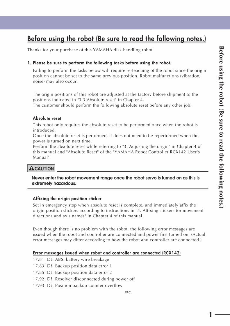
Before using the robot (Be sure to read the following notes.) Thanks for your purchase of this YAMAHA disk handling robot.
1. Please be sure to perform the following tasks before using the robot.
Failing to perform the tasks below will require re-teaching of the robot since the origin position cannot be set to the same previous position. Robot malfunctions (vibration, noise) may also occur.
The origin positions of this robot are adjusted at the factory before shipment to the positions indicated in "3.3 Absolute reset" in Chapter 4.The customer should perform the following absolute reset before any other job.
Absolute resetThis robot only requires the absolute reset to be performed once when the robot is introduced.Once the absolute reset is performed, it does not need to be reperformed when the power is turned on next time. Perform the absolute reset while referring to "3. Adjusting the origin" in Chapter 4 of this manual and "Absolute Reset" of the "YAMAHA Robot Controller RCX142 User's Manual".
! CAUTION
Never enter the robot movement range once the robot servo is turned on as this is extremely hazardous.
Affixing the origin position stickerSet in emergency stop when absolute reset is complete, and immediately affix the origin position stickers according to instructions in "5. Affixing stickers for movement directions and axis names" in Chapter 4 of this manual.
Even though there is no problem with the robot, the following error messages are issued when the robot and controller are connected and power first turned on. (Actual error messages may differ according to how the robot and controller are connected.)
Error messages issued when robot and controller are connected (RCX142)17.81: D?. ABS. battery wire breakage
17.83: D?. Backup position data error 1
17.85: D?. Backup position data error 2
17.92: D?. Resolver disconnected during power off
17.93: D?. Position backup counter overflow
etc.

Before using the robot (B
e sure to read the following notes.)
2
2. If the X-axis or Y-axis rotation angle is small
If the X-axis or Y-axis rotation angle is smaller than 5° so that it always moves in the same position, an oil film is difficult to be formed on the joint support bearing, possibly leading to damage to the bearing. In this type of operation, add a movement so that the joint moves through 90° or more, about 5 times a day.
3. If the Z-axis or R-axis travel distance is short
If the Z-axis or R-axis travel distance is shorter than 5mm so that it always moves in the same position, an oil film is difficult to be formed on the linear motion bearing, possibly leading to damage to the bearing. In this type of operation, add a movement so that the axis moves more than 5mm, about 5 times a day.

Introduction
3
IntroductionThe disk handling robot arm is a two-joint manipulator comprising X and Y axes, with a tool attachment shaft at the manipulator tip. The robot also has a Z-axis that moves the arm up and down and an R-axis that serves as a travel axis. This configuration is ideal for handling DVD disks, etc. Please note that this robot is not completely designed for clean room use because the travel axis does not conform to clean room specifications.
This user's manual describes the safety measures, handling, adjustment, inspection and maintenance of the disk handling robots for correct, safe and effective use. Be sure to read this manual carefully before installing the robot. Even after reading this manual, keep it in a safe and convenient place for future reference. This user's manual should be used with the robot and considered an integral part of it. When the robot is moved, transferred or sold, be sure to send this manual to the new user along with the robot, and explain to the new user the need to read through this manual. For robot operation and programming details, refer to the "YAMAHA Robot Controller RCX142 Series User's Manual".
NOTES
• The contents of this manual are subject to change without prior notice.• Information furnished by YAMAHA in this manual is believed to be reliable.
However, if you find any part unclear or inaccurate in this manual, please contact YAMAHA sales office or dealer.
YAMAHA MOTOR CO., LTD.IM Operations

MEMO
4

i
General C
ontents
General Contents
Chapter 1 Using the Robot Safely
1. Safety information 1-1
2. Essential caution items 1-2
3. Special training for industrial robot operation 1-8
4. Robot safety functions 1-9
5. Safety measures for the system 1-10
6. Trial operation 1-10
7. Work within the safety enclosure 1-11
8. Automatic operation 1-12
9. Adjustment and inspection 1-12
10. Repair and modification 1-12
11. Warranty 1-13
12. CE Marking 1-14
Chapter 2 Functions
1. Robot manipulator 2-1
2. Robot controller 2-4
3. Parameter factory settings 2-5
Custom parameter sheet 2-5
Chapter 3 Installation
1. Robot installation conditions 3-1
1.1 Installation environments 3-1
1.2 Installation base 3-2
2. Installation 3-4
2.1 Unpacking 3-4
2.2 Checking the product 3-5
2.3 Moving the robot 3-6
2.3.1 4-axis model 3-6
2.3.2 3-axis model 3-8
2.4 Installing the robot 3-10
2.4.1 4-axis model 3-10
2.4.2 3-axis model 3-11
2.5 Adjusting the robot base tilt 3-12
3. Protective bonding 3-13

ii
General C
ontents
4. Robot cable connection 3-15
5. User wiring connector and user tubing 3-16
5.1 User wiring 3-17
5.2 User tubing 3-20
6. Attaching the end effector 3-21
6.1 Acceleration 3-21
6.2 Equation for moment of inertia calculation 3-22
6.3 Example of moment of inertia calculation 3-25
6.4 End effector attachment strength and rigidity 3-27
6.5 Attaching the end effector 3-29
6.6 Adjusting the end effector tilt (when equipped with hand holder) 3-33
6.7 Gripping force of end effector 3-34
7. Working envelope and mechanical stopper positions for maximum working envelope 3-35
8. Base suction tube 3-36
Chapter 4 Adjustment
1. Overview 4-1
2. Safety precautions 4-1
3. Adjusting the origin 4-2
3.1 Absolute reset method 4-3
3.1.1 Sensor method (X-axis and Y-axis) 4-3
3.1.2 Stroke end method (Z-axis and R-axis) 4-3
3.2 Machine reference 4-4
3.3 Absolute reset procedures 4-5
3.3.1 Sensor method (X-axis and Y-axis) 4-5
3.3.2 Strike end method (Z-axis and R-axis) 4-8
3.4 Removing the robot covers 4-9
3.5 Adjusting the machine reference 4-10
3.5.1 Adjusting the X-axis machine reference 4-10
3.5.2 Adjusting the Y-axis machine reference 4-12
3.5.3 Adjusting the Z-axis machine reference 4-14
4. Setting the soft limits 4-16
5. Affixing stickers for movement directions and axis names 4-17
6. Adjusting the timing belt tension 4-19
6.1 Adjusting the X-axis, Y-axis, and Z-axis motor belt tension 4-19
6.2 Adjusting the timing belt tension for the X-axis and Y-axis arms 4-24
6.2.1 Adjusting the X-axis arm belt 4-24
6.2.2 Adjusting the Y-axis arm belt 4-25
7. X-axis and Y-axis arm alignment 4-27

iii
General C
ontents
Chapter 5 Operating the Robot
1. Robot motion 5-1
2. Operating the robot 5-2
3. Creating point data, direct teaching, and external forces to arms 5-5
Chapter 6 Periodic Inspection
1. Overview 6-1
2. Precautions 6-2
3. Daily inspection 6-3
4. Six-month inspection 6-5
5. Replacing the harmonic drive grease 6-7
5.1 Replacement interval 6-7
Chapter 7 Specifications
1. Basic specifications 7-1
2. External view and dimensions 7-3
3. Robot's internal wiring diagram 7-15
4. Robot's internal tubing 7-16
5. Wiring tables 7-17
6. Maintenance parts 7-28

iv
MEMO

Chapter 1 Using the Robot Safely
Contents
1. Safety information 1-1
2. Essential caution items 1-2
3. Special training for industrial robot operation 1-8
4. Robot safety functions 1-9
5. Safety measures for the system 1-10
6. Trial operation 1-10
7. Work within the safety enclosure 1-11
8. Automatic operation 1-12
9. Adjustment and inspection 1-12
10. Repair and modification 1-12
11. Warranty 1-13
12. CE Marking 1-14


Using the R
obot Safely
1
1-1
1. Safety information
1. Safety information Industrial robots are highly programmable, mechanical devices that provide a large degree of freedom when performing various manipulative tasks. To ensure correct and safe use of YAMAHA industrial robots, carefully read this manual and make yourself well acquainted with the contents. FOLLOW THE WARNINGS, CAUTIONS AND INSTRUCTIONS INCLUDED IN THIS MANUAL. Failure to take necessary safety measures or mishandling due to not following the instructions in this manual may result in trouble or damage to the robot and injury to personnel (robot operator or service personnel) including fatal accidents.
Warning information in this manual is classified by the following signal words.
DANGER
"DANGER" indicates an imminently hazardous situation which, if not avoided, will result in death or serious injury.
WARNING
"WARNING" indicates a potentially hazardous situation which, if not avoided, could result in death or serious injury.
! CAUTION
"CAUTION" indicates a potentially hazardous situation which, if not avoided, could result in minor or moderate injury or damage to the equipment or software.
Refer to the user's manual by any of the following methods to operate or adjust the robot safely and correctly.
1. Operate or adjust the robot while referring to the printed version of the user's manual (available for an additional fee).
2. Operate or adjust the robot while viewing the CD-ROM version of the user's manual on your computer screen.
3. Operate or adjust the robot while referring to a printout of the necessary pages from the CD-ROM version of the user's manual.
It is not possible to detail all safety items within the limited space of this manual. So it is essential that the user have a full knowledge of basic safety rules and also that the operator makes correct judgments on safety procedures during operation. This manual and warning labels supplied with or affixed to the robot are written in English. If the robot operator or service personnel do not understand English, do not permit him/her to handle the robot.
Using the R
obot Safely
1
1-2
2. Essential caution items
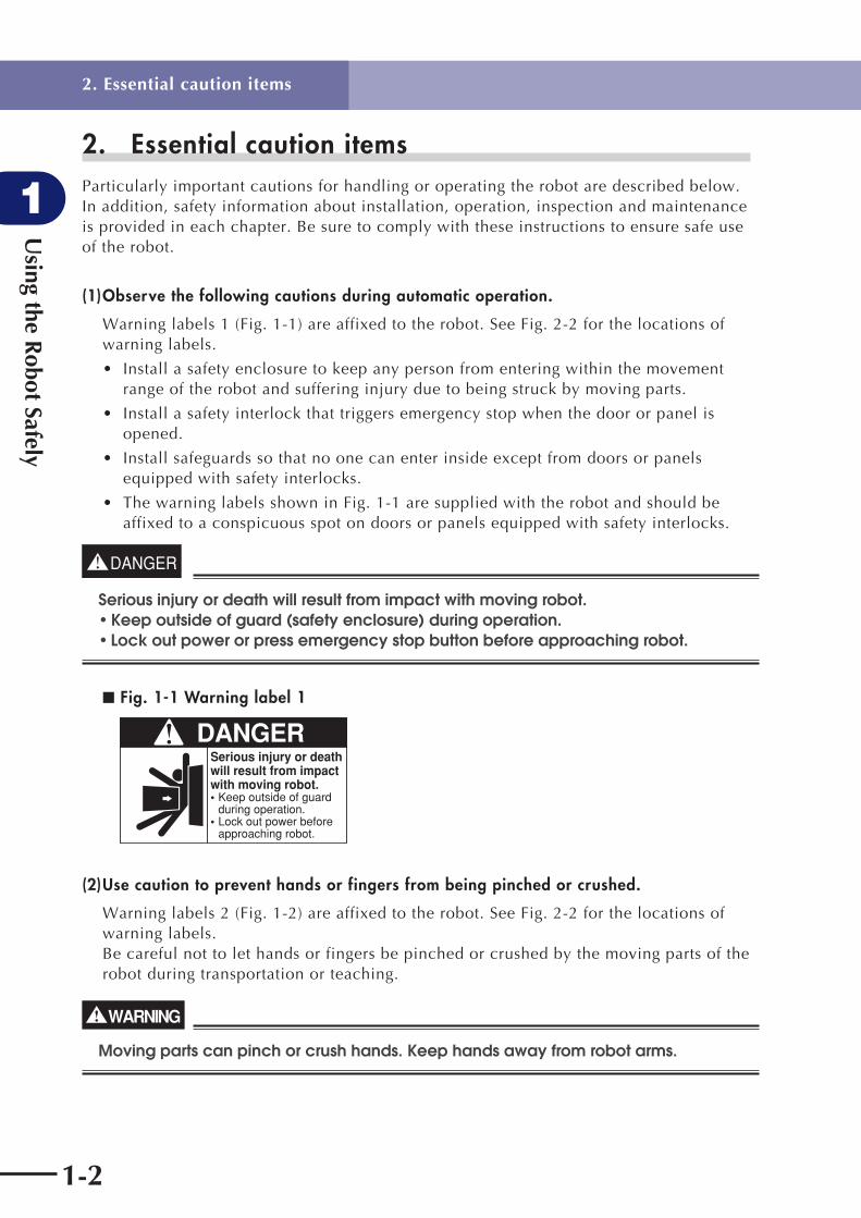
2. Essential caution items Particularly important cautions for handling or operating the robot are described below. In addition, safety information about installation, operation, inspection and maintenance is provided in each chapter. Be sure to comply with these instructions to ensure safe use of the robot.
(1) Observe the following cautions during automatic operation.
Warning labels 1 (Fig. 1-1) are affixed to the robot. See Fig. 2-2 for the locations of warning labels.
• Install a safety enclosure to keep any person from entering within the movement range of the robot and suffering injury due to being struck by moving parts.
• Install a safety interlock that triggers emergency stop when the door or panel is opened.
• Install safeguards so that no one can enter inside except from doors or panels equipped with safety interlocks.
• The warning labels shown in Fig. 1-1 are supplied with the robot and should be affixed to a conspicuous spot on doors or panels equipped with safety interlocks.
DANGER
Serious injury or death will result from impact with moving robot. • Keep outside of guard (safety enclosure) during operation. • Lock out power or press emergency stop button before approaching robot.
■ Fig. 1-1 Warning label 1
DANGERSerious injury or death will result from impactwith moving robot.• Keep outside of guard
during operation.• Lock out power before
approaching robot.
(2) Use caution to prevent hands or fingers from being pinched or crushed.
Warning labels 2 (Fig. 1-2) are affixed to the robot. See Fig. 2-2 for the locations of warning labels. Be careful not to let hands or fingers be pinched or crushed by the moving parts of the robot during transportation or teaching.
WARNING
Moving parts can pinch or crush hands. Keep hands away from robot arms.

Using the R
obot Safely
1
1-3
2. Essential caution items
■ Fig. 1-2 Warning label 2
Moving parts can pinch or crush.Keep hands away from robot arms.
WARNING
(3) Follow the instructions on warning labels and in this manual.
Warning label 3 (Fig. 1-3) is affixed to the robot. See Fig. 2-2 for the locations of warning labels.
• Be sure to read the warning labels and this manual carefully and make sure you thoroughly understand their contents before attempting installation and operation of the robot.
• Before starting robot operation, even after you have read through this manual, read again the procedures and cautions relating to your work as well as the description in this chapter (Chapter 1, "Using the Robot Safely").
• Never install, adjust, inspect or service the robot in any manner that does not comply with the instructions in this manual.
WARNING
Improper installation or operation can result in serious injury or death. Read user's manual and all warning labels before installation and operation.
■ Fig. 1-3 Warning label 3
Improper Installation or operation can result in serious injury or death. Read user's (owner's) manual and all warning labels before operation.
WARNING
(4) Do not use the robot in environments containing inflammable gas, etc.
WARNING
• This robot was not designed for operation in environments where infl ammable or explosive substances are present. • Do not use the robot in environments containing infl ammable gas, dust or liquids. Explosions or fi re may otherwise result.
Using the R
obot Safely
1
1-4
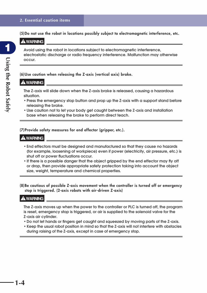
(5) Do not use the robot in locations possibly subject to electromagnetic interference, etc.
WARNING
Avoid using the robot in locations subject to electromagnetic interference, electrostatic discharge or radio frequency interference. Malfunction may otherwise occur.
(6) Use caution when releasing the Z-axis (vertical axis) brake.
WARNING
The Z-axis will slide down when the Z-axis brake is released, causing a hazardous situation. • Press the emergency stop button and prop up the Z-axis with a support stand before releasing the brake. • Use caution not to let your body get caught between the Z-axis and installation base when releasing the brake to perform direct teach.
(7) Provide safety measures for end effector (gripper, etc.).
WARNING
• End effectors must be designed and manufactured so that they cause no hazards (for example, loosening of workpiece) even if power (electricity, air pressure, etc.) is shut off or power fl uctuations occur. • If there is a possible danger that the object gripped by the end effector may fl y off or drop, then provide appropriate safety protection taking into account the object size, weight, temperature and chemical properties.
(8) Be cautious of possible Z-axis movement when the controller is turned off or emergency stop is triggered. (2-axis robots with air-driven Z-axis)
WARNING
The Z-axis moves up when the power to the controller or PLC is turned off, the program is reset, emergency stop is triggered, or air is supplied to the solenoid valve for the Z-axis air cylinder. • Do not let hands or fi ngers get caught and squeezed by moving parts of the Z-axis. • Keep the usual robot position in mind so that the Z-axis will not interfere with obstacles during raising of the Z-axis, except in case of emergency stop.
2. Essential caution items

Using the R
obot Safely
1
1-5
(9) Use caution when the Z-axis is interfering with peripheral equipment. (2-axis robots with air driven Z-axis)
WARNING
When the Z-axis comes to a stop due to obstructions from peripheral equipment, the Z-axis may move suddenly when the obstruction is removed, causing injury such as pinched or crushed hands. • Turn off the controller and reduce the air pressure before attempting to remove the obstruction. • Before reducing the air pressure, place a support stand under the Z-axis because it will drop under its own weight.
(10) Use caution on Z-axis movement when air supply is stopped. (2-axis robots with air-driven Z-axis)
WARNING
The Z-axis may suddenly drop when the air pressure to the Z-axis air cylinder solenoid valve is reduced, creating a hazardous situation. Turn off the controller and place a prop or support under the Z-axis before cutting off the air supply.
(11) Use caution when disassembling or replacing the pneumatic equipment.
WARNING
Air or parts may fl y outwards if pneumatic equipment is disassembled or parts replaced while air is still supplied.• Do service work after fi rst turning off the controller and reducing the air pressure.• Before reducing the air pressure, place a support stand under the Z-axis (2-axis robots with air-driven Z-axis) because it will drop under its own weight.
(12) Use caution when removing the Z-axis motor.
WARNING
The Z-axis will drop when the Z-axis motor is removed, causing a hazardous situation. • Turn off the controller and set a support stand under the Z-axis before removing the motor. • Use caution not to allow hands or body to be squeezed or crushed by moving parts on the Z-axis or between the Z-axis and the installation base.
2. Essential caution items

Using the R
obot Safely
1
1-6
(13) Use caution during inspection of controller.
WARNING
• When you need to touch the terminals or connectors on the outside of the controller during inspection, always fi rst turn off the controller power switch and also the power source in order to prevent possible electrical shock.• Never touch any internal parts of the controller.
For precautions on handling the controller, refer to the "YAMAHA Robot Controller User's Manual".
(14) Consult us for corrective action when the robot is damaged or malfunction occurs.
WARNING
If any part of the robot is damaged or any malfunction occurs, continuous operation may be very dangerous. Please consult YAMAHA sales offi ce or dealer for corrective action.
Damage or Trouble Possible Danger
Damage to machine harness or robot cable Electrical shock, malfunction of robot
Damage to exterior of robotFlying outwards of damaged parts during robot operation
Abnormal operation of robot(positioning error, excessive vibration, etc.)
Malfunction of robot
Z-axis brake trouble Dropping of load
(15) Use caution not to touch the high temperature motor or speed reduction gear casing.
WARNING
The motor and speed reduction gear casing are extremely hot after automatic operation, so burns may occur if these are touched. Before touching these parts during inspections or servicing, turn off the controller, wait for a while and check that the temperature has cooled.
(16) Do not remove, alter or stain the warning labels.
WARNING
If warning labels are removed or diffi cult to see, necessary cautions may not be taken, resulting in an accident.• Do not remove, alter or stain the warning labels on the robot. • Do not allow the warning labels to be hidden by the device installed to the robot by the user. • Provide proper lighting so that the symbols and instructions on the warning labels can be clearly seen even from the outside of safety enclosure.
2. Essential caution items

Using the R
obot Safely
1
1-7
(17) Protective bonding
WARNING
Be sure to ground the robot and controller to prevent electrical shock.
(18) Be sure to make correct parameter settings.
! CAUTION
The robot must be operated with an acceleration rate that is appropriate for the manipulator tip's weight and moment of inertia. If this is not observed, premature end to the life of the drive units, damage to the robot parts or residual vibration during positioning may result.
(19) Do not use the robot for tasks requiring motor thrust.
! CAUTION
Avoid using the disk handling robot for tasks which make use of motor thrust (press-fi tting, burr removal, etc.). These tasks may cause malfunctions of the robot.
(20) If the X-axis or Y-axis rotation angle is small
! CAUTION
If the X-axis or Y-axis rotation angle is smaller than 5° so that it always moves in the same position, an oil fi lm is diffi cult to be formed on the joint support bearing, possibly leading to damage to the bearing. In this type of operation, add a movement so that the joint moves through 90° or more, about 5 times a day.
(21) If the Z-axis or R-axis travel distance is short
! CAUTION
If the Z-axis or R-axis travel distance is shorter than 5mm so that it always moves in the same position, an oil fi lm is diffi cult to be formed on the linear motion bearing, possibly leading to damage to the bearing. In this type of operation, add a movement so that the axis moves more than 5mm, about 5 times a day.
2. Essential caution items

Using the R
obot Safely
1
1-8
3. Special training for industrial robot operationCompanies or factories using industrial robots must make sure that every person, who handles the robot such as for teaching, programming, movement check, inspection, adjustment and repair, has received appropriate training and also has the skills needed to perform the job correctly and safely. Since the YAMAHA disk handling robots fall under the industrial robot category, the user must observe local regulations and safety standards for industrial robots, and provide special training for every person involved in robot-related tasks (teaching, programming, movement check, inspection, adjustment, repair, etc.).
3. Special training for industrial robot operation

Using the R
obot Safely
1
1-9
4. Robot safety functions
(1) Overload detection
This function detects an overload applied to the motor and shuts off the servo power. If an overload error occurs, take the following measures.
1. Insert a timer in the program.
2. Reduce the acceleration coefficient.
(2) Overheat detection
This function detects an abnormal temperature rise in the driver inside the controller and shuts off the servo power. If an overheat error occurs, take the following measures.
1. Insert a timer in the program.
2. Reduce the acceleration coefficient.
(3) Soft limits
Soft limits can be set on each axis to limit the working envelope in manual operation after return-to-origin and during automatic operation. The working envelope is the area limited by soft limits.
(4) Mechanical stoppers
If the servo power is suddenly shut off during high-speed operation by emergency stop or safety functions, these mechanical stoppers prevent the axis from exceeding the movement range. The movement range is the area limited by mechanical stoppers.
• The X, Y, Z and R axes have fixed mechanical stoppers at their movement range limits in plus and minus directions.
WARNING
Axis movement will not stop immediately after the servo power supply is shut off by emergency stop or other safety functions, so use caution.
(5) Z-axis (vertical axis) brake
An electromagnetic brake is installed on the Z-axis to prevent the Z-axis from sliding down when servo power is turned off. This brake is working when the controller power is off or the Z-axis servo power is off even when the controller power is on. The Z-axis brake can be released by means of the programming unit or by a command in the program when the controller power is on.
WARNING
The Z-axis will slide down when the Z-axis brake is released, creating a hazardous situation. • Press the emergency stop button and prop the Z-axis with a support stand before releasing the brake. • Use caution not to let your body get caught between the Z-axis and installation base when releasing the brake to perform direct teach.
4. Robot safety functions

Using the R
obot Safely
1
1-10
5. Safety measures for the system Since the robot is commonly used in conjunction with an automated system, dangerous situations are more likely to occur from the automated system than from the robot itself. Accordingly, appropriate safety measures must be taken on the part of the system manufacturer according to the individual system. The system manufacturer should provide a proper instruction manual for safe, correct operation and servicing of the system.
6. Trial operationAfter making installations, adjustments, inspections, maintenance or repairs to the robot, make a trial run using the following procedures.
(1) If a safety enclosure has not yet been provided right after installation of the robot, rope off or chain off around the movement area of the manipulator in place of the safety enclosure, and observe the following points.
1. Use sturdy, stable posts which will not fall over easily.
2. The rope or chain should be easily visible by everyone around the robot.
3. Place a sign to keep the operator or other personnel from entering the movement range of the manipulator.
(2) Check the following points before turning on the controller.
1. Is the robot securely and correctly installed?
2. Are the electrical connections to the robot correct?
3. Are items such as air pressure correctly supplied?
4. Is the robot correctly connected to peripheral equipment?
5. Have safety measures (safety enclosure, etc.) been taken?
6. Does the installation environment meet the specified standards?
(3) After the controller is turned on, check the following points from outside the safety enclosure.
1. Does the robot start and stop as intended? Can the operation mode be selected correctly?
2. Does each axis move as intended within the soft limits?
3. Does the end effector move as intended?
4. Are the signal transmissions to the end effector and peripheral equipment correct?
5. Does emergency stop work?
6. Are the teaching and playback functions normal?
7. Are the safety enclosure and interlock working as intended?
8. Does the robot move correctly during automatic operation?
5. Safety measures for the system

Using the R
obot Safely
1
1-11
7. Work within the safety enclosure
(1) When work is required inside the safety enclosure, always turn off the controller and place a sign indicating that the robot is being adjusted or serviced in order to keep any other person from touching the controller switch or operation panel, except for the following cases.
1) Origin position setting (See section 3 in Chapter 4.)
2) Soft limit setting (See section 4 in Chapter 4.)
3) X-axis and Y-axis arm alignment (See section 7 in Chapter 4.)
4) Teaching
For items 1), 2) and 3), follow the precautions and procedure described in each section. To perform item 4), refer to the description in (2) below.
(2) Teaching
When performing teaching within the safety enclosure, comply with the instructions listed below.
1) Check or perform the following points from outside the safety enclosure.
1. Make sure that no hazards are present within the safety enclosure by a visual check.
2. Check that the programming unit MPB operates correctly.
3. Check that no failures are found in the robot.
4. Check that emergency stop works correctly.
5. Select teaching mode and prohibit automatic operation.
2) Never enter the movement range of the robot while within the safety enclosure.
7. Work within the safety enclosure

Using the R
obot Safely
1
1-12
8. Automatic operation Automatic operation described here includes all operations in AUTO mode.
(1) Check the following before starting automatic operation.
1. No one is within the safety enclosure.
2. The programming unit and tools are in their specified locations.
3. The alarm or error lamps on the robot and peripheral equipment do not flash.
4. The safety enclosure is securely installed with safety interlocks actuated.
(2) Observe the following during automatic operation or in cases where an error occurs.
1) After automatic operation has started, check the operation status and warning lamp to ensure that the robot is in automatic operation.
2) Never enter the safety enclosure during automatic operation.
3) If an error occurs in the robot or peripheral equipment, observe the following procedure before entering the safety enclosure.
1. Press the emergency stop button to set the robot to emergency stop.
2. Place a sign on the start switch, indicating that the robot is being inspected in order to keep any other person from touching the start switch and restarting the robot.
9. Adjustment and inspection Do not attempt any installation, adjustment, inspection or maintenance unless it is described in this manual.
10. Repair and modification Do not attempt any repair, parts replacement and modification unless described in this manual. These works require technical knowledge and skill, and may also involve work hazards.
8. Automatic operation

Using the R
obot Safely
1
1-13
11. Warranty The YAMAHA robot and/or related product you have purchased are warranted against the defects or malfunctions as described below.
Warranty description:
If a failure or breakdown occurs due to defects in materials or workmanship in the genuine parts constituting this YAMAHA robot and/or related product within the warranty period, then YAMAHA will repair or replace those parts free of charge (hereafter called "warranty repair").
Warranty Period:
The warranty period ends when any of the following applies:
1) After 18 months (one and a half year) have elapsed from the date of shipment
2) After one year has elapsed from the date of installation
3) After 2,400 hours of operation
Exceptions to the Warranty:
This warranty will not apply in the following cases:
1) Fatigue arising due to the passage of time, natural wear and tear occurring during operation (natural fading of painted or plated surfaces, deterioration of parts subject to wear, etc.)
2) Minor natural phenomena that do not affect the capabilities of the robot and/or related product (noise from computers, motors, etc.).
3) Programs, point data and other internal data that were changed or created by the user.
Failures resulting from the following causes are not covered by warranty repair.
1) Damage due to earthquakes, storms, floods, thunderbolt, fire or any other natural or man-made disasters.
2) Troubles caused by procedures prohibited in this manual.
3) Modifications to the robot and/or related product not approved by YAMAHA or YAMAHA sales representatives.
4) Use of any other than genuine parts and specified grease and lubricants.
5) Incorrect or inadequate maintenance and inspection.
6) Repairs by other than authorized dealers.
YAMAHA MOTOR CO., LTD. MAKES NO OTHER EXPRESS OR IMPLIED WARRANTIES, INCLUDING ANY IMPLIED WARRANTY OF MERCHANTABILITY OR FITNESS FOR ANY PARTICULAR PURPOSE. THE WARRANTY SET FORTH ABOVE IS EXCLUSIVE AND IS IN LIEU OF ALL EXPRESSED OR IMPLIED WARRANTIES, INCLUDING WARRANTIES OF MERCHANTABILITY, FITNESS FOR A PARTICULAR PURPOSE, OR WARRANTIES ARISING FROM A COURSE OF DEALING OR USAGE OF TRADE. YAMAHA MOTOR CO., LTD. SOLE LIABILITY SHALL BE FOR THE DELIVERY OF THE EQUIPMENT AND YAMAHA MOTOR CO., LTD. SHALL NOT BE LIABLE FOR ANY CONSEQUENTIAL DAMAGES (WHETHER ARISING FROM CONTRACT, WARRANTY, NEGLIGENCE OR STRICT LIABILITY). YAMAHA MOTOR CO., LTD. MAKES NO WARRANTY WHATSOEVER WITH REGARD TO ACCESSORIES OR PARTS NOT SUPPLIED BY YAMAHA MOTOR CO., LTD.
11. Warranty

Using the R
obot Safely
1
1-14
12. CE MarkingWhen the YAMAHA robots are exported to or used in EU (European Union) countries, refer to the separate "YAMAHA Robot Controller User's Manual" or "CE Marking Supporting Supplement Manual" for related information about CE marking.
12. CE Marking

Chapter 2 Functions
Contents
1. Robot manipulator 2-1
2. Robot controller 2-4
3. Parameter factory settings 2-5
Custom parameter sheet 2-5

Functions
2
2-1
1. Robot manipulator
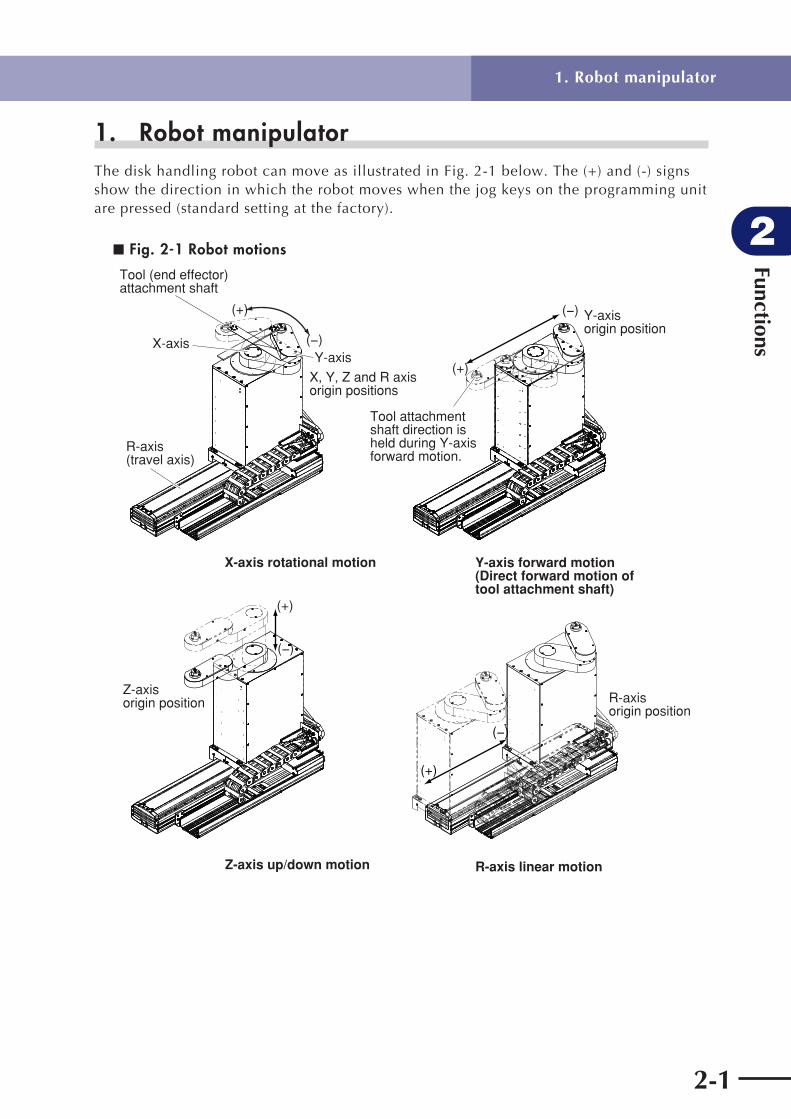
1. Robot manipulatorThe disk handling robot can move as illustrated in Fig. 2-1 below. The (+) and (-) signs show the direction in which the robot moves when the jog keys on the programming unit are pressed (standard setting at the factory).
■ Fig. 2-1 Robot motions
X-axis
Tool (end effector)attachment shaft
R-axis (travel axis)
Y-axis
X, Y, Z and R axis origin positions
(+)
(−)
X-axis rotational motion
(+)
(−) Y-axis origin position
Tool attachment shaft direction is held during Y-axis forward motion.
(−)
(+)
Z-axis origin position
Z-axis up/down motion
(+)
(−)
R-axis origin position
R-axis linear motion
Y-axis forward motion(Direct forward motion of tool attachment shaft)

Functions
2
2-2
1. Robot manipulator
Fig. 2-2 to Fig. 2-5 below show part names and functions of each robot model.
■ Fig. 2-2 4-axis model (without hand holder)
X-axis armTool (end effector)attachment shaft
Y-axis arm
Y-axis motor and speed reduction gear
X-axis motor and speed reduction gear
Robot cable
Cable carrier
Warning label 1Warning label 2Warning label 3
Z-axis ball screw, guide and motor
Base tilt adjustment screw
Travel axis (R-axis)
Warning label 2
User tubing 2User tubing 1
User wiring
Wiring boxUser wiring connector(pins 1 to 4 usable)
User tubing 2 ( 4)
User tubing 1 ( 4)
Suction coupler ( 12 × 2)
ground terminal
Serial number label

Functions
2
2-3
1. Robot manipulator
■ Fig. 2-3 4-axis model (with hand holder)
Hand holder(User tubing 2 and user wiring inside)
End effector attachment
User tubing 1 at lower part
■ Fig. 2-4 3-axis model (without hand holder)
Suction coupler ( 12 2)
User wiring connector (pins 1 to 4 usable)
Robot cable
Ground terminalBase tilt adjustment screwUser tubing 2 ( 4)
User tubing 1 ( 4)
■ Fig. 2-5 3-axis model (with hand holder)
Hand holder

Functions
2
2-4
2. Robot controllerAn RCX142 controller is used with the disk handling robot. For detailed information on the controller, refer to the separate "YAMAHA Robot Controller RCX142 Series User's Manual".
■ Fig. 2-6 RCX142
RCX142MOTOR
XM
YM
ZM
RM
PWR
SRV
ERR
SAFETY
MPB
COM
STD.DIO
RGEN
ACIN
P
N
L
N
ROBI/O
XY
ROBI/O
ZR
OP.1 OP.3
OP.2 OP.4
200-230V~50-60Hz
MAX.2500VA
BATT
ZR
XY
MODEL.SER. NO.MANUFACTUREDFACTORY AUTOMATION EQUIPMENT MADE IN JAPAN
CAUTION
READ INSTRUCTIONMANUAL
2. Robot controller

Functions
2
2-5
3. Parameter factory settingsThis robot is a custom-order item, and therefore has customized parameters. Be sure to make a backup copy of the parameter factory settings. The parameter settings will be lost if the parameters are initialized. In that event, use the backup data to download the parameter settings again. The parameters are indicated on the custom parameter sheet attached to each robot.
Custom parameter sheet
To purchasers of this custom-made robotThank you for purchase of this YAMAHA robot.This robot is a custom-order item, and therefore shipped with parameters customized by changing the standard robot settings. If this robot is used with parameter settings that differ from the "customized parameter settings", this may cause problems such as malfunctions. Do not change the customized parameter settings indicated on the custom parameter sheet.The parameter settings will be lost if the robot parameters are initialized. In that event, set the parameters again.Make a backup of the parameter settings before using the robot.Please keep the custom parameter sheet carefully along with the user's manual, as it will be needed in cases where the parameters have to be set again.
Setting models
Model Serial No.Date of manufacture
(month/year)
Mechanical unit Disk handling 3-axis robot + F17
Controller RCX142
Customized parameter settingsCustomized parameter settings are shown below. Boxes left blank indicate standard parameter settings.
Robot configurationConfiguration Robot name Robot No.
Main robot MULTI 170
Axis configurationConfiguration Axis name Axis No. Custom setting
M1 F14H-20 4060
M2 F14-20 4050
M3 F17-20V 4072
M4 F17-10 4071
Robot settingsName Changed value
Name Changed value
Tip mass 0
Return-to-origin sequence 231456
* On the 3-axis model (X, Y and Z axes) using an RCX142 controller, only M1 to M3 settings are needed.
3. Parameter factory settings

Functions
2
2-6
Axis settings (Blank boxes indicate default settings. Do not change them.)
NameChanged value
M1 M2 M3 M4
+ soft limit 386844 269654 163840
- soft limit -386844 -4552
Return-to-origin method Sensor Sensor
Axis polarity + + +
Acceleration 1300 1200 3000
←Never increase acceleration more than this level.
Kvp 6000 3900 1500
Kvi 4000 2600 1000
Motor model 285 246 257
Overload reference 2949
Overload time 2548
Id max 380
Id limit 22
Maximum torque command
1255
Maximum motor revolution
5000 5000 2000
←Never change maximum motor revolution.
Kip 48
Kii 32
Origin position return pulse
0
Stroke-end origin position torque
80
* On the 3-axis model (X, Y and Z axes) using an RCX142 controller, only M1 to M3 settings are needed.
3. Parameter factory settings

Chapter 3 Installation
Contents
1. Robot installation conditions 3-1
1.1 Installation environments 3-1
1.2 Installation base 3-2
2. Installation 3-4
2.1 Unpacking 3-4
2.2 Checking the product 3-5
2.3 Moving the robot 3-6
2.3.1 4-axis model 3-6
2.3.2 3-axis model 3-8
2.4 Installing the robot 3-10
2.4.1 4-axis model 3-10
2.4.2 3-axis model 3-11
2.5 Adjusting the robot base tilt 3-12
3. Protective bonding 3-13
4. Robot cable connection 3-15
5. User wiring connector and user tubing 3-16
5.1 User wiring 3-17
5.2 User tubing 3-20
6. Attaching the end effector 3-21
6.1 Acceleration 3-21
6.2 Equation for moment of inertia calculation 3-22
6.3 Example of moment of inertia calculation 3-25
6.4 End effector attachment strength and rigidity 3-27
6.5 Attaching the end effector 3-29
6.6 Adjusting the end effector tilt (when equipped with hand holder) 3-33
6.7 Gripping force of end effector 3-34
7. Working envelope and mechanical stopper positions for maximum working envelope 3-35
8. Base suction tube 3-36


Installation
3
3-1
1. Robot installation conditions
1. Robot installation conditions
1.1 Installation environmentsBe sure to install the robot in the following environments.
Items Specifications
Allowable ambient temperature 0 to 40°C
Allowable ambient humidity 35 to 85% RH (non condensation)
Altitude 0 to 1000 meters above sea level
Ambient environments
Avoid installing near water, cutting water, oil, dust, metallic chips and organic solvent.
Avoid installation near corrosive gas and corrosive materials.
Avoid installation in atmosphere containing inflammable gas, dust or liquid.
Avoid installation near objects causing electromagnetic interference, electrostatic discharge or radio frequency interference.
Vibration Do not subject to impacts or vibrations.
Air supply pressure, etc.
Below 0.58MPa (6.0kgf/cm2); clean dry air not containing deteriorated compressor oil; filtration 40µm or less
Working space Allow sufficient space margin to perform jobs (teaching, inspection, repair, etc.)
For detailed information on how to install the robot controller, refer to the separate "YAMAHA Robot Controller User's Manual".
WARNING
• Avoid installing the robot in locations where the ambient conditions may exceed the allowable temperature or humidity, or in environments where water, corrosive gases, metallic powder or dust are generated. Malfunction, failure or short circuits may otherwise result.• This robot was not designed for operation in environments where infl ammable or explosive substances are present. Do not use the robot in environments containing infl ammable gas, dust or liquids. Explosions or fi re could otherwise result.• Avoid using the robot in locations subject to electromagnetic interference, electrostatic discharge or radio frequency interference. Malfunction may otherwise occur.• Do not use the robot in locations subject to excessive vibration. Robot installation bolts may otherwise become loose causing the robot to fall over.

Installation
3
3-2
1. Robot installation conditions
1.2 Installation base
WARNING
Always install the robot on a level surface, with the robot base mount facing downward. Grease may leak out from the speed reduction gear if the robot is installed in such a way that the base mount does not face downward.
! CAUTION
• The manipulator positioning may decrease if the installation surface precision is insuffi cient.• If the installation base is not suffi ciently rigid and stable or a thin metallic plate is attached to the installation base, vibration (resonance) may occur during operation, causing detrimental effects on the manipulator work.
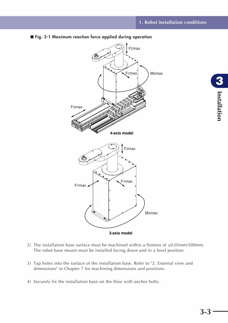
1) Prepare a sufficiently rigid and stable installation base, taking account of the robot weight including the end effector (gripper), workpiece and reaction force while the robot is operating.The maximum reaction force (see Fig.3-1) applied to the robot is as shown below. These values are an instantaneous force applied to the robot during operation and do not indicate the maximum load capacity.
Maximum reaction force during robot operation
Fxmax FYmax Mxmax Fzmax
N kgf N Kgf Nm kgfm N Kgf
1019 104 686 70 56 6 294 30
Installation
3
3-3
1. Robot installation conditions
■ Fig. 3-1 Maximum reaction force applied during operation
FZmax
FYmax MXmax
FXmax
4-axis model
FYmaxFYmax
FZmax
MXmax
3-axis model
2) The installation base surface must be machined within a flatness of ±0.05mm/500mm. The robot base mount must be installed facing down and in a level position.
3) Tap holes into the surface of the installation base. Refer to "2. External view and dimensions" in Chapter 7 for machining dimensions and positions.
4) Securely fix the installation base on the floor with anchor bolts.
Installation
3
3-4
2. Installation
2.1 Unpacking
WARNING
The robot and controller are heavy. Take suffi cient care not to drop them during moving or unpacking as this may damage the equipment or cause bodily injury.
! CAUTION
Allow only properly qualifi ed personnel to operate equipment such as forklifts that require a license to use. Equipment and tools used for moving the robot should be serviced daily.
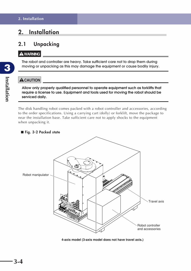
The disk handling robot comes packed with a robot controller and accessories, according to the order specifications. Using a carrying cart (dolly) or forklift, move the package to near the installation base. Take sufficient care not to apply shocks to the equipment when unpacking it.
■ Fig. 3-2 Packed state
Robot manipulator
Robot controllerand accessories
Travel axis
4-axis model (3-axis model does not have travel axis.)
2. Installation

Installation
3
3-5
2.2 Checking the productAfter unpacking, check the product configuration and conditions.
! CAUTION
If there is any damage due to transportation or insuffi cient parts, please notify your YAMAHA sales offi ce or dealer immediately.
■ Fig. 3-3 Product configuration
RCX142
MOTOR
XM
YM
ZM
RM
PWR
SRV
ERR
SAFETY
MPB
COM
STD.DIO
RGEN
ACIN
P
N
L
N
ROB
I/O
XY
ROB
I/O
ZR
OP.1OP.3
OP.2OP.4
200-230V~
50-60Hz
MAX.2500VA
MODEL.
SER. NO.
MANUFACTURED
FACTORY AUTOMATION EQUIPMENT MADE IN JAPAN
CAUTION
READ INSTRUCTION
MANUAL
BATT
ZR
XY
CD-ROM User’s Manualor User’s Manual
Robot cable
Warning label
4-axis model robot(3-axis model does not have travel axis.)
Movement direction andaxis name label
A BX YZ R
O-ring (for sealing of end effector attachment ) Model without hand holder : S7 2 pcs Model with hand holder : S5 1 pc
RCX142 controller
Options
MPB programming unit Expansion I/O connector
OP. DIO connector
User wiring connector
For 4-axis model
Pin
For 3-axis model
2. Installation

Installation
3
3-6
2.3 Moving the robot
WARNING
Serious injury may occur if the robot falls and pins someone underneath it.• Do not allow any part of your body within the area beneath the robot during work.• Always wear a helmet, safety shoes and gloves during work.
! CAUTION
• Allow only properly qualifi ed personnel to operate equipment such as cranes that require a license to use. • Equipment and tools used for moving the robot should be serviced daily.
2.3.1 4-axis modelThe robot weighs more than 70kg so take suitable precautions when carrying the robot.Use 3 or more people for the following work.
1) Move each axis to its origin position, and then turn off the controller and disconnect the robot cable from the controller. (The robot is bolted to a pallet at the time of shipment.)
■ Fig. 3-4
(a) (b)
(d) (c)
Installation base or pallet(This figure shows a pallet.)
New installation base
Push here by hand to move robot.
Push here by hand to move robot.
Lifter's fork
2) Wind the robot cable around the robot base and fasten the robot cable with adhesive tape. (See Fig. 3-4 (a).)
2. Installation

Installation
3
3-7
3) In the following work, hold the robot being careful to keep it balanced so it will not fall over.Remove the R-axis (travel axis) mounting bolts. (See "2.4 Installing the robot".)
4) Move the robot to one edge of the installation base (or pallet), by pushing the robot toward the edge with two people, one each at the ends of the R-axis (travel axis).
5) Have another person use a lifter to position it against the edge of the installation base (or pallet). Use a lifter with a maximum payload capacity sufficient to support the robot mass.
6) Shift the robot onto the forks of the lifter with two people. (See Fig. 3-4 (b).) Hold the robot while the lifter is moving up or down to ensure the robot will not fall over.
7) Move the robot on the lifter to the new installation base and then position the lifter against the edge of the installation base. At this point, hold the robot to ensure it will not fall over. (See Fig. 3-4 (c).)
8) Shift the robot onto the installation base with two people. Make sure the robot is stably placed on the installation base. (See Fig. 3-4 (d).)
9) Bolt the robot promptly by referring to the description in "2.4 Installing the robot".
2. Installation
Installation
3
3-8
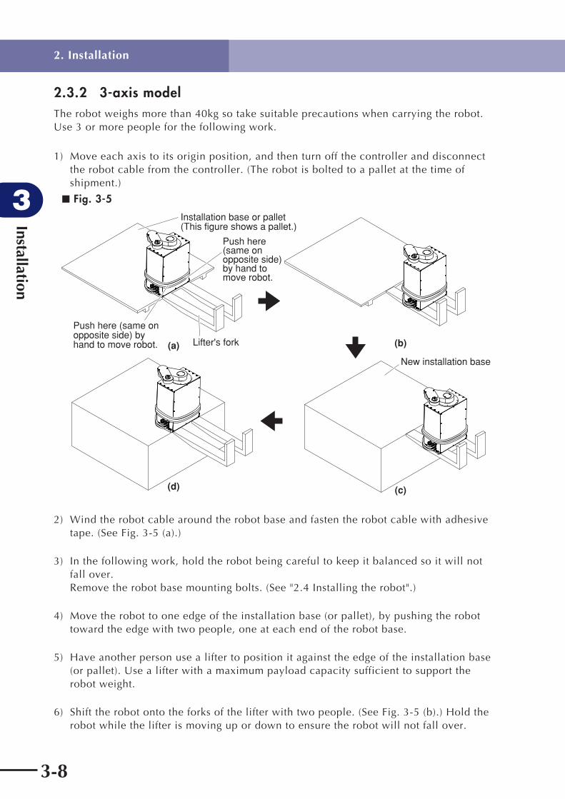
2.3.2 3-axis modelThe robot weighs more than 40kg so take suitable precautions when carrying the robot.Use 3 or more people for the following work.
1) Move each axis to its origin position, and then turn off the controller and disconnect the robot cable from the controller. (The robot is bolted to a pallet at the time of shipment.)
■ Fig. 3-5
(a) (b)
(d) (c)
Installation base or pallet(This figure shows a pallet.)
New installation base
Lifter's fork
Push here (same on opposite side) by hand to move robot.
Push here (same on opposite side) by hand to move robot.
2) Wind the robot cable around the robot base and fasten the robot cable with adhesive tape. (See Fig. 3-5 (a).)
3) In the following work, hold the robot being careful to keep it balanced so it will not fall over.Remove the robot base mounting bolts. (See "2.4 Installing the robot".)
4) Move the robot to one edge of the installation base (or pallet), by pushing the robot toward the edge with two people, one at each end of the robot base.
5) Have another person use a lifter to position it against the edge of the installation base (or pallet). Use a lifter with a maximum payload capacity sufficient to support the robot weight.
6) Shift the robot onto the forks of the lifter with two people. (See Fig. 3-5 (b).) Hold the robot while the lifter is moving up or down to ensure the robot will not fall over.
2. Installation

Installation
3
3-9
7) Move the robot on the lifter to the new installation base and then position the lifter against the edge of the installation base. At this point, hold the robot to ensure it will not fall over. (See Fig. 3-5 (c).)
8) Shift the robot onto the installation base with two people. Make sure the robot is stably placed on the installation base. (See Fig. 3-5 (d).)
9) Bolt the robot promptly by referring to the description in "2.4 Installing the robot".
2. Installation

Installation
3
3-10
2.4 Installing the robot
WARNING
• When installing the robot, use the specifi ed size and number of bolts that match the depth of tapped holes in the installation base, and securely tighten the bolts to the correct torque. If this is not observed, the robot might fall over during operation causing a serious accident.• Make sure that the bolts do not reach the bottom of the tapped holes.
2.4.1 4-axis modelThe method for installing the robot is described below.
1) Tap holes into the surface of the installation base where the robot is to be installed. Refer to "2. External view and dimensions" in Chapter 7 for machining positions.
2) Remove the screws holding the upper cover of the robot and remove the upper cover. Move the slider to a position where the mounting holes in the bottom of the robot are seen.
3) Fix the robot to the installation base with the specified bolts.
Bolt size Tightening torque Number of bolts
M8 37Nm (380Kgfcm) 10
Depth of tapped holes in installation base:Iron installation base 15mm or more (bolt length 40mm or more)Aluminum installation base 25mm or more (bolt length 50mm or more)
Recommended bolt : JIS B 1176 hex socket head bolt, or equivalent Strength class JIS B 1051 12.9, or equivalent
■ Fig. 3-6 Installing the robot
10 M8 bolts for robot installation(Screw into holes just outside guide.) Remove upper cover mounting
screws (2 pcs).
Guide
Slider
Remove upper cover mounting screws (4 pcs).
Upper cover
4) Reattach the upper cover.
2. Installation

Installation
3
3-11
2.4.2 3-axis modelFix the robot securely with 4 hex socket head bolts as shown in Fig. 3-7.
Tightening torque
Bolt size Tightening torque Number of bolts
M8 37Nm (380Kgfcm) 4
Depth of tapped holes in installation base: Iron installation base 17mm or more (bolt length 30mm or more) Aluminum installation base 27mm or more (bolt length 40mm or more) Recommended bolt : JIS B 1176 hex socket head bolt, or equivalent Strength class JIS B 1051 12.9 or higher, or equivalent
■ Fig. 3-7 Installing the robot
Installation base
Hex socket head bolt
2. Installation
Installation
3
3-12
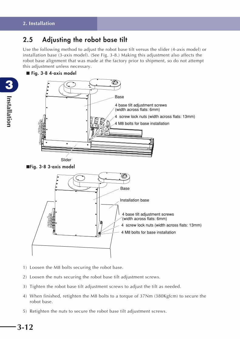
2.5 Adjusting the robot base tiltUse the following method to adjust the robot base tilt versus the slider (4-axis model) or installation base (3-axis model). (See Fig. 3-8.) Making this adjustment also affects the robot base alignment that was made at the factory prior to shipment, so do not attempt this adjustment unless necessary.
■ Fig. 3-8 4-axis model
4 base tilt adjustment screws (width across flats: 6mm)
4 screw lock nuts (width across flats: 13mm)
4 M8 bolts for base installation
Slider
Base
■Fig. 3-8 3-axis model
Base
Installation base
4 base tilt adjustment screws (width across flats: 6mm)
4 screw lock nuts (width across flats: 13mm)
4 M8 bolts for base installation
1) Loosen the M8 bolts securing the robot base.
2) Loosen the nuts securing the robot base tilt adjustment screws.
3) Tighten the robot base tilt adjustment screws to adjust the tilt as needed.
4) When finished, retighten the M8 bolts to a torque of 37Nm (380Kgfcm) to secure the robot base.
5) Retighten the nuts to secure the robot base tilt adjustment screws.
2. Installation

Installation
3
3-13
3. Protective bonding
WARNING
• Be sure to ground the robot and controller to prevent electrical shock.• Turn off the controller before grounding the robot.
The robot must be grounded as follows:
1) Provide a terminal marked "PE" for the protective conductor of the entire system and connect it to an external protective conductor. In addition, securely connect the ground terminal on the robot to the same protective conductor. (See Fig. 3-9.)
(Symbol 417-IEC-5019)
■ Fig. 3-9 4-axis model
Ground terminal
Ground symbol
3. Protective bonding

Installation
3
3-14
■ Fig. 3-9 3-axis model
Ground symbol
M4 ground terminal
2) An M4 machine screw with a spring washer and a tooth lock washer is attached to the ground terminal. Tighten the M4 machine screw by inserting it through the tooth lock washer, ring terminal and spring washer. (See Fig. 3-10.)
■ Fig. 3-10
Machine screw with spring washer
Ring terminal
Tooth lock washer
3) When the tool (end effector) uses an electrical device which, if it malfunctions, might make contact with the power supply, ground the end effector properly on your responsibility since no ground terminal is provided for such a device on the robot body.
4) For protective bonding on the robot body to comply with CE marking, follow the instructions on controller protective bonding explained in the "YAMAMA Robot Controller User's Manual or "CE Marking Supporting Supplement Manual".
5) Use a ground cable with a conductor wire cross section of at least 2.0mm2 and a length within 1 meter.On the 4-axis model, take out the ground cable through the cutout in the wiring box so that it will not interfere with the movable parts.
3. Protective bonding

Installation
3
3-15
4. Robot cable connectionFor details on connecting the robot cable to the controller, refer to Fig. 3-11 and the "YAMAHA Robot Controller User's Manual". After making connections, check the operation while referring to "6. Trial operation" in Chapter 1.
WARNING
• Before connecting the cables, check that there are no bends or breaks in the connector pins of the robot cable and that the cables are not damaged. Bent or broken pins or cable damage may cause malfunction of the robot.• Ensure that the controller is off before connecting the robot cable to the controller.• In the RCX142 controller, the MOTOR connectors XM and ZM, and YM and RM each have identical shapes. In addition, the PI connectors XY and ZR have identical shapes. Do not confuse these connectors when making connections. Wrong connections may result in malfunction and hazardous situations.• If the connector installation is inadequate or if there are contact failures in the pins, the robot may malfunction causing a hazardous situation. Reconfi rm that each connector is securely installed before turning on the controller.• To attach the PI connector securely, tighten the screws supplied with the robot.• Take caution not to apply an excessive load to the connectors due to stress or tension on the cables.• Lay out the cables so that they do not obstruct robot motion. Determine the robot work area in which the robot cables will not interfere with the load or workpiece picked up by the manipulator tip. If the robot cables interfere with the movable parts of the robot, the cables may be damaged causing malfunction and hazardous situations.• Lay out the robot cables so as to keep the operator or any other person from tripping on them. Bodily injury may result if someone trips on the cables.
Connect the robot cable to the controller as shown below.
■ Fig. 3-11 Robot cable connections
Robot cable
Connector on controllerConnector on robot side RCX142
XM
YM
ZM
RM
ROB I/OXY
ROB I/OZR
XM
YM
ZM
RM
XY
ZR
* On the 3-axis (X, Y and Z axes) model, it is not necessary to connect the RM connector, but always connect the ZR connector.
4. Robot cable connection

3-16
Installation
3
5. User wiring connector and user tubing
WARNING
• Always turn off the controller and shut off air supply before attempting wiring or tubing work. If air or power is supplied during this work, the robot may move erroneously causing a hazardous situation.• Be sure that user wiring and tubing installed utilizing the user wiring connectors and user tubing bulkhead unions do not interfere with robot motion, and do not become entangled with the robot, or swing about freely, as such conditions can damage the wiring or tubing and possibly cause malfunctions.• User wiring and tubing installed utilizing the user wiring connector and tubing bulkhead unions should be positioned so that they will not be in the way of the operator and other workers. Tripping over the wiring or tubing could result in falls and possible injury.
The disk handling robots are equipped with user signal wires and air tubes in the robot's machine harness. The table below shows the number of signal wires and air tubes available to users.
User wiring User tubing
4 wires φ4, 2 tubes
The specifications of user signal wires and air tubes are shown below. Always observe these specifications.
User Wiring
Rated voltage 30V
Allowable current 1.5A
Nominal cross-section area of conductor 0.1mm2
Shield None
User Tubing
Maximum pressure 0.58MPa (6Kgf/cm2)
Outer diameter × inner diameter φ4mm × φ2.5mm
FluidDry clean air not containing deteriorated compressor oil; air filter filtration 40µm or less
5. User wiring connector and user tubing

3-17
Installation
3
5.1 User wiring1) User wiring is provided on the arm side. (See Fig. 3-12.)
Make wiring to the end effector. When taking the user wires out of the hand holder (if provided), drill an additional hole in the cover of the hand holder.
2) A user wiring connector is provided on the controller side of the robot. (See Fig. 3-12.)On the 4-axis model, the user wiring connecter is located inside the wiring box.On the 3-axis model, the user wiring connector is located on the rear of the robot base.
■ Fig. 3-12
Screw
Cover
User wiring
Hand holder
With hand holderWithout hand holder
Arm side
Base
3-axis model
User wiring connector
Controller side
4-axis model
Tool attachment shaft
User wiring
User wiring connector
5. User wiring connector and user tubing

3-18
Installation
3
3) Signal wire connections in machine harnessPins 1 to 4 in the user wiring connector can be used.
4-axis model
Signal No. Color Connection No. Color Connector
User signal wire (Arm side)
1 Red 1 Red
I/O
(Controller side)
2 White 2 White
3 Yellow 3 Green
4 Blue 4 White
5
6
7
8
9
10
Cannot be used.
3-axis model
Signal No. Color Connection No. Color Connector
User signal wire (Arm side)
1 Red 1 Red
I/O
(Controller side)
2 White 2 White
3 Yellow 3 Yellow
4 Blue 4 Blue
5 Cannot be used.
5. User wiring connector and user tubing

3-19
Installation
3
4) On the 4-axis model, as shown in Fig. 3-13, crimp the wires (prepared by user) to the pins (supplied) using a crimping tool, and insert the pins into the connector (supplied). Then plug that connector into the user wiring connector. Take out the user wires through the cutout in the wiring box so that they will not interfere with the movable parts.On the 3-axis model, solder the user wires to the connector pins.
■ Fig. 3-13
User wiring connector (robot side)
User wiring connector (robot side)
Wiring prepared by user
Wiring prepared by user
Contact layout
Contact
Supplied connector
For 4-axis model
For 3-axis model
Lock
Pin No.
Connect
Rubber packing
InsulatorShell
: Guide key position
1234567
8910
1 2 3
4 5
WARNING
Securely attach the supplied connector into the user wiring connector on the robot side. If this connector comes loose or comes off, malfunction may result. The connector for the 4-axis model has lock tabs.
! CAUTION
Always use the pins and connector supplied with the robot. Using other types may result in contact failure.
For 4-axis modelSupplied connector for user wiring : SMR-10-V-B
Supplied pins for user wiring : SYM-001T-0.6
Manufacturer : JST Mfg. Co., Ltd.
For 3-axis modelSupplied connector for user wiring : NJW-16-5-PF-9
Manufacturer : MISUMI Corporation
5. User wiring connector and user tubing

3-20
Installation
3
5.2 User tubing1) Air tubes are installed in the arm side, and an O-ring groove formed at the port of
each air tube to allow direct attachment of a suction hand or gripper. Fit the supplied O-ring in this O-ring groove when using the air tube. When taking the user tubing 2 out of the hand holder (if provided), drill an additional hole in the cover of the hand holder and provide sealing, etc.
2) There are bulkhead unions for user tubing on the controller side of the robot.
■ Fig. 3-14 User tubing
User tubing 1O-ring groove
O-ring (S5)
Screw
User tubing 1 air tube
Hand holder
With hand holder
User tubing 2 ( 4 spare)
Coupler
Cover
Without hand holder Arm side
User tubing 1 ( 4)
3-axis model4-axis model
User tubing 2 ( 4)
Controller side
User tubing 1 ( 4)
User tubing 2 ( 4)
O-ring (S7)
User tubing 1
Tool attachment shaftO-ring groove
User tubing 2
3) To check the signal exchange and operation between the end effector and the controller or peripheral equipment after making user wiring and tubing connections, refer to "6. Trial Operation" in Chapter 1.
5. User wiring connector and user tubing

Installation
3
3-21
6. Attaching the end effector
6.1 AccelerationThe disk handling robot has a maximum load mass capacity of 200g (tool attachment shaft rotation's moment of inertia: 0.040kgf.cm.sec2). Therefore a mass and moment of inertia exceeding this level should never be applied to the tool attachment shaft. An excessive end effector moment of inertia can cause vibration and overload during operation of the X or Y axis or tool attachment shaft. This may also produce residual vibration during positioning.
! CAUTION
An excessive end effector moment of inertia can cause vibration and overload.Failure to comply with the maximum load mass capacity and moment of inertia will shorten the drive system life, and may result in damage and residual vibration during positioning.
6. Attaching the end effector

Installation
3
3-22
6.2 Equation for moment of inertia calculationUsually the load on the tool attachment shaft is not a simple form, and the calculation of the moment of inertia is not easy.As a method, the load is replaced with several factors that resemble a simple form for which the moment of inertia can be calculated. The total of the moment of inertia for these factors is then obtained.The objects and equations often used for the calculation of the moment of inertia are shown below. There is the following relation: J (kgf·cm·sec2) = I (kgm2) × 10.2.
1) Moment of inertia for material particleThe equation for the moment of inertia for a material particle that has a rotation center such as shown in Fig. 3-15 is as follows:This is used as an approximate equation when x is sufficiently larger than the object size.
■ Fig. 3-15
x
J= Wx g
2
(kgfcmsec2)
g : Gravitational acceleration (cm/sec2)m : Mass of material particle (kg)
... (Eq. 3.1)
I= mx2 (kgm2)
W : Weight of material particle (kgf)
2) Moment of inertia for cylinder (part 1)The equation for the moment of inertia for a cylinder that has a rotation center such as shown in Fig. 3-16 is given below.
■ Fig. 3-16
D
h
J=D h
32gWD8g
=4 2
(kgfcmsec2)
... (Eq. 3.2)
I=D h
32mD8
=4 2
(kgm2)
: Density (kg/m3, kg/cm3)g : Gravitational acceleration (cm/sec2)
m : Mass of cylinder (kg)W : Weight of cylinder (kgf)
6. Attaching the end effector

Installation
3
3-23
3) Moment of inertia for cylinder (part 2)The equation for the moment of inertia for a cylinder that has a rotation center such as shown in Fig. 3-17 is given below.
■ Fig. 3-17
h
D
2h
J=D h
16gW4g
=2
... (Eq. 3.3)
D4
h3
(2 2
+ )D4
h3
(2 2
+ )
I=D h
16m4
=2 D
4h3
(2 2
+ )D4
h3
(2 2
+ )
: Density (kg/m3, kg/cm3)g : Gravitational acceleration (cm/sec2)
m : Mass of cylinder (kg)W : Weight of cylinder (kgf)
(kgfcmsec2)
(kgm2)
4) Moment of inertia for prismThe equation for the moment of inertia for a prism that has a rotation center as shown in Fig. 3-18 is given as follows.
■ Fig. 3-18
1/2acb a
J=abc(a +b )
12gW(a +b )
12g=
2 2
... (Eq. 3.4)
2 2
I=abc(a +b )
12m(a +b )
12=
2 22 2
(kgfcmsec2)
(kgm2)
: Density (kg/m3, kg/cm3)g : Gravitational acceleration (cm/sec2)
m : Mass of prism (kg)W : Weight of prism (kgf)
5) When the object's center line is offset from the rotation center.The equation for the moment of inertia, when the center of the cylinder is offset by the distance "x" from the rotation center as shown in Fig. 3-19, is given as follows.
■ Fig. 3-19
h
Dx
J=D h
32g
WD8g
=
4
2
... (Eq. 3.5)
+D hx4g
2
+ Wxg
2
Center lineRotation
center
2
I=D h32
4
+D hx4
22 mD8
=2
mx2+
: Density (kg/m3, kg/cm3)g : Gravitational acceleration (cm/sec2)
m : Mass of cylinder (kg)W : Weight of cylinder (kgf)
(kgfcmsec2)
(kgm2)
6. Attaching the end effector

Installation
3
3-24
In the same manner, the moment of inertia of a cylinder as shown in Fig. 3-20 is given as follows:
■ Fig. 3-20
h
D
x
W4g
=
... (Eq. 3.6)
D4
h3
(2 2
+ )
Cneter line
J=D h
16g+
2 D4
h3
(2 2
+ )D h x
4g
2 2
+ Wxg
2
I=D h
16+
2 D4
h3
(2 2
+ )D h x4
2 2 m4
=D4
h3
(2 2
+ ) + mx2
(kgfcmsec2)
(kgm2)
In the same manner, the moment of inertia of a prism as shown in Fig. 3-21 is given as follows:
■ Fig. 3-21
a
c
bx
J=abc(a + b )
12g
W(a + b )12g
=
2
2
... (Eq. 3.7)
2
2
+abcxg
Wxg
+
2
2
Center line I=abc(a + b )
12
2 2
+ abcx2= m(a +b )12
2 2
+ mx2
m : Mass of prism (kg)W : Weight of prism (kgf)
(kgfcmsec2)
(kgm2)
6. Attaching the end effector

Installation
3
3-25
6.3 Example of moment of inertia calculationLet's discuss an example in which the chuck and workpiece are at a position offset by 10cm from the tool attachment shaft by a stay, as shown in Fig. 3-22.The moment of inertia is calculated with the following three factors, assuming that the load material is steel and its density ρ is 0.0078kg/cm3.
■ Fig. 3-22
10cm
2cm
2cm
1cm
1cm
2cm
2cm4cm
6cm
4cm
Tool attachment shaft
Stay
Chuck
Workpiece
1) Moment of inertia of the stay■ Fig. 3-23
12cm
2cm
2cm5cm
From Fig. 3-23, the weight of the stay (Ws) is given as follows:Ws = abc = 0.0078 12 2 2 = 0.37 (kgf)
The moment of inertia of the stay (Js) is then calculated from Eq. 3-7.
Js = 0.37 (122+22)+0.37 52
= 0.014 (kgfcmsec2)12 980 980
Center lineTool attachment shaft
6. Attaching the end effector

Installation
3
3-26
2) Moment of inertia of the chuck When the chuck form resembles that shown in Fig. 3-24, the weight of the chuck (Wc) is
■ Fig. 3-24
10cm2cm
6cm
4cm
Wc = 0.0078 2 4 6 = 0.37 (kgf)The moment of inertia of thechuck (Jc) is then calculatedfrom Eq. 3-7.
Jc = 0.37 (22+42)
12 980
0.37 102
+980
= 0.038 (kgfcmsec2)
Tool attachment shaft
3) Moment of inertia of workpieceWhen the workpiece form resembles that shown in Fig. 3-25, the weight of the workpiece (Ww) is
■ Fig. 3-25
10cm
4cm
2cm
Tool attachment shaftWw =
D2h =
0.0078 22 4
4 4
= 0.098 (kgf)
The moment of inertia of theworkpiece (Jw) is then calcu-lated from Eq. 3-5.
Jw=0.097 22
+ 0.097 102
8 980 980
= 0.010 (kgfcmsec2)
4) Total weightThe total weight (W) is calculated as follows:W = Ws + Wc + Ww = 0.84 (kgf)
5) Total moment of inertiaThe total moment of inertia (J) is then obtained as follows:J = Js + Jc + Jw = 0.062 (kgfcmsec2)
6. Attaching the end effector

Installation
3
3-27
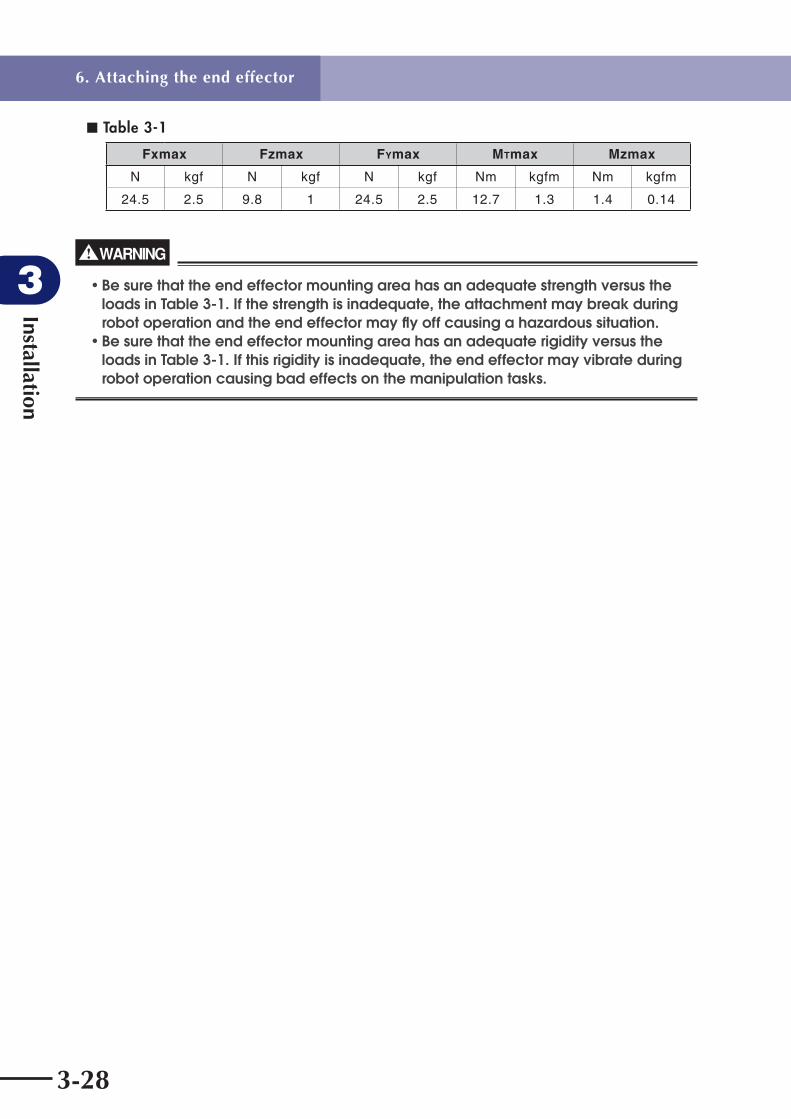
6.4 End effector attachment strength and rigidityThe end effector attachment must have adequate strength and rigidity, as well as gripping force to prevent positioning errors. Table 3-1 and Fig. 3-26 show the maximum load that can be applied to the end effector attachment during operation.
■ Fig. 3-26
End effector attachment prepared by user
End effector
FXmax
MZmax
MTmax
FZmax
FYmax
End effector attachment prepared by user
Hand holder
With hand holder
Without hand holder
FXmax
MZmax
MTmax
FZmax
FYmax
6. Attaching the end effector
Installation
3
3-28
■ Table 3-1
Fxmax Fzmax FYmax MTmax Mzmax
N kgf N kgf N kgf Nm kgfm Nm kgfm
24.5 2.5 9.8 1 24.5 2.5 12.7 1.3 1.4 0.14
WARNING
• Be sure that the end effector mounting area has an adequate strength versus the loads in Table 3-1. If the strength is inadequate, the attachment may break during robot operation and the end effector may fl y off causing a hazardous situation.• Be sure that the end effector mounting area has an adequate rigidity versus the loads in Table 3-1. If this rigidity is inadequate, the end effector may vibrate during robot operation causing bad effects on the manipulation tasks.
6. Attaching the end effector

Installation
3
3-29
6.5 Attaching the end effector
WARNING
Before attaching the end effector, be sure to turn off the controller.
1) Recommended methods for attaching the end effector are shown in Fig. 3-27 and Table 3-2 below.
■ Fig. 3-27
Suction hole
End effector prepared by user (suction tool, etc.)
Fastening bolt prepared by user
End effector hand holder prepared by user
M3 bolt (6 pcs) prepared by user
O-ring (supplied)
User wiring
Without hand holder
With hand holder
Internal air flow pathis required for suction
End effector prepared by user (suction tool, etc.)Internal air flow path is required for suction
O-ring (supplied)
User wiring
M3 bolt (6 pcs supplied)
Screw Hand support (supplied)
Suction tubing (user tubing 1)
Spare tubing (user tubing 2)
Suction hole
Hand holder
Cover (When taking user wires out of hand holder, drill an additional hole in this cover and provide sealing, etc.)
6. Attaching the end effector

Installation
3
3-30
■ Table 3-2
Bolt size Number of boltsTightening torque
Nm kgf • cm
M3 6 2.0 20
Recommended bolt : JIS B 1176, or equivalent Hex socket head bolt Strength class JIS B 1051 12.9, or equivalent
* In cases where the end effector cannot withstand the tightening torque for M3 bolts, reduce the tightening torque as needed. Use care, however, to avoid reducing the tightening torque to the point where the end effector may shift or fall off.
2) Refer to Fig. 3-28 for details on the end effector attachment section of the robot.
■ Fig. 3-28 Without hand holder
200
50
6.56.5
3131
5.65.6
11.3 11.3
3.3 3.3
AA
9.3
1
Cross section A-A
6-M3×0.5, depth: 10
O-ring S7 (2 pcs supplied) User tubing 1
User wiring (0.1mm2)Red : User wiring 1White : User wiring 2Yellow : User wiring 3Blue : User wiring 4
User tubing 2
6. Attaching the end effector

Installation
3
3-31
■ Fig. 3-28 With hand holder
3131
5.65.6
11.311.349
5
C
1
4060+0
.1+0
.2
29 0- 0.1
55.569
R30
2
11.3 11.3
6.5
6.5
1313
40 +0.10
40+0
.10
7.3
6- 3.5 thru-hole
B B
DD
A
Hand support
User wiring (0.1mm2)Red : User wiring 1White : User wiring 2Yellow : User wiring 3Blue : User wiring 4
User tubing 1
Set screw (3 pcs) for hand holder tilt adjustment
Set screw lock nut
User tubing 2 ( 4)Hand holder mounting bolt (3 pcs)
Details of AScale 1:1
Inside of hand holder with cover removed
Use
r ha
nd th
ickn
ess
mus
t no
t exc
eed
3mm
Hand
6-M3 bolt, length 8
Hand holder cover
Hand support
Cross section D-DScale 1:1
O-ring S5 (supplied)
Details of CScale 4:1
Cross section B-BScale 1:1
6-M3×0.5 thru-hole
WARNING
• When the end effector is mounted using the M3 bolts shown in Fig.3-28, be sure that the bolts are adequately tightened. If loose, the end effector could fl y off during robot operation, causing a hazardous situation.• Do not mount by any method other than that described above.
6. Attaching the end effector

Installation
3
3-32
3) If the end effector is attached in a way that it is not aligned with the straight forward direction of the tool attachment shaft, it moves along a path deviating from the straight forward direction. With the X-axis and Y-axis arms positioned as shown in Fig. 3-29, attach the end effector so its side surface is perpendicular to the arm side surface.
■ Fig. 3-29 Without hand holder
Align end effector by adjusting clearance gap between bolt and through-hole.
Tool holder prepared by userEnd effector
Fasten end effector so its side surface is perpendicular to arm side surface.
Position X-axis and Y-axis arms so their side surfaces are parallel with each other.
■ Fig. 3-29 With hand holder
End effector
Fasten end effector so its side surface is perpendicular to arm side surface.
Position X-axis and Y-axis arms so their side surfaces are parallel with each other.
Hand holder (Hand holder is positioned in advance so it is perpendicular to arm side surface.)
4) Refer to "6. Trial operation" in Chapter 1 to check the end effector motion.
6. Attaching the end effector

Installation
3
3-33
6.6 Adjusting the end effector tilt (when equipped with hand holder)Fig. 3-30 shows details of the hand holder section. The hand holder is fastened to the tool attachment shaft with three M4 bolts. To adjust the tilt of the hand attached to the hand holder, loosen those M4 bolts and then adjust the tightening of the M4 bolts and three M4 set screws. Do not tighten the set screws more than 1/2 turn after they reach the bottom of the screw holes. Doing so may cause the hand holder to come off the tool attachment shaft.After the adjustment is finished, tighten the M4 bolts to a torque of 4.5Nm (46Kgfcm) and lock the set screws with the nuts. Making this adjustment affects the hand holder's horizontal alignment that was made at the factory prior to shipment, so do not attempt this adjustment unless necessary.
■ Fig. 3-30 External view
3131
5.65.6
User tubing 2 ( 4)
11.311.349
6- 3.5 thru-holeUser tubing 1
M4 set screw (3 pcs) for hand holder tilt adjustment
Set screw lock nut
Hand holder mounting M4 bolt (3 pcs)
Details of AInside of hand holder with cover removed
D D
A
User wiring (0.1mm2)Red : User wiring 1White : User wiring 2Yellow : User wiring 3Blue : User wiring 4
6. Attaching the end effector
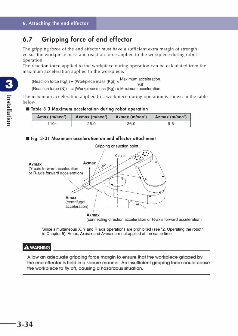
Installation
3
3-34
6.7 Gripping force of end effectorThe gripping force of the end effector must have a sufficient extra margin of strength versus the workpiece mass and reaction force applied to the workpiece during robot operation.The reaction force applied to the workpiece during operation can be calculated from the maximum acceleration applied to the workpiece.
(Reaction force (Kgf)) = (Workpiece mass (Kg)) × Maximum acceleration
(Reaction force (N)) = (Workpiece mass (Kg)) × Maximum acceleration9.8
The maximum acceleration applied to a workpiece during operation is shown in the table below.
■ Table 3-3 Maximum acceleration during robot operation
Amax (m/sec2) Axmax (m/sec2) AYmax (m/sec2) Azmax (m/sec2)
110r 26.0 26.0 9.6
■ Fig. 3-31 Maximum acceleration on end effector attachment
Gripping or suction point
Since simultaneous X, Y and R axis operations are prohibited (see "2. Operating the robot" in Chapter 5), Amax, Axmax and AYmax are not applied at the same time.
AYmax(Y-axis forward acceleration or R-axis forward acceleration)
AZmax
Amax(centrifugal acceleration)
AXmax(connecting direction acceleration or R-axis forward acceleration)
X-axis
r (m)
WARNING
Allow an adequate gripping force margin to ensure that the workpiece gripped by the end effector is held in a secure manner. An insuffi cient gripping force could cause the workpiece to fl y off, causing a hazardous situation.
6. Attaching the end effector

3-35
Installation
3
7. Working envelope and mechanical stopper positions for maximum working envelopeFor details concerning the robot's working envelope and the operation limit mechanical stopper positions, see "2. External View and Dimensions" in Chapter 7.
1) X-axis and Y-axisDo not attempt operation outside the working envelope.Due to origin adjustments, the origin positions may differ slightly from those shown in the external view. The mechanical stopper positions may vary somewhat depending on the parts machining accuracy, etc.
2) Tool attachment shaftThe tool attachment shaft movement is indirectly restricted by the Y-axis mechanical stoppers.
3) Z-axisThe Z-axis has mechanical stoppers at the upper and lower ends.The manipulator lowers approximately 3mm from near the origin position during return to origin by stroke end detection.
4) R-axisThe R-axis has a mechanical stopper at its stroke end.The manipulator moves approximately 5mm to the mechanical stopper from near the origin position during return to origin by stroke end detection.
5) OthersDepending on the parts machining accuracy and assembly condition, the X and Y axis arms and tool attachment shaft may not be completely aligned in a straight line even when the arms are fully extended.
6) A urethane damper is installed to absorb the shock when an impact occurs with the mechanical stopper, so a certain amount of overrun occurs when the robot strikes the mechanical stopper. Use caution and take overrun into account since the end effector may interfere with the robot body and peripheral equipment or the robot body may interfere with the peripheral equipment.Maximum overrun amounts are listed below (normal operation at maximum speed). When the robot strikes the X-axis or Y-axis mechanical stopper or another object, or when the end effector collides with an object, the X-axis or Y-axis speed reduction gears might be locked while being meshed if the collision impact is large. Belt slippage could also occur inside the robot arms. If this occurs, please contact a YAMAHA sales office or dealer.
■ Table 3-4
X-axis Y-axis Z-axis R-axis
Forward end Backward end Upper end Lower end Forward end Backward end
2.5° 2mm 2mm 2mm 2mm 2mm 2mm
Note: Here, ° (deg.) is the overrun angle at the X-axis joint.
7. Working envelope and mechanical stopper positions for maximum working envelope

Installation
3
3-36
8. Base suction tubeCouplers for suction in the robot base and arms are located on the rear of the robot base.A suction rate of 60 Nl/min is required. Refer to "1. Basic specifications" in Chapter 7 for information about the cleanliness degree during suction.
■ Fig. 3-32 4-axis model
Suction coupler ( 12×2)
■Fig. 3-32 3-axis model
Suction coupler ( 12×2)
8. Base suction tube

Chapter 4 Adjustment
Contents
1. Overview 4-1
2. Safety precautions 4-1
3. Adjusting the origin 4-2
3.1 Absolute reset method 4-3
3.1.1 Sensor method (X-axis and Y-axis) 4-3
3.1.2 Stroke end method (Z-axis and R-axis) 4-3
3.2 Machine reference 4-4
3.3 Absolute reset procedures 4-5
3.3.1 Sensor method (X-axis and Y-axis) 4-5
3.3.2 Strike end method (Z-axis and R-axis) 4-8
3.4 Removing the robot covers 4-9
3.5 Adjusting the machine reference 4-10
3.5.1 Adjusting the X-axis machine reference 4-10
3.5.2 Adjusting the Y-axis machine reference 4-12
3.5.3 Adjusting the Z-axis machine reference 4-14
4. Setting the soft limits 4-16
5. Affixing stickers for movement directions and axis names 4-17
6. Adjusting the timing belt tension 4-19
6.1 Adjusting the X-axis, Y-axis, and Z-axis motor belt tension 4-19
6.2 Adjusting the timing belt tension for the X-axis and Y-axis arms 4-24
6.2.1 Adjusting the X-axis arm belt 4-24
6.2.2 Adjusting the Y-axis arm belt 4-25
7. X-axis and Y-axis arm alignment 4-27


Adjustm
ent
4
4-1
1. Overview
1. Overview YAMAHA robots have been completely adjusted at the factory or by the sales representative before shipment, including the origin position adjustment. If the operating conditions are changed and the robot must be adjusted, then follow the procedures described in this chapter.
2. Safety precautions
(1) Read and understand the contents of this chapter completely before attempting to adjust the robot.
(2) Place a conspicuous sign indicating the robot is being adjusted, to prevent others from touching the controller switch, programming unit or operation panel.
(3) If a safety enclosure has not yet been provided right after installation of the robot, rope off or chain off the movement area around the manipulator in place of a safety enclosure, and observe the following points.
q Use stable posts which will not fall over easily.
w The rope or chain should be easily visible by everyone around the robot.
e Place a conspicuous sign prohibiting the operator or other personnel from entering the movement area of the manipulator.
(4) To check operation after adjustment, see "6. Trial operation" in Chapter 1.

Adjustm
ent
4
4-2
3. Adjusting the origin
3. Adjusting the origin The disk handling robot uses absolute position sensors. The origin position (zero-pulse position) is set by performing an absolute reset (return to origin). Once an absolute reset has been performed, it need not be performed again at the next power ON. An absolute reset is required, however, under the conditions shown below. Note that the robot is in condition "c" when shipped from the factory, and an absolute reset is therefore required after installation. For details regarding absolute resets, refer to "11.8 Absolute reset" in Chapter 4 of the "YAMAHA Robot Controller RCX142 Series User's Manual".
a. After an absolute-related error occurs at an axis.
b. After a low-voltage condition is detected in the absolute battery installed outside the controller.
c. After the cable that connects the controller to the robot is disconnected. (Shipping status).
d. After robot generation is changed.
e. After parameters are initialized.
f. After "Origin shift", "Origin method", "Origin direction" or " "Motor Direction" of the axis parameter data is changed.
g. After motor replacement (after disconnecting the motor cable).
h. After writing all data files (data with "ALL" extension name) or parameter files (data with "PRM" extension name) to the controller via the RS-232C interface.
This chapter explains the absolute reset procedures.
! CAUTION
• If any of the above cases (a to h) occur after installing the robot, absolute reset must be performed again. The robot must be moved to its origin position in order to perform an absolute reset. Install the robot in a location where there is no interference with peripheral equipment, etc., after the origin position (fi xed) setup is completed. • After performing an absolute reset, move the robot to a known point to check whether the origin position is correctly set. When doing this check, move the robot at the slowest possible speed.
The X-axis and Y-axis use a "search method (sensor method)" to detect the origin positions, while the Z-axis uses a "stroke end method" that allows the mechanical unit to strike the lower-end mechanical stopper to detect the origin position. The R-axis (travel axis) also uses the same "stroke end" method to detect the origin position. For the R-axis details, refer to the F17 single-axis robot described in the "FLIP-X Series User's Manual".

Adjustm
ent
4
4-3
3. Adjusting the origin
3.1 Absolute reset method
3.1.1 Sensor method (X-axis and Y-axis)In the sensor method, the target axis is automatically operated for absolute reset, and the absolute reset is performed at the position where the proximity sensor provided on the target axis detects the detection point (dog). The absolute reset in the sensor method can be executed with the teaching pendant (MPB), RS-232C communication, and dedicated input.
WARNING
Serious injury might occur from physical contact with the robot during operation. Never enter within the robot movement range during absolute reset.
! CAUTION
The origin cannot be detected in any axis which is not positioned on the plus side from the origin (See Fig. 4-3 (a) to (d).) before starting the return-to-origin operation. (Factory setting at shipment.) In this case, press the STOP key to interrupt the return-to-origin operation, move the target axis to the plus side of the origin, and reperform the return-to-origin operation. If the return-to-origin operation is not interrupted, the robot will continue the operation and may collide with the mechanical stopper or a peripheral device.
3.1.2 Stroke end method (Z-axis and R-axis)In the stroke end method, absolute reset is performed at a position slightly backed off from the stroke end, after the mechanical unit contacts the mechanical stopper and stroke end is detected.
WARNING
Serious injury might occur from physical contact with the robot during operation. Never enter within the robot movement range during absolute reset.

Adjustm
ent
4
4-4
3.2 Machine reference The disk handling robot uses a resolver as the position sensor. The resolver provides 4 absolute reset positions per motor turn. When performing an absolute reset by the sensor method, the origin position is set at one of those absolute reset positions located just after the point where the origin sensor reacts to the dog (origin signal detected). The machine reference means the position relationship of the position where the robot detects the origin signal to the position where the absolute reset can be performed soon after detection. (See Fig. 4-1.) The machine reference is expressed in the ratio of interval A to interval B shown in Fig. 4-1. Interval A is the minimum distance between the positions where absolute reset can be performed and interval B is the distance between the position where the origin signal is detected and the position where absolute reset can be performed soon after the origin signal detection. The machine reference value is displayed on the optional MPB screen (unit: %).
Machine reference value = B/A × 100 (%)
! CAUTION
The machine reference must be adjusted within a specifi ed range to keep the repeatability precision of the absolute reset position. (The machine reference is factory-adjusted, and does not normally require further adjustment.) If the origin position is changed, the machine reference must be readjusted.For information on how to adjust the machine reference, see "3.4 Adjusting the machine reference" in Chapter 4. When the temperature of the robot joint sections is high immediately after the robot has been operated, the machine reference value might be outside the specifi ed range (40 to 60%). When checking or adjusting the machine reference value, always make sure that the temperature of the robot joint sections has returned to room temperature.
Recommended machine reference value: 40 to 60%
■ Fig. 4-1 Machine reference
Origin signal detection
Origin signal
Resolver
One motor revolution
BA
ON
OFF
Positions where absolute reset can be performed
■ Fig. 4-2 Machine reference value display on MPB screen
MANUAL ]J0H0S[ ]GM[ %05SBA .TSR>
Machine reference (%)
M1= 52
M4= 66
M2= 57 M3= 52
M1 M2 M3 M4 M5
R-axis X-axis Z-axis
MPB
Y-axis
3. Adjusting the origin

Adjustm
ent
4
4-5
3.3 Absolute reset procedures
3.3.1 Sensor method (X-axis and Y-axis)
WARNING
Serious injury might occur from physical contact with the robot during operation. Never enter within the robot movement range during absolute reset.
The operation procedure using the MPB is described below. (Press the ESC key on the MPB if you want to return to the preceding step.) Refer to the "YAMAHA Robot Controller User's Manual" for how to operate the robot controller.
1) Check that no one is inside the safeguard enclosure and then turn on the controller.
2) Place a sign indicating the robot is being adjusted, to keep others from touching the controller switch or operation panel.
3) Set the controller to MANUAL mode, if not in MANUAL mode.
4) Press the F13 (LOWER + F3) key to select "RST. ABS".
5) Select the axis for absolute reset. (X-axis: M1, Y-axis: M2)To perform absolute reset on all axes, select "ALL" with the F11 (LOWER+F1) key.
! CAUTION
When performing absolute reset on all axes, the Z-axis of the stroke end method lowers following the Y-axis absolute reset, and then the R-axis of the stroke end method detects the origin following the X-axis absolute reset (default setting). Be careful that your fi ngers do not get pinched or crushed by axis movement.
6) Check that the X and Y axes for absolute reset are positioned at the plus side of the origin. (See Fig. 4-3 (a) to (d).)If it is not at the plus side, then press the jog key to move the target axis to the plus side.
7) Since the message "Reset ABS encoder OK?" appears, check that there are not any obstacles in the robot movement range, and press the F4 (YES) key.
8) After the absolute reset is completed, check that the machine reference value displayed on the MPB is between 40 and 60 (recommended range).If the machine reference value is outside the recommended range, then the next absolute reset may not be properly performed. In this case, adjust the machine reference by referring to "3.5 Adjusting the machine reference".
3. Adjusting the origin

Adjustm
ent
4
4-6
■ Fig. 4-3 (a)
X-axis plus directionX-axis return-to-origin direction
R-axis
X-axis origin is the position where hand's plus direction (straight forward direction) matches R-axis (travel axis) plus direction.
X-axis arm direction does not correspond to X-axis direction because X-axis arm also produces Y-axis motion.
X-axis position is on hand's plus direction (straight forward direction).(This is the position where X-axis moves 90° in plus direction.)
■ Fig. 4-3 (b)
Y-axis plus direction X-axis and Y-axis origin positions
Y-axis return-to-origin direction
3. Adjusting the origin
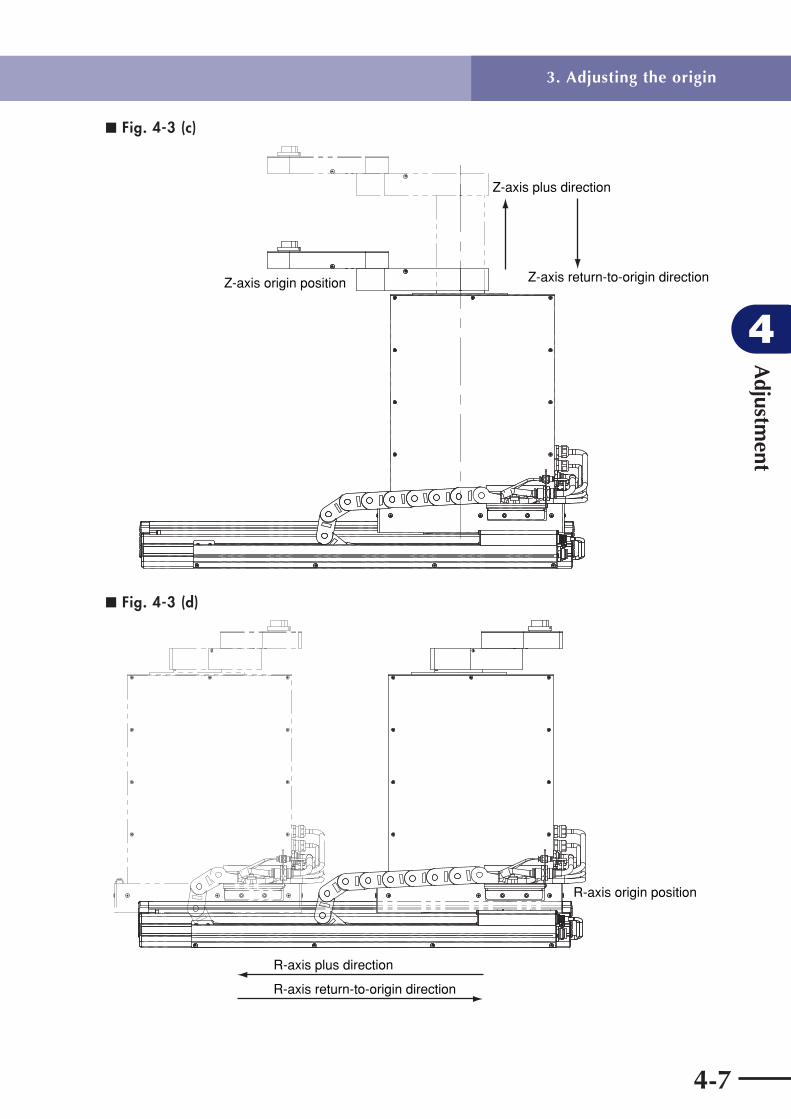
Adjustm
ent
4
4-7
■ Fig. 4-3 (c)
Z-axis origin position
Z-axis plus direction
Z-axis return-to-origin direction
■ Fig. 4-3 (d)
R-axis origin position
R-axis return-to-origin direction
R-axis plus direction
3. Adjusting the origin

Adjustm
ent
4
4-8
3.3.2 Strike end method (Z-axis and R-axis)
WARNING
Serious injury might occur from physical contact with the robot during operation. Never enter within the robot movement range during absolute reset.
The operation procedure using the MPB is described below. (Press the ESC key on the MPB if you want to return to the preceding step.) Refer to the "YAMAHA Robot Controller User's Manual" for how to the robot controller. For the R-axis (travel axis) details, refer to the F17 single-axis robot described in the "FLIP-X Series User's Manual".
1) Check that no one is inside the safeguard enclosure and then turn on the controller.
2) Place a sign indicating the robot is being adjusted, to keep others from touching the controller switch or operation panel.
3) Set the controller to MANUAL mode, if not in MANUAL mode.
4) Press the F13 (LOWER + F3) key to select "RST. ABS".
5) Select the axis for absolute reset. (Z-axis: M3, R-axis: M4)
6) Since the message "Reset ABS encoder OK?" appears, check that there are not any obstacles in the robot movement range, and press the F4 (YES) key.
7) After the absolute reset is completed, check that the machine reference value for stroke-end method adjustment displayed on the MPB is within the allowable absolute reset range (40 to 60).
! CAUTION
Use the following procedure to display the machine reference value for stroke-end method adjustment. When adjusting the machine reference, always use this procedure to check the machine reference value for adjustment.
q Press the MODE key.
w Press the F3 key to enter MANUAL mode.
e Press the F13 (LOWER + F3) key to select "RST.ABS".
r After the Z-axis absolute reset is completed, press the F10 (UPPER + F5). The machine reference value for adjustment is then displayed in percent (%).
If the machine reference value is outside the allowable absolute reset range, then the next absolute reset may not be properly performed. In this case, adjust the machine reference by referring to "3.5 Adjusting the machine reference".
3. Adjusting the origin

Adjustm
ent
4
4-9
3.4 Removing the robot covers
WARNING
Before removing the robot covers, be sure to turn off the controller power.
Refer to the figures below when removing the covers to adjust soft limits or belt tension.For the R-axis (travel axis) details, refer to the F17 single-axis robot described in the "FLIP-X Series User's Manual".
■ Fig. 4-4 Removing the robot covers
M3×6 flat-head screw (4 pcs)
Travel axis cover
M4×8 flat-head screw (4 pcs)
Slider side cover
M4×8 screw (7 pcs)
M4×8 flat-head screw (2 pcs)
Base side cover
M3×6 flat-head screw (12 pcs)
X-axis arm coverRemove cover while raising Z-axis.
M3×6 flat-head screw (4 pcs)
Y-axis arm coverPull cover up about 1mm and then turn it around tool attachment shaft.
M4×8 screw (7 pcs)
Base side cover
M3×6 flat-head screw (12 pcs)
Slider side cover
3. Adjusting the origin

Adjustm
ent
4
4-10
3.5 Adjusting the machine reference
! CAUTION
If any machine reference is adjusted, the origin position may change. Before the adjustment, mark off the reference mark at the current origin position on the robot body. After the machine reference is adjusted, be sure to check that the origin position has not deviated. The point data must be set again if the origin position is changed after machine reference adjustment.
3.5.1 Adjusting the X-axis machine reference The adjustment method for the X-axis machine reference is as follows.
1) Prepare the necessary tools. • Hex wrench set • Phillips screwdrivers
2) Check that no one is inside the safety enclosure and then turn on the controller.
3) Perform an absolute reset from outside the safety enclosure. See "3.3.1 Sensor method (X-axis and Y-axis)" about the absolute reset method.
4) The following adjustment is required if a machine reference outside the 40 to 60 range (recommended range) is displayed on the MPB after absolute reset. For details on machine reference, see "3.2 Machine reference".
5) Place a sign indicating that the robot is being adjusted in order to keep others from operating the controller or operation panel.
6) Turn off the controller and enter the safety enclosure.
7) Remove the base cover. See "3.4 Removing the robot covers" for this procedure. At this time, avoid touching the X-axis arm to prevent the origin position from deviating.
3. Adjusting the origin

Adjustm
ent
4
4-11
8) Mark off the reference mark at the current origin position on the X-axis joint area of the robot. (See Fig. 4-4.) At this time, avoid touching the X-axis arm to prevent the origin position from deviating.
■ Fig. 4-4
2 M4 bolts Dog Mark
Origin position mark
Sensor plateSensor
BB
AA
9) Make a reference mark at the sensor plate position.
10) Loosen the M4 bolts and move the sensor plate as described below, then tighten the bolts. When "machine reference" < 40%: Move sensor plate in direction "A". When "machine reference" > 60%: Move sensor plate in direction "B". As an approximate guide, a 2.4mm movement equals 100%.
11) Go out of the safety enclosure, and check that no one is inside the safety enclosure. Then turn on the controller.
12) Perform an absolute reset from outside the safety enclosure.
13) After the absolute reset is completed, read the machine reference value displayed on the MPB.
14) The machine reference adjustment is complete when the machine reference is within the 40 to 60 range (recommended range). Turn off the controller and then reattach the base cover. If the machine reference is still outside the recommended range, readjust it by repeating the procedure from step 9).
3. Adjusting the origin

Adjustm
ent
4
4-12
3.5.2 Adjusting the Y-axis machine reference The adjustment method for the Y-axis machine reference is as follows.
1) Prepare the necessary tools. • Hex wrench set • Phillips screwdrivers
2) Check that no one is inside the safety enclosure and then turn on the controller.
3) Perform an absolute reset from outside the safety enclosure. See "3.3.1 Sensor method (X-axis and Y-axis)" about the absolute reset method.
4) The following adjustment is required if a machine reference outside the 40 to 60 range (recommended range) is displayed on the MPB after absolute reset. For machine reference details, see "3.2 Machine reference".
5) Place a sign indicating that the robot is being adjusted in order to keep others from operating the controller or operation panel.
6) Turn off the controller and enter the safety enclosure.
7) Mark off the reference mark at the current origin position on the Y-axis joint area of the robot. (See Fig. 4-5.) At this time, avoid touching the Y-axis arm to prevent the origin position from deviating.
■ Fig. 4-5
X-axis
Y-axis drive unit
Mark
Sensor plate M4 bolt (2 pcs)
Mark
Window
Y-axis sensor
A
B
8) Remove the base cover. See "3.4 Removing the robot covers" for this procedure.
9) Make a reference mark at the sensor plate position.
3. Adjusting the origin

Adjustm
ent
4
4-13
10) Loosen the M4 bolts and move the sensor plate as described below, then tighten the bolts. When "machine reference" < 40%: Move sensor plate in direction "A". When "machine reference" > 60%: Move sensor plate in direction "B". As an approximate guide, a 1.7mm movement equals 100%.
11) Go out of the safety enclosure, and check that no one is inside the safety enclosure. Then turn on the controller.
12) Perform an absolute reset from outside the safety enclosure.
13) After the absolute reset is completed, read the machine reference value displayed on the MPB.
14) The machine reference adjustment is complete when the machine reference is within the 40 to 60 range (recommended range). Turn off the controller and then reattach the base cover. If the machine reference is still outside the recommended range, readjust it by repeating the procedure from step 9).
3. Adjusting the origin

Adjustm
ent
4
4-14
3.5.3 Adjusting the Z-axis machine referenceThe Z-axis origin position is fixed at the lower end of the Z-axis stroke and cannot be changed. The Z-axis machine reference value is preadjusted before shipment and does not need to be adjusted in normal operation.However, if for some reason the machine reference value goes outside the allowable absolute reset range (40 to 60), adjust with the procedure below.To check the machine reference value, refer to step 13).
WARNING
Fingers may get caught between the drive pulley and belt, causing injury. Before touching those parts, always turn off the controller and perform the work carefully.
! CAUTION
Adjusting the machine reference will usually change the origin position. The point data must be set again after the machine reference adjustment.
1) Check that no one is inside the safety enclosure and then turn on the controller.
2) Place a sign indicating that the robot is being adjusted in order to keep others from operating the controller or operation panel.
3) Before beginning the following steps, always perform a Z-axis absolute reset. The Z-axis may otherwise slide down.Perform an absolute reset on the Z-axis.See "3.3.2 Stroke end method (Z-axis and R-axis)" about the Z-axis absolute reset method.
4) Turn off the controller.
5) Enter the safety enclosure.
6) Remove the base cover.See "3.4 Removing the robot covers" for this procedure.
7) Hold the X-axis arm by hand as it moves down about 3mm after the Z-axis motor is removed.Be careful that your fingers do not get pinched. (See Fig. 4-6.)
3. Adjusting the origin

Adjustm
ent
4
4-15
■ Fig. 4-6
2.5m
m
Z-axis lower-end damperPlate
Belt
Pulley on ball screw
Belt
M5 bolt (3 pcs)
Motor pulley
Z-axis motorZ-axis motor plate
* Hold X-axis arm by hand as it moves down about 3mm after Z-axis motor is removed. Be careful that your fingers do not get pinched.
8) Remove the M5 bolts securing the Z-axis motor plate and then remove the Z-axis motor.
9) While holding the arms, install the Z-axis motor plate so the distance from the Z-axis lower-end damper to the bottom of the plate is 2.5mm. At this point, make sure that the belt is properly engaged with the motor pulley and ball screw pulley.
10) After reassembling the Z-axis motor, adjust the timing belt tension. To adjust the timing belt tension, see "6.1 Adjusting the X-axis, Y-axis, and Z-axis motor belt tension".
11) Go out of the safety enclosure.
12) Check that no one is inside the safety enclosure. Then turn on the controller.
13) Perform an absolute reset on the Z-axis. After the absolute reset is completed, check that the machine reference value for stroke-end method adjustment is within the allowable absolute reset range (40 to 60).
! CAUTION
Use the following procedure to display the machine reference value for stroke-end method adjustment. When adjusting the machine reference, always use this procedure to check the machine reference value for adjustment.
q Press the MODE key.
w Press the F3 key to enter MANUAL mode.
e Press the F13 (LOWER + F3) key to select "RST.ABS".
r After the Z-axis absolute reset is completed, press the F10 (UPPER + F5). The machine reference value for adjustment is then displayed in percent (%).
If the machine reference value for adjustment is still outside the allowable absolute reset range (40 to 60), repeat from step 7) onward so it is within the allowable range.
14) Reattach the cover.
3. Adjusting the origin

Adjustm
ent
4
4-16
4. Setting the soft limitsIn the disk handling robot, the working envelope during manual and automatic operation can be limited by setting the plus soft limit [pulses] and minus soft limit [pulses] on each axis. The origin point ( 0 [pulses] ) is used as the reference to set the soft limits. The working envelope can be limited by specifying the number of pulses from the 0 pulse position. Refer to the "YAMAHA Robot Controller RCX142 Series User's Manual" for further details. Also refer to "2. External view and dimensions" in Chapter 7 for the robot's working envelope. When performing actual checks of the soft limit settings, operate the robot manually from outside the safety enclosure.
Soft limit settings on each axis
The factory-set soft limits are for the maximum working envelope. Follow the procedure below to set soft limits that prevent interference with peripheral equipment (but are within the maximum working envelope). When the servo power is off, it is difficult to move the X and Y axes because of their structures and the Z-axis because of its weight. Manually move each axis with the following procedure. See "3. Creating point data, direct teaching, and external forces to arms" in Chapter 5 for more details.
1) Place a sign indicating that the robot is being adjusted in order to keep others from operating the controller or operation panel.
2) Check that no one is inside the safety enclosure, and then turn on the controller.
3) Enter the safety enclosure while holding the MPB. Keep clear of the robot's working envelope.
4) Manually move each axis to positions just prior to interference with peripheral equipment, then make a note of the plus-direction and minus-direction pulses for each axis displayed on the MPB screen.
5) Set the soft limits using the pulses for each axis that were noted in step 3) above. This software limit setting must be made from outside the safety enclosure. Refer to the "YAMAHA Robot Controller RCX142 Series User's Manual" for further details on soft limit settings.
6) Unlike the SCARA robots, the soft limits cannot be set on an orthogonal coordinate system. Point displays based on an orthogonal coordinate have no meaning, and such a coordinate system should not be used.
4. Setting the soft limits

4-17
Adjustm
ent
4
5. Affixing stickers for movement directions and axis names The robot comes packed with stickers (self-adhesive labels) showing movement directions and axis names as shown in Fig. 4-7. Using the following procedure, attach these stickers in conspicuous points on the robot after installing peripheral equipment.
■ Fig. 4-7
A BX YZ R
Movement direction and axis name stickers
1) Turn off the controller.
2) Place a sign indicating the robot is being adjusted, to keep others from operating the controller switch.
3) Enter the safety enclosure.
4) Affix the axis name stickers and movement direction stickers in prominent positions on each of the robot arms. Use a cloth moistened with alcohol to remove grease from the surface where you will affix the stickers. After the surface is completely dry, affix the stickers securely. (See Fig. 4-8) The direction in which the Y-axis joint rotates to move the tool attachment shaft straight forward (plus direction) is the plus direction. (Example 1) Please note that the X-axis also rotates while the tool attachment shaft moves straight forward.When the end effector is long as shown in example 2, you may affix stickers to it along the straight forward direction of the tool attachment shaft.
WARNING
Align the direction of movement stickers with the jog direction and affi x them correctly. Affi x each axis name sticker on the correct axis. Affi xing the sticker at a wrong location may cause faulty operation and hazardous situations.
5. Affixing stickers for movement directions and axis names

4-18
Adjustm
ent
4
■ Fig. 4-8 Example 1
Y− +
X− +
+
−
Z
−+R
■ Fig. 4-8 Example 2
Y + –
5. Affixing stickers for movement directions and axis names

Adjustm
ent
4
4-19
6. Adjusting the timing belt tensionIf the timing belt becomes slack, use the following procedure to give proper tension to the belt.
WARNING
• The motor and speed reduction gear casing are extremely hot after automatic operation, so burns may occur if these are touched. Before touching these parts, turn off the controller, wait for a while and check that the temperature has cooled.• Injury can occur if hands or fi ngers are squeezed between the drive pulley and belt. Always turn off the controller and use caution when handling these parts.
! CAUTION
Since a positional shift occurs after adjusting the belt tension, it is necessary to make absolute reset and point data setting again.
6.1 Adjusting the X-axis, Y-axis, and Z-axis motor belt tension1) Prepare the necessary tools.
• Push-pull scale• Stay (See Fig. 4-10. This stay should be prepared by the user.)• Hex wrench set• Phillips screwdrivers• Scale
2) When adjusting the X-axis or Y-axis belt tension, position the X-axis at the front base and the Z-axis at a stroke position of 130mm (106496 pulses). When adjusting the Z-axis belt tension, move the Z-axis to its origin position. If adjustment is made with the Z-axis not at the origin position, the Z-axis may slides down causing a hazardous situation.Then turn off the controller.
3) Place a sign indicating the robot is being adjusted, to keep others from operating the controller switch.
4) Enter the safety enclosure.
5) Remove the base cover.See "3.4 Removing the robot covers" for this procedure.
6) Adjust the belt tension by two people as follows.Using the push-pull scale, one person applies a load perpendicular to the middle of the belt. The other person checks the slack of the belt. (See Fig. 4-9, Fig. 4-10, Fig. 4-11, Fig. 4-12 and Fig. 4-13.)At the Y-axis belt, the Fig. 4-12 "part 1" must be removed from "part 2" in order to use the push-pull scale to measure the tension.An easy way to check the belt tension is to press a finger against the belt through the inspection window. There should be some give in the belt when pressed. If there is no give in the belt, the belt is too tight. Use this as a reference for belt tension.
6. Adjusting the timing belt tension

Adjustm
ent
4
4-20
■ Fig. 4-9 Belt tension adjustment
Push-pull scale
SlackLoad
PulleyPulley Belt
■ Fig. 4-10 Stay (example)
5Belt
Push-pull scale
Nut
Nut
Stay
Metal plate 3.2mm thickness
25
55
10
Hole
15
■ Fig. 4-11 X-axis
Increase tensionIncrease tension
Reduce tension
X-axis motor
Plate
Z-axis motor Pulley
M5 bolt (4 pcs)
Pulley
X-axis motor belt
Front base
Y-axis motor belt
6. Adjusting the timing belt tension

Adjustm
ent
4
4-21
■ Fig.4-12 Y-axis
Inspection windowPulley Plate
Part 1
Part 2
Y-axis motor belt
Pulley
Reduce tension
Increase tension
M3 bolt (4 pcs)
Y-axis motor
■ Fig. 4-13 Z-axis
Reduce tension
Increase tension
Reduce tension
Increase tension
Z-axis motor
M5 bolt (3 pcs)
Plate
Pulley
Z-axis motor belt
Pulley
6. Adjusting the timing belt tension

Adjustm
ent
4
4-22
7) Belt tension adjustment is not required if the load producing the Table 4-1 "Slack" is within the "Load" range in Table 4-1. If outside the load range, adjust using the procedure described below.
■ Table 4-1
Location Load (N) Load (kgf) Slack (mm)
X-axis Belt 6.1 to 7.4 0.62 to 0.75 1.92
Y-axis Belt 2.7 to 4.1 0.28 to 0.42 0.74
Z-axis Belt 5.7 to 6.3 0.58 to 0.64 4.4
■ Table 4-2 Tightening torque
Axis Bolt size Tightening torque (kgf . cm) Tightening torque (N . m)
X M5 92 9.0
Y M3 20 2.0
Z M5 92 9.0
(1) X-axis belt adjustment
1. Loosen the bolt q shown in Fig. 4-11. Never remove it.
2. If the load producing the slack specified in Table 4-1 (step 6) above) is smaller than the specified range, move the X-axis motor plate in the direction increasing the tension. If the load is greater than that range, move it in the direction reducing the tension. Then, retighten the bolt.
3. Recheck the belt tension using the same procedure in step 6). When the load applied to produce the specified slack is within the specified load range of Table 4-1, the adjustment is okay. If not, repeat the above procedure from steps 1 to 3.
(2) Y-axis belt adjustment
1. Loosen the bolts w shown in Fig. 4-11 and Fig. 4-12. Never remove them.
2. If the load producing the slack specified in Table 4-1 (step 6) above) is smaller than the specified range, move the Y-axis motor plate in the direction increasing the tension. If the load is greater than that range, move it in the direction reducing the tension. Then, retighten the bolts.
3. Recheck the belt tension using the same procedure in step 6). When the load applied to produce the specified slack is within the specified load range of Table 4-1, the adjustment is okay. If not, repeat the above procedure from steps 1 to 3.
(3) Z-axis belt adjustment
1. Loosen the bolts e shown in Fig. 4-13. Never remove them.
2. If the load producing the slack specified in Table 4-1 (step 6) above) is smaller than the specified range, move the Z-axis motor plate in the direction increasing the tension. If the load is greater than that range, move it in the direction reducing the tension. Then, retighten the bolts.
3. Recheck the belt tension using the same procedure in step 6). When the load applied to produce the specified slack is within the specified load range of Table 4-1, the adjustment is okay. If not, repeat the above procedure from steps 1 to 3.
6. Adjusting the timing belt tension

Adjustm
ent
4
4-23
8) After adjustment is complete, tighten the bolts q, w or e to the torque specified in Table 4-2.
9) Attach the base cover.
10) Go outside the safety enclosure.
11) Check that no one is inside the safety enclosure, and then turn on the controller.
6. Adjusting the timing belt tension

Adjustm
ent
4
4-24
6.2 Adjusting the timing belt tension for the X-axis and Y-axis arms The timing belts used in the X and Y axis arms have almost no stretch. Therefore, the belt tension will be appropriate as long as the tensioners (See Fig. 4-14 and Fig. 4-15) are not moved. If for some reason their positions have moved, adjust the belt tension with the following procedure.
6.2.1 Adjusting the X-axis arm belt
1) Prepare the necessary tools. • Hex wrench set • Phillips screwdrivers • 7mm wrench
2) Turn off the controller.
3) Place a sign indicating the robot is being adjusted, to keep others from operating the controller switch.
4) Enter the safety enclosure.
5) Remove the X-axis arm cover. See "3.4 Removing the robot covers" for this procedure.
6) No adjustment is necessary if the tensioner end face is aligned with the scribe mark (Fig.4-14). If not aligned, adjust using the procedure described below.
■ Fig. 4-14 Bottom view of X-axis arm
Pulley (hidden inside)
X-axis arm
M4 mounting bolt (2 pcs)
Tensioner Pulley
M4 tension bolt (2 pcs)
Nut (2 pcs)
Scribe mark
Tensioner end face
7) Slightly loosen the two tensioner mounting M4 bolts. Do not loosen to the degree that play occurs at the tensioner and the X-axis arm.
8) Verify that the belt is securely in place on the pulley.
6. Adjusting the timing belt tension

Adjustm
ent
4
4-25
9) Loosen the tension bolt nut, turn the tension bolt until the tensioner end face is aligned with the scribe mark, then tighten the tensioner mounting bolt and secure the tension bolt nut. The tightening torque for the tensioner mounting bolt is 4.5Nm (46kgf.cm).
! CAUTION
Belt slippage will occur if the tensioner end face shifts to a position in front of the scribe mark, and a shift beyond the scribe mark will reduce the durability of the Y-axis drive system. Therefore, be sure that the tensioner end face is aligned with the scribe mark.
10) Reattach the covers.
6.2.2 Adjusting the Y-axis arm belt
1) Prepare the necessary tools. • Hex wrench set • Phillips screwdrivers • 7mm wrench
2) Turn off the controller.
3) Place a sign indicating the robot is being adjusted, to keep others from operating the controller switch.
4) Enter the safety enclosure.
5) Remove the Y-axis arm cover. See "3.4 Removing the robot covers" for this procedure.
6) No adjustment is necessary if the tensioner end face is aligned with the scribe mark (Fig.4-15). If not aligned, adjust using the procedure described below.
■ Fig. 4-15
CoverPulley (behind cover)
M4 mounting bolt (2 pcs)
Y-axis armBelt
Pulley
Tensioner end face Scribe mark (also on opposite side)
Nut (2 pcs)
Tensioner
M4 tension bolt (2 pcs)
6. Adjusting the timing belt tension

Adjustm
ent
4
4-26
7) Slightly loosen the two tensioner mounting M4 bolts. Do not loosen to the degree that play occurs at the tensioner and the Y-axis arm.
8) Verify that the belt is securely in place on the pulley.
9) Loosen the tension bolt nut, turn the tension bolt until the tensioner end face is aligned with the scribe mark, then tighten the tensioner mounting bolt. The tightening torque for the tensioner mounting bolt is 4.5Nm (46kgf.cm). Finally, secure the tension bolt nut.
! CAUTION
Belt slippage will occur if the tensioner end face shifts to a position in front of the scribe mark, and a shift beyond the scribe mark will reduce the durability of the R-axis drive system. Therefore, be sure that the tensioner end face is aligned with the scribe mark.
10) Reattach the covers.
6. Adjusting the timing belt tension

Adjustm
ent
4
4-27
7. X-axis and Y-axis arm alignmentIf the X or Y axis arm strikes the peripheral hardware with a harsh impact, the belt inside the arm will jump from the gear teeth, so that the X and Y axis arms might no longer fully extend during Y-axis forward movement. If that happens, realign the X and Y axis arms using the jigs like those shown below. The alignment jigs must be made by the customer. The arms can be approximately aligned even without the jigs.The arm alignment procedure is described below.
1) Prepare the following tools.• Hex wrench set• Phillips screwdrivers
2) Place a sign indicating that the robot is being adjusted in order to keep others from operating the controller or operation panel.
3) Check that no one is inside the safety enclosure, and then turn on the controller.
4) Enter the safety enclosure while holding the MPB.
5) Check whether the X and Y axis arms are aligned in a line at the front base position when they are extended. Be careful not to enter within the robot movement range at this time.
6) Make a visual check and if the arms are not aligned then perform the following steps. However, please note that even when the arms are fully extended, the X and Y axis arms and tool attachment shaft are not completely aligned in a line due to parts machining accuracy and assembly condition.
7) Turn off the controller power.
8) Refer to "6.2 Adjusting the X and Y axis timing belt tension".Loosen the tensioner nut and tension bolt, and re-adjust the belt tension so the relative positions of the bolts and the valleys of the pulley teeth are approximately as shown in Fig. 4-16. Then retighten the tensioner nut and tension bolt.
7. X-axis and Y-axis arm alignment

Adjustm
ent
4
4-28
■ Fig. 4-16 X-axis arm (bottom view)
M4 bolt (4 pcs)
Valley of pulley teethM3 bolt (4 pcs)
Valley of pulley teethY-axis arm
M4 bolt (4 pcs) (inner side of elongate holes)
9) Prepare the jigs as shown in Fig. 4-17, Fig. 4-18 and Fig. 4-19.
■ Fig. 4-17
10 5
5 10 1030
2-M4×0.7, depth: 100.1
5 thru-hole
0.02 A
100.
02
SS400 t10
6.3
6.3
A
25
10 5
5 10 1030
2-M4×0.7, depth: 150.1
5 thru-hole
0.02 A
220.
02
SS400 t10
6.3
6.3
A25
10 5
5 10 1030
2-M4×0.7, depth: 15 0.1
5 thru-hole
390.
02
SS400 t10
6.3
6.3
A
25
0.02 A
Note: 1. Corner chamfer is C0.5
unless otherwise indicated.
Note: 1. Corner chamfer is C0.5
unless otherwise indicated.
Note: 1. Corner chamfer is C0.5
unless otherwise indicated.
Part 1 Part 2 Part 3
7. X-axis and Y-axis arm alignment

Adjustm
ent
4
4-29
■ Fig. 4-18
SS400 t10
6.3
A
Note: 1. Corner chamfer is C0.5 unless otherwise indicated.
25
6.30.05
0.05
10
10 10 10 109.8
563
0.1 A
0.1 A
42.9
10 1015 134 155
319
6- 4.5 thru-hole
3- 5 thru-hole
Part 4
■ Fig. 4-19
60
1313
6.5
6.5
11.3 11.3
1313
6-M3×0.5, depth: 10 6- 3.5 thru-hole
M4 0.7, depth: 7
Note: 1. Corner chamfer is C0.5 unless otherwise indicated.
25A5052
Cross section A-A
36H7 +0.0250
50
6.3
1.6
200 -0
.1
49
11.311.3
69
44
9.5
25
R30
6.5
6.5
60°
14
8.5
(This jig is not required if equipped with a hand holder.)
A
A
Part 5
10) Set the X and Y axis arms and tool attachment shaft in roughly a straight line.
11) Loosen the bolts A and B, remove the flat-head screws on the arm side surface, and set the jigs as shown in Fig. 4-20. If equipped with a hand holder then loosen the bolt C.
7. X-axis and Y-axis arm alignment

Adjustm
ent
4
4-30
■ Fig. 4-20 No hand holder
Tool attachment shaftBolt M3×10 (6 pcs)
Y-axis armM3 bolt A (4 pcs)
X-axis arm
Part 4
Bolt M4×25 (1 pc)
Bolt M4×40 (1 pc)
Bolt M4×55 (1 pc)
Bolt M4×16 (6 pcs)
Part 3
Back side
One bolt is hidden so shift air tubes.
M4 bolt B (4 pcs) (inner side of elongate holes)
Part 5Secure in center of through holes
Part 2 (Remove flat-head screws on arm side surface and attach this part.)
Part 1 (Remove flat-head screws on arm side surface and attach this part.)
■ Fig. 4-20 Equipped with hand holder
Hand holder
Tool attachment shaftM3 bolt C (3 pcs)
Y-axis arm
M3 bolt A (4 pcs)
X-axis arm
Part 4
Bolt M4×25 (1 pc)
Bolt M4×16 (6 pcs)
Part 3
Back side
One bolt is hidden so shift air tubes.
M4 bolt B (4 pcs) (inner side of elongate holes)
Bolt M4×40 (1 pc)
Bolt M4×55 (1 pc)(Remove flat-head screws on arm side surface and attach this bolt.)
Part 2(Remove flat-head screws on arm side surface and attach this part.)
Part 1(Remove flat-head screws on arm side surface and attach this part.)
12) Gradually tighten the bolts A and B. If equipped with a hand holder then tighten the bolt C. The jigs are heavy so be careful not to drop them and cause injuries. Suddenly tightening the bolts may prevent the arms from extending straight after removing the jigs, so use caution.
7. X-axis and Y-axis arm alignment
Adjustm
ent
4
4-31
13) Remove the jigs.
14) Turn on the controller power and make the tool attachment shaft move straight forward. When the arms are fully extended, check that the X and Y axis arms and tool attachment shaft are aligned in a straight line. Be careful not to enter within the robot movement range at this time.
15) Even if no jigs are available, you can make a visual check to see that the X and Y axis arms and tool attachment shaft approximately form a straight line, and then tighten the bolts A, B, and C.
7. X-axis and Y-axis arm alignment

4-32
MEMO

Chapter 5 Operating the Robot
Contents
1. Robot motion 5-1
2. Operating the robot 5-2
3. Creating point data, direct teaching, and external forces to arms 5-5

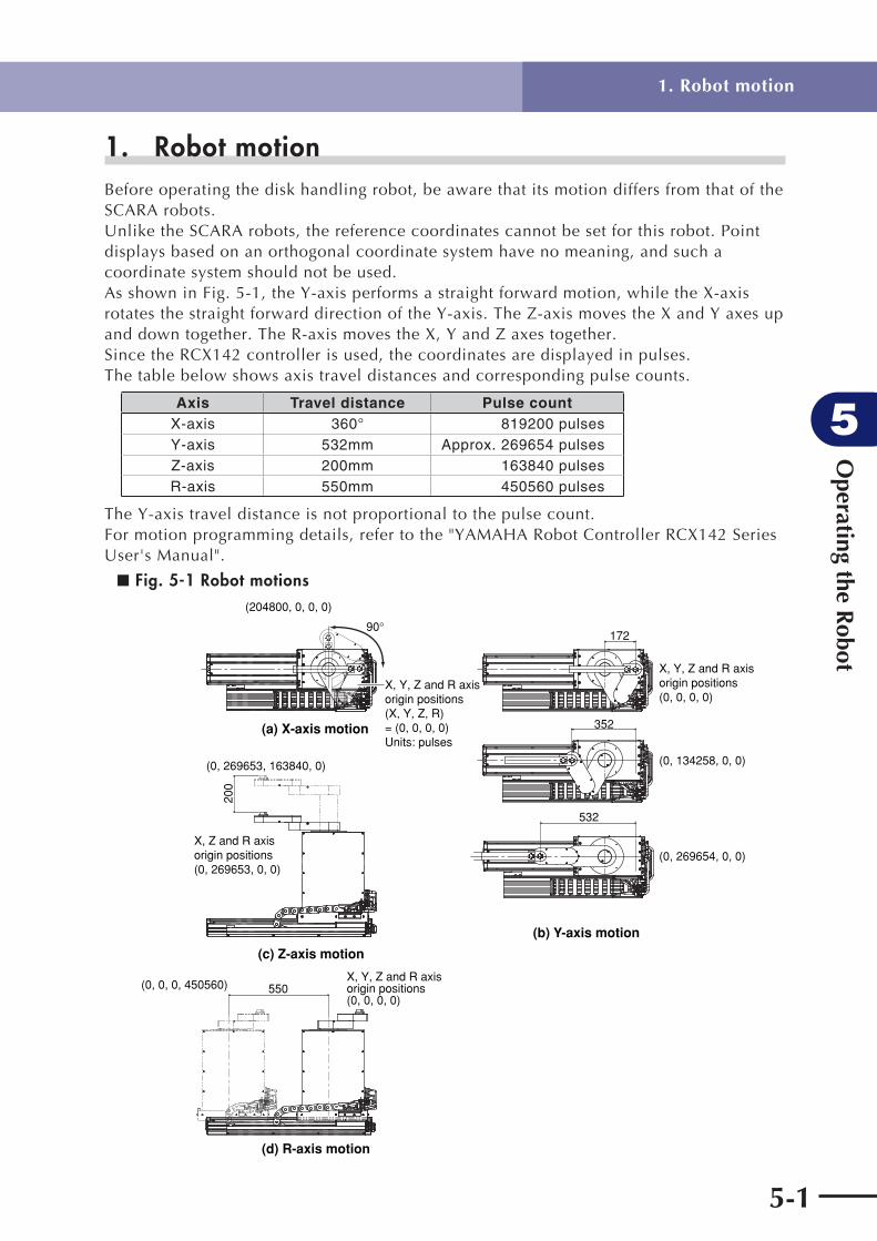
Operating the R
obot
5
5-1
1. Robot motion
1. Robot motion Before operating the disk handling robot, be aware that its motion differs from that of the SCARA robots. Unlike the SCARA robots, the reference coordinates cannot be set for this robot. Point displays based on an orthogonal coordinate system have no meaning, and such a coordinate system should not be used.As shown in Fig. 5-1, the Y-axis performs a straight forward motion, while the X-axis rotates the straight forward direction of the Y-axis. The Z-axis moves the X and Y axes up and down together. The R-axis moves the X, Y and Z axes together.Since the RCX142 controller is used, the coordinates are displayed in pulses. The table below shows axis travel distances and corresponding pulse counts.
Axis Travel distance Pulse countX-axis 360° 819200 pulsesY-axis 532mm Approx. 269654 pulsesZ-axis 200mm 163840 pulsesR-axis 550mm 450560 pulses
The Y-axis travel distance is not proportional to the pulse count.For motion programming details, refer to the "YAMAHA Robot Controller RCX142 Series User's Manual".
■ Fig. 5-1 Robot motions
X, Y, Z and R axis origin positions(X, Y, Z, R)= (0, 0, 0, 0) Units: pulses
(a) X-axis motion
(c) Z-axis motion
(d) R-axis motion
(b) Y-axis motion
X, Y, Z and R axis origin positions (0, 0, 0, 0)
(0, 134258, 0, 0)
(0, 269654, 0, 0)
352
172
532
200
(204800, 0, 0, 0)
(0, 269653, 163840, 0)
X, Z and R axis origin positions (0, 269653, 0, 0)
550(0, 0, 0, 450560)X, Y, Z and R axis origin positions (0, 0, 0, 0)
90

Operating the R
obot
5
5-2
2. Operating the robot
2. Operating the robotThe robot's X-axis and Y-axis acceleration is determined by the "X-axis motion only" or "Y-axis motion only" operations shown in Fig. 5-2 below. Therefore, when the X-axis and Y-axis are operated simultaneously or the X-axis rotates while the Y-axis is far from its origin position, this will shorten the drive system life, and could result in mechanical damage, overload conditions, and residual vibration during positioning.The Y-axis should always be near its origin position when the X-axis rotates, and the X and Y axes should not be operated simultaneously.The R-axis (travel axis) is located beneath the disk handling robot. Do not attempt to move the X, Y and Z axes while the travel axis is moving. If attempted, an inertia force will be applied to the X and Y axes by the travel axis motion. This will shorten the drive system life and could result in mechanical damage, overload conditions, and residual vibration during positioning. If the Z-axis is moved while the travel axis is moving, the Z-axis harness may interfere with the Z-axis drive section, causing the harness wires to break.
A sample robot motion program is shown below. (See also Fig. 5-3.)
* L0:FOR I=1 TO 10MOVE P, P[ I ]DELAY 1000NEXT IGOTO * L0

Operating the R
obot
5
5-3
2. Operating the robot
■ Fig. 5-2 Robot motions
Load (a) X-axis motion only
(b) Y-axis motion only
(c) X, Y and X axis operation prohibited during R-axis (travel axis) motion

Operating the R
obot
5
5-4
■ Fig. 5-3
P1 (204800, 0, 106496, 0)Units: pulses
P2 (204800, 269654, 106496, 0)
P3 (204800, 269654, 163840, 0)
P4 (204800, 0, 163840, 0)
P5 (204800, 0, 163840, 450560)
P9 (0, 0, 106496, 450560)
P10 (0, 0, 106496, 0)
P8 (0, 269654, 106496, 450560)
P7 (0, 269654, 163840, 450560)
P6 (0, 0, 163840, 450560)
RepeatStart
Z-axis moves up Z-axis moves down
2. Operating the robot

5-5
Operating the R
obot
5
3. Creating point data, direct teaching, and external forces to arms
3. Creating point data, direct teaching, and external forces to armsDirect X and Y axis teaching is difficult when the servo is OFF because any attempt to rotate the X-axis by hand will result in Y-axis motion (Y-axis performs a straight forward motion). Since the Z-axis is heavy, it is hazardous to perform direct teaching. X, Y and Z axis point data should therefore be created by a manual data-in or teaching playback operation. For details, refer to the "YAMAHA Robot Controller RCX142 Series User's Manual". Torque should never be applied to the Y-axis and tool attachment shaft by hand, as this could cause belt slippage in the X-axis and Y-axis arms, or could result in damage.

5-6
MEMO

Chapter 6 Periodic Inspection
Contents
1. Overview 6-1
2. Precautions 6-2
3. Daily inspection 6-3
4. Six-month inspection 6-5
5. Replacing the harmonic drive grease 6-7
5.1 Replacement interval 6-7

Periodic Inspection
6
6-1
1. Overview
1. Overview Daily and periodic inspection of the YAMAHA robot is essential in order to ensure safe and efficient operation. This chapter describes the periodic inspection items and procedures for the disk handling robots.
Periodic inspection includes:
• Daily inspection
• 6-month inspection
• Replacing the grease for speed reduction gear (harmonic drive)
Make sure that you thoroughly understand details of the inspection and follow the procedures and precautions explained in this chapter.
Periodic Inspection
6
6-2
2. Precautions
2. Precautions
(1) Periodic inspection must be performed by or in the presence of personnel who have received the Robot Training given by YAMAHA or YAMAHA dealers.
(2) Do not attempt any inspection, adjustment, repair and parts replacement not described in this manual. This work requires specialized technical knowledge and skill, and may also involve work hazards.
(3) When inspection is required inside the safety enclosure, always turn off the controller and also the external switch board.
(4) If the inspection or maintenance procedure calls for operation of the robot, stay outside the safety enclosure.
(5) Place a sign indicating the robot is being inspected, to keep others from operating the controller switch, programming unit or operation panel.
(6) Use only the lubricants specified by YAMAHA or YAMAHA dealers.
(7) To check the operation after inspection, see "6. Trial operation" in Chapter 1.
WARNING
• When you need to touch the terminals or connectors on the outside of the controller during inspection, always fi rst turn off the controller power and also the power source in order to prevent possible electrical shock. • Never touch any internal parts of the controller. • The controller must be installed outside the safety enclosure. • When inspecting the controller, it is dangerous to enter the safety enclosure while the controller power is ON.
For precautions on handling the controller, refer to the "YAMAHA Robot Controller RCX142 Series User's Manual".

Periodic Inspection
6
6-3
3. Daily inspection
3. Daily inspection The following inspections must be performed every day before and after operating the robot.
(1) Inspection to be performed with the controller turned off
1) Turn off the controller.
2) Place a sign indicating the robot is being inspected, to keep others from operating the controller switch.
3) Enter the safety enclosure and check the following points.
Checkpoint Procedure
Wire harness in cable carrierRobot cableUser cable and wiring
Check for scratches, dents and excessive bend and kinks. (If the wire harness in the cable carrier or robot cable is damaged, contact YAMAHA dealer.)
Air regulator, air coupler, air tube, solenoid valve, air cylinder
• Check air pressure.• Check for air leaks.• Check drain.• Check air filter for clogging or damage.
Robot exteriorCheck for damage. (If damage is found, contact YAMAHA dealer.)
(2) Inspection to be performed with the controller turned on
1) Check that no one is inside the safety enclosure, and then turn on the controller.
2) Place a sign indicating the robot is being inspected, to keep others from operating the controller, programming unit or operation panel.
3) Check the following points from outside the safety enclosure.
Checkpoint Procedure
Safety enclosure
Check if the safety enclosure is in place. Check if emergency stop is triggered when the door is opened. Check if warning labels are affixed at the entrance and clearly visible.
Emergency stop device Press the emergency stop button to check if it works.
Robot movementCheck for abnormal movement and excessive vibration and noise. (If an abnormal condition is found, contact YAMAHA dealer.)
Z-axis brake operation *1Check if the brake works to stop the Z-axis from dropping more than 3mm from the stationary point. (If an abnormal condition is found, contact YAMAHA dealer.)
*1: Visually check the Z-axis movement when you press the emergency stop button from outside the safety enclosure and also when you turn off the controller.

Periodic Inspection
6
6-4
(3) Adjustment and parts replacement
1) After inspection, if you notice any adjustment or parts replacement is needed, first turn off the controller and then enter the safety enclosure to perform the necessary work. After adjustment or replacement is finished, again review the checkpoints outlined in (1) and (2) above.
2) If repair or parts replacement is required for the robot or controller, please contact your YAMAHA dealer. This work requires specialized technical knowledge and skill, so do not attempt it by yourself.
3. Daily inspection
Periodic Inspection
6
6-5
4. Six-month inspection The following inspections must be performed every 6 months.
WARNING
• The Z-axis will slide down when the Z-axis brake is released, causing a hazardous situation. Do not release the brake when lubricating the Z-axis parts. • Injury can occur if hands or fi ngers are squeezed between the drive pulley and belt. Always turn off the controller and use caution when handling these parts.
! CAUTION
The ball screw and guide life may shorten if the grease recommended by YAMAHA is not used.
(1) Inspection to be performed with the controller turned off
1) Turn off the controller.
2) Place a sign showing that the robot is being inspected, to keep others from operating the controller switch.
3) Enter the safety enclosure and check the following points.
Checkpoint Procedure
Major bolts and screws on robot (only for bolts and screws exposed externally)
Check for looseness and tighten if necessary.*1
X, Y, Z and R axis timing belts Check belt tension. (See 6 in Chapter 4.)
Detection areas of X and Y axis origin sensors
Clean if it is dirty. (See 3.5 in Chapter 4.)
Controller
Check for looseness at each terminal and connector on the controller panel. (See 4 in Chapter 3 and also "YAMAHA Robot Controller RCX142 Series User's Manual.)
Grease on Z-axis ball screw and guide
After removing old grease with wiping cloth, apply LG2 (NSK) grease to the Z-axis ball screw shaft surface and guide rail. (See Fig. 6-1.)(To remove the cover, see "3.4 Removing the robot covers" in Chapter 4.
Z-axis ball screw and guideCheck for play or backlash. (If an abnormal condition is found, contact YAMAHA dealer.)
4. Six-month inspection

Periodic Inspection
6
6-6
■ Table 6-1 *1: Bolt tightening torque
Bolt size Tightening torque (kgf.cm) Tightening torque (N.m)
M3 button head bolt 14 1.4
M4 set screw 20 2.0
M3 20 2.0
M4 46 4.5
M5 92 9.0
M6 156 15.3
M8 380 37
M10 720 71
M12 1310 128
M14 2090 205
For 6-month inspection of the R-axis (travel axis), refer to the F17 single-axis robot described in the "FLIP-X Series User's Manual".
■ Fig. 6-1
Ball screw
Guide
(2) Adjustment and parts replacement
1) After inspection, if you notice any adjustment or parts replacement is needed, first turn off the controller and then enter the safety enclosure to perform the necessary work. After adjustment or replacement is finished, again review the checkpoints outlined in (1) above.
2) If repair or parts replacement is required for the robot or controller, please contact your YAMAHA dealer. This work requires specialized technical knowledge and skill, so do not attempt it by yourself.
4. Six-month inspection
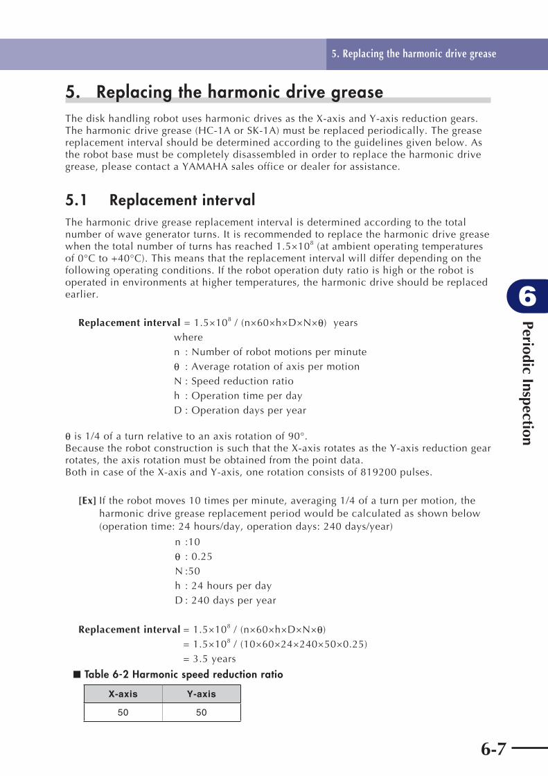
Periodic Inspection
6
6-7
5. Replacing the harmonic drive grease The disk handling robot uses harmonic drives as the X-axis and Y-axis reduction gears. The harmonic drive grease (HC-1A or SK-1A) must be replaced periodically. The grease replacement interval should be determined according to the guidelines given below. As the robot base must be completely disassembled in order to replace the harmonic drive grease, please contact a YAMAHA sales office or dealer for assistance.
5.1 Replacement interval The harmonic drive grease replacement interval is determined according to the total number of wave generator turns. It is recommended to replace the harmonic drive grease when the total number of turns has reached 1.5×10⁸ (at ambient operating temperatures of 0°C to +40°C). This means that the replacement interval will differ depending on the following operating conditions. If the robot operation duty ratio is high or the robot is operated in environments at higher temperatures, the harmonic drive should be replaced earlier.
Replacement interval = 1.5×10⁸ / (n×60×h×D×N×θ) years where n : Number of robot motions per minute θ : Average rotation of axis per motion N : Speed reduction ratio h : Operation time per day D : Operation days per year
θ is 1/4 of a turn relative to an axis rotation of 90°. Because the robot construction is such that the X-axis rotates as the Y-axis reduction gear rotates, the axis rotation must be obtained from the point data. Both in case of the X-axis and Y-axis, one rotation consists of 819200 pulses.
[Ex] If the robot moves 10 times per minute, averaging 1/4 of a turn per motion, the harmonic drive grease replacement period would be calculated as shown below (operation time: 24 hours/day, operation days: 240 days/year)
n :10 θ : 0.25 N :50 h : 24 hours per day D : 240 days per year
Replacement interval = 1.5×10⁸ / (n×60×h×D×N×θ) = 1.5×10⁸ / (10×60×24×240×50×0.25) = 3.5 years
■ Table 6-2 Harmonic speed reduction ratio
X-axis Y-axis
50 50
5. Replacing the harmonic drive grease
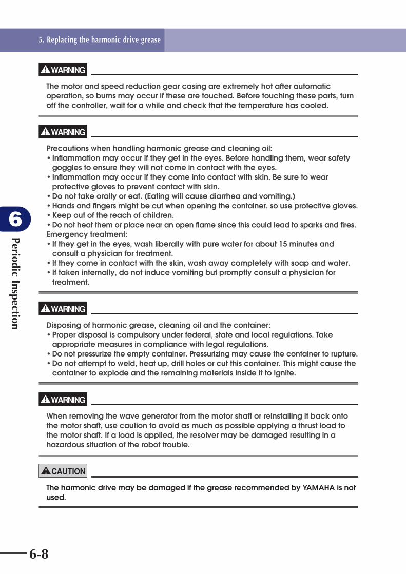
Periodic Inspection
6
6-8
WARNING
The motor and speed reduction gear casing are extremely hot after automatic operation, so burns may occur if these are touched. Before touching these parts, turn off the controller, wait for a while and check that the temperature has cooled.
WARNING
Precautions when handling harmonic grease and cleaning oil: • Infl ammation may occur if they get in the eyes. Before handling them, wear safety goggles to ensure they will not come in contact with the eyes. • Infl ammation may occur if they come into contact with skin. Be sure to wear protective gloves to prevent contact with skin. • Do not take orally or eat. (Eating will cause diarrhea and vomiting.) • Hands and fi ngers might be cut when opening the container, so use protective gloves. • Keep out of the reach of children. • Do not heat them or place near an open fl ame since this could lead to sparks and fi res. Emergency treatment: • If they get in the eyes, wash liberally with pure water for about 15 minutes and consult a physician for treatment. • If they come in contact with the skin, wash away completely with soap and water. • If taken internally, do not induce vomiting but promptly consult a physician for treatment.
WARNING
Disposing of harmonic grease, cleaning oil and the container: • Proper disposal is compulsory under federal, state and local regulations. Take appropriate measures in compliance with legal regulations. • Do not pressurize the empty container. Pressurizing may cause the container to rupture. • Do not attempt to weld, heat up, drill holes or cut this container. This might cause the container to explode and the remaining materials inside it to ignite.
WARNING
When removing the wave generator from the motor shaft or reinstalling it back onto the motor shaft, use caution to avoid as much as possible applying a thrust load to the motor shaft. If a load is applied, the resolver may be damaged resulting in a hazardous situation of the robot trouble.
! CAUTION
The harmonic drive may be damaged if the grease recommended by YAMAHA is not used.
5. Replacing the harmonic drive grease

Periodic Inspection
6
6-9
Recommended grease Use the following harmonic drive grease.
HC-1A or SK-1A (made by Harmonic Drive Systems Inc.)
(Do not use 4B No.2 grease as it may leak out.)
! CAUTION
Harmonic drive • Do not apply strong shocks or impacts to these parts such as with a hammer. Also, do not scratch, scar or dent these parts by dropping, etc. Such actions will damage the harmonic drive. • The specifi ed performance cannot be maintained if any part of the harmonic drive is used in a damaged state. This damage or wear may also lead to trouble with the harmonic drive.
! CAUTION
A positional shift occurs when the harmonic drive grease is replaced. Therefore, an absolute reset and point data resetting are required after replacing the grease.
5. Replacing the harmonic drive grease

6-10
MEMO

Chapter 7 Specifi cations
Contents
1. Basic specifications 7-1
2. External view and dimensions 7-3
3. Robot's internal wiring diagram 7-15
4. Robot's internal tubing 7-16
5. Wiring tables 7-17
6. Maintenance parts 7-28


Specifi cations
7
7-1
1. Basic specifications
1. Basic specifications
(1) 4-axis specifications
Payload 0.2kg (R-axis rotational moment of inertia 0.04kgfcms2)
Working envelope
Y-axis forward stroke 532mm
X-axis rotation angle 340°
Z-axis up/down stroke 200mm
R-axis travel stroke 550mm
Motor
X-axis 200w
Y-axis 100w
Z-axis 400w
R-axis 400w
Maximum speed
Y-axis forward direction 300mm/s
X-axis rotation 290°/s
Z-axis up/down direction 1000mm/s
R-axis travel direction 1000mm/s
Resolution
Y-axis forward direction 50µm
X-axis rotation direction 0.0010°
Z-axis up/down direction 20µm
R-axis travel direction 20µm
Repeatability *
X and Y axes: tool attachment shaft position
±0.1mm
Z and R axes: tool attachment shaft position
±0.05mm
Cleanliness degreeClass 1000 (0.3µm base during suction. Tool attachment shaft, Z-axis up/down stroke range, and R-axis travel area do not conform to clean room specs.)
Suction rate 60Nl/min
User tubing φ4, 2 tubes
User wiring 0.1mm2, 4 wires
WeightRobot body: 70kg
RCX142 controller: W180×D235×H250mm, 6.5kg
Travel limit1. Soft limit (X, Y, Z and R axes)2. Mechanical limit (X, Y, Z and R axes)
Robot cable 3.5m, option: 1m, 2m, and 4m to 10m (in 1m steps)
Arm and base Almite coated aluminum
Arm and base covers Almite coated aluminum
Outer bolts and screws Stainless
* At constant ambient temperature

Specifi cations
7
7-2
1. Basic specifications
(2) 3-axis specifications
Payload 0.2kg (R-axis rotational moment of inertia 0.04kgfcms2)
Working envelope
Y-axis forward stroke 532mm
X-axis rotation angle 340°
Z-axis up/down stroke 200mm
Motor
X-axis 200w
Y-axis 100w
Z-axis 400w
Maximum speed
Y-axis forward direction 300mm/s
X-axis rotation 290°/s
Z-axis up/down direction 1000mm/s
Resolution
Y-axis forward direction 50µm
X-axis rotation direction 0.0010°
Z-axis up/down direction 20µm
Repeatability *
X and Y axes: R-axis position at arm end
±0.1mm
Z axis: R-axis position at arm end
±0.05mm
Cleanliness degreeClass 1000 (0.3µm base during suction, R-axis position at arm end in Z-axis up/down stroke range)
Suction rate 60Nl/min
User tubing φ4, 2 tubes
User wiring 0.1mm2, 4 wires
WeightRobot body: 40kg
RCX142 controller: W180×D235×H250mm, 6.5kg
Travel limit1. Soft limit (X, Y and Z axes)2. Mechanical limit (X, Y and Z axes)
Robot cable 3.5m, option: 5m, 10m
Arm and base Almite coated aluminum
Arm and base covers Almite coated aluminum
Outer bolts and screws Stainless
* At constant ambient temperature
Sound level
Maximum sound pressure level of robot(at 10dB or more difference from
background sound pressure level )Position of maximum sound pressure level
77.0dB
In direction of 45° to right, as viewed from front of robot1.0m away from arm's movable section 1.4m height
! CAUTION
Sound level may increase when sound refl ecting objects are located near the robot.

Specifi cations
7
7-3
2. External view and dimensions
2. External view and dimensions
■ Fig. 7-1 4-axis specifications (without hand holder) (1)
170
R360
340° 2°
2°
R180
Tool attachment shaft
Working envelope
Working envelope (tool attachment shaft position) and X-axis mechanical stopper position
Mechanical stopper position may vary somewhat depending on parts machining accuracy.X and Y axis arms and tool attachment shaft may not extend fully, depending on parts machining accuracy or assembly condition.
X-axis mechanical stopper position

Specifi cations
7
7-4
2. External view and dimensions
■ Fig. 7-1 4-axis specifications (without hand holder) (2)
5(Note 4)5 (Note 4)
3(No
te 4
)
97.5
147 199
240 2550 (R-axis stroke) 5060
576 63
066
7
585 68
888
8
200
(Z-a
xis
stro
ke)
Tool attachment shaft
75 40915
35767
132
2004X200=800
180180
3(N
ote
4)
214
217
123.
7
11894
A
X-axis
Z-axisY-axis
10- 9 thru-hole (thickness: 27)
20050
5.6
5.6
1313
6.5
6.5
11.3 11.3
3.3 3.3
Details of AScale 1:1
User wiring (0.1mm2)Red : User wiring 1White : User wiring 2Yellow : User wiring 3Blue : User wiring 4
User tubing 1
BB
9.31
Cross section B-BScale 2:1
O-ring S7 (2 pcs supplied)
6-M3×0.5, depth: 10
User tubing 2
User wiring connector (10 pins) Red : User wiring 1 White : User wiring 2 Green : User wiring 3 White : User wiring 4
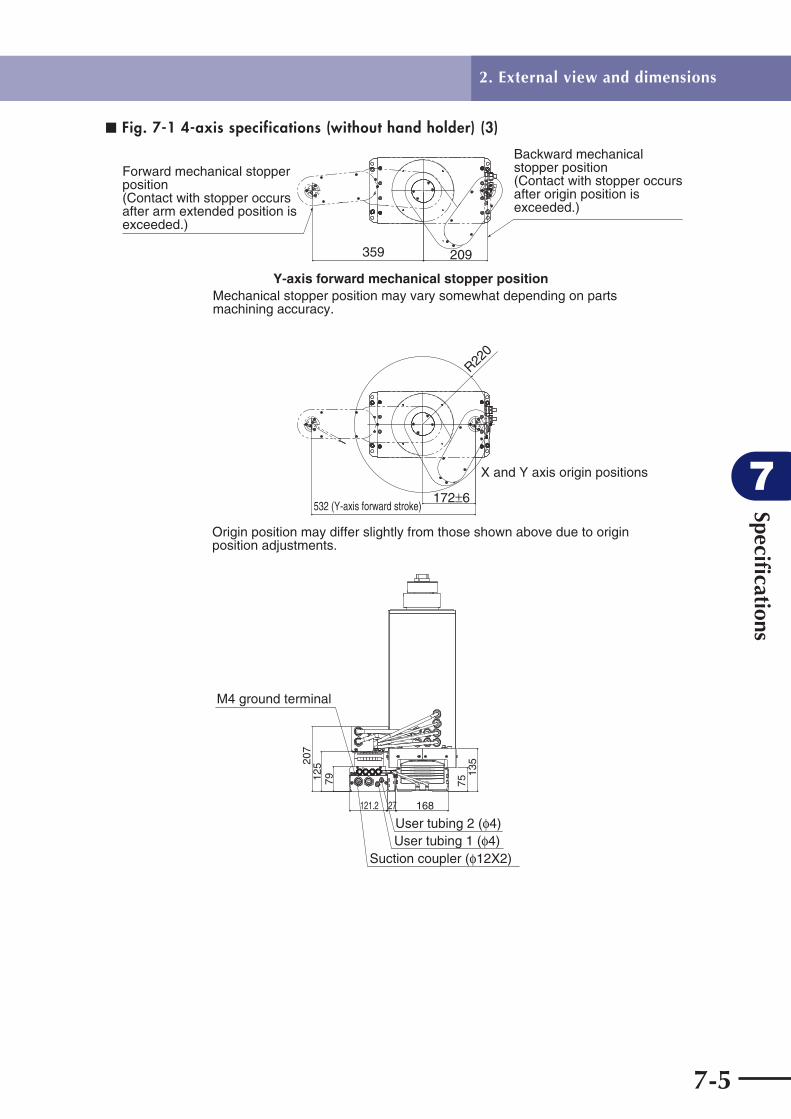
Specifi cations
7
7-5
2. External view and dimensions
■ Fig. 7-1 4-axis specifications (without hand holder) (3)
R220
532 (Y-axis forward stroke)172 6
X and Y axis origin positions
Origin position may differ slightly from those shown above due to origin position adjustments.
359 209
Y-axis forward mechanical stopper positionMechanical stopper position may vary somewhat depending on parts machining accuracy.
Forward mechanical stopper position(Contact with stopper occurs after arm extended position is exceeded.)
Backward mechanical stopper position(Contact with stopper occurs after origin position is exceeded.)
16827121.2
7912520
7
7513
5
User tubing 2 ( 4)User tubing 1 ( 4)
Suction coupler ( 12X2)
M4 ground terminal

Specifi cations
7
7-6
2. External view and dimensions
■ Fig. 7-2 4-axis specifications (with hand holder) (1)
R360
340°
2°
2°
R180
Working envelope (tool attachment shaft position) and X-axis mechanical stopper position
Mechanical stopper position may vary somewhat depending on parts machining accuracy.X and Y axis arms and tool attachment shaft may not extend fully, depending on parts machining accuracy or assembly condition.
170
40+
0.2
+0.
1
60
55.529 0
-0.1
69
R30
6.5
6.5
1313
11.3 11.3
40 0 -0
.1
40 0-0.1
Hand support
2
Tool attachment shaft
Working envelope
X-axis mechanical stopper position
Cross section D-DScale 1:1
6-M3×0.5 thru-hole

Specifi cations
7
7-7
2. External view and dimensions
■ Fig. 7-2 4-axis specifications (with hand holder) (2)
5 (Note 4)5 (Note 4)
3 (N
ote
4)3
(Not
e 4)
200
(Z-a
xis
stro
ke)
887
97.5
5060
576 63
0 667
585
199147
240±2550 (R-axis stroke)
687
673
(Hei
ght t
o ha
nd to
p su
rface
wh
en Z
-axis
is fu
lly lo
were
d)
Tool attachment shaft
75 40915
35767
132
2004X200=800
180180
214
217
123.
7
11894
A
X-axis
Z-axisY-axis
D D
B B
User wiring connector (10 pins) Red : User wiring 1White : User wiring 2Green : User wiring 3White : User wiring 4
5
Use
r han
d th
ickn
ess
mus
t no
t exc
eed
3mm
Cross section B-BScale 1:1
Hand 6 M3 bolts, length: 8Hand holder cover
Hand support
7.3
1
Details of CScale 4:1
O-ring S5 (supplied)
136.
56.
513
11.3 11.349 Details of A
Scale 1:1
User tubing 1
User tubing 2 ( 4)
Inside of hand holder with cover removed
6- 3.5 thru-hole
Set screw (3 pcs) for hand holder tilt adjustment
Set screw lock nut
Hand holder mounting bolt (3 pcs)
C
10- 9 thru-hole (thickness: 27)
User wiring (0.1mm2)Red : User wiring 1White : User wiring 2Yellow : User wiring 3Blue : User wiring 4

Specifi cations
7
7-8
2. External view and dimensions
■ Fig. 7-2 4-axis specifications (with hand holder) (3)
R220
172±6532 (Y-axis forward stroke)
X and Y axis origin positions
Origin position may differ slightly from those shown above due to origin position adjustments.
359 209
Y-axis forward mechanical stopper positionMechanical stopper position may vary somewhat depending on parts machining accuracy.
Forward mechanical stopper position(Contact with stopper occurs after arm extended position is exceeded.)
Backward mechanical stopper position(Contact with stopper occurs after origin position is exceeded.)
16827121.2
7912520
7
7513
5
User tubing 2( 4)User tubing 1( 4)
Suction coupler ( 12X2)
M4 ground terminal

Specifi cations
7
7-9
2. External view and dimensions
■ Fig. 7-3 3-axis specifications (without hand holder) (1)
R360
340°
2°
2°
R180
Tool attachment shaft
Working envelope
Working envelope (tool attachment shaft position) and X-axis mechanical stopper position
Mechanical stopper position may vary somewhat depending on parts machining accuracy.X and Y axis arms and tool attachment shaft may not extend fully, depending on parts machining accuracy or assembly condition.
X-axis mechanical stopper position

Specifi cations
7
7-10
2. External view and dimensions
■ Fig. 7-3 3-axis specifications (without hand holder) (2)
33
147172
389
199217
46551
1568
547
200
(Z-a
xis
stro
ke)
768
1545
6
Z-axis origin position
Tool attachment shaft
Y-axisX-axis
Z-axis
Z-axis lower-end mechanical stopper positionZ-axis lowers to this position during absolute reset (return to origin).
180 180
94
118
164 209389
6969
8787
214
50
4-M8×0.75Leveling bolt
BB
A
4- 10 for M8 mounting bolt
20050
5.6
5.6
1313
6.5
6.5
11.3 11.3
3.3 3.3
Details of AScale 1:1
User wiring (0.1mm2)Red : User wiring 1White : User wiring 2Yellow : User wiring 3Blue : User wiring 4
User tubing 1
User tubing 2
9.3
1
Cross section B-BScale 2:1
O-ring S7 (2 pcs supplied)
Z-axis upper-end mechanical stopper position

Specifi cations
7
7-11
2. External view and dimensions
■ Fig. 7-3 3-axis specifications (without hand holder) (3)
R220
532 (Y-axis forward stroke) 172±6
X and Y axis origin positionsOrigin position may differ slightly from those shown above due to origin position adjustments.
359 209
Y-axis forward mechanical stopper positionMechanical stopper position may vary somewhat depending on parts machining accuracy.
Forward mechanical stopper position(Contact with stopper occurs after arm extended position is exceeded.)
Backward mechanical stopper position(Contact with stopper occurs after origin position is exceeded.)
1540
4020
3535
16 30
3530
30
M4 ground terminal
User wiring connector (4 pins)
Suction tube ( 12) in base
Suction tube ( 12) in X and Y axis arms
User tubing 1 ( 4)User tubing 2 ( 4)
Robot cable

Specifi cations
7
7-12
2. External view and dimensions
■ Fig. 7-4 3-axis specifications (with hand holder) (1)
R360
340°
2°
2°
R 180
Tool attachment shaft
Working envelope
Working envelope (tool attachment shaft position) and X-axis mechanical stopper position
Mechanical stopper position may vary somewhat depending on parts machining accuracy.X and Y axis arms and tool attachment shaft may not extend fully, depending on parts machining accuracy or assembly condition.
X-axis mechanical stopper position
Cross section B-BScale 1:1
6955.5
29 0-0.1
60 40+
0.2
+0.
1
R30
40 0 -0
.140 0
-0.1
11.3 11.3
6.5
1313
6.5
6-M3×0.5 thru-hole
2
Hand support
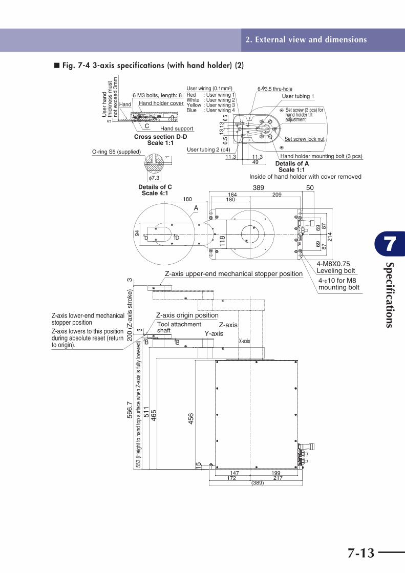
Specifi cations
7
7-13
2. External view and dimensions
■ Fig. 7-4 3-axis specifications (with hand holder) (2)
3
3
147172
(389)
199217
465511
1545
6
200
(Z-a
xis
stro
ke)
566.
755
3 (H
eigh
t to
hand
top
surfa
ce w
hen
Z-ax
is is
fully
lowe
red)
Z-axis origin positionTool attachment shaft Y-axis
X-axis
Z-axisZ-axis lower-end mechanical stopper positionZ-axis lowers to this position during absolute reset (return to origin).
Z-axis upper-end mechanical stopper position
180 180
94
118
164 209389
6969
8787
214
50
4-M8X0.75Leveling bolt
4- 10 for M8 mounting bolt
B B
D D
A
13
4911.3 11.3
136.
56.
5
Details of AScale 1:1
User tubing 1
User tubing 2 ( 4)Hand holder mounting bolt (3 pcs)
Set screw (3 pcs) for hand holder tilt adjustment
Set screw lock nut
Inside of hand holder with cover removed
Use
r ha
nd
thic
knes
s m
ust
not e
xcee
d 3m
m5
Cross section D-DScale 1:1
Hand Hand holder cover
Hand support
6 M3 bolts, length: 8
7.3
1
Details of CScale 4:1
O-ring S5 (supplied)
C
User wiring (0.1mm2)Red : User wiring 1White : User wiring 2Yellow : User wiring 3Blue : User wiring 4
6- 3.5 thru-hole
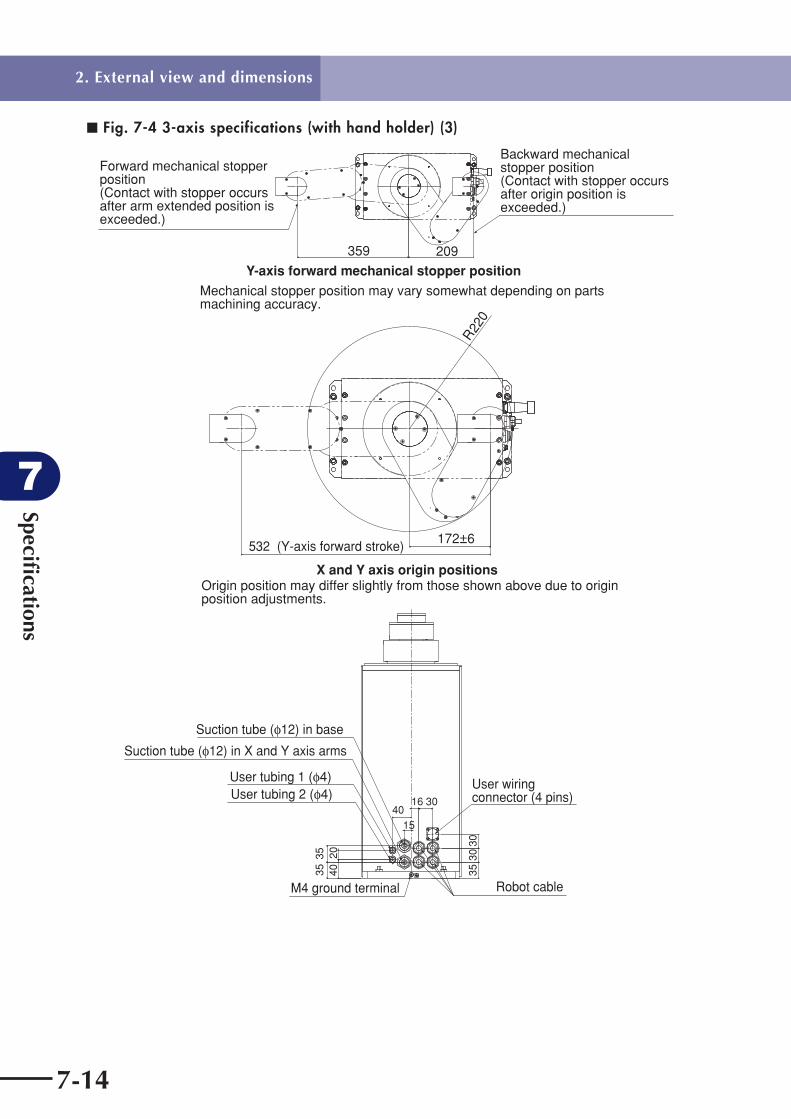
Specifi cations
7
7-14
2. External view and dimensions
■ Fig. 7-4 3-axis specifications (with hand holder) (3)
R22
0
172±6532 (Y-axis forward stroke)
X and Y axis origin positionsOrigin position may differ slightly from those shown above due to origin position adjustments.
359 209
Y-axis forward mechanical stopper position
Mechanical stopper position may vary somewhat depending on parts machining accuracy.
Forward mechanical stopper position(Contact with stopper occurs after arm extended position is exceeded.)
Backward mechanical stopper position(Contact with stopper occurs after origin position is exceeded.)
1540
4020
3535
16 30
3530
30
M4 ground terminal
User wiring connector (4 pins)
Suction tube ( 12) in base
Suction tube ( 12) in X and Y axis arms
User tubing 1 ( 4)User tubing 2 ( 4)
Robot cable

Specifi cations
7
7-15
3. Robot's internal wiring diagram
3. Robot's internal wiring diagram
(1) 4-axis specifications
See "5. Wiring tables" for items numbered q to !8.
■ Fig. 7-5
User wiring
X-axisZ-axis
X-axisZ-axis
To controller
ConnectorUser wiring connector
Y-axis sensor
Y-axis motor
X-axis motor
Z-axis motor
X-axis sensor
Robot cable
R-axis motor
Tool attachment shaft Y-axis arm
X-axis arm
Base
Wiring boxR-axis
(2) 3-axis specifications
The 3-axis model has no R-axis. Robot cable and user wiring connector directly come out of the base.
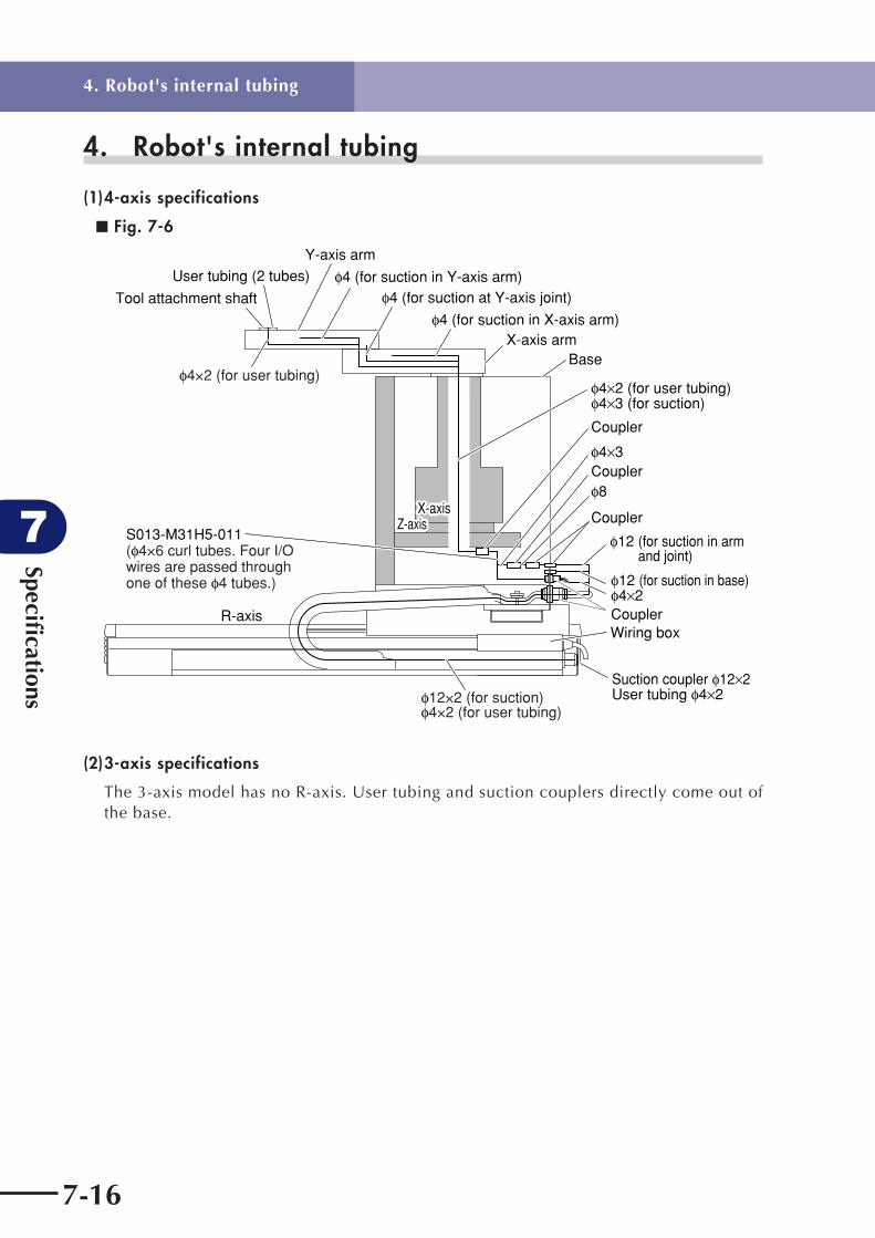
Specifi cations
7
7-16
4. Robot's internal tubing
(1) 4-axis specifications
■ Fig. 7-6
Tool attachment shaft
User tubing (2 tubes)
User tubing 4 2
Y-axis arm
4 (for suction in Y-axis arm)4 (for suction at Y-axis joint)
4 (for suction in X-axis arm)
BaseX-axis arm
Coupler
Coupler
Coupler
Coupler
12 (for suction in base)
4 3 (for suction)
4 3
4 2
8
4 2 (for user tubing)
Wiring box
Suction coupler 12 2
12 (for suction in arm and joint)
X-axisZ-axis
X-axisZ-axis
R-axis
4×2 (for user tubing)
S013-M31H5-011( 4×6 curl tubes. Four I/O wires are passed through one of these 4 tubes.)
12×2 (for suction)4×2 (for user tubing)
(2) 3-axis specifications
The 3-axis model has no R-axis. User tubing and suction couplers directly come out of the base.
4. Robot's internal tubing

Specifi cations
7
7-17
5. Wiring tables(1) 4-axis specifications4-axis specifications q-1
Signal ConnectionConnector No. WireColor/No.ConnectorNo.
S00R-M3643-X02 (Robot cableX=1 (Length: 1.0m) , X=2 (2.0m), X=3 (3.5m), X=4 (4.0m) , X=5 (5.0m) , X=6 (6.0m), X=7 (7.0m) , X=8 (8.0m) , X=9 ( (9.0m) , X=A (10.0m) )
Wiring box side Controller side
Resolver
Brake
Resolver
Brake
Sensor
Sensor
S2
S4
S1
S3
R1
R2
DG
MB+
MB-
S2
S4
S1
S3
R1
R2
DG
MB+
MB-
HLIM
GND24
HLIM
GND24
24V
ORG
GND24
24V
ORG
GND24
U
V
W
FG
U
V
W
FG
XP
XBK
YBK
ORG
ORG
XM
Ring terminal
YM
Ring terminal
YP
XY
Blue
Orange
Green
Brown
Gray
Red
Black
Yellow
Pink
Violet
White
Blue/red
Orange/white
Green/white
Brown/white
Gray/white
Green
Green
Red/white
Yellow/black
Pink/black
White/blue
Blue/red
Orange/white
1
2
3
Yellow/green
4
5
6
0.3sqTwisted pair
0.3sqTwisted pair
0.3sqTwisted pair
Drain wire
0.3sqTwisted pair
0.3sqTwisted pair
0.3sqTwisted pair
0.3sqTwisted pair
Shield
0.3sqTwisted pair
0.3sq Twisted
0.3sqTwisted pair
0.3sq Twisted
0.3sqTwisted pair
0.75sq
0.75sq
0.75sq
0.75sq
0.75sq
0.75sq
0.75sq
XM
YM
Grounded in wiring box M4 ground terminal on the rear of wiring box
1
2
3
4
5
6
7
1
2
1
2
3
4
5
6
7
1
2
1
2
3
1
2
3
1
2
3
4
1
2
3
4
1
2
3
4
5
6
7
14
16
19
20
21
22
23
24
25
32
34
10
11
28
29
9
12
13
27
30
31
2
3
4
1
2
3
4
5. Wiring tables

Specifi cations
7
7-18
4-axis specifications q-2
Grounded in wiring box M4 ground terminal on the rear of wiring box
Resolver
Brake
Resolver
Brake
Sensor
Sensor
S2
S4
S1
S3
R1
R2
DG
MB+
MB-
S2
S4
S1
S3
R1
R2
DG
MB+
MB-
HLIM
GND24
HLIM
GND24
24V
ORG
GND24
24V
ORG
GND24
U
V
W
FG
U
V
W
FG
ZP
1
2
3
4
5
6
7
1
2
1
2
3
4
5
6
7
1
2
1
2
3
1
2
3
1
2
3
4
1
2
3
4
1
2
3
4
5
6
7
14
16
19
20
21
22
23
24
25
32
34
10
11
28
29
9
12
13
27
30
31
2
3
4
1
2
3
4
ORG
ORG
ZM
Ring terminal
RM
Ring terminal
RP
ZBK
RBK
ZR
ZM
RM
Blue
Orange
Green
Brown
Gray
Red
Green
Black
Yellow
Pink
Violet
White
Blue/red
Orange/white
Green/white
Green
Brown/white
Gray/white
Green
Green
Red/white
Yellow/black
Pink/black
White/blue
Blue/red
Orange/white
1
2
3
Yellow/green
4
5
6
0.3sqTwisted pair
0.3sqTwisted pair
0.3sqTwisted pair
Drain wire
0.3sqTwisted pair
0.3sqTwisted pair
0.3sqTwisted pair
0.3sqTwisted pair
Shield
0.3sqTwisted pair
0.3sq Twisted
0.3sqTwisted pair
0.3sq Twisted
0.3sqTwisted pair
0.75sq
0.75sq
0.75sq
0.75sq
0.75sq
0.75sq
0.75sq
Signal ConnectionConnector No. WireColor/No.ConnectorNo.
5. Wiring tables

Specifi cations
7
7-19
4-axis specifications w
KT8-M4814-N12 (Cable-carrier X and Y axis power wires, R-axis stroke 550mm)
Base side Wiring box sideConnector ConnectorSignal No. No.Connection RemarksMotor
Motor
UVW
F. G.UVW
F. G.
M1
M2Green/yellow
Green/yellow
0.75sq
0.75sq0.75sq
0.75sq
12341234
M1
M2
12341234
4-axis specifications e
Motor
KT8-M4813-N12 (Cable-carrier Z-axis power wire, R-axis stroke 550mm)
UVW
F. G.
M RedWhiteBlackYellow/green
M1234
1234
Base side Wiring box sideConnector ConnectorSignal No. No.Connection Remarks
4-axis specifications r
KT8-M4811-N13 (Cable-carrier Z-axis resolver and brake wires, R-axis stroke 550mm)
Encoder
Brake
S2S4S1S3R1R2
D, G24V
GND
P
BK
123456
712
123456
712
RedWhiteGreenWhiteYellowWhite
BlueWhite
P
BK
0.3sqTwisted pair
Drain wire0.3sqTwisted pair
Base side Wiring box sideConnector ConnectorSignal No. No.Connection Remarks
4-axis specifications t
Base side Wiring box sideConnector ConnectorSignal No. No.Connection Remarks
KT8-M4815-N04 (Cable-carrier I/O wire, R-axis stroke 550mm)
Only No.1 to No.4 are usable.
General-purpose I/O
I/O
12345678910
RedWhiteGreenWhiteYellowWhiteBlueWhiteVioletWhite
0.3sqTwisted pair
12345678910
I/O
5. Wiring tables

Specifi cations
7
7-20
4-axis specifications y
Encoder
Brake
Origin sensor
S2S4S1S3R1R2
D, G
BK+BK-
24VORG
P
BK
ORG
RedWhiteGreenWhiteYellowWhite
BlueWhite
VioletBlueBrown
0.3sqTwisted pair
Drain wire
0.3sqTwisted pair
0.3sq Twisted0.3sqTwisted pair
1234567
12
123
1234567
12
123
P
BK
ORG
KT8-M4816-N04: 2 pieces (Cable-carrier X and Y axis resolver and sensor wires, R-axis stroke 550mm)
24VGND
Base side Wiring box sideConnector ConnectorSignal No. No.Connection Remarks
4-axis specifications u
Signal Remarks
90K92-840240 (R-axis motor)
R-axis side Wiring box side
S2S4S1S3R1R2
SHIELD
UVWPE
YellowBlueRedBlackWhiteGreenBlack (Heat shrinkable tube)
RedWhiteBlackYellow/green
Color
Ring terminal
CN
CN1
CN2
S2S4S1S3R1R2SHIELD
UVWPE
Connection CN
1234567
1234
Grounded in wiring boxGrounded to R-axis frame and R-axis motor
5. Wiring tables

Specifi cations
7
7-21
4-axis specifications i
S013-M31H6-012 (X and Y axis curl cable, Z-axis stroke 200mm)
Ring terminal is grounded to Z-axis. Ring terminal is grounded to base.Only "Unit 1a" insulator coating is 0.3mm thick. Others are 0.15mm thick.
Base sideZ-axis side Connector Connector ColorSignal No. No.Connection WireX resolver
Y resolver
Origin sensor
Origin sensor
X motor
Y motor
S2S4S1S3R1R2DGS2S4S1S3R1R2DG
GNDORG24V24V
ORGGND
UVW
UVW
XP
YP
XORG
YORG
XM
YM
RedWhiteYellowBlueGrayBlackGreenRedWhiteYellowBlueGrayBlackGreenRedWhiteYellowBlueGrayBlackGreenRedWhiteYellow
Yellow/greenBlueGrayBlack
Yellow/green
0.2mm2
Twisted pair0.2mm2
Twisted pair0.2mm2
Twisted pairShield0.2mm2
Twisted pair0.2mm2
Twisted pair0.2mm2
Twisted pairShield
0.2mm2
Twisted pair
Shield
0.2mm2
0.75mm2
0.2mm2
0.75mm2
XP
YP
XORG
YORG
Ring terminal
XM
Ring terminal
YM
Ring terminal
12345671234567321123
123
123
12345671234567321123
1234
1234
Uni
t 1b
Uni
t 1c
Uni
t 1d
Uni
t 1a
Uni
t 1a
4-axis specifications o
S013-M31K9-002 (Z-axis motor)
Base side
Ring terminal is grounded to base.
Signal Color Connection CN RemarksNo.
1
S2S4S1S3R1R2
SHIELD
UVW
PE
BKBK
YellowBlueRedBlackWhiteGreenBlack (Heat shrinkable tube)
RedWhiteBlack
Yellow/green
YellowYellow
1234567
1234
12
CN1
CN2
Ring terminalRing terminal
CN3
S2S4S1S3R1R2SHIELD
UVW
PEPE
BKBK
5. Wiring tables

Specifi cations
7
7-22
4-axis specifications !0
...
10
S013-M31H5-011 (I/O curl cable + 5X 4 air tube, Z-axis stroke: 200mm)
0.1mm2
RedWhiteYellowBlue
1234
IOIO1234
User signal wireBase sideZ-axis side Connector Connector ColorSignal No. No.Connection Wire
4-axis specifications !1
S013-M31E0-001 (FG curl cable, Z-axis stroke: 200mm)
Ring terminal Yellow/green 0.75mm2Ring terminal
Ring terminal is grounded to Z-axis. Ring terminal is grounded to base.
Base sideZ-axis side Connector Connector ColorSignal No. No.Connection Wire
4-axis specifications !2
S013-M3146-003 (X-axis curl cable)
Ring terminal is grounded to X-axis.
Y resolver
Y motor
Origin sensor
S2S4S1S3R1R2DG
UVW
24VORGGND
XP
YM
YORG
Ring terminal
RedWhiteYellowBlueGrayBlackGreenRedWhiteYellowBlueGrayBlackYellow/green
0.2mm2
Twisted pair0.2mm2
Twisted pair0.2mm2
Twisted pairShield
0.2mm2
Coating t0.3
0.2mm2
Coating t0.150.2mm2 Coating t0.3
YP
YM
YORG
Ring terminal
1234567123123
1234567123123
Uni
t 1b
Uni
t 1a
Ring terminal is grounded to Z-axis.
Z-axis sideX-axis side Connector Connector ColorSignal No. No.Connection Wire
4-axis specifications !3
+24ORGGND
SignalBrownBlackBlue
123
Color Connection CN Z-axis side
KN3-M4850-301 (X-axis sensor)
123
No.
5. Wiring tables

Specifi cations
7
7-23
4-axis specifications !4
90K90-62012X (X-axis motor)
S2S4S1S3R1R2
SHIELD
UVW
PE
YellowBlueRedBlackWhiteGreenBlack (Heat shrinkable tube)
RedWhiteBlack
Yellow/green
CN1
CN2
Ring terminal
S2S4S1S3R1R2SHIELD
UVW
PE
1234567
123
Ring terminal is grounded to Z-axis.
Z-axis sideSignal Color Connection CN Remarks
4-axis specifications !5
S013-M31H4-001 (Arm I/O wire)
Z-axis side
0.1mm2
RedWhiteYellowBlue
1234
IO1234
User signal wireConnector Connector ColorSignal No. No.Connection WireTool
attachment shaft
4-axis specifications !7
+24ORGGND
SignalBrownBlackBlue
123
Color Connection CN X-axis side
KN3-M4850-501 (Y-axis sensor)
123
No.
5. Wiring tables

Specifi cations
7
7-24
4-axis specifications !8
S013-M31K0-011 (Y-axis motor)
S2S4S1S3R1R2
SHIELD
UVW
PE
YellowBlue/blackBrownBrown/blackRedBlackBlack (Heat shrinkable tube)
RedWhiteBlack
Yellow/green
CN1
CN2
Ring terminal
S2S4S1S3R1R2SHIELD
UVW
PE
1234567
123
X-axis sideSignal Color Connection CN Remarks
Ring terminal is grounded to X-axis.
5. Wiring tables

Specifi cations
7
7-25
(2) 3-axis specifications
Cables different from 4-axis specifications are shown below.3-axis specifications q-1
S00K-M8714-X02 (Robot cableX=1 (Length: 3.5m), X=2 (5.0m), X=3 (10m))
Resolver
Brake
Resolver
Origin sensor
S2
S4
S1
S3
R1
R2
DG
MB+
MB-
S2
S4
S1
S3
R1
R2
DG
FG
HLIM
GND24
HLIM
GND24
24V
ORG
GND
U
W
V
FG
U
W
V
ZP
ZBK
FG
RORG
ZM
Ring terminal
RM
RP
ZR
Blue
Orange
Green
Brown
Gray
Red
Green
Black
Yellow
Pink
Violet
White
Blue/red
Orange/white
Green/white
Brown/white
Gray/white
Green
Red/white
Black/white
Green
Green
White/blue
Blue/red2
Orange/white2
1
2
3
4
5
6
7
0.15sqTwisted pair
0.15sqTwisted pair
0.15sqTwisted pair
0.3sq
0.15sqTwisted pair
0.15sqTwisted pair
0.15sqTwisted pair
0.15sqTwisted pair
0.15sqTwisted pair
0.3sq
0.15sq
0.15sq
0.3sq
0.3sq
0.15sq
0.15sqTwisted pair
0.75sq
0.75sq
0.75sq
0.75sq
0.75sq
0.75sq
0.75sq
ZM
RM
1
2
3
4
5
6
7
1
2
1
2
3
4
5
6
7
1
1
2
3
1
2
3
1
2
3
1
2
3
4
5
6
7
14
16
15
17
19
20
21
22
23
24
25
18
36
10
11
28
29
27
30
31
2
3
4
1
2
3
4
Signal ConnectionConnector No. WireColor/No.ConnectorNo.Base side Controller side
5. Wiring tables

Specifi cations
7
7-26
3-axis specifications q-2
Resolver
Resolver
Origin sensor
Origin sensor
S2
S4
S1
S3
R1
R2
DG
S2
S4
S1
S3
R1
R2
DG
FG
HLIM
GND24
HLIM
GND24
GND
ORG
24V
24V
ORG
GND
U
W
V
FG
U
W
V
XP
YP
XORG
YORG
XM
Ring terminal
YM
FG
XY
Blue
Orange
Green
Brown
Gray
Red
Green
Black
Yellow
Pink
Violet
White
Blue/red
Green
Orange/white
Green/white
Green
Green
Yellow/black
Pink/black
Violet/white
White/blue
Blue/red2
Orange/white2
1 Black
2 White
3 Red
4 Green
5 Yellow
6 Brown
7 Blue
0.15sqTwisted pair
0.15sqTwisted pair
0.15sqTwisted pair
0.3sq
0.15sqTwisted pair
0.15sqTwisted pair
0.15sqTwisted pair
0.3sq
0.15sq
0.15sq
0.3sq
0.3sq
0.15sqTwisted pair
0.15sqTwisted pair
0.15sqTwisted pair
0.75sq
0.75sq
0.75sq
0.75sq
0.75sq
0.75sq
0.75sq
XM
YM
1
2
3
4
5
6
7
1
2
3
4
5
6
7
1
3
2
1
1
2
3
1
2
3
1
2
3
1
2
3
4
5
6
7
19
20
21
22
23
24
25
18
36
10
11
28
29
13
12
9
27
30
31
2
3
4
1
2
3
4
Signal ConnectionConnector No. WireColor/No.ConnectorNo.
Ring terminal is grounded to base.
5. Wiring tables

Specifi cations
7
7-27
3-axis specifications w
90K93-64214Z (Z-axis motor)
Base side
1
S2S4S1S3R1R2
SHIELD
UVW
PE
BKBK
YellowBlueRedBlackWhiteGreenBlack (Heat shrinkable tube)
RedWhiteBlack
Yellow/green
YellowYellow
1234567
123
12
CN1
CN2
Ring terminal
CN3
S2S4S1S3R1R2SHIELD
UVW
PE
BKBK
Ring terminal is grounded to base.
Signal Color Connection CN RemarksNo.
3-axis specifications e
S013-M31K4-001 (User wiring connector)
User wiring side
For user IO
123456789
10
12345
RedWhiteYellowBlue
IO
0.3mm2
Base side Connector Connector ColorSignal No. No.Connection Wire
5. Wiring tables

Specifi cations
7
7-28
6. Maintenance partsPart No. beginning with "S" is a custom item and requires about 1 month for delivery.
(1) 4-axis specificationsNo. Part No. Part name Qty Remarks
X-axis
X1 KN5-M1892-000 BRG., 2 1Lower bearing for supporting speed reduction gear input section
X2 KN5-M1891-000 BRG., 1 1Upper bearing for supporting speed reduction gear input section
X3 90990-17J016 O RING 1Lower bearing outer O-ring for supporting speed reduction gear input section
X4 KN5-M1821-004 HARMONIC DRIVE ASSY. 1 Speed reduction gear
X5 KN5-M181H-000 O RING, 4 1O-ring for X-axis speed reduction gear input section
X6 90K90-62012X AC SERVO MOTOR 1 Motor (See "5. Wiring table !4 .)
X7 S013-M3156-000 BELT, 1 1 Belt
X8 S013-M3138-201 STOPPER 1 Mechanical stopper
X9 S013-M3139-000 DAMPER, 1 2 Mechanical stopper damper
X10 KN3-M4850-301 PROXIMITY SW. ASSY 1Origin sensor (See "5. Wiring table !3 .)
X11 KN5-M1886-000 SEAL 1Edge-face seal for speed reduction gear input section
X12 KN3-M2159-000 O RING, 1 1O-ring for speed reduction gear output section
X13 S013-M31H4-001 HARNESS 1I/O wire in arm (See "5. Wiring table !5 .)
X15 S013-M3146-003 HARNESS, MACHINE 2 1Curl cable (See "5. Wiring table !2 .)
Y-axis
Y1 S013-M31K0-011 AC SERVO MOTOR 1 Motor (See "5. Wiring table !8 .)
Y2 KN4-M1892-000 BRG., 2 1Upper bearing for supporting speed reduction gear input section
Y3 KN4-M1891-000 BRG. 1Lower bearing for supporting speed reduction gear input section
Y4 KN4-M181H-000 O RING, 4 1Upper bearing outer O-ring for supporting speed reduction gear input section
Y5 KN4-M1821-007 HARMONIC DRIVE ASSY. 1 Speed reduction gear
Y6 KN4-M181G-000 O RING, 3 1O-ring for speed reduction gear input section
Y7 S013-M3155-000 BELT, 1 1 Belt
Y8 KN3-M4850-501 PROXIMITY SW. ASSY 1Origin sensor (See "5. Wiring table !7 .)
Y9 KN4-M1896-000 O RING, 2 1O-ring for speed reduction gear output section
Y10 S013-M31L1-000 SEAL 1Edge-face seal for speed reduction gear input section
Y11 S013-M3125-000 BEARING 1 Y-axis upper support bearing
6. Maintenance parts

Specifi cations
7
7-29
No. Part No. Part name Qty Remarks
X-axis arm
A1 S013-M3102-000 BRG. 1 Y-axis support bearing
A2 90933-02J626 BEARING 4 Tensioner bearing
A3 S013-M3103-000 BELT, 2 1 Belt
Y-axis arm
B1 S013-M3102-000 BRG. 1Tool attachment shaft support bearing
B2 90933-02J626 BEARING 4 Tensioner bearing
B3 S013-M3104-000 BELT, 1 1 Belt
B4 S013-M3145-101 STOPPER 2 Mechanical stopper
B5 S013-M3144-000 DAMPER 2 Mechanical stopper damper
B6 S013-M3154-000 O RING 2 2 Tool attachment shaft O-ring (S7)
Z-axis
Z1 90K72-0L0400 LM RAIL, 20 1 Guide
Z2 90K72-0U0400 LM RAIL, 20 1 Guide
Z3 90K80-020R00 LM BROCK, HSR20-R 2 Guide bearing
Z4 90K80-020L00 LM BROCK, HSR20-L 2 Guide bearing
Z5 KN4-M2281-001 STOPPER 1 Upper end stopper
Z6 kN3-M2596-002 DAMPER 1 Upper end damper
Z7 S013-M31K9-002 MOTOR ASSY., 1 1 Motor (See "5. Wiring table o.)
Z8 KX7-M2231-000 BRG. 1 Ball screw support bearing
Z9 S013-M31G3-000 BELT 1 Belt
Z10 S013-M31G2-100 BOLT 1 Lower end stopper
Z11 S013-M31H6-012 HARNESS 1X and Y axis curl cableZ-axis stroke: 200mm(See "5. Wiring table i.)
Z12 S013-M31H5-011 HARNESS 1I/O curl cable(See "5. Wiring table !0 .)
Z13 S013-M31E0-001 HARNESS, EARTH 1FG curl cable(See "5. Wiring table !1 .)
Z14 KT8-M4814-N12 CABLE, TERMINAL4 1
Cable-carrier X and Y axis power wiresR-axis stroke 550mm(See "5. Wiring table w.)
Z15 KT8-M4813-N12 CABLE, TERMINAL4 1Cable-carrier Z axis power wireR-axis stroke 550mm(See "5. Wiring table e.)
Z16 KT8-M4815-N04 CABLE, TERMINAL4 1Cable-carrier I/O wireR-axis stroke 550mm(See "5. Wiring table t.)
Z17 KT8-M4811-N13 CABLE, TERMINAL4 1
Cable-carrier Z-axis resolver and brake wiresR-axis stroke 550mm(See "5. Wiring table r.)
Z18 KT8-M4816-N04 CABLE, TERMINAL4 2
Cable-carrier X and Y axis resolver and sensor wiresR-axis stroke 550mm(See "5. Wiring table y.)
Z19 90K41-000110 LABEL, ALERT 1Warning label (Japanese: 動作中のロボットに接触すると …)
Z20 90K41-000140 LABEL, ALERT 1Warning label (English: Serious injury or death …)
6. Maintenance parts

Specifi cations
7
7-30
No. Part No. Part name Qty Remarks
R-axis
R1 S00R-M3643-X02 CABLE, ROBOT 1
Robot cable(See "5. Wiring table q.)(X=N (length N m). Note that X=3 is 3.5m and X=A is 10.0m.)
R2 90K72-0U0730 LM RAIL, 20 1 Guide
R3 90K72-0L0730 LM RAIL, 20 1 Guide
R4 90K80-020L00 LM BROCK, HSR20-L 2 Guide bearing
R5 90K80-020R00 LM BROCK, HSR20-L 2 Guide bearing
R6 90933-01J005 BEARING 2 Non-motor side bearing
R7 KX8-M2271-501 BALL SCREW, 1 1 Ball screw
R8 90990-04J002 KEY 1 Motor section key
R9 KX8-M2231-000 BRG.6302V DB C5 2 Ball screw support bearing
R10 90K72-840240 AC SERVO MOTOR 1 Motor (See "5. Wiring table u.)
R11 KX9-M2231-000 BRG 1 Resolver bearing
R12 KT1-M4891-000 PART, CONNECTOR 1 User wiring connector and pin
6. Maintenance parts

Specifi cations
7
7-31
(2) 3-axis specifications
No. Part No. Part name Qty Remarks
X-axis
X1 KN5-M1892-000 BRG., 2 1Lower bearing for supporting speed reduction gear input section
X2 KN5-M1891-000 BRG., 1 1Upper bearing for supporting speed reduction gear input section
X3 90990-17J016 O RING 1Lower bearing outer O-ring for supporting speed reduction gear input section
X4 KN5-M1821-004 HARMONIC DRIVE ASSY. 1 Speed reduction gear
X5 KN5-M181H-000 O RING, 4 1O-ring for X-axis speed reduction gear input section
X6 90K90-62012X AC SERVO MOTOR 1 Motor (See "5. Wiring table !4 .)
X7 S013-M3156-000 BELT, 1 1 Belt
X8 S013-M3138-201 STOPPER 1 Mechanical stopper
X9 S013-M3139-000 DAMPER, 1 2 Mechanical stopper damper
X10 KN3-M4850-301 PROXIMITY SW. ASSY 1Origin sensor (See "5. Wiring table !3 .)
X11 KN5-M1886-000 SEAL 1Edge-face seal for speed reduction gear input section
X12 KN3-M2159-000 O RING, 1 1O-ring for speed reduction gear output section
X13 S013-M31H4-001 HARNESS 1I/O wire in arm (See "5. Wiring table !5 .)
X15 S013-M3146-003 HARNESS, MACHINE 2 1Curl cable (See "5. Wiring table !2 .)
Y-axis
Y1 S013-M31K0-011 AC SERVO MOTOR 1 Motor (See "5. Wiring table !8 .)
Y2 KN4-M1892-000 BRG., 2 1Upper bearing for supporting speed reduction gear input section
Y3 KN4-M1891-000 BRG. 1Lower bearing for supporting speed reduction gear input section
Y4 KN4-M181H-000 O RING, 4 1Upper bearing outer O-ring for supporting speed reduction gear input section
Y5 KN4-M1821-007 HARMONIC DRIVE ASSY. 1 Speed reduction gear
Y6 KN4-M181G-000 O RING, 3 1O-ring for speed reduction gear input section
Y7 S013-M3155-000 BELT, 1 1 Belt
Y8 KN3-M4850-501 PROXIMITY SW. ASSY 1Origin sensor (See "5. Wiring table !7 .)
Y9 KN4-M1896-000 O RING, 2 1O-ring for speed reduction gear output section
Y10 S013-M31L1-000 SEAL 1Edge-face seal for speed reduction gear input section
Y11 S013-M3125-000 BEARING 1 Y-axis upper support bearing
6. Maintenance parts

Specifi cations
7
7-32
No. Part No. Part name Qty Remarks
X-axis arm
A1 S013-M3102-000 BRG. 1 Y-axis support bearing
A2 90933-02J626 BEARING 4 Tensioner bearing
A3 S013-M3103-000 BELT, 2 1 Belt
Y-axis arm
B1 S013-M3102-000 BRG. 1Tool attachment shaft support bearing
B2 90933-02J626 BEARING 4 Tensioner bearing
B3 S013-M3104-000 BELT, 1 1 Belt
B4 S013-M3145-101 STOPPER 2 Mechanical stopper
B5 S013-M3144-000 DAMPER 2 Mechanical stopper damper
B6 S013-M3154-100 O RING 2 2 Tool attachment shaft O-ring (S5)
Z-axis
Z1 90K72-0L0400 LM RAIL, 20 1 Guide
Z2 90K72-0U0400 LM RAIL, 20 1 Guide
Z3 90K80-020R00 LM BROCK, HSR20-R 2 Guide bearing
Z4 90K80-020L00 LM BROCK, HSR20-L 2 Guide bearing
Z5 KN4-M2281-001 STOPPER 1 Upper end stopper
Z6 kN3-M2596-002 DAMPER 1 Upper end damper
Z7 90K93-64214Z MOTOR ASSY., 1 1 Motor (See "5. Wiring table o.)
Z8 KX7-M2231-000 BRG. 1 Ball screw support bearing
Z9 S013-M31G3-000 BELT 1 Belt
Z10 S013-M31G2-100 BOLT 1 Lower end stopper
Z11 S013-M31H6-012 HARNESS 1X and Y axis curl cableZ-axis stroke: 200mm(See "5. Wiring table i.)
Z12 S013-M31H5-011 HARNESS 1
I/O curl cable(See "5. Wiring table !0 .)(X=0 (length: 3.5m, X=1 (5.0m), X=2 (10.0m))
Z13 S013-M31E0-001 HARNESS, EARTH 1FG curl cable(See "5. Wiring table !1 .)
Z14 S013-M31K4-001 CONNECTOR E/L, 1 1 User wiring connector
Z15 S013-M31K5-000 CONNECTOR E/L, 2 1User wiring connector(soldering side by user)
Z16 S00K-M8714-X02 CABLE, ROBOT 1 Robot cable
Z17 90K41-000110 LABEL, ALERT 1Warning label (Japanese: 動作中のロボットに接触すると …)
Z18 90K41-000140 LABEL, ALERT 1Warning label (English: Serious injury or death …)
6. Maintenance parts
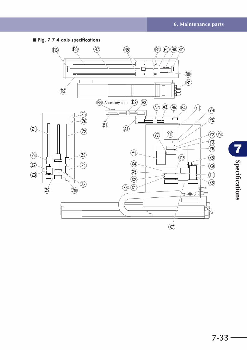
Specifi cations
7
7-33
■ Fig. 7-7 4-axis specifications
(Accessory part)
R2
R6 R3 R7 R5 R4 R9
R1
R8 R11
R10
Z3
Z7 Z4
Z5Z6
Z2
Z9
Z3
Z1
Z4
Z8Z10
B1
B6 B2 B3
A1
A2 A3
Y10
X12
B5Y9
Y5
Y2 Y4
Y3Y6
X8
X9
X6
X11
X7
Y7
Y1
X4
X5
X2
X3 X1
B4 Y11
6. Maintenance parts

Specifi cations
7
7-34
■ Fig. 7-8 3-axis specifications
Z15
Z14
Z16
(Accessory part)
R2
R6 R3 R7 R5 R4 R9
R1
R8 R11
R10
Z3
Z7 Z4
Z5Z6
Z2
Z9
Z3
Z1
Z4
Z8Z10
B1
B6 B2 B3
A1
A2 A3
Y10
X12
B5Y9
Y5
Y2 Y4
Y3Y6
X8
X9
X6
X11
X7
Y7
Y1
X4
X5
X2
X3 X1
B4 Y11
6. Maintenance parts

MEMO

Ver. 1.00Ver. 1.01
English manual Ver. 1.00 is based on Japanese manual Ver. 1.00.English manual Ver. 1.01 is based on Japanese manual Ver. 1.01.
Revision record
Manual version
Feb. 2008Mar. 2008
Issue date Description
Mar. 2008 Ver. 1.01This manual is based on Ver. 1.01 of Japanese manual.
© YAMAHA MOTOR CO., LTD. IM Operations
All rights reserved. No part of this publication may be reproduced in any form without the permission of YAMAHA MOTOR CO., LTD. Information furnished by YAMAHA in this manual is believed to be reliable. However, no responsibility is assumed for possible inaccuracies or omissions. If you find any part unclear in this manual, please contact YAMAHA or YAMAHA sales representatives.
User's Manual
Disk Handling Robot(3, 4-axis specifications)