yaskawa ac servo drives junma series - motortong.com · with yaskawa’s world-leading ... magnetic...
TRANSCRIPT

YASKAWA
AC SERVO DRIVESJUNMA SERIES
SJME SERVOMOTORSJDE SERVOPACK
YASKAWA

System Configuration 4
Selection of Devices 5
Servomotors 8
SERVOPACKs 10
Connection Diagram 14
Installation 20
Cables / Peripheral Devices 24
Selection of Servomotor Size 35
Connection to Host Controller 42
Product Standard Life 43
Terminology 44
FAQs 45
Revision History 46
C O N T E N T S
AC SERVO DRIVESJUNMA SERIES
2 3
32UnpackingRemove the SERVOPACK from the box.
Reference pulse settingSelect the reference pulse switch for your of the controller.No parameter settings and gain adjustments are needed.
1 4Installation and wiringConnect the cables for thepower supply, signal lines, and a motor.
Fast & Easy SetupSettings are easy to make, so setup time is reduced.
With Yaskawa’s world-leading servo drive technology, we are proud to introduce the Junma series for a wide range of applications.Following our policy to make user-friendly products, the Junma series is different from conventional models, because no more parameter settings and no more servo adjustments are required; therefore, the setup and test runs are greatly reduced. Also, the Junma series has the standard servo characteristics such as high response, high speed, high torque, and high accuracy.Try Yaskawa’s Junma series to improve your system so that it better suits your needs.
Setup completionThe motor is ready to run with the reference from the controller. The required torque is possible even at a high-speed rotation of 4500 min .-1
AttachedScrewdriver
4 5
Selection of DevicesSelection of DevicesSystem ConfigurationSystem Configuration
Sel
ectio
n of
Dev
ices
Sys
tem
Con
figur
atio
n
Servomotor
Without brake With brakeSJME-01AMA41SJME-02AMA41SJME-04AMA41SJME-08AMA41
SJME-01AMA4CSJME-02AMA4CSJME-04AMA4CSJME-08AMA4C
100W200W400W750W
Name LengthType/Model Specifications Manufacturer Contact
Servomotor main circuit cables with connectors at both ends (for relay)*1
Connectors for servomotor main circuit cables*2
Encoder cables with connectors at both ends (for relay)*1
Connectors for encoder cables*2
Cables for I/O signals
Connectors for battery case/regenerative unit*2
Tool to remove wires*2
Connectors for I/O signals(for CN1)*2
No brake
SERVOPACK end (for CN2)
SERVOPACK end (for CNB)
Motor end
With brakes
Motor end
Fujix Co., Ltd
ShanghaiJ.S.T(SHANGHAI)CO.,LTD.
Hong KongJ.S.T(H.K.) CO.,LTD.
ShanghaiMolex Interconnect(Shanghai)Co.,Ltd
ShenzhenMolex Hong Kong China Ltd.,Shenzhen Office
Molex Japan Co., Ltd
Molex Japan Co., Ltd
Sun-Wa Technos Corporation
Sun-Wa Technos Corporation
JST. Mfg. Co., Ltd.
Sumitomo 3M Ltd.
Sumitomo 3M Ltd.
For CNA
5m10m5m10m
5m
10m
1m2m3m
-
- - -
- - -
-
-
-
-
-
-
-
-
JZSP-CHM000-05JZSP-CHM000-10
JZSP-CHI003-01JZSP-CHI003-02JZSP-CHI003-03
JZSP-CHM030-05JZSP-CHM030-10
JZSP-CHP800-05
JZSP-CHP800-10
J-FAT-OT
MagneticContactor Noise Filter AC Reactor
SJDE-01APASJDE-02APASJDE-04APASJDE-08APA
0.400.751.22.2
4
816
0KLK015.T(15Arms)
0KLK030.T(30Arms)
HI-11JX5052X5053X5054X5056
FN2070-6/07
FN2070-10/07
FN2070-16/07
R・C・M-601BQZ-4
HI-15J
30
60
Contact
3M
*1: Contact your Yaskawa representative for the servomotor main circuit or the encoder cables of 3m, 15m, and 20m.*2: Connectors for CNA, CNB, CN1, and CN2 are sold separately.
Connectors at the motor end are also sold separately. The customer must provide these connectors.*3: Refer to page 27 for a list of models of crimping tools.*4: Refer to the list on page 34 for contact information.
* 4
Varistor
Encoder cable (for relay)
Never open the protective cover forthe connector.Do not use the connector since theconnector is reserved for adjustmentby the manufacturer.If the connector is used, aSERVOPACK failure may result.
L1 L2
REF
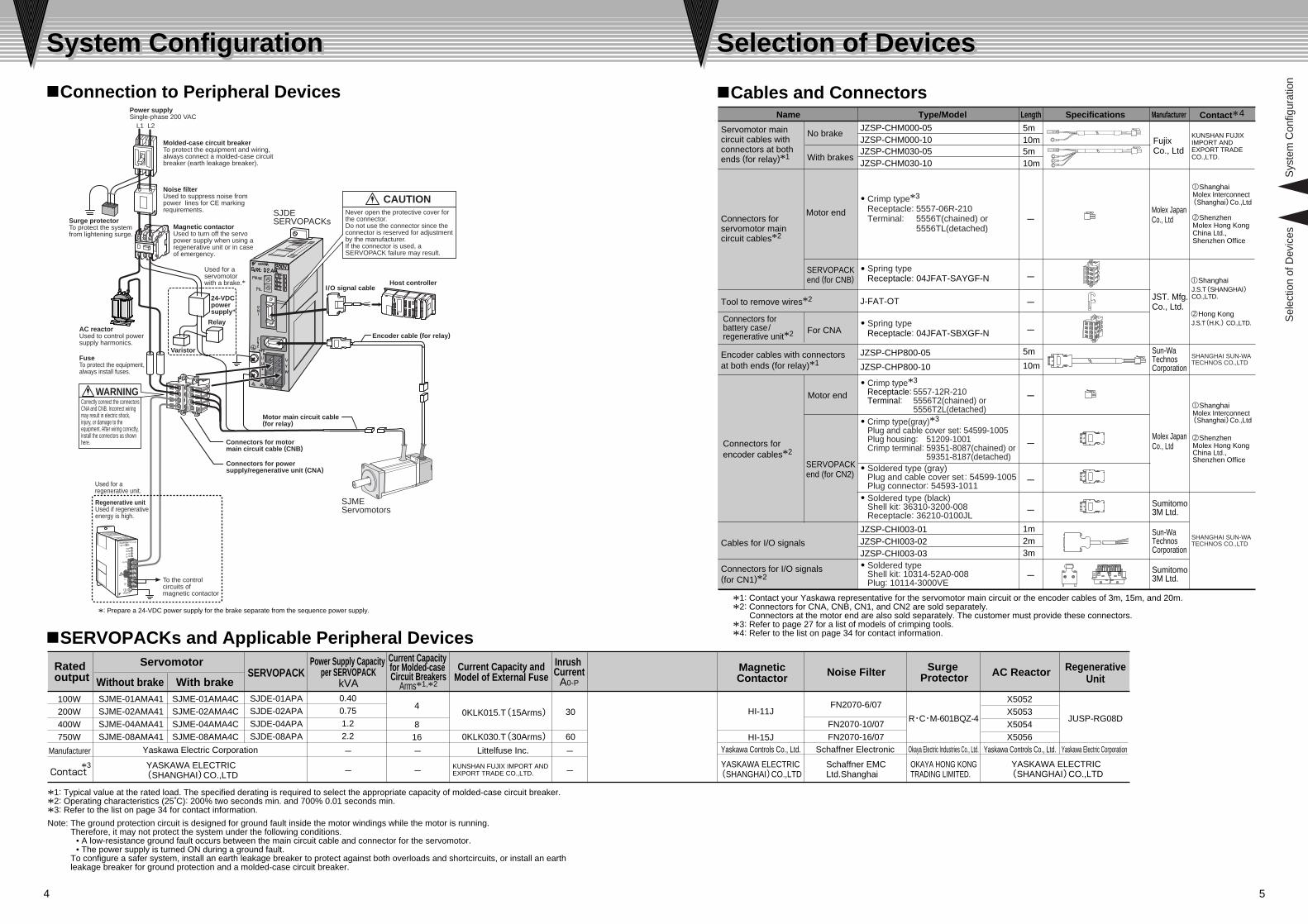
*: Prepare a 24-VDC power supply for the brake separate from the sequence power supply.
Used for a regenerative unit.
C
089A
B DEF
45 3267 1
C
089A
B DEF
45 3267 1
WARNING
CAUTION
Yaskawa Controls Co., Ltd.Littelfuse Inc. Yaskawa Controls Co., Ltd.Schaffner Electronic Okaya Electric Industries Co., Ltd.Manufacturer
Ratedoutput SERVOPACK
Inrush CurrentA0-P
Power Supply Capacity per SERVOPACK
kVA
Current Capacity andModel of External Fuse
Current Capacity for Molded-case Circuit Breakers
Arms*1,*2
Schaffner EMC Ltd.Shanghai
KUNSHAN FUJIX IMPORT AND EXPORT TRADE CO.,LTD.
OKAYA HONG KONG TRADING LIMITED.
*3
RegenerativeUnit
JUSP-RG08D
Yaskawa Electric Corporation
YASKAWA ELECTRIC (SHANGHAI)CO.,LTD
KUNSHAN FUJIX IMPORT AND EXPORT TRADE CO.,LTD.
SHANGHAI SUN-WA TECHNOS CO.,LTD
YASKAWA ELECTRIC (SHANGHAI)CO.,LTD
YASKAWA ELECTRIC (SHANGHAI)CO.,LTD
*1: Typical value at the rated load. The specified derating is required to select the appropriate capacity of molded-case circuit breaker.*2: Operating characteristics (25˚C): 200% two seconds min. and 700% 0.01 seconds min.*3: Refer to the list on page 34 for contact information.
Note: The ground protection circuit is designed for ground fault inside the motor windings while the motor is running. Therefore, it may not protect the system under the following conditions.
• A low-resistance ground fault occurs between the main circuit cable and connector for the servomotor.• The power supply is turned ON during a ground fault.
To configure a safer system, install an earth leakage breaker to protect against both overloads and shortcircuits, or install an earth leakage breaker for ground protection and a molded-case circuit breaker.
SHANGHAI SUN-WA TECHNOS CO.,LTD
ShanghaiMolex Interconnect(Shanghai)Co.,Ltd
ShenzhenMolex Hong Kong China Ltd.,Shenzhen Office
Connection to Peripheral Devices Cables and Connectors
Noise filterUsed to suppress noise from power lines for CE marking requirements.
Molded-case circuit breakerTo protect the equipment and wiring, always connect a molded-case circuit breaker (earth leakage breaker).
Magnetic contactorUsed to turn off the servo power supply when using a regenerative unit or in case of emergency.
Used for a servomotor with a brake.*
Power supplySingle-phase 200 VAC
I/O signal cableHost controller
SJDESERVOPACKs
Regenerative unitUsed if regenerative energy is high.
FuseTo protect the equipment,always install fuses.
AC reactorUsed to control power supply harmonics.
Surge protectorTo protect the system from lightening surge.
Connectors for motor main circuit cable (CNB)
Connectors for power supply/regenerative unit (CNA)
Motor main circuit cable(for relay)
SJMEServomotors
To the control circuits of magnetic contactor
24-VDCpower supply*
Relay
Correctly connect the connectors CNA and CNB. Incorrect wiring may result in electric shock, injury, or damage to the equipment. After wiring correctly, install the connectors as shown here.
SERVOPACKs and Applicable Peripheral Devices
Yaskawa Electric Corporation
Surge Protector
Crimp type*3
Receptacle: 5557-06R-210Terminal: 5556T(chained) or
5556TL(detached)
Spring typeReceptacle: 04JFAT-SAYGF-N
Crimp type*3
Receptacle: 5557-12R-210Terminal: 5556T2(chained) or
5556T2L(detached)Crimp type(gray)*3
Plug and cable cover set: 54599-1005Plug housing: 51209-1001Crimp terminal: 59351-8087(chained) or
59351-8187(detached)Soldered type (gray)Plug and cable cover set : 54599-1005Plug connector: 54593-1011Soldered type (black)Shell kit: 36310-3200-008Receptacle: 36210-0100JL
Soldered typeShell kit: 10314-52A0-008Plug: 10114-3000VE
Spring typeReceptacle: 04JFAT-SBXGF-N

6
<Allowable Load Inertia Moment and Allowable Regenerative Frequency with Regenerative Unit >
Power Supply Voltage: 230 VPower Supply Voltage: 200 V
0 4500
2.1
3.6
6.9
30000
10
8
6
4
2Regenerative unit not required.
SJDE-08(750W)
0 4500
1.1
1.9
3.0
30000
5
4
3
2
1Regenerative unit not required.
SJDE-04(400W)
0 450030000
0.60.5
0.4
0.3
0.2
0.1
SJDE-01(100W)
0 4500
3.7
5.3
8.5
30000
10
8
6
4
2 Regenerative unit not required.
SJDE-08(750W)
0 450030000
5
1
2
3
4
Regenerative unit not required.
SJDE-04(400W)
SJDE-02(200W)
1.8
2.8
3.9
1.3
2.4
Load
mom
ent o
f ine
rtia
( ×10
-4 k
g m
2 )
Speed (min-1)
Load
mom
ent o
f ine
rtia
( ×10
-4 k
g m
2 )
Speed (min-1)
Load
mom
ent o
f ine
rtia
( ×10
-4 k
g m
2 )
Speed (min-1)
Load
mom
ent o
f ine
rtia
( ×10
-4 k
g m
2 )
Speed (min-1)
Load
mom
ent o
f ine
rtia
( ×10
-4 k
g m
2 )
Speed (min-1)
Load
mom
ent o
f ine
rtia
( ×10
-4 k
g m
2 )
Speed (min-1)
Load
mom
ent o
f ine
rtia
( ×10
-4 k
g m
2 )
Speed (min-1)
Load
mom
ent o
f ine
rtia
( ×10
-4 k
g m
2 )
Speed (min-1)
0 45003000
SJDE-01(100W)
0
0.60.5
0.4
0.3
0.2
0.1
Regenerative unit not required.
Regenerative unit not required.
Regenerative unit not required.
0 45003000
30 rotations/min
60 rotations /min
30 rotations/min
60 rotations /min
30 rotations/min
12 rotations/min
60 rotations /min
12 rotations/min
6 rotations/min
30 rotations/min 12 rotations/min
6 rotations/min
30 rotations/min
30 rotations/min
12 rotations/min
60 rotations /min
0 4500
0.8
1.8
30000
3
2.5
2
1.5
1
0.5
0
3
2.5
2
1.5
1
0.5 Regenerative unit not required.
SJDE-02(200W)
Note: An overvoltage alarm will occur without a required regenerative unit.
The graphs below show the capacity absorbed regenerative energy and allowable regenerative frequency of the SERVOPACKs with regenerative units connected.The graphs show values for horizontal axis. For the vertical axis, refer to the JunmaSize+: AC Servomotor Selection Software.
Selection of DevicesSelection of Devices
Precautions when Selecting Peripheral DevicesRegenerative Units
The rotational energy of driven machines, including servomotor, is returned to the SERVOPACK as electric power. This is called regenerative power. The power is absorbed by the smoothing capacitor. When the capacitor has reached its limit in power absorption, the excess is then consumed by the regenerative unit.The servomotor is driven in the regeneration state in the following circumstances:
• While decelerating to a stop during acceleration and deceleration operation.• During continuous operation on the vertical axis.• During continuous operation with the servomotor rotated from the load side (negative load).

7
A magnetic contactor is required to make the AC power to SERVOPACK ON/OFF sequence externally. Be sure to attach a spark killer to the excitation coil of the magnetic contactor.
If selecting a molded-case circuit breaker, observe the following precautions.
• Do not touch the regenerative units as they reach high temperatures. Use heat-resistant, non-flammable wiring and make sure that the wiring does not touch the units. For connecting wire size when connecting a unit, refer to P16.
• The regenerative unit has three error detection functions: regenerative resistor burnout, regenerative transistor failure, and overvoltage detection. When these functions are tripped, the built-in alarm relay will operate and the C1 and C2 output terminals of the regenerative unit will be opened.
• Construct a sequence so that the power supply (through L1 and L2) to the SERVOPACK will be always shut OFF when the alarm relay operates. Two to three seconds are required to reset the alarm relay once the alarm relay operates. The alarm state will return to normal when the main capacitor in the SERVOPACK finishes discharging.
• The instantaneous maximum output of SERVOPACK is approximately 3 times the rated output. The output can last up to 3 seconds. Accordingly, select a molded-case circuit breaker whose breaking time is 5 seconds or more at 300% of SERVOPACK rated current. The general-purpose low-speed acting molded-case circuit breakers are applicable.
• The consumption of other controllers must be considered when selecting a molded-case circuit breaker.• The power-supply capacity per SERVOPACK when using a servomotor is described in nSERVOPACKs
and Applicable Peripheral Devices on page 4. If using several SERVOPACKs, select a molded-case circuit breaker with a capacity larger than the effective load current, which is calculated from the total power supply capacity.
• The allowable inrush current for a low-speed acting molded-case circuit breaker is approximately 10 times the rated current for 0.02 seconds.
• If several SERVOPACKs are being used at the same time, select a molded-case circuit breaker with an allowable current (20 ms) greater than the total inrush current of the SERVOPACK.
• Refer to nSERVOPACKs and Applicable Peripheral Devices on page 4 for more information on the SERVOPACK's inrush current.
• Install a noise filter on the power supply line for peripheral equipment as necessary.• Use a noise filter to prevent noise interference. If the equipment is to be used near private houses or may
receive noise interference, install a noise filter on the input side of the power supply line. Because the SJDE SERVOPACK is designed as an industrial device, it provides no mechanism to prevent noise interference.
• Install the input reference device and noise filter as close to the SERVOPACK as possible.
<Caution>
<Maximum Input Current >
< Inrush Current >
Sel
ectio
n of
Dev
icesMolded-case Circuit Breaker (MCCB)
Noise Filter
Magnetic Contactor
• It is recommended to use a general-purpose circuit breaker of the rated current 200 mA or more, or a circuit breaker for inverters (for high-frequency).
• High-frequency current may leak through the armature of a servomotor when switching in the SERVOPACKs.
Earth Leakage Breaker

8
VoltageDescription01 02
200 VAC04 08
Applicable SERVOPACKRated Output*1
Rated Torque*1,*2
Instantaneous Peak Torque*1
Rated Current*1
Instantaneous Max. Current*1
Rated Speed*1
Max. Speed*1
Torque ConstantRotor Moment of InertiaRated Power Rate*1 Rated Angular Acceleration*1
Time Rating
Thermal Class
Vibration Class
Withstand Voltage Insulation ResistanceEnclosure
Impact Resistance
Vibration Resistance
01100
0.3180.9550.842.5
02200
0.6371.911.13.3
30004500
044001.273.822.06.0
087502.397.163.711.1
0.4130.063416.0
50200
Continuous
B
15µm or below
1500 VAC for one minute500 VDC, 10 MΩ min.
0.6450.33012.3
19300
0.6820.60326.7
21100
0.6991.5038.1
15900
Description
*: To obtain the motor moment of inertia with a brake, add the holding brake moment of inertia to the rotor moment of inertia. The rated power rate and angular acceleration of the motor will change according to the motor moment of inertia.
Notes: 1 The holding brake is only used to hold the load and cannot be used to stop the servomotor.2 Do not use the holding brake when the servo is on. Failure to observe this caution may result in an overload in the SERVOPACK or a
decrease in the brake life.
01 0224 VDC ±10%
04 08Rated VoltageHolding Brake Moment of Inertia*CapacityMin. Holding Torque (Static Friction Torque)Coil ResistanceRated CurrentBrake Release TimeRise Time for Holding Torque
kgm2 ×10-4
W
Nm
Ω(at 20˚C)
A(at 20˚C)
ms
ms
0.00756
0.31896
0.25
0.0646.91.2783
0.2980 max.100 max.
0.1717.72.3975
0.32
How to Read a Gragh of Speed and Torque Characteristics
Spe
ed (
min
-1)
Spe
ed (
min
-1)
Spe
ed (
min
-1)
Spe
ed (
min
-1)
Spe
ed (
min
-1)
ServomotorsServomotors
Impact acceleration: 490 m/s2 in three directions — vertical,side to side, and front to back.Impact occurrences: 2Vibration acceleration: 49 m/s2 in three directions — vertical, side to side, and front to back.
Totally enclosed, self-cooled, IP55 (excluding shaft opening and connectors)
–Motor output at the rated operating pointTorque at the rated operating pointMaximum instantaneous torque of the motorCurrent flowing to the motor at the rated operating pointMaximum instantaneous current that is allowed to flow to the motorSpeed at the rated operating pointHighest possible speedGenerated torque ratio for current flowing to the motorInertia moment at the rotor shaftMotor output per unit timeThe theoretical angular acceleration(also called torque-to-inertia ratio) at the rated torque"Continuous rating" means that the temperature of the servomotor in continuous operation under specified conditions will not exceed a specified temperature or other limitation.Highest allowable temperature for armature winding: 130˚CThe maximum vibration amplitude of the motor expressed in units of micrometers on the condition that the vibration is measured with a vibrometer parallel to the shaft and in two directions perpendicular to the shaft.
––
Level of protection from dust and water dropsImpact resistance of the motor in three directions (up and down, left and right, and back and forth) with the motor shaft mounted horizontallyVibration resistance of the motor in three directions (up and down, left and right, and back and forth) with the motor shaft mounted horizontally
–––
Torque against an external force to hold the shaftResistance of the built-in coil in the brakeCurrent that flows when the brake is releasedTime from when the power for the holding brake is turned on until the brake is released.Time from when the power for the holding brake is turned off until the brake reaches the set torque.
Ratings and Specifications
Holding Brake Specifications
Speed / Torque Characteristics
Servomotor Model: SJME- ASJDE- AWNmNmArmsArmsmin-1
min-1
Nm/Armskgm2 ×10-4
kw/s
rad/s2
Servomotor Model:SJME- A
*1: These items and speed/ torque characteristics quoted in combination with an SJDE SERVOPACK are at an armature winding temperature of 100˚C. Other values quoted at 20˚C.
*2: The rated torques listed here are the values for the continuous allowable torque at 40˚C with an aluminum heatsink(250 mm × 250 mm × 6 mm) attached.
A B
SJME-04A
Torque(Nm)
3000
4000
2000
1000
5000
00 1 2 3 4
The output torque will decrease if the speed exceeds the rated speed.
Rated torqueThe same torque is output at any rotation speed.
B. Repetitive operating rangeRange where the motor can be operated for a short time, provided that the effective torque of the motor is within the continuous operating range.
A. Continuous operating range Safe range allowing the continuous operation of the servomotor. The effective torque must be within this range.
Rated operating point
SJME-01A SJME-02A SJME-04A SJME-08A
Torque(Nm) Torque(Nm) Torque(Nm) Torque(Nm)0 0.25 1.000.750.50
0
3000
4000
2000
1000
5000
A B A B
3000
4000
2000
1000
5000
00 0.5 2.01.51.0
A B
3000
4000
2000
1000
5000
00 1 2 3 4
3000
4000
2000
1000
5000
0
A B
0 2 4 6 8
Note: Solid lines show the torque/speed characteristics of the servomotor at 200 VAC, and the broken lines show them at 230 VAC.

9
2
5
3 1
123456
6 4
123456
789101112
Motor Connector Specifications
Plug:5559-06P-210
Terminal (No.1 to 3, 5, 6): 5558T(chained) or 5558TL(detached)
Grounding Pin (No.4): 30490-2002(chained) or 30490-2012 (detached)(Manufacture: Molex Japan Co., Ltd)
Plug:5559-12P-210
Terminal:5558T2(chained) or 5558T2L(detached)(Manufacture: Molex Japan Co., Ltd)
Encoder Connector Specifications
Phase UPhase VPhase W
F G––
RedWhiteBlue
Green/Yellow––
Phase UPhase VPhase W
F GBrakeBrake
RedWhiteBlue
Green/YellowRed
Black
No brake With brake
1.8
3
3
46 dia.2-4.3 dia.
Cross Section A-A
TypeSJME-
Approx. MasskgL LL
01AMA4101AMA4C
119164
94139
0.50.8
123456789101112
PG5VPG0V(GND)
Phase A+Phase A–Phase B+Phase B–Phase /ZPhase UPhase VPhase W
–FG
RedBlackBlue
Blue/WhiteYellow
Yellow/WhitePurpleGray
GreenOrange
–Shield
LA dia.4-LZ dia.
Cross Section A-A
3
5
5
TypeSJME-
Approx. MasskgL LL LR
02AMA4102AMA4C04AMA4104AMA4C08AMA4108AMA4C
125.5165.5
95.5135.5
30
40
LG
6
8
LE
3
3
S
14
16
LB
50
70
LC
60
80
LD
35
–
–
–
–
LF
20
LA
70
90
LZ
5.5
7
QK
20
30
148.5188.5
118.5158.5
173216
133176
0.91.5
1.31.92.63.5
Ser
vom
otor
s
0-0.011
0-0.011
0-0.039
0-0.046
Dimensions Units: mm
100W
200W to 750W
40
LC
Encoder cable
Servomotor main circuit cable
Encoder connector
300±30
300±30
LLL
LG LE
0.06 dia. A
LB d
ia.S
dia
.
A0.03
Motor connector
0.08 A
A
A
LDLF di
a.
QK
LR
0.08 A
A
Encoder connector
Servomotor main circuit cable
Encoder cable
300±30
300±30
0.03
A
A
2.55
25LLL
0.06 dia. A
14
Motor connector
Holding brake (de-energization operation)
Note: Only for servomotors with brakes Holding brake torque = Motor rated torque
Power supply: 24 VDC
8dia
.0 -0.
009
30di
a.0 -0
.033
Holding brake (de-energization operation)Power supply: 24 VDC
Note: Only for servomotors with brakes Holding brake torque = Motor rated torque

10
SERVOPACK model SJDE- Description01APA 02APA 04APA 08APAMax. applicable servomotor capacity [kW]
Cooling methodOperating temperatureOperating humidityStorage temperatureStorage humidity
Installation site
AltitudeVibration resistanceShock resistance
Operating conditions
Power loss at rated output [W]
Input control method
Output control method
VoltageFrequencyCapacity at rated output [kVA]
Input power supply (for main circuit and control circuit)
Input signal for reference
Pulse type
Pulse resolution
Clear input signalServo ON input signal
Alarm output signal
Brake output signal
Origin output signal
Dynamic brake (DB)
LED displayReference filter
Regenerative processing
0.1 0.2 0.4 0.75
0.40 0.75 1.2 2.2
14 16 24 35
0.6×10⁻⁴Allowable load inertia [kgm2]*1 3×10⁻⁴ 5×10⁻⁴ 10×10-4
Select one of the following signals:1. CCW + CW2. Sign + pulse train3. CCW + CW (logic reversal)4. Sign + pulse train (logic reversal)
Capacitor-input type, single-phase full-wave rectification with resistance to prevent inrush currents.PWM control, sine wave power driven system
Feedback Analog output encoder
Select one of the following signals:1. 1000 pulses/rev
(Open collector/line driver) 75 kpps max.2. 2500 pulses/rev
(Open collector/line driver) 187.5 kpps max.3. 5000 pulses/rev (Line driver) 375 kpps max.4. 10000 pulses/rev (Line driver) 750 kpps max.
Single-phase 200 V to 230 VAC, +10% to –15%50/60Hz ±5%
Clears the positioning error when turned ON.Turns the servomotor on or off.OFF if an alarm occurs.Note: OFF for 2s when power is turned ON.
External signal to control brakes. Turn ON to release the brake.
Positioning completed output signal
ON if the current position is equal to the reference position ± 10 pulses.ON if the motor is at the origin. (Width: 1/500 rev)Note: Use the pulse edge that changes the signal from OFF
to ON.
Optional (If the regenerated energy is too large, install a regenerative unit.)
5 (PWR, REF, AL1, AL2, AL3)Select one of eight levels with FIL switch.Forced cooling (built-in fan)0˚C to +55˚C90% RH or less (with no condensation)–20˚C to +70˚C90% RH or less (with no condensation)
Operated at main power OFF, servo alarm, servo OFF.(OFF after motor stops; ON if the motor power is off.)
• Free of corrosive gases• Free of dust and iron powder• Clean and dry1000 m or below4.9m/s2
19.6m/s2
Designated pulse type and pulse resolution with PULSE switch.
Motor capacity that the SERVOPACK can drive.
Continuous output current [Arms] 0.84 1.1 2.0 3.7 Current that the SERVOPACK can output continuously.
Instantaneous max. output current [Arms] 2.5 3.3 6.0 11.1 Maximum current that the SERVOPACK can output
instantaneously.
Power supply capacity required to operate a motor at the rated output.
Electric power emitted as heat from the SERVOPACK while operating the motor at the rated torque and rated speed.
Type of pulse train signal to drive motor, input into the SERVOPACK.For CCW+CW, input both forward and reverse rotation pulse trains.
Number of reference pulses required to rotate the motor one turn
Only one point of origin per rotation
Method that stops the motor by short-circuiting the internal circuit of the SERVOPACK.
Function to consume rotational power generated when the motor is rotated by external force. This function is required for a high load moment of inertia.
Protection*2
Speed errors, overload, encoder errors, voltage errors, overcurrents, disablement of the built-in cooling fan, system errors.Note: No built-in circuit for ground protection.
–
–
–
–––
–
–
–––
–
–––
––
–
–
–
––
SERVOPACKsSERVOPACKsI/O
Sig
nals
Bui
lt-in
func
tions
Ratings and Specifications
*1: Be sure to use the motor with in the allowable load inertia moment.The operation of the motor will become unstable if the allowable load Inertia moment is exceeded.
*2: The ground protection circuit is designed for ground fault inside the motor windings while the motor is running. Therefore, it may not protect the system under the following conditions.
• A low-resistance ground fault occurs in the main circuit cable or in the connector of the cable for the servomotor.• The power supply is turned ON during a ground fault.To configure a safer system, install an earth leakage breaker to protect against both overloads and shortcircuits, or install an earth leakage breaker for ground protection and a molded-case circuit breaker.
Installation category (overvoltage category):Pollution degree: 2Protection class: IP1X (EN50178)
Speed or position detector fixed on the motor shaft opposite the load side.
Maximum allowable moment of inertia converted into the moment of inertia at the motor shaft of the machine.

11
SE
RV
OP
AC
Ks
Dimensions Units: mm
SJDE-01, 02 (100W, 200W)
SJDE-04 (400W)
SJDE-08 (750W)
(17)
5
105
7
5
140
35(4.5)
(5)
(14)
(5)
(28)
Cooling fan
Airflow
Airflow
2-M4 mounting holes
(Mou
ntin
g pi
tch)
Mounting Hole Diagram
Nameplate
(75)
YASKAWA ELECTRICMADE IN CHINA
105
5 740
140
513
0 ±
0.5
(14)
(17)
(4.5)
(5)
(5)
(33)
(75)
Cooling fan
AirflowNameplate
Airflow2-M4 mounting holes
(Mou
ntin
g pi
tch)
Mounting Hole Diagram
Visible ovutline
YASKAWA ELECTRICMADE IN CHINA
Nameplate5
145
140
130
± 0.
5
70
14
17
30
5
(75)
(4.5) (13)(5)
Airflow
Airflow
2-M4 mounting holes
(Mou
ntin
g pi
tch)
Mounting Hole Diagram
Visible outline
Cooling fanYASKAWA ELECTRIC
MADE IN CHINA
(35)
(44)
(17)
130
± 0.
5
130
120
4.5
12.5
15
105
(10)(5)
719
40
140
Ground terminal with 2 × M4 screws
4.5 dia.holes
CN1
CN2
CNA
CNB
200VYASKAWA
SJDE- 04 APA
PULSE
FIL
REF
AL1AL2AL3
C
089
AB DEF
45 3267 1
C
089
AB DEF
45 3267 1
CN1
CN2PWR
CNA CNB
L1
L2
+
U
V
W
-
130
120
12.5
15
4.5
105
(10)(5)
140
719
35Ground terminal with 2 × M4 screws
CN1
CN2
4.5 dia.holes
CNB
200VYASKAWA
SJDE- 02 APA
PULSE
FIL
REF
AL1AL2AL3
C
089
AB DEF
45 3267 1
C
089
AB DEF
45 3267 1
CN1
CN2PWR
L1
L2
+
U
V
W
-
CNA CNB
CNA
140
130
5(5
)
10(1
0)12
0
12.5
15
14 30
70
17
4.5CNA
CNB
CN1
CN2
4.5 dia.holes
200VYASKAWA
SJDE- 08 APA
PULSE
FIL
CN1
CN2PWR
CNA CNB
L1
L2
+
U
V
W-
REF
AL1AL2AL3
C
089
AB DEF
45 3267 1
C
089
AB DEF
45 3267 1
Ground terminal with 2 × M4 screws
12
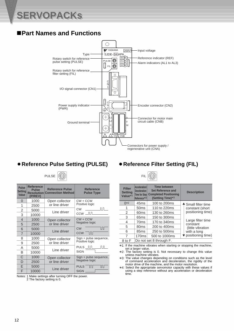
PulseSettingValue
Reference PulseConnection Method
ReferencePulse Type
Reference Pulse
Resolution(P/REV)
Description
Time betweenSet Reference and
Completed Positioning(Settling Time)*3
Acceleration/DecelerationTime for StepReference*4
FilterSettingValue*1
Do not set 8 through F.
Small filter time constant (short positioning time)
Large filter time constant (little vibration with a long positioning time)
0*2
1234567
8 to F
45ms50ms60ms65ms70ms80ms85ms170ms
100 to 200ms110 to 220ms130 to 260ms150 to 300ms170 to 340ms200 to 400ms250 to 500ms
500 to 1000ms
Open collector or line driver
Line driver
Open collector or line driver
Line driver
Open collector or line driver
Line driver
Open collector or line driver
Line driver
CW + CCWPositive logic
CW + CCWNegative logic
Sign + pulse sequence, Positive logic
Sign + pulse sequence, Negative logic
0123456789ABCDEF
10002500500010000100025005000100001000250050001000010002500500010000
PULSSIGN
CWCCW
CWCCW
PULSSIGN
SERVOPACKsSERVOPACKs
*1: If the machine vibrates when starting or stopping the machine, set a larger value.
*2: The factory setting is 0. Not necessary to change this value unless machine vibrates.
*3: The value changes depending on conditions such as the level of command acceleration and deceleration, the rigidity of the motor drive of the machine, and the motor resolution.
*4: Select the appropriate servomotor capacity with these values if using a step reference without any acceleration or deceleration time.
Part Names and Functions
Reference Pulse Setting (PULSE) Reference Filter Setting (FIL)
Notes: 1 Make settings after turning OFF the power.2 The factory setting is 0.
YASKAWA
CN1
SJDE- 04 APA
PULSE
FIL
REF
AL1
AL2
AL3
CN2
L1L2
+
-
U
V
W
PWR
CNBCNA
9 FA EB DC
4567
018
23
9 FA EB DC
4567
018
23
200V
Connectors for power supply / regenerative unit (CNA)
Connector for motor main circuit cable (CNB)
Encoder connector (CN2)
Alarm indicators (AL1 to AL3)
Reference indicator (REF)
Input voltageType
Rotary switch for referencefilter setting (FIL)
Rotary switch for referencepulse setting (PULSE)
Power supply indicator(PWR)
Ground terminal
I/O signal connector (CN1)
PULSE FILC
089
AB DEF
45 3267 1
C
089
AB DEF
45 3267 1

13
: Lit : OFF
AL1
AL2
AL3
AL1
AL2
AL3
AL1
AL2
AL3
AL1
AL2
AL3
AL1
AL2
AL3
AL1
AL2
AL3
AL1
AL2
AL3
AL1
AL2
AL3
AL1
AL2
AL3
Indicators Meaning of Alarm
Normal
Speed error
Overload
Overcurrent
Cooling fan inSERVOPACKstopped
System error
Rotary switch for reference pulse setting (PULSE) changed.Blinks at regular intervals.
Encoder error
Voltage error
Indicators Meaning of Alarm
Pin No. Symbol Signal Name1234
L1L2+-
Power supply input terminals
Regenerative unit connection terminals
Lit orange.
Blinks orange.
Lit green.
Blinks green.
OFF
OFF
ON
ON
—
Input
—
Input
Pin No. Symbol Signal Name12345
PG5VPG0V
A+A-B+
PG power supply +5 VPG power supply 0 V
Phase A+Phase A-Phase B+
Phase B-Phase /ZPhase UPhase VPhase W
Pin No. Symbol Signal Name678910
B-/ZUVW
Pin No. I/O I/OSymbol Signal Name1234567
CW, PULS/CW, /PULSCCW, SIGN/CCW, /SIGN
+24VIN/S-ON
SG-COM
External input power supplyServo ON
Output signal ground
Reverse rotation pulse, reference pulse
Forward rotation pulse, reference sign
InputInputInputInputInputInput
Output
InputInput
OutputOutputOutputOutputOutput
-
Pin No. Symbol Signal Name891011121314
Shell
CLR/CLRPCO
SG-PCOALM/BK
/COIN-
Position error pulse clear
Phase-C signalPhase-C signal ground
Servo alarmBrake
Positioning completedFG
Pin No. Symbol Signal Name1234
UVW-
Phase UPhase VPhase WNot used
Indicators* MotorPower
ReferencePulses
*: Lit yellow for 1 s when the clear signal is input.
SE
RV
OP
AC
Ks
Reference (REF) Alarm (AL1, AL2, and AL3)
Connector for Power Supply/Regenerative Unit (CNA)
I/O Signal Connector (CN1)
Encoder Connector (CN2)
Connector for Motor Main Circuit Cable (CNB)
1
2
3
4
A
43
21
N
1
2
3
4
A
43
21
N
14 8
19
9 1
210

14
Notes: 1 AVR1 : 24-VDC power supply for brakeAVR2 : 24-VDC power supply for sequenceSW1 : Power OFF switchSW2 : Power ON switchMC1 : Magnetic contactorRy1 : Relay for brake
2 The ground protection circuit is designed for ground fault inside the motor windings while the motor is running. Therefore, it may not protect the system under the following conditions.
• A low-resistance ground fault occurs between the main circuit cable and connector for the servomotor.• The power supply is turned ON during a ground fault.
To configure a safer system, install an earth leakage breaker to protect against both overloads and shortcircuits, or install an earth leakage breaker for ground protection and a molded-case circuit breaker.
Manufactures of Components
Connection DiagramConnection Diagram
Example
Spark killerFlywheel diodeRelay for brakeVaristor
Okaya Electric Industries Co., Ltd.:Toshiba Corp.: Omron Corp.: Nippon Chemi-Con Corp.:
CRE-505001NH42MY seriesTNR7V121K
Power supplySingle-phase 200 V to 230 VAC50/60Hz
AVR1*24-V power supply
Brake
V
WFG
U
V
W
U
V
W
U
/Z
B—
B+
A—
A+
PG0V
PG5VCW,PULS
/CW,/PULS
CCW,SIGN
/CCW,/SIGN
CLR
/CLR
PCO
SG-PCO
+24VIN
/S-ON
ALM
/BK
/COIN
SG-COM
2
3
4
1
2
3
4
5
6
7
8
9
10
12
1
2
3
4
1
2
3
4
8
9
5
6
7
Shell
ShellShield
Shield
Flywheel diode
10
11
12
13
14
1L1
L2
+
2
3
1
2
3
4
5
6
7
8
9
10
1
6
5
Varistor200 V to230 VAC
+24V
0V
Molded-case circuit breaker
SERVOPACK
Controller
Regenerative unitJUSP-RG08D
Servomotor
Encoder
Surge protector
Spark killer
L1
SW1
MC1
MC1
Ry1
Ry1
C1 C2 +
Y4
Y5
SW2
MC1
L2
75Ω
75Ω
75Ω
75Ω
75Ω
75Ω2.2kΩ
CNA CNB
CN1 CN2
3.4kΩ
+24V 0V
Noisefilter
Rea
ctor
AVR224-V powersupply
200 V to230 VAC
——
*: Prepare a 24-VDC power supply for the brake separate from the sequence power supply.

15
Main Circuit Wiring
SERVOPACK Main Circuit Wire Size and Tightning Torque
Symbol Name
Cable Types AllowableConductor
Temperature
PVC
IV
HIV
Normal vinyl cable
600-V vinyl cable
Temperature-resistant vinyl cable
–
60˚C
75˚C
AWG SizeNominal Cross
Section Diametermm2
ConductiveResistance
Ω /mm
Allowable Current atAmbient Temperature A
ConfigurationNumber ofwires/mm2
20—
18
16
14
0.5
0.75
0.9
1.25
2.0
19/0.18
30/0.18
37/0.18
50/0.18
7/0.6
39.5
26.0
24.4
15.6
9.53
6.6
8.8
9.0
12.0
23
5.6
7.0
7.7
11.0
20
30˚C 40˚C 50˚C
4.5
5.5
6.0
8.5
16
Con
nect
ion
Dia
gram
Cable Types
600-V Heat-resistant Vinyl Cables (HIV)
Note: The values in the table are only for reference.
• SJDE SERVOPACKs are suitable where the power supply is less than 5000 Arms (230 V rms max.).• SERVOPACKs must be used with UL-listed fuses or circuit breakers, in accordance with the National
Electrical Code (NEC).• Use 75 ˚C heat-resistant copper wires or an equivalent.
• Wire sizes are selected for three cables per bundle at 40 ˚C ambient temperature with the rated current.
• Use cables with a minimum withstand voltage of 600 V for main circuits.• If cables are bundled in PVC or metal ducts, consider the reduction ratio of the allowable current.• Use heat-resistant cables under high ambient or panel temperatures where normal vinyl cables
will rapidly deteriorate.• Do not use cables under continuous regenerative state.
The following table shows the wire size and allowable current for three cables. Use a cable whose specifications meet or are less than the values in the table.

16
CapacityW
SERVOPACKType
Terminal Symbol
100200400750
SJDE-01ASJDE-02ASJDE-04ASJDE-08A
L1, L2
HIV1.25mm2HIV1.25mm2
Wiring length: 20 m max.
HIV1.25mm2
Wiring length: 0.5 m max.HIV2.0mm2
M4 1.2 to 1.4Nm
U, V, W +, –
Connector Name and Symbol
I/O signalconnector
Encoder signalconnector
Item Specifications
Wire Size Terminal Screw Size Tightening Torque
HIV 2.0 mm2 min.
<Signal Line Wire Sizes>The following wires are used for the CN1 and CN2 connectors on the SERVOPACK.
CN2
CN1
Connection DiagramConnection Diagram
Power Supply Input Terminals (L1, L2), Motor Connection Terminals (U, V, W), and Regenerative Unit Connection Terminals (+, –)
Ground Terminal ( )
Note: Connectors are used for all wiring.
Use twisted-pair wires or shielded twisted-pair
wires.
3m
AWG24(0.2 mm2), AWG26(0.12 mm2),
AWG28(0.08 mm2)
8 mm dia. max.
Use the cables specified by Yaskawa or use
shielded twisted-pair wires.
20m
AWG22 (0.33 mm2) and AWG26 (0.12 mm2)
Used AWG22 for the encoder power supply and
AWG26 for signal lines.
9 mm dia. max.
Cable
Maximum cable length
Applicable wires
Finished cable outer diameter
Cable
Maximum cable length
Applicable wires
Finished cable outer diameter

17
• Only an electrical engineer should perform the wiring.
• Design the circuit so that both the /S-ON signal and the main-circuit power supply turn OFF at an emergency stop.
• An overtravel function is not provided for the SERVOPACK. To configure a safer system, include a function so that the /S-ON signal will turn OFF when the limit switch is activated.
• If the servomotor is used to drive a vertical axis, install a safety device such as a counterweight to prevent the workpiece from falling down when an alarm occurs. Failure to observe this precaution may result in injury or damage to the equipment from fallen workpieces.
• Use a molded-case circuit breaker and fuse to protect the power supply line from high voltage. The SJDE SERVOPACK connects directly to a commercial power supply without a transformer, so always use a circuit breaker and fuse to protect the SERVOPACK from accidental high voltage.
• The ground protection circuit is designed for ground fault inside the motor windings while the motor is running. Therefore, it may not protect the system under the following conditions.
A low-resistance ground fault occurs between the main circuit cable and connector for the servomotor.
The power supply is turned ON during a ground fault.
To configure a safer system, install an earth leakage breaker to protect against both overloads and shortcircuits, or install an earth leakage breaker for ground protection and a molded-case circuit breaker.
• The distance between a power line (such as a power supply line or servomotor cable) and a signal line must be at least 30 cm. Do not put the power and signal lines in the same duct, and do not bundle them together.
• The longer a pulse line is, the lower the maximum frequency of the line is.
• Customers must purchase a 24 VDC power supply with double-shielded enclosure.
• Install an interlock system in the circuit to avoid any accident when opening or closing the machine’s protective cover.
• To ground a SERVOPACK, follow these conditions.
Use as thick a cable as possible (HIV 2.0 mm2 or thicker) for grounding.
A ground resistance of 100Ω or less is recommended.
Ground to one point only.C
onne
ctio
n D
iagr
am
Wiring Precautions
Caution for Grounding
• For wiring, use the specified cables. Use cables that are as short as possible.
• Do not bend exessively or apply tension to cables. The conductor of a signal cable is very thin (0.08 to 0.12 mm2), so handle the cables carefully.
Caution for Cable
200VYASKAWA
SJDE- 04 APA
CTL
AL1
AL2
AL3
9
FA EB DC
45678
01
23
9
FA EB DC
45678
01
23
C
N
1
C
N
2
PWR
L1
L2
+
CNA CNB
U
V
W
-
200VYASKAWA
SJDE- 04 APA
FIL
PULSE
FIL
PULSE
FIL
PULSE
CTL
AL1
AL2
AL3
9
FA EB DC
45678
01
23
9
FA EB DC
45678
01
23
C
N
1
C
N
2
PWR
L1
L2
+
CNA CNB
U
V
W
-
200VYASKAWA
SJDE- 04 APA
CTL
AL1
AL2
AL3
9
FA EB DC
45678
01
23
9
FA EB DC
45678
01
23
C
N
1
C
N
2
PWR
L1
L2
+
CNA CNB
U
V
W
-
18
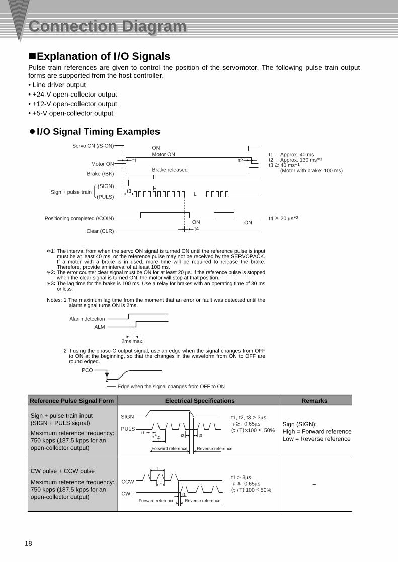
Pulse train references are given to control the position of the servomotor. The following pulse train output forms are supported from the host controller.• Line driver output• +24-V open-collector output• +12-V open-collector output• +5-V open-collector output
Servo ON (/S-ON)
Positioning completed (/COIN)
Clear (CLR)
Motor ON
Brake (/BK)
Sign + pulse train
Motor ON
Brake released
LH
H
ONON
ON
t4
t3
t2t1
*1: The interval from when the servo ON signal is turned ON until the reference pulse is input must be at least 40 ms, or the reference pulse may not be received by the SERVOPACK. If a motor with a brake is in used, more time will be required to release the brake. Therefore, provide an interval of at least 100 ms.
*2: The error counter clear signal must be ON for at least 20 µs. If the reference pulse is stopped when the clear signal is turned ON, the motor will stop at that position.
*3: The lag time for the brake is 100 ms. Use a relay for brakes with an operating time of 30 ms or less.
Notes: 1 The maximum lag time from the moment that an error or fault was detected until the alarm signal turns ON is 2ms.
2 If using the phase-C output signal, use an edge when the signal changes from OFF to ON at the beginning, so that the changes in the waveform from ON to OFF are round edged.
Reference Pulse Signal Form Electrical Specifications Remarks
Sign + pulse train input(SIGN + PULS signal) Sign (SIGN):
High = Forward referenceLow = Reverse reference
Maximum reference frequency: 750 kpps (187.5 kpps for an open-collector output)
CW pulse + CCW pulse
Maximum reference frequency: 750 kpps (187.5 kpps for an open-collector output)
Forward reference Reverse reference
t1t2 t3
T
SIGN
PULS
Forward reference Reverse referencet1
T
CW
CCW –
(SIGN)
(PULS)
Connection DiagramConnection Diagram
Explanation of I/O Signals
I/O Signal Timing Examples
t1: Approx. 40 mst2: Approx. 130 ms*3
t3 40 ms*1
(Motor with brake: 100 ms)
t1, t2, t3 > 3µs0.65µs
( /T)×100 50%
t1 > 3µs0.65µs
( /T) 100 50%
t4 20 µs*2
2ms max.
Alarm detection
ALM
PCO
Edge when the signal changes from OFF to ON
19
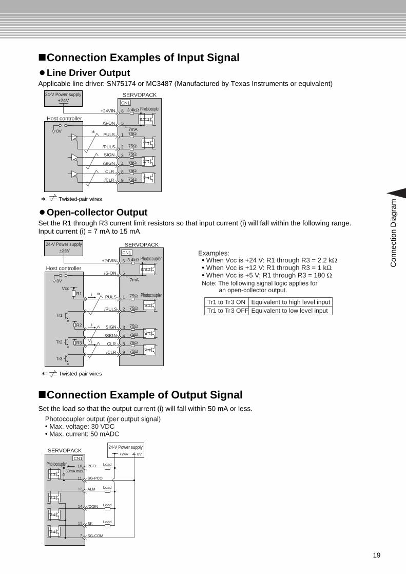
Applicable line driver: SN75174 or MC3487 (Manufactured by Texas Instruments or equivalent)
Set the R1 through R3 current limit resistors so that input current (i) will fall within the following range.Input current (i) = 7 mA to 15 mA
*: Twisted-pair wires
Examples:• When Vcc is +24 V: R1 through R3 = 2.2 kΩ• When Vcc is +12 V: R1 through R3 = 1 kΩ• When Vcc is +5 V: R1 through R3 = 180 ΩNote: The following signal logic applies for
an open-collector output.
Tr1 to Tr3 ON Equivalent to high level inputEquivalent to low level inputTr1 to Tr3 OFF
Con
nect
ion
Dia
gram
Connection Examples of Input Signal
Set the load so that the output current (i) will fall within 50 mA or less.
Photocoupler output (per output signal)• Max. voltage: 30 VDC• Max. current: 50 mADC
Connection Example of Output Signal
Line Driver Output
Open-collector Output
*: Twisted-pair wires
SERVOPACK24-V Power supply
Photocoupler Load
Load
Load
Load
1050mA max.
+24V 0V
11
7
13
14
12
SG-PCO
ALM
/COIN
BK
SG-COM
PCO
CN1
SERVOPACK
Photocoupler
Host controller
1
2
9
8
4
3
/PULS
SIGN
/SIGN
CLR
/CLR
PULS 75Ω7mA*
CN1
75Ω
75Ω
75Ω
75Ω
75Ω
6
5
3.4kΩ
/S-ON
+24VIN
0V
24-V Power supply+24V
Photocoupler1
2
9
8
4
3
/PULS
SIGN
/SIGN
CLR
/CLR
PULS*
VccR1 i
R2
Tr1
Tr2
Tr3
R3
i
i
75Ω
75Ω
75Ω
75Ω
75Ω
75Ω
SERVOPACK
Photocoupler
Host controller
7mA
CN1
6
5
3.4kΩ
/S-ON
+24VIN
0V
24-V Power supply+24V

20
InstallationInstallation
The service life of the servomotor will be shortened or unexpected problems will occur if the servomotor is installed incorrectly or in an inappropriate location. Always observe the precautions in this section when installing a servomotor.
• If the relay cables are connected to the motor, be sure to connect the end for the servomotor's main-circuit cables before connecting the end for the encoder cable. If the encoder cable's end is connected first, the encoder may become damaged because of the voltage differences between the Frame Ground (FG) pins on the servomotor and the grounding terminal of the SERVOPACK.
• If using cables that are not made by Yaskawa, ensure that connector pins and cables are correctly configured.
• Make sure there is no foreign matter (such as dust and metal chips) in the connector before connecting.• When handling a servomotor with its cables connected, hold the servomotor or the connectors and cables
will be damaged.
The protective structure of the servomotors is designed with an IP55 rating.• The servomotor can be used in a location that is subject to water drops, except for the connector and the
section where the shaft passes through.• Do not use the servomotor in a location that is subject to oil mist.
Counterclockwise
Through shaft section
Shaft
Flange
This refers to the gap where the shaft protrudes from the end of the motor.
Positive rotation of the servomotor is counterclockwise when viewed from the load.
Servomotor InstallationPrecautions
Installation Conditions
Waterproof Specifications
Direction of Servomotor Rotation
Note: Do not directly connect the servomotor to a commercial power line. This will damage the servomotor.
EnvironmentOperating temperature
Operating humidity
Installation sites
Storage conditions
Altitude
Environment0˚C to +40˚C without freezing
20% to 80%RH with no condensation
• Indoors
• Free of corrosive or explosive gases
• Well-ventilated and free of dust and moisture
• Facilitates inspection and cleaning
If the power cable is disconnected, store the motor under these conditions.
Temperature: -20˚C to +60˚C without freezing
Humidity: 20% to 80%RH with no condensation
1000 m or below above sea level

21
Inst
alla
tion
The motor main circuit cable, encoder cable, and relay cable cannot be used for applications in which the cables are moved, twisted, or rotated to a small bending radius. The cable bending radius in the center of the cable must be a of 15 mm or larger. If the cables need to be bent, consult your Yaskawa representative.
Horizontal Vertical
Cable trap
Anticorrosive coating
Motor installation plate
Mounting screw
Washer
Nut
<Precautions>
Bending radiusR = 15
• The motor can be installed horizontally or vertically. If the motor is mounted vertically, provide a cable trap so that water drops do not enter the motor.If the motor is installed with the axis pointing up, take preventative measures so that oil does not splash on the motor from other parts of the machine such as the gearbox.
• Do not bend or pull excessively any cables, the lead openings, and the junctions of the cables. The cores in the encoder cable and the brake signal line in the main circuit cable are only 0.2 mm2 or 0.3 mm2. Be sure to protect them from stress.
• The end of the motor shaft is coated with an anticorrosive coating. Thoroughly remove the coating prior to installation, or it will not be possible to couple the motor to the mechanical system.
• Use the mounting holes (two for 100-W models and four for 200- to 750-W models) on the motor installation surface to secure the motor.
• Do not apply shock directly to the output shaft or encoder when mounting the motor, because the servomotor shaft is directly coupled to the encoder. The encoder may be damaged by the shock.
Installation Direction
Installation Method

22
Coupling
Measure this distance at four different positions on the circumference. The difference between the maximum and minimum measurements must be 0.03 mm or less.
Alignment Accuracy
Note: When measuring the difference, turn the motor and the coupling together.
Servomotor ModelSJME-
AllowableRadial Load
N
Distancefrom Flange
mm
Allowable Thrust LoadN
Direction A or B
01A
02A
04A
08A
78
245
245
392
54
74
74
147
20
25
25
35
Allowable Thrust Load
Distance from Flange
Allowable Radial Load
A
A
A
Perpendicularity between the flange face and output shaft
Run-out at the end of the shaft
Matching concentricity of the flange
A B
InstallationInstallation
Design the mechanical system so that, during operation, the thrust and radial loads applied to the servomotor shaft do not exceed the range shown in the table below.
The following diagram shows tolerances for the servomotor's output shaft and installation area.
0.03 mm
0.08 mm
0.06 dia. mm
Coupling to the Machine
Allowable Loads
Mechanical Tolerance TIR (Total Indicator Reading)
Observe the following precautions when coupling the servomotor with the drive axis of the machine.
• Align the shaft of the servomotor with the shaft of the equipment, and then couple the shafts.
• Make sure that the motor and the machine are accurately aligned.Failure to observe this caution may result in damage to the motor axis or deterioration of the standard life of the servomotor by an eccentric load. Keep the eccentric load as small as possible.
• A metal disk coupling designed for servomotors is recommended to maintain the response characteristics and durability of the servomotor.
• When attaching the coupling to the shaft of the servomotor, do not hammer the axis or near the encoder. Such shocks and vibrations may cause the encoder to malfunction.

23
Installation Site Notes
Installation in a control panel
Installation near a heating unit
Installation near a source of vibration
Installation at a site exposed to corrosive gas
SERVOPACK installation plate
M4 screw
200VYASKAWA
SJDE- 04 APA
PULSE
FIL
CTLAL1AL2AL3
1 72 63 54
CDEF
0 89
AB
1 72 63 54
CDEF
0 89
AB
CN1
CN2PWR
L1
L2
+
CNA CNB
U
V
W-
200VYASKAWA
SJDE- 04 APA
PULSE
FIL
CTLAL1AL2AL3
1 72 63 54
CDEF
0 89
AB
1 72 63 54
CDEF
0 89
AB
CN1
CN2PWR
L1
L2
+
CNA CNB
U
V
W-
200VYASKAWA
SJDE- 04 APA
PULSE
FIL
CTLAL1AL2AL3
1 72 63 54
CDEF
0 89
AB
1 72 63 54
CDEF
0 89
AB
CN1
CN2PWR
L1
L2
+
CNA CNB
U
V
W-
200VYASKAWA
SJDE- 04 APA
PULSE
FIL
CTLAL1AL2AL3
1 72 63 54
CDEF
0 89
AB
1 72 63 54
CDEF
0 89
AB
CN1
CN2PWR
L1
L2
+
CNA CNB
U
V
W-
50 mm min.
50 mm min.30 mm min. 10 mm min.
Inst
alla
tion
Be sure to keep a space between adjacent SERVOPACK units if they are mounted inside the control panel so that the units can be cooled.
SERVOPACK InstallationInstallation Conditions
Installation Method
Space between SERVOPACK Units
• Install the SERVOPACK perpendicular to the wall. The SERVOPACK contains a built-in fan for cooling and must be mounted in the specified direction.
• Connect the mounting holes securely to the mounting surface with M4 screws (two mounting holes).
Install a vibration isolator beneath the SERVOPACK to avoid subjecting it to vibration.Corrosive gas does not have an immediate effect on the SERVOPACK but will eventually cause the electronic components and contactor-related devices to malfunction. Take appropriate action to avoid corrosive gas.
Installation at a contaminated site
Take appropriate action to avoid any contaminants such as dust, iron particles, water drops, or oil mist. Contamination will cause the electronic components to malfunction.
Minimize the heat radiating from the heating unit as well as any temperature rise caused by natural convection so the temperature around the SERVOPACK does not exceed 55˚C.
Design the control panel size, unit layout, and cooling method so the temperature around the SERVOPACK does not exceed 55˚C.Note: The maximum ambient temperature for long-term reliability is 45˚C.
Airflow
Airflow
24
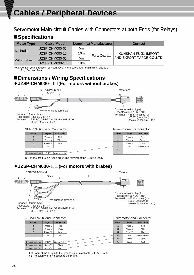
Servomotor Main-circuit Cables with Connectors at both Ends (for Relays)
Cable Model Contact
KUNSHAN FUJIX IMPORTAND EXPORT TARDE CO.,LTD.
Manufacturer
Fujix Co., Ltd
Motor Type Length (L)
No brake
With brakes
JZSP-CHM000-05
JZSP-CHM000-10
JZSP-CHM030-05
JZSP-CHM030-10
5m
10m
5m
10m
Wire ColorSignalPin No.
Red
White
Blue
—
Green/Yellow
Phase U
Phase V
Phase W
—
F G*
1
2
3
4
Crimped terminals
Wire ColorSignal
Red
White
Blue
Green/Yellow
—
—
Phase U
Phase V
Phase W
F G
—
—
Pin No.
1
2
3
4
5
6
1 2 34 5 6
SERVOPACK end
SERVOPACK end
SERVOPACK-end Connector Servomotor-end Connector
M4 crimped terminals
L1 4
1 4
Connector (crimp type)Receptacle:5557-06R-210Terminal: 5556T(chained) or
5556TL(detached)(Molex Japan Co., Ltd.)
Connector (crimp type)Receptacle:5557-06R-210Terminal: 5556T(chained) or
5556TL(detached)(Molex Japan Co., Ltd.)
Motor end
L
50mm
50mm
Motor end
M4 crimped terminals
*: Connect the FG pin to the grounding terminal of the SERVOPACK.
Wire ColorSignalPin No.
Red
White
Blue
—
Green/Yellow
Black
Black
Phase U
Phase V
Phase W
—
F G*1
Brake*2
Brake*2
Wire ColorSignal
Red
White
Blue
Green/Yellow
Black
Black
Phase U
Phase V
Phase W
F G
Brake
Brake
Pin No.
123456
1
2
3
4
Crimped terminals
Crimped terminals
Crimped terminals
SERVOPACK-end Connector Servomotor-end Connector
*1: Connect the FG pin to the grounding terminal of the SERVOPACK.*2: No polarity for connection to the brake.
1 2 3
4 5 6
Connector (crimp type)Receptacle: F32FSS-04V-KYTerminal: SF3F-01GF-P2.0 or SF3F-41GF-P2.0
(J.S.T. Mfg. Co., Ltd.)
Connector (crimp type)Receptacle: F32FSS-04V-KYTerminal: SF3F-01GF-P2.0 or SF3F-41GF-P2.0
(J.S.T. Mfg. Co., Ltd.)
Cables / Peripheral DevicesCables / Peripheral Devices
Specifications
Dimensions / Wiring SpecificationsJZSP-CHM000-oo(For motors without brakes)
JZSP-CHM030-oo(For motors with brakes)
Note: Contact your Yaskawa representative for the servomotor main-circuit cables of 3m, 15m, and 20m.

25
Connectors for Servomotor Main-circuit Cables
PartsType Manufacturer Contact
Molex JapanCo., Ltd.
Molex Interconnect(Shanghai)Co.,Ltd.ReceptacleTerminalCrimp type
Crimping tool
Model5557-06R-210
57027-5000
5556T(chained) or5556TL(detached)
Connectors for Battery Case, Regenerative Unit, and Servomotor Main-circuit Cables
Model Manufacturer Contact
04JFAT-SBXGF-N
04JFAT-SAYGF-N
J-FAT-OT
J.S.T. Mfg. Co., Ltd.
J.S.T.(SHANGHAI)CO LTD
J.S.T.(H.K) CO LTD
PartsTypeFor battery case/regenerative unit
For servomotor main-circuit cables
Tool to remove wires
Springtype
CNA connector
CNB connector
4A
JSTNY3 2 1
4 3 2 1
5.0815.24
20.4429.0434.24 6.76.7
13.213.2
29
7
20.3
A
4 3 2 1N
4
A
JSTRX321
4321
5.0815.24
20.4429.0434.24
29
A
4321
N
1 2 3
4 5 611.6
10.7
19.6
13.8
Cab
les
/ Per
iphe
ral D
evic
es
Specifications
Dimensions Units: mm
Dimensions Units: mm
Specifications
Power Supply/Regenerative Unit Connector04JFAT-SBXGF-N
Tool to Remove WiresJ-FAT-OT
Servomotor Main Circuit Cable Connector04JFAT-SAYGF-N
Shanghai
Shenzhen
Shanghai
Shenzhen
Molex Hong Kong China Ltd., Shenzhen Office

26
Encoder Cables with Connectors at both Ends (for Relay)
Contact
SHANGHAI SUN-WA TECHNOS CO.,LTD
Model Manufacturer
Sun-Wa Technos Corporation
Length (L)JZSP-CHP800-05
JZSP-CHP800-10
5m
10m
Pin No. Signal Wire ColorRed
BlackBlue
Blue/WhiteYellow
Yellow/WhitePurpleGray
GreenOrange
Shield wire
12345678910
Shell
PG5VPG0V(GND)
Phase A+Phase A—Phase B+Phase B—Phase /ZPhase UPhase VPhase W
—
Pin No. Signal Wire ColorRed
BlackBlue
Blue/WhiteYellow
Yellow/WhitePurpleGray
GreenOrange
—Shield
123456789
101112
PG5VPG0V(GND)
Phase A+Phase A—Phase B+Phase B—Phase /ZPhase UPhase VPhase W
—FG
SERVOPACK end
Plug and cable cover set : 54599-1005Plug housing : 51209-1001Crimped terminals: 59351-8087(chained) or
59351-8187(detached) (Molex Japan Co., Ltd.)
LMotor end
Receptacle : 5557-12R-210Terminal : 5556T2(chained) or
5556T2L(detached) (Molex Japan Co., Ltd.)
1 2 3 4 5 6
7 8 9 11 1210
1 2
9 10
Shield wire
Cables / Peripheral DevicesCables / Peripheral Devices
Specifications
Dimensions
Wiring Specifications
Note: Contact your Yaskawa representative for the encoder cables of 3m, 15m, and 20m.
• Crimp type (Gray)
Shell kit : 36310-3200-008Receptacle : 36210-0100FD
• Solder type (Black)

27
Connectors for Encoder Cables
Parts Manufacturer Contact
Molex Japan Co., Ltd.
Receptacle
Terminal
Crimping tool
Model5557-12R-210
57026-5000
5556T2(chained) or5556T2L(detached)
PartsType
Type
Manufacturer Contact
Molex Japan Co., Ltd.
Sumitomo 3M Ltd.
Plug and cable cover set
Plug and cable cover set
Plug connector
Receptacle
Shell kit
Plug housing
Crimping tool
Crimp terminalCrimp type(gray)
Crimp type
Soldered type (gray)
Soldered type (black)
Model
54599-100551209-1001
54599-1005
57401-5300
54593-1011
36210-0100FD
36310-3200-008
59351-8087(chained) or 59351-8187(detached)
26.4
1 2 3 4 5 6
7 8 9 11 1210
1 2
9
11 40
15 22.7
10
Cab
les
/ Per
iphe
ral D
evic
es
SpecificationsMotor End
SERVOPACK End
Motor End
SERVOPACK End
Dimensions Units: mm
Molex Interconnect(Shanghai)Co.,Ltd.
Molex Hong Kong China Ltd., Shenzhen Office
Molex Interconnect(Shanghai)Co.,Ltd.
Molex Hong Kong China Ltd., Shenzhen Office
SHANGHAI SUN-WA TECHNOS CO.,LTD
11.6
19.6
10.7
Shanghai
Shenzhen
Shanghai
Shenzhen

28
Cables for I/O Signals
Connectors for I/O Signals
Cable Model Length (L) Manufacturer Contact
Sun-Wa Technos Corporation
JZSP-CHI003-01
JZSP-CHI003-02
JZSP-CHI003-03
1m
2m
3m
PartsType Manufacturer Contact
Sumitomo 3M Ltd.
Shell kitPlug
Solderedtype
Models10314-52A0-00810114-3000VE
29.5 12.7
8.5
23.6
7.0
18.2
39.0
23.8
5.2
2.54
1.27
Pin No.2
Pin No.1
13.6
7.62
15˚1.27
18.2
5.1
( 6.6
) 19.3
( 2.9
)
2.3
12.7
9.1
7.5
3M
100L+10– 0
( 5.6
dia
.)
Connector(14P) : 10114-6000ELShell : 10314-52A0-008(Sumitomo 3M Ltd.)
Cable (black)HP-SB/20276SR AWG#28×7PUL20276 VW-1
Host controller endSERVOPACK end
LeadColorSignal Code Signal
CodeSignal Name Signal NameMarking
Dots DotsColorPin No.
Orange
Light gray
White
Yellow
BlackRed
BlackRed
BlackRed
Black
1234567
1
LeadColor
MarkingColor
Pin No.
Yellow
Pink
Orange
Light gray
-
RedBlackRed
BlackRed
BlackRed
89
1011121314
Shell
1
2
-
CW, PULS/CW, /PULSCCW, SIGN
/CCW, /SIGN+24VIN/S-ON
SG-COM
External input power supplyServo ON
Reverse rotation pulse, reference pulse
Forward rotation pulse, reference signal
CLR/CLRPCO
SG-PCOALM/BK
/COIN-
Position error pulse clear
Phase-C signalPhase-C signal ground
Servo alarmBrake
Positioning completedFG
Output signal ground
Cables / Peripheral DevicesCables / Peripheral Devices
Dimensions Units: mm
Specifications
Wiring Specifications
Specifications
Dimensions Units: mm
Shell Kit Plug
SHANGHAI SUN-WA TECHNOS CO.,LTD
SHANGHAI SUN-WA TECHNOS CO.,LTD

29
Model Specifications20A35A
Manufacturer
Yaskawa Controls Co., Ltd.
Contact
YASKAWA ELECTRICH (SHANGHAI) CO.,LTD.
HI-11J
HI-15J
Dimensions Mounting Hole Dimensions Terminal Symbols
9
35
7661
34.54.5a b
2U
1R S T
4410.1
13
8.2
41 74.5
78.5
8.2
10.4
4
Auxiliary contact terminal M3.5 Main contact terminal M3.5
Coil terminalM3.5
V W
2 × M4 mounting holes
345
524815
.5
NO
NC
Auxiliary Contact Structure
Dimensions Mounting Hole Dimensions Terminal Symbols
91
35
65
4.5
7654
9
39
R S
U WV
T
a b
45.515.3
51
8.2
9.6
3
Main contact terminal M4
Coil terminalM3.5
Auxiliary contact terminal M3.5
11.3 10.8
9.6
855029
1
2
4
8.25.2 35
57570
2 × M4 mounting holes
NONC
Auxiliary Contact Structure
Magnetic Contactor
NO
R
U
A1
1
2
NCA2
S
V
3
4
T
W
5
6
1
2
13
14
NO A1 NCA2
R
U
1
2
S
V
3
4
T
W
5
6
1
2
11
12
NO
R
U
A1
1
2
NCA2
S
V
3
4
T
W
5
6
1
2
21
22
3
4
13
14
Cab
les
/ Per
iphe
ral D
evic
es
Specifications
Dimensions Units: mmHI-11J
HI-15J

30
Cables / Peripheral DevicesCables / Peripheral Devices
Specifications
External Fuse
Model
15Arms600V
SJDE-01 to 04
Manufacturer ContactApplicableSERVOPACKs
RatedVoltage
FusingTime
RatedCurrent
Littelfuse Inc.Within 2 sat 200%
KUNSHAN FUJIX IMPORTAND EXPORT TARDE CO.,LTD.
KUNSHAN FUJIX IMPORTAND EXPORT TARDE CO.,LTD.
0KLK015.T30Arms SJDE-080KLK030.T
Model TypeScrew terminal, 2 polesL60030M2SQCopper box lug, 2 polesL60030M2C
38.1 10.31
36.49
76.2
31.75
Manufacturer Contact
Littelfuse Inc.
Fuse
Dimensions Units: mmFuse
Fuse Block
Fuse Block

31
Cab
les
/ Per
iphe
ral D
evic
es
SpecificationsModel Specifications
Single-phase 250 VAC, 6ASingle-phase 250 VAC, 10ASingle-phase 250 VAC, 16A
Manufacturer Contact
Schaffner Electronic
Schaffner ShanghaiCo.,LTD.
FN2070-6/07FN2070-10/07FN2070-16/07
Model AFN2070-6/07FN2070-10/07
113.5±1156±1
B103±0.3143±0.3
C94±1
130.5±1
D4.4±0.15.3±0.1
Side viewTop view
D
57.5±1
6 ±0.
1
45.4
±1.2
38±0.5
32.4
±0.5
8.4 ±
0.5
0.9 ±
0.125±0.2A CB
Contact terminal
Side viewTop view Contact terminal
P/N/E
140
+5
-0
57.6
±11.
2 ±0.
1
8.6 ±
0.540±0.2
7.4±0.1
51±0.266±0.385.5±1
4.4 ±
0.1
119 ±
0.5
109 ±
0.3
98.5
±1Noise Filter
P/N/E
140
+5
-0
Dimensions Units: mmFN2070-6/07, FN2070-10/07
FN2070-16/07

32
Cables / Peripheral DevicesCables / Peripheral Devices
Model Manufacturer ContactJUSP-RG08DResistanceAllowable regenerative energy
Regenerative operating voltage
Regenerative processing current
Error detection
Alarm output
50Ω
12W
380 Vdc
8 Adc
Disconnection of regenerative resistance, failure of regenerative transistor, or overvoltage
NC contact (Opens if a protective function is used.)Contact specifications: 250 VAC, 1.5A (inductive load)
Approx. mass : 1.0kg
625
50
160
1513
015
65
25
149
130(15.5)
Nameplate
6-dia. hole
M4 screw for ground terminal
(Y4)
(Y5)
YASKAWA
C1
C2
+(Y3)
-
AL-0V
AL-RE
RE-ON
POWER
REGENERATIVE UNITJUSP-RG08D
Regenerative Unit
Dimensions Internal Connection Diagram
4.2 dia. ±0.5
Case
Connection cables
11±1
28.5
±1.0
28±1
200+
30-0
5.5 ±
1.0
4.5 ±
0.5
41±1
1 2
1 2
Model Manufacturer ContactOkaya Electric Industries Co., Ltd.
OKAYA HONG KONG TRADING LIMITED
Single-phase 250 VAC
Specifications
RCM-601BQZ-4
Surge Protector (For lightning surge protection)
M4 screw for external terminal
Specifications
Specifications
Dimensions Units: mm
Dimensions Units: mm
Yaskawa Electric Corporation
YASKAWA ELECTRIC (SHANGHAI) CO.,LTD.