yasser k reza zahedi - eprints.utm.myeprints.utm.my/id/eprint/78632/1/yasserkrezapfke2016.pdf ·...
TRANSCRIPT

ARTIFACT PATHS REMOVAL ALGORITHM FOR ULTRA-
WIDEBAND CHANNELS
YASSER K REZA ZAHEDI
UNIVERSITI TEKNOLOGI MALAYSIA

ARTIFACT PATHS REMOVAL ALGORITHM FOR ULTRA-WIDEBAND
CHANNELS
YASSER K REZA ZAHEDI
A thesis submitted in fulfilment of the
requirements for the award of the degree of
Doctor of Philosophy (Electrical Engineering)
Faculty of Electrical Engineering
Universiti Teknologi Malaysia
2 FEBRUARY 2016

iii
To my father and mother; my source of inspiration
To my brother; best friend and supporter
To my sister in law and lovely nephew (Amir)

iv
ACKNOWLEDGEMENT
The road trip of the PhD. study period dictates the need of several
parameters. These are ranged from technical, financial, emotional and supporting
moments. With an involvement of all of these parameters, a successful PhD. can be
achieved. In this context, I would like to express my highest gratitude and
thankfulness to the greatest and most merciful, ALLAH. The whole success in my
life is always achieved by your care and watch. Thank you for helping me in every
moment.
My gratitude comes also to my Parents (Dr. Kamal Zahedi and Mrs. Yasmin
Almalak). Their financial support through the whole years of my study, their
emotional and self-confidence support is inestimable. I am also thankful to my
brother (Khalid), to my sister in law and my nephew.
Special thanks goes to my dear supervisor, Assoc. Prof. Dr. Razali Ngah. His
technical support and suggestions was very important to enhance my knowledge and
work. His financial support in sending me to several conferences was very important
to enhance my experience. I am thankful also for your Kindness.
The PhD. life cannot be completed without the involvement of many
discussions with colleages and friends. In this regard, I would express my
thankfulness to my colleges in the wireless Communication Centre (WCC) for their
knowledge and support. Special thanks goes to all WCC lecturers and technicians
and to all the lecturers of the Faculty of Electrical Engineering.

v
ABSTRACT
Ultra-wideband (UWB) is a promising technology for achieving high data rate
communications. When UWB channel measurements are conducted, channel
impulse responses (CIRs) are extracted from measured UWB waveforms using
CLEAN deconvolution algorithm. However, artifact paths that represent unreal
received multipath components (MPCs) are generated during this process. These
artifact paths are registered as part of the measured CIRs representing a reflected
signal from a scatterer. In reality, these paths do not represent a real scattering
environment and this affects accurate channel modeling. Therefore, removal of the
artifact paths is important to conserve better and have a more real scattering
environment. In this work, an algorithm was developed to remove artifact paths from
measured CIRs. The algorithm development was achieved based on the concept of
geometric elliptical modeling applied to wideband channels, where the effective path
in each ellipse is utilized to represent the channel response of the ellipse. Several
UWB channel measurements were conducted to obtain the measured UWB
waveforms. In addition, the characteristics of the UWB channels were analyzed in
terms of CIRs properties and their stationarity regions. The algorithm performance
was evaluated by comparing the single-template CLEAN CIRs with the CIRs result
from the application of the developed algorithm on single-template CLEAN CIRs.
Results showed that the developed algorithm can successfully remove the artifact
paths. Besides that, an enhancement in the received power was achieved. For a
specific measured channel, the received power enhancement obtained was more than
5%. The algorithm is beneficial for enhancing accuracy of CIRs extracted from a
single-template CLEAN algorithm. Consequently, more accurate channel
characteristics are gained leading to improved channel modelling and different
parameter extractions.
vi
ABSTRAK
Jalur lebar ultra (UWB) adalah teknologi yang menjanjikan pencapaian kadar
data komunikasi yang tinggi. Apabila ukuran saluran UWB dijalankan, tindak balas
saluran denyut (CIRs) diekstrak dari bentuk gelombang UWB yang diukur
menggunakan algoritma penyahkonvolusi CLEAN. Walau bagaimanapun, laluan
artifak yang mewakili komponen pelbagai arah (MPCs) diterima tidak dihasilkan
dengan betul semasa proses ini. Laluan artifak ini berdaftar sebagai sebahagian
daripada CIRs diukur mewakili isyarat terpantul dari penyelerak. Secara realiti,
laluan ini tidak mewakili persekitaran berselerak yang sebenar dan ini memberi
kesan kepada model saluran yang tepat. Oleh itu, penyingkiran laluan artifak adalah
penting untuk penjimatan lebih baik dan persekitaran serakan lebih nyata. Dalam
kerja ini, algoritma dibentuk untuk membuang laluan artifak dari CIRs
diukur. Pembentukan algoritma yang telah dicapai berdasarkan konsep pemodelan
geometri elips digunakan untuk saluran jalur lebar di mana laluan yang berkesan
dalam setiap elips digunakan untuk mewakili tindak balas saluran elips. Beberapa
ukuran saluran UWB telah dijalankan untuk mendapatkan bentuk gelombang UWB
diukur. Di samping itu, ciri-ciri saluran UWB telah dianalisa dari segi sifat-sifat
CIRs dan kawasan kepegunan. Prestasi algoritma dinilai menerusi perbandingan
antara CIRs CLEAN templat tunggal dengan yang terhasil daripada penggunaan
algoritma dibentuk atas CIRs. Keputusan menunjukkan bahawa algoritma dibentuk
berjaya mengeluarkan laluan artifak. Selain itu, penambahbaikan dalam kuasa yang
diterima juga dicapai. Misalnya, untuk saluran diukur tertentu, lebih dari 5%
daripada peningkatan kuasa diterima telah diperolehi. Algoritma yang dibentuk
adalah bermanfaat untuk meningkatkan ketepatan CIRs diekstrak daripada algoritma
CLEAN templat tunggal. Oleh yang demikian, ciri-ciri saluran yang lebih tepat
diperolehi, membawa kepada pemodelan saluran lebih tepat dan pengekstrakan
parameter yang berbeza.

vii
TABLE OF CONTENTS
CHAPTER TITLE PAGE
DECLARATION ii
DEDICATION iii
ACKNOWLEDGEMENT iv
ABSTRACT v
ABSTRAK vi
TABLE OF CONTENTS vii
LIST OF TABLES xi
LIST OF FIGURES xii
LIST OF ABBREVIATIONS xvi
LIST OF SYMBOLS xix
LIST OF APPENDICES xxii
1 INTRODUCTION 1
1.1 Introduction 1
1.2 Problem Statement 4
1.3 Research Aim and Objectives 5
1.4 Scope of Research 6
1.5 Research Contributions 7
1.5.1 Removal of the artifact paths from the
measured CIRs
7
1.5.2 Sparse Indoor and Outdoor UWB channel
measurements
8
1.5.3 Stationarity regions for UWB channels 8
1.5.4 Channel Sparsity Determination using the
sparsity index
9

viii
1.6 Thesis Outline 9
2 LITERATURES REVIEW 11
2.1 Introduction 11
2.2 The UWB Communications 12
2.2.1 Advantages of using UWB communication 14
2.2.2 Applications of UWB Communications 15
2.3 The UWB Communication Channel 16
2.4 Elliptical Channel Modeling 20
2.5 UWB Channel Measurement Techniques 28
2.5.1 Frequency-Domain Measurement 28
2.5.2 Time – Domain Measurement 29
2.6 Deconvolution 31
2.7 CLEAN Deconvolution Algorithm 32
2.8 Related Work 34
2.8.1 Single- Template CLEAN 34
2.8.2 Multi-template CLEAN 35
2.9 Summary 38
3 METHODOLOGY 40
3.1 Introduction 40
3.2 Research Framework 41
3.3 Channel Measurements 42
3.3.1 Measurement Setup 45
3.3.2 PulsON® 410 46
3.3.3 UWB Channel Measurement Environments 48
3.3.3.1 Outdoor Mobile Run Measurement 48
3.3.3.2 Outdoor Convocation Area Measurement 52
3.3.3.3 Indoor Office Measurement 54
3.4 Stationarity Regions for UWB Channels 57
3.5 Measurements Data Post Processing 60
3.6 Algorithm Development 66
3.6.1 APR Algorithm Development 70

ix
3.7 Performance Evaluation 73
3.8 Summary 74
4 UWB channel measurement campaigns 76
4.1 Introduction 76
4.2 Measurement Results and Analysis 77
4.2.1 Measured CIRs 77
4.2.1.1 Outdoor Mobile Run Measurement 77
4.2.1.2 Outdoor Convocation Area
Measurement 82
4.2.1.3 Indoor Office Measurement 83
4.2.2 Sparsity Index 87
4.2.2.1 Sparsity Index of the Outdoor Mobile
Run Measurement
88
4.2.2.2 Outdoor Convocation Area
Measurement
89
4.2.2.3 Indoor Office Measurement 90
4.3 Stationarity Regions 90
4.4 Summary 96
5 COMPLETE ARTIFACT PATHS REMOVAL
ALGORITHM
98
5.1 Introduction 98
5.2 APR Algorithm 99
5.3 CAPR Algorithm Development 106
5.4 Received Power Evaluation 116
5.5 Number of Paths Evaluation 121
5.6 Summary 126
6 CONCLUSION 127
6.1 Conclusion 127
6.2 Limitations and challenges 129
6.3 Future works 130

x
REFERENCES 132
Appendices A - F 140-155
xi
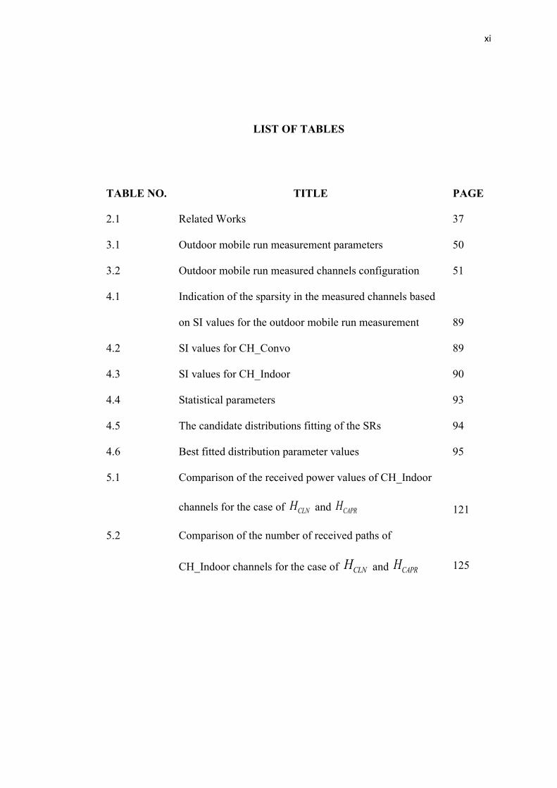
LIST OF TABLES
TABLE NO. TITLE PAGE
2.1 Related Works 37
3.1 Outdoor mobile run measurement parameters 50
3.2 Outdoor mobile run measured channels configuration 51
4.1 Indication of the sparsity in the measured channels based
on SI values for the outdoor mobile run measurement
89
4.2 SI values for CH_Convo 89
4.3 SI values for CH_Indoor 90
4.4 Statistical parameters 93
4.5 The candidate distributions fitting of the SRs 94
4.6 Best fitted distribution parameter values 95
5.1 Comparison of the received power values of CH_Indoor
channels for the case of CLNH and CAPRH
121
5.2 Comparison of the number of received paths of
CH_Indoor channels for the case of CLNH and CAPRH
125

xii
LIST OF FIGURES
FIGURE NO. TITLE PAGE
2.1 An illustration of the multipath propagation 17
2.2 Illustration of the two-path model 20
2.3 The reception of a single transmitted waveform in the
case of two-path model
21
2.4 The received rays in the case of having multiple
number of scatterers in the measurement environment
23
2.5 CIR of a Time varying channel 24
2.6 Scatterers located on the same ellipses leads to the same
delay in the rays’ propagation
26
2.7 An illustration of the geometric elliptical modeling
approach for single scattering
27
2.8 An illustration of a frequency-domain measurement 29
2.9 An illustration of a time-domain measurement 30
3.1 The research methodology flowchart 41
3.2 Channel Measurements Procedure 44
3.3 The measurement system block diagram 45
3.4 PulsON 410 47
3.5 A snapshot of Tx-Rx connection setup with P410 48
3.6 Measurement floor plan 50
3.7 Measurement Environment (a) First side (b) second
side
52
3.8 A snapshot from the outdoor convocation area
measurement environment
53
3.9 Figure 3.9 Representation of the outdoor
convocation area measurement procedure, showing the
Tx and the Rx locations in addition to the surrounding

xiii
scatterers 54
3.10 Floor plan of the indoor office measurement 55
3.11 Indoor office measurement environment 56
3.12 Illustration of finding the correlation coefficient values
between consecutive PDPs
57
3.13 Illustration of the data post processing for the measured
waveform in order to extract the CIRs
59
3.14 A Sample of a received waveform 60
3.15 Template waveform of P410 61
3.16 Measuring the UWB channel in the anechoic chamber 62
3.17 Measured UWB waveform for 1 m distance in the
anechoic chamber
63
3.18 Measured UWB waveform in the anechoic chamber
versus the template waveform
63
3.19 Extracting the CIRs form the measured UWB
waveforms (a) Deconvolution process between the
template waveform and the received pulse (b)
Constructed CIRs based on the deconvolution process
64
3.20 An illustration of the APR and ToAR algorithms
development sequence
66
3.21 Illustration of the development of CAPR algorithm
showing its two phases that are the APR and ToAR
algorithms
68
3.22 Block diagram of APR algorithm procedure 71
3.23 Illustration of the performance evaluation of the
developed algorithm where the comparison is held with
the original single-template CLEAN algorithm as a
benchmark
73
4.1 Outdoor mobile run CIR for CH1_Towards with
normalized magnitudes
78
4.2 Outdoor mobile run CIRs P410 magnitudes (a) CH1-
Towards (b) CH1-Away (c) CH2-Towards (d) CH2-
Away
80

xiv
4.3 A sample from the channel snapshot of CH_Convo at
position 1
82
4.4 Sample channel snapshots of indoor office
measurement (a) position 1 (b) position 2 (c) position 5
(d) position 10
85
4.5 Contour plot of indoor office measurement 86
4.6 Correlation coefficient values between adjacent PDPs
of CH1_Towards
90
4.7 Histogram of the SRs for CH1_Towards 91
4.8 CDFs of the obtained stationarity regions 91
4.9 Exponential distribution fitted to the CDF of the SRs
for CH1_Towards
94
5.1 Contour plots of the CLNH CIRs for (a) CH1-Towards
(b) CH1_Away (c) CH2_Towards (d) CH2_Away 100
5.2 A sample snapshot from CH2_Towards for (a) CLNH
(b) APRH 101
5.3 Sample snapshot from CH_Indoor showing the
received paths versus delay for (a) CLNH (b) APRH
103
5.4 A sample snapshot from the last position (position 10)
of CH_indoor (a) CLNH (b) APRH
105
5.5 Number of elements in the channel snapshot of position
1 from CH_Indoor (a) CLNH (b) APRH 106
5.6 Difference in the ToA of the highlighted path (a) CLNH
(b) APRH 108
5.7 Illustration of the CIRs structuring by the CAPR
algorithm
110
5.8 Number of elements in the channel snapshot of position
1 from CH_Indoor (a) CLNH (b) APRH (c) CAPRH 112
5.9 Difference in the ToA of the highlighted path (a) CLNH
114

xv
(b) APRH (c) CAPRH
5.10 Received power comparison on the measured channels
in the case of CLNH and CAPRH (a) CH1_Towards (b)
CH1_Away (c) CH2_Towards (d) CH2_Away (e)
CH_Convo (f) CH_Indoor 118
5.11 Number of paths available in each channel snapshot as
a function of the distance for (a) CH1_Towards (b)
CH1_Away (c) CH2_Towards (d) CH2_Away (e)
CH_Convo (f) CH_Indoor
123

xvi
LIST OF ABBREVIATIONS
AoA - Angle of arrival
AoE - Angle of elevation
APR - Artifact paths removal
BW - Bandwidth
CAPR - Complete artifact paths removal
CAT - Channel analysis tool
CIR - Channel impulse response
DARPA - Defense Advanced Research Projects
DSO - Digital signal oscilloscope
FCC - Federal Communications Commission
GEV - Generalized Extreme Value
GoF - Goodness of fit
GPS - Global Positioning System
I2V - Infrastructure to vehicle
IEEE - Institute of Electrical and Electronics Engineers
IO - Interlacing object
ITU - International Telecommunication Union
ITU-R - International Telecommunication Union
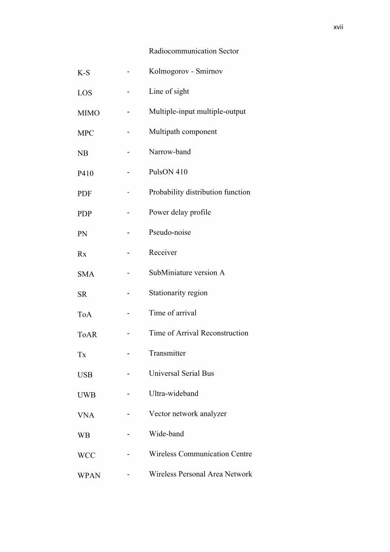
xvii
Radiocommunication Sector
K-S - Kolmogorov - Smirnov
LOS - Line of sight
MIMO - Multiple-input multiple-output
MPC - Multipath component
NB - Narrow-band
P410 - PulsON 410
PDF - Probability distribution function
PDP - Power delay profile
PN - Pseudo-noise
Rx - Receiver
SMA - SubMiniature version A
SR - Stationarity region
ToA - Time of arrival
ToAR - Time of Arrival Reconstruction
Tx - Transmitter
USB - Universal Serial Bus
UWB - Ultra-wideband
VNA - Vector network analyzer
WB - Wide-band
WCC - Wireless Communication Centre
WPAN - Wireless Personal Area Network

xviii
WSN - Wireless Sensor Network
xix
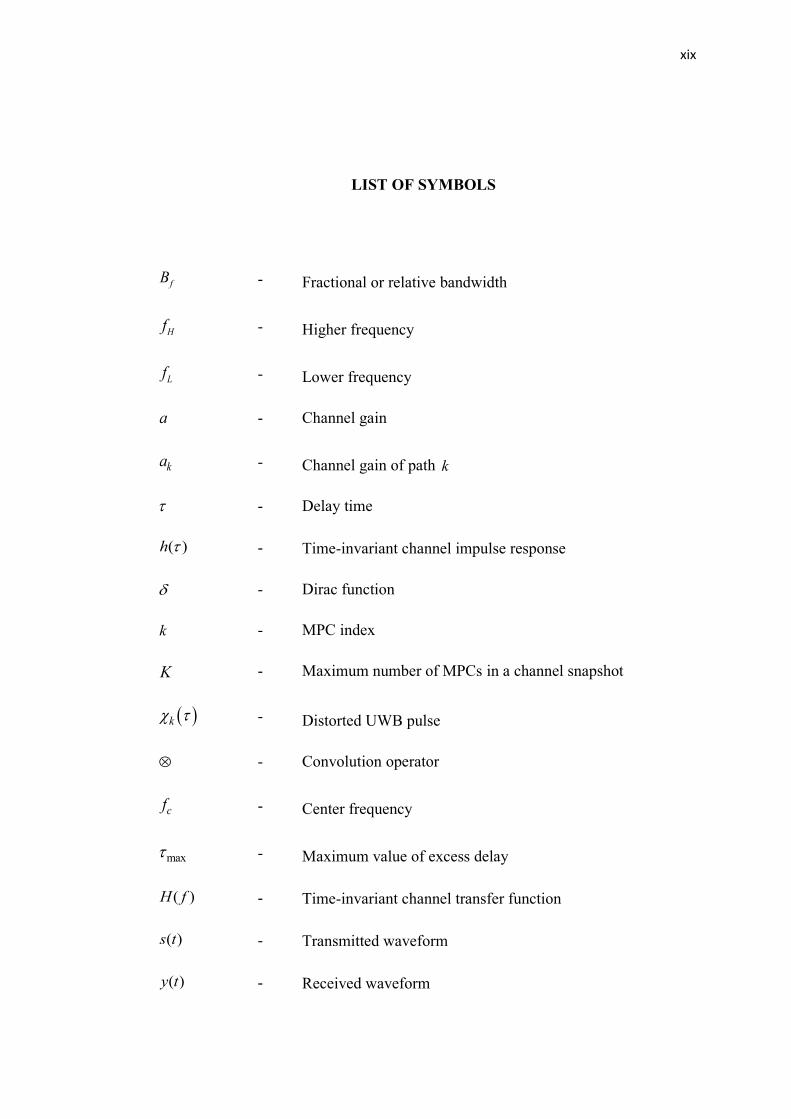
LIST OF SYMBOLS
fB - Fractional or relative bandwidth
Hf - Higher frequency
Lf - Lower frequency
a - Channel gain
ka - Channel gain of path k
- Delay time
( )h - Time-invariant channel impulse response
- Dirac function
k - MPC index
K - Maximum number of MPCs in a channel snapshot
k - Distorted UWB pulse
- Convolution operator
cf - Center frequency
max - Maximum value of excess delay
( )H f - Time-invariant channel transfer function
( )s t - Transmitted waveform
( )y t - Received waveform
xx
( )h t - Channel impulse response of an arbitrary waveform
r - Correlation process
( )ssr t - Auto-correlation
( )syr t - Cross-correlation
1 - Runtime of path 1
1d - Traveling distance of path 1
2 - Runtime of path 2
2d - Traveling distance of path 2
c - Signal propagation speed
d - Duration between the arrival of two UWB pulses
k - Delay time of path k
( , )nh t - Time –varying channel impulse response
n - Channel snapshot index
N - Maximum number of measured channel snapshots
- Ellipse width
,n kh t - Channel response for path k in channel snapshot n
t - Time variation index
nz - Vector of nonzero elements
SI - Sparsity index
SIn - Sparsity index of n th channel snapshot

xxi
( , )nP t - Power delay profile
C - Correlation coefficient
(x,y) - Correlation coefficient between two PDPs
cov(x,y) - Covariance
X - Standard deviation of random variable X
Y - Standard deviation of random variable Y
THC - Correlation threshold value
- Exponential distribution continuous inverse scale parameter
- Weibull distribution shape parameter
- Weibull distribution scale parameter
- GEV distribution shape parameter
- GEV distribution scale parameter
- GEV distribution location parameter
LOSh - Channel response of the LOS path
CLNh - Channel snapshot vector from the measured CIR
CLNH - CIR of Single-template CLEAN
APRH - CIR after using APR algorithm
CAPRH - CIR after using CAPR algorithm

xxii
LIST OF APPENDICES
APPENDIX TITLE PAGE
A List of publications 140
B PulsON 410 properties 142
C Template waveform extraction for PulsON 410 147
D SI values of measured CIRs for the outdoor mobile run
measurement
150
E SI values of measured CIRs for the outdoor convocation
area measurement
154
F SI values of measured CIRs for the indoor office
measurement
155

CHAPTER 1
INTRODUCTION
1.1 Introduction
The wireless communications field represents a big engineering success in the
recent two to three decades. The success is not considered from the scientific view
only, but from the economic and impact on society as well. Many companies that were
not known transferred to be a giant household due to their work on the wireless
communications systems. In addition, several countries are depending on the wireless
communications industry as a main dominant part in their economical budget. By
observing the communications of information in history, wireless communications
show its oldest form. It started simply through shouts or jungle drums that were an
innovative way of communications before civilization eras in order to transmit the
information wirelessly. No cable or wiring was used for this purpose. Smoke signals
were an example of a line of sight (LOS) communication that conveys a certain
message to the receiving partner. However, the wireless communication, as we know,
started with the basis of electromagnetic signals transmission led by Maxwell and
Hertz [1].
The first publicized wireless communication was successfully conducted by
Marconi in 1898. The demonstration was achieved in the English Channel from a boat
to the Isle of Wight. The great achievement of Marconi led him to be recognized as
the inventor of the modern wireless communications. Nobel prize was awarded to him
in 1909 due to this achievement [1]. It is noted that some talks advertise that Tesla
was the first successful person in achieving the first wireless communications system

2
by demonstrating the transmission of the information through electromagnetic waves,
but the stronger public relations of Maroni led him to be regarded as the inventor of
the wireless communications system [1]. The utilization of radio communications (one
direction) spread out throughout the whole world in the following years. A wide
network of transmission of information wirelessly was available by the late 1930s.
Wireless communications advanced by the following decades, as the necessity
for having a high data rate communication was available for the transmission of audio
and video signals. In this case, the idea of using signals of high bandwidth in the
wireless communication systems started, where ultra-wideband (UWB) signals were a
proposed option for this requirement, and the pioneering contribution in the field of
UWB communications was achieved by Bennett and Ross in 1978 [2] and Harmuth in
1981 [3]. A huge frequency band can be made from the UWB system that it ranges
from 3.1 – 10.6 GHz [4]. This high bandwidth leads to high data rate communication
according to what Shannon illustrated in his work [5].
In order to have a successful communication system, there are several
parameters that need to be studied and modeled accurately. One of these parameters
is the wireless channel. Indeed, the performance of the wireless communication
system depends on the propagation condition between two entities that are the
transmitter (Tx) and the receiver (Rx) where the channel represents the medium
between them [6]. As the propagation channel is an important part in any
communication system where it represents the environment in which the signal travels
from the Tx to the Rx, understanding the behavior of the communication system
channel is needed. The transmitting and receiving devices need to make an agreement
with the channel characteristics where the devices are operated to provide the ultimate
outcome. As a result, a prerequisite part of the UWB system design is the
understanding of the UWB propagation channel.
As the signal is transmitted through the channel to the receiving side, several
scatterers are available which comprise the scattering environment of the particular
channel. The scatterers represent the interlacing objects (IOs) available in the channel
between the transmitting and the receiving sides. Due to the availability of the
3
different scatterers in the channel, multipath components are generated due to the
reflection, diffraction or scattering of the propagated signal with the available
scatterers.
Knowing the scattering environment is important for accurate channel
modeling and characterization. As the number of multi-paths can be approximated to
be the same number of scatterers (considering a single scattering case), determining
the real number of scatterers is crucial for knowing a particular channel behavior.
Based on that, determining the accurate channel behavior in terms of its scattering
environment is needed for accurate communication system design. This can be
achieved for different communication channels, where UWB channel is part of them.
As the case of any communication system, the wireless channel (or simply
referred as the channel) is a main part in determining the performance limit of wireless
communication systems [7]. This case is applicable in any practical case, where the
testing, design and improvement of the system depends on understanding the channel
that signals propagate through. In order to achieve this purpose, channel
measurements are needed in order to study its effect on the propagated signals.
Channel measurements are valuable in studying different channel
characteristics. The channel impulse response (CIR) is extracted from the received
measured waveform obtained during the channel measurement campaign. From the
CIR, different channel parameters are extracted representing the different
characteristics such as power, delay spread, and frequency dispersion. The obtained
parameters from the measurements are beneficial in studying and modeling the
channel small scale and large scale characteristics.
In the case of UWB channel measurements, CLEAN algorithm is used in order
to extract the CIRs from the measured UWB waveforms. In CLEAN, the data are
processed by comparing the measurement information (dirty map) with a priori
information (template). Then the resulted CIRs , representing the clean map, are
reconstructed based on cancelling the detected similarities [8]. However, the extracted
CIRs usually contain artifact paths. These artifact paths are registered as channel

4
response values representing a reflected signal from a scatterer. In reality, these paths
do not represent a real scattering environment and this affects accurate channel
behavior [8], [9]. Therefore, removing the artifact paths is important to conserve better
and more realistic scattering environment which results in more accurate channel
characterization and modeling.
In the literature, some approaches are available in developing the CLEAN
algorithm through the removal of the artifact paths and getting better scattering
environment. The approaches focused on using multi-template CLEAN algorithm
instead of the single-template one. In the multi-template CLEAN, the deconvolution
between the received waveform and the template is done with several UWB template
waveforms instead of a single one in the single-template case. These cases are seen in
[8], [10], [11]. The proposed template waveforms are extracted from channel
measurements in particular environments. If the CIRs need to be extracted for other
measurement environments, the template waveform should be found from that specific
environment. The template that is not proper for the deconvolution process may
decrease the algorithm performance [12]. In this case, developing an approach that
enhances the obtained outcome of the single-template CLEAN algorithm is beneficial
for the general utilization in any environment with the same original undistorted
template waveform.
1.2 Problem Statement
UWB channel measurement is conducted in order to study the channel
behavior in a particular environment. The CIRs are extracted from the measured UWB
waveforms through the utilization of the CLEAN algorithm. The method is based on
a deconvolution process between the received UWB waveforms and a template
waveform. The resulted CIRs contain artifact paths that do not represent real multipath
components (MPCs) and are generated during the deconvolution process. Therefore,
removing these artifact paths is needed to get more accurate scattering environment
and, as a result, more accurate channel is observed. Previous researches focused on
the idea of using multi-template CLEAN to decrease the effect of artifact paths.

5
However, this method contains the challenges of the need of getting the UWB template
waveforms from the measured environments [8], [10]–[12]. In addition, if the selected
template accuracy is low, the extracted CIRs accuracy will decrease [12].
In order to address the main research problem given above, answers to several
questions need to be provided as a prerequisite.
1. What is the importance and the aim of this study?
2. What is the theoretical framework that can be used to develop an
algorithm to remove such artifact paths?
3. How to do the UWB channel measurements, and what are the
measurement techniques and devices that can be used?
4. How to validate the research?
5. What are the consequences of the application of the algorithm on the
channel behavior?
1.3 Research Aim and Objectives
The aim of this study is to obtain accurate channel behavior based on cleaning
the measured UWB CIRs from any artifact paths. The results in removing artifact
paths are important for modeling specific statistics [13] where accurate number of
paths is crucial. Extracting more accurate CIRs that represent the real scattering
environment results in better channel characterization and modeling. In the final
outcome, better UWB communication system performance is achieved.
In the purpose of providing the possible solutions to the presented problem
statement, the objectives of this research are as follows:

6
To measure and study the UWB channel through conducting outdoor
and indoor measurement campaigns.
To extract measured CIRs using the single-template CLEAN algorithm.
To develop an algorithm to remove the artifact paths in addition to
analyzing and evaluating the performance of the proposed algorithm.
1.4 Scope of Research
The scope of this research can be seen in the following points:
The algorithm is developed based on the theory of elliptical modeling where
the wideband channel comprised of several delay taps.
The algorithm is used after the CIRs extraction by the single-template
CLEAN algorithm.
UWB channel measurements are based on Time-Domain technique.
The equipment used in the measurements is PulsON 410 which is a UWB
radio transceiver.
The frequency range of the UWB measurement is 3.1 – 5.3 GHz.
The transmitted UWB pulse bandwidth is 2.2 GHz, and the center frequency
is 4.3 GHz.
The transmission power from PulsON 410 is -14.3 dBm.
7
Channel measurements are based on single-input single-output (SISO)
scheme, where two antennas are used in the measurement, one at the
transmitting side and the other at the receiving side.
MATLAB® software is used for simulation results and analysis.
The UWB channel measurements are conducted in outdoor and indoor
environments.
The conducted measurements have LOS communication.
1.5 Research Contributions
This research contributes to the huge field of UWB communications in terms
of the UWB channel part. The contribution goes to provide more accurate CIRs
through clearing the measured CIRs (single-template CLEAN CIRs) from any artifact
paths generated due to the utilization of the single-template CLEAN algorithm. The
contributions of this thesis are shown in the following subsections
1.5.1 Removal of the Artifact Paths from the Measured CIRs
The main contribution of this thesis is the development of an algorithm that
removes the artifact paths from the measured CIRs. The algorithm represents an
enhancement to the CLEAN algorithm and will be run after getting the CIRs by
CLEAN. Thus, it can be used to structure the data after the CLEAN algorithm and get
CIRs which are more practical and more likely to be empty from artifact (or phantom)
paths.
Two main phases have been developed in this algorithm: Firstly, the
development of the algorithm based on the theory of the elliptical modeling has been
8
programmed. In this stage, the removal of the artifact paths is the main purpose of this
algorithm. Secondly, In order to restore accurate time of arrivals (ToAs) of the
received paths, phase 2 has been added, where another algorithm is developed for this
purpose. Based on that, the real channel values with their accurate ToAs have been
preserved and any path that does not agree with the elliptical modeling theory has been
removed. Notice that the paths removal does not affect the real channel behavior as
this removal agrees with practical cases stated in the literature.
1.5.2 Sparse Indoor and Outdoor UWB Channel Measurements
In order to understand and study the behavior of the UWB channel, several
measurements have been conducted. The measured data enhances the knowledge of
the channel and is needed for the development of the algorithms. The measurements
were conducted in outdoor and indoor environments in order to have full insight on
the difference in the measured CIRs that is caused due to the measurement
environment.
1.5.3 Stationarity Regions for UWB Channels
The stationarity regions of the UWB channel have been extracted based on the
correlation between the power delay profiles (PDPs) of the measured channel
snapshots (one channel snapshot represents one measured UWB pulse with its received
multi-paths). The regions are studied based on the conducted measurement of the
mobile run scheme and the statistical analysis has been achieved. The knowledge of
the stationarity regions assists in defining the distance steps where the channel has
significance variation.

9
1.5.4 Channel Sparsity Determination using the Sparsity Index
The sparsity index has been defined as the number of non-zero elements in the
channel snapshots registered during the measurements. The analysis of the sparsity of
each channel is done by focusing on this parameter. In addition, it has been used in
order to calculate the received power of the channel in this type of sparsity behavior.
1.6 Thesis Outline
The thesis consists of six chapters. The outline of the remaining chapters is
presented in this section.
In Chapter 2, the literature review of the work is illustrated. It starts from the
explanation on the theory of the UWB communication. The UWB channel is then
illustrated in terms of the theory. The different channel measurement techniques are
elaborated along with the theory of the CLEAN algorithm and the CIR extraction.
Finally, the chapter goes to the related works in this field.
In Chapter 3, the methodology that has been used to achieve the research
objectives is described. The chapter starts with the method of conducting channel
measurements in terms of the used equipment and the selected environment. Then the
method of algorithm development is presented.
In Chapter 4, the measurement campaigns that have been conducted in this
research are elaborated. Studying the channel behavior in detail has been achieved in
terms of the effect of the different measurement environments. In order to understand
the UWB channel characteristics in terms of the measured CIRs in the measurement
environments, indoor and outdoor measurements are conducted. The chapter contains
also the sparsity analysis of the UWB channel. The sparsity index is defined and used
for this purpose. More details about the organization of this chapter and the reason for
its sections hierarchy is shown in the Introduction section of the chapter.

10
In Chapter 5, the results of the developed algorithm is presented. A comparison
is shown between the results of the developed algorithm with the results of the single-
template CLEAN algorithm. In addition, the effect of applying the developed
algorithm on single-template CLEAN CIRs is shown in terms of the received power
and the number of received paths.
In Chapter 6, the conclusion of the conducted research is contained, where the
main points of the research are restated in addition to elaborating the research findings.
An illustration of the objectives achievements has been included. The limitations and
challenges that are encountered in this research are presented. Finally, main points
of the future work that can be conducted based on the lessons that are learned and
understood from the research shown in this thesis have been included.
131
enhanced the power extracted from the CIRs, which is good for better Signal to Noise
(SNR) values. The number of received paths shows the spread of the channel, where
this research made enhancement in decreasing the number of paths due to the removal
of any possible artifact paths. In this regard, other metrics can be evaluated in the
future, such as the RMS delay spread to check how the difference of the number of
paths affected this metric, the possible decrement of the RMS delay spread will be
beneficial in getting better coherence bandwidth values, where the two metrics are
inversely proportional.

132
REFERENCES
1. Molisch, A. F. A., Wireless communications, 2nd. ed. John Wiley & Sons Ltd.,
2011.
2. Bennett, C. L. and Ross, G. F., TIME-DOMAIN ELECTROMAGNETICS
AND ITS APPLICATIONS., Proceedings of the IEEE, 66(3):. 299–318, 1978.
3. Harmuth, H. F., Nonsinusoidal waves for radar and radio communication, 1981.
4. Kaiser, T. and Zheng, F., ULTRA WIDEBAND SYSTEMS WITH MIMO. John
Wiley & Sons Ltd., 2010.
5. Shannon, C. E., A mathematical theory of communication, Bell Syst. Tech. J.,
27, 1948.
6. Pagani, P., Talom, F. T., Pajusco, P., and Uguen, B., Ultra-Wideband Radio
Propagation Channels, First Edit. John Wiley & Sons, Inc., 2008.
7. Molisch, A. F., Ultra-wide-band propagation channels, Proc. IEEE, 97(2):,
353–371, 2009.
8. Liu, T., Kim, D., and Vaughan, R., A high-resolution, multi-template
deconvolution algorithm for time-domain UWB channel characterization, Can.
J. Electr. Comput. Eng., 32(4):, 207–213, 2007.
9. Molisch, A. F., Ultrawideband Propagation Channels-Theory, Measurement,
and Modeling, IEEE Trans. Veh. Technol., 54(5):, 1528–1545, Sep. 2005.
10. Muqaibel, A., Safaai-Jazi, A., Woerner, B., and Riad, S., UWB channel impulse
response characterization using deconvolution techniques, in The 2002 45th
Midwest Symposium on Circuits and Systems, 2002. MWSCAS-2002., 3, III–
605–8.
11. Yang, W. and Naitong, Z., A New Multi-Template CLEAN Algorithm for
UWB Channel Impulse Response Characterization, in 2006 International
Conference on Communication Technology, 2006, 1–4.
12. Li, D., Zhou, Z., Li, B., and Zou, W., A multi-template deconvolution algorithm
based on compressed sensing for UWB channel modeling, in 2011 6th
International ICST Conference on Communications and Networking in China
(CHINACOM), 2011, 974–978.
13. Donlan, B. M., McKinstry, D. R., and Buehre, R. M., The UWB indoor channel:
large and small scale modeling, IEEE Trans. Wirel. Commun., 5(10):, 2863–
2873, Oct. 2006.
14. Benedetto, M.-G. Di, Kaiser, T., Molisch, A. F., Opperman, I., Politano, C., and
Porcino, D., UWB communication systems: a comprehensive overview.
Hindawi Publishing Corporation, 2006.
15. FCC, FCC press release, 2002. [Online]. Available:
https://transition.fcc.gov/Bureaus/Engineering_Technology/News_Releases/2
002/nret0203.html.
133
16. FCC, First Report and Order in The Matter of Re- vision of Part 15 of the
Commission’s Rules Regarding Ultrawideband Transmission Systems , ET-
Docket 98-153, FCC 02-48, 2002.
17. Taylor, J., Introduction to ultra-wideband radar systems. CRC press, 1994.
18. ITU-R SM.1754, Measurement techniques of ultra-wideband transmissions,
2006.
19. ITU-R SM.1755, Characteristics of ultra-wideband technology, 2006.
20. ITU R SM.1756, Framework for the introduction of devices using ultra-
wideband technology, 2006.
21. ITU-R SM.1757, Impact of devices using ultra-wideband technology on
systems operating within radiocommunication services, 2006.
22. Molisch, A. F., Balakrishnan, K., Chong, C., Emami, S., Fort, A., Karedal, J.,
Kunisch, J., Schantz, H., Schuster, U., and Siwiak, K., IEEE 802.15. 4a channel
model-final report, 2004.
23. IEEE 802 Study Groups Status. [Online]. Available:
http://www.ieee802.org/StudyGroups.shtml.
24. Win, M. Z., Dardari, D., Molisch, A. F., and Wiesbeck, W., History and
Applications of UWB [Scanning the Issue], Proc. IEEE, 97(2):, 198–204, Feb.
2009.
25. Siriwongpairat, W. P. and Liu, K. J. R., Ultra-wideband communications
systems: multiband OFDM approach. New Jersey: John Wiley & Sons, 2007.
26. Catherwood, P. A. and Scanlon, W. G., Ultrawideband Communications—An
Idea Whose Time has Still Yet to Come?, IEEE Antennas Propag. Mag., 57(2):,
38–43, Apr. 2015.
27. Xiong, H. and Cheng, J., Investigation of short-range high precision 3D
localization via UWB radio, in 2014 IEEE Global Communications Conference,
2014, 4090–4095.
28. Gezici, S., Tian, Z., Giannakis, G. B., Kobayashi, H., Molisch, A. F., Poor, H.
V., and Sahinoglu, Z., Localization via ultra-wideband radios: A look at
positioning aspects of future sensor networks, IEEE Signal Process. Mag.,
22(4):, 70–84, 2005.
29. Reghunath, V. and M.N., U. R., Band Notched UWB Antenna for Wireless
Body Area Network, 2014 Fourth Int. Conf. Adv. Comput. Commun., (1):, 305–
308, 2014.
30. Allen, B., Ghavami, M., Armogida, A., and Aghvami, H., The holy grail of wire
replacement, Commun. Eng., 1(5):, 14–17, 2003.
31. Thotahewa, K. M. S., Khan, J. Y., and Yuce, M. R., Power Efficient Ultra Wide
Band Based Wireless Body Area Networks with Narrowband Feedback Path,
IEEE Trans. Mob. Comput., 13(8):, 1829–1842, Aug. 2014.
32. Smith, D. B., Miniutti, D., Lamahewa, T. A., and Hanlen, L. W., Propagation
Models for Body-Area Networks: A Survey and New Outlook, IEEE Antennas
Propag. Mag., 55(5):, 97–117, Oct. 2013.
33. Hamalainen, M., Taparugssanagorn, A., Tesi, R., and Iinatti, J., Wireless
medical communications using UWB, in 2009 IEEE International Conference
on Ultra-Wideband, 2009, 485–489.
134
34. Thotahewa, K. M. S., Redoute, J.-M., and Yuce, M. R., A Low-Power Wearable
Dual-Band Wireless Body Area Network System: Development and
Experimental Evaluation, IEEE Trans. Microw. Theory Tech., 62(11):, 2802–
2811, Nov. 2014.
35. Rout, D. K. and Das, S., Multiple narrowband interference mitigation in UWB
body area networks for body surface communications, in 2014 International
Conference on Medical Imaging, m-Health and Emerging Communication
Systems (MedCom), 2014, 184–188.
36. Khaleghi, A., Chavez-Santiago, R., Liang, X., Balasingham, I., Leung, V. C.
M., and Ramstad, T. A., On ultra wideband channel modeling for in-body
communications, in IEEE 5th International Symposium on Wireless Pervasive
Computing 2010, 2010, 140–145.
37. Khaleghi, A., Chavez-Santiago, R., and Balasingham, I., An improved ultra
wideband channel model including the frequency-dependent attenuation for in-
body communications, in 2012 Annual International Conference of the IEEE
Engineering in Medicine and Biology Society, 2012, 1631–1634.
38. Zahner, M., Wang, J., and Frohlich, J., Benefits and limits of UWB for In- and
out-of-body communication, in 2014 XXXIth URSI General Assembly and
Scientific Symposium (URSI GASS), 2014, 1–4.
39. Stoa, S., Chavez-Santiago, R., and Balasingham, I., An ultra wideband
communication channel model for the human abdominal region, in 2010 IEEE
Globecom Workshops, 2010, 246–250.
40. Khaleghi, A., Chávez-Santiago, R., and Balasingham, I., Ultra-wideband
statistical propagation channel model for implant sensors in the human chest,
IET Microwaves, Antennas Propag., 5(15):, 1805, 2011.
41. Ibraheem, A. and Manteghi, M., Path Loss inside human body using Electrically
Coupled Loop Antenna at different frequency bands, in 2014 IEEE Antennas
and Propagation Society International Symposium (APSURSI), 2014, 977–978.
42. Kumpuniemi, T., Hamalainen, M., Yazdandoost, K. Y., and Iinatti, J., Dynamic
on-body UWB radio channel modeling, in 2015 9th International Symposium
on Medical Information and Communication Technology (ISMICT), 2015, 126–
130.
43. Kumpuniemi, T., Hamalainen, M., Tuovinen, T., Yazdandoost, K. Y., and
Iinatti, J., Radio channel modelling for pseudo-dynamic WBAN on-body UWB
links, in 2014 8th International Symposium on Medical Information and
Communication Technology (ISMICT), 2014, 1–5.
44. Floor, P.-A., Chavez-Santiago, R., Brovoll, S., Aardal, O., Bergsland, J.,
Grymyr, O.-J., Halvorsen, P. S., Palomar, R., Plettemeier, D., Hamran, S.-E.,
Ramstad, T., and Balasingham, I., In-Body to On-Body Ultra Wideband
Propagation Model Derived from Measurements in Living Animals, IEEE J.
Biomed. Heal. Informatics, 1–1, 2015.
45. Santos, T., Karedal, J., Almers, P., Tufvesson, F., and Molisch, A., Modeling
the ultra-wideband outdoor channel: Measurements and parameter extraction
method, IEEE Trans. Wirel. Commun., 9(1):, 282–290, Jan. 2010.
46. Goodman, D. J., Borras, J., Mandayam, N. B., and Yates, R. D.,
INFOSTATIONS: a new system model for data and messaging services, in
1997 IEEE 47th Vehicular Technology Conference. Technology in Motion,

135
1997, 2, 969–973.
47. Small, T. and Haas, Z. J., The shared wireless infostation model, in Proceedings
of the 4th ACM international symposium on Mobile ad hoc networking &
computing - MobiHoc ’03, 2003, 233.
48. Rajappan, G., Acharya, J., Liu, H., Mandayam, N., Seskar, I., and Yates, R.,
Mobile Infostation Network Technology, in Defense and Security Symposium.
International Society for Optics and Photonics, 2006, 62480M–62480M–9.
49. Richardson, P., Xiang, W., and Shan, D., UWB outdoor channel environments:
analysis of experimental data collection and comparison to IEEE 802.l5.4a
UWB channel model, Int. J. Ultra Wideband Commun. Syst., 3, 1–7, 2014.
50. Mahf, M. R., Fathy, A. E., Kuhn, M. J., and Wang, Y., Recent trends and
advances in UWB positioning, in 2009 IEEE MTT-S International Microwave
Workshop on Wireless Sensing, Local Positioning, and RFID, 2009, 1–4.
51. Anderson, C. R., Volos, H. I., and Buehrer, R. M., Characterization of Low-
Antenna Ultrawideband Propagation in a Forest Environment, IEEE Trans.
Veh. Technol., 62(7):, 2878–2895, Sep. 2013.
52. Demir, U., Bas, C. U., and Coleri Ergen, S., Engine Compartment UWB
Channel Model for Intravehicular Wireless Sensor Networks, IEEE Trans. Veh.
Technol., 63(6):, 2497–2505, Jul. 2014.
53. Bas, C. U. and Ergen, S. C., Ultra-wideband Channel Model for Intra-vehicular
Wireless Sensor Networks Beneath the Chassis: From Statistical Model to
Simulations, IEEE Trans. Veh. Technol., 62(1):, 14–25, Jan. 2013.
54. Herrmann, R. and Sachs, J., M-sequence-based ultra-wideband sensor network
for vitality monitoring of elders at home, IET Radar, Sonar Navig., 9(2):, 125–
137, Feb. 2015.
55. Alereon High-Speed Wireless Solutions. [Online]. Available:
http://www.alereon.com/?page_id=2959.
56. Degli-Esposti, V., Guiducci, D., De’Marsi, A., Azzi, P., and Fuschini, F., An
advanced field prediction model including diffuse scattering, IEEE Trans.
Antennas Propag., 52(7):, 1717–1728, Jul. 2004.
57. Richter, A. and Thoma, R. S., Joint Maximum Likelihood Estimation of
Specular Paths and Distributed Diffuse Scattering, in 2005 IEEE 61st Vehicular
Technology Conference, 1, 11–15.
58. Fugen, T., Maurer, J., Kayser, T., and Wiesbeck, W., Verification of 3D Ray-
tracing with Non-Directional and Directional Measurements in Urban
Macrocellular Environments, in 2006 IEEE 63rd Vehicular Technology
Conference, 6, 2661–2665.
59. Ray-Rong Lao, Jenn-Hwan Tarng, and Chiuder Hsiao, Transmission
coefficients measurement of building materials for UWB systems in 3 -10 GHz,
in The 57th IEEE Semiannual Vehicular Technology Conference, 2003. VTC
2003-Spring., 1, 11–14.
60. Parsons, J. D. and Bajwa, A. S., Wideband characterisation of fading mobile
radio channels, Commun. Radar Signal Process. IEE Proc. F, 129(2):, 95, 1982.
61. Costa, N. and Haykin, S., MULTIPLE-INPUT,MULTIPLE-OUTPUT
CHANNEL MODELS Theory and Practice. John Wiley & Sons, Inc., 2010.
62. Ghassemzadeh, S. S., Jana, R., Rice, C. W., Turin, W., and Tarokh, V.,
136
Measurement and Modeling of an Ultra-Wide Bandwidth Indoor Channel,
IEEE Trans. Commun., 52(10):, 1786–1796, Oct. 2004.
63. Noori, N., Karimzadeh-baee, R., and Abolghasemi, A., An Empirical Ultra
Wideband Channel Model for Indoor Laboratory Environments,
Radioengineering, 18, 68–74, 2009.
64. Chong, C., Kim, Y., and Lee, S., Statistical characterization of the uwb
propagation channel in various types of high-rise apartments, in IEEE Wireless
Communications and Networking Conference, 2005, 2005, 2, 944–949.
65. Cramer, R. J.-M., Scholtz, R. A., and Win, M. Z., Evaluation of an ultra-wide-
band propagation channel, IEEE Trans. Antennas Propag., 50(5):, 561–570,
May 2002.
66. Lee, J., UWB Channel Modeling in Roadway and Indoor Parking
Environments, IEEE Trans. Veh. Technol., 59(7):, 3171–3180, Sep. 2010.
67. Win, M. Z., Scholtz, R. a., and Barnes, M. a., Ultra-wide bandwidth signal
propagation for indoor wireless communications, in Proceedings of ICC’97 -
International Conference on Communications, 1997, 1, 56–60.
68. Jemai, J., Piesiewicz, R., Geise, R., Schmidt, I., Schwark, M., Schirrmacher,
M., and Kurner, T., UWB channel modeling within an aircraft cabin, 2008 IEEE
Int. Conf. Ultra-Wideband, 2, 5–8, Sep. 2008.
69. Di Francesco, A., Di Renzo, M., Feliziani, M., Graziosi, F., Manzi, G., Santucci,
F., Minutolo, R., and Presaghi, R., Sounding and modelling of the ultra wide-
band channel in outdoor scenarios, in 2nd International Workshop Networking
with Ultra Wide Band and Workshop on Ultra Wide Band for Sensor Networks,
2005. Networking with UWB 2005., 2005, 20–24.
70. Kim, C. W., Sun, X., Chiam, L. C., Kannan, B., Chin, F. P. S., and Garg, H. K.,
Characterization of ultra-wideband channels for outdoor office environment, in
IEEE Wireless Communications and Networking Conference, 2005, 2005,
2(C):, 950–955.
71. Souza, C. F. and Bello, J. C. R. D., UWB Signals Transmission in Outdoor
Environments for Emergency Communications, in 2008 11th IEEE
International Conference on Computational Science and Engineering -
Workshops, 2008, 343–348.
72. Santos, T., Ultra-Wideband Wireless Channels – Estimation , Modeling and
Material Characterization, Lund University, 2009.
73. Molisch, A. F., Foerster, J. R., and Pendergrass, M., Channel models for
ultrawideband personal area networks, IEEE Wirel. Commun., 10(6):, 14–21,
Dec. 2003.
74. Cassioli, D., Win, M. Z., and Molisch, A. F., The ultra-wide bandwidth indoor
channel: from statistical model to simulations, IEEE J. Sel. Areas Commun.,
20(6):, 1247–1257, Aug. 2002.
75. Cassioli, D. and Durantini, a., A time-domain propagation model of the UWB
indoor channel in the FCC-compliant band 3.6 - 6 GHz based on PN-sequence
channel measurements, 2004 IEEE 59th Veh. Technol. Conf. VTC 2004-Spring
(IEEE Cat. No.04CH37514), 1, 213–217, 2004.
76. Schuster, U. G. and Bölcskei, H., Ultrawideband channel modeling on the basis
of information-theoretic criteria, IEEE Trans. Wirel. Commun., 6(7):, 2464–

137
2474, 2007.
77. Yano, S. M., Investigating the ultra-wideband indoor wireless channel, Veh.
Technol. Conf. IEEE 55th Veh. Technol. Conf. VTC Spring 2002 (Cat.
No.02CH37367), 3, 1200–1204, 2002.
78. Vaughan, R. G. and Scott, N. L., Super-resolution of pulsed multipath channels
for delay spread characterization, IEEE Trans. Commun., 47(3):, 343–347, Mar.
1999.
79. Liang, J., Liang, Q., and Member, S., Outdoor Propagation Channel Modeling
in Foliage Environment, IEEE Trans. Veh. Technol., 59(5):, 2243–2252, 2010.
80. Högbom, J. A., Aperture Synthesis with a Non-Regular Distribution of
Interferometer Baselines, Astron. Astrophys. Suppl., 15, 417, 1974.
81. Scholtz, R. a., Cramer, R. J.-M., and Win, M. Z., Evaluation of the propagation
characteristics of ultra-widebandcommunication channels, IEEE Antennas
Propag. Soc. Int. Symp. 1998 Dig. Antennas Gateways to Glob. Network. Held
conjunction with Usn. Natl. Radio Sci. Meet. (Cat. No.98CH36, 2, 626–630,
1998.
82. Siwiak, K., Bertoni, H., and Yano, S. M., Relation between multipath and wave
propagation attenuation, Electron. Lett., 39(10):, 142, 2003.
83. Pendergrass, M. and Beeler, W. C., Empirically Based Statistical Ultra-
Wideband ( UWB ) Channel Model, IEEE P802.15 Work. Gr. Wirel. Pers. Area
Networks, (July):, 2002.
84. Richardson, P. C. and Stark, W., Modeling of ultra-wideband channels within
vehicles, IEEE J. Sel. Areas Commun., 24(4):, 906–912, Apr. 2006.
85. Irahhauten, Z., Janssen, G., Nikookar, H., Yarovoy, A., and Ligthart, L., UWB
Channel Measurements and Results for Office and Industrial Environments, in
2006 IEEE International Conference on Ultra-Wideband, 2006, 225–230.
86. Chang, S. C. S. and Scholtz, R. A., Polarization measurements in a UWB
multipath channel, in IEEE MILCOM 2004. Military Communications
Conference, 2004., 2004, 1, 192–196.
87. Bories, S., Sibille, A., and Roblin, C., UWB indoor channel measurements
study, Proc. - 2005 IEEE Int. Work. Antenna Technol. Small Antennas Nov.
Metamaterials, IWAT 2005, 2005, 466–469, 2005.
88. Liang, Q. L. Q. and Cheng, X. C. X., Wireless channel modeling in foliage
environment: UWB versus narrowband, MILCOM 2008 - 2008 IEEE Mil.
Commun. Conf., 2008.
89. Liang, Q., Radar Sensor Wireless Channel Modeling in Foliage Environment:
UWB Versus Narrowband, IEEE Sens. J., 11(6):, 1448–1457, Jun. 2011.
90. Malik, W. Q. and Molisch, A. F., Ultrawideband antenna arrays and directional
propagation channels, in Proc. Europe Conf. Antennas Propagation (EuCAP),
2006.
91. Makaratat, K. and Stavrou, S., Spatial correlation technique for UWB antenna
arrays, Electron. Lett., 42(12):, 675, 2006.
92. Lee, J. Y. and Scholtz, R. a., Ranging in a dense multipath environment using
an UWB radio link, IEEE J. Sel. Areas Commun., 20(9):, 1677–1683, 2002.
93. Cramer, J. M., Scholtz, R. a., and Win, M. Z., On the analysis of UWB

138
communication channels, MILCOM 1999. IEEE Mil. Commun. Conf. Proc.
(Cat. No.99CH36341), 2, 1191–1195, 1999.
94. Buccella, C., Feliziani, M., and Manzi, G., Detection and localization of defects
in shielded cables by time-domain measurements with UWB pulse injection and
clean algorithm postprocessing, IEEE Trans. Electromagn. Compat., 46(4):,
597–605, 2004.
95. Di Renzo, M., Buehrer, R. M., and Torres, J., Pulse Shape Distortion and
Ranging Accuracy in UWB-Based Body Area Networks for Full-Body Motion
Capture and Gait Analysis, in IEEE GLOBECOM 2007-2007 IEEE Global
Telecommunications Conference, 2007, 3775–3780.
96. Yang, W., Naitong, Z., and Hongbo, Z., A Statistical Model for UWB Non-line-
of-sight Indoor Environment, in 2006 International Symposium on Antennas
and Propagation, 2006, 1–5.
97. Chen, Y. C. Y., Teo, J. T. J., Lai, J. C. Y., Gunawan, E., Low, K. S. L. K. S.,
Soh, C. B. S. C. B., and Rapajic, P. B., Cooperative Communications in Ultra-
Wideband Wireless Body Area Networks: Channel Modeling and System
Diversity Analysis, IEEE J. Sel. Areas Commun., 27(1):, 5–16, 2009.
98. Vaughan, R. G. and Scott, N. L., Super-resolution of pulsed multipath channels
for delay spread characterization, in Proceedings of PIMRC ’96 - 7th
International Symposium on Personal, Indoor, and Mobile Communications,
1996, 3(3):, 781–785.
99. Zhang, P., Hu, Z., Qiu, R. C., and Sadler, B. M., A compressed sensing based
ultra-wideband communication system, IEEE Int. Conf. Commun., 2009.
100. Chandra, A., Blumenstein, J., Mikulasek, T., Vychodil, J., Pospisil, M.,
Marsalek, R., Prokes, A., Zemen, T., and Mecklenbrauker, C., CLEAN
Algorithms for Intra-vehicular Time-domain UWB Channel Sounding, in Proc.
PECCS. Angers, 2015, 224–229.
101. Domain, T., Data Sheet PulsON® 410, 2012.
102. Ispas, A., Schneider, C., Ascheid, G., and Thomä, R., Analysis of the Local
Quasi-Stationarity of Measured Dual-Polarized MIMO Channels, IEEE Trans.
Veh. Technol., 9545(c):, 1–1, 2014.
103. Gehring, A., Steinbauer, M., Gaspard, I., and Grigat, M., Empirical channel
stationarity in urban environments, in Proc. Eur. Personal Mobile
Communications Conf. (EPMCC), 2001.
104. Montgomery, D., Applied Statistics and Probability for Engineers 6th edition.
John Wiley & Sons, 2013.
105. Renzo, M. Di, Graziosi, F., Minutolo, R., Montanari, M., and Santucci, F., The
ultra-wide bandwidth outdoor channel: From measurement campaign to
statistical modelling, Mob. Networks Appl., 11(4):, 451–467, May 2006.
106. Dewberry, B. and Beeler, W., Increased ranging capacity using Ultrawideband
direct-path pulse signal strength with dynamic recalibration, Proc. 2012
IEEE/ION Position, Locat. Navig. Symp., 1013–1017, Apr. 2012.
107. Di Renzo, M., Feliziani, M., Graziosi, F., Manzi, G., and Santucci, F.,
Characterization of the Ultra-Wide Band Channel, in IEEE/ACES International
Conference on Wireless Communications and Applied Computational
Electromagnetics, 2005., 2005, 27–30.
139
108. Renaudin, O., Kolmonen, V.-M., Vainikainen, P., and Oestges, C., Non-
Stationary Narrowband MIMO Inter-Vehicle Channel Characterization in the
5-GHz Band, IEEE Trans. Veh. Technol., 59(4):, 2007–2015, May 2010.
109. Massey, F. J. J., The Kolmogorov-Smirnov test of goodness of fit, J. Am. Stat.
Assoc., 46, 68–78, 1951.
110. Piersanti, S., Annoni, L. A., and Cassioli, D., Millimeter waves channel
measurements and path loss models, 2012 IEEE Int. Conf. Commun., 4552–
4556, Jun. 2012.
111. Cassioli, D., 60 GHz UWB channel measurement and model, in 2012 IEEE
International Conference on Ultra-Wideband, 2012, 145–149.
112. Petroff, A., Measuring a P410 UWB Waveform, 2014.