yerington mine operable unit 8 conceptual closure plan
TRANSCRIPT

Yerington Mine Operable Unit 8 Conceptual Closure Plan
Report Prepared for
Nevada Division of Environmental Protection Bureau of Corrective Actions
Report Prepared by
452400.010 August 2014
SEMS-RM DOCID # 1162006

SRK Consulting (U.S.), Inc. Yerington Mine OU-8 Conceptual Closure Plan Page ii
rbb/jp Yerington_OU-8_ConcClosurePlan_452400-010_rbb_20140818_Rev02 August 2014
Yerington Mine Operable Unit 8 Conceptual Closure Plan
Nevada Division of Environmental Protection Bureau of Corrective Actions 900 South Stewart Street Carson City, Nevada 89701
SRK Consulting (U.S.), Inc. 5250 Neil Road Suite 300 Reno, NV 89502
e-mail: [email protected] website: www.srk.com
Tel: (775) 828-6800 Fax: (775) 828-6820
SRK Project Number 452400.010 August 2014 Author: R. Breese Burnley, P.E. Principal Engineer Reviewed by: Jeff Parshley, P.G, C.P.G., C.E.M. Corporate Consultant

SRK Consulting (U.S.), Inc. Yerington Mine OU-8 Conceptual Closure Plan Page iii
rbb/jp Yerington_OU-8_ConcClosurePlan_452400-010_rbb_20140818_Rev02 August 2014
Table of Contents
1 Introduction .................................................................................................................. 1
2 Site Background .......................................................................................................... 1
2.1 Climate ................................................................................................................................................ 2
2.2 Average Monthly Temperature, Precipitation and Evaporation .......................................................... 5
2.3 Precipitation Frequency Data .............................................................................................................. 5
2.4 Geology ............................................................................................................................................... 6
2.5 Seismicity ............................................................................................................................................ 6
2.6 Hydrogeology ...................................................................................................................................... 6
2.7 Surface Water Hydrology .................................................................................................................... 7
2.8 Potential Borrow Sources ................................................................................................................... 7
2.9 Soil Erosion Potential .......................................................................................................................... 8
2.10 Revegetation Objectives ..................................................................................................................... 8
2.11 Avian and Terrestrial Wildlife .............................................................................................................. 8
2.12 Air Quality ............................................................................................................................................ 8
2.13 Socio-economics ................................................................................................................................. 9
3 Summary of Conceptual Closure Criteria and Remedial Action Objectives ........... 9
3.1 Hazardous and Bevill Wastes ............................................................................................................. 9
3.2 Stormwater .......................................................................................................................................... 9
3.3 Engineering Criteria for OU-8 Closure .............................................................................................. 10
3.3.1 Storm Events ......................................................................................................................... 10
3.3.2 Slope Stability ........................................................................................................................ 10
3.3.3 Erosional Stability .................................................................................................................. 10
3.3.4 Surface Water Management ................................................................................................. 11
3.4 Stakeholder Criteria for OU-8 Closure .............................................................................................. 11
3.5 Summary of Identified Remedial Action Objectives .......................................................................... 11
4 Identified Remedial Options ...................................................................................... 12
5 Preferred Alternative.................................................................................................. 14
6 Conceptual Design for Preferred Alternative .......................................................... 19
6.1.1 Drain Construction ................................................................................................................. 19
6.1.2 Leach Pad Regrading ............................................................................................................ 20
6.1.3 Cover Placement ................................................................................................................... 20
6.1.4 Stormwater Management ...................................................................................................... 21
6.1.5 Conversion of Ponds to E-Cells ............................................................................................ 21
6.1.6 4-Acre Pond Closure ............................................................................................................. 22

SRK Consulting (U.S.), Inc. Yerington Mine OU-8 Conceptual Closure Plan Page iv
rbb/jp Yerington_OU-8_ConcClosurePlan_452400-010_rbb_20140818_Rev02 August 2014
6.1.7 Arimetco Process Area Closure ............................................................................................ 23
7 Post-Closure Fluid Management .............................................................................. 37
8 Closure Schedule and Prioritization ........................................................................ 37
9 Additional Closure-Related Tasks ............................................................................ 37
10 References .................................................................................................................. 39
List of Tables Table 2.1: Average Monthly Temperature, Precipitation and Evaporation Summary ........................................ 5
Table 2.2: 24-Hour Duration Storm Event Precipitation ..................................................................................... 5
Table 2.3: Summary of Seismic Hazards ........................................................................................................... 6
Table 4.1. Summary of Identified Remedial Alternatives for OU-8 Closure ..................................................... 13
Table 6.1. Estimated Available Cover Material ................................................................................................ 21
List of Figures Figure 2.1. Site Location Map ............................................................................................................................. 3
Figure 2.2. Operable Unit 8 - Component Layout .............................................................................................. 4
Figure 5.1. VLT HLP Draindown August 2010 through June 2014 .................................................................. 16
Figure 5.2. Slot HLP Draindown August 2010 through June 2014 .................................................................. 17
Figure 5.3. Phase III South & 4X HLP Draindown August 2010 through June 2014 ....................................... 18
Figure 6.1. Borrow Source Haul Distances ...................................................................................................... 24
Figure 6.2.1. Phase I/II - Conceptual Closure Grading Plan ............................................................................ 25
Figure 6.2.2. Phase I/II - Conceptual Closure Grading Plan - Sections ........................................................... 26
Figure 6.3.1. Phase III-4X - Conceptual Closure Grading Plan........................................................................ 27
Figure 6.3.2. Phase III-4X - Conceptual Closure Grading Plan - Sections ...................................................... 28
Figure 6.4.1. Phase III-South - Conceptual Closure Grading Plan .................................................................. 29
Figure 6.4.2. Phase III-South - Conceptual Closure Grading Plan - Sections ................................................. 30
Figure 6.5.1. Phase IV-SLOT - Conceptual Closure Grading Plan .................................................................. 31
Figure 6.5.2. Phase IV-SLOT - Conceptual Closure Grading Plan - Sections ................................................. 32
Figure 6.6.1. Phase IV-VLT - Conceptual Closure Grading Plan ..................................................................... 33
Figure 6.6.2. Phase IV-VLT - Conceptual Closure Grading Plan - Sections .................................................... 34
Figure 6.7. Conceptual Stormwater Control System Design ............................................................................ 35
Figure 6.8. Conceptual Closure Details ............................................................................................................ 36
Appendices Appendix A: Heap Leach Pad Sideslope Regrading Calculations

SRK Consulting (U.S.), Inc. Yerington Mine OU-8 Conceptual Closure Plan Page 1
rbb/jp Yerington_OU-8_ConcClosurePlan_452400-010_rbb_20140818_Rev02 August 2014
1 Introduction The U.S. Environmental Protection Agency (EPA), under the authority of the Comprehensive Environmental Response, Compensation, and Liability Act of 1980 (CERCLA) as amended, is currently conducting ongoing remedial investigations (RI) and feasibility studies (FS) to characterize contamination associated with the Arimetco Facilities Operable Unit (OU)‐8 of the Anaconda‐Yerington Copper Mine Site (Site).
In accordance with the March 2002 Memorandum of Understanding between EPA, the Bureau of Land Management (BLM), and the Nevada Division of Environmental Protection (NDEP) documenting that the Site is under joint regulatory oversight of the three agencies, the NDEP-Bureau of Corrective Action (BCA) has commissioned the preparation of this Conceptual Closure Plan under the Environmental Mitigation, Assessment and Remediation (EMAR) program as a means for identifying and ultimately implementing the preferred alternative for OU-8 remediation.
This Conceptual Closure Plan for Yerington Mine OU-8 (Plan) has therefore been prepared to describe the proposed conceptual engineering design of the preferred alternative for closure of OU-8, and is based primarily on information presented in the Draft Final Feasibility Study for Arimetco Facilities Operable Unit 8 Heap Leach Pads and Drain-down Fluids, Anaconda Yerington Copper Mine, Yerington, Nevada (Feasibility Study, CH2M Hill, 2012). This Plan will constitute a significant portion of the Proposed Plan for OU-8 Closure.
This Plan has been prepared to:
1. Provide basic site background information (Section 2);
2. Briefly describe the conceptual closure criteria and Remedial Action Objectives (RAOs) upon which the selection of the preferred alternative is based (Section 3);
3. Briefly describe the remedial options considered (Section 4);
4. Identify the preferred alternative for remedial action at Yerington Mine OU-8 and explain the reasons for the preference (Section 5);
5. Provide conceptual engineering details for implementation of the preferred alternative (Section 6); and
6. Identify additional characterization requirements necessary to advance the conceptual design to detailed design for implementation (Section 7).
2 Site Background The Yerington Mine site (Site) is located approximately 1 mile west of the City of Yerington and adjacent to U.S. Highway 95A, situated within portions of Township 13 North, Range 25 East, Sections 4, 5, 8, 9, 16, 17, 20, and 21 of the Mount Diablo Baseline and Meridian. The site location is shown on attached Figure 2.1. The Site covers nearly 3,600 acres and includes an open pit, mill buildings, leach vats, process areas, tailings piles, lined and unlined evaporation ponds, pump back ponds, a network of heap leach pads (HLPs) and waste water ponds.
Operable Unit 8 (OU-8) includes the following HLPs:
Phase I/II HLP;
Phase III 4X HLP;
Phase III South HLP;
Phase IV Slot HLP; and

SRK Consulting (U.S.), Inc. Yerington Mine OU-8 Conceptual Closure Plan Page 2
rbb/jp Yerington_OU-8_ConcClosurePlan_452400-010_rbb_20140818_Rev02 August 2014
Phase IV VLT HLP.
OU-8 includes the following process and fluid management ponds and facilities:
Phase I Pond;
Phase IV Slot Pond;
Phase IV Slot Sediment Pond;
Phase IV VLT Sediment Pond;
Phase IV VLT Pond;
Evaporation Pond A (aka, the 4-acre pond);
Evaporation Pond B;
Evaporation Pond C;
Conveyance ditches; and
Arimetco Plant Site.
OU-8 components are shown in relation to the entire site on Figure 2.2.
The following sections describe the existing site conditions in the vicinity of OU-8 and relevant to closure in accordance with the preferred alternative.
2.1 Climate Climate data (i.e., statistically summarized precipitation, temperature, and evaporation records) considered to be representative of Site conditions have been obtained from the Western Regional Climate Center (WRCC) website (www.wrcc.dri.edu) for the following three meteorological stations located in the vicinity of the Site:
Yerington, Nevada Meteorological Station No.269229 (Period of Record from 3/1/1894 to 3/31/2013; at an elevation of 4,380 feet amsl; approximately 1.6 mile from the Site);
Lahontan, Nevada Meteorological Station No. 264349 (Period of Record from 1948 to 2005; at an elevation of 4,160 feet amsl; approximately 33.2 miles from the Site); and
Fallon Experiment, Nevada Meteorological Station No. 262780 (Period of Record from 1950 to 1992; at an elevation of 3,970 feet amsl; approximately 38.4 miles from the Site).
The Yerington, Nevada station was selected for precipitation and temperature data based on its proximity to the site and the extensive historical record from 1894 to present (note that due to gaps in the recent data, usable data extends through about 2010). Evaporation data are listed for two nearby stations: the Lahontan and Fallon Experiment Stations. Evaporation data from the Fallon Experiment station were utilized in the water balance analysis prepared by Brown Caldwell (2014). Based on its similar elevation and slightly closer location relative to the Site, data from the Lahontan Station is provided for reference.
Precipitation frequency data for 24-hour duration storm events were obtained from the United States National Oceanic and Atmospheric Administration (NOAA) Precipitation Frequency Data Server website (NOAA, 2014).

PROJECT LOCATION
ChurchillCounty
ClarkCounty
DouglasCounty
ElkoCounty
EsmeraldaCounty
EurekaCounty
HumboldtCounty
LanderCounty
LincolnCounty
LyonCounty
MineralCounty
NyeCounty
PershingCounty
StoreyCounty
WashoeCounty
White PineCounty
CarsonCity
H:\Broadbent\452400.010_Yerington_OU-8ClosPlan\040_Drafting\Task_1100_Date_Review\Yerington_Location_Map.mxd
452400.010
DATE: 8/14/2014 DRAWING NO.
FIGURE 2.1
REV. NO.
A
DRAWING TITLE:
SITE LOCATION MAP
CONCEPTUAL CLOSURE PLANPROJECT:
SRK JOB #:
IF THE ABOVE BAR DOES NOT SCALE 1 INCH, THE DRAWING
SCALE IS ALTERED
NAD 1983 UTM Zone 11N
DESIGN:
DRAWN:
REVIEWED:
CHECKED:
SCALE:
JS JS/RBB
JS/RBBBCH
COORDINATE SYSTEM:
1 in = 8,000 feet
0 8,0004,000
EXPLANATIONState Boundary
LandstatusBIA
BLM
NVST
PVT
County Boundary
Freeway
Highway
Major Road
YERINGTON MINEOPERABLE UNIT 8

PHASE IV VLTSEDIMENT POND
PHASE IV SLOTHEAP LEACH PAD
PHASE IV SLOT2 POND
PHASE IVVLT POND
PHASE IV SLOTSEDIMENT POND
PHASE III SOUTH HEAPLEACH PAD
PHASE III 4X HEAPLEACH PAD
PHASE IV VLTHEAP LEACH PAD
EVAPORATIONPOND A
PHASE I HEAPLEACH PAD
PHASE II HEAPLEACH PAD
EVAPORATIONPONDS B & C
WEED HEIGHTS
PHASE I POND
ARIMETCOPROCESS AREA
H:\Broadbent\452400.010_Yerington_OU-8ClosPlan\040_Drafting\Task_1100_Date_Review\Yerington_HLP_Site_Layout_20140729_BCH_LEB.dwg
N
FEET
10005000
IF THE ABOVE BAR
DOES NOT MEASURE 1 INCH,
THE DRAWING SCALE IS ALTERED
PROJECT:
PREPARED BY:
YERINGTON OPERABLE UNIT 8
COMPONENT LAYOUT
DESIGN: JS
DRAWN: BCH
REVIEWED: JS/RBB
APPROVED: RBB
YERINGTON MINEOPERABLE UNIT 8
FIGURE 2.2
---
452400.010
REVISION: DRAWING NO.:
05/30/2014
DATE:
SRK PROJECT NO.:
DRAWING TITLE:
FILE NAME: Yerington_HLP_Site_Layout_20140729_BCH_LEB.dwg
REV. DATEDESCRIPTION
REVISIONS
LEGEND
OU-2 (PIT LAKE)
OU-3 (PROCESS AREA)
OU-4 (SULFIDE TAILINGS)
OU-5 (WASTE ROCK)
OU-6 (OXIDE TAILINGS
OU-8 (ARIMETCO LEACH PAD)

SRK Consulting (U.S.), Inc. Yerington Mine OU-8 Conceptual Closure Plan Page 5
rbb/jp Yerington_OU-8_ConcClosurePlan_452400-010_rbb_20140818_Rev02 August 2014
2.2 Average Monthly Temperature, Precipitation and Evaporation Table 2.1 below provides a summary of the historical average monthly maximum and minimum temperatures and precipitation for the Yerington weather station, and evaporation for the Lahontan and Fallon Experiment weather stations.
Temperature records indicate that the mean diurnal temperature at the Site remains below freezing (32 degrees Fahrenheit) for periods greater than 30 days (i.e., November through March, as shown in Table 2.1).
Table 2.1: Average Monthly Temperature, Precipitation and Evaporation Summary
Month Temperature (degrees F)1 Precipitation1 Evaporation2 Evaporation3
Avg. Max Avg. Min (inches) (inches) (inches)
January 46.2 17.8 0.57 0.00 1.34
February 52.5 22.6 0.53 0.00 2.23
March 59.7 27.0 0.42 0.00 4.39
April 67.0 32.4 0.41 7.18 6.15
May 75.1 40.2 0.63 9.64 7.70
June 83.8 46.8 0.46 11.58 8.91
July 92.4 52.7 0.26 13.75 9.87
August 91.0 50.4 0.25 12.23 8.63
September 83.1 42.3 0.24 7.83 6.10
October 70.8 33.3 0.35 4.51 3.9
November 56.8 23.5 0.42 2.09 1.91
December 47.1 17.9 0.52 0.00 1.37
Annual 68.8 33.9 5.06 68.81 62.50
Note: 1 Climate data from the Yerington, Nevada meteorological station (Station No. 269229) from the period of record beginning in 3/1/1894 and ending in 3/31/2013.
2 Evaporation data from the Lahontan, Nevada meteorological station (Station No. 264349) from the period of record beginning in 1948 and ending in 2005.
3 Evaporation data from the Fallon Experiment, Nevada meteorological station (Station No. 262780) from the period of record beginning in 1950 and ending in 1992.
2.3 Precipitation Frequency Data Precipitation frequency data were obtained from the National Oceanic and Atmospheric Administration’s National Weather Service, Hydrometeorological Design Studies Center, Precipitation Frequency Data Server (PFDS) website (http://dipper.nws.noaa.gov/hdsc/pfds/) for 10-year, 25-year and 100-year, 24-hour storm events. The predicted storm events are derived from NOAA Atlas 14 and are summarized in Table 2.2.
Table 2.2: 24-Hour Duration Storm Event Precipitation
Recurrence Interval Precipitation Depth (inches)
10-year 1.53
25-year 1.88
100-year 2.44
Note: Data from NOAA Precipitation Frequency Data Server website (NOAA Precipitation Frequency Atlas 14): http://hdsc.nws.noaa.gov/hdsc/pfds/pfds_map_cont.html?bkmrk=nv.

SRK Consulting (U.S.), Inc. Yerington Mine OU-8 Conceptual Closure Plan Page 6
rbb/jp Yerington_OU-8_ConcClosurePlan_452400-010_rbb_20140818_Rev02 August 2014
2.4 Geology The Yerington Mine is located along the west side of Mason Valley, which is approximately 40 miles long from north to south, 9 to 20 miles wide from east to west, and transects the City of Yerington, Nevada. Mason Valley is surrounded by uplifted mountain ranges composed primarily of consolidated Tertiary and Cretaceous igneous rocks (CH2M Hill, 2011b). The valley is bounded by the Singatse Range to the west, the Wassuk Range to the east, the Desert Mountains to the north, and the Pine Grove Hills to the south.
The mountain blocks are primarily composed of granitic, metamorphic, and volcanic rocks, with minor amounts of semi-consolidated to unconsolidated alluvial fan deposits. The Site is primarily underlain by unconsolidated alluvial deposits derived from the erosion of the uplifted mountain block of the Singatse Range and alluvial materials deposited by the Walker River. The thickness of alluvium at the Site increases from south to north and from west to east and comprises four geologic units: younger alluvium (including the lacustrine deposits of Lake Lahontan), younger fan deposits, older alluvium, and older fan deposits. Based on drilling in the area, the predominant type of alluvial fan deposit at the Site is generally fine-grained mud-flow deposits and coarser-grained channel deposits (CH2M Hill, 2011a).
2.5 Seismicity The state of Nevada is located within the Basin and Range Province, one of the most seismically active regions in the United States, and ranks in the top three states subject to the largest earthquakes over the past 150 years.
Five generally north-south trending planar rotation faults transect the Site (CH2M HILL, 2011b), including the Sales, Bear, Montana-Yerington, Range Front, and Sericite Faults.
The most recent seismic activity near the Site occurred approximately 14.4 miles (23 kilometer (km)) southwest of Smith Valley. A total of twenty-four small earthquakes within 31 miles (50 km) radius of the Site occurred between January and May, 2014, with magnitudes ranging from 1.1 to 2.5 at depths from 1.9 to 14.1 km (USGS).
The USGS has produced maps from an extensive database that provides probabilistic ground accelerations for a given site. The probabilistic seismic hazard at the site was obtained from the USGS Earthquake Hazards Program website (http://earthquake.usgs.gov/hazards/apps/map/), with potential seismic ground motions expressed as a fraction of the acceleration of gravity (g). The peak ground accelerations and associated recurrence intervals are summarized in Table 2.3.
Table 2.3: Summary of Seismic Hazards
Probability Peak Ground
Acceleration (g)
Recurrence Interval
(years)
10% in 50 years 0.24 475
2% in 50 years 0.50 2475
1% in 50 years 0.66 4975
2.6 Hydrogeology The Site is located on the distal edge of an alluvial fan, between the Singatse Mountain Range and fluvial deposits associated with the Walker River. A major drainage feature referred to as "The Canyon" on the USGS 7.5-minute Yerington quadrangle (CH2M HILL, 2011b) is the source area for the fan deposits. The head of The Canyon near Singatse Peak sits at approximately 6,000 feet amsl. The Canyon runs approximately 2 miles south and east to the head of the alluvial fan at

SRK Consulting (U.S.), Inc. Yerington Mine OU-8 Conceptual Closure Plan Page 7
rbb/jp Yerington_OU-8_ConcClosurePlan_452400-010_rbb_20140818_Rev02 August 2014
approximately 4,800 feet amsl. The Site is approximately 1 mile downslope from the head of the fan at approximate 4,450 feet amsl.
Groundwater near the Site occurs in both alluvial and bedrock aquifers. The alluvial aquifer is divided into three hydrostratigraphic zones, including: shallow (ground surface to 4,300 feet amsl); intermediate (4,300 to 4,240 feet amsl); and deep (4,240 feet amsl to bedrock). The hydrostratigraphic zones are composed of fine sand deposits separated by variably discontinuous lacustrine clay deposits. These clay layers are thought to impede vertical flow between aquifer zones on a local scale, although the zones are considered to be interconnected on a larger scale.
Groundwater in the alluvial aquifer generally flows toward the northwest (CH2M Hill, 2011b). However, because the Yerington Pit Lake surface is currently lower than the surrounding potentiometric surface, the pit lake acts as a terminal sink and creates a localized cone of depression and reverses the local hydraulic gradient back toward the pit. Hershey (2002) suggested that the pit lake will reach equilibrium sometime between 2015 and 2020.
The primary source of recharge to the alluvium and bedrock groundwater flow systems along the southern margin of the site is the Walker River, which is located immediately east of the Site. Along the northern half of the mine site, the Singatse Range spur impedes recharge from the Walker River to the alluvium as the river flows to the northeast. Recharge to the alluvial aquifer from the Campbell Ditch, immediately east of the "Singatse Spur", is also likely impeded by the occurrence of the observed bedrock outcrops (i.e., the "Groundhog Hills").
Horizontal hydraulic gradients vary significantly across the site in response to inputs from local irrigation or the Walker River as well as output via groundwater extraction wells and the pit lake. On a regional scale, the horizontal hydraulic gradient has been calculated at 0.0015 feet/foot,
Although the understanding of the bedrock aquifer within the Mason Valley is limited due to a lack of wells, the groundwater in the bedrock aquifer at the Site generally flows northerly. However, since flow in the bedrock aquifer is likely to be controlled by faults and fractures, the groundwater flow direction in the aquifer likely varies. As with the alluvial aquifer, the pit lake also affects the bedrock aquifer. Recharge to the bedrock aquifer is believed to be a result of precipitation and runoff through the fractured bedrock and downward migration from the alluvial aquifer (CH2M Hill, 2011b).
Regional water balance calculations by Huxel (1969) were developed to estimate recharge contributions to the Mason Valley hydrographic basin. Huxel (1969) estimated that 3 percent of local recharge is a result of precipitation on the surrounding mountain ranges, 1 percent is from precipitation on the valley floor, and the remaining 96 percent comes from the Walker River and the network of agricultural diversions throughout the valley.
2.7 Surface Water Hydrology Regional surface water features include the Yerington Pit Lake, the Walker River, and a series of ditches and drains used to distribute water to various agricultural interests throughout the Mason Valley. Surface water hydrology at the Site is controlled by its location on the distal edge of an alluvial fan and the significant surface development that has occurred at the Site. A comprehensive evaluation of stormwater hydrology throughout the site has not been attempted, but will be necessary to manage surface flows through operable units.
2.8 Potential Borrow Sources The availability of borrow material suitable for use as final cover over heap leach pads and other process facilities was evaluated in significant detail by Brown and Caldwell (2011b). A total of seven soil and three rock borrow sources were evaluated against six characteristic categories, including:
1. Metals content and radiochemical mean/maximum values (as compared to native alluvium);

SRK Consulting (U.S.), Inc. Yerington Mine OU-8 Conceptual Closure Plan Page 8
rbb/jp Yerington_OU-8_ConcClosurePlan_452400-010_rbb_20140818_Rev02 August 2014
2. Meteoric Water Mobility Procedure (MWMP) leachate concentrations as compared to drinking water Maximum Concentration Levels (MCLs);
3. Acid generating potential (AGP);
4. Potential to support plant growth;
5. Plant-available moisture storage capacity; and
6. Saturated hydraulic conductivity.
The study presents a tremendous amount of testing information relevant and immediately useful in site closure planning. The results of the study were presented in the form of a summary table presenting a relative comparison of potential sources with respect to the six characteristic categories. The results of the study indicate native alluvium (refer to West Sub-Area A-2, South Sub-Area A-2, and Sub-Area A-1 on Figure 6.1) ranks most favorable and soil from the South Waste Rock Area is second-most favorable with respect to the six characteristic categories. The sulfide tailings material ranks third most-favorable.
2.9 Soil Erosion Potential Soil erosion potential was not specifically addressed in any of the documents reviewed thus far, except for the consideration of regulatory criteria governing stormwater discharges (refer to Section 3.1.4). Erodibility of specific borrow materials should be addressed during detailed design of final cover systems and considered in the development of final stormwater management systems, to include specification of design and post-closure management requirements for sediment control.
2.10 Revegetation Objectives Vegetation at the Site is characterized as an arid sagebrush-steppe community dominated by sagebrush and other low-lying woody vegetation, interspersed with a variety of forbes and grasses (CH2M Hill, 2011a). Revegetation objectives were not specifically addressed in any of the documents reviewed thus far. For the purposes of closure plan preparation, the following document will form the basis of revegetation objectives for OU-8 closure:
Attachment B – Nevada Guidelines for Successful Revegetation for the Nevada Division of Environmental Protection, the Bureau of Land Management, and the U.S.D.A. Forest Service (dated September 3, 1998 and available at http://ndep.nv.gov/bmrr/reveg.pdf ).
In addition, the final revegetation seed mix may include metal-tolerant species.
2.11 Avian and Terrestrial Wildlife A Screening Level Ecological Risk Assessment (SLERA) was completed by EPA (2008) to evaluate the potential effects of the heap leach pads and draindown fluids on resident biota. The study concluded that elevated metals concentrations in surficial heap leach pad materials and draindown fluids could adversely affect plants, invertebrates, birds and mammals. Closure criteria therefore must include prevention of avian and terrestrial contact with spent heap leach materials and draindown fluids.
2.12 Air Quality The Clean Air Act of 1977 and specifically Parts 60, 61.05, 61.12 and 61.14 of Title 40 of the Code of Federal Regulations (CFR) were identified in CH2M Hill (2012) as potentially Applicable or Relevant and Appropriate Requirements (ARARs). In addition, Section 2.2.1.4 of the Feasibility Study (CH2M Hill, 2012) states that remedial actions “have the potential to generate either radioactive and toxic/criteria airborne emissions”, federal and state Air Quality requirements may apply.

SRK Consulting (U.S.), Inc. Yerington Mine OU-8 Conceptual Closure Plan Page 9
rbb/jp Yerington_OU-8_ConcClosurePlan_452400-010_rbb_20140818_Rev02 August 2014
The NDEP Bureau of Air Pollution Control (BAPC) administers state and federal air quality regulations. As such, remediation or reclamation activities that have the potential to emit visible, particulate, fugitive or hazardous emissions may be regulated by BAPC.
For closure plan preparation, air quality should be considered in the specification of final cover soils and as a construction- and maintenance-related requirement prior to the establishment of vegetation in accordance with Section 2.11 above.
2.13 Socio-economics CH2M Hill (2012) identified ARARs related to the following:
National Historic Preservation Act of 1966;
Native American Graves and Repatriation Act of 1990; and
Archaeological and Historic Preservation Act of 1974.
The potential applicability of these ARARs to OU-8 closure is unknown. For the purposes of closure plan preparation, socio-economics will not be addressed unless specifically requested and the issues are specifically defined.
3 Summary of Conceptual Closure Criteria and Remedial Action Objectives Conceptual closure criteria were previously developed in the Feasibility Study for OU-8 (CH2M Hill, 2012) and were based on the identified ARARs and Remedial Action Objectives (RAOs) for the heap leach pads and ponds in OU-8. These ARARs and RAOs formed the basis of the various closure alternatives described by CH2M Hill (2012), and included the existing regulations and guidance governing closure and reclamation of mines in the State of Nevada, specifically Sections 445A.350 through 445A.447 and NAC 519A.010 through 519A.415 of the Nevada Administrative Code (NAC) and the Nevada Division of Environmental Protection - Bureau of Mining Regulation and Reclamation (NDEP-BMRR) Guidance Document titled Preparation Requirements and Guidelines for Permanent Closure Plans and Final Closure Reports (Version 12/00). The conceptual closure plan for the OU-8 was prepared to be consistent with the ARARs.
Although CH2M Hill (2012) identified a number of state and federal laws and regulations that may constitute ARARs, closure of the Yerington site is managed and regulated under Section 106(a) of CERCLA.
3.1 Hazardous and Bevill Wastes The Feasibility Study for OU-8 (CH2M Hill, 2012) is somewhat vague regarding what waste materials located within OU-8 would be considered hazardous and which would be exempted from Resource Conservation and Recovery Act (RCRA) Subtitle C requirements under the Bevill Amendment to RCRA. Mining wastes, such as the spent ore in OU-8, are normally considered Bevill wastes and therefore exempt from hazardous waste classification and disposal requirements. The potential applicability of the Bevill exclusion to the re-processing of precipitates in the 4-Acre Pond may require further consideration and a waste characterization determination.
3.2 Stormwater Stormwater runoff at a mine that has contacted process materials (“contact water”) such as spent heap leach material typically cannot be discharged out of lined containment if the contact water chemistry has the potential to degrade waters of the State or U.S. Once a mine facility is closed with a cover comprised of native soils or alluvium, however, stormwater runoff from the covered leach

SRK Consulting (U.S.), Inc. Yerington Mine OU-8 Conceptual Closure Plan Page 10
rbb/jp Yerington_OU-8_ConcClosurePlan_452400-010_rbb_20140818_Rev02 August 2014
pad is no longer considered contact water and can be discharged away from the leach pad. As there is a direct correlation between precipitation and draindown flow rates (refer to Section 3.5), the selected remedial alternative for OU-8 closure should eliminate contact water derived from the heap leach facilities and route as much runoff off and away from the heap leach pads as possible to minimize infiltration and consequent draindown.
As described in Section 2.7, there is currently no plan for comprehensive management of stormwater between OUs. Based on this, and discussions during the Yerington Mine Closure Technical Discussion on June 3, 2014 between NDEP-BCA, Broadbent Associates Inc., and representatives from Brown and Caldwell, Atlantic Richfield Company, and SRK, this conceptual closure plan assumes that non-contact stormwater runoff from closed individual OU-8 components will ultimately be conveyed in open channels either to the Yerington Pit (for Phase IV Slot HLP) or to the sulfide tailings area (OU-4) via the same alignment as the existing gravity draindown conveyance pipeline (all other HLPs).
3.3 Engineering Criteria for OU-8 Closure Engineering criteria upon which the conceptual closure plan for OU-8 components will be based are described in the following sections.
3.3.1 Storm Events
Precipitation frequency data for the Site are summarized in Table 2.2 above. Where required, stormwater diversions or control channels will be sized to manage the 100-year 24-hour storm event in accordance with NAC 445A.433. Evaporation ponds and evaporation ponds converted to soil-filled Evaporation Cells (E-Cells), where required, will provide sufficient freeboard capacity to store the volume of the 100-year 24-hour storm falling directly within the limits of the pond. If required for any of the ponds to protect the embankment or any other structure during closure, spillways will be designed based on a calculated Probable Maximum Precipitation (PMP) event.
3.3.2 Slope Stability
As part of detailed design, proposed final leach pad configurations should be evaluated for slope stability in accordance with the NDEP-BMRR guidance document titled Slope Stability Requirements for Heap Leach Pads (dated April 22, 1994), which recommends a minimum static factor of safety of 1.3, and a minimum pseudostatic (seismic) factor of safety of 1.1. Existing un-regraded angle-of-repose slope configurations generally range from 1.3H:1V (horizontal to vertical) to approximately 2H:1V. Typical final slope configurations for regraded and closed heap leach pads in Nevada range from 2.5H:1V to 3H:1V to provide for long-term mass and erosional stability and improve the chances for revegetation success. For the purposes of this conceptual closure plan, it is assumed that final regraded heap leach pad slopes will be configured at 2.5H:1V.
3.3.3 Erosional Stability
As part of final detailed design, proposed final leach pad configurations and all covered or regraded areas should be evaluated for erosional stability in accordance with NDEP-BMRR reclamation regulations under NAC 519A.260, which requires that a plan for reclamation consider the following with respect to erosion:
1. The annual precipitation of the area and its effect on revegetation and the potential for erosion; and
2. The existing and proposed post-mining topography in relation to the potential for erosion.
Final detailed design of heap leach pad covers should also consider the potential for wind erosion and generation of fugitive dust from the final cover surface. Potential mitigating measures include

SRK Consulting (U.S.), Inc. Yerington Mine OU-8 Conceptual Closure Plan Page 11
rbb/jp Yerington_OU-8_ConcClosurePlan_452400-010_rbb_20140818_Rev02 August 2014
revegetation or the use of cover material containing a significant gravel content to form a “desert pavement” that resists the forces of wind erosion. For the purposes of conceptual closure plan development, SRK assumed that any of the highest-rated available cover material sources will provide for sufficient protection against wind erosion without the application of sprays sealants.
3.3.4 Surface Water Management
The following conceptual closure criteria have been applied to all conceptual closure components for which water management is required:
1. Promote stormwater flow away from lined containment areas;
2. Eliminate potential for surface ponding on leach pads through regrading and accommodation of potential long-term settlement and consolidation;
3. Provide adequate engineered containment in areas where ponding may be inevitable;
4. Minimize potential for infiltration of meteoric water through the final cover; and
5. Minimize requirements for post-closure maintenance of cover, sedimentation basins, diversion channels, and all other proposed permanent features.
3.4 Stakeholder Criteria for OU-8 Closure Direction from NDEP-BCA required that the conceptual closure plan be developed based on best engineering practices and efficient use of available resources. Closure plan development therefore did not consider the defined OU-8 boundaries to be specific limitations with regard to the potential to efficiently regrade the heap leach pads. Stakeholder criteria and the inter-relationships of the OUs will be considered during the development of the Proposed Plan.
3.5 Summary of Identified Remedial Action Objectives Remedial Action Objectives (RAOs) for the protection of human health and ecological receptors and their corresponding General Response Actions (GRAs) are provided in Table 2-1 in the Feasibility Study (CH2M Hill, 2012), and summarized below for reference.
1. Draindown Fluids
a. RAOs
i. Prevent Ingestion/direct contact with fluids containing contaminants of concern (COCs) above human-health risk-based levels.
ii. RAO – Maximize groundwater protection by preventing migration to groundwater at levels above MCLs.
iii. RAO – Minimize exposure to fluids containing contaminants of ecological concern (COECs) at levels that are harmful to ecological receptors.
b. GRAs (General Response Actions)
i. Containment of fluids and reduction in volume through evaporation.
ii. Concentration of salts through evaporation.
iii. Removal and disposal and/or reprocessing of solids from ponds.
2. Heap Leach Pads
a. RAOs
i. Prevent exposure to heap materials above acceptable human-health risk-based levels for COCs.

SRK Consulting (U.S.), Inc. Yerington Mine OU-8 Conceptual Closure Plan Page 12
rbb/jp Yerington_OU-8_ConcClosurePlan_452400-010_rbb_20140818_Rev02 August 2014
ii. Minimize exposure to heaped materials containing COECs at levels that are harmful to ecological receptors.
b. GRAs
i. Containment of heap leach pad materials.
ii. Reducing future volume of draindown fluid by minimizing infiltration on heap leach pads.
In the context of the RAOs, the Human Health Risk Assessment and SLERA described in Sections 1.6 and 1.7 of the Feasibility Study (CH2M Hill, 2012) indicate the heap leach pad solids and draindown fluid pose at least some risk to human and ecological receptors. It is therefore imperative to prevent contact with heap leach solids and draindown fluids via regrading and covering the heaps and reducing or eliminating draindown flows.
4 Identified Remedial Options The development and screening of remedial alternatives were described in detail in Section 4 of the Feasibility Study (CH2M Hill, 2012). Identified and analyzed remedial alternatives are summarized in Table 4.1 below.

SRK Consulting (U.S.), Inc. Yerington Mine OU-8 Conceptual Closure Plan Page 13
rbb/jp Yerington_OU-8_ConcClosurePlan_452400-010_rbb_20140818_Rev02 August 2014
Table 4.1. Summary of Identified Remedial Alternatives for OU-8 Closure
Alternative 1 No Action
Alternative 2
No Further Action No additional actions, continue:
a. Fluid management system (FMS) operations (fluid management and passive evap) b. HLP perimeter ditch repair c. Site access controls d. Wildlife deterrents for all ponds
Alternative 3
Passive Evaporation in Existing Ponds and MNA Alternative 2 plus:
a. Recording of access restrictions and engineering controls b. Replace pond liners after 10 years c. Construction and closure of solids repository for residuals from liner replacement d. Leak detection monitoring e. MNA and sprays/sealants for dust control
Alternative 4
Passive Evaporation in Existing 4-Acre Pond and New Concrete Basin and Monitored Natural Attenuation (MNA) Alternative 2 plus Alternative 3a plus:
a. Construction of 2-acre concrete basin for solids dewatering and management b. Closure of all ponds except 4-Acre Pond c. Construct berm across 4-Acre Pond to divide into cells d. Replace 4-Acre Pond liner after 5 years e. Leak detection monitoring f. Sub-Alt 4a - Pond solids disposed of in new on-site repository Sub-Alt 4b - Pond solids disposed of at off-site landfill Sub-Alt 4c - Pond solids recovered for beneficial use g. MNA and spray sealants for dust control
Alternative 5
Enhanced Evaporation and MNA Alternative 4 plus:
a. Enhanced evaporation with spray evaporators b. Concrete basin under 4a is reduced to 1 acre c. Sub-Alt 5a - Pond solids disposed of in new on-site repository Sub-Alt 5b - Pond solids disposed of at off-site landfill Sub-Alt 5c - Pond solids recovered for beneficial use
Alternative 6
Passive Evaporation and Evaporative Soil Cover Alternative 4 plus:
a. Top deck grading and soil cover on top decks only to minimize infiltration b. Sealants and sprays on sideslopes for dust control c. Sub-Alt 6a - Pond solids disposed of in new on-site repository Sub-Alt 6b - Pond solids disposed of at off-site landfill Sub-Alt 6c - Pond solids recovered for beneficial use
Alternative 7
Passive Evaporation and HLP Drains Alternative 4 plus:
a. Top-deck grading and installation of ditches and drains to reduce infiltration b. Sub-Alt 7a - Pond solids disposed of in new on-site repository Sub-Alt 7b - Pond solids disposed of at off-site landfill Sub-Alt 7c - Pond solids recovered for beneficial use
Alternative 8
Passive Evaporation and Complete Capping of HLPs Alternative 4 (except spray sealants) plus:
a. Regrading/reshaping and capping with an ET soil cover to minimize infiltration b. Sub-Alt 8a - Pond solids disposed of in new on-site repository Sub-Alt 8b - Pond solids disposed of at off-site landfill Sub-Alt 8c - Pond solids recovered for beneficial use
After evaluation of numerous factors, including preliminary cost estimates for implementation of the identified alternatives, the Feasibility Study (CH2M Hill, 2012) carried forward the following remedial alternatives for further consideration.

SRK Consulting (U.S.), Inc. Yerington Mine OU-8 Conceptual Closure Plan Page 14
rbb/jp Yerington_OU-8_ConcClosurePlan_452400-010_rbb_20140818_Rev02 August 2014
Alternative 1 – No Action
Alternative 2 – No Further Action
Alternative 3 – Passive Evaporation in Existing Ponds and MNA
Alternative 4 – Passive Evaporation in Existing 4‐Acre Pond, New Concrete Basin and MNA
o Sub‐alternative 4a – Solids Disposed of in New Onsite Repository
Alternative 5 – Enhanced Evaporation and MNA
o Sub‐alternative 5a – Solids Disposed of in New Onsite Repository
Alternative 6 – Passive Evaporation and Evaporative Soil Cover
o Sub‐alternative 6a – Solids Disposed of in New Onsite Repository
Alternative 8 – Passive Evaporation and Complete Capping of HLPs
o Sub‐alternative 8a – Solids Disposed of in New Onsite Repository
Each alternative was evaluated in the Feasibility Study (CH2M Hill, 2012) for its effectiveness in addressing two threshold criteria (numbers 1 and 2) and four balancing criteria (numbers 3 through 6):
1. Protection of human health and the environment;
2. Compliance with ARARs;
3. Long‐term effectiveness and permanence;
4. Reduction in toxicity, mobility and volume;
5. Short‐term effectiveness; and
6. Implementability.
The closure alternatives were assigned a grade to rate their effectiveness in satisfying these criteria, as follows:
A = Most favorable;
B = More favorable;
C = Somewhat favorable;
D = Less favorable; and
E = Not favorable.
5 Preferred Alternative Based on the results of the Feasibility Study (CH2M Hill, 2012), Alternatives 6 and 8 were the only alternatives to receive a grade higher than a “C” for the threshold criteria (“Protection of human health and the environment” and “Compliance with ARARs”) and the “long-term effectiveness and permanence” criterion, although Alternative 6 received a grade of “C” for “Compliance with ARARs”. Alternatives 6 and 8 received grades of B and A, respectively, for “long-term effectiveness and permanence”, “B” for “Reduction in toxicity, mobility and volume”, and “C” for “Short‐term effectiveness” and “Implementability”.
NDEP-BCA identified as the preferred alternative for OU-8 heap leach pad closure a combination of Alternative 6 (with Sub-Alternative 6a), which includes limited regrading of leach pad top surfaces only and placement of a soil cover over only the leach pad top surfaces, and Alternative 8 (with Sub-Alternative 8a), which includes reshaping and regrading the leach pad tops and sideslopes and placement of a soil cover over the entire regraded pad to minimize infiltration. This approach is

SRK Consulting (U.S.), Inc. Yerington Mine OU-8 Conceptual Closure Plan Page 15
rbb/jp Yerington_OU-8_ConcClosurePlan_452400-010_rbb_20140818_Rev02 August 2014
consistent with current practices in Nevada for heap leach pad closures approved through the NDEP Bureau of Mining Regulation and Reclamation. The construction of a 2‐acre concrete basin for solids dewatering/management was removed from these alternatives in favor of reprocessing and removal or in-place closure of precipitates in the 4-Acre Pond.
Available draindown flow rates for each of the leach pads or leach pad combinations are plotted on attached Figures 5.1, 5.2 and 5.3 versus the monthly precipitation record from the Yerington station. Based on these plots, the leach pads have effectively reached equilibrium and variations in flow rate are directly correlatable to precipitation inputs. Based on the stated RAOs/GPAs, implementation of a combination of Alternatives 6 and 8 to facilitate diversion of as much precipitation from the heap leach pad fluid management systems as possible is the most effective way to reduce draindown flows and associated management costs. Implementation of Alternative 6 alone without an effective way to route non-contact stormwater out of the fluid management system will not reduce the existing fluid management requirements. This conceptual closure plan therefore describes conceptual closure of the heap leach pad and ponds in accordance with combined Alternatives 6 and 8.

Rev: 08.05.14File: 452400.010_Yerington_HLP_Draindown_rg_sy_Rev01_20140805 SRK Consulting (U.S.), Inc.
0
0.2
0.4
0.6
0.8
1
1.2
1.4
1.6
1.8
0
2
4
6
8
10
12
Precipita
tion (in
ch)
Draindo
wn (gpm
)
Date
Figure 5.1. Phase IV VLT HLP Draindown August 2010 ‐ June 2014
VLT HLP
Precipitation at Yerington Met Station (269229)
Average Combined Flow from Phase VI VLT HLP and Phase III HLPs in January and February, 2014

Rev: 08.05.14File: 452400.010_Yerington_HLP_Draindown_rg_sy_Rev01_20140805 SRK Consulting (U.S.), Inc.
0
0.2
0.4
0.6
0.8
1
1.2
1.4
1.6
1.8
0
1
2
3
4
5
6
7
8
9
Precipita
tion (in
ch)
Draindo
wn (gpm
)
Date
Figure 5.2. Phase IV Slot HLP Draindown August 2010 ‐ June 2014
Slot HLP
Precipitation at Yerington Met Station (269229)

Rev: 08.05.14File: 452400.010_Yerington_HLP_Draindown_rg_sy_Rev01_20140805 SRK Consulting (U.S.), Inc.
0
0.2
0.4
0.6
0.8
1
1.2
1.4
1.6
1.8
0
2
4
6
8
10
12
Precipita
tion (in
ch)
Draindo
wn (gpm
)
Date
Figure 5.3. Phase III South & 4X HLP Draindown August 2010 ‐ June 2014
Phase III South and 4X HLP
Precipitation at Yerington Met Station (269229)

SRK Consulting (U.S.), Inc. Yerington Mine OU-8 Conceptual Closure Plan Page 19
rbb/jp Yerington_OU-8_ConcClosurePlan_452400-010_rbb_20140818_Rev02 August 2014
6 Conceptual Design for Preferred Alternative Conceptual closure stabilization actions included in Alternatives 6 and 8 are intended to achieve leach pad configurations that result in chemically-acceptable surface runoff, effectively shed surface run-off and effectively minimize post-closure heap draindown flows, thereby minimizing post-closure fluid management requirements.
The goal of OU-8 heap leach pad closure is therefore to minimize the infiltration of meteoric water and the resulting seepage flow rates potentially requiring long-term management. Infiltration of precipitation into the spent ore will be reduced through the creation of positive drainage of the final spent ore surface to prevent ponding, followed by the installation of a soil cover.
Conceptual engineering for the preferred alternative (refer to Section 5) therefore includes the following specific elements, each of which is described in subsequent sections:
Drain Construction;
Leach Pad Regrading;
Cover Placement;
Stormwater Management;
Conversion of Ponds to E-Cells;
4-Acre Pond Closure; and
Arimetco Process Area Closure.
6.1.1 Drain Construction
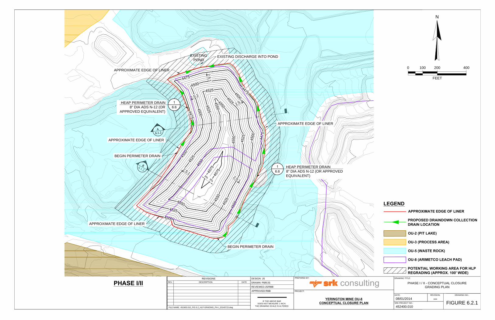
Prior to sideslope regrading, gravel-filled drains will be constructed within the existing draindown collection channels at each of the heap leach pads to facilitate collection of heap draindown during and after overdumping. The extent of drain construction within the existing heap perimeter channels has been determined based on available topography and leach pad construction details to ensure capture of as much draindown as possible. Figures 6.2.1 through 6.8 at the end of this section show conceptual drain alignments and drain construction details. Drain construction at each leach pad will include the following elements:
1. Clear the existing collection channel of all vegetation, debris, and sloughed heap material;
2. Inspect the channel, base and sideslopes for defects and repair in accordance with generally-accepted geomembrane repair procedures;
3. Place minimum 12-ounce-per-square-yard non-woven geotextile to channel base and sideslopes;
4. Place 4-inch-diameter perforated, corrugated polyethylene (PCPE – ADS N-12 or approved equivalent) drain pipe in base of channel;
5. Place drainage gravel over perforated drain pipe to a minimum depth of 6 inches over top of pipe;
6. Fold geotextile over drain rock with a minimum overlap of 5 feet; and
7. Carefully regrade spent ore over drain to outer edge of existing channel to protect drain during overdumping.
The perforated perimeter drain pipes will terminate in gravel-filled and geotextile-wrapped sumps at the perimeter channel low points where the flow currently exits the heap leach pads. Draindown will exit each leach pad sump location via gravity flow inside a solid 4-inch-diameter HDPE SDR17 pipe sealed inside an 8-inch-diameter HDPE SDR17 pipe booted into the sump lining. The pipe-in-pipe conveyance pipeline will route flows from each sump via gravity into the existing fluid management

SRK Consulting (U.S.), Inc. Yerington Mine OU-8 Conceptual Closure Plan Page 20
rbb/jp Yerington_OU-8_ConcClosurePlan_452400-010_rbb_20140818_Rev02 August 2014
system (sumps, ponds and transfer pipelines). Typical heap leach pad perimeter drain and sump details are shown on the drawings in Appendix A.
6.1.2 Leach Pad Regrading
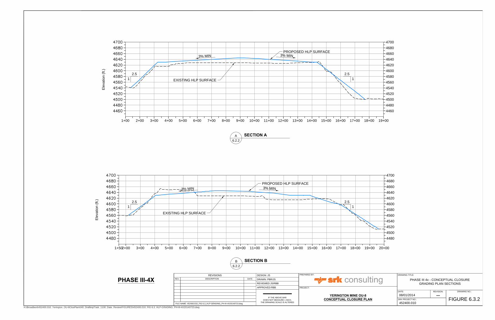
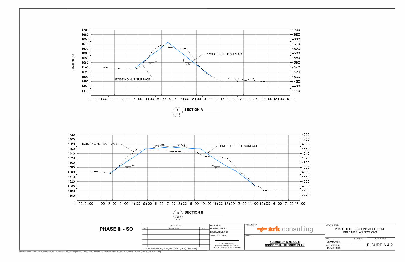
Conceptual sideslope grading plans have been developed using spent ore for balanced cut-to-fill where possible, and regraded to a slope of 2.5H:1V or shallower such that the toe of the regraded spent ore remains in containment within the existing lined pad limits. Where slope regrading to 2.5H:1V via a downhill push is not possible within the existing lined footprint, SRK assumes that heap leach pad material will be pushed down to the toe of the slope and hauled via truck and shovel back to the top surface of the leach pad because regrading by uphill dozer push is not an effective or efficient means of slope regrading. Drawings 101 through 105 in Appendix A delineate those areas where efficient regrading via cut-to-fill is possible, and also those areas where the existing slope is too steep and close to the edge of liner to facilitate cut-to-fill regrading and thus cut-to-haul is required. Figures 6.2.1 through 6.6.1 show conceptual regrading plans for the heap leach pads, and include estimated areas along the toe of each pad that may be required to accomplish the regrade-to-haul work described above.
Top surface regrading currently assumes final leach pad surfaces will be regraded to a minimum final grade of 3 percent to prevent ponding of surface water. In some cases, such as regrading-to-haul from Phase I/II to the Phase IV-SLOT pad, leach pad material will be transferred to a nearby pad to accomplish top surface grading requirements. Detailed heap leach pad regrading plans will be developed as part of detailed closure design, and will include specifications for moisture conditioning and compaction during spent ore regrading to minimize the potential for differential settlement and consequent ponding and provide a firm, non-yielding foundation for final cover construction.
6.1.3 Cover Placement
A detailed study evaluating the availability of borrow material and suitability for use as final cover is described in Section 2.8 above. The results of the study indicate native alluvium (West Sub-Area A-2, South Sub-Area A-2, and Sub-Area A-1 on Figure 6.1) ranks most favorable and soil from the South Waste Rock Area is second-most favorable with respect to the six characteristic categories. The sulfide tailings material ranks third most-favorable. The study concludes that suitable capping material exists on-site in the existing South Waste Rock area in sufficient quantities to support cover placement on the heap leach pads, and that this material would not require screening before transport or placement. The use of the South Waste Rock Dump material for heap leach pad cover construction was also used as the basis of the cost estimates presented with the Feasibility Study (CH2M Hill, 2012).
The final cover material used in heap leach pad closure should also be based on infiltration modeling using the unsaturated flow characteristics of available material, in addition to availability and associated hauling costs, to be completed as part of detailed design. In addition, because closure activities at the Yerington Mine not associated with OU-8 closure will also require cover material, the sitewide requirements for borrow soil should be considered when deciding which source to use for a particular site element. Table 6.1 was developed to summarize the potentially-available volume of each cover type based on exploration and sampling depths described in Brown and Caldwell (2011b). Figure 6.1 shows the identified borrow area footprints and haul distances from the approximate center of each area to each of the heap leach pads.

SRK Consulting (U.S.), Inc. Yerington Mine OU-8 Conceptual Closure Plan Page 21
rbb/jp Yerington_OU-8_ConcClosurePlan_452400-010_rbb_20140818_Rev02 August 2014
Table 6.1. Estimated Available Cover Material
Borrow Source Estimate Footprint
Area (acres) Depth (ft) Volume (cy)
Alluvium - West Sub-Area A-2 630 3 3,047,000
Alluvium – South Sub-Area A-2 352 3 1,702,000 Alluvium - Sub-Area A-1 (southern portion only)
738 3 3,572,000
South WRD 389 8 5,015,000
Sulfide Tailings 674 8 8,700,000
Oxide Tailings 344 4 2,220,000
S-23 Ore WRD 19 8 242,000
W-3 WRD 84 8 1,087,000
TOTAL 25,585,000
Note that Alternative 8 as described in the Feasibility Study (CH2M Hill, 2012) assumed a 4-foot-thick cover layer requiring 1.85 million cubic yards. The current conceptual closure plan includes placement of only 2 feet of cover soil, which is consistent with a number of currently-approved closure plans for heap leach pads throughout Nevada. Based on the quantities presented in the Feasibility Study (CH2M Hill, 2012), a 2-foot-thick cover layer would require approximately 925,000 cubic yards of cover soil. Unsaturated cover infiltration modeling should be performed to determine the most appropriate final cover thickness based on available soil borrow materials.
6.1.4 Stormwater Management
Management of stormwater runoff is only specifically addressed in the Feasibility Study (CH2M Hill, 2012) under the description of Alternative 7, which states that stormwater runoff from closed and covered heap surfaces will be managed in the existing fluid management system until sampling and analysis indicates it is clean enough for direct discharge to a nearby wash or drainage. The Feasibility Study (CH2M Hill, 2012) also states that stormwater will not be discharged anywhere within OU-8 due to the potential to pick up surface contamination.
There is currently no plan for comprehensive management of stormwater between OUs at the Yerington Mine. SRK assumed for the purposes of conceptual closure planning that non-contact stormwater runoff from closed individual OU-8 components will ultimately be conveyed in open channels or above-ground pipelines either to the Yerington Pit (for Phase IV Slot HLP) or to the sulfide tailings area (OU-4) via the same alignment as the existing gravity draindown conveyance pipeline (all other HLPs). Detailed leach pad closure design should also consider sitewide stormwater management requirements.
A conceptual stormwater control system was developed based on available topography and the existing draindown conveyance pipeline alignment. The conceptual layout of the network of stormwater control channels is shown on Figure 6.7. A conceptual channel configuration detail is shown on Figure 6.8. Preliminary hydrologic evaluations indicate a trapezoidal channel approximately 3 feet deep with a base width of 12 feet and 2H:1V sideslopes will be sufficient to convey stormwater from the closed heap leach pads and surrounding contributing areas to either the exiting Yerington Pit Lake or the sulfide tailings area. Riprap lining will likely be required over most of the channel to prevent in-channel erosion. A detailed watershed evaluation and stormwater control system design will be necessary to confirm the conceptual system design configuration.
6.1.5 Conversion of Ponds to E-Cells
As described above, the goal of OU-8 heap leach pad conceptual closure is to minimize precipitation input to the existing water management system. SRK recommends maintaining the existing fluid

SRK Consulting (U.S.), Inc. Yerington Mine OU-8 Conceptual Closure Plan Page 22
rbb/jp Yerington_OU-8_ConcClosurePlan_452400-010_rbb_20140818_Rev02 August 2014
management system until the existing draindown flows are sufficiently low to allow for passive evaporation in all or a part of the existing fluid management system. To develop the post-closure fluid management plan, draindown from each heap leach pad should be measured regularly. At the appropriate time, some or all of the existing ponds should be converted to soil-filled double-lined evaporation cells (E-Cells) with sufficient volume and surface area to store and eliminate through evaporation (i.e., passively) the combined precipitation and seepage inventory generated on an annual basis from the measured post-closure seepage flow rates. A detailed water balance should be prepared for each pond using the monitoring record to predict evaporation cell performance and maintain fluid levels in the pond within the soil backfill. Although it is feasible that volunteer vegetation may become established within the E-Cells and provide for additional reduction in E-Cell fluid inventory, E-Cell design criteria should ignore this potential and allow for evaporation from a backfilled soil surface only. In addition to draindown seepage flows, the E-Cells should be of sufficient size to temporarily manage 100-year, 24-hour storm precipitation (3.01 inches) falling within the cell perimeter and provide at least two feet of freeboard to eliminate overtopping risks. Construction tasks required to convert the ponds will include, at a minimum:
1. Removal/evaporation of existing pond inventory;
2. Removal of pond sediments;
3. Inspect and repair existing liner;
4. Construct gravel-filled sump in lowest corner of the pond, to include vertical HDPE monitoring riser pipe;
5. Place geonet and primary 80 mil single-sided textured HDPE liner (texture up) or 80 mill Agru Drain Liner to pond base and sideslopes;
6. Backfill pond with 3 feet of nominally-compacted relatively fine-grained alluvium;
7. Excavated to within 6 inches of liner a network of seepage distribution trenches;
8. Line trench system with 8 oz/sy non-woven, needle-punched geomembrane;
9. Place 4-inch perforated corrugated polyethylene pipe (ADS N-12 or approved equivalent) in base of trenches and connect to form subsurface seepage distribution system;
10. Backfill trenches with clean drain rock to within 6 inches of backfill surface and overlap geotextile on top;
11. Backfill remainder of trench with 6 inches of relatively fine-grained alluvium;
12. Place additional 6 inches of relatively fine-grained alluvium over backfilled pond surface;
13. During pond backfilling, install vertical riser piezometer within pond backfill to monitor saturations levels in backfill; and
14. Install flow measurement point prior to discharge point into pond.
6.1.6 4-Acre Pond Closure
Options for reprocessing the precipitates and liquids in the 4-Acre Pond (Evaporation Pond A) are currently being evaluated. As such, the existing 4-Acre Pond will either be closed in-place by removal and reprocessing of the pond inventory or encapsulation. Encapsulation would require the pond contents be physically stabilized via the addition of cement or other stabilizing agent or through mixing with suitable borrow material to form a firm foundation sufficient for geomembrane liner installation and placement of a soil overliner layer with overliner infiltration drains. Additional characterization is required prior to selecting the preferred alternative for closure of the 4-Acre Pond.

SRK Consulting (U.S.), Inc. Yerington Mine OU-8 Conceptual Closure Plan Page 23
rbb/jp Yerington_OU-8_ConcClosurePlan_452400-010_rbb_20140818_Rev02 August 2014
6.1.7 Arimetco Process Area Closure
Closure of the Arimetco Process Area is discussed briefly in Section 1 of the Feasibility Study (CH2M Hill, 2012), which states that additional characterization is recommended to determine the nature and extent of contamination present prior to closure. It is important that the additional characterization be completed prior to heap leach pad closure since a common method for management of soils impacted by heap leaching operations is to remove them to the top of a leach pad prior to closure and cover placement.

SOUTHSUB-AREA
A-1
PHASE III4X HLP
PHASE IV VLT HLP
PHASE IVSLOT HLP
PHASE I & II HLP
PHASE IIISOUTH HLP
OXIDETAILINGS
SOUTHWRD
S-23WRD
WESTSUB-AREA
A-2
SULFIDETAILINGS
W-3 WRD
NORTH SUB-AREA
A-1
SOUTHSUB-AREA
A-2
Imagery ©2014
H:\Broadbent\452400.010_Yerington_OU-8ClosPlan\040_Drafting\Task_1100_Date_Review\Haulroute_Calculations_alt.mxd
452400.010
DATE: 8/13/2014 DRAWING NO.
FIGURE 6.1
REV. NO.
A
DRAWING TITLE:
BORROW SOURCE HAUL DISTANCES
CONCEPTUALIF THE ABOVE BAR DOES NOT SCALE 1 INCH, THE DRAWING
SCALE IS ALTERED
NAD 1983 UTM Zone 11N
DESIGN:
DRAWN:
REVIEWED:
CHECKED:
APPROVED:
JS
-
JS/RBB
JS/RBBBCHREVISIONSDESCRIPTION DATEREV
FILE NAME: Haulroute_Calculations_alt.mxd
COORDINATE SYSTEM:
PROJECT:
SRK JOB #:
YERINGTON MINEOPERABLE UNIT 8
PREPARED FOR:
1 in = 2,000 feet
0 2,0001,000
EXPLANATION
OU-2
OU-3
OU-4
OU-5
OU-6
OU-8
Row Labels Phase I/II HLP Phase III 4X HLP Phase III South HLP Phase IV Slot HLP Phase IV VLT HLPOxide Tailings 11,406 4,258 4,770 11,257 2,951Sulfide Tailings 11,623 9,758 8,104 12,787 11,179S-23 Ore WRD 2,842 9,084 3,262 3,994 10,459South WRD 9,921 18,391 12,659 9,425 19,854W-3 WRD 2,837 12,317 6,488 3,285 13,688South Sub-Area A-1 17,561 8,070 10,776 17,263 13,194West Sub-Area A-2 20,281 10,775 13,482 19,969 15,900South Sub-Area A-2 14,552 23,017 17,301 14,050 24,492Note: North Sub-Area A-1 not considered for Soil Borrow.
Distance to Heap Leach Location (ft.)
Note: Potential Borrow Areas from Brown & Caldwell
EXISTING
POND
3
%
APPROXIMATE EDGE OF LINER
2
.
5
:
1
2
.
5
:
1
2
.
5
:
1
2
.
5
:
1
2
.5
:1
HEAP PERIMETER DRAIN
8" DIA ADS N-12 (OR APPROVED
EQUIVALENT)
HEAP PERIMETER DRAIN
8" DIA ADS N-12 (OR
APPROVED EQUIVALENT)
APPROXIMATE EDGE OF LINER
BEGIN PERIMETER DRAIN
APPROXIMATE EDGE OF LINER
APPROXIMATE EDGE OF LINER
EXISTING DISCHARGE INTO POND
BEGIN PERIMETER DRAIN
N
FEET
4002000 100
IF THE ABOVE BAR
DOES NOT MEASURE 1 INCH,
THE DRAWING SCALE IS ALTERED
PROJECT:
PREPARED BY:
PHASE I / II - CONCEPTUAL CLOSURE
GRADING PLAN
DESIGN: JS
DRAWN: PBR/JS
REVIEWED:JS/RBB
APPROVED:RBB
YERINGTON MINE OU-8CONCEPTUAL CLOSURE PLAN
FIGURE 6.2.1
452400.010
REVISION: DRAWING NO.:
08/01/2014
DATE:
SRK PROJECT NO.:
DRAWING TITLE:
FILE NAME: 452400.010_FIG 6.2_HLP-GRADING_PH-I_20140723.dwg
REV. DATE
REVISIONS
DESCRIPTION
---
LEGENDAPPROXIMATE EDGE OF LINER
PROPOSED DRAINDOWN COLLECTIONDRAIN LOCATION
OU-2 (PIT LAKE)
OU-3 (PROCESS AREA)
OU-5 (WASTE ROCK)
OU-8 (ARIMETCO LEACH PAD)
POTENTIAL WORKING AREA FOR HLPREGRADING (APPROX. 100' WIDE)
PHASE I/II

Ele
va
tio
n (ft.)
Elevation (ft.)
SECTION 2
Station (ft.)
IF THE ABOVE BAR
DOES NOT MEASURE 1 INCH,
THE DRAWING SCALE IS ALTERED
PROJECT:
PREPARED BY:
PHASE I / II - CONCEPTUAL CLOSURE
GRADING PLAN SECTIONS
DESIGN: JS
DRAWN: PBR/JS
REVIEWED:JS/RBB
APPROVED:RBB
YERINGTON MINE OU-8CONCEPTUAL CLOSURE PLAN
FIGURE 6.2.2
452400.010
REVISION: DRAWING NO.:
08/01/2014
DATE:
SRK PROJECT NO.:
DRAWING TITLE:
FILE NAME: 452400.010_FIG 6.2_HLP-GRADING_PH-I_20140723.dwg
REV. DATE
REVISIONS
DESCRIPTION
---
SECTION AA
6.1.2
SECTION BB
6.1.2
PROPOSED HLP SURFACE
EXISTING HLP SURFACE
PROPOSED HLP SURFACE
EXISTING HLP SURFACE
2.5
1
2.5
1
PHASE I/II
2.5
1
2.5
1

3
%
3
%
2
.5
:1
2.5
:1
2
.
5
:
1
2.5
:1
2
.
5
:
1
2
.
5
:
1
2.5
:1
HEAP PERIMETER DRAIN
8" DIA ADS N-12 (OR
APPROVED EQUIVALENT
APPROXIMATE EDGE OF LINER
BEGIN PERIMETER DRAIN
LINED
CONVEYANCE
CHANNEL
EXISTING DISCHARGE
APPROXIMATE EDGE OF LINER
HEAP PERIMETER DRAIN
8" DIA ADS N-12 (OR
APPROVED EQUIVALENT
APPROXIMATE EDGE OF LINER
HEAP PERIMETER DRAIN
8" DIA ADS N-12 (OR
APPROVED EQUIVALENT
BEGIN PERIMETER DRAIN
NORTH MEGA SUMP
N
FEET
6003000 150
H:\Broadbent\452400.010_Yerington_OU-8ClosPlan\040_Drafting\Task_1100_Date_Review\FIGURES\452400.010_FIG 6.3_HLP-GRADING_PH-III-4X20140723.dwg
IF THE ABOVE BAR
DOES NOT MEASURE 1 INCH,
THE DRAWING SCALE IS ALTERED
PROJECT:
PREPARED BY:
PHASE III 4x - CONCEPTUAL CLOSURE
GRADING PLAN
DESIGN: JS
DRAWN: PBR/JS
REVIEWED:JS/RBB
APPROVED:RBB
YERINGTON MINE OU-8CONCEPTUAL CLOSURE PLAN
FIGURE 6.3.1
452400.010
REVISION: DRAWING NO.:
08/01/2014
DATE:
SRK PROJECT NO.:
DRAWING TITLE:
FILE NAME: 452400.010_FIG 6.3_HLP-GRADING_PH-III-4X20140723.dwg
REV. DATE
REVISIONS
DESCRIPTION
---
H:\Broadbent\452400.010_Yerington_OU-8ClosPlan\040_Drafting\Task_1100_Date_Review\FIGURES\452400.010_FIG 6.3_HLP-GRADING_PH-III-4X20140723.dwg
PHASE III-4X
LEGENDAPPROXIMATE EDGE OF LINER
PROPOSED DRAINDOWN COLLECTIONDRAIN LOCATION
OU-3 (PROCESS AREA)
OU-6 (OXIDE TAILINGS
OU-8 (ARIMETCO LEACH PAD)
POTENTIAL WORKING AREA FOR HLPREGRADING (APPROX. 100' WIDE)
Ele
va
tio
n (ft.)
SECTION 1
4460
4480
4500
4520
4540
4560
4580
4600
4620
4640
4660
4680
4700
1+00 2+00 3+00 4+00 5+00 6+00 7+00 8+00 9+00 10+00 11+00 12+00 13+00 14+00 15+00 16+00 17+00 18+00 19+00
Ele
va
tio
n (ft.)
4480
4500
4520
4540
4560
4580
4600
4620
4640
4660
4680
4700
1+502+00 3+00 4+00 5+00 6+00 7+00 8+00 9+00 10+00 11+00 12+00 13+00 14+00 15+00 16+00 17+00 18+00 19+00 20+00
H:\Broadbent\452400.010_Yerington_OU-8ClosPlan\040_Drafting\Task_1100_Date_Review\FIGURES\452400.010_FIG 6.3_HLP-GRADING_PH-III-4X20140723.dwg
IF THE ABOVE BAR
DOES NOT MEASURE 1 INCH,
THE DRAWING SCALE IS ALTERED
PROJECT:
PREPARED BY:
PHASE III 4x - CONCEPTUAL CLOSURE
GRADING PLAN SECTIONS
DESIGN: JS
DRAWN: PBR/JS
REVIEWED:JS/RBB
APPROVED:RBB
YERINGTON MINE OU-8CONCEPTUAL CLOSURE PLAN
FIGURE 6.3.2
452400.010
REVISION: DRAWING NO.:
08/01/2014
DATE:
SRK PROJECT NO.:
DRAWING TITLE:
FILE NAME: 452400.010_FIG 6.3_HLP-GRADING_PH-III-4X20140723.dwg
REV. DATE
REVISIONS
DESCRIPTION
---
H:\Broadbent\452400.010_Yerington_OU-8ClosPlan\040_Drafting\Task_1100_Date_Review\FIGURES\452400.010_FIG 6.3_HLP-GRADING_PH-III-4X20140723.dwg
SECTION AA
6.2.2
SECTION BB
6.2.2
PROPOSED HLP SURFACE
EXISTING HLP SURFACE
PROPOSED HLP SURFACE
EXISTING HLP SURFACE
2.5
1
3% M
IN
3% M
IN
3% M
IN
3% M
IN
2.5
1
2.5
1
2.5
1
PHASE III-4X

2
.
5
:
1
2.5:1
2.5:1
2
.
5
:
1
3
%
3
%
2.5
:1
2
.
5
:
1
2
.
5
:
1
2
.5
:1
HEAP PERIMETER DRAIN
8" DIA ADS N-12 (OR
APPROVED EQUIVALENT)
HEAP PERIMETER DRAIN
8" DIA ADS N-12 (OR
APPROVED EQUIVALENT)
HEAP PERIMETER DRAIN
8" DIA NADS N-12 (OR
APPROVED EQUIVALENT)
APPROXIMATE EDGE OF LINER
APPROXIMATE EDGE OF LINER
APPROXIMATE EDGE OF LINER
APPROXIMATE EDGE OF LINER
APPROXIMATE EDGE OF LINER
APPROXIMATE EDGE OF LINER
BEGIN PERIMETER DRAIN
SOUTH MEGA SUMP
DROP INLET TO CONVEYANCE
PIPELINE
NORTH MEGA SUMP
DROP INLET TO CONVEYANCE
PIPELINE
LINED CONVEYANCE CHANNEL
EXISTING DISCHARGE INTO
COLLECTION POINT
BEGIN PERIMETER DRAIN
N
FEET
700.00013500 175
PHASE III - SO
H:\Broadbent\452400.010_Yerington_OU-8ClosPlan\040_Drafting\Task_1100_Date_Review\FIGURES\452400.010_FIG 6.4_HLP-GRADING_PH-III_20140723.dwg
IF THE ABOVE BAR
DOES NOT MEASURE 1 INCH,
THE DRAWING SCALE IS ALTERED
PROJECT:
PREPARED BY:
PHASE III SO - CONCEPTUAL CLOSURE
GRADING PLAN
DESIGN: JS
DRAWN: PBR/JS
REVIEWED:JS/RBB
APPROVED:RBB
YERINGTON MINE OU-8CONCEPTUAL CLOSURE PLAN
FIGURE 6.4.1
452400.010
REVISION: DRAWING NO.:
08//01/2014
DATE:
SRK PROJECT NO.:
DRAWING TITLE:
FILE NAME: 452400.010_FIG 6.4_HLP-GRADING_PH-III_20140723.dwg
REV. DATE
REVISIONS
DESCRIPTION
---
H:\Broadbent\452400.010_Yerington_OU-8ClosPlan\040_Drafting\Task_1100_Date_Review\FIGURES\452400.010_FIG 6.4_HLP-GRADING_PH-III_20140723.dwg
LEGENDAPPROXIMATE EDGE OF LINER
PROPOSED DRAINDOWN COLLECTIONDRAIN LOCATION
OU-3 (PROCESS AREA)
OU-4 (SULFIDE TAILINGS)
OU-5 (WASTE ROCK)
OU-6 (OXIDE TAILINGS
OU-8 (ARIMETCO LEACH PAD)
POTENTIAL WORKING AREA FOR HLPREGRADING (APPROX. 100' WIDE)
Ele
va
tio
n (ft.)
PHASE III - SO
H:\Broadbent\452400.010_Yerington_OU-8ClosPlan\040_Drafting\Task_1100_Date_Review\FIGURES\452400.010_FIG 6.4_HLP-GRADING_PH-III_20140723.dwg
IF THE ABOVE BAR
DOES NOT MEASURE 1 INCH,
THE DRAWING SCALE IS ALTERED
PROJECT:
PREPARED BY:
PHASE III SO - CONCEPTUAL CLOSURE
GRADING PLAN SECTIONS
DESIGN: JS
DRAWN: PBR/JS
REVIEWED:JS/RBB
APPROVED:RBB
YERINGTON MINE OU-8CONCEPTUAL CLOSURE PLAN
FIGURE 6.4.2
452400.010
REVISION: DRAWING NO.:
08/01/2014
DATE:
SRK PROJECT NO.:
DRAWING TITLE:
FILE NAME: 452400.010_FIG 6.4_HLP-GRADING_PH-III_20140723.dwg
REV. DATE
REVISIONS
DESCRIPTION
---
H:\Broadbent\452400.010_Yerington_OU-8ClosPlan\040_Drafting\Task_1100_Date_Review\FIGURES\452400.010_FIG 6.4_HLP-GRADING_PH-III_20140723.dwg
PROPOSED HLP SURFACE
EXISTING HLP SURFACE
EXISTING HLP SURFACE
SECTION AA
6.3.2
SECTION BB
6.3.2
PROPOSED HLP SURFACE
2.5
1
2.5
1
2.5
1
2.5
1
3% M
IN3%
MIN

3
%
3
%
3
%
3
%
2.5:1
2
.
5
:
1
2
.
5
:
1
2
.5
:1
2
.
5
:
1
2.5:1
2
.
5
:
1
BEGIN PERIMETER DRAIN
BEGIN PERIMETER DRAIN
APPROXIMATE EDGE OF LINER
APPROXIMATE EDGE OF LINER
APPROXIMATE EDGE OF LINER
EXISTING DISCHARGE INTO POND
EXISTING POND
HEAP PERIMETER DRAIN
8" DIA ADS N-12 (OR
APPROVED EQUIVALENT)
HEAP PERIMETER DRAIN
8" DIA ADS N-12 (OR
APPROVED EQUIVALENT)
N
FEET
6003000 150
H:\Broadbent\452400.010_Yerington_OU-8ClosPlan\040_Drafting\Task_1100_Date_Review\FIGURES\452400.010_FIG 6.5_HLP-GRADING_PH-IV-SLOT_20140723 .dwg
IF THE ABOVE BAR
DOES NOT MEASURE 1 INCH,
THE DRAWING SCALE IS ALTERED
PROJECT:
PREPARED BY:
PHASE IV SLOT - CONCEPTUAL CLOSURE
GRADING PLAN
DESIGN: JS
DRAWN: PBR/JS
REVIEWED:JS/RBB
APPROVED:RBB
YERINGTON MINE OU-8CONCEPTUAL CLOSURE PLAN
FIGURE 6.5.1
452400.010
REVISION: DRAWING NO.:
08/01/2014
DATE:
SRK PROJECT NO.:
DRAWING TITLE:
FILE NAME: 452400.010_FIG 6.5_HLP-GRADING_PH-IV-SLOT_20140723.dwg
REV. DATE
REVISIONS
DESCRIPTION
---
H:\Broadbent\452400.010_Yerington_OU-8ClosPlan\040_Drafting\Task_1100_Date_Review\FIGURES\452400.010_FIG 6.5_HLP-GRADING_PH-IV-SLOT_20140723 .dwg
LEGENDAPPROXIMATE EDGE OF LINER
PROPOSED DRAINDOWN COLLECTIONDRAIN LOCATION
OU-2 (PIT LAKE)
OU-5 (WASTE ROCK)
OU-8 (ARIMETCO LEACH PAD)
POTENTIAL WORKING AREA FOR HLPREGRADING (APPROX. 100' WIDE)
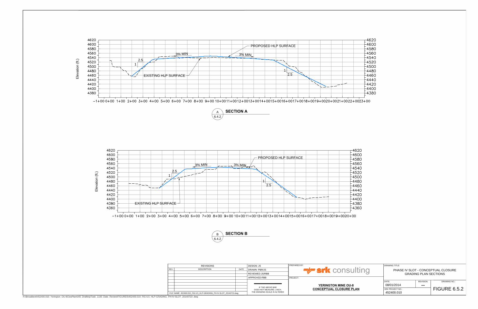
Ele
va
tio
n (ft.)
Ele
va
tio
n (ft.)
SECTION 2
H:\Broadbent\452400.010_Yerington_OU-8ClosPlan\040_Drafting\Task_1100_Date_Review\FIGURES\452400.010_FIG 6.5_HLP-GRADING_PH-IV-SLOT_20140723 .dwg
IF THE ABOVE BAR
DOES NOT MEASURE 1 INCH,
THE DRAWING SCALE IS ALTERED
PROJECT:
PREPARED BY:
PHASE IV SLOT - CONCEPTUAL CLOSURE
GRADING PLAN SECTIONS
DESIGN: JS
DRAWN: PBR/JS
REVIEWED:JS/RBB
APPROVED:RBB
YERINGTON MINE OU-8CONCEPTUAL CLOSURE PLAN
FIGURE 6.5.2
452400.010
REVISION: DRAWING NO.:
08/01/2014
DATE:
SRK PROJECT NO.:
DRAWING TITLE:
FILE NAME: 452400.010_FIG 6.5_HLP-GRADING_PH-IV-SLOT_20140723.dwg
REV. DATE
REVISIONS
DESCRIPTION
---
H:\Broadbent\452400.010_Yerington_OU-8ClosPlan\040_Drafting\Task_1100_Date_Review\FIGURES\452400.010_FIG 6.5_HLP-GRADING_PH-IV-SLOT_20140723 .dwg
EXISTING HLP SURFACE
SECTION AA
6.4.2
PROPOSED HLP SURFACE
EXISTING HLP SURFACE
SECTION BB
6.4.2
PROPOSED HLP SURFACE
2.5
1
2.5
1
3% M
IN
3% M
IN
2.5
1
3% M
IN3%
MIN
2.5
1

2
.
5
:
1
2
.
5
:
1
2
.
5
:
1
2.5:1
3
.4
%
3
.0
%
3
.
6
%
3
.
3
%
BEGIN PERIMETER DRAIN
EXISTING DISCHARGE INTO POND
APPROXIMATE EDGE OF LINER
EXISTING VLT POND
EXISTING SEDIMENT CONTROL BASIN
W/LINED OVERFLOW CHANNEL TO VLT POND
APPROXIMATE EDGE OF LINER
BEGIN
PERIMETER
DRAIN
HEAP PERIMETER DRAIN
8" DIA ADS N-12 (OR
APPROVED EQUIVALENT)
HEAP PERIMETER DRAIN
8" DIA ADS N-12 (OR
APPROVED EQUIVALENT)
HEAP PERIMETER DRAIN
8" DIA ADS N-12 (OR
APPROVED EQUIVALENT)
N
FEET
6003000 150
H:\Broadbent\452400.010_Yerington_OU-8ClosPlan\040_Drafting\Task_1100_Date_Review\FIGURES\452400.010_FIG 6.6_HLP-GRADING_PH-IV-VLT_20140723.dwg
IF THE ABOVE BAR
DOES NOT MEASURE 1 INCH,
THE DRAWING SCALE IS ALTERED
PROJECT:
PREPARED BY:
PHASE IV - VLT - CONCEPTUAL CLOSURE
GRADING PLAN
DESIGN: JS
DRAWN: PBR/JS
REVIEWED:JS/RBB
APPROVED:RBB
YERINGTON MINE OU-8CONCEPTUAL CLOSURE PLAN
FIGURE 6.6.1
452400.010
REVISION: DRAWING NO.:
08/01/2014
DATE:
SRK PROJECT NO.:
DRAWING TITLE:
FILE NAME: 452400.010_FIG 6.6_HLP-GRADING_PH-IV-VLT_20140723.dwg
REV. DATE
REVISIONS
DESCRIPTION
---
H:\Broadbent\452400.010_Yerington_OU-8ClosPlan\040_Drafting\Task_1100_Date_Review\FIGURES\452400.010_FIG 6.6_HLP-GRADING_PH-IV-VLT_20140723.dwg
LEGENDAPPROXIMATE EDGE OF LINER
PROPOSED DRAINDOWN COLLECTIONDRAIN LOCATION
OU-4 (SULFIDE TAILINGS)
OU-6 (OXIDE TAILINGS
OU-8 (ARIMETCO LEACH PAD)
POTENTIAL WORKING AREA FOR HLPREGRADING (APPROX. 100' WIDE)

Ele
va
tio
n (ft.)
SECTION 1
Ele
va
tio
n (ft.)
SECTION 1
H:\Broadbent\452400.010_Yerington_OU-8ClosPlan\040_Drafting\Task_1100_Date_Review\FIGURES\452400.010_FIG 6.6_HLP-GRADING_PH-IV-VLT_20140723.dwg
IF THE ABOVE BAR
DOES NOT MEASURE 1 INCH,
THE DRAWING SCALE IS ALTERED
PROJECT:
PREPARED BY:
PHASE IV - VLT - CONCEPTUAL CLOSURE
GRADING PLAN SECTIONS
DESIGN: JS
DRAWN: PBR/JS
REVIEWED:JS/RBB
APPROVED:RBB
YERINGTON MINE OU-8CONCEPTUAL CLOSURE PLAN
FIGURE 6.6.2
452400.010
REVISION: DRAWING NO.:
08/01/2014
DATE:
SRK PROJECT NO.:
DRAWING TITLE:
FILE NAME: 452400.010_FIG 6.6_HLP-GRADING_PH-IV-VLT_20140723.dwg
REV. DATE
REVISIONS
DESCRIPTION
---
H:\Broadbent\452400.010_Yerington_OU-8ClosPlan\040_Drafting\Task_1100_Date_Review\FIGURES\452400.010_FIG 6.6_HLP-GRADING_PH-IV-VLT_20140723.dwg
EXISTING HLP SURFACE
SECTION AA
6.5.2
PROPOSED HLP SURFACE
EXISTING HLP SURFACE
SECTION BB
6.5.2
PROPOSED HLP SURFACE
2.5
1
2.5
1
3% M
IN
3% M
IN
2.5
1
2.5
1
3% M
IN
3% M
IN

SEDIMENT POND
SLOT 2 POND
VLT POND
SLOT SEDIMENTPOND
PHASE III SOUTH HEAPLEACH PAD
PHASE III 4X HEAPLEACH PAD
PHASE IV VLTHEAP LEACH PAD
EVAPORATIONPOND A
PHASE I HEAPLEACH PAD
PHASE II HEAPLEACH PAD
EVAPORATIONPONDS B & C
PHASE I POND
PHASE IV SLOTHEAP LEACH PAD
WEED HEIGHTS
12" WIDE TRAPEZOIDAL
DITCH (TYP)
4
1
2
3
5
8
6
7
9
10
12
11
10
ARIMETCOPROCESS AREA
H:\Broadbent\452400.010_Yerington_OU-8ClosPlan\040_Drafting\Task_1100_Date_Review\FIGURES\Yerington_HLP_Flow_20140729_LEB.dwg
N
FEET
10005000
IF THE ABOVE BAR
DOES NOT MEASURE 1 INCH,
THE DRAWING SCALE IS ALTERED
PROJECT:
PREPARED BY:
CONCEPTUAL STORMWATER CONTROL
SYSTEM DESIGN
DESIGN: XXX
DRAWN: BCH
REVIEWED: XXX
APPROVED: XXX
YERINGTON MINEOPERABLE UNIT 8
FIGURE 6.7
---
452400.010
REVISION: DRAWING NO.:
08/01/2014
DATE:
SRK PROJECT NO.:
DRAWING TITLE:
FILE NAME: Yerington_HLP_Flow_20140729_LEB.dwg
REV. DATEDESCRIPTION
REVISIONS
LEGENDOU LIMITS
12' TRAPEZOIDAL DITCH
CHANNEL SEGMENT DELINEATION8
OU-2 (PIT LAKE)
OU-3 (PROCESS AREA)
OU-4 (SULFIDE TAILINGS)
OU-5 (WASTE ROCK)
OU-6 (OXIDE TAILINGS
OU-8 (ARIMETCO LEACH PAD)
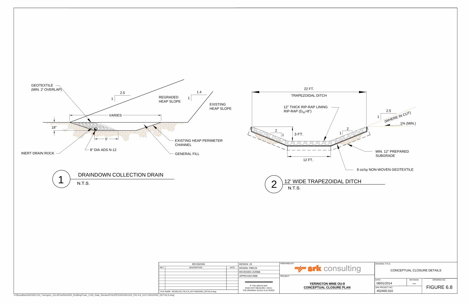
5'
18"
VARIES
8" DIA ADS N-12
INERT DRAIN ROCK
1
DRAINDOWN COLLECTION DRAIN
EXISTING
HEAP SLOPE
12' WIDE TRAPEZOIDAL DITCH
EXISTING HEAP PERIMETER
CHANNEL
GEOTEXTILE
(MIN. 2' OVERLAP)
REGRADED
HEAP SLOPE
GENERAL FILL
22 FT.
1% (MIN.)
TRAPEZOIDAL DITCH
2.5
1
2
1
(
W
H
E
R
E
I
N
C
U
T
)
12 FT.
8 oz/sy NON-WOVEN GEOTEXTILE
MIN. 12" PREPARED
SUBGRADE
2
1
12" THICK RIP-RAP LINING
RIP-RAP (D
50
=8")
2
2.5
1
1.4
1
H:\Broadbent\452400.010_Yerington_OU-8ClosPlan\040_Drafting\Task_1100_Date_Review\FIGURES\452400.010_FIG 6.8_HLP-GRADING_DETAILS.dwg
IF THE ABOVE BAR
DOES NOT MEASURE 1 INCH,
THE DRAWING SCALE IS ALTERED
PROJECT:
PREPARED BY:
CONCEPTUAL CLOSURE DETAILS
DESIGN: JS
DRAWN: PBR/JS
REVIEWED:JS/RBB
APPROVED:RBB
YERINGTON MINE OU-8
CONCEPTUAL CLOSURE PLAN
FIGURE 6.8
452400.010
REVISION: DRAWING NO.:
08/01/2014
DATE:
SRK PROJECT NO.:
DRAWING TITLE:
FILE NAME: 452400.010_FIG 6.8_HLP-GRADING_DETAILS.dwg
REV. DATE
REVISIONS
DESCRIPTION
---
H:\Broadbent\452400.010_Yerington_OU-8ClosPlan\040_Drafting\Task_1100_Date_Review\FIGURES\452400.010_FIG 6.8_HLP-GRADING_DETAILS.dwg

SRK Consulting (U.S.), Inc. Yerington Mine OU-8 Conceptual Closure Plan Page 37
rbb/jp Yerington_OU-8_ConcClosurePlan_452400-010_rbb_20140818_Rev02 August 2014
7 Post-Closure Fluid Management Prior to and following construction of heap leach pad stabilization measures, heap draindown flow rates and chemistry from each pad should be monitored at least monthly to evaluate and demonstrate the effects of the proposed heap leach pad stabilization actions, and when required, provide data for final design of a long-term fluid management system (e.g., evaporation cell). Current operation and maintenance activities and the existing fluid management system should be monitored and maintained during closure construction and until post-closure fluid management requirements have been adequately evaluated, at which time a smaller network of evaporation cells utilizing the ponds at each heap leach pad is envisioned to manage long-term draindown flows. Conveyance of draindown flows through long pipelines to distant ponds should be avoided to minimize maintenance requirements.
As described in Section 6.1.4 above, following heap leach pad closure, stormwater should be managed as part of a sitewide stormwater management plan.
8 Closure Schedule and Prioritization Current experience with relatively rapid generation of salt precipitates in the 4-Acre Pond (over approximately 7 years) indicates the potential for significant long-term management costs associated with management of heap leach draindown. In addition, although the potential for reprocessing the precipitates is currently being evaluated, currently-identified management alternatives for salt precipitates are fairly limited.
Based on this, prioritization of closure activities should focus on reducing inputs to the fluid management system as soon as possible to minimize expensive and labor-intensive fluid and salt precipitate management requirements. The most logical sequence of heap leach pad closure would therefore target the leach pads with the highest draindown rate.
As shown on Figure 5.1, the Phase IV VLT heap leach pad currently shows the highest draindown rate and an almost immediate response to precipitation events. Regrading and covering at this pad should therefore occur first, followed by the Phase IV Slot heap leach pad, the Phase III South and Phase III 4X heap leach pads, and finally the Phase I/II leach pads. Note that draindown from the Phase I/II pad is currently managed within the existing Phase I/II pond and does not require active management.
To confirm the prioritization described above and facilitate monitoring of post-closure success (i.e. reduction or elimination of draindown flow), installation of additional monitoring ports/locations to monitor individual draindown flow rates from each pad should be implemented immediately.
Characterization of the Arimetco Process Area and the potential for reprocessing of 4-Acre Pond precipitates should progress as soon as possible so that earthworks that may be required for closure of those site elements can proceed most efficiently during closure of nearby heap leach pads.
9 Additional Closure-Related Tasks The following additional closure-related tasks have been identified as necessary to support OU-8 closure:
1. Develop site-wide stormwater management plan to facilitate incorporation of OU-8 stormwater management;
2. Define site-wide cover material requirements to facilitate evaluation of the necessity to conserve or select specific cover materials to ensure availability for other site components, to include an

SRK Consulting (U.S.), Inc. Yerington Mine OU-8 Conceptual Closure Plan Page 38
rbb/jp Yerington_OU-8_ConcClosurePlan_452400-010_rbb_20140818_Rev02 August 2014
evaluation of the relative difficulty (BLM, permitting, acquisition, etc.) of borrow source acquisition;
3. Detailed design and preparation of construction drawing set for leach pad regrading, cover construction, and pond conversion to E-Cells, including the following:
a. Develop pond- and heap-specific water balances to evaluate the capacity of each available pond in managing draindown to evaluate long-term water management capabilities;
b. Complete infiltration modeling using HYDRUS 1D, 2D or similar to evaluate the relative performance of available cover materials, or combination of cover materials, to identify the most likely final cover configuration to limit infiltration (must consider the results of #2 above); and
c. Prepare Technical Specifications and Construction Quality Assurance Manual to ensure construction in accordance with the approved design.
SRK Consulting (U.S.), Inc. Yerington Mine OU-8 Conceptual Closure Plan Page 39
rbb/jp Yerington_OU-8_ConcClosurePlan_452400-010_rbb_20140818_Rev02 August 2014
10 References Brown and Caldwell, 2010, Arimetco Heap Leach Pad Fluid Management System, Operations and
Maintenance Plan, Yerington Mine Site, July 16, 2010.
Brown and Caldwell, 2011a, 2010 Annual Operations and Maintenance Report, Arimetco Heap Leach Pad Fluid Management System, Yerington Mine Site, June 2, 2011.
Brown and Caldwell, 2011b, Revised Data Summary Report for the Characterization of Potential Cover Materials, Yerington Mine Site, Lyon County, Nevada: Administrative Order on Consent, CERCLA Docket No. 09-2009-0010, June 10, 2011.
Brown and Caldwell, 2012, 2011 Annual Operations and Maintenance Report, Arimetco Heap Leach Pad Fluid Management System, Yerington Mine Site, June 25, 2012.
Brown and Caldwell, 2013, 2012 Annual Operations and Maintenance Report, Arimetco Heap Leach Pad Fluid Management System, Yerington Mine Site, September 25, 2013.
Brown and Caldwell, 2014a, Arimetco Heap Leach Pad Water Balance Analysis, March 25, 2014.
Brown and Caldwell, 2014b, 2013 Annual Operations and Maintenance Report, Arimetco Heap Leach Pad Fluid Management System, Yerington Mine Site, June 9, 2014.
CH2M HILL, 2011a, Final Remedial Investigation Report, Arimetco Facilities Operable Unit 8, Anaconda Yerington Copper Mine, September 2011.
CH2M HILL, 2011b, Supplemental Remedial Investigation Report, Arimetco Facilities Operable Unit 8, Anaconda Yerington Copper Mine, Yerington, Nevada, October 2011.
CH2M HILL, 2012, Draft Final Feasibility Study for Arimetco Facilities Operable Unit 8 Heap Leach Pads and Drain-down Fluids Anaconda-Yerington Copper Mine, Yerington, Nevada, May 2012.
Huxel, J.C.J., and Harris, E.E., 1969, Water Resources and Development in Mason Valley, Lyon and Mineral Counties 1948-1965, Water Resources Bulletin No. 38, Department of Conservation and Natural Resources, United States Geological Survey.
National Oceanic and Atmospheric Administration (NOAA), 2014, website available at: http://dipper.nws.noaa.gov/hdsc/pfds/.
Nevada Division of Environmental Protection, Bureau of Corrective Action (NDEP-BCA), 2014, Yerington OU-8 NDEP Proposal for Next Steps, February 6, 2014 Final Draft, 2014.
Sietz, H.R., A.S. Van Denburgh, and R.J. La Camera, 1982, Groundwater Quality Downgradient from Copper-Ore Milling Wastes at Weed Heights, Lyon County, Nevada, 1982, Prepared in cooperation with the Nevada Division of Environmental Protection, Open File Report 80-1217.
U.S. Environmental Protection Agency (EPA), 2008, Public Review Draft Remedial Investigation Report Arimetco Facilities Operable Unit 8, Anaconda Copper Yerington Mine, prepared by CH2H Hill, July 2008.
U.S. Geological Survey, 2014, Earthquake Archive Search & URL Builder, 2014, website available at: http://earthquake.usgs.gov/earthquakes/search/
Western Regional Climate Center, 2014, website available at: http://www.wrcc.dri.edu/.

SRK Consulting (U.S.), Inc. Yerington Mine OU-8 Conceptual Closure Plan
rbb/jp Yerington_OU-8_ConcClosurePlan_452400-010_rbb_20140818_Rev02 August 2014
Appendices

SRK Consulting (U.S.), Inc. Yerington Mine OU-8 Conceptual Closure Plan
rbb/jp Yerington_OU-8_ConcClosurePlan_452400-010_rbb_20140818_Rev02 August 2014
Appendix A: Heap Leach Pad Sideslope Regrading Calculations

SRK Consulting (U.S.), Inc. Yerington Mine OU-8 Conceptual Closure Plan Page 1
rbb/jp Yerington_OU-8_ConcClosurePlan_452400-010_rbb_20140818_Rev02 August 2014