yf-series operation instructions
TRANSCRIPT

YF-SeriesOperation Instructions
Corporate Headquarters: 1080 North 11th Street, San Jose, CA 95112 Phone: (408) 292-2214 Fax: (408) 292-2733www.mountztorque.com
Page 1
Rev 2.1 (9/20/13)
YF-Series Operation Instructions
Key Features- Various models that range from 6.1 - 86.8 lbf.in
- High performance brushless motor design provides durability and reduces the standard maintenance costs for electric screwdrivers.
- Designed for high production environments. Minimal heat build-up even when tool is operated continuously.
- Over Heat Protection (OHP) and Over Current Protection (OCP) protect driver from damage or malfunction. Features a LED display that signals the tool status for the operator to view.
- Can be connected with the Scout Screw Counter.
- Requires controller (power supply).
- All models are ESD designed and prevent the occurrence of electrostatic discharge, which improves production yields, manufacturing costs, product quality, product reliability, reputation and profitability.
- Programmable soft start, speed, angle, auto-reverse feature.
- Programmable three step multi-sequence, CW angle, CCW angle, holding time.
- Programmable Multi-Hit Mode for soft joints.
Corporate Headquarters: 1080 North 11th Street, San Jose, CA 95112 Phone: (408) 292-2214 Fax: (408) 292-2733www.mountztorque.com
Page 2
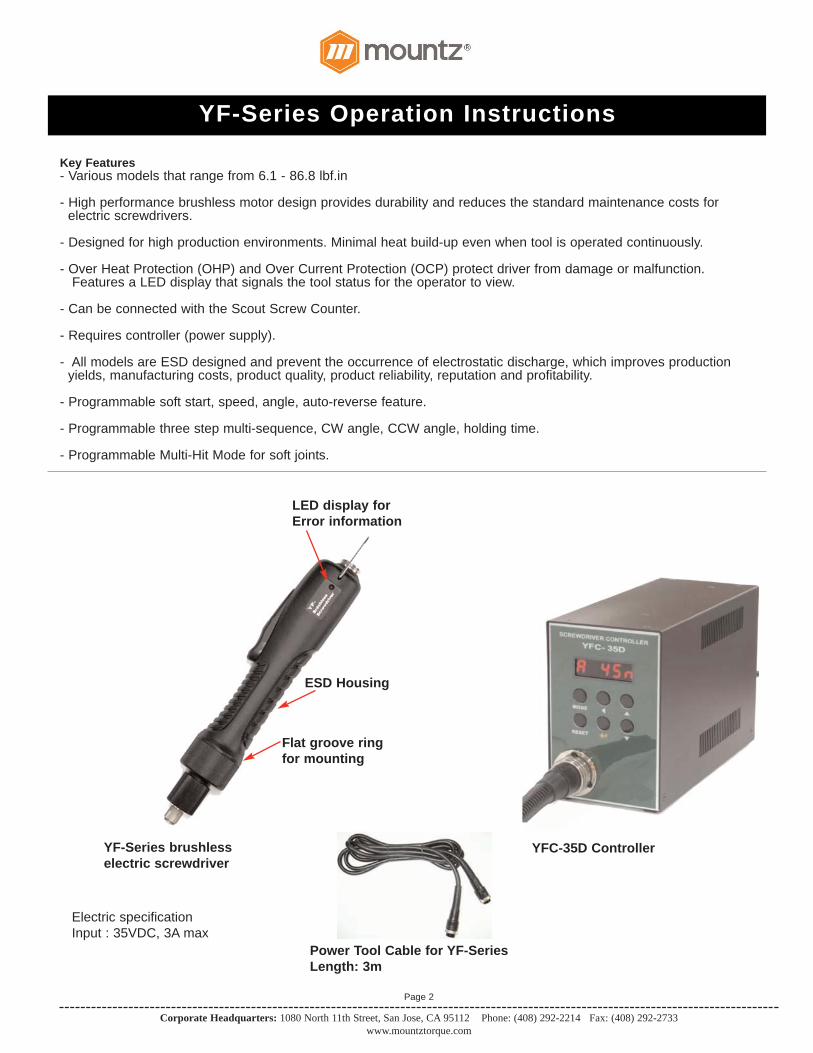
YFC-35D Controller
Power Tool Cable for YF-SeriesLength: 3m
ESD Housing
LED display forError information
Flat groove ringfor mounting
YF-Series brushless electric screwdriver
Electric specificationInput : 35VDC, 3A max

YF-Series Operation Instructions
Corporate Headquarters: 1080 North 11th Street, San Jose, CA 95112 Phone: (408) 292-2214 Fax: (408) 292-2733www.mountztorque.com
Page 3
Alarm display by LED
General Operation for YF-Series models1. Attach power tool cable to the YF screwdriver and YFC-35D Controller. Make sure notch in plug lines up with
the notch on the socket. Tighten knurled ground ring.2. Plug in power cord to the back of the YFC-35D Controller and power outlet. Flip power switch to “ON” position
located on the back of controller.4. Select a bit. Retract the bit collar. Insert the bit and release the retracted collar. To avoid damaging
fasteners, make sure the proper bit is suitable for the head of the fastener.5. The torque limit is determined by the tension of the coil spring housed in the torque adjustment nut. The tighter the
coil spring is wound the higher the torque limit is raised. See Torque Charts on page 10 to determine the appropriate torque adjustment setting.
6. Rotate the torque adjustment nut to set the torque limit. Turn clockwise to increase torque and counter clockwise to decrease torque. The scale adjacent to the Torque Adjustment Nut is a reference guide. The torque output from the driver can change depending on various fastening factors like friction, type of joint, and the type material being used like a washer. Verify torque setting with a torque testing system.
7. Turn driver on and check for proper rotation. FOR-clockwise, REV-counterclockwise.8. To apply torque, squeeze the lever (Push-to-Start models - place light downward pressure on the nose of the driver).
The driver will automatically stop when the preset torque has been reached. 9. To remove the screw, turn the FOR/REV switch to REV position.
torque adjustment nut
LED display
Ø 4
6.6m
m
224mm
163.
5mm
Dimensions: for PYF35N, PYF50N, PYF100N
YF-Series Operation Instructions
Corporate Headquarters: 1080 North 11th Street, San Jose, CA 95112 Phone: (408) 292-2214 Fax: (408) 292-2733www.mountztorque.com
Page 4
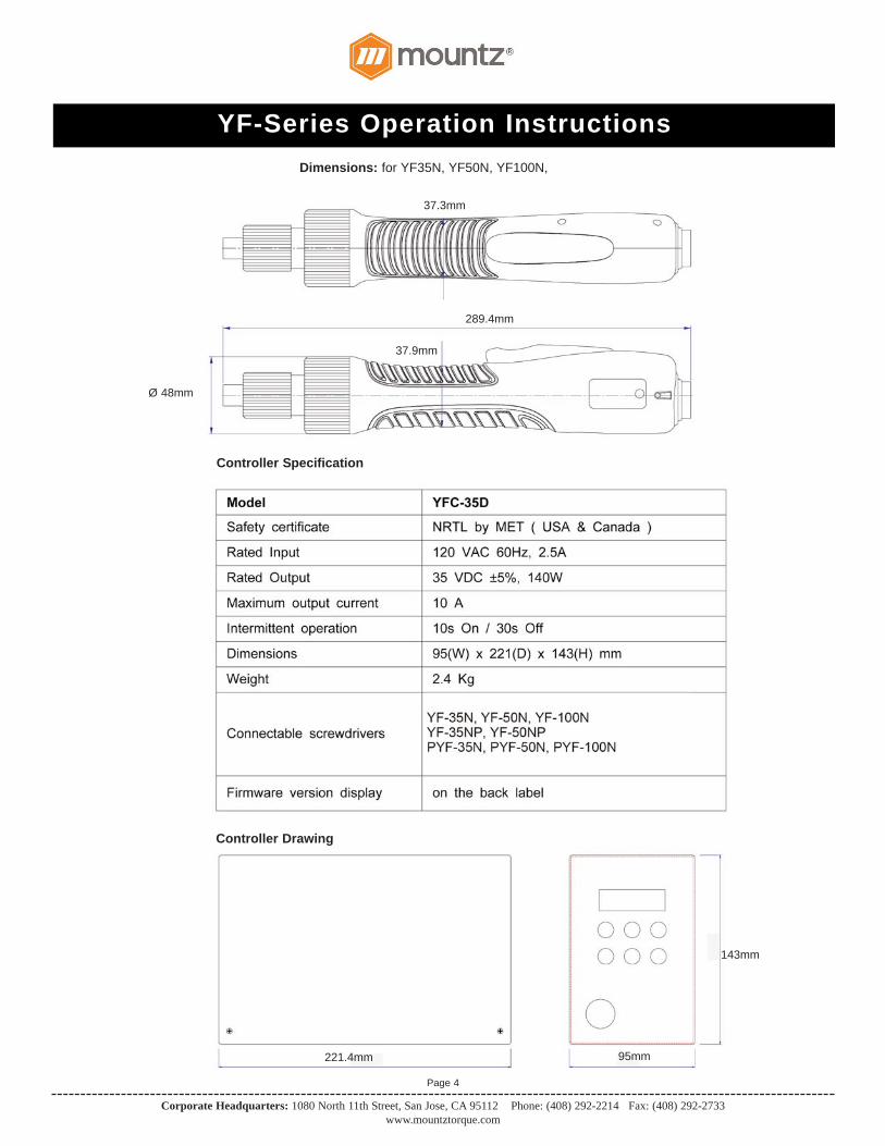
37.3mm
289.4mm
37.9mm
Ø 48mm
95mm
143mm
221.4mm
Controller Specification
Controller Drawing
Dimensions: for YF35N, YF50N, YF100N,

YF-Series Operation Instructions
Corporate Headquarters: 1080 North 11th Street, San Jose, CA 95112 Phone: (408) 292-2214 Fax: (408) 292-2733www.mountztorque.com
Page 5
Operation (Button Functions for the Controller)
Over Current Protection (Overload), Over Heat Protection Details
There are 4 Modes that can be selected.
A Mode setting can be selected by pressing the MODE button. A password is required before being able to make a change. Thecontroller rotates through each Mode option (Auto, Log-in, Parameter and Jog). Auto means operational mode for the tool. Once aMode is selected, the Mode setting will stay active until the controller is powered OFF. All settings are possible in the Parametermode.

YF-Series Operation Instructions
Corporate Headquarters: 1080 North 11th Street, San Jose, CA 95112 Phone: (408) 292-2214 Fax: (408) 292-2733www.mountztorque.com
Page 6
Log-in Mode: Log-in is required for accessing parameter setting. Initial password is "0". It can be changed on PYORD (in Parameter Setting).
Parameter Mode: Cursor shift up to left at the Parameter mode.
Auto (Work) Mode: Select the next preset number.
Log-in & Password: Increase the number up.
Auto (Operation) Mode: Time FND Display DescriptionInitial 0A000 Initial display at the Auto (Work) mode
1st t Display the temperature of driver inside(unit : 0.1°C)
2nd F The latest Fastening time (unit: mS)
3rd L The latest Loosening time (unit: mS)
4th Pc The latest current value ( unit : 0.1A )
5th tu The latest Fastening turns (unit: 0.1 turn)
6th SF Lo Status of Start & Torque up sensor(F:off, o:on) Initial status : SF LF
7th r 0 Real-time rotation speed
Parameter Mode: Decrease the number down.
Jog Mode: Manual stop by button.
Parameter Mode: Select or save the chosen display.
Jog Mode: Manual start by button.
Returns to the previous mode. Also it resets the error.
Operation (Button Functions for the Controller) - Continued
YF-Series Operation Instructions
Corporate Headquarters: 1080 North 11th Street, San Jose, CA 95112 Phone: (408) 292-2214 Fax: (408) 292-2733www.mountztorque.com
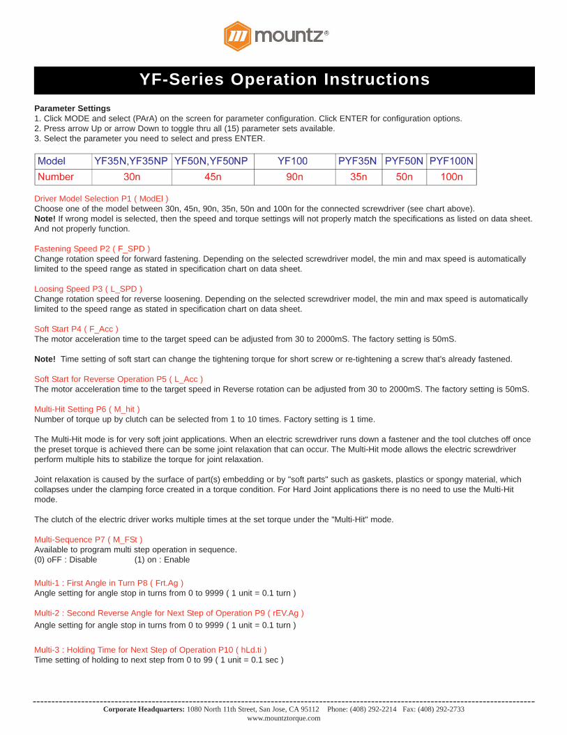
Parameter Settings1. Click MODE and select (PArA) on the screen for parameter configuration. Click ENTER for configuration options.2. Press arrow Up or arrow Down to toggle thru all (15) parameter sets available.3. Select the parameter you need to select and press ENTER.
Driver Model Selection P1 ( ModEl )Choose one of the model between 30n, 45n, 90n, 35n, 50n and 100n for the connected screwdriver (see chart above).Note! If wrong model is selected, then the speed and torque settings will not properly match the specifications as listed on data sheet.And not properly function.
Fastening Speed P2 ( F_SPD )Change rotation speed for forward fastening. Depending on the selected screwdriver model, the min and max speed is automaticallylimited to the speed range as stated in specification chart on data sheet.
Loosing Speed P3 ( L_SPD )Change rotation speed for reverse loosening. Depending on the selected screwdriver model, the min and max speed is automaticallylimited to the speed range as stated in specification chart on data sheet.
Soft Start P4 ( F_Acc )The motor acceleration time to the target speed can be adjusted from 30 to 2000mS. The factory setting is 50mS.
Note! Time setting of soft start can change the tightening torque for short screw or re-tightening a screw that’s already fastened.
Soft Start for Reverse Operation P5 ( L_Acc )The motor acceleration time to the target speed in Reverse rotation can be adjusted from 30 to 2000mS. The factory setting is 50mS.
Multi-Hit Setting P6 ( M_hit )Number of torque up by clutch can be selected from 1 to 10 times. Factory setting is 1 time.
The Multi-Hit mode is for very soft joint applications. When an electric screwdriver runs down a fastener and the tool clutches off oncethe preset torque is achieved there can be some joint relaxation that can occur. The Multi-Hit mode allows the electric screwdriverperform multiple hits to stabilize the torque for joint relaxation.
Joint relaxation is caused by the surface of part(s) embedding or by "soft parts" such as gaskets, plastics or spongy material, which collapses under the clamping force created in a torque condition. For Hard Joint applications there is no need to use the Multi-Hit mode.
The clutch of the electric driver works multiple times at the set torque under the "Multi-Hit" mode.
Multi-Sequence P7 ( M_FSt )Available to program multi step operation in sequence.(0) oFF : Disable (1) on : Enable
Multi-1 : First Angle in Turn P8 ( Frt.Ag )Angle setting for angle stop in turns from 0 to 9999 ( 1 unit = 0.1 turn )
Multi-2 : Second Reverse Angle for Next Step of Operation P9 ( rEV.Ag )Angle setting for angle stop in turns from 0 to 9999 ( 1 unit = 0.1 turn )
Multi-3 : Holding Time for Next Step of Operation P10 ( hLd.ti )Time setting of holding to next step from 0 to 99 ( 1 unit = 0.1 sec )

YF-Series Operation Instructions
Corporate Headquarters: 1080 North 11th Street, San Jose, CA 95112 Phone: (408) 292-2214 Fax: (408) 292-2733www.mountztorque.com
Page 8
Parameter Settings (Continued)
Display setting P11 ( dSP.Md )Display setting between two:0: number of speed setting 1 : real time speed
External I/O for Remote Control P12 ( PLc.Md )Available to use I/O for remote control.0 oFF : Disable 1 on : Enable
Reverse torque control setting P13 ( REvMd )Reverse torque control can be selected between ON/OFF . Factory setting password is "on”on : Stop by torque up off : Slip
Password Setting P14 ( PYord )Setting new password. Factory setting password is " 0 "
Parameter Initialization to Factory Setting P15 ( Pinit )All parameter will be changed to it's original torque setting. Password is "77"
Firmware version display P16 ( VEr )
I/O Details (Porting Options)

YF-Series Operation Instructions
Corporate Headquarters: 1080 North 11th Street, San Jose, CA 95112 Phone: (408) 292-2214 Fax: (408) 292-2733www.mountztorque.com
Page 9
I/O Interface Port Details (Back Panel)
I/O Interface Connection Details
YF-Series Operation Instructions
Corporate Headquarters: 1080 North 11th Street, San Jose, CA 95112 Phone: (408) 292-2214 Fax: (408) 292-2733www.mountztorque.com
Page 10
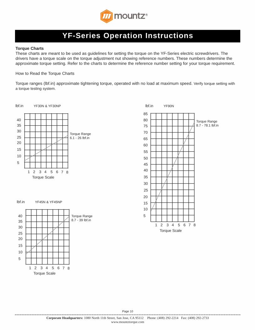
Torque ChartsThese charts are meant to be used as guidelines for setting the torque on the YF-Series electric screwdrivers. Thedrivers have a torque scale on the torque adjustment nut showing reference numbers. These numbers determine theapproximate torque setting. Refer to the charts to determine the reference number setting for your torque requirement.
How to Read the Torque Charts
Torque ranges (lbf.in) approximate tightening torque, operated with no load at maximum speed. Verify torque setting witha torque testing system.
YF30N & YF30NPlbf.in
Torque Range6.1 - 26 lbf.in
1 2 3 4 5 6Torque Scale
5
10
15
20253035
7 8
YF90N lbf.in
Torque Range8.7 - 78.1 lbf.in
1 2 3 4 5 6Torque Scale
7 8
40
YF45N & YF45NPlbf.in
Torque Range8.7 - 39 lbf.in
1 2 3 4 5 6Torque Scale
5
10
15
20253035
7 8
40
25
30
35
404550
55
60
65
70
758085
20
1510
5

YF-Series Operation Instructions
Corporate Headquarters: 1080 North 11th Street, San Jose, CA 95112 Phone: (408) 292-2214 Fax: (408) 292-2733www.mountztorque.com
Page 11
Torque ChartsThese charts are meant to be used as guidelines for setting the torque on the YF-Series electric screwdrivers. Thedrivers have a torque scale on the torque adjustment nut showing reference numbers. These numbers determine theapproximate torque setting. Refer to the charts to determine the reference number setting for your torque requirement.
How to Read the Torque Charts
Torque ranges (lbf.in) approximate tightening torque, operated with no load at maximum speed. Verify torque setting witha torque testing system.
PYF35Nlbf.in
Torque Range6.1 - 43.4 lbf.in
1 2 3 4 5 6Torque Scale
5
10
15
20253035
7 8
PYF100N lbf.in
Torque Range8.7 - 87 lbf.in
1 2 3 4 5 6Torque Scale
7 8
40
PYF50Nlbf.in
Torque Range8.7 - 39 lbf.in
1 2 3 4 5 6Torque Scale
5
10
15
20253035
7 8
40
25
30
35
404550
55
60
65
70
758085
20
1510
5
90
YF-Series Operation Instructions
Corporate Headquarters: 1080 North 11th Street, San Jose, CA 95112 Phone: (408) 292-2214 Fax: (408) 292-2733www.mountztorque.com
Page 12
The EZ-Glider torque arms are designed to improve production and quality control during the assemblyprocess. The arms securely keep electric or pneumatic drivers in perpendicular alignment to help preventside loading or cross threading occurring during the assembly process. The EZ-Glider helps remove theoperator’s influence in the assembly process and strengthens quality control.
The ergonomic design of the EZ-Glider torque arms reduces RMI (repetitive motion injury) and CTS(carpal tunnel syndrome). The effortless handling of the torque arm provides comfortable tool operationand increased production. The torque arm can be installed in space-restricted areas
Accessories
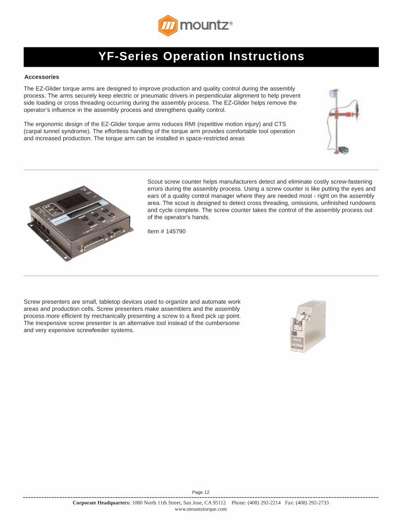
Scout screw counter helps manufacturers detect and eliminate costly screw-fasteningerrors during the assembly process. Using a screw counter is like putting the eyes andears of a quality control manager where they are needed most - right on the assemblyarea. The scout is designed to detect cross threading, omissions, unfinished rundownsand cycle complete. The screw counter takes the control of the assembly process outof the operator's hands.
Item # 145790
Screw presenters are small, tabletop devices used to organize and automate workareas and production cells. Screw presenters make assemblers and the assemblyprocess more efficient by mechanically presenting a screw to a fixed pick up point.The inexpensive screw presenter is an alternative tool instead of the cumbersomeand very expensive screwfeeder systems.

YF-Series Operation Instructions
Corporate Headquarters: 1080 North 11th Street, San Jose, CA 95112 Phone: (408) 292-2214 Fax: (408) 292-2733www.mountztorque.com
RPM for Electric Screwdrivers
Models RPM AdjustableYF35N-A ESD 500-1500YF35NP-A ESD 500-1500PYF35NP-A ESD 500-1500YF50N-A ESD 400-1100YF50NP-A ESD 400-1100PYF50NP-A ESD 400-1100YF100N-A ESD 250-500PYF100NP-A ESD 250-500
Testing Power Tools: 1. Application Method: Use a torque analyzer in “Peak Mode” with a rotary transducer between the power tool and the actual
application. This is the best way to test since you are using the actual joint as the test station. You will see the actual torque applied to the fastener. Caution: Variances in tool performance may occur do to the addition of the rotary transducer.
2. Simulated Method: Always use a quality joint rate simulator (run down adapter) with a torque analyzer when testing power tools in a simulated application. Use Joint rate and Breakaway methods to obtain most accurate torque readings in a simulated rundown.
Care1. The YF-Series screwdrivers are a precision torque control instrument and should be handled with care at all times.2. Only use the controller listed in the Mountz catalog or website for appropriate YF-Series driver model (If you have any questions
regarding the appropriate controller set-up, contact Mountz Customer Service Department).3. Operate under safe conditions. Do not place in operation where such objects as hair, strings, clothing, etc. can become
tangled in the rotating bit. 4. Keep away from moisture. Never use in high humid, moist or damp
environment.
ServiceMountz Inc. features an experienced calibration and repair staff. Our trained technicians can calibrate and repair most any tool.Mountz provides rapid service with quality that you can trust as we offer three state-of-the-art calibration lab and repair facilities thatcan calibrate up to 20,000 lbf.ft.
Mountz, The Torque Tool Specialists®, has been a leader in the torque tool industry for more than 50 years. Engineered in the SiliconValley and serving the globe, Mountz focuses on delivering high-quality torque products, services, and solutions to ensure customerscan always proceed with confidence. We are committed to forging a safer worldthrough precision and accuracy, and by innovating every day.
Tool Service & Repair CapabilityTorque Wrenches: Click, Dial, Beam, Cam-Over & Break-Over
Torque Screwdrivers: Dial, Micrometer, Preset & Adjustable
Torque Analyzers/Sensors: All brands
Electric Screwdrivers: All brands
Air Tools: All brandsImpact Wrenches, Drills, Pulse Tools, Grinders, Percussive Tools, Air Screwdrivers, Nutrunners, DC Controlled Nutrunners
Torque Multipliers: All brands
Page 13
Mountz Service LocationsEastern Service Center19051 Underwood Rd.
Foley, AL 36535Phone: (251) 943-4125
Fax: (251) 943-4979
Western Service Center1080 N.11th Street
San Jose, CA 95112Phone: (408) 292-2214
Fax: (408) 292-2733