yk - all modelsyork.ru.com/files/inzhenepnoe_rykovodstvo_yk.pdf · engineering guide yk - all...
TRANSCRIPT

ENGINEERING GUIDE
YK - ALL MODELS
Revision 0 Form 160.75-EG1.EN.CE/PED (1210)
CENTRIFUGAL LIQUID CHILLERSTYLE G (879 - 10,500 KW)
R134a

2
Form No. 160.75-EG1.EN.CE/PED (1210)
NOMENCLATURE YK ER ER Q7 5 CS G S
Special Fea turesModel Design Level Evaporator Code Motor Code Condenser Code Power Supply Compressor Code 5 for 50 Hz
Introduction ........................................................ 3Ratings .............................................................. 4OptiView Control Center .................................... 5Mechanical Specifi cations ................................. 8Accessories and Modifi cations ........................ 12Application Data .............................................. 14Dimensions (mm) - Unit ................................. 24Dimensions (mm) - Nozzle Arrangements ..... 27Weights ........................................................... 38
TABLE OF CONTENTS

3
Form No. 160.75-EG1.EN.CE/PED (1210)
INTRODUCTION
YORK YK Chillers offer a complete combination of features for total owner satisfaction.
MATCHED COMPONENTS MAXIMIZE EFFICIENCY
Actual chiller effi ciency cannot be determined by analyzing the theoretical effi ciency of any one chiller component. It requires a specifi c combination of heat exchanger, compressor, and motor performance to achieve the lowest system kW/kW. YORK chiller technology matches chiller system components to provide maximum chiller effi ciency under actual – not just theoretical – operating conditions.
REAL-WORLD ENERGY PERFORMANCE
Johnson Controls pioneered the term “Real-World Energy” to illustrate the energy-saving potential of focusing on chiller performance during off-design conditions. Off-design is not only part load, but full load operation as well, with reduced entering condenser water temperatures (ECWTs). This is where chillers operate 99% of the time, and where operating costs add up.
The YK chillers are the only chillers designed to operate on a continuous basis with cold ECWT and full condenser fl ow at all load points, taking full advantage of Real-World conditions. This type of operation benefi ts the cooling tower as well; reducing cycling of the fan motor and ensuring good coverage of the cooling fi ll.
YORK YK chillers offer the most effi cient Real-World operation of any chiller, meaning lower operating costs and an excellent return on your chiller investment.
OPEN-DRIVE DESIGN
Hermetic motor burnout can cause catastrophic damage to a chiller. The entire chiller must be cleaned, and the refrigerant replaced. YORK YK centrifugal chillers eliminate this risk by utilizing air-cooled motors. Refrigerant never comes in contact with the motor, preventing contamination of the rest of the chiller.
Insurance companies that offer policies on large air conditioning equipment often consider air-cooled motors a signifi cant advantage over hermetic refrigerant-cooled units.
HIGH EFFICIENCY HEAT EXCHANGERS
YK chiller heat exchangers offer the latest technology in heat transfer surface design to give you maximum effi ciency and compact design. Waterside and refrigerant side design enhancements minimize both energy consumption and tube fouling.
SINGLE STAGE COMPRESSOR DESIGN AND EFFICIENCY PROVEN IN THE MOST DEMANDING APPLICATIONS
Designed to be the most reliable chillers we’ve ever made, YORK YK centrifugal chillers incorporate single-stage compressor design. With fewer moving parts and straightforward, effi cient engineering, YORK single-stage compressors have proven durability records in hospitals, chemical plants, gas processing plants, the U.S. Navy, and in other applications where minimal downtime is a crucial concern.
In thousands of installations worldwide, YORK single-stage compressors are working to reduce energy costs. High strength aluminum-alloy compressor impellers feature backward curved vanes for high effi ciency. Airfoil shaped pre rotation vanes minimize fl ow disruption for the most effi cient part load performance. Precisely positioned and tightly fi tted, they allow the compressor to unload smoothly from 100% to minimum load for excellent operation in air conditioning applications.
PRECISION CONTROL OF COMPRESSOR OIL PRESSURE
Utilizing our expertise in variable speed drive technology and applications, Johnson Controls has moved beyond the fi xed head and bypass approach of oil pressure control. The old approach only assures oil pressure at the outlet of the pump rather than at the compressor, and allows no adjustment during chiller operation. The YK chillers feature a variable speed drive oil pump, monitoring and providing the right amount of oil fl ow to the compressor on a continuous basis. This design also provides sophisticated electronic monitoring and protection of the oil pump electrical supply, ensuring long life and reliable operation of the oil pump motor. Variable speed drive technology reduces oil pump power consumption, running only at the speed required, rather than at full head with a pressure regulating bypass valve.
FACTORY PACKAGING REDUCES FIELD LABOUR COSTS
YORK YK centrifugal chillers are designed to keep installation costs low. Where installation access is not a problem, the unit can be shipped completely packaged, requiring minimal piping and wiring to complete the installation.
For those units utilizing Variable Speed Drive or a factory-installed Solid-State Starter, the three power leads provide all power to the chiller and its auxiliaries.

4
Form No. 160.75-EG1.EN.CE/PED (1210)
RATINGS
TAKE ADVANTAGE OF COLDER COOLING TOWER WATER TEMPERATURES
YORK YK centrifugal chillers have been designed to take full advantage of colder cooling tower water temperatures, which are naturally available during most operating hours. Considerable energy savings are available by letting tower water temperature drop, rather than artifi cially holding it above 23.9°C, especially at low load, as some chillers require.
SPECIFICATION
YK chillers are designed within EN ISO 9001 and built within an EN ISO 9002 accredited manufacturing organisation.
Chillers conform with the following European Directives:
• Machinery directive (2006/42/EC)
• EMC Directive (2004/108/EC)
• Pressure Equipment Directive (97/23/EC)
• Safety Code for Mechanical Refrigeration(EN378-2 (2008))
COMPUTERIZED PERFORMANCE RATINGS
Each chiller is custom-matched to meet the individual building load and energy requirements. A variety of standard heat exchangers and pass arrangements are available to provide the best possible match.
It is not practical to provide tabulated performance for each combination, as the energy requirements at both full and part load vary signifi cantly with each heat exchanger and pass arrangement. Computerized ratings are available through each Johnson Controls sales offi ce. These ratings can be tailored to specifi c job requirements.
OFF-DESIGN PERFORMANCE
Since the vast majority of its operating hours are spent at off-design conditions, a chiller should be chosen not only to meet the full load design, but also for its ability to perform effi ciently at lower loads and lower tower water temperatures. It is not uncommon for chillers with the same full load kW to have an operating cost difference of over 10% due to part-load operation.
Part load information can be easily and accurately generated by use of the computer. And because it is so important to an owner’s operating budget, this information has now been standardized.
A more detailed analysis must take into account actual building load profi les, and local weather data. Part load performance data should be obtained for each job using its own design criteria.

5
Form No. 160.75-EG1.EN.CE/PED (1210)
OPTIVIEW CONTROL CENTER
YK OPTIVIEW CONTROL CENTER
The YORK OptiView™ Control Center, furnished as standard on each chiller, provides the ultimate in effi ciency, monitoring, data recording, chiller protection and operating ease. The Control Center is a factory-mounted, wired and tested state-of-the-art microprocessor based control system for R134a centrifugal chillers. The panel is confi gured with a 10.4-in. (264 mm) diagonal color Liquid Crystal Display (LCD) surrounded by “soft” keys, which are redefi ned with one keystroke based on the screen displayed at that time. This revolutionary development makes chiller operation quicker and easier than ever before. Instead of requiring keystroke after keystroke to hunt for information on a small monochrome LCD screen, a single button reveals a wide array of information on a large, full-color illustration of the appropriate component, which makes information easier to interpret. This is all mounted in the middle of a keypad interface and installed in a locked enclosure.
The LCD display allows graphic animated display of the chiller, chiller sub-systems and system parameters; this allows the presentation of several operating parameters at once. In addition, the operator may view a graphical representation of the historical operation of the chiller as well as the present operation. A Status Bar is displayed at all times on all screens. It contains the System - Status Line and Details Line, the Control Source, Access Level, Time and Date.
During pre-lube and coast-down, the system status will include a countdown timer indicating the time remaining. The control panel is compatible with the YORK Solid-State Starter (optional); YORK Variable Speed Drive (VSD) (Optional); Electro-mechanical (E-M) starter or any customer supplied E-M starter that complies with the YORK R-1132 standard. The locations of various chiller parameters are clearly marked and instructions
for specifi c operations are provided for on many of
the screens. The panel verbiage is available in eight languages as standard and can be changed on the fl y without having to turn off the chiller. Data can be displayed in either English or Metric units plus keypad entry of setpoints to 0.1 increments.
Security access is provided to prevent unauthorized changes of setpoints. This is accomplished with three different levels of access and passwords for each level. There are certain screens, displayed values, Programmable setpoints and manual controls not shown that are for servicing the chiller. They are only displayed when logged in at service access level. Included in this is the Advanced Diagnostics and troubleshooting information for the chiller and the panel.
The panel is fused through a 1.5 or 2 KVA transformer in the compressor motor starter to provide individual over-current protected power for all controls. Numbered terminal strips for wiring such as Remote Start/Stop, Flow Switches, Chilled Water Pump and Local or Remote Cycling devices are provided. The Panel also provides fi eld interlocks that indicate the chiller status. These contacts include a Remote Mode Ready-to-Start, a Cycling Shutdown, a Safety Shutdown and a chiller Run contact. Pressure transducers sense system pressures and thermistors sense system temperatures. The output of each transducer is a DC voltage that is analogous to the pressure input. The output of each thermistor is a DC voltage that is analogous to the temperature it is sensing.
Setpoints can be changed from a remote location via 0-10VDC, 4-20mA, contact closures or through serial communications. The adjustable remote reset range 11.1°C provides fl exible, effi cient use of remote signal depending on reset needs. Serial data interface to the Building Automation System (BAS) is through the optional microgateway, which can be mounted inside the Control Center.

6
Form No. 160.75-EG1.EN.CE/PED (1210)
This printed circuit board requests the required data from the microboard and makes it available for the Johnson Controls Metasys® network. This optional board is available through the Johnson Controls Building Effi ciency group. The operating program is stored in non-volatile memory (EPROM) to eliminate chiller failure due to AC power failure/battery discharge. Programmed setpoints are retained in lithium battery-backed RTC memory for 10 years minimum.
Smart Freeze Point Protection will run the chiller at 2.2°C leaving chilled water temperature, and not permit nuisance trips on Low Water Temperature. The sophisticated program and sensor will monitor the chiller water temperature to prevent freeze up. Every Programmable point has a pop-up screen with the allowable ranges, so that the chiller cannot be programmed to operate outside of its design limits.
When the power is applied to the chiller, the HOME screen is displayed. This screen displays a visual representation of the chiller and a collection of data detailing important operations and parameters. When the chiller is running the fl ow of chilled liquid is animated by the alternating shades of color moving in and out of the pipe nozzles. The primary values that need to be monitored and controlled are shown on this screen.
With the “soft” keys the operator is only one touch away from the 8 main screens that allows access to the major information and components of the chiller. The 8 screens are the SYSTEM, EVAPORATOR, CONDENSER, COMPRESSOR, OIL SUMP, MOTOR, SETPOINTS and the HISTORY. Also on the Home screen is the ability to Log IN, Log Out and Print. Log In and Log Out is the means by which different security levels are accessed.
The SYSTEM screen gives a general overview of common chiller parameters for both shells. This is an end view of the chiller with a 3D cutaway of both the shells.
The EVAPORATOR screen displays a cutaway view of the chiller evaporator. All setpoints relating to the evaporator side of the chiller are maintained on this screen. Animation of the evaporation process indicates whether the chiller is presently in RUN condition (bubbling) and liquid fl ow in the pipes is indicated by alternating shades of color moving in and out of the pipes. Adjustable limits on the low water temperature setpoints allow the chiller to cycle on and off for greater effi ciency and less chiller cycling. The chiller cycles off when the leaving chilled water temperature is below the setpoint and is adjustable from 0.55°C below to a minimum of 2.2°C. Restart is adjustable from the setpoint up to a max of 44.4°C. The panel will check for fl ow to avoid freeze up of the tubes. If fl ow is interrupted shutdown will occur after a minimum of two seconds.
The CONDENSER screen displays a cutaway view of the chiller condenser. The liquid fl ow is animated to indicate fl ow through the condenser. All setpoints relating to the condenser side of the chiller are maintained on this screen. With the proper access level, this screen also serves as a gateway to controlling the Refrigerant Level.
HEAT RECOVERY
The HEAT RECOVERY screen displays a cutaway view of the chiller condenser. The liquid fl ow is animated to indicate fl ow when there is fl ow in either the lower tower bundle or upper heating bundle. All setpoints relating to the upper heating bundle are maintained on this screen.
The COMPRESSOR screen displays a cutaway view of the compressor; this reveals the impeller and shows all the conditions associated with the compressor. When the compressor impeller is spinning this indicates that the chiller is presently in RUN condition. With the proper access level, the pre-rotation vanes may be manually controlled. This screen also serves as a gateway to sub-screens for calibrating the pre-rotation vanes, the proximity probe, confi guring the Hot Gas Bypass, or providing advanced control of the compressor motor Variable Speed Drive.
The OIL SUMP screen displays a close-up view of the chiller oil sump and provides all the necessary setpoints for maintaining the Variable Speed Oil Pump (VSOP). This screen also allows manual control of the frequency command sent to the VSOP.
The MOTOR “soft” key on the Home screen when pressed shows a picture of a YORK Electro-Mechanical Starter, Solid-State Starter or a Variable Speed Drive Screen depending on chiller confi guration. Programmable pulldown demand to automatically limit motor loading for minimizing building demand charges is provided. Pulldown time period control over four hours, and verifi cation of time remaining in pulldown cycle from display readout. Separate digital setpoint for current limiting between 30 and 100%.
The ELECTRO-MECHANICAL STARTER – (E-M) screen displays a picture of the starter and additional values.
The SOLID STATE STARTER – (SSS) screen displays a picture of the starter and additional values.
The VARIABLE SPEED DRIVE - (VSD) screen displays a picture of the VSD and additional values:
There are two additional screens (sub-screens) that have further VSD information.
The SETPOINTS screen provides a convenient location for programming the most common setpoints involved in the chiller control. The Setpoints are shown on other individual screens but to cut down on needless searching they are on this one screen. This screen also serves as a gateway to a sub-screen for defi ning the setup of general system parameters.
The SETUP is the top level of the general confi guration parameters. It allows programming of the time and date, along with specifi cations as to how the time will be displayed. In addition, the chiller confi guration as determined by the microboard program jumpers and program switches is displayed. From this screen you can perform the following:
The following 6 sub-screens can be accessed from the setup screen:

7
Form No. 160.75-EG1.EN.CE/PED (1210)
The SCHEDULE screen contains more programmable values than a normal display screen. Each programmable value is not linked to a specifi c button; instead the select key is used to enable the cursor arrows and check key to program the Start/Stop times for any day of the week up to 6 weeks in advance. The user has the ability to defi ne a standard set of Start/Stop times that are utilized every week or specify exceptions to create a special week.
The USER screen allows defi nition of the language for the chiller to display and defi nes the unit of measure.
The COMMS screen allows defi nition of the necessary communications parameters.
The PRINTER screen allows Defi nition of the necessary communications Parameters for the printer.
The SALES ORDER screen allows defi nition of the order parameters.
The OPERATIONS screen allows defi nition of parameters related to the operation of the chiller. What is defi ned is whether the control of the chiller will be Local, Digital Remote, Analog Remote, Modem Remote or Metasys™ Remote.
The HISTORY screen allows the user to browse through the last ten faults; either safety or cycling shutdowns with the conditions while the chiller is running or stopped. The faults are color coded for ease in determining the severity at a glance, recording the date, time and description. (See Display Messages for Color Code meanings.)
By pressing the VIEW DETAILS key you will move to the HISTORY DETAILS screen. From these screens you are able to see an on-screen printout of all the system parameters at the time of the selected shutdown.
Also under the History screen is the TRENDING screen, accessible by the key marked the same. On this screen up to six operator-selected parameters, selected from a list of over 140, can be plotted in an X/Y graph format, The graph can be customized to record points once every second up to once every hour. There are two types of charts that can be created: a single or continuous screen. The single screen collects data for one screen width (450 data points across the x-axis) then stops. The continuous screen keeps collecting the data but the oldest data drops off the graph from left to right at the next data collection interval. For ease of identifi cation, each plotted parameter, title and associated Y- axis labeling is color coordinated.
The TREND SETUP screen is used to confi gure the trending screen. The parameters to be trended are selected from the Trend Common Slots Screen accessed from the Slot #s button or the Master Slot Numbers List found in the operating manual. The interval at which all the parameters are sampled is selected under the Collection Interval button. The data point min. and max. values may be adjusted closer within the range to increase viewing resolution.
The TREND COMMON SLOTS screen displays the Master Slot Numbers List of the monitored parameters.
DISPLAY MESSAGES
The Control Center continually monitors the operating system displaying and recording the cause of any shutdowns (Safety, Cycling or Normal). The condition of the chiller is displayed at the System Status line that contains a message describing the operating state of the chiller; whether it is stopped, running, starting or shutting down. A System Details line displays Warning, Cycling, Safety, Start Inhibit and other messages that provide further details of Status Bar messages. Messages are color-coded: Green – Normal Operations, Yellow - Warnings, Orange – Cycling Shutdowns, and Red – Safety Shutdowns to aid in identifying problems quickly.

8
Form No. 160.75-EG1.EN.CE/PED (1210)
MECHANICAL SPECIFICATIONS
GENERAL
The YORK YK Centrifugal Liquid Chillers are completely factory-packaged including the evaporator, condenser, compressor, motor, lubrication system, control center, and all interconnecting unit piping and wiring.
The initial charge of refrigerant and oil is supplied for each chiller. When the optional condenser isolation valves are ordered, most units may ship fully charged with refrigerant and oil. Actual shipping procedures will depend on a number of project-specifi c details.
The services of a Johnson Controls factory-trained, fi eld service representative are incurred to supervise or perform the fi nal leak testing, charging, the initial start-up, and concurrent operator instructions.
COMPRESSOR
The compressor is a single stage centrifugal type powered by an open drive electric motor. The casing is fully accessible with vertical circular joints and fabricated of close grain cast iron. The complete operating assembly is removable from the compressor and scroll housing.
The rotor assembly consists of a heat treated alloy steel drive shaft and impeller shaft with a high strength, cast aluminum alloy, fully shrouded impeller. The impeller is designed for balanced thrust and is dynamically balanced and overspeed tested for smooth, vibration free operation.
The insert-type journal and thrust bearings are fabricated of aluminum alloy and are precision bored and axially grooved. The specially engineered, single helical gears with crowned teeth are designed so that more than one tooth is in contact at all times to provide even distribution of compressor load and quiet operation. Gears are assembled as part of the compressor rotor support and are fi lm lubricated. Each gear is individually mounted in its own journal and thrust bearings to isolate it from impeller and motor forces.
CAPACITY CONTROL
Pre-rotation vanes (PRV) modulate chiller capacity from 100% to 15% of design for normal air conditioning applications. Operation is by an external, electric PRV actuator which automatically controls the vane position to maintain a constant leaving chilled liquid temperature. Rugged airfoil-shaped, cast-manganese-bronze vanes are precisely positioned by solid vane linkages connected to the electric actuator.
LUBRICATION SYSTEM
Lubrication oil is force-fed to all bearings, gears and rotating surfaces by a variable speed drive pump which operates prior to startup, continuously during operation and during coastdown. A gravity fed oil reservoir is built into the top of the compressor to provide lubrication during coastdown in the event of a power failure.
An oil reservoir, separate from the compressor, contains the submersible oil pump, 1.5 kW pump motor and 3000 watt immersion type oil heater. The oil heater is thermostatically controlled to remove refrigerant from the oil.
Oil is fi ltered by an externally mounted 1/2 micron replaceable cartridge oil fi lter equipped with service valves. Oil is cooled via a refrigerant-cooled oil cooler, eliminating the requirement for fi eld water piping. The oil side of the oil cooler is provided with service valves. An automatic oil return system recovers any oil that may have migrated to the evaporator. Oil piping is completely factory-installed.
WATER-COOLED OIL COOLER
Optional condenser water-cooled oil cooler is offered for units with Q3 compressors C-D shells only. This oil cooler is a shell and tube heat exchanger. Water from condenser supply waterbox circulates through the tube side of the heat exchanger and discharges back into the return side of the waterbox. Hot oil circulates through the tubes within the oil cooler, and is cooled by the cold condenser water. The cooled oil is then sent back to the compressor through a temperature regulator valve and oil fi lters. Both the oil and water piping are completely factory-installed, eliminating the requirement for fi eld piping.
MOTOR DRIVELINE
The compressor motor is an open drip proof, squirrel cage, induction type constructed to YORK design specifi cations.
The open motor is provided with a D fl ange, and is factory-mounted to a cast iron adaptor mounted on the compressor. This unique design allows the motor to be rigidly coupled to the compressor to provide factory alignment of motor and compressor shafts.
Motor drive shaft is directly connected to the compressor shaft with a fl exible disc coupling. Coupling has all metal construction with no wearing parts to assure long life, and no lubrication requirements to provide low maintenance.
For units utilizing remote electro mechanical starters, a large, steel terminal box with gasketed front access cover is provided for fi eld-connected conduit. There are six terminals (three for medium voltage) brought through the motor casing into the terminal box. Jumpers are furnished for three-lead types of starting. Motor terminal lugs are not furnished. Overload/over-current transformers are furnished with all units. For units furnished with factory-packaged Solid-State Starters or Variable Speed Drive, refer to the Accessories and Modifi cations Section.
HEAT EXCHANGERS
Shells
Evaporator and condenser shells are fabricated from rolled carbon steel plates with fusion welded seams or carbon steel pipe. Carbon steel tube sheets, drilled and reamed to accommodate the tubes, are welded to the end of each shell. Intermediate tube supports are fabricated from carbon steel plates, drilled and reamed to eliminate sharp edges, and spaced no more than four feet apart. The refrigerant side of each shell is designed, tested, and stamped in accordance with the pressure vessel code as appropriate.

9
Form No. 160.75-EG1.EN.CE/PED (1210)
Tubes
Heat exchanger tubes are state-of-the-art, high-effi ciency, externally and internally enhanced type to provide optimum performance. Tubes in both the evaporator and condenser are 19 mm O.D. standard or 25.4 mm optional in some shells] copper alloy and utilize the “skip-fi n” design, providing a smooth internal and external surface at each intermediate tube support. This provides extra wall thickness (up to twice as thick) and non work-hardened copper at the support location, extending the life of the heat exchangers. Each tube is roller expanded into the tube sheets providing a leak-proof seal, and is individually replaceable.
Evaporator
The evaporator is a shell and tube, fl ooded type heat exchanger. A distributor trough provides uniform distribution of refrigerant over the entire shell length to yield optimum heat transfer. A suction baffl e or aluminum mesh eliminators are located above the tube bundle to prevent liquid refrigerant carryover into the compressor. A 38 mm liquid level sight glass is conveniently located on the side of the shell to aid in determining proper refrigerant charge. The evaporator shell contains a dual refrigerant relief valve arrangement set at 12.4 barg on H and K Compressor models; 16.2 barg on P and Q Compressor models; or single-relief valve arrangement, if the chiller is supplied with the optional refrigerant isolation valves. A 25.4 mm refrigerant charging valve is provided.
Condenser
The condenser is a shell and tube type, with a discharge gas baffl e to prevent direct high velocity impingement on the tubes. The baffl e is also used to distribute the refrig¬erant gas fl ow properly for most effi cient heat transfer. An optional cast steel condenser inlet diffuser may be offered, on "M" and larger condensers, in lieu of the baffl e, to provide dynamic pressure recovery and enhanced chiller effi ciency. An integral sub cooler is located at the bottom of the condenser shell providing highly effective liquid refrigerant subcooling to provide the highest cycle effi ciency. The condenser contains dual refrigerant relief valves set at 16.2 barg.
Waterboxes
The removable waterboxes are fabricated of steel. The design working pressure is 10.3 barg and the boxes are tested at 15.5 barg. Integral steel water baffl es are located and welded within the waterbox to provide the required pass arrangements. Water nozzle connections with grooves are welded to the water boxes. These nozzle connections are suitable couplings, welding or fl anges, and are capped for shipment. Plugged 19 mm drain and vent connections are provided in each water box.
WATER FLOW SWITCHES
Thermal type water fl ow switches are factory mounted in the chilled and condenser water nozzles, and are factory wired to the OptiView control panel. These solid state fl ow sensors have a small internal heating-element. They use the cooling effect of the fl owing fl uid to sense when an adequate fl ow rate has been established. The sealed sensor probe is 316 stainless steel, which is suited to very high working pressures.
REFRIGERANT FLOW CONTROL
Refrigerant fl ow to the evaporator is controlled by the YORK variable orifi ce control system. Liquid refrigerant level is continuously monitored to provide optimum subcooler, condenser and evaporator performance. The variable orifi ce electronically adjusts to all Real-World operating conditions, providing the most effi cient and reliable operation of refrigerant fl ow control.
OPTIVIEW CONTROL CENTER
General
The chiller is controlled by a stand-alone microprocessor based control center. The chiller control panel provides control of chiller operation and monitoring of chiller sensors, actuators, relays and switches.
Control Panel
The control panel includes a 10.4-in. (264 mm) diagonal color liquid crystal display (LCD) surrounded by “soft” keys which are redefi ned based on the screen displayed at that time, mounted in the middle of a keypad interface and installed in a locked enclosure. The screen details all operations and parameters, using a graphical representation of the chiller and its major components. Panel verbiage is available in eight languages and can be changed on the fl y without having to turn off the chiller. Data can be displayed in either English or Metric units. Smart Freeze Point Protection will run the chiller at 2.2°C leaving chilled water temperature, and not have nuisance trips on low water temperature. The sophisticated program and sensor monitors the chiller water temperature to prevent freeze-up. When needed, Hot Gas Bypass is available as an option. The panel displays countdown timer messages so the operator knows when functions are starting and stopping. Every programmable point has a pop-up screen with the allowable ranges, so that the chiller cannot be programmed to operate outside of its design limits.
The chiller control panel also provides:
1. System operating information including:
A. Return and leaving chilled water temperature
B. Return and leaving condenser water temperature
C. Evaporator and condenser saturation pressure
D. Differential oil pressure
E. Percent motor current
F. Evaporator and condenser saturation temperature
G. Compressor discharge temperature
H. Oil reservoir temperature
I. Compressor thrust bearing positioning (K com- pressors only)
J. Operating hours
K. Number of compressor starts

10
Form No. 160.75-EG1.EN.CE/PED (1210)
2. Digital programming of setpoints through the universal keypad including:
A. Leaving chilled water temperature
B. Percent current limit
C. Pulls-down demand limiting
D. Six-week schedule for starting and stopping the chiller, pumps and tower
E. Rremote reset temperature range
3. Status messages indicating:
A. System ready to start
B. System running
C. System coastdown
D. System safety shutdown – manual restart
E. System cycling shutdown – auto restart
F. System pre-lube
G. Start inhibit
4. The text displayed within the system status and system details fi eld is displayed as a color-coded message to indicate severity: red for safety fault, orange for cycling faults, yellow for warnings, and green for normal messages.
5. Safety shutdowns enunciated through the display and the status bar, and consist of system status, system details, day, time, cause of shutdown, and type of restart required. Safety shutdowns with a fi xed-speed- drive include:
A. Evaporator – low pressure
B. Evaporator – transducer or leaving liquid probe
C. Evaporator – transducer or temperature sensor
D. Condenser – high pressure contacts open
E. Condenser – high pressure
F. Condenser – pressure transducer out-of-range
G. Auxiliary safety – contacts closed
H. Discharge – high temperature
I. Discharge – low temperature
J. Oil – high temperature
K. Oil – low differential pressure
L. Oil – high differential pressure
M. Oil – sump pressure transducer out-of-range
N. Oil – differential pressure calibration
O. Oil – variable speed pump – pressure setpoint not achieved
P. Control panel – power failure
Q. Motor or starter – current imbalance
R. Thrust bearing – proximity probe clearance (K compressors only)
S. Thrust bearing – proximity probe out-of-range (K compressors only)
T. Thrust bearing – position switch (P, Q & H9 compressors)
U. Watchdog – software reboot
Safety shutdowns with a VSD include:
A. VSD shutdown – requesting fault data
B. VSD – stop contacts open
C. VSD – 105% motor current overload
D. VSD – high phase A, B, C inverter heat-sink temp.
E. VSD – high converter heat-sink temperature
(Filter Option Only)
F. Harmonic fi lter – high heat-sink temperature
G. Harmonic fi lter – high total demand distortion
6. Cycling shutdowns enunciated through the display and the status bar, and consists of system status, system details, day, time, cause of shutdown, and type of restart required.
Cycling shutdowns with a fi xed speed drive include:
A. Multi unit cycling – contacts open
B. System cycling – contacts open
C. Oil – low temperature differential
D. Oil – low temperature
E. Control panel – power failure
F. Leaving chilled liquid – low temperature
G. Leaving chilled liquid – fl ow switch open
H. Motor controller – contacts open
I. Motor controller – loss of current
J. Power fault
K. Control panel – schedule
L. Starter – low supply line voltage (SSS option)
M. Starter – high supply line voltage (SSS option)
N. Proximity probe – low supply voltage (K Compressor)
O. Oil – variable speed pump – drive contacts open
Cycling shutdowns with a VSD include:
A. VSD shutdown – requesting fault data
B. VSD – stop contacts open
C. VSD – initialization failed
D. VSD – high phase A, B, C instantaneous current
E. VSD – phase A, B, C gate driver

11
Form No. 160.75-EG1.EN.CE/PED (1210)
F. VSD – single phase input power
G. VSD – high DC bus voltage
H. VSD – precharge DC bus voltage imbalance
I. VSD – high internal ambient temperature
J. VSD – invalid current scale selection
K. VSD – low phase A, B, C inverter heat-sink temp.
L. VSD – low converter heat-sink temperature
M. VSD – precharge – low DC bus voltage
N. VSD – logic board processor
O. VSD – run signal
P. VSD – serial communications (Filter Option Only)
Q. Harmonic fi lter – logic board or communications
R. Harmonic fi lter – high DC bus voltage
S. Harmonic fi lter – high phase A, B, C current
T. Harmonic fi lter – phase locked loop
U. Harmonic fi lter – precharge – low DC bus voltage
V. Harmonic fi lter – DC bus voltage imbalance
W. Harmonic fi lter – 110% input current overload
X. Harmonic fi lter – logic board power supply
Y. Harmonic fi lter – run signal
Z. Harmonic fi lter – DC current transformer 1
AA. Harmonic fi lter – DC current transformer 2
7. Security access to prevent unauthorized change of setpoints, to allow local or remote control of the chiller, and to allow manual operation of the pre-rotation vanes and oil pump. Access is through ID and password recognition, which is defi ned by three different levels of user competence: view, operator, and service.
8. Trending data with the ability to customize points of once every second to once every hour. The panel will trend up to 6 different parameters from a list of over 140, without the need of an external monitoring system.
9. The operating program stored in non-volatile memory (EPROM) to eliminate reprogramming the chiller due to AC power failure or battery discharge. Programmed setpoints are retained in lithium battery-backed RTC memory for a minimum of 10 years with power removed from the system.
10. A fused connection through a transformer in the compressor motor starter to provide individual over-current protected power for all controls.
11. A numbered terminal strip for all required fi eld interlock wiring.
12. An RS-232 port to output all system operating data, shutdown/cycling message, and a record of the last 10 cycling or safety shutdowns to a fi eld-supplied
printer. Data logs to a printer at a set programmable interval. This data can be preprogrammed to print from 1 minute to 1 day.
13. The capability to interface with a building automation system via hard-wired connections to each feature to provide:
A. Remote chiller start and stop
B. Remote leaving chiller liquid temperature adjust
C. Remote current limit setpoint adjust
D. Remote ready to start contacts
E. Safety shutdown contacts
F. Cycling shutdown contacts
G. Run contacts
CODES AND STANDARDS
Chillers conform with the following European Directives:
• Machinery directive (2006/42/EC)
• EMC Directive (2004/108/EC)
• Pressure Equipment Directive (97/23/EC)
• Safety Code for Mechanical Refrigeration(EN378-2 (2008))
ISOLATION MOUNTING
The unit is provided with four vibration isolation mounts of nominal 25mm operating height. The pads have a neoprene pad to contact the foundation, bonded to a steel plate. The vibration isolation pads assemblies mount under steel plates affi xed to the chiller tube sheets.
REFRIGERANT CONTAINMENT
The standard unit has been designed as a complete and compact factory-packaged chiller. As such, it has minimum joints from which refrigerant can leak. The entire assembly has been thoroughly leak tested at the factory prior to shipment. The YORK YK chiller includes service valves conveniently located to facilitate transfer of refrigerant to a remote refrigerant storage/recycling system. Optional condenser isolation valves allow storage of the charge in the condenser.
PAINT
Exterior surfaces are protected with one coat of Caribbean blue, durable alkyd modifi ed, vinyl enamel machinery paint.
SHIPMENT
Protective covering is furnished on the motor starter, Control Center VSD and unit mounted controls. Water nozzles are capped with fi tted plastic enclosures. Entire unit is protected with industrial-grade, reinforced shrink-wrapped covering.

12
Form No. 160.75-EG1.EN.CE/PED (1210)
ACCESSORIES AND MODIFICATIONS
OPTISPEED DRIVE
A 400V – 3-Ph – 50Hz variable speed drive is factory-packaged and mounted on the YORK YK chiller. It is designed to vary the compressor motor speed by controlling the frequency and voltage of the electrical power to the motor. The adaptive capacity control logic automatically adjusts motor speed and compressor pre-rotation vane position independently for maximum part load effi ciency by analyzing information fed to it by sensors located throughout the chiller.
The variable speed drive is mounted in a IP54 enclosure with all power and control wiring between the drive and chiller factory-installed. Electrical lugs for incoming power wiring are provided.
The variable speed drive provides automatic power-factor correction to 0.95 or better at all load conditions. Separate power-factor correction capacitors are not required. The power-factor is 0.98 or better when the optional harmonic fi lter is provided.
Standard features include: a door interlocked lockable circuit breaker; ground fault protection; over-voltage and under-voltage protection; 3-phase sensing motor over-current protection; single-phase protection; insensitive to phase rotation; over-temperature protection; digital parameter readout at the OptiView Control Center.
An optional harmonic fi lter limits electrical power supply distortion from the variable speed drive
SOLID-STATE STARTER
The Solid-State Starter is a reduced voltage starter that controls and maintains a constant current fl ow to the motor during startup. It is compact and mounted on the unit. Power and control wiring between the starter and the chiller are factory-installed. The starter enclosure is IP54, with a hinged access door with lock and key. Electrical lugs for incoming power wiring are provided.
Standard Features include digital readout of parameters at the OptiView Control Center
Other features include: low line voltage; 115-volt control transformer; three-leg, motor-current-sensing overloads; phase rotation and single-phase failure protection; high temperature safety protection; motor current imbalance and under-voltage safeties; open and shorted SCR protection; momentary power interruption protection. The Solid-State Starter is cooled by a closed-loop, fresh-water-circuit consisting of a water-to-water heat exchanger and a fractional horsepower circulating pump. All interconnecting water piping is factory-installed and rated for 10.3 barg working pressure. Optional electronic trip circuit breaker with integral ground fault protection is available with short circuit withstand ratings of:
65KA for 400V models
A non-fused disconnect switch is also available. Both options are lockable.
QUICK START
The Quick Start feature is targeted towards data centers and process control applications where the goal is to re-establish process cooling as fast as possible after a power failure event. The Quick Start feature does this by reducing the time cycle for chiller restart and by loading the chiller as fast as possible, once running, to rapidly achieve the leaving chilled water temperature setpoint. The main objective is to provide minimum downtime and the fastest restart/loading as possible. Once the chiller is running and close to setpoint, it will return to standard YK control to minimize risk.
Quick Start Feature can be used with a UPS (supplied by others) or without a UPS. In order to start the most quickly, the OptiView control panel and VSD control circuit (except the trigger board) must be on a UPS. If a slightly longer restart time can be tolerated, the UPS is not required.
Depending on the compressor and the horsepower of the drive, a 3 kVA or 4 kVA UPS (supplied by others) with sine wave output is required to power the OptiView and required portions of the VSD control circuit.
Please refer to Form 160.75-TD4; Quick Start Feature for YK Mod G Chillers for additional information.
Quick Start Feature Availability - This feature applies only to YK chillers with Variable Speed Drives.
BAS REMOTE CONTROL
A communication interface permitting complete exchange of chiller data with any BAS System is available with an optional Metasys™ translator. The Metasys™ translator also allows BAS System to issue commands to the chiller to control its operation. Metasys™ translators come in two models, controlling up to 4 chillers and 8 chillers respectively.
FACTORY INSULATION OF EVAPORATOR
Factory-applied thermal insulation of the fl exible, closed-cell plastic type, 19 mm thick is attached with vapor-proof cement to the evaporator shell, fl ow chamber, tube sheets, suction connection, and (as necessary) to the auxiliary tubing. Not included is the insulation of compact waterboxes and nozzles. This insulation will normally prevent condensation in environments with relative humidifi es up to 75% and dry bulb temperatures ranging from 10° to 32.2°C. 38 mm thick insulation is also available for relative humidifi es up to 90% and dry bulb temperatures ranging from 10° to 32.2°C.
WATER FLANGES
Raised-face fl anges for condenser and evaporator water connections are factory-welded to water nozzles. Companion fl anges, bolts, nuts and gaskets are not included

13
Form No. 160.75-EG1.EN.CE/PED (1210)
SPRING ISOLATION MOUNTING
Spring isolation mounting is available instead of standard isolation mounting pads when desired. Four level-adjusting, spring-type vibration isolator assemblies with non-skid pads are provided for fi eld-installation. Isolators are designed for 25 mm defl ection.
SEQUENCE CONTROL KIT
For two, three or four units with chilled water circuits connected in series or parallel, the kit consists of return water thermostat, lead-lag selector switch for sequence starting, and time delay relay, with IP54 enclosures.
STARTER - FIELD-INSTALLED
A fi eld-installed, electro-mechanical compressor motor starter is available, selected for proper size and type for job requirements and in accordance with Johnson Controls Engineering Standard (R-1132) for Starters.
MARINE WATERBOXES
Marine water boxes allow service access for cleaning of the heat exchanger tubes without the need to break the water piping. Bolted-on covers are arranged for convenient access. Nozzle connections are standard; fl anges are optional. Marine water boxes are available for condenser and/or evaporator
KNOCK-DOWN SHIPMENT
The chiller can be shipped knocked down into major subassemblies (evaporator, condenser, driveline, etc.) as required to rig into tight spaces. This is particularly convenient for existing buildings where equipment room access does not allow rigging a factory-packaged chiller.
REFRIGERANT ISOLATION VALVES
Optional factory-installed isolation valves in the compressor discharge line and refrigerant liquid line are available. This allows isolation and storage of the refrigerant charge in the chiller condenser during servicing, eliminating time-consuming transfers to remote storage vessels. Both valves are positive shut-off, assuring integrity of the storage system.
REFRIGERANT STORAGE/RECYCLING SYSTEM
A refrigerant storage/recycling system is a self-contained package consisting of a refrigerant compressor with oil separator, storage receiver, water-cooled condenser, fi lter drier and necessary valves and hoses to remove, replace and distill refrigerant. All necessary controls and safety devices are a permanent part of the system. A storage receiver is typically not required if optional unit isolation valves are provided.
HIGH AMBIENT TEMPERATURE
Chiller modifi cations are available to allow for installation in high ambients 50°C. Special drive motors are required above 40°C. H9 and K compressor evaporator design pressures must be increased for ambient temperatures above 45°C. The OptiView panel and VSD are suited for 50°C ambient.
OPTISOUND™ CONTROL
The YORK® OptiSound™ Control is a patented combination of centrifugal-chiller hardware and software that reduces operational sound levels, expands the chiller operating range, and improves chiller performance. The OptiSound Control feature continuously monitors the characteristics of the compressor-discharge gas and optimizes the diffuser spacing to minimize gas-fl ow disruptions from the impeller. This innovative technology improves operating sound levels of the chiller an average of 7 dBA, and up to 13 dBA on the largest models. It can also reduce part-load sound levels below the full-load level.
In addition, the OptiSound Control provides the benefi t of an expanded operating range. It improves performance and reliability by minimizing diffuser-gas stall at off-design operation, particularly conditions of very low load combined with little or no condenser-water relief. The elimination of the gas-stall condition can also result in improved chiller effi ciency at off-design conditions.
Johnson Controls recommends the OptiSound Control for chiller applications with elevated entering condenser-water temperatures (high-head) or applications requiring low-load operation with constant condenser temperature. At high-head conditions, improved chiller operation is visible at all load points.
OptiSound Control Availability
Standard: Compressors P8, P9, H9, K1, K2, K3, K4, K7
Optional: Compressors Q3, Q4, Q5, Q6, Q7, P7

14
Form No. 160.75-EG1.EN.CE/PED (1210)
APPLICATION DATA
The following discussion is a user’s guide in the application and installation of YK chillers to ensure the reliable, trouble free life for which this equipment was designed. While this guide is directed towards normal, water chilling applications, the Johnson Controls sales representative can provide complete recommendations on other types of applications.
LOCATION
YK chillers are virtually vibration free and may generally be located at any level in a building where the construction will support the total system operating weight.
The unit site must be a fl oor, mounting pad or foundation which is level within 6.4 mm and capable of supporting the operating weight of the unit.
Suffi cient clearance to permit normal service and maintenance work should be provided all around and above the unit. Additional space should be provided at one end of the unit to permit cleaning of evaporator and condenser tubes as required. A doorway or other properly located opening may be used.
The chiller should be installed in an indoor location where temperatures range from 4.4°C to 40°C.
WATER CIRCUITS
Flow Rate – For normal water chilling duty, evaporator and condenser fl ow rates are given in Table 1.
Variable fl ow in the condenser is not recommended, as it generally raises the energy consumption of the system by keeping the condenser pressure high in the chiller. Additionally, the rate of fouling in the condenser will increase at lower water velocities associated with variable fl ow, raising system maintenance costs. Cooling towers typically have narrow ranges of operation with respect to fl ow rates, and will be more effective with full design fl ow. Ref. Table 1 for fl ow limits at design conditions.
There is increasing interest to use variable primary fl ow (VPF) systems in large chilled water plants. VPF systems can offer lower installation and operating costs in many cases, but do require more sophisticated control and fl ow monitoring.
YORK YK Style G chillers will operate successfully in VPF systems. With a minimum allowable evaporator tube velocity of 0.5 m/s for standard tubes at part-load rating conditions, YK chillers will accommodate the wide variation in fl ow required by many chilled water VPF applications.
The chillers can tolerate a 50% fl ow rate change in one minute that is typically associated with the staging on or off of an additional chiller, however a lower fl ow rate change is normally used for better system stability and set point control. Proper sequencing via the building automation system will make this a very smooth transition.
Temperature Ranges – For normal water chilling duty, leaving chilled water temperatures may be selected between 3.3°C [2.2°C with Smart Freeze enabled] and 21.1°C for water temperature ranges between 1.7°C and 16.7°C.
Water Quality – The practical and economical application of liquid chillers requires that the quality of the water supply for the condenser and evaporator be analyzed by a water treatment specialist. Water quality may affect the performance of any chiller through corrosion, deposition of heat resistant scale, sedimentation or organic growth. These will degrade chiller performance and increase operating and maintenance costs. Normally, performance may be maintained by corrective water treatment and periodic cleaning of tubes. If water conditions exist which cannot be corrected by proper water treatment, it may be necessary to provide a larger allowance for fouling, and/or to specify special materials of construction.
General Piping – All chilled water and condenser water piping should be designed and installed in accordance with accepted piping practice. Chilled water and condenser water pumps should be located to discharge through the chiller to assure positive pressure and fl ow through the unit. Piping should include offsets to provide fl exibility and should be arranged to prevent drainage of water from the evaporator and condenser when the pumps are shut off. Piping should be adequately supported and braced independently of the chiller to avoid the imposition of strain on chiller components. Hangers must allow for alignment of the pipe. Isolators in the piping and in the hangers are highly desirable in achieving sound and vibration control.
Convenience Considerations – To facilitate the performance of routine maintenance work, some or all of the following steps may be taken by the purchaser. Evaporator and condenser waterboxes are equipped with plugged vent and drain connections. If desired, vent and drain valves may be installed with or without piping to an open drain. Pressure gauges with stop cocks and stop valves may be installed in the inlets and outlets of the condenser and chilled water line as close as possible to the chiller. An overhead monorail or beam may be used to facilitate servicing.
Connections – The standard chiller is designed for 10.3 barg design working pressure in both the chilled water and condenser water circuits. The connections (water nozzles) to these circuits are furnished with grooves for grooved and shouldered joints. Piping should be arranged for ease of disassembly at the unit for tube cleaning. All water piping should be thoroughly cleaned of all dirt and debris before fi nal connections are made to the chiller.

15
Form No. 160.75-EG1.EN.CE/PED (1210)
EVAPORATOR CONDENSER
MODEL1 PASS 2 PASS 3 PASS
MODEL1 PASS 2 PASS 3 PASS
MIN MAX MIN MAX MIN MAX MIN MAX MIN MAX MIN MAXAP 21 83 10 37 7 24 AP 30 109 15 54 10 36AQ 25 102 13 45 8 29 AQ 39 139 19 67 13 46AR 31 124 16 54 10 35 AR 43 155 22 74 14 51AS 38 152 19 65 13 41 AS 49 175 24 82AC 44 178 22 75 15 52AD 56 223 28 91 19 64A3 43 170 21 85 14 57A4 51 205 26 102 17 68CP 41 164 20 73 14 48 CP 49 177 25 88 16 58CQ 46 184 23 81 15 53 CQ 57 204 28 100 19 66CR 55 218 27 95 18 63 CR 71 255 35 122 24 81CS 66 263 33 113 22 74 CS 88 318 44 148CC 50 201 25 89 17 60CD 63 252 31 109 21 74CE 80 321 40 135 27 94C3 47 188 24 94 16 63C4 59 237 30 118 20 79C5 77 308 39 154 26 103DP 41 164 20 62 14 41 DP 49 177 25 76 16 50DQ 46 184 23 70 15 46 DQ 57 204 28 87 19 57DR 55 218 27 82 18 54 DR 71 255 35 106 24 70DS 66 263 33 98 22 64 DS 88 318 44 129DC 50 201 25 77 17 51DD 63 252 31 95 21 64DE 80 321 40 118 27 80D3 47 188 24 92 16 62D4 59 237 30 114 20 77D5 77 308 39 143 26 100EP 54 217 27 97 18 64 EP 71 255 35 127 24 84EQ 66 264 33 117 22 77 EQ 85 305 42 151 28 100ER 78 311 39 137 26 90 ER 100 360 50 175 33 117ES 92 366 46 159 31 105 ES 110 398 55 192 37 128ET 106 423 53 181 35 120 ET 123 442 61 210EC 62 247 31 111 21 74ED 82 327 41 144 27 97EE 103 413 52 179 34 122E3 62 249 31 124 21 83E4 78 311 39 156 26 104E5 96 384 48 192 32 128FQ 66 264 33 100 22 66 FQ 85 305 42 130 28 86FR 78 311 39 117 26 77 FR 100 360 50 152 33 101FS 92 366 46 137 31 91 FS 110 398 55 166 37 111FT 106 423 53 157 35 104 FT 123 442 61 183FC 62 247 31 95 21 63FD 82 327 41 124 27 83FE 103 413 52 155 34 104F3 62 249 31 123 21 82F4 78 311 39 152 26 102F5 96 384 48 184 32 125GQ 91 364 45 158 30 105 EV 100 360 50 175 33 117GR 103 411 51 176 34 117 EW 110 398 55 192 37 128
TABLE 1 – WATER FLOW RATE LIMITS (L/S) — BASED UPON STANDARD TUBES @ DESIGN FULL LOAD CONDITIONS
Shaded areas indicate falling fi lm evaporators. Refer to Table 5 for available compressor/shell/motor combinations.

16
Form No. 160.75-EG1.EN.CE/PED (1210)
TABLE 1 – WATER FLOW RATE LIMITS (L/S) — BASED UPON STANDARD TUBES @ DESIGN FULL LOAD CONDITIONS - cont.
EVAPORATOR CONDENSER
MODEL1 PASS 2 PASS 3 PASS
MODEL1 PASS 2 PASS 3 PASS
MIN MAX MIN MAX MIN MAX MIN MAX MIN MAX MIN MAXGS 116 465 58 197 39 131 EX 123 442 61 210GC 82 326 41 144 27 97GD 102 408 51 177 34 120 E3 89 322 45 161 30 107GE 133 532 66 222 44 155 E4 110 395 55 198G3 80 320 40 160 27 107G4 100 401 50 200 33 134G5 124 498 62 249 42 166HQ 91 364 45 136 30 90 FV 100 360 50 152 33 101HR 103 411 51 153 34 101 FW 110 398 55 166 37 111HS 116 465 58 171 39 113 FX 123 442 61 183HC 82 326 41 124 27 83HD 102 408 51 153 34 103 F3 89 322 45 161 30 107HE 133 532 66 194 44 133 F4 110 395 55 198H3 80 320 40 156 27 105H4 100 401 50 191 33 131H5 124 498 62 229 42 161JP 97 390 49 173 32 114 JP 100 360 50 175 33 120JQ 121 484 61 211 40 140 JQ 119 430 60 205 40 142JR 151 605 76 259 50 173 JR 156 564 78 256 52 183JS 165 660 83 279 55 188 JS 174 627 87 277
KP, KT 97 390 49 159 32 105 KP 100 360 50 162 33 110KQ,KV 121 484 61 195 40 129 KQ 119 430 60 190 40 131KR,KW 151 605 76 240 50 160 KR 156 564 78 239 52 169KS,KX 165 660 83 259 55 173 KS 174 627 87 260 0 0K2,K5 116 465 58 233 39 155 K2 102 368 51 184 34 123K3,K6 136 546 68 273 45 182 K3 122 438 61 219 41 146K4,K7 157 628 78 309 52 209 K4 163 588 82 294
KC 134 534 67 216 45 145KD 176 703 88 276 59 190K8 97 389 49 194 32 130K9 130 519 65 260 43 173K0 170 680 85 335 57 227LQ 121 484 61 182 40 121 LQ 119 430 60 178 40 122LR 151 605 76 224 50 149 LR 156 564 78 225 52 158LS 165 660 83 243 55 162 LS 174 627 87 245
0 0 0 0 0 0 MP 138 498 69 229 46 151MQ 153 612 77 246 51 164 MQ 162 584 81 265 54 175MR 179 714 89 284 59 191 MR 186 670 93 301 62 199MS 205 819 102 321 68 217 MS 206 744 103 330M2 126 506 63 253 42 169 M2 134 484 67 242 45 161M3 150 599 75 300 50 200 M3 166 600 83 300 56 200M4 186 744 93 368 62 248 M4 205 738 102 369
0 0 0 0 0 0 NP 138 498 69 213 46 141NQ 153 612 77 230 51 153 NQ 162 584 81 248 54 163NR 179 714 89 265 59 178 NR 186 670 93 281 62 186NS 205 819 102 300 68 203 NS 206 744 103 309N2 126 506 63 244 42 163 N2 134 484 67 242 45 161N3 150 599 75 286 50 192 N3 166 600 83 300 56 200N4 186 744 93 346 62 235 N4 205 738 102 369PQ 174 695 87 277 58 186 PQ 231 832 116 376 77 253PR 198 790 99 311 66 210 PR 258 931 129 416 86 281PS 212 848 106 331 71 224 PS 287 1033 143 455
Shaded areas indicate falling fi lm evaporators. Refer to Table 5 for available compressor/shell/motor combinations.

17
Form No. 160.75-EG1.EN.CE/PED (1210)
TABLE 1 – WATER FLOW RATE LIMITS (L/S) — BASED UPON STANDARD TUBES @ DESIGN FULL LOAD CONDITIONS - cont.
EVAPORATOR CONDENSER
MODEL1 PASS 2 PASS 3 PASS
MODEL1 PASS 2 PASS 3 PASS
MIN MAX MIN MAX MIN MAX MIN MAX MIN MAX MIN MAXP2 159 637 80 318 53 212 P2 204 734 102 367 68 245P3 187 747 93 370 62 249 P3 247 890 124 445 82 297P4 212 847 106 410 71 282 P4 300 1082 150 541 100 361QQ 174 695 87 259 58 173 QQ 231 832 116 351 77 235QR 198 790 99 291 66 196 QR 258 931 129 389 86 262QS 212 848 106 310 71 209 QS 287 1033 143 427Q2 159 637 80 302 53 203 Q2 204 734 102 367 68 245Q3 187 747 93 347 62 236 Q3 247 890 124 445 82 297Q4 212 847 106 386 71 265 Q4 300 1082 150 541QT 227 909 114 330 76 224QV 261 1045 131 372 87 255RQ 238 951 119 359 79 236 RQ 310 1116 155 469 103 310RS 291 1162 145 433 97 285 RR 340 1225 170 510 113 338RV 341 1364 171 501 114 331 RS 363 1308 181 541R3 244 977 122 467 81 307 R2 267 961 133 481 89 320R5 290 1162 145 546 97 360 R3 315 1136 158 568 105 379R7 331 1323 165 611 110 404 R4 373 1345 187 672RP 196 783 98 298 65 195RR 242 966 121 364 81 239RT 292 1169 146 435 97 287R2 240 959 120 459 80 302R4 271 1084 136 513 90 338R6 304 1215 152 568 101 375SQ 238 951 119 337 79 221 SQ 310 1116 155 441 103 292SS 291 1162 145 407 97 268 SR 340 1225 170 481 113 318SV 341 1364 171 472 114 311 SS 363 1308 181 510S3 244 977 122 440 81 289 S2 267 961 133 476 89 315S5 290 1162 145 515 97 340 S3 315 1136 158 555 105 368S7 331 1323 165 578 110 382 S4 373 1345 187 643
TP 340 1227 170 511 113 345TQ 377 1358 188 559 126 380TR 415 1495 207 607 138 415TS 437 1575 219 635T2 291 1047 145 524 97 349T3 360 1298 180 649 120 433T4 397 1432 199 713 132 477T5 447 1613 224 784VP 340 1227 170 481 113 324VQ 377 1358 188 527 126 357VR 415 1495 207 574 138 391VS 437 1575 219 600V2 291 1047 145 514 97 347V3 360 1298 180 622 120 426V4 397 1432 199 677 132 467V5 447 1613 224 746
WP 196 783 98 251 65 164 WQ 339 1220 169 432 113 290WR 242 966 121 307 81 202 WR 372 1339 186 470 124 317WT 292 1169 146 369 97 242 WS 405 1458 202 508W1 200 801 100 329 67 216 W1 268 966 134 428 89 286W2 240 959 120 390 80 256 W2 332 1196 166 523 111 353W4 271 1084 136 437 90 288 W3 387 1396 194 601 129 410W6 304 1215 152 485 101 320 W4 428 1543 214 655

18
Form No. 160.75-EG1.EN.CE/PED (1210)
TABLE 1 – WATER FLOW RATE LIMITS (L/S) — BASED UPON STANDARD TUBES @ DESIGN FULL LOAD CONDITIONS - cont.
EVAPORATOR CONDENSER
MODEL1 PASS 2 PASS 3 PASS
MODEL1 PASS 2 PASS 3 PASS
MIN MAX MIN MAX MIN MAX MIN MAX MIN MAX MIN MAXXQ 301 1204 150 447 100 294 XQ 394 1419 197 595 131 396XR 333 1330 166 490 111 323 XR 440 1584 220 657 146 438XS 362 1449 181 529 121 349 XS 498 1796 249 734X2 301 1203 150 563 100 372 X2 313 1130 157 565 104 377X3 356 1423 178 650 119 430 X3 409 1475 205 737 136 492X4 396 1585 198 710 132 471 X4 511 1841 255 911ZQ 301 1204 150 421 100 277 ZQ 394 1419 197 560 131 372ZR 333 1330 166 462 111 304 ZR 440 1584 220 619 146 412ZS 362 1449 181 499 121 329 ZS 498 1796 249 693Z1 250 999 125 449 83 296 Z1 261 941 131 469 87 310Z2 301 1203 150 532 100 351 Z2 313 1130 157 559 104 371Z3 356 1423 178 615 119 407 Z3 409 1475 205 715 136 477Z4 396 1585 198 673 132 446 Z4 511 1841 255 865
TABLE 1A - WATER FLOW RATE LIMITS (L/S) - BASED UPON STANDARD TUBES
MODELHEAT RECOVERY CONDENSER - TOWER BUNDLE HEAT RECOVERY CONDENSER - HEATING BUNDLE1 PASS 2 PASS 3 PASS 1 PASS 2 PASS 3 PASS
MIN MAX MIN MAX MIN MAX MIN MAX MIN MAX MIN MAXBW 91 326 45 151 30 100 35 126 18 63 12 42BX 91 326 45 151 30 100 54 196 27 96 18 64IW 134 483 67 226 45 152 48 174 24 86 16 58IX 134 483 67 226 45 152 85 305 42 143 28 100
OW 197 711 99 309 66 210 59 214 30 99 20 65OX 197 711 99 309 66 210 125 451 63 198 42 133O8 193 694 96 347 64 231 71 255 35 128 24 85O9 193 694 96 347 64 231 113 407 57 204 38 136UW 208 749 104 332 69 219 67 243 34 113 22 75UX 208 749 104 332 69 219 132 475 66 215 44 144U8 215 774 107 387 72 258 74 268 37 134 25 89U9 215 774 107 387 72 258 119 430 60 215 40 143YW 486 1752 243 677 162 452 164 590 82 240 55 159YX 486 1752 243 677 162 452 310 1118 155 441 103 296Y8 502 1810 251 841 167 565 204 736 102 368 68 245Y9 502 1810 251 841 167 565 331 1192 165 586 110 397

19
Form No. 160.75-EG1.EN.CE/PED (1210)
Chilled Water – A water strainer of maximum 3.2 mm perforated holes must be fi eld-installed in the chilled water inlet line as close as possible to the chiller. If located close enough to the chiller, the chilled water pump may be protected by the same strainer. The strainer is important to protect the chiller from debris or objects which could block fl ow through individual heat exchanger tubs. A reduction in fl ow through tubes could seriously impair the chiller performance or even result in tube freeze-up. A thermal-type fl ow switch is factory installed in the evaporator nozzle and connected to the OptiView panel, which assures adequate chilled water fl ow during operation.
Condenser Water – The chiller is engineered for maximum effi ciency at both design and part load operation by taking advantage of the colder cooling tower water temperatures which naturally occur during the winter months. Appreciable power savings are realized from these reduced heads.
The minimum entering condenser water temperature for other full and part load conditions is provided by the following equation:
Min. ECWT = LCHWT – C RANGE + 2.8°C + 6.6 (%Load) 100
where:
ECWT = entering condensing water temperature
LCHWT = leaving chilled water temperature
C RANGE = condensing water temperature range
at the given load condition.
At initial startup, entering condensing water temperature may be as much as 13.9°C colder than the standby chilled water temperature.
FIG. 1 – PARALLEL EVAPORATORS PARALLEL CONDENSERS
FIG. 2 – SERIES EVAPORATORS PARALLEL CONDENSERS
S – Temperature Sensor for Chiller Capacity Con trol
T – Thermostat for Chiller Capacity Control
COND. 1 COND. 2
EVAP. 1 EVAP. 2
T S1 S2
S – Temperature Sensor for Chiller Capacity Con trol
T – Thermostat for Chiller Capacity Control
FIG. 3 – SERIES EVAPORATORS SERIES-COUNTER FLOW CONDENSERS
COND. 1
COND. 2
EVAP. 1
EVAP. 2
T
S1
S2
COND. 1 COND. 2
EVAP. 1 EVAP. 2
T S1 S2

20
Form No. 160.75-EG1.EN.CE/PED (1210)
MULTIPLE UNITS
Selection – Many applications require multiple units to meet the total capacity requirements as well as to provide fl exibility and some degree of protection against equipment shutdown. There are several common unit arrangements for this type of application. The YK chiller has been designed to be readily adapted to the requirements of these various arrangements.
Parallel Arrangement (Refer to Fig. 1) – Chillers may be applied in multiples with chilled and condenser water circuits connected in parallel between the units. Fig. 1 represents a parallel arrangement with two chillers. Parallel chiller arrangements may consist of equally or unequally sized units. When multiple units are in operation, they will load and unload at equal percentages of design full load for the chiller.
Depending on the number of units and operating characteristics of the units, loading and unloading schemes should be designed to optimize the overall effi ciency of the chiller plant. It is recommended to use an evaporator bypass piping arrangement to bypass fl uid around evaporator of any unit which has cycled off at reduced load conditions. It is also recommended to alternate the chiller cycling order to equalize chiller starts and run hours.
Series Arrangement (Refer to Fig. 2) – Chillers may be applied in pairs with chilled water circuits connected in series and condenser water circuits connected in parallel. All of the chilled water fl ows through both evaporators with each unit handling approximately one half of the total load. When the load decreases to a customer selected load value, one of the units will be shut down by a sequence control. Since all water is fl owing through the operating unit, that unit will cool the water to the desired temperature.
Series Counter Flow Arrangement (Refer to Fig. 3) - Chillers may be applied in pairs with chilled water circuits connected in series and with the condenser water in series counter fl ow. All of the chilled water fl ows through both evaporators. All of the condenser water fl ows through both condensers. The water ranges are split, which allows a lower temperature difference or "head" on each chiller, than multiple units in parallel. For equal chillers, the machine at higher temperature level will typically provide slightly more than half the capacity. The compressor motors and gear codes on the two chillers are often matched, such that the high temperature machine can operate at the low temperature conditions when one unit is cycled off at part loads (as compared to series-parallel chillers which are typically not identical).
Series counter fl ow application can provide a signifi cant building energy savings for large capacity plants which have chilled and condenser water temperature ranges greater than typical ARI.
HEAT RECOVERY
Heat recovery may be used in buildings, where there is a need for heating and cooling loads concurrently. By utilizing some or all of the heat rejection of a normal vapor-compression cycle cooling system, overall operating energy savings result. Heat recovery uses available heat as a byproduct of the cooling function, which differs from heat pumps where the heating can be considered the primary process. Also, the heat recovery usage is often a winter seasonal duty, where the chiller may be expected to operate in summer using heat rejection to a conventional cooling tower. As heating loops and cooling tower water circuits are separate in the majority of buildings, this dictates the need for two water circuits in the condenser of a heat recovery chiller.
Very simply, heat recovery allows you to utilize the heat, [which would otherwise be "wasted" (to the cooling tower)], to serve a useful purpose. This heat of rejection can be used to:
• Pre-heat domestic hot water needs like in hotels or hospitals for use in:
• Laundry, Showers, Swimming pools, Cooking/Dishwashing, Hot tub
• Comfort Heating (Perimeter heating)
• Reheating of air
• Preheating of boiler makeup water or process hot water.
The main difference between a cooling only chiller and a heat recovery chiller is in the heat recovery chiller's added ability to reject the "free condenser heat" to the cooling tower and/or the heating system. Since heat is being removed from the area to be cooled, the cooling load supports the heating load. There must be a simultaneous cooling and heating load in the building.
When using a Solid State Starter or Variable Speed Drive for a heat recovery application, the starters will be chilled water cooled.
Please refer to Form 160.75-AD2; YK Mod G Heat Recovery Application Data for additional information.
Heat Recovery Availability
Standard: Compressors Q4, Q7, H9, K2, K7
21
Form No. 160.75-EG1.EN.CE/PED (1210)
REFRIGERANT RELIEF PIPING
Each chiller is equipped with dual pressure relief valves on the condenser and two dual relief valves on the evaporator, or two single relief valves on the evaporator if the optional refrigerant isolation valves are ordered. The dual relief valves on the condenser are redundant and allow changing of either valve while the unit is fully charged. The purpose of the relief valves is to quickly relieve excess pressure of the refrigerant charge to the atmosphere, as a safety precaution in the event of an emergency such as fi re.
Sized to the requirements of applicable codes, a vent line must run from the relief device to the outside of the building. This refrigerant relief piping must include a cleanable, vertical leg dirt trap to catch vent stack condensation. Vent piping must be arranged to avoid imposing a strain on the relief connection and should include one fl exible connection.
SOUND AND VIBRATION CONSIDERATIONS
A YK chiller is not a source of objectionable sound and vibration in normal air conditioning applications. Neoprene isolation mounts are furnished as standard with each unit. Optional level adjusting spring isolator assemblies designed for 25 mm static defl ection are available from Johnson Controls.
YK chiller sound pressure level ratings will be furnished on request.
Control of sound and vibration transmission must be taken into account in the equipment room construction as well as in the selection and installation of the equipment.
ELECTRICAL CONSIDERATIONS
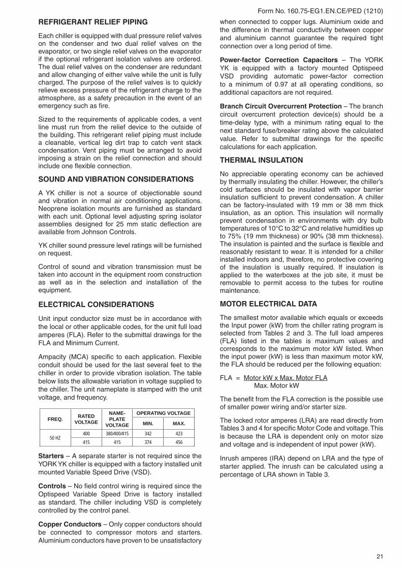
Unit input conductor size must be in accordance with the local or other applicable codes, for the unit full load amperes (FLA). Refer to the submittal drawings for the FLA and Minimum Current.
Ampacity (MCA) specifi c to each application. Flexible conduit should be used for the last several feet to the chiller in order to provide vibration isolation. The table below lists the allowable variation in voltage supplied to the chiller. The unit nameplate is stamped with the unit voltage, and frequency.
Starters – A separate starter is not required since the YORK YK chiller is equipped with a factory installed unit mounted Variable Speed Drive (VSD).
Controls – No fi eld control wiring is required since the Optispeed Variable Speed Drive is factory installed as standard. The chiller including VSD is completely controlled by the control panel.
Copper Conductors – Only copper conductors should be connected to compressor motors and starters. Aluminium conductors have proven to be unsatisfactory
when connected to copper lugs. Aluminium oxide and the difference in thermal conductivity between copper and aluminium cannot guarantee the required tight connection over a long period of time.
Power-factor Correction Capacitors – The YORK YK is equipped with a factory mounted Optispeed VSD providing automatic power-factor correction to a minimum of 0.97 at all operating conditions, so additional capacitors are not required.
Branch Circuit Overcurrent Protection – The branch circuit overcurrent protection device(s) should be a time-delay type, with a minimum rating equal to the next standard fuse/breaker rating above the calculated value. Refer to submittal drawings for the specifi c calculations for each application.
THERMAL INSULATION
No appreciable operating economy can be achieved by thermally insulating the chiller. However, the chiller’s cold surfaces should be insulated with vapor barrier insulation suffi cient to prevent condensation. A chiller can be factory-insulated with 19 mm or 38 mm thick insulation, as an option. This insulation will normally prevent condensation in environments with dry bulb temperatures of 10°C to 32°C and relative humidities up to 75% (19 mm thickness) or 90% (38 mm thickness). The insulation is painted and the surface is fl exible and reasonably resistant to wear. It is intended for a chiller installed indoors and, therefore, no protective covering of the insulation is usually required. If insulation is applied to the waterboxes at the job site, it must be removable to permit access to the tubes for routine maintenance.
MOTOR ELECTRICAL DATA
The smallest motor available which equals or exceeds the Input power (kW) from the chiller rating program is selected from Tables 2 and 3. The full load amperes (FLA) listed in the tables is maximum values and corresponds to the maximum motor kW listed. When the input power (kW) is less than maximum motor kW, the FLA should be reduced per the following equation:
FLA = Motor kW x Max. Motor FLA Max. Motor kW
The benefi t from the FLA correction is the possible use of smaller power wiring and/or starter size.
The locked rotor amperes (LRA) are read directly from Tables 3 and 4 for specifi c Motor Code and voltage. This is because the LRA is dependent only on motor size and voltage and is independent of input power (kW).
Inrush amperes (IRA) depend on LRA and the type of starter applied. The inrush can be calculated using a percentage of LRA shown in Table 3.
FREQ. RATEDVOLTAGE
NAME-PLATE
VOLTAGE
OPERATING VOLTAGE
MIN. MAX.
50 HZ400 380/400/415 342 423415 415 374 456

22
Form No. 160.75-EG1.EN.CE/PED (1210)
TABLE 2 – VARIABLE SPEED DRIVE SIZES
TABLE 3 – 50 Hz ELECTRICAL DATA
TABLE 4 – MOTOR STARTERS
NOTE: Inrush less than 100% of full load amps (FLA).
400
415
400
415

23
Form No. 160.75-EG1.EN.CE/PED (1210)
TABLE 5 – AVAILABLE COMPRESSOR/SHELL/MOTOR COMBINATIONS
YK MOD G COMBINATIONSCOMPRESSOR
CODESEVAPORATOR
CODESCONDENSER
CODESMOTOR CODES
50 HZQ3 AP TO AS AP TO AS
5CC-5COQ3, Q4CP TO CS CP TO CSDP TO DS DP TO DS
Q4 EP TO ET EP TO ET
Q5CP TO CS CP TO CS
5CE-5CODP TO DS DP TO DS
Q5, Q6, Q7EP TO ET EP TO ETFQ TO FT FQ TO FT
P7EP TO ET EP TO ET
5CP-5CUFQ TO FT FQ TO FT
P8 GQ TO GS EV TO EX
5CE-5CUP8, P9
HQ TO HS FV TO FXJP TO JS JP TO JSLQ TO LS LQ TO LS
H9KP TO KS, K2 TO K4 KP TO KS, K2 TO K4
5CK-5CWMQ TO MS, M2 TO M4 MP TO MS, M2 TO M4
K1 KT TO KX, K5 TO K7 KP TO KS, K2 TO K4
5CN-5DCK1, K2
MQ TO MS, M2 TO M4 MP TO MS, M2 TO M4NQ TO NS, N2 TO N4 NP TO NS, N2 TO N4PQ TO PS, P2 TO P4 PQ TO PS, P2 TO P4QQ TO QS, Q2 TO Q4 QQ TO QS, Q2 TO Q4
K3NQ TO NS, N2 TO N4 NP TO NS, N2 TO N4
5DA-5DHQQ TO QV, Q2 TO Q4 QQ TO QS, Q2 TO Q4RQ, RS, RV, R3, R5, R7 RQ TO RS, R2 TO R4
K4
RP, RR, RT, R2, R4, R6 RQ TO RS, R2 TO R4
5DA-5DJSQ, SS, SV, S3, S5, S7
SQ TO SS, S2 TO S4VP TO VS, V2 TO V5
XQ TO XS, X2 TO X4TP TO TS, T2 TO T5XQ TO XS, X2 TO X4
K7WP-WT, W1, W2, W4, W6 WQ TO WS, W1 TO W4
5DD-5DLZQ TO ZS, Z1 TO Z4 ZQ TO ZS, Z1 TO Z4
YK MOD G HEAT RECOVERY COMBINATIONSCOMPRESSOR
CODESEVAPORATOR
CODESCONDENSER
CODESMOTOR CODES
50 HZQ4 CP TO CS BW, BX
5CC-5COQ7 EP TO ET IW, IXH9 KP TO KS, K2 TO K4 OW, OX, O8, O9 5CK-5CWK2 MQ TO MS, M2 TO M4 UW, UX, U8, U9 5CN-5DCK7 ZQ TO ZS, Z1 TO Z4 YW, YX, Y8, Y9 5DD-5DL
YK MOD G HYBRID FALLING FILM COMBINATIONS
COMPRESSORCODES
HYBRIDFALLING FILM EVAPORATOR
CODES
CONDENSERCODES
MOTOR CODES
50 HZ
Q3AC, AD, A3, A4 AP TO AS
5CC-5COCC TO CE, C3 TO C5 CP TO CS
Q4CC TO CE, C3 TO C5 CP TO CSDC TO DE, D3 TO D5 DP TO DS
Q5CC TO CE, C3 TO C5 CP TO CS
5CE-5CODC TO DE, D3 TO D5 DP TO DS
Q5, Q6, Q7EC TO EE, D3 TO E5 EP TO ETFC TO FE, F3 TO F5 FQ TO FT
P7EC TO EE, D3 TO E5 EP TO ET
5CP-5CUFC TO FE, F3 TO F5 FQ TO FT
P8, P9GC TO GE, G3 TO G5 EV TO EX, E3 TO E4
5CE-5CUHC TO HE, H3 TO H5 FV TO FX, F3 TO F4
H9 KC, KD, K8, K9, K0 KP TO KS, K2 TO K4 5CK-5CW

24
Form No. 160.75-EG1.EN.CE/PED (1210)
DIMENSIONS (MM) - UNITP & Q COMPRESSOR UNITS

25
Form No. 160.75-EG1.EN.CE/PED (1210)
DIMENSIONS (MM) - UNIT
NOTES:1. All dimensions are approximate. Certifi ed dimensions are avail able on request. 2. For all waterboxes (compact shown above), determine overall unit length by adding waterbox depth to tube sheet length. 3. Water nozzles can be located on either end of unit. Add 13 mm to nozzle length for fl anged connections. 4. To determine overall height, add dimension "M" for the appropriate isolator type. 5. Use of motors with motor hoods may increase overall unit di men sions.
H COMPRESSOR UNITS
ADDITIONAL OPERATING HEIGHT CLEARANCE TYPE OF CHILLER MOUNTING MNEOPRENE PAD ISOLATORS 44SPRING ISOLATORS 25MM DEFLECTION 25DIRECT MOUNT 19

26
Form No. 160.75-EG1.EN.CE/PED (1210)
DIMENSIONS (MM) – UNIT
K COMPRESSOR UNITS
LD07139
NOTES:1. All dimensions are approximate. Certifi ed dimensions are avail able on request. 2. For all waterboxes (compact shown above), determine overall unit length by adding waterbox depth to tube sheet length. 3. Water nozzles can be located on either end of unit. Add 13 mm to nozzle length for fl anged connections. 4. To determine overall height, add dimension "M" for the appropriate isolator type. 5. Use of motors with motor hoods may increase overall unit di men sions.6. Tubesheets are provided with jacking point notches on P and larger shells.
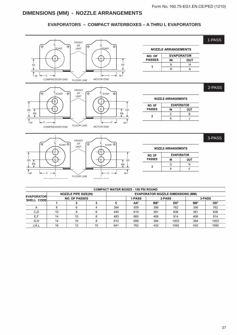
27
Form No. 160.75-EG1.EN.CE/PED (1210)
DIMENSIONS (MM) - NOZZLE ARRANGEMENTS
C CCOMPRESSOR END FLOOR LINE MOTOR END
AA
M
AA
M
A H
EVAP. EVAP.
FRONTOF
UNIT
M MC CFLOOR LINECOMPRESSOR END MOTOR END
COMPRESSOR END MOTOR END
B
C
J
K
EVAP. EVAP.FRONT
OFUNIT
BB BBDD DD
MM C CFLOOR LINE
F
G
N
P
EVAP. EVAP.
FRONTOF
UNIT
BBDD
BBDD
1-PASS
2-PASS
3-PASS
EVAPORATORS – COMPACT WATERBOXES – A THRU L EVAPORATORS
EVAPORATOR

28
Form No. 160.75-EG1.EN.CE/PED (1210)
See Notes on page 53.
EVAPORATORS – COMPACT WATERBOXES – M THRU Z EVAPORATORS
DIMENSIONS (MM) - NOZZLE ARRANGEMENTS - CONT.

29
Form No. 160.75-EG1.EN.CE/PED (1210)
F F
F F
FG

30
Form No. 160.75-EG1.EN.CE/PED (1210)
CONDENSERS – COMPACT WATERBOXES
FLOOR LINE
FLOOR LINE
FLOOR LINE
COMPRESSOR END MOTOR END
COMPRESSOR END MOTOR END
COMPRESSOR END MOTOR END
M M
COND. COND.
COND. COND.
COND. COND.
FRONTOF UNIT
FRONTOF UNIT
FRONTOF UNIT
1-PASS
2-PASS
3-PASS
P Q
S U
R T
W Y
V X
M M
M M
D D
D D
D D
BBBB
BBBB
DD DD
DD DD
CCCC
NOTES: 1. Standard water nozzles are furnished as welding stub-outs with ANSI/AWWA C-606 grooves, allowing the option of welding, fl anges, or use of ANSI/AWWA C-606
couplings. Factory-installed, class 150 (ANSI B16.5, round slip-on, forged carbon steel with 1.6 mm raised face), water fl anges nozzles are optional (add 13 mm to nozzle length). Companion fl anges, nuts, bolts, and gaskets are not furnished.
2. One, two and three pass nozzle arrangements are available only in pairs shown and for all shell codes. Any pair of evaporator nozzles may be used in combination with any pair of condenser nozzles.
3. Evaporator and condenser water must enter the waterbox through the bottom connection to achieve rated performance. 4. Connected piping should allow for removal of compact waterboxes for tube access and cleaning. 5. Add dimension "M" as shown on the unit dimensions page for the appropriate isolator type. 6. Standard 150 psi (1034 kPa) design pressure waterboxes shown.
7. Shell codes R,S,T,V,W,X, & Z use double letter nozzle codes in the same orientation as the single letter e.g. P = PP.
DIMENSIONS (MM) - NOZZLE ARRANGEMENTS - CONT.

31
Form No. 160.75-EG1.EN.CE/PED (1210)
F F
FG
F F
ONE PASS
THREE PASS
TWO PASS
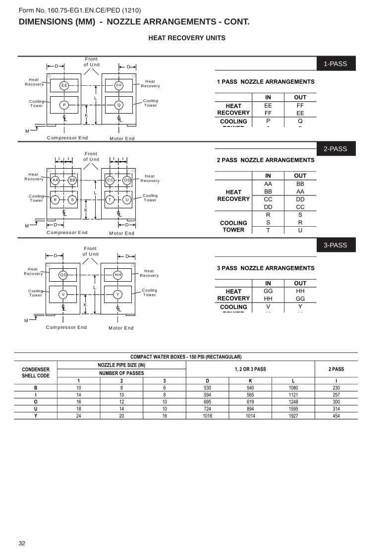
32
Form No. 160.75-EG1.EN.CE/PED (1210)
HEAT RECOVERY UNITS
M
K
D
CL
C om pressor E nd
Frontof U nit D
CL
M otor E nd
L
HeatHeat
Recovery
Tower
CoolingTower
HeatRecovery
HeatRecovery
CoolingTower
CoolingTowerP
EE FF
Q
M
K
D
CL
C om pressor E nd
Frontof U nit D
CL
M otor E nd
L
HeatHeat
Recovery
CoolingTower
HeatRecovery
HeatRecovery
CoolingTower
CoolingTowerV
GG HH
Y
M
K
D
CL
C om pressor E nd
Frontof U nit
D
CL
M otor E nd
L
HeatHeat
Recovery
Tower
CoolingTower
HeatRecovery
HeatRecovery
CoolingTower
CoolingTowerR
AA BB
S
CC
T U
DD
I
I
I
I
1-PASS
2-PASS
3-PASS
DIMENSIONS (MM) - NOZZLE ARRANGEMENTS - CONT.

33
Form No. 160.75-EG1.EN.CE/PED (1210)
EVAPORATORS – MARINE WATERBOXES
6
P
1OUT
C C
P
6 OUTIN
M MOTOR ENDCOMPRESSOR END MOTOR ENDCOMPRESSOR ENDFLOOR LINE
C C
IN
M FLOOR LINE
FRONT OF UNIT
P
Q
3
Q
8
R
MOTOR ENDCOMPRESSOR END MOTOR ENDCOMPRESSOR END FLOOR LINEFLOOR LINE
C
M
OUT
P 2IN
OUT
C R
M
FRONT OF UNIT FRONT OF UNIT
FRONT OF UNIT
Q
C
Q
MOTOR ENDCOMPRESSOR END MOTOR ENDCOMPRESSOR END FLOOR LINEFLOOR LINE
9
C
4
P
OUT
IN
M
R C R
IN5
10
M
OUT
P
FRONT OF UNIT FRONT OF UNIT
1-PASS
2-PASS
3-PASS
1
IN7
See Notes on pf 30.
DIMENSIONS (MM) - NOZZLE ARRANGEMENTS - CONT.

34
Form No. 160.75-EG1.EN.CE/PED (1210)
NOTES: 1. All dimensions are approximate. Certifi ed dimensions are available upon re quest. 2. Standard water nozzles are Schedule 40 pipe size, furnished as welding stub-outs with ANSI/AWWA C-606 grooves, allowing the option of
welding, fl anges, or use of ANSI/AWWA C-606 couplings. Factory-installed, class 150 (ANSI B16.5, round slip-on, forged carbon steel with 1.6 mm raised face), water fl anged nozzles are optional (add 13 mm to nozzle length). Companion fl anges, nuts, bolts, and gaskets are not furnished.
3. One-, two-, and three-pass nozzle arrangements are available only in pairs shown and for all shell codes. Any pair of evaporator nozzles may be used in com bi na tion with any pair of condenser nozzles. Compact waterboxes on one heat exchanger may be used with Marine Waterboxes on the other heat exchanger.
4. Water must enter the waterbox through the bottom connection to achieve rated performance. 5. Add dimension "M" as shown on the unit dimensions page for the appropriate isolator type.
F
DIMENSIONS (MM) - NOZZLE ARRANGEMENTS - CONT.

35
Form No. 160.75-EG1.EN.CE/PED (1210)
CONDENSERS – MARINE WATERBOXES
CLCL CL
DD
11 16
S
MFLOORLINECOMPRESSOR END MOTOR END COMPRESSOR END MOTOR END
COMPRESSOR END MOTOR END
COMPRESSOR END MOTOR END
COMPRESSOR END MOTOR END
COMPRESSOR END MOTOR END
M MFLOORLINE M
S
11 16
DDFRONT OF UNIT FRONT OF UNIT
15
CL CL
U
CL CL
DD
S
20
T
M U FLOORLINE M M
FLOORLINE
S
D D
14
T
M
19
FRONT OF UNITFRONT OF UNIT
CL CL
D
18
S
M M
17
TT
UFLOORLINE M
FLOORLINE
T
M
S12
13
DFRONT OF UNITFRONT OF UNIT
U
1-PASS
2-PASS
3-PASS
OUTIN OUT IN
OUT
IN
OUT
IN
OUT
IN
OUT
IN
DIMENSIONS (MM) - NOZZLE ARRANGEMENTS - CONT.

36
Form No. 160.75-EG1.EN.CE/PED (1210)
LD07179
NOTES: 1. All dimensions are approximate. Certifi ed dimensions are available upon re quest. 2. Standard water nozzles are Schedule 40 pipe size, furnished as welding stub-outs with ANSI/AWWA C-606 grooves, allowing the option
of weld ing, fl anges, or use of ANSI/AWWA C-606 couplings. Factory-installed, class 150 (ANSI B16.5, round slip-on, forged carbon steel with 1.6 mm raised face), water fl anged nozzles are optional (add 13 mm to nozzle length). Companion fl anges, nuts, bolts, and gaskets are not furnished.
3. One-, two-, and three-pass nozzle arrangements are available only in pairs shown and for all shell codes. Any pair of evaporator nozzles may be used in com bi na tion with any pair of condenser nozzles. Compact waterboxes on one heat exchanger may be used with Marine Waterboxes on the other heat exchanger.
4. Condenser water must enter the waterbox through the bottom connection for prop er operation of the sub-cooler to achieve rated per for mance. 5. Add dimension "M" as shown on the unit dimension page for the appropriate isolator type.
DIMENSIONS (MM) - NOZZLE ARRANGEMENTS - CONT.

37
Form No. 160.75-EG1.EN.CE/PED (1210)
11 16
M M
SS
D D
U U
CL LC
Frontof U nit
13
M M
S
D
U
CL
C ompressor End Motor End
Frontof U nit
12
TT
18
M
S
D
U
CL
Motor EndC ompressor End
Frontof U nit
17
TT
D
CL
D
CL
M
V V
M M
S
U
CL
C om pressor End M otor End
Frontof U nit
15
TT
M
S
D
U
CL
M otor EndC om pressor End
Frontof U nit
19
TT
D
CL
D
CL
M
20 14
S
V VD
1-PASS
2-PASS
3-PASS
CONDENSERS – MARINE WATERBOXESHeat Recovery Units - Main (Tower) Circuit Only
DIMENSIONS (MM) - NOZZLE ARRANGEMENTS - CONT.

38
Form No. 160.75-EG1.EN.CE/PED (1210)
WEIGHTS TABLE 6 – APPROXIMATE UNIT WEIGHT IN CLUD ING MOTOR2
2 Refer to product drawings for detailed weight information.
SHELLS COMPRESSOR SHIPPING WEIGHT (KGS.)
OPERATING WEIGHT (KGS.)
EST. REFRIGERANT CHARGE (KGS.) 1
A-A Q3 5,942 6,804 376C-B Q4 8,175 10,126 692C-C Q3, Q4 6,768 8,138 554C-C Q5 6,954 8,324 554D-D Q3, Q4 7,809 9,571 738D-D Q5 7,995 9,757 738E-E Q3, Q4 8,142 10,052 776E-E Q5,Q6,Q7,P7 8,328 10,238 776E-I Q7 10,690 13,328 819F-F Q5,Q6,Q7,P7 8,491 10,832 987G-E P8 9,208 10,977 903H-F P8,P9 10,478 12,701 1,184J-J P8,P9 10,886 13,200 1,157L-L P8,P9 12,429 15,377 1,436K-K H9 12,941 16,329 1,327K-K K1 14,107 16,420 1,473K-O H9 15,641 20,310 1,479M-M H9 15,513 19,777 1,662M-M K1,K2 17,373 21,364 1,662M-U K2 20,493 26,316 1,606N-N K1,K2 18,549 23,043 1,916N-N K3 21,773 24,540 1,916P-P K1,K2 18,824 23,542 1,749Q-Q K1,K2 20,548 25,764 1,930Q-Q K3 20,865 27,307 1,930R-R K3 23,950 31,888 2,087R-R K4 24,041 32,024 2,087S-S K4 26,762 34,609 2,184S-V K4 27,261 36,877 2,480X-T K4 26,853 36,288 2,421X-X K4 29,937 39,463 2,665W-W K7 36,061 47,174 3,630Z-Y K7 43,196 55,799 3,255Z-Z K7 36,515 47,628 3,168
1 Refrigerant charge quantity and weights will vary based on tube count.
TABLE 6A - APPROXIMATE UNIT WEIGHT INCLUDING MOTOR UNIT WITH HYBRID FALLING FILM EVAPORATOR
SHELLS COMPRESSOR SHIPPING WEIGHT (KGS.)
OPERATING WEIGHT (KGS.)
EST. REFRIGERANT CHARGE (KGS.) 1
A-A Q3 5,829 6,540 315C-C Q3, Q4 6,609 7,642 397C-C Q5 6,804 7,837 397D-D Q4 7,711 9,095 535D-D Q5 7,897 9,281 535E-E Q5,Q6,Q7,P7 8,482 9,843 508F-F Q5,Q6,Q7,P7 8,718 10,497 642G-E P8, P9 9,362 10,903 599H-F P8, P9 10,678 12,738 805K-K H9 13,086 15,458 826
1 Refrigerant charge quantity and weights will vary based on tube count and confi guration. Use for reference only.

39
Form No. 160.75-EG1.EN.CE/PED (1210)
TABLE 7 – EVAPORATOR MARINE WATERBOX WEIGHTS (KGS.)(TO BE ADDED TO STANDARD UNIT WEIGHTS SHOWN ON TABLE 6)
EVAP. CODESHIPPING WEIGHT OPERATING WEIGHTINCREASE - KGS. INCREASE - KGS.
1-PASS 2-PASS 3-PASS 1-PASS 2-PASS 3-PASSA 419 337 444 666 584 690
C,D 613 505 671 1,009 901 1,067E,F 852 572 943 1,532 1,252 1,624G,H 550 588 587 1,204 1,242 1,241J,K,L 794 836 842 1,753 1,794 1,800M,N 1,946 924 1,878 3,418 1,481 2,858P,Q 2,115 1,021 2,107 3,514 1,581 3,353
R,S,W 2,179 1,225 2,228 3,866 2,048 3,714X,Z 3,215 1,660 3,286 5,240 2,498 5,100
TABLE 8 – CONDENSER MARINE WATERBOX WEIGHTS (KGS.) (TO BE ADDED TO STANDARD UNIT WEIGHTS SHOWN ON TABLE 6)
COND. CODESHIPPING WEIGHT OPERATING WEIGHTINCREASE - KGS. INCREASE - KGS.
1-PASS 2-PASS 3-PASS 1-PASS 2-PASS 3-PASSA 346 257 367 578 489 600B 712 396 761 958 496 939
C,D 429 353 474 767 691 813E,F 329 368 359 606 781 772
I 937 485 922 1,369 642 1,242J,K,L 467 529 522 1,047 1,110 1,103M,N 1,119 603 1,054 2,206 1,110 2,078O 1,354 655 1,355 2,012 985 1,805
P,Q 1,678 843 1,702 2,976 1,421 2,717R,S 1,726 883 1,796 3,020 1,449 2,881
V,T,W 2,357 1,163 2,361 4,155 1,820 3,728U 1,652 859 1,637 2,427 1,159 2,164
X,Z 2,649 1,339 2,440 4,491 2,109 3,674Y 4,125 2,160 4,109 6,045 2,959 5,465

Form No. 160.75-EG1.EN.CE/PED (1210) Subject to change without notice. Revision 0 ALL RIGHTS RESERVED
www.johnsoncontrols.com