yokogawa - farnell element14 · both of these products evolved from yokogawa’s original 2280...
TRANSCRIPT

YOKOGAWA
POWERTRANSDUCER
CATALOG

Thank you for your interest in Yokogawa’s Power Transducer Product Line. This catalog includesthe Juxta AC Power Series transducers which are manufactured just-in-time at our Newnan, Georgiafacility. This enables YCA to offer very quick delivery and prompt customer service. Also included arethe Miniature Plastic Case transducers available in foot mount style as well as DIN rail mount. Withthis wide array, YCA can surely meet most any power transducer application you may have.
Since our establishment in the United States in 1957, Yokogawa Corporation of America (YCA) hasbecome a leading North American manufacturer and supplier of Test and Measurement, FieldInstrumentation (Flow, Pressure and Analytical Products), Process Control Equipment,Information Products
Headquartered just south of Atlanta, Georgia, YCA has sales offices across the United States. Ourcommitment to our customers is our number one priority, and we back it up with a network ofrepresentatives and distributors that reflect this commitment. Our 132 manufacturing and service locations give us a presence on every major continent, which means we have the globalresources to support all your application needs.
Our parent company, Yokogawa Electric Corporation, is dedicated to developing the mostadvanced control and instrumentation products and systems in the world. As a major globalplayer, the company anticipates the needs of the times, continually tackling new challenges andexploring new markets in order to provide the best solutions in the world.
Yokogawa’s commitment to innovation is reflected in our extraordinary investments in R&D, whichensure development of the most advanced products and services. As a result, we have securedmore than 4,500 patents and registrations, representing a number of important innovations,including the world’s first distributed control system and the first digital sensors for flow andpressure measurement.
Y O K O G A W A T R A N S D U C E R S

Yokogawa’s JUXTA “AC POWER SERIES” transducers (2469 & 2489) are rugged metalcase designs for utility and industrial applications. Most models are UL recognized under File E60579 and exceed IEEE472/ANSI C37.90.1 Surge Withstand Capability test. The“SWC” test assures maximum protection from damaging line transients caused byswitchgear operation or lightning strikes upstream on the system.
Typically, power transducers provide a reliable and accurate analog DC output propor-tional to the AC input from the secondary of potential and / or current transformers inswitchgear or control enclosures. The output is usually linked to remote monitoringequipment such as meters, recorders, PLC’s, SCADA systems, Energy ManagementSystems, etc. Usually, 0.5% accuracy is adequate for most industrial monitoring needs.Our 2469 meets this requirement. Most power utility applications, however, require ahigher level of accuracy. Our 2489 series, with 0.2% accuracy, is recommended for suchapplications.
The plastic case power transducers (2370 & 2460 series) offer versatility and compact-ness when panel space is tight. The 2460 series can be mounted on a DIN rail, along withrelays and terminal blocks, to maximize space and provide the ultimate in flexibility tothe panel designer. The 2370 series has the same height and width as the DIN rail mount,but has two mounting feet which only require two drill holes and half the space of mostmetal case transducers. Both of these models offer 0.5% accuracy and come in one uni-form case size from AC Amps to 3P4W Watts or Vars.
Both of these products evolved from Yokogawa’s original 2280 series Power LineTransducer design which is broadly accepted throughout the world. For information onthe 2281 through 2289 models, please request bulletin 2280-E from Yokogawa on ourreply card inserted in the catalog.
Yokogawa offers a complete line of transducers for expansion, retrofit or upgrade ofyour power system. We hope the specification data and associated information in thiscatalog will provide all that is needed to make our transducers your choice for reliablepower monitoring in your plant or equipment design.
JUXTA METAL CASE TRANSDUCERS - 0.2% AND 0.5% ACCURACYAC CURRENT TRANSDUCERS (true RMS and Average sensing) . . . . . . . . . . . . . . . .PAGE 2AC VOLTAGE TRANSDUCERS (true RMS and Average sensing) . . . . . . . . . . . . . . . .PAGE 4DC TO DC ISOLATORS . . . . . . . . . . . . . . . . . . . . . . . . . . . . . . . . . . . . . . . . . . . . . . . .PAGE 6AC WATT TRANSDUCERS . . . . . . . . . . . . . . . . . . . . . . . . . . . . . . . . . . . . . . . . . . . . .PAGE 8AC VAR TRANSDUCERS . . . . . . . . . . . . . . . . . . . . . . . . . . . . . . . . . . . . . . . . . . . . . .PAGE 10COMBINATION WATT / VAR TRANSDUCERS . . . . . . . . . . . . . . . . . . . . . . . . . . . . . .PAGE 12POWER FACTOR TRANSDUCERS . . . . . . . . . . . . . . . . . . . . . . . . . . . . . . . . . . . . . . .PAGE 14PHASE ANGLE TRANSDUCERS . . . . . . . . . . . . . . . . . . . . . . . . . . . . . . . . . . . . . . . .PAGE 16FREQUENCY TRANSDUCERS . . . . . . . . . . . . . . . . . . . . . . . . . . . . . . . . . . . . . . . . . .PAGE 18JUXTA 2489 SERIES ACCURACY . . . . . . . . . . . . . . . . . . . . . . . . . . . . . . . . . . . . . . .PAGE 20SELECTING A WATT OR VAR TRANSDUCER . . . . . . . . . . . . . . . . . . . . . . . . . . . . . .PAGE 21TRANSDUCER TERMINOLOGY . . . . . . . . . . . . . . . . . . . . . . . . . . . . . . . . . . . . . . . .PAGE 22
PLASTIC CASE MINIATURE TRANSDUCERS - 0.5% ACCURACY2371-2378 FOOT MOUNT / 2461-2468 DIN RAIL MOUNT . . . . . . . . . . . . . . . . . . .PAGE 24
TABLE OF CONTENTS
Y O K O G A W A P O W E R T R A N S D U C E R S
PRODUCT OVERVIEW
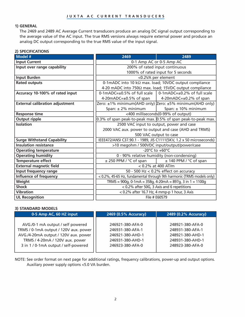
2469 24890-1 Amp AC or 0-5 Amp AC
200% of rated input continuous1000% of rated input for 5 seconds
<0.2VA per element0-1mADC into 10 kΩ max. load; 10VDC output compliance4-20 mADC into 750Ω max. load; 15VDC output compliance
0-1mADC=±0.5% of full scale 0-1mADC=±0.2% of full scale4-20mADC=±0.5% of span 4-20mADC=±0.2% of span
Zero: ±1% minimum(AHD only) Zero: ±5% minimum(AHD only)Span: ± 2% minimum Span: ± 10% minimum
<400 milliseconds(0-99% of output)0.3% of span peak-to-peak max. 0.5% of span peak-to-peak max.
2500 VAC input to output, power and case2000 VAC aux. power to output and case (AHD and TRMS)
500 VAC output to caseIEEE472/ANSI C37.90.1 - 1989, JIS C1111(5KV, 1.2 x 50 microseconds)
>10 megohm / 500VDC input/output/power/case-20°C to +60°C
0 - 90% relative humidity (non-condensing)± 250 PPM / °C of span ± 140 PPM / °C of span
< 0.2% at 400 AT/m50 - 500 Hz < 0.2% effect on accuracy
< 0.2%, 45-65 Hz, fundamental through 9th harmonic (TRMS models only)TRMS = 900g, 0-1mA = 358g, 4-20mA = 897g, 3 in 1 = 1100g
< 0.2% after 50G, 3 Axis and 6 repetitions< 0.2% after 16.7 Hz, 4 mmp-p 1 hour, 3 Axis
File # E60579
2469 (0.5% Accuracy) 2489 (0.2% Accuracy)
246921-380-AFA-0 248921-380-AFA-0246931-380-AFA-1 248931-380-AFA-1246921-380-AHD-1 248921-380-AHD-1246931-380-AHD-1 248931-380-AHD-1246923-380-AFA-0 248923-380-AFA-0
0-5 Amp AC, 60 HZ input
AVG./0-1 mA output / self poweredTRMS / 0-1mA output / 120V aux. powerAVG./4-20mA output / 120V aux. power
TRMS / 4-20mA / 120V aux. power3 in 1 / 0-1mA output / self-powered
2
1) GENERALThe 2469 and 2489 AC Average Current transducers produce an analog DC signal output corresponding tothe average value of the AC input. The true RMS versions always require external power and produce ananalog DC output corresponding to the true RMS value of the input signal.
2) SPECIFICATIONSModel #Input CurrentInput over range capability
Input BurdenRated outputs
Accuracy 10-100% of rated input
External calibration adjustment
Response timeOutput rippleIsolation
Surge Withstand CapabilityInsulation resistanceOperating temperatureOperating humidityTemperature effectExternal magnetic fieldInput frequency rangeInfluence of frequencyWeightShockVibrationUL Recognition
3) STANDARD MODELS
NOTE: See order format on next page for additional ratings, frequency calibrations, power-up and output options.Auxiliary power supply options <5.0 VA burden.
J U X T A A C C U R R E N T T R A N S D U C E R S

1 85-135 VAC2 170-264 VAC
21 Average current23 3 in 1 Avg. current31 True RMS current
3
4) ORDER FORMAT 2469 / 89 - - -(3) Input
Model# (1) Transducer function (2) Input frequency (4) Output (5) Aux. power24692489
37 0-1 Amp AC38 0-5 Amp AC
0 Inputpowered
0 60 Hz1 50 Hz2 50/60 Hz4 400 Hz5 Other
AFA 0-1 mADC(21 & 23 only)
AFA 0-1 mADC(TRMS only)
AHD 4-20 mADC(21 & 31 only)
5) CONNECTION DIAGRAMS FOR CT INPUT
6) MOUNTING AND OUTLINE DIMENSIONS:
SELF POWERED 3 IN 1 CURRENTAUXILIARY POWERED
SELF POWERED 3 IN 1 CURRENTAUXILIARY POWERED
-
LOAD
L1 L2LINE
1 4
DCOUTPUT
+
2 3
246921248921
246921248921
246921248921246931248931
LOAD
L1 L2LINE
1 2 3 4 5 6
DCOUTPUT
AUXPOWER
- +-+
246923248923
-LOAD
L1L2 L3LINE
1 2 3 4
1 2 3 4
1 2 3 4
DC OUTPUT
DC OUTPUT
DC OUTPUT
+
+
+
-
-
246923248923
246921248921246931248931
J U X T A A C C U R R E N T T R A N S D U C E R S(1) (2) (3) (4) (5)
(mm)inches
(77.15)3.037
(88.9)3.500
(10.1)3.976
(51
.11
)
2.0
12
(50
)
1.9
69
(38
.1)
1.5
00
(14
.7)
.57
9
(10
4.0
3)
4.0
96
(89
.33
)
3.5
17
++ ++ + +
++ ++ + +
++ ++ + +
(95.72)
3.769(78)
3.071(38.1)
1.5
(133
)
5.23
6
(120
.65)
4.75
0
(111
.6)
4.39
4
+
(119
.8)
4.71
7
(105
.1)
4.13
8
(14.
7)
.579
+ + + + + ++ +
(95
.72
)3
.76
9
(78
)3
.07
1
(38
.1)
1.5
(111.6)4.394
(120.65)4.750
(133)5.236
(11
9.8
)
4.7
17
(10
5.1
)
4.1
38
(14
.7)
.57
9

2469 24890-150 VAC or 0-300 VAC
120% of rated input continuous150 VAC: <1.8VA / element; 300 VAC: <3.6VA / element
150 VAC: <0.8VA; 300 VAC: <1.6VA0-1mADC into 10 kΩmax. load; 10VDC output compliance
4-20 mADC into 750Ω max. load; 15VDC output compliance0-1mADC=±0.5% of full scale 0-1mADC=±0.2% of full scale
4-20mADC=±0.5% of span 4-20mADC=±0.2% of spanZero: ±1% minimum(AHD only) Zero: ±5% minimum(AHD only)
Span: ±2% minimum Span: ±10% minimum<400 milliseconds(0-99% of output)
0.3% of span peak-to-peak max. 0.5% of span peak-to-peak max.2500 VAC input to output, power and case
2000 VAC aux. power to output and case(AHD + TRMS)500 VAC output to case
IEEE472/ANSI C37.90.1 - 1989, JIS C1111(5KV 1.2 x 50 microseconds)>10 megohm / 500VDC input/output/power/case
-20°C to +60°C0 - 90% relative humidity (non-condensing)
± 250 PPM / °C of span ± 140 PPM / °C of span< 0.2% at 400 AT/m
50 - 500 Hz < 0.2% effect on accuracy< 0.2%, 45-65 Hz, fundamental through 9th harmonic (TRMS models only)
TRMS = 900g, 0-1mA = 358g, 4-20mA = 897g, 3 in 1 = 1100g< 0.2% after 50G, 3 Axis and 6 repetitions
< 0.2% after 16.7 Hz, 4 mmp-p 1 hour, 3AxisFile # E60579
0-150 VAC, 60 HZ input
AVG./0-1 mA / self poweredTRMS / 0-1mA / 120V aux. powerAVG./4-20mA / 120V aux. power
TRMS / 4-20mA / 120V aux. power3 in 1 / 0-1mA output / self-powered
4
2469 (0.5% Accuracy) 2489 (0.2% Accuracy)
246922-330-AFA-0 248922-330-AFA-0246932-330-AFA-1 248932-330-AFA-1246922-330-AHD-1 248922-330-AHD-1246932-330-AHD-1 248932-330-AHD-1246924-330-AFA-0 248924-330-AFA-0
1) GENERALThe 2469 and 2489 AC Average Voltage transducers produce an analog DC signal output corresponding tothe average value of the AC input. The true RMS versions always require external power and produce ananalog DC output corresponding to the true RMS value of the input signal.
2) SPECIFICATIONSModel #Input VoltageInput over range capabilityInput Burden (Averaging models)Input Burden (true RMS models)Rated outputs
Accuracy 10-100% of rated input
External calibration adjustment
Response timeOutput rippleIsolation
Surge Withstand CapabilityInsulation resistanceOperating temperatureOperating humidityTemperature driftExternal magnetic fieldInput frequency rangeInfluence of frequencyWeightShockVibrationUL Recognition
3) STANDARD MODELS
NOTE: See order format on next page for additional ratings, frequency calibrations, power-up and output options.Auxiliary power supply options <5.0 VA burden.
J U X T A A C V O L T A G E T R A N S D U C E R S

(77.15)3.037
(88.9)3.500
(10.1)3.976
(51
.11
)
2.0
12
(50
)
1.9
69
(38
.1)
1.5
00
(14
.7)
.57
9
(10
4.0
3)
4.0
96
(89
.33
)
3.5
17
22 Average Voltage24 3 in 1 Avg. Voltage32 True RMS Voltage
5
4) ORDER FORMAT 2469 / 89 - - -(3) Input
Model# (1) Transducer function (2) Input frequency (4) Output (5) Aux. power*24692489
33 0-150 VAC36 0-300 VAC
0 Inputpowered
1 85-135 VAC2 170-264 VAC
0 60 Hz1 50 Hz2 50/60 Hz4 400 Hz5 Other
AFA 0-1 mADC(22 & 24 only)
AFA 0-1 mADC(TRMS only)
AHD 4-20 mADC(22 & 32 only)
*Contact FactoryFor Other Power
Supply Options5) CONNECTION DIAGRAMS FOR PT INPUT
6) MOUNTING AND OUTLINE DIMENSIONS:
SELF POWERED 3 IN 1 VOLTAGEAUXILIARY POWERED
SELF POWERED 3 IN 1 VOLTAGEAUXILIARY POWERED
246922248922
246924248924
++ ++ + +
++ ++ + +
++ ++ + +
(95.72)
3.769(78)
3.071(38.1)
1.5
(133
)
5.23
6
(120
.65)
4.75
0
(111
.6)
4.39
4
+
(119
.8)
4.71
7
(105
.1)
4.13
8
(14.
7)
.579
246922248922246932248932
246922248922
246924248924
246922248922246932248932
+ + + + + ++ +
(95
.72
)3
.76
9
(78
)3
.07
1
(38
.1)
1.5
(111.6)4.394
(120.65)4.750
(133)5.236
(11
9.8
)
4.7
17
(10
5.1
)
4.1
38
(14
.7)
.57
9
-
LOAD
L1 L2LINE
1
DCOUTPUT
+
2 3 4
-
LOAD
L1 L2LINE
1
DCOUTPUT
+
2 3 4 5 6
AUXPOWER
(OPTIONAL)
-+
LOAD
L1L2 L3LINE
1 2 3 4
1 2 3 4
1 2 3 4
DC OUTPUT
DC OUTPUT
DC OUTPUT
+
+
+
-
-
-
J U X T A A C V O L T A G E T R A N S D U C E R S(1) (2) (3) (4) (5)
(mm)inches

2469 (0.5% accuracy)
0-50mVDC and 0-1mADC are standard
Varies with input current or voltage
< 1 mADC
10 VDC
± 0.5% of full scale
± 5% minimum
± 5% minimum
< 500 milliseconds (0-99% of output)
2600 VAC input to output, power and case
1000 VAC aux. power to output and case
1000 VAC output to case
IEEE472/ANSI C37.90.1-1989 SWC TEST
0° C to +40° C
20 - 90% relative humidity (non-condensing)
908g (2 lbs.)
115V AC ±10%, 5.0 VA Burden
6
Input / Output Relationship0-50mVDC / 0-1mADC0-50mVDC / 4-20mADC0-50mVDC / 0-10VDC
0-1mADC / 0-1mADC0-1mADC / 4-20mADC0-1mADC / 0-10VDC
Model # Description246911-001-AFA-1 / DC Voltage input246911-001-AHD-1 / DC Voltage input246911-001-VMT-1 / DC Voltage input
246912-101-AFA-1 / DC Current input246912-101-AHD-1 / DC Current input246912-101-VMT-1 / DC Current input
1) GENERALThe 2469 series DC to DC isolator provides an isolated analog output proportional to the DC voltage orcurrent input. Standard inputs are 50mVDC and 1 mADC. Auxiliary power is required to power the DC toDC isolator. Other DC inputs and power options are available on special order from Yokogawa.
2) SPECIFICATIONSModel #
Input signal ranges
Input impedance
Input burden
Output compliance
Accuracy 10-100% rated input
Span adjustment
Zero adjustment
Response time
Isolation
Surge withstand capability
Operating temperature
Operating humidity
Weight
Auxiliary Power Supply
3) STANDARD MODELS
J U X T A D C T O D C I S O L A T O R S

7
4) ORDER FORMAT 2469 - - -
Model# (1) Transducer function (2) Input (3) Output (4) Aux. power2469 11 DC Voltage input
12 DC Current input1 115VAC
±10%AFA 0-1mADCAHD 4-20mADCVMT 0-10VDC
001 0-50 mVDC101 0-1 mADC
Consult factory for other input / output / power-up options
5) CONNECTION DIAGRAMS
6) MOUNTING AND OUTLINE DIMENSIONS:
-
1
DCOUTPUT
+
2 3 4 5 6
AUX POWER
-+
DC INPUT
+ + + + + ++ +
(95.
72)
3.76
9
(78)
3.07
1
(38.
1)1.
5
(111.6)4.394
(120.65)4.750
(133)5.236
(119
.8)
4.71
7
(105
.1)
4.13
8
(14.
7).5
79
J U X T A D C T O D C I S O L A T O R S(1) (2) (3) (4)
(mm)inches

120 VAC, 5AAC, 60 Hz, input poweredWatt 1P2W, 0-1mA output (1 Element)Watt 1P2W, 4-20mA output (1 Element)Watt 3P3W, 0-1mA output (2 Element)Watt 3P3W, 4-20mA output (2 Element)Watt 3P4W, 0-1mA output (21⁄2 Element)Watt 3P4W, 4-20mA output (21⁄2 Element)Watt 3P4W, 0-1mA output (3 Element)Watt 3P4W, 4-20mA output (3 Element)
2469 24890-1 Amp AC or 0-5 Amp AC
10 to 200% of rated input 0-200% of rated input200% of rated input continuous
1000% of rated input for 5 seconds< 0.2VA per element
120V 240V 120V 240V100-135VAC 200-264VAC 85-135VAC 170-264VAC
0-120% rated input 0-120% of rated input< 0.5VA < 1.0VA < 0.3VA < 0.6VA
150% of rated input without damage (Auxiliary powered only)0 to ±1mADC into 10kΩ max. load; 10VDC output compliance4-20 mADC into 750Ω max. load; 15VDC output compliance0 ± 1mADC = 0.5% of full scale 0±1mADC = ±0.1% rdg. ± 0.05%FS4-20mADC = 0.5% of span 4-20mADC = ±0.2% of span
120VAC: 1 Amp = 0-100 Watts; 5 Amp = 0-500 Watts240VAC: 1 Amp = 0-200 Watts; 5 Amp = 0-1000 WattsZero: ± 1% minimum Zero: ± 5% minimumSpan: ± 2% minimum Span: ± 10% minimum
< 400 milliseconds (0-99% of output)0.3% of span peak-to-peak max. 0.5% of span peak-to-peak max.
2500 VAC input to output, power and case2000 VAC aux. power to output and case
500 VAC output to caseIEEE472/ANSI C37.90.1 - 1989, JIS C1111 (5KV 1.2 x 50 microseconds)
> 10 megohm / 500VDC input/output/power/case-20°C to +60°C 1mA (-20°to+70°C), 4-20mA(-20°to+60°C)0 - 90% relative humidity (non-condensing)
±250 PPM / °C of span 1mA ±50FS, 4-20mA ±75span (PPM/°C)< 0.2% at 400 AT/m
<0.5% <0.2%
<0.25%, 45-65 Hz, fundamental through 9th harmonic1200g (2.65 lbs.)
<0.2% after 50G, 3 Axis and 6 repetitions<0.2% after 16.7 Hz, 4 mmp-p 1 hour, 3 Axis
File # E60579
Model #Current input / range
Current input over range capability
Current input burdenVoltage inputs and range:
Input powered rangeAuxiliary powered range
Voltage input burden per elementSustained Voltage input overangeRated outputs
Accuracy
Output calibration / element
External calibration adjustment
Response timeOutput rippleIsolation
Surge Withstand CapabilityInsulation resistanceOperating temperatureOperating humidityTemperature effectExternal magnetic fieldInfluence : unbalanced currents /phase interaction / Power FactorInfluence of frequencyWeightShockVibrationUL Recognition
NOTE: See order format on next page for additional ratings, frequency calibrations, power-up and output options.Auxiliary power supply options <5.0 VA burden.
8
2469 (0.5% Accuracy) 2489 (0.2% Accuracy)246951-540-AFA-0 248951-540-AFA-0246951-540-AHD-0 248951-540-AHD-0246953-540-AFA-0 248953-540-AFA-0246953-540-AHD-0 248953-540-AHD-0246954-540-AFA-0 248954-540-AFA-0246954-540-AHD-0 248954-540-AHD-0246955-540-AFA-0 248955-540-AFA-0246955-540-AHD-0 248955-540-AHD-0
1) GENERALThe 2469 and 2489 AC Watt transducers produce an analog output equal to the Watts measured by theinput. The typical calibration is 500 Watts / element for 120V and 5A AC transformer secondary inputs.
2) SPECIFICATIONS
3) STANDARD MODELS
J U X T A A C W A T T T R A N S D U C E R S

5) CONNECTION DIAGRAMS WITH PT AND CT INPUTS
1P2W (1 element) 3P3W Delta (11⁄2 element)
-
LOAD
L1L2 L3LINE
1 2 3 4 5 6
7 8 9 10 11 12
DCOUTPUT
+
AUX POWER(OPTIONAL)
- +
-
LOAD
L1L2 L3LINE
1 2 3 4 5 6
7 8 9 10 11 12
DCOUTPUT
+
AUX POWER(OPTIONAL)
- +
51 Watt 1P2W (1 Element)52 Watt 3P3W (11⁄2 Element)*53 Watt 3P3W (2 Element)54 Watt 3P4W (21⁄2 Element)55 Watt 3P4W (3 Element)
9
4) ORDER FORMAT 2469 / 89 - - -(3) Input
Model# (1) Transducer function (2) Input frequency (4) Output (5) Aux. power**24692489
53 120VAC/ 1AAC54 120VAC/ 5AAC57 240VAC/ 1AAC58 240VAC/ 5AAC
0 Inputpowered
1 120 VAC2 240 VAC
0 60 Hz1 50 Hz4 400 Hz5 Other
AFA 0-1 mADCAFB ±1 mADCAHD 4-20 mADCAHF 12±8 mADC
**Contact FactoryFor Other Power
Supply Options
*Not UL
6) MOUNTING AND OUTLINE DIMENSIONS:
3P3W Delta (2 element)
3P4W Wye (3 element)3P4W Wye (21⁄2 element)
-
LOAD
L1 L2LINE
1 2 3 4 5 6
7 8 9 1011 12
DCOUTPUT
+
AUX POWER(OPTIONAL)
- +
246951248951
246953248953
- +
AUX POWER(OPTIONAL)
LOAD
L1L2 L3 NLINE
1 2 3 4 5 6 7 8
9 10 11 12 13 14 15 16
DCOUTPUT
-
+
- +
AUX POWER(OPTIONAL)
LOAD
L1L2 L3 NLINE
1 2 3 4 5 6 7 8
9 10 11 12 13 14 15 16
DCOUTPUT
-
+
246954248954
(95.
72)
3.76
9
(78)
3.07
1
(38.
1)1.
5
(111.6)4.394
(120.65)4.750
(133)5.236
(119
.8)
4.71
7
(105
.1)
4.13
8
(14.
7).5
79
+ + + + + ++ +
+ + + + + ++ +
246951248951
246952248952
246953248953
(95.
72)
3.76
9
(78)
3.07
1
(38.
1)
(111.6)4.394
(120.65)4.750
(133)5.236
(119
.8)
4.71
7
(105
.1)
4.13
8
(14.
7).5
79
+ + + + + ++ ++ +
+ + + + + ++ ++ +
1.5
246954248954
246955248955
246955248955
246952248952
J U X T A A C W A T T T R A N S D U C E R S(1) (2) (3) (4) (5)
(mm)inches

120 VAC, 5AAC, 60 Hz, input poweredVAR 1P2W, ±1mA output (1 Element)VAR 1P2W, 12±8mA output (1 Element)VAR 3P3W, ±1mA output (2 Element)VAR 3P3W, 12±8mA output (2 Element)VAR 3P4W, ±1mA output (21⁄2 Element)VAR 3P4W, 12±8mA output (21⁄2 Element)VAR 3P4W, ±1mA output (3 Element)VAR 3P4W, 12±8mA output (3 Element)
2469 (0.5% Accuracy) 2489 (0.2% Accuracy)246961-540-AFB-0-M 248961-540-AFB-0-M246961-540-AHF-0-M 248961-540-AHF-0-M246963-540-AFB-0-M 248963-540-AFB-0-M246963-540-AHF-0-M 248963-540-AHF-0-M246964-540-AFB-0-M 248964-540-AFB-0-M246964-540-AHF-0-M 248964-540-AHF-0-M246965-540-AFB-0-M 248965-540-AFB-0-M246965-540-AHF-0-M 248965-540-AHF-0-M
2469 24890-1 Amp AC or 0-5 Amp AC
10 to 200% of rated input 0-200% of rated input200% of rated input continuous
1000% of rated input for 5 seconds< 0.2VA per element
120V 240V 120V 240V100-135VAC 200-264VAC 85-135VAC 170-264VAC
0-120% rated input 0-120% of rated input< 0.5VA < 1.0VA < 0.3VA < 0.6VA
150% of rated input without damage (Auxiliary powered only)0 to ±1mADC into a 10kΩ max. load; 10VDC output compliance12±8mADC into a 750Ω max. load; 15VDC output compliance0 ± 1mADC = ±0.5% of full scale 0±1mADC = ±0.1% rdg. ± 0.1%FS12±8mADC = ±0.5% of span 12±8mADC = ±0.2% of span
120VAC: 1 Amp = 0-100 VARS; 5 Amp = 0-500 VARS240VAC: 1 Amp = 0-200 VARS; 5 Amp = 0-1000 VARSZero: ± 1% minimum Zero: ± 5% minimumSpan: ± 2% minimum Span: ± 10% minimum
< 400 milliseconds (0-99% of output)0.3% of span peak-to-peak max. 0.5% of span peak-to-peak max.
2500 VAC input to output, power and case2000 VAC aux. power to output and case
500 VAC output to caseIEEE472/ANSI C37.90.1 - 1989, JIS C1111 (5KV 1.2 x 50 microseconds)
> 10 megohm / 500VDC input/output/power/case-20°C to +60°C
0 - 90% relative humidity (non-condensing)±250 PPM / °C of span 1mA ±50FS, 4-20mA ±80span (PPM/°C)
< 0.2% at 400 AT/m<0.5% <0.2%
1200g (2.65 lbs.)<0.2% after 50G, 3 Axis and 6 repetitions
<0.2% after 16.7 Hz, 4 mmp-p 1 hour, 3 AxisFile # E60579
NOTE: See order format on next page for additional ratings, frequency calibrations, power-up and output options.Auxiliary power supply options <5.0 VA burden.
10
1) GENERALThe 2469 and 2489 AC VAR transducers produce an analog output equal to the VARS measured by theinput. The typical calibration is 500 VARS / element for 120V and 5A AC transformer secondary inputs.
2) SPECIFICATIONSModel #Current input / range
Current input over range capability
Current input burdenVoltage inputs and range:
Input powered rangeAuxiliary powered range
Voltage input burden per elementSustained Voltage input overangeRated outputs
Accuracy
Output calibration / element
External calibration adjustment
Response timeOutput rippleIsolation
Surge Withstand CapabilityInsulation resistanceOperating temperatureOperating humidityTemperature effectExternal magnetic fieldInfluence : unbalanced currents /phase interaction / Power FactorWeightShockVibrationUL Recognition
3) STANDARD MODELS
J U X T A A C V A R T R A N S D U C E R S

61 VAR 1P2W (1 Element)62 VAR 3P3W (11⁄2 Element)*63 VAR 3P3W (2 Element)64 VAR 3P4W (21⁄2 Element)65 VAR 3P4W (3 Element)
11
4) ORDER FORMAT 2469 / 89 - - - -
Model# (1) Transducer function (2) Input (3) Frequency (4) Output (5) Aux. power** relationship24692489
53 120V/1AAC54 120V/5AAC57 240V/1AAC58 240V/5AAC
0 Inputpowered
1 120 VAC2 240 VAC
0 60 Hz1 50 Hz4 400 Hz5 Other
AFB ±1 mADCAHF 12 ±8mADC
**Contact FactoryFor Other Power
Supply Options
M LAG=+POL.P LEAD=+POL.
(6) Input/output
5) CONNECTION DIAGRAMS WITH PT AND CT INPUTS
6) MOUNTING AND OUTLINE DIMENSIONS:
1P2W (1 element) 3P3W Delta (11⁄2 element) 3P3W Delta (2 element)
3P4W Wye (3 element)3P4W Wye (21⁄2 element)
-
LOAD
L1 L2LINE
1 2 3 4 5 6
7 8 9 1011 12
DCOUTPUT
+
AUX POWER(OPTIONAL)
- +
246961248961
-
LOAD
L1L2 L3LINE
1 2 3 4 5 6
7 8 9 10 11 12
DCOUTPUT
+
AUX POWER(OPTIONAL)
- +
246962248962
- +
AUX POWER(OPTIONAL)
LOAD
L1L2 L3 NLINE
1 2 3 4 5 6 7 8
9 10 11 12 13 14 15 16
DCOUTPUT
-
+
246965248965
-
LOAD
L1L2 L3LINE
1 2 3 4 5 6
7 8 9 10 11 12
DCOUTPUT
+
AUX POWER(OPTIONAL)
- +
246963248963
(95.
72)
3.76
9
(78)
3.07
1
(38.
1)1.
5
(111.6)4.394
(120.65)4.750
(133)5.236
(119
.8)
4.71
7
(105
.1)
4.13
8
(14.
7).5
79
+ + + + + ++ +
+ + + + + ++ +
246961248961
246962248962
246963248963
(95.
72)
3.76
9
(78)
3.07
1
(38.
1)
(111.6)4.394
(120.65)4.750
(133)5.236
(119
.8)
4.71
7
(105
.1)
4.13
8
(14.
7).5
79
+ + + + + ++ ++ +
+ + + + + ++ ++ +
1.5
246964248964
246965248965
- +
AUX POWER(OPTIONAL)
LOAD
L1L2 L3 NLINE
1 2 3 4 5 6 7 8
9 10 11 12 13 14 15 16
DCOUTPUT
-
+
246964248964
J U X T A A C V A R T R A N S D U C E R S
(1) (2) (3) (4) (5) (6)
(mm)inches
*Not UL

2469 24890-1 Amp AC or 0-5 Amp AC
10 to 200% of rated input 0-200% of rated input200% of rated input continuous
1000% of rated input for 5 seconds< 0.2VA per element
120V 240V 120V 240V100-135VAC 200-264VAC 85-135VAC 170-264VAC
0-120% rated input 0-120% of rated input< 0.5VA < 1.0VA < 0.3VA < 0.6VA
150% of rated input without damage (Auxiliary powered only)0 to ±1mADC into a 10kΩ max. load; 10VDC output compliance
4-20 mADC into 750Ω max. load; 15VDC output compliance±0.5% of full scale ± 0.1% of reading. ± 0.05% full scale
±0.5% of full scale ± 0.1% of reading. ± 0.1% full scale±0.5% of span ± 0.2% of span
Zero: ± 1% minimum Zero: ± 5% minimumSpan: ± 2% minimum Span: ± 10% minimum
< 400 milliseconds (0-99% of output)0.3% of span peak-to-peak max. 0.5% of span peak-to-peak max.
2500 VAC input to output, power and case2000 VAC aux. power to output and case
500 VAC output to caseIEEE472/ANSI C37.90.1 - 1989, JIS C1111 (5KV 1.2 x 50 microseconds)
> 10 megohm / 500VDC input/output/power/case-20°C to +60°C
0 - 90% relative humidity (non-condensing)±250 PPM / °C of span 1mA = W ± 50FS, V ±75span (PPM/°C)
< 0.2% at 400 AT/m<0.5% <0.2%
<0.25%, 45-65 Hz, fundamental through 9th harmonic (Watt only)1200g (2.65 lbs.)
<0.2% after 50G, 3 Axis and 6 repetitions<0.2% after 16.7 Hz, 4 mmp-p 1 hour, 3 Axis
File # E60579
120 VAC, 5AAC, 60 Hz, input poweredW/V 1P2W, 0±1mA output (1 Element)W/V 1P2W, 4-20mA output (1 Element)*W/V 3P3W, 0±1mA output (2 Element)W/V 3P3W, 4-20mA output (2 Element)*W/V 3P4W, 0±1mA output (21⁄2 Element)W/V 3P4W, 4-20mA output (21⁄2 Element)*W/V 3P4W, 0±1mA output (3 Element)W/V 3P4W, 4-20mA output (3 Element)*
2469 (0.5% Accuracy) 2489 (0.2% Accuracy)246941-540-AFB-0-M 248941-540-AFB-0-M246941-540-AHD-0-M 248941-540-AHD-0-M246943-540-AFB-0-M 248943-540-AFB-0-M246943-540-AHD-0-M 248943-540-AHD-0-M246944-540-AFB-0-M 248944-540-AFB-0-M246944-540-AHD-0-M 248944-540-AHD-0-M246945-540-AFB-0-M 248945-540-AFB-0-M246945-540-AHD-0-M 248945-540-AHD-0-M
NOTE: See order format on next page for additional ratings, frequency calibrations, power-up and output options.*VAR outputs for “AHD” are 12±8 mADC (see output options on next page).Auxiliary power supply options <5.0 burden.
12
1) GENERALThe 2469 and 2489 combined WATT/VAR transducers produce an analog output equal to the WATTS andVARS measured by the input.
2) SPECIFICATIONSModel #Current input / range
Current input over range capability
Current input burdenVoltage inputs and range:
Input powered rangeAuxiliary powered range
Voltage input burden per elementSustained Voltage input overangeRated outputs
Accuracy: 0 ± 1mA output Watts0 ± 1mA output VARS4-20mA output
External calibration adjustment
Response timeOutput rippleIsolation(Watt & VAR outputs are not isolatedfrom each other)Surge Withstand CapabilityInsulation resistanceOperating temperatureOperating humidityTemperature effectExternal magnetic fieldInfluence : unbalanced currents /phase interaction / Power FactorInfluence of frequencyWeightShockVibrationUL Recognition
3) STANDARD MODELS
J U X T A C O M B I N A T I O N W A T T / V A R T R A N S D U C E R S

M LAG=+POL.P LEAD=+POL.
13
4) ORDER FORMAT 2469 / 89 - - - -
41 W/V 1P2W (1 Element)42 W/V 3P3W (11⁄2 Element)*43 W/V 3P3W (2 Element)44 W/V 3P4W (21⁄2 Element)45 W/V 3P4W (3 Element)
Model# (1) Transducer function (2) Input (3) Frequency (4) Output (5) Aux. power relationship24692489
53 120V/1AAC54 120V/5AAC57 240V/1AAC58 240V/5AAC
0 Inputpowered
1 120 VAC2 240 VAC
0 60 Hz1 50 Hz4 400 Hz5 Other
AFB W=±1mADCV=±1mADC
AHD W=4-20mADCV=12±8mADC
AHF W=12±8mADCV=12±8mADC
(6) Input/output
5) CONNECTION DIAGRAMS WITH PT AND CT INPUTS
6) MOUNTING AND OUTLINE DIMENSIONS:
1P2W (1 element) 3P3W Delta (11⁄2 element) 3P3W Delta (2 element)
3P4W Wye (3 element)3P4W Wye (21⁄2 element)
- +
LOAD
L1 L2LINE
1 2 3 4 5 6 7 8
9 10 11 12 13 14 15 16
DCOUTPUT
+
WA
TT
VA
R
AUX POWER(OPTIONAL)
- +
246941248941
- +
AUX POWER(OPTIONAL)
LOAD
L1L2 L3LINE
1 2 3 4 5 6 7 8
9 10 11 12 13 14 15 16
DCOUTPUT
+W
AT
TV
AR
-
+
246942248942
- + +
AUX POWER(OPTIONAL)
LOAD
L1L2 L3 NLINE
1 2 3 4 5 6 7 8
9 10 11 12 13 14 15 16
DCOUTPUT
WA
TT
VA
R
-
+
246945248945
- +
AUX POWER(OPTIONAL)
LOAD
L1L2 L3LINE
1 2 3 4 5 6 7 8
9 10 11 12 13 14 15 16
DCOUTPUT
+
WA
TT
VA
R
-
+
246943248943
(95.
72)
3.76
9
(78)
3.07
1
(38.
1)
(111.6)4.394
(120.65)4.750
(133)5.236
+ + + + + ++ ++ +
+ + + + + ++ ++ +
1.5
(119
.8)
4.71
7
(105
.1)
4.13
8
(14.
7).5
79
- +
AUX POWER(OPTIONAL)
LOAD
L1L2 L3 NLINE
1 2 3 4 5 6 7 8
9 10 11 12 13 14 15 16
DCOUTPUT
+
WA
TT
VA
R
-
+
246944248944
J U X T A C O M B I N A T I O N W A T T / V A R T R A N S D U C E R S(1) (2) (3) (4) (5) (6)
(mm)inches
*Not UL

2469 24890-1 Amp AC or 0-5 Amp AC10 to 200% of rated input
200% of rated input continuous1000% of rated input for 5 seconds
< 0.2VA per element120V 240V 120V 240V
100-135VAC 200-264VAC 85-135VAC 170-264VAC0-120% rated input 0-120% of rated input
< 0.5VA < 1.0VA < 0.5VA < 1.0VA150% of rated input without damage (Auxiliary powered only)
±1mADC into a 10kΩ max. load; 10VDC output compliance4-12-20 mADC into a 750Ω max. load; 15VDC output compliance
±0.01 Power Factor0-1-0 Power Factor or 0.5-1-0.5 Power Factor
Zero: ± 1% minimum Zero: ± 5% minimumSpan: ± 2% minimum Span: ± 10% minimum
< 400 milliseconds (0-99% of output)0.3% of FS peak-to-peak max. 0.5% of FS peak-to-peak max.
2500 VAC input to output, power and case2000 VAC aux. power to output and case
500 VAC output to caseIEEE472/ANSI C37.90.1 - 1989, JIS C1111 (5KV 1.2 x 50 microseconds)
> 10 megohm / 500VDC input/output/power/case-20°C to +60°C
0 - 90% relative humidity (non-condensing)±500 PPM / °C of span ±150 PPM / °C of span
< 0.2% at 400 AT/m<1% of span Aux. Pwr.±0.01 max.±20% rated V.
Self pwr.±0.01 max. in range of Aux. Pwr<2% of span <0.02 PF for 20-200% rated input current
<4% of rated current 4% of rated input1000g (2.2 lbs.)
<0.2% after 50G, 3 Axis and 6 repetitions<0.2% after 16.7 Hz, 4 mmp-p 1 hour, 3 Axis
File # E60579
NOTE: See order format on next page for additional ratings, frequency calibrations, power-up and output options.Auxiliary power supply options <5.0 VA burden. 14
2469 2489246971-540-AFB-0-P 248971-540-AFB-0-P246971-540-AHF-0-P 248971-540-AHF-0-P246973-540-AFB-0-P 248973-540-AFB-0-P246973-540-AHF-0-P 248973-540-AHF-0-P246974-540-AFB-0-P 248974-540-AFB-0-P246974-540-AHF-0-P 248974-540-AHF-0-P
120 VAC, 5AAC, 60 Hz, input poweredPF- Single phase / ±1mA outputPF- Single phase / 12±8mA outputPF- 3P3W balanced / ±1mA outputPF- 3P3W balanced / 12±8mA outputPF- 3P4W balanced / ±1mA outputPF- 3P4W balanced / 12±8mA output
1) GENERALThe 2469 and 2489 Power Factor transducers have an analog output corresponding to 1- Cosine of thephase angle of the input current relative to the input voltage signal. The analog output will indicate lead-ing or lagging Power Factor by its direction from center which would be either 0 mA or 12mA based onoutput selection.
2) SPECIFICATIONSModel #Current input / range
Current input over range capability
Current input burdenVoltage inputs and range:
Input powered rangeAuxiliary powered range
Voltage input burden per elementSustained Voltage input overangeRated outputs
AccuracyOutput calibration
External calibration adjustment
Response timeOutput rippleIsolation
Surge Withstand CapabilityInsulation resistanceOperating temperatureOperating humidityTemperature effectExternal magnetic fieldInfluence of input Voltage
Influence of input CurrentLow current detectionWeightShockVibrationUL Recognition
3) STANDARD MODELS (0-1-0 PF)
J U X T A P O W E R F A C T O R T R A N S D U C E R S

AFB ±1 mADCAHF 12 ±8mADC
M LAG=+POL.P LEAD=+POL.
15
4) ORDER FORMAT 2469 / 89 - - - -
5) CONNECTION DIAGRAMS WITH PT AND CT INPUTS
6) MOUNTING AND OUTLINE DIMENSIONS:
Single phase 3 phase 4 wire balanced load3 phase 3 wire balanced load
71 PF-Single Phase73 PF-3P3W balanced74 PF-3P4W balanced
Model# (1) Transducer function (2) Input (3) Frequency (4) Output (5) Aux. power relationship24692489
53 120V/1A;0-1-0 PF54 120V/5A;0-1-0 PF57 240V/1A;0-1-0 PF58 240V/5A;0-1-0 PF63 120V/1A;.5-1-.5 PF64 120V/5A;.5-1-.5 PF67 240V/1A;.5-1-.5 PF68 240V/5A;.5-1-.5 PF
0 60 Hz1 50 Hz4 400 Hz5 Other
(6) Input/output
-
LOAD
L1 L2LINE
1 2 3 4 5 6
7 8 9 1011 12
DCOUTPUT
+
AUX POWER(OPTIONAL)
- +
-
LOAD
L1L2LINE
1 2 3 4 5 6
7 8 9 1011 12
DCOUTPUT
+
AUX POWER(OPTIONAL)
L3N
- +
-
LOAD
L1L2 L3LINE
1 2 3 4 5 6
7 8 9 10 11 12
DCOUTPUT
+
AUX POWER(OPTIONAL)
- +
(95.
72)
3.76
9
(78)
3.07
1
(38.
1)1.
5
(111.6)4.394
(120.65)4.750
(133)5.236
+ + + + + ++ +
+ + + + + ++ +
(119
.8)
4.71
7
(105
.1)
4.13
8
(14.
7).5
79
246971248971
246973248973
246974248974
J U X T A P O W E R F A C T O R T R A N S D U C E R S
(1) (2) (3) (4) (5) (6)
(mm)inches
0 Inputpowered
1 120 VAC2 240 VAC

2469 (±2° Accuracy) 2489 (±1° Accuracy)246976-540-AFB-0-P 248976-540-AFB-0-P246976-540-AHF-0-P 248976-540-AHF-0-P246977-540-AFB-0-P 248977-540-AFB-0-P246977-540-AHF-0-P 248977-540-AHF-0-P246978-540-AFB-0-P 248978-540-AFB-0-P246978-540-AHF-0-P 248978-540-AHF-0-P
2469 24890-1 Amp AC or 0-5 Amp AC10 to 200% of rated input
200% of rated input continuous1000% of rated input for 5 seconds
< 0.2VA per element120V 240V 120V 240V
100-135VAC 200-264VAC 85-135VAC 170-264VAC0-120% rated input 0-120% of rated input
< 0.5VA < 1.0VA < 0.5VA < 1.0VA150% of rated input without damage (Auxiliary powered only)
±1mADC into a 10kΩ max. load; 10VDC output compliance4-12-20 mADC into a 750Ω max. load; 15VDC output compliance
±2° Phase Angle ±1° Phase Angle60°- 0°- 60° Phase Angle or 90°- 0°- 90° Phase Angle
Zero: ± 1% minimum Zero: ± 5% minimumSpan: ± 2% minimum Span: ± 10% minimum
< 400 milliseconds (0-99% of output)0.3% of FS peak-to-peak max. 0.5% of FS peak-to-peak max.
2500 VAC input to output, power and case2000 VAC aux. power to output and case
500 VAC output to caseIEEE472/ANSI C37.90.1 - 1989, JIS C1111 (5KV 1.2 x 50 microseconds)
> 10 megohm / 500VDC input/output/power/case-20°C to +60°C
0 - 90% relative humidity (non-condensing)±500 PPM / °C of span ±80 PPM / °C of span
< 0.2% at 400 AT/m<0.2%, 45 - 65 Hz, fundamental through 9th harmonic
<0.5° <0.5° ±20% rated Voltage input (aux.pwr.)<0.5° in range af aux. pwr. (int. pwr. model)
<1.0° <1° for 20-200% rated input currentN/A 4% of rated input
1000g (2.2 lbs.)<1° after 50G, 3 Axis and 6 repetitions
<1° after 16.7 Hz, 4 mmp-p 1 hour, 3 AxisFile # E60579
Model #Current input / range
Current input over range capability
Current input burdenVoltage inputs and range:
Input powered rangeAuxiliary powered range
Voltage input burden per elementSustained Voltage input overangeRated outputs
AccuracyOutput calibrationExternal calibration adjustment
Response timeOutput rippleIsolation
Surge Withstand CapabilityInsulation resistanceOperating temperatureOperating humidityTemperature effectExternal magnetic fieldInfluence of frequencyInfluence of input Voltage
Influence of input CurrentLow current detectionWeightShockVibrationUL Recognition
NOTE: See order format on next page for additional ratings, frequency calibrations, power-up and output options.Auxiliary power supply options <5.0 VA burden.
120V, 5A, 60 Hz, ±90°, input poweredPA- Single phase / ±1mA outputPA- Single phase / 12±8mA outputPA- 3P3W balanced / ±1mA outputPA- 3P3W balanced / 12±8mA outputPA- 3P4W balanced / ±1mA outputPA- 3P4W balanced / 12±8mA output
1) GENERALThe 2469 and 2489 Phase Angle transducers have an analog output corresponding to the phase angle ofthe input current relative to the input voltage signal. The analog output will indicate leading or laggingPhase Angle by its direction from center which would be either 0 mA or 12mA based on output selection.
2) SPECIFICATIONS
3) STANDARD MODELS (±90° PA)
J U X T A P H A S E A N G L E T R A N S D U C E R S
16

M LAG=+POL.P LEAD=+POL.
0 60 Hz1 50 Hz2 50/60 Hz4 400 Hz5 Other
17
4) ORDER FORMAT 2469 / 89 - - - -
76 PA-Single Phase77 PA-3P3W balanced78 PA-3P4W balanced
Model# (1) Transducer function (2) Input (3) Frequency (4) Output (5) Aux. power relationship24692489
53 120V/1AAC; ±90°54 120V/5AAC; ±90°57 240V/1AAC; ±90°58 240V/5AAC; ±90°63 120V/1AAC; ±60°64 120V/5AAC; ±60°67 240V/1AAC; ±60°68 240V/5AAC; ±60°
0 Inputpowered
1 120 VAC2 240 VAC
AFB ±1 mADCAHF 12 ±8mADC
(6) Input/output
5) CONNECTION DIAGRAMS WITH PT AND CT INPUTS
6) MOUNTING AND OUTLINE DIMENSIONS:
Single phase 3 phase 4 wire balanced load3 phase 3 wire balanced load
-
LOAD
L1 L2LINE
1 2 3 4 5 6
7 8 9 1011 12
DCOUTPUT
+
AUX POWER(OPTIONAL)
- +
-
LOAD
L1L2LINE
1 2 3 4 5 6
7 8 9 1011 12
DCOUTPUT
+
AUX POWER(OPTIONAL)
L3N
- +
-
LOAD
L1L2 L3LINE
1 2 3 4 5 6
7 8 9 10 11 12
DCOUTPUT
+
AUX POWER(OPTIONAL)
- +
(95.
72)
3.76
9
(78)
3.07
1
(38.
1)1.
5
(111.6)4.394
(120.65)4.750
(133)5.236
+ + + + + ++ +
+ + + + + ++ +
(119
.8)
4.71
7
(105
.1)
4.13
8
(14.
7).5
79
246976248976
246977248977
246978248978
J U X T A P H A S E A N G L E T R A N S D U C E R S
(1) (2) (3) (4) (5) (6)
(mm)inches

2469 2489
120V: 100 - 135 VAC, 240V: 200 - 264 VAC±20% of rated voltage
120VAC <0.1 VA; 240VAC <0.2 VA±1mADC into a 10kΩmax. load; 10VDC output compliance
4-12-20 mADC into 750Ω max. load; 15VDC output compliance±1% of input span 0-1mADC=±0.1% of input span±2% of input span 0-1mADC=±0.2% of input span
4-20mADC=add±0.1% to accuracyZero: ±1% minimum Zero: ±5% minimumSpan: ±2% minimum Span: ±10% minimum
<400 milliseconds (0-99% of output)0.3% of span peak-to-peak max. 0.5% of span peak-to-peak max.
2500 VAC input to output, power and case2000 VAC aux. power to output and case
500 VAC output to caseIEEE472/ANSI C37.90.1 - 1989, JIS C1111(5KV 1.2 x 50 microseconds)
>10 megohm / 500VDC input/output/power/case-20°C to +60°C
0 - 90% relative humidity (non-condensing)± 250 PPM / °C of span ±25ppm of center frequency(60Hz±5Hz)± 500 PPM / °C of span ±5ppm of center frequency(60Hz±0.5Hz)
For 4-20mADC multiply ppm x 1.4< 0.2% at 400 AT/m
Fundamental through 9th harmonic 1000g (2.2 lbs.)
< 0.2% after 50G, 3 Axis and 6 repetitions< 0.2% after 16.7 Hz, 4 mmp-p 1 hour, 3Axis
File # E60579
18
2469 2489246982-320-AFA-0 248982-320-AFA-0246982-320-AHD-0 248982-320-AHD-0246983-320-AFA-0 248983-320-AFA-0246983-320-AHD-0 248983-320-AHD-0246984-320-AFA-0 248984-320-AFA-0246984-320-AHD-0 248984-320-AHD-0
1) GENERALThe 2469 and 2489 Frequency transducers have an analog output corresponding to the frequency of theAC input voltage. These transducers are capable of high accuracy measurement over various frequencyranges.
2) SPECIFICATIONSModel #Voltage inputs and range:
Input powered rangeAuxiliary powered range
Voltage input burdenRated outputs
Accuracy: ±2, 5, 10, 25 Hz deviation±0.5, 1 Hz deviation
External calibration adjustment
Response timeOutput rippleIsolation
Surge Withstand CapabilityInsulation resistanceOperating temperatureOperating humidityTemp. effect: ±2, 5, 10, 25 Hz deviation
±0.5, 1 Hz deviation
External magnetic fieldHarmonicsWeightShockVibrationUL Recognition
3) STANDARD MODELS
NOTE: See order format on next page for additional ratings, frequency calibrations, power-up and output options.Auxiliary power supply options <5.0 VA burden.
J U X T A F R E Q U E N C Y T R A N S D U C E R S
120VAC, 60 Hz, input poweredFreq. ± 1.0 Hz deviation, 0-1mA outputFreq. ± 1.0 Hz deviation, 4-20mA outputFreq. ± 2.0 Hz deviation, 0-1mA outputFreq. ± 2.0 Hz deviation, 4-20mA outputFreq. ± 5.0 Hz deviation, 0-1mA outputFreq. ± 5.0 Hz deviation, 4-20mA output

AFA 0-1 mADCAFB 0 to ±1mADCAHD 4-20 mADC
81 ± 0.5 Hz deviation82 ± 1 Hz deviation83 ± 2 Hz deviation84 ± 5 Hz deviation
84 ± 5 Hz deviation
85 ± 10 Hz deviation
86 ± 25 Hz deviation
19
4) ORDER FORMAT 2469 / 89 - - -
Model# (1) Transducer function24692489 32 120 VAC
35 240 VAC
32 120 VAC35 240 VAC
0 Input pwr’d1 120 VAC2 240 VAC
0 60 Hz
1 50 Hz
32 120 VAC35 240 VAC
3 55 Hz
32 120 VAC35 240 VAC
4 400 Hz
5) CONNECTION DIAGRAMS
6) MOUNTING AND OUTLINE DIMENSIONS:
(2) Input (3) Input frequency (4) Output (5) Aux. power
-
LOAD
L1 L2LINE
1
DCOUTPUT
+
2 3 4 5 6
AUXPOWER
(OPTIONAL)
-+
+ + + + + ++ +
(95.
72)
3.76
9
(78)
3.07
1
(38.
1)1.
5
(111.6)4.394
(120.65)4.750
(133)5.236
(119
.8)
4.71
7
(105
.1)
4.13
8
(14.
7).5
79
J U X T A F R E Q U E N C Y T R A N S D U C E R S
(1) (2) (3) (4) (5)
(mm)inches

OUTPUT TEMPERATURE
1.0013 -20°C
1.00066 0°C
1.00035 20°C 90%R/H
0.99988 40°C 90%R/H
0.99977 60°C 90%R/H
OUTPUT TEMPERATURE
1.00027 -20°C
1.00031 0°C
0.99989 20°C 90%R/H
0.9993 40°C 90%R/H
0.99909 60°C 90%R/H
CHART 2
All tests plots are within specified accuracy of ±0.2% of full scale with 5 Amp AC input over the temperaturerange of -20°C to +60°C. Test data at other inputs such as .5, 1, 2, 2.5, 3, 4, Amp are also consistent with thischart representation.
20
Y O K O G A W A T R A N S D U C E R S
ACCURACY
Yokogawa 2489 series transducers are designed for reliable and repeatable operation over a wide range ofconditions at the highest attainable accuracy. Recently, we performed a series of tests on our transducers in aThermotron test chamber with a Rotek 800AE calibrator, Yokogawa 2558 AC standard and 7562 digital multi-meter. We plotted outputs at various inputs, temperatures, and power factors. These charts are a sampling ofdata from these tests and consistently demonstrate a high level of accuracy and performance over the fullrange of conditions. A base line of 1mA is the expected output at full scale input of the transducers under test.
CHART 1
All tests plots are within specified accuracy of ±0.15% (0.1% reading + 0.05% full scale) with 1000 Watt and1.0 power factor input over the temperature range of -20°C to +60°C. Test data at inputs of 250, 500, 750 wattsare also consistent with this chart representation. Test data at other power factors are also within specificationfor power factor influence.
ACTUAL TEST DATA
ACTUAL TEST DATA

21
Circuit configuration Common Power Distribution systems Typical load / restrictions
1P2W 1 Element 120/240V Household appliance & lighting
1P3W 11⁄2 Element 120/240V Residential / balanced voltage
3P3W 2 Element 240 and 480V line-to-line (Delta connected) Substation & industrial motors
3P4W 21⁄2 Element 120/208 and 277/480V (Wye connected) Ind’l. & Comm’l. / balanced voltage
3P4W 3 Element 120/208 and 277/480V (Wye connected) Ind’l. & Comm’l. / unbalanced volt.
NOTE: With a 3P4W load, Transducer connections are line-to-neutral.
1) CIRCUIT CONFIGURATIONS AND TYPICAL POWER MEASUREMENT APPLICATIONS
2) STANDARD WATT / VAR CALIBRATION RANGESRating Standard calibrating watt ranges available
Volt Amp 1 Element 11⁄2 Element 2 Element 21⁄2 Element 3 ElementWATT 120V 1A 85 to 115 CW 170 to 230 CW 170 to 230 CW 255 to 345 CW 255 to 345 CW
120V 5A 425 to 575 CW 850 to 1150 CW 850 to 1150 CW 1275 to 1725 CW 1275 to 1725 CW240V 1A 170 to 230 CW 340 to 460 CW 340 to 460 CW 510 to 690 CW 510 to 690 CW240V 5A 850 to 1150 CW 1700 to 2300 CW 1700 to 2300 CW 2550 to 3450 CW 2550 to 3450 CW
VAR 120V 1A ±85 to ±115 CW ±170 to ±230 CW ±170 to ±230 CW ±255 to ±345 CW ±255 to ±345 CW120V 5A ±425 to ±575 CW ±850 to ±1150 CW ±850 tp ±1150 CW ±1275 to ±1725 CW ±1275 to ±1725 CW240V 1A ±170 to ±230 CW ±340 to ±460 CW ±340 to ±460 CW ±510 to ±690 CW ±510 to ±690 CW240V 5A ±850 to ±1150 CW ±1700 to ±2300 CW ±1700 to ±2300 CW ±2550 to ±3450 CW ±2550 to ±3450 CW
NOTE: Use formula below to determine if your application is within standard range. Specify CT/PT ratiosand primary Watts/VARs relative to desired output. Non-standard ranges are available as an option.
3) DETERMINING CALIBRATING WATTS FOR A WATT OR VAR TRANSDUCERWhen PT and CT secondary inputs are specified the calibrating watts can be determined as follows:
Power transducer input (P) = Rated Value/PT ratio x CT ratio = total calibrating Watts
Example #1 - 3P3W, 2 element with 0-1mA output for 0-25KW input, PT= 480 : 120V, CT = 30 : 5A
P = 25,000 Watts(480/120) x (30/5)
= 1041.67 calibrating watts (this is within standard CW range)
Example #2 - 3P3W, 2 element with 4-20mA output for 0-20KW input, PT = 480 : 120V, CT = 30 : 5A
P = 20,000 Watts(480/120) x (30/5)
= 833.33 calibrating watts (non-standard CW range and an option)
4) INPUT/OUTPUT RELATIONSHIP USING EXAMPLE #1 AND #2 FROM ABOVE
S E L E C T I N G A W A T T O R V A R T R A N S D U C E R
25KW input, 0 to 1mA output
0 F.S. input CW=1041.67 >
DC
ou
tpu
t >
Ex. 1 Ex. 2
0.5mA
1mA
20KW input, 4 to 20mA output
0 F.S. input CW=833.33 >
DC
ou
tpu
t >
12mA
20mA
4mA

22
AccuracyThe ratio of the error to a standard or true value and expressed as a percent.AmpereUnit of electrical current or rate of flow of electrons. One volt across one ohm of resistance causes one ampereof current flowANSIAmerican National Standards Institute.Auxiliary PowerThe power supplied from an external power source for correct operation of a transducer. (Also see input powered.)Balanced loadAn AC polyphase system where all phase-to-phase voltages, phase currents, and power factors are identical.BurdenExpressed in Volt-Amperes (VA), and represents the electrical load an instrument or transducer places on current or potential transformers. Exceeding a CT or PT rated burden affects accuracy.CalibrationTo make precision adjustments to a transducer so that the output is within a specific range for particular values of the input. High accuracy test equipment is used for verification.Compliance voltage or Output ComplianceThe maximum voltage that a transducer current output can supply and still maintain specified accuracy.Current transformerAn instrument transformer connected in series with current-carrying conductors for the purpose of measurementand control. Typically, a CT will step down high current to a level that can be safely measured with an instru-ment or transducer.Current transformer ratio (CT ratio ; CTR)The ratio of primary amps divided by the secondary amps (example: 500A : 5A = 100 : 1).ElementAn electronic circuit in a Watt / Var / Power Factor transducer that accepts a voltage and a current input, thenproduces a proportionate analog signal. The number of elements required varies with circuit configuration;and, if a polyphase circuit, whether it is a balanced load.FrequencyIn electrical terms, it is the measure of complete cycles of a waveform per unit of time and specified asHertz(Hz) or cycles per second.Full scale outputThe maximum output value for which the specified accuracy applies (ie, 0.2% accuracy @ 1mA full scale output).HarmonicA sinusoidal wave having a frequency that is an integral multiple of the fundamental frequency (Ex: 3rd harmonic of 60Hz fundamental is 180 Hz). Non-linear loads cause distorted waveforms which create higherharmonics and heating effect.ImpedanceThe vector sum of resistance, inductive reactance and capacitive reactance.InputInput voltage and/or current are always specified by the transducer user. For Watt/Var/Power Factor/PhaseAngle transducers, both voltage and current input must be specified. If CT’s and/or PT’s are used, then the primary and secondary ratings (or ratios) are required for proper calibration of Watts and VARS.Input poweredThis means the transducer is self-powered by the line being measured. (Also see auxiliary power.)Insulation resistanceThe ability of dielectric insulating materials to resist electrical leakage current when a voltage is applied.Usually specified at a DC voltage level and Megohm value.IsolationThe electrical separation between various components in a transducer. The measure of strength of a dielectricsystem to electrically isolate is usually expressed with various test voltage levels such as 2500VAC, etc.Lag or LaggingThe current flowing in a circuit lags the applied voltage. This condition indicates a mostly inductive load.Lead or LeadingThe current flowing in a circuit leads the applied voltage. This condition indicates a mostly capacitive load.
P O W E R T R A N S D U C E R T E R M I N O L O G Y

23
Neutral or neutral conductorThe common return path for current from the load to the source in AC circuits. Frequently connected to ground.OhmOne ohm is a unit of electrical resistance equal to that of a conductor in which a current of one ampere is produced by a potential of one volt across its terminals.Output rippleExpressed as percent of full scale or span and represents the magnitude of AC fluctuations in the DC output signal.OverrangeThe maximum input or output values above rated values.Peak-to-PeakAmplitude of an AC waveform from the positive to the negative peak value.PhaseThe number of separate voltage waves in an AC supply such as single phase or three phase.Phase AngleThe angular difference in electrical degrees by which current leads voltage in a capacitive circuit or lags voltagein an inductive circuit.PolyphaseMore than one phase conductor: such as a 3 phase 3 wire power circuit (3P3W).Potential Transformer (PT)An instrument transformer with primary winding connected in parallel with the circuit to be measured. Used tostep-up or step-down an AC voltage to a level that can be used for measurement or control purposes.Potential Transformer ratio (PT ratio)The ratio of primary voltage divided by the secondary voltage (ie, 14,400V : 120V = 120 : 1).Power FactorThe Power Factor of any AC circuit is equal to the true power (watts) divided by the apparent power (volt-amperes) which is equal to the cosine of the phase angle in circuits with sinusoidal waveforms.ReadingThe expected output value at a given input value.Response timeIn transducer terms, the time required after an abrupt change in input value for the output signal to reach 99%of the new input. Response time is influenced by many factors and standardized test conditions should apply.RMSAbbreviation for root-mean-square. The value of AC current or voltage that will produce the same amount ofheat in a pure resistance as the corresponding value of DC.Sine wave or sinusoidal waveAn alternating signal where instantaneous values vary as the sine of the peak value over a complete cycle.SpanThe difference between the low and high limits of a range (ie, 4-20mA has a span of 16mA).Surge Withstand Capability test (SWC)An oscillatory test wave applied to a transducer by a generator to simulate transient voltage conditions that couldbe damaging to an unprotected component system.TransducerA device used for measurement purposes that accepts an electrical signal and outputs a low level DC signal thatis proportionate to the input.True RMSThe definition is the same as RMS, except that it is a more precise method of measuring non-sinusoidal waveforms.VAR (Volt-Ampere-Reactive)A unit of reactive power as opposed to real power in Watts. Measured in VARS, KiloVARS, MegaVARS.VoltA unit of electromotive force. One volt equals the force required to produce one ampere of current to flowthrough a resistance of one ohm.WattA unit of real (effective) power measured in Watts, Kilowatts, Megawatts. Equals the product of Voltage, Currentand Power Factor (EI x PF = Watts) in a sinusoidal system.WaveformThe graphic representation of the shape of an electromagnetic wave showing the variations in amplitude withtime.
P O W E R T R A N S D U C E R T E R M I N O L O G Y

Transducer function Rated inputs *Rated outputs/external Accuracy Output Response Frequency Power AuxiliaryModel# code load resistance @23±3ºC ripple time range consump. power
DC / DC Isolator 2371 00 0 - 50 mVDC 0 - 1mADC / 10kΩ(Photocoupler or 0 - 5 VDC 0 - 5mADC / 2kΩ ~1mA +
isolation) 2461 0 - 10VDC 4 - 20mADC / 500Ω ±0.5%of N / A 0.5 sec. DC aux. pwr. 120VAC0 - 25VDC 0 - 10mVDC / 10kΩ span 1.9VA ±10%0 - 65VDC 0 - 5VDC / 1kΩ0 - 1mADC 0 - 10VDC / 2kΩ
AC Voltage/Current 2372 00 0 - 1mADC / 10kΩ(Mean value rect.) 2462 1 AAC 0 - 5mADC / 2kΩ 1 second 45-65 Hz 1 VA not req’dAC Voltage/Current 2373 00 5 AAC 0 - 5VDC / 5kΩ ±0.5% of 1% p-p(RMS value rect.) 2463 150 VAC 0 - 1mADC / 2kΩ span max.
AC Voltage/Current 2374 00 300 VAC 0 - 10VDC / 2kΩ 0.5 VA+ 120VAC(True RMS rect.) or 0 - 1mADC / 10kΩ 0.5 sec. 45-10kHz Aux. pwr. ±10%
2464 4 - 20mADC / 500Ω 2 VA1P2W 10 120V / 1 AAC 0 - 10VDC / 2kΩ
Power 1P3W 2375 20 120V / 5 AAC 0 - 1mADC / 10kΩ(Watts) 3P3W 2465 30 240V / 1 AAC 0 - 5mADC / 2kΩ
3P4W 40 240V / 5 AAC 4 - 20mADC / 500Ω ±0.5% of 0.7 sec. V = 3VAReactive 1P2W 10 120V / 1 AAC ± 10 VDC / 2kΩ span A = 1VAPower 1P3W 2376 20 120V / 5AAC ± 1mADC / 10kΩ 1% p-p 45-65 Hz not req’d(VARS) 3P3W 2466 30 240V / 1AAC ± 5mADC / 2kΩ max.
3P4W 40 240V / 5AAC 4 - 20mADC / 500Ω1P2W 10 120V / 1AAC ± 10 VDC / 2kΩ
Phase 1P3W 2377 20 120V / 5AAC ± 1mADC / 10kΩ ±2° 0.5 sec. V = 2.5VAAngle 3P3W 2467 30 240V / 1AAC ± 5mADC / 2kΩ A = 0.1VA
3P4W 40 240V / 5AAC 4 - 20mADC / 500Ω01 120V/45-55Hz 45-55 Hz
240V/45-55Hz 0 - 10VDC / 2kΩ ±0.1 HzFrequency 2378 02 120V/55-65Hz 0 - 1mADC / 10kΩ .1%p-p 2 seconds 55-65 Hz 1.5VA not req’d
2468 240V/55-65Hz 0 - 5mADC / 2kΩ max.03 120V/45-65Hz 4 - 20mADC / 500Ω ±0.2Hz 45-65 Hz
240V/45-65Hz
24
1) GENERALThe 2371-2378 and 2461-2468 series of power transducers combine high performance with compact size.Most of these transducers are self powered except DC to DC isolators and True RMS Amps and Volts whichrequire auxiliary power. Accuracy of 0.5% is standard in both the foot mount and DIN rail models. Theyare constructed of flame resistant molded black ABS resin material; and operating temperature is 0-40°C(20-80% RH, non-condensing). Storage temperature is -10 to +50°C. Weight <.5Kg (1.1lbs.)
2) SPECIFICATIONS
2461-2468 DIN rail mount 2371-2378 foot mount
Y O K O G A W A T R A N S D U C E R S
*See next page for additional outputs.

5) ORDER FORMAT: 237OR: 246
- - -
(1) Transducer function
(2) Rated inputs (3) **Rated outputs (4) Auxiliary power2 120 VAC 50/60 Hz4 240 VAC 50/60 HzOnly required for function100 DC/DC & 400 TRMS
Polarity (Watt/VAR/PA only)N No polarity (Watt only)P -Lag to +LeadM -Lead to +Lag
AFA 0-1mADCAFX 0-5mADCAFB ± 1mADCAFZ ± 5mADCAHE 4 - 20mADCVGZ 0 - 10mVDCVLS 0 - 5VDCVMT 0 - 10VDCVHB ± 10mVDCVLU ± 5VDCVLY ± 6VDC VMS ± 10VDCVME 4.5-6.5VDC
237 = Foot mount246 = DIN rail
100 DC / DC isolator
200 AC Amp or Volt (Mean value)300 AC Amp or Volt (RMS value)400 AC Amp or Volt (True RMS)
xx*(select one)5XX* Watt 10 1P2W6XX* VAR 20 1P3W7XX* Phase Angle 30 3P3W
40 3P4Wxx*(select one)
8XX* Frequency 01 45-55 Hz02 55-65 Hz03 45-65 Hz
01 DC 50mV02 DC 1V03 DC 5V04 DC 10V05 DC 25V06 DC 65V21 DC 1mA
32 AC 150V34 AC 300V35 AC 1A36 AC 5A
45 AC 120V / 1A46 AC 120V / 5A47 AC 240V / 1A48 AC 240V / 5A
37 AC 120V38 AC 240V
CODE# AFA AFX AFB AFZ AHE VGZ VLS VMT VHB VLU VLY VMS VMEFUNCTION OUTPUT 1mA 5mA ±1mA ±5mA 4-20mA 10mV 5V 10V ±10mV ±5V ±6V ±10V 4.5-6.5V100 DC / DC isolator X X - - X X X X - - - - -200 AC Amp / Volt X X - - - - - - - - - - -300 AC Amp / Volt X - - - - X X - - - - - -400 AC Amp / Volt X X - - X X X X - - - - -5XX Watt X X - - X X X X - - - - -6XX VAR - - X X X - - - X X - X -7XX Phase Angle - - X X X - - - X - X - -801 / 802 Frequency X X - - X X - X X - - - -803 Frequency X X - - X X X X - - - - X
** Outputs available by transducer function:
P L A S T I C C A S E M I N I A T U R E T R A N S D U C E R S
3) GENERAL SPECIFICATIONSOverrange capability Dielectric strength between: Insulation resistance between:
Current input: 1) Input terminals & case - 2600VAC for 1 minute 1) All terminals and ground terminal1000% of rated input for 5 sec. 2) Input & output terminals - 2600VAC for 1 minute 2) Input/output/ground term./auxiliary pwr.
Voltage input: 3) Aux. pwr. term. & input term./case-2600VAC for 1 min. -----------------------------------------------150% of rated input for 5 sec. 4) Output terminals and case - 1000VAC for 1 minute Is greater than 100 Megohm at 500VDC
(1) (2) (3) (4)
4) STANDARD MODELS (AC AMPS, VOLTS, WATTS, VARS, PHASE ANGLE)Input Output DIN Rail Foot Mount Input Output DIN Rail Foot Mount
5A AC (AVG) 1mA 246300-36-AFA 237300-36-AFA Watt 3P4W 1mA 246540-46-AFA-N 237540-46-AFA-N5A AC (TRMS) 1mA 246400-36-AFA-2 237400-36-AFA-2 (120V, 5A) 4-20mA 246540-46-AHE-N 237540-46-AHE-N
4-20mA 246400-36-AHE-2 237400-36-AHE-2 VAR 3P3W ±1mA 246630-46-AFB-M 237630-46-AFB-M150V AC (AVG) 1mA 246300-32-AFA 237300-32-AFA (120V, 5A) 4-20mA 246630-46-AHE-M 237630-46-AHE-M150V AC (TRMS) 1mA 246400-32-AFA-2 237400-32-AFA-2 VAR 3P4W ±1mA 246640-46-AFB-M 237640-46-AFB-M
4-20mA 246400-32-AHE-2 237400-32-AHE-2 (120V, 5A) 4-20mA 246640-46-AHE-M 237640-46-AHE-MWatt 3P3W 1mA 246530-46-AFA-N 237530-46-AFA-N PA 3P3W ±1mA 246730-46-AFB-P 237730-46-AFB-P(120V, 5A) 4-20mA 246530-46-AHE-N 237530-46-AHE-N (120V, 5A) 4-20mA 246730-46-AHE-P 237730-46-AHE-P
25

-LOAD
TerminalNo's.
OUTPUT
+
AUX POWER
V ±
±A
SOURCE
K
CT
2
Symbol
k A
3 ±
5 V
6 ±
A
B –
C +
-LOAD
OUTPUT
+
1L1S
SOURCEPT
uU
FuseTerminal
No's.
2
Symbol
1S
3 1L
7 P1
8 P2
A
B –
C +
K
kCT
1 2
P1 P2
-LOAD
OUTPUT
+
1L1S
SOURCEPT
uUFuse
K
kCT
1 3
P1 P0
uU
N
P2
K
3L3S
k
TerminalNo's.
1
Symbol
1S
2 1L
3 3S
4 3L
8
9 P2
A
7 P1
P0
B -
C +
-LOAD
OUTPUT
+
AUX POWER
V ±
±V
SOURCE
PTuU
Fuse
TerminalNo's.
2
Symbol
V
3 ±
5 V
6 ±
A
B –
C +
Power/ ReactivePower2375237624652466
26
AC voltage/current
23742464
Current input
Single-phase, 2-wire Single-phase, 3-wire
Voltage input
237510237610246510246610
237520237620246520246620
Y O K O G A W A T R A N S D U C E R S
-
OUTPUT
+
AUX POWER
V ±
+-
TerminalNo's.
2
Symbol
–
3 +
5 V
6 ±
A
B –
C +
+-DC Input
-LOAD
OUTPUT
+
±A
SOURCE
K
CTk
TerminalNo's.
2
Symbol
A
3 ±
A
B –
C + -LOAD
OUTPUT
+
±V
SOURCE
PT
uUFuse
TerminalNo's.
2
Symbol
V
3 ±
A
B –
C +
6) CONNECTION DIAGRAMS
DC/DCisolator
23712461
AC voltage/current
2372237324622463
Current input Voltage input

27
-LOAD
OUTPUT
+
1L1S
SOURCEPT
uUFuse
TerminalNo's.
2
Symbol
1S
3 1L
7 P1
8 P2
A
B –
C +
K
kCT
1 2
P1 P2
-LOAD
OUTPUT
+
1L1S
SOURCEPT
uUFuse
TerminalNo's.
2
Symbol
1S
3 1L
7 P1
8 P0
A
B –
C +
K
kCT
1 2
P1 P0
N
-LOAD
OUTPUT
+
±V
SOURCE
PT
uUFuse TerminalNo's.
2
Symbol
V
3 ±
A
B –
C +
-LOAD
OUTPUT
+
1L1S
SOURCEPT
uUFuse
K
kCT
1 3
P1 P2
uU
2
P3
K
3L3S
k
TerminalNo's.
1
Symbol
1S
2 1L
3 3S
4 3L
8
9 P3
A
7 P1
P2
B -
C +
-LOAD
OUTPUT
+
1L1S
SOURCEPT
uUFuse
K
kCT
1 3
P1 P0
uU
2
P3
K
3L3S
k
N
K
k
2S 2L
TerminalNo's.
1
Symbol
1S2 1L3 3S4 3L5 2S6 2L7 P18 P09 P2AB -C +
-LOAD
OUTPUT
+
1L1S
SOURCEPT
uUFuse
K
kCT
1 3
P1 P2
uU
2
P3
TerminalNo's.
2
Symbol
1S
3 1L
7 P1
8 P2
A
B –
C +
9 P3
-LOAD
OUTPUT
+
1L1S
SOURCEPT
uUFuse
TerminalNo's.
2
Symbol
1S
3 1L
7 P1
8 P0
A
B –
C +
K
kCT
1 3
P1 P0
2N
Power/ ReactivePower2375237624652466
PhaseAngle23772467
Frequency23782468
Single-phase, 2-wire Single-phase, 3-wire
3-phase, 3-wire 3-phase, 4-wire
3-phase, 3-wire 3-phase, 4-wire
237710246710
237720246720
237530237630246530246630
237540237640246540246640
237730246730
237740246740
Y O K O G A W A T R A N S D U C E R S
6) CONNECTION DIAGRAMS (CONTINUED)

28
7) MOUNTING DIMENSIONS AND TERMINAL BOARD LAYOUT: millimeters (inches)
ø6.5 Hole
127
(5")
110
95
55 (2.17")6.5
6
R3.2
118 (4.65")
125 (4.92")
LATCH
125 (4.92")55 (2.17")
95 (
3.74
")
25
4.5
(0.1
8")
(0.98")10
(0.39")
7.31±0.04 (0.287")
35±0
.3 (1
.38"
)
27 (1
.06"
)
0.8r
0.8r
2370 Series 2460 Series DIN 46277-3 Rail
Mounting Side by Side
Terminal Board Layout
(Caution)When putting 2 or more transducers side by side, separate thedistance between mounting holes of the adjacent transducersby more than 60 mm.
1 2 3 4
5
7
6
8 9
Nameplate
Zero FS
A B C
Terminal arrangementVariable resistor for zero adjustment
Variable range: ±20% or more
1 — 4
5 — 6
7 — 9
A — C
Input terminals
Output terminals
Input terminals
*Auxiliary powerterminals
ZERO
Variable resistor for span adjustment
Variable range: ±5% or more
FS
P L A S T I C C A S E M I N I A T U R E T R A N S D U C E R S
5 (.2) 5 (.2)
60 (2 .4) 60 (2 .4)
*Also input terminal for 3P4W Watt/VAR

Power Series Plus
The Power Series Plus digital switchboard meter was devel-oped by Yokogawa to provide customers with a versatile ACdigital power meter. The heart of the meter is a programmableASIC chip which allows us to combine a high accuracy meterwith transducer output.
Portable Test Instruments
Yokogawa has a wide range of Portable Test Instrumentsincluding clamp-on testers, calibrators, digital multimeters,insulation testers, and digital thermometers.
Digital Panel Meters
The 2350 Series Digital Panel meters provide high accuracy readout of AC and DC inputs and are capable of retransmitting analogsignals to remote monitors, recorders and control systems.Available in 1/8 and 1/4 DIN case with single and multifunctioncapability.
Current & Potential Transformers
Yokogawa CT’s and PT’s provide high accuracy inputs totransformer-rated AC switchboard instruments and powertransducers.
Panel Meters
Yokogawa has the broadest line of panel meters availabletoday. In many cases, our panel meters are completely interchangeable with other manufacturer’s products. UL andIP54 splash resistant models are available.
Switchboard Instruments
Yokogawa is the world leader in Analog SwitchboardInstruments. Our catalog contains the entire switchboard lineincluding AB/DB 14, 16, 17 and 40, and type 180 edgewise.It also includes the 2180 mini-switchboard meters, potentialtransformers, transducers and digital switchboard meters.
2350 POWER SERIESSelector Guide
PANEL METERS
PANEL METERS
OptionsAvailable
Other Catalogs Available . . .

Yokogawa Corporation of AmericaYOKOGAWA
2 Dart RoadNewnan, GA 30265770-253-7000800-258-2552FAX: 770-251-2088
Represented by:
BU-JAC-07E