york linear active chilled beam engineering guide
TRANSCRIPT

YORK® LINEAR ACTIVE CHILLED BEAMS
ENGINEERING GUIDE

2Johnson Controls
YORK® Active Chilled Beams 3
CB-ABL-YK Performance Data 5
CB-ABL-YK Dimensions 10
CB-ALV-YK Performance Data 12
CB-ALV-YK Dimensions 17
CB-ALE-YK Performance Data 18
CB-ALE-YK Dimensions 23
Specifications 24
Contents

3Johnson Controls
EnergyEfficiencyDeliveredYORK® linear chilled beams are the air distribution device of choice in high performing
energy efficient buildings. Utilizing an integrated sensible cooling coil, active beams
reduce the volume of air required for space cooling. A smaller volume of primary
air minimizes energy consumed treating outdoor air and nearly eliminates energy
wasted by parasitic reheat. When compared to conventional VAV systems a 30%
energy savings can be realized.
Superior PerformanceAerodynamically designed nozzles inject conditioned primary air into the diffuser
at high velocity. As the jets of air expand and slow the change in velocity creates
a pressure gradient along its boundary. This pressure differential induces room air
across the sensible coil within the diffuser. Using Computational Fluid Dynamics
(CFD) and extensive laboratory testing the geometry of the YORK® linear active
chilled beams was refined to maximize induce air flow for optimal energy efficiency.
Low Sound, Low Maintenance Active chilled beams utilize system pressure in their operation, eliminating fans in the space or in the ceiling plenum
minimizing overall system noise. With the elimination of fans, active chilled beams have no parts to replace for
maintenance. Additionally, since coils are providing sensible cooling only there are no filters to be changed nor drain
pans to clean; only periodic vacuuming of the coils to remove lint and dust from the coil and general cleaning of
the exposed surfaces.
Linear Styling and Flexible Installations The linear design of these beams is such that they can be installed in continuous runs to become a core design
feature of a space or project. Perforated or bar grille faces are available to tie into styling of the entire project.
Flexible mounting methods allow for direct attachment to the building slab, suspended by hanging wire or by
threaded rods. Available border types accommodate standard lay-in, narrow tee and tegular drop face ceiling
systems. The CB-ALE-YK is specifically designed for exposed installations with integral coanda plates for ceiling
independent air distribution.
Available Models:CB-ABL-YK: Standard Linear Active Chilled Beam
CB-ALV-YK: Linear Active Chilled Beam with Vertical Coils and condensate tray
CB-ALE-YK: Linear Active Chilled Beam for exposed installations
YORK® Linear Active Chilled Beams
CB-ALE-YK
CB-ABL-YK / CB-ALV-YK

4Johnson Controls
Standard Features:• 2 foot to 10 foot lengths, 1 foot increments
• Perforated or linear bar induced air grille
• Left hand or Right hand coil connections
• Side or top air inlet locations
• 2-pipe and 4-pipe coil configurations
• Configured nozzle geometry for capacity optimization
• Hinged induced air grille for roomside coil access
• Commissioning port with roomside access for balancing
• Mounting brackets with adjustments in two directions
• Durable powder coat finish – White or Black
• ½” Sweat water coil connections
• Coil air vent
Options and Accessories:• ½” thick foil-faced external insulation
• Coil drain valve
• ½” MNPT water coil connections
• 12-inch, 18-inch or 24-inch stainless steel braided hoses
• Lay-in, narrow tee and drop face border types

5Johnson Controls
CB-ABL-YK:24-INWIDTH:PERFORMANCEDATA(4-PIPECOOLING)
NominalLength
ft
NozzleSize
Primary Air
Sound
NC
CoilSensibleCooling(Btu/h)
Induction ratio
Throw
ft.
Inlet Dia.Flow Rate
Inlet DPS 0.5GPM 1.0GPM 1.5GPM 2.0GPM
Inches CFM (in.H2O) qCOIL DCOIL qCOIL DCOIL qCOIL DCOIL qCOIL DCOIL
4
B1 4
17 0.25 - 1,895
0.72
2,354
2.88
2,546
6.49
2,656
1.10 5.9
1 - 1 - 5
24 0.50 - 2,043 2,537 2,745 2,863 1 - 3 - 10
29 0.75 16 2,594 3,222 3,486 3,636 2-4-12
B2 4
25 0.25 - 1,955
0.72
2,429
2.88
2,627
6.49
2,741
1.10 4.8
1 - 2 - 8
36 0.50 19 2,136 2,653 2,869 2,993 2-4-12
44 0.75 24 2,693 3,345 3,619 3,775 3-6-15
B3 5
48 0.25 17 2,240
0.72
2,782
2.88
3,009
6.49
3,140
1.10 4
2-5-14
68 0.50 26 2,466 3,063 3,313 3,456 5 - 10 - 19
84 0.75 31 3,096 3,846 4,160 4,340 7 - 12 - 21
B4 6
87 0.25 25 2,519
0.72
3,129
2.88
3,384
6.49
3,531
1.10 2.5
4-9-18
124 0.50 34 2,774 3,445 3,727 3,888 8 - 13 - 22
151 0.75 39 3,482 4,326 4,679 4,881 10-16-24
6
B1 4
25 0.25 - 2,335
1.01
2,900
4.03
3,137
9.06
3,273
2.26 5.9
1-2-6
36 0.50 19 2,594 3,222 3,485 3,636 1 - 3 - 12
44 0.75 24 3,241 4,026 4,355 4,543 2-5-14
B2 5
39 0.25 - 2,512
1.01
3,120
4.03
3,375
9.06
3,521
2.26 4.8
1 - 3 - 10
55 0.50 22 2,753 3,420 3,699 3,859 2 - 5 - 15
67 0.75 27 3,465 4,305 4,656 4,857 3 - 8 - 19
B3 6
75 0.25 21 2,946
1.01
3,659
4.03
3,958
9.06
4,129
2.26 4
3 - 7 - 18
106 0.50 30 3,206 3,982 4,307 4,494 6-13-24
129 0.75 36 4,051 5,031 5,443 5,678 9 - 15 - 27
B4 8
136 0.25 26 3,337
1.01
4,145
4.03
4,484
9.06
4,677
2.26 2.5
5 - 11 - 23
192 0.50 35 3,624 4,501 4,869 5,080 10-16-27
235 0.75 40 4,584 5,694 6,159 6,425 13 - 20 - 30
8
B1 4
30 0.25 - 2,431
1.32
3,020
5.28
3,267
1.54
3,408
2.74 5.9
1-1-6
43 0.50 22 3,074 3,819 4,131 4,309 1 - 3 - 11
53 0.75 27 3,591 4,461 4,825 5,034 2-4-15
B2 5
46 0.25 15 2,513
1.32
3,121
5.28
3,376
1.54
3,522
2.74 4.8
1 - 2 - 9
65 0.50 24 3,217 3,996 4,323 4,509 2 - 5 - 15
79 0.75 30 3,735 4,639 5,018 5,235 3 - 7 - 19
B3 8
88 0.25 16 2,933
1.32
3,644
5.28
3,941
1.54
4,112
2.74 4
3-6-18
124 0.50 25 3,739 4,645 5,024 5,241 6-12-26
152 0.75 30 4,350 5,404 5,845 6,098 8-16-29
B4 10*
153 0.25 22 3,108
1.32
3,860
5.28
4,176
1.54
4,356
2.74 2.5
4-9-22
217 0.50 31 4,130 5,131 5,550 5,790 8-16-29
266 0.75 36 4,707 5,846 6,324 6,597 12 - 19 - 32
10
B1 5
43 0.25 15 3,538
1.63
4,394
6.53
4,753
1.91
4,959
3.40 5.9
1 - 2 - 8
61 0.50 24 3,892 4,835 5,230 5,456 2-4-16
75 0.75 29 4,889 6,073 6,569 6,853 3-6-19
B2 6
65 0.25 18 3,639
1.63
4,520
6.53
4,890
1.91
5,101
3.40 4.8
1 - 3 - 13
92 0.50 27 4,065 5,049 5,462 5,698 3 - 7 - 20
112 0.75 33 5,064 6,291 6,805 7,099 4-10-24
B3 8
127 0.25 25 4,388
1.63
5,450
6.53
5,896
1.91
6,150
3.40 4
4-9-23
179 0.50 34 4,781 5,938 6,423 6,701 8-16-31
219 0.75 39 6,037 7,499 8,111 8,462 12 - 20 - 35
B4 10*
230 0.25 31 4,955
1.63
6,155
6.53
6,658
1.91
6,946
3.40 2.5
7 - 15 - 30
325 0.50 40 5,398 6,706 7,253 7,567 13 - 21 - 35
398 0.75 45 6,817 8,468 9,160 9,556 17-26-39

6Johnson Controls
CB-ABL-YK:24-INWIDTH:PERFORMANCEDATA(4-PIPEHEATING)
NominalLength
ft
NozzleSize
Primary Air
Sound
NC
CoilHeating(Btu/h)
Induction ratio
Throw
ft.
Inlet Dia.Flow Rate
Inlet DPS 0.5GPM 1.0GPM 1.5GPM 2.0GPM
Inches CFM (in.H2O) qCOIL DCOIL qCOIL DCOIL qCOIL DCOIL qCOIL DCOIL
4
B1 4
17 0.25 - 2,945
0.18
3,659
0.71
3,957
1.59
4,128
2.83 5.9
1 - 1 - 5
24 0.50 - 3,175 3,944 4,266 4,451 1 - 3 - 10
29 0.75 16 4,033 5,009 5,418 5,652 2-4-12
B2 4
25 0.25 - 3,039
0.18
3,775
0.71
4,084
1.59
4,260
2.83 4.8
1 - 2 - 8
36 0.50 19 3,320 4,124 4,460 4,653 2-4-12
44 0.75 24 4,186 5,200 5,625 5,868 3-6-15
B3 5
48 0.25 17 3,482
0.18
4,325
0.71
4,678
1.59
4,880
2.83 4
2-5-14
68 0.50 26 3,833 4,761 5,150 5,372 5 - 10 - 19
84 0.75 31 4,813 5,978 6,466 6,746 7 - 12 - 21
B4 6
87 0.25 25 3,916
0.18
4,864
0.71
5,261
1.59
5,488
2.83 2.5
4-9-18
124 0.50 34 4,312 5,356 5,793 6,044 8 - 13 - 22
151 0.75 39 5,413 6,724 7,273 7,588 10-16-24
6
B1 4
25 0.25 - 4,107
0.28
5,102
1.11
5,519
2.50
5,757
4.44 5.9
1-2-6
36 0.50 19 4,564 5,669 6,132 6,397 1 - 3 - 12
44 0.75 24 5,702 7,083 7,661 7,993 2-5-14
B2 5
39 0.25 - 4,419
0.28
5,489
1.11
5,938
2.50
6,194
4.44 4.8
1 - 3 - 10
55 0.50 22 4,844 6,017 6,508 6,790 2 - 5 - 15
67 0.75 27 6,097 7,573 8,192 8,546 3 - 8 - 19
B3 6
75 0.25 21 5,183
0.28
6,438
1.11
6,964
2.50
7,264
4.44 4
3 - 7 - 18
106 0.50 30 5,640 7,006 7,578 7,905 6-13-24
129 0.75 36 7,126 8,852 9,575 9,989 9 - 15 - 27
B4 8
136 0.25 26 5,680
0.28
7,056
1.11
7,632
2.50
7,962
4.44 2.5
5 - 11 - 23
192 0.50 35 6,169 7,663 8,289 8,647 10-16-27
235 0.75 40 7,803 9,693 10,485 10,938 13 - 20 - 30
8
B1 4
30 0.25 - 4,278
0.34
5,313
1.35
5,747
3.04
5,996
5.40 5.9
1-1-6
43 0.50 22 5,409 6,719 7,267 7,582 1 - 3 - 11
53 0.75 27 6,318 7,848 8,489 8,856 2-4-15
B2 5
46 0.25 15 4,421
0.34
5,491
1.35
5,940
3.04
6,197
5.40 4.8
1 - 2 - 9
65 0.50 24 5,660 7,030 7,605 7,933 2 - 5 - 15
79 0.75 30 6,570 8,161 8,828 9,209 3 - 7 - 19
B3 8
88 0.25 16 5,161
0.34
6,411
1.35
6,934
3.04
7,234
5.40 4
3-6-18
124 0.50 25 6,578 8,171 8,839 9,221 6-12-26
152 0.75 30 7,653 9,506 10,283 10,727 8-16-29
B4 10*
153 0.25 22 5,290
0.34
6,571
1.35
7,108
3.04
7,415
5.40 2.5
4-9-22
217 0.50 31 7,031 8,733 9,447 9,855 8-16-29
266 0.75 36 8,012 9,952 10,765 11,230 12 - 19 - 32
10
B1 5
43 0.25 15 6,224
0.42
7,731
1.68
8,362
3.77
8,724
6.70 5.9
1 - 2 - 8
61 0.50 24 6,848 8,506 9,201 9,598 2-4-16
75 0.75 29 8,601 10,684 11,557 12,056 3-6-19
B2 6
65 0.25 18 6,402
0.42
7,953
1.68
8,602
3.77
8,974
6.70 4.8
1 - 3 - 13
92 0.50 27 7,151 8,883 9,609 10,024 3 - 7 - 20
112 0.75 33 8,910 11,067 11,972 12,489 4-10-24
B3 8
127 0.25 25 7,720
0.42
9,589
1.68
10,372
3.77
10,821
6.70 4
4-9-23
179 0.50 34 8,411 10,447 11,301 11,789 8-16-31
219 0.75 39 10,620 13,192 14,270 14,886 12 - 20 - 35
B4 10*
230 0.25 31 8,435
0.42
10,478
1.68
11,334
3.77
11,824
6.70 2.5
7 - 15 - 30
325 0.50 40 9,189 11,415 12,347 12,881 13 - 21 - 35
398 0.75 45 11,604 14,415 15,592 16,266 17-26-39

7Johnson Controls
CB-ABL-YK:24-INWIDTH:PERFORMANCEDATA(2-PIPECOOLING)
NominalLength
ft
NozzleSize
Primary Air
Sound
NC
CoilSensibleCooling(Btu/h)
Induction ratio
Throw
ft.
Inlet Dia.Flow Rate
Inlet DPS 0.5GPM 1.0GPM 1.5GPM 2.0GPM
Inches CFM (in.H2O) qCOIL DCOIL qCOIL DCOIL qCOIL DCOIL qCOIL DCOIL
4
B1 4
17 0.25 - 2,084
0.93
2,589
3.72
2,800
8.38
2,921
1.92 5.9
1 - 1 - 5
24 0.50 - 2,247 2,791 3,019 3,150 1 - 3 - 10
29 0.75 16 2,854 3,545 3,834 4,000 2-4-12
B2 4
25 0.25 - 2,151
0.93
2,672
3.72
2,890
8.38
3,015
1.92 4.8
1 - 2 - 8
36 0.50 19 2,349 2,918 3,156 3,293 2-4-12
44 0.75 24 2,962 3,680 3,980 4,152 3-6-15
B3 5
48 0.25 17 2,464
0.93
3,060
3.72
3,310
8.38
3,453
1.92 4
2-5-14
68 0.50 26 2,712 3,369 3,644 3,802 5 - 10 - 19
84 0.75 31 3,406 4,230 4,576 4,774 7 - 12 - 21
B4 6
87 0.25 25 2,771
0.93
3,442
3.72
3,723
8.38
3,884
1.92 2.5
4-9-18
124 0.50 34 3,051 3,790 4,100 4,277 8 - 13 - 22
151 0.75 39 3,831 4,758 5,147 5,369 10-16-24
6
B1 4
25 0.25 - 2,568
1.35
3,190
5.40
3,451
1.58
3,600
2.81 5.9
1-2-6
36 0.50 19 2,853 3,544 3,834 4,000 1 - 3 - 12
44 0.75 24 3,565 4,429 4,790 4,997 2-5-14
B2 5
39 0.25 - 2,763
1.35
3,432
5.40
3,713
1.58
3,873
2.81 4.8
1 - 3 - 10
55 0.50 22 3,029 3,762 4,069 4,245 2 - 5 - 15
67 0.75 27 3,812 4,735 5,122 5,343 3 - 8 - 19
B3 6
75 0.25 21 3,240
1.35
4,025
5.40
4,354
1.58
4,542
2.81 4
3 - 7 - 18
106 0.50 30 3,526 4,380 4,738 4,943 6-13-24
129 0.75 36 4,456 5,535 5,987 6,245 9 - 15 - 27
B4 8
136 0.25 26 3,671
1.35
4,559
5.40
4,932
1.58
5,145
2.81 2.5
5 - 11 - 23
192 0.50 35 3,986 4,952 5,356 5,588 10-16-27
235 0.75 40 5,042 6,263 6,775 7,068 13 - 20 - 30
8
B1 4
30 0.25 - 2,675
1.77
3,322
7.08
3,594
2.07
3,749
3.68 5.9
1-1-6
43 0.50 22 3,382 4,201 4,544 4,740 1 - 3 - 11
53 0.75 27 3,950 4,907 5,308 5,537 2-4-15
B2 5
46 0.25 15 2,764
1.77
3,433
7.08
3,714
2.07
3,874
3.68 4.8
1 - 2 - 9
65 0.50 24 3,539 4,396 4,755 4,960 2 - 5 - 15
79 0.75 30 4,108 5,103 5,520 5,758 3 - 7 - 19
B3 8
88 0.25 16 3,227
1.77
4,008
7.08
4,336
2.07
4,523
3.68 4
3-6-18
124 0.50 25 4,113 5,109 5,526 5,765 6-12-26
152 0.75 30 4,785 5,944 6,430 6,707 8-16-29
B4 10*
153 0.25 22 3,419
1.77
4,246
7.08
4,593
2.07
4,792
3.68 2.5
4-9-22
217 0.50 31 4,543 5,644 6,105 6,368 8-16-29
266 0.75 36 5,177 6,431 6,956 7,257 12 - 19 - 32
10
B1 5
43 0.25 15 3,891
2.19
4,834
8.76
5,228
2.56
5,454
4.55 5.9
1 - 2 - 8
61 0.50 24 4,282 5,318 5,753 6,001 2-4-16
75 0.75 29 5,378 6,680 7,226 7,538 3-6-19
B2 6
65 0.25 18 4,003
2.19
4,972
8.76
5,379
2.56
5,611
4.55 4.8
1 - 3 - 13
92 0.50 27 4,471 5,554 6,008 6,268 3 - 7 - 20
112 0.75 33 5,571 6,920 7,485 7,809 4-10-24
B3 8
127 0.25 25 4,827
2.19
5,995
8.76
6,485
2.56
6,766
4.55 4
4-9-23
179 0.50 34 5,259 6,532 7,066 7,371 8-16-31
219 0.75 39 6,640 8,248 8,922 9,308 12 - 20 - 35
B4 10*
230 0.25 31 5,451
2.19
6,771
8.76
7,324
2.56
7,641
4.55 2.5
7 - 15 - 30
325 0.50 40 5,938 7,376 7,979 8,324 13 - 21 - 35
398 0.75 45 7,499 9,315 10,076 10,511 17-26-39

8Johnson Controls
CB-ABL-YK:24-INWIDTH:PERFORMANCEDATA(2-PIPEHEATING)
NominalLength
ft
NozzleSize
Primary Air
Sound
NC
CoilHeating(Btu/h)
Induction ratio
Throw
ft.
Inlet Dia.Flow Rate
Inlet DPS 0.5GPM 1.0GPM 1.5GPM 2.0GPM
Inches CFM (in.H2O) qCOIL DCOIL qCOIL DCOIL qCOIL DCOIL qCOIL DCOIL
4
B1 4
17 0.25 - 3,976
0.72
4,939
2.90
5,343
6.52
5,573
1.51 5.9
1 - 1 - 5
24 0.50 - 4,287 5,325 5,760 6,009 1 - 3 - 10
29 0.75 16 5,444 6,762 7,315 7,631 2-4-12
B2 4
25 0.25 - 4,103
0.72
5,097
2.90
5,513
6.52
5,751
1.51 4.8
1 - 2 - 8
36 0.50 19 4,482 5,567 6,022 6,282 2-4-12
44 0.75 24 5,651 7,020 7,593 7,922 3-6-15
B3 5
48 0.25 17 4,700
0.72
5,838
2.90
6,315
6.52
6,588
1.51 4
2-5-14
68 0.50 26 5,174 6,427 6,952 7,252 5 - 10 - 19
84 0.75 31 6,497 8,070 8,730 9,107 7 - 12 - 21
B4 6
87 0.25 25 5,286
0.72
6,566
2.90
7,102
6.52
7,409
1.51 2.5
4-9-18
124 0.50 34 5,821 7,230 7,821 8,159 8 - 13 - 22
151 0.75 39 7,308 9,077 9,819 10,243 10-16-24
6
B1 4
25 0.25 - 5,545
1.05
6,888
4.20
7,451
1.23
7,772
2.19 5.9
1-2-6
36 0.50 19 6,161 7,653 8,278 8,636 1 - 3 - 12
44 0.75 24 7,698 9,562 10,343 10,790 2-5-14
B2 5
39 0.25 - 5,966
1.05
7,411
4.20
8,016
1.23
8,363
2.19 4.8
1 - 3 - 10
55 0.50 22 6,539 8,123 8,786 9,166 2 - 5 - 15
67 0.75 27 8,230 10,223 11,059 11,537 3 - 8 - 19
B3 6
75 0.25 21 6,996
1.05
8,691
4.20
9,401
1.23
9,807
2.19 4
3 - 7 - 18
106 0.50 30 7,614 9,458 10,230 10,672 6-13-24
129 0.75 36 9,620 11,950 12,926 13,485 9 - 15 - 27
B4 8
136 0.25 26 7,668
1.05
9,525
4.20
10,303
1.23
10,749
2.19 2.5
5 - 11 - 23
192 0.50 35 8,328 10,345 11,190 11,673 10-16-27
235 0.75 40 10,534 13,085 14,154 14,766 13 - 20 - 30
8
B1 4
30 0.25 - 5,775
1.77
7,173
7.08
7,759
1.61
8,094
2.86 5.9
1-1-6
43 0.50 22 7,302 9,070 9,811 10,235 1 - 3 - 11
53 0.75 27 8,529 10,595 11,460 11,956 2-4-15
B2 5
46 0.25 15 5,968
1.77
7,413
7.08
8,019
1.61
8,366
2.86 4.8
1 - 2 - 9
65 0.50 24 7,641 9,491 10,266 10,710 2 - 5 - 15
79 0.75 30 8,870 11,017 11,918 12,433 3 - 7 - 19
B3 8
88 0.25 16 6,967
1.77
8,654
7.08
9,361
1.61
9,766
2.86 4
3-6-18
124 0.50 25 8,881 11,031 11,932 12,448 6-12-26
152 0.75 30 10,332 12,834 13,882 14,482 8-16-29
B4 10*
153 0.25 22 7,142
1.77
8,871
7.08
9,596
1.61
10,011
2.86 2.5
4-9-22
217 0.50 31 9,492 11,790 12,753 13,305 8-16-29
266 0.75 36 10,816 13,435 14,533 15,161 12 - 19 - 32
10
B1 5
43 0.25 15 8,402
2.19
10,436
8.76
11,289
2.03
11,777
3.61 5.9
1 - 2 - 8
61 0.50 24 9,244 11,483 12,421 12,958 2-4-16
75 0.75 29 11,611 14,423 15,601 16,276 3-6-19
B2 6
65 0.25 18 8,643
2.19
10,736
8.76
11,613
2.03
12,115
3.61 4.8
1 - 3 - 13
92 0.50 27 9,654 11,992 12,972 13,532 3 - 7 - 20
112 0.75 33 12,028 14,941 16,162 16,860 4-10-24
B3 8
127 0.25 25 10,421
2.19
12,945
8.76
14,003
2.03
14,608
3.61 4
4-9-23
179 0.50 34 11,354 14,104 15,256 15,915 8-16-31
219 0.75 39 14,337 17,809 19,264 20,097 12 - 20 - 35
B4 10*
230 0.25 31 11,388
2.19
14,146
8.76
15,301
2.03
15,962
3.61 2.5
7 - 15 - 30
325 0.50 40 12,406 15,410 16,669 17,389 13 - 21 - 35
398 0.75 45 15,666 19,460 21,049 21,959 17-26-39
9Johnson Controls
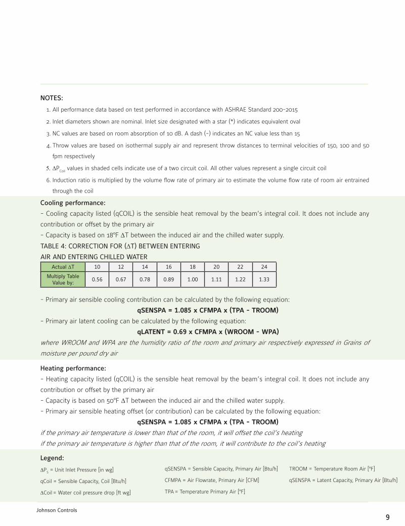
NOTES:
1. All performance data based on test performed in accordance with ASHRAE Standard 200-2015
2. Inlet diameters shown are nominal. Inlet size designated with a star (*) indicates equivalent oval
3. NC values are based on room absorption of 10 dB. A dash (-) indicates an NC value less than 15
4. Throw values are based on isothermal supply air and represent throw distances to terminal velocities of 150, 100 and 50
fpm respectively
5.DPCoil
values in shaded cells indicate use of a two circuit coil. All other values represent a single circuit coil
6. Induction ratio is multiplied by the volume flow rate of primary air to estimate the volume flow rate of room air entrained
through the coil
Cooling performance:
- Cooling capacity listed (qCOIL) is the sensible heat removal by the beam’s integral coil. It does not include any
contribution or offset by the primary air
- Capacity is based on 18BF DT between the induced air and the chilled water supply.
- Primary air sensible cooling contribution can be calculated by the following equation:
qSENSPA = 1.085 x CFMPA x (TPA - TROOM)
- Primary air latent cooling can be calculated by the following equation:
qLATENT = 0.69 x CFMPA x (WROOM - WPA)
where WROOM and WPA are the humidity ratio of the room and primary air respectively expressed in Grains of
moisture per pound dry air
Heating performance:
- Heating capacity listed (qCOIL) is the sensible heat removal by the beam’s integral coil. It does not include any
contribution or offset by the primary air
- Capacity is based on 50BF DT between the induced air and the chilled water supply.
- Primary air sensible heating offset (or contribution) can be calculated by the following equation:
qSENSPA = 1.085 x CFMPA x (TPA - TROOM)
if the primary air temperature is lower than that of the room, it will offset the coil’s heating
if the primary air temperature is higher than that of the room, it will contribute to the coil’s heating
TABLE4:CORRECTIONFOR(DT)BETWEENENTERING
AIRANDENTERINGCHILLEDWATERActual DT 10 12 14 16 18 20 22 24
MultiplyTableValue by:
0.56 0.67 0.78 0.89 1.00 1.11 1.22 1.33
Legend:
DPS = Unit Inlet Pressure [in wg]
qCoil = Sensible Capacity, Coil [Btu/h]
DCoil = Water coil pressure drop [ft wg]
qSENSPA = Sensible Capacity, Primary Air [Btu/h]
CFMPA = Air Flowrate, Primary Air [CFM]
TPA = Temperature Primary Air [BF]
TROOM = Temperature Room Air [BF]
qSENSPA = Latent Capacity, Primary Air [Btu/h]

10Johnson Controls
CB-ABL-YK
DIMENSIONALINFORMATIONCB-ABL-YK (12-INCH)
MODELSPECIFICFEATURES&OPTIONS
• 12 inch and 24 inch widths
• Condensate tray with drain connection for field
plumbing (12 inch version only)

11Johnson Controls
DIMENSIONALINFORMATIONCB-ABL-YK (24-INCH)

12Johnson Controls
CB-ALV-YK:PERFORMANCEDATA(4-PIPECOOLING)
NominalLength
ft
NozzleSize
Primary Air
Sound
NC
CoilSensibleCooling(Btu/h)
Induction ratio
Throw
ft.
Inlet Dia.Flow Rate
Inlet DPS 0.5GPM 1.0GPM 1.5GPM 2.0GPM
Inches CFM (in.H2O) qCOIL DCOIL qCOIL DCOIL qCOIL DCOIL qCOIL DCOIL
4
B1 5
17 0.25 22 2,236
0.72
2,777
2.88
3,004
6.49
3,134
1.10 4.2
0 - 1 - 3
24 0.50 30 2,171 2,697 2,918 3,044 1 - 2 - 7
29 0.75 35 2,923 3,631 3,927 4,097 1 - 3 - 10
B2 5
23 0.25 23 743
0.72
923
2.88
998
6.49
1,041
1.10 3.7
1 - 1 - 5
32 0.50 31 822 1,021 1,104 1,152 1 - 3 - 10
40 0.75 36 1,029 1,278 1,383 1,443 2-4-13
B3 6
48 0.25 26 2,643
0.72
3,283
2.88
3,551
6.49
3,704
1.10 2.7
2-4-12
68 0.50 34 2,620 3,254 3,520 3,672 3-7-16
84 0.75 39 3,486 4,330 4,683 4,886 5 - 11 - 18
B4 8
79 0.25 20 1,775
0.72
2,205
2.88
2,385
6.49
2,489
1.10 1.9
3-6-15
112 0.50 28 1,970 2,446 2,646 2,761 5 - 11 - 18
137 0.75 33 2,463 3,059 3,309 3,452 8-14-20
6
B1 5
25 0.25 25 1,849
1.01
2,297
4.03
2,484
9.06
2,592
2.26 4.2
0-1-4
36 0.50 33 1,920 2,385 2,580 2,692 1 - 2 - 8
44 0.75 38 2,489 3,092 3,344 3,489 1 - 3 - 13
B2 6
39 0.25 24 1,989
1.01
2,471
4.03
2,673
9.06
2,788
2.26 3.7
1 - 2 - 8
55 0.50 32 2,038 2,532 2,739 2,857 2-4-15
67 0.75 36 2,662 3,307 3,577 3,732 3-6-18
B3 8
75 0.25 21 2,333
1.01
2,898
4.03
3,135
9.06
3,270
2.26 2.7
2-5-16
106 0.50 29 2,374 2,949 3,189 3,327 4-9-20
129 0.75 33 3,112 3,866 4,182 4,363 6-14-22
B4 8
136 0.25 26 2,993
1.01
3,718
4.03
4,022
9.06
4,196
2.26 1.9
4-9-20
192 0.50 34 3,039 3,775 4,084 4,260 8-16-24
235 0.75 39 3,989 4,955 5,360 5,592 12-19-26
8
B1 6
30 0.25 20 1,872
1.31
2,325
5.07
2,515
1.44
2,623
2.52 4.2
0-1-4
43 0.50 27 2,250 2,795 3,023 3,154 1 - 2 - 8
53 0.75 32 2,697 3,350 3,624 3,780 1 - 3 - 12
B2 6
46 0.25 23 1,934
1.31
2,403
5.07
2,599
1.44
2,711
2.52 3.7
1 - 2 - 7
65 0.50 31 2,354 2,924 3,163 3,300 2-4-14
79 0.75 36 2,804 3,483 3,767 3,930 2 - 5 - 18
B3 8
88 0.25 20 2,258
1.31
2,805
5.07
3,034
1.44
3,165
2.52 2.7
2-4-16
124 0.50 28 2,736 3,399 3,677 3,836 4-8-21
152 0.75 33 3,266 4,057 4,389 4,578 5-12-24
B4 8
153 0.25 25 2,709
1.31
3,365
5.07
3,640
1.44
3,797
2.52 1.9
3 - 8 - 21
217 0.50 33 3,422 4,251 4,598 4,797 7 - 15 - 25
266 0.75 37 3,999 4,968 5,374 5,606 10 - 19 - 28
10
B1 6
43 0.25 24 2,680
1.65
3,329
6.34
3,601
1.81
3,757
3.22 4.2
1-1-6
61 0.50 32 2,835 3,522 3,809 3,974 1 - 3 - 11
75 0.75 37 3,638 4,519 4,888 5,099 2-4-17
B2 6
65 0.25 28 2,757
1.65
3,424
6.34
3,704
1.81
3,864
3.22 3.7
1 - 3 - 10
92 0.50 36 2,961 3,678 3,978 4,150 2 - 5 - 19
112 0.75 40 3,768 4,680 5,063 5,281 3 - 8 - 23
B3 8
127 0.25 25 3,324
1.65
4,129
6.34
4,467
1.81
4,660
3.22 2.7
3-6-20
179 0.50 33 3,483 4,326 4,679 4,881 5-12-26
219 0.75 38 4,493 5,581 6,037 6,298 8 - 18 - 29
B4 10*
230 0.25 24 4,252
1.65
5,282
6.34
5,713
1.81
5,960
3.22 1.9
5-12-26
325 0.50 32 4,454 5,532 5,984 6,243 11 - 21 - 31
398 0.75 37 5,746 7,138 7,721 8,055 16-24-34

13Johnson Controls
CB-ALV-YK:PERFORMANCEDATA(4-PIPEHEATING)
NominalLength
ft
NozzleSize
Primary Air
Sound
NC
CoilHeating(Btu/h)
Induction ratio
Throw
ft.
Inlet Dia.Flow Rate
Inlet DPS 0.5GPM 1.0GPM 1.5GPM 2.0GPM
Inches CFM (in.H2O) qCOIL DCOIL qCOIL DCOIL qCOIL DCOIL qCOIL DCOIL
4
B1 5
17 0.25 22 3,476
0.18
4,317
0.72
4,670
1.62
4,872
2.88 4.2
0 - 1 - 3
24 0.50 30 3,375 4,193 4,535 4,731 1 - 2 - 7
29 0.75 35 4,544 5,644 6,105 6,369 1 - 3 - 10
B2 5
23 0.25 23 2,154
0.18
2,675
0.72
2,894
1.62
3,019
2.88 3.7
1 - 1 - 5
32 0.50 31 2,383 2,960 3,202 3,341 1 - 3 - 10
40 0.75 36 2,984 3,707 4,010 4,183 2-4-13
B3 6
48 0.25 26 4,108
0.18
5,103
0.72
5,520
1.62
5,758
2.88 2.7
2-4-12
68 0.50 34 4,072 5,059 5,472 5,708 3-7-16
84 0.75 39 5,418 6,730 7,280 7,595 5 - 11 - 18
B4 8
79 0.25 20 3,705
0.18
4,602
0.72
4,978
1.62
5,193
2.88 1.9
3-6-15
112 0.50 28 4,110 5,105 5,523 5,761 5 - 11 - 18
137 0.75 33 5,140 6,384 6,906 7,204 8-14-20
6
B1 5
25 0.25 25 4,249
0.25
5,278
1.01
5,709
2.27
5,955
4.03 4.2
0-1-4
36 0.50 33 4,413 5,481 5,929 6,185 1 - 2 - 8
44 0.75 38 5,720 7,105 7,686 8,018 1 - 3 - 13
B2 6
39 0.25 24 4,571
0.25
5,679
1.01
6,142
2.27
6,408
4.03 3.7
1 - 2 - 8
55 0.50 32 4,684 5,819 6,294 6,566 2-4-15
67 0.75 36 6,118 7,599 8,220 8,575 3-6-18
B3 8
75 0.25 21 5,361
0.25
6,660
1.01
7,204
2.27
7,515
4.03 2.7
2-5-16
106 0.50 29 5,455 6,776 7,329 7,646 4-9-20
129 0.75 33 7,152 8,884 9,610 10,025 6-14-22
B4 8
136 0.25 26 6,861
0.25
8,522
1.01
9,219
2.27
9,617
4.03 1.9
4-9-20
192 0.50 34 6,966 8,653 9,360 9,765 8-16-24
235 0.75 39 9,145 11,359 12,287 12,818 12-19-26
8
B1 6
30 0.25 20 4,301
0.33
5,342
1.27
5,779
2.79
6,028
4.87 4.2
0-1-4
43 0.50 27 5,171 6,423 6,947 7,248 1 - 2 - 8
53 0.75 32 6,198 7,698 8,327 8,687 1 - 3 - 12
B2 6
46 0.25 23 4,445
0.33
5,521
1.27
5,972
2.79
6,230
4.87 3.7
1 - 2 - 7
65 0.50 31 5,410 6,720 7,269 7,583 2-4-14
79 0.75 36 6,443 8,004 8,658 9,032 2 - 5 - 18
B3 8
88 0.25 20 5,189
0.33
6,445
1.27
6,972
2.79
7,273
4.87 2.7
2-4-16
124 0.50 28 6,288 7,811 8,449 8,814 4-8-21
152 0.75 33 7,506 9,324 10,085 10,521 5-12-24
B4 8
153 0.25 25 6,210
0.33
7,714
1.27
8,344
2.79
8,704
4.87 1.9
3 - 8 - 21
217 0.50 33 7,844 9,744 10,540 10,995 7 - 15 - 25
266 0.75 37 9,168 11,388 12,318 12,850 10 - 19 - 28
10
B1 6
43 0.25 24 6,159
0.41
7,650
1.59
8,275
3.49
8,633
6.20 4.2
1-1-6
61 0.50 32 6,515 8,093 8,754 9,132 1 - 3 - 11
75 0.75 37 8,360 10,385 11,233 11,719 2-4-17
B2 6
65 0.25 28 6,335
0.41
7,869
1.59
8,512
3.49
8,880
6.20 3.7
1 - 3 - 10
92 0.50 36 6,803 8,451 9,141 9,536 2 - 5 - 19
112 0.75 40 8,659 10,755 11,634 12,137 3 - 8 - 23
B3 8
127 0.25 25 7,639
0.41
9,489
1.59
10,265
3.49
10,708
6.20 2.7
3-6-20
179 0.50 33 8,003 9,941 10,753 11,218 5-12-26
219 0.75 38 10,325 12,825 13,872 14,472 8 - 18 - 29
B4 10*
230 0.25 24 9,747
0.41
12,107
1.59
13,096
3.49
13,662
6.20 1.9
5-12-26
325 0.50 32 10,209 12,682 13,718 14,310 11 - 21 - 31
398 0.75 37 13,172 16,362 17,698 18,463 16-24-34

14Johnson Controls
CB-ALV-YK:PERFORMANCEDATA(2-PIPECOOLING)
NominalLength
ft
NozzleSize
Primary Air
Sound
NC
CoilSensibleCooling(Btu/h)
Induction ratio
Throw
ft.
Inlet Dia.Flow Rate
Inlet DPS 0.5GPM 1.0GPM 1.5GPM 2.0GPM
Inches CFM (in.H2O) qCOIL DCOIL qCOIL DCOIL qCOIL DCOIL qCOIL DCOIL
4
B1 5
17 0.25 22 2,460
0.87
3,055
3,36
3,305
7.40
3,448
1.67 4.2
0 - 1 - 3
24 0.50 30 2,388 2,967 3,209 3,348 1 - 2 - 7
29 0.75 35 3,215 3,994 4,320 4,507 1 - 3 - 10
B2 5
23 0.25 23 817
0.87
1,015
3,36
1,098
7.40
1,145
1.67 3.7
1 - 1 - 5
32 0.50 31 904 1,123 1,215 1,267 1 - 3 - 10
40 0.75 36 1,132 1,406 1,521 1,587 2-4-13
B3 6
48 0.25 26 2,907
0.87
3,611
3,36
3,906
7.40
4,075
1.67 2.7
2-4-12
68 0.50 34 2,882 3,580 3,872 4,039 3-7-16
84 0.75 39 3,834 4,763 5,152 5,374 5 - 11 - 18
B4 8
79 0.25 20 1,953
0.87
2,426
3,36
2,624
7.40
2,737
1.67 1.9
3-6-15
112 0.50 28 2,166 2,691 2,911 3,037 5 - 11 - 18
137 0.75 33 2,709 3,365 3,640 3,797 8-14-20
6
B1 5
25 0.25 25 2,034
1,31
2,526
5.07
2,733
1.44
2,851
2.52 4.2
0-1-4
36 0.50 33 2,112 2,624 2,838 2,961 1 - 2 - 8
44 0.75 38 2,738 3,401 3,679 3,838 1 - 3 - 13
B2 6
39 0.25 24 2,188
1,31
2,718
5.07
2,940
1.44
3,067
2.52 3.7
1 - 2 - 8
55 0.50 32 2,242 2,785 3,013 3,143 2-4-15
67 0.75 36 2,928 3,638 3,935 4,105 3-6-18
B3 8
75 0.25 21 2,566
1,31
3,188
5.07
3,448
1.44
3,597
2.52 2.7
2-5-16
106 0.50 29 2,611 3,243 3,508 3,660 4-9-20
129 0.75 33 3,424 4,253 4,600 4,799 6-14-22
B4 8
136 0.25 26 3,292
1,31
4,090
5.07
4,424
1.44
4,615
2.52 1.9
4-9-20
192 0.50 34 3,343 4,153 4,492 4,686 8-16-24
235 0.75 39 4,388 5,451 5,896 6,151 12-19-26
8
B1 6
30 0.25 20 2,059
1.76
2,557
6.77
2,766
1.93
2,886
3.38 4.2
0-1-4
43 0.50 27 2,475 3,074 3,326 3,469 1 - 2 - 8
53 0.75 32 2,967 3,685 3,986 4,158 1 - 3 - 12
B2 6
46 0.25 23 2,128
1.76
2,643
6.77
2,859
1.93
2,982
3.38 3.7
1 - 2 - 7
65 0.50 31 2,590 3,217 3,479 3,630 2-4-14
79 0.75 36 3,084 3,831 4,144 4,323 2 - 5 - 18
B3 8
88 0.25 20 2,484
1.76
3,085
6.77
3,337
1.93
3,481
3.38 2.7
2-4-16
124 0.50 28 3,010 3,739 4,044 4,219 4-8-21
152 0.75 33 3,593 4,463 4,828 5,036 5-12-24
B4 8
153 0.25 25 2,980
1.76
3,702
6.77
4,004
1.93
4,177
3.38 1.9
3 - 8 - 21
217 0.50 33 3,764 4,676 5,058 5,276 7 - 15 - 25
266 0.75 37 4,399 5,465 5,911 6,167 10 - 19 - 28
10
B1 6
43 0.25 24 2,948
2.20
3,662
8.47
3,961
2.42
4,132
4.24 4.2
1-1-6
61 0.50 32 3,119 3,874 4,190 4,371 1 - 3 - 11
75 0.75 37 4,002 4,971 5,377 5,609 2-4-17
B2 6
65 0.25 28 3,033
2.20
3,767
8.47
4,075
2.42
4,251
4.24 3.7
1 - 3 - 10
92 0.50 36 3,257 4,045 4,376 4,565 2 - 5 - 19
112 0.75 40 4,145 5,148 5,569 5,810 3 - 8 - 23
B3 8
127 0.25 25 3,657
2.20
4,542
8.47
4,913
2.42
5,126
4.24 2.7
3-6-20
179 0.50 33 3,831 4,758 5,147 5,370 5-12-26
219 0.75 38 4,942 6,139 6,640 6,927 8 - 18 - 29
B4 10*
230 0.25 24 4,677
2.20
5,810
8.47
6,285
2.42
6,556
4.24 1.9
5-12-26
325 0.50 32 4,899 6,086 6,583 6,867 11 - 21 - 31
398 0.75 37 6,321 7,852 8,493 8,860 16-24-34

15Johnson Controls
CB-ALV-YK:PERFORMANCEDATA(2-PIPEHEATING)
NominalLength
ft
NozzleSize
Primary Air
Sound
NC
CoilHeating(Btu/h)
Induction ratio
Throw
ft.
Inlet Dia.Flow Rate
Inlet DPS 0.5GPM 1.0GPM 1.5GPM 2.0GPM
Inches CFM (in.H2O) qCOIL DCOIL qCOIL DCOIL qCOIL DCOIL qCOIL DCOIL
4
B1 5
17 0.25 22 4,692
0.72
5,829
2.90
6,305
6.52
6,577
1.51 4.2
0 - 1 - 3
24 0.50 30 4,557 5,660 6,122 6,387 1 - 2 - 7
29 0.75 35 6,134 7,619 8,242 8,598 1 - 3 - 10
B2 5
23 0.25 23 2,908
0.72
3,612
2.90
3,907
6.52
4,076
1.51 3.7
1 - 1 - 5
32 0.50 31 3,217 3,996 4,323 4,510 1 - 3 - 10
40 0.75 36 4,029 5,004 5,413 5,647 2-4-13
B3 6
48 0.25 26 5,546
0.72
6,889
2.90
7,452
6.52
7,774
1.51 2.7
2-4-12
68 0.50 34 5,498 6,829 7,387 7,706 3-7-16
84 0.75 39 7,315 9,086 9,828 10,253 5 - 11 - 18
B4 8
79 0.25 20 5,002
0.72
6,213
2.90
6,721
6.52
7,011
1.51 1.9
3-6-15
112 0.50 28 5,549 6,892 7,455 7,778 5 - 11 - 18
137 0.75 33 6,939 8,619 9,323 9,726 8-14-20
6
B1 5
25 0.25 25 5,736
1.05
7,125
4.20
7,707
1.23
8,040
2.19 4.2
0-1-4
36 0.50 33 5,957 7,400 8,004 8,350 1 - 2 - 8
44 0.75 38 7,722 9,592 10,375 10,824 1 - 3 - 13
B2 6
39 0.25 24 6,172
1.05
7,666
4.20
8,292
1.23
8,651
2.19 3.7
1 - 2 - 8
55 0.50 32 6,324 7,855 8,497 8,864 2-4-15
67 0.75 36 8,259 10,259 11,097 11,577 3-6-18
B3 8
75 0.25 21 7,238
1.05
8,990
4.20
9,725
1.23
10,145
2.19 2.7
2-5-16
106 0.50 29 7,364 9,147 9,895 10,322 4-9-20
129 0.75 33 9,655 11,994 12,973 13,534 6-14-22
B4 8
136 0.25 26 9,262
1.05
11,505
4.20
12,445
1.23
12,983
2.19 1.9
4-9-20
192 0.50 34 9,405 11,682 12,636 13,183 8-16-24
235 0.75 39 12,345 15,335 16,587 17,304 12-19-26
8
B1 6
30 0.25 20 5,806
1.76
7,212
6.77
7,801
1.61
8,138
2.86 4.2
0-1-4
43 0.50 27 6,980 8,671 9,379 9,784 1 - 2 - 8
53 0.75 32 8,367 10,393 11,242 11,728 1 - 3 - 12
B2 6
46 0.25 23 6,000
1.76
7,454
6.77
8,062
1.61
8,411
2.86 3.7
1 - 2 - 7
65 0.50 31 7,303 9,072 9,813 10,237 2-4-14
79 0.75 36 8,699 10,805 11,688 12,193 2 - 5 - 18
B3 8
88 0.25 20 7,005
1.76
8,701
6.77
9,412
1.61
9,819
2.86 2.7
2-4-16
124 0.50 28 8,489 10,545 11,406 11,899 4-8-21
152 0.75 33 10,133 12,587 13,615 14,204 5-12-24
B4 8
153 0.25 25 8,383
1.76
10,413
6.77
11,264
1.61
11,751
2.86 1.9
3 - 8 - 21
217 0.50 33 10,590 13,154 14,229 14,844 7 - 15 - 25
266 0.75 37 12,376 15,373 16,629 17,348 10 - 19 - 28
10
B1 6
43 0.25 24 8,314
2.20
10,328
8.47
11,171
2.03
11,654
3.61 4.2
1-1-6
61 0.50 32 8,796 10,926 11,818 12,329 1 - 3 - 11
75 0.75 37 11,286 14,019 15,165 15,820 2-4-17
B2 6
65 0.25 28 8,553
2.20
10,624
8.47
11,492
2.03
11,988
3.61 3.7
1 - 3 - 10
92 0.50 36 9,185 11,409 12,341 12,874 2 - 5 - 19
112 0.75 40 11,689 14,520 15,706 16,385 3 - 8 - 23
B3 8
127 0.25 25 10,313
2.20
12,811
8.47
13,857
2.03
14,456
3.61 2.7
3-6-20
179 0.50 33 10,804 13,420 14,517 15,144 5-12-26
219 0.75 38 13,938 17,313 18,728 19,537 8 - 18 - 29
B4 10*
230 0.25 24 13,158
2.20
16,345
8.47
17,680
2.03
18,444
3.61 1.9
5-12-26
325 0.50 32 13,783 17,120 18,519 19,319 11 - 21 - 31
398 0.75 37 17,782 22,088 23,893 24,925 16-24-34

16Johnson Controls
NOTES:
1. All performance data based on test performed in accordance with ASHRAE Standard 200-2015
2. Inlet diameters shown are nominal. Inlet size designated with a star (*) indicates equivalent oval
3. NC values are based on room absorption of 10 dB. A dash (-) indicates an NC value less than 15
4. Throw values are based on isothermal supply air and represent throw distances to terminal velocities of 150, 100 and 50
fpm respectively
5.DPCoil
values in shaded cells indicate use of a two circuit coil. All other values represent a single circuit coil
6. Induction ratio is multiplied by the volume flow rate of primary air to estimate the volume flow rate of room air entrained
through the coil
Cooling performance:
- Cooling capacity listed (qCOIL) is the sensible heat removal by the beam’s integral coil. It does not include any
contribution or offset by the primary air
- Capacity is based on 18BF DT between the induced air and the chilled water supply.
- Primary air sensible cooling contribution can be calculated by the following equation:
qSENSPA = 1.085 x CFMPA x (TPA - TROOM)
- Primary air latent cooling can be calculated by the following equation:
qLATENT = 0.69 x CFMPA x (WROOM - WPA)
where WROOM and WPA are the humidity ratio of the room and primary air respectively expressed in Grains of
moisture per pound dry air
Heating performance:
- Heating capacity listed (qCOIL) is the sensible heat removal by the beam’s integral coil. It does not include any
contribution or offset by the primary air
- Capacity is based on 50BF DT between the induced air and the chilled water supply.
- Primary air sensible heating offset (or contribution) can be calculated by the following equation:
qSENSPA = 1.085 x CFMPA x (TPA - TROOM)
if the primary air temperature is lower than that of the room, it will offset the coil’s heating
if the primary air temperature is higher than that of the room, it will contribute to the coil’s heating
TABLE4:CORRECTIONFOR(DT)BETWEENENTERING
AIRANDENTERINGCHILLEDWATERActual DT 10 12 14 16 18 20 22 24
MultiplyTableValue by:
0.56 0.67 0.78 0.89 1.00 1.11 1.22 1.33
Legend:
DPS = Unit Inlet Pressure [in wg]
qCoil = Sensible Capacity, Coil [Btu/h]
DCoil = Water coil pressure drop [ft wg]
qSENSPA = Sensible Capacity, Primary Air [Btu/h]
CFMPA = Air Flowrate, Primary Air [CFM]
TPA = Temperature Primary Air [BF]
TROOM = Temperature Room Air [BF]
qSENSPA = Latent Capacity, Primary Air [Btu/h]

17Johnson Controls
CB-ALV-YK
DIMENSIONALINFORMATIONCB-ALV-YK
MODELSPECIFICFEATURES&OPTIONS
• Vertical Water Coil
• Condensate tray with drain connection for field
plumbing

18Johnson Controls
CB-ALE-YK:24-INWIDTH:PERFORMANCEDATA(4-PIPECOOLING)
NominalLength
ft
NozzleSize
Primary Air
Sound
NC
CoilSensibleCooling(Btu/h)
Induction ratio
Throw
ft.
Inlet Dia.Flow Rate
Inlet DPS 0.5GPM 1.0GPM 1.5GPM 2.0GPM
Inches CFM (in.H2O) qCOIL DCOIL qCOIL DCOIL qCOIL DCOIL qCOIL DCOIL
4
B1 4
17 0.25 - 1,895
0.72
2,354
2.88
2,546
6.49
2,656
1.10 5.9
0 - 1 - 3
24 0.50 - 2,043 2,537 2,745 2,863 1 - 2 - 5
29 0.75 16 2,594 3,222 3,486 3,636 1 - 3 - 7
B2 4
25 0.25 - 1,955
0.72
2,429
2.88
2,627
6.49
2,741
1.10 4.8
1-1-4
36 0.50 19 2,136 2,653 2,869 2,993 1 - 3 - 7
44 0.75 24 2,693 3,345 3,619 3,775 2-4-10
B3 5
48 0.25 17 2,240
0.72
2,782
2.88
3,009
6.49
3,140
1.10 4
2 - 3 - 9
68 0.50 26 2,466 3,063 3,313 3,456 4-6-13
84 0.75 31 3,096 3,846 4,160 4,340 7 - 9 - 15
B4 6
87 0.25 25 2,519
0.72
3,129
2.88
3,384
6.49
3,531
1.10 2.5
2 - 5 - 10
124 0.50 34 2,774 3,445 3,727 3,888 6-8-14
151 0.75 39 3,482 4,326 4,679 4,881 10 - 10 - 17
6
B1 4
25 0.25 - 2,335
1.01
2,900
4.03
3,137
9.06
3,273
2.26 5.9
0 - 1 - 3
36 0.50 19 2,594 3,222 3,485 3,636 1 - 2 - 7
44 0.75 24 3,241 4,026 4,355 4,543 2 - 3 - 10
B2 5
39 0.25 - 2,512
1.01
3,120
4.03
3,375
9.06
3,521
2.26 4.8
1 - 2 - 5
55 0.50 22 2,753 3,420 3,699 3,859 2 - 3 - 9
67 0.75 27 3,465 4,305 4,656 4,857 3 - 5 - 12
B3 6
75 0.25 21 2,946
1.01
3,659
4.03
3,958
9.06
4,129
2.26 4
2-4-10
106 0.50 30 3,206 3,982 4,307 4,494 5 - 7 - 15
129 0.75 36 4,051 5,031 5,443 5,678 8 - 10 - 19
B4 8
136 0.25 26 3,337
1.01
4,145
4.03
4,484
9.06
4,677
2.26 2.5
3 - 5 - 13
192 0.50 35 3,624 4,501 4,869 5,080 7 - 10 - 18
235 0.75 40 4,584 5,694 6,159 6,425 12 - 13 - 21
8
B1 4
30 0.25 - 2,431
1.32
3,020
5.28
3,267
1.54
3,408
2.74 5.9
0 - 1 - 3
43 0.50 22 3,074 3,819 4,131 4,309 1 - 2 - 7
53 0.75 27 3,591 4,461 4,825 5,034 2-4-12
B2 5
46 0.25 15 2,513
1.32
3,121
5.28
3,376
1.54
3,522
2.74 4.8
1 - 2 - 5
65 0.50 24 3,217 3,996 4,323 4,509 2 - 3 - 10
79 0.75 30 3,735 4,639 5,018 5,235 3-5-14
B3 8
88 0.25 16 2,933
1.32
3,644
5.28
3,941
1.54
4,112
2.74 4
2-4-12
124 0.50 25 3,739 4,645 5,024 5,241 5 - 9 - 18
152 0.75 30 4,350 5,404 5,845 6,098 9 - 12 - 21
B4 10*
153 0.25 22 3,108
1.32
3,860
5.28
4,176
1.54
4,356
2.74 2.5
4-6-15
217 0.50 31 4,130 5,131 5,550 5,790 8 - 12 - 21
266 0.75 36 4,707 5,846 6,324 6,597 14-15-24
10
B1 5
43 0.25 15 3,538
1.63
4,394
6.53
4,753
1.91
4,959
3.40 5.9
1-1-4
61 0.50 24 3,892 4,835 5,230 5,456 1 - 3 - 9
75 0.75 29 4,889 6,073 6,569 6,853 2-4-13
B2 6
65 0.25 18 3,639
1.63
4,520
6.53
4,890
1.91
5,101
3.40 4.8
1 - 2 - 7
92 0.50 27 4,065 5,049 5,462 5,698 2-4-12
112 0.75 33 5,064 6,291 6,805 7,099 4-7-16
B3 8
127 0.25 25 4,388
1.63
5,450
6.53
5,896
1.91
6,150
3.40 4
3 - 5 - 13
179 0.50 34 4,781 5,938 6,423 6,701 6-10-20
219 0.75 39 6,037 7,499 8,111 8,462 10-13-24
B4 10*
230 0.25 31 4,955
1.63
6,155
6.53
6,658
1.91
6,946
3.40 2.5
4-7-17
325 0.50 40 5,398 6,706 7,253 7,567 9 - 12 - 23
398 0.75 45 6,817 8,468 9,160 9,556 15-17-26
19Johnson Controls
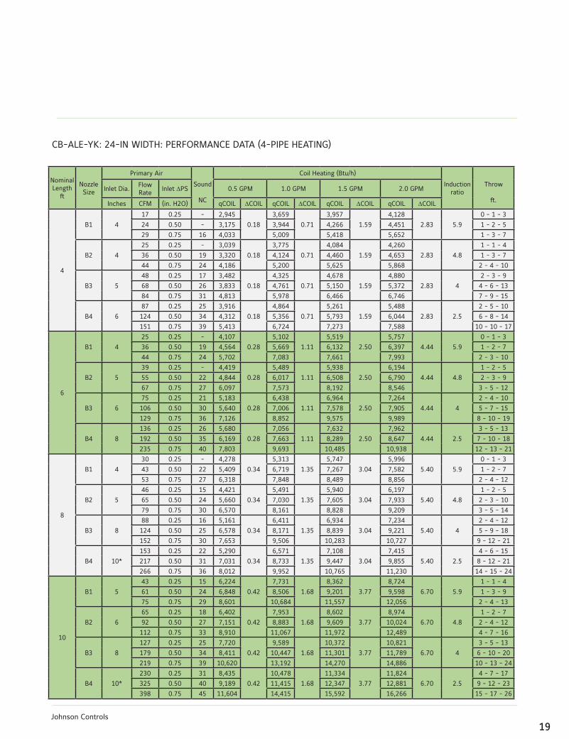
CB-ALE-YK:24-INWIDTH:PERFORMANCEDATA(4-PIPEHEATING)
NominalLength
ft
NozzleSize
Primary Air
Sound
NC
CoilHeating(Btu/h)
Induction ratio
Throw
ft.
Inlet Dia.Flow Rate
Inlet DPS 0.5GPM 1.0GPM 1.5GPM 2.0GPM
Inches CFM (in.H2O) qCOIL DCOIL qCOIL DCOIL qCOIL DCOIL qCOIL DCOIL
4
B1 4
17 0.25 - 2,945
0.18
3,659
0.71
3,957
1.59
4,128
2.83 5.9
0 - 1 - 3
24 0.50 - 3,175 3,944 4,266 4,451 1 - 2 - 5
29 0.75 16 4,033 5,009 5,418 5,652 1 - 3 - 7
B2 4
25 0.25 - 3,039
0.18
3,775
0.71
4,084
1.59
4,260
2.83 4.8
1-1-4
36 0.50 19 3,320 4,124 4,460 4,653 1 - 3 - 7
44 0.75 24 4,186 5,200 5,625 5,868 2-4-10
B3 5
48 0.25 17 3,482
0.18
4,325
0.71
4,678
1.59
4,880
2.83 4
2 - 3 - 9
68 0.50 26 3,833 4,761 5,150 5,372 4-6-13
84 0.75 31 4,813 5,978 6,466 6,746 7 - 9 - 15
B4 6
87 0.25 25 3,916
0.18
4,864
0.71
5,261
1.59
5,488
2.83 2.5
2 - 5 - 10
124 0.50 34 4,312 5,356 5,793 6,044 6-8-14
151 0.75 39 5,413 6,724 7,273 7,588 10 - 10 - 17
6
B1 4
25 0.25 - 4,107
0.28
5,102
1.11
5,519
2.50
5,757
4.44 5.9
0 - 1 - 3
36 0.50 19 4,564 5,669 6,132 6,397 1 - 2 - 7
44 0.75 24 5,702 7,083 7,661 7,993 2 - 3 - 10
B2 5
39 0.25 - 4,419
0.28
5,489
1.11
5,938
2.50
6,194
4.44 4.8
1 - 2 - 5
55 0.50 22 4,844 6,017 6,508 6,790 2 - 3 - 9
67 0.75 27 6,097 7,573 8,192 8,546 3 - 5 - 12
B3 6
75 0.25 21 5,183
0.28
6,438
1.11
6,964
2.50
7,264
4.44 4
2-4-10
106 0.50 30 5,640 7,006 7,578 7,905 5 - 7 - 15
129 0.75 36 7,126 8,852 9,575 9,989 8 - 10 - 19
B4 8
136 0.25 26 5,680
0.28
7,056
1.11
7,632
2.50
7,962
4.44 2.5
3 - 5 - 13
192 0.50 35 6,169 7,663 8,289 8,647 7 - 10 - 18
235 0.75 40 7,803 9,693 10,485 10,938 12 - 13 - 21
8
B1 4
30 0.25 - 4,278
0.34
5,313
1.35
5,747
3.04
5,996
5.40 5.9
0 - 1 - 3
43 0.50 22 5,409 6,719 7,267 7,582 1 - 2 - 7
53 0.75 27 6,318 7,848 8,489 8,856 2-4-12
B2 5
46 0.25 15 4,421
0.34
5,491
1.35
5,940
3.04
6,197
5.40 4.8
1 - 2 - 5
65 0.50 24 5,660 7,030 7,605 7,933 2 - 3 - 10
79 0.75 30 6,570 8,161 8,828 9,209 3-5-14
B3 8
88 0.25 16 5,161
0.34
6,411
1.35
6,934
3.04
7,234
5.40 4
2-4-12
124 0.50 25 6,578 8,171 8,839 9,221 5 - 9 - 18
152 0.75 30 7,653 9,506 10,283 10,727 9 - 12 - 21
B4 10*
153 0.25 22 5,290
0.34
6,571
1.35
7,108
3.04
7,415
5.40 2.5
4-6-15
217 0.50 31 7,031 8,733 9,447 9,855 8 - 12 - 21
266 0.75 36 8,012 9,952 10,765 11,230 14-15-24
10
B1 5
43 0.25 15 6,224
0.42
7,731
1.68
8,362
3.77
8,724
6.70 5.9
1-1-4
61 0.50 24 6,848 8,506 9,201 9,598 1 - 3 - 9
75 0.75 29 8,601 10,684 11,557 12,056 2-4-13
B2 6
65 0.25 18 6,402
0.42
7,953
1.68
8,602
3.77
8,974
6.70 4.8
1 - 2 - 7
92 0.50 27 7,151 8,883 9,609 10,024 2-4-12
112 0.75 33 8,910 11,067 11,972 12,489 4-7-16
B3 8
127 0.25 25 7,720
0.42
9,589
1.68
10,372
3.77
10,821
6.70 4
3 - 5 - 13
179 0.50 34 8,411 10,447 11,301 11,789 6-10-20
219 0.75 39 10,620 13,192 14,270 14,886 10-13-24
B4 10*
230 0.25 31 8,435
0.42
10,478
1.68
11,334
3.77
11,824
6.70 2.5
4-7-17
325 0.50 40 9,189 11,415 12,347 12,881 9 - 12 - 23
398 0.75 45 11,604 14,415 15,592 16,266 15-17-26

20Johnson Controls
CB-ALE-YK:24-INWIDTH:PERFORMANCEDATA(2-PIPECOOLING)
NominalLength
ft
NozzleSize
Primary Air
Sound
NC
CoilSensibleCooling(Btu/h)
Induction ratio
Throw
ft.
Inlet Dia.Flow Rate
Inlet DPS 0.5GPM 1.0GPM 1.5GPM 2.0GPM
Inches CFM (in.H2O) qCOIL DCOIL qCOIL DCOIL qCOIL DCOIL qCOIL DCOIL
4
B1 4
17 0.25 - 2,084
0.93
2,589
3.72
2,800
8.38
2,921
1.92 5.9
0 - 1 - 3
24 0.50 - 2,247 2,791 3,019 3,150 1 - 2 - 5
29 0.75 16 2,854 3,545 3,834 4,000 1 - 3 - 7
B2 4
25 0.25 - 2,151
0.93
2,672
3.72
2,890
8.38
3,015
1.92 4.8
1-1-4
36 0.50 19 2,349 2,918 3,156 3,293 1 - 3 - 7
44 0.75 24 2,962 3,680 3,980 4,152 2-4-10
B3 5
48 0.25 17 2,464
0.93
3,060
3.72
3,310
8.38
3,453
1.92 4
2 - 3 - 9
68 0.50 26 2,712 3,369 3,644 3,802 4-6-13
84 0.75 31 3,406 4,230 4,576 4,774 7 - 9 - 15
B4 6
87 0.25 25 2,771
0.93
3,442
3.72
3,723
8.38
3,884
1.92 2.5
2 - 5 - 10
124 0.50 34 3,051 3,790 4,100 4,277 6-8-14
151 0.75 39 3,831 4,758 5,147 5,369 10 - 10 - 17
6
B1 4
25 0.25 - 2,568
1.35
3,190
5.40
3,451
1.58
3,600
2.81 5.9
0 - 1 - 3
36 0.50 19 2,853 3,544 3,834 4,000 1 - 2 - 7
44 0.75 24 3,565 4,429 4,790 4,997 2 - 3 - 10
B2 5
39 0.25 - 2,763
1.35
3,432
5.40
3,713
1.58
3,873
2.81 4.8
1 - 2 - 5
55 0.50 22 3,029 3,762 4,069 4,245 2 - 3 - 9
67 0.75 27 3,812 4,735 5,122 5,343 3 - 5 - 12
B3 6
75 0.25 21 3,240
1.35
4,025
5.40
4,354
1.58
4,542
2.81 4
2-4-10
106 0.50 30 3,526 4,380 4,738 4,943 5 - 7 - 15
129 0.75 36 4,456 5,535 5,987 6,245 8 - 10 - 19
B4 8
136 0.25 26 3,671
1.35
4,559
5.40
4,932
1.58
5,145
2.81 2.5
3 - 5 - 13
192 0.50 35 3,986 4,952 5,356 5,588 7 - 10 - 18
235 0.75 40 5,042 6,263 6,775 7,068 12 - 13 - 21
8
B1 4
30 0.25 - 2,675
1.77
3,322
7.08
3,594
2.07
3,749
3.68 5.9
0 - 1 - 3
43 0.50 22 3,382 4,201 4,544 4,740 1 - 2 - 7
53 0.75 27 3,950 4,907 5,308 5,537 2-4-12
B2 5
46 0.25 15 2,764
1.77
3,433
7.08
3,714
2.07
3,874
3.68 4.8
1 - 2 - 5
65 0.50 24 3,539 4,396 4,755 4,960 2 - 3 - 10
79 0.75 30 4,108 5,103 5,520 5,758 3-5-14
B3 8
88 0.25 16 3,227
1.77
4,008
7.08
4,336
2.07
4,523
3.68 4
2-4-12
124 0.50 25 4,113 5,109 5,526 5,765 5 - 9 - 18
152 0.75 30 4,785 5,944 6,430 6,707 9 - 12 - 21
B4 10*
153 0.25 22 3,419
1.77
4,246
7.08
4,593
2.07
4,792
3.68 2.5
4-6-15
217 0.50 31 4,543 5,644 6,105 6,368 8 - 12 - 21
266 0.75 36 5,177 6,431 6,956 7,257 14-15-24
10
B1 5
43 0.25 15 3,891
2.19
4,834
8.76
5,228
2.56
5,454
4.55 5.9
1-1-4
61 0.50 24 4,282 5,318 5,753 6,001 1 - 3 - 9
75 0.75 29 5,378 6,680 7,226 7,538 2-4-13
B2 6
65 0.25 18 4,003
2.19
4,972
8.76
5,379
2.56
5,611
4.55 4.8
1 - 2 - 7
92 0.50 27 4,471 5,554 6,008 6,268 2-4-12
112 0.75 33 5,571 6,920 7,485 7,809 4-7-16
B3 8
127 0.25 25 4,827
2.19
5,995
8.76
6,485
2.56
6,766
4.55 4
3 - 5 - 13
179 0.50 34 5,259 6,532 7,066 7,371 6-10-20
219 0.75 39 6,640 8,248 8,922 9,308 10-13-24
B4 10*
230 0.25 31 5,451
2.19
6,771
8.76
7,324
2.56
7,641
4.55 2.5
4-7-17
325 0.50 40 5,938 7,376 7,979 8,324 9 - 12 - 23
398 0.75 45 7,499 9,315 10,076 10,511 15-17-26

21Johnson Controls
CB-ALE-YK:24-INWIDTH:PERFORMANCEDATA(2-PIPEHEATING)
NominalLength
ft
NozzleSize
Primary Air
Sound
NC
CoilHeating(Btu/h)
Induction ratio
Throw
ft.
Inlet Dia.Flow Rate
Inlet DPS 0.5GPM 1.0GPM 1.5GPM 2.0GPM
Inches CFM (in.H2O) qCOIL DCOIL qCOIL DCOIL qCOIL DCOIL qCOIL DCOIL
4
B1 4
17 0.25 - 3,976
0.72
4,939
2.90
5,343
6.52
5,573
1.51 5.9
0 - 1 - 3
24 0.50 - 4,287 5,325 5,760 6,009 1 - 2 - 5
29 0.75 16 5,444 6,762 7,315 7,631 1 - 3 - 7
B2 4
25 0.25 - 4,103
0.72
5,097
2.90
5,513
6.52
5,751
1.51 4.8
1-1-4
36 0.50 19 4,482 5,567 6,022 6,282 1 - 3 - 7
44 0.75 24 5,651 7,020 7,593 7,922 2-4-10
B3 5
48 0.25 17 4,700
0.72
5,838
2.90
6,315
6.52
6,588
1.51 4
2 - 3 - 9
68 0.50 26 5,174 6,427 6,952 7,252 4-6-13
84 0.75 31 6,497 8,070 8,730 9,107 7 - 9 - 15
B4 6
87 0.25 25 5,286
0.72
6,566
2.90
7,102
6.52
7,409
1.51 2.5
2 - 5 - 10
124 0.50 34 5,821 7,230 7,821 8,159 6-8-14
151 0.75 39 7,308 9,077 9,819 10,243 10 - 10 - 17
6
B1 4
25 0.25 - 5,545
1.05
6,888
4.20
7,451
1.23
7,772
2.19 5.9
0 - 1 - 3
36 0.50 19 6,161 7,653 8,278 8,636 1 - 2 - 7
44 0.75 24 7,698 9,562 10,343 10,790 2 - 3 - 10
B2 5
39 0.25 - 5,966
1.05
7,411
4.20
8,016
1.23
8,363
2.19 4.8
1 - 2 - 5
55 0.50 22 6,539 8,123 8,786 9,166 2 - 3 - 9
67 0.75 27 8,230 10,223 11,059 11,537 3 - 5 - 12
B3 6
75 0.25 21 6,996
1.05
8,691
4.20
9,401
1.23
9,807
2.19 4
2-4-10
106 0.50 30 7,614 9,458 10,230 10,672 5 - 7 - 15
129 0.75 36 9,620 11,950 12,926 13,485 8 - 10 - 19
B4 8
136 0.25 26 7,668
1.05
9,525
4.20
10,303
1.23
10,749
2.19 2.5
3 - 5 - 13
192 0.50 35 8,328 10,345 11,190 11,673 7 - 10 - 18
235 0.75 40 10,534 13,085 14,154 14,766 12 - 13 - 21
8
B1 4
30 0.25 - 5,775
1.77
7,173
7.08
7,759
1.61
8,094
2.86 5.9
0 - 1 - 3
43 0.50 22 7,302 9,070 9,811 10,235 1 - 2 - 7
53 0.75 27 8,529 10,595 11,460 11,956 2-4-12
B2 5
46 0.25 15 5,968
1.77
7,413
7.08
8,019
1.61
8,366
2.86 4.8
1 - 2 - 5
65 0.50 24 7,641 9,491 10,266 10,710 2 - 3 - 10
79 0.75 30 8,870 11,017 11,918 12,433 3-5-14
B3 8
88 0.25 16 6,967
1.77
8,654
7.08
9,361
1.61
9,766
2.86 4
2-4-12
124 0.50 25 8,881 11,031 11,932 12,448 5 - 9 - 18
152 0.75 30 10,332 12,834 13,882 14,482 9 - 12 - 21
B4 10*
153 0.25 22 7,142
1.77
8,871
7.08
9,596
1.61
10,011
2.86 2.5
4-6-15
217 0.50 31 9,492 11,790 12,753 13,305 8 - 12 - 21
266 0.75 36 10,816 13,435 14,533 15,161 14-15-24
10
B1 5
43 0.25 15 8,402
2.19
10,436
8.76
11,289
2.03
11,777
3.61 5.9
1-1-4
61 0.50 24 9,244 11,483 12,421 12,958 1 - 3 - 9
75 0.75 29 11,611 14,423 15,601 16,276 2-4-13
B2 6
65 0.25 18 8,643
2.19
10,736
8.76
11,613
2.03
12,115
3.61 4.8
1 - 2 - 7
92 0.50 27 9,654 11,992 12,972 13,532 2-4-12
112 0.75 33 12,028 14,941 16,162 16,860 4-7-16
B3 8
127 0.25 25 10,421
2.19
12,945
8.76
14,003
2.03
14,608
3.61 4
3 - 5 - 13
179 0.50 34 11,354 14,104 15,256 15,915 6-10-20
219 0.75 39 14,337 17,809 19,264 20,097 10-13-24
B4 10*
230 0.25 31 11,388
2.19
14,146
8.76
15,301
2.03
15,962
3.61 2.5
4-7-17
325 0.50 40 12,406 15,410 16,669 17,389 9 - 12 - 23
398 0.75 45 15,666 19,460 21,049 21,959 15-17-26

22Johnson Controls
NOTES:
1. All performance data based on test performed in accordance with ASHRAE Standard 200-2015
2. Inlet diameters shown are nominal. Inlet size designated with a star (*) indicates equivalent oval
3. NC values are based on room absorption of 10 dB. A dash (-) indicates an NC value less than 15
4. Throw values are based on isothermal supply air and represent throw distances to terminal velocities of 150, 100 and 50
fpm respectively
5.DPCoil
values in shaded cells indicate use of a two circuit coil. All other values represent a single circuit coil
6. Induction ratio is multiplied by the volume flow rate of primary air to estimate the volume flow rate of room air entrained
through the coil
Cooling performance:
- Cooling capacity listed (qCOIL) is the sensible heat removal by the beam’s integral coil. It does not include any
contribution or offset by the primary air
- Capacity is based on 18BF DT between the induced air and the chilled water supply.
- Primary air sensible cooling contribution can be calculated by the following equation:
qSENSPA = 1.085 x CFMPA x (TPA - TROOM)
- Primary air latent cooling can be calculated by the following equation:
qLATENT = 0.69 x CFMPA x (WROOM - WPA)
where WROOM and WPA are the humidity ratio of the room and primary air respectively expressed in Grains of
moisture per pound dry air
Heating performance:
- Heating capacity listed (qCOIL) is the sensible heat removal by the beam’s integral coil. It does not include any
contribution or offset by the primary air
- Capacity is based on 50BF DT between the induced air and the chilled water supply.
- Primary air sensible heating offset (or contribution) can be calculated by the following equation:
qSENSPA = 1.085 x CFMPA x (TPA - TROOM)
if the primary air temperature is lower than that of the room, it will offset the coil’s heating
if the primary air temperature is higher than that of the room, it will contribute to the coil’s heating
TABLE4:CORRECTIONFOR(DT)BETWEENENTERING
AIRANDENTERINGCHILLEDWATERActual DT 10 12 14 16 18 20 22 24
MultiplyTableValue by:
0.56 0.67 0.78 0.89 1.00 1.11 1.22 1.33
Legend:
DPS = Unit Inlet Pressure [in wg]
qCoil = Sensible Capacity, Coil [Btu/h]
DCoil = Water coil pressure drop [ft wg]
qSENSPA = Sensible Capacity, Primary Air [Btu/h]
CFMPA = Air Flowrate, Primary Air [CFM]
TPA = Temperature Primary Air [BF]
TROOM = Temperature Room Air [BF]
qSENSPA = Latent Capacity, Primary Air [Btu/h]

23Johnson Controls
CB-ALE-YK
DIMENSIONALINFORMATIONCB-ALE-YK
MODELSPECIFICFEATURES&OPTIONS
• Integral coanda plates for ceiling independent air
distribution pattern
• 1-way or 2-way air distribution pattern

24Johnson Controls
Guide Specification:CB-ABL-YK Active Chilled Beams24-inch Width
PART 1- GENERAL
1.01 Summary
This section describes the active chilled beams.
1.02 Submittals
Submit product data for all items complete with the
following information:
1. Operating weights and dimensions of all unit
assemblies.
2. Performance data, including sensible and latent
cooling capacities, nozzle types, primary and total supply
(primary plus induced) airflow rates, chilled (and where
applicable hot) water flow rates, noise levels in octave
bands, air and water side pressure losses and maximum
discharge air throw values.
3. Construction details including manufacturers
recommendations for installation, mounting and
connection.
PART 2- PRODUCTS
2.01 General
Materials and products required for the work of this
section shall not contain asbestos, polychlorinated
biphenyls (PCB) or other hazardous materials identified
by the engineer or owner.
2.02 Design
1. Furnish and install YORK® CB-ABL-YK series two slot
active chilled beams of sizes and capacities as indicated
on the drawings and within the mechanical equipment
schedules. The quantity and length of the beams shall
be as shown on the drawings, without EXCEPTION. The
beams shall be constructed and delivered to the job site
as single units.
2. The face of the beam shall consist of a room air
induction section of 50% free area perforated (optional
linear bar type) induction section flanked by linear supply
slots. The face section shall include hinged fastening on
each side that allows the face to be swung opened from
either direction for coil cleaning. Faces that are designed
to be lifted out are NOT ACCEPTABLE. The entire visible
face sections and all visible internal surfaces shall be
finished in white powder coat paint or as specified by the
architect.
3. Beams shall be provided with side and end details
which will allow its integration into the applicable
(nominal 24 inch wide) acoustical ceiling grid as specified
by the architect.
4. The beams shall consist of a minimum 20 gauge
galvanized steel housing encasing the integral sensible
cooling coil and a plenum feeing a series of induction
nozzles. A single duct connection shall be provided on
either the side or top of the unit. The use of multiple duct
connections is NOT ACCEPTABLE.
5. Each beam shall be provided with a pressure tap
that may be used to measure the pressure differential
between the primary air plenum and the room. Airflow
calibration charts that relate this pressure differential
reading with the primary and beam supply airflow rates
shall be furnished with the beams.
6. Beams shall be provided with connections for either
2 or 4 pipe water connections as indicated on plans
and schedules. Four pipe configurations shall require
separate supply and return connections for chilled and
hot water. The coil shall be mounted horizontally and
shall be manufactured with seamless copper tubing (½”
outside diameter) with minimum .016 inch wall thickness
25Johnson Controls
mechanically fixed to aluminum fins. The aluminum fins
shall be limited to no more than ten (10) fins per inch.
The coil shall have a working pressure of at least 300
PSI, and be factory tested for leakage at a minimum
pressure of 360 PSI. Each chilled beam shall be provided
with factory integrated manual air vents. (OPTIONAL, coil
shall be provided with factory integrated drain fittings.)
Unless otherwise specified, coil connections shall be
bare copper for field sweating to the water supply circuit.
Connections shall face upwards, be located near the
left end of the beam (when viewing into the primary air
connection). (OPTIONAL, the chilled water coil shall be
provided with NPT male threaded fittings. These fittings
must be suitable for field connection to a similar NPT
female flexible hose spigot and shall be at least 1½” long
to facilitate field connection (by others).
7. Beams shall be delivered clean, flushed and capped
to prevent ingress of dirt
2.03 Performance
1. All performance shall be in compliance with that
shown on the equipment schedule. Acoustical testing
shall have been performed in accordance with ASHRAE
Standard 200-2015.
2. Coils shall be rated in accordance with AHRI Standard
410, but their cooling and heating capacities shall be
established in accordance to ASHRAE Standard 200-
2015 for the specific application on the inlet side of the
submitted chilled beam.
3. Chilled water flow rates to the beams shall be limited
to that which results in a maximum ten (10) foot head
loss. Water flow velocities through the beam shall not
exceed 4 FPS.
PART 3- EXECUTION
3.02 Installation
1. Coordinate the size, tagging and capacity of the
beams to their proper location.
2. Chilled beams up to six feet in length shall be
independently suspended from the structure above by
a four (4) threaded rods of 3/8” diameter (provided by
the installing contractor). For beams beyond six feet in
length, six (6) threaded rods of 3/8” diameter shall be
used. The upper end of the rods shall be suspended from
strut channels that are a) mounted perpendicular to the
beam length and b) at least four inches wider than the
beam to facilitate relocation of the threaded rods along
their length. The beam shall then be positioned above the
acoustical ceiling grid and lowered into the grid module
by adjusting the nuts connecting the threaded rods to the
beam.
3. Before connecting the supply water system(s) to
the beams, contractor shall flush the piping system(s)
to assure that all debris and other matter have been
removed.
4. Contractor shall perform connection of beams to the
chilled water circuit by method specified (hard connection
using sweated connection or connection using flexible
hoses).
5. Flexible connector hoses shall be furnished by others
(optionally by the manufacturer). Hoses shall be twenty
four (12, 18, or 24) inches in length and suitable for
operation with a bend radius as small as five (5) inches.
Connector hoses shall consist of a PTFE lined hose with
a wire braided jacket. The hoses shall be suitable for
operation in an environment between -40 and 200BF,
rated for a least 300 PSI and tested for leakage at a
minimum pressure of 360 PSI. Contractor shall assure
that the chilled water supplying the beams has been

26Johnson Controls
properly treated in accordance to BSRIA publication AG
2/93.
6. No power or direct control connections shall be
required for the operation of the chilled beam.
3.03 Cleaning and Protection
1. Air and water connections shall be covered before
shipment and remain so until final installation. Damaged
material due to improper site protection shall be cause
for rejection.
2. Clean equipment, repair damaged finishes as
required to restore beams to as-new appearance.
the diffuser. Using Computational Fluid Dynamics (CFD)
and extensive laboratory testing the geometry of the
York linear active chilled beams was refined to maximize
induce air flow for optimal energy efficiency.
Guide Specification:CB-ABL-YK Active Chilled Beams12-inch Width
PART 1- GENERAL
1.01 Summary
This section describes the active chilled beams.
1.02 Submittals
Submit product data for all items complete with the
following information:
1. Operating weights and dimensions of all unit
assemblies.
2. Performance data, including sensible and latent
cooling capacities, nozzle types, primary and total supply
(primary plus induced) airflow rates, chilled (and where
applicable hot) water flow rates, noise levels in octave
bands, air and water side pressure losses and maximum
discharge air throw values.
3. Construction details including manufacturers
recommendations for installation, mounting and
connection.
PART 2- PRODUCTS
2.01 General
Materials and products required for the work of this
section shall not contain asbestos, polychlorinated
biphenyls (PCB) or other hazardous materials identified
by the engineer or owner.
2.02 Design
1. Furnish and install YORK® CB-ABL-YK series two slot
active chilled beams of sizes and capacities as indicated
on the drawings and within the mechanical equipment
schedules. The quantity and length of the beams shall
be as shown on the drawings, without EXCEPTION. The
beams shall be constructed and delivered to the job site
as single units.
2. The face of the beam shall consist of a room air
induction section of 50% free area perforated (optional
linear bar type) induction section flanked by linear supply
slots. The face section shall include hinged fastening on
each side that allows the face to be swung opened from
either direction for coil cleaning. Faces that are designed
to be lifted out are NOT ACCEPTABLE. The entire visible
face section shall be finished in white powder coat
paint or as specified by the architect. All visible internal
surfaces shall be flat black.
3. Beams shall be provided with side and end details
which will allow its integration into the applicable
(nominal 12 inch wide) acoustical ceiling grid as specified
by the architect.
4. The beams shall consist of a minimum 20 gauge

27Johnson Controls
galvanized steel housing encasing the integral sensible
cooling coil and a plenum feeing a series of induction
nozzles. A single duct connection shall be provided on
either the side or top of the unit. The use of multiple duct
connections is NOT ACCEPTABLE.
5. Each beam shall be provided with a pressure tap
that may be used to measure the pressure differential
between the primary air plenum and the room. Airflow
calibration charts that relate this pressure differential
reading with the primary and beam supply airflow rates
shall be furnished with the beams.
6. Beams shall be provided with connections for either
2 or 4 pipe water connections as indicated on plans
and schedules. Four pipe configurations shall require
separate supply and return connections for chilled and
hot water. The coils shall be mounted vertically and
shall be manufactured with seamless copper tubing (½”
outside diameter) with minimum .016 inch wall thickness
mechanically fixed to aluminum fins. The aluminum fins
shall be limited to no more than ten (10) fins per inch.
A horizontal collection tray shall be furnished under
each coil section to collect any condensation that might
occur during brief periods of improper operation. The
coil shall have a working pressure of at least 300 PSI,
and be factory tested for leakage at a minimum pressure
of 360 PSI. Each chilled beam shall be provided with
factory integrated manual air vents. (OPTIONAL, coil
shall be provided with factory integrated drain fittings.)
Unless otherwise specified, coil connections shall be
bare copper for field sweating to the water supply circuit.
Connections shall face upwards, be located near the
left end of the beam (when viewing into the primary air
connection). (OPTIONAL, the chilled water coil shall be
provided with NPT male threaded fittings. These fittings
must be suitable for field connection to a similar NPT
female flexible hose spigot and shall be at least 1½” long
to facilitate field connection (by others).
7. Beams shall be delivered clean, flushed and capped
to prevent ingress of dirt
2.03 Performance
1. All performance shall be in compliance with that
shown on the equipment schedule. Acoustical testing
shall have been performed in accordance with ASHRAE
Standard 200-2015.
2. Coils shall be rated in accordance with AHRI Standard
410, but their cooling and heating capacities shall be
established in accordance to ASHRAE Standard 200-
2015 for the specific application on the inlet side of the
submitted chilled beam.
3. Chilled water flow rates to the beams shall be limited
to that which results in a maximum ten (10) foot head
loss. Water flow velocities through the beam shall not
exceed 4 FPS.
PART 3- EXECUTION
3.02 Installation
1. Coordinate the size, tagging and capacity of the
beams to their proper location.
2. Chilled beams up to six feet in length shall be
independently suspended from the structure above by
a four (4) threaded rods of 3/8” diameter (provided by
the installing contractor). For beams beyond six feet in
length, six (6) threaded rods of 3/8” diameter shall be
used. The upper end of the rods shall be suspended from
strut channels that are a) mounted perpendicular to the
beam length and b) at least four inches wider than the
beam to facilitate relocation of the threaded rods along
their length. The beam shall then be positioned above the
acoustical ceiling grid and lowered into the grid module
by adjusting the nuts connecting the threaded rods to the

28Johnson Controls
beam.
3. Before connecting the supply water system(s) to
the beams, contractor shall flush the piping system(s)
to assure that all debris and other matter have been
removed.
4. Contractor shall perform connection of beams to the
chilled water circuit by method specified (hard connection
using sweated connection or connection using flexible
hoses).
5. Flexible connector hoses shall be furnished by others
(optionally by the manufacturer). Hoses shall be twenty
four (12, 18, or 24) inches in length and suitable for
operation with a bend radius as small as five (5) inches.
Connector hoses shall consist of a PTFE lined hose with
a wire braided jacket. The hoses shall be suitable for
operation in an environment between -40 and 200BF,
rated for a least 300 PSI and tested for leakage at a
minimum pressure of 360 PSI. Contractor shall assure
that the chilled water supplying the beams has been
properly treated in accordance to BSRIA publication AG
2/93.
6. No power or direct control connections shall be
required for the operation of the chilled beam.
3.03 Cleaning and Protection
1. Air and water connections shall be covered before
shipment and remain so until final installation. Damaged
material due to improper site protection shall be cause
for rejection.
2. Clean equipment, repair damaged finishes as
required to restore beams to as-new appearance.
Guide Specification:CB-ALV-YK Active Chilled Beams
PART 1- GENERAL
1.01 Summary
This section describes the active chilled beams.
1.02 Submittals
Submit product data for all items complete with the
following information:
1. Operating weights and dimensions of all unit
assemblies.
2. Performance data, including sensible and latent
cooling capacities, nozzle types, primary and total supply
(primary plus induced) airflow rates, chilled (and where
applicable hot) water flow rates, noise levels in octave
bands, air and water side pressure losses and maximum
discharge air throw values.
3. Construction details including manufacturers
recommendations for installation, mounting and
connection.
PART 2- PRODUCTS
2.01 General
Materials and products required for the work of this
section shall not contain asbestos, polychlorinated
biphenyls (PCB) or other hazardous materials identified
by the engineer or owner.
2.02 Design
1. Furnish and install YORK® CB-ALV-YK series two slot
active chilled beams of sizes and capacities as indicated
on the drawings and within the mechanical equipment
schedules. The quantity and length of the beams shall

29Johnson Controls
be as shown on the drawings, without EXCEPTION. The
beams shall be constructed and delivered to the job site
as single units.
2. The face of the beam shall consist of a room air
induction section of 50% free area perforated (optional
linear bar type) induction section flanked by linear supply
slots. The face section shall include hinged fastening on
each side that allows the face to be swung opened from
either direction for coil cleaning. Faces that are designed
to be lifted out are NOT ACCEPTABLE. The entire visible
face section shall be finished in white powder coat
paint or as specified by the architect. All visible internal
surfaces shall be flat black.
3. Beams shall be provided with side and end details
which will allow its integration into the applicable
(nominal 24 inch wide) acoustical ceiling grid as specified
by the architect.
4. The beams shall consist of a minimum 20 gauge
galvanized steel housing encasing the integral sensible
cooling coil and a plenum feeing a series of induction
nozzles. A single duct connection shall be provided on
either the side or top of the unit. The use of multiple duct
connections is NOT ACCEPTABLE.
5. Each beam shall be provided with a pressure tap
that may be used to measure the pressure differential
between the primary air plenum and the room. Airflow
calibration charts that relate this pressure differential
reading with the primary and beam supply airflow rates
shall be furnished with the beams.
6. Beams shall be provided with connections for either
2 or 4 pipe water connections as indicated on plans
and schedules. Four pipe configurations shall require
separate supply and return connections for chilled and
hot water. The coils shall be mounted vertically and
shall be manufactured with seamless copper tubing (½”
outside diameter) with minimum .016 inch wall thickness
mechanically fixed to aluminum fins. The aluminum fins
shall be limited to no more than ten (10) fins per inch.
A horizontal collection tray shall be furnished under
each coil section to collect any condensation that might
occur during brief periods of improper operation. The
coil shall have a working pressure of at least 300 PSI,
and be factory tested for leakage at a minimum pressure
of 360 PSI. Each chilled beam shall be provided with
factory integrated manual air vents. (OPTIONAL, coil
shall be provided with factory integrated drain fittings.)
Unless otherwise specified, coil connections shall be
bare copper for field sweating to the water supply circuit.
Connections shall face upwards, be located near the
left end of the beam (when viewing into the primary air
connection). (OPTIONAL, the chilled water coil shall be
provided with NPT male threaded fittings. These fittings
must be suitable for field connection to a similar NPT
female flexible hose spigot and shall be at least 1½” long
to facilitate field connection (by others).
7. Beams shall be delivered clean, flushed and capped
to prevent ingress of dirt
2.03 Performance
1. All performance shall be in compliance with that
shown on the equipment schedule. Acoustical testing
shall have been performed in accordance with ASHRAE
Standard 200-2015.
2. Coils shall be rated in accordance with AHRI Standard
410, but their cooling and heating capacities shall be
established in accordance to ASHRAE Standard 200-
2015 for the specific application on the inlet side of the
submitted chilled beam.
3. Chilled water flow rates to the beams shall be limited
to that which results in a maximum ten (10) foot head
loss. Water flow velocities through the beam shall not
exceed 4 FPS.

30Johnson Controls
PART 3- EXECUTION
3.02 Installation
1. Coordinate the size, tagging and capacity of the
beams to their proper location.
2. Chilled beams up to six feet in length shall be
independently suspended from the structure above by
a four (4) threaded rods of 3/8” diameter (provided by
the installing contractor). For beams beyond six feet in
length, six (6) threaded rods of 3/8” diameter shall be
used. The upper end of the rods shall be suspended from
strut channels that are a) mounted perpendicular to the
beam length and b) at least four inches wider than the
beam to facilitate relocation of the threaded rods along
their length. The beam shall then be positioned above the
acoustical ceiling grid and lowered into the grid module
by adjusting the nuts connecting the threaded rods to the
beam.
3. Before connecting the supply water system(s) to
the beams, contractor shall flush the piping system(s)
to assure that all debris and other matter have been
removed.
4. Contractor shall perform connection of beams to the
chilled water circuit by method specified (hard connection
using sweated connection or connection using flexible
hoses).
5. Flexible connector hoses shall be furnished by others
(optionally by the manufacturer). Hoses shall be twenty
four (12, 18, or 24) inches in length and suitable for
operation with a bend radius as small as five (5) inches.
Connector hoses shall consist of a PTFE lined hose with
a wire braided jacket. The hoses shall be suitable for
operation in an environment between -40 and 200BF,
rated for a least 300 PSI and tested for leakage at a
minimum pressure of 360 PSI. Contractor shall assure
that the chilled water supplying the beams has been
properly treated in accordance to BSRIA publication AG
2/93.
6. No power or direct control connections shall be
required for the operation of the chilled beam.
3.03 Cleaning and Protection
1. Air and water connections shall be covered before
shipment and remain so until final installation. Damaged
material due to improper site protection shall be cause
for rejection.
2. Clean equipment, repair damaged finishes as
required to restore beams to as-new appearance.
Guide Specification:CB-ALE-YK Active Chilled Beams
PART 1- GENERAL
1.01 Summary
This section describes the active chilled beams.
1.02 Submittals
Submit product data for all items complete with the
following information:
1. Operating weights and dimensions of all unit
assemblies.
2. Performance data, including sensible and latent
cooling capacities, nozzle types, primary and total supply
(primary plus induced) airflow rates, chilled (and where
applicable hot) water flow rates, noise levels in octave
bands, air and water side pressure losses and maximum
discharge air throw values.
3. Construction details including manufacturers
recommendations for installation, mounting and
connection.

31Johnson Controls
PART 2- PRODUCTS
2.01 General
Materials and products required for the work of this
section shall not contain asbestos, polychlorinated
biphenyls (PCB) or other hazardous materials identified
by the engineer or owner.
2.02 Design
1. Furnish and install YORK® CB-ALE-YK series two slot
active chilled beams of sizes and capacities as indicated
on the drawings and within the mechanical equipment
schedules. The quantity and length of the beams shall
be as shown on the drawings, without EXCEPTION. The
beams shall be constructed and delivered to the job site
as single units.
2. The face of the beam shall consist of a room air
induction section of 50% free area perforated (optional
linear bar type) induction section flanked by linear supply
slots. The face section shall include hinged fastening on
each side that allows the face to be swung opened from
either direction for coil cleaning. Faces that are designed
to be lifted out are NOT ACCEPTABLE. The entire visible
face sections and all visible internal surfaces shall be
finished in white powder coat paint or as specified by the
architect.
3. Beams shall be provided with extended coanda plates
not to exceed 4 inches providing ceiling independent
throw patterns for use in exposed applications.
4. The beams shall consist of a minimum 20 gauge
galvanized steel housing encasing the integral sensible
cooling coil and a plenum feeing a series of induction
nozzles. A single duct connection shall be provided on
either the side or top of the unit. The use of multiple duct
connections is NOT ACCEPTABLE.
5. Each beam shall be provided with a pressure tap
that may be used to measure the pressure differential
between the primary air plenum and the room. Airflow
calibration charts that relate this pressure differential
reading with the primary and beam supply airflow rates
shall be furnished with the beams.
6. Beams shall be provided with connections for either
2 or 4 pipe water connections as indicated on plans
and schedules. Four pipe configurations shall require
separate supply and return connections for chilled and
hot water. The coil shall be mounted horizontally and
shall be manufactured with seamless copper tubing (½”
outside diameter) with minimum .016 inch wall thickness
mechanically fixed to aluminum fins. The aluminum fins
shall be limited to no more than ten (10) fins per inch.
The coil shall have a working pressure of at least 300
PSI, and be factory tested for leakage at a minimum
pressure of 360 PSI. Each chilled beam shall be provided
with factory integrated manual air vents. (OPTIONAL, coil
shall be provided with factory integrated drain fittings.)
Unless otherwise specified, coil connections shall be
bare copper for field sweating to the water supply circuit.
Connections shall face upwards, be located near the
left end of the beam (when viewing into the primary air
connection). (OPTIONAL, the chilled water coil shall be
provided with NPT male threaded fittings. These fittings
must be suitable for field connection to a similar NPT
female flexible hose spigot and shall be at least 1½” long
to facilitate field connection (by others).
7. Beams shall be delivered clean, flushed and capped
to prevent ingress of dirt
2.03 Performance
1. All performance shall be in compliance with that
shown on the equipment schedule. Acoustical testing

32Johnson Controls
shall have been performed in accordance with ASHRAE
Standard 200-2015.
2. Coils shall be rated in accordance with AHRI
Standard 410, but their cooling and heating capacities
shall be established in accordance to ASHRAE Standard
200-2015 for the specific application on the inlet side of
the submitted chilled beam.
3. Chilled water flow rates to the beams shall be limited
to that which results in a maximum ten (10) foot head
loss. Water flow velocities through the beam shall not
exceed 4 FPS.
PART 3- EXECUTION
3.02 Installation
1. Coordinate the size, tagging and capacity of the
beams to their proper location.
2. Chilled beams up to six feet in length shall be
independently suspended from the structure above by
a four (4) threaded rods of 3/8” diameter (provided by
the installing contractor). For beams beyond six feet in
length, six (6) threaded rods of 3/8” diameter shall be
used. The upper end of the rods shall be suspended from
strut channels that are a) mounted perpendicular to the
beam length and b) at least four inches wider than the
beam to facilitate relocation of the threaded rods along
their length. The beam shall then be positioned above the
acoustical ceiling grid and lowered into the grid module
by adjusting the nuts connecting the threaded rods to the
beam.
3. Before connecting the supply water system(s) to
the beams, contractor shall flush the piping system(s)
to assure that all debris and other matter have been
removed.
4. Contractor shall perform connection of beams to the
chilled water circuit by method specified (hard connection
using sweated connection or connection using flexible
hoses).
5. Flexible connector hoses shall be furnished by others
(optionally by the manufacturer). Hoses shall be twenty
four (12, 18, or 24) inches in length and suitable for
operation with a bend radius as small as five (5) inches.
Connector hoses shall consist of a PTFE lined hose with
a wire braided jacket. The hoses shall be suitable for
operation in an environment between -40 and 200˚F,
rated for a least 300 PSI and tested for leakage at a
minimum pressure of 360 PSI. Contractor shall assure
that the chilled water supplying the beams has been
properly treated in accordance to BSRIA publication AG
2/93.
6. No power or direct control connections shall be
required for the operation of the chilled beam.
3.03 Cleaning and Protection
1. Air and water connections shall be covered before
shipment and remain so until final installation. Damaged
material due to improper site protection shall be cause
for rejection.
2. Clean equipment, repair damaged finishes as
required to restore beams to as-new appearance.

For more information www.york.com/chilledbeams
Johnson Controls, the Johnson Controls logo, and YORK® are trademarks of Johnson Controls, Inc., or its affiliates, in the United States of America and/or other countries.
r2016 Johnson Controls, Inc., P.O. Box 423, Milwaukee, WI 53201 Printed in USA PUBL-7919 (Rev. 06/16)
www.johnsoncontrols.com