your partner for sealing technology worldwide applications ... · applications mechanical seals 58...
TRANSCRIPT
Sealing Systems according to API 682, 3rd Edition and ISO 21049, 1st Edition. Classification and Seal Selection.
ApplicationsMechanical Seals
58 E
Your partner for sealing technology worldwide
2
Foreword 3
Classification of Sealing Systems
Classification of sealing systems - general notes 4Categories, arrangements and seal types - overview chart 5 *)Seal configurations and flush plans 6
Seal Selection
1011 *)
How to select the correct sealing system Seal selection by seal featuresSeal selection by media groups 12
Pusher seals (Type A) 13Metal bellows seals (Type B and C) 14Gas seals (Type A) 15Containment seals (Type A) 16
API plans - overview 17Basic API plans 18Flush systems 20Quench and buffer systems 21Barrier systems 22Leakage alarm and collection systems 24
Appendix
262727
API 682 tools Selection of buffer and barrier fluids Seal coding
systemObjectives and category details 28 *)
in profile 29
*) Fold-out pages
Table of Contents
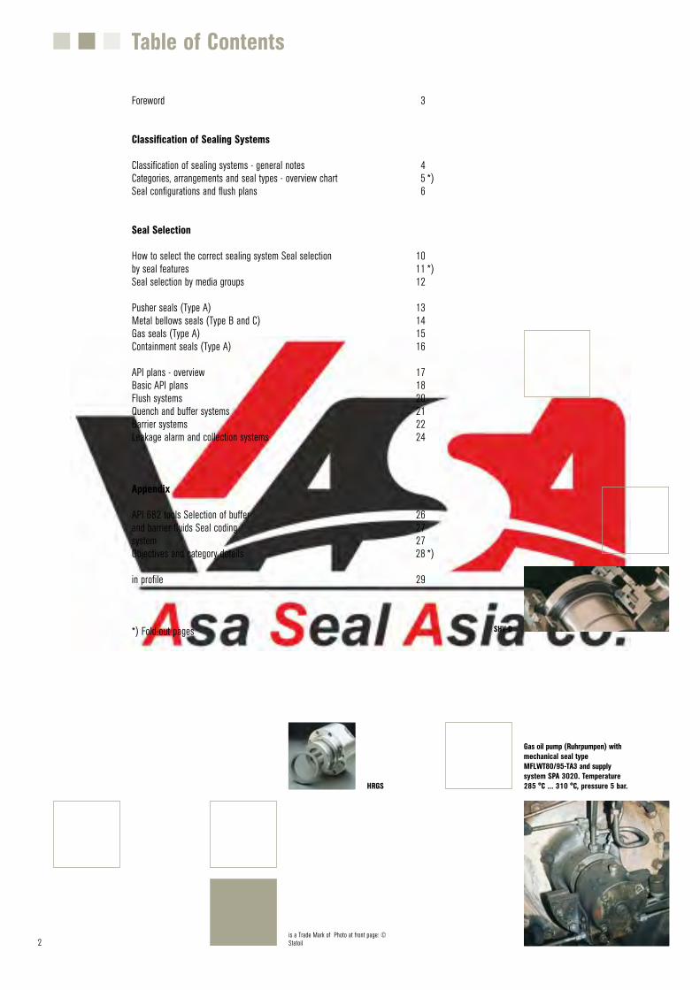
Gas oil pump (Ruhrpumpen) with mechanical seal type MFLWT80/95-TA3 and supplysystem SPA 3020. Temperature 285 °C ... 310 °C, pressure 5 bar.HRGS
SHV-D
is a Trade Mark of Photo at front page: © Statoil
3
This brochure provides basic information about ISO 21049 and API 682. It contains a set of checklists and summaries which give a brief overview that will help to select suitable sealing systems. ISO 21049 is an international standard which is based on API 682 (a standard of the American Petroleum Insti-tute). The content of these two standards is generally identical.
Both standards specify requirements and recommendations for the selection and operation of shaft sealing systems in new or retrofitted centrifugal and rotary pumps. They refer to pumps which are mainly used for hazardous, flammable and/or toxic applications in the petroleum, natural gas and chemical industries.
The improvement of equipment reliability and the reduction of emissions and life-cycle costs are the major targets of these standards.
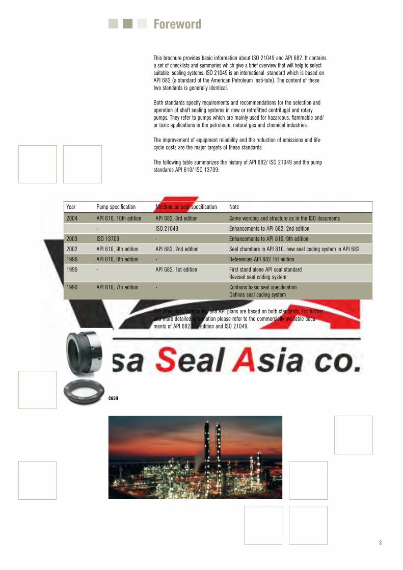
The following table summarizes the history of API 682/ ISO 21049 and the pump standards API 610/ ISO 13709:
The API 682 task force of the American Petroleum Institute is the author of API 682. ISO 21049 has been created by the technical committees ISO/TC 115, SC3 and ISO/TC 67, SC6.
The checklists, summaries and API plans are based on both standards. For further and more detailed information please refer to the commercially available docu-ments of API 682 3rd edition and ISO 21049.
Year Pump specification Mechanical seal specification Note
2004 API 610, 10th edition API 682, 3rd edition Same wording and structure as in the ISO documents- ISO 21049 Enhancements to API 682, 2nd edition
2003 ISO 13709 - Enhancements to API 610, 9th edition2002 API 610, 9th edition API 682, 2nd edition Seal chambers in API 610, new seal coding system in API 6821996 API 610, 8th edition - References API 682 1st edition1995 - API 682, 1st edition First stand alone API seal standard
Revised seal coding system1990 API 610, 7th edition - Contains basic seal specification
Defines seal coding system
Foreword
CGSH
3 4
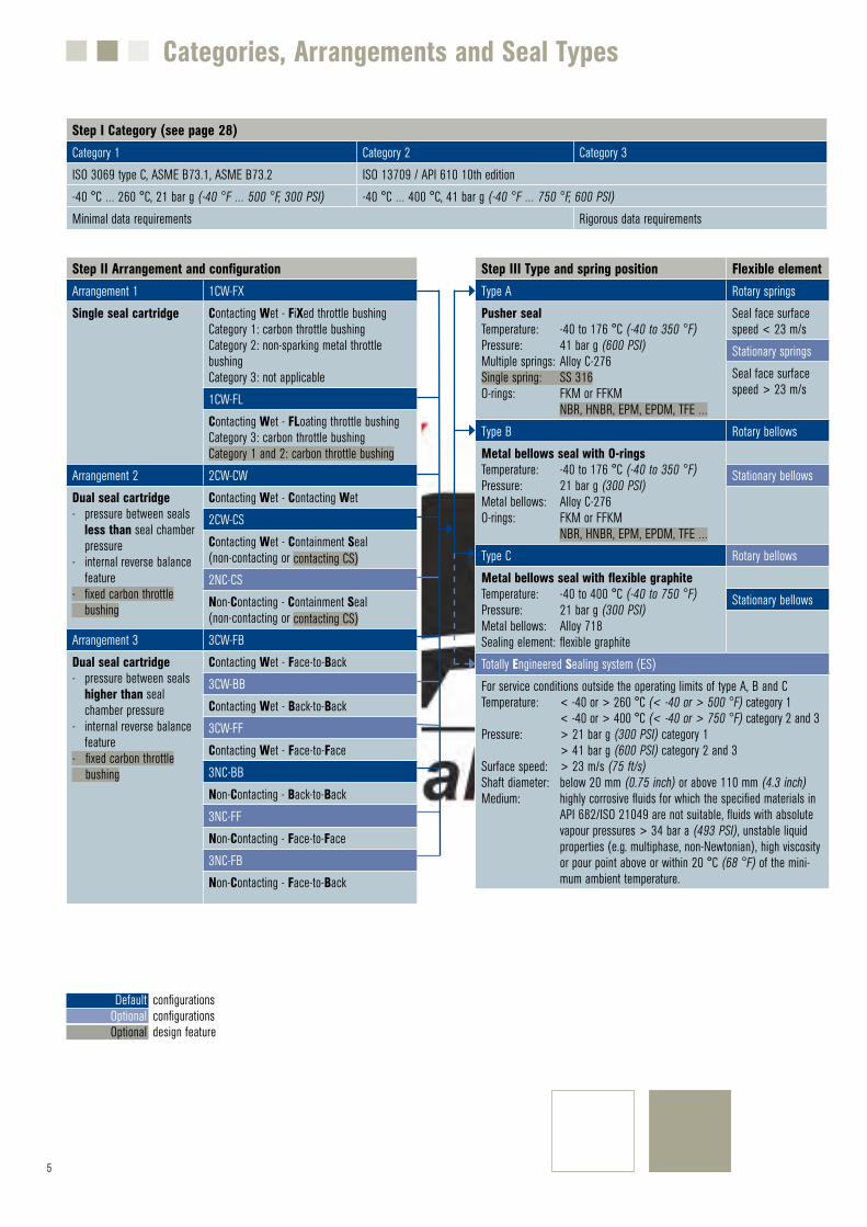
API 682 and ISO 21049 specify a range of different sealing systems. Parame-ters such as category, arrangement, configuration, type and API plans are to be considered.
The chart overleaf is a quick overview about the basic features of the different categories, arrangements and seal types. It also shows the links between these parameters and marks default and optional selections.
Step I: The category determines the applicable seal chamber, basic seal design features, maximum operating conditions, testing and data requirements. Each category has special demands regarding the seal arrangement, configuration and type. There are three different categories.
Step II: Determines the arrangement of the mechanical seal cartridges and their possible configurations.
The configuration determines the sealing method, orientation of the mechanical seal components, the use of containment seals and the required API plans. API 682 and ISO 21049 specify six default configurations and five optional configurations. Each of these configurations can be realized with different seal types.
Step Ill: Definition of the seal type, the design and material of the spring element and the secondary seals.It defines the appropriate operating limits. API 682 and ISO 21049 specify three basic seal types, a fourth option is a totally engineered sealing system (ES).
Step IV: Completes the sealing system classification by selecting the required API plan.
API 682 and ISO 21049 introduce a seal code which contains information about the category, arrangement, type and API plan. For further details please refer to page 27.
Classification of Sealing Systems
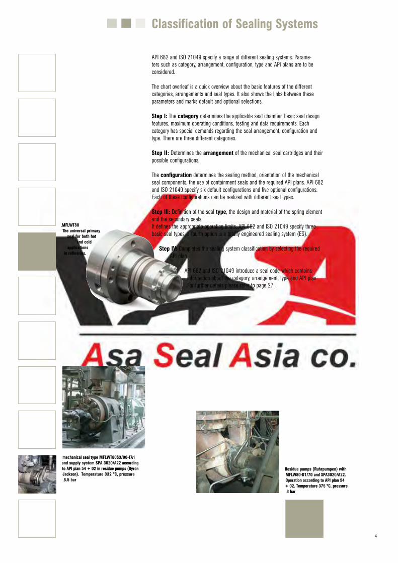
mechanical seal type MFLWT80S3/90-TA1 and supply system SPA 3020/A22 according to API plan 54 + 02 in residue pumps (Byron Jackson). Temperature 332 °C, pressure.8.5 bar
Residue pumps (Ruhrpumpen) with MFLW80-D1/70 and SPA3020/A22. Operation according to API plan 54 + 02. Temperature 375 °C, pressure .3 bar
.MFLWT80 The universal primary
seal for both hot and cold
applications in refineries.
5 6
Default Optional Optional
Categories, Arrangements and Seal Types
configurationsconfigurationsdesign feature
Step I Category (see page 28)Category 1 Category 2 Category 3ISO 3069 type C, ASME B73.1, ASME B73.2 ISO 13709 / API 610 10th edition-40 °C … 260 °C, 21 bar g (-40 °F … 500 °F, 300 PSI) -40 °C … 400 °C, 41 bar g (-40 °F … 750 °F, 600 PSI)Minimal data requirements Rigorous data requirements
Step II Arrangement and configurationArrangement 1 1CW-FXSingle seal cartridge Contacting Wet - FiXed throttle bushing
Category 1: carbon throttle bushingCategory 2: non-sparking metal throttle bushingCategory 3: not applicable1CW-FLContacting Wet - FLoating throttle bushingCategory 3: carbon throttle bushingCategory 1 and 2: carbon throttle bushing
Arrangement 2 2CW-CWDual seal cartridge- pressure between seals
less than seal chamber pressure
- internal reverse balance feature
- fixed carbon throttlebushing
Contacting Wet - Contacting Wet2CW-CSContacting Wet - Containment Seal (non-contacting or contacting CS)2NC-CSNon-Contacting - Containment Seal (non-contacting or contacting CS)
Arrangement 3 3CW-FBDual seal cartridge- pressure between seals
higher than seal chamber pressure
- internal reverse balance feature
- fixed carbon throttlebushing
Contacting Wet - Face-to-Back3CW-BBContacting Wet - Back-to-Back3CW-FFContacting Wet - Face-to-Face3NC-BBNon-Contacting - Back-to-Back3NC-FFNon-Contacting - Face-to-Face3NC-FBNon-Contacting - Face-to-Back
Step III Type and spring position Flexible elementType A Rotary springsPusher sealTemperature: -40 to 176 °C (-40 to 350 °F)Pressure: 41 bar g (600 PSI)Multiple springs: Alloy C-276Single spring: SS 316O-rings: FKM or FFKM
NBR, HNBR, EPM, EPDM, TFE …
Seal face surface speed < 23 m/s Stationary springsSeal face surface speed > 23 m/s
Type B Rotary bellowsMetal bellows seal with O-ringsTemperature: -40 to 176 °C (-40 to 350 °F)Pressure: 21 bar g (300 PSI)Metal bellows: Alloy C-276O-rings: FKM or FFKM
NBR, HNBR, EPM, EPDM, TFE …
Stationary bellows
Type C Rotary bellowsMetal bellows seal with flexible graphiteTemperature: -40 to 400 °C (-40 to 750 °F)Pressure: 21 bar g (300 PSI)Metal bellows: Alloy 718Sealing element: flexible graphite
Stationary bellows
Totally Engineered Sealing system (ES)For service conditions outside the operating limits of type A, B and CTemperature: < -40 or > 260 °C (< -40 or > 500 °F) category 1
< -40 or > 400 °C (< -40 or > 750 °F) category 2 and 3Pressure: > 21 bar g (300 PSI) category 1
> 41 bar g (600 PSI) category 2 and 3Surface speed: > 23 m/s (75 ft/s)Shaft diameter: below 20 mm (0.75 inch) or above 110 mm (4.3 inch) Medium: highly corrosive fluids for which the specified materials in
API 682/ISO 21049 are not suitable, fluids with absolute vapour pressures > 34 bar a (493 PSI), unstable liquid properties (e.g. multiphase, non-Newtonian), high viscosity or pour point above or within 20 °C (68 °F) of the mini-mum ambient temperature.
6
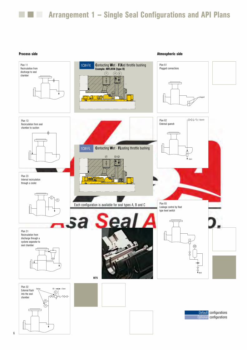
Arrangement 1 – Single Seal Configurations and API Plans
Werb-Nr. 2841
1cw-fx MFL85N
QDF
1CW-FX Contacting Wet - FiXed throttle bushingExample: MFL85N (type B)
Plan 13Recirculation from seal chamber to suction
TI
FI
PI
Option EB ClientPlan 32External flush into the seal chamber
Plan 11Recirculation from discharge to seal chamber
plugged
Plan 61Plugged connections
Werb-Nr. 2787
1cw-fl H75VN
F D Q
1CW-FL Contacting Wet - FLoating throttle bushing
drain
QuenchPlan 62External quench
LSH
drain
Plan 65Leakage control by float type level switch
Process side Atmospheric side
TI
Plan 23Internal recirculation through a cooler
Plan 31Recirculation from discharge through a cyclone separator to seal chamber
H75
Default Optional
configurationsconfigurations
Each configuration is available for seal types A, B and C
7
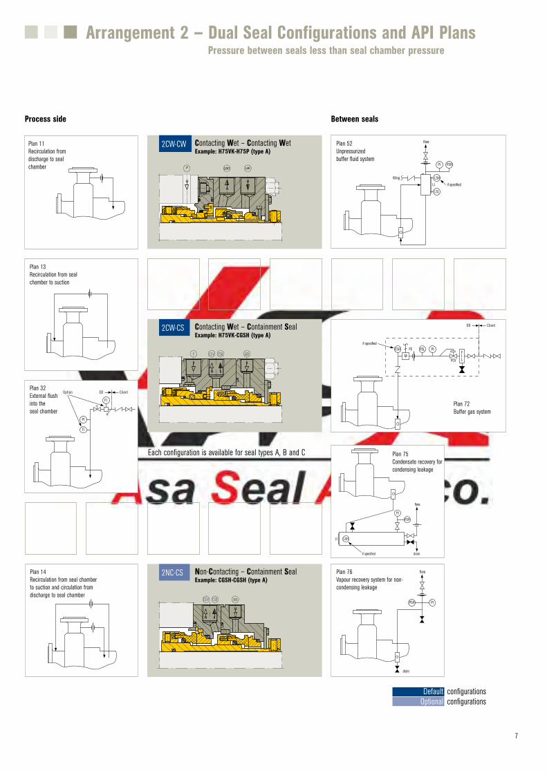
Arrangement 2 – Dual Seal Configurations and API Plans
LBO LBIF
Werb-Nr. 2790
2cw-cw H75VK-PTA
2CW-CW Contacting Wet – Contacting WetExample: H75VK-H75P (type A)
PI PSH
LSH
LSL
if specified
filling
flare
LI
Plan 52Unpressurized buffer fluid system
Werb-Nr. 2789
2cw-cs H75VK+CGSH
2CW-CS Contacting Wet – Containment SealExample: H75VK-CGSH (type A)
Werb-Nr. 2791
2nc-cs CGSH-CGSH
2NC-CS Non-Contacting – Containment SealExample: CGSH-CGSH (type A)
PI
M
PSLFSHFIL
if specified
EB Client
FE
PCV
Plan 72Buffer gas system
PI
LSH
PSH
flare
LI
drainif specified
Plan 75Condensate recovery for condensing leakage
PIPSH
flare
drain
Plan 76Vapour recovery system for non-condensing leakage
Process side Between seals
Pressure between seals less than seal chamber pressure
Plan 13Recirculation from seal chamber to suction
TI
FI
PI
Option EB ClientPlan 32External flush into the seal chamber
Plan 11Recirculation from discharge to seal chamber
Plan 14Recirculation from seal chamber to suction and circulation from discharge to seal chamber
Default Optional
configurationsconfigurations
Each configuration is available for seal types A, B and C
8
Werb-Nr. 2793
3cw-fb H75VK-PTA
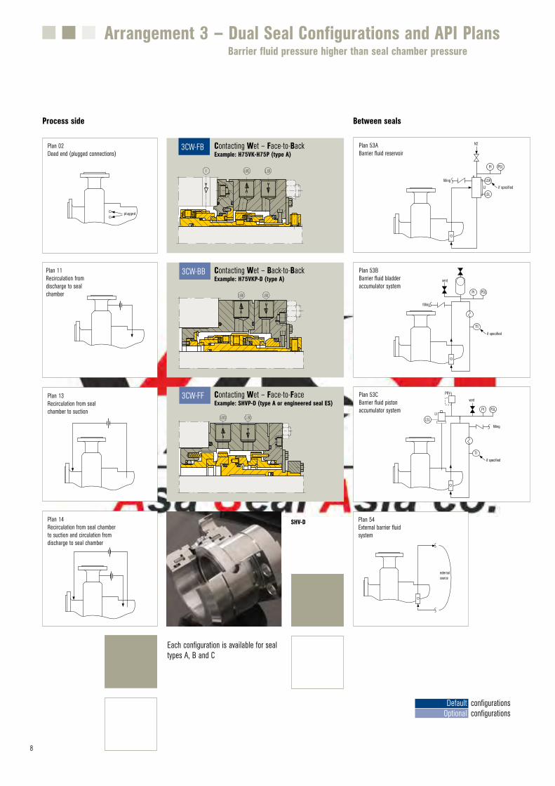
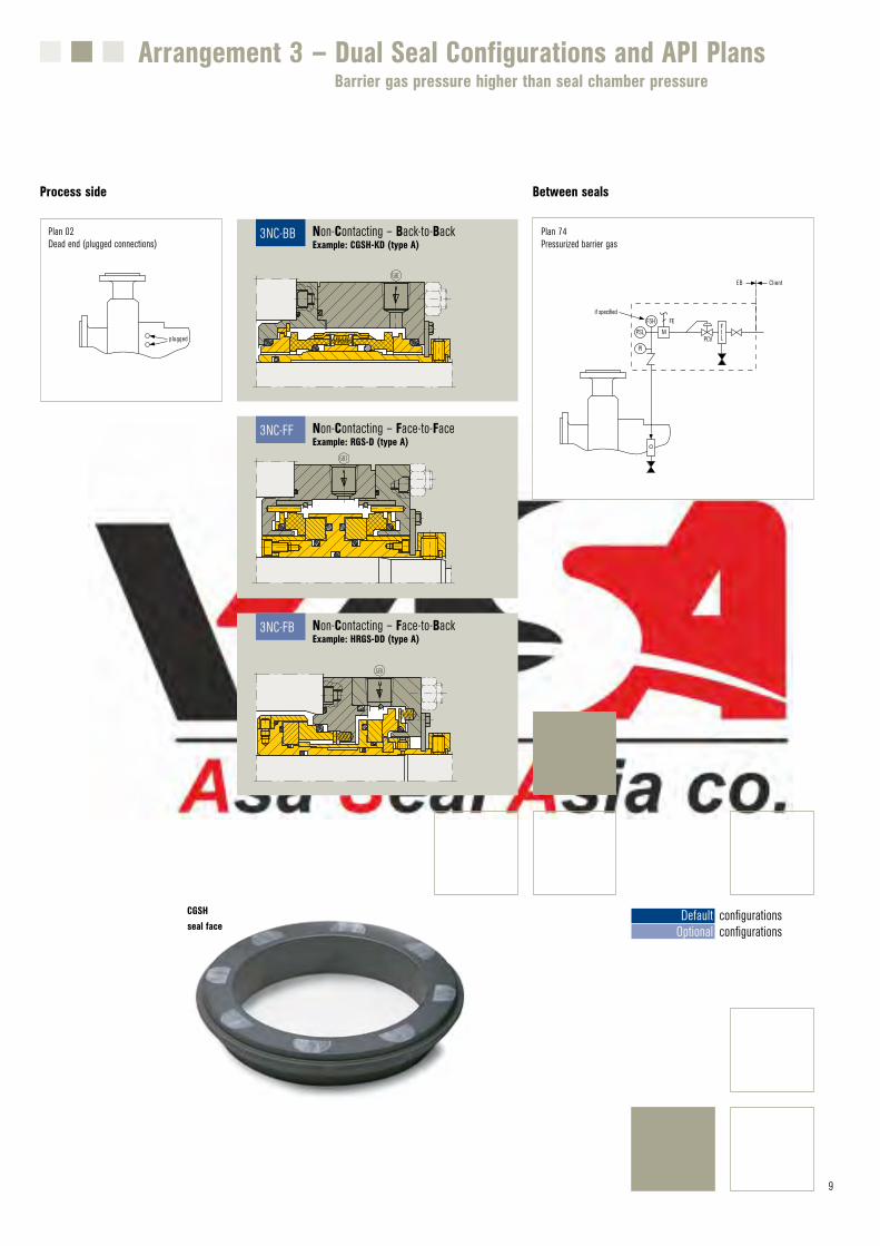
3CW-FB Contacting Wet – Face-to-BackExample: H75VK-H75P (type A)
Werb-Nr. 2792
3cw-bb H75VKP-D
3CW-BB Contacting Wet – Back-to-BackExample: H75VKP-D (type A)
Werb-Nr. 2794
3cw-ff SH
3CW-FF Contacting Wet – Face-to-FaceExample: SHVP-D (type A or engineered seal ES)
Arrangement 3 – Dual Seal Configurations and API Plans
Plan 02Dead end (plugged connections)
PI PSL
LSH
LSL
if specified
filling
N2
LI
Plan 53ABarrier fluid reservoir
Plan 54External barrier fluid system
Process side Between seals
PI
TI
PSL
if specified
filling
vent
Plan 53BBarrier fluid bladder accumulator system
Plan 53CBarrier fluid piston accumulator system
Barrier fluid pressure higher than seal chamber pressure
Plan 13Recirculation from seal chamber to suction
Plan 14Recirculation from seal chamber to suction and circulation from discharge to seal chamber
Plan 11Recirculation from discharge to seal chamber
SHV-D
Default Optional
configurationsconfigurations
Each configuration is available for seal types A, B and C
9
Arrangement 3 – Dual Seal Configurations and API Plans
Werb-Nr. 2796
3nc-fb HRGS-DD
3NC-FB Non-Contacting – Face-to-BackExample: HRGS-DD (type A)
PI
MPSL
FSHFIL
if specified
EB Client
FE
PCV
Plan 74Pressurized barrier gas
Process side Between seals
Werb-Nr. 2795
3nc-bb CGSH-KD
3NC-BB Non-Contacting – Back-to-BackExample: CGSH-KD (type A)
Werb-Nr. 2797
3nc-ff RGS-D
3NC-FF Non-Contacting – Face-to-FaceExample: RGS-D (type A)
Barrier gas pressure higher than seal chamber pressure
Plan 02Dead end (plugged connections)
CGSH seal face
Default Optional
configurationsconfigurations
9 10
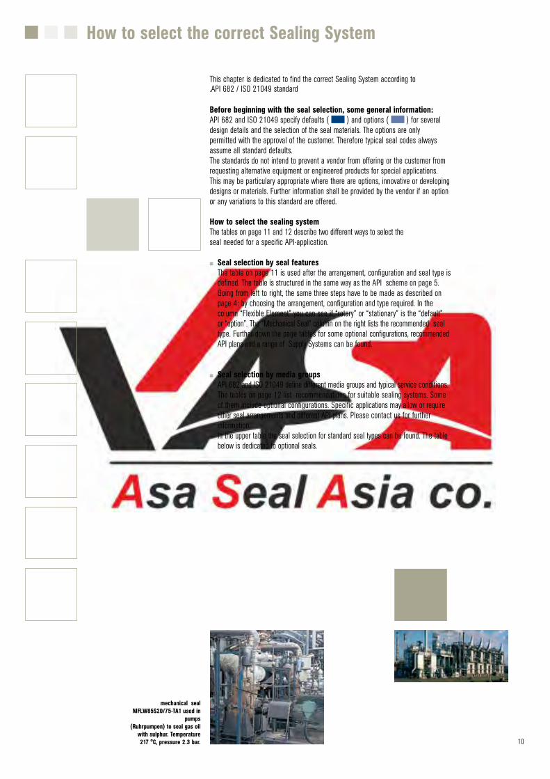
This chapter is dedicated to find the correct Sealing System according to.API 682 / ISO 21049 standard
Before beginning with the seal selection, some general information:API 682 and ISO 21049 specify defaults ( ) and options ( ) for several design details and the selection of the seal materials. The options are only permitted with the approval of the customer. Therefore typical seal codes always assume all standard defaults.The standards do not intend to prevent a vendor from offering or the customer from requesting alternative equipment or engineered products for special applications. This may be particulary appropriate where there are options, innovative or developing designs or materials. Further information shall be provided by the vendor if an option or any variations to this standard are offered.
How to select the sealing systemThe tables on page 11 and 12 describe two different ways to select the seal needed for a specific API-application.
■■ Seal selection by seal features The table on page 11 is used after the arrangement, configuration and seal type is defined. The table is structured in the same way as the API scheme on page 5. Going from left to right, the same three steps have to be made as described on page 4: by choosing the arrangement, configuration and type required. In the column “Flexible Element” you can see if “rotary” or “stationary” is the “default” or “option”. The “Mechanical Seal” column on the right lists the recommended seal type. Further down the page tables for some optional configurations, recommended API plans and a range of Supply Systems can be found.
■■ Seal selection by media groups API 682 and ISO 21049 define different media groups and typical service conditions. The tables on page 12 list recommendations for suitable sealing systems. Some of them include optional configurations. Specific applications may allow or require other seal arrangements and different API plans. Please contact us for further information. In the upper table the seal selection for standard seal types can be found. The table below is dedicated to optional seals.
How to select the correct Sealing System
mechanical seal MFLW85S20/75-TA1 used in
pumps(Ruhrpumpen) to seal gas oil
with sulphur. Temperature 217 °C, pressure 2.3 bar.
11 12
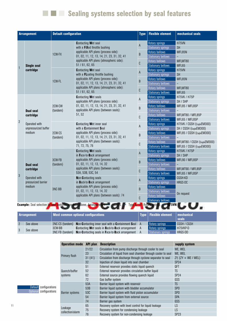
Sealing systems selection by seal features
Arrangement Default configuration Type Flexible element mechanical seals
1 Single sealcartridge
1CW-FX
Contacting Wet sealwith a FiXed throttle bushingapplicable API plans (process side):01, 02, 11, 12, 13, 14, 21, 23, 31, 32, 41applicable API plans (atmospheric side):51 / 61, 62, 65
A Rotary springs H75VNStationary springs SH
B Rotary bellows MFL85NStationary bellows –
C Rotary bellows MFLWT80Stationary bellows MFL65
1CW-FL
Contacting Wet sealwith a FLoating throttle bushingapplicable API plans (process side):01, 02, 11, 12, 13, 14, 21, 23, 31, 32, 41applicable API plans (atmospheric side):51 / 61, 62, 65
A Rotary springs H75VNStationary springs SH
B Rotary bellows MFL85NStationary bellows –
C Rotary bellows MFLWT80Stationary bellows MFL65
2
Dual seal cartridge
Operated with unpressurized buffer medium
2CW-CW(tandem)
Contacting Wet sealsapplicable API plans (process side):01, 02, 11, 12, 13, 14, 21, 23, 31, 32, 41applicable API plans (between seals):51, 52
A Rotary springs H75VK / H75PStationary springs SH / SHP
B Rotary bellows MFL85 / MFL85PStationary bellows –
C Rotary bellows MFLWT80 / MFL85PStationary bellows MFL65 / MFL85P
2CW-CS(tandem)
Contacting Wet inner sealwith a Containment Sealapplicable API plans (process side):01, 02, 11, 12, 13, 14, 21, 23, 31, 32, 41applicable API plans (between seals):71, 72, 75, 76
A Rotary springs H75VK / CGSH (EagleEM300)Stationary springs SH / CGSH (EagleEM300)
B Rotary bellows MFL85 / CGSH (EagleEM300)Stationary bellows –
C Rotary bellows MFLWT80 / CGSH (EagleEM300)Stationary bellows MFL65 / CGSH (EagleEM300)
3
Dual seal cartridge
Operated with pressurized barrier medium
3CW-FB(tandem)
Contacting Wet sealsin Face-to-Back arrangementapplicable API plans (process side):01, 02, 11, 12, 13, 14, 32applicable API plans (between seals):53A, 53B, 53C, 54
A Rotary springs H75VK / H75PStationary springs SH / SHP
B Rotary bellows MFL90 / MFL85PStationary bellows –
C Rotary bellows MFLWT90 / MFL85PStationary bellows MFL65 / MFL85P
3NC-BB
Non-Contacting sealsin Back-to-Back arrangementapplicable API plans (process side):01, 02, 11, 12, 13, 14, 32applicable API plans (between seals): 74
A Rotary springs CGSH-KDStationary springs HRGS-DC
B Rotary bellows
On requestStationary bellows
C Rotary bellowsStationary bellows
Example: Seal selection by seal features: see table above, Arrangement 1 4 1CW-FL 4 Type A 4 Rotary springs 4 H75VN
Arrangement Most common optional configurations Type Flexible element mechanical seals
2 See above 2NC-CS (tandem) Non-Contacting inner seal with a Containment Seal A Rotary springs CGSH / CGSH
3 See above 3CW-BB Contacting Wet seals in Back-to-Back arrangement A Rotary springs H75VKP-D3NC-FB (tandem) Non-Contacting seals in Face-to-Back arrangement A Stationary springs HRGS-DD
Operation mode API plan Description supply system
Primary flush
21/22 Circulation from pump discharge through cooler to seal WE, WEL23 Circulation of liquid from seal chamber through cooler to seal WE, WEL 31 (41) Circulation from discharge through cyclone separator to seal ZY, (ZY + WE / WEL)32 Injection of clean liquid into seal chamber SP24
Quench/buffer systems
51 External reservoir provides static liquid quench QFT52 External reservoir provides circulation buffer liquid TS62 External source provides flowing quench liquid SP2472 Gas buffer system GSS
Barrier systems
53A Barrier liquid system with reservoir TS53B Barrier liquid system with bladder accumulator SPO53C Barrier liquid system with fluid piston accumulator SPO54 Barrier liquid system from external source SPA74 Barrier gas system GSS
Leakage collection/alarm
65 Recovery system with level control for liquid leakage LS75 Recovery system for condensing leakage LS76 Recovery system for non-condensing leakage SP23
Default Optional
configurationsconfigurations
12
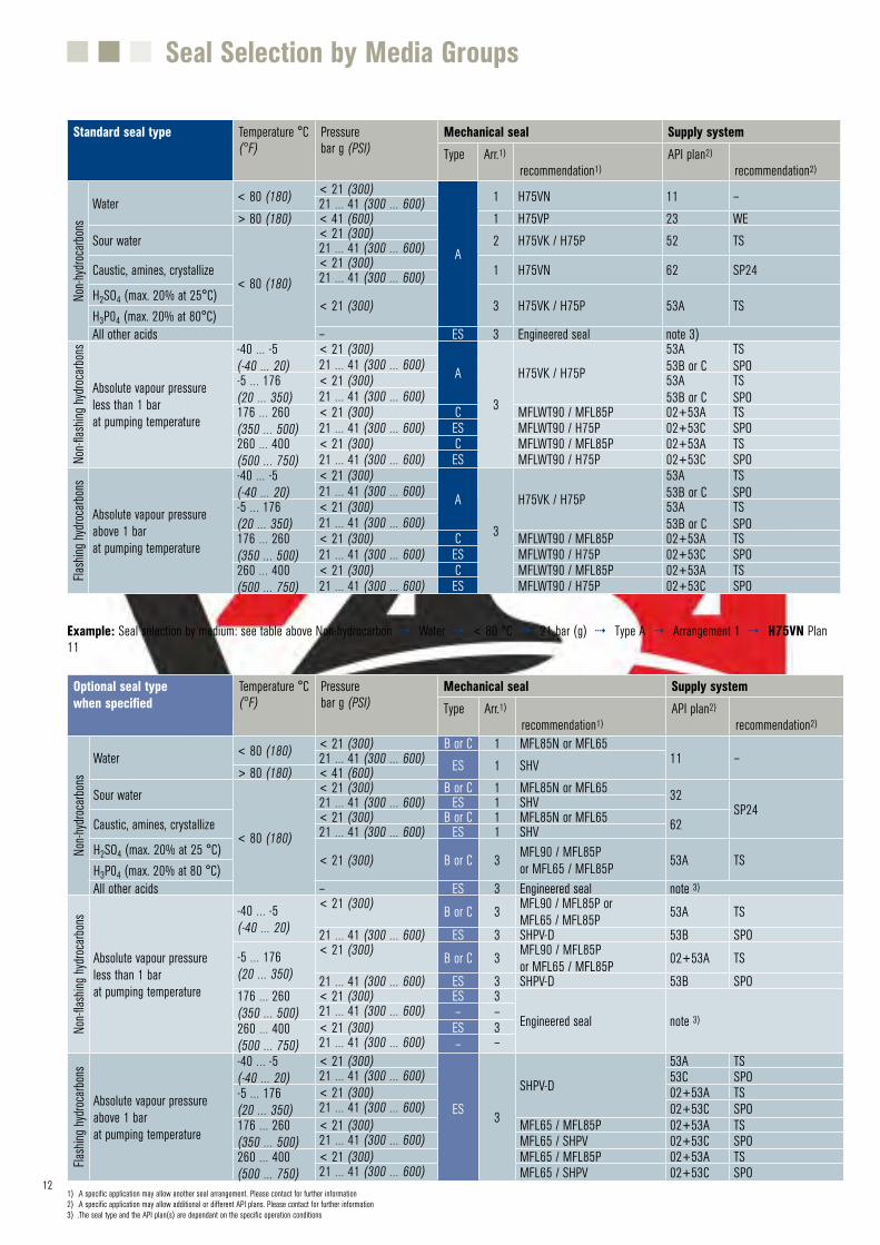
Seal Selection by Media Groups
Standard seal type Temperature °C (°F)
Pressure bar g (PSI)
Mechanical seal Supply systemType Arr.1)
recommendation1)API plan2)
recommendation2)
Non-h
ydroc
arbon
s
Water < 80 (180) < 21 (300)
A
1 H75VN 11 –21 … 41 (300 … 600)> 80 (180) < 41 (600) 1 H75VP 23 WE
Sour water
< 80 (180)
< 21 (300) 2 H75VK / H75P 52 TS21 … 41 (300 … 600)Caustic, amines, crystallize < 21 (300) 1 H75VN 62 SP2421 … 41 (300 … 600)H2SO4 (max. 20% at 25°C)
< 21 (300) 3 H75VK / H75P 53A TSH3P04 (max. 20% at 80°C)All other acids – ES 3 Engineered seal note 3)
Non-fl
ashin
g hyd
rocarb
ons
Absolute vapour pressureless than 1 barat pumping temperature
-40 … -5(-40 … 20)
< 21 (300)
A
3
H75VK / H75P
53A53B or C
TSSPO21 … 41 (300 … 600)
-5 … 176(20 … 350)
< 21 (300) 53A53B or C
TSSPO21 … 41 (300 … 600)
176 … 260(350 … 500)
< 21 (300) C MFLWT90 / MFL85P 02+53A TS21 … 41 (300 … 600) ES MFLWT90 / H75P 02+53C SPO
260 … 400(500 … 750)
< 21 (300) C MFLWT90 / MFL85P 02+53A TS21 … 41 (300 … 600) ES MFLWT90 / H75P 02+53C SPO
Flash
ing hy
droca
rbons
Absolute vapour pressureabove 1 barat pumping temperature
-40 … -5(-40 … 20)
< 21 (300)
A
3
H75VK / H75P
53A53B or C
TSSPO21 … 41 (300 … 600)
-5 … 176(20 … 350)
< 21 (300) 53A53B or C
TSSPO21 … 41 (300 … 600)
176 … 260(350 … 500)
< 21 (300) C MFLWT90 / MFL85P 02+53A TS21 … 41 (300 … 600) ES MFLWT90 / H75P 02+53C SPO
260 … 400(500 … 750)
< 21 (300) C MFLWT90 / MFL85P 02+53A TS21 … 41 (300 … 600) ES MFLWT90 / H75P 02+53C SPO
Example: Seal selection by medium: see table above Non-hydrocarbon 4 Water 4 < 80 °C 4 21 bar (g) 4 Type A 4 Arrangement 1 4 H75VN Plan 11
Optional seal typewhen specified
Temperature °C (°F)
Pressure bar g (PSI)
Mechanical seal Supply systemType Arr.1)
recommendation1)API plan2)
recommendation2)
Non-h
ydroc
arbon
s
Water < 80 (180) < 21 (300) B or C 1 MFL85N or MFL6511 –21 … 41 (300 … 600) ES 1 SHV> 80 (180) < 41 (600)
Sour water
< 80 (180)
< 21 (300) B or C 1 MFL85N or MFL65 32SP2421 … 41 (300 … 600) ES 1 SHV
Caustic, amines, crystallize < 21 (300) B or C 1 MFL85N or MFL65 6221 … 41 (300 … 600) ES 1 SHVH2SO4 (max. 20% at 25 °C)
< 21 (300) B or C 3 MFL90 / MFL85Por MFL65 / MFL85P 53A TS
H3P04 (max. 20% at 80 °C)All other acids – ES 3 Engineered seal note 3)
Non-fl
ashin
g hyd
rocarb
ons
Absolute vapour pressureless than 1 barat pumping temperature
-40 … -5(-40 … 20)
< 21 (300) B or C 3 MFL90 / MFL85P or MFL65 / MFL85P 53A TS
21 … 41 (300 … 600) ES 3 SHPV-D 53B SPO-5 … 176(20 … 350)
< 21 (300) B or C 3 MFL90 / MFL85Por MFL65 / MFL85P 02+53A TS
21 … 41 (300 … 600) ES 3 SHPV-D 53B SPO176 … 260(350 … 500)
< 21 (300) ES 3
Engineered seal note 3)21 … 41 (300 … 600) – –
260 … 400(500 … 750)
< 21 (300) ES 321 … 41 (300 … 600) – –
Flash
ing hy
droca
rbons
Absolute vapour pressureabove 1 barat pumping temperature
-40 … -5(-40 … 20)
< 21 (300)
ES 3
SHPV-D
53A TS21 … 41 (300 … 600) 53C SPO
-5 … 176(20 … 350)
< 21 (300) 02+53A TS21 … 41 (300 … 600) 02+53C SPO
176 … 260(350 … 500)
< 21 (300) MFL65 / MFL85P 02+53A TS21 … 41 (300 … 600) MFL65 / SHPV 02+53C SPO
260 … 400(500 … 750)
< 21 (300) MFL65 / MFL85P 02+53A TS21 … 41 (300 … 600) MFL65 / SHPV 02+53C SPO
1) .A specific application may allow another seal arrangement. Please contact for further information2) .A specific application may allow additional or different API plans. Please contact for further information3) .The seal type and the API plan(s) are dependant on the specific operation conditions
13
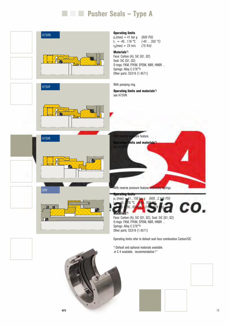
Pusher Seals – Type A
Operating limitsp1(max) = 41 bar g (600 PSI)t1 = -40…176 °C (-40 … 350 °F)vg(max) = 23 m/s (75 ft/s)
Materials*)
Face: Carbon (A), SiC (Q1, Q2)Seat: SiC (Q1, Q2)O-rings: FKM, FFKM, EPDM, NBR, HNBR …Springs: Alloy C-276**)
Other parts: SS316 (1.4571)
Werb-Nr. 2801
H75VN
H75VN
Werb-Nr. 2802
H75VP
H75VP
Werb-Nr. 2800
H75VK
H75VK
Werb-Nr. 2809
SH
SHV
With pumping ring.
Operating limits and materials*)
see H75VN
With reverse pressure feature.
Operating limits and materials*)
see H75VN
With reverse pressure feature, stationary springs.
Operating limitsp1 (max) = 41…150 bar g (600…2,115 PSI)t1 = -40…176 °C (-40…350 °F)vg(max) = 50…60 m/s (164…229 ft/s)
Materials*)
Face: Carbon (A), SiC (Q1, Q2), Seat: SiC (Q1, Q2)O-rings: FKM, FFKM, EPDM, NBR, HNBR …Springs: Alloy C-276**)
Other parts: SS316 (1.4571)
Operating limits refer to default seal face combination Carbon/SIC
*) Default and optional materials available..in C-4 available, recommendation (**
H75
14 MFL 85
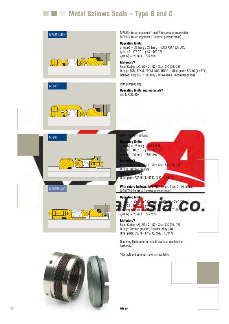
Metal Bellows Seals – Type B and C
MFL85N for arrangement 1 and 2 (external pressurization)MFL90N for arrangement 3 (internal pressurization)
Operating limitsp1 (max) = 25 bar g / 23 bar g (363 PSI / 334 PSI)t1 = -40…176 °C (-40…350 °F)vg(max) = 23 m/s (75 ft/s)
Materials*)
Face: Carbon (A), SiC (Q1, Q2), Seat: SiC (Q1, Q2) O-rings: FKM, FFKM, EPDM, NBR, HNBR…, Other parts: SS316 (1.4571) Bellows: Alloy C-276 (in Alloy 718 available, recommendation)
With pumping ring.
Operating limits and materials*)
see MFL85/90N
With stationary bellows.
Operating limitsp1 (max) = 25 bar g (363 PSI)t1 = -40…400 °C (-40…750 °F)vg(max) = 50 m/s (164 ft/s)
Materials*)
Face: Carbon (A), SiC (Q1, Q2), Seat: SiC (Q1, Q2)O-rings: Flexible graphiteBellows: Alloy 718Other parts: SS316 (1.4571), Ni42 (1.3917)
With rotary bellows. MFLWT80 for arr. 1 and 2 (ext. press.), MFLWT90 for arr. 3 (internal pressurization).
Operating limitsp1(max) = 25 bar g / 23 bar g (363 PSI / 334 PSI)t1 = -20…400 °C (-4…750 °F)For temperatures below -20 °C (-4 °F) MFLCT 80/92vg(max) = 23 m/s (75 ft/s)
Materials*)
Face: Carbon (A), SiC (Q1, Q2), Seat: SiC (Q1, Q2)O-rings: Flexible graphite, Bellows: Alloy 718Other parts: SS316 (1.4571), Ni42 (1.3917)
Operating limits refer to default seal face combination Carbon/SIC.
*) Default and optional materials available.
Werb-Nr. 2806
MFL85N
Werb-Nr. 2807
MFL85P
MFL85P
Werb-Nr. 2805
MFL65
MFL65
Werb-Nr. 2808
MFLWT80
MFLWT80/90
MFL85N/90N
15
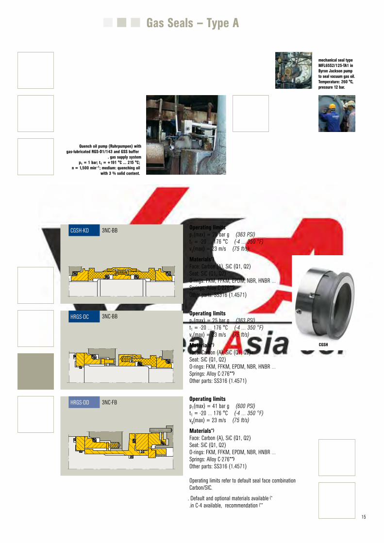
Gas Seals – Type A
Operating limitsp1(max) = 25 bar g (363 PSI)t1 = -20 … 176 °C (-4 … 350 °F)vg(max) = 23 m/s (75 ft/s)
Materials*)
Face: Carbon (A), SiC (Q1, Q2)Seat: SiC (Q1, Q2)O-rings: FKM, FFKM, EPDM, NBR, HNBR …Springs: Alloy C-276**)
Other parts: SS316 (1.4571)
Operating limitsp1(max) = 25 bar g (363 PSI)t1 = -20 … 176 °C (-4 … 350 °F)vg(max) = 23 m/s (75 ft/s)
Materials*)
Face: Carbon (A), SiC (Q1, Q2)Seat: SiC (Q1, Q2)O-rings: FKM, FFKM, EPDM, NBR, HNBR …Springs: Alloy C-276**)
Other parts: SS316 (1.4571)
Operating limitsp1(max) = 41 bar g (600 PSI)t1 = -20 … 176 °C (-4 … 350 °F)vg(max) = 23 m/s (75 ft/s)
Materials*)
Face: Carbon (A), SiC (Q1, Q2)Seat: SiC (Q1, Q2)O-rings: FKM, FFKM, EPDM, NBR, HNBR …Springs: Alloy C-276**)
Other parts: SS316 (1.4571)
Operating limits refer to default seal face combination Carbon/SIC.
. Default and optional materials available (*
.in C-4 available, recommendation (**
Werb-Nr. 2799
CGSH-D
CGSH-KD
Werb-Nr. 2803
HRGS-DC
HRGS-DC
Werb-Nr. 2804
HRGS-DD
HRGS-DD
3NC-BB
3NC-BB
3NC-FB
mechanical seal type MFL65S2/125-TA1 in Byron Jackson pump to seal vacuum gas oil. Temperature: 260 °C, pressure 12 bar.
Quench oil pump (Ruhrpumpen) with gas-lubricated RGS-D1/143 and GSS buffer
. gas supply systemp1 = 1 bar; t1 = +191 °C ... 215 °C;
n = 1,500 min–1; medium: quenching oil with 3 % solid content.
CGSH
16
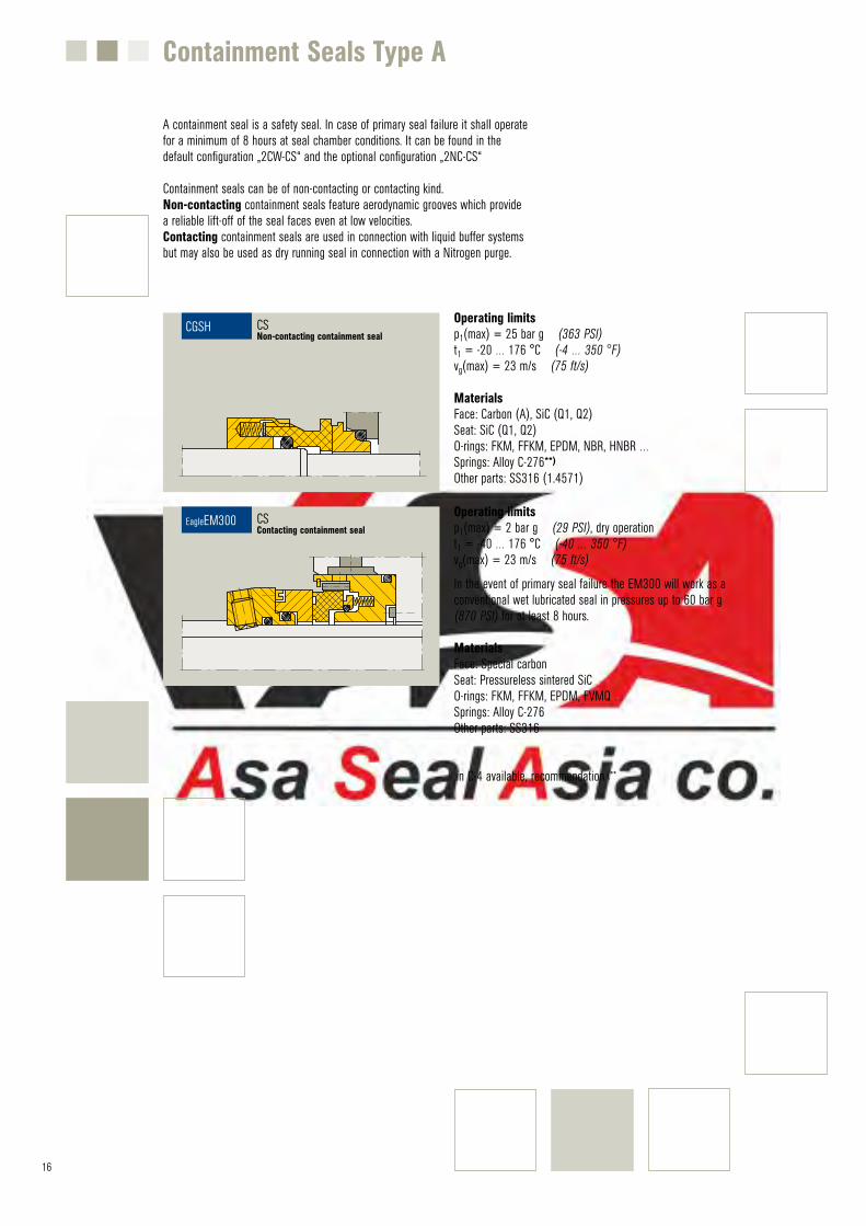
Operating limitsp1(max) = 25 bar g (363 PSI)t1 = -20 … 176 °C (-4 … 350 °F)vg(max) = 23 m/s (75 ft/s)
MaterialsFace: Carbon (A), SiC (Q1, Q2)Seat: SiC (Q1, Q2)O-rings: FKM, FFKM, EPDM, NBR, HNBR …Springs: Alloy C-276**)
Other parts: SS316 (1.4571)
Werb-Nr. 2798
CGSH
CGSH CSNon-contacting containment seal
Containment Seals Type A
A containment seal is a safety seal. In case of primary seal failure it shall operatefor a minimum of 8 hours at seal chamber conditions. It can be found in the default configuration „2CW-CS“ and the optional configuration „2NC-CS“
Containment seals can be of non-contacting or contacting kind. Non-contacting containment seals feature aerodynamic grooves which providea reliable lift-off of the seal faces even at low velocities. Contacting containment seals are used in connection with liquid buffer systems but may also be used as dry running seal in connection with a Nitrogen purge.
Operating limitsp1(max) = 2 bar g (29 PSI), dry operationt1 = -40 … 176 °C (-40 … 350 °F)vg(max) = 23 m/s (75 ft/s)
In the event of primary seal failure the EM300 will work as a conventional wet lubricated seal in pressures up to 60 bar g (870 PSI) for at least 8 hours.
MaterialsFace: Special carbonSeat: Pressureless sintered SiCO-rings: FKM, FFKM, EPDM, FVMQ …Springs: Alloy C-276Other parts: SS316
.in C-4 available, recommendation (**
Werb.Nr. 2827
EM300
EagleEM300 CSContacting containment seal
17
Gas oil charge feed pump sealed with MFL65 and HSHF1 in tandem arrangement. Temperature 280 °C, pressure 3.5 to 15 bar.
An API plan determines the piping or auxiliary system which is connected to the seal chamber or/and the mechanical seal cartridge. Certain seal configurations only work in combination with appropriate API plans. Other API plans can also be applied to improve the performance of a mechanical seal. The combination of external control and supply units which are used to realize a certain API plan is usually called a “Supply System”.
© S
tatoil
MFL 65
API Plans – Overview
18
API Plans – Process Side
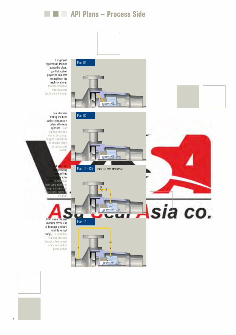
Plan 01For general
applications. Product pumped is clean, good lubrication
properties and heat removal from the mechanical seal.
Internal circulation from the pump
discharge to the seal.
Plan 02Seal chamber
cooling and neck bush are necessary,
unless otherwise specified. Dead
end seal chamber with no circulation.
Plugged connections for possible future
circulation and quench.
Plan 13Used where the seal chamber pressure is
at discharge pressure (mainly vertical
pumps). Recirculation from seal chamber
through a flow control orifice and back to
pump suction
Plan 11 (12)Used when the product being
pumped has occasional particles
only. Recirculation from pump discharge
through a strainer and flow control orifice to
the seal.
Plan 12: With strainer St
St
19
API Plans – Process Side
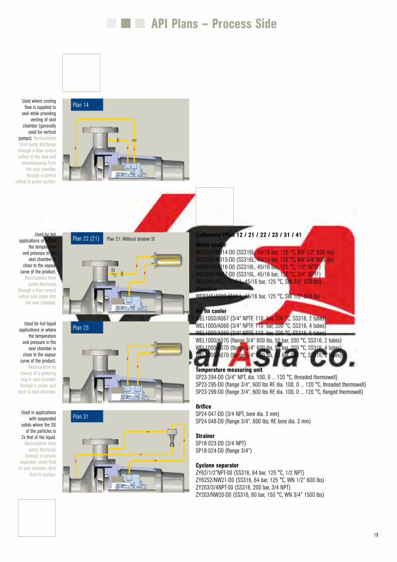
Plan 14Used where cooling
flow is supplied to seal while providing
venting of seal chamber (generally
used for vertical pumps). Recirculation from pump discharge
through a flow control orifice to the seal and
simultaneously from the seal chamber through a control
orifice to pump suction.
(reference (Plan 12 / 21 / 22 / 23 / 31 / 41 Water coolerWE6045/M014-D0 (SS316L, 45/16 bar, 125 °C, BW 1/2“ 600 lbs)WE6045/M015-D0 (SS316L, 45/16 bar, 125 °C, BW 3/4“ 600 lbs)WE6045/M016-D0 (SS316L, 45/16 bar, 125 °C, 1/2“ NPTF)WE6045/M017-D0 (SS316L, 45/16 bar, 125 °C, 3/4“ NPTF)WE6045/A001 (316 L, 45/16 bar, 125 °C, SW 3/4“ 600 lbs)alternative WE6045/A002 (316 L, 45/16 bar, 125 °C, SW 1/2“ 600 lbs
Air fin cooler WEL1000/A067 (3/4“ NPTF, 110 bar, 200 °C, SS316, 2 tubes)WEL1000/A068 (3/4“ NPTF, 110 bar, 200 °C, SS316, 4 tubes)WEL1000/A069 (3/4“ NPTF, 110 bar, 200 °C, SS316, 6 tubes)WEL1000/A070 (flange 3/4“ 600 lbs, 50 bar, 200 °C, SS316, 2 tubes)WEL1000/A070 (flange 3/4“ 600 lbs, 50 bar, 200 °C, SS316, 4 tubes)WEL1000/A070 (flange 3/4“ 600 lbs, 50 bar, 200 °C, SS316, 6 tubes)
Temperature measuring unitSP23-294-D0 (3/4“ NPT, dia. 100, 0 ... 120 °C, threaded thermowell)SP23-295-D0 (flange 3/4“, 600 lbs RF, dia. 100, 0 ... 120 °C, threaded thermowell)SP23-299-D0 (flange 3/4“, 600 lbs RF, dia. 100, 0 ... 120 °C, flanged thermowell)
OrificeSP24-047-D0 (3/4 NPT, bore dia. 3 mm)SP24-048-D0 (flange 3/4“, 600 lbs, RF, bore dia. 3 mm)
StrainerSP18-023-D0 (3/4 NPT)SP18-024-D0 (flange 3/4“)
Cyclone separator ZY62/1/2”NPT-00 (SS316, 64 bar, 125 °C, 1/2 NPT)ZY62S2/NW21-D0 (SS316, 64 bar, 125 °C, WN 1/2” 600 lbs)ZY203/3/4NPT-00 (SS316, 200 bar, 3/4 NPT)ZY203/NW20-D0 (SS316, 80 bar, 150 °C, WN 3/4” 1500 lbs)
Plan 23Used for hot liquid
applications or wherethe temperature
and pressure in theseal chamber is
close to the vapourcurve of the product.
Recirculation bymeans of a pumpingring in seal chamberthrough a cooler and
back to seal chamber.
Plan 31Used in applications
with suspended solids where the SG
of the particles is 2x that of the liquid.
Recirculation from pump discharge
through a cyclone separator, clean fluid
to seal chamber, dirty fluid to suction.
Plan 22 (21)Used for hot
applications or where the temperature
and pressure in the seal chamber is
close to the vapour curve of the product.
Recirculation from pump discharge
through a flow control orifice and cooler into
the seal chamber.
Plan 21: Without strainer St
St
20
API Plans – Process Side
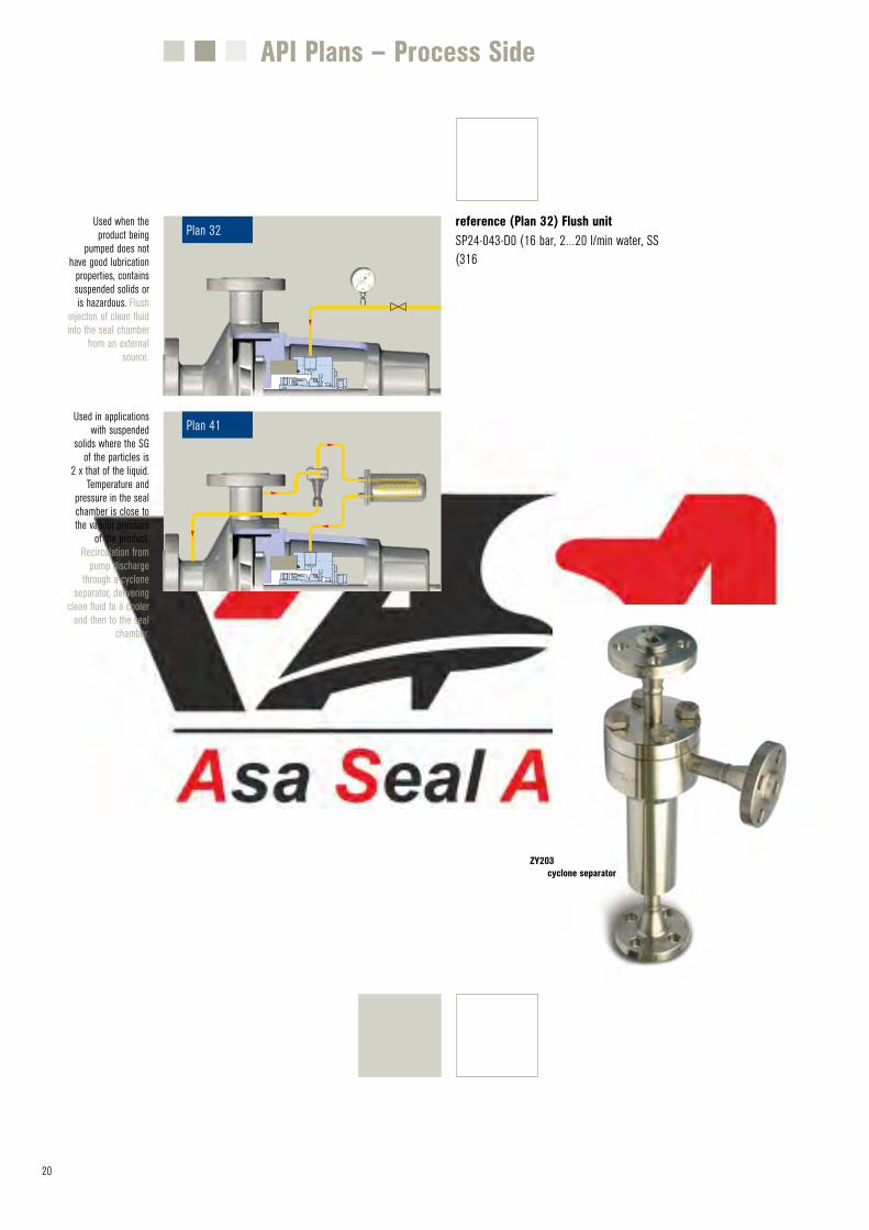
Plan 41 Used in applications
with suspended solids where the SG
of the particles is 2 x that of the liquid.
Temperature and pressure in the seal chamber is close to the vapour pressure
of the product.Recirculation from
pump discharge through a cyclone
separator, delivering clean fluid to a cooler
and then to the seal chamber.
Plan 32 Used when the product being
pumped does not have good lubrication
properties, contains suspended solids or is hazardous. Flush
injecton of clean fluid into the seal chamber
from an external source.
reference (Plan 32) Flush unit SP24-043-D0 (16 bar, 2…20 l/min water, SS(316
ZY203 cyclone separator
21
API Plans – Between seals
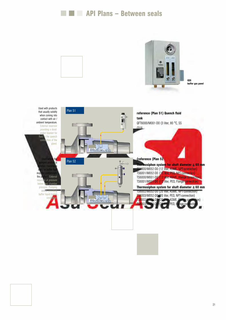
reference (Plan 51) Quench fluid tank QFT6000/M001-DO (3 liter, 80 °C, SS(316
Plan 51Used with products that usually solidify when coming into contact with air /
ambient temperature. External reservoir providing a dead-ended blanket for
fluid to the quench connection of the
gland.
Plan 52Used where the
pumped product is harmful / hazardous and / or buffer fluid
may not contaminate the product. External reservoir at pressure below seal chamber
pressure. Pumping device providing
buffer liquid forced circulation.
(reference (Plan 52 Thermosiphon system for shaft diameter 60 mmTS6000/M052-D0 (12 liter, ASME, NPT-connection)TS6001/M052-D0 (12 liter, PED, NPT-connection)TS6000/M001-D0 (12 liter, ASME, Flange-connection)TS6001/M001-D0 (12 liter, PED, Flange-connection) Thermosiphon system for shaft diameter 60 mmTS6002/M052-D0 (20 liter, ASME, NPT-connection)TS6003/M052-D0 (20 liter, PED, NPT-connection)TS6002/M004-D0 (20 liter, ASME, Flange-connection)TS6003/M003-D0 (20 liter, PED, Flange-connection)
=<
=
<
GSS buffer gas panel
22
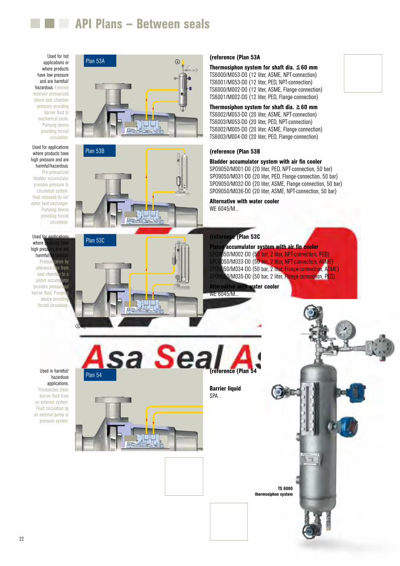
(reference (Plan 53A Thermosiphon system for shaft dia. 60 mmTS6000/M053-D0 (12 liter, ASME, NPT-connection)TS6001/M053-D0 (12 liter, PED, NPT-connection)TS6000/M002-D0 (12 liter, ASME, Flange-connection)TS6001/M002-D0 (12 liter, PED, Flange-connection) Thermosiphon system for shaft dia. 60 mmTS6002/M053-D0 (20 liter, ASME, NPT-connection)TS6003/M053-D0 (20 liter, PED, NPT-connection)TS6002/M005-D0 (20 liter, ASME, Flange-connection)TS6003/M004-D0 (20 liter, PED, Flange-connection)
(reference (Plan 53B Bladder accumulator system with air fin coolerSPO9050/M001-D0 (20 liter, PED, NPT-connection, 50 bar)SPO9050/M031-D0 (20 liter, PED, Flange-connection, 50 bar)SPO9050/M032-D0 (20 liter, ASME, Flange-connection, 50 bar) SPO9050/M036-D0 (20 liter, ASME, NPT-connection, 50 bar)Alternative with water coolerWE 6045/M...
Plan 53BUsed for applications where products have
high pressure and are harmful/hazardous.
Pre-pressurized bladder accumulator provides pressure to
circulation system. Heat removed by air/
water heat exchanger. Pumping device providing forced
circulation.
(reference (Plan 53C Piston accumulator system with air fin coolerSPO9050/M002-D0 (50 bar, 2 liter, NPT-connection, PED)SPO9050/M033-D0 (50 bar, 2 liter, NPT-connection, ASME)SPO9050/M034-D0 (50 bar, 2 liter, Flange-connection, ASME)SPO9050/M035-D0 (50 bar, 2 liter, Flange-connection, PED)Alternative with water coolerWE 6045/M...
=<
=
<
TS 6000
thermosiphon system
Plan 53AUsed for hot
applications or where products
have low pressure and are harmful/
hazardous. External reservoir pressurized above seal chamber
pressure providing barrier fluid to
mechanical seals. Pumpng device
providing forced circulation.
A
Plan 53CUsed for applications where products have
high pressure and are harmful/hazardous.
Pressurization by reference line from seal chamber to a
piston accumulator provides pressurized
barrier fluid. Pumping device providing
forced circulation.
N2A
(reference (Plan 54
Barrier liquid SPA…
Plan 54Used in harmful/
hazardous applications.
Pressurized clean barrier fluid from
an external system. Fluid circulation by
an external pump or pressure system.
API Plans – Between seals
23
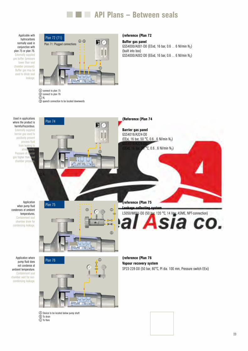
(reference (Plan 75 Leakage collecting systemLS050/M001-D0 (50 bar, 120 °C, 14 liter, ASME, NPT-connection)
(reference (Plan 76 Vapour recovery systemSP23-228-D0 (50 bar, 80°C, Pl dia. 100 mm, Pressure switch EExi)
Plan 75Application
when pump fluid condenses at ambient
temperatures. Containment seal chamber drain for
condensing leakage.
A C
B
Plan 76Application where
pump fluid does not condense at
ambient temperature. Containment seal
chamber vent for non-condensing leakage.
Device to be located below pump shaftTo drainTo flare
C
A
CB
(reference (Plan 72 Buffer gas panel GSS4000/A001-D0 (EExd, 16 bar, 0.6 … 6 Nl/min N2)(built into box) GSS4000/A002-D0 (EExd, 16 bar, 0.6 … 6 Nl/min N2)
(Reference (Plan 74
Barrier gas panel GSS4016/A324-D0 (EExi, 16 bar, 50 °C, 0.6…6 Nl/min N2)GSS4016/A326-D0 (EExd, 16 bar, 50 °C, 0.6…6 Nl/min N2)
Plan 74Used in applications where the product is
harmful/hazardous. Externally supplied barrier gas used to
positively prevent process fluid
from leaking to atmosphere.
Pressure of barrier gas higher than seal
chamber pressure.
N2A
A
API Plans – Between seals
connect to plan 75connect to plan 76N2
quench connection to be located downwards
ABCD
Plan 72 (71)Applicable with
hydrocarbons normally used in conjunction with
plan 75 or plan 76. Externally supplied
gas buffer (pressure lower than seal
chamber pressure). Buffer gas may be used to dilute seal
leakage.
A B
C
Plan 71: Plugged connections
24
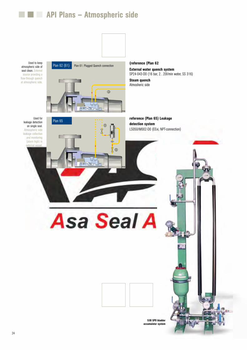
53B SPO bladder accumulator system
API Plans – Atmospheric side
reference (Plan 65) Leakage detection systemLS050/M002-D0 (EExi, NPT-connection)
Used for leakage detection
on single seal. Atmospheric side
leakage collection and monitoring (alarm high) in external vessel.
Plan 65A
B
(reference (Plan 62 External water quench systemSP24-043-D0 (16 bar, 2…20l/min water, SS 316) Steam quenchAtmosheric side
Plan 62 (61)Used to keep
atmospheric side of seal clean. External source providing a
flow-through quench at atmospheric side.
D
Plan 61: Plugged Quench connection
Appendix
25
The following tables give a quick overview about the requirements of the different categories, the selection of suitable buffer or barrier fluids and the seal coding system according to API 682 / ISO 21049 and the seal c ode.
mechanical seal MFLW85S20 in pump
(Thyssen Ruhrpumpen) to seal gas oil with
sulphur. Temperature , 217 °C
.pressure 2.3 bar
26
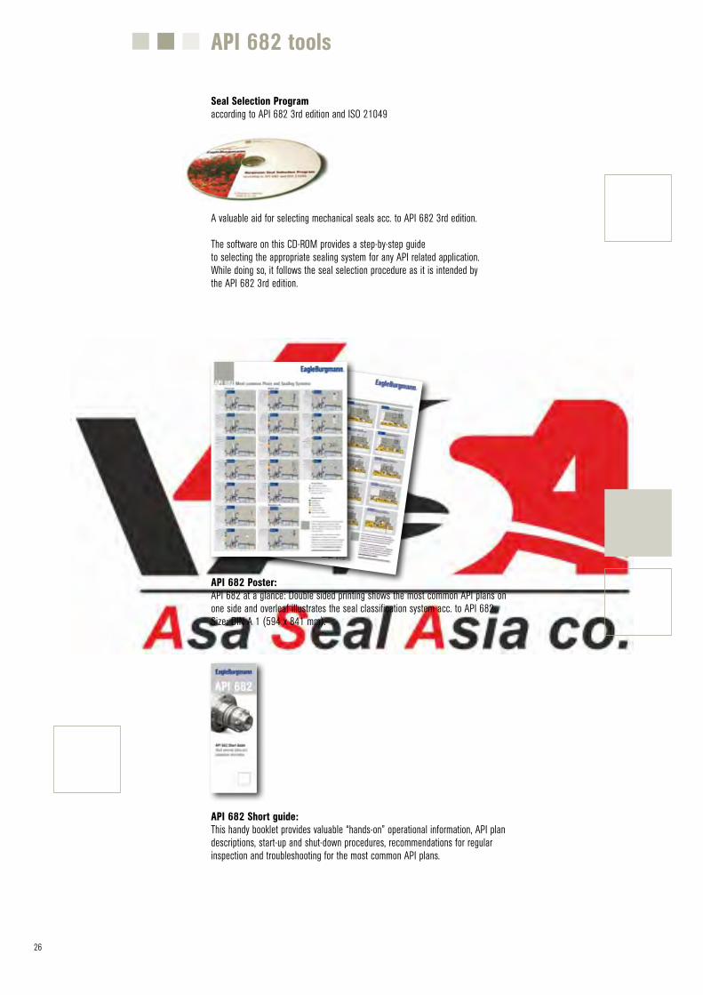
Seal Selection Programaccording to API 682 3rd edition and ISO 21049
API 682 tools
A valuable aid for selecting mechanical seals acc. to API 682 3rd edition.
The software on this CD-ROM provides a step-by-step guide to selecting the appropriate sealing system for any API related application.While doing so, it follows the seal selection procedure as it is intended by the API 682 3rd edition.
API 682 Poster: API 682 at a glance: Double sided printing shows the most common API plans on one side and overleaf illustrates the seal classification system acc. to API 682 Size: DIN A 1 (594 x 841 mm).
API 682 Short guide: This handy booklet provides valuable “hands-on” operational information, API plan descriptions, start-up and shut-down procedures, recommendations for regular inspection and troubleshooting for the most common API plans.
27
Selection of Buffer and Barrier MediumsSeal Coding System
mechanical seal type MFLWT80/S1-FD/58-E3 with thermosiphon system TS2000/M073-A1 to seal ethylene oxide (Sulzer pumps).
Return pump (KSB) with tandem seal type H75S2/60-H75F2/55 according to API 682 Plan 52 for sealing C4 hydrocarbon. Buffer.medium: methanol
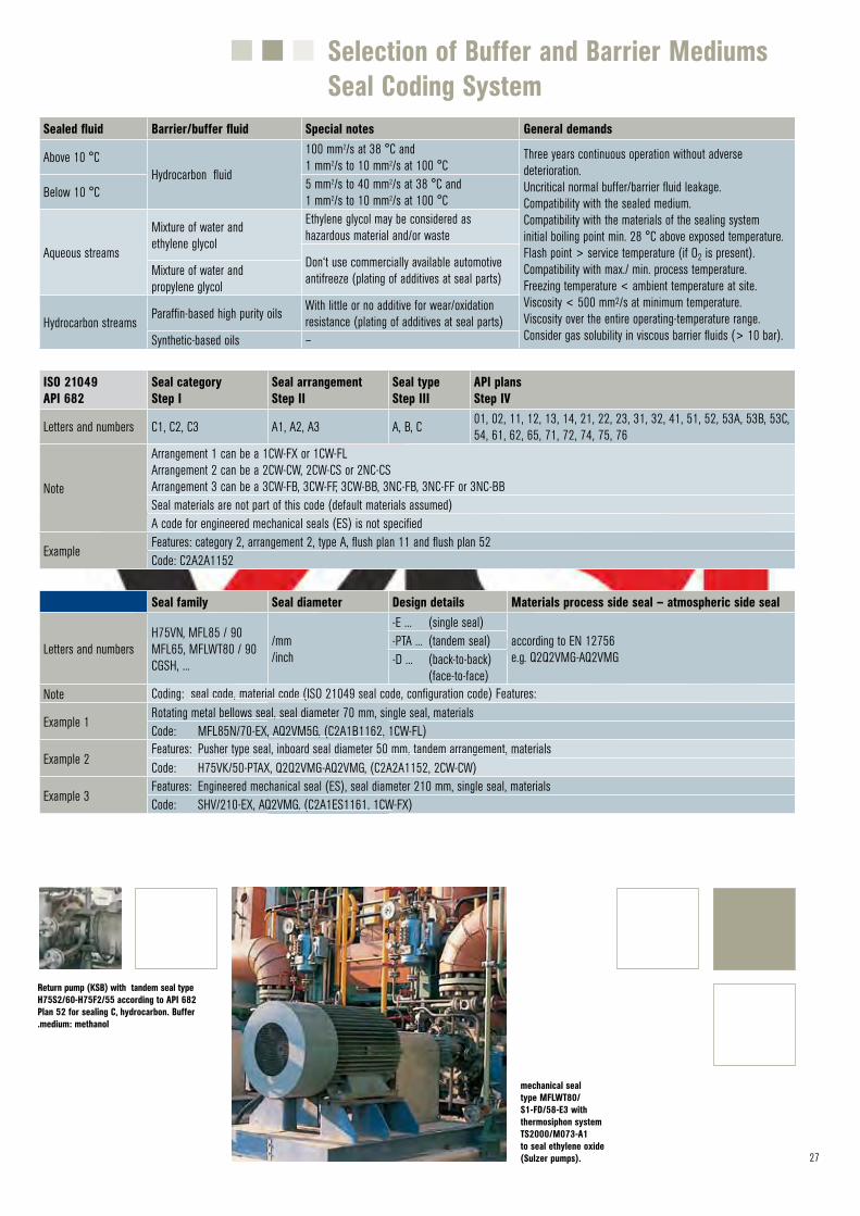
Sealed fluid Barrier/buffer fluid Special notes General demands
Above 10 °CHydrocarbon fluid
100 mm2/s at 38 °C and1 mm2/s to 10 mm2/s at 100 °C
Three years continuous operation without adverse deterioration.Uncritical normal buffer/barrier fluid leakage.Compatibility with the sealed medium.Compatibility with the materials of the sealing systeminitial boiling point min. 28 °C above exposed temperature.Flash point > service temperature (if O2 is present).Compatibility with max./ min. process temperature.Freezing temperature < ambient temperature at site.Viscosity < 500 mm2/s at minimum temperature.Viscosity over the entire operating-temperature range.Consider gas solubility in viscous barrier fluids (> 10 bar).
Below 10 °C 5 mm2/s to 40 mm2/s at 38 °C and1 mm2/s to 10 mm2/s at 100 °C
Aqueous streams
Mixture of water and ethylene glycol
Ethylene glycol may be considered as hazardous material and/or waste
Don‘t use commercially available automotive antifreeze (plating of additives at seal parts)Mixture of water and
propylene glycol
Hydrocarbon streamsParaffin-based high purity oils With little or no additive for wear/oxidation
resistance (plating of additives at seal parts)Synthetic-based oils –
ISO 21049API 682
Seal categoryStep I
Seal arrangementStep II
Seal typeStep III
API plansStep IV
Letters and numbers C1, C2, C3 A1, A2, A3 A, B, C 01, 02, 11, 12, 13, 14, 21, 22, 23, 31, 32, 41, 51, 52, 53A, 53B, 53C, 54, 61, 62, 65, 71, 72, 74, 75, 76
Note
Arrangement 1 can be a 1CW-FX or 1CW-FLArrangement 2 can be a 2CW-CW, 2CW-CS or 2NC-CS Arrangement 3 can be a 3CW-FB, 3CW-FF, 3CW-BB, 3NC-FB, 3NC-FF or 3NC-BBSeal materials are not part of this code (default materials assumed)A code for engineered mechanical seals (ES) is not specified
ExampleFeatures: category 2, arrangement 2, type A, flush plan 11 and flush plan 52 Code: C2A2A1152
Seal family Seal diameter Design details Materials process side seal – atmospheric side seal
Letters and numbersH75VN, MFL85 / 90MFL65, MFLWT80 / 90CGSH, ...
/mm/inch
-E ... (single seal)according to EN 12756e.g. Q2Q2VMG-AQ2VMG
-PTA ... (tandem seal)-D ... (back-to-back)
(face-to-face)Note
Example 1
Example 2
Example 3
Coding: seal code, material code (ISO 21049 seal code, configuration code) Features:Rotating metal bellows seal, seal diameter 70 mm, single seal, materialsCode: MFL85N/70-EX, AQ2VM5G, (C2A1B1162, 1CW-FL)Features: Pusher type seal, inboard seal diameter 50 mm, tandem arrangement, materials Code: H75VK/50-PTAX, Q2Q2VMG-AQ2VMG, (C2A2A1152, 2CW-CW)Features: Engineered mechanical seal (ES), seal diameter 210 mm, single seal, materials Code: SHV/210-EX, AQ2VMG, (C2A1ES1161, 1CW-FX)
27 28
Objectives and Category Details
*) All technical specifications are based on extensive tests and our many years of experience. The diversity of possible applications means, however, that they can serve only as guide values. We must be notified of the exact conditions of application before we can provide any guarantee for a specific case. Subject to change.
API / ISO paragraphs in brackets (** Please also ask for Apitex mechanical (***
seals
Recycle oil pump (BW/IP) with tandem seal H75S2/85-FTA5 according to API 682 plan 52 to seal hydrocarbons. Temperature -13 °C, Barrier fluid: methanol.
Pump (Ruhrpumpen) withseal H75S2/70-FTA1
according to API 682, plan 52.
Medium: C3-fraction; barrier fluid: methanol
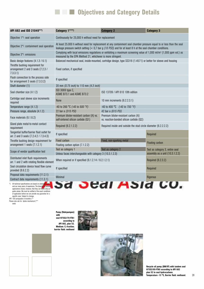
API 682 and ISO 21049**) Category 1***) Category 2 Category 3
Objective 1*): seal operation Continuously for 25,000 h without need for replacement
Objective 2*): containment seal operation At least 25.000 h without need for replacement at any containment seal chamber pressure equal to or less than the seal leakage pressure switch setting (< 0,7 bar g (10 PSI)) and for at least 8 h at the seal chamber conditions.
Objective 3*): emissions Complying with local emissions regulations or exhibiting a maximum screening value of 1,000 ml/m3 (1,000 ppm vol.) as measured by the EPA Method 21, whichever is more stringent.
Basic design features (4.1.3 / 6.1) Balanced mechanical seal, inside-mounted, cartridge design, type SS316 (1.4571) or better for sleeve and housingThrottle bushing requirement for arrangement 2 and 3 seals (7.2.3 / 7.3.3.1)
Fixed carbon, if specified
Flush connection to the process side for arrangement 3 seals (7.3.3.2) If specified
Shaft diameter (1) 20 mm (0.75 inch) to 110 mm (4.3 inch)
Seal chamber size (4.1.2) ISO 3069 type C, ASME B73.1 and ASME B73.2 ISO 13709 / API 610 10th edition
Cartridge seal sleeve size increments required None 10 mm increments (6.2.2.3.1)
Temperature range (4.1.2) -40 to 260 °C (-40 to 500 °F) -40 to 400 °C (-40 to 750 °F)Pressure range, absolute (4.1.2) 22 bar a (315 PSI) 42 bar a (615 PSI)
Face materials (6.1.6.2) Premium blister-resistant carbon (A) vs. self-sintered silicon carbide (Q1)
Premium blister-resistant carbon (A)vs. reaction-bonded silicon carbide (Q2)
Gland plate metal-to-metal contact requirement Required (6.2.1.2.2) Required inside and outside the stud circle diameter (6.2.2.2.2)
Tangential buffer/barrier fluid outlet for arr. 2 and 3 seals (7.2.4.2 / 7.3.4.3) If specified Required
Throttle bushing design requirement for arrangement 1 seals (7.1.2.1)
Fixed carbon Fixed, non-sparking metalFloating carbon
Floating carbon option (7.1.2.2)
Scope of vendor qualification testTest as category 1 Test as category 2 Test as category 3, entire seal
assembly as a unit (10.3.1.2.2)Unless faces interchangeable with category 3 (10.3.1.2.3)Distributed inlet flush requirements arr. 1 and 2 with rotating flexible element When required or if specified (6.1.2.14 / 6.2.1.2.1) Required (6.2.3.2)
Seal circulation device head flow curve provided (8.6.2.2) If specified Required
Proposal data requirements (11.2.1)Minimal Rigorous
Contract data requirements (11.3.1)
29
Profile
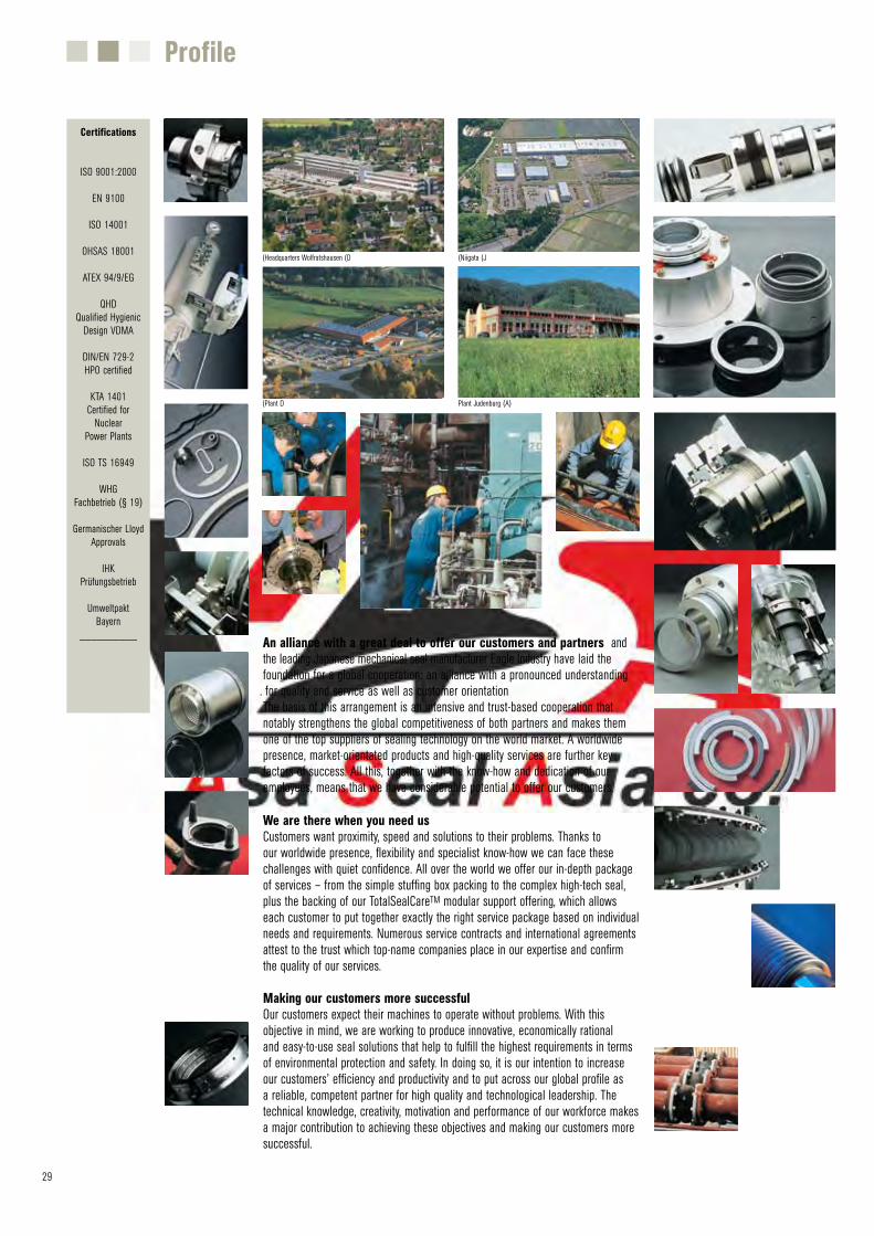
(Headquarters Wolfratshausen (D (Niigata (J
Plant Judenburg (A)(Plant D
An alliance with a great deal to offer our customers and partners and the leading Japanese mechanical seal manufacturer Eagle Industry have laid the foundation for a global cooperation: an alliance with a pronounced understanding. for quality and service as well as customer orientationThe basis of this arrangement is an intensive and trust-based cooperation that notably strengthens the global competitiveness of both partners and makes them one of the top suppliers of sealing technology on the world market. A worldwide presence, market-orientated products and high-quality services are further key factors of success. All this, together with the know-how and dedication of our employees, means that we have considerable potential to offer our customers.
We are there when you need usCustomers want proximity, speed and solutions to their problems. Thanks to our worldwide presence, flexibility and specialist know-how we can face these challenges with quiet confidence. All over the world we offer our in-depth package of services – from the simple stuffing box packing to the complex high-tech seal, plus the backing of our TotalSealCareTM modular support offering, which allows each customer to put together exactly the right service package based on individual needs and requirements. Numerous service contracts and international agreements attest to the trust which top-name companies place in our expertise and confirm the quality of our services.
Making our customers more successful Our customers expect their machines to operate without problems. With this objective in mind, we are working to produce innovative, economically rational and easy-to-use seal solutions that help to fulfill the highest requirements in terms of environmental protection and safety. In doing so, it is our intention to increase our customers’ efficiency and productivity and to put across our global profile as a reliable, competent partner for high quality and technological leadership. The technical knowledge, creativity, motivation and performance of our workforce makes a major contribution to achieving these objectives and making our customers more successful.
Certifications
ISO 9001:2000
EN 9100
ISO 14001
OHSAS 18001
ATEX 94/9/EG
QHDQualified Hygienic
Design VDMA
DIN/EN 729-2HPO certified
KTA 1401Certified for
NuclearPower Plants
ISO TS 16949
WHGFachbetrieb (§ 19)
Germanischer LloydApprovals
IHKPrüfungsbetrieb
UmweltpaktBayern
__________