your partner in power industry - steamturbo.com · microturbine tr100 is particular-ly designed to...
TRANSCRIPT

Your Partner in Power IndustryCompany Profile G – Team a.s.
Equipment for power and heat generation industry

2
ww
w.g-team
.cz
About G-Team, a.s. .....................................................3
Fields of application .....................................................4
Micro Steam Turbines .................................................5
Control valves ............................................................13
Desuperheaters .........................................................15
Bypass valves ...........................................................17
Check (non-return) valves .........................................18
Design engineering ...................................................19
Experimental and Development Department ............21
Installation .................................................................23
Production .................................................................25
Contacts ....................................................................28
Content:

4
Energy Units:
G-Team, a.s. founded in 1992 is an engineering and manufacturing company.
From its beginning, G-Team is involved in the area of heating plant industry
and fossil-fuel power stations and nuclear power plants. We are the leading
supplier in power generation sector specializing in steam and condensate
equipment. Our broad spectrum of supplies and production covers boilers,
steam turbines, valves, pipeline systems, drainage and condensate systems.
Using an integrated approach in production process includes customer
support in engineering (projects) and wide range of services, in particular
installation of machine rooms, boiler plants and pipeline systems.
Fossil-fuel and nuclear power plants
Water industry
Chemistry industry
Food and Beverage industry
Generation units up to 25 MWMicroturbines up to 5 MWBypass stationsReducing stationsSteam generatorsOil systemsCogeneration unitsMonitoringIdentification data:
Legal form: Join-Stock Company
Company registered in the Commercial Register maintained by
the Regional Court in Plzeň, Section B, Insert 1319
Ident. No. (IČO): 45358028, VAT ID (DIČ): CZ 45358028
Engineering: Services:
Valves: Measurement and control:Valves for steam and condensate in generating and industrial installationsControl and shut off valves, check valvesReducing valvesQuick-closing valvesDrain and blowdown valvesSafety valvesBall valvesCheck (non-return) valvesHP and LP steam separatorsSteam traps
Control and optimization of energy processesControl of pressure, temperature and amountMeasurement of energy quantitiesControl, regulation and safety systems
of microturbinesOccupational health and safety management systems
(BOSP)Installation and setting of servo-actuatorsVibration and movement of rotary machines –
ReutlingerDiagnostics of steam traps operation
Studies on energy savingsEnergy equipment designTurnkey projectsEnergy auditsConsulting
Energy equipment installationPipeline system installationSpare parts supplyProject FinancingTrainings within G-Team Academy
ww
w.g-team
.cz
3 4
About G-Team, a.s. Fields of application:

ww
w.g-team
.cz
5
MIC
RO
ST
EA
M T
UR
BIN
ES
w
ww
.g-team.cz
6
Classification
Micro Steam Turbines (TR)
TR with frequency converter TR Hi 150:
TR with “overhung” impeller TR100, TR320, TR560 and TRM3:
TR with “between bearings”impeller TRm:
G-Team, a.s. self-construction
gearbox replaced with high-frequency generator and frequency converter
compact design
only to drive high-frequency generator integrated in turbine
G-Team, a.s. self-construction
simple – modular construction, low installation costs and quick economic pay off solution
efficiency optimization due to partial arc of admission
compact design
high overall thermal efficiency
service life – min. 25 years
simple operation and maintenance
suit to drive generators, feedwater pumps and ventilators
simple installation
classic construction
long service life
mechanical and electronic regulation
multiple stages of blades
suit to drive generators, feedwater pumps, ventilators and sugar-cane mills
For mechanical drives To drive generator With integrated gearbox
Maximum operating parametersInlet steam pressure up to [MPa (a)] 4 4 9 4 9 6
Inlet steam temperature up to [°C] 420 420 550 420 550 450
Output (Exhaust) steam pressure up to [MPa (a)] 0,6 0,6 2,5 0,07–1,4 0,07–1,4 0,9
Power output up to [kW] 80 150 700 3 000 5 000 1 200
Model
p. 7 p. 8 p. 9 p. 10 p. 11 p. 12
Types: TR Hi 150 TR100 TR320 TR560 TRM3 TRm
Equipment for power and heat generation industry

ww
w.g-team
.cz
7
TR100 ww
w.g-team
.cz
8
TR HI 150
Microturbine TR100 is particular-ly designed to drive generators with following power generation.
Gearbox with fixed-on stator of TR100 reduces the speed of impeller to comply with the electric asynchronous genera-tor speed. Base frame including entire oil system and gearbox connected to propelled machine by means of flexible coupling. Mechanical face seals provided reduce steam leaks effectively.
Microturbine is used for automat-ic steam reduction to required value in connection with steam extraction which determines elec-tric output of generator.
Microturbine TR Hi 150 is intend-ed and designed for pressure reduction of water vapour and extremely low steam flow com-plying the requirements for safe and mechanical operation togeth-er with high efficiency. Turbine casing with electric generator stator form a unit without coupling and secondary rotary parts.
Impeller is “overhung” type on rotor of high-frequency electric generator. Mechanical face seals provided reduce steam leaks ef-fectively. Complete oil system is included to supply lubricating and governor oil.
Microturbine is used for automat-ic steam reduction to required value in connection with steam extraction which determines elec-tric output of generator.
11
22
3
5
43
5
64
1/ Steam inlet Power output up to 80 kW
2/ Steam outlet Generator speed 30 000 rpm
3/ Turbine casing Inlet steam pressure up to 4,0 MPa (a)
4/ Base frame Exhaust steam pressure up to 0,6 MPa (a)
5/ High-frequency generator Inlet steam temperature up to 420 °C
1/ Steam inlet Power output up to 150 kW
2/ Steam outlet Generator speed 3 000 rpm
3/ Turbine casing Inlet steam pressure up to 4,0 MPa (a)
4/ Gearbox Exhaust steam pressure up to 0,6 MPa (a)
5/ Asynchronous generator Inlet steam temperature up to 420 °C
6/ Base frame Partial admission of impeller
MIC
RO
ST
EA
M T
UR
BIN
ES

9
TR560
10
1
2
3
4
5
2
3
4
5
6
6
TR320
Microturbine TR560 is particularly designed for isentropic enthalpy droph higher than 120 kJ·kg-1 with two possible partial admis-sions. Machine unit may be used in both backpressure and con-densate system.
Gearbox with fixed-on stator of TR560 reduces the speed of im-peller to comply with the electric asynchronous generator speed. Base frame including entire oil system and gearbox connected to propelled machine by means of flexible coupling. Driven ma-chine is separately placed on concrete foundation. Mechani-cal face seals provided reduce steam leaks effectively.
Microturbine TR560 may be used in both systems – backpressure and condensate. The choice de-pends on the customer and his needs leading to heat and power generation or to use microturbine TR just for power generation.
1
Microturbine TR320 is particular-ly designed to drive generators with following power generation.
Gearbox with fixed-on stator of TR320 reduces the speed of impeller to comply with the electric asynchronous genera-tor speed. Base frame including entire oil system and gearbox connected to propelled machine by means of flexible coupling. Mechanical face seals provided reduce steam leaks effectively.
Microturbine is used for automat-ic steam reduction to required value in connection with steam extraction which determines elec-tric output of generator.
ww
w.g-team
.cz
1/ Steam inlet Power output up to 700 kW
2/ Steam outlet Generator speed 3 000 rpm
3/ Turbine casing Inlet steam pressure up to 9,0 MPa (a)
4/ Gearbox Exhaust steam pressure up to 2,5 MPa (a)
5/ Asynchronous generator Inlet steam temperature up to 550 °C
6/ Base frame Partial admission of impeller
1/ Steam inlet Power output up to 3 000 kW
2/ Steam outlet Speed 1 500 rpm
3/ Turbine casing Inlet steam pressure up to 4,0 MPa (a)
4/ Gearbox Exhaust steam pressure up to 0,07-1,4 MPa (a)
5/ Synchronous generator Inlet steam temperature up to 550 °C
6/ Base frame Partial admission of impeller
MIC
RO
ST
EA
M T
UR
BIN
ES

ww
w.g-team
.cz
11
TRm ww
w.g-team
.cz
1
23
4
5
6
12
1
3
4
5
6
This type of microturbine may be used with gearbox or with-out gearbox with possibility of more blade stages. Mechanical and electronic regulation is suit-able for this type of turbine.
Microturbine consists of welded base frame providing support for turbine body, drive machine (gen-erator, pump or second gearbox for sugar-cane mill), oil system and oil tank. Rotor is placed be-tween two friction bearings. Flex-ible coupling provides connec-tion of rotor shaft and gearbox. Mechanical face seals provided reduce steam leaks effectively and also conducts seal steam.
Shaft speed is automatically gov-erned by microturbine depending on the driven machine require-ments. No regulation of exhaust steam pressure for mechanical actuators.
Microturbine TRM3 is particu-larly designed for isentropic enthalpy drop h higher than 400 kJ/kg with possible one up to three steam extractions. Ma-chine unit may be used in both backpressure and condensate systems.
Turbine casings I., II. and III. stage are fixed to gearbox to reduce turbine wheels speed to comply with generator speed. Base frame including entire oil system and gearbox connected to propelled machine by means of flexible coupling. Driven ma-chine is separately placed on concrete foundation. Mechani-cal face seals provided reduce steam leaks effectively.
1/ Steam inlet Power output up to 5 000 kW
2/ Steam outlet Speed 1 500 rpm
3/ Turbine casing Inlet steam pressure up to 9,0 MPa (a)
4/ Mechanical regulation Exhaust steam pressure up to 0,07-1,4 MPa (a)
5/ Driven machine Inlet steam temperature up to 550 °C
6/ Base frame Controlled extraction after the I. Stage
1/ Steam inlet Power output up to 1 200 kW
2/ Steam outlet Speed 5 000 rpm
3/ Turbine casing Inlet steam pressure up to 6,0 MPa (a)
4/ Mechanical regulation Exhaust steam pressure up to 0,9 MPa (a)
5/ Driven machine Inlet steam temperature up to 450 °C
6/ Base frame
TRM3
2
MIC
RO
ST
EA
M T
UR
BIN
ES

CO
NT
RO
L V
ALV
ES
CO
NT
RO
L VA
LVE
S
1/ Nominal size DN100÷DN400 / DN350÷DN1400 DN100÷DN400 / DN350÷DN1400
2/ Nominal pressure up to PN100 up to PN400
3/ Max. Temperature [°C] 450 610
4/ Valve body Angle Angle
5/ Connection Weld end / Flange Weld end / Flange
6/ Standard ČSN, EN (connection acc. To ANSI, GOST) ČSN, EN (connection acc. To ANSI, GOST)
7/ Characteristic Linear / Equal percentage Linear / Equal percentage
8/ Body material Cast: GP240GH, G17CrMo5-5Forged: P245GH, 13CrMo4-5, 16Mo3
Cast: G17CrMo5-5, G17CrMoV5-10Forged: 13CrMo4-5, 10CrMo9-10, X10CrMoVNb9-1
9/ Kvs [m3/h] 125÷4000 125÷4000
10/ Actuator Electric, Pneumatic, Hydraulic Electric, Pneumatic, Hydraulic
11/ Valve plug Unbalanced / Balanced Unbalanced / Balanced
12/ Application Reducing stations; Bypass stations Reducing stations; Bypass stations
DN15÷DN500 DN80 - DN1400 DN80 - DN1400
up to PN500 up to PN250 up to PN500
610 450 610
Globe „Z“ form „Z“ form
Weld end / Flange Weld end / Flange Weld end / Flange
ČSN, EN (connection acc. To ANSI, GOST) ČSN, EN (connection acc. To ANSI, GOST) ČSN, EN (connection acc. To ANSI, GOST)
Linear / Equal percentage Linear / Equal percentage Linear / Equal percentage
Cast: GP240GH, G17CrMo5-5, G17CrMoV5-10, Forged: P245GH, 13CrMo4-5, 10CrMo9-10, X10CrMoVNb9-1, 16Mo3
Cast: GP240GH, G17CrMo5-5Forged: P245GH, 13CrMo4-5, 16Mo3
Cast: G17CrMo5-5, G17CrMoV5-10Forged: 13CrMo4-5, 10CrMo9-10, X10CrMoVNb9-1
0,01÷2800 125÷4000 125÷4000
Electric, Pneumatic, Hydraulic, Hand wheel Electric, Pneumatic, Hydraulic Electric, Pneumatic, Hydraulic
Unbalanced / Balanced Unbalanced / Balanced Unbalanced / Balanced
Regulation of injected water, seal steam and (water) level in heaters; condensate regulation (level, recirculation)
Feed valve, Bypass stations Bypass stations
AZR 450 AZR 610 AZ 23 AZZ 450 AZZ 610AZZ 450
14
ww
w.g-team
.cz
13

DE
SU
PE
RH
EA
TE
RS
VCHA VCHT PRCH TCH-RT CHP
ww
w.g-team
.cz
16
1/ Nominal size DN100÷DN700 DN25÷DN200
2/ Nominal pressure PN16÷PN400 PN16÷PN100
3/ Max. Steam temperature 610 550
4/ Connection Weld end / Flange Weld end / Flange
5/ Body material P245GH, 16Mo3, 13CrMo4-5, 10CrMo9-10, X10CrMoVNb9-1 P245GH, 16Mo3, 13CrMo4-5, 10CrMo9-10, X10CrMoVNb9-1
6/ Standard ČSN, EN (connection acc. To ANSI, GOST) ČSN, EN (connection acc. To ANSI, GOST)
7/ Cooling system Aerodynamic Aerodynamic
8/ Operating range 10% ÷ 100% of rated flow 15% ÷ 100% of rated flow
9/ Min. steam temperature after cooling Saturation temp. + 7 – 11 °C Saturation temp. + 7 – 11 °C
10/ Min. p injected water and cooled steam [bar] 2 0,7
11/ Application Reducing and Cooling (Desuperheating) stations; Bypass stati-ons; Steam boiler (superheaters, reheaters)
Reducing and Cooling (Desuperheating) stations; Bypass stations; Seal steam; Steam for technological processes
DN250÷DN500 DN125÷DN1400 DN200÷DN700
PN16÷PN100 PN16÷PN160 PN16÷PN160
550 610 610
Weld end / Flange Weld end / Flange Weld end / Flange
P245GH, 16Mo3, 13CrMo4-5, 10CrMo9-10 P245GH, 16Mo3, 13CrMo4-5, 10CrMo9-10, X10CrMoVNb9-1 P245GH, 16Mo3, 13CrMo4-5, 10CrMo9-10, X10CrMoVNb9-1
ČSN, EN (connection acc. To ANSI, GOST) ČSN, EN (connection acc. To ANSI, GOST) ČSN, EN (connection acc. To ANSI, GOST)
Aerodynamic Spray nozzles Atomizing steam
15% ÷ 100% of rated flow 3% ÷ 100% of rated flow 3% ÷ 100% of rated flow
Saturation temp. + 7 – 11 °C Saturation temp. + 7 – 11 °C Saturation temp. + 7 – 11 °C
1 5 3
Reducing and Cooling (Desuperheating) stations; Bypass stations; Steam for technological processes
Reducing and Bypass stations; Turbine backpressure for low pressure losses
Reducing and Cooling (Desuperheating) stations; Turbine extraction; Turbine backpressure; High flow range of steam and cooling water
DE
SU
PE
RH
EA
TE
RS
15

BYPASS STATION
illustration picture
EXTRACTION CHECK VALVES – FGT
18
BY
PA
SS
ES
1/ Nominal size DN100÷DN400 / DN350÷DN1400
2/ Nominal pressure up to PN500
3/ Max. Temperature [°C] 610
4/ Valve body Angle, „Z“ - form
5/ Connection Weld end / Flange
6/ Standard ČSN, EN (connection acc. To ANSI, GOST)
7/ Characteristic Linear / Equal percentage
8/ Body material Cast: GP240GH, G17CrMo5-5, G17CrMoV5-10 Forged: P245GH, 13CrMo4-5, 10CrMo9-10, X10CrMoVNb9-1
9/ Kvs [m3/h] up to 6300
10/ Actuator Electric, Pneumatic, Hydraulic
1/ Nominal size DN80÷DN1200
2/ Nominal pressure up to PN100
3/ Max. Temperature [°C] up to 550
4/ Connection Weld end / Flange
5/ Standard ČSN, EN (connection acc.to ANSI, GOST)
6/ Body material GP240GH, G17CrMo5-5, G17CrMoV5-10
7/ Actuator Pneumatic / hydraulic / self-acting (without actuator)
8/ Application Turbine extraction system
ww
w.g-team
.cz V
ALV
ES
17

DE
SIG
N E
NG
INE
ER
ING
of pipeline systemsin power generation and industry
Design and control of unnormalized pipeline components
Design and documentation of auxiliary steel structures
Isometric drawings for pipeline Balance and functional scheme
Flexibility and thermal expansion analysis
Design Engineering
20
ww
w.g-team
.cz
19
technical feasibility study, ideal balance design of energy equipment and units,
comprehensive project documentation for planning permission (basic design), building design (detail design) and actual design of technological equipment and operation sets for power plants, heating plants and industrial estates in compliance with valid law and technical regulations,
project documentation of repairs and reconstructions of selected technological equipment and operation sets of nuclear power plants classified as BT2 and BT3 acc. to Notice 132/2008 in conformity with requirements of Notice 309/2005,
3D design and space visualization of technological equipment and pipeline systems including safety valves exhausts, steam trap, draining and air-vent in 3D CAD Solid Edge and Smap3D Plant Design,
calculation, piping and instrumentation diagram/drawing showing pipeline components, valves, energy equipment and instrumentation MaR including position of pipeline and auxiliary steel constructions,
design and calculation verification of unnormalized pipeline components through SW ANSYS PROFESSIONAL,
piping Flexibility Analysis through SW CAESAR II
design of pressure and pressure-free vessels, reducing, desuperheating (cooling) and bypass stations including safety pressure equipment in compliance with valid law,
project documentation of pressure tests and cleaning processes after installation,
control algorithm design for regulation, warming-through and commissioning of technological equipment, creation of operating regulations,
G-Team ACADEMY – trainings and seminars.

Feed tank
Testing piping route of desuperheaters
Testing piping route of valves
Microturbine connection points
Circulating water storage tank
Gas boiler with superheater
Circulating water pump
Feed pump
F
TT
T
MM
CC
F
CC ww
w.g-team
.cz
Experimental and Development Department
21 22
Control valves testing testing pipe route designed according to ČSN EN 60534-2-3 provides
flow characteristics and nominal flow coefficients kvs of control valves - DN15 – DN150, up to kv = 100 m3/h.
Desuperheaters testing testing route designed for nozzle optimization of mixing cooler
of superheated steam,
practical verification of newly designed desuperheaters with possibility of size measuring of atomized drops,
testing parameters of reduced inlet steam – temperature up to 240 °C, pressure approx. 12 bar(g), amount up to 4 (÷6) t/h,
testing parameters of inlet cooling water – temperature 15÷100°C, pressure up to 20 bar(g), amount up to 2,0 t/h.
Microturbine testing testing route designed for verification of TR service availability
before despatch to customer (check of operating vibrations and oil temperature in bearings),
testing parameters of inlet steam – temperature 240°C, pressure 12 bar(g), flow 4 (÷6) t/h.
EX
PE
RIM
EN
TA
L AN
D D
EV
ELO
PM
EN
T
DE
PA
RT
ME
NT
Equipment for power and heat generation industry

INS
TA
LLAT
ION
Installation
23 24
ww
w.g-team
.cz
Steam turbine installation Condensing steam turbines Backpressure steam turbines Microturbines Gearbox installation Heavy manipulation into and in installation area
Turbine Current and overhaul repair Spare parts supply
Generator installation Air-cooled generators Hydrogen-cooled generators
Pipeline system installation Pipeline installation from P91, noncorrosive and carbon material Pipeline oil systems Water-steam pipeline High-pressure hydraulic pipeline Industrial gas system Installation and adjustment of control valves Installation and adjustment of servo-actuators
Additional installations Installation of hydrogen system Installation of oil system Installation of integrated oil system Installation of pumps and feed pumps Installation of coolers (desuperheaters) Installation of heaters, tanks and pressure vessels Installation of steam turbine condensers Measurement of energy quantities Vibration and movement of rotary machines Diagnostics of steam traps operation Equipment for power and heat generation industry
ww
w.g-team
.cz wwwwwwwwwwwww
wwwwwwwwwwwwwwwwwwwwwwwwwwwwwwwwwwwwwwwwwwwwwwwwwwwwwwwwwwwwwwwwwwwwwwwwwwwwwwwwwwwwwwww
................gggggggggggggggggggggggggggggggggggggggggggg---tttttttttttttteeeeeeeeeeeeeeeaaaaaaaaaaaaaammmmmmmmmmmmmm...ccccccccccccccccccccccccccccccccccccccccccccccccccccccccczzzzzzzzzzzzzzzzzzzzzzzzzzzzzzzzzzzzzzzzzzzzzzzzzzzzzzzzzzzzz
PR
OD
UC
TIO
N
Production
25 26
ww
w.g-team
.cz
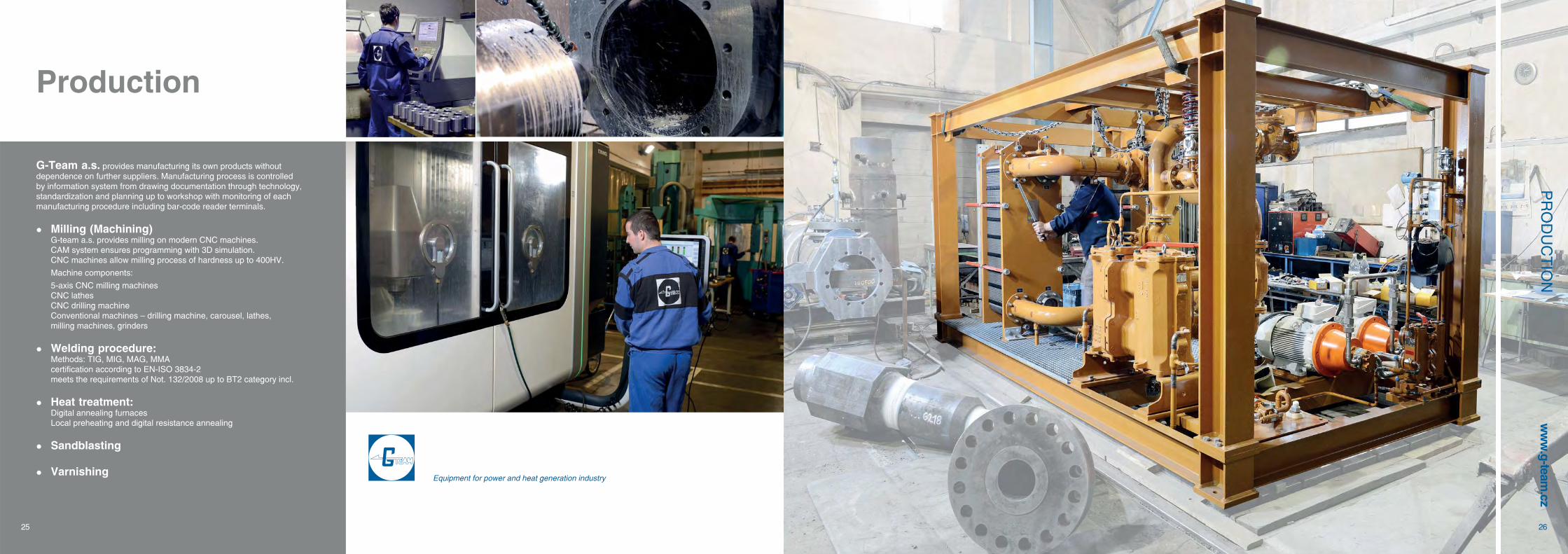
G-Team a.s. provides manufacturing its own products without dependence on further suppliers. Manufacturing process is controlled by information system from drawing documentation through technology, standardization and planning up to workshop with monitoring of each manufacturing procedure including bar-code reader terminals.
Milling (Machining) G-team a.s. provides milling on modern CNC machines. CAM system ensures programming with 3D simulation. CNC machines allow milling process of hardness up to 400HV.
Machine components:
5-axis CNC milling machines CNC lathes CNC drilling machine Conventional machines – drilling machine, carousel, lathes,
milling machines, grinders
Welding procedure: Methods: TIG, MIG, MAG, MMA certification according to EN-ISO 3834-2 meets the requirements of Not. 132/2008 up to BT2 category incl.
Heat treatment: Digital annealing furnaces Local preheating and digital resistance annealing
Sandblasting
VarnishingEquipment for power and heat generation industry

Petrská 2110 00 Prague 1Czech Republicwww.g-team.cz
OfficeHeadquarters and the ProductionČervený mlýn330 23 Pilsen – VochovPh: +420 377 822 401 +420 377 822 410Fax: +420 377 822 425E-mail: [email protected] G
188/
12©
9/2
013
Equipment for power and heat generation industry
Approved Partner ČEZWorkplace Conditions Assessment (WCA)
ČSN EN ISO 3834 – 2:2006
ČSN EN ISO 14001:2005ISO 9001:2008Gold Medal - MSVBrno 2009 (TR Hi150)
ISO 9001 2008 ČSN EN ISO 14001 2005Č ČSN EN ISO 3834Č W k l C ditiW A d P t ČEZA