your primergy econel 40 - fujitsu technology...
TRANSCRIPT

PRIMERGY Econel 40
Operating manual
Introduction
Important notes
Preparing for use
Operation
Troubleshooting and tips
System expansions
Technical data
Index
April 2004 edition
Microsoft, MS, MS-DOS, Windows, and Windows NT are registered trademarks of Microsoft Corporation.
VESA and DPMS are trademarks of Video Electronics Standards Association.
PS/2 is a registered trademark of International Business Machines, Inc.
Pentium is a registered trademark of Intel Corporation, USA.
Kensington Lock and MicroSaver are registered trademarks of ACCO World Corporation.
All other trademarks referenced are trademarks or registered trademarks of their respective owners, whose protected rights are acknowledged.
Copyright Fujitsu Siemens Computers GmbH 2004
All rights, including rights of translation, reproduction by printing, copying or similar methods, in part or in whole, are reserved.
Offenders will be liable for damages.
All rights, including rights created by patent grant or registration of a utility model or design, are reserved.
Delivery subject to availability. Right of technical modification reserved.
This manual was produced by cognitas. Gesellschaft für Technik-Dokumentation mbH www.cognitas.de

Contents Your PRIMERGY Econel 40.............................................................................................................1 Features ............................................................................................................................................2 Notational conventions ......................................................................................................................3 Target group......................................................................................................................................3
Important notes ...............................................................................................................................5 Safety ................................................................................................................................................5
Energy saving, disposal and recycling .......................................................................................5 CE marking................................................................................................................................5 FCC Class B Compliance Statement .........................................................................................6
Transporting the server......................................................................................................................6 Cleaning the server............................................................................................................................6
Preparing for use.............................................................................................................................7 Unpacking and checking the delivery.................................................................................................7 Steps for initial setup .........................................................................................................................7 Setting up the server..........................................................................................................................8 Connect the monitor, mouse and keyboard .......................................................................................8
Connecting the monitor..............................................................................................................8 Connecting the mouse...............................................................................................................9 Connecting a keyboard ..............................................................................................................9
Connecting the server to the mains voltage .....................................................................................10 Initial switch-on: Software will be installed .......................................................................................11
Switching on monitor and server..............................................................................................11 Configuring the server .....................................................................................................................13
Configuration with ServerStart .................................................................................................13 Configuration without ServerStart ............................................................................................13
Connecting external devices............................................................................................................14 Ports on the server ..................................................................................................................15 Connecting external devices to the serial port..........................................................................16 Connecting external devices to the parallel port.......................................................................16 Connecting external devices to the USB port ...........................................................................17
Operation .......................................................................................................................................19 Switching the server on............................................................................................................19 Switching the server off............................................................................................................19
Indicators on the server ...................................................................................................................20 Keyboard .........................................................................................................................................21
Important keys and key combinations......................................................................................22 Working with floppy disks ................................................................................................................23 Settings in BIOS Setup....................................................................................................................24 Property and data protection............................................................................................................24
Anti-theft protection and lead-sealing.......................................................................................24 BIOS setup security functions..................................................................................................25
Troubleshooting and tips..............................................................................................................27 Installing new software ....................................................................................................................27 Power-on indicator remains unlit after you have switched on your device........................................27 The screen stays blank....................................................................................................................28 No mouse pointer displayed on the screen ......................................................................................29 The floppy disk cannot be read or written ........................................................................................29 Time and/or date is not correct ........................................................................................................30 Error messages on the screen.........................................................................................................30

Contents
System expansions....................................................................................................................... 31 Information about boards ........................................................................................................ 31
Opening the casing ......................................................................................................................... 32 Closing the casing........................................................................................................................... 33 Installing and removing a board ...................................................................................................... 34
Installing a board..................................................................................................................... 34 Removing a board................................................................................................................... 36
Low-Profile boards .......................................................................................................................... 38 Mounting slot adapter.............................................................................................................. 38 Removing slot adapter ............................................................................................................ 38 Installing and removing drives ................................................................................................. 39 Removing the front panel ........................................................................................................ 40 Attaching the front panel ......................................................................................................... 41 Installing an accessible drive................................................................................................... 42 Removing an accessible drive................................................................................................. 44 Changing the floppy disk drive ................................................................................................ 47 Installing or removing the hard disk drive ................................................................................ 50
Extensions to the system board ...................................................................................................... 54 Removing the power supply .................................................................................................... 54 Upgrading main memory ......................................................................................................... 54 Replacing processor................................................................................................................ 54 Replacing lithium battery ......................................................................................................... 55 Swinging the power supply in .................................................................................................. 55
Technical data ............................................................................................................................... 57
Index .............................................................................................................................................. 59

1
Your PRIMERGY Econel 40... ...is available with various configuration levels with different hardware and software. In addition, you can install accessible drives (e.g. DVD drive), hard disk drives and other boards. This operating manual tells you how to put your server into operation and how to operate it in daily use. This description applies for all configuration levels. Depending on the configuration level chosen some of the hardware components described may not be available on your server. Please observe the notes on your operating system. Your server has a number of security features to ensure that no unauthorized persons can access your data. The security functions in the BIOS Setup also allow you to protect your data by means of passwords. In addition, you can also mechanically lock your server. ServerStart allows you under some operating systems to easily and quickly install the latest drivers and operating system extensions with a few mouse clicks. Further information on this server is provided: • in the "Safety and Ergonomics" manual • in the "Warranty" manual • in the operating manual for the monitor • in the technical manual for the D1755 system board • in the "BIOS Setup" manual • in the "PRIMERGY Econel 40 Quickstart" poster • in your operating system documentation • in the information files (e.g. *.TXT, *.DOC, *.WRI, *.HLP)
i
Some of the manuals listed can be found on the "ServerBooks" CD provided with your server. These manuals can be read and printed with Acrobat Reader, also contained on the CD.
Keep this operating manual together with your device. If you pass on the device to third parties, you should include this manual.
Your PRIMERGY Econel 40... Features
2
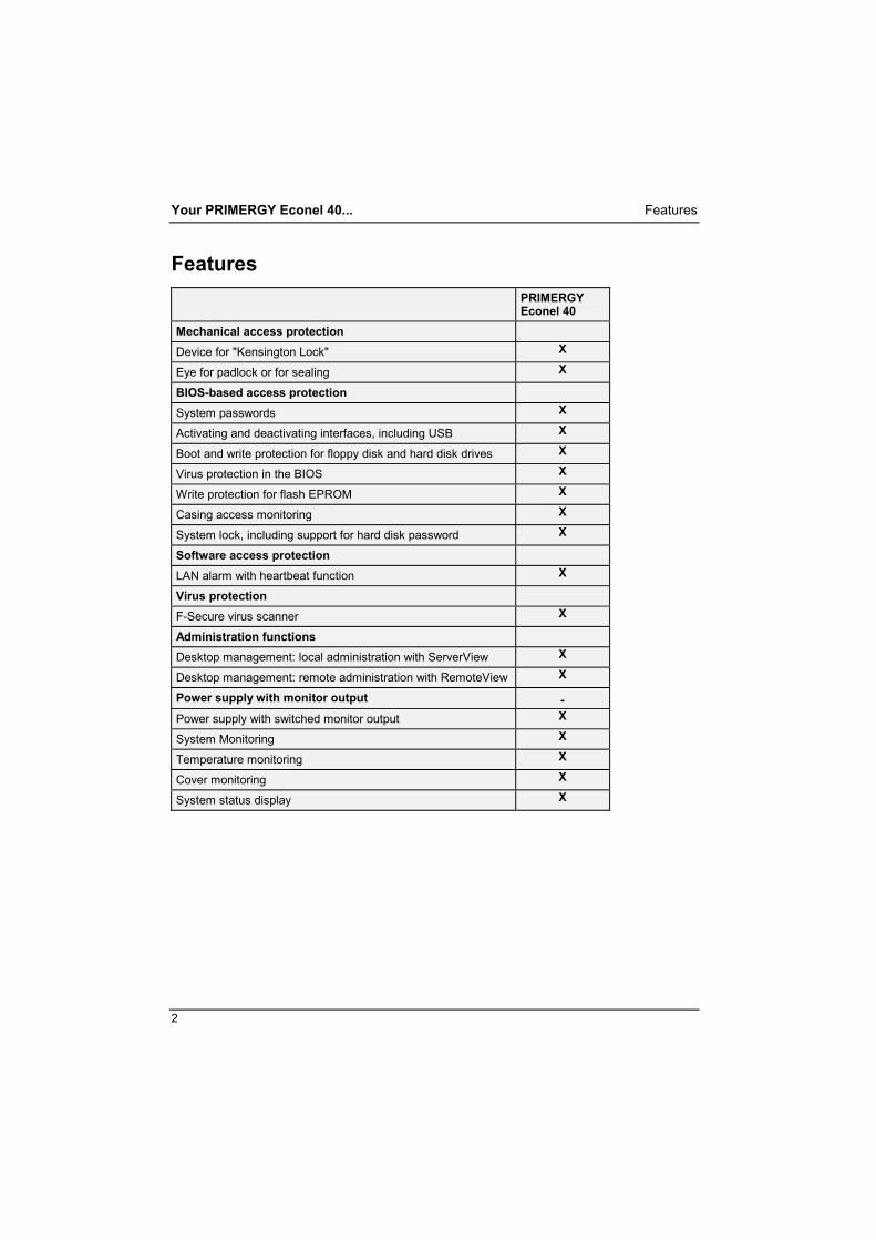
Features PRIMERGY
Econel 40 Mechanical access protection Device for "Kensington Lock" X
Eye for padlock or for sealing X
BIOS-based access protection
System passwords X
Activating and deactivating interfaces, including USB X
Boot and write protection for floppy disk and hard disk drives X
Virus protection in the BIOS X
Write protection for flash EPROM X
Casing access monitoring X
System lock, including support for hard disk password X
Software access protection
LAN alarm with heartbeat function X
Virus protection
F-Secure virus scanner X
Administration functions
Desktop management: local administration with ServerView X
Desktop management: remote administration with RemoteView X
Power supply with monitor output - Power supply with switched monitor output X
System Monitoring X
Temperature monitoring X
Cover monitoring X
System status display X

Notational conventions Your PRIMERGY Econel 40...
3
Notational conventions The meanings of the symbols and fonts used in this manual are as follows:
!
CAUTION! indicates information which is important for your health or for preventing physical damage.
i
indicates important information which is required to use the system properly.
Ê Text which follows this symbol describes activities that must be
performed in the order shown. Italics indicates commands or menu items
"Quotation marks" indicate names of chapters and terms that are being emphasized.
Target group This operating manual is intended for those responsible for installing the hardware and ensuring that the system runs smoothly. The operating manual contains all the information required for installing your PRIMERGY Econel 40. To understand the different expansion options, you need a knowledge of hardware and data transmission, as well as basic knowledge of the operating system used.

5
Important notes In this chapter you will find information regarding safety which it is essential to take note of when working with your server.
Safety
!
CAUTION! Pay attention to the information provided in the "Safety and Ergonomics" manual and in the following safety notes. During installation and before operating the device, please observe the instructions on environmental conditions in the "Technical data" chapter as well as the instructions in the "Preparing for use" chapter. You may only operate the device, if the rated voltage for the device is set to the local mains voltage. Check the rated voltage set for this device (see the "Preparing for use" chapter). The main switch and the ON/OFF button do not disconnect the server from the mains voltage. To completely disconnect the mains voltage, remove the power plug from the grounded mains outlet. Remove the power plug before opening the unit. Replace the lithium battery on the system board in accordance with the instructions in the "Extensions to the system board" - "Replacing lithium battery" chapter. Caution, components in the system can get very hot.
Energy saving, disposal and recycling Further information can be found on the CD provided with your computer.
CE marking
The shipped version of this device complies with the requirements of the EEC directives 89/336/EEC "Electromagnetic compatibility" and 73/23/EEC "Low voltage directive".

Important notes Transporting the server
6
FCC Class B Compliance Statement The following statement applies to the products covered in this manual, unless otherwise specified herein. The statement for other products will appear in the accompanying documentation.
NOTE: This equipment has been tested and found to comply with the limits for a "Class B" digital device, pursuant to Part 15 of the FCC rules and meets all requirements of the Canadian Interference-Causing Equipment Regulations. These limits are designed to provide reasonable protection against harmful interference in a residential installation. This equipment generates, uses and can radiate radio frequency energy and, if not installed and used in strict accordance with the instructions, may cause harmful interference to radio communications. However, there is no guarantee that interference will not occur in a particular installation. If this equipment does cause harmful interference to radio or television reception, which can be determined by turning the equipment off and on, the user is encouraged to try to correct the interference by one or more of the following measures: Reorient or relocate the receiving antenna. Increase the separation between equipment and the receiver. Connect the equipment into an outlet on a circuit different from that to which the receiver is
connected. Consult the dealer or an experienced radio/TV technician for help. Fujitsu Siemens Computers GmbH is not responsible for any radio or television interference caused by unauthorized modifications of this equipment or the substitution or attachment of connecting cables and equipment other than those specified by Fujitsu Siemens Computers GmbH. The correction of interference caused by such unauthorized modification, substitution or attachment will be the responsibility of the user. The use of shielded I/O cables is required when connecting this equipment to any and all optional peripheral or host devices. Failure to do so may violate FCC rules.
Transporting the server
!
CAUTION! Transport all parts separately in their original packaging or in a packaging which protects them from knocks and jolts, to the new site. Do not unpack them until all transportation maneuvers are completed.
Cleaning the server
!
CAUTION! Turn off all power and equipment switches and pull the power plug out of the grounded mains outlets. Do not clean any interior parts yourself, leave this job to a service technician. Do not use any cleaning agents that contain abrasives or may corrode plastic. Ensure that no liquid enters the system.
Wipe the casing with a dry cloth. If particularly dirty, use a cloth that has been moistened in mild domestic detergent and then carefully wrung out. Use disinfectant wipes to clean the keyboard and the mouse.

7
Preparing for use
!
CAUTION! Please take note of the safety information in the "Important notes" chapter.
Unpacking and checking the delivery It is recommended not to throw away the original packaging material! It may be required for reshipment at some later date. Ê Unpack all the individual parts. Ê Check the delivery for damage incurred during transportation. Ê Check whether the delivery agrees with the details in the delivery note. Should you discover that the delivery does not correspond to the delivery note, notify your local sales outlet immediately.
Steps for initial setup Only a few steps are necessary to put your new server into operation for the first time:
− Select location for server and set up server − Connect the monitor, mouse and keyboard − Check the voltage at the mains outlet and connect the server to an electrical outlet. Switch
the server on You will learn more about the individual steps in the following sections
i
External devices If you have received other devices in addition to your server (e.g. a printer or a modem), do not connect these until after the initial installation. The following sections contain a description of how to connect these external devices: "Connecting external devices to the serial port" and "Connecting external devices to the parallel port".
Drives and boards If you have received drives or boards with your server, please do not install them until after first-time setup. How to install drives and boards is described in the "System expansions" chapter.

Preparing for use Setting up the server
8
Setting up the server
!
CAUTION! When installing your server, give consideration to the recommendations and safety notes in the "Safety and Ergonomics" booklet. Set up the server only in its correct orientation. The points to observe are illustrated on the following pages. We recommend that you place your device on a surface with good anti-slip qualities. In view of the multitude of different finishes and varnishes used on furniture, it is possible that the rubber feet will mark the surface they stand on. Do not expose the server to extreme environmental conditions (see "Technical data" chapter). Provide at least 200 mm of clearance in front of, to the left of, and behind the ventilator area of the server to ensure adequate ventilation. In order to avoid overheating, do not cover the ventilation area of the monitor or the server. Do not place several servers one above the other.
Connect the monitor, mouse and keyboard The ports for the monitor, mouse, and keyboard are on the rear of the server (see "Ports on the server" chapter).
Connecting the monitor Ê Follow the instructions contained in the monitor manual to prepare the monitor for operation
(e.g. connecting cables).
1 2
Ê Depending on the connector, plug the monitor's power cable into either the server (1) or the
mains outlet (2).

Connect the monitor, mouse and keyboard Preparing for use
9
i
It is recommended to connect the monitor power cable to the server monitor socket. The monitor is then switched off automatically when you switch the server off. The monitor is not switching off with the system if it is connected to a mains outlet. Switch off the monitor with its own ON/OFF button.
!
CAUTION! The monitor power cable may only be connected to the server monitor socket if the monitor current consumption is smaller than 1,5 A with 230 V or 3 A with 115 V. The values for the monitor current consumption can be found in the technical data on the monitor or in the operating manual for the monitor.
Ê Plug the data cable into the monitor port of the server.
Connecting the mouse Depending on the equipment level selected, your server will be supplied with a PS/2 mouse or a USB mouse.
Connecting a PS/2 mouse
Ê Connect the PS/2 mouse to the PS/2 mouse port of the server.
Connecting USB mouse
Ê Connect the USB mouse to the USB port of the server.
i
If you do not attach a mouse at the PS/2 mouse port, you can disable the mouse controller in the BIOS Setup in order to free the IRQ12 for a different application.
Connecting a keyboard Depending on the equipment level selected, your server will be supplied with a standard keyboard or a USB keyboard.
Connecting standard keyboard Use the supplied keyboard cable only. Ê Plug the other end of the keyboard cable (square plug) into the socket on the underside of the
keyboard.
Ê Plug the round plug of the keyboard cable into the keyboard port on the server.
Connecting USB keyboard Use the supplied keyboard cable only. Ê Plug the other end of the keyboard cable (square plug) into the socket on the underside of the
keyboard.
Ê Insert the rectangular USB plug of the keyboard cable into the USB port of the server.

Preparing for use Connecting the server to the mains voltage
10
Connecting the server to the mains voltage The server is equipped with a main switch and a wide range power supply. This means that manual voltage setting is not necessary.
!
CAUTION! The wide-range power supply automatically sets itself to the correct voltage within the range from 100 V to 240 V.
Ê Ensure that the local mains voltage is within the range of 100 V to 240 V.
1
2
Ê Connect the power cable to the server (1). Ê Plug the power plug into the grounded mains outlet (2).

Initial switch-on: Software will be installed Preparing for use
11
Initial switch-on: Software will be installed If the server is connected to a network, the network protocol is required as well as the user and server details. Contact your network administrator if you have any questions about these settings. When you switch on your server for the first time, the supplied software is installed and configured. You should plan some time for this, as this process must not be interrupted.
!
CAUTION! Once the installation has been started the server must not be switched off! During installation the server may only be rebooted when you are requested to do so! Otherwise the installation will be not be performed correctly. If a fault occurs during the installation, the contents of the hard disk must be completely restored.
You may require the Windows license number during installation. This number is located on a sticker on your server.
Switching on monitor and server Ê Switch the monitor on (see the operating manual for the monitor). Ê Switch your server on. To do this, follow the instructions below.
i
Additionally to the ON/OFF button on the front a main switch at the rear of the server is available.
Preparing for use Initial switch-on: Software will be installed
12
0
I
1
2
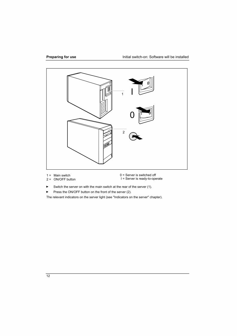
1 = Main switch 2 = ON/OFF button
0 = Server is switched off I = Server is ready-to-operate
Ê Switch the server on with the main switch at the rear of the server (1). Ê Press the ON/OFF button on the front of the server (2). The relevant indicators on the server light (see "Indicators on the server" chapter).

Configuring the server Preparing for use
13
Configuring the server This section contains information about configuring the server and installing the operating system.
i
Please make sure that the energy-saving functions are disabled in BIOS setup during server operation.
Configuration with ServerStart
Configuring the SATA RAID controller The server is equipped with an onboard SATA controller with RAID functionality. Configure the RAID before you begin with ServerStart.
i
To configure the RAID, the controller has its own utility. For further information see the manual "Promise SATA S150 TX4" on the ServerBooks CD (choose "Controllers" from the menu).
With the ServerStart CD provided, you can configure the server and install the operating system in a convenient manner. The menu-guided configuration includes the server configuration with the SCU and the SATA RAID controller configuration with the GAM (Global Array Manager). To find out how to operate ServerStart and for further information, refer to the corresponding manual. If you use ServerStart, you can skip the following sections on how to configure the server and install the operating system. Continue with section "Connecting external devices".
Configuration without ServerStart
Configuring the SATA RAID controller The server is equipped with an onboard SATA controller with RAID functionality.
i
To configure the RAID, the controller has its own utility. For further information see the manual "Promise SATA S150 TX4" on the ServerBooks CD (choose "Controllers" from the menu).
Configuring the PCI SATA RAID controller If your server is fitted with an additional PCI RAID controller, you must configure it as described in the related documentation.
Configuring the PCI SCSI controller If your server is fitted with an additional PCI SCSI controller, you must configure it as described in the related documentation.
Installing the operation system Ê Insert the installation disk and the CD of the operating system you want to install. Ê Reboot the server. Ê Follow the instructions on the screen and in the manual for the operating system.

Preparing for use Connecting external devices
14
If your server is equipped with a RAID controller, then please read how to install the desired operating system in the related manual.
Connecting external devices
!
CAUTION! Read the documentation on the external device before connecting it. The power plug must be removed before connecting external devices, apart from devices with USB interfaces. Do not either connect or disconnect cables during storms. Always take hold of the actual plug. Never unplug a cable by pulling the cable itself. Connect and disconnect the cables in the order described below.
Connecting cables • Turn off all power and equipment switches. • Remove all power plugs from the mains outlets. • Plug all cables into the server and peripherals. You must observe the information provided in
the "Important notes" chapter. • Plug all data communication cables into the utility sockets. • Plug all power cables into the grounded mains outlets.

Connecting external devices Preparing for use
15
Disconnecting cables • Turn off all power and equipment switches. • Remove all power plugs from the mains outlets. • Unplug all data communication cables from the utility sockets. • Disconnect all cables at the server and at the peripherals.
i
Devices with USB interfaces are hot-pluggable. This allows cables from these devices to be connected and disconnected with the system switched on. Additional information can be found in the "Connecting external devices to the USB port" section and in the documentation for the corresponding devices.
Ports on the server The ports for external devices are on the rear of the server. The ports available on your Server depend on the configuration level you have selected. The standard ports are marked with the symbols shown below (or similar). Exact details of the position of the ports are supplied in the technical manuals for the boards.
Keyboard port, purple
PS/2 mouse port, green
1
Serial port 1, teal or turquoise
Parallel port/Printer, burgundy
Monitor port, blue
SCSI connection
USB - Universal Serial Bus, black LAN
LAN connector
i
Some of the devices that you connect require special drivers (see the operating system and device documentation).

Preparing for use Connecting external devices
16
Connecting external devices to the serial port External devices can be connected to the serial port (e.g. a modem). Ê Connect the data cable to the external device.
Ê Connect the data cable to the serial port . For an exact description of how to connect external devices to the serial port, please refer to the device documentation.
i
Settings of the serial port If you need to change the settings of the serial port (e.g. address, interrupt), you can do so in the BIOS Setup. The settings for the port are described in the technical manual for the D1755 system board or in the "BIOS Setup" manual. Device drivers The devices connected to the serial port require drivers. Your operating system already includes many drivers. Nevertheless, if the driver you need is not on the hard disk, please install it from the data carrier supplied with the device or with the application program.
Connecting external devices to the parallel port External devices can be connected to the parallel port (e.g. a printer). Ê Connect the data cable to the external device.
Ê Connect the data cable to the parallel port . For an exact description of how to connect external devices to the parallel port, please see the device documentation.
i
Settings of the parallel port If you need to change the settings of the parallel port (e.g. address, interrupt), you can do so in the BIOS Setup. The settings for the port are described in the technical manual for the D1755 system board or in the "BIOS Setup" manual.
Device drivers The devices connected to the parallel port require drivers. Your operating system already includes many drivers. Nevertheless, if the driver you need is not on the hard disk, please install it from the data carrier supplied with the device or with the application program.

Connecting external devices Preparing for use
17
Connecting external devices to the USB port You can connect a wide range of external devices to the USB port (e.g. printer, scanner, modem or keyboard).
i
Devices with USB interfaces are hot-pluggable. This allows cables from those devices to be connected and disconnected with the system switched on. Additional information can be found in the documentation for the corresponding devices.
Ê Connect the data cable to the external device.
Ê Connect the data cable to the USB port .
i
Device drivers The devices you connect to the USB port usually require no driver of their own, as the required software is already included in the operating system. However, if the device requires its own software, please install it from the data carrier provided with the device.


19
Operation Switching the server on Ê If necessary, switch the monitor on (see the operating manual for the monitor). Ê Switch the server on with the main switch at the rear of the server. Ê Press the ON/OFF button on the front of the server. The power-on indicator lights green (see "Indicators on the server" chapter) and the server is started.
Switching the server off Ê Shut down the operating system properly. Ê If the server operating system does not switch off automatically, use the ON/OFF button to
switch off the server when requested. Ê Switch the server off at the main switch at the rear of the server.
!
CAUTION! The main switch and the ON/OFF button do not disconnect the server from the mains voltage. To completely disconnect the mains voltage, remove the power plug from the socket.
Ê If necessary, switch the monitor off (see the operating manual for the monitor).
Placing a server (with soft power off function) in a ready-to-operate state by means of software With the soft power off function the server automatically switches off (standby) or switches into the energy-saving mode after the operating system is shut down. Requirements: Your system must support switching off with software and this functionality must be enabled in BIOS Setup. The soft power off software may also need to be installed on Windows NT systems. You can also switch your server into the standby mode via ServerView- and/or RemoteView.
Operation Indicators on the server
20
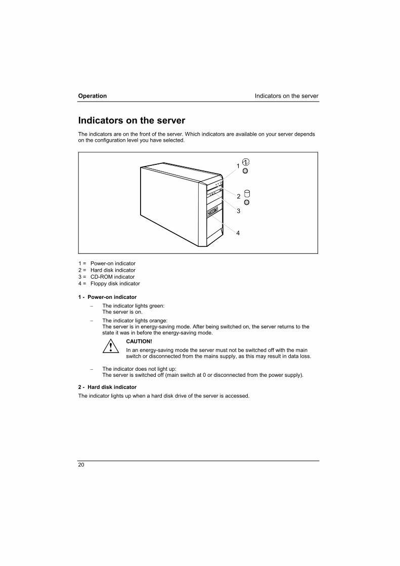
Indicators on the server The indicators are on the front of the server. Which indicators are available on your server depends on the configuration level you have selected.
3
4
1
2
1 = Power-on indicator 2 = Hard disk indicator 3 = CD-ROM indicator 4 = Floppy disk indicator
1 - Power-on indicator − The indicator lights green:
The server is on. − The indicator lights orange:
The server is in energy-saving mode. After being switched on, the server returns to the state it was in before the energy-saving mode.
!
CAUTION! In an energy-saving mode the server must not be switched off with the main switch or disconnected from the mains supply, as this may result in data loss.
− The indicator does not light up:
The server is switched off (main switch at 0 or disconnected from the power supply).
2 - Hard disk indicator The indicator lights up when a hard disk drive of the server is accessed.

Keyboard Operation
21
3 - CD-ROM indicator The indicator lights up when the CD-ROM drive of the server is accessed. You may only remove the CD when the indicator is dark.
4 - Floppy disk indicator The indicator lights up when the floppy disk drive of the server is accessed. You may only remove the floppy disk when the indicator is unlit.
Keyboard
1
3 4 5
2
1 = Function keys 2 = ON/OFF button (optional) 3 = Alphanumeric keypad
1 = Cursor keys 2 = Numeric keypad (calculator keypad)
i
The illustrated keyboard is an example and may differ from the model you use.

Operation Keyboard
22
Important keys and key combinations The following description of keys and key combinations refers to MS Windows. Details of other keys and key combinations can be found in the documentation of the relevant application program.
ON/OFF button (optional) Depending on the setting in the BIOS Setup, the system can be switched on, off, or on and off with this button. Some operating systems allow you to configure additional functions of the ON/OFF button in the Control Panel. On some keyboards the ON/OFF button can only be used with ACPI. Otherwise the key is inoperative. The system board must support this function.
Enter key confirms the marked selection. The enter key is also referred to as the "Return" key.
Start key calls up the Windows Start menu.
Menu key invokes the menu for the marked item (Windows).
Shift key enables upper-case letters and the upper key symbols to be used.
Alt Gr
Alt Gr (e.g. German keyboard) produces a character shown on the right-hand side of a key (e.g. the character @ on the key [Q]).
NumLock
Num Lock key by pressing the Num Lock key you switch between the Numeric keypad cursor control functions and digit or comma functions. When the Num Lock indicator is lit the digit and comma keys are active. When the Num Lock indicator is not lit the cursor control functions are active in the Numeric keypad.
Ctrl
Ctrl key starts key combination actions. The [Ctrl] key is also called "Control" or "Control key".
Ctrl Alt Del
Warm boot restarts your server. Press simultaneously the keys [Ctrl] + [Alt] + [Del]. Under some operating systems the Task Manager appears first. Then you must press all three keys again to re-boot.

Working with floppy disks Operation
23
Working with floppy disks
i
Follow the instructions supplied by the vendor of the floppy disks. Never clean the floppy disk drives with cleaning floppy disks. Any attempt would destroy the read/write head in the disk drive within 20 seconds.
32
1
5
64
7
1 = Insertion direction 2 = Label area 3 = Write protection tab for a 1.44 Mbyte floppy disk 4 = Identification of a 1.44 MB floppy disk or write protect switch on a 120 MB floppy disk 5 = Eject button for inserted floppy disks 6 = Floppy disk is write-protected 7 = Floppy disk is not write-protected
To insert a floppy disk: Ê Push the floppy disk into the drive in the insertion direction (1) until it engages. The label
should be facing upward.
To remove a floppy disk: Ê Push the eject button (5).
Protect the floppy disk against being overwritten or erased Ê Slide the write-protect slider into position (6). The hole is now visible.
Deactivate write protection Ê Slide the write-protect slider into position (7). The hole is now covered.

Operation Settings in BIOS Setup
24
Settings in BIOS Setup In BIOS Setup you can set the system functions and the hardware configuration of the server. When the server is delivered, the default entries are valid (see "BIOS Setup" manual and if necessary technical manual for the D1755 system board). You may customize these settings to your requirements in the BIOS Setup.
Property and data protection Software functions and mechanical locking offer a broad range of functions for protecting your server and your personal data from unauthorized access. You can also combine these functions.
Anti-theft protection and lead-sealing There are three ways to protect your server from theft: • with the Kensington Lock device and with a Kensington MicroSaver • with a chain (lead-seal) • with a (pad)lock To prevent unauthorized persons from opening the casing, the casing can be sealed. Ê To do this, feed the sealing chain (a) through the large eye and the small eye and seal the
chain with the lead seal. You can also attach a padlock to the large eye to prevent unauthorized opening of the casing. You can also use this eye to anchor the casing if necessary.
a

Property and data protection Operation
25
BIOS setup security functions The Security menu in BIOS Setup offers you various options for protecting your personal data against unauthorized access, e.g.: • Preventing unauthorized BIOS Setup entry • Preventing unauthorized system access • Preventing unauthorized access to the settings of boards with their own BIOS • Preventing system booting from the floppy disk drive • Activating virus warnings • Preventing unauthorized writing of floppy disks • Protecting BIOS from being overwritten • Protecting the server from being switched on by an external device You can also combine these functions. You will find a detailed description of the Security menus and how to assign passwords in the technical manual for the D1755 system board or in the "BIOS Setup" manual.

27
Troubleshooting and tips
!
CAUTION! Take note of the safety notes in the "Safety and Ergonomics" manual and in the "Preparing for use" chapter, when you connect or disconnect cables.
If a fault occurs, try to correct it as described in the following places: • in this chapter • in the documentation of the connected devices • in the help systems of the software used • in the documentation of your operating system If you fail to correct the problem, proceed as follows: Ê Switch the server off. Ê Make a note of the steps and the circumstances that led to the fault. Ê Make a note of any error messages displayed. Ê Note the ID number of your device. This number can be found on the type rating plate on the
back of the casing. Ê Contact your sales outlet or our customer service center.
Installing new software When installing programs or drivers, important files may be overwritten and modified. To be able to access the original data in the event of any problems following installation, you should backup your hard disk prior to installation.
Power-on indicator remains unlit after you have switched on your device This may be due to the following:
The mains voltage supply is faulty Ê Check whether the power cable is plugged properly into the server and mains outlet. Ê Switch your server on.
Internal power supply overloaded Ê Pull the power plug of the server out of the mains outlet. Ê Wait for a moment. Ê Plug the power plug into the grounded mains outlet again. Ê Switch your server on.

Troubleshooting and tips
28
The screen stays blank If your screen remains blank this may be due to the following:
Monitor is switched off Ê Switch your monitor on.
Power saving has been activated (screen is blank) Ê Press any key on the keyboard. or Ê Deactivate the screen saver. Enter the appropriate password.
Brightness control is set to dark Ê Adjust the brightness control. For detailed information, please refer to the operating manual
supplied with your monitor.
Power cable not connected Ê Switch off the monitor and the server. Ê Check that the monitor power cable is properly connected to the monitor and, depending on the
connector, to the server or to a grounded mains outlet. Ê Check whether the power cable of the server is properly connected to the server and to the
mains outlet. Ê Switch on the monitor and the server.
Monitor cable not connected Ê Switch off the monitor and the server. Ê Check that the monitor cable is properly connected to the server and monitor. Ê Switch on the monitor and the server.
Wrong monitor has been set under Windows 2000 Ê Reboot the server. Ê If the message Starting Windows appears, press function key [F8]. The Windows 2000 Advanced Options Menu appears. Ê Select Safe Mode or Safe Mode with Network. Ê Set the correct values for the attached monitor as described in the operating manual of the
monitor by selecting Start - Settings - Control Panel - Display - Settings.

Troubleshooting and tips
29
Wrong monitor has been set under Window XP Ê Reboot the server. Ê Press [F8] while the system is booting. Either the Windows Advanced Start Options menu or the menu for selecting the operating system appears. Ê If the menu for selecting the operating system appears, press [F8]. Ê Select Safe Mode or Safe Mode with Network. Ê Set the correct values for the attached monitor as described in the operating manual of the
monitor by selecting Start - Settings - Control Panel - Display and then the Appearance, Themes, Settings tabs.
The wrong RAM modules have been inserted See the technical manual for the D1755 system board for information on which memory modules can be used.
No mouse pointer displayed on the screen Ê Shut down the operating system properly. Ê Switch the server off. Ê Check that the mouse cable is properly connected to the system unit.
If you use an adapter or extension lead with the mouse cable, check the connections. Ê Make sure that only one mouse is connected. Ê Switch your server on. The mouse controller must be enabled if you use a PS/2 mouse on the PS/2 mouse port . Ê Check in the BIOS Setup that the mouse controller is Enabled. Ê Check that the mouse driver is properly installed and is present when the application program
is started. Detailed information can be found in the user guide for the mouse and application program.
The floppy disk cannot be read or written Ê Check that the write protection of the floppy disk or the floppy disk drive is activated (refer to
the "BIOS Setup" manual and if necessary to the technical manual for the D1755system board).
Ê Check the entry for Floppy disk A in the Main menu of the BIOS Setup. Ê Check that the floppy disk drive controller is enabled (also refer to the technical manual for the
D1755 system board or to the "BIOS Setup" manual). Ê Check that the cables of the floppy disk drive are properly connected (refer to "Changing the
floppy disk drive" chapter).

Troubleshooting and tips
30
Time and/or date is not correct You can set the time and date in the BIOS Setup or in the operating system. Ê Set the time and date.
i
If the time and date are repeatedly wrong when you switch on your server, the on-board battery is flat. Change the lithium battery as described in the "Extensions to the system board" - "Replacing lithium battery" chapter.
Error messages on the screen Error messages and their explanation are contained: • in the technical manual for the D1755 system board • in the "BIOS Setup" manual • in the documentation for the programs used
Tips The server cannot be switched off with the ON/OFF button Cause: The server has not been switched on with the ON/OFF button. Ê Press the ON/OFF button again. Cause: System crash Ê Press and hold the ON/OFF button for at least four seconds until the server switches off.
Out of system resources If you have too many applications running at once, you may experience problems due to a lack of system resources. In this case you should: Ê close unnecessary applications or Ê run the applications in a different order
Other manuals Other manuals are contained on the "Drivers & Utilities" CD.

31
System expansions
!
CAUTION! It may be necessary to update the BIOS when carrying out a system expansion or hardware upgrade. Additional information is contained in the "BIOS Setup" manual or possibly in the technical manual for the D1755 system board. When installing components that become very hot, make sure that the maximum permissible temperatures of the individual components are not exceeded. The server must be switched off when installing/removing the system expansions and may not be in the energy-saving mode. Remove the power plug before opening the server.
This chapter describes all the activities required to modify your server hardware (e.g. installing boards or drives). Read the supplied documentation before installing new drives and/or boards. Refer to the technical manual for the system board before making any extensions to the D1755 system board.
Information about boards Take care with the locking mechanisms (catches and centering pins) when you are replacing boards or components on boards. To prevent damage to the board or the components and conductors on it, please take care when you insert or remove boards. Make sure expansion boards are inserted straightly. Never use sharp objects (screwdrivers) for leverage.
Boards with electrostatic sensitive devices (ESD) are identifiable by the label shown. When you handle boards fitted with ESDs, you must, under all circumstances, observe the following points: • You must statically discharge yourself before working with boards (e.g.
by touching a grounded object). • The equipment and tools you use must be free of static charges. • Pull out the power plug before inserting or removing boards. • Always hold boards with ESDs by their edges. • Never touch pins or conductors on boards fitted with ESDs.

System expansions Opening the casing
32
Opening the casing Ê Switch the server off. The server must not be in the energy-saving mode.
!
CAUTION! Please take note of the safety information in the "Important notes" chapter. Pull the power plug out of the mains outlet. Only insert the power plug after you have closed the casing.
Ê Remove any connected cables in the unit that obstruct you. Ê Place the device in a convenient working position.
1
2
Ê Press the green unlocking button on the rear of the casing (1). Ê Hold the green unlocking button depressed and slide the casing side cover upwards in the
direction of the arrow (2). Ê Pull the side cover out of the casing.

Closing the casing System expansions
33
Closing the casing
1
Ê Push the side cover from above in the direction of the arrow (1) until it engages. Ê Return the system unit to its original position. Ê Reconnect any disconnected cables (power cord, cables to external devices, etc.).

System expansions Installing and removing a board
34
Installing and removing a board
!
CAUTION! Please take note of the "Information about boards".
The number, position and arrangement of the board slots on the system board can be found in the technical manual for the D1755 system board. Boards may already be installed when the device is shipped.
Installing a board Ê Open the casing (see "Opening the casing").
1
2
3
Ê Press the unlocking mechanism (1) down and open the locking rail (2). The word "PRESS" is
embossed on the unlocking mechanism. Ê Remove the slot cover from the slot (3).
!
CAUTION! Do not dispose of the slot cover. For cooling, protection against fire and in order to comply with EMC regulations, you must refit the slot cover if you remove the board.
Ê Take the new board out of its packaging. Ê Make the required settings for the board.

Installing and removing a board System expansions
35
2
1
3
Ê Push the board up to its slot (1). Ê Press the board into the slot so that it engages. Ê If necessary, connect the cables. Ê Close the locking rail (2) and press on the locking mechanism in the direction of the arrow (3).
The word "PUSH" is embossed on the locking mechanism. Ê Close the casing (see "Closing the casing").
i
If you have installed or removed a PCI board, please check the relevant PCI slot settings in the BIOS Setup. If necessary, change the settings. Further information is provided in the PCI board documentation. The slots 1, 3, 5 and 7 are suitable for low-profile cards with an adapter. The slots are counted from the bottom to the top.
System expansions Installing and removing a board
36
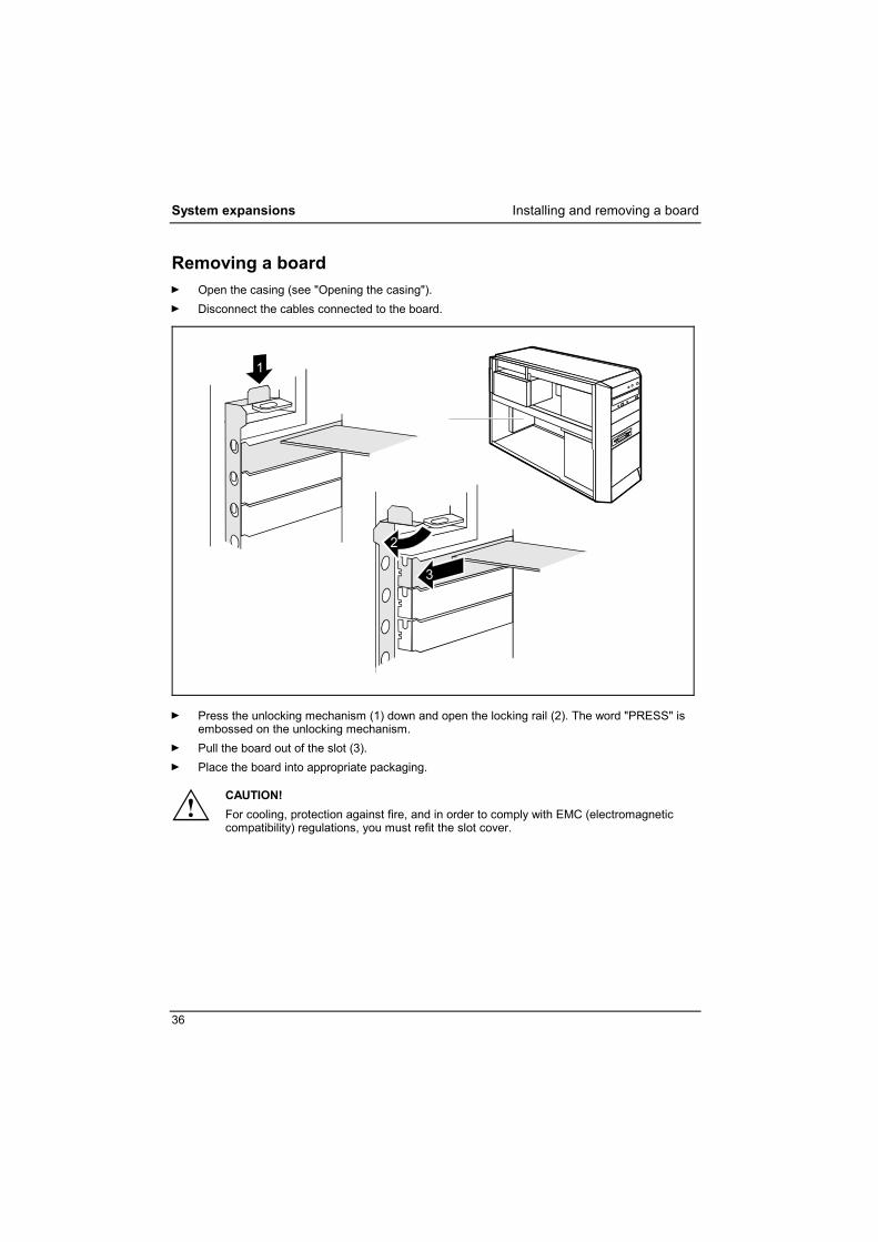
Removing a board Ê Open the casing (see "Opening the casing"). Ê Disconnect the cables connected to the board.
1
2
3
Ê Press the unlocking mechanism (1) down and open the locking rail (2). The word "PRESS" is
embossed on the unlocking mechanism. Ê Pull the board out of the slot (3). Ê Place the board into appropriate packaging.
!
CAUTION! For cooling, protection against fire, and in order to comply with EMC (electromagnetic compatibility) regulations, you must refit the slot cover.
Installing and removing a board System expansions
37
2
1
a
3
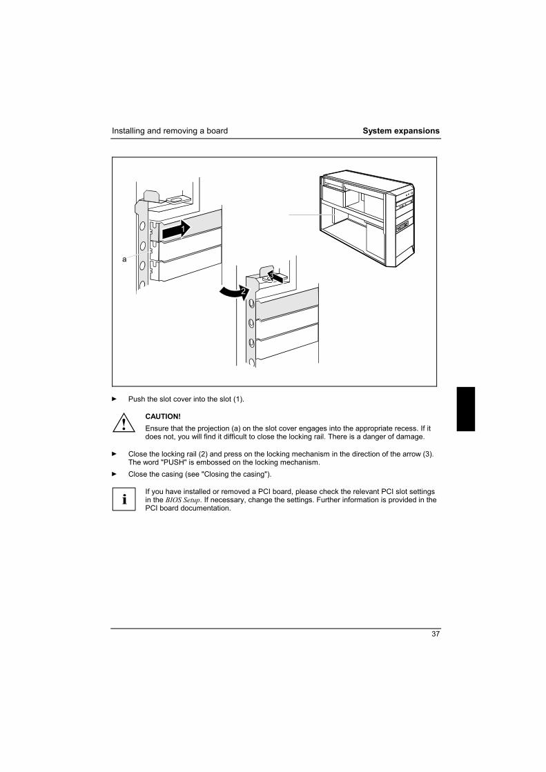
Ê Push the slot cover into the slot (1).
!
CAUTION! Ensure that the projection (a) on the slot cover engages into the appropriate recess. If it does not, you will find it difficult to close the locking rail. There is a danger of damage.
Ê Close the locking rail (2) and press on the locking mechanism in the direction of the arrow (3).
The word "PUSH" is embossed on the locking mechanism. Ê Close the casing (see "Closing the casing").
i
If you have installed or removed a PCI board, please check the relevant PCI slot settings in the BIOS Setup. If necessary, change the settings. Further information is provided in the PCI board documentation.

System expansions Low-Profile boards
38
Low-Profile boards For units with a particularly low overall height, there are so-called low-profile boards with a slot cover with a lower overall height to match the low-profile units. To also install these low-profile boards in normal board slots, you must mount a corresponding slot adapter beforehand Two-piece rear covers are fitted into the slots intended for low-profile boards. The two pieces are connected together with a screw. Ê Remove the desired rear cover and then remove the screw.
Mounting slot adapter
2
1
Ê Fit the slot adapter on the slot cover of the low-profile board (1) and screw it on (2).
Now you can install the low-profile board in a suitable slot like a normal board (see the chapter "Installing board").
Removing slot adapter
2
1
Ê Unscrew the screw (1) and remove the slot adapter (2).
Low-Profile boards System expansions
39
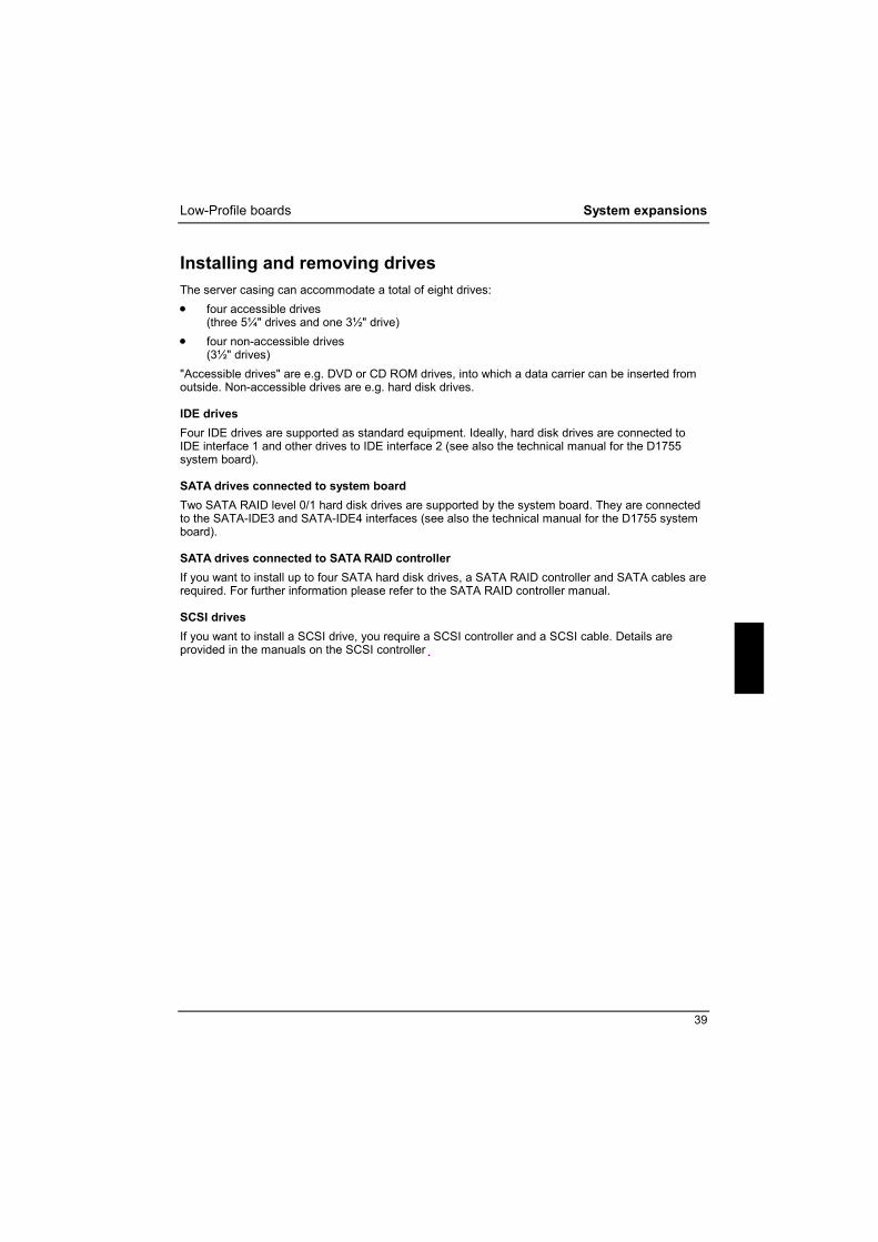
Installing and removing drives The server casing can accommodate a total of eight drives: • four accessible drives
(three 5¼" drives and one 3½" drive) • four non-accessible drives
(3½" drives) "Accessible drives" are e.g. DVD or CD ROM drives, into which a data carrier can be inserted from outside. Non-accessible drives are e.g. hard disk drives.
IDE drives Four IDE drives are supported as standard equipment. Ideally, hard disk drives are connected to IDE interface 1 and other drives to IDE interface 2 (see also the technical manual for the D1755 system board).
SATA drives connected to system board Two SATA RAID level 0/1 hard disk drives are supported by the system board. They are connected to the SATA-IDE3 and SATA-IDE4 interfaces (see also the technical manual for the D1755 system board).
SATA drives connected to SATA RAID controller If you want to install up to four SATA hard disk drives, a SATA RAID controller and SATA cables are required. For further information please refer to the SATA RAID controller manual.
SCSI drives If you want to install a SCSI drive, you require a SCSI controller and a SCSI cable. Details are provided in the manuals on the SCSI controller.

System expansions Low-Profile boards
40
Removing the front panel Ê Open the casing (see "Opening the casing"). Ê Detach the unlocking lever (1) and open the front panel (2).
2
1
1
Ê Detach the plastic hook on the front panel of the casing and carefully remove the front panel. If
you pull too hard, you may loosen or damage the LCD cable.

Low-Profile boards System expansions
41
Attaching the front panel Ê Engage the locking mechanism on the right of the casing. Attach the front panel on the casing
such that the plastic hooks engage into the correct recesses. Ê Close the front panel (1) and make sure that the LCD cable is not pinched and that the locking
mechanisms engage noticeably (2).
1
2
2

System expansions Low-Profile boards
42
Installing an accessible drive Ê Open the casing (see "Opening the casing"). Ê Remove the front (see "Removing the front panel").
1
1
Ê Press the EasyChange rails (1) together and pull the empty slide-in module out of the
casing (2).

Low-Profile boards System expansions
43
Ê Pull the EasyChange rails off the empty slide-in module.
i
Do not dispose of the empty slide-in module. For cooling, protection against fire, and in order to comply with EMC regulations, you must refit the empty slide-in module if you remove the drive again later.
Ê Take the new drive out of its packaging. Ê Adjust the required settings on the drive (if necessary, on already-installed drives as well).
Ê Press the EasyChange rails into the provided holes.
Ê Push the accessible drive into the casing until the EasyChange rails engage. Ê Plug the data and the power supply connectors into the drive. Make sure the polarity is correct.
System expansions Low-Profile boards
44
Ê Attach the front panel (see "Attaching the front panel"). Ê Close the casing (see "Closing the casing").
i
With the upper three accessible drives, the EasyChange rail is attached at the bottom of the module. The rail is attached at the center of the module on the lowest drive. All rails are mounted correctly on delivery. It may be necessary to modify the entry for the drive in the BIOS Setup.
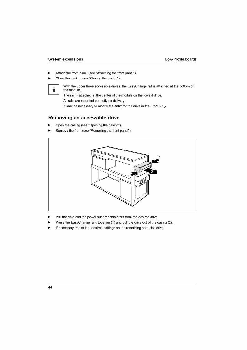
Removing an accessible drive Ê Open the casing (see "Opening the casing"). Ê Remove the front (see "Removing the front panel").
1
1
Ê Pull the data and the power supply connectors from the desired drive. Ê Press the EasyChange rails together (1) and pull the drive out of the casing (2). Ê If necessary, make the required settings on the remaining hard disk drive.

Low-Profile boards System expansions
45
Ê Pull the EasyChange rails off the drive.
Ê Press the EasyChange rails into the holes provided in the empty slide-in module.
System expansions Low-Profile boards
46
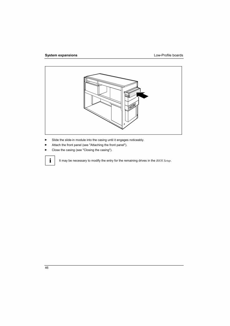
Ê Slide the slide-in module into the casing until it engages noticeably. Ê Attach the front panel (see "Attaching the front panel"). Ê Close the casing (see "Closing the casing").
i
It may be necessary to modify the entry for the remaining drives in the BIOS Setup.

Low-Profile boards System expansions
47
Changing the floppy disk drive Ê Open the casing (see "Opening the casing"). Ê Remove the front (see "Removing the front panel"). Ê Disconnect the cables connected to the floppy disk drive.
Removing the floppy disk drive
1
1
Ê Press the EasyChange rails in the direction of the arrows (1). Ê Pull the floppy disk drive slide-in module out of the casing (2).
Ê Pull the EasyChange rails off the floppy disk drive slide-in module.

System expansions Low-Profile boards
48
1
1
Ê Remove the screws (1) on both sides of the slide-in module. Ê Pull the floppy disk drive out of the slide-in module (2).
Installing the floppy disk drive Ê Take the new floppy disk drive out of its packaging.
2
2
Ê Slide the floppy disk drive into the slide-in module (1). Ê Fasten the floppy disk drive with the screws (2) on both sides of the slide-in module.

Low-Profile boards System expansions
49
Ê Press the EasyChange rails into the provided holes.
Ê Slide the floppy disk drive slide-in module into the casing (1) until it engages noticeably. Ê Fit the data and power supply connectors to the floppy disk drive. Ê Attach the front panel (see "Attaching the front panel"). Ê Close the casing (see "Closing the casing").
i
It may be necessary to modify the entry for the drive in the BIOS Setup.
System expansions Low-Profile boards
50
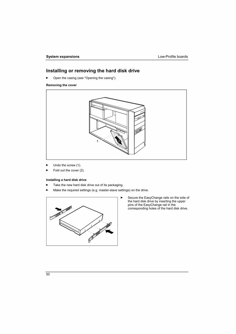
Installing or removing the hard disk drive Ê Open the casing (see "Opening the casing").
Removing the cover
1 2
Ê Undo the screw (1). Ê Fold out the cover (2).
Installing a hard disk drive Ê Take the new hard disk drive out of its packaging. Ê Make the required settings (e.g. master-slave settings) on the drive.
Ê Secure the EasyChange rails on the side of the hard disk drive by inserting the upper pins of the EasyChange rail in the corresponding holes of the hard disk drive.
Low-Profile boards System expansions
51
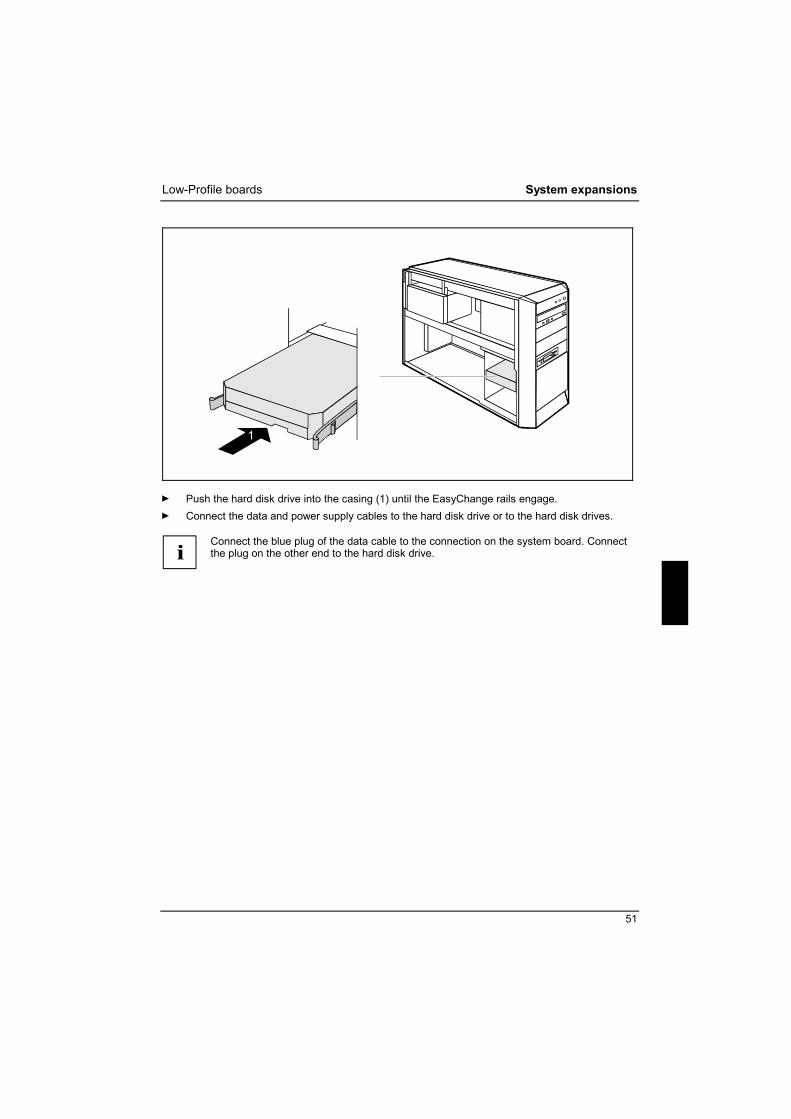
1
Ê Push the hard disk drive into the casing (1) until the EasyChange rails engage. Ê Connect the data and power supply cables to the hard disk drive or to the hard disk drives.
i
Connect the blue plug of the data cable to the connection on the system board. Connect the plug on the other end to the hard disk drive.

System expansions Low-Profile boards
52
Installing the cover plate
2 1
aa
Ê Set the cover plate into the casing such that the projections (a) engage into the appropriate
recesses (1). Ê Close the cover and fasten it with the screw (2). Ê Close the casing (see "Closing the casing").
i
It may be necessary to modify the entry for the drive in the BIOS Setup.

Low-Profile boards System expansions
53
Removing a hard disk drive Ê Open the casing (see "Opening the casing"). Ê Remove the cover (see "Removing the cover"). Ê Disconnect all cables connected to the drive (data cable, power supply cable).
1
1
2
Ê Press the EasyChange rails in the direction of the arrows (1). Ê Take the hard disk drive out of the carrier (2).
Ê Pull the EasyChange rails off the hard disk drive.
If necessary, make the required settings on the remaining hard disk drive.
Ê Install the cover plate (see "Installing the cover plate"). Ê Close the casing (see "Closing the casing").
i
It may be necessary to modify the entry for the drive in the BIOS Setup.
System expansions Extensions to the system board
54
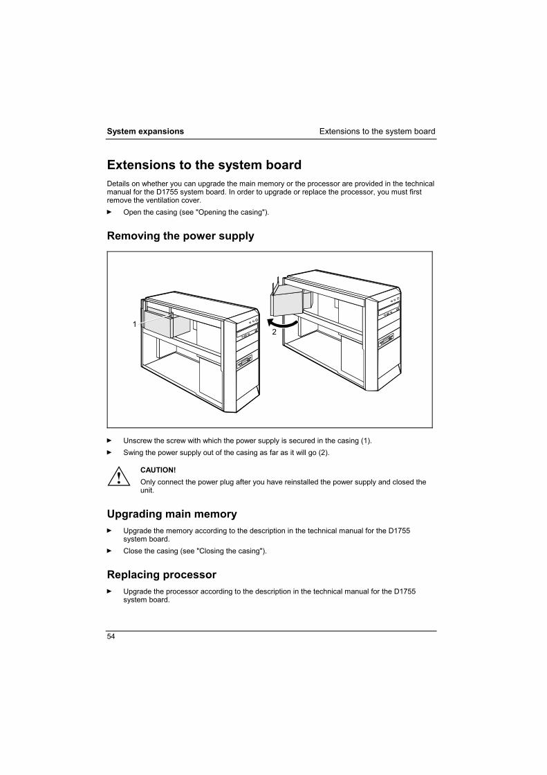
Extensions to the system board Details on whether you can upgrade the main memory or the processor are provided in the technical manual for the D1755 system board. In order to upgrade or replace the processor, you must first remove the ventilation cover. Ê Open the casing (see "Opening the casing").
Removing the power supply
12
Ê Unscrew the screw with which the power supply is secured in the casing (1). Ê Swing the power supply out of the casing as far as it will go (2).
!
CAUTION! Only connect the power plug after you have reinstalled the power supply and closed the unit.
Upgrading main memory Ê Upgrade the memory according to the description in the technical manual for the D1755
system board. Ê Close the casing (see "Closing the casing").
Replacing processor Ê Upgrade the processor according to the description in the technical manual for the D1755
system board.

Extensions to the system board System expansions
55
Replacing lithium battery In order to permanently save the system information, a lithium battery is installed to provide the CMOS-memory with a current. A corresponding error message notifies the user when the charge is too low or the battery is empty. The lithium battery must then be replaced.
!
CAUTION! Incorrect replacement of the lithium battery may lead to a risk of explosion! The lithium battery may be replaced only with an identical battery or with a type recommended by the manufacturer. Do not throw lithium batteries into the household waste. They must be disposed of in accordance with local regulations concerning special waste. Make sure that you insert the battery the right way round. The plus pole must be on the top!
2 3
Ê Press the locking lug in the direction of the arrow; the battery jumps somewhat out of the
holder (1). Ê Remove the battery (2). Ê Push the new lithium battery of the identical type into the holder (3) and press it downward until
it engages (4).
Swinging the power supply in Ê Swing the power supply into the casing until it meets the stop. Ê Fasten the power supply in the casing with the screw.


57
Technical data Electrical data Regulations complied with: IEC 60950 / EN 60950 UL 1950
CSA 22.2 No.950 Protection class: I Rated power: 270 W Apparent power: 357 VA Thermal dissipation: 1200 kJ/h Rated voltage range (automatic, 300 W power supply):
100 V - 240 V
Rated frequency: 50 Hz - 60 Hz Rated current: • Basic configuration: • Max. configuration:
100 V - 240 V / 2,2 - 1,0 A 100 V - 240 V / 7,5 - 3,5 A
Monitor socket (output): 100 V / 3,0 A 240 V / 1,5 A
Dimensions Width/depth/height: 205 mm/505 mm/385 mm
Weight depending on configuration: approx. 15 to 22 kg
Environmental conditions Environment class (3K2) Environment class (2K2)
DIN IEC 721 part 3-3 DIN IEC 721 part 3-2
Temperature: • Operating (3K2) • Transport (2K2)
15 °C .... 35 °C -25 °C .... 60 °C
Condensation in operating must be avoided. Clearance required to ensure adequate ventilation: • front • rear • left • right
min. 200 mm min. 200 mm min. 100 mm min. 100 mm
i
The data sheet of the server contains further technical data. You will find the data sheet either on the "ServerStart" CD supplied or on the Internet at: http://www.fujitsu-siemens.com/.


59
Index
3 3 1/2-inch drive 39
5 5 1/4-inch drive 39
A Alt Gr key 22 Anti-theft protection 24
B Battery 55 BIOS Setup 24
security functions 25 system settings 24
Board 31 installing 34 removing 34, 36
C Cables
connecting 14 disconnecting 15
Casing closing 33 lead-sealing 24 locking 33 opening 32
CD-ROM drive indicator 21 installing 42 removing 44
CE certificate 5 Chain 24 Class B Compliance Statement 6 Configuration
BIOS Setup 24 with ServerStart 13 without ServerStart 13
Contents of delivery 7 Control key 22 Ctrl key 22 Ctrl+Alt+Del 22 Cursor keys 21
D Data protection 24 Date, not correct 30 Device drivers
parallel port 16 serial port 16 USB 17
Devices connecting 14, 16, 17 ports 15 with USB port 17
Devices with USB port, software 17 Disposal 5 Drive 39
accessible 39 installing 39, 42 non-accessible drive 39 removing 39, 44
E Electromagnetic compatibility 5 Energy saving 5 Enter key 22 Ergonomics 8 Error
date 30 floppy disk 29 message 30 mouse 29 screen 28 server 27 time 30
ESD 31 Extensions
server 31 system board 54
External devices connecting 14, 16, 17 ports 15
F FCC statement 6 Floppy disk
cannot read 29 cannot write 29 inserting 23 removing 23 write-protection 23, 29 write-protection, disabling 23
Floppy disk drive changing 47 indicator 21 installing 48, 49 removing 47
Floppy disk indicator 21
Index
60
Function keys 21
H Hard disk drive
indicator 20 installing 50, 52 removing 50, 53
Hard disk indicator 20
I IDE drives 39 Installation
switching on for the first time 11 Installing, software 11, 13 Interfaces 15
K Kensington Lock 24 Key
Alt Gr 22 Control key 22 Ctrl 22 Ctrl key 22 Ctrl+Alt+Del 22 Enter key 22 Menu key 22 Num Lock 22 Return key 22 Shift 22 Shift key 22 Start key 22
Key combination 22 Keyboard 21
connecting 9 important keys 22 port 9, 15
Keypad, alphanumeric 21
L LAN port 15 Lead-sealing 24 Lithium battery 54
replacing 55 Low-profile boards 38
mounting slot adapter 38 removing slot adapter 38
M Main memory 54
upgrading 54 Main switch 12 Manuals, further 30 Memory
insufficient 30 not enough 30
Menu key 22 Monitor
cleaning 6 connecting 8 remains blank 28 switching on 11 transporting 6
Monitor screen, no screen display 28 Mouse
connecting 9 error 29 pointer 29 port 15
N New installation, software 27 New software, installing 27 Notational conventions 3 Note
boards 31 CE certificate 5 important 5
Num Lock key 22 Numeric keypad 21
O ON/OFF button 12, 22 Operating system
installing 13
P Packing material 7
unpacking 7 Parallel port 15
connecting devices 16 settings 16
PCI SATA RAID controller configuring 13
PCI SCSI controller configuring 13
Port keyboard 15 LAN 15 monitor 15 mouse 15 parallel port 15 printer 15 PS/2 mouse 15 SCSI 15 serial port 15 USB 15
Power supply, removing 54
Index
61
Power-on indicator 12, 20 dark 27 fails to light 20, 27 lights green 20 lights orange 20
Preparing for first use, overview 7 Preparing for use 7
overview 7 Printer 15 Processor 54 Product features 2 Property protection 24 Protection, property and data 24 PS/2 mouse
connecting 9 port 9, 15
R Ready-to-operate 12 Recycling 5 Retransportation 6 Return key 22
S Safety 5 SATA drives
connected to SATA RAID controller 39 connected to system board 39
SATA RAID controller configuring 13
SCSI drives 39 SCSI port 15 Security functions, BIOS Setup 25 Serial port 16
connecting devices 16 port 15 settings 16
Server anti-theft protection 24 cabling 14 cannot boot 27 checking rated voltage 10 cleaning 6 closing 33 configuring 13 connecting 10 connecting devices 14 extensions 31 indicator 20 lead-sealing 24 locking 33 opening 32 ports 15 ready for operation 19
setting up 8 soft power off 19 switching off 19 switching off, with main switch 19 switching on 11, 19 switching on, with main switch 19 transporting 6
Setup, see BIOS Setup Shift key 22 Signs and symbols 3 Soft power off 19 Software
installing 11, 13 new installation 27
Standard keyboard, connecting 9 Start key 22 Streamer
installing 42 removing 44
Summer time 30 System board, extensions 54 System expansion 31 System settings, BIOS Setup 24
T Target group 3 Technical data 57 Time
daylight savings 30 not correct 30
Tips 27, 30 Transport 6 Trouble
floppy disk 29 mouse 29 screen 28 server 27
Troubleshooting 27
U USB keyboard port 9 USB keyboard, connecting 9 USB mouse port 9 USB mouse, connecting 9 USB port 15, 17
connecting devices 17
V Ventilation area 8 Video workstation 8
W Warm boot 22 Write protection, floppy disk 23, 29

62
Information on this document On April 1, 2009, Fujitsu became the sole owner of Fujitsu Siemens Compu-ters. This new subsidiary of Fujitsu has been renamed Fujitsu Technology So-lutions.
This document from the document archive refers to a product version which was released a considerable time ago or which is no longer marketed.
Please note that all company references and copyrights in this document have been legally transferred to Fujitsu Technology Solutions.
Contact and support addresses will now be offered by Fujitsu Technology So-lutions and have the format …@ts.fujitsu.com.
The Internet pages of Fujitsu Technology Solutions are available at http://ts.fujitsu.com/... and the user documentation at http://manuals.ts.fujitsu.com.
Copyright Fujitsu Technology Solutions, 2009
Hinweise zum vorliegenden Dokument Zum 1. April 2009 ist Fujitsu Siemens Computers in den alleinigen Besitz von Fujitsu übergegangen. Diese neue Tochtergesellschaft von Fujitsu trägt seit-dem den Namen Fujitsu Technology Solutions.
Das vorliegende Dokument aus dem Dokumentenarchiv bezieht sich auf eine bereits vor längerer Zeit freigegebene oder nicht mehr im Vertrieb befindliche Produktversion.
Bitte beachten Sie, dass alle Firmenbezüge und Copyrights im vorliegenden Dokument rechtlich auf Fujitsu Technology Solutions übergegangen sind.
Kontakt- und Supportadressen werden nun von Fujitsu Technology Solutions angeboten und haben die Form …@ts.fujitsu.com.
Die Internetseiten von Fujitsu Technology Solutions finden Sie unter http://de.ts.fujitsu.com/..., und unter http://manuals.ts.fujitsu.com finden Sie die Benutzerdokumentation.
Copyright Fujitsu Technology Solutions, 2009