ypp6400 - yokogawa electric · 2 ypp6400 proplus high voltage & current meter easy-to-use the...
TRANSCRIPT

• (1)HighVoltageand(1)HighCurrentInput• MultiplicationforApparentPowerCalculation• 0-300VACorVDCVoltageInput• 0-5AACorADCCurrentInput• NEMA4X,IP65Front• InputPowerOptionsInclude85-265VACor12/24VDC• LargeDual-Line6-DigitDisplay,0.60"&0.46"• SunlightReadableDisplayModels• ProgrammableDisplay&FunctionKeys• 2or4Relays+Isolated4-20mAOutputOptions• External4-Relay&DigitalI/OExpansionModules• USB,RS-232,&RS-485SerialCommunicationOptions• Modbus®RTUCommunicationProtocolStandard• Configure,Monitor,andDatalogfromaPCwith
FreePROPLUSSoftware
HIgHVOLTAgE&CURRENT
YPP6400PROPLUSHighVoltage&CurrentMeter
www.yokogawa-usa.com

2
YPP6400PROPLUSHighVoltage&CurrentMeter
Easy-to-UseThe user friendly dual-line display makes the PROPLUS easy to set up & program. No jumpers to set for input selection. All setup & programming are done via the front panel. Three levels of password protection help maintain the reliability of the programming.
FunctionKeysThere are three function keys available to the user. These keys can be programmed to trigger certain events (i.e. acknowledge alarms, reset max and/or min, disable/enable output relays, or hold current relay states), provide direct menu access points, and more.
Rugged&DurableA unique front panel design makes the PROPLUS nearly impenetrable in typical applications. Here, the PROPLUS easily survives a direct hit on the display from a heavy 2" solid stainless steel ball dropped from a height of eight feet.
OptionalSunBrightDisplayModelsPROPLUS’s SunBright display models have an extraordinarily bright LED display. They are perfect for applications where the meter is in direct sunlight or in applications where visibility may be impaired by smoke, fog, dust, or distance. Option is available on all PROPLUS models.
Dual-Line6-Character
Display
Large 0.6" Digits
Rugged Front
User ConfigurableLower Display
(Showing Current)
User ConfigurableUpper Display (Showing Voltage)
Programmable Function Keys
Alarm Status Indicators
UV ResistantSunlight Readable
Front Panel NEMA 4X Rated
YPP6400
INTRODUCTIONThe PROPLUS® YPP6400 is a multipurpose, easy to use high voltage and current input meter ideal for measuring direct voltage and current or the output from voltage shunts and current transformers. It has one 0-300 VAC or VDC voltage input and one 0-5 AAC or ADC current input. The meter may be used with a single voltage or current input, or to measure both simultaneously. A math channel P calculates apparent power as the product of the voltage and current inputs.
The YPP6400 can display voltage, current, and apparent power. The dual line display can show any two parameters simultaneously, or alternate between any parameters as well as their programmable units and tags.
A fully loaded YPP6400 meter has the following: four SPDT relays, 4-20 mA output, and a 24 VDC power supply. The YPP6400 capabilities may be enhanced by adding the following external expansion modules: four SPST relays; creating an eight-relay meter, two digital I/O modules with four inputs and four outputs each, serial communication adapters for use with PROPLUS or Modbus RTU, and a dual 4-20 mA expansion module; for a total of three 4-20 mA analog outputs.
KEYFEATURESPrecise,Accurate,andMoreInformativePROPLUS’s large 0.6" upper display provides a highly accurate and precise view of the high voltage/high current measurement, while the lower display can also provide a clearly identifiable custom tag. Its 24-bit A/D is accurate to ±0.03% of calibrated span ±1 count. The YPP6400’s display also has lead zero blanking capability.
ConfigurableThe upper display can be programmed to indicate PV, maximum (peak), minimum (valley), alternating maximum/minimum, one of eight alarm set points, or Modbus input. The lower display can also be configured to display engineering units, set points, user defined legends, or simply turned off.
FREE Programming Software!
3
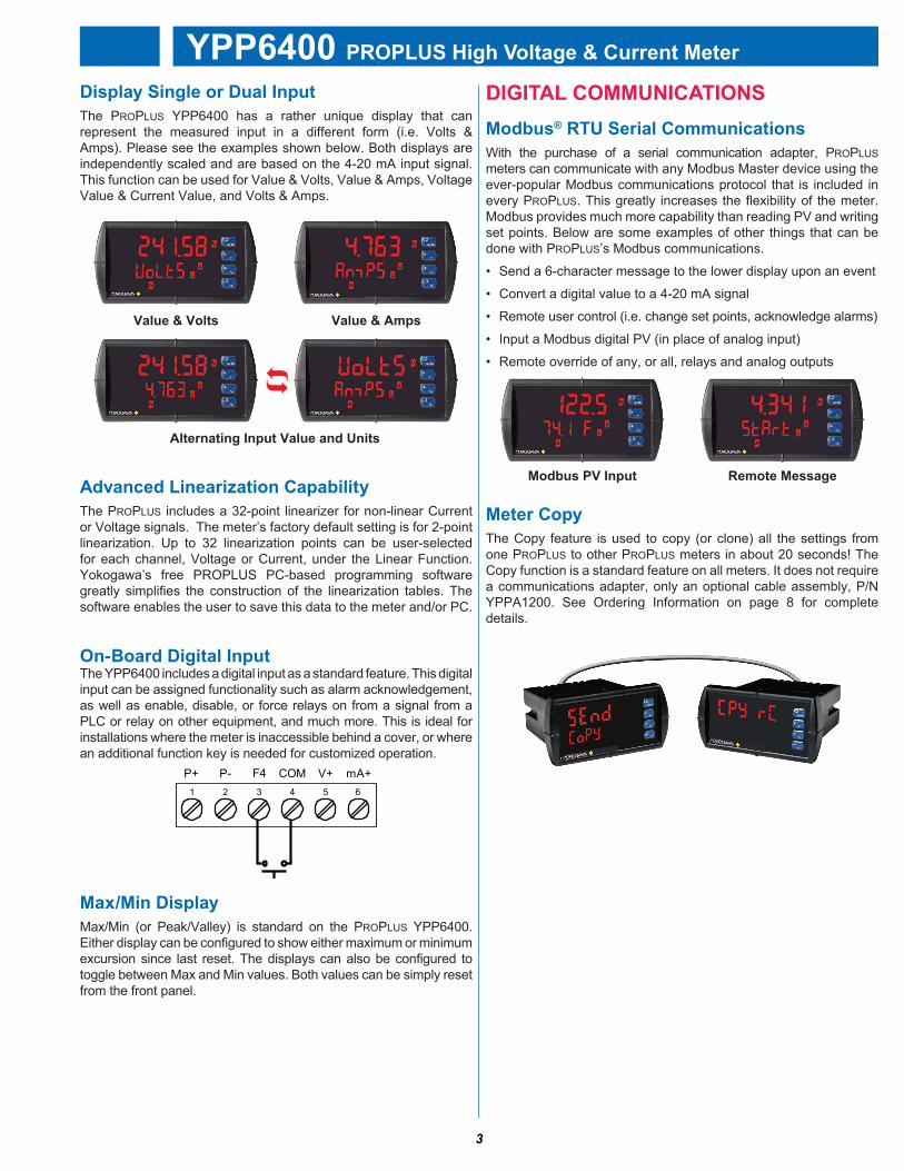
YPP6400PROPLUSHighVoltage&CurrentMeterDIgITALCOMMUNICATIONSModbus®RTUSerialCommunicationsWith the purchase of a serial communication adapter, PROPLUS meters can communicate with any Modbus Master device using the ever-popular Modbus communications protocol that is included in every PROPLUS. This greatly increases the flexibility of the meter. Modbus provides much more capability than reading PV and writing set points. Below are some examples of other things that can be done with PROPLUS’s Modbus communications.
• Send a 6-character message to the lower display upon an event
• Convert a digital value to a 4-20 mA signal
• Remote user control (i.e. change set points, acknowledge alarms)
• Input a Modbus digital PV (in place of analog input)
• Remote override of any, or all, relays and analog outputs
DisplaySingleorDualInputThe PROPLUS YPP6400 has a rather unique display that can represent the measured input in a different form (i.e. Volts & Amps). Please see the examples shown below. Both displays are independently scaled and are based on the 4-20 mA input signal. This function can be used for Value & Volts, Value & Amps, Voltage Value & Current Value, and Volts & Amps.
MeterCopyThe Copy feature is used to copy (or clone) all the settings from one PROPLUS to other PROPLUS meters in about 20 seconds! The Copy function is a standard feature on all meters. It does not require a communications adapter, only an optional cable assembly, P/N YPPA1200. See Ordering Information on page 8 for complete details.
AdvancedLinearizationCapabilityThe PROPLUS includes a 32-point linearizer for non-linear Current or Voltage signals. The meter’s factory default setting is for 2-point linearization. Up to 32 linearization points can be user-selected for each channel, Voltage or Current, under the Linear Function. Yokogawa’s free PROPLUS PC-based programming software greatly simplifies the construction of the linearization tables. The software enables the user to save this data to the meter and/or PC.
On-BoardDigitalInputThe YPP6400 includes a digital input as a standard feature. This digital input can be assigned functionality such as alarm acknowledgement, as well as enable, disable, or force relays on from a signal from a PLC or relay on other equipment, and much more. This is ideal for installations where the meter is inaccessible behind a cover, or where an additional function key is needed for customized operation.
P- COMP+ V+ mA+3 41 2 5
F46
Max/MinDisplayMax/Min (or Peak/Valley) is standard on the PROPLUS YPP6400. Either display can be configured to show either maximum or minimum excursion since last reset. The displays can also be configured to toggle between Max and Min values. Both values can be simply reset from the front panel.
Value&AmpsValue&Volts
AlternatingInputValueandUnits
RemoteMessageModbusPVInput

4
YPP6400PROPLUSHighVoltage&CurrentMeter
YPPA1232,YPPA1485,&YPPA8008CommunicationModulesSerial communications on the PROPLUS can be added anytime with external YPPA1232 (RS-232), YPPA1485 (RS-485), or YPPA8008 (USB) communication adapters.
Free Modbus protocol with the purchase of PROPLUS serial communications modules.
FIELDEXPANSIONMODULESAdd functionality to the PROPLUS in the field with easy-to-install external expansion modules. Add USB, RS-232, or RS-485 communications, I/O modules (up to 2), and 4-relay expansion module. The menu items for these modules do not appear until the module is connected, simplifying the basic menu. Relay and digital I/O modules are shown below with optional DIN rail mounting kit, P/N YPPA1002.
YPPA1044I/OExpansionModuleFour digital inputs and four digital outputs are available per expansion module. The PROPLUS meter will accept two of these modules. External digital inputs can function similarly to the front panel function keys or on-board digital input F4. They can be configured to trigger certain events (i.e. acknowledge/reset alarms, reset max and/or min values, disable/enable all output relays, and hold current relay states), provide direct menu access point, or mimic front panel keys. The I/O module can be used to configure the PROPLUS remotely, in essence giving the user control of the four front panel push buttons. This feature is particularly useful if the meter is mounted inside an explosion-proof enclosure.
Digital outputs can be used to remotely monitor PROPLUS’s alarm relay output states, or the states of a variety of actions and functions executed by the meter.
YPPA1004RelayExpansionModuleAn external module containing four 3 A Form A (SPST) relays can be added to the PROPLUS at anytime. Removable screw terminal blocks accept 12 to 22 AWG wire.
PROPLUSSOFTwAREConfigure, monitor, and datalog a PROPLUS YPP6400 from a PC using PROPLUS Software (available for download at www.yokogawa-usa.com) and a serial adapter.
Mon
itor &
Dat
alog
Line
ariz
atio
n Fe
atur
eS
etup
Rel
ays
YPPA1011DualIsolated4-20mAExpansionModuleAdd analog output to the PROPLUS YPP6400 at any time with dual isolated analog output expansion module YPPA1011.
Connect the expansion module to the meter using the M-Link Connector on the YPP6400. Use only cables provided by Yokogawa in order to protect both the meter and the equipment.

5
YPP6400PROPLUSHighVoltage&CurrentMeterOUTPUTSRelayOutputsThe PROPLUS has up to four 3 A Form C relays (SPDT) with multiple power loss fail-safe options. Relays can be configured for proper protective action upon input loop break. Relay ON and OFF delay times are user adjustable. Up to eight front panel indicators show alarm and/or relay state. All relays can be configured for 0-100% deadband.
RelayOperation/ConfigurationThere are powerful relay functions that can be configured in the PROPLUS meter, including:
• Automatic reset only (non-latching)• Automatic + manual reset at any time (non-latching)• Latching (manual reset only)• Latching with clear (manual reset only after alarm condition has cleared)• Pump alternation control (automatic reset only) • Sampling (activated for a user-specified time)• User selectable fail-safe operation• Relay action for loss (break) of 4-20 mA input signal• Time delay (on and off), independent for each relay• Manual control mode• Interlock relay mode
AnalogOutputThe isolated analog retransmission signal can be configured to represent the process variable (PV), maximum (peak) value, minimum (valley) value, the value for any of the eight relay set points, or Modbus input. While the output is nominally 4-20 mA, the signal will accurately accommodate under- and over-ranges from 1 to 23 mA.
ManualOutputControlTake control of any output with this feature. All relays can be forced ON or OFF, and the 4-20 mA output signal can be set to any value within its range. When the relays and 4-20 mA output are controlled manually, an LED labeled “M” is turned on and the associated Alarm LEDs (1-8) flash every 10 seconds indicating that the meter is in manual control mode.
IsolatedTransmitterPowerSuppliesA powerful 24 V @ 200 mA power supply is a standard feature on the PROPLUS meter. It can be configured for 5, 10, or 24 V (default) by means of a simple internal jumper (see manual). An additional power supply (24 V @ 40 mA) is standard with the 4-20 mA output option.
InterlockRelay(s)This function allows a process to use one or more very low voltage input signals or simple switch contacts to control the state of one or more internal “interlock” relays. A violation (i.e. loss of input, open switch, or open circuit) forces one or more N/O interlock relay contacts to open. One input can be used in series with a number of interlock switches, or up to eight inputs can be required to force-on one (or more) internal interlock relays. Please see Application Note AN-1008 on our website for more information. Requires YPPA1044 Digital I/O module or use of on-board digital input F4.
InterlockRelayConnections
APPLICATIONEXAMPLESThe YPP6400 PROPLUS can be used to display application data for voltage, current, or both. Each Channel, Voltage or Current, can be scaled independently. The following examples show just a few of the YPP6400’s application capabilities using generators and transformers. Each example is followed by a wiring diagram that shows proper switch position for the meter.
VoltageInputApplicationExample
COMNO NC
4 36 5 2 1
+5V I1
1 2
115 VAC
NEUTLOAD
COMNO NC
InterlockContact
(Digital Input) ControlRelay
InterlockRelay
Generator (120 VAC)
Load
+
≈120 VAC
–
VoltageInputwiringExamplewithACSwitchSelected
ModelPD6400HighVoltage&CurrentMeter InstructionManual
19
PowerConnectionsPower connections are made to a two-terminal connector labeled POWER on Figure 6. The meter will operate regardless of DC polarity connection. The + and - symbols are only a suggested wiring convention.
Figure7.PowerConnectionsSignalConnections
Signal connections are made to a four-terminal connector labeled SIGNAL on Figure 6. The I+ and I- terminals are used for Channel A (CH-A) as the current input terminals. The V+ and V- terminals are used for Channel V (CH-V) as the voltage input terminals.In addition to the signal connections, the switch labeled TYPE on Figure 6 must be set to AC (alternating current) or DC (direct current) to accept the corresponding type of voltage and current signals.
VoltageInputThe following figures show examples of connecting the meter for a voltage input. Note that in addition to the connections, the AC/DC type switch much also be set.
Figure8.ACVoltageInput Connection
AC or DCPOWER
Required External Fuse:5 A max, 250 V Slow Blow
POWER+ -
VoltageMeasurementforageneratorDrivingaLoad
6
YPP6400PROPLUSHighVoltage&CurrentMeter
YPPA2811Plastic Low-Cost
CONNECTIONS
RI- I+
MA OUT13 2
POWER
+ -SIGNAL
M-LINK
C NONO NC NC C
RELAY4 RELAY34 36 5 2 1
C NONO NC NC C
RELAY2 RELAY14 36 5 2 1
1 2 3 4 5 6 7 8
21
+
4-20 mA Output
-+
Powered by PROVU
24 V
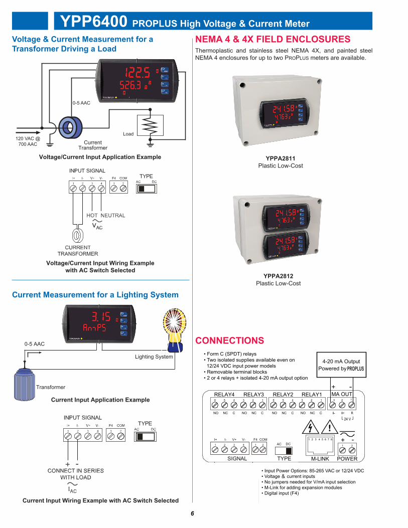
• Form C (SPDT) relays• Two isolated supplies available even on 12/24 VDC input power models • Removable terminal blocks• 2 or 4 relays + isolated 4-20 mA output option
• Input Power Options: 85-265 VAC or 12/24 VDC • Voltage or current inputs• No jumpers needed for V/mA input selection• M-Link for adding expansion modules• Digital input (F4)
PROVU provides 24V@200 mA to
power the transmitter
-
P- COMP+ V+ mA+3 41 2 5
F46
NEMA4&4XFIELDENCLOSURESThermoplastic and stainless steel NEMA 4X, and painted steel NEMA 4 enclosures for up to two PROPLUS meters are available.
YPPA2812Plastic Low-Cost
ModelPD6400HighVoltage&CurrentMeter InstructionManual
18
ConnectionsAll connections are made to removable screw terminal connectors located at the rear of the meter.
Caution!
Use copper wire with 60°C or 60/75°C insulation for all line voltage connections. Observe all safety regulations. Electrical wiring should be performed in accordance with all applicable national, state, and local codes to prevent damage to the meter and ensure personnel safety.
ConnectorsLabelingThe connectors’ label, affixed to the meter, shows the location of all connectors available with requested configuration.
warning!
Do not connect any equipment other than Precision Digital’s expansion modules, cables, or meters to the RJ45 M-LINK connector. Otherwise damage will occur to the equipment and the meter.
Figure6.Connector LabelingforFullyLoadedPD6400
+
M-LINK
1 2 3 4 5 6 7 8
1 2
POWERSIGNAL
V+ V- F4 COM214321
I+ I-AC
TYPE
DC
MA OUT2 1
I- I+ R
3RELAY4 RELAY3
4 36 5 2 1RELAY2 RELAY1
4 36 5 2 1
NC CNO NC CNO NC CNO NC CNO
Voltage/CurrentInputApplicationExample
Load120 VAC @
700 AAC
0-5 AAC
Voltage/CurrentInputwiringExamplewithACSwitchSelected
CurrentInputApplicationExample
0-5 AAC
CurrentInputwiringExamplewithACSwitchSelected
ModelPD6400HighVoltage&CurrentMeter InstructionManual
20
Figure9.DCVoltageInput ConnectionsCurrentInput
The following figures show examples of connecting the meter for a current input. Note that in addition to the connections, the AC/DC type switch much also be set.
Figure10.ACCurrentConnections
Figure11.ACCurrentTransformerConnections
Transformer
Lighting System
ModelPD6400HighVoltage&CurrentMeter InstructionManual
22
Figure14.ACCurrentTransformerandVoltageConnections
Figure15.DCCurrentandVoltageConnections
CurrentTransformer
&
0-5 AAC
Voltage&CurrentMeasurementforaTransformerDrivingaLoad
CurrentMeasurementforaLightingSystem
PROPLUS

7
YPP6400PROPLUSHighVoltage&CurrentMeterSPECIFICATIONSExcept where noted all specifications apply to operation at +25°C.
generalDisplay: Upper display: 0.60" (15 mm) high. Lower display: 0.46" (12 mm) high. Both are 6 digits (-99999 to 999999), with red LEDs.DisplayIntensity: Eight user-selectable intensity levelsDisplayUpdateRate: 5/second (200 ms)Overrange: Display flashes 999999Underrange: Display flashes -99999DisplayAssignment: The main (Big) and secondary (Little) displays may be assigned to process values for Channels A (Ch-A, current), V (Ch-V, voltage), or P (Ch-P, apparent power); toggle between (Ch-A & Ch-V, Ch-A & Ch-P, Ch-V & Ch-P, and Ch-A, Ch-V, & Ch-P); relay set points; max and/or min values for CH-A, Ch-V, or Ch-P; CH-A and units; Ch-V and units; Ch-P and units; or Modbus input. The lower display may also be set to show engineering units or be set to off, with no display.FrontPanel: NEMA 4X, IP65ProgrammingMethods: Four front panel buttons, digital inputs, PC and PROPLUS software, Modbus registers, or cloning using Copy function.F4DigitalInputContacts: 3.3 VDC on contact. Connect normally open contacts across F4 to COM.F4DigitalInputLogicLevels: Logic High: 3 to 5 VDC Logic Low: 0 to 1.25 VDCNoisefilter: Programmable from 2 to 199 (0 will disable filter)FilterBypass: Programmable from 0.1 to 99.9% of calibrated spanRecalibration: Calibrated at the factory. Recalibration is recommended at least every 12 months.Max/MinDisplay: Max / min readings reached by the process are stored until reset by the user or until power to the meter is cycled.Password: Three programmable passwords restrict modification of programmed settings. Non-VolatileMemory: All programmed settings are stored in non-volatile memory for a minimum of ten years if power is lost.InputPowerOptions: 85-265 VAC 50/60 Hz, 90-265 VDC, 20 W max, or jumper selectable 12/24 VDC ±10%, 15 W max.Fuse: Required external fuse: UL Recognized, 5 A max, slow blow; up to 6 meters may share one 5 A fuse.NormalModeRejection: Greater than 60 dB at 50/60 HzIsolation: 500 V AC/DC potential allowed between voltage and current input channels. Channels isolated by 3 MΩ impedance 500 V input-to-output or output-to-P+ supply.OvervoltageCategory:Installation Overvoltage Category II: Local level with smaller transient overvoltages than Installation Overvoltage Category III.Environmental: Operating temperature range: -40 to 65°C Storage temperature range: -40 to 85°C Relative humidity: 0 to 90% non-condensingConnections: Removable screw terminal blocks accept 16 to 28 AWG wire, RJ45 for external relays, digital I/O, and serial communication adapters.Enclosure: 1/8 DIN, high impact plastic, UL 94V-0, color: blackMounting: 1/8 DIN panel cutout required: 3.622" x 1.772" (92 mm x 45 mm). Two panel mounting bracket assemblies are provided.TighteningTorque: Screw terminal connectors: 5 lb-in (0.56 Nm)Dimensions: 4.68" x 2.45" x 5.64" (119 mm x 62 mm x 143 mm) (W x H x D)weight: 9.5 oz (269 g)ULFileNumber: UL & C-UL Listed. E348677; 508 Industrial Control Equipment.warranty: 3 years parts & labor
VoltageandCurrentInputsHighVoltageInput: One high voltage input (Channel V) 0-300 VDC or VAC; Switch Selectable, Modbus PV (Slave)HighCurrentInput: One high current input (Channel A)0-5 AAC or ADC; Switch Selectable, Modbus PV (Slave)Channels: Channel A, Channel V, Channel P (Math Channel for Apparent Power)
AC/DCSelection: Switch selectable for AC or DC inputs. Channels A and V share AC/DC selection.ApparentPowerMath: Apparent power P calculated as P = ((A * V) + C) * FProgrammableConstants: Constant C (Adder): -99.999 to 999.999, default: 0.000. Constant F (Factor): 0.001 to 999.999, default: 1.000.Accuracy: ADC: 0.03% Full Scale ±1 count,AAC: 0.1% Full Scale ±1 count,VDC: 0.05% Full Scale ±1 count,VAC: 0.15% Full Scale ±1 count, square root & programmable exponent accuracy range: 10-100% of calibrated spanTemperatureDrift: 0.005% of calibrated span/°C max from -40 to 65°C ambientSignalInputConditioning: Linear, square root, programmable exponent, or round horizontal tank volume calculation.Multi-PointLinearization: 2 to 32 points for Channel A and VLow-FlowCutoff: 0-999999 (0 disables cutoff function). Independent for Channel A and V.DecimalPoint: Up to five decimal places or none: d.ddddd, dd.dddd, ddd.ddd, dddd.dd, ddddd.d, or dddddd.CalibrationRange: Input Channel Input Range Minimum Span Input 1 & Input 2A +/- 0-5 ADC/0-5 AAC +/- 0.005 ADC/0.010 AACV +/- 0-300 VDC/0-300 VAC +/- 0.1 VDC/0.3 VACNote: An error message will appear if the input 1 and input 2 signals are too close together.InputImpedance: Voltage Input: greater than 3 MΩ. Current Input: 50 - 100 Ω.InputOverload: Voltage input protected up to 500 VDCCurrent input protected up to 10 A by a 10A/300V fast acting non-resettable fuse. Fuse is NOT resettable after a fault; unit must be factory reconditioned.F4DigitalInputContacts: 3.3 VDC on contact. Connect normally open contacts across F4 to COM.F4DigitalInputLogicLevels: Logic High: 3 to 5 VDC Logic Low: 0 to 1.25 VDC
RelaysRating: 2 or 4 SPDT (Form C) internal and/or 4 SPST (Form A) external;rated 3 A @ 30 VDC and 125/250 VAC resistive load; 1/14 HP (≈ 50 watts)@ 125/250 VAC for inductive loads such as contactors, solenoids, etc.NoiseSuppression: Noise suppression is recommended for each relay contact switching inductive loads.RelayAssignment: Each relay independently assigned to Ch-A, Ch-V, CH-P, or ModbusDeadband: 0-100% of span, user programmableHighorLowAlarm: User may program any alarm for high or low trip point. Unused alarm LEDs and relays may be disabled (turned off).RelayOperation: automatic (non-latching), latching (requires manual acknowledge), sampling (based on time), pump alternation control (2 to 8 relays), Off (disable unused relays and enable interlock feature, manual on/off control mode).RelayReset: User selectable via front panel buttons or digital inputs, or PC.1. Automatic reset only (non-latching), when input passes the reset point. 2. Automatic + manual reset at any time (non-latching).3. Manual reset only, at any time (latching).4. Manual reset only after alarm condition has cleared (latching).Note: Front panel button or digital input may be assigned to acknowledge relays programmed for manual reset.
TimeDelay: 0 to 999.9 seconds, on & off relay time delays. Programmable and independent for each relay.Fail-SafeOperation: Programmable and independent for each relay. Note: Relay coil is energized in non-alarm condition. In case of power failure, relay will go to alarm state.
AutoInitialization: When power is applied to the meter, relays will reflect the state of the input to the meter.BreakConditionOperation: Relay condition when sensor break detected. Programmable independently for each relay as On, Off, or Ignore (maintain last condition).

YPP6400PROPLUSHighVoltage&CurrentMeter
YOKOgAwACORPORATIONOFAMERICA2 DART ROADNEWNAN, GA 30265www.yokogawa-usa.com
Phone: (800) 888-6400Fax: (770) 251-2088
Copyright © 2015LDS6400YK_B 07/15
ORDERINgINFORMATIONPROPLUS®YPP6400•StandardModels
85-265VACModel
12/24VDCModel OptionsInstalled
YPP6400-6R0 YPP6400-7R0 None
YPP6400-6R2 YPP6400-7R2 2 Relays
YPP6400-6R3 YPP6400-7R3 4-20 mA Output
YPP6400-6R4 YPP6400-7R4 4 Relays
YPP6400-6R5 YPP6400-7R5 2 Relays & 4-20 mA Output
YPP6400-6R7 YPP6400-7R7 4 Relays & 4-20 mA Output
Note: 24 V Transmitter power supply standard on all models.
PROPLUS®YPP6400•SunBrightDisplayModels85-265VACModel
12/24VDCModel OptionsInstalled
YPP6400-6H0 YPP6400-7H0 None
YPP6400-6H2 YPP6400-7H2 2 Relays
YPP6400-6H3 YPP6400-7H3 4-20 mA Output
YPP6400-6H4 YPP6400-7H4 4 Relays
YPP6400-6H5 YPP6400-7H5 2 Relays & 4-20 mA Output
YPP6400-6H7 YPP6400-7H7 4 Relays & 4-20 mA Output
Note: 24 V Transmitter power supply standard on all models.
AccessoriesModel Description
YPPA1002 DIN Rail Mounting Kit for Two Expansion Modules
YPPA1004 4-Relay Expansion Module
YPPA1011 Dual Isolated 4-20 mA Expansion Module
YPPA1044 4 Digital Inputs & 4 Digital Outputs Module
YPPA1200 Meter Copy Cable
YPPA1232 RS-232 Serial Adapter
YPPA1485 RS-485 Serial Adapter
YPPA7485-I RS-232 to RS-422/485 Isolated Converter
YPPA7485-N RS-232 to RS-422/485 Non-Isolated Converter
YPPA8008 USB Serial Adapter
YPPA8232-N USB to RS-232 Non-Isolated Converter
YPPA8485-I USB to RS-422/485 Isolated Converter
YPPA8485-N USB to RS-422/485 Non-Isolated Converter
YPPX6901 Suppressor (snubber): 0.01 μF/470 Ω, 250 VAC
DisclaimerThe information contained in this document is subject to change without notice. Yokogawa Corporation of America makes no representations or warranties with respect to the contents hereof, and specifically disclaims any implied warranties of merchantability or fitness for a particular purpose.
©2015 Yokogawa Corporation of America. All rights reserved.
YourLocalDistributoris:
Notes:1. Panel cutout required: 1.772" x 3.622" (45 mm x 92 mm)2. Panel thickness: 0.040 - 0.250" (1.0 mm - 6.4 mm)3. Mounting brackets lock in place for easy mounting4. Clearance: Allow 6" (152 mm) behind the panel
Modbus®RTUSerialCommunicationsMeterAddress/SlaveID: 1 - 247BaudRate: 300 - 19,200 bpsTransmitTimeDelay: Programmable between 0 and 199 msData:8 bit (1 start bit, 1 or 2 stop bits)Parity:Even, odd, or none with 1 or 2 stop bitsByte-to-ByteTimeout:0.01 - 2.54 secondsTurnAroundDelay: Less than 2 ms (fixed)Note: Refer to the PROPLUS® Register Tables for details.
Isolated4-20mATransmitterOutputOutputSource: Process channel A, V, or P, max or min for channel A, V, or highest or lowest max or min of A and V, set points 1-8, Modbus input, or manual control modeScalingRange: 1.000 to 23.000 mA for any display rangeCalibration: Factory calibrated: 4.000 to 20.000 = 4-20 mA outputAnalogOutputProgramming: 23.000 mA maximum for all parameters: Overrange, underrange, max, min, and breakAccuracy: ± 0.1% of span ± 0.004 mATemperatureDrift: 0.4 μA/°C max from 0 to 65°C ambient, 0.8 μA/°C max from -40 to 0°C ambient Note: Analog output drift is separate from input drift.IsolatedTransmitterPowerSupply: Terminals I+ & R: 24 VDC ± 10%. May be used to power the 4-20 mA output or other devices. All models rated @ 40 mA max.ExternalLoopPowerSupply: 35 VDC maximumOutputLoopResistance: Power supply Minimum Maximum 24 VDC 10 Ω 700 Ω 35 VDC (external) 100 Ω 1200 Ω
DIMENSIONS
3.61"(91.5 mm)
4.17"(106 mm)
4.68"(119 mm)
1.76"(44.5 mm)
0.59"(15 mm)
4.77"(121 mm)
2.45"(62 mm)
(128 mm)5.05"
Side View Top View
6" (152 mm) Clearance
NO NCNCC NOCNO NCNCC NOC+ -R
OptionalConnectorsInstalled
3.61"(91.5 mm)
4.17"(106 mm)
4.68"(119 mm)
1.76"(44.5 mm)
0.59"(15 mm)
4.77"(121 mm)
2.45"(62 mm)
(128 mm)5.05"
Side View Top View
6" (152 mm) Clearance
NO NCNCC NOCNO NCNCC NOC+ -R
OptionalConnectorsInstalled