yrc1000 options instructions - motoman robotics...yrc1000 options instructions user’s manual for...
TRANSCRIPT

MANUAL NO.
HW1483600 1
YRC1000 OPTIONSINSTRUCTIONSUser’s Manual For New Language Environment MotoPlus
Upon receipt of the product and prior to initial operation, read these instructions thoroughly, and retain for future reference.
MOTOMAN INSTRUCTIONS
MOTOMAN- INSTRUCTIONSYRC1000 INSTRUCTIONSYRC1000 OPERATOR’S MANUAL (GENERAL) (SUBJECT SPECIFIC)YRC1000 MAINTENANCE MANUAL YRC1000 ALARM CODES (MAJOR ALARMS) (MINOR ALARMS)
1/75
178940-1CD1
HW1483600
DANGER
• This manual explains MotoPlus of the YRC1000 system. Read this manual carefully and be sure to understand its contents before handling the YRC1000. Any matter, including operation, usage, measures, and an item to use, not described in this manual must be regarded as "prohibited" or "improper".
• General information related to safety are described in "Chapter 1. Safety" of the YRC1000 INSTRUCTIONS. To ensure correct and safe operation, carefully read "Chapter 1. Safety" of the YRC1000 INSTRUCTIONS.
CAUTION
• In some drawings in this manual, protective covers or shields are removed to show details. Make sure that all the covers or shields are installed in place before operating this product.
• YASKAWA is not responsible for incidents arising from unauthorized modification of its products. Unauthorized modification voids the product warranty.
NOTICE
• The drawings and photos in this manual are representative examples and differences may exist between them and the delivered product.
• YASKAWA may modify this model without notice when necessary due to product improvements, modifications, or changes in specifications. If such modification is made, the manual number will also be revised.
• If your copy of the manual is damaged or lost, contact a YASKAWA representative to order a new copy. The representatives are listed on the back cover. Be sure to tell the representative the manual number listed on the front cover.
ii HW1483600 2/75

HW1483600
NOTES FOR SAFE OPERATIONRead this manual carefully before installation, operation, maintenance, or inspection of the YRC1000.
In this manual, the Notes for Safe Operation are classified as “DANGER”, “WARNING”, “CAUTION”, or “NOTICE”.
Even items described as “CAUTION” may result in a serious accident in some situations. At any rate, be sure to follow these important items.
DANGERIndicates an imminently hazardous situation which, if not avoided, will result in death or serious injury. Safety Signs identified by the signal word DANGER should be used sparingly and only for those situations presenting the most serious hazards.
WARNINGIndicates a potentially hazardous situation which, if not avoided, will result in death or serious injury. Hazards identified by the signal word WARNING present a lesser degree of risk of injury or death than those identified by the signal word DANGER.
CAUTIONIndicates a hazardous situation, which if not avoided, could result in minor or moderate injury. It may also be used without the safety alert symbol as an alternative to “NOTICE”.
NOTICENOTICE is the preferred signal word to address practices not related to personal injury. The safety alert symbol should not be used with this signal word. As an alternative to “NOTICE”, the word “CAUTION” without the safety alert symbol may be used to indicate a message not related to personal injury.
NOTETo ensure safe and efficient operation at all times, be sure to follow all instructions, even if not designated as “DAN-GER”, “WARNING” and “CAUTION".
iii HW1483600 3/75

HW1483600
DANGER
• Before operating the manipulator, make sure the servo power is turned OFF by performing the following operations. When the servo power is turned OFF, the SERVO ON LED on the programming pendant is turned OFF.
– Press the emergency stop buttons on the front door of the YRC1000, on the programming pendant, on the external control device, etc.
– Disconnect the safety plug of the safety fence. (when in the play mode or in the remote mode)
If operation of the manipulator cannot be stopped in an emergency, personal injury and/or equipment damage may result.
Fig. : Emergency Stop Button
• Before releasing the emergency stop, make sure to remove the obstacle or error caused the emergency stop, if any, and then turn the servo power ON.
Failure to observe this instruction may cause unintended movement of the manipulator, which may result in personal injury.
Fig. : Release of Emergency Stop
TURN
• Observe the following precautions when performing a teaching operation within the manipulator's operating range:– Be sure to perform lockout by putting a lockout device on the
safety fence when going into the area enclosed by the safety fence. In addition, the operator of the teaching operation must display the sign that the operation is being performed so that no other person closes the safety fence.
– View the manipulator from the front whenever possible.– Always follow the predetermined operating procedure.– Always keep in mind emergency response measures against the
manipulator’s unexpected movement toward a person.– Ensure a safe place to retreat in case of emergency.
Failure to observe this instruction may cause improper or unintended movement of the manipulator, which may result in personal injury. • Confirm that no person is present in the manipulator's operating
range and that the operator is in a safe location before: – Turning ON the YRC1000 power – Moving the manipulator by using the programming pendant – Running the system in the check mode– Performing automatic operations
Personal injury may result if a person enters the manipulator's operating range during operation. Immediately press an emergency stop button whenever there is a problem. The emergency stop buttons are located on the front panel of the YRC1000 and on the right of the programming pendant.• Read and understand the Explanation of the Warning Labels before
operating the manipulator.
iv HW1483600 4/75

HW1483600
Definition of Terms Used Often in This ManualThe MOTOMAN is the YASKAWA industrial robot product.
The MOTOMAN usually consists of the manipulator, the controller, the programming pendant, and supply cables.
In this manual, the equipment is designated as follows.
WARNING
• Perform the following inspection procedures prior to conducting manipulator teaching. If there is any problem, immediately take necessary steps to solve it, such as maintenance and repair.
– Check for a problem in manipulator movement.
– Check for damage to insulation and sheathing of external wires.
• Always return the programming pendant to the hook on the YRC1000 cabinet after use.
If the programming pendant is left unattended on the manipulator, on a fixture, or on the floor, etc., the Enable Switch may be activated due to surface irregularities of where it is left, and the servo power may be turned ON. In addition, in case the operation of the manipulator starts, the manipulator or the tool may hit the programming pendant left unattended, which may result in personal injury and/or equipment damage.
Equipment Manual Designation
YRC1000 controller YRC1000
YRC1000 programming pendant Programming pendant
Cable between the manipulator and the controller
Manipulator cable
v HW1483600 5/75

HW1483600
Descriptions of the programming pendant keys, buttons, and displays are shown as follows:
Description of the Operation ProcedureIn the explanation of the operation procedure, the expression "Select • • • " means that the cursor is moved to the object item and [SELECT] is pressed, or that the item is directly selected by touching the screen.
Registered TrademarkIn this manual, names of companies, corporations, or products are trademarks, registered trademarks, or brand names for each company or corporation. The indications of (R) and TM are omitted.
Equipment Manual Designation
Programming Pendant
Character Keys /Symbol Keys
The keys which have characters or its symbol printed on them are denoted with [ ]. ex. [ENTER]
Axis Keys /Numeric Keys
[Axis Key] and [Numeric Key] are generic names for the keys for axis operation and number input.
Keys pressed simultaneously
When two keys are to be pressed simultaneously, the keys are shown with a “+” sign between them, ex. [SHIFT]+[COORD]
Displays The menu displayed in the programming pendant is denoted with { }. ex. {JOB}
vi HW1483600 6/75

Contents
HW1483600
1 Outline ............................................................................................................................................ 1-1
1.1 Introduction........................................................................................................................ 1-1
1.2 Features ............................................................................................................................ 1-1
1.3 What MotoPlus Can Do ..................................................................................................... 1-2
1.4 Supported Services ........................................................................................................... 1-3
1.5 Application Program Development Environment ............................................................... 1-5
1.5.1 Development Environment Configuration............................................................. 1-5
1.5.2 Development Environment Component................................................................ 1-6
1.5.3 Application Program Execution Environment ....................................................... 1-7
1.5.4 Development Flow................................................................................................ 1-8
1.6 Notes ................................................................................................................................. 1-9
2 Development Environment Setup ................................................................................................... 2-1
2.1 DVD Contents.................................................................................................................... 2-1
2.2 Installation of Development Environment Software ........................................................... 2-2
2.3 Installation of TELNET Connection Utility.......................................................................... 2-4
3 Creating Application Software......................................................................................................... 3-1
3.1 Rules for Creating Program Source Code......................................................................... 3-1
3.2 Creating MotoPlus Project ................................................................................................. 3-2
3.3 Outline of MotoPlus IDE .................................................................................................... 3-3
3.4 Text Search ....................................................................................................................... 3-4
3.5 MotoPlus Library Files ....................................................................................................... 3-4
3.6 Program Build (Compile/Link)............................................................................................ 3-4
3.7 Changing Build Settings .................................................................................................... 3-5
3.8 How to Use the DX200 Projects on YRC1000................................................................... 3-6
3.8.1 Difference Points of the API ................................................................................. 3-6
4 Valid/Invalid Setting of MotoPlus Function...................................................................................... 4-1
5 Installation and Start-up of Application Program............................................................................. 5-1
5.1 Installation of Application Program in Maintenance Mode................................................. 5-1
5.2 Start-up of Application Program......................................................................................... 5-6
5.3 To Temporarily Prevent MotoPlus Application from Starting ............................................. 5-6
6 User Defined File ............................................................................................................................ 6-1
vii HW1483600 7/75

Contents
HW1483600
6.1 Saving in and Reading from External Memory ..................................................................6-1
6.1.1 Procedure to Save or Read User Defined File .....................................................6-1
6.2 Initialization of User Defined File ....................................................................................... 6-3
6.3 Setting of File Control Task Priority Limit........................................................................... 6-5
6.3.1 Changing File Control Task Priority Limit ............................................................. 6-5
7 Debugging....................................................................................................................................... 7-1
7.1 Debugging Environment ....................................................................................................7-1
7.2 Connecting YRC1000 with PC........................................................................................... 7-2
7.3 Debugging via Telnet Communication ...............................................................................7-4
7.3.1 Operation Procedure ............................................................................................7-4
7.3.2 Example Usage of Printf()..................................................................................... 7-7
7.4 Debugging by User Variables of YRC1000........................................................................ 7-8
8 Development Support Tool .............................................................................................................8-1
8.1 Outline ............................................................................................................................... 8-1
8.1.1 Introduction...........................................................................................................8-1
8.1.2 Overview of Functions .......................................................................................... 8-1
8.2 Using the Support Tool ......................................................................................................8-2
8.2.1 Support for the Functions ..................................................................................... 8-3
8.3 Basic Settings .................................................................................................................... 8-4
8.3.1 Connecting a PC with the YRC1000..................................................................... 8-4
8.3.2 Communication Settings....................................................................................... 8-4
8.3.3 Setting Procedure................................................................................................. 8-4
8.4 Online Download................................................................................................................8-5
8.4.1 System Settings.................................................................................................... 8-5
8.4.2 Inserting the USB Memory in the Controller .........................................................8-5
8.4.3 Operating Procedure ............................................................................................8-6
8.5 Application Property List .................................................................................................... 8-7
8.5.1 Operating Procedure ............................................................................................8-7
8.5.2 Setting Application Information............................................................................. 8-8
8.5.3 Setting Procedures ...............................................................................................8-9
8.6 Port Debug.......................................................................................................................8-10
8.6.1 Measuring Procedures........................................................................................ 8-11
8.6.2 Optional for Measuring .......................................................................................8-12
viii HW1483600 8/75

Contents
HW1483600
8.6.3 Mounting the Application .................................................................................... 8-13
8.6.4 Debug Port APIs................................................................................................. 8-14
8.7 Copy Protection ............................................................................................................... 8-18
8.7.1 Protection Activation (MotoPlusIDE) .................................................................. 8-18
8.7.2 Acquiring the Serial File (MotoPlus Monitor) ...................................................... 8-19
8.7.3 Generating the Protection Key (MotoPlusIDE) ................................................... 8-19
8.7.4 Loading the Protection Key (MotoPlus Monitor) ................................................. 8-20
8.7.5 Useful Functions (MotoPlusIDE) ........................................................................ 8-21
8.7.5.1 Generating and Downloading the Protection Key ................................. 8-21
8.7.5.2 Downloading the Application and the Protection Key Simultaneously ... 8-21
9 Alarm List ........................................................................................................................................ 9-1
ix HW1483600 9/75

1 Outline1.1 Introduction
HW1483600
1 Outline
1.1 Introduction
This function is used to develop customer specific applications that operate on the main CPU board (ACP01 circuit board) of the YRC1000. The function name MotoPlus is an abbreviation of Motoman Professional Programming Language for Superior Use. MotoPlus is a programming IDE (integrated development environment) for professionals, with which the application program developed on the PC using C language runs as a task of the robot controller. Users can develop a variety of application programs on their own without modifying the source codes of the robot controller.
1.2 Features
1. With C language as the system development language and a wealth of standard libraries, users can create customer specific application programs.
2. With the text editor of MotoPlus IDE, users can program off-line.
3. The created application program runs as a task on the main CPU of the robot controller. Thus, no additional hardware is required.
4. The created application program runs as the native code of the CPU. Thus, the execution speed becomes faster.
5. With a variety of included APIs (application program interface) to transmit data from/to the job, the Ethernet communication port, and the RS232C serial communication port, etc., users can easily correct the manipulator position and connect the robot to the external PC or sensors.
NOTETo use the MotoPlus function, set the MotoPlus FUNC. to “USED” in the OPTION FUNCTION of the maintenance mode.
1-1 HW1483600 10/75

1 Outline1.3 What MotoPlus Can Do
HW1483600
1.3 What MotoPlus Can Do
Users can use the C language, a general programming language, and the C language and MotoPlus libraries to develop a customer specific application program in which various types of resources are used, e.g., the Ethernet communication port, the RS232C serial communication port, and the programming pendant of the robot controller. Refer to fig. 1-1 “Available Resources for MotoPlus” .
Fig. 1-1: Available Resources for MotoPlus
Application program examples:
1. Operation to correct the manipulator position by a communication program with a vision sensor or other sensors, and by data from the sensor
2. Data transmission with an external PC via the Ethernet (TCP/IP) communication
3. JOB execution sequence control
PP(Socket
communicationEthernet)
JOB task Application task CIO
SDcard
EthernetRC232C
(ACP01 SD file)
(RJ45)
Vision
Data transmission(File input)
Data transmission(Winsock)
Data transmission Data transmission
PC
Power ON
Panel computer
Load from the SD / start
1-2 HW1483600 11/75

1 Outline1.4 Supported Services
HW1483600
1.4 Supported Services
MotoPlus provides users with a variety of services as follows:
1. Application task control Application task start/stop, data transmission between application programs by the mailbox and semaphore, exclusive control and execution synchronization
2. Robot control Robot control from the application program
3. JOB control Start-stop control of the JOB by the application, data transmission between Jobs by variables (byte, integer, double-precision, floating-point, character string, and position variable), and execution synchronization
4. CIO control I/O between the application program and the CIO, and read/ write of the register
5. Ethernet communication control The Ethernet (TCP/IP) communication from the application, especially using the socket function library included as an API
6. Programming pendant communication Data transmission between the application and the programming pendant application
7. EVENT Event notification to the application at every I/O control cycle and interpolation control cycle of the system
8. RS232C serial communication control RS232C serial communication from the application
9. Sensor controlThe APIs which transfer data to and from a job and change operating conditions such as path correction and speed change, and the instructions which transfer data between a job and MotoPlus application
10. Memory managementThe protected memory management Specific instructions, malloc and mfree, support the data area which the system manages for MotoPlus.
11. General-purpose file controlThe function to access multiple general-purpose files by using the fixed area on CMOS as a drive
12. Existing file controlThe function to access existing files (jobs and condition files, etc. which can be loaded and saved by external memory)
13. Servo controlServo control from the application program
14. User watchdogWatchdog to monitor whether the application operates normally
15. Coordinate conversionCalculation of the manipulator order or inverse kinematics, coordinate conversion, pulse conversion from the feedback pulse to the arithmetic pulse, or linear algebra calculation.
1-3 HW1483600 12/75
1 Outline1.4 Supported Services
HW1483600
16. Development environment
(1) Integrated development environment (MotoPlus IDE) for source file project management, program editor, and compiler and linker
(2) Installation of the MotoPlus application from the SD/USB memory in the programming pendant
(3) Debugging by printf() via Telnet
1-4 HW1483600 13/75

1 Outline1.5 Application Program Development Environment
HW1483600
1.5 Application Program Development Environment
A MotoPlus application program is written in C language on a PC and debugged on the YRC1000 controller. Use the text editor of MotoPlus IDE to write the application program, then compile and link it to create the execution object. This is installed and executed on the YRC1000 to debug.
1.5.1 Development Environment Configuration
Use a PC to develop an application program. The system is configured as shown in fig. 1-2 “Development Environment Configuration” to debug using Telnet. Install the developed application by loading it to the SD of the main CPU (ACP01) using the SD/USB memory in the programming pendant.
Fig. 1-2: Development Environment Configuration
PC (Windows 7 (32bit) /Windows 10)
Ethernet
Main CPU
(SD)
S-
高
選 択
X-S+
X+
L-Y-
L+Y+
U-Z-
U+Z+
7- 7+
R-X-
R+X+
B-Y-
B+Y+
T-Z-
T+Z+
低
高 速
9
6
3
-.
2
5
87
4
1
0
Program development environment Program execution environment
Robot controller
SD/USB memory (Load)
1-5 HW1483600 14/75

1 Outline1.5 Application Program Development Environment
HW1483600
1.5.2 Development Environment Component
No. Device Details Remarks
1 Windows PC CPU: 1GHz or moreMemory: 1 Gbyte or moreHard disk space: 40 Gbyte or moreOS: Windows 7 (32bit)
Windows 10
Prepared by the user
2 Text editor Creates the application source program in C language. MotoPlus IDE editor is recommended. (A commercially-available text editor and Windows Notepad can also be used.)
Prepared by the user
3 Compiler Converts the source program into the machine language of the target CPU. Integrated in MotoPlus IDE, and can be executed from the menu.
Provided by YASKAWA
4 Linker/library Links the C language library provided by GNU with the developed application program to create an executable load module. Integrated in MotoPlus IDE, and can be executed from the menu.
Provided by YASKAWA
5 MotoPlus library API library which provides application program services of the robot controller such as data communication with JOB. Integrated in MotoPlus IDE.
Provided by YASKAWA
6 SD/USB memory SD memory or USB memory to load the developed load module into the controller.
Prepared by the user
7 Ethernet cable Connects the PC with the controller via Ethernet to debug the developed program. CAT5 or greater (cross/straight) cable
Prepared by the user
8 Ethernet hub Connects the PC with the controller. Prepared by the user
9 Installation DVD Installs the above-mentioned software on the Windows PC. Provided by YASKAWA
1-6 HW1483600 15/75

1 Outline1.5 Application Program Development Environment
HW1483600
1.5.3 Application Program Execution Environment
The application program developed in the above-mentioned program development environment is stored in the SD on the main CPU (ACP01) of the robot controller, as shown in fig. 1-3 “Program Execution Environment” .
Fig. 1-3: Program Execution Environment
When the controller power is turned ON, the application program MotoPlusApl stored in the SD on the main CPU (ACP01), is loaded into the memory of the ACP01 circuit board. Then, the application program is started as a task on the real-time operating system controller OS, and executed synchronously with the system program. The application task can start multiple tasks, and can perform data transmission with JOB or I/O, synchronous execution control, and exclusive control, by using the mailbox or semaphore.
(MotoPlusApl.out)
Controller OS
ACP01 circuit board
Application
program
System
JOB
startup
obtain data
Load, startup
Application
program
ACP01 built-in SD memory
MotoPlusApl.out
1-7 HW1483600 16/75

1 Outline1.5 Application Program Development Environment
HW1483600
1.5.4 Development Flow
Fig. 1-4: Program Development Flow
Modify the program
No compile error?
No compile error?
Start the application program.
Debug.
OK?
Development completed.
Load the application program into the robot controller.
Write the source program in C language by using the editor of MotoPlus IDE.
<3.2 Creating MotoPlus Project>Use GNU C compiler providedby YASKAWA (included in MotoPlus IDE).
Link the above-mentioned objectmodules with the C language libraryand the robot library to create theexecution module (e.g. MotoPlusApl.out).
<3.2 Creating MotoPlus Project>Use GNU linker and library.Only static links are supported.ELF (Executable and LinkableFormat) is used as the module. Compiling and linking are done simultaneously by MotoPlus IDE.
<4.1 Installation of ApplicationProgram in Maintenance Mode>Relocatable module withELF object format.
<4.2 Start-up of ApplicationProgram>
1. Starts with turning ON the power.
<5. Debugging>Debug by connecting to SHELL,system software, via TELNET.Use printf() and puts().
By using MotoPlus IDE, compilethe source program (e.g. abc.c) andcreate an application program(e.g. abc.o).
<3.1 Rules for Creating Program Source Code>Use the editor of MotoPlus IDE.Notepad, WordPad, or anothertext editor can also be used.
1-8 HW1483600 17/75
1 Outline1.6 Notes
HW1483600
1.6 Notes
NOTE
• C language memory operationWhen programming in C language, the pointer variable which stores the memory address can be used. If the pointer variable is set incorrectly, the system memory area may be rewritten. If the system memory area is rewritten, critical problems occur, e.g., the software hangs up (the hang-up status is detected by a CPU exception or the watchdog check func-tion, then the servo power turns OFF and the system shuts down), the robot stops its operation due to an alarm, or the programming pendant becomes inoperable. If the system memory operation is incorrect, the applica-tion itself may not operate as it is designed. Thus, by test-ing adequately, the error location can be found. Check the functions of the application software well enough, and make sure that all functions operate as designed.
• Task “mpUsrRoot” which starts when the power is turned ONThe task “mpUsrRoot” has a high priority to start other application tasks and initialize the entire application quickly. Due to its high task priority, if a time-consuming process (100 microseconds or longer) is done in this task, the processing time for the robot control becomes insuffi-cient. Then the system alarm may occur or the program-ming pendant or the HOLD button may freeze. Thus, as the sample program (refer to “Chap.17.3 Task Control Sample Program” in “Programmer’s Manual for New Lan-guage Environment MotoPlus (HW1483598)”, make sure to complete the task “mpUsrRoot” after starting up another application or creating a semaphore.
• Debugging via Telnet
1. After completing debugging, set the Telnet function to INVALID (S2C1119 = 0). This is because the Telnet function consumes the system processing time, and an alarm may occur due to insufficient processing time for robot operation.
2. With the Telnet function, debug only the tasks with normal priority. For debugging the tasks with high priority (the tasks started with the task priority: MP_PRI_IO_CLK_TAKE, MP_PRI_IP_CLK_TAKE, or MP_TIME_CRITICAL, or the task “mpUsrRoot”), use the variables of the YRC1000. This is because, if printf() or puts() is done with a high priority task, the processing time for the robot operation control is consumed, and a system alarm may occur due to insufficient processing time.
3. After completing debugging, make sure to clear the debugging code using printf() or puts() which is described in the source code. This is because the processing time of printf() and puts() influences the system, and an error may occur such as insufficient processing time during robot operation.
4. When using the SHELL debugging function of the controller OS which becomes available by connecting with the YRC1000 via Telnet, a system alarm may occur due to insufficient processing time for robot operation. Do NOT use the SHELL debugging function.
1-9 HW1483600 18/75
2 Development Environment Setup2.1 DVD Contents
HW1483600
2 Development Environment Setup
2.1 DVD Contents
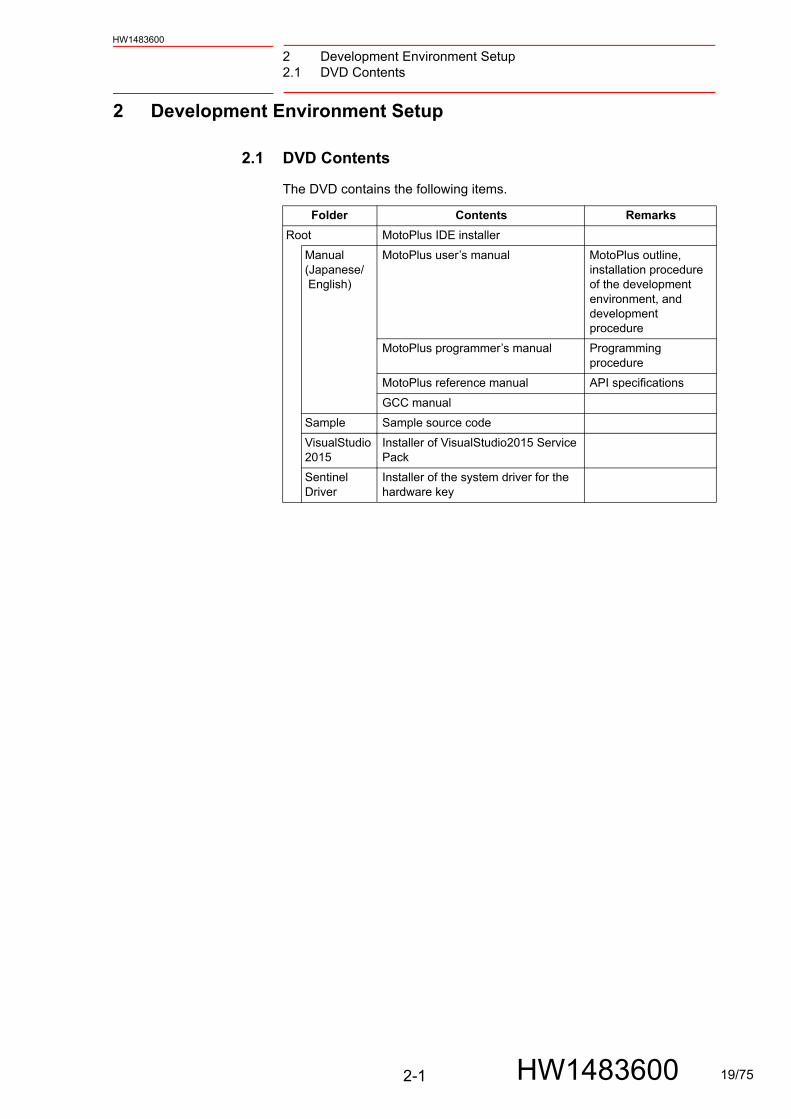
The DVD contains the following items.
Folder Contents Remarks
Root MotoPlus IDE installer
Manual(Japanese/ English)
MotoPlus user’s manual MotoPlus outline, installation procedure of the development environment, and development procedure
MotoPlus programmer’s manual Programming procedure
MotoPlus reference manual API specifications
GCC manual
Sample Sample source code
VisualStudio2015
Installer of VisualStudio2015 Service Pack
Sentinel Driver
Installer of the system driver for the hardware key
2-1 HW1483600 19/75

2 Development Environment Setup2.2 Installation of Development Environment Software
HW1483600
2.2 Installation of Development Environment Software
Install MotoPlus IDE as indicated in the following procedure.
1. Insert the MotoPlusIDE installation DVD in the DVD slot on the PC.If AutoRun is enabled, the installation starts.If not, run “setup.exe” in the DVD.
2. Install MotoPlusIDE.The installation window of the MotoPlusIDE appears.
3. Click 〔Next>〕.The following window appears to specify the installation destination folder.
2-2 HW1483600 20/75

2 Development Environment Setup2.2 Installation of Development Environment Software
HW1483600
4. Click 〔Next>〕.The following confirmation window for installation appears.
5. Click 〔Next>〕.The progress of the installation appears.When the installation is completed properly, the following window appears.Upon completing the installation, shortcuts of MotoPlusIDE are added on the desktop and in the Programs folder of the Start menu.
6. After completing the installation, restart the PC.
7. Install the system driver for the hardware key.After restarting the PC, start “SentinelSystemDriverInstaller7.5.9.exe” in the “SentinelDriver” folder in the installation DVD.
8. Install the hardware key.Insert the provided hardware key into any available USB connector. The message “Your new hardware is installed and ready to use.” will appear in the taskbar.
2-3 HW1483600 21/75
2 Development Environment Setup2.3 Installation of TELNET Connection Utility
HW1483600
2.3 Installation of TELNET Connection Utility
To debug the MotoPlus application, connect the YRC1000 and the PC via TELNET and describe using printf() in the application program. Thus, the TELNET connection utility is prepared. Install it by following the procedure below.
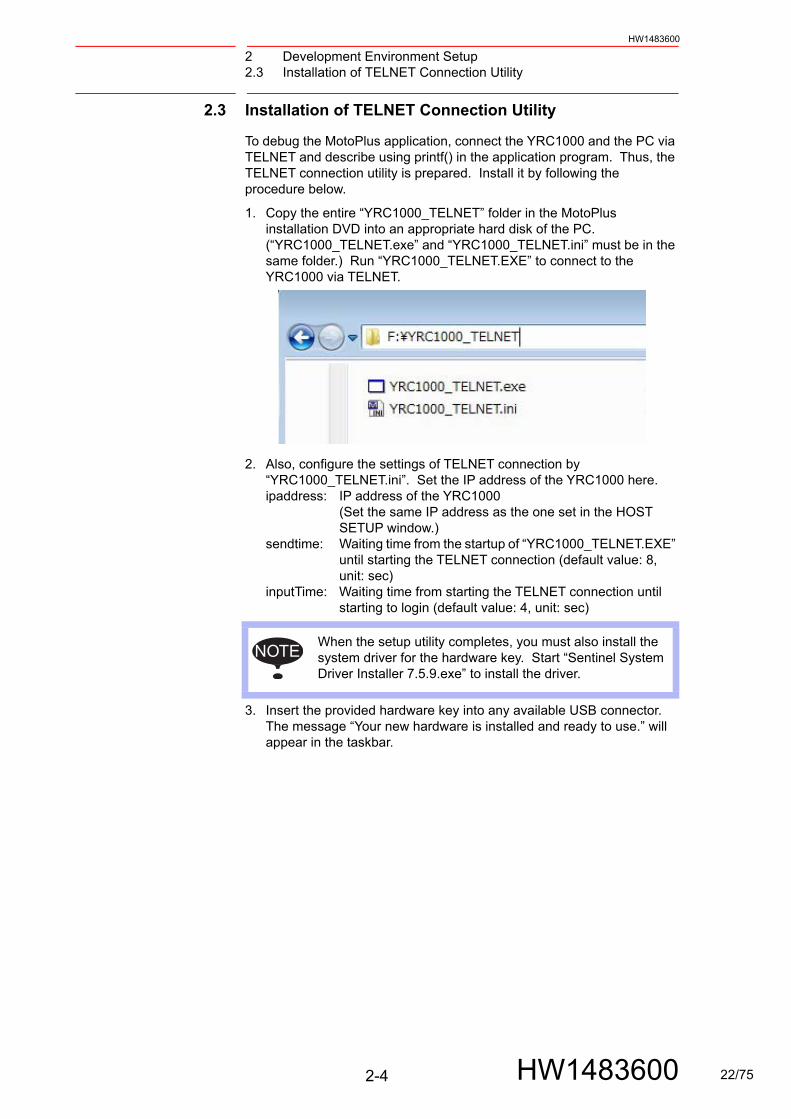
1. Copy the entire “YRC1000_TELNET” folder in the MotoPlus installation DVD into an appropriate hard disk of the PC. (“YRC1000_TELNET.exe” and “YRC1000_TELNET.ini” must be in the same folder.) Run “YRC1000_TELNET.EXE” to connect to the YRC1000 via TELNET.
2. Also, configure the settings of TELNET connection by “YRC1000_TELNET.ini”. Set the IP address of the YRC1000 here. ipaddress: IP address of the YRC1000
(Set the same IP address as the one set in the HOST SETUP window.)
sendtime: Waiting time from the startup of “YRC1000_TELNET.EXE” until starting the TELNET connection (default value: 8, unit: sec)
inputTime: Waiting time from starting the TELNET connection until starting to login (default value: 4, unit: sec)
3. Insert the provided hardware key into any available USB connector. The message “Your new hardware is installed and ready to use.” will appear in the taskbar.
NOTEWhen the setup utility completes, you must also install the system driver for the hardware key. Start “Sentinel System Driver Installer 7.5.9.exe” to install the driver.
2-4 HW1483600 22/75

3 Creating Application Software3.1 Rules for Creating Program Source Code
HW1483600
3 Creating Application Software
3.1 Rules for Creating Program Source Code
Be sure to observe the following rules when creating the source code.
Refer to “Programmer’s Manual for New Language Environment MotoPlus (HW1483598)” for detailed information on programming configuration, files to be included, and sample programs.
Please remember that the source code should follow ANSI-C syntax. The only exception is that users should not define a “main (…)” function. This is replaced by “mpUsrRoot(…)”.
1. Up to 32 one-byte characters can be used for a file name. Up to 16 two-byte characters can also be used. File names are case-sensitive. Set “.c” as the extension.
2. Put “#include<MotoPlus.h>” at the top of each source code file. When “MotoPlus.h” is included, the information of all services provided by MotoPlus is included.
3. The application entry point is the function which is called from the system software when the YRC1000 is started. This function must be described as: void mpUsrRoot (int arg1, int arg2, int arg3, int arg4, int arg5, int arg6, int arg7, int arg8, int arg9, int arg10) Be sure to describe mpExitUserRoot at the end of the mpUserRoot function.
void mpUsrRoot (int arg1, int arg2, int arg3, int arg4, int arg5, int arg6, int arg7, int arg8, int arg9, int arg10)
{/* 10 parameters from arg1 to arg10*/·mpExitUsrRoot;// End of mpUsrRoot program (End of the task)
}
e.g. filename: abc.c
* The original argument of arg1 to arg10 is mpUsrRoot. arg1 to arg10 are prepared to receive arguments in the future. At present, arg1 is the function name of the user entry, and arg2 to arg 10 are reserved for the manufacturer (if referenced, all of them are “0”).
NOTE
The task “mpUsrRoot” has a high priority to start other appli-cation tasks and initialize the entire application quickly. Due to its high task priority, if a time-consuming process (100 microseconds or longer) is done in this task, the processing time for the robot control becomes insufficient. Then the system alarm may occur or the programming pendant or the HOLD button may freeze. Thus, as the sample program (refer to “Chap.17.3 Task Control Sample Program” in “Pro-grammer’s Manual for New Language Environment MotoP-lus (HW1483598)”, make sure to complete the task “mpUsrRoot” after starting up another application or creat-ing a semaphore.
3-1 HW1483600 23/75

3 Creating Application Software3.2 Creating MotoPlus Project
HW1483600
3.2 Creating MotoPlus Project
Start MotoPlus IDE from the Windows Start menu. The window of MotoPlus IDE, similar to that of Visual Studio, appears.
To create a MotoPlus application, create a project first. The project is the unit to manage the source files for each application program.
All of the source files required for the application are included in the project. Double-click an existing project in Windows Explorer, then MotoPlus IDE automatically starts and the project is opened.
To create a new project, go to the top menu bar, then click File > New > Project. Then, the following window appears.
Type a project name (up to 32 single-byte characters which can be used as a file name), then a folder to store the source file will be automatically created (the folder can be located anywhere in the PC). Select the type of the MotoPlus file to be created from “Project Settings”.
There are following options for “Project Settings”:
1. Executable program (default): Creates an *.out file. This is a normal MotoPlus application which can be executed as a task of the YRC1000.
2. MotoPlus library file: Creates a static library file (*.yrcLib). This type of library cannot be executed on the YRC1000 but can be called from MotoPlus application. Thus, import it from another project file to use it.
When a new project is created, the source code template “mpMain.c” opens. Use it if necessary. Delete it if not necessary.
3-2 HW1483600 24/75

3 Creating Application Software3.3 Outline of MotoPlus IDE
HW1483600
3.3 Outline of MotoPlus IDE
The left pane of MotoPlus IDE contains the project tree. This lists all source files, header files, and library files that will be compiled when the project is built. To edit a file that is in the project tree, double-click the filename, then the contents of the file appears as a new tab in the source editor window. See fig. 3-1 “Main interface for MotoPlus IDE” .
Fig. 3-1: Main interface for MotoPlus IDE
Right-click on the project tree to show the following options:
1. Remove a file from the project
2. Create sub-folders to organize files (click and drag files to move them to a new folder)
3. Add files to the project (new or existing)
4. Add MotoPlus libraries to the project
5. Compile the code and build your program
The source editor has the following features:
• Automatic syntax highlighting of keywords
• Automatic indenting
• Undo/redo up to 50 actions
• Tab for each open document for easy navigation between files
• Right-click menu to instantly open the header file that has been included
• Search for text in the entire project
3-3 HW1483600 25/75
3 Creating Application Software3.4 Text Search
HW1483600
3.4 Text Search
To search for text, go to the top menu bar and click Edit > Find and Replace (shortcut is Ctrl + f). Then, the “Find” dialog appears. When “Find All” is selected, the cursor will not immediately go to the next searched text. Instead, the bottom pane will change to the “Find Results” tab to show the search results. Double-click a result in this pane to go to the corresponding source code tab and move the cursor to the searched text.
3.5 MotoPlus Library Files
A MotoPlus library file (*.yrcLib) is a file containing the source code which is already compiled. After the source code is compiled to .mpLib format, it cannot be edited or viewed. (The library can be distributed and used without distributing the source code.)
To create a library file, select “Create MotoPlus Library file” when creating a new project. This library can be used by other projects, but in this case, prepare an appropriate header file (*.h) in advance. Also, DO NOT use mpUsrRoot() function for the library.
To use the library file in an executable project, go to the top menu bar and click Project > Add MotoPlus library file. Then you can locate an .mpLib file on your computer. When you select the file, it will be copied to the current project folder along with the corresponding header file. If the header is not present (or is named differently), it will not be copied. In this case, you must refer to the library documentation provided by the creator of the library. When you build your project, the compiled code from the library will be added to the final executable object (.out).
3.6 Program Build (Compile/Link)
To compile the created source code and build either an executable object (*.out) or a library file (*.yrcLib), go to the top menu bar and click Build > Build Project. This will save any changes made to the project.
The bottom pane will automatically switch to the “Output” tab during a build attempt. The text box in this window will log the build process. The “Build Errors” tab will display any errors or warnings given by the compiler. If there is a fault in the source code, it will indicate the line number where it encountered the error. To quickly go to the appropriate file and line number, just double-click the error message. Please note that due to the structure of C language, an error on any line could be caused by a fault in any line above the error. If there is a fault in an include file, the error message may not even indicate the correct file.
If the Output window indicates the build was successful, you will be able to locate your *.out file in a folder labeled “output”. This folder will be in the directory of your project file. If your project is set to build a library file, the output folder will contain the *.yrcLib file and the *.h file.
3-4 HW1483600 26/75

3 Creating Application Software3.7 Changing Build Settings
HW1483600
3.7 Changing Build Settings
To change build settings, select “Build”, then “Build settings...” under the menu.
The sample program in the DVD is created in the default installation folder (C:Program Files\Yaskawa\MotoPlusIDE_YRC). Thus, when it is installed in another folder, the build settings must be initialized.
To initialize the build settings, check “Edit Enable/Disable” and click on the button “Restore factory defaults”.
Also, compile options, build options, etc. can be changed by using “Compile Code Command” or “Build Executable Command”, but basically, use the default settings.
3-5 HW1483600 27/75

3 Creating Application Software3.8 How to Use the DX200 Projects on YRC1000
HW1483600
3.8 How to Use the DX200 Projects on YRC1000
YRC1000 is different from DX200 in the execution environment of MotoPlus application. Therefore the MotoPlus application for DX200 is unavailable on YRC1000.
The MotoPlus application available on YRC1000 can be made by using the application for DX200. The procedure is as follows:
1. Copy the folder which includes the MotoPlus application for DX200 by another name.(When the folder (C:\My_First_MP_Project\Sample) includes any project, copy the folder (C:\My_First_MP_Project\Sample) and make a new folder (C:\My_First_MP_Project\Sample1)).
2. Open the copied folder and change the file extension of “Sample.dnProj” to “Sample.yrcProj” in the .Change the extension of a project file “Sample.dnProj” in the copied folder to “Sample.yrcProj”.
3. Double-click the file Sample.yrcProj and start the MotoPlusIDE_YRC.
4. Click the MotoPlusIDE_YRC menu “build”, then click “Build Setting...”.
5. Click the button [Restore Factory Defaults] in the “Build Settings” dialogue. That makes the build settings into the default state.
6. Click the MotoPlusIDE_YRC menu “build”, then click “Build Project F7”. When the output window “Build Successful!” appears, making the MotoPlus application for YRC1000 is completed.
3.8.1 Difference Points of the API
Changed the following API specifications for the YRC1000.
When the application created for the DX200 is operated by the YRC1000, the transplantation work is required.
(1) mpGetRtc
The return value for the mpGetRtc ( ) is int type for the DX200 and FS100, however, for the YRC1000, the value is the float type.
In the YRC1000, mpGetRtc ( ) returns the value less than 1. Correct the return value of the mpGetRtc ( ) to the float type.
(2) Direction of the absolute angle position for the robot
For controllers DX200 or earlier, in the axis which has a gear ratio set to a negative value, the positive and negative directions of the absolute angle position and the pulse position were set to be the opposite direction.
However, for controllers YRC1000 or later, the direction of the absolute angle position and the direction of the pulse position are set to be the same direction. For the application which operates the robot by using the absolute angle, some robot operations may be performed in the opposite direction. In the case of transplantation work, confirm the direction of the robot operation, and correct the direction if necessary.
3-6 HW1483600 28/75

4 Valid/Invalid Setting of MotoPlus FunctionHW1483600
4 Valid/Invalid Setting of MotoPlus Function
The following is the procedure to set the MotoPlus function to valid.
1. Start the YRC1000 in MAINTENANCE MODE, and change to the “MANAGEMENT MODE” in the security mode.
2. Select {SYSTEM} under the main menu, then select {SETTING}.
– The option function window appears.
3. Select “MotoPlus FUNC.”
– The selection list “NOT USED”/“USED” appears.
4-1 HW1483600 29/75

4 Valid/Invalid Setting of MotoPlus Function
HW1483600
4. Select “USED”.
– The confirmation dialog appears.
5. Select “YES” on the confirmation dialog.
– If the memory I/F expansion option is valid, the SRAMDRV.DAT initialization confirmation dialog appears. If the memory I/F expansion option is invalid, the dialog doesn’t appear and the MotoPlus function becomes valid.
6. Select “YES” on the SRAMDRV.DAT initialization confirmation dialog.
– The MotoPlus function becomes valid.
4-2 HW1483600 30/75
4 Valid/Invalid Setting of MotoPlus FunctionHW1483600
The following is the procedure to set the MotoPlus function to invalid.
1. Start the YRC1000 in MAINTENANCE MODE, and change to the “MANAGEMENT MODE” in the security mode.
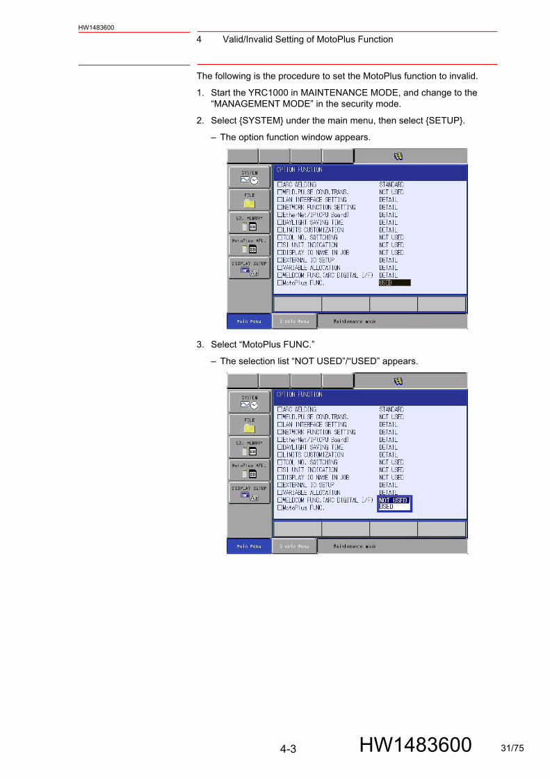
2. Select {SYSTEM} under the main menu, then select {SETUP}.
– The option function window appears.
3. Select “MotoPlus FUNC.”
– The selection list “NOT USED”/“USED” appears.
4-3 HW1483600 31/75

4 Valid/Invalid Setting of MotoPlus Function
HW1483600
4. Select “NOT USED”.
– The setting change confirmation dialog appears.
5. Select “YES” on the confirmation dialog.
– The MotoPlus function becomes invalid.
4-4 HW1483600 32/75

5 Installation and Start-up of Application Program5.1 Installation of Application Program in Maintenance Mode
HW1483600
5 Installation and Start-up of Application Program
5.1 Installation of Application Program in Maintenance Mode
1. Load functionLoad the application program and install it by following the instructions below.
(1) Set the security mode to the MANAGEMENT MODE. Select the main menu {MotoPlus APL.}. Then {LOAD (USER APPLICA-TION)}, {FILE LIST}, {DELETE}, {DEVICE}, {FOLDER}, and {MotoPlus FUNC. SETTING} appear as submenus.
(2) Specify the file location. Select an appropriate file location with the submenus {DEVICE (to select SD/USB)} and {FOLDER (to select the folder which has the application program)}.
(3) Select and load a file.
• Select the submenu {LOAD (USER APPLICATION)}. Then, “*.out” files in the specified folder appear as shown below.
5-1 HW1483600 33/75

5 Installation and Start-up of Application Program5.1 Installation of Application Program in Maintenance Mode
HW1483600
• Move the cursor and press [SELECT]. Then, the selection indi-cator “ ” appears on the left of the application file name. Press [SELECT] again to clear “ ”.
• Press [ENTER], then the following confirmation dialog box appears.
• When {YES} is selected and the selected application file contains the file which already exists in the YRC1000, the following confir-mation dialog box appears. Select “YES” to load.
5-2 HW1483600 34/75

5 Installation and Start-up of Application Program5.1 Installation of Application Program in Maintenance Mode
HW1483600
2. ListSelect the submenu {FILE LIST}. Then, the list of the application files which already exist in the YRC1000 appears.
3. Deletion of application programBy the submenu {DELETE}, the application file which already exists in the YRC1000 can be deleted.
(1) Move the cursor and press [SELECT]. Then, the selection indica-
tor “ ” appears on the left of the application file name. Press
[SELECT] again to clear “ ”.
(2) Press [ENTER], then the following confirmation dialog box appears.
5-3 HW1483600 35/75
5 Installation and Start-up of Application Program5.1 Installation of Application Program in Maintenance Mode
HW1483600
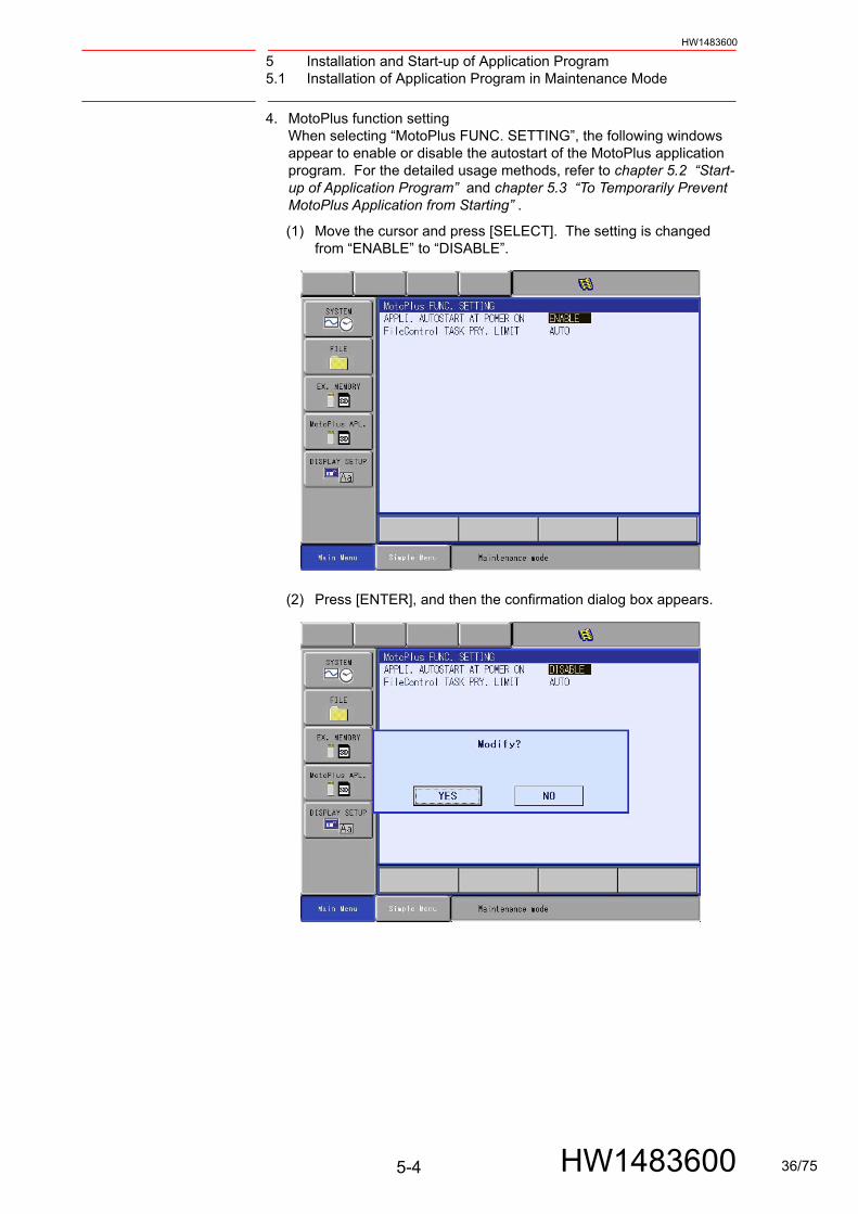
4. MotoPlus function setting When selecting “MotoPlus FUNC. SETTING”, the following windows appear to enable or disable the autostart of the MotoPlus application program. For the detailed usage methods, refer to chapter 5.2 “Start-up of Application Program” and chapter 5.3 “To Temporarily Prevent MotoPlus Application from Starting” .
(1) Move the cursor and press [SELECT]. The setting is changed from “ENABLE” to “DISABLE”.
(2) Press [ENTER], and then the confirmation dialog box appears.
5-4 HW1483600 36/75

5 Installation and Start-up of Application Program5.1 Installation of Application Program in Maintenance Mode
HW1483600
(3) Select {YES}.
–When {YES} is selected on the confirmation dialog box, the parameter is set automatically, and then it returns to the MotoPlus setting window.
5-5 HW1483600 37/75

5 Installation and Start-up of Application Program5.2 Start-up of Application Program
HW1483600
5.2 Start-up of Application Program
When the YRC1000 is turned ON, the application program is loaded automatically and started.
<Limitations>
• Only one “*.out” file can be loaded. Thus, install only one applica-tion. If two or more applications are installed, the alarm 1020: “MOTOPLUS APPLICATION LOAD ERROR [1]” occurs on loading. The error status can be checked by reading $B051 from the job.
• The loadable memory size is up to 2 Mbyte as the total of the code area and the static memory area. If it is more than 2 Mbyte, the start-up fails and the alarm 1020: “MOTOPLUS APPLICATION LOAD ERROR [4]” occurs on loading. The error status can be checked by reading $B051 from the job.
$B051 0: The application is loaded successfully on start-up.1: The number of files exceeds the limit. 2: The memory is insufficient. (Available memory area is
less than 3 Mbyte.) 3: APPLICATION folder cannot be found in the SD. 4: The size of the MotoPlus application exceeds the limit.
5.3 To Temporarily Prevent MotoPlus Application from Starting
Due to a problem of the application program, the system may hang up during robot operation, and then the YRC1000 may not start normally. For recovery, it is necessary to start the YRC1000 normally while preventing the application program from operating. In this case, it is necessary to start the YRC1000 in the MAINTENANCE mode, make the settings so that the application program does not operate, start the YRC1000 normally, and operate the robot. Follow one of the following two procedures:
1. Start the YRC1000 in the MAINTENANCE mode, set the security mode to the MANAGEMENT MODE. Select “MotoPlus APL.”, then “DELETE” to delete the application.
2. Start the YRC1000 in the MAINTENANCE mode, set the security mode to the MANAGEMENT MODE. Select “MotoPlus APL.”, then “MotoPlus FUNC. SETTING” to show the setting window. Then set “APPLI. AUTOSTART AT POWER ON” to “DISABLE”.
If the above problem occurs during robot operation, choose the procedure 2. The above problem during robot operation may be caused by a specific condition. If the MotoPlus application is deleted with the procedure 1, after the specific condition is cleared, the MotoPlus application must be loaded again in the SD for recovery. In this case, if the application to be loaded does not exist there, the application cannot operate and the system cannot recover.
5-6 HW1483600 38/75

6 User Defined File6.1 Saving in and Reading from External Memory
HW1483600
6 User Defined File
With MotoPlus, user defined files can be created, read, written, deleted, etc. from an application by using the file control.
These files can be saved in or read from external memory (SD or USB) by using the programming pendant.
6.1 Saving in and Reading from External Memory
Saved files can be checked on the display of the programming pendant as
“USER DEFINED FILE”. The files can be saved in or read from external memory such as SD or USB on this display.
6.1.1 Procedure to Save or Read User Defined File
1. Start in the normal mode, and select {EX. MEMORY}, then {SAVE} or {LOAD}.
2. Select {USER DEFINED FILE}.
6-1 HW1483600 39/75

6 User Defined File6.1 Saving in and Reading from External Memory
HW1483600
3. Select a file to be saved in external memory or to be loaded from external memory to the controller.
4. appears on the left of the selected file. Multiple files can also be selected.
5. Select a file and press [ENTER], then the following window appears. Select “YES”.
6-2 HW1483600 40/75

6 User Defined File6.2 Initialization of User Defined File
HW1483600
6.2 Initialization of User Defined File
1. Start the controller in the maintenance mode. Then, select {Main Menu}, {FILE}, then {INITIALIZE}.
2. Select “USER DEFINED FILE”.
3. Select “SRAM RAM DRIVE SRAMDRV .DAT”.
6-3 HW1483600 41/75

6 User Defined File6.2 Initialization of User Defined File
HW1483600
4. appears as shown below.
5. Press [ENTER], then the following window appears. Select {YES}.
6-4 HW1483600 42/75

6 User Defined File6.3 Setting of File Control Task Priority Limit
HW1483600
6.3 Setting of File Control Task Priority Limit
Only the normal priority (MP_PRI_TIME_NORMAL) is used as the task priority for the file control API.
When the file control API is used from the task with higher priority, the operation differs depending on the setting of the parameter S2C1101 as shown in the following table.
This setting can also be changed by using “FileControl TASK PRY. LIMIT” in the maintenance mode.
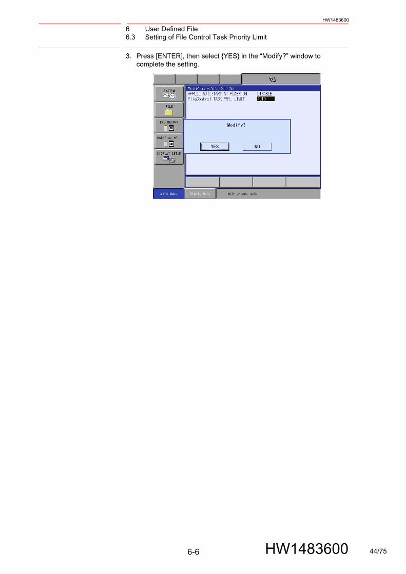
6.3.1 Changing File Control Task Priority Limit
1. Start in the maintenance mode. Select {Main Menu}, {MotoPlus APL.}, then {MotoPlus FUNC. SETTING}.
2. Press [SELECT] at “FileControl TASK PRY. LIMIT” to select “LIMITED” or “AUTO”.
S2C1101 FileControl TASK PRY. LIMIT Operation
0 LIMITED The API returns an error.
1(default value)
AUTO Temporarily changes the task priority to MP_PRI_TIME_NORMAL and executes the API.
6-5 HW1483600 43/75
6 User Defined File6.3 Setting of File Control Task Priority Limit
HW1483600
3. Press [ENTER], then select {YES} in the “Modify?” window to complete the setting.
6-6 HW1483600 44/75

7 Debugging7.1 Debugging Environment
HW1483600
7 Debugging
7.1 Debugging Environment
For the debugging environment, connect the PC for development with the RUN-TIME debugger of the controller OS via Telnet. Then you can insert printf() or puts() in the application source code to display the messages about variable and program execution states when debugging.
NOTE
Delete all the debugging codes described in the source code after completing debugging. Otherwise, the process-ing time of printf() and puts() may affect the system and may cause insufficient processing time, etc. during robot opera-tion.
NOTE
With the Telnet function, debug only the tasks with normal priority. For debugging the tasks with high priority (the tasks started with the task priority: MP_PRI_IO_CLK_TAKE, MP_PRI_IP_CLK_TAKE, or MP_TIME_CRITICAL, or the task “mpUsrRoot”), use the variables of the YRC1000. This is because, if printf() or puts() is done with a high priority task, the processing time for the robot operation control is consumed, and a system alarm may occur due to insuffi-cient processing time.
NOTE
When programming in C language, the pointer variable which stores the memory address can be used. If the pointer variable is set incorrectly, the system memory area may be rewritten. If the system memory area is rewritten, critical problems occur, e.g., the software hangs up (the hang-up status is detected by a CPU exception or the watchdog check func-tion, then the servo power turns OFF and the system shuts down), the robot stops its operation due to an alarm, or the programming pendant becomes inoperable. If the system memory operation is incorrect, the application itself may not operate as it is designed. Thus, by testing adequately, the error location can be found. Check the functions of the application software well enough, and make sure that all functions operate as designed.
NOTE
When using the SHELL debugging function of the controller OS which becomes available by connecting with the YRC1000 via Telnet, a system alarm may occur due to insufficient processing time for robot operation. Do NOT use the SHELL debugging function.
7-1 HW1483600 45/75

7 Debugging7.2 Connecting YRC1000 with PC
HW1483600
7.2 Connecting YRC1000 with PC
Connect the PC for development with the YRC1000. Then the PC can be used as the terminal to debug programs via Telnet.
As shown below, connect an Ethernet cable (shielded twisted-pair, CAT 5 or greater) to the LAN connector CN106 (LAN2) that is mounted on the front of the ACP01 circuit board in the CPU rack of the YRC1000 controller.
To use the Ethernet service provided by MotoPlus, use a commercially available hub and set up the connection as shown below.
Ethernet
S-
高
選 択
X-S+
X+
L-Y-
L+Y+
U-Z-
U+Z+
7- 7+
R-X-
R+X+
B-Y-
B+Y+
T-Z-
T+Z+
低
高 速
9
6
3
-.
2
5
87
4
1
0
ACP01
CN105
CN106
Development PC
Robot Controller
Ethernet
S-
高
選 択
X-S+
X+
L-Y-
L+Y+
U-Z-
U+Z+
7- 7+
R-X-
R+X+
B-Y-
B+Y+
T-Z-
T+Z+
低
高 速
9
6
3
-.
2
5
87
4
1
0
ACP01
CN105
CN106
Robot Controller
Development PC
Hub
Devices such as Visionsensor to be connected via Ethernet
7-2 HW1483600 46/75

7 Debugging7.2 Connecting YRC1000 with PC
HW1483600
NOTE
Three LAN connectors are mounted on the front of the ACP01 circuit board. Only CN106 (the middle connector) can be used for the Ethernet function that MotoPlus sup-ports.
7-3 HW1483600 47/75

7 Debugging7.3 Debugging via Telnet Communication
HW1483600
7.3 Debugging via Telnet Communication
The RUN-TIME debugger for the YRC1000 system software, can be connected with a debug PC via Telnet to provide the user with various types of debugging function. Thus, printf() and puts() functions can be inserted in the application source code, and the desired memory content or message can be shown on the Telnet terminal.
With this procedure, debug only the tasks with normal priority. For debugging the tasks with high priority (the tasks started with the task priority: MP_PRI_IO_CLK_TAKE, MP_PRI_IP_CLK_TAKE, or MP_TIME_CRITICAL, or the task “mpUsrRoot”), refer to chapter 7.4 “Debugging by User Variables of YRC1000” .
7.3.1 Operation Procedure
1. Set the IP address, etc. The Ethernet communication settings corresponding to your environment (such as the IP address setting at the YRC1000 side) must be performed in the maintenance mode.The procedure is as follows:
(1) Turn OFF the YRC1000 then back ON while pressing the [MAIN MENU] to start the maintenance mode.
(2) Select {SYSTEM} under the main menu, then select {SECURITY}. Then, change the security mode to the MANAGEMENT MODE.
NOTE
If the Telnet function is enabled, an alarm such as “0500: SEGMENT PROC NOT READY” may occur when the YRC1000 is started. This is because the Telnet task of the YRC1000 side is per-formed with a high priority, so processing of other system tasks are not performed normally. If such an alarm occurs, restart the YRC1000.
Also, after completing debugging, make sure to set the Tel-net function to INVALID (S2C1119 = 0).
7-4 HW1483600 48/75

7 Debugging7.3 Debugging via Telnet Communication
HW1483600
(3) Select {SYSTEM} under the main menu, then select {SETUP}. In the setup window, select {OPTION} to open {NETWORK}. In the NETWORK window, select “DETAIL” for “HOST SETUP”.
(4) Setup the IP address in HOST SETUP window. Nomal setting for the IP address is 192.168.255.1. Ensure the PC IP address is on the same subnet as the YRC1000. In the case of the setting for the following YRC1000, the setting for PC is as follows. IP adrress:192.168.255.xx (xx: 0-255, decimal number, different from YRC1000 value), Subnet mask: 255.255.255.0
2. Restrictions on the IP address setting: The Ethernet function on the YRC1000 does not support “10.0.0.xx” in the local IP address (xx: 0-255, decimal number). Thus, DO NOT use “10.0.0.xx” for the IP address.
7-5 HW1483600 49/75

7 Debugging7.3 Debugging via Telnet Communication
HW1483600
3. Restrictions on communication ports: For the Ethernet function of the YRC1000, the system occupies the specified ports for UDP and TCP. Thus, the port numbers less than 10500 cannot be used for MotoPlus applications. Also, the ports to be used by the system may be added or changed depending on the YRC1000 software version. If your robot is using any optional functions related to the YRC1000 Ethernet function, be sure not to use the port numbers that are described in the instruction manual for each optional function.
4. Set the fixed IP address (192.168.255.9) as the network setting of the PC side. (“192.168.255.” is the same as the YRC1000 setting.)
(1) Select Control Panel and then double-click “Network connections”.
(2) Double-click “Local Area Connection”.
(3) Open the “General” window and select Internet protocol (TCP/IP), then click “Properties”.
(4) Check “Use the following IP address”.
(5) Enter “192.168.255.9” for the IP address.
(6) Enter “255.255.255.0” for the subnet mask.
5. Debugging via Telnet Communication
Execute the automatical log-in tool “YRC1000_TELNET.EXE” while MOTOMAN window is shown.
When Telnet connection succeeds, prompt becomes to ” → ”, Run debugger of the OS of the controller starts automatically.
7-6 HW1483600 50/75
7 Debugging7.3 Debugging via Telnet Communication
HW1483600
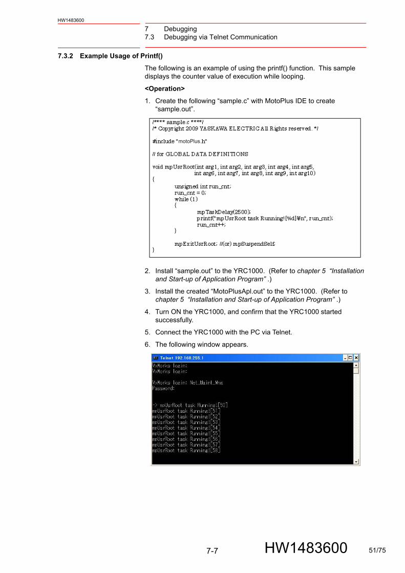
7.3.2 Example Usage of Printf()
The following is an example of using the printf() function. This sample displays the counter value of execution while looping.
<Operation>
1. Create the following “sample.c” with MotoPlus IDE to create “sample.out”.
2. Install “sample.out” to the YRC1000. (Refer to chapter 5 “Installation and Start-up of Application Program” .)
3. Install the created “MotoPlusApl.out” to the YRC1000. (Refer to chapter 5 “Installation and Start-up of Application Program” .)
4. Turn ON the YRC1000, and confirm that the YRC1000 started successfully.
5. Connect the YRC1000 with the PC via Telnet.
6. The following window appears.
motoPlus
7-7 HW1483600 51/75

7 Debugging7.4 Debugging by User Variables of YRC1000
HW1483600
7.4 Debugging by User Variables of YRC1000
Debugging with printf() or puts() for the tasks with high priority (the tasks started with the task priority: MP_PRI_IO_CLK_TAKE, MP_PRI_IP_CLK_TAKE, or MP_TIME_CRITICAL, or the task “mpUsrRoot”) may cause insufficient processing time for the robot operation control task. Thus, use the user variables of the YRC1000 (B variable, I variable, D variable, and R variable) to debug.
In this case, use the API for writing to the variable “mpPutVarData()” in the MotoPlus application to describe debug information, then debug while checking the data in the VARIABLE window on the programming pendant.
7-8 HW1483600 52/75

8 Development Support Tool8.1 Outline
HW1483600
8 Development Support Tool
8.1 Outline
8.1.1 Introduction
This chapter explains the functions of the tool to support development of the MotoPlus application (hereafter referred to as "the application").
To use the development support tool, the optional Ethernet function is required.
8.1.2 Overview of Functions
The MotoPlus application development support tool contains the following functions.
No. Function Details
1 Online Download A function which downloads the application from MotoPlusIDE to the robot controller (hereafter referred to as "the controller").
2 Application Property List A function which displays the detailed information, such as the operation status of the application.
3 Port Debug A function which measures the processing time of the application.
4 Copy Protection A function which prevents applications that are copied illegally from being used.
8-1 HW1483600 53/75
8 Development Support Tool8.2 Using the Support Tool
HW1483600
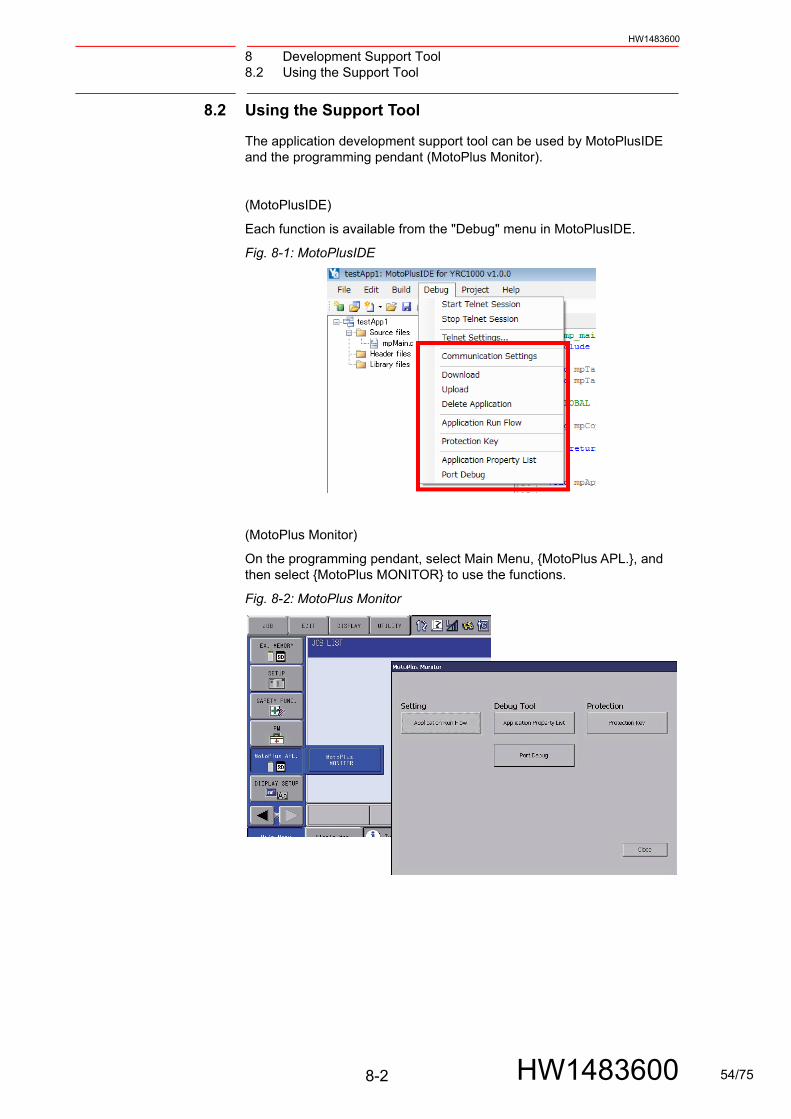
8.2 Using the Support Tool
The application development support tool can be used by MotoPlusIDE and the programming pendant (MotoPlus Monitor).
(MotoPlusIDE)
Each function is available from the "Debug" menu in MotoPlusIDE.
Fig. 8-1: MotoPlusIDE
(MotoPlus Monitor)
On the programming pendant, select Main Menu, {MotoPlus APL.}, and then select {MotoPlus MONITOR} to use the functions.
Fig. 8-2: MotoPlus Monitor
8-2 HW1483600 54/75
8 Development Support Tool8.2 Using the Support Tool
HW1483600
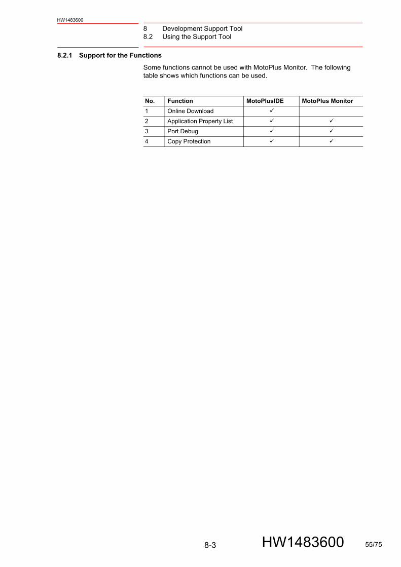
8.2.1 Support for the Functions
Some functions cannot be used with MotoPlus Monitor. The following table shows which functions can be used.
No. Function MotoPlusIDE MotoPlus Monitor
1 Online Download
2 Application Property List
3 Port Debug
4 Copy Protection
8-3 HW1483600 55/75
8 Development Support Tool8.3 Basic Settings
HW1483600
8.3 Basic Settings
8.3.1 Connecting a PC with the YRC1000
Connect PC with the YRC1000 by using the Ethernet cable as shown in chapter 7.2 “Connecting YRC1000 with PC” .
8.3.2 Communication Settings
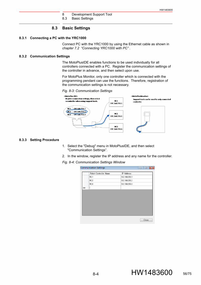
The MotoPlusIDE enables functions to be used individually for all controllers connected with a PC. Register the communication settings of the controller in advance, and then select upon use.
For MotoPlus Monitor, only one controller which is connected with the programming pendant can use the functions. Therefore, registration of the communication settings is not necessary.
Fig. 8-3: Communication Settings
8.3.3 Setting Procedure
1. Select the "Debug" menu in MotoPlusIDE, and then select "Communication Settings”.
2. In the window, register the IP address and any name for the controller.
Fig. 8-4: Communication Settings Window
8-4 HW1483600 56/75
8 Development Support Tool8.4 Online Download
HW1483600
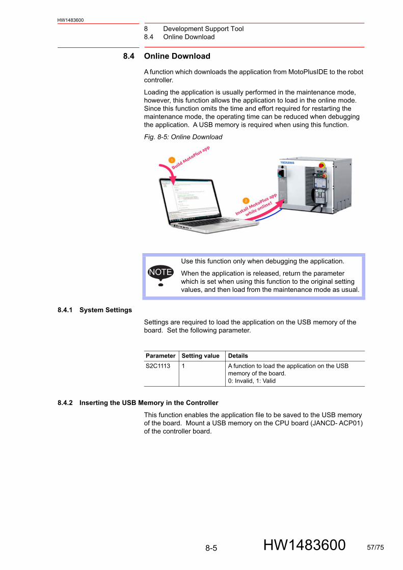
8.4 Online Download
A function which downloads the application from MotoPlusIDE to the robot controller.
Loading the application is usually performed in the maintenance mode, however, this function allows the application to load in the online mode. Since this function omits the time and effort required for restarting the maintenance mode, the operating time can be reduced when debugging the application. A USB memory is required when using this function.
Fig. 8-5: Online Download
8.4.1 System Settings
Settings are required to load the application on the USB memory of the board. Set the following parameter.
8.4.2 Inserting the USB Memory in the Controller
This function enables the application file to be saved to the USB memory of the board. Mount a USB memory on the CPU board (JANCD- ACP01) of the controller board.
NOTEUse this function only when debugging the application.
When the application is released, return the parameter which is set when using this function to the original setting values, and then load from the maintenance mode as usual.
Parameter Setting value Details
S2C1113 1 A function to load the application on the USB memory of the board.0: Invalid, 1: Valid
8-5 HW1483600 57/75
8 Development Support Tool8.4 Online Download
HW1483600
Fig. 8-6: Location of the USB on the Board
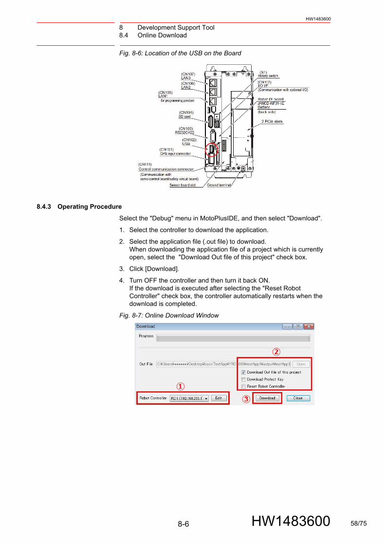
8.4.3 Operating Procedure
Select the "Debug" menu in MotoPlusIDE, and then select "Download".
1. Select the controller to download the application.
2. Select the application file (.out file) to download.When downloading the application file of a project which is currently open, select the "Download Out file of this project" check box.
3. Click [Download].
4. Turn OFF the controller and then turn it back ON. If the download is executed after selecting the "Reset Robot Controller" check box, the controller automatically restarts when the download is completed.
Fig. 8-7: Online Download Window
8-6 HW1483600 58/75

8 Development Support Tool8.5 Application Property List
HW1483600
8.5 Application Property List
This function acquires and displays the application properties. The following properties can be displayed.
• Application name
• Application version
• Application file size
• Task name
• Task executing priority
8.5.1 Operating Procedure
When using MotoPlusIDE, select the "Debug" menu, and then select "Application Property List".
When using MotoPlus Monitor, select {Application Property List}.
1. If using MotoPlusIDE, select the controller to display the properties.
2. Press {Refresh}.
Application information is displayed.
Fig. 8-8: Application Property List Window
1 2
8-7 HW1483600 59/75

8 Development Support Tool8.5 Application Property List
HW1483600
8.5.2 Setting Application Information
For the application name, the version, and the task name, the contents which are set by MotoPlus API are displayed.
Fig. 8-9: Setting the Application Information
8-8 HW1483600 60/75
8 Development Support Tool8.5 Application Property List
HW1483600
8.5.3 Setting Procedures
1. Set the application name and the version by using mpApplicationInfoNotify(). For using mpApplicationInfoNotify(), confirm the MotoPlus reference manual.
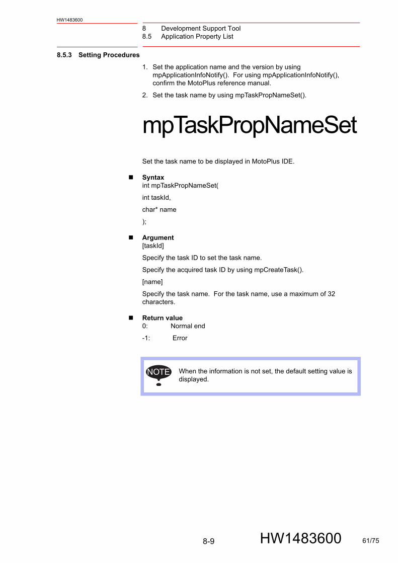
2. Set the task name by using mpTaskPropNameSet().
mpTaskPropNameSetSet the task name to be displayed in MotoPlus IDE.
Syntaxint mpTaskPropNameSet(
int taskId,
char* name
);
Argument[taskId]
Specify the task ID to set the task name.
Specify the acquired task ID by using mpCreateTask().
[name]
Specify the task name. For the task name, use a maximum of 32 characters.
Return value0: Normal end
-1: Error
NOTE When the information is not set, the default setting value is displayed.
8-9 HW1483600 61/75

8 Development Support Tool8.6 Port Debug
HW1483600
8.6 Port Debug
By executing the API for the port debug, the executing time for the task or the routine can be measured.
No. Name Details
Time Division Shows the unit [ms/div] of the time axis (the horizontal axis).
Port 0 - Port 4 Shows the measuring port. Any name can be set by using the debug port API. (For details, refer to chapter 8.6.3 “Mounting the Application” .)
Graph Area Shows the measuring data. Displays the time which is set in the Time Range.
Org Position Optional for measuring. Sets the home position of the measuring data.(For details, refer to chapter 8.6.2 “Optional for Measuring” .)
Time Range Sets the displaying time [ms] for measuring data.
Port Number Sets the number of the measuring port.
Trigger Optional for measuring. Measures by applying the trigger.(For details, refer to chapter 8.6.2 .)
Robot Controller The controller to use this function
Measure Time Optional for measuring. Measures the time.(For details, refer to chapter 8.6.2 .)
Accumulate Optional for measuring. Accumulates the measuring data.(For details, refer to chapter 8.6.2 .)
Start (Stop) Starts/stops the measuring.
Save Image / Save CSV Saves the measuring data.
Status Bar Shows the operating status.
Close Ends Port Debug.
1
2
3
4
5
6
7
8
9
10
11
12
13
14
8-10 HW1483600 62/75

8 Development Support Tool8.6 Port Debug
HW1483600
8.6.1 Measuring Procedures
When using MotoPlusIDE, select the "Debug" menu, and then select "Port Debug".
When using MotoPlus Monitor, select {Port Debug}.
1. When using MotoPlusIDE, select the controller to connect with.
2. Set the measuring conditions.Time Range Set the displaying time [ms] for measuring data.Port Number Specify the number of the measuring port.
3. Press {Start} to start measuring in Port Debug. After starting, {Start} is changed to {Stop}. Press {Stop} to finish measuring.
Fig. 8-10: Port Debug Window
8-11 HW1483600 63/75

8 Development Support Tool8.6 Port Debug
HW1483600
8.6.2 Optional for Measuring
Trigger If the option is enabled, only the measuring data is displayed when the trigger conditions are satisfied. Set the port number and trigger conditions to apply the trigger. The trigger conditions are shown below.
Up Detects the rising edge.
Down Detects the falling edge.
Up&Down Detects both edges, rising and falling.
Level Detects exceeding of the threshold level.
Fig. 8-11: Trigger
Org Position Adjusts the display of the home position of the measuring data.Depending on the adjustment of the home position, the displays differ as shown below. (When the trigger is "UP")
Fig. 8-12: Home Position
Measure Time When the option is enabled, two cursors for measuring and the time between the cursors are displayed. When adjusting the position of the cursors, any time can be measured.
Fig. 8-13: Measure Time
8-12 HW1483600 64/75

8 Development Support Tool8.6 Port Debug
HW1483600
Accumulate Accumulates the measuring data. When the option is enabled, all measuring data is drawn by overlapping. The example below shows when the option is enabled. (Trigger is Up.) The deviation of the timing when the port is turned to 0 caused the deviation of the position of the falling edge.
Fig. 8-14: Accumulate
Save Image / CSV Saves the measuring results as an image file or a CSV file.
For MotoPlusIDE, specify the destination to save and the file name, and then press the save button.
For MotoPlus Monitor, specify the external memory device to save to, and then press the save button. The results are saved in the root folder of the selected external memory device.
The name of the image file is " PortDebugImageYYYYMMDD_HHMMSS.bmp".
The name of the CSV file is " PortDebugYYYYMMDD_HHMMSS.csv".
YYYYMMDD_HHMMSS indicates the time stamp when saving (Year/Month/Date/Hour/Minute/Second).
8.6.3 Mounting the Application
Execute API for port debugging at the processing part to measure. Before using the debug port, it is necessary to execute mpDebugPortNameSet() once.
The number of ports which are available is 5. It is possible to set values from 0 to 100 for each port.
Fig. 8-15: How to Mount Port Debug
8-13 HW1483600 65/75
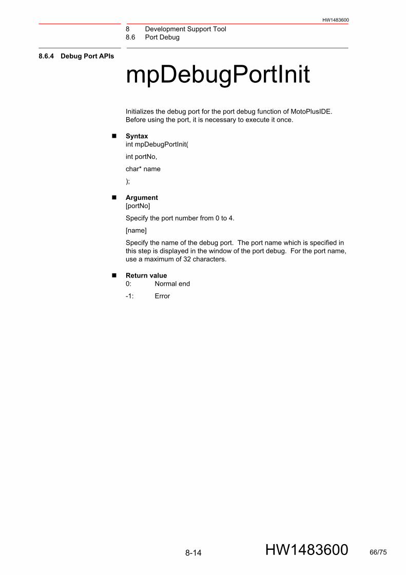
8 Development Support Tool8.6 Port Debug
HW1483600
8.6.4 Debug Port APIs
mpDebugPortInitInitializes the debug port for the port debug function of MotoPlusIDE. Before using the port, it is necessary to execute it once.
Syntaxint mpDebugPortInit(
int portNo,
char* name
);
Argument[portNo]
Specify the port number from 0 to 4.
[name]
Specify the name of the debug port. The port name which is specified in this step is displayed in the window of the port debug. For the port name, use a maximum of 32 characters.
Return value0: Normal end
-1: Error
8-14 HW1483600 66/75
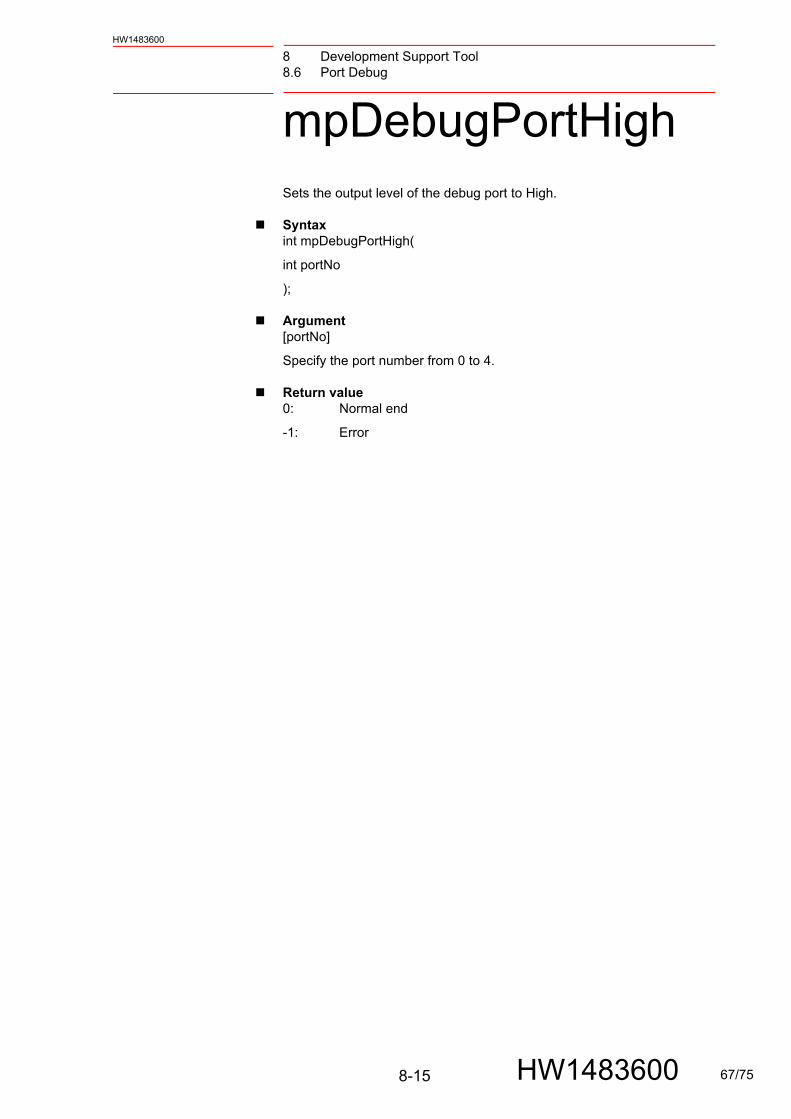
8 Development Support Tool8.6 Port Debug
HW1483600
mpDebugPortHighSets the output level of the debug port to High.
Syntaxint mpDebugPortHigh(
int portNo
);
Argument[portNo]
Specify the port number from 0 to 4.
Return value0: Normal end
-1: Error
8-15 HW1483600 67/75
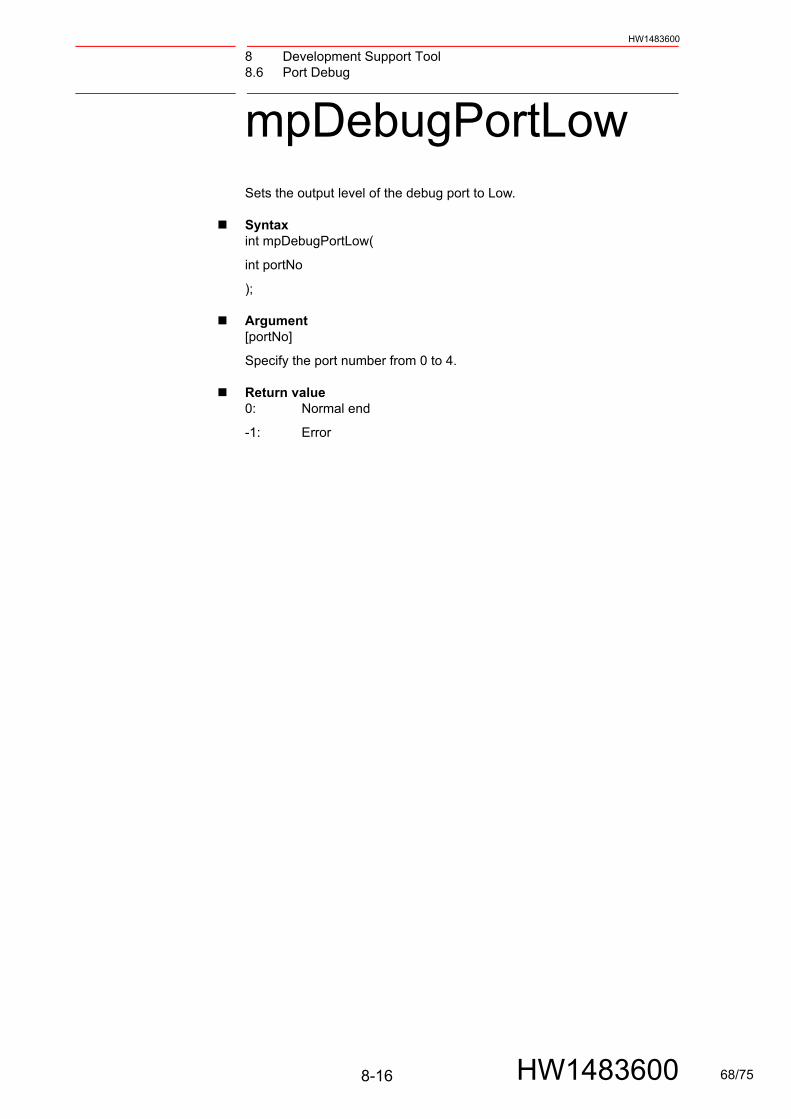
8 Development Support Tool8.6 Port Debug
HW1483600
mpDebugPortLowSets the output level of the debug port to Low.
Syntaxint mpDebugPortLow(
int portNo
);
Argument[portNo]
Specify the port number from 0 to 4.
Return value0: Normal end
-1: Error
8-16 HW1483600 68/75

8 Development Support Tool8.6 Port Debug
HW1483600
mpDebugPortLevelSetSets the output level of the debug port to a specified value.
Syntaxint mpDebugPortLevelSet(
int portNo,
int level
);
Argument[portNo]
Specify the port number from 0 to 4.
[level]
Specify the output level. The valid settable range is 0 to 100.
Return value0: Normal end
-1: Error
8-17 HW1483600 69/75

8 Development Support Tool8.7 Copy Protection
HW1483600
8.7 Copy Protection
This function enables the application to only be started on the specified controller. The use of an illegally copied application is prevented by using a different controller.
Copy protection procedures are shown below.
1. Write the protection activation process in the application source.
2. Acquire the serial file from the controller to use the application.
3. Generate a protection key from the acquired serial file.
4. Load the generated protection key to the controller.
When protection of the application is enabled, the protection key is checked before starting the application. When the key is unauthorized or the key does not exist, the application does not start.
8.7.1 Protection Activation (MotoPlusIDE)
Write the following argument (mpCopyProtectActive()) in the source file of the application. When turning the return value ON, the protection is enabled. When turning the return value OFF, the protection is disabled. If the argument is not written, protection is disabled.
long mpCopyProtectActive( void )
{
return ( ON ); // ON: Activate protection, OFF: Inactivate protection
}
8-18 HW1483600 70/75
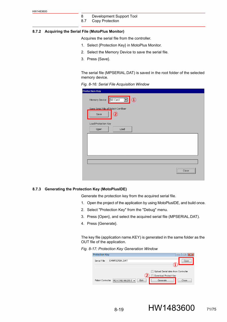
8 Development Support Tool8.7 Copy Protection
HW1483600
8.7.2 Acquiring the Serial File (MotoPlus Monitor)
Acquires the serial file from the controller.
1. Select {Protection Key} in MotoPlus Monitor.
2. Select the Memory Device to save the serial file.
3. Press {Save}.
The serial file (MPSERIAL.DAT) is saved in the root folder of the selected memory device.
Fig. 8-16: Serial File Acquisition Window
8.7.3 Generating the Protection Key (MotoPlusIDE)
Generate the protection key from the acquired serial file.
1. Open the project of the application by using MotoPlusIDE, and build once.
2. Select "Protection Key" from the "Debug" menu.
3. Press {Open}, and select the acquired serial file (MPSERIAL.DAT).
4. Press {Generate}.
The key file (application name.KEY) is generated in the same folder as the OUT file of the application.
Fig. 8-17: Protection Key Generation Window
8-19 HW1483600 71/75
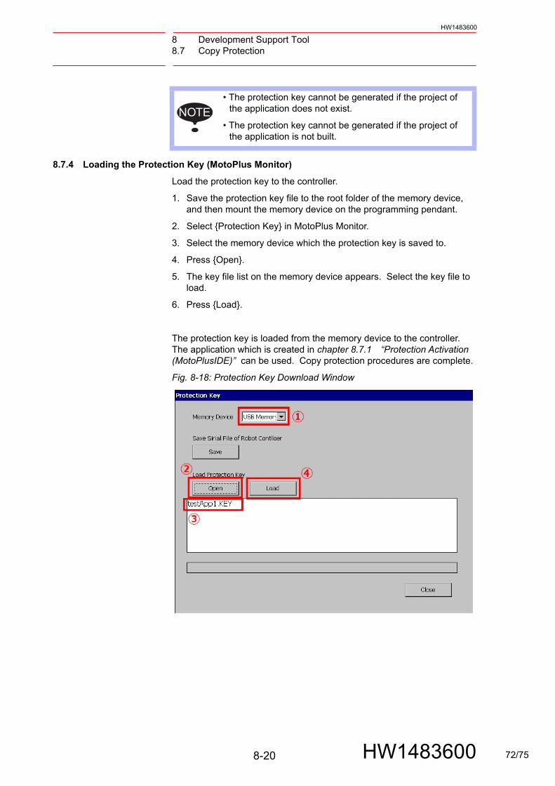
8 Development Support Tool8.7 Copy Protection
HW1483600
8.7.4 Loading the Protection Key (MotoPlus Monitor)
Load the protection key to the controller.
1. Save the protection key file to the root folder of the memory device, and then mount the memory device on the programming pendant.
2. Select {Protection Key} in MotoPlus Monitor.
3. Select the memory device which the protection key is saved to.
4. Press {Open}.
5. The key file list on the memory device appears. Select the key file to load.
6. Press {Load}.
The protection key is loaded from the memory device to the controller. The application which is created in chapter 8.7.1 “Protection Activation (MotoPlusIDE)” can be used. Copy protection procedures are complete.
Fig. 8-18: Protection Key Download Window
NOTE• The protection key cannot be generated if the project of
the application does not exist.
• The protection key cannot be generated if the project of the application is not built.
8-20 HW1483600 72/75
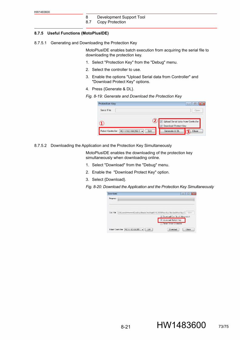
8 Development Support Tool8.7 Copy Protection
HW1483600
8.7.5 Useful Functions (MotoPlusIDE)
8.7.5.1 Generating and Downloading the Protection Key
MotoPlusIDE enables batch execution from acquiring the serial file to downloading the protection key.
1. Select "Protection Key" from the "Debug" menu.
2. Select the controller to use.
3. Enable the options "Upload Serial data from Controller" and "Download Protect Key" options.
4. Press {Generate & DL}.
Fig. 8-19: Generate and Download the Protection Key
8.7.5.2 Downloading the Application and the Protection Key Simultaneously
MotoPlusIDE enables the downloading of the protection key simultaneously when downloading online.
1. Select "Download" from the "Debug" menu.
2. Enable the "Download Protect Key" option.
3. Select {Download}.
Fig. 8-20: Download the Application and the Protection Key Simultaneously
8-21 HW1483600 73/75
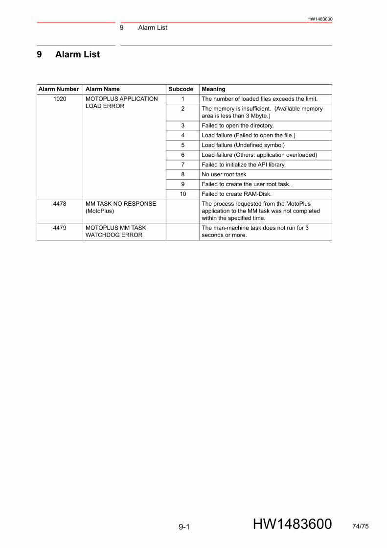
9 Alarm List
9-1
HW1483600
HW1483600
9 Alarm List
Alarm Number Alarm Name Subcode Meaning
1020 MOTOPLUS APPLICATION LOAD ERROR
1 The number of loaded files exceeds the limit.
2 The memory is insufficient. (Available memory area is less than 3 Mbyte.)
3 Failed to open the directory.
4 Load failure (Failed to open the file.)
5 Load failure (Undefined symbol)
6 Load failure (Others: application overloaded)
7 Failed to initialize the API library.
8 No user root task
9 Failed to create the user root task.
10 Failed to create RAM-Disk.
4478 MM TASK NO RESPONSE (MotoPlus)
The process requested from the MotoPlus application to the MM task was not completed within the specified time.
4479 MOTOPLUS MM TASK WATCHDOG ERROR
The man-machine task does not run for 3 seconds or more.
74/75

YRC1000 OPTIONSINSTRUCTIONSUser’s Manual For New Language Environment MotoPlus
HEAD OFFICE2-1 Kurosakishiroishi, Yahatanishi-ku, Kitakyushu 806-0004, JapanPhone +81-93-645-7703 Fax +81-93-645-7802
100 Automation Way, Miamisburg, OH 45342, U.S.A. Phone +1-937-847-6200 Fax +1-937-847-6277
YASKAWA America Inc. (Motoman Robotics Division)
Yaskawastrasse 1, 85391 Allershausen, GermanyPhone +49-8166-90-100 Fax +49-8166-90-103
YASKAWA Europe GmbH (Robotics Divsion )
Phone +82-2-784-7844 Fax +82-2-784-8495
151 Lorong Chuan, #04-02A, New Tech Park, Singapore 556741Phone +65-6282-3003 Fax +65-6289-3003
YASKAWA Electric (Singapore) PTE Ltd.
No7 Yongchang North Road, Beijing E&T Development Area,China 100176Phone +86-10-6788-2858 Fax +86-10-6788-2878
YASKAWA SHOUGANG ROBOT Co. Ltd.
#426, Udyog Vihar, Phase- IV, Gurgaon, Haryana, IndiaFax +91-124-475-8542Phone +91-124-475-8500
YASKAWA India Private Ltd. (Robotics Division)
YASKAWA Electric (China) Co., Ltd.22F, One Corporate Avenue, No.222, Hubin Road, Huangpu District, Shanghai 200021, ChinaPhone +86-21-5385-2200 Fax +86-21-5385-3299
YASKAWA Electric (Thailand) Co., Ltd.59,1st-5th Floor, Flourish Building, Soi Ratchadapisek 18,Ratchadapisek Road, Huaykwang, Bangkok 10310, THAILANDPhone +66-2-017-0099 Fax +66-2-017-0199
12F, No.207, Sec. 3, Beishin Rd., Shindian District, New Taipei City 23143, TaiwanFax +886-2-8913-1513Phone +886-2-8913-1333
YASKAWA Electric Taiwan Corporation
Secure Building-Gedung B Lantai Dasar & Lantai 1 JI. Raya Protokol Halim Perdanakusuma, Jakarta 13610, Indonesia
Fax +62-21-2982-6741Phone +62-21-2982-6470
PT. YASKAWA Electric Indonesia
Phone +46-480-417-800 Fax +46-486-414-10
YASKAWA Nordic ABVerkstadsgatan 2, Box 504 ,SE-385 25 Torsas, Sweden
35F, Three IFC, 10 Gukjegeumyung-ro, Yeongdeungpo-gu, Seoul, Korea 07326YASKAWA Electric Korea Corporation
HW1483600
C 2016 YASKAWA ELECTRIC CORPORATION
September 2018 16-09
Published by YASKAWA
MANUAL NO.
1 75/75