yueqian zhang* and herbert gross systematic design of
TRANSCRIPT
Adv. Opt. Techn. 2019; 8(5): 313–347
Review Article
Yueqian Zhang* and Herbert Gross
Systematic design of microscope objectives. Part I: System review and analysishttps://doi.org/10.1515/aot-2019-0002Received January 4, 2019; accepted March 25, 2019; previously published online May 14, 2019
Abstract: In the three connected papers, a systematic analysis and synthesis approach for microscope objectives is introduced. To subtract off the hidden assumptions in the historical development of the microscope objective lenses and extract the intrinsic lens modules, a large objective database is implemented including most of the patented systems for standardised applications. Based on the systematic analysis of the database, in Part I, a general review of the development history is given. A systematic classification method is proposed with respect to the five most significant parameters. According to the review and classification, the impacts of applications, manufacture and technology considerations are systematically ana-lysed and summarised. Details of the lens modules will be discussed in Part II, and the synthesis approach utilising the lens modules will be introduced in Part III.
Keywords: aberration correction; microscope objective; microscopy; optical design.
1 IntroductionThe microscope objective lens is the most typical high numerical aperture (NA) system, which provides a high-con-trast image with diffraction-limited resolution for various microscopy applications. The development of micro-scope objective has a long history over hundreds of years. However, because conventional microscope systems are highly standardised and objective development is strongly application-oriented, the lenses were designed with
traditional approach following the technology roadmap of a specific vendor. Therefore, the systems were developed with accumulated tremendous complexity. A systematic analysis and design approach, which decouples the impact of high NA physical nature, application impact and system assembly consideration, has been rarely reported.
Although the early age of microscope objective devel-opment has been well described in various literatures [1–5], there are only two articles reviewing modern objec-tives after 1970s, which were reported by Riesenberg in 1988 [6] and Broome in 1992 [7]. From the mid-1990s, the growing demand from fluorescence microscopy and the semiconductor industry significantly influenced the development of microscope objective. A clear review of the latest arts is still missing. In addition, design princi-ples were seldom discussed [8], and illustrative systematic synthesis approach cannot be found for high NA cases [9–11]. Last year, we have proposed a new systematic approach for microscope objective analysis and synthesis [12], which is based on 116 systems from patents. However, it only focused on the functionality of lens modules for aberration correction, without discussing the impact of application and manufacturing consideration.
‘Zu den Sachen selbst’ (back to the things themselves) is a key concept of phenomenological Epoché in Husserl’s phenomenology, where ‘Sachen’ or ‘thing’ in English refers to any phenomenon that may confront the ego in con-sciousness [13], such as a law of nature. In optical design, it is also necessary to subtract the hidden assumptions to reach the reality [14]. Concerning the growing demand of various high NA applications and the recent trend of deep learning-aided optical design, it becomes more important to operate the Epoché to efficiently utilise the experience in conventional microscope objective design. As a basic step, we have collected most of the patented microscope lenses for standardised applications. Systematic analysis was conducted with respect to three concepts: aberration correction, impact of application and considerations of manufacture and technology. For each phenomenological model in the objective design, each concept is discussed with certain Epoché.
In this paper, a historical review of the system development is given, and a systematic classification is
*Corresponding author: Yueqian Zhang, Institute of Applied Physics, Friedrich Schiller University Jena, Albert-Einstein-Str. 15, 07745 Jena, Germany, e-mail: [email protected] Herbert Gross: Institute of Applied Physics, Friedrich Schiller University Jena, Albert-Einstein-Str. 15, 07745 Jena, Germany
Open Access. © 2019 Yueqian Zhang et al., published by De Gruyter. This work is licensed under the Creative Commons Attribution- NonCommercial-NoDerivatives 4.0 License.
www.degruyter.com/aot© 2019 THOSS Media and De Gruyter
314 Y. Zhang and H. Gross: Systematic design of microscope objectives. Part I
implemented to set the basis for systematic analysis. The impacts of the most significant applications and general manufacture and technology considerations are analysed and summarised. Decoupling these effects, the detailed design principles and lens modules would be introduced in the connected paper Part II, and the system synthesis and discussion of some special techniques are included in Part III.
2 Patents collection and database setup
We have collected 448 entries from patents of the United States, Germany and Japan. Although some individual entries could also be found from Russian, Chinese and Korean patents, they are mostly designed for a specific setup, not for standardised applications. Because there is no special design principle applied, they are excluded from the database. Designed for different setups, some systems with identical structures were reported in mul-tiple patents from different countries. These systems are combined with the reference to the US patents; thus the remaining German and Japanese patents indicate that they are only patented in the corresponding countries.
Owing to their distinctive complexity, optical disk objectives and recent in vivo endoscopic microscope objectives are not considered in the patent collection. The collected entries are patented for various research and routine applications and mostly focus on the field of biomedical research and semiconductor industry. When
it comes to the system structure, reflective and catadiop-tric objectives are excluded, but objectives with diffractive optical elements (DOE) are collected to analyse the func-tionality of the DOE in system simplification.
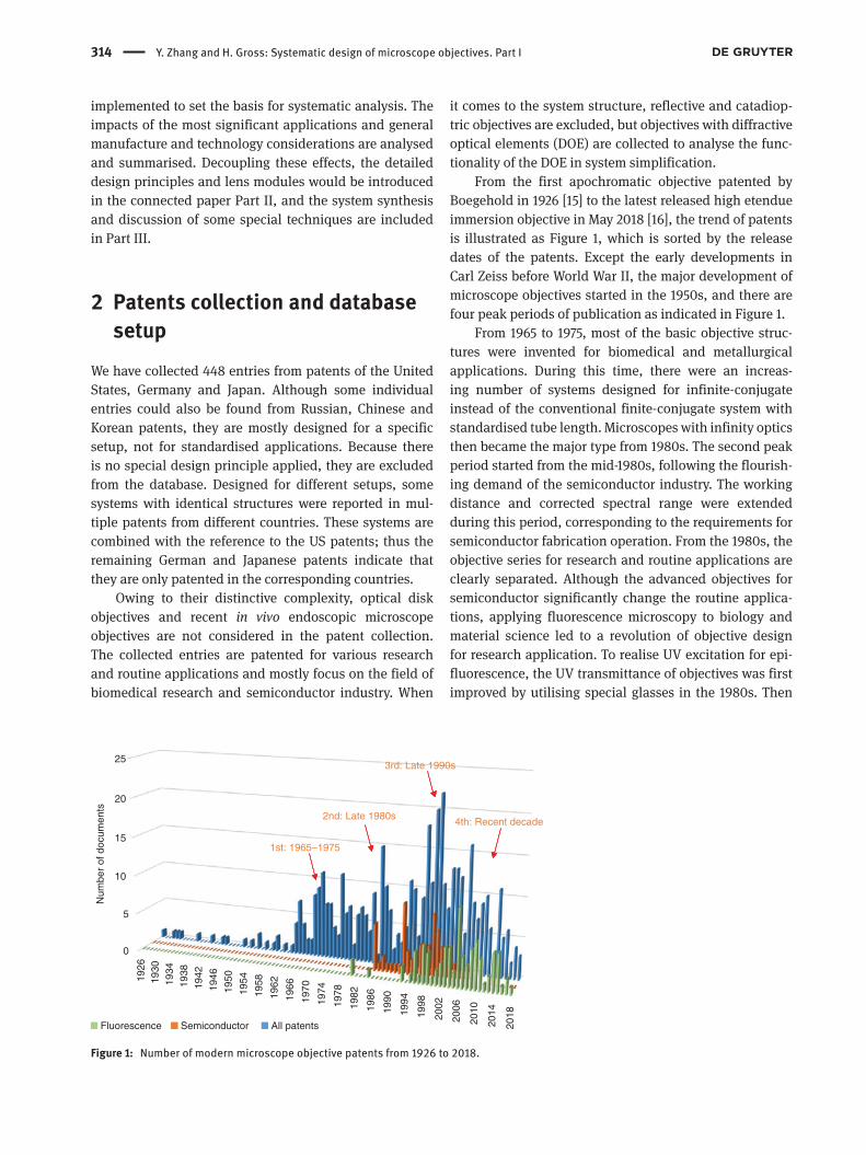
From the first apochromatic objective patented by Boegehold in 1926 [15] to the latest released high etendue immersion objective in May 2018 [16], the trend of patents is illustrated as Figure 1, which is sorted by the release dates of the patents. Except the early developments in Carl Zeiss before World War II, the major development of microscope objectives started in the 1950s, and there are four peak periods of publication as indicated in Figure 1.
From 1965 to 1975, most of the basic objective struc-tures were invented for biomedical and metallurgical applications. During this time, there were an increas-ing number of systems designed for infinite-conjugate instead of the conventional finite-conjugate system with standardised tube length. Microscopes with infinity optics then became the major type from 1980s. The second peak period started from the mid-1980s, following the flourish-ing demand of the semiconductor industry. The working distance and corrected spectral range were extended during this period, corresponding to the requirements for semiconductor fabrication operation. From the 1980s, the objective series for research and routine applications are clearly separated. Although the advanced objectives for semiconductor significantly change the routine applica-tions, applying fluorescence microscopy to biology and material science led to a revolution of objective design for research application. To realise UV excitation for epi-fluorescence, the UV transmittance of objectives was first improved by utilising special glasses in the 1980s. Then
0
5
10
15
20
25
1926
1930
1934
1938
1942
1946
1950
1954
1958
1962
1966
1970
1974
1978
1982
1986
1990
1994
1998
2002
2006
2010
2014
2018
Fluorescence Semiconductor All patents
1st: 1965–1975
2nd: Late 1980s
3rd: Late 1990s
4th: Recent decade
Num
ber
of d
ocum
ents
Figure 1: Number of modern microscope objective patents from 1926 to 2018.

Y. Zhang and H. Gross: Systematic design of microscope objectives. Part I 315
in the 1990s, various advanced objectives with excellent fluorescence contrast were further invented. Therefore, the highest peak period of microscope objective publica-tion was found around 2000, which results from the devel-opment for both the research and routine applications. There are two major reasons resulting in the recent peak period of development. For one thing, coming into the 21st century, digital sensors were well developed and widely utilised. Utilising digital imaging and postmagnification, it is possible to obtain high-resolution image with large visual field. Therefore, objectives with low/medium mag-nification and high NA are preferred instead of the high magnification objectives, to avoid the frequently cumber-some changing of objectives. In addition, an increasing number of advanced fluorescence microscopy methods were utilised, such as nonlinear microscopy (e.g. mul-tiphoton microscopy), total internal reflection fluorescent microscopy (TIRFM) and superresolution localisation microscopy. Owing to their essential requirement of high contrast, high resolution and special system parameter (spectral range, working distance, etc.), the objective structures were modified. Hence, combining these two effects, a series of objectives with highest complexity was reported in the recent decade.
To extract the lens modules or the building blocks for microscope objective design, the collected systems should be systematically analysed and compared. For system analysis, we excluded the objectives only corrected for UV or IR spectral range, which have different functionality in chromatic aberration correction. It is also notable that typically there are many embodiments included in one patent. When we build up the system database, maximum etendue objectives with each basic structure are selected. Eventually, from the remaining 373 patents, 484 systems
with different structures are built up within Zemax as a database.
The throughput of an optical system is typically repre-sented by an etendue G-value, which is defined by its NA and field of view, e.g. object height yobj:
2
objG (2y NA) .4π ⋅= (1)
The aperture size and field of view of the microscope objectives are mostly specified by the object space NA and intermediate image size (the intermediate image size is denoted by SF with the unit of millimeter in the three papers), respectively. However, because of the different arrangement of the conjugate (infinite-conjugate vs. finite conjugate) and the selection of tube lens focal lengths, etendue of objectives from different vendors cannot be compared directly. Therefore, we are using the object height, which is calculated as the intermediate image size divided by the system magnification, to evaluate the system etendue.
Sorting the systems as a function of NA and object height, the general throughput of conventional microscope objectives could be demonstrated by two boundary con-stant-etendue curves, G = 0.0243 mm2 and G = 0.9503 mm2, which are shown in Figure 2A. More than 90% of the col-lected objectives, with only 38 exceptions, locate within the area formed by these two curves. Assuming identical intermediate image size of 22 mm, these two G-values rep-resent a 50×/0.40 and a 20×/1.00 objective, respectively. The maximum etendue value of the collected systems was achieved by a 10×/0.90 objective with intermediate image size of 25 mm (SF25), which is used for virtual slide micro-scopy. When it comes to the assignees, according to Figure 2B, the four major vendors of microscope objectives,
0.0 0.2 0.4 0.6 0.8 1.0 1.2 1.4 1.6 1.8
0
5
10
15
20
25
Obj
ect h
eigh
t (m
m)
NA
G = 0.9503
G = 0.0243
DUVlithographic
projector
10x/0.90 SF25 Fujimoto USP 8350904
Max etendue G = 3.976
40%
33%
8%
4%5%
5%5%
OlympusNikonZeissLeicaAOMitutoyoOthers
A B
Figure 2: (A) The diagram of collected objective lenses as a function of numerical aperture and field size. The blue and pink curves indicate the boundary G-value of conventional microscope objectives. Position of typical DUV lithographic projectors is plotted as a reference. (B) Share of different assignees in the database.
316 Y. Zhang and H. Gross: Systematic design of microscope objectives. Part I
Olympus, Nikon, Leica and Carl Zeiss, hold 85% of all patents, but the Japanese companies patented much more than the German companies. The other two main assign-ees are American Optical Corporation (AO) and Mitutoyo. AO was the first assignee that patented a series of clear-three-group objectives with infinite-conjugate in 1970s, whereas Mitutoyo is the major assignee of long working distance objectives especially for semiconductor industry.
3 Lens evolutionTo realise the systematic sorting of the systems, it is nec-essary to review the historical development of the system structures and their corresponding applications. In this section, the first patented or the most characteristic system with each milestone structure for each milestone applica-tion is selected to illustrate the lens evolution. To demon-strate the glass selection, in all the lens layout plots within these three papers, the crown glasses are coloured with light yellow, the flint glasses are coloured with orange and the fluorites or fluorite glasses (Abbe number ν > 90) are coloured with light green. With special consideration of colour correction for wider spectral range, it is possible to cement two crown glasses or two flint glasses together. In the corresponding system layout, the cemented element is plotted with two components having the same colour.
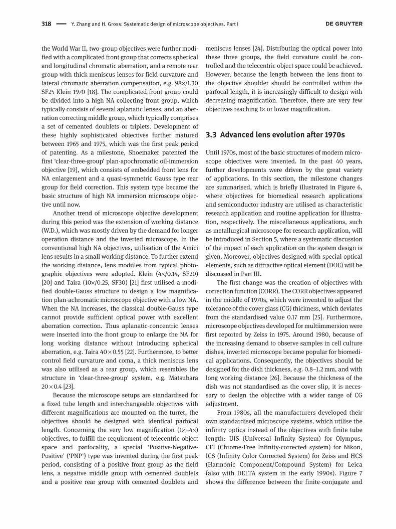
Figure 3 gives a representative microscope objec-tive structure [3]. The objective lens has a relatively sharp leading edge and a narrowed rear part with screw threads behind the objective shoulder. During the historical devel-opment of microscope objectives, two mechanical dimen-sions were standardised: the parfocal length and the thread diameter. The parfocal length is defined as the dis-tance between the object plane and the objective shoulder,
which limits the axial dimension of the objective lens. The thread diameter determines the maximum size of the exit ray bundle. Initially, microscope objectives were designed for a small etendue with only a few of elements. There-fore, these two parameters were standardised early on to be relatively small, e.g. 45 mm parfocal length and 0.8″ (20.32 mm) thread diameter. However, when the system NA and etendue are extended, the short axial dimen-sion is filled with lenses and the small thread size cannot match the large exit pupil size. Because the conventional standard significantly limits the degree of freedom for the system design, vendors have selected various larger values for their modern systems, e.g. 60 mm parfocal length and 25 mm thread diameter. Detailed summary of the parfocal length will be given in Section 4.3.3.
3.1 From Lister to Abbe
Figure 4 illustrates the early stage of the microscope objective evolution in the 19th century. Utilisation of an aplanatic lens with achromatic correction, which was first introduced by Lister in 1830 with a pair of planocon-vex cemented doublet, could be regarded as the start of modern microscope objective development. Petzval modi-fied the design in 1843 by optimising the planar surface to compensate spherical aberration, coma and astigmatism. Furthermore, because of the long separation of the two doublets, according to Petzval’s law, the field curvature could also be controlled under low aperture and small field size. It is also notable that the aperture stop was sometimes placed at the rear focal plane of the objective, forming a telecentric object space. In fact, the modified Petzval type is nowadays well known as the Lister type two-group microscope objective.
However, these two simple two-group objective types could only correct small NA (~0.25). To afford the high NA, as the next evolutionary step, Amici introduced an aplanatic-vertex lens (Amici lens) as the front lens in 1850. According to the functionality of an aplanatic lens, the NA could be enlarged by a factor of approximately n2 without introducing spherical aberration, where n is the refractive index of the lens material. Nevertheless, with the increasing NA, the field curvature of a large field becomes critical. To achieve a similar system throughput as the Lister type, the field size of the Amici type objec-tive must be reduced. Hence, the Amici type could only be used for objectives with medium magnification and medium NA, e.g. 40×/0.65 SF18. By the end of the 19th century, the success of Carl Zeiss factory achieved lots of breakthroughs in creating new lens structures. Utilising
Object plane
Thr
ead
diam
eter
Leading edge
Objective shoulder
Telecentric pupil
Figure 3: Schematic drawing of microscope objective structure including housing. For all the objectives within our database, if it is feasible, the aperture stop is always fixed at the back focal plane to realise telecentric object space.

Y. Zhang and H. Gross: Systematic design of microscope objectives. Part I 317
Lister10x/0.25
Petzval10x/0.25
Amici40x/0.65
Abbe1886
70x/1.25
Figure 4: Early stage of two-group microscope objective development in the 19th century.
Schott glasses and anomalous dispersion material, Abbe invented the first apochromatic oil immersion objective lens (70×/1.25). Until the inventions of Abbe, the funda-mental forms of two-group microscope objectives were well developed without patenting.
Apart from the development of the objective struc-ture, standard of microscope was also built up in the 19th century. The mechanical tube length was fixed as 160 mm, and the thread size of the objective was standardised as 0.8 inches by Royal Microscopical Society (RMS) (special tube lengths such as 180 and 210 mm are sometimes used by some vendors). On the contrary, the intermedi-ate image size (SF) was not standardised. Producers have different choices between 10 and 30 mm for the small-field or wide-field observation. Until now, each major microscope objective manufacturer still selects several
different intermediate sizes between 18 and 26.5 mm for their various microscope setups.
3.2 Modern lens evolution before 1980s
Development of two-group objectives continued in the first half of the 20th century. The conventional structures were patented by various companies during this period. An overview of the lens evolution before 1980s is given in Figure 5. Achieving larger field of view with excellent chromatic correction became a trend during this period, and the field curvature must be well corrected. In 1938, Boegehold first reported the well-known method for field curvature correction by utilising a thick meniscus lens in the rear group to compensate Petzval curvature [17]. After
Boegehold1938(1940)
31x/0.65
Taira1974
40x/0.55
Klein1970
98x/1.30
Matsubara1975
20x/0.40
Two to three group with field flatteing Double gauss typeLong working distance
Taira1973
10x/0.25
Shoemaker1972
100x/1.25
Embeded front lens
Gauss type rear
group
Ver
y lo
w m
agni
ficat
ion,
par
foca
l, te
lece
ntric
“PNP” TypeKlein1965
3x/0.06
Figure 5: Modern microscope objective development for field flattening and extended working distance. ‘PNP’ type very low magnification telecentric parfocal objective was also invented during the first peak period.
318 Y. Zhang and H. Gross: Systematic design of microscope objectives. Part I
the World War II, two-group objectives were further modi-fied with a complicated front group that corrects spherical and longitudinal chromatic aberration, and a remote rear group with thick meniscus lenses for field curvature and lateral chromatic aberration compensation, e.g. 98×/1.30 SF25 Klein 1970 [18]. The complicated front group could be divided into a high NA collecting front group, which typically consists of several aplanatic lenses, and an aber-ration correcting middle group, which typically comprises a set of cemented doublets or triplets. Development of these highly sophisticated objectives further matured between 1965 and 1975, which was the first peak period of patenting. As a milestone, Shoemaker patented the first ‘clear-three-group’ plan-apochromatic oil-immersion objective [19], which consists of embedded front lens for NA enlargement and a quasi-symmetric Gauss type rear group for field correction. This system type became the basic structure of high NA immersion microscope objec-tive until now.
Another trend of microscope objective development during this period was the extension of working distance (W.D.), which was mostly driven by the demand for longer operation distance and the inverted microscope. In the conventional high NA objectives, utilisation of the Amici lens results in a small working distance. To further extend the working distance, lens modules from typical photo-graphic objectives were adopted. Klein (4×/0.14, SF20) [20] and Taira (10×/0.25, SF30) [21] first utilised a modi-fied double-Gauss structure to design a low magnifica-tion plan-achromatic microscope objective with a low NA. When the NA increases, the classical double-Gauss type cannot provide sufficient optical power with excellent aberration correction. Thus aplanatic-concentric lenses were inserted into the front group to enlarge the NA for long working distance without introducing spherical aberration, e.g. Taira 40 × 0.55 [22]. Furthermore, to better control field curvature and coma, a thick meniscus lens was also utilised as a rear group, which resembles the structure in ‘clear-three-group’ system, e.g. Matsubara 20 × 0.4 [23].
Because the microscope setups are standardised for a fixed tube length and interchangeable objectives with different magnifications are mounted on the turret, the objectives should be designed with identical parfocal length. Concerning the very low magnification (1×–4×) objectives, to fulfill the requirement of telecentric object space and parfocality, a special ‘Positive-Negative- Positive’ (‘PNP’) type was invented during the first peak period, consisting of a positive front group as the field lens, a negative middle group with cemented doublets and a positive rear group with cemented doublets and
meniscus lenses [24]. Distributing the optical power into these three groups, the field curvature could be con-trolled and the telecentric object space could be achieved. However, because the length between the lens front to the objective shoulder should be controlled within the parfocal length, it is increasingly difficult to design with decreasing magnification. Therefore, there are very few objectives reaching 1× or lower magnification.
3.3 Advanced lens evolution after 1970s
Until 1970s, most of the basic structures of modern micro-scope objectives were invented. In the past 40 years, further developments were driven by the great variety of applications. In this section, the milestone changes are summarised, which is briefly illustrated in Figure 6, where objectives for biomedical research applications and semiconductor industry are utilised as characteristic research application and routine application for illustra-tion, respectively. The miscellaneous applications, such as metallurgical microscope for research application, will be introduced in Section 5, where a systematic discussion of the impact of each application on the system design is given. Moreover, objectives designed with special optical elements, such as diffractive optical element (DOE) will be discussed in Part III.
The first change was the creation of objectives with correction function (CORR). The CORR objectives appeared in the middle of 1970s, which were invented to adjust the tolerance of the cover glass (CG) thickness, which deviates from the standardised value 0.17 mm [25]. Furthermore, microscope objectives developed for multiimmersion were first reported by Zeiss in 1975. Around 1980, because of the increasing demand to observe samples in cell culture dishes, inverted microscope became popular for biomedi-cal applications. Consequently, the objectives should be designed for the dish thickness, e.g. 0.8–1.2 mm, and with long working distance [26]. Because the thickness of the dish was not standardised as the cover slip, it is neces-sary to design the objective with a wider range of CG adjustment.
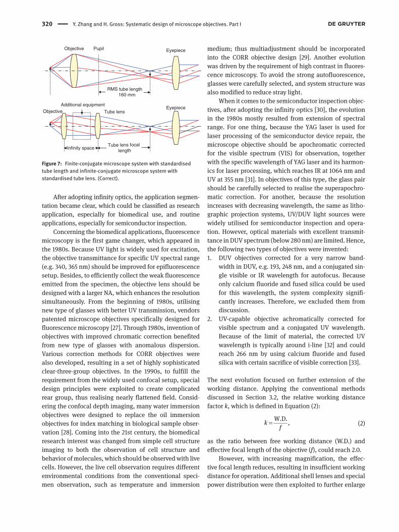
From 1980s, all the manufacturers developed their own standardised microscope systems, which utilise the infinity optics instead of the objectives with finite tube length: UIS (Universal Infinity System) for Olympus, CFI (Chrome-Free Infinity-corrected system) for Nikon, ICS (Infinity Color Corrected System) for Zeiss and HCS (Harmonic Component/Compound System) for Leica (also with DELTA system in the early 1990s). Figure 7 shows the difference between the finite-conjugate and

Y. Zhang and H. Gross: Systematic design of microscope objectives. Part I 319
infinite-conjugate system. Concerning both the incidence angle on the tube lens and the mechanical track of the whole system, the optimal focal length of the tube lens would be selected between 150 and 250 mm. The four major vendors are using 180, 200, 164.5, and 200 mm in their standardised systems, respectively. As the light path leaving the objective is collimated, the beam splitter for epi-illumination and additional equipment for con-trast methods could be inserted into the infinity space without changing the image scale or the intermediate image position. In most microscope systems, objective
lens with different magnification and NA are installed on an objective turret. When the objectives are parfocal and the focal length of the tube lens is fixed, independ-ent of the additional elements inserted into the infin-ity space, the sample-intermediate image conjugate is always fixed. Therefore, observation with different con-trast methods under different magnifications could be compared easily. Taking this advantage, it is also simple to add an epi-illumination setup into the microscope system, particularly for fluorescence microscopy with epifluorescence excitation.
1970s
1980s
Tojyo1977
60x/0.95
Yonekubo1979
20x/0.40
Kimura1985
50x/0.60Tojyo1981
10x/0.40
Kenno1987
50x/0.501990s
2000s
2010sKasahara
2013100x/1.70
Arisawa2000
200x/0.62
Abe SF162018
10.6x/1.35
Fujimoto SF252018
10x/0.90
Arisawa1992
50x/0.50
Kashima1993
100x/0.85
Chuang2006
100x/0.80
Saito1990
100x/0.80
Saito1996
60x/1.15
Yamaguchi1999
60x/0.85
Shi2006
63x/1.20(1.30)
Wartmann2014
40x/1.30
Shi2007
100x/1.25
Objective with correction(CG adjust)
Inverted microscope
Widely use of infinite-corrected system
Application segmentation
Research applicationesp. biomedical research
Fluorescence microscopy (UV trans)
Improved chromatic correctionand CG adjust
Improved field flattening and indexmatching for confocal microscopy
Reduced autofluorescence for betterfluoresence observation
Live cell moleculeobservation
Multi-adjust
Multi-photon, IRDIC (UV-IR)
Advanced digital microscopy e.g. vitual slides
IR objectives...
Low cost
TIRF
Cata systems...Advanced aberration correction
Extended super-long working distance
DUV objectives...Wide spectral range (UV-IR)superapochromatic correction
Routine applicationesp. semiconductor industry
Figure 6: Advanced modern microscope objective development corresponding to application segmentation.
320 Y. Zhang and H. Gross: Systematic design of microscope objectives. Part I
After adopting infinity optics, the application segmen-tation became clear, which could be classified as research application, especially for biomedical use, and routine applications, especially for semiconductor inspection.
Concerning the biomedical applications, fluorescence microscopy is the first game changer, which appeared in the 1980s. Because UV light is widely used for excitation, the objective transmittance for specific UV spectral range (e.g. 340, 365 nm) should be improved for epifluorescence setup. Besides, to efficiently collect the weak fluorescence emitted from the specimen, the objective lens should be designed with a larger NA, which enhances the resolution simultaneously. From the beginning of 1980s, utilising new type of glasses with better UV transmission, vendors patented microscope objectives specifically designed for fluorescence microscopy [27]. Through 1980s, invention of objectives with improved chromatic correction benefited from new type of glasses with anomalous dispersion. Various correction methods for CORR objectives were also developed, resulting in a set of highly sophisticated clear-three-group objectives. In the 1990s, to fulfill the requirement from the widely used confocal setup, special design principles were exploited to create complicated rear group, thus realising nearly flattened field. Consid-ering the confocal depth imaging, many water immersion objectives were designed to replace the oil immersion objectives for index matching in biological sample obser-vation [28]. Coming into the 21st century, the biomedical research interest was changed from simple cell structure imaging to both the observation of cell structure and behavior of molecules, which should be observed with live cells. However, the live cell observation requires different environmental conditions from the conventional speci-men observation, such as temperature and immersion
medium; thus multiadjustment should be incorporated into the CORR objective design [29]. Another evolution was driven by the requirement of high contrast in fluores-cence microscopy. To avoid the strong autofluorescence, glasses were carefully selected, and system structure was also modified to reduce stray light.
When it comes to the semiconductor inspection objec-tives, after adopting the infinity optics [30], the evolution in the 1980s mostly resulted from extension of spectral range. For one thing, because the YAG laser is used for laser processing of the semiconductor device repair, the microscope objective should be apochromatic corrected for the visible spectrum (VIS) for observation, together with the specific wavelength of YAG laser and its harmon-ics for laser processing, which reaches IR at 1064 nm and UV at 355 nm [31]. In objectives of this type, the glass pair should be carefully selected to realise the superapochro-matic correction. For another, because the resolution increases with decreasing wavelength, the same as litho-graphic projection systems, UV/DUV light sources were widely utilised for semiconductor inspection and opera-tion. However, optical materials with excellent transmit-tance in DUV spectrum (below 280 nm) are limited. Hence, the following two types of objectives were invented:1. DUV objectives corrected for a very narrow band-
width in DUV, e.g. 193, 248 nm, and a conjugated sin-gle visible or IR wavelength for autofocus. Because only calcium fluoride and fused silica could be used for this wavelength, the system complexity signifi-cantly increases. Therefore, we excluded them from discussion.
2. UV-capable objective achromatically corrected for visible spectrum and a conjugated UV wavelength. Because of the limit of material, the corrected UV wavelength is typically around i-line [32] and could reach 266 nm by using calcium fluoride and fused silica with certain sacrifice of visible correction [33].
The next evolution focused on further extension of the working distance. Applying the conventional methods discussed in Section 3.2, the relative working distance factor k, which is defined in Equation (2):
W.D. ,kf
= (2)
as the ratio between free working distance (W.D.) and effective focal length of the objective (f), could reach 2.0.
However, with increasing magnification, the effec-tive focal length reduces, resulting in insufficient working distance for operation. Additional shell lenses and special power distribution were then exploited to further enlarge
Objective Eyepiece
RMS tube length160 mm
ObjectiveEyepiece
Tube lens focallengthInfinity space
Tube lens
Additional equipment
Pupil
Figure 7: Finite-conjugate microscope system with standardised tube length and infinite-conjugate microscope system with standardised tube lens. (Correct).
Y. Zhang and H. Gross: Systematic design of microscope objectives. Part I 321
the working distance. For some 200× objectives, the rela-tive working distance could exceed 13.0 [34]. After 2000, catadioptric layouts are used for semiconductor objectives to realise extreme aperture and field size. Furthermore, many designs focused on advanced field and chromatic correction, including chromatic variation of coma, to gen-erate uniform resolution over the full field [35]. It is worth mentioning that modern microscopy technologies such as fluorescence microscopy and confocal microscopy are also applied to semiconductor microscopy through its development from 1990s. They utilised the design prin-ciples from corresponding microscope objectives for bio-medical application.
In the recent decade, the latest development of micro-scope objectives for biomedical use mostly focused on the application of advanced fluorescence microscopy. It is notable that many design principles utilised for semi-conductor applications were also adopted. For instance, in multiphoton microscopy, IR light is used for excita-tion and the harmonic fluorescence is generated at UV and visible range. Under the epi-illumination setup, the microscope objective must be superapochromatic corrected from UV to IR [36], where the glass selection method is similar to what is used in superapochromatic semiconductor objective. The next trend of the advanced microscope objective design is to fulfill the requirements from the superresolution methods. TIRF microscopy is particularly considered because of its requirement of system NA larger than 1.38. Utilising special immersion oil, the 100× objective could reach extreme NA of 1.70 [37]. Other objectives designed for popular localization microscopy methods were also proposed by the vendors. Moreover, based on the development of digital sensor, objective with high NA but low magnification is of interest to achieve high resolution with wide field, particularly for virtual slide microscopy. However, the abovementioned objectives should be corrected for far larger etendue than the conventional systems, which could be found as the dots above the constant-etendue curve G = 0.9503 mm2 in Figure 2A. Their structures cannot be simply divided into clear-three-groups. Many of the utilised special structures significantly correct the induced higher order aberrations but suffer from critical sensitivity. Another orientation in the recent decade is to generate various new structures that ensure better system tolerance for low cost micro-scope objective lens.
In recent years, new microscope objectives with highest etendue have been patented for virtual slide microscopy. Some systems do not only realise high NA under low magnification, but also eliminate vignetting [38], which is similar to the advanced semiconductor
objective. However, as a consequence, the parfocal length and thread diameter cannot be controlled within the con-ventional value.
Generally speaking, lots of common design princi-ples are applied to both the current microscope objec-tives for biomedical use and semiconductor industry. Because these high NA systems nearly reached the bound-ary etendue, the application-based differences are over-whelmed by the physical similarity.
4 System classification and important parameters
To analyse the objectives and summarise the lens modules, it is necessary to classify the collected objec-tives into several classes and compare the structure of individual objective lens concerning their functional-ity resulted from aberration correction, application and the considerations of manufacture and technology. The most conventional classification method is based on the system performance, which focused on the correction of chromatic aberration and field curvature. Correction of these two most important aberrations could partly indi-cate the complexity of the objective; however, because a systematic sorting of system NA and field, namely etendue, is missing, a general systematic classification of all the objectives cannot be achieved. It is only possible to analyse the impact of aberration on the lens modules by combining the etendue classification and conventional performance classification.
4.1 System classification based on performance
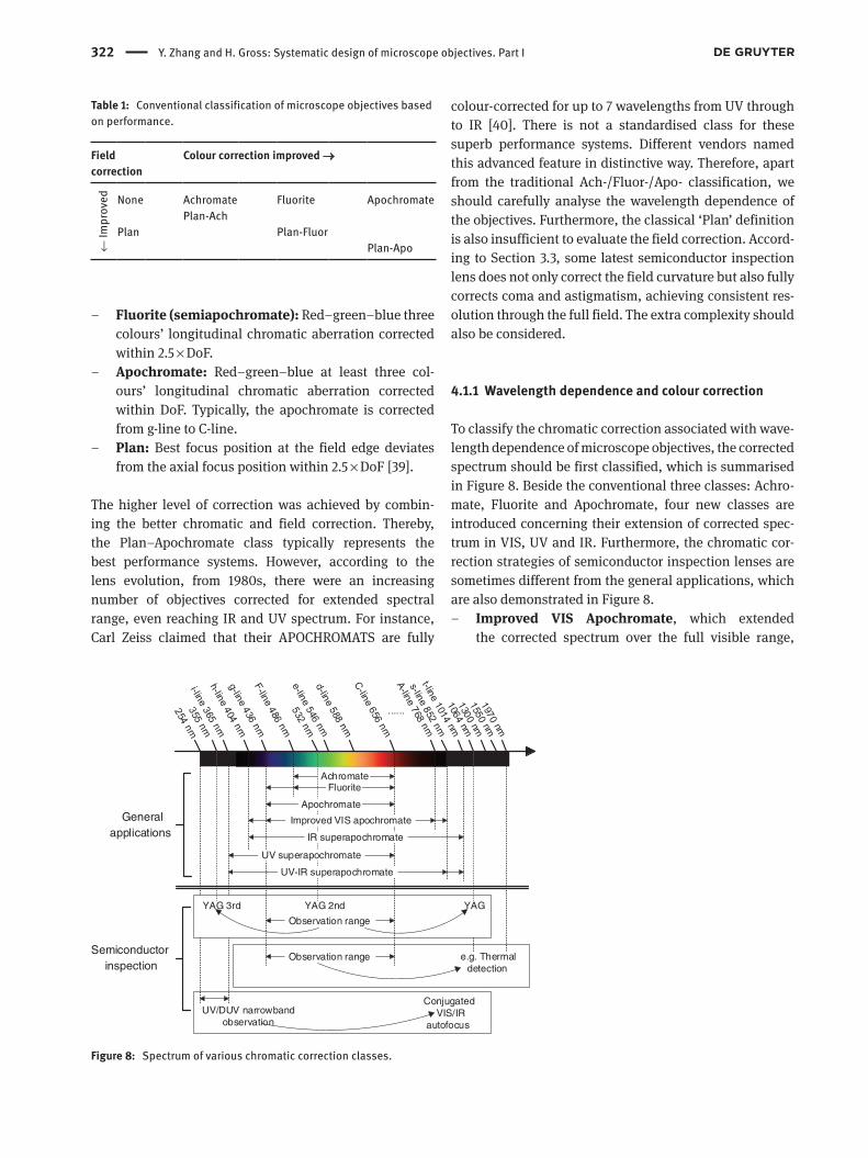
The most traditional approach to classify microscope objectives is to define quality classes based on their lon-gitudinal chromatic correction and field flatness, which is briefly demonstrated in Table 1. The conventional classes were defined according to their correction with respect to the depth of focus (DoF), which is defined by nλ/NA2, where λ is the central wavelength and n is the refractive index of the immersion medium.
– Achromate: Red–blue two colours’ longitudinal chromatic aberration corrected within 2 × DoF. Typi-cally, the F-line and C-line, or F′-line and C′-line are corrected. The secondary spectrum, e.g. C′-e and F′-e, are also limited within 1.5 × DoF. (F-C is considered instead of F′-C′ in following discussion.)
322 Y. Zhang and H. Gross: Systematic design of microscope objectives. Part I
– Fluorite (semiapochromate): Red–green–blue three colours’ longitudinal chromatic aberration corrected within 2.5 × DoF.
– Apochromate: Red–green–blue at least three col-ours’ longitudinal chromatic aberration corrected within DoF. Typically, the apochromate is corrected from g-line to C-line.
– Plan: Best focus position at the field edge deviates from the axial focus position within 2.5 × DoF [39].
The higher level of correction was achieved by combin-ing the better chromatic and field correction. Thereby, the Plan–Apochromate class typically represents the best performance systems. However, according to the lens evolution, from 1980s, there were an increasing number of objectives corrected for extended spectral range, even reaching IR and UV spectrum. For instance, Carl Zeiss claimed that their APOCHROMATS are fully
colour-corrected for up to 7 wavelengths from UV through to IR [40]. There is not a standardised class for these superb performance systems. Different vendors named this advanced feature in distinctive way. Therefore, apart from the traditional Ach-/Fluor-/Apo- classification, we should carefully analyse the wavelength dependence of the objectives. Furthermore, the classical ‘Plan’ definition is also insufficient to evaluate the field correction. Accord-ing to Section 3.3, some latest semiconductor inspection lens does not only correct the field curvature but also fully corrects coma and astigmatism, achieving consistent res-olution through the full field. The extra complexity should also be considered.
4.1.1 Wavelength dependence and colour correction
To classify the chromatic correction associated with wave-length dependence of microscope objectives, the corrected spectrum should be first classified, which is summarised in Figure 8. Beside the conventional three classes: Achro-mate, Fluorite and Apochromate, four new classes are introduced concerning their extension of corrected spec-trum in VIS, UV and IR. Furthermore, the chromatic cor-rection strategies of semiconductor inspection lenses are sometimes different from the general applications, which are also demonstrated in Figure 8.
– Improved VIS Apochromate, which extended the corrected spectrum over the full visible range,
Table 1: Conventional classification of microscope objectives based on performance.
Field correction
Colour correction improved →
← Im
prov
ed None Achromate Fluorite ApochromatePlan-Ach
Plan Plan-Fluor Plan-Apo
......
General applications
Semiconductorinspection
AchromateFluorite
Apochromate
IR superapochromate
Improved VIS apochromate
UV superapochromate
UV-IR superapochromate
YAGYAG 2ndYAG 3rd
Observation range
UV/DUV narrowbandobservation
Conjugated VIS/IR
autofocus
Observation range e.g. Thermal detection
Figure 8: Spectrum of various chromatic correction classes.
Y. Zhang and H. Gross: Systematic design of microscope objectives. Part I 323
typically corrects longitudinal chromatic aberra-tion from g-line to A-line. In some special examples, the corrected spectrum could be further extended to h-line approaching NUV and s-line reaching NIR.
– IR Superapochromate extends the corrected spec-trum to t-line, which is mostly required by mul-tiphoton microscopy and IRDIC applications. It is notable that in the recent Raman microscopy, IR superapochromatic correction from the VIS to SWIR around 2000 nm is also required.
– UV Superapochromate maintains full-spectrum correction in NUV and visible range. It is sometimes well corrected from i-line to C-line, which assures the common focus of UV excitation and visible observa-tion. This class is also widely used for semiconductor inspection system.
– UV-IR Superapochromate is the state-of-the-art chro-matic correction class, which could be corrected from i-line to t-line. Only a few objectives could reach this class, and they are used for multiphoton microscopy.
The classes correct chromatic aberration through a certain spectral range. However, when it comes to the semicon-ductor inspection systems, despite the visible range for observation, correction of specific wavelengths in UV and IR range, instead of a full spectrum correction, is consid-ered according to applications.
– YAG laser (1064 nm) and its harmonics are widely used for semiconductor repairing. To assure the repairing, laser beam is focused onto the observation plane, achromatism of the visible range (including YAG second harmonic 532 nm) and 1064 nm and/or third harmonic 355 nm should be realised.
– Longer wavelengths in NIR and SWIR, such as 1300, 1550, and 1970 nm, are often used to test the thermal behavior of high frequency circuit.
– UV/DUV observation is mostly used in the modern semiconductor industry instead of the traditional vis-ible observation, because of the higher resolution. Because of the limit choice of materials, which has good transmittance in DUV, this type objective could only be achromatically corrected for a narrowband of spectrum. However, the objective should also be cor-rected for a conjugated wavelength in visible or IR range, which is used for autofocusing. Because the correction of this type objective is different from the conventional broadband system, as we mentioned in Section 3.3, they are excluded from discussion.
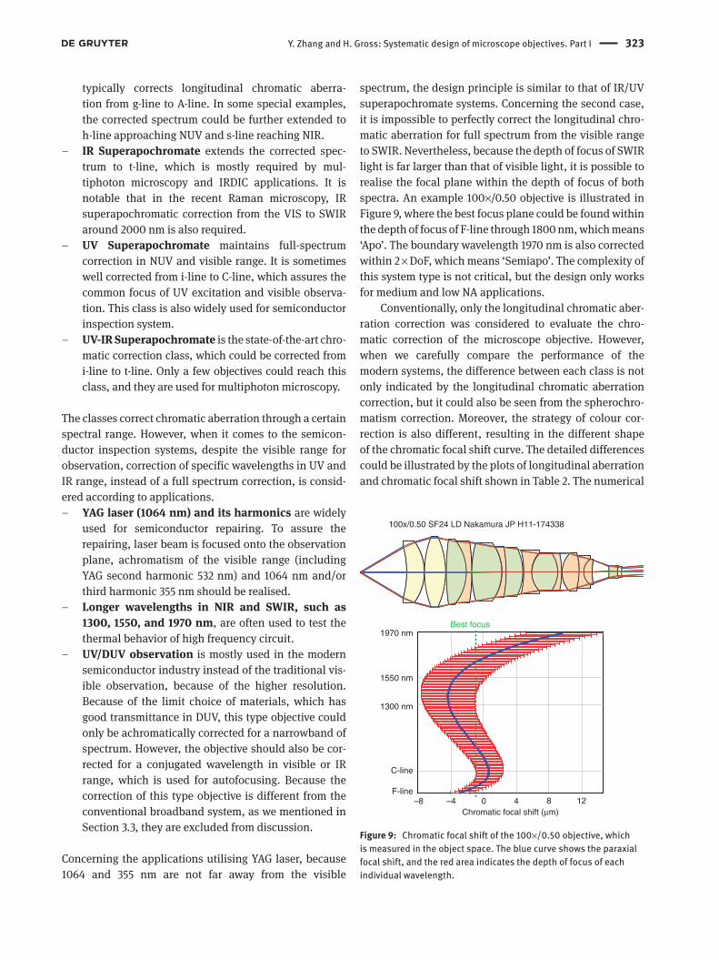
Concerning the applications utilising YAG laser, because 1064 and 355 nm are not far away from the visible
spectrum, the design principle is similar to that of IR/UV superapochromate systems. Concerning the second case, it is impossible to perfectly correct the longitudinal chro-matic aberration for full spectrum from the visible range to SWIR. Nevertheless, because the depth of focus of SWIR light is far larger than that of visible light, it is possible to realise the focal plane within the depth of focus of both spectra. An example 100×/0.50 objective is illustrated in Figure 9, where the best focus plane could be found within the depth of focus of F-line through 1800 nm, which means ‘Apo’. The boundary wavelength 1970 nm is also corrected within 2 × DoF, which means ‘Semiapo’. The complexity of this system type is not critical, but the design only works for medium and low NA applications.
Conventionally, only the longitudinal chromatic aber-ration correction was considered to evaluate the chro-matic correction of the microscope objective. However, when we carefully compare the performance of the modern systems, the difference between each class is not only indicated by the longitudinal chromatic aberration correction, but it could also be seen from the spherochro-matism correction. Moreover, the strategy of colour cor-rection is also different, resulting in the different shape of the chromatic focal shift curve. The detailed differences could be illustrated by the plots of longitudinal aberration and chromatic focal shift shown in Table 2. The numerical
1970 nm
C-line
F-line–8 –4 0 4 8 12
Chromatic focal shift (µm)
1550 nm
1300 nm
100x/0.50 SF24 LD Nakamura JP H11-174338
Best focus
Figure 9: Chromatic focal shift of the 100×/0.50 objective, which is measured in the object space. The blue curve shows the paraxial focal shift, and the red area indicates the depth of focus of each individual wavelength.
324 Y. Zhang and H. Gross: Systematic design of microscope objectives. Part I
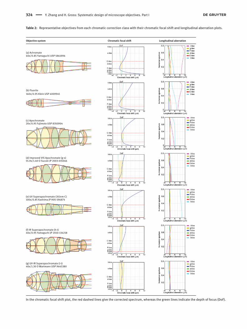
Table 2: Representative objectives from each chromatic correction class with their chromatic focal shift and longitudinal aberration plots.
Longitudinal aberrationChromatic focal shi� Objective system
(a) Achromate 60x/0.85 Yamaguchi USP 5861996
(b) Fluorite 160x/0.95 Klein USP 4009945
(c) Apochromate 20x/0.95 Fujimoto USP 8350904
(d) Improved VIS Apochromate (g-s) 55.9x/1.40 O Suzuki JP 2003-015046
(e) UV Superapochromate (351nm-C) 100x/0.85 Kashima JP H05-196874
(f) IR Superapochromate (h-t) 40x/0.95 Yamaguchi JP 2010-134218
(g) UV-IR Superapochromate (i-t) 40x/1.30 O Wartmann USP 9645380
In the chromatic focal shift plot, the red dashed lines give the corrected spectrum, whereas the green lines indicate the depth of focus (DoF).

Y. Zhang and H. Gross: Systematic design of microscope objectives. Part I 325
aperture of the selected systems is narrowed down to 0.8, and the longitudinal aberration is calculated in the object space. Thereby, identical depth of focus (DoF) could be used as a reference for comparison. For instance, at the central wavelength d-line, it is DoF = 0.918 μm for dry objective and DoF = 1.392 μm for oil immersion objective.
Concerning the conventional Achromate, Fluorite and Apochromate from class (a) to class (c), based on the basic achromatism principle, typically the chromatic focal shift curve only has one inflection point within the corrected spectrum. The slope around the inflection point, as well as saddle point, is relatively small; thus the chromatic focal shift from g-line to C-line or F-line to C-line could be controlled within 1 × ~ 2.5 × DoF. For some advanced Apochromate objectives, such as the example class (c) system, utilising special glass combinations, the area around the saddle point could be corrected rather flat. Consequently, the maximum chromatic focal shift is only half of the DoF. By comparing the longitudinal aber-ration curves, typically there is a large residual sphero-chromatism in the objectives of Achromate and Fluorite class. But when it comes to the Apochromate, both the paraxial chromatic error (longitudinal chromatic aberra-tion) and the chromatic aberration at the full aperture are well corrected, which means that the spherochromatism is removed.
When the corrected spectrum is extended to the UV and/or IR range, the longitudinal aberration should be corrected with at least two inflection points on the chromatic focal shift curve. The class (d) improved VIS Apochromate 55.9×/1.40 objective has three inflection points. The chromatic focal shift is therefore very flat and controlled within the DoF through the full spectrum. The class (e) UV superapochromate only considers the short wavelength side; three saddle points could be found from i-line to C-line, which utilises glasses with specific blue side partial dispersion. However, because the red side is not controlled, the focus of the wavelength above C-line
is shifted significantly. When it comes to the class (f) system, only the chromatic focal shift in the visible range is apochromatic corrected within the DoF. The correc-tion of C-line to t-line, although takes the advantage of DoF enlargement of long wavelength, only realises ‘Fluo-rite’ level correction. As the state-of-the-art, the class (g) system selects glasses with rather equivalent partial dis-persion in blue side and red side. Hence, the two saddle points are found in NIR and NUV, and the general curve is flat. Consequently, the chromatic focal shift from i-line to t-line is controlled within the DoF. Comparing the examples from class (d) to class (g), they could be always classified as ‘Apochromate’ according to conventional definition. However, their exact correction of the bound-ary wavelength might be distinctive. The difference mostly results from glass selection. After this careful classifica-tion, the glass selection strategies should be further ana-lysed and discussed in Part II.
The high-performance objectives above the Apochro-mate class (c) mostly correct spherochromatism at the full aperture. Some extreme cases even correct the sphero-chromatism for all the aperture zones, such as the system (d). This advanced feature is useful in the objective with iris and the application utilising laser with apodization. Under these circumstances, although the effective NA is smaller than the designed value, nearly identical longitu-dinal correction could be maintained.
4.1.2 Field correction
In the conventional classification based on performance, field correction level was basically classified according to their field curvature correction. Apart from field curvature correction, in high-performance systems, correction of other field aberrations, especially coma, should also be considered. Therefore, the field correction could be clas-sified into the following seven classes, shown in Table 3.
Table 3: Seven classes of field correction level of modern microscope objectives.
Field curvature Field aberration NA Etendue
Non-plan (class 1) No correction No correction Arbitrary ArbitraryPlan Class 2 Corrected Corrected Low Medium/low Class 3 Corrected Not well corrected High Medium/low Class 4 Corrected Corrected with vignetting High Medium/low Class 5 Corrected Corrected without vignetting High Medium/low Class 6 Corrected Corrected with vignetting High High Class 7 Corrected Corrected without vignetting High High
326 Y. Zhang and H. Gross: Systematic design of microscope objectives. Part I
Owing to the small field, coma and astigmatism in low NA systems are usually not critical; thus they are well corrected in the Plan objective (class 2). However, because the primary transverse coma increases linearly with field size and quadratically with NA, it would be tremendous at the boundary field of high NA system. Some high NA systems only utilise a small field with corrected field cur-vature and sagittal coma to fulfill isoplanatism. Although the tangential coma is not well corrected, because of the small field, it is still acceptable (class 3). When it comes to the high NA system with relatively large field (high mag-nification system with medium etendue), vignetting is a useful tool to control the field deviation by shrinking the effective NA of the boundary field (class 4). Coma could also be well corrected without vignetting, but special lens modules must be used especially in the rear group, resulting in enormous complexity (class 5). According to Section 3.3, microscope objectives with extremely high etendue were invented recently for virtual slides applica-tion. Utilising similar intermediate image size (SF20-30), the magnification is very low (10×—20×) and the NA is extremely high (dry 0.9–0.95, oil immersion 1.40–1.45). Consequently, with standardised infinity optics, the exit pupil size is 5–10 times larger than that of high magnifi-cation high NA systems. Hence, in class 6 systems, lens modules in class 5 must be utilised, and the vignetting is inevitable. As the state-of-the-art (class 7), in the high etendue system, field aberration could also be fully cor-rected without vignetting. However, the dimension of the objective is enlarged, and/or the standardised infinity optics is abandoned. The representative systems of these seven classes and their field performance are shown in Table 4. All the systems are apochromatic corrected from g-line to C-line. All the transverse aberrations are calcu-lated for the whole system, which is a combination of the objective and its tube lens.
According to the transverse aberration fans of the axial field, all the systems are nearly perfectly corrected for spherical aberration and longitudinal chromatic aber-ration. In the class 1 system (a), only the rear cemented meniscus triplet compensates the field curvature; thus the positive power is still too strong to generate negative Petzval curvature. As a result, the focal shift of the edge field is approximately 5 × DoF, two times larger than the ‘Plan’ limit. The system also suffers from large amount of astigmatism. However, because the cemented menis-cus triplet contributes a lot to coma compensation, with a little vignetting, although the field curvature is large, the resolution of the off-axial field is acceptable. The class 2 system (b) utilised the double-Gauss structure. The field curvature could be compensated by the meniscus lenses,
and coma is also well controlled by the quasi-symmetric layout. Adopted from photographic objective design, the double-Gauss type is useful in working distance exten-sion and field correction, but it only works for the low NA applications. The field curvature of class 3 system (c) is perfectly corrected for very small object diameter of 0.066 mm. Coma of F-line and d-line are also controlled well for this small field. However, the objective suffers from chromatic variation of coma, resulting in the tremen-dous coma of g-line and C-line. The class 4 system (d) is a typical high magnification high NA objective, with low etendue G = 0.044 mm2. The field curvature is corrected perfectly, and 20% vignetting was introduced to cut off the exploding coma at the edge field. On the contrary, the class 5 system (e) is designed for identical magnification and NA as (d) but with larger field. Comparing the rear part of these two systems, the system (e) did not use the popular Gauss type rear group. The thick positive lens forms a special air lens together with the following strong negative lens, which compensates field curvature and cor-rects coma simultaneously. System (f) and system (g) were invented for virtual slides application, with extremely high etendue Gf = 3.976 and Gg = 3.715 mm2, respectively. The system (f) is designed for standardised infinity optics and with parfocal length of 90 mm. The chief ray height at the rear group is large, which induced coma, and the vignet-ting of the off-axial fields is introduced by both the first and last cemented meniscus doublet as field diaphragms. However, according to the transverse aberration plot, even if 20% vignetting is utilised, coma rises dramatically at the boundary aperture. Field curvature correction is also hampered. Although the best image shell still lies within 2.5 × DoF, because of the large astigmatism, the tangential shift exceeds the limit. In the state-of-the-art system (g), all the field aberrations are well controlled. Nevertheless, the parfocal length is sacrificed. The distance from the object to the objective shoulder is approximately 300 mm, far larger than the standardised parfocal length from 45 to 105 mm. Furthermore, the diameter of the objective exceeds 100 mm, which is also five times larger than the typical diameter of NA = 1.45 objectives.
Transverse chromatic aberration (lateral colour) should also be considered when we evaluate the perfor-mance of field correction. Taking the advantage of the infinity optics, the lateral colour is usually well corrected in modern Plan-Apochromates. However, the vendors have different strategies in correcting lateral colour. Nikon and Olympus fully correct lateral colour in both objective and tube lens. Carl Zeiss leaves 1.5% lateral colour in the objective, which should be compensated by the tube lens. Leica follows a similar strategy but

Y. Zhang and H. Gross: Systematic design of microscope objectives. Part I 327
Table 4: Representative objectives from each field correction class with their field curvature and transverse aberration fan plots.
Transverse aberrationField curvatureObjective system
(a) Class 1 100x/1.35 O SF20 Goto USP 3912378
(b) Class 2 20x/0.40 SF29 Tojyo USP 4232941
(c) Class 3 100x/1.65 O SF6.6 Suzuki USP 5659425
(d) Class 4 100x/0.95 SF20 Saito USP 6188514
*Rear cemented doublet with two di erent flint glasses
(e) Class 5 100x/0.95 SF25 Matthae DE 10316415
*Cemented quartet with two di erent crown glasses cemented together
(f) Class 6 10x/0.90 SF25 Fujimoto USP 8350904
(g) Class 7 20x/1.45 SF30 Abe USP 9746658
Field curvature is plotted for central wavelength d-line. In the plot, the S stands for sagittal focal shift and the T represents the tangential focal shift. According to different definition, the best image shell could be found between the sagittal shell and tangential shell. Except Class 2, where the DoF is very large under low NA, 2.5 × DoF is shown as the reference to evaluate the level of field curvature correction.
328 Y. Zhang and H. Gross: Systematic design of microscope objectives. Part I
sometimes with additional compensation in eyepiece, which idea is also utilised in field curvature compensa-tion [41]. The different strategies were mostly originated from their correction strategies before the introduction of infinity optics. Without the help of tube lens, it was dif-ficult to correct lateral colour, whereas the correction of other aberrations is realised simultaneously. It was dis-covered very early that lateral colour and astigmatism are best corrected by delegating correction work to the objectives and eyepieces [42]. Before 1980s, only Nikon corrects lateral colour in the objective. The other vendors compensate it by the eyepiece. In the modern infinity systems, Leica and Carl Zeiss transferred the compensa-tion from eyepieces to tube lens, but Olympus turned to Nikon’s philosophy.
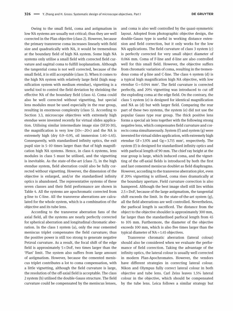
4.2 System classification based on etendue
In addition to the above classification based on perfor-mance, to analyse the lens modules, it is also necessary to further classify the systems based on NA and field size, which mostly determine the system complexity. According to the NA vs. field plot in Figure 2A, the general behavior of microscope objectives could be seen; however, the different complexity of structures corresponding to different correc-tion level cannot be distinguished. The systems could be further classified into six zones, demonstrated in Figure 10, which is modified from the former 5-zone classification [12].
– Zone 1: typical ach/apochromatic two-group systems. – Zone 2: typical Plan-ach/apochromatic clear-three-
group systems. – Zone 3: novel three-group systems with special correc-
tion lens modules.
– Zone 4: systems with extremely high NA or etendue, which sacrifice other system parameters, such as par-focal length and immersion liquid type.
– Zone 5: very low magnification parfocal telecentric systems.
– Zone 6: very high magnification systems.
There are three solid boundaries in Figure 10: (a) magni-fication of 4, (b) magnification of 100 and (c) NA of 1.5, which defines Zone 5, Zone 6 and partly defined Zone 4, respectively. Below the boundary (a), nearly all the Zone 5 systems are designed with ‘PNP’ structure, which was introduced in Figure 5, to fulfill the requirement of parfo-cality and telecentric object space. Concerning the Zone 6, only with few total internal reflection microscopy (TIRF) objectives as exceptions, most of the very high magnifi-cation systems are designed with long working distance for semiconductor-related or metallurgical applications. Additional complexity has been introduced to control the more severe chromatic aberration resulted from the reduc-ing focal length and increasing working distance. The design principles utilised in most of the Zone 6 systems are similar. The boundary condition (c) gives the limit of normal oil immersion, under which circumstance the oil index is typically around 1.515 at d-line. To realise the extremely high NA (state-of-the-art 100×/1.70), special oil must be used. For instance, the oil with d-line refractive index 1.78035 is used by Olympus (100×/1.65–1.70) [37, 43], and 1.80914 is used by Nikon (100×/1.65–1.67) [44, 45].
Most of the conventional microscope objectives, which hold 86% share in our database, are classified into Zone 1, Zone 2, and Zone 3. On the semilog coordi-nate in Figure 10, these zones are defined by four lines, which could relatively represent the etendue. With respect
1 10 100
NA
Magnification
0.0
0.2
0.4
0.6
0.8
1.0
1.2
1.4
1.6
1.8
0.05 2 4 20 40 60 250
Limit of normal oil immersion
Zone 1
Zone 2
Zone 3
Zone 4
Zone 5
Zone 6
Figure 10: 6-zone classification of microscope objectives based on etendue.
Y. Zhang and H. Gross: Systematic design of microscope objectives. Part I 329
to 22 mm intermediate image diameter, the four lines approximately represent G = 0.025 mm2, G = 0.051 mm2, G = 0.086 mm2 and G = 0.950 mm2. In each zone, most of the systems are designed with similar structural complex-ity from basic two groups to sophisticated three groups. In Zone 4, except the extremely high NA region defined by the NA = 1.5 boundary, the other systems have extremely large etendue, which are also the exceptional systems in Figure 2A.
4.3 Other important parameters
Based on the classification introduced in Sections 4.1 and 4.2, during our modular analysis, we first focus on an etendue zone and then pick up the systems with identical or comparable colour correction class and field correction class to investigate the structural complexity. However, beside these three factors, which mostly determine the objective structure, there are three other important parameters that influence the complexity of objective: the free working distance, CORR function and parfocal length. Furthermore, the pupil fixation is also necessary to be considered, which determines the telecentricity and is important for microscope systems applying contrast methods.
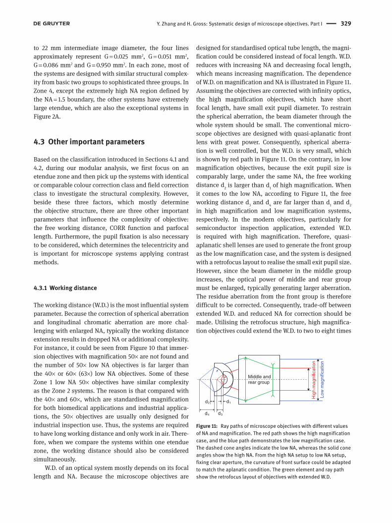
4.3.1 Working distance
The working distance (W.D.) is the most influential system parameter. Because the correction of spherical aberration and longitudinal chromatic aberration are more chal-lenging with enlarged NA, typically the working distance extension results in dropped NA or additional complexity. For instance, it could be seen from Figure 10 that immer-sion objectives with magnification 50× are not found and the number of 50× low NA objectives is far larger than the 40× or 60× (63×) low NA objectives. Some of these Zone 1 low NA 50× objectives have similar complexity as the Zone 2 systems. The reason is that compared with the 40× and 60×, which are standardised magnification for both biomedical applications and industrial applica-tions, the 50× objectives are usually only designed for industrial inspection use. Thus, the systems are required to have long working distance and only work in air. There-fore, when we compare the systems within one etendue zone, the working distance should also be considered simultaneously.
W.D. of an optical system mostly depends on its focal length and NA. Because the microscope objectives are
designed for standardised optical tube length, the magni-fication could be considered instead of focal length. W.D. reduces with increasing NA and decreasing focal length, which means increasing magnification. The dependence of W.D. on magnification and NA is illustrated in Figure 11. Assuming the objectives are corrected with infinity optics, the high magnification objectives, which have short focal length, have small exit pupil diameter. To restrain the spherical aberration, the beam diameter through the whole system should be small. The conventional micro-scope objectives are designed with quasi-aplanatic front lens with great power. Consequently, spherical aberra-tion is well controlled, but the W.D. is very small, which is shown by red path in Figure 11. On the contrary, in low magnification objectives, because the exit pupil size is comparably large, under the same NA, the free working distance d2 is larger than d1 of high magnification. When it comes to the low NA, according to Figure 11, the free working distance d3 and d4 are far larger than d1 and d2 in high magnification and low magnification systems, respectively. In the modern objectives, particularly for semiconductor inspection application, extended W.D. is required with high magnification. Therefore, quasi- aplanatic shell lenses are used to generate the front group as the low magnification case, and the system is designed with a retrofocus layout to realise the small exit pupil size. However, since the beam diameter in the middle group increases, the optical power of middle and rear group must be enlarged, typically generating larger aberration. The residue aberration from the front group is therefore difficult to be corrected. Consequently, trade-off between extended W.D. and reduced NA for correction should be made. Utilising the retrofocus structure, high magnifica-tion objectives could extend the W.D. to two to eight times
Hig
h m
agni
ficat
ion
Low
mag
nific
atio
n
Middle and rear group
d3d4
d1d2
Figure 11: Ray paths of microscope objectives with different values of NA and magnification. The red path shows the high magnification case, and the blue path demonstrates the low magnification case. The dashed cone angles indicate the low NA, whereas the solid cone angles show the high NA. From the high NA setup to low NA setup, fixing clear aperture, the curvature of front surface could be adapted to match the aplanatic condition. The green element and ray path show the retrofocus layout of objectives with extended W.D.

330 Y. Zhang and H. Gross: Systematic design of microscope objectives. Part I
the focal length. The state-of-the-art system even realised relative working distance of 13f under 200× magnifica-tion. Retrofocus is not the unique basic structure designed for working distance extension. As it was introduced in Section 3.2, before 1980s, double-Gauss structure was first used to enlarge working distance. However, it only works for low and medium NA case and can only extend the rela-tive working distance from 0.5f to 2f, which is less effective than the retrofocus type.
The illustration above only considered the dry objec-tives; however, when it comes to the high NA immersion objectives, there is a different philosophy to control the working distance. Concerning the requests from applica-tions, the front lens of immersion objectives is designed with an embedded structure. The smaller component is made of index matching material and has a planar front surface. According to its layout demonstrated in Figure 12, to reduce the generated spherical aberration, the cemented surface is designed quasi-concentric to the object plane. Since the thickness of cover glass is standardised, the W.D. does not only depend on the NA and focal length, but it is also influenced by the thickness of the small embedded component, which typically suffers from critical manufac-turability problem. Furthermore, the thicker the immer-sion layer, the more the temperature-specific change in the refractive index impairs the image [41]. Therefore, for fixed NA, the W.D. of the high NA immersion objectives is usually set around a nominal value and thus nearly inde-pendent of magnification. Figure 13 gives a comparison of the W.D. of immersion objectives with different NA, with reference to the typical NA = 0.90 dry objectives. The selected systems are all plan-apochromatic corrected from g-line to C-line with vignetting. The immersion objectives
show a departure from the normal behavior of dry lens. Concerning the systems with high NA = 1.40, on one hand, examples with medium magnification have smaller working distance than the normal case, because of the thermal consideration. On the other hand, the high mag-nification examples slightly extend the free working dis-tance for better operability.
It is notable that in recent development, for live cell observation, water dipping objectives are widely used. These relatively high NA immersion objectives are designed with long working distance but without the front planar surface. The design principle of these systems is similar to that utilised in the dry lenses, but specific modification of the front element is involved. In all, the W.D. could be classified into six classes shown in Table 5, which are based on the different design considerations discussed above. The relative working distance factor k defined in Equation (2) is used as a measure for quantita-tive classification.
During the system complexity and modular analysis, NA, field size (magnification), spectrum with chromatic correction level, field correction level and working dis-tance are the five most significant objective parameters, which should be first noticed and classified.
4.3.2 Objective with correction function (CORR)
When designing the microscope objectives, the system correction is based on certain assumptions on the envi-ronmental conditions. However, in practical use, these assumptions are often violated because of environmen-tal change or bias use of supplies (e.g. cover glass and immersion liquid). Therefore, a correction collar is often
Embeded rear flint lens
Observation sample
Embeded front crown lens
Immersion medium
Cover glass
Figure 12: Embedded front lens in high NA immersion microscope objectives. The front small lens is planoconvex, and the rear large lens is meniscus with rear surface quasi-aplanatic. The cementing surface is nearly concentric to the object plane. For oil, silicon oil and glycerin immersion, refractive index of cover glass, immersion medium and front small lens could be matched within deviation of 0.01. However, for water immersion, as refractive index of optical material is typically at least 0.1 larger, curvature of the cementing surface is adapted.
0 20 40 60 80 100
0.2
0.4
0.6
0.8
1.0
Magnification
NA = 1.40NA = 1.30NA = 1.20
NA = 0.90
W.D
. (m
m)
Figure 13: The W.D. dependence on magnification of dry and oil immersion objectives. The nominal W.D. of NA = 1.20, NA = 1.30 and NA = 1.40 objectives are 0.3, 0.24, and 0.15 mm, respectively.
Y. Zhang and H. Gross: Systematic design of microscope objectives. Part I 331
introduced into the high-performance microscope objec-tives to adjust the changes with correction (CORR) func-tion. According to the introduction of CORR objectives in Section 3.3, as application-oriented, correction and adjust-ment should be made for four most crucial parameters:1. Thickness of the cover glass (CG)2. Immersion liquid type3. Operation temperature4. Imaging depth for Z-stack scanning
The CORR objectives were first invented in the 1970s to correct the CG thickness. For biomedical applications, as early as in the 1960s, the CG is standardised as 0.17 mm in most of the countries (JIS R 3702 in Japan, DIN 548884 in West Germany and ASTM Designation E211-65T in USA) [25], there is a tolerable thickness range prescribed, for instance, ±0.02 mm. This small deviation has little impact on optical systems with low NA but significantly hampers the imaging under high NA by introducing a great amount of spherical aberration. Furthermore, in the inverted microscope (IM) or other cytodiagnosis setups, the cell culture vessels are used instead of the slide and cover slip. However, the bottom thickness of the vessel is not standardized. Therefore, concerning the observa-tion with different vessels, the objective should work for a large range of CG thickness, typically 0.6–1.2 and 0–2 mm. In the state-of-the-art system for cytodiagnosis, even CG adjustment for 0–10 mm is realised [46]. When it comes to the industrial applications, particularly for the observa-tion of liquid crystal devices, the objective should also be adjustable for a large range of material thickness, such as 2–5 mm [47]. We also consider this large thickness range adjustment as CG correction.
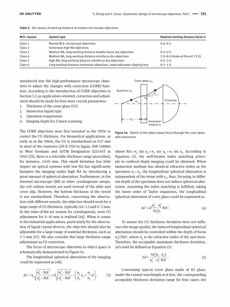
The focus of microscope objectives in object space is schematically demonstrated in Figure 14.
The longitudinal spherical aberration of the imaging could be expressed as [48]:
2 2 2 2
0 02 2 2 2
NA NA,
NA NAI I I I
S GS G
n n n ns s d s d
n nn n − −
∆ = + − + − − ′ (3)
where NA = nS sin uS = nG sin uG = nI sin uI. According to Equation (3), the well-known index matching princi-ple in confocal depth imaging could be obtained. When immersion medium has identical refractive index as the specimen nI = nS, the longitudinal spherical aberration is independent of the terms with s0, thus, focusing in differ-ent depth of the specimen does not induce spherical aber-ration. Assuming the index matching is fulfilled, taking the lower order of Taylor expansion, the longitudinal spherical aberration of cover glass could be expressed as
2 22
3 NA .2G I
G I
n ns d
n n′
−∆ = (4)
To assure the CG thickness deviation does not influ-ence the image quality, the induced longitudinal spherical aberration should be controlled within the depth of focus nSλ/NA2, where nS is the refractive index of the specimen. Therefore, the acceptable maximum thickness deviation, Δd could be defined as Equation (5):
3
2 2 4
4.
NAG I S
G I
n n nd
n nλ
∆ =−
(5)
Concerning typical cover glass made of K5 glass, under the central wavelength at d-line, the corresponding acceptable thickness deviation range for four cases: dry
Table 5: Six classes of working distance of modern microscope objectives.
W.D. classes System type Relative working distance factor k
Class 1 Normal W.D. microscope objectives 0.0–0.5Class 2 Immersion high NA objectives –Class 3 Medium NA, long working distance double-Gauss dry objectives 0.5–2.0Class 4 Medium NA, long working distance retrofocus dry objectives 2.0–8.0 (state-of-the-art 13.0)Class 5 High NA, long working distance retrofocus dry objectives 0.5–2.0Class 6 Long working distance immersion objectives, especially water dipping lens 0.5–1.0
d
Front lens
Cover glass nG
Specimen nS
Immersionmedium nI
uI
uG
uS
s0
Figure 14: Sketch of the object space focus through the cover glass with immersion.

332 Y. Zhang and H. Gross: Systematic design of microscope objectives. Part I
objectives with specimen in air, dry objectives with speci-men in water, water immersion objective with specimen in water and typical oil immersion objectives with specimen in water could be calculated as
∆ ∆
∆ ∆
≤ ≤
≤ ≤
4 4
4 4
0.0063 0.0084mm, mm, NA NA
0.0267 0.7342mm, mm,NA NA
DA DW
W O
d d
d d (6)
respectively. Figure 15 illustrates the tolerable CG thick-ness of these four cases with different NA.
It is self-evident that for dry objective with NA > 0.75, 0.02 mm deviation of the CG thickness would hamper the image quality. Thus, to realise high performance, they must be designed with CORR function, typically utilis-ing movable groups in the objective, to compensate the effect. Concerning the applications requiring a large toler-able CG thickness range, such as the inverted microscope, according to Figure 15, the objective lens cannot have NA above 0.4 (critical NA). Therefore, most of the pat-ented IM objectives have a correction collar incorporated. When it comes to the water immersion objective used for biological specimen, the critical value of NA is around 1.10; therefore, the off-the-shelf water immersion objec-tives with NA > 1.10 are designed with CG CORR function. Because of the small index gap between the immersion medium and cover glass, the oil immersion objectives are sparsely affected by the CG thickness deviation. However, regarding the total internal reflection fluorescence (TIRF) microscopy, because the illuminating light beam should be accurately focused onto the front surface of cover glass
to generate evanescent wave for fluorescence excitation, the extremely high NA objectives should be capable to correct CG thickness.
The immersion correction objective was invented in 1975 [40]. Before 1990s, microscope objectives, which could be utilised for water, glycerin, silicone oil, and oil immersion, were well developed. Under high NA, the change of the refractive index of different immersion liquid varies the working distance and induces spheri-cal aberration. Similar to the idea of CG correction, the induced spherical aberration should be compensated by movable groups. Thereby, this class of high-performance objectives could work for multitasks, especially to match the refractive index of specimen to realise depth imaging with confocal microscopy.
The invention of temperature-correctable systems is mostly oriented to the application of live cell observa-tion, which would be further discussed in Section 5.4. The temperature of live cells is 37°C, which is 14°C higher than the room temperature 23°C. To compensate the induced spherical aberration, these water immersion objectives should be designed with correction collar. Moreover, because the extremely high NA oil immersion objectives are very sensitive to the thermal expansion and refractive index deviation of the oil, they are not only designed with a relatively larger working distance but also capable to compensate the thermal-induced aberration. Therefore, temperature correction collar could be found in most of the oil objectives with NA larger than 1.40.
It is well known that for depth imaging, refractive index of the immersion liquid and the specimen should be matched to avoid tremendous induced spherical
0.0 0.1 0.2 0.3 0.4 0.5 0.6 0.7 0.8 0.9 1.0 1.1 1.2 1.3 1.4 1.51E–3
0.01
0.1
1
10
100T
oler
able
thic
knes
s ∆d
(m
m)
Numerical aperture
Dry in waterWater immersionOil immersion
0.17 ± 0.02 mm
IM 0–2 mm
IM 0.8–1.6 mm
0–10 mm
Dry in air
TIRF
Figure 15: The tolerable CG thickness of dry, water immersion and oil immersion objectives. Dry objective could reach maximum NA of 0.95. Water immersion objectives are typically used for NA from 0.8 to 1.2. The oil immersion objectives usually work for NA from 1.1 to 1.5. Typical values of the CG tolerance of conventional biomedical microscopes and cytodiagnosis setups are plotted.
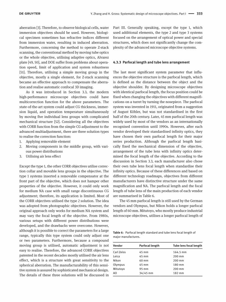
Y. Zhang and H. Gross: Systematic design of microscope objectives. Part I 333
aberration [3]. Therefore, to observe biological cells, water immersion objectives should be used. However, biologi-cal specimen sometimes has refractive indices different from immersion water, resulting in induced aberration. Furthermore, concerning the method to operate Z-stack scanning, the conventional method by moving tube optics or the whole objective, utilising adaptive optics, Alvarez plate [49, 50], and DOE suffer from problems about opera-tion speed, limit of application and system robustness [51]. Therefore, utilising a simple moving group in the objective, mostly a single element, for Z-stack scanning became an effective approach to compensate the aberra-tion and realise automatic confocal 3D imaging.
As it was introduced in Section 3.3, the modern high-performance microscope objectives could have multicorrection function for the above parameters. The state-of-the-art system could adjust CG thickness, immer-sion liquid, and operation temperature simultaneously by moving five individual lens groups with complicated mechanical structure [52]. Considering all the objectives with CORR function from the simple CG adjustment to the advanced multiadjustment, there are three solution types to realise the correction function:1. Applying removable element2. Moving components in the middle group, with vari-
ous power distributions3. Utilising air lens effect
Except the type 1, the other CORR objectives utilise correc-tion collar and movable lens groups in the objective. The type 1 systems inserted a removable compensator at the front part of the objective, which does not hamper other properties of the objective. However, it could only work for medium NA case with small range discontinuous CG adjustment; therefore, its application is limited. Most of the CORR objectives utilised the type 2 solution. The idea was adopted from photographic objectives. However, the original approach only works for medium NA system and may vary the focal length of the objective. From 1980s, various setups with different power distributions were developed, and the drawbacks were overcome. However, although it is possible to correct the parameters for a large range, typically this type system could only adjust one or two parameters. Furthermore, because a compound moving group is utilised, automatic adjustment is not easy to realise. Therefore, the advanced CORR objectives patented in the recent decades mostly utilised the air lens effect, which is a structure with great sensitivity to the spherical aberration. The manufacturability of this sensi-tive system is assured by sophisticated mechanical design. The details of these three solutions will be discussed in
Part III. Generally speaking, except the type 1, which used additional elements, the type 2 and type 3 systems focused on the arrangement of optical power and special structures, which does not significantly change the com-plexity of the advanced microscope objective systems.
4.3.3 Parfocal length and tube lens arrangement
The last most significant system parameter that influ-ences the objective structure is the parfocal length, which is defined as the distance between the object and the objective shoulder. By designing microscope objectives with identical parfocal length, the focus position could be fixed when changing the objectives with different magnifi-cations on a turret by turning the nosepiece. The parfocal system was invented in 1911, originated from a suggestion of August Köhler, but was not standardised in the first half of the 20th century. Later, 45 mm parfocal length was widely used by most of the vendors as an internationally recognised convention until 1990s. However, after each vendor developed their standardised infinity optics, they have chosen their own parfocal length for their major series production. Although the parfocal length basi-cally fixed the mechanical dimension of the objective, arrangement of the tube lens with infinity optics deter-mined the focal length of the objective. According to the discussion in Section 3.3, each manufacturer also chose their own tube lens focal length when standardise their infinity optics. Because of these differences and based on different technology roadmaps, objectives from different manufacturers have distinctive structure under the same magnification and NA. The parfocal length and the focal length of tube lens of the main production of each vendor are summarised in Table 6.
The 45 mm parfocal length is still used by the German vendors and Olympus, but Nikon holds a longer parfocal length of 60 mm. Mitutoyo, who mostly produce industrial microscope objectives, utilises a longer parfocal length of
Table 6: Parfocal length standard and tube lens focal length of major manufactures.
Vendor Parfocal length Tube lens focal length
Carl Zeiss 45 mm 164.5 mmLeica 45 mm 200 mmNikon 60 mm 200 mmOlympus 45 mm 180 mmMitutoyo 95 mm 200 mmAO 34/45 mm 182 mm

334 Y. Zhang and H. Gross: Systematic design of microscope objectives. Part I
95 mm. Based on the relaxed mechanical dimension, it is more realistic to design the retrofocus type long working distance objectives. The objectives from the American Optical Corporation (AO) used their own 34 mm parfo-cal length before 1985 and changed to 45 mm afterwards. 45 mm parfocal length was used for finite microscope with 160 mm mechanical tube length (RMS standard), which equivalent tube lens focal length is approximately 150 mm. When the vendors applied infinity optics, to keep the flexibility of system design, the parfocal length should be scaled with the new focal length of tube lens. However, because of the consideration of convention and ergonom-ics, only Nikon made the change.
The parfocal length basically determines the amount of space for integrating lens elements. With a longer choice, it is possible to design the objective with relaxed arrangement of the components. However, as a drawback, increasing the parfocal length would lead to an adverse effect on ergonomics that the viewing port of upright microscopes and the specimen stage position of inverted microscopes are raised in proportion to the increase of parfocal distance [41].
The arrangement of tube lens of different vendors depends on their strategy for lateral colour correction, which was discussed in Section 4.1.2, and its focal length is selected within the optimal range from 150 to 250 mm. With longer focal length, the chief ray angle of the off-axial field could be reduced, but the mechanical dimension of the whole microscope is enlarged. The selection of tube lens focal length determines the shortest objective focal length of Carl Zeiss and longest objective focal length of Nikon under the same magnification.
Taking the advantage of the relaxed mechanical dimension and longer focal length, Nikon objectives are usually designed with a less sensitive structure. Furthermore, it is also feasible to design 1× objective and even 0.5× macroobjectives using a special two-part struc-ture [53] for the standardised microscope system. Compar-ison of two 100×/1.45 oil immersion objectives is shown in Figure 16. The 45 mm parfocal system is from Carl Zeiss, consisting of 14 elements and semiapochromatic cor-rected from g-line to C-line. The 60 mm parfocal objective is from Nikon, consisting of 17 elements. It is slightly better corrected, with apochromatic performance from g-line to C-line, mainly because of the utilisation of more anoma-lous dispersive materials. Both these two systems are well corrected for large field, but the 45 mm parfocal system is at class 5 without using vignetting, whereas the 60 mm objective, although corrected for a larger field, applied vignetting to control coma. Comparing the front and rear group of these two systems, elements in the 45 mm
parfocal system have stronger curvatures. This is due to the consideration of aberration correction, particularly for more effective NA enlargement with reduced spheri-cal and chromatic aberration and balance of coma. Fur-thermore, the axial track could be shortened to match the parfocal length. However, these strong curved elements always result in greater sensitivity. Therefore, although there are more elements used in the 60 mm parfocal system, because of the better tolerance, the manufactur-ability is better, and the cost might be reduced.
It is worth mentioning to realise extended etendue, particularly up to Zone 4, and extended W.D., all the vendors also extended the parfocal length. 75 mm par-focal length is often used by Nikon and Olympus. Some 105 mm parfocal systems are patented by Carl Zeiss. Con-cerning the extremely high etendue objectives for virtual slides application, the parfocal length is far beyond the conventional limit, reaching 300 mm.
As a conclusion, systems with smaller parfocal length typically have a smaller number of elements but more critical sensitivity. Utilising longer parfocal length, within the larger space, although more elements are used, better tolerance, and reduced cost could be achieved. Some special system properties could be also realised, such as the extreme etendue and very low magnification.
4.3.4 Pupil fixation
In most of the collected patents, information about aper-ture stop is not given. However, in the practical microscope
45 mm
60 mm
100x/1.45 O SF22 mandai USP 7046451
100x/1.45 O SF20 matthae USP 6504653
Figure 16: Layouts of the 45 mm parfocal and 60 mm parfocal 100×/1.45 oil immersion microscope objectives.
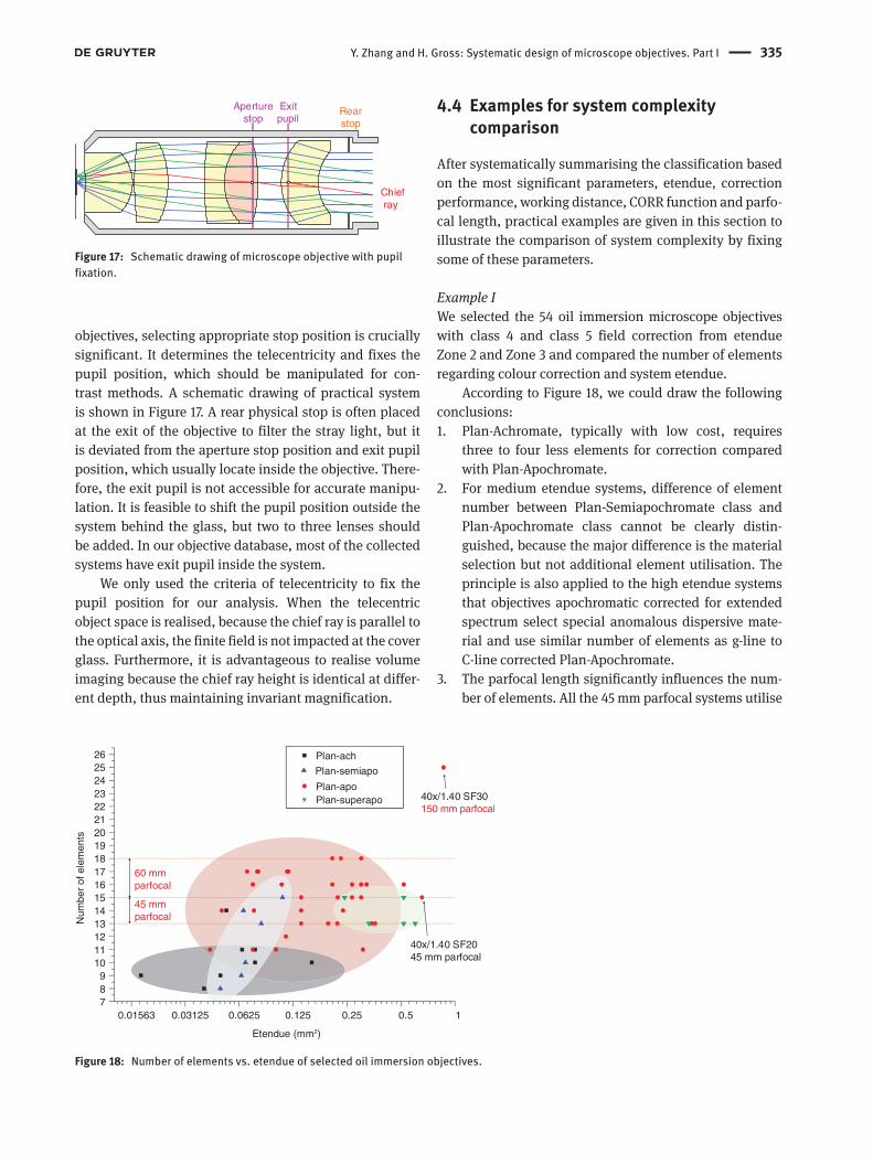
Y. Zhang and H. Gross: Systematic design of microscope objectives. Part I 335
objectives, selecting appropriate stop position is crucially significant. It determines the telecentricity and fixes the pupil position, which should be manipulated for con-trast methods. A schematic drawing of practical system is shown in Figure 17. A rear physical stop is often placed at the exit of the objective to filter the stray light, but it is deviated from the aperture stop position and exit pupil position, which usually locate inside the objective. There-fore, the exit pupil is not accessible for accurate manipu-lation. It is feasible to shift the pupil position outside the system behind the glass, but two to three lenses should be added. In our objective database, most of the collected systems have exit pupil inside the system.
We only used the criteria of telecentricity to fix the pupil position for our analysis. When the telecentric object space is realised, because the chief ray is parallel to the optical axis, the finite field is not impacted at the cover glass. Furthermore, it is advantageous to realise volume imaging because the chief ray height is identical at differ-ent depth, thus maintaining invariant magnification.
4.4 Examples for system complexity comparison
After systematically summarising the classification based on the most significant parameters, etendue, correction performance, working distance, CORR function and parfo-cal length, practical examples are given in this section to illustrate the comparison of system complexity by fixing some of these parameters.
Example IWe selected the 54 oil immersion microscope objectives with class 4 and class 5 field correction from etendue Zone 2 and Zone 3 and compared the number of elements regarding colour correction and system etendue.
According to Figure 18, we could draw the following conclusions:1. Plan-Achromate, typically with low cost, requires
three to four less elements for correction compared with Plan-Apochromate.
2. For medium etendue systems, difference of element number between Plan-Semiapochromate class and Plan-Apochromate class cannot be clearly distin-guished, because the major difference is the material selection but not additional element utilisation. The principle is also applied to the high etendue systems that objectives apochromatic corrected for extended spectrum select special anomalous dispersive mate-rial and use similar number of elements as g-line to C-line corrected Plan-Apochromate.
3. The parfocal length significantly influences the num-ber of elements. All the 45 mm parfocal systems utilise
Exit pupil
Rear stop
Aperture stop
Chief ray
Figure 17: Schematic drawing of microscope objective with pupil fixation.
0.01563 0.03125 0.0625 0.125 0.25 0.5 1789
1011121314151617181920212223242526
Etendue (mm2)
Plan
Plan
Plan
Plan
Plan-ach
Plan-apo
Plan-semiapo
Plan-superapo
60 mm parfocal
45 mm parfocal
40x/1.40 SF30150 mm parfocal
40x/1.40 SF2045 mm parfocal
Num
ber
of e
lem
ents
Figure 18: Number of elements vs. etendue of selected oil immersion objectives.
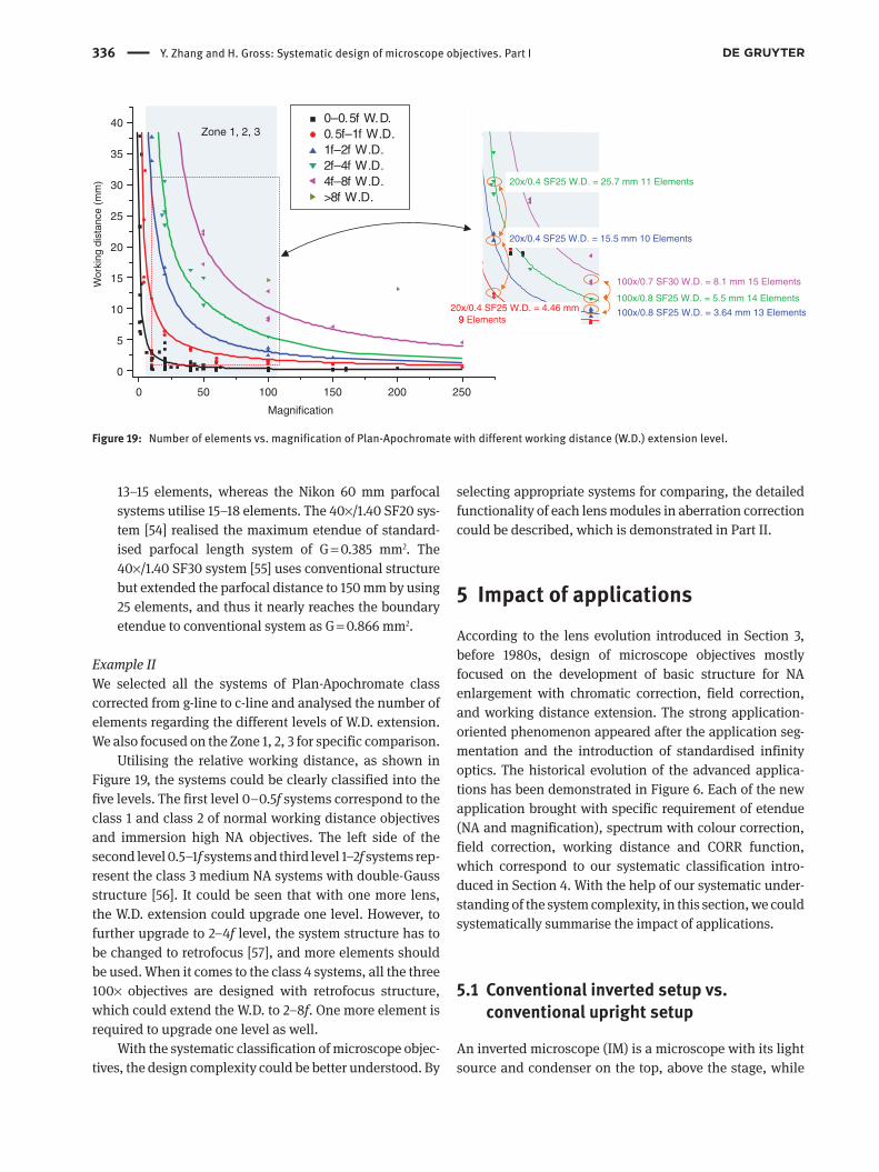
336 Y. Zhang and H. Gross: Systematic design of microscope objectives. Part I
13–15 elements, whereas the Nikon 60 mm parfocal systems utilise 15–18 elements. The 40×/1.40 SF20 sys-tem [54] realised the maximum etendue of standard-ised parfocal length system of G = 0.385 mm2. The 40×/1.40 SF30 system [55] uses conventional structure but extended the parfocal distance to 150 mm by using 25 elements, and thus it nearly reaches the boundary etendue to conventional system as G = 0.866 mm2.
Example IIWe selected all the systems of Plan-Apochromate class corrected from g-line to c-line and analysed the number of elements regarding the different levels of W.D. extension. We also focused on the Zone 1, 2, 3 for specific comparison.
Utilising the relative working distance, as shown in Figure 19, the systems could be clearly classified into the five levels. The first level 0–0.5f systems correspond to the class 1 and class 2 of normal working distance objectives and immersion high NA objectives. The left side of the second level 0.5–1f systems and third level 1–2f systems rep-resent the class 3 medium NA systems with double-Gauss structure [56]. It could be seen that with one more lens, the W.D. extension could upgrade one level. However, to further upgrade to 2–4f level, the system structure has to be changed to retrofocus [57], and more elements should be used. When it comes to the class 4 systems, all the three 100× objectives are designed with retrofocus structure, which could extend the W.D. to 2–8f. One more element is required to upgrade one level as well.
With the systematic classification of microscope objec-tives, the design complexity could be better understood. By
selecting appropriate systems for comparing, the detailed functionality of each lens modules in aberration correction could be described, which is demonstrated in Part II.
5 Impact of applicationsAccording to the lens evolution introduced in Section 3, before 1980s, design of microscope objectives mostly focused on the development of basic structure for NA enlargement with chromatic correction, field correction, and working distance extension. The strong application-oriented phenomenon appeared after the application seg-mentation and the introduction of standardised infinity optics. The historical evolution of the advanced applica-tions has been demonstrated in Figure 6. Each of the new application brought with specific requirement of etendue (NA and magnification), spectrum with colour correction, field correction, working distance and CORR function, which correspond to our systematic classification intro-duced in Section 4. With the help of our systematic under-standing of the system complexity, in this section, we could systematically summarise the impact of applications.
5.1 Conventional inverted setup vs. conventional upright setup
An inverted microscope (IM) is a microscope with its light source and condenser on the top, above the stage, while
0 50 100 150 200 250
Magnification
0
5
10
15
20
25
30
35
40 0–0.5f W.D.0.5f–1f W.D.1f–2f W.D.2f–4f W.D.4f–8f W.D.>8f W.D.
9 Elements
20x/0.4 SF25 W.D.=15.5mm 10 Elements
20x/0.4 SF25 W.D. =25.7mm 11 Elements
100x/0.8 SF25 W.D. = 3.64 mm 13 Elements
100x/0.8 SF25 W.D. = 5.5 mm 14 Elements
100x/0.7 SF30 W.D. = 8.1 mm 15 Elements
20x/0.4 SF25 W.D. = 4.46 mm 9 Elements
20x/0.4 SF25 W.D. = 15.5 mm 10 Elements
20x/0.4 SF25 W.D. = 25.7 mm 11 Elements
Zone 1, 2, 3
Wor
king
dis
tanc
e (m
m)
Figure 19: Number of elements vs. magnification of Plan-Apochromate with different working distance (W.D.) extension level.

Y. Zhang and H. Gross: Systematic design of microscope objectives. Part I 337
the objectives are below the stage pointing up. The IM has been invented for a long time, first introduced in 1850 by Smith [58]. It has been applied to metallurgical applica-tion in the middle of the 20th century, but concerning biomedical applications, the popular application with IM started from 1980s because of the increasing demand of cell culture observation. A comparison of the conven-tional inverted setup and the upright setup is shown in Figure 20. The conventional upright microscope objec-tive images the specimen between the cover slip and slide glass. Thickness of the cover slip was standardised, which is typically 0.17 mm for biomedical applications. But the thickness of slide glass was not standardised and usually varies between 1.2 and 1.7 mm for different applications. The cover glass thickness typically has a tolerance of ±0.02 mm. Therefore, as it was introduced in Section 4.3.2, for high NA systems, the high-performance objectives must be able to compensate the induced spherical aberration. When it comes to the conventional inverted microscope objective, it images the cell floating in the culture medium through the bottom of the cell culture dish. The cell does not perfectly locate at the bottom surface, leaving a vari-able distance, and the bottom thickness of the dish was also not standardised, varying between 0.5 and 1.5 mm. Furthermore, the inverted objectives often work with slide glass or without substrate. Consequently, the conven-tional inverted microscope objective with NA > 0.4 must be designed with correction ring for 0–2 mm CG correction.
As the correction range is large, the objective must be flexible for a large scale of working distance. Thus, the conventional inverted objectives were designed with rela-tively longer working distance, typically 0.5–1 f. The longer working distance always bring with more challenging cor-rection of chromatic aberration, spherical aberration and coma. Because of this effect and the large-range CORR, the correctable maximum etendue is limited around G = 0.1 mm2. Figure 21 gives the off-the-shelf objectives with long working distance (LD) and long CORR range (>0.6 mm) from the catalogs of the major vendors Nikon, Olympus and Carl Zeiss. 20×/0.40, 40×/0.60, 60×/0.70
are the typical magnification and NA combinations. The state-of-the-art 40×/0.78 objective utilised a special sensi-tive element in the middle group and realised 0–1.6 mm CG adjusted under the high NA [59].
It is worth mentioning, in the current microscopy applications, the LD and large CORR range objectives are not only used for IM. Biological routine applications, particularly for cytodiagnosis, have similar requirements and this kind of LD objectives are also used in upright setups.
Recently, for confocal fluorescence microscopy, culture dishes with thickness of 0.14–0.20 mm and low autofluorescence have been widely used. Therefore, typical high NA systems with narrow range CORR could also be used for current advanced inverted microscopes.
5.2 Confocal setup
The confocal microscopy originated from the idea of M. Minsky in 1957 [60] and confocal imaging was developed
Cell culture dish
Culture medium
Cell
SlideCover slip
Invertedmicroscopic
objective
Uprightmicroscopic
objective
0.5–1.5 mmVariable
0.17 ± 0.02 mm1.2–1.7 mm
A B
Figure 20: Comparison of (A) conventional inverted microscope observation and (B) upright microscope observation.
20 40 60 80 100
0.4
0.5
0.6
0.7
0.8
0.9
NikonOlympusCarl zeissCollected
NA
Magnification
Figure 21: Off-the-shelf objectives with long working distance and large range CORR from the major manufactures and our collected database.
338 Y. Zhang and H. Gross: Systematic design of microscope objectives. Part I
during the 1960s. But after the introduction of laser illu-mination in the 1970s [61] and the invention of confocal laser-scanning microscope (CLSM) in the middle of 1980s [62], the confocal setup was eventually incorporated into the standardised microscope systems of major vendors and widely used for biomedical applications. The princi-ple of confocal microscopy has been well discussed in lit-eratures [63, 64]. Utilising the pinhole filtering, the major advantages of confocal microscopy are the improved axial and radial resolution and the feasibility of 3D volume imaging with optical sectioning.
To realise the optical section, according to the discus-sion in Section 4.3.2, there are three requests for CORR function. First, to avoid the spherical aberration induced by different Z-stacks, the refractive index of the immer-sion liquid and the specimen should be matched. For biomedical applications, typically, water immersion is utilised with its d-line refractive index varying between 1.33 and 1.38 with certain solution. However, the con-ventional material cover slips, such as K5 glass, typically have a refractive index gap at least 0.1 compared with the water. Therefore, according to Figure 15, water immersion objectives with NA larger than 1.10 must be designed with CG correction ring. One special solution to overcome this problem is to utilise special cover slip made of fluorocar-bon resin, e.g. cytop [65]. Because the difference between the refractive index of this material and water is only 0.02 or less, a larger deviation of CG thickness is acceptable, which is similar to the conventional oil immersion case. Moreover, the material has far lower water absorption degree than other materials with similar index, such as PMMA, and good UV transmittance with low autofluores-cence. Therefore, it is a good choice for precise confocal fluorescence microscopy. Second, the high NA objectives used in confocal setup sometimes do not only work with water immersion; immersion liquids such as silicone oil, glycerin and oil are also applied to match the index of other specimens or realise better resolution. Therefore, an advanced class of objectives was invented with immersion correction. Third, to realise fast and robust scanning, the recently developed objectives are designed with a light weight simple moving group for depth correction.
When it comes to the impact of confocal setup on the basic properties of microscope objective, to realise more efficient 3D reconstruction of the object with high reso-lution, particularly with the help of postmagnification, objectives with high NA and large observation field are preferred. Furthermore, because laser scanning is used to obtain the image, the requirement of field flatness is higher than conventional systems. The field aberrations should also be controlled, and the relative illumination
of the image edge should be improved with less vignet-ting. Therefore, the advanced microscope objectives used in confocal setup are designed with medium etendue and excellent field correction of class 5.
5.3 General consideration of fluorescence microscopy
The idea of fluorescence microscopy originated from August Köhler in 1904, but it was not widely used until 1970s. From the beginning of 1980s, some microscope objectives are specifically designed for fluorescence microscopy, particularly for i-line UV excitation. The importance of fluorescence microscopy significantly increases from 1990s, especially for biomedical applica-tions. The demand of live cell observation has grown, in which the observation target turned from the structure of the cells towards the behavior of molecules. The avail-ability of green fluorescent protein (GFP) and its deriva-tives assured the possibility of observation and redefined fluorescence microscopy. Nowadays, the development of advanced fluorescence microscopy techniques is still flourishing.
Most of the current fluorescence microscopes are implemented with reflected light fluorescence setup (epi-fluorescence), which utilises the epi-illumination setup consisting of a light source, an excitation mirror to filter the operating wavelength, a dichroic mirror letting the longer wavelength fluorescence pass and an emission filter for further filtering. The epifluorescence setup has great advantage in analysing opaque material with higher fluorescence intensity, and it is possible to be combined with other transmitted light methods.
Generally, the epifluorescence microscopy has the fol-lowing six major requirements for the objective:1. High NA in the object space2. Relatively large NA in the image space3. High transmittance over wide spectrum4. Favorable chromatic correction over wide spectrum5. Favorable field correction6. Low autofluorescence
To intensify the fluorescence, the intensity of the excita-tion illumination light should be enlarged. Therefore, under the epi-illumination setup, the corresponding object space NA is required to be high. The resolution is improved simultaneously for more detailed observation. Furthermore, because the fluorescence emitted from the specimen is typically weak, to increase the brightness of image for more efficient observation, a larger image space

Y. Zhang and H. Gross: Systematic design of microscope objectives. Part I 339
NA is also required. Concerning the first two requirements simultaneously, the optimal magnification should be reduced.
When it comes to the system performance, first the specific excitation and emission wavelengths for fluo-rescence significantly change the requirement of system correction regarding spectrum. For one thing, the working wavelengths of popular fluorescent dyes and fluorescent proteins cover a wide range. For instance, Fura-2 for Ca2 + detection is exited at 340 and 380 nm in UV, Kaede and PAGFP are exited around 400 nm, and CFP, GFP, YFP have their peak excitation wavelengths at 430, 488 and 514 nm, respectively. Because of the high fluorescent efficiency, the UV excitation is of great interest for all the applica-tions. Therefore, to assure the high intensity of illumi-nation light, which passed through the objective, high transmittance over the wide spectrum from UV to VIS is required. Because of the limit of material, the UV trans-mission of conventional microscope objectives is usually low. In the 1980s, the specific objectives designed for fluorescence microscopy could realise over 60% transmit-tance at i-line (365 nm). The advanced fluorescent micro-scope objectives could realise high transmittance of 80% from i-line in UV to s-line in NIR and more than 60% trans-mittance at 340 nm. Some special systems even realised good transmission for 300 nm excitation. Beside the illu-mination light path, when we consider the imaging path, for another, because the peak emission wavelength of the fluorescent dyes and proteins also covers a wide range from UV to VIS, to realise fluorescence observation for various applications, particularly for multicolour imaging with multicoloured fluorescent tag, the chromatic aberra-tion should be superapochromatic corrected for this wide spectrum, corresponding to the class (d) and (g) intro-duced in Section 4.1.1.
To improve the operability of the microscope and observe large field at the same time, improved field cor-rection is also required, typically as class 4 introduced in Section 4.1.2. The low autofluorescence is the last require-ment in the current advanced fluorescence microscopy to further improve contrast. In the epi-illumination setup, because the illumination light coming from the rear part of the objective is intensified, if the intrinsic auto-fluorescence of the optical elements is high, stray light is induced and thus degrades image quality and hampers the image contrast. Therefore, in the advanced objectives, with respect to both the requirement 3 and requirement 6, optical materials with high UV transmission and low autofluorescence are selected. However, because of the limit of material choice, excellent chromatic correction becomes difficult. To overcome the contradiction, special
glass pairs have been discovered and utilised in special lens modules, which will be discussed in Part II.
5.4 Live cell and specimen observation
In the old microscopic observation for biological applica-tions before 1950s, the cells must be stained. The invention of phase contrast microscopy makes it feasible to observe the structure of live cells. However, when the behavior of molecules in the live cells became the major interest, despite the general considerations of fluorescence micro-scopy, special requirements are involved in the design of live cell and specimen observation apparatus. Moreover, to obtain the 3D image of the live tissues, it is difficult to use conventional confocal setup for Z-stack scanning. Taking the advantage of the operating spectrum as well, therefore, utilisation of multiphoton excitation is becoming popular. This nonlinear microscopy approach also imposed several new requirements on the objective design.
5.4.1 General consideration
When the fluorescence observation is performed on live cells, the fluorescent substance is used to stain the living specimen. Corresponding to the general require-ment of fluorescence microscopy, the objectives should be designed with large object space NA, which is also required in live cell observation to detect as much infor-mation from the cell at a time. Furthermore, it is also desired to keep a state of live cell behavior in the sight for a longer time observation; thus a wider object field size is required. Consequently, the etendue of the live cell obser-vation objectives should be large.
A specific requirement of live cell and specimen fluo-rescence observation is to reduce the cell toxicity. When some stimulus, such as the excitation light, is given to the live specimen, there is the possibility that the stimulus itself adversely affects an active state of the cell. Although UV light has high fluorescent efficiency, it results in critical phototoxicity. Therefore, light in IR range is usually used in live cell observation with new approaches for various applications, including multiphoton, CARS, SHG, IRDIC and optical tweezers. Conventional fluorescence obser-vation methods could also be operated within IR range, using fluorescence substance with long wavelength exci-tation. There are three major advantages of utilising IR light in live cell observations:1. Beneficial from the longer wavelength, the scatter-
ing and absorption of IR light in the live specimen is
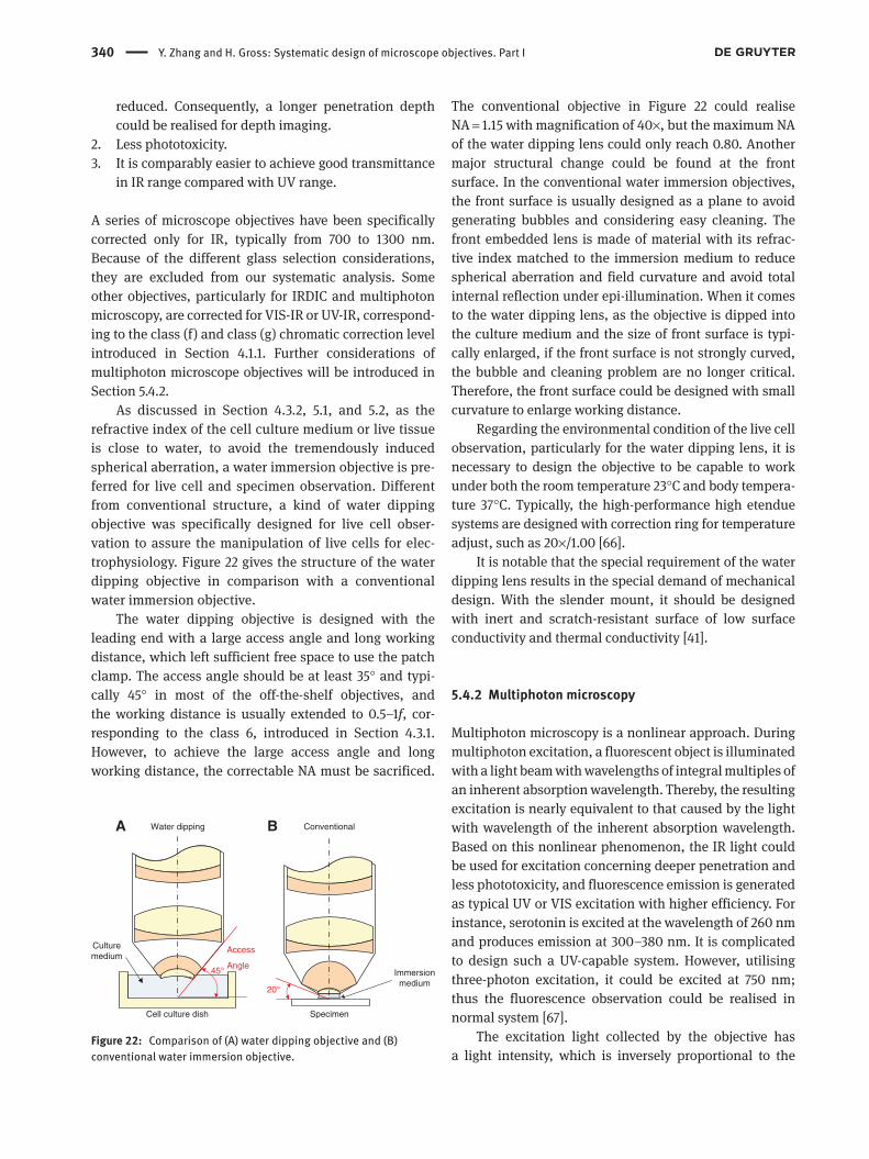
340 Y. Zhang and H. Gross: Systematic design of microscope objectives. Part I
reduced. Consequently, a longer penetration depth could be realised for depth imaging.
2. Less phototoxicity.3. It is comparably easier to achieve good transmittance
in IR range compared with UV range.
A series of microscope objectives have been specifically corrected only for IR, typically from 700 to 1300 nm. Because of the different glass selection considerations, they are excluded from our systematic analysis. Some other objectives, particularly for IRDIC and multiphoton microscopy, are corrected for VIS-IR or UV-IR, correspond-ing to the class (f) and class (g) chromatic correction level introduced in Section 4.1.1. Further considerations of multiphoton microscope objectives will be introduced in Section 5.4.2.
As discussed in Section 4.3.2, 5.1, and 5.2, as the refractive index of the cell culture medium or live tissue is close to water, to avoid the tremendously induced spherical aberration, a water immersion objective is pre-ferred for live cell and specimen observation. Different from conventional structure, a kind of water dipping objective was specifically designed for live cell obser-vation to assure the manipulation of live cells for elec-trophysiology. Figure 22 gives the structure of the water dipping objective in comparison with a conventional water immersion objective.
The water dipping objective is designed with the leading end with a large access angle and long working distance, which left sufficient free space to use the patch clamp. The access angle should be at least 35° and typi-cally 45° in most of the off-the-shelf objectives, and the working distance is usually extended to 0.5–1f, cor-responding to the class 6, introduced in Section 4.3.1. However, to achieve the large access angle and long working distance, the correctable NA must be sacrificed.
The conventional objective in Figure 22 could realise NA = 1.15 with magnification of 40×, but the maximum NA of the water dipping lens could only reach 0.80. Another major structural change could be found at the front surface. In the conventional water immersion objectives, the front surface is usually designed as a plane to avoid generating bubbles and considering easy cleaning. The front embedded lens is made of material with its refrac-tive index matched to the immersion medium to reduce spherical aberration and field curvature and avoid total internal reflection under epi-illumination. When it comes to the water dipping lens, as the objective is dipped into the culture medium and the size of front surface is typi-cally enlarged, if the front surface is not strongly curved, the bubble and cleaning problem are no longer critical. Therefore, the front surface could be designed with small curvature to enlarge working distance.
Regarding the environmental condition of the live cell observation, particularly for the water dipping lens, it is necessary to design the objective to be capable to work under both the room temperature 23°C and body tempera-ture 37°C. Typically, the high-performance high etendue systems are designed with correction ring for temperature adjust, such as 20×/1.00 [66].
It is notable that the special requirement of the water dipping lens results in the special demand of mechanical design. With the slender mount, it should be designed with inert and scratch-resistant surface of low surface conductivity and thermal conductivity [41].
5.4.2 Multiphoton microscopy
Multiphoton microscopy is a nonlinear approach. During multiphoton excitation, a fluorescent object is illuminated with a light beam with wavelengths of integral multiples of an inherent absorption wavelength. Thereby, the resulting excitation is nearly equivalent to that caused by the light with wavelength of the inherent absorption wavelength. Based on this nonlinear phenomenon, the IR light could be used for excitation concerning deeper penetration and less phototoxicity, and fluorescence emission is generated as typical UV or VIS excitation with higher efficiency. For instance, serotonin is excited at the wavelength of 260 nm and produces emission at 300–380 nm. It is complicated to design such a UV-capable system. However, utilising three-photon excitation, it could be excited at 750 nm; thus the fluorescence observation could be realised in normal system [67].
The excitation light collected by the objective has a light intensity, which is inversely proportional to the
Immersionmedium
SpecimenCell culture dish
Culturemedium
Access
Angle45°
20°
Water dipping ConventionalA B
Figure 22: Comparison of (A) water dipping objective and (B) conventional water immersion objective.
Y. Zhang and H. Gross: Systematic design of microscope objectives. Part I 341
square of the distance from the focal plane in geometri-cal approximation. Therefore, the multiphoton excita-tion only occurs in the vicinity of the focal point, and thus, fluorescence is only emitted from the focal plane. Advantageously, fluorescence in samples is subject to less discolouration, and the confocal setup with confocal pinholes is no longer necessary to realise depth imaging. Consequently, multiphoton microscopy became the most popular tool for 3D imaging of live cell and specimen.
However, also owing to these effects, design of mul-tiphoton microscope objectives became more challeng-ing. First, to reduce the area of excitation and emission, larger NA is preferred to achieve better resolution. Second, because the excitation (IR) and emission (UV/VIS) with different wavelengths occurred at the same position, the chromatic aberration of wide spectrum from UV to IR must be well corrected, as the class (g). The objective should also have excellent transmittance through the full spec-tral range. Third, although the IR excitation light has low scattering, the emission light, which lies within UV and VIS, may become diffused in the specimen. Therefore, to collect the scattered fluorescence without loss, the objec-tive should be designed with large field. Combining with the first requirement, the etendue is enlarged. Lastly, for a large depth imaging, the working distance should also be comparably enlarged, but typically still within 0–0.5f. Concerning the different depth, to reduce the spheri-cal aberration induced by the index change of specimen and realise fast autoscanning, the objective should be designed with a moving group for depth correction.
5.5 Total internal reflection fluorescence microscopy (TIRFM)
The TIRFM utilises total internal reflection (TIR) in prism or cover glass and thus could be classified as trans-TIRFM (prism- and lightguide-based TIRFM) and cis-TIRFM (through-objective TIRFM), respectively. In this section, we only focus on the cis-TIRFM utilising high NA objective. The excitation of TIRFM is produced by the TIR with the evanescent wave at the surface between the cover glass and specimen. Therefore, the penetration depth is very small, approximately as the wavelength of the illumina-tion light. By only exciting such a thin section, extremely high SNR could be achieved. To realise the TIR at the cover glass, the NA of TIRF objective should be larger than 1.38, which is the typical refractive index of cells. The practi-cal TIRF objectives are typically designed with NA > 1.42, and according to the discussion in Section 4.2, Nikon and Olympus utilised special oil to make the NA exceeding
1.65, even reaching 1.70. Nevertheless, the special oils have strong autofluorescence, hampering the image con-trast. TIRF objectives utilising typical Type A oil with NA between 1.45 and 1.49 are favorable.
However, belonging to the high NA objectives, the requirement of TIRF objectives is different from the typical high NA objectives for confocal fluorescence microscopy. According to Sections 5.2 through 5.4, the typical high NA systems require large object field for more efficient obser-vation. On the contrary, to further improve the SNR, the TIRFM only illuminates a small area; thus the TIRF objec-tives are typically designed with large magnification, typi-cally from 60× to 160×.
Another special requirement of TIRF objective is the CORR function of CG thickness and temperature. Owing to the application principle of TIRF, the excitation laser beam should be perfectly focused onto the front surface of cover slip. Therefore, when the CG thickness is under bias use, the induced spherical aberration should be cor-rected. Furthermore, immersion oil always suffers from critical index thermal change and thermal expansion. When the TIRF is used under body temperature, the cor-responding error should also be corrected. As a typical range, TIRF objectives have CORR function of CG thick-ness 0.13–0.19 mm at 23°C and 0.14–0.20 mm at 37°C.
5.6 Virtual slide microscopy
The digital image sensor developed rapidly in the recent decade. The number of pixels of the sensor used for digital microscopy has increased remarkably. There is a growing demand for the microscope apparatus to achieve both a wide field of view and high resolving power in obser-vation. Fulfilling these requirements, the virtual slide microscope became the state-of-the-art research tool for brightfield and fluorescence microscopy.
The basic idea of a virtual slide microscope is the combination of wide field fluorescence observation and confocal Z-stack scanning. However, compared with conventional microscope objective for confocal setup, the magnification is further reduced to 10×–20× achiev-ing object diameter of 1.5–2.5 mm, and the NA is further enlarged reaching 0.9–0.95 for dry lens and 1.35–1.45 for oil immersion objectives. Thereby, the extreme etendue of microscope objectives is required.
When it comes to the system performance, to realise efficient field scanning, the same as conventional confo-cal setup, all the field aberrations should be corrected. The objective should also be at least apochromatic corrected for VIS and with excellent transmittance from UV to VIS,

342 Y. Zhang and H. Gross: Systematic design of microscope objectives. Part I
which correspond to the requirement of general fluores-cence microscopy. However, because of the extremely high etendue, it became more challenging to correct both the axial aberrations (spherical aberration and longitudinal chromatic aberration) and the field aberrations. For best case, the longitudinal aberrations should be corrected as class (c) or class (d), and field aberrations should be cor-rected without vignetting to ensure uniform illumination of the full field as class 7. Nevertheless, as introduced in Section 4.3.3, parfocal length must be sacrificed to achieve this level correction. Furthermore, with the small mag-nification, as the exit pupil size increases significantly, the coma cannot be controlled. Therefore, some state-of-the-art systems [55] utilised retrofocus structure, which increased the ray height in the middle group but reduced the relative ray height in the rear group to control coma, while some other state-of-the-art systems [38] abandoned the infinity optics to achieve perfect axial and field cor-rection. Generally speaking, to realise the extremely high etendue correction, trade-off between vignetting, parfocal length and entire microscope size must be made to deter-mine the basic objective structure.
The virtual slide microscope was invented to achieve high scanning speed. However, to operate Z-stack scan-ning, the conventional method that moves the entire heavy objective would induce vibrations and the speed is low. Introducing special optical elements with zooming effect, such as adaptive elements and Alvarez plate, would bring with necessity of pupil arrangement, thus increasing system complexity. Utilising DOE is also feasible, but typi-cally results in critical stray light. Consequently, a light-weight moving group should be used in the virtual slide microscope objectives for efficient depth adjustment.
5.7 Semiconductor industrial applications
From 1980s, following the flourish of semiconductor industry, a series of microscope objectives was specifi-cally designed for industrial inspection, repairing and fabrication. The observation sample was not fixed as semiconductor chips, and the application was not fixed as inspection, but in this paper, we mostly named this series of objectives as semiconductor inspection objective.
The semiconductor inspection lens is used to resolve the fine structure of the sample. Therefore, except some very low magnification objectives for positioning, the conventional semiconductor inspection lens requires large magnification (50×–250×) and high NA without immersion. Moreover, a long working distance is also required for repairing and fabrication. However, it is
well known that with increasing magnification (reduc-ing focal length), the chromatic aberration gets critical and with increasing working distance the spherical aber-ration, field curvature, coma and chromatic aberration gets severe [68]. Combining these two effects, therefore, as the retrofocus structure is applied, the enlargement of NA has contradiction with the extension of W.D. Compar-ing the class 4 and class 5 introduced in Section 4.3.1, trade-off between NA and W.D. should be made for the high magnification industrial objective. Typical class 4 systems are designed as 100×/0.50 with k = 6.5, and the class 5 systems are designed as 100×/0.90 with k = 1.12. Recently, utilising advanced digital image sensor, high-resolution wide-field image could be obtained with postmagnification. Therefore, similar to virtual slide microscope, the low magnification high NA objective with long working distance has become a new interest. However, owing to the complexity, the number of inven-tions is still limited.
According to the introduction in Section 4.1.1, regard-ing operation spectrum, except the DUV objectives, the semiconductor inspection objectives should work for VIS and possible extension to UV or IR, which are mostly based on the wavelength of YAG laser and its harmonics for laser repairing. The semiconductor industrial objec-tives extended the corrected spectrum and improved the transmittance before the biomedical fluorescence micro-scope objectives. Concerning the correction level, most of the biomedical fluorescence objectives at least real-ised Apochromate correction in VIS, but some industrial objectives only, achieved Achromate or Fluorite correction through the full spectrum.
The semiconductor inspection objectives typically require better field correction than the biomedical objec-tives with similar etendue and colour correction. For one thing, the illumination uniformity should be superb; thus, vignetting cannot be accepted. In addition, higher-order field aberrations including the chromatic variation of coma, which are not considered in other applications, could also influence the precise inspection. The class 5 field correction is usually required for the industrial objectives.
The conventional semiconductor industrial objectives were mostly designed without CORR function. However, in the recent 20 years, there is an increasing demand of inspection under glass plate, particularly for the inspec-tion of liquid crystal substrate. The variable thickness of the substrate is typically around 2–5 mm. Therefore, the corresponding inspection lens should be designed with large-range CG correction, the same as the objective used for biological IM setup.
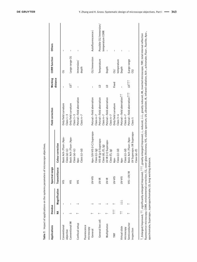
Y. Zhang and H. Gross: Systematic design of microscope objectives. Part I 343
Tabl
e 7:
Im
pact
of a
pplic
atio
ns o
n th
e sy
stem
s pa
ram
eter
s of
mic
rosc
ope
obje
ctiv
es.
Appl
icat
ions
Et
endu
e
Spec
tral r
ange
Fi
eld
corr
ectio
n
Wor
king
di
stan
ce
CORR
func
tion
Ot
hers
NA
Mag
nific
atio
nTr
ansm
ittan
ce
Colo
ur co
rrec
tion
Conv
entio
nal
obje
ctiv
e
–
–
VIS
Ba
sic A
ch-/
Fluo
r-/Ap
o-Cl
ass
(a)–
(c)
On
ly fi
eld
curv
atur
eCl
ass
1–3
–
CG
–
Conv
entio
nal I
M
↓
–
VIS
Ba
sic A
ch-/
Fluo
r-/Ap
o-Cl
ass
(a)–
(c)
On
ly fi
eld
curv
atur
eCl
ass
1–3
LD
↑
Larg
e ra
nge
CG
–
Conf
ocal
set
up
↑
↓
VIS
Ap
o-Cl
ass
(c)–
(d)
Pe
tzva
l + fi
eld
aber
ratio
nCl
ass
4–7
–
Im
mer
sion
/de
pth
–
Fluo
resc
ence
m
icro
scop
y
Ge
nera
l
↑
↓
UV-V
IS
Apo-
/UV-
VIS
(i-C)
Sup
erap
o-Cl
ass
(c)–
(g)
Pe
tzva
l + fi
eld
aber
ratio
nCl
ass
4–7
–
CG
/im
mer
sion
Au
toflu
ores
cenc
e↓
Ge
nera
l liv
e ce
ll
↑
↓
UV-IR
VI
S-IR
(g-t)
Sup
erap
o-Cl
ass
(d),
(f), (
g)
Petz
val +
fiel
d ab
erra
tion
Clas
s 4–
7
LD
Tem
pera
ture
Po
ssib
le C
G/im
mer
sion
/te
mpe
ratu
re C
ORR
M
ultip
hoto
n
↑
↓
UV-IR
UV
-IR (i
-t) S
uper
apo-
Clas
s (f)
, (g)
Pe
tzva
l + fi
eld
aber
ratio
nCl
ass
4–7
LD
De
pth
–
TI
RF
↑↑↑
↑
UV
-VIS
Ap
o-Cl
ass
(c)–
(d)
On
ly fi
eld
curv
atur
eCl
ass
3–4
Fi
xed
CG
/te
mpe
ratu
re
–
Virtu
al s
lide
mic
rosc
opy
↑↑
↓↓
↓
UV-V
IS
Apo-
Clas
s (c
)–(d
)
Petz
val +
fiel
d ab
erra
tion↑
↑Cl
ass
6–7
–
De
pth
–
Sem
icon
duct
or
insp
ectio
n
↑
↑
VIS
+ UV
/IR
Ba
sic A
ch-/
Fluo
r-/Ap
o-UV
Sup
erap
o-/I
R Su
pera
po-
Clas
s (a
)–(f)
Pe
tzva
l + fi
eld
aber
ratio
n↑↑↑
Clas
s 5
LD
↑↑↑
(L
arge
rang
e CG
)
-
↑, E
nlar
ged/
impr
oved
; ↑↑,
sig
nific
antly
enl
arge
d/im
prov
ed; ↑
↑↑, g
reat
ly e
nlar
ged/
impr
oved
; ↓, r
educ
ed; ↓
↓↓, g
reat
ly re
duce
d; IM
, inv
erte
d m
icro
scop
e; T
IRF,
tota
l int
erna
l ref
lect
ion
fluor
esce
nce
mic
rosc
opy;
COR
R, e
nviro
nmen
tal c
orre
ctio
n; C
G, co
ver g
lass
thic
knes
s; V
IS, v
isib
le s
pect
rum
; UV,
ultr
avio
let;
IR, i
nfra
red
radi
atio
n; A
ch-,
achr
omat
e; Fl
uor-,
fluo
rite;
Apo
-, ap
ochr
omat
e; S
uper
apo-
, sup
erap
ochr
omat
e; L
D, lo
ng w
orki
ng d
ista
nce.

344 Y. Zhang and H. Gross: Systematic design of microscope objectives. Part I
5.8 Miscellaneous
Most of the remarkable biomedical and industrial appli-cations have been discussed above. Some additional important applications also have slight impact on the basic parameter and system complexity of the microscope objectives.
Metallurgical microscope utilised epi-illumination to observe the opaque substances with brightfield or dark-field observation. The metallurgical microscope has been developed over centuries, and the typical magnification, NA and system structures are similar to the conventional biomedical objectives. Concerning the observation of metal, under the epi-illumination, the veiling glare gen-erated by the air-to-lens interfaces, which are not well coated, would significantly influence the metallurgical analysis. Therefore, typically more cemented elements are used in the metallurgical microscope objectives instead of single lens to control the stray light.
Polarization microscope utilised polarised light for observation. Therefore, to achieve the best image, it is impor-tant to reduce the intrinsic influence of the objective on the polarization. For one thing, utilisation of crystal should be avoided, including calcium fluoride, which is commonly used to correct secondary spectrum for Apochromate. For another, the impact of strain and birefringence from the optical elements, optical cements and coatings should be reduced. The objective should be designed with fewer elements. Because of the limit of material and number of elements, typically the polarization microscope objectives could only reach a medium NA and small etendue with low-level chromatic correction at class (a) or class (b) and low-level field correction at class 1 and class 2.
Contrast methods, such as phase contrast and DIC, are widely used in modern microscopy. The system struc-ture should ensure the manipulation on the pupil of the objective. However, for the high-performance systems, the space in the objective is usually fully filled with lenses, and the exact pupil position is inside the objective. One solution is to put an artificial aperture at the rear part of the objective, as shown in Figure 17, but the manipula-tion is not accurate. Another solution is introducing two th three more special lenses to design the objective with accessible pupil behind the glass, but the system com-plexity is slightly increased. It is also feasible to utilise pupil relay system, but the mechanical track of the whole system is enlarged. Except this effect, the contrast method does not have other impact on the complexity of micro-scope objective.
Recently, following the development of the super-resolution localization microscopy methods, many
manufactures specifically produced specific high-per-formance objectives. The basic design consideration is the same as basic high NA high magnification confocal and fluorescence microscope objective. Both the chro-matic and field correction should reach high level class (d) and class 5 with excellent CORR function of CG and temperature correction. A new feature of the localization microscopy is the strong illumination intensity. Under the high NA, the strong power gathered at the front group may damage the surface and cementing (the glue is usually sensitive to the UV light). Therefore, the front group is sometimes specifically rearranged.
5.9 Summary
Impacts of the discussed applications on the design of microscope objectives are summarised in Table 7.
6 Impact of manufacture and technology consideration
Compared with the impact of applications, the impact of manufacture and technology consideration is far more dif-ficult to be systematic summarised. Most of the considera-tions originated from the technique roadmaps and process details of the manufacturer, which are typically kept as a secret. Because our work is to analyse the general lens modules influencing system complexity, we would focus on the most important four considerations as follow:1. Manufacture accuracy of the optical elements2. Element mounting and air gaps alignment3. Dimensional restriction4. Stray light control
The detailed discussion of each lens modules with these considerations will be given in Part II. In this section, two examples are used to illustrate the consideration of 1&2 and 3&4, respectively.
Example IFigure 23 shows three different front group structures of high magnification oil immersion objectives from prac-tical patented systems. All the objectives are apochro-matic corrected for visible range from g-line to C-line. The front group (A) utilised a simple hemisphere made of crown glass with matched index to the immersion oil. The front group (B) is the most popular layout, utilis-ing an embedded small crown lens with matched index,
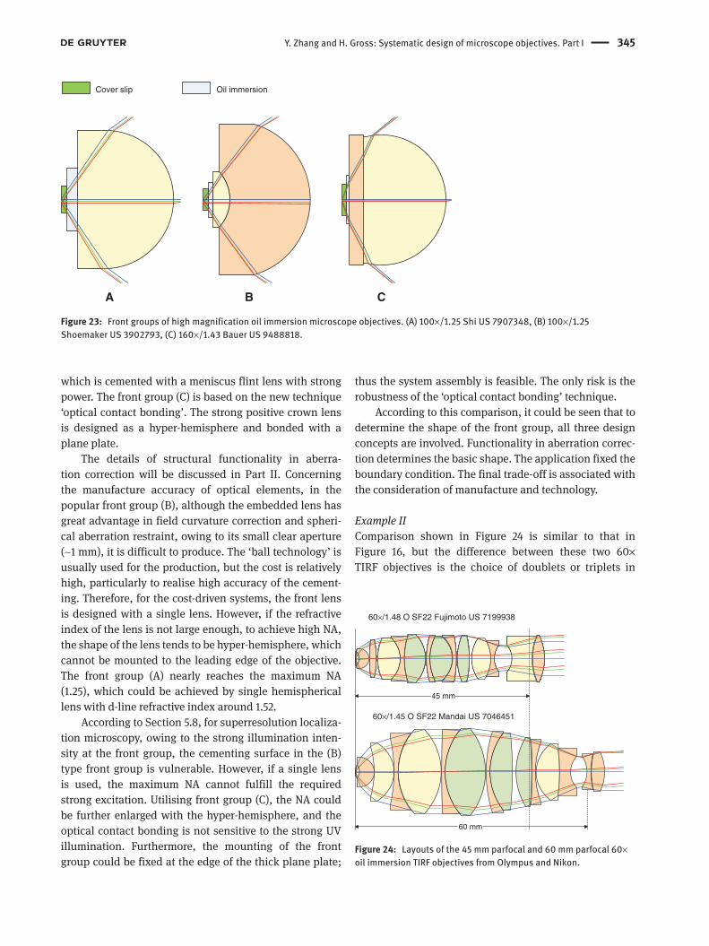
Y. Zhang and H. Gross: Systematic design of microscope objectives. Part I 345
which is cemented with a meniscus flint lens with strong power. The front group (C) is based on the new technique ‘optical contact bonding’. The strong positive crown lens is designed as a hyper-hemisphere and bonded with a plane plate.
The details of structural functionality in aberra-tion correction will be discussed in Part II. Concerning the manufacture accuracy of optical elements, in the popular front group (B), although the embedded lens has great advantage in field curvature correction and spheri-cal aberration restraint, owing to its small clear aperture (~1 mm), it is difficult to produce. The ‘ball technology’ is usually used for the production, but the cost is relatively high, particularly to realise high accuracy of the cement-ing. Therefore, for the cost-driven systems, the front lens is designed with a single lens. However, if the refractive index of the lens is not large enough, to achieve high NA, the shape of the lens tends to be hyper-hemisphere, which cannot be mounted to the leading edge of the objective. The front group (A) nearly reaches the maximum NA (1.25), which could be achieved by single hemispherical lens with d-line refractive index around 1.52.
According to Section 5.8, for superresolution localiza-tion microscopy, owing to the strong illumination inten-sity at the front group, the cementing surface in the (B) type front group is vulnerable. However, if a single lens is used, the maximum NA cannot fulfill the required strong excitation. Utilising front group (C), the NA could be further enlarged with the hyper-hemisphere, and the optical contact bonding is not sensitive to the strong UV illumination. Furthermore, the mounting of the front group could be fixed at the edge of the thick plane plate;
thus the system assembly is feasible. The only risk is the robustness of the ‘optical contact bonding’ technique.
According to this comparison, it could be seen that to determine the shape of the front group, all three design concepts are involved. Functionality in aberration correc-tion determines the basic shape. The application fixed the boundary condition. The final trade-off is associated with the consideration of manufacture and technology.
Example IIComparison shown in Figure 24 is similar to that in Figure 16, but the difference between these two 60× TIRF objectives is the choice of doublets or triplets in
A B C
Cover slip Oil immersion
Figure 23: Front groups of high magnification oil immersion microscope objectives. (A) 100×/1.25 Shi US 7907348, (B) 100×/1.25 Shoemaker US 3902793, (C) 160×/1.43 Bauer US 9488818.
45 mm
60 mm
60×/1.48 O SF22 Fujimoto US 7199938
60×/1.45 O SF22 Mandai US 7046451
Figure 24: Layouts of the 45 mm parfocal and 60 mm parfocal 60× oil immersion TIRF objectives from Olympus and Nikon.

346 Y. Zhang and H. Gross: Systematic design of microscope objectives. Part I
correcting spherical and chromatic aberrations. Both these two systems are apochromatic corrected for visible range from g-line to C-line and utilised vignetting for field correction.
The different parfocal length determines the mechan-ical dimension to fill lenses. The 60×/1.48 45 mm parfo-cal objective from Olympus used two cemented triplets in the middle group, whereas the 60×/1.45 60 mm parfocal objective utilised four doublets. These two setups have similar functionality in spherical and chromatic aberra-tion correction. But the triplet setup could relatively save space (also beneficial from the stronger front lens).
The selection of cemented doublets or triplets also highly depends on the coating technique of the manufac-turers. Because of the strong veiling glare generated by the air–glass interface, if excellent antireflection cannot be realised by coating, the air–glass interface with strong curvature should be avoided. Consequently, except the functionality of aberration correction, the cemented tri-plets utilised in the high-performance objectives are typi-cally designed with stronger inner cemented surface and flatter outer surfaces. On the contrary, if the veiling glare could be controlled by coating, utilising cemented dou-blets instead of triplets could introduce additional degree of freedom for correction, which is advantageous in relax-ing the system sensitivity.
7 Conclusion
As the basic step of modular analysis and microscope objectives synthesis, the systematic review of modern systems and a new systematic classification have been implemented. Six-zones-classification based on etendue, seven classes of chromatic correction, seven classes of field correction, five classes of working distance exten-sion, four types of correction and strategies of vendors in parfocal length and tube lens selection have been sorted systematically, which is helpful to understand the system complexity.
Based on the classification, following the historical review, impacts of applications and manufacture and technology considerations are summarised. The phe-nomenological Epoché could be operated by decoupling these two factors, and thus, we could concentrate on the functionality of lens modules in aberration correc-tion, which will be discussed in Part II. For the users of microscope, understanding the impact of applications is also helpful to evaluate the complexity and cost of their setup.
References[1] A. H. Bennett, J. Opt. Soc. Am. 33, 123–128 (1943).[2] H. Beyer, in ‘Handbuch der Mikroskopie’, (VEB Verlag Technik,
Berlin, 1988) pp. 13–23.[3] H. Gross, F. Blechinger and B. Achtner, in ‘Handbook of Optical
Systems’, (Survey of Optical Instruments, Wiley, Weinheim, 2008).[4] H. Boegehold, in ‘Das optische System des Mikroskops’, (VEB
Verlag Technik, Berlin, 1958).[5] W. Klein, Jahrbuch für Optik und Feinmechanik. 47–86 (1976).[6] H. Riesenberg, in ‘Handbuch der Mikroskopie’, (VEB Verlag
Technik, Berlin, 1988) pp. 24–107.[7] B. G. Broome, Proc. SPIE 10263, 102630H (1992).[8] H. Takenaka, Proc. SPIE 0554 (1986).[9] A. Miks and J. Novak, Appl. Opt. 49, 3403–3410 (2010).
[10] Frolov, J. Opt. Tech. 69, 614 (2002).[11] H. C. Claussen, Appl. Opt. 3, 993–1003 (1964).[12] Y. Zhang and H. Gross, Proc. SPIE 10590, 105901G (2017).[13] E. Husserl, in ‘The Paris Lectures’, (Springer, Netherlands,
Den Haag, 1964).[14] D. Shafer, in ‘My 50 Years of Optical Design Using Husserl’s
Phenomenology’, (Rochester, 2016).[15] H. Boegehold, US 1578259 (1926).[16] C. Schulz and C. Schumann, DE102017108595 (2018).[17] H. Boegehold, US 2206155 (1940).[18] W. Klein, US 3524694 (1970).[19] A. H. Shoemaker, US 3700311 (1972).[20] W. Klein, US 3537773 (1970).[21] A. Taira, US 3744881 (1973).[22] A. Taira, US 3806231 (1974).[23] M. Matsubara, US 3925910 (1975).[24] W. Klein, US 3176583 (1965).[25] T. Tojyo, US 4059342 (1977).[26] K. Yonekubo, US 4174151 (1977).[27] T. Tojyo, US 4279477 (1981).[28] Y. Saito, US 5530590 (1996).[29] R. Shi, US 7349162 (2008).[30] T. Kimura, JP S60-63512 (1985).[31] T. Togino, JP S62-49313 (1987).[32] S. Kashima, JP H05-196875 (1993).[33] I. Ito, US 6181480 (2001).[34] K. Arisawa, US 6016226 (2000).[35] Y.-H. Chuang, D. Shafer and J. J. Armstrong, US 7245438 (2007).[36] R. Wartmann, US 9645380 (2014).[37] T. Kasahara, US 9323036 (2013).[38] K. Abe, US 9939622 (2016).[39] R. Shi, US 7672057 (2010).[40] Carl Zeiss Microscopy GmbH, Objectives from Carl Zeiss
Exeeding your Expectations (2007).[41] K. H. Schade, P. Euteneuer and A. Müller-Rentz, Mitteilungenfür
Wissenschaft und Technik, (Wetzlar, 1998).[42] C. Metz, Zeitschr. für wiss. Mikroskopie. 37, 49–52 (1920).[43] T. Suzuki, US 5659425 (1997).[44] K. Watanabe, JP 2002-098903 (2002).[45] K. Yamaguchi, US 6519092 (2003).[46] N. Murayama and Y. Shimizu, US 5757552 (1995).[47] K. Arisawa, JP H04-220615 (1992).[48] S. F. Gibson and F. Lanni, J. Opt. Soc. Am. A. 9, 154–166 (1992).[49] L. Alvarez, US 3305294 (1967).

Y. Zhang and H. Gross: Systematic design of microscope objectives. Part I 347
[50] J. Babington, Proc. SPIE 9626, 962615 (2015).[51] T. Nobis, US 9696536 (2016).[52] I. Fahlbusch and G. Herbst, US 8988797 (2011).[53] Y. Ouchi, US 6366398 (1996).[54] R. Wartmann, DE 102009037743 (2009).[55] K. Abe, US 9746658 (2016).[56] T. Tojyo, US 4232941 (1977).[57] K. Arisawa, JP H05-196873 (1993).[58] J. L. Smith, The Inverted Microscope (a New Form of Microscope)
American Journal of Science and Art, 2nd series, Vol. XIV, (1852).[59] M. Akahane, US 20170184830 (2015).[60] M. Minsky, US 3013467 (1961).[61] P. Davidovits and M. D. Egger, US 3643015 (1972).[62] K. Carlsson, et al., Opt. Lett. 10, 53–55 (1985).[63] J. B. Pawley, in ‘Handbook of Biological Confocal Microscopy’,
(Springer, Boston, MA, 2006).[64] T. Wilson, ‘Confocal Microscopy’, (Academic Press, New York,
1990).[65] S. Kashima, US 5406421 (1992).[66] M. Matthae and G. Herbst, US 20130100537 (2013).[67] S. Kashima, US 7042648 (2003).[68] T. Suzuki, US 5132845 (1990).
Yueqian ZhangInstitute of Applied Physics, Friedrich Schiller University Jena, Albert-Einstein-Str. 15, 07745 Jena, [email protected]
Yueqian Zhang did his undergraduate study in Optical Engineering at Zhejiang University, Hangzhou, China. He received his Master degree in Photonics from Friedrich-Schiller-Universität Jena, Germany, in 2015. Since 2016, he has been working in the Optical Design Group at the Institute of Applied Physics in Friedrich-Schiller-Universität Jena. His research interests are classical system design, microscopic application and system development.
Herbert GrossInstitute of Applied Physics, Friedrich Schiller University Jena, Albert-Einstein-Str. 15, 07745 Jena, Germany
Herbert Gross studied Physics at the University of Stuttgart. He received his PhD on Laser Simulation in 1995. He joined Carl Zeiss in 1982 where he worked as a scientist in optical design, modelling, and simulation. From 1995 to 2010, he headed the central depart-ment of optical design and simulation. Since 2012, he has been a professor at the University of Jena in the Institute of Applied Physics and holds a chair of Optical System Design. His main working areas are physical optical simulations, beam propagation, partial coher-ence, classical optical design, aberration theory, system develop-ment, and metrology. He was editor and main author of the book series ‘Handbook of Optical Systems’.