z ote technical note tech - maine.gov
TRANSCRIPT

z
Performance Assessment of the DeTect™ HARRIER® X-Band Aircraft Detection Lighting System (ADLS) James Patterson, Jr. July 2018 DOT/FAA/TC-TN17/58 This document is available to the U.S. public through the National Technical Information Services (NTIS), Springfield, Virginia 22161. This document is also available from the Federal Aviation Administration William J. Hughes Technical Center at actlibrary.tc.faa.gov.
U.S. Department of Transportation Federal Aviation Administration
ote
tech
nica
l no
te t
ech

NOTICE
This document is disseminated under the sponsorship of the U.S. Department of Transportation in the interest of information exchange. The United States Government assumes no liability for the contents or use thereof. The United States Government does not endorse products or manufacturers. Trade or manufacturer's names appear herein solely because they are considered essential to the objective of this report. The findings and conclusions in this report are those of the author(s) and do not necessarily represent the views of the funding agency. This document does not constitute FAA policy. Consult the FAA sponsoring organization listed on the Technical Documentation page as to its use. This report is available at the Federal Aviation Administration William J. Hughes Technical Center’s Full-Text Technical Reports page: actlibrary.tc.faa.gov in Adobe Acrobat portable document format (PDF).

Technical Documentation Page 1. Report No.
DOT/FAA/TC-TN17/58 2. Government Accession No. 3. Recipient's Catalog No.
4. Title and Subtitle PERFORMANCE ASSESSMENT OF THE DETECT™ HARRIER® X-BAND AIRCRAFT DETECTION LIGHTING SYSTEM (ADLS)
5. Report Date July 2018
6. Performing Organization Code ANG-E261
7. Author(s) James Patterson, Jr.* and Garrison Canter**
8. Performing Organization Report No.
9. Performing Organization Name and Address 10. Work Unit No. (TRAIS) Federal Aviation Administration* SRA International, Inc.** William J. Hughes Technical Center A CSRA Company Aviation Research Division 1201 New Road Airport Safety R&D Section Suite 242 Atlantic City International Airport, NJ 08405 Linwood, NJ 08221
11. Contract or Grant No.
12. Sponsoring Agency Name and Address U.S. Department of Transportation Federal Aviation Administration Airport Engineering Division 800 Independence Avenue SW Washington, DC 20591
13. Type of Report and Period Covered Technical Note
14. Sponsoring Agency Code AAS-100
15. Supplementary Notes Mike DiPilato (FAA Airport Technology Research and Development Branch) and Joe Healey (SRA International, Inc.) provided technical support during this performance assessment. 16. Abstract Federal Aviation Administration (FAA) Airport Technology Research and Development Branch (ATR) personnel conducted a performance assessment of the X-band radar version of the HARRIER® Aircraft Detection Lighting System (ADLS) developed by DeTect™, Inc. The purpose of this assessment was to determine if the DeTect HARRIER ADLS meets the ADLS requirements specified in Chapter 14 of FAA Advisory Circular (AC) 70/7460-1L, “Obstruction Marking and Lighting.” FAA ATR personnel assessed a DeTect HARRIER X-band ADLS installed by the Public Service Electric and Gas Company on transmission towers near Aeroflex-Andover Airport (12N), located in Andover, New Jersey. This performance assessment, consisting of demonstrations, flight testing, and data analysis was conducted on June 24, 2016. In the performance assessment, a series of flight patterns were flown against the DeTect HARRIER ADLS to demonstrate whether it could meet the FAA performance requirements specified in AC 70/7460-1L. The DeTect HARRIER X-band ADLS performed according to the manufacturer’s specifications and met the performance requirements identified in AC 70/7460-1L. 17. Key Words
Aircraft detection lighting system (ADLS), Obstruction light control, Obstruction lighting, DeTect™ HARRIER
18. Distribution Statement
This document is available to the U.S. public through the National Technical Information Service (NTIS), Springfield, Virginia 22161. This document is also available from the Federal Aviation Administration William J. Hughes Technical Center at actlibrary.tc.faa.gov.
19. Security Classif. (of this report) Unclassified
20. Security Classif. (of this page) Unclassified
21. No. of Pages 53
22. Price
Form DOT F 1700.7 (8-72) Reproduction of completed page authorized.

iii
TABLE OF CONTENTS
Page
EXECUTIVE SUMMARY vii
INTRODUCTION 1
Purpose 1 Background 1 Objectives 2
THE ADLS STANDARDS 2
HARRIER ADLS CHARACTERISTICS AND SPECIFICATIONS 4
HARRIER ADLS Operational Description 5 HARRIER ADLS Radar Description 6 HARRIER ADLS Radar Controller Data System Description 7 HARRIER ADLS Perimeters 8 HARRIER ADLS Obstruction Lighting Control System Description 9 The PSE&G ADLS Display 10 HARRIER ADLS Fail-Safe Design 11
DETECT SYSTEM INSTALLATION DESCRIPTION AT 12N 12
THE FAA TESTS OF THE HARRIER ADLS 19
The FAA Flight Assessment 19 The FAA Component Failure Assessment 21
RESULTS 21
Basic Function Assessment 22 Detection Performance Assessment 23 Component Failure Assessment 37
CONCLUSIONS 38
REFERENCES 38
APPENDICES
A—Advisory Circular 70/7460-1L, Chapter 14, Aircraft Detection Lighting Systems B— HARRIER Aircraft Detection Lighting System Information
C—Intelligent Grid Interface Node-Enterprise to Field® System Technical Data Sheet

iv
LIST OF FIGURES
Figure Page
1 Required ADLS Detection Coverage 4 2 HARRIER ADLS Connected to Other ADLS Components 5 3 HARRIER ADLS Logic Overview 6 4 DeTect X-Band ADLS Radar With Radome Enclosure 7 5 Unprocessed Radar Image and Radar Image Processed by HARRIER Server 8 6 HARRIER ADLS Perimeters 9 7 DigitaLogic IGIN-EFS Obstruction Lighting Control System 10 8 The PSE&G ADLS System Display 11 9 The PSE&G Susquehanna-Roseland Transmission Line 12 10 The PSE&G ADLS Installation Sites at DEWA, 12N, and Montville 13 11 Andover ADLS Site Distance to Roseland Substation 14 12 Radar Locations Near 12N 15 13 Transmission Line Obstruction in Relation to 12N 16 14 The HSR-02 Installed on Transmission Tower 53/5 16 15 The DCU Installed on Transmission Tower 17 16 The FAA Type L-864/L-865 Obstruction Lights Controlled by the HARRIER ADLS 17 17 The 100-ft AGL Viewsheds: Radars HSR-01 and HSR-02 18 18 The 250-ft AGL Viewsheds: Radars HSR-01 and HSR-02 18 19 The 500-ft AGL Viewsheds: Radars HSR-01 and HSR-02 19 20 Cessna 172 Used for the Flight Assessment 20 21 The GPS Flight Track Data From the Aircraft 20 22 Flight Assessment as Observed on PSE&G ADLS Display 22 23 HARRIER ADLS Cumulative Radar Tracks Overlaid on the Aircraft’s GPS Track 23 24 Aircraft Takes Off Inside Warning Zone and Flies Directly Over Transmission Lines 26 25 Flights Directly Through the Warning Zone to the Northeast and South 27 26 Continuation of Flight Directly Through the Warning Zone to the Northeast and South 28 27 Flight Through the Warning Zone With Turns, Exiting to the East 29 28 Flight Adjacent to the Transmission Lines, Exiting Warning Zone to the Northwest 30 29 Flight Adjacent to the Transmission Lines, Exiting Warning Zone to the Southeast 31 30 Flight Directly Through the Warning Zone to the Northwest 32 31 Descending Flight Into the Warning Zone 33 32 Circling Flight Within the Warning Zone 34 33 First Flight Over the Obstruction and Landing Inside the Warning Zone 35 34 Second Flight Over the Obstruction and Landing Inside the Warning Zone 36

v
LIST OF TABLES Table Page 1 The GPS Coordinates of DeTect ADLS Radars Near 12N 15
vi
LIST OF ACRONYMS
12N Aeroflex-Andover Airport AC Advisory Circular ADLS Aircraft detection lighting system AGL Above ground level ATR Airport Technology Research and Development Branch CFR Code of Federal Regulations CMMS Computerized maintenance management system DCU Drive control unit DEWA Delaware Water Gap National Recreation Area FAA Federal Aviation Administration FCC Federal Communications Commission GPS Global positioning system HSR HARRIER® Surveillance Radar IGIN-EFS Intelligent Grid Interface Node-Enterprise to Field System® NM Nautical mile PSE&G Public Service Electric and Gas Company SCADA Supervisory control and data acquisition SQL Structured query language U.S. United States

vii/viii
EXECUTIVE SUMMARY
Federal Aviation Administration (FAA) Airport Technology Research and Development Branch (ATR) personnel conducted a performance assessment of the X-band radar version of the HARRIER® Aircraft Detection Lighting System (ADLS) developed by DeTect™, Inc. The purpose of this assessment was to determine if the X-band DeTect HARRIER ADLS meets the ADLS requirements specified in Chapter 14 of FAA Advisory Circular (AC) 70/7460-1L, “Obstruction Marking and Lighting.” ADLSs continuously monitor the airspace around an obstruction or group of obstructions for aircraft. When the ADLS detects an aircraft in its airspace, the system sends an electronic signal to the lighting control unit, which turns on the lights. Once the aircraft clears the obstruction area and there is no longer a risk of collision, the ADLS turns off the lights, and the system returns to standby mode. The United States has experienced a steady increase in the number of applications for construction of telecommunication towers and wind turbines. Any temporary or permanent structure, including telecommunication towers and wind turbines, that exceeds an overall height of 200 feet (61 meters) above ground level or exceeds any obstruction standard contained in Title 14 Code of Federal Regulations Part 77, “Safe, Efficient Use, and Preservation of the Navigable Airspace,” should be marked and/or lighted with FAA-approved paint markings or lighting fixtures to ensure that they are visible to pilots at night. Due to the number of existing telecommunication towers and wind turbines, combined with expected future construction, the number of obstructions that have these required lighting fixtures has greatly increased. The light generated by the increased number of fixtures has created a light pollution nuisance to residents living near these obstructions. Using an ADLS could have a positive impact on this problem by limiting the amount of time light fixtures are active while still providing a sufficient level of safety for pilots operating at night in the vicinity of these obstructions.
FAA ATR personnel assessed the DeTect HARRIER X-band system installed by the Public Service Electric and Gas Company on transmission towers near Aeroflex-Andover Airport (12N), located in Andover, New Jersey. This performance assessment, consisting of demonstrations, flight testing, and data analysis was conducted on June 24, 2016. In the performance assessment, a series of flight patterns were flown against the DeTect HARRIER system to demonstrate whether it could meet the FAA performance requirements specified in AC 70/7460-1L. The DeTect HARRIER X-band system performed according to the manufacturer’s specifications and met the performance requirements identified in Chapter 14 of AC 70/7460-1L.

1
INTRODUCTION
PURPOSE.
Federal Aviation Administration (FAA) Airport Technology Research and Development Branch (ATR) personnel conducted a performance assessment of the X-band radar version of the HARRIER® aircraft detection lighting system (ADLS) developed by DeTect™, Inc. The purpose of this assessment was to determine if the X-band Harrier ADLS meets the ADLS requirements specified in Chapter 14 of FAA Advisory Circular (AC) 70/7460-1L, “Obstruction Marking and Lighting.” [1] BACKGROUND.
In recent years, several companies have developed ADLSs that monitor the airspace around an obstruction or group of obstructions to automatically turn the obstruction lighting on or off as needed. Such systems continuously monitor the airspace around their location. When the ADLS detects an aircraft in its airspace, the system sends an electronic signal to the lighting control unit, which turns on the lights. Once the aircraft clears the obstruction area and there is no longer a risk of collision, the ADLS turns the lights off and the system returns to standby mode. These ADLSs are typically (1) mounted directly on the obstruction, (2) positioned on a dedicated tower close to the obstruction, or (3) mounted on a stand-alone structure located in the vicinity of the obstruction at an optimized vantage point to ensure that the sensor can cover the entire volume of airspace around the obstruction. In addition to controlling the obstruction lighting, some vendors have suggested using supplemental warning tools, such as an audible warning message or supplemental lighting, thereby providing an additional warning to the pilots that they are operating in close proximity to an obstruction. The United States (U.S.) has experienced a steady increase in the number of applications for construction of telecommunication towers and wind turbines, partially because of government mandates to improve the nation’s emergency communication network and to increase the amount of renewable energy generation. These telecommunication towers and wind turbines have become prominent throughout the U.S. Projections show that the accelerated rate of construction will continue well into the next decade. Any temporary or permanent structure, including these telecommunication towers and wind turbines that exceeds an overall height of 200 feet (ft) (61 meters (m)) above ground level (AGL) or exceeds any obstruction standard contained in Title 14 Code of Federal Regulations (CFR) Part 77, “Safe, Efficient Use, and Preservation of the Navigable Airspace,” [2] should be marked and/or lighted with FAA-approved paint markings or lighting fixtures to ensure that they are visible to pilots. Due to the number of existing telecommunication towers and wind turbines, combined with the expected construction of new structures, the number of obstructions that have FAA-required light fixtures has greatly increased. As a result, the increased number of light fixtures has created a light pollution nuisance to residents living near these obstructions. Using an ADLS could mitigate this problem while still providing a sufficient level of safety for pilots operating at night in the vicinity of these obstructions. From 2011 to 2016, ATR personnel have worked closely with several ADLS vendors to better understand the technologies, capabilities, and performance level that would be necessary to

2
safely integrate this concept into the National Airspace System. One major milestone achieved during the development of the ADLS standards was to enable the sensors to detect aircraft beyond the required 3 nautical miles (NM) from the obstruction. This would ensure that the lighting was on and the pilot was able to visually acquire the lights 3 NM away from the obstruction. The 3-NM visibility requirement is important because it ties directly to the inflight visibility requirements for a flight conducted under Visual Flight Rules. In 2013, ATR personnel first developed ADLS standards based on technical reviews, discussions, and ADLS flight tests in the U.S. and Canada. The FAA has since used these ATR-developed standards as the baseline against which new ADLSs, such as the HARRIER ADLS, were tested. The ATR-developed standards have since been integrated into AC 70/7460-1L as Chapter 14, “Aircraft Detection Lighting Systems,” which was published in December 2015 [1]. OBJECTIVES.
The overall objective of this assessment was to conduct a performance assessment of the HARRIER ADLS according to the requirements and standards for ADLSs in Chapter 14 of AC 70/7460-1L [1]. This technical note describes the performance assessment of the HARRIER ADLS installed and owned by the Public Service Electric and Gas Company (PSE&G) near Aeroflex-Andover Airport (12N) in Andover, New Jersey.
THE ADLS STANDARDS
Based on the result of research efforts conducted by FAA ATR personnel, Chapter 14 of AC 70/7460-1L is the first fully comprehensive set of standards for ADLSs published worldwide [1]. Earlier research efforts in Canada and the U.S. led to the development of a few sets of very ambiguous, vague descriptions of the technology, but they did not provide any specific guidance on the required range, coverage area, detection target size, or operational requirements. The following key ADLS operational requirements are introduced in Chapter 14 of AC 70/7460-1L [1]. Chapter 14, in its entirety, is included in appendix A.
1. “The system should be designed with sufficient sensors to provide complete detection coverage for aircraft that enter a three-dimensional volume of airspace, or coverage area, around the obstruction(s) (see figure 1), as follows:
a. Horizontal detection coverage should provide for obstruction
lighting to be activated and illuminated prior to aircraft penetrating the perimeter of the volume, which is a minimum of 3 NM (5.5 km) away from the obstruction or the perimeter of a group of obstructions.
b. Vertical detection coverage should provide for obstruction lighting to be activated and illuminated prior to aircraft penetrating the volume, which extends from the ground up to 1000 ft (304 m) above the highest part of the obstruction or group of obstructions, for all areas within the 3-NM (5.5-km) perimeter defined in above.
3
2. The ADLS should activate the obstruction lighting system in sufficient time to allow the lights to illuminate and synchronize to flash simultaneously prior to an aircraft penetrating the volume defined above. The lights should remain on for a specific time period, as follows:
a. For ADLSs capable of continuously monitoring aircraft while they
are within the 3-NM/1000-ft (5.5 km/304 m) volume, the obstruction lights should stay on until the aircraft exits the volume. In the event detection of the aircraft is lost while being continuously monitored within the 3-NM/1000 ft (5.5 km/304 m) volume, the ADLS should initiate a 30-minute timer and keep the obstruction lights on until the timer expires. This should provide the untracked aircraft sufficient time to exit the area and give the ADLS time to reset.
b. For ADLSs without the capability of monitoring aircraft targets in
the 3-NM/1000-ft (5.5-km/304-m) volume, the obstruction lights should stay on for a preset amount of time, calculated as follows:
i. For single obstructions: 7 minutes.
ii. For groups of obstructions: (the widest dimension in nautical miles + 6) x 90 seconds equals the number of seconds the light(s) should remain on.
3. In the event of an ADLS component or system failure, the ADLS should
automatically turn on all the obstruction lighting and operate in accordance with this AC as if it was not controlled by an ADLS. The obstruction lighting must remain in this state until the ADLS and its components are restored.
Special Note: As part of the Notice of Proposed Construction or Alteration (FAA Form 7460) filing process, the vendor must provide the FAA with a clear, acceptable explanation of how a component or system failure will be identified and addressed, and must also explain how possible interference will be identified and addressed. A statement such as the following should also be included verifying that the mitigation, monitoring, and fail-safe requirements provided in AC 7460-1L are being met:
“With regards to system component/system failure and interference of the radar signal, <insert vendor name> incorporates mitigation and monitoring systems which meet the fail-safe requirements for system performance according to FAA AC 70/7460-1L.”

4
4. In the event that an ADLS component failure occurs and an individual obstruction light cannot be controlled by the ADLS, but the rest of the ADLS is functional, that particular obstruction light should automatically turn on and operate in accordance with this AC as if it was not controlled by an ADLS, and the remaining obstruction lights can continue to be controlled by the ADLS. The obstruction lighting will remain in this state until the ADLS and its components are restored.
5. The ADLS’s communication and operational status shall be checked at least once every 24 hours to ensure both are operational.
6. Each ADLS installation should maintain a log of activity data for a period
of no less than the previous 15 days. This data should include, but not be limited to, the date, time, duration of all system activations/deactivations, track of aircraft activity, maintenance issues, system errors, communication and operational issues, lighting outages/issues, etc.” [1]
Figure 1. Required ADLS Detection Coverage [1]
Chapter 14 of AC 70/7460-1L also contains language that allows for ADLSs to have an optional voice/audio feature that transmits a low-power, audible warning message over an aviation frequency licensed by the Federal Communications Commission (FCC) in the MULTICOM/UNICOM frequency band to provide pilots additional information on the obstruction they are approaching [1]. The HARRIER ADLS does not offer this option, so these requirements do not apply to this assessment.
HARRIER ADLS CHARACTERISTICS AND SPECIFICATIONS
DeTect ADLS uses the company’s surveillance radars to provide automated aircraft tracking and lighting activation for wind farms and other obstruction(s), as described in Chapter 14 of AC 70/7460-1L [1]. The system is designed to connect to and control a supervisory control and data acquisition (SCADA) system at a wind farm or other obstruction(s). The system interfaces with lighting systems to keep obstruction warning lights powered off unless an aircraft is detected in

5
the vicinity of these obstructions. When aircraft are detected within the volume of airspace surrounding the obstruction(s), the obstruction warning lights are activated (turned on). When all aircraft have safely left the volume, the lights are deactivated (turned off). As with other ADLSs, the design of the HARRIER ADLS allows obstruction warning lights to remain off when aircraft are not in the obstruction vicinity. Appendices B and C contain additional information provided by DeTect regarding this system. The core systems of the HARRIER ADLS are the radar(s) and HARRIER radar controller data system(s). The other components of the complete ADLS installation include a SCADA obstruction lighting control system and computerized maintenance management system (CMMS). Figure 2 shows an example of the HARRIER ADLS installation described later in this technical note with the Intelligent Grid Interface Node Enterprise to Field System® (IGIN-EFS) developed by DigitaLogic, Inc.
Figure 2. HARRIER ADLS Connected to Other ADLS Components [3]
HARRIER ADLS OPERATIONAL DESCRIPTION.
A simplified diagram of the HARRIER ADLS logic is shown in figure 3. This system follows the general requirements described in AC 70/7460-1L [1]. The HARRIER ADLS operates as follows:
1. The ADLS receives input from the radar(s) and monitors a defined zone around the
obstructions (3.5-NM/1000-ft (6.5-km/304-m) volume or greater).

6
2. When aircraft are detected within the zone, the ADLS sends a signal to the obstruction lighting system, indicating the lights should be turned on.
a. When the last aircraft is tracked exiting the airspace volume (3.5-NM/1000-ft
(6.5-km/304-m) volume) and the aircraft count reaches 0, a 30-second countdown timer is activated.
b. If radar contact is lost with any aircraft within the monitored airspace volume, a
30-minute countdown timer is activated, and the lights remain on until this countdown expires.
3. When all countdown timers reach 0, the structured query language (SQL) database on the
ADLS radar controller data system generates a signal to turn off the obstruction lights. 4. A continuous system operation check is performed. If any components are not
operational, the obstruction lights will be activated. Note: For systems installed with two or more radars, light activation will occur if any of the radar units detects an aircraft.
Figure 3. HARRIER ADLS Logic Overview [3]
HARRIER ADLS RADAR DESCRIPTION.
The HARRIER ADLS can use 360-degree, 200-watt solid state S- or X-band Doppler radar sensor(s), which are referred to as HARRIER Surveillance Radars (HSRs) [4]. The HSR assessed by the FAA for this technical note was the X-band version. The HSR is designed to detect noncooperative aircraft in environments with large amounts of radar clutter, such as wind turbine blades at wind farms [4]. Figure 4 shows an example of the X-band version of the HSR with the radome enclosure installed on top of a transmission tower.

7
Figure 4. DeTect X-Band ADLS Radar With Radome Enclosure
DeTect states that the HSR has a detection range of up to 28 statute miles. The HSR can be set to detect aircraft based on user-defined perimeters (DeTect recommends setting a detection range of up to 10 miles). The system is powered by 110/220 volts of alternating current, 60/30 amperage service with uninterruptable power supply back-up and power conditioning (30 minutes) [4]. DeTect also offers an optional diesel generator to assist ensuring continuous operation. A required component of the HSR is the drive control unit (DCU). This is typically located at the base of the tower on which the radar is mounted. The DCU maintains a constant power and rate of revolution for the radar. The DCU also converts the signal from the radar into a format that can be sent via optical fibers to the server location for processing and target tracking. HARRIER ADLS RADAR CONTROLLER DATA SYSTEM DESCRIPTION.
The radar data from the HARRIER ADLS is processed and recorded by servers running a combination of DeTect’s proprietary software, known as Merlin®, and Microsoft® SQL Server® database software. The primary function of this system is to track aircraft targets and send signals to the obstruction lighting system indicating when obstruction lights can be turned on or off based on whether there are aircraft within a predefined perimeter around the obstruction. Figure 5(a) shows a 1-hour, time-lapsed image plot of raw aircraft radar tracks, while figure 5(b) shows radar tracks after being processed by the Merlin software [5]. This software also receives input from the obstruction lighting system regarding the status of these lights. All aircraft track data is recorded to the SQL database, which can be accessed by other monitoring systems, such as CMMS interface [6]. This database also provides a forensic tool in the event of system failure [6].

8
(a) (b) Figure 5. Unprocessed Radar Image (a) and Radar Image Processed by HARRIER Server (b) [5]
HARRIER ADLS PERIMETERS.
The HARRIER ADLS data system generates tracks for aircraft within a distance of 9 NM from each of the two radar units (shown as red and blue circles in figure 6). Within these overlapping 9-NM perimeters is a warning zone perimeter surrounding the obstruction(s). When aircraft enters this warning zone perimeter, the lights on the obstruction(s) are activated. The warning zone perimeter radius is set at a distance of 3.5 NM (6.5 km) or more from the obstruction(s). This 3.5-NM distance ensures the lights are activated by the time the aircraft reaches the 3.0-NM (5.5-km) perimeter defined in AC 70/7460-1L [1]. Examples of these perimeters are shown in figure 6.

9
Figure 6. HARRIER ADLS Perimeters
HARRIER ADLS OBSTRUCTION LIGHTING CONTROL SYSTEM DESCRIPTION.
The obstruction lighting control system used by the HARRIER ADLS described in this technical note was the DigitaLogic IGIN-EFS platform. The IGIN-EFS, shown in figure 7, performs the following functions [3]:
• Monitors and controls the obstruction lights. • Provides fail-safe applications in the event of component or network failure. • Sends customized data to a CMMS interface. • Provides 256-bit encryption authentication audit trail and other security features. • Generates maintenance and status reports on the current health of the system. • Generates text/email alarm notifications. The HARRIER ADLS and the IGIN-EFS systems together form the collective ADLS system for the PSE&G installation.

10
Figure 7. DigitaLogic IGIN-EFS Obstruction Lighting Control System [3]
THE PSE&G ADLS DISPLAY.
After processing, the data from the HARRIER ADLS and DigitaLogic IGIN-EFS can be sent to a consolidated display that allows the owner of the ADLS to monitor the system. The data sent from the HARRIER ADLS can be customized according to the needs of the obstruction owner, showing information such as real-time system health status, aircraft being tracked by the system, and lights-on status of the system. Figure 8 shows the display used by PSE&G for three HARRIER ADLS sites. In this example, the blue circles represent the 3.5-NM (6.5-km) warning zone perimeters for each ADLS site. Aircraft being tracked by the HARRIER ADLS are depicted as red triangles with trailing lines. Color-coded system status indicators are shown on the right side of the screen. The color green indicates systems are functioning normally, while red indicates an issue with the component shown. Also, on the right-hand side of the interface beneath each system status, there are counters showing the number of aircraft currently within each warning zone and the amount of time remaining until the obstruction lights will be turned off by the system.

11
Figure 8. The PSE&G ADLS System Display [6]
HARRIER ADLS FAIL-SAFE DESIGN.
The HARRIER ADLS and IGIN-EFS obstruction lighting control system are designed to provide fail-safe protection to ensure that if any errors or malfunctions occur, the obstruction lights are activated automatically. The lights will remain on until normal function is restored to all system components. The HARRIER ADLS is designed to keep obstruction lights on by default, and only a coordinated effort involving all systems and devices functioning in a normal state will allow the lights to be turned off [3]. The HARRIER ADLS includes system health monitoring, built in fail-safes, and target detection redundancy. The HARRIER ADLS can use two or more radar systems to provide overlapping radar coverage. If all radars lose radar contact with an aircraft within the warning zone, the lights will be activated. If weather is detected in the warning zone that could potentially interfere with system operation, the obstruction lights will be activated [4]. HARRIER ADLS software that runs on the SQL data system independently monitors the HARRIER software “heartbeat” [6]. In addition, HARRIER ADLS records internal processes on the SQL Server and communications between DeTect’s system and DigitaLogic’s lighting control system. DigitaLogic’s IGIN-EFS also independently monitors the HARRIER ADLS heartbeats between the radar controller data system and the DigitaLogic light activation system [3]. The IGIN-EFS will independently keep obstruction lights on if any issues are detected in the HARRIER ADLS and will record information about these events for later review. DeTect’s ADLS servers will send email alerts if there are any issues with the radar and send a daily email letting the owner know the system is online and operational [6].

12
DETECT SYSTEM INSTALLATION DESCRIPTION NEAR 12N
The HARRIER ADLS assessed in this technical note was installed by PSE&G as part of an ADLS on its 500-kilovolt (kV) Susquehanna-Roseland electrical transmission line. This transmission line runs from Berwick, Pennsylvania to Roseland, New Jersey. To address concerns about excessive lighting from the communities, PSE&G installed DeTect HARRIER ADLS technology at three sites in New Jersey: Delaware Water Gap National Recreation Area (DEWA), near 12N in Andover, New Jersey (referred to herein as the 12N site), and Montville, New Jersey (shown in figure 9) [6].
Figure 9. The PSE&G Susquehanna-Roseland Transmission Line [3]
The specific ADLS assessed by the FAA was located at the 12N site, which is shown highlighted with yellow circles in figure 10. The terrain features at the 12N site, which include mountains, ridges, valleys, and lakes, created a challenging environment for the radars. As a result of this complex terrain, two radars were installed at the 12N site to provide adequate coverage.

13
Figure 10. The PSE&G ADLS Installation Sites at DEWA, 12N, and Montville
As shown in figure 11, the servers for the ADLS were located approximately 28 NM from the 12N ADLS site at PSE&G’s Roseland substation. The servers communicate with each ADLS site via a fiber-optic network, which is incorporated into the transmission line facility. However, for the performance assessment, PSE&G set up a temporary workstation at 12N for ATR personnel to observe the system’s performance.

14
Figure 11. Andover ADLS Site Distance to Roseland Substation
Figure 12 shows an enlarged view of the 12N site and the two transmission towers where the HSRs for the ADLS were positioned. The radar installed on tower 54/2 was designated as HSR-01, and the radar installed on tower 53/5 was designated as HSR-02. Table 1 shows the global positioning system (GPS) coordinates and elevations of these two radar units.

15
Figure 12. Radar Locations Near 12N
Table 1. The GPS Coordinates of DeTect ADLS Radars Near 12N
Tower Number
Radar Designation
Ground Elevation
(MSL)
Installed Height (AGL)
Total Height (MSL) Latitude Longitude
54/2 HSR-01 604.860 ft 185 ft 789.862 ft 41° 1'20.68"N 74°43'37.55"W 53/5 HSR-02 724.828 ft 170 ft 894.828 ft 41° 1'38.16"N 74°44'18.79"W
MSL=Mean Sea Level As shown in figure 13, 12N was located within a short distance of the PSE&G transmission line in the departure and arrival path of aircraft operating from this airport. Therefore, HSR-01 was installed on tower 54/2 to provide direct line of sight to this airport to ensure the lights were activated when aircraft were taking off or landing. Figure 14 shows HSR-02 installed on tower 53/5. This tower was located at an elevation 120 ft higher than HSR-01 to provide additional radar area coverage.

16
Figure 13. Transmission Line Obstruction in Relation to 12N
Figure 14. The HSR-02 Installed on Transmission Tower 53/5
17
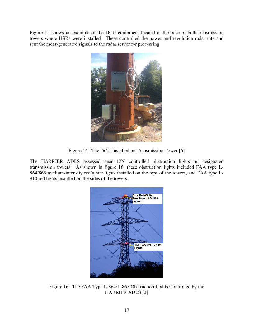
Figure 15 shows an example of the DCU equipment located at the base of both transmission towers where HSRs were installed. These controlled the power and revolution radar rate and sent the radar-generated signals to the radar server for processing.
Figure 15. The DCU Installed on Transmission Tower [6]
The HARRIER ADLS assessed near 12N controlled obstruction lights on designated transmission towers. As shown in figure 16, these obstruction lights included FAA type L-864/865 medium-intensity red/white lights installed on the tops of the towers, and FAA type L-810 red lights installed on the sides of the towers.
Figure 16. The FAA Type L-864/L-865 Obstruction Lights Controlled by the HARRIER ADLS [3]

18
Figures 17 through 19 show two-dimensional viewsheds generated by DeTect’s two radar units, HSR-01 and HSR-02, for the altitudes 100, 250, and 500 ft AGL. The radar coverage displays a range of 9 NM and includes DeTect’s 3.5-NM warning zone perimeter (shown in yellow), as well as the 3-NM FAA perimeter required by AC 70/7460-1L (shown as inner red circle) for reference. The left-hand images in figures 17 through 19 (figures 17(a), 18(a), and 19(a)) show the radar coverage for HSR-01, while the right-hand images (figures 17(b), 18(b), and 19(b)) show the radar coverage of HSR-02. As shown in figure 19, the warning zone was covered by HSR-02 at 500-ft AGL; however, there were portions in the southeast of the warning zone that could not be covered by either radar at 100 ft and 250 ft as a result of terrain obscuration. HSR-02 had a greater amount of coverage at all three altitudes compared to HSR-01; however, this difference was expected because HSR-01 was positioned at a lower elevation and was installed primarily to detect and track aircraft taking off from 12N.
(a) (b)
Figure 17. The 100-ft AGL Viewsheds: Radars HSR-01 (a) and HSR-02 (b)
(a) (b)
Figure 18. The 250-ft AGL Viewsheds: Radars HSR-01 (a) and HSR-02 (b)

19
(a) (b)
Figure 19. The 500-ft AGL Viewsheds: Radars HSR-01 (a) and HSR-02 (b)
THE FAA TESTS OF THE HARRIER ADLS
THE FAA FLIGHT ASSESSMENT.
To properly assess the performance of the HARRIER ADLS, ATR personnel conducted a series of flight patterns to assess the system’s response to aircraft operating around the warning zone (12N) at various altitudes, flight paths, speeds, etc. These were based on similar flight patterns conducted during previous FAA ADLS assessments [7 and 8]. Each pattern was designed to assess a specific ADLS parameter to determine if the system meets the requirements in AC 70/7460-1L [1]. The seven flight patterns are described below: 1. The aircraft took off from an airport inside the warning zone (12N) and flew directly
towards the transmission line obstruction. The intent of this pattern was to identify how quickly the HARRIER ADLS could detect the aircraft without the benefit of early detection as it became airborne and climbed towards the obstruction.
2. The aircraft flew to and over the transmission line obstruction at 750 ft AGL three times at various headings.
3. The aircraft flew adjacent to the transmission line obstruction at 750 ft AGL two times at
various headings. 4. The aircraft flew directly over the transmission line obstruction and radar sites at 1000 ft
AGL.
5. The aircraft flew to and over transmission line obstruction at least 1500 ft AGL and then steeply descended into the warning zone above the transmission lines.

20
6. The aircraft flew to and over the transmission line at an altitude less than 1000 ft AGL, completing several tight circles immediately over the obstruction and then exited the warning zone at a different heading from the entry heading.
7. The aircraft flew over the transmission lines at 1000 ft AGL and then descended and
landed at an airport inside the warning zone. ATR personnel used the Cessna® 172 shown in figure 20 to conduct the flight patterns. The aircraft was owned and flown by a pilot with a commercial pilot certificate. All flights were operated out of 12N. Figure 21 shows a Google Earth™ map image overlaid with the flight tracks (shown in blue) recorded by a GPS unit on board the aircraft. The yellow polygon represents the HARRIER ADLS warning zone perimeter, and the orange polygon represents the FAA’s required light activation perimeter.
Figure 20. Cessna 172 Used for the Flight Assessment
Figure 21. The GPS Flight Track Data From the Aircraft

21
THE FAA COMPONENT FAILURE ASSESSMENT.
In addition to the flight tests, ATR personnel also performed an assessment of the HARRIER ADLS’s fail-safe mechanisms designed to monitor and respond to certain component failures. This portion of the assessment was performed on the ground at the test site where the HARRIER ADLS and associated obstruction lighting could be observed. The specific parameters that were assessed, as addressed in AC 70/7460-1L [1], included the following: • The response of the HARRIER ADLS in the event there is a component or system
failure: the HARRIER ADLS should automatically turn on all the obstruction lighting and operate in accordance with AC 70/7460-1L [1] as if the lighting operated separately from the system. The lighting must remain in this state until the HARRIER ADLS and its components are restored.
• The response of the HARRIER ADLS in the event that an individual obstruction light cannot be controlled by the HARRIER ADLS, but the rest of the HARRIER ADLS is functional: that particular obstruction light should automatically turn on and operate in accordance with AC 70/7460-1L [1] as if it was not controlled by the HARRIER ADLS, while the remaining obstruction lights continue to be controlled by the HARRIER ADLS. The obstruction lighting must remain in this state until the HARRIER ADLS and its components are restored.
• Verification that the HARRIER ADLS’s communication and operational status was checked at least once every 24 hours to ensure both are operational.
• Verification that the HARRIER ADLS was able to detect an aircraft with a cross-sectional area of 1 square meter or more within the detection area.
• Verification that the HARRIER ADLS maintains a log of activity data for a period of no less than the previous 15 days. This data shall include, but not be limited to, the date, time, duration of all system activations/deactivations, track of aircraft activity, maintenance issues, system errors, communication and operational issues, lighting outages/issues, etc.
• Verification that the HARRIER ADLS components do not use devices identified in Title 47 CFR Part 15, “Radio Frequency Devices.” [9]
• If equipped with a voice/audio option, verify that the HARRIER ADLS operated within the performance specifications for the voice/audio option provided in Chapter 14 of AC 70/7460-1L [1]. (See appendix A.)
RESULTS
The performance assessment of the HARRIER ADLS was based on the specifications and criteria provided in AC 70/7460-1L. This AC lists specifications for basic functions, detection performance, and system output. The following sections document the performance of the

22
HARRIER ADLS along with the data collected during the performance assessment and discuss how it relates to the AC 70/7460-1L performance specifications. [1] BASIC FUNCTION ASSESSMENT.
Prior to beginning the performance assessment, ATR personnel first verified that the system was fully functional and running normally. ATR personnel verified that, without any aircraft present in the area, the system continuously scanned the area and kept the indicator lamp “off.” ATR personnel at the radar site monitored the PSE&G ADLS display and communicated with the ATR personnel on board the aircraft via a two-way radio. The ATR personnel at the radar site verified the system was tracking the aircraft as it entered the warning zone and confirmed that the system was showing the correct number of aircraft inside this zone. Figure 22 shows a screenshot of the flight track as it appeared during the assessment.
Figure 22. Flight Assessment as Observed on PSE&G ADLS Display
During the assessment flights, the HARRIER ADLS recorded radar tracks. These radar tracks were exported as Keyhole Markup Language files viewable in Google Earth. Figure 23 shows a record of the entire FAA assessment flight pattern. The dotted red lines represent the real-time tracks produced from the HARRIER ADLS, and the solid blue lines represent the tracks recorded by the GPS on board the aircraft.

23
Figure 23. HARRIER ADLS Cumulative Radar Tracks Overlaid on the Aircraft’s GPS Track
DETECTION PERFORMANCE ASSESSMENT.
To demonstrate that the HARRIER X-band ADLS was able to meet the detection performance requirements for an ADLS, ATR personnel conducted a series of flight patterns designed to assess the system’s detection capabilities. Because this ADLS was an operational system necessary for the safety of other aircraft, the lights could not be turned off by ATR personnel prior to each flight pattern when other aircraft were in the area. The obstruction lights were active for 83% of the duration of the ATR flight and turned off for 17% of this time. During two flight patterns, the FAA aircraft activated the obstruction lights, confirming the functioning of this portion of the system. Descriptions of the patterns and the results of the HARRIER ADLS’s detection capability are as follows: • Takeoff from an airport inside the warning zone.
The HARRIER ADLS was able to detect and track the aircraft within 20 seconds of the aircraft becoming airborne, a distance of approximately 0.2 NM from the departure end of Runway 3. The obstruction lights were activated prior to this pattern and remained on while the FAA aircraft was departing the warning zone. Figure 24 shows events 1-4 for this flight pattern.
• Flights to and over the transmission lines at 750 ft AGL three times at various headings.
The HARRIER ADLS was able to detect and track the aircraft each time it entered the warning zone and flew directly over the transmission line obstruction at 750 ft AGL. On

24
the first flights over the obstruction, the lights were activated when the aircraft was 3.3 NM from the transmission line. Radar contact was briefly lost with the aircraft shortly before exiting the FAA perimeter; however, the lights remained active during this period. The aircraft then crossed over the obstruction a second time heading southeast. Radar contact was again lost shortly before the aircraft exited the warning zone with the obstruction lights remaining on. Figures 25 and 26 show events 5-10 for these flight patterns. On the third flight over the obstruction, the lights were already activated prior to the FAA aircraft entering the warning zone; however, the HARRIER ADLS detected and tracked both aircraft. Radar contact was briefly lost as the FAA aircraft made several turns before leaving the warning zone, but the obstruction lights remained on during this period. Figure 27 shows events 11-14 for this flight pattern.
• The aircraft flew adjacent to the transmission lines at 750 ft AGL two times at various headings.
The HARRIER ADLS was able to detect and track the aircraft as it flew adjacent to the transmission line obstruction in two different directions at 750 ft AGL. For both of these patterns, the obstruction lights were activated by other aircraft prior to the FAA aircraft entering the warning zone; however, ATR personnel confirmed the aircraft was registered as being inside the warning zone. Figures 28 and 29 show events 15-22 for these flight patterns.
• The aircraft flew directly over transmission line obstruction and radar sites at 1000 ft AGL.
The HARRIER ADLS was able to detect and track the aircraft at a distance of 6.1 NM from the obstruction as it approached from the southeast at 1000 ft AGL. Figure 30 shows events 23-26 for this flight pattern.
• The aircraft flew to and over transmission line obstruction at least 1500 ft AGL and then steeply descended into the warning zone above the transmission lines.
The HARRIER ADLS was able to detect and track the aircraft as it descended from an altitude of 1500 ft AGL to 500 ft AGL. Radar contact was lost as the aircraft was exiting the warning zone to the southeast behind terrain; however the ADLS’s lost aircraft timer ensured the obstruction lights remained on. Figure 31 shows events 27-30 for this flight pattern.
• The aircraft flew to and over the transmission line at an altitude less than 1000 ft AGL, completed several tight circles immediately over the obstruction, and then exited the warning zone at a different heading from the entry heading.
The HARRIER ADLS detected the aircraft at a distance of 3.5 NM from the transmission line obstructions. The system was able to track the aircraft as it conducted four steep, circling turns within the warning zone over the radars and obstructions. Figure 32 shows events 31-34 for this flight pattern.

25
• The aircraft flew over the transmission lines at 1000 ft AGL, then descended and landed at an airport inside the warning zone.
The HARRIER ADLS was able to detect the aircraft and activate the obstruction lights when the aircraft reached a distance of 3.4 NM from the obstructions. The aircraft continued to be tracked as it flew directly over the obstruction and radars. Radar contact became intermittent as the aircraft descended in the traffic pattern for landing on Runway 3. The HARRIER ADLS turned off the obstruction lights within 90 seconds of the aircraft landing at 12N. Figures 33 and 34 show events 35-38 and 39-41, respectively, for this flight pattern.

26
Event 1:
• A
ircraft begins its takeoff from
inside the w
arning zone. •
Aircraft is not
detected. •
Lights are on prior to takeoff.
Event 2:
• Aircraft takes
off and is detected by radar.
• Aircraft is
registered w
ithin w
arning zone. • Lights rem
ain on.
Event 3:
• A
ircraft flies directly over the transm
ission lines and radar.
• A
ircraft continues to be tracked by radar.
• Lights rem
ain on.
Event 4:
• Aircraft exits
the warning
zone perimeter
heading southw
est. • Lights rem
ain on until the A
DLS
countdown
reaches zero.
Figure 24. Aircraft Takes O
ff Inside Warning Zone and Flies D
irectly Over Transm
ission Lines (Events 1-4)

27
Event 5:
• Aircraft
approaches the w
arning zone from
the southw
est. • Lights are off.
Event 6:
• Aircraft is
detected and tracked by the radar as it approaches the w
arning zone perim
eter. • Lights are
off.
Event 7:
• Aircraft
penetrates the w
arning zone perim
eter. • A
ircraft is registered inside w
arning zone. • Lights are
activated.
Event 8:
• The lights are on prior to the aircraft entering FA
A-
required perim
eter. • A
ircraft is tracked flying through the w
arning zone over the obstructions.
Figure 25. Flights D
irectly Through the Warning Zone to the N
ortheast and South (Events 5-8)

28
Event 9:
• A
ircraft completes
a turn within the
warning zone and
approaches the transm
ission lines from
the northeast. •
Aircraft briefly
lost and reacquired by the radar, activating the A
DLS tim
er. •
Lights remain on.
Event 10:
• A
ircraft flies over the transm
ission lines and exits the w
arning zone heading southw
est. •
Radar contact
is lost shortly before aircraft exits the w
arning zone. •
Lights remain
on.
Figure 26. Continuation of Flight D
irectly Through the Warning Zone to the N
ortheast and South (Events 9 and 10)

29
Event 11:
• A
ircraft approaches the w
arning zone from
the southwest
• Lights rem
ain on.
Event 12:
• A
ircraft is detected and tracked by the radar before reaching the w
arning zone. •
Lights remain
on.
Event 13:
• A
ircraft penetrates the w
arning zone perim
eter. •
Aircraft is
registered inside w
arning zone. •
Lights remain on.
Event 14:
• A
ircraft begins a series of turns before exiting the w
arning zone.
• R
adar contact is briefly lost at tim
es during the turns, activating the A
DLS tim
er. •
Lights remain
on.
Figure 27. Flight Through the Warning Zone W
ith Turns, Exiting to the East (Events 11-14)

30
Event 15:
• A
ircraft approaches the w
arning zone from
the east. •
Lights remain on.
Event 16:
• A
ircraft is detected by radar and is tracked before entering the w
arning zone. • Lights rem
ain on.
Event 17:
• A
ircraft penetrates the w
arning zone perim
eter and flies along the t ransm
ission line. •
Aircraft is
registered inside w
arning zone. •
Lights remain on.
Event 18:
• A
ircraft exits the w
arning zone to the northw
est. •
Lights remain
on.
Figure 28. Flight Adjacent to the Transm
ission Lines, Exiting Warning Zone to the N
orthwest (Events 15-18)

31
Event 19:
• A
ircraft approaches the w
arning zone from
the northw
est •
Lights remain
on.
Event 20:
• A
ircraft is detected by radar and is tracked before entering the w
arning zone.
• Lights rem
ain on.
Event 21:
• A
ircraft penetrates the w
arning zone perim
eter. •
Aircraft is
registered inside w
arning zone. •
Lights remain
on.
Event 22:
• A
ircraft exits the w
arning zone to the southeast.
• Lights rem
ain on.
Figure 29. Flight Adjacent to the Transm
ission Lines, Exiting Warning Zone to the Southeast (Events 19-22)

32
Event 23:
• A
ircraft approaches the w
arning zone from
the southeast.
• Lights rem
ain on.
Event 24:
• A
ircraft is detected and is tracked by radar.
• Lights rem
ain on.
Event 25:
• A
ircraft penetrates the w
arning zone perim
eter. •
Aircraft is
registered inside w
arning zone. •
Lights remain
on.
Event 26:
• A
ircraft exits the w
arning zone to the northw
est. •
Lights remain
on.
Figure 30. Flight Directly Through the W
arning Zone to the Northw
est (Events 23-26)

33
Event 27:
• A
ircraft approaches the w
arning zone from
the northw
est at 1500 ft A
GL.
• Lights are on.
Event 28:
• A
ircraft is detected and is tracked by radar.
• Lights are on.
Event 29:
• A
ircraft penetrates the w
arning zone perim
eter. •
Aircraft is
registered inside w
arning zone as it descends to 500 ft A
GL.
• Lights rem
ain on.
Event 30:
• A
ircraft makes
two 90-degree
turns before exiting w
arning zone to the southeast.
• R
adar contact is lost prior to aircraft exiting the zone.
• Lights rem
ain on.
Figure 31. D
escending Flight Into the Warning Zone (Events 27-30)

34
Event 31:
• A
ircraft approaches the w
arning zone from
the northw
est. •
Lights remain on.
Event 32:
• A
ircraft penetrates the w
arning zone perim
eter. •
Aircraft is
registered inside w
arning zone. •
Lights remain
on.
Event 33:
• C
ompletes four
steep turns over the transm
ission lines and radars.
• Lights rem
ain on.
Event 34:
• A
ircraft exits the w
arning zone to the east.
• Lights rem
ain on until A
DLS
countdown
timer reaches
zero.
Figure 32. Circling Flight W
ithin the Warning Zone (Events 31-34)

35
Event 35:
• A
ircraft approaches the w
arning zone from
the east. •
Lights are off.
Event 36:
• A
ircraft penetrates the w
arning zone perim
eter. •
Aircraft is
registered inside w
arning zone.
• Lights are activated.
Event 37:
• A
ircraft exits the w
arning zone to the east.
• R
adar contact w
ith aircraft lost.
• C
ountdown
timer begins.
• Lights rem
ain on.
Event 38:
• A
ircraft turns back tow
ards obstruction from
the west
and is reacquired by radar.
• Lights rem
ain on.
Figure 33. First Flight Over the O
bstruction and Landing Inside the Warning Zone (Events 35-38)

36
Event 39:
• A
ircraft penetrates the w
arning zone perim
eter from
the west.
• A
ircraft is registered inside w
arning zone. •
Lights remain
on.
Event 40:
• A
ircraft turns to fly directly over the transm
ission lines and enters the 12N
traffic pattern.
• Lights rem
ain on.
Event 41:
• A
ircraft lands at 12N
. •
Radar contact is
lost after landing.
• Lights rem
ain on until the A
DLS
countdown
reaches zero.
Figure 34. Second Flight Over the O
bstruction and Landing Inside the Warning Zone (Events 39-41)

37
COMPONENT FAILURE ASSESSMENT.
To demonstrate that the HARRIER X-band ADLS was able to meet the component failure requirements for an ADLS, ATR personnel conducted a series of activities designed to test the system’s component failure responses. Descriptions of the activities and the results of the HARRIER ADLS’s failure response are as follows: • Individual Component and Obstruction Light Control Failure
ATR personnel observed that when individual components of the HARRIER ADLS were disconnected or disabled, the ADLS automatically turned on all the obstruction lights as if the lights operated separately from the system. The obstruction lighting remained in this state until the HARRIER ADLS was returned to online status. Once the lighting system recognized the HARRIER ADLS’s “heartbeat,” which indicated the system was operating correctly, the lights were turned off.
• Communication and Status Monitoring
ATR personnel verified that the HARRIER ADLS communication and operational statuses were able to be checked at least once every 24 hours to ensure both were operational.
• Target Size
ATR personnel confirmed that the HARRIER ADLS could identify an object with a cross-sectional area of 1 square meter or more within the detection area. This was accomplished by flying an aircraft straight toward the HARRIER ADLS’s radar unit, and resulted in the system being able to detect the narrow profile of the aircraft.
• Activity Log
PSE&G and DeTect personnel demonstrated to the ATR personnel that the radar data could be stored for an indefinite amount of time, depending on the user’s requirement, which satisfies the 15-day requirement of AC 70/7460-1L [1].
• FCC Part 15 Compliance
Based on the documentation that DeTect personnel provided to ATR personnel, it was determined that the HARRIER ADLS components do not use FCC Part 15 devices [9]. Lighting control subsystems connected to the HARRIER ADLS used Part 15 components; however, these are not critical to the functioning of the ADLS itself.
• Audio/Voice Option
The DeTect ADLS does not currently offer a voice/audio option; therefore, this was not assessed. As stated in AC 70/7460-1L, this is not a required ADLS component [1].

38
CONCLUSIONS
The Federal Aviation Administration (FAA) Airport Technology Research and Development Section assessed the X-band radar version of the DeTect™ HARRIER® Aircraft Detection Lighting System (ADLS) installed and owned by the Public Service Electric and Gas Company on transmission towers in the vicinity of Aeroflex-Andover Airport, near Andover, New Jersey. A performance assessment consisting of demonstrations, flight testing, and data analysis was conducted on June 24, 2016. In this performance assessment, a series of flight patterns were flown against the DeTect HARRIER ADLS to demonstrate that it could meet the FAA’s performance requirements for an ADLS. The DeTect HARRIER X-band ADLS performed according to the manufacturer’s specifications and met the performance requirements specified in Chapter 14 of FAA Advisory Circular 70/7460-1L, “Obstruction Marking and Lighting.”
REFERENCES
1. Federal Aviation Administration (FAA), “Obstruction Marking and Lighting,” Advisory Circular 70/7460-1L, December 4, 2015.
2. United States (U.S.) Federal Register, Title 14 Code of Federal Regulations (CFR), Part 77, “Safe, Efficient Use, and Preservation of the Navigable Airspace,” U.S. Government Publishing Office, Washington, DC.
3. DigitaLogic, “IGIN-EFS (IGIN-Enterprise to Field System) - Advanced IT Platform for
ADLS,” November 2016.
4. DeTect, Inc., “Technical Data Sheet – HARRIER® ADLS,” April 2016. 5. DeTect, Inc., “Briefing – HARRIER ADLS,” 2015.
6. DeTect, Inc., “Summary of FAA ADLS Test,” June 2016.
7. Patterson, James, Jr., “Performance Assessment of the Laufer Wind Aircraft Detection
System as an Aircraft Detection Lighting System, FAA technical note DOT/FAA/TC-TN15/54, May 2016.
8. Patterson, James, Jr., “Performance Assessment of the Terma Obstruction Light Control System as an Aircraft Detection Lighting System” FAA technical note DOT/FAA/TC-TN16/41, June 2016.
9. U.S. Federal Register, Title 47 CFR, Part 15, “Radio Frequency Devices,” U.S.
Government Publishing Office, Washington, DC.

A-1
APPENDIX A—ADVISORY CIRCULAR 70/7460-1L, CHAPTER 14 AIRCRAFT DETECTION LIGHTING SYSTEMS1
CHAPTER 14. AIRCRAFT DETECTION LIGHTING SYSTEMS
14.1 Purpose. Aircraft Detection Lighting Systems (ADLS) are sensor-based systems designed to detect aircraft as they approach an obstruction or group of obstructions; these systems automatically activate the appropriate obstruction lights until they are no longer needed by the aircraft. This technology reduces the impact of nighttime lighting on nearby communities and migratory birds and extends the life expectancy of obstruction lights. 14.2 General Standards. 14.2.1 The system should be designed with sufficient sensors to provide complete detection coverage for aircraft that enter a three-dimensional volume of airspace, or coverage area, around the obstruction(s) (see Figure A-27 in Appendix A), as follows: 1. Horizontal detection coverage should provide for obstruction lighting to be activated and illuminated prior to aircraft penetrating the perimeter of the volume, which is a minimum of 3 NM (5.5 km) away from the obstruction or the perimeter of a group of obstructions. 2. Vertical detection coverage should provide for obstruction lighting to be activated and illuminated prior to aircraft penetrating the volume, which extends from the ground up to 1000 feet (304 m) above the highest part of the obstruction or group of obstructions, for all areas within the 3 NM (5.5 km) perimeter defined in subparagraph 14.2.1 1 above. 3. In some circumstances, it may not be possible to meet the volume area defined above because the terrain may mask the detection signal from acquiring an aircraft target within the 3 NM (5.5 km) perimeter. In these cases, the sponsor should identify these areas in their application to the FAA for further evaluation. 4. In some situations, lighting not controlled by the ADLS may be required when the 3 NM (5.5 km) perimeter is not achievable to ensure pilots have sufficient warning before approaching the obstructions. 14.2.2 The ADLS should activate the obstruction lighting system in sufficient time to allow the lights to illuminate and synchronize to flash simultaneously prior to an aircraft penetrating the volume defined above. The lights should remain on for a specific time period, as follows:
1 Federal Aviation Administration, “Obstruction Marking and Lighting,” Advisory Circular (AC) 70/7460-1L – Change 1, October 8, 2016.

A-2
1. For ADLSs capable of continuously monitoring aircraft while they are within the 3 NM/1,000 foot (5.5 km/304 m) volume, the obstruction lights should stay on until the aircraft exits the volume. In the event detection of the aircraft is lost while being continuously monitored within the 3 NM/1,000 foot (5.5 km/304 m) volume, the ADLS should initiate a 30-minute timer and keep the obstruction lights on until the timer expires. This should provide the untracked aircraft sufficient time to exit the area and give the ADLS time to reset. 2. For ADLSs without the capability of monitoring aircraft targets in the 3 nm/1,000 foot (5.5 km/304 m) volume, the obstruction lights should stay on for a preset amount of time, calculated as follows: a. For single obstructions: 7 minutes. b. For groups of obstructions: (the widest dimension in nautical miles + 6) x 90 seconds equals the number of seconds the light(s) should remain on. 14.2.3 Acceptance of ADLS applications will be on a case-by-case basis and may be modified, adjusted, or denied based on proximity of the obstruction or group of obstructions to airports, low-altitude flight routes, military training areas, or other areas of frequent flight activity. It may be appropriate to keep certain obstructions closest to these known activity areas illuminated during the nighttime hours, while the remainder of the group’s obstruction lighting is controlled by the ADLS. 14.2.4 Project sponsors requesting ADLS use should include in their application maps or diagrams indicating the location of the proposed sensors, the range of each sensor, and a visual indication showing how each sensor’s detection arc provides the full horizontal and vertical coverage, as required under paragraph 14.2.1. In the event that detection coverage is not 100 percent due to terrain masking, project sponsors should provide multiple maps or diagrams that indicate coverage at the affected altitudes. A sample diagram is shown in Figure A-27 in Appendix A. 14.2.5 Types of ADLS Component or System Failure Events. 1. In the event of an ADLS component or system failure, the ADLS should automatically turn on all the obstruction lighting and operate in accordance with this AC as if it was not controlled by an ADLS. The obstruction lighting must remain in this state until the ADLS and its components are restored. 2. In the event that an ADLS component failure occurs and an individual obstruction light cannot be controlled by the ADLS, but the rest of the ADLS is functional, that particular obstruction light should automatically turn on and operate in accordance with this AC as if it was not controlled by an ADLS, and the remaining obstruction lights can continue to be controlled by the ADLS. The obstruction lighting will remain in this state until the ADLS and its components are restored.

A-3/A-4
3. Complete light failure should be addressed in accordance with Chapter 2 paragraph 2.4. 14.2.6 The ADLS’s communication and operational status shall be checked at least once every 24 hours to ensure both are operational. 14.2.7 The ADLS should be able to detect an aircraft with a cross-sectional area of 1 square meter or more within the volume, as required in subparagraphs 14.2.1 1 and 14.2.1 2. 14.2.8 Each ADLS installation should maintain a log of activity data for a period of no less than the previous 15 days. This data should include, but not be limited to, the date, time, duration of all system activations/deactivations, track of aircraft activity, maintenance issues, system errors, communication and operational issues, lighting outages/issues, etc. 14.2.9 Operational Frequencies. 1. Unlicensed devices (including FCC Part 15) devices cannot be used for this type of system. 2. Any frequency used for the operation of ADLS must be individually licensed through the FCC. 14.3 Voice/Audio Option. 14.3.1 ADLS may include an optional voice/audio feature that transmits a low-power, audible warning message to provide pilots additional information on the obstruction they are approaching. 14.3.2 The audible transmission should be in accordance with appropriate FAA and FCC regulations. 14.3.3 The audible transmission should be over an aviation frequency licensed by the FCC and authorized under the Code of Federal Regulations Title 47- Part 87.483 (excluding 121.5 MHz). Note: Using air traffic control frequencies in the 117.975-MHz to 137-MHz frequency band is prohibited for this operation. 14.3.4 The audible message should consist of three quick tones, followed by a verbal message that describes the type of obstruction the system is protecting. Appropriate terms to be used include tower(s), wind turbine(s), or power line(s). 14.3.5 The audible message should be repeated three times or until the system determines the aircraft is no longer within the audible warning area defined in the following paragraph. 14.3.6 The audible message should be considered as a secondary, final warning and should be activated when an aircraft is within 1/2 NM (926 m) horizontally and 500 feet (152 m) vertically of the obstruction. The use of, or variation to, the audible warning zone may occur, depending on site-specific conditions or obstruction types.

B-1
APPENDIX B—HARRIER AIRCRAFT DETECTION LIGHTING SYSTEM INFORMATION

B-2

C-1
APPENDIX C— INTELLIGENT GRID INTERFACE NODE-ENTERPRISE TO FIELD® SYSTEM TECHNICAL DATA SHEET0.0.23.23.0.203222333

C-2