z soil 2d/3d, a pocket calculator · · 2010-10-08pocket calculator, since 1985, ... safety,...
TRANSCRIPT
Keywords: software tool, 3 dimensional, user-friendly, reliable, tested worldwide, pocket calculator, since 1985, Swiss made.
Thanks to people who knew how to share their motivations, their knowledge and their know-how with others, Civil Engineering has been keeping developing for over one hundred years. This article is dedicated to Z_SOIL ® 3D and its first designer, Prof. Dr. Thomas Zimmermann, who has been trying hard for more than 20 years to achieve his goal, that is: developing a reliable user-friendly high performance software tool to solve complex civil engineering problems, in an unified manner, specially in the field of soil-structure interaction. A few projects are shown hereafter to demonstrate that today Z_SOIL ® can be used as simply as a pocket calculator; and the aim of present and future developments in Z_SOIL ® remains: improving user-friendliness, reliability and performance.
Before getting to the heart of the matter, let me give you a short history. In 1986,
the first PC version of Z_SOIL ® (2D) was launched. At that time, I was on a training course at the Federal Institute of Technology of Lausanne (EPFL). In 1990, I used Z_SOIL ® for the first time during the preparation of my engineering diploma. In 1991, Prof. Th. Zimmermann and his staff started to develop a general user- friendly,three-dimensional PC calculation tool for soils and rocks, to assist civil engineers in day-to-day dimensioning. In 1993, this led to a partnership between well-known civil engineering companies, ZACE Services Ltd and the Swiss Federal Institute of Technology(EPFL). For several years, the 3-dimensional developments were then available exclusively to this restricted circle of partners, un til a commercial version of Z_SOIL ® 3D was developed, which since recently is free from any exclusive rights and is available to anybody.
Since 1994, I have been an active participant in the practical development of Z_SOIL ® 3D. My main goal was to contribute to the pre and post-processing tools and to develop training methods. Within the B.E.T. SARF company, I offer now practical training and consulting services on Z_SOIL ® 3D, worldwide.
Z_SOIL ® 2D/3D, a pocket calculator
Jean – Luc SARF* *CEO of the B.E.T. Jean L. SARF,
Rue du Lignolat 48, CH-1170 Aubonne Phone: +41 (0)21 616 01 63, [email protected]
17
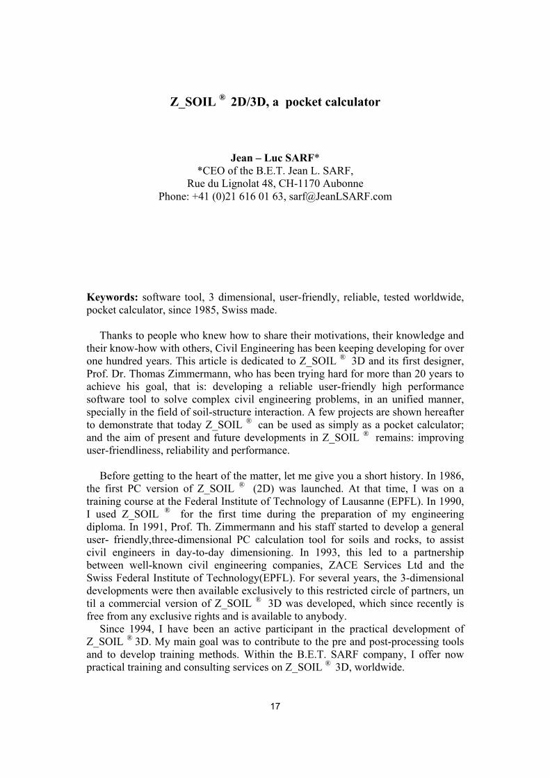
The following figure summarizes what Z_SOIL ® 3D represents for me: a time saving pocket calculator. Program Z_SOIL ® , registered in 1985, has been keeping developing with time. It offers a top-level hotline, well designed interfaces and user manuals, and capabilities which are in continuous evolution. Many users also take advantage of dedicated functions, pertinent to their specific applications, to increase speed and user-friendliness. Today, the program has gained worldwide recognition for its quality. It is used daily in engineering practice and in the academic world.
Welcome to Z-SOIL pocket calculator
Swiss made
Pre-processor Post-processor Analysis module
by Jean-L. SARF
Time is Money !
In the years 1994 - 1997, complex three-dimensional non-linear numerical analyses required weeks of work, starting from model creation to synthesis report, for example to analyze the time-dependent behavior of a dam. Today, thanks to very performing pre-processing tools, things have changed. Now, after analysing the problem to solve and preparing a first design of the numerical model, only a few hours are necessary to create a geometrically complex numerical model with Z_SOIL ® 3D.
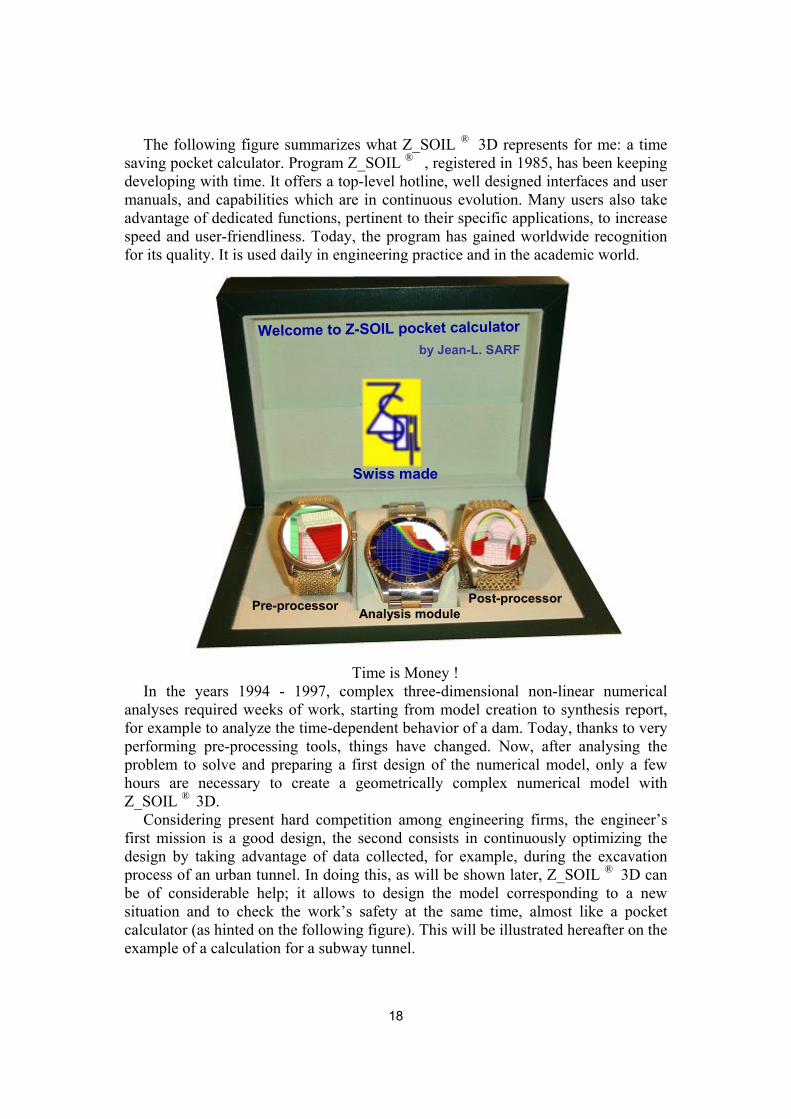
Considering present hard competition among engineering firms, the engineer’s first mission is a good design, the second consists in continuously optimizing the design by taking advantage of data collected, for example, during the excavation process of an urban tunnel. In doing this, as will be shown later, Z_SOIL ® 3D can be of considerable help; it allows to design the model corresponding to a new situation and to check the work’s safety at the same time, almost like a pocket calculator (as hinted on the following figure). This will be illustrated hereafter on the example of a calculation for a subway tunnel.
18
In the following sections of this article, I will indicate the time dedicated to the
creation of models. Considering that this article is written for the celebration of Z_SOIL ®, on the occasion of its 20th anniversary, names of consulting companies and names of the different works will be omitted.
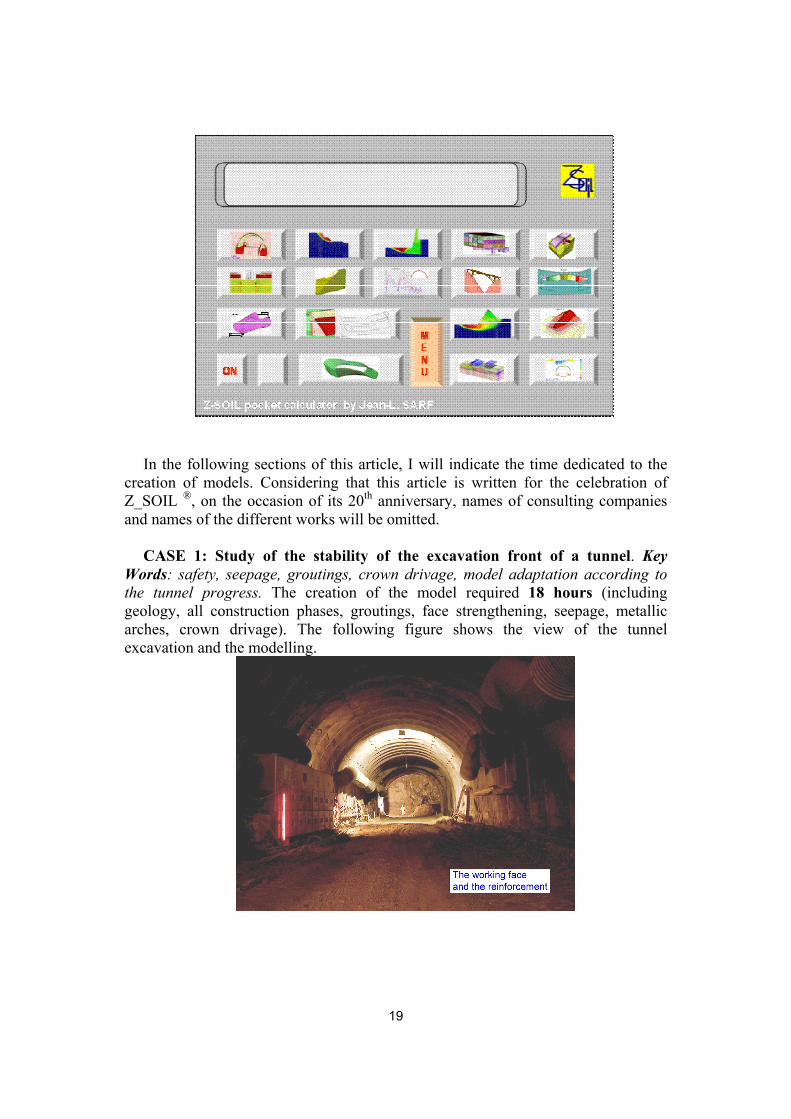
CASE 1: Study of the stability of the excavation front of a tunnel. Key
Words: safety, seepage, groutings, crown drivage, model adaptation according to the tunnel progress. The creation of the model required 18 hours (including geology, all construction phases, groutings, face strengthening, seepage, metallic arches, crown drivage). The following figure shows the view of the tunnel excavation and the modelling.
19

The following figure shows a zoom of the excavation front with the HEB 180 steel arch reinforcement and the modelling.
HEB 180 (s = 1m)
Protection vault 1
Excavation front reinforcement
Shotcrete
The following figure shows the definition of crown (protective umbrella)
20
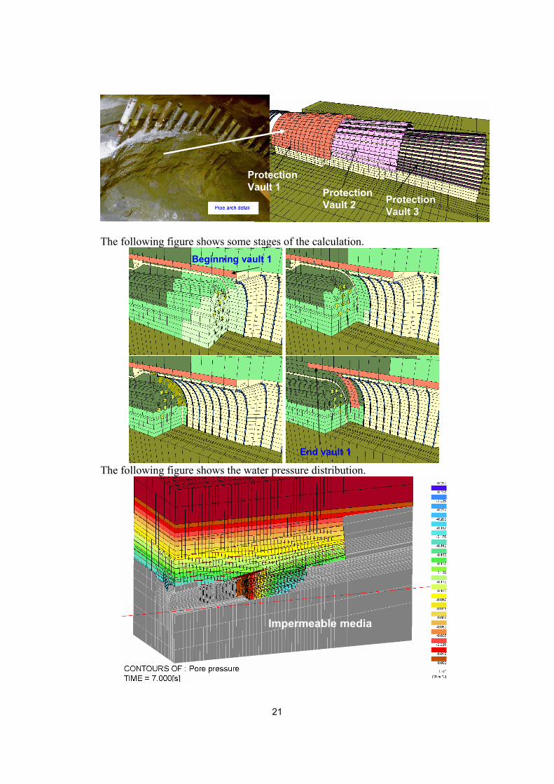
Protection Vault 2 Protection
Vault 3
Protection Vault 1
The following figure shows some stages of the calculation.
Beginning vault 1
End vault 1
The following figure shows the water pressure distribution.
Impermeable media
21
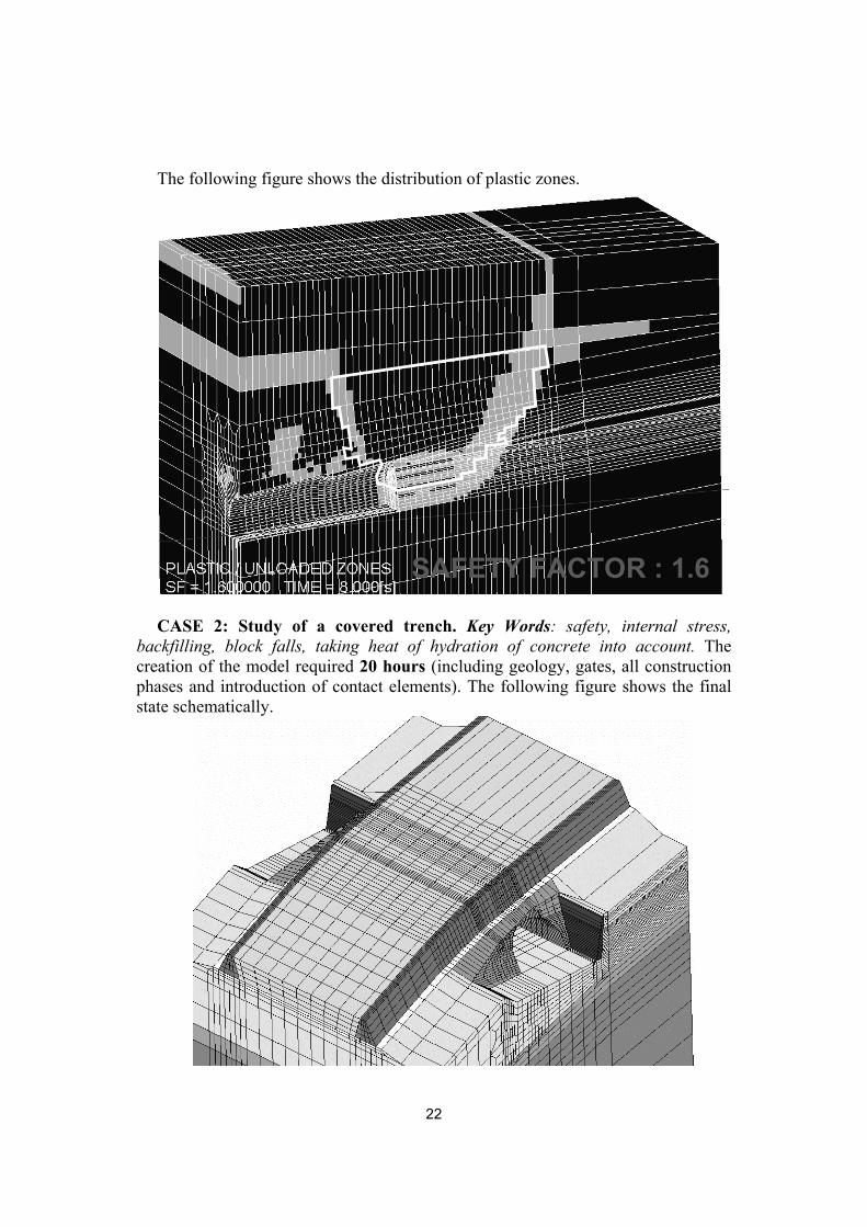
The following figure shows the distribution of plastic zones.
SAFETY FACTOR : 1.6
CASE 2: Study of a covered trench. Key Words: safety, internal stress,
backfilling, block falls, taking heat of hydration of concrete into account. The creation of the model required 20 hours (including geology, gates, all construction phases and introduction of contact elements). The following figure shows the final state schematically.
22
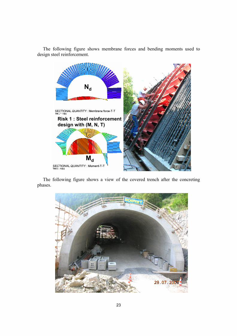
The following figure shows membrane forces and bending moments used to
design steel reinforcement.
Risk 1 : Steel reinforcement design with (M, N, T)
Nd
Md
The following figure shows a view of the covered trench after the concreting phases.
23

The following figure shows the studies of the concreting stages taking into
account the hydration of the concrete (transient computation). Two cases were studied: deshuttering after 3 or 7 days.
vault 1vault 2
Advance direction
for the concreting
vault 1
vault 2
10 20 30 40 50 60 70 80 90 100 110 120 130 140 150 160 170
TIME (h)
456789
101112131415161718192021222324252627282930313233343536
Tem
pér
ature
s (°
C)
Concreting vault 1(deshuttering cancel after 3 days)
Formwork cancel after 7 days
Temperature increase due to vault 2 concreting
Concreting vault 2(deshuttering cancel after 3 days)
CASE 3: Thermal Analysis of a RCC Gravity Dam during construction (CIGB ICOLD Benchmark). Key Words: considering the heat of hydration of the concrete, cofferdams, convective boundary conditions, transient calculation (time dependent) taking into account the program of concreting. This study was carried out in 60 hours (model, introducing all the stages of concreting, calculations, issue of results, synthesis report). The following figures show the main data and some results.
24
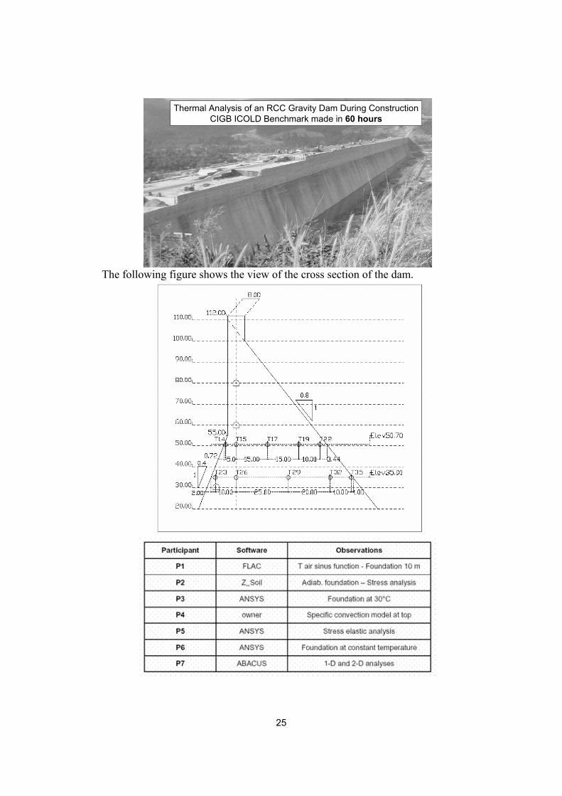
Thermal Analysis of an RCC Gravity Dam During ConstructionCIGB ICOLD Benchmark made in 60 hours
The following figure shows the view of the cross section of the dam.
25
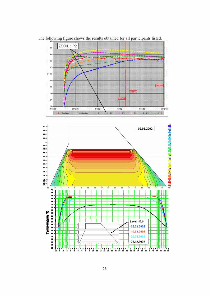
The following figure shows the results obtained for all participants listed.
-20 -15 -10 -5 0 5 10 15 20 25 30 35 40 45 50 55 60 65 70
21.122.322.323.523.524.724.725.325.3
28.628.6
31.631.6
34.934.9
37.937.9
40.940.9
43.943.9
46.946.9
49.949.950.6
52.952.9
5555
58.658.6
61.961.9
64.964.9
67.9
02.03.2002
26
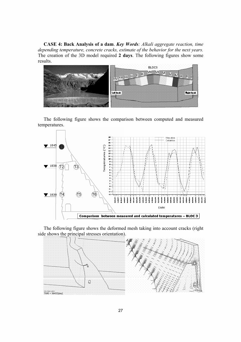
CASE 4: Back Analysis of a dam. Key Words: Alkali aggregate reaction, time depending temperature, concrete cracks, estimate of the behavior for the next years. The creation of the 3D model required 2 days. The following figures show some results.
The following figure shows the comparison between computed and measured
temperatures.
The following figure shows the deformed mesh taking into account cracks (right side shows the principal stresses orientation).
27

CASE 5: Back Analysis and elevation of an existing dam. Key Words: considering the heat of hydration of concrete, temperatures, effects of exposure to sun, cofferdams, contact elements between the new and the old dam. The creation of the 3D model for the elevation required 3 days (including introduction of calculation stages, cofferdam elements and contacts.
The following figure shows some stages of the calculation.
The following figure shows the temperature distribution in the central section
28

CASE 6: Study of a banded pipelines. Key Words: recreating the initial stress state, study of support settlement, considering expansion joints, considering contact elements and establishing of stress in the pipe. The following figures show some elements of this study.
The following figure shows some details of the case study.
6 m6 m
element 5521element 1441
element 1897
Principal stresses
Contact elements between lining and bands
29

The following figure shows initial stress (MPa) according to original design (1932).
1
2 3
4
5
6
7
8
Gauss points
Elément 552
1
Elément 144
1
Elément 1897
Principal stresses
(perspective view)
Compressions
tension
ELE GP S11 S22 S331441 1 -2.6 -9.9 -83.11441 2 8.6 -6.1 -82.71441 3 8.7 -5.0 -80.21441 4 -1.9 -9.3 -80.61441 5 -2.6 -9.9 -83.11441 6 8.6 -6.1 -82.71441 7 8.7 -5.0 -80.21441 8 -1.9 -9.3 -80.6
ELE GP S11 S22 S331897 1 15.16 0.34 -69.401897 2 0.70 -15.83 -82.701897 3 -0.17 -15.78 -82.421897 4 15.16 -0.56 -69.211897 5 15.16 0.34 -69.401897 6 0.70 -15.82 -82.701897 7 -0.17 -15.78 -82.421897 8 15.16 -0.56 -69.21
ELE GP S11 S22 S335521 1 78.26 -0.06 -4.455521 2 85.63 0.22 -4.455521 3 85.52 0.22 -4.465521 4 78.16 -0.06 -4.465521 5 78.26 -0.06 -4.455521 6 85.63 0.22 -4.455521 7 85.52 0.22 -4.465521 8 78.16 -0.06 -4.46
The following figure shows the old support and the modelling of the new one. New design
30
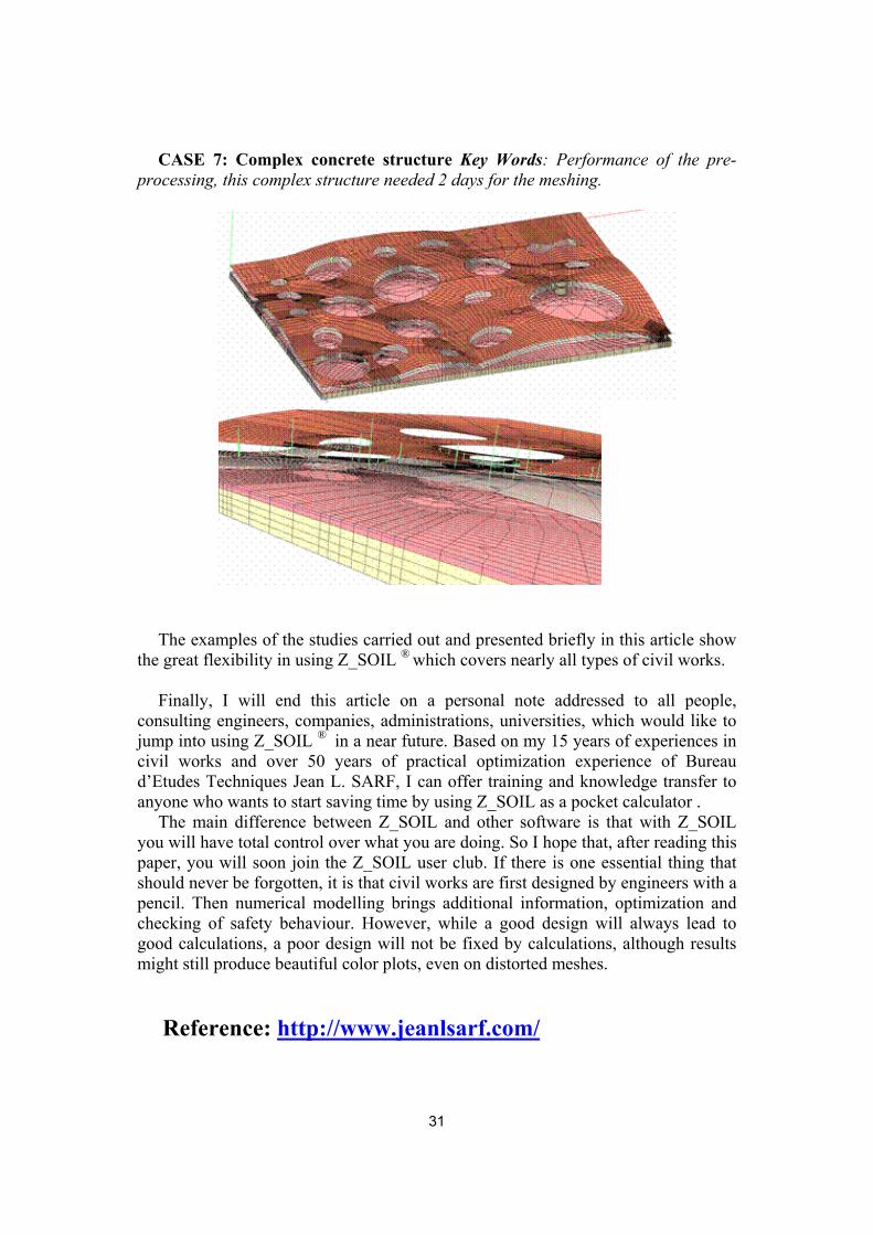
CASE 7: Complex concrete structure Key Words: Performance of the pre-processing, this complex structure needed 2 days for the meshing.
The examples of the studies carried out and presented briefly in this article show
the great flexibility in using Z_SOIL ® which covers nearly all types of civil works.
Finally, I will end this article on a personal note addressed to all people, consulting engineers, companies, administrations, universities, which would like to jump into using Z_SOIL ® in a near future. Based on my 15 years of experiences in civil works and over 50 years of practical optimization experience of Bureau d’Etudes Techniques Jean L. SARF, I can offer training and knowledge transfer to anyone who wants to start saving time by using Z_SOIL as a pocket calculator .
The main difference between Z_SOIL and other software is that with Z_SOIL you will have total control over what you are doing. So I hope that, after reading this paper, you will soon join the Z_SOIL user club. If there is one essential thing that should never be forgotten, it is that civil works are first designed by engineers with a pencil. Then numerical modelling brings additional information, optimization and checking of safety behaviour. However, while a good design will always lead to good calculations, a poor design will not be fixed by calculations, although results might still produce beautiful color plots, even on distorted meshes.
Reference: http://www.jeanlsarf.com/
31

32