zander filter systems, inc. 5201-d brook hollow pkwy
TRANSCRIPT
Zander Filter Systems, Inc.5201-D Brook Hollow Pkwy.
Norcross, GA. 30071
(770)446-3614 * Fax (770)263-0856
Toll Free 1-800-543-0851
ZAHDER@
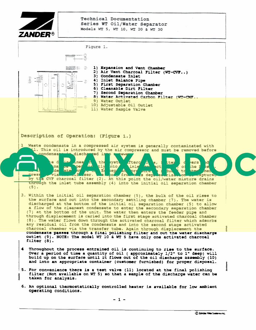
1) Expan8ion and Vent Chamber2) Air Vent Charcoal Filter (WT-CVP..)3) Conden8ate Inlet4) Inlet Balance Pipe5) First Separation Chamber6) Cleanable Dirt Filter7) Second Separation Chamber8) Water Activated Carbon Filter (WT-CMF..9) Water OUtlet
10) Adju8table Oil OUtlet11) Water Sample Valve
Description of operation: (Fiqure1..)
1 Waste condensate in a compressed air system is generally contaminated withoil. This oil i. introduced by the air compressor and must be removed beforethe conden8ate i8 di8charqed into a sewer.
2 Condensate drain lines from the system aftercoolers, filters, dryers andreceivers may be piped directly into the inlet connection (3) of the Ecosep.As the condensate enters the Ecosep, any pressure i8 reduced to atmosphericpressure via the diffuser. The spray from this depressurization is capturedby the CVF charcoal filter (2). At this point the oil/water mixture drainsthrough the inlet tube as8embly (4) into the initial oil separation chamber(5) .
3. Within the initial oil separation chamber (5), the bulk of the oil rises tothe surface and out into the .8condary settlinq chamber (7). The water isdischarqed at the bottom of the initial oil separation chamber (5) to allowa flow of the cleanest conden.ate to enter the secondary separation chamber
(7) at the bottom of the unit. The water then enter. the feeder pipe andthrouqh displacement is caried into the first staqe activated charcoal chamber(8). The water flows down throuqh the activated charcoal filter which adsorb.any re.idual oil from the condensate and into the second staqe activatedcharcoal chamber via the transfer tube. Aqain throuqh displacement thecondensate passe. throuqh a final polishinq filter and out the water dischargeoutlet (9). NOTE: The model WT 10 & WT 5 have only one activated charcoalfilter (8).
4 Throughout the process entrained oil is continuing to ri8e to the surface.Over a period of time a quantity of oil ( approximately 1/2" to 1" deep) willbuild up on the surface until it flow8 out of the oil di8charge assembly (10)and into an appropriate container (customer furnished) for proper disposal.
5. For convenience there is a test valve (11) located at the final polishingf il ter (Not available on WT 5) so that a sample of the discharge water can betaken for analysis.
6. An optional thermostatically controlled heater is available for low ambient
operating conditions.
- 1 -
-~Zawa~~~

Installation of the Ecosep:
Install the Ecosep in a frost free environment
Ensure the Ecosep is ins~alled in a stationary surface and ~ha~ the unit iscompletely level. If after ins~allation the Ecosep is bumped, shaken,subjected to vibration or not level, effective separation of ~he oil and wateris significan~ly reduced.
3 Thoroughly wash the charcoal filters with clean water to remove ~he finecharcoal dust. Then ins~all the filters in the appropriate chambers.
4 Fill the Ecosep with clean water until it begins to flow out of the waterdischarge (9). 8e sure oil adjustment is as high as possible before fillingthe unit.
5 Ensure that ~he initial oil separation chamber (5) is fi~y seated to thebottom of the unit and that the inlet tube assembly (4) is snapped into placeat the top of chamber (5).
6 Adjust the sleeve of the oil discharge assembly (10) so that the top of thesleeve is approximately 3/4" above the waterline. It will take some time afterplacing the unit in operation before a layer of oil builds up on the surfaceand begins to drain out of the separator. If during operation water isdraining out of the oil discharge, raise the sleeve approximately an .ddtiona~1/4".
. Connect the systeM condensate line of the separator utilizing flexible tubing
or hose. Do Not Ina~l ~ Separator Using ~gid Pipe.
8 Connect both the water and oil discharge lines. The use of clear tubing issuggested for visual inspection purposes. The oil discharge line should draininto a suitable container for disposal in accordance with local regulations.
Non For optimum performance we recommend the use of Zander's Ecodrain, a f~lyautomatic self-regula~ing condensate drain.
-.C:~..~~
ZAHDER@
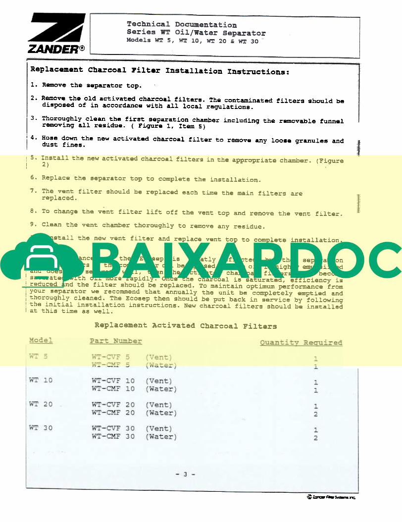
Replacement Charcoal Filter Installation Instructions:
1. Remove the separator top.
2. Remove the old activated charcoal filters. The contaminated filters should be
disposed of in accordance with all local regulations.
3. Thoroughly clean the first separation chamber including the removable funnel
removing all residue. ( Fiqure 1, Item 5)
4. Hose down the new activated charcoal filter to remove any loose granules and
dust fines.
i 5. Install the new activated charcoal filters in the appropriate chamber. (Figure
I 2)
6. Replace the separator top to complete the installation.
7 . The vent filter should be replaced each time the main filters are
replaced.
8. To change the vent filter lift off the vent top and remove the vent filter.
9. Clean the vent chamber thorouqhly to remove any residue.
10. Install the new vent filter and replace vent top to complete installation.
: The performance of the Ecosep is greatly effected by the separation
; characteristics of the compressor oil being used. If the oil is highly emulsified: and does not separate well, then the activated- charcoal f.ilters will becomeI saturated with o.il more rapidly. Once the charcoal is saturated, eff.ic.iency is
reduced and the f il ter should be replaced. To mainta.in opt.imum performance from
your separator we reccmmend that annually the un.it be completely emptied andthoroughly cleaned. The Ecosep then should be put back .in service by following
. the init.ial installation .instructions. New charcoal filters should be installed
I at this time as well.
Replacement Activated Charcoal Filters
~~~s-..~
Technical Docuaentationseries WT oil/Water separatorModels wr 5, wr 10, wr 20 & wr 30
ZAHDER@
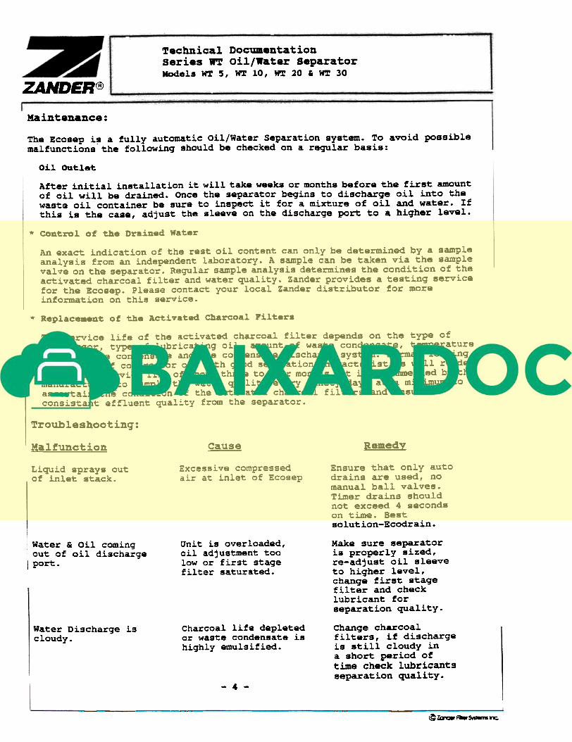
Maintenance:
The Ecosep i~ a fully automatic Oil/Water Separation system. To avoid possiblemalfunctions the following should be checked on a regular basis:
oil. Ou't.l.e't.
After inLtial installation it will take weeks or months before the first amountof oil will be drained. Once the separator begins to discharge oil into thewaste oil container be sure to inspect it for a mixture of oil and water. Ifthis is the case, adjust the sleeve on the discharge port to a higher level.
'* Con~roJ. of the Drained Wa~.r
An exact indication of the rest oil content can only be determined by a sampleanalysis from an independent laboratory. A sample can be taken via the samplevalve on the separator. Regular sample analysis determines the condition of the
activated charcoal filter and water quality. Zander provides a testing servicefor the Ecosep. Please contact your local Zander distributor for more
information on this service.
* Replac...n~ of the Activa~ed Charcoal Pil~ers
The service life of the activated charcoal filter depends on the type of
compressor, type of lubricating oil, amount of waste condensate, temperatureof the waste condensate and the condensate discharge system. Normal loadingconditions of compressor oil with good separation characteristics will renderan average service life of about three to four months. It is recommended by themanufacturer to sample the water quality every ninety days at a minimum toascertain the condition of the activated charcoal filters and ensure a
consistant effluent quality from the separator.
Troubleshootinq:
RemedYMalfunction gause
Excessive compressedair at inlet of Ecosep
Ensure that only autodrains are used, nomanual ball valves.Timer drains shouldnot exceed 4 secondson time. Bestsolution-Ecodrain.
Liquid sprays outof inlet stack.
Unit is overloaded,oil adjustment toolow or first stagefilter saturated.
Water & Oil comingout of oil discharge
I port.
Make sure separatoris properly sized,re-adjust oil sleeve
to higher level,change first stagefilter and checklubricant for
separation quality.
Charcoal life depletedor waste condensate ishighly emulsified.
Water Discharge is
cloudy.
change charcoalfilters, if dischargeis still cloudy ina short period of
time check lubricants
separation quality.- 4 -
~law:.~~~
ZAHDER@
s
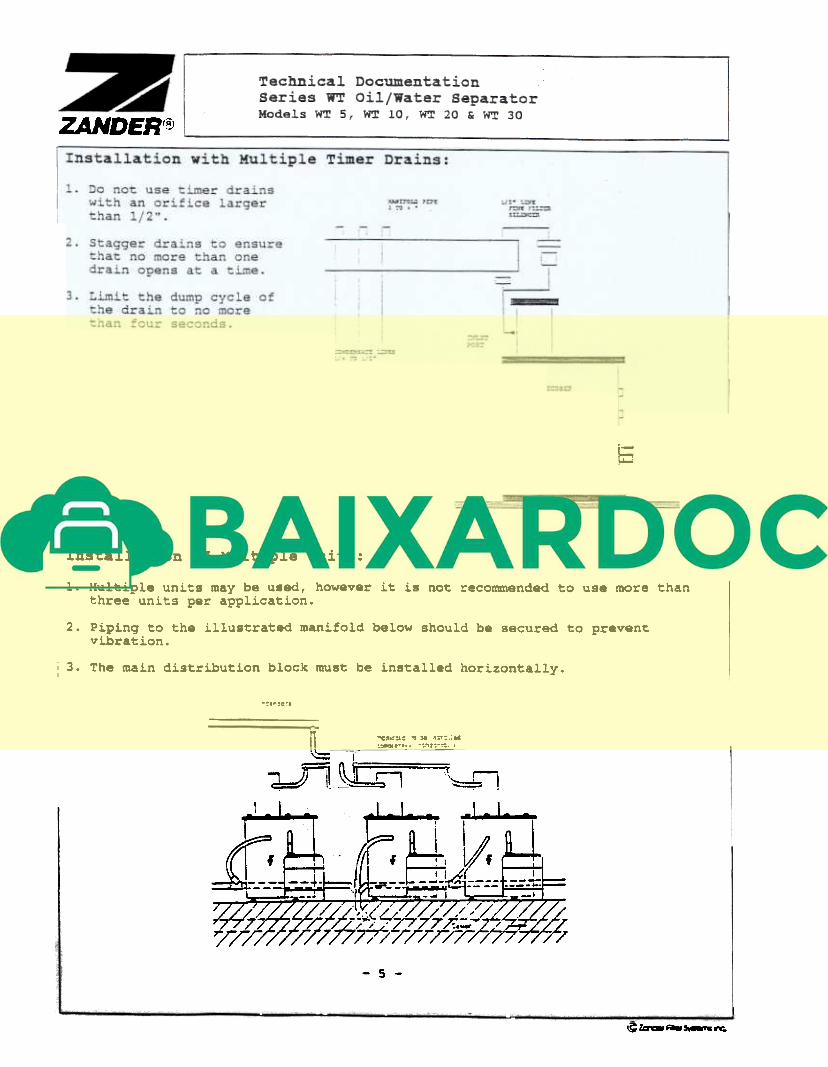
Installation of Multiple units:
1. Multiple units may be u8ed, however it is not recommended to use more thanthree units per application.
2. Piping to the illustrated manifold below should be secured to preventvibration.
: 3. The main distribution block must be installed horizontally.
"""'"
l -l
"J:=~:1 ~~ ~
o-e..l:IC ,,)0 ":::.;OC:-.-,.. .~""~.
~=*I
~
- 5 -
\Cla18~~~
ZA..NDER(~
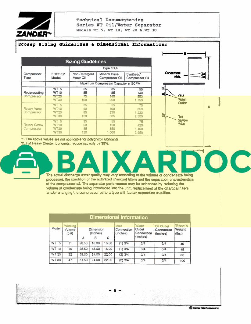
Ecosep Sizinq Guidelines' Dimensional Intor.ation:
1-. ~
CondensateInlets -- ~
:'~~CkJIIICs
A
~I ~IeI Vaiw
-,. The above values .. oot ~pllcabl8 for POIygI~11ubfican18
-2. For Heavy Diester lubricants. reduce capacity by 35".. -1I" of
The actual discharge water quality may vary ~rding to the volume of ~ndensat8 beingprocessed. the ~ndition of the activated char=aI filters and the separation charaderisticsof the ~mpressor oil. The separator performance may be enhanced by reducing thevolume of ~ndensate being introduced into the unit. replacement of the char=aI filtersand/or ~anging the compressor oil to a type with better separation qualities.
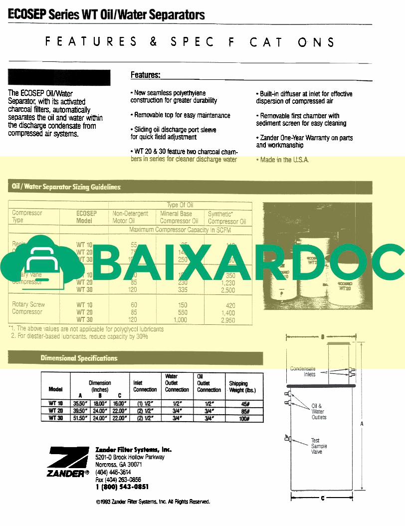
F EAT U RES & 5 P E C F CAT 0 N S
Features:
. New seamless polyethylene
construction for greater durability
. Built-in diffuser at inlet for effective
dispersion of compressed airThe ECOSEP Oil/Water
Separato~ with its activatedcharcoal filters, automatically
separates the oil and water withinthe discharge condensate from
compressed air systems.
. Removable top for easy maintenance . Removable first chamber with
sediment screen for easy cleaning. Sliding oil discharge port sleeve
for quick field adjustment . Zander One-Year Warranty on parts
and workmanship. WT 20 & 30 feature two charcoal cham-
bers in series for cleaner discharge water . Made in the U.S.A.
,- 'I '1
Water
Outlet
Connection
OilOutletConnection
Dimension
(Inches)B
Shipping
~ght (Ibs.)Model
InletConnection
A cI 35:50~I~I_l&:OO-'WT10 .t1L1;g,:
rf1J!1::.(2) 1fl-
~3/4'
3/4'-
1~-
3/4-
3/4-
45#
85#
100#
WI 20 I 39,50' I 24.00' I 22.00' I
WT 30 I 51.50~r~l~
~::- laBder Filter Systems, 1-.~ 5201-0 Brook HolIC1N Parkway~ Norcross. GA 30071
ZANDER~ (404) 446-3614
Fax (404) 263-0856
1 (800) 543-0851
I=~ c.- -4@1993 Zander Filter S~ Inc. AI ~hts ReseMd.
ZAHDER@
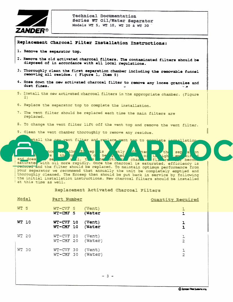
Replacement Charcoal Filter Installation Instructions:
1. Remove the separator ~op.
2. Remove the old activated charcoa.l fi.lters. The contaminated fi.lters shou.ld bedisposed of in accordance with a.l.lloca.l regulations.
3. Thoroughly clean the first separation chamber including the removable funnel
removin~all resiaue. ( Figure 1, Item 5)
4. Hose down the new activated charcoal filter to remove any loose granules ana
aust fines. ., -.
5. Install the new activated charcoal filters in the appropriate chamber. (Figure
2)
6. Replace the separator top to complete the installation.
7. The vent filter should be replaced each time the main filters are
replaced.
8. To change the vent filter lift off the vent top and remove the vent filter.
9. Clean the vent chamber thorouqhly to remove any residue.
10. Install the new vent filter and replace vent top to complete installation.
: The performance of the Ecosep is greatly effected by the separation: characteristics of the compressor oil being used. If the oil is highly emulsified'and does not separate well, then the activated charcoal filters will becomei saturated with oil more rapidly. Once the charcoal is saturated, efficiency is
reduced and the f il ter should be replaced. To maintain optimum performance fromyour separator we reccmmend that annually the unit be completely emptied andthoroughly cleaned. The Ecosep then should be put back in service by followL~g
. the initial installation instructions. New charcoal filters should be installed! at this time as well.
Replacement Activated Charcoal Filters
Model Part Number Quanti t~ Reauired
WT5 WT -CVF 5
WT-CMF 5(Vent)(Water
11
WT 10 WT-CVF 10WT-CMF 10
(Vent)(Water
1.
1.
@~~=-rs~