zenit z180 g2
TRANSCRIPT
USER´S MANUALBEDIENUNGSANLEITUNG MANUEL D´UTILISATIONMANUAL DE USUARIOINSTRUKCJA OBSŁUGIMANUALE D´USO
ZENIT® Z180 G2 OUTDOOR ZENIT ZOOM 180 G2 CLZZ180G2
CONTENTS / INHALTSVERZEICHNIS / CONTENU / CONTENIDO / TREŚĆ / CONTENUTO
ENGLISHPREVENTIVE MEASURES 3-4INTRODUCTION 4 CONNECTIONS, OPERATING AND DISPLAY ELEMENTS 5-6OPERATION 6-11INSTALLATION AND MOUNTING 12DMX TECHNOLOGY 13TECHNICAL DATA 14MANUFACTURER’S DECLARATIONS 15DMX CONTROL 81-86
DEUTSCHSICHERHEITSHINWEISE 16-17EINFÜHRUNG 17-18ANSCHLÜSSE, BEDIEN- UND ANZEIGEELEMENTE 18-19BEDIENUNG 19-25AUFSTELLUNG UND MONTAGE 25DMX TECHNIK 26TECHNISCHE DATEN 27HERSTELLERERKLÄRUNGEN 28DMX STEUERUNG 81-86
FRANCAISMESURES PRÉVENTIVES 29-30INTRODUCTION 30RACCORDEMENTS, ÉLÉMENTS DE COMMANDE ET D’AFFICHAGE 31-32UTILISATION 32-38INSTALLATION ET MONTAGE 38TECHNOLOGIE DMX 39CARACTÉRISTIQUES TECHNIQUES 40DÉCLARATIONS DU FABRICANT 41PILOTAGE EN MODE DMX 81-86
ESPAÑOLMEDIDAS DE SEGURIDAD 42INTRODUCCIÓN 43CONEXIONES, ELEMENTOS DE MANEJO Y ELEMENTOS DE VISUALIZACIÓN 44-45MANEJO 45-50INSTALACIÓN Y MONTAJE 51TECNOLOGÍA DMX 52DATOS TÉCNICOS 53DECLARACIONES DEL FABRICANTE 54CONTROL DMX 81-86
POLSKIŚRODKI OSTROŻNOŚCI 55-56WPROWADZENIE 56-57GNIAZDA, ELEMENTY OBSŁUGI I WSKAŹNIKI 57-58OBSŁUGA 58-63USTAWIANIE I MONTAŻ 64TECHNIKA DMX 65DANE TECHNICZNE 66OŚWIADCZENIA PRODUCENTA 67STEROWANIE DMX 81-86
ITALIANOMISURE PRECAUZIONALI 68-69INTRODUZIONE 69CONNESSIONI, ELEMENTI DI COMANDO E VISUALIZZAZIONE 70-71UTILIZZO 71-76INSTALLAZIONE E MONTAGGIO 77TECNOLOGIA DMX 78DATI TECNICI 79DICHIARAZIONI DEL PRODUTTORE 80CONTROLLO DMX 81-86
3
DMX
DEUTSC
HFRAN
CAIS
ESPAÑO
LEN
GLISH
ITALIANO
POLSKI
ENGLISH
YOU‘VE MADE THE RIGHT CHOICE!We have designed this product to operate reliably over many years. Please read this User‘s Manual carefully, so that you can begin making optimum use of your Cameo Light product quickly. Learn more about Cameo Light on our website WWW.CAMEOLIGHT.COM.
PREVENTIVE MEASURES1. Please read these instructions carefully. 2. Keep all information and instructions in a safe place. 3. Follow the instructions. 4. Observe all safety warnings. Never remove safety warnings or other information from the equipment. 5. Use the equipment only in the intended manner and for the intended purpose. 6. Use only sufficiently stable and compatible stands and/or mounts (for fixed installations). Make certain that wall mounts are properly installed and secured. Make certain that the equipment is installed securely and cannot fall down. 7. During installation, observ e the applicable safety regulations for your country. 8. Never install and operate the equipment near radiators, heat registers, ovens or other sources of heat. Make certain that the equipment is always installed so that is cooled sufficiently and cannot overheat. 9. Never place sources of ignition, e.g., burning candles, on the equipment. 10. Ventilation slits must not be blocked. 11. This appliance is designed exclusively for indoor use, do not use this equipment in the immediate vicinity of water (does not apply to special outdoor equipment - in this case, observe the special instructions noted below). Do not expose this equipment to flammable materials, fluids or gases. 12. Make certain that dripping or splashed water cannot enter the equipment. Do not place containers filled with liquids, such as vases or drinking vessels, on the equipment. 13. Make certain that objects cannot fall into the device. 14. Use this equipment only with the accessories recommended and intended by the manufacturer. 15. Do not open or modify this equipment. 16. After connecting the equipment, check all cables in order to prevent damage or accidents, e.g., due to tripping hazards. 17. During transport, make certain that the equipment cannot fall down and possibly cause property damage and personal injuries.18. If your equipment is no longer functioning properly, if fluids or objects have gotten inside the equipment or if it has been damaged in anot her way, switch it off immediately and unplug it from the mains outlet (if it is a powered device). This equipment may only be repaired by authorized, qualified personnel. 19. Clean the equipment using a dry cloth. 20. Comply with all applicable disposal laws in your country. During disposal of packaging, please separate plastic and paper/cardboard. 21. Plastic bags must be kept out of reach of children.
FOR EQUIPMENT THAT CONNECTS TO THE POWER MAINS:22. CAUTION: If the power cord of the device is equipped with an earthing contact, then it must be connected to an outlet with a protective ground. Never deactivate the protective ground of a power cord. 23. If the equipment has been exposed to strong fluctuations in temperature (for example, after transport), do not switch it on immediately. Moisture and condensation could damage the equipment. Do not switch on the equipment until it has reached room temperature. 24. Before connecting the equipment to the power outlet, first verify that the mains voltage and frequency match the values specified on the equipment. If the equipment has a voltage selection switch, connect the equipment to the power outlet only if the equipment values and the mains power values match. If the included power cord or power adapter does not fit in your wall outlet, contact your electrician. 25. Do not step on the power cord. Make certain that the power cable does not become kinked, especially at the mains outlet and/or power adapter and the equipment connector. 26. When connecting the equipment, make certain that the power cord or power adapter is always freely accessible. Always disconnect the equipment from the power supply if the equipment is not in use or if you want to clean the equipment. Always unplug the power cord and power adapter from the power outlet at the plug or adapter and not by pulling on the cord. Never touch the power cord and power adapter with wet hands. 27. Whenever possible, avoid switching the equipment on and off in quick succession because otherwise this can shorten the useful life of the equipment.28. IMPORTANT INFORMATION: Replace fuses only with fuses of the same type and rating. If a fuse blows repeatedly, please contact an authorised service centre. 29. To disconnect the equipment from the power mains completely, unplug the power cord or power adapter from the power outlet. 30. If your device is equipped with a Volex power connector, the mating Volex equipment connector must be unlocked before it can be re-moved. However, this also means that the equipment can slide and fall down if the power cable is pulled, which can lead to personal injuries and/or other damage. For this reason, always be careful when laying cables. 31. Unplug the power cord and power adapter from the power outlet if there is a risk of a lightning strike or before extended periods of disuse.32. The device must only be installed in a voltage-free condition (disconnect the mains plug from the mains).33. Dust and other debris inside the unit may cause damage. The unit should be regularly serviced or cleaned (no guarantee) depending on ambient conditions (dust etc., nicotine, fog) by qualified personnel to prevent overheating and malfunction.34. Please keep a distance of at least 0.5 m to any combustible materials.35. Power cables to power multiple devices must have a cross-section of at least 1.5 mm². Within the EU, the cables must correspond to H05VV-F, or similar. Suitable cables are offered by Adam Hall. With these cables, you can connect multiple devices via the power OUT connection to the power IN connection of an additional device. Make sure that the total current consumption of all connected devices does not exceed the specified value on all connected devices (label on the device). Make sure to keep power cable connections as short as possible.

4
DMX
ITALIANOPOLSKI
ESPAÑOLFRANCAIS
DEUTSCHENGLISH
CAUTION:To reduce the risk of electric shock, do not remove cover (or back). There are no user serviceable parts inside. Maintenance and repairs should be exclusively carried out by qualified service personnel.
The warning triangle with lightning symbol indicates dangerous uninsulated voltage inside the unit, which may cause an electrical shock.
The warning triangle with exclamation mark indicates important operating and maintenance instructions.
Warning! This symbol indicates a hot surface. Certain parts of the housing can become hot during operation. After use, wait for a cool-down period of at least 10 minutes before handling or transporting the device.
Warning! This device is designed for use below 2000 metres in altitude.
Warning! This product is not intended for use in tropical climates.
Caution! Intense LED light source! Risk of eye damage. Do not look into the light source.
CAUTION! IMPORTANT INFORMATION ABOUT LIGHTING PRODUCTS!1. The product has been developed for professional use in the field of event technology and is not suitable as household lighting.2. Do not stare, even temporarily, directly into the light beam.3. Do not look at the beam directly with optical instruments such as magnifiers.4. Stroboscope effects may cause epileptic seizures in sensitive people! People with epilepsy should definitely avoid places wherestrobes are used.
INTRODUCTIONOUTDOOR ZENIT ZOOM 180 G2
CLZZ180G2
CONTROL FUNCTIONS
3-channel, 4-channel, 5-channel, 9-channel, 10-channel, 11-channel, and 17-channel DMX controller
Master / slave mode
Standalone functions
PROPERTIES
Outdoor spotlight with zoom function and a 180W COB-LED (RGBW). 7 DMX modes. DMX-512 control. Master / slave mode. Standalone functions. Stand and/or mounting bracket and 16mm TV spigot included. Operating voltage: 100V - 240V AC / 50 - 60Hz. Power consump-tion: 220W. IP65 protection.

5
DMX
DEUTSC
HFRAN
CAIS
ESPAÑO
LEN
GLISH
ITALIANO
POLSKI
5
1 2 3 44
7
8
6
The spotlights comply with the RDM standard (Remote Device Management). This device manager allows the user to request the status of and configure RDM end devices via an RDM-capable controller.
CONNECTIONS, CONTROL AND DISPLAY ELEMENTS
1 POWER IN
IP65 Power Twist power input connector with rubber sealing cap. Operating voltage: 100 - 240V AC / 50 - 60Hz. Connect using the provided power cable (when not in use, always close with rubber sealing cap).
2 POWER OUT
IP65 Power Twist power output connector with rubber sealing cap. Serves to provide power to additional CAMEO spotlights. Ensure that the total power consumption of all devices connected to the device does not exceeded the given Ampere (A) value (when not in use, always close with rubber sealing cap).
3 DMX IN
Male IP65 5-pin XLR connector to connect a DMX controller (e.g. DMX console, when not in use, always close with rubber sealing cap).
4 DMX OUT
Female IP65 5-pin XLR connector to transmit a DMX controller signal (when not in use, always close with rubber sealing cap).
5 OLED DISPLAY
Displays the current operating mode and other system settings.

6
DMX
ITALIANOPOLSKI
ESPAÑOLFRANCAIS
DEUTSCHENGLISH
6 TOUCH-SENSITIVE CONTROL FIELDS WITH BACKLIGHTING
MODE
Access the selection menu for system settings by pressing MODE. Pressing it again will return you to the main menu.
ENTER
Pressing ENTER will take you to the menu level in order to apply value changes and to reach one of the submenus. You can also confirm value adjustments by pressing ENTER.
UP and DOWN
Selects the individual menu options in the selection menu (DMX address, operating mode, etc.) and in the submenus. Allow you to change the value of a menu option, such as the DMX address, as desired.
7 PRESSURE EQUALIZATION ELEMENT
Pressure equalization element to avoid the buildup of condensation within the housing. Protect this element from contamination in order to ensure that it functions properly.
8 SAFETY EYEBOLT
When installing in an overhead location, secure the device using a suitable safety cable on the safety eyebolt.
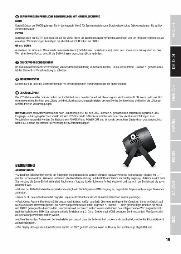
9 HOUSING FAN
The IP65 housing fan is located in the cooling unit between the controller unit and the unit with LED, zoom, and lens. Do not cover the machine and keep the ventilation slats free of contaminants in order to ensure that the fan functions properly and that air can circulate freely.
NOTE: In order to ensure that the DMX sockets are protected from spray water in accordance with the IP65 protection class, the special DMX input and output sockets must be correctly sealed with the special IP65 XLR plug or capped with the rubber sealing cap. When connected correctly, the POWER IN and POWER OUT sockets will protect against spray water in accordance with IP65, as will the rubber sealing cap.
9
OPERATIONNOTES
• As soon as the spotlight is correctly connected to the power mains, “Update Wait...” (only for servicing purposes), “Welcome to Cameo”, the model designation, and then the software version are displayed in sequence on the display as part of the startup process. The zoom unit will also initialize during startup. Once the process is complete, the spotlight is ready for use and resumes whichever mode was most recently set.
• If one of the DMX modes is active, and there is no DMX signal at the DMX input, the display will begin to blink after a few seconds.
• After approx. 30 seconds of inactivity, the display will automatically show the currently active operating mode (main display).
• Fast Access feature: In order to make navigating the menu simpler, the device has an intelligent menu structure that makes it possible to directly access menu and submenu options that were previously selected. 1. Pressing MODE and ENTER at the same time will take you directly to the submenu option that was last modified, where you can immediately change the value as desired (DMX start address and all operating modes). 2. Pressing MODE will take you directly to the menu option that was last selected and modified.
• Before changing device settings, make sure that the control unit is dry and dust-free in order to ensure that it is functioning properly.
• The display can be rotated by 180° by pressing UP when the main screen is shown on the display.
7
DMX
DEUTSC
HFRAN
CAIS
ESPAÑO
LEN
GLISH
ITALIANO
POLSKI
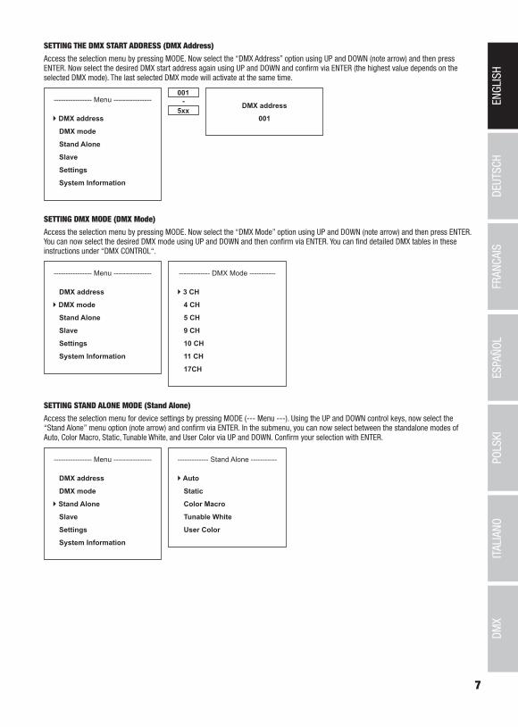
SETTING THE DMX START ADDRESS (DMX Address)
Access the selection menu by pressing MODE. Now select the “DMX Address” option using UP and DOWN (note arrow) and then press ENTER. Now select the desired DMX start address again using UP and DOWN and confirm via ENTER (the highest value depends on the selected DMX mode). The last selected DMX mode will activate at the same time.
---------------- Menu ----------------
DMX address
DMX mode
Stand Alone
Slave
Settings
System Information
001
5xx- DMX address
001
SETTING DMX MODE (DMX Mode)
Access the selection menu by pressing MODE. Now select the “DMX Mode” option using UP and DOWN (note arrow) and then press ENTER. You can now select the desired DMX mode using UP and DOWN and then confirm via ENTER. You can find detailed DMX tables in these instructions under “DMX CONTROL“.
---------------- Menu ----------------
DMX address
DMX mode
Stand Alone
Slave
Settings
System Information
------------- DMX Mode -----------
3 CH
4 CH
5 CH
9 CH
10 CH
11 CH
17CH
SETTING STAND ALONE MODE (Stand Alone)
Access the selection menu for device settings by pressing MODE (--- Menu ---). Using the UP and DOWN control keys, now select the “Stand Alone” menu option (note arrow) and confirm via ENTER. In the submenu, you can now select between the standalone modes of Auto, Color Macro, Static, Tunable White, and User Color via UP and DOWN. Confirm your selection with ENTER.
---------------- Menu ----------------
DMX address
DMX mode
Stand Alone
Slave
Settings
System Information
------------- Stand Alone -----------
Auto
Static
Color Macro
Tunable White
User Color

8
DMX
ITALIANOPOLSKI
ESPAÑOLFRANCAIS
DEUTSCHENGLISH
STAND ALONE MODE AUTO (Auto Program 1- 6)
The 6 different Auto programs consist of pre-programmed color change sequences; brightness and speed are configured separately. Now select Auto mode and confirm by pressing ENTER, as described under "SETTING STAND ALONE MODE”. Now select one of the 6 Auto programs using the UP and DOWN keys (note arrow) and confirm via ENTER. Now, to set the brightness, select the “Dimmer” menu option using UP and DOWN, confirm via ENTER, and select the desired value from 000 to 100 using the UP and DOWN keys. Confirm via ENTER. Now, to set the speed, select the "Speed” menu option, confirm via ENTER, and set the desired value from 000 to 100. The value for the zoom function is set in the same manner. Confirm all value changes via ENTER.
Mode
Auto
-------- Stand Alone -------
Auto
Static
Color Macro
Tunable White
User Color
----------- Auto -----------
Program 1
Program 2
Program 3
Program 4
Program 5
Program 6
--------- Program x ---------
Dimmer <100>
Speed <100>
Zoom <100>
000
100-
Dimmer Speed
000
100-
STAND ALONE STATIC MODE (Static)
Static mode makes it possible, as with a DMX control device, to configure the dimmer, strobe, R, G, B, and W, etc., values from 000 to 255 directly on the device. This allows the user to create individual scenes without needing an additional DMX controller. Now select Static mode and confirm by pressing ENTER, as described under "SETTING STAND ALONE MODE”. Now select the menu option you would like to change using the UP and DOWN keys (note arrow) and confirm via ENTER. A three-digit number field will now appear on the display, and you can set the value as desired from 000 to 255 via the UP and DOWN keys. Confirm via ENTER. The values to configure the strobe function correspond to the values of the multifunctional strobe in the DMX tables.
Mode
Static
-------- Stand Alone -------
Auto
Static
Color Macro
Tunable White
User Color
----------- Static -----------
Dimmer <255>
DimFine <255>
Strobe <255>
Red <255>
Green <255>
Blue <255>
White <255>
Color Temp <255>
Zoom <255>
Zoom Fine <255>
000
255-
Zoom
000
100-

9
DMX
DEUTSC
HFRAN
CAIS
ESPAÑO
LEN
GLISH
ITALIANO
POLSKI
STAND ALONE MODE COLOR MACROS (Color Macro)
15 different color macros are available as presets. Now select the “Color Macro“ menu option and confirm by pressing ENTER, as described under "SETTING MODE”. Now select the desired color presets using the UP and DOWN keys (note arrow) and confirm via ENTER (Color Off = blackout). A three-digit number field will now appear on the display, and you can set the brightness as desired from 000 to 100 via the UP and DOWN keys. Confirm via ENTER. The zoom function is configured in the same manner.
Mode
Color Macro
------- Stand Alone ------
Auto
Static
Color Macro
Tunable White
User Color
----- Color Macro -----
Color Off
Red <100>
Amber <100>
Yellow Warm <100>
Yellow <100>
Green <100>
Turquoise <100>
Cyan <100>
000
100-
Blue <100>
Lavender <100>
Mauve <100>
Magenta <100>
Pink <100>
Warm White <100>
White <100>
Cold White <100>
Zoom <100>
STAND ALONE MODE COLOR TEMPERATURE (Tunable White)
Color Temperature mode makes it possible to configure the light with a color temperature of cold white to warm white (CTC), the brightness (Dimmer), and the zoom function directly on the device. Now select Color Temperature mode and confirm by pressing ENTER, as described under "SETTING STAND ALONE MODE”. Now select the menu option you would like to change using the UP and DOWN keys (note arrow) and confirm via ENTER. A three-digit number field will now appear on the display, and you can set the value as desired via the UP and DOWN keys. Confirm via ENTER.
Mode
Tunable White
------- Stand Alone ------
Auto
Static
Color Macro
Tunable White
User Color
----- Tunable White -----
Dimmer <100>
CTC <100>
Zoom <100>
000
100-
STAND ALONE MODE USER PRESETS (User Color)
The “User Presets” standalone mode makes it possible to save the overall brightness and a color mixture of R, G, B, and W, etc. to four individual color presets directly on the device. Now select the “User Color” option and confirm by pressing ENTER, as described under "SETTING STAND ALONE MODE”. Now select one of the presets, Color 1 to Color 4, using the UP and DOWN keys, confirm via ENTER, and select the submenu option that you would like to change (note arrow). Confirm via ENTER. A three-digit number field will now appear on the display, and you can set the value as desired from 000 to 255 via the UP and DOWN keys. Then confirm via ENTER. The values to configure the strobe function correspond to the values of the multifunctional strobe in the DMX tables.
Mode
User Color
------- Stand Alone ------
Auto
Static
Color Macro
Tunable White
User Color
--------- Color 1 ---------
Dimmer <255>
DimFine <255>
Strobe <255>
Red <255>
Green <255>
Blue <255>
White <255>
Color Temp <255>
Zoom <255>
Zoom Fine <255>
000
255-------- User Color -------
Color 1
Color 2
Color 3
Color 4
10
DMX
ITALIANOPOLSKI
ESPAÑOLFRANCAIS
DEUTSCHENGLISH
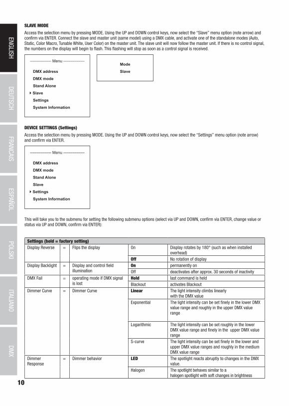
SLAVE MODE
Access the selection menu by pressing MODE. Using the UP and DOWN control keys, now select the “Slave” menu option (note arrow) and confirm via ENTER. Connect the slave and master unit (same model) using a DMX cable, and activate one of the standalone modes (Auto, Static, Color Macro, Tunable White, User Color) on the master unit. The slave unit will now follow the master unit. If there is no control signal, the numbers on the display will begin to flash. This flashing will stop as soon as a control signal is received.
---------------- Menu ----------------
DMX address
DMX mode
Stand Alone
Slave
Settings
System Information
Mode
Slave
DEVICE SETTINGS (Settings)
Access the selection menu by pressing MODE. Using the UP and DOWN control keys, now select the “Settings” menu option (note arrow) and confirm via ENTER.
---------------- Menu ----------------
DMX address
DMX mode
Stand Alone
Slave
Settings
System Information
This will take you to the submenu for setting the following submenu options (select via UP and DOWN, confirm via ENTER, change value or status via UP and DOWN, confirm via ENTER):
Settings (bold = factory setting)Display Reverse = Flips the display On Display rotates by 180° (such as when installed
overhead)Off No rotation of display
Display Backlight = Display and control field illumination
On permanently onOff deactivates after approx. 30 seconds of inactivity
DMX Fail = operating mode if DMX signal is lost
Hold last command is heldBlackout activates Blackout
Dimmer Curve = Dimmer Curve Linear The light intensity climbs linearly with the DMX value
Exponential The light intensity can be set finely in the lower DMX value range and roughly in the upper DMX value range
Logarithmic The light intensity can be set roughly in the lower DMX value range and finely in the upper DMX value range
S-curve The light intensity can be set finely in the lower and upper DMX value ranges and roughly in the medium DMX value range
DimmerResponse
= Dimmer behavior LED The spotlight reacts abruptly to changes in the DMX value.
Halogen The spotlight behaves similar to a halogen spotlight with soft changes in brightness

11
DMX
DEUTSC
HFRAN
CAIS
ESPAÑO
LEN
GLISH
ITALIANO
POLSKI
PWM Frequency = LED PWM frequency 800Hz / 1200Hz / 2000Hz / 3600Hz / 12kHz / 25kHz
Sets the LED PWM frequency
Fan = Sets fan control Auto Automatic fan controlSilent Extra quiet fan with reduced brightness, if required
Zoom Range Sets the zoom range Standard Standard zoom rangeExtended Extended zoom range
Autolock = Automatically locks the control element
On Automatically locks the control element after approx. 30 seconds of inactivity. Shown on display: “LOCKED” Lock: Press UP and DOWN at the same time for approx. 5 seconds
Off Deactivates automatic locking of the control elementCalibration = Color and zoom calibration Red, Green, Blue,
White, Zoom Individual calibration. Cross-mode configuration of R, G, B, W, and Zoom with values from 000 - 255
Zoom Reset = Initialize zoom unit Reset? Initialize zoom unit: confirm with ENTER, cancel with MODE
Factory Reset = Reset to factory settings Reset? Reset to factory settings: confirm with ENTER, cancel with MODE
linear
DMX value
Ligh
t int
ensi
ty
exponential
DMX value
Ligh
t int
ensi
ty
logarithmic
DMX valueLi
ght i
nten
sity
S-curve
DMX value
Ligh
t int
ensi
ty
Dimmer Curves
SYSTEM INFORMATION (SYSTEM INFORMATION)
Access the selection menu by pressing MODE. Using the UP and DOWN control keys, now select the “System Information” menu option (note arrow) and confirm via ENTER.
---------------- Menu ----------------
DMX address
DMX mode
Stand Alone
Slave
Settings
System Information
You can now select the desired submenu option via the UP and DOWN keys, and display the corresponding information by pressing ENTER.
System Information (bold = factory setting)
Firmware = Displays the device firmware Main CPU Vx.xx
Temperature = Displays temperature of LED unit LED LED TEMP xxxC / xxxF
Celsius/Fahrenheit Unit Celsius (= displays in degrees Celsius)
Unit Fahrenheit (= displays in degrees Fahrenheit)
Operation hours = Displays operating hours OpTime xxxx:xxh Displays the total operating time in hours and minutes
12
DMX
ITALIANOPOLSKI
ESPAÑOLFRANCAIS
DEUTSCHENGLISH
A
B
BC
A
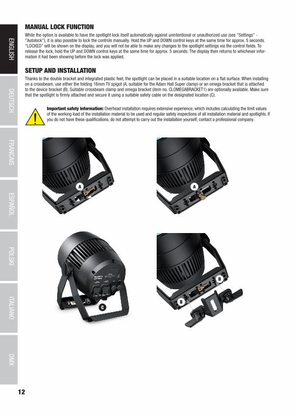
MANUAL LOCK FUNCTIONWhile the option is available to have the spotlight lock itself automatically against unintentional or unauthorized use (see "Settings" - "Autolock"), it is also possible to lock the controls manually. Hold the UP and DOWN control keys at the same time for approx. 5 seconds. “LOCKED” will be shown on the display, and you will not be able to make any changes to the spotlight settings via the control fields. To release the lock, hold the UP and DOWN control keys at the same time for approx. 5 seconds. The display then returns to whichever infor-mation it had been showing before the lock was applied.
SETUP AND INSTALLATIONThanks to the double bracket and integrated plastic feet, the spotlight can be placed in a suitable location on a flat surface. When installing on a crossbeam, use either the folding 16mm TV spigot (A, suitable for the Adam Hall Super clamp) or an omega bracket that is attached to the device bracket (B). Suitable crossbeam clamp and omega bracket (item no. CLOMEGABRACKET1) are optionally available. Make sure that the spotlight is firmly attached and secure it using a suitable safety cable on the designated location (C).
Important safety information: Overhead installation requires extensive experience, which includes calculating the limit values of the working load of the installation material to be used and regular safety inspections of all installation material and spotlights. If you do not have these qualifications, do not attempt to carry out the installation yourself; contact a professional company.

13
DMX
DEUTSC
HFRAN
CAIS
ESPAÑO
LEN
GLISH
ITALIANO
POLSKI
DMX TECHNOLOGY
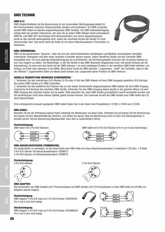
DMX-512DMX (Digital Multiplex) is the designation for a universal transmission protocol for communications between corresponding devices and controllers. A DMX controller sends DMX data to the connected DMX device(s). The DMX data is always transmitted as a serial data stream that is forwarded from one connected device to the next via the "DMX IN" and "DMX OUT" connectors (XLR plug-type connectors) that are found on every DMX-capable device, provided the maximum number of devices does not exceed 32 units. The last device in the chain needs to be equipped with a terminator (terminating resistor).
DMX CONNECTIONDMX is the common "language" via which a very wide range of types and models of equipment from various manufacturers can be connected with one another and controlled via a central controller, provided that all of the devices and the controller are DMX compatible. For optimum data transmission, it is necessary to keep the connecting cables between the individual devices as short as possible. The order in which the devices are integrated in the DMX network has no influence on the addresses. Thus the device with the DMX address 1 can be located at any position in the (serial) DMX chain: at the beginning, at the end or somewhere in the middle. If the DMX address 1 is assigned to a device, the controller "knows" that it should send all data allocated to address 1 to this device regardless of its position in the DMX network.
SERIAL CONNECTION OF MULTIPLE LIGHTS1. Connect the male XLR connector (3-pin or 5-pin) of the DMX cable to the DMX output (female XLR socket) of the first DMX device (e.g. DMX-Controller).2. Connect the female 3-pin XLR connector of the DMX cable connected to the first projector to the DMX input (male 3-pin socket) of the next DMX device. In the same way, connect the DMX output of this device to the DMX input of the next device and repeat until all devices have been connected. Please note that as a rule, DMX devices are connected in series and connections cannot be shared without active splitters. The maximum number of DMX devices in a DMX chain should not exceed 32 units.
The Adam Hall 3 STAR, 4 STAR, and 5 STAR product ranges include an extensive selection of suitable cables.
DMX CABLESWhen fabricating your own cables, always observe the illustrations on this page. Never connect the shielding of the cable to the ground contact of the plug, and always make certain that the shielding does not come into contact with the housing of the XLR plug. If the shielding is connected to the ground, this can lead to short-circuiting and system malfunctions.
Pin AssignmentDMX cable with 3-pin XLR connectors: DMX cable with 5-pin XLR connectors (pin 4 and 5 are not used):
Shield
23
1
23
1
123
45
12
34
5
Shield
DMX TERMINATORS (TERMINATING RESISTORS)To prevent system errors, the last device in a DMX chain needs to be equipped with a terminating resistor (120 ohm, 1/4 Watt).3-pin XLR connector with a terminating resistor: K3DMXT35-pin XLR connector with a terminating resistor: K3DMXT5
Pin Assignment3-pin XLR connector: 5-pin XLR connector:
23
1
12
34
5
DMX ADAPTERThe combination of DMX devices with 3-pin connectors and DMX devices with 5-pin connectors in a DMX chain is possible with suitable adapters.
Pin AssignmentDMX Adapter 5-pin XLR male to 3-pin XLR female: K3DGF0020Pins 4 and 5 are not used.
Pin AssignmentDMX Adapter 3-pin XLR male to 5-pin XLR female: K3DHM0020Pins 4 and 5 are not used.

14
DMX
ITALIANOPOLSKI
ESPAÑOLFRANCAIS
DEUTSCHENGLISH
Item number: CLZZ180G2
Product type: LED wash light
Type: Outdoor spotlight
Color spectrum of LED: RGBW
Number of LEDs: 1
LED Type: 180W COB
LED PWM frequency: 800Hz, 1200Hz, 2000Hz, 3600Hz, 12kHz, 25kHz (adjustable)
Beam angle: 10° - 40°
DMX input: 5-pin XLR, male, IP65
DMX output: 5-pin XLR, female, IP65
DMX mode: 3-channel, 4-channel, 5-channel, 9-channel, 10-channel, 11-channel, 17- channel
DMX functions: Dimmer, dimmer fine, RGBW, RGBW fine, strobe, color temperature correction, color macros, color change, color blending, zoom, zoom fine, dimming response, various system settings
Standalone functions: Color macros, auto programs, static mode, strobe, user color, tunable white, master/slave operation
System settings: Rotate display by 180°, display illumination, DMX fail, dimmer curve, dimming response, color calibration, display lock function, LED PWM frequency, zoom reset, factory reset, fan control
Controller: DMX512, RDM enabled
Control elements: MODE, ENTER, UP, DOWN (touch-sensitive control fields)
Display elements: OLED Display
Operating voltage: 100 - 240V AC / 50 - 60Hz
Power consumption: 220W
Illuminance (@ 1 m): 56790lx (narrow)
Luminous flux (RGBW): 4900lm
Power supply connection: Input and output, Power Twist connector, IP65 (output max 10A)
Ambient temperature (running): -15°C - +45°C
Housing material: Metal
Housing color: Black
Housing cooling: Temperature-controlled IP65 fan
Protection class: IP65
Dimensions (B x H x W, without mounting bracket):
240 x 240 x 254mm
Weight: 8.0 kg
Additional features: 1 m power cable with IP65 Power Twist connector, stand mounting bracket included. Integrated 16mm TV spigot. Barndoor and omega bracket optionally available
TECHNICAL SPECIFICATIONS
15
DMX
DEUTSC
HFRAN
CAIS
ESPAÑO
LEN
GLISH
ITALIANO
POLSKI
MANUFACTURER´S DECLARATIONS
MANUFACTURER‘S WARRANTY & LIMITATIONS OF LIABILITY You can find our current warranty conditions and limitations of liability at: https://cdn-shop.adamhall.com/media/pdf/MANUFACTU-RERS-DECLARATIONS_CAMEO.pdf. To request warranty service for a product, please contact Adam Hall GmbH, Adam-Hall-Str. 1, 61267 Neu Anspach / Email: [email protected] / +49 (0)6081 / 9419-0.
CORRECT DISPOSAL OF THIS PRODUCT(valid in the European Union and other European countries with a differentiated waste collection system) This symbol on the product, or on its documents indicates that the device may not be treated as household waste. This is to avoid
environmental damage or personal injury due to uncontrolled waste disposal. Please dispose of this product separately from other waste and have it recycled to promote sustainable economic activity. Household users should contact either the retailer where they purchased this product, or their local government office, for details on where and how they can recycle this item in an environmentally friendly manner. Business users should contact their supplier and check the terms and conditions of the purchase contract. This product should not be mixed with other commercial waste for disposal.
FCC STATEMENTThis device complies with Part 15 of the FCC Rules. Operation is subject to the following two conditions:(1) This device may not cause harmful interference, and(2) This device must accept any interference received, including interference that may cause undesired operation
CE ComplianceAdam Hall GmbH states that this product meets the following guidelines (where applicable):R&TTE (1999/5/EC) or RED (2014/53/EU) from June 2017Low voltage directive (2014/35/EU)EMV directive (2014/30/EU)RoHS (2011/65/EU)The complete declaration of conformity can be found at www.adamhall.com. Furthermore, you may also direct your enquiry to [email protected].

16
DMX
ITALIANOPOLSKI
ESPAÑOLFRANCAIS
DEUTSCHENGLISH
DEUTSCH
SIE HABEN DIE RICHTIGE WAHL GETROFFEN!Dieses Gerät wurde unter hohen Qualitätsanforderungen entwickelt und gefertigt, um viele Jahre einen reibungslosen Betrieb zu gewähr-leisten. Bitte lesen Sie diese Bedienungsanleitung sorgfältig, damit Sie Ihr neues Produkt von Cameo Light schnell und optimal einsetzen können. Weitere Informationen über Cameo Light erhalten Sie auf unserer Website WWW.CAMEOLIGHT.COM.
SICHERHEITSHINWEISE 1. Lesen Sie diese Anleitung bitte sorgfältig durch. 2. Bewahren Sie alle Informationen und Anleitungen an einem sicheren Ort auf. 3. Befolgen Sie die Anweisungen. 4. Beachten Sie alle Warnhinweise. Entfernen Sie keine Sicherheitshinweise oder andere Informationen vom Gerät. 5. Verwenden Sie das Gerät nur in der vorgesehenen Art und Weise. 6. Verwenden Sie ausschließlich stabile und passende Stative bzw. Befestigungen (bei Festinstallationen). Stellen Sie sicher, dass Wandhalterungen ordnungsgemäß installiert und gesichert sind. Stellen Sie sicher, dass das Gerät sicher installiert ist und nicht herunterfallen kann. 7. Beachten Sie bei der Installation die für Ihr Land geltenden Sicherheitsvorschriften. 8. Installieren und betreiben Sie das Gerät nicht in der Nähe von Heizkörpern, Wärmespeichern, Öfen oder sonstigen Wärmequellen. Sorgen Sie dafür, dass das Gerät immer so installiert ist, dass es ausreichend gekühlt wird und nicht überhitzen kann. 9. Platzieren Sie keine Zündquellen wie z.B. brennende Kerzen auf dem Gerät. 10. Lüftungsschlitze dürfen nicht blockiert werden.11. Das Gerät wurde ausschließlich für die Verwendung in Innenräumen entwickelt, betreiben Sie das Gerät nicht in unmittelbarer Nähe von Wasser (gilt nicht für spezielle Outdoor Geräte - beachten Sie in diesem Fall bitte die im Folgenden vermerkten Sonderhinweise). Bringen Sie das Gerät nicht mit brennbaren Materialien, Flüssigkeiten oder Gasen in Berührung.12. Sorgen Sie dafür, dass kein Tropf- oder Spritzwasser in das Gerät eindringen kann. Stellen Sie keine mit Flüssigkeit gefüllten Behältnisse wie Vasen oder Trinkgefäße auf das Gerät. 13. Sorgen Sie dafür, dass keine Gegenstände in das Gerät fallen können. 14. Betreiben Sie das Gerät nur mit dem vom Hersteller empfohlenen und vorgesehenen Zubehör. 15. Öffnen Sie das Gerät nicht und verändern Sie es nicht. 16. Überprüfen Sie nach dem Anschluss des Geräts alle Kabelwege, um Schäden oder Unfälle, z. B. durch Stolperfallen zu vermeiden. 17. Achten Sie beim Transport darauf, dass das Gerät nicht herunterfallen und dabei möglicherweise Sach- und Personenschäden verursachen kann.18. Wenn Ihr Gerät nicht mehr ordnungsgemäß funktioniert, Flüssigkeiten oder Gegenstände in das Geräteinnere gelangt sind, oder das Gerät anderweitig beschädigt wurde, schalten Sie es sofort aus und trennen es von der Netzsteckdose (sofern es sich um ein aktives Gerät handelt). Dieses Gerät darf nur von autorisiertem Fachpersonal repariert werden. 19. Verwenden Sie zur Reinigung des Geräts ein trockenes Tuch. 20. Beachten Sie alle in Ihrem Land geltenden Entsorgungsgesetze. Trennen Sie bei der Entsorgung der Verpackung bitte Kunststoff und Papier bzw. Kartonagen voneinander. 21. Kunststoffbeutel müssen außer Reichweite von Kindern aufbewahrt werden.
BEI GERÄTEN MIT NETZANSCHLUSS:22. ACHTUNG: Wenn das Netzkabel des Geräts mit einem Schutzkontakt ausgestattet ist, muss es an einer Steckdose mit Schutzleiter angeschlossen werden. Deaktivieren Sie niemals den Schutzleiter eines Netzkabels. 23. Schalten Sie das Gerät nicht sofort ein, wenn es starken Temperaturschwankungen ausgesetzt war (beispielsweise nach dem Transport). Feuchtigkeit und Kondensat könnten das Gerät beschädigen. Schalten Sie das Gerät erst ein, wenn es Zimmertemperatur erreicht hat. 24. Bevor Sie das Gerät an die Steckdose anschließen, prüfen Sie zuerst, ob die Spannung und die Frequenz des Stromnetzes mit den auf dem Gerät angegebenen Werten übereinstimmen. Verfügt das Gerät über einen Spannungswahlschalter, schließen Sie das Gerät nur an die Steckdose an, wenn die Gerätewerte mit den Werten des Stromnetzes übereinstimmen. Wenn das mitgelieferte Netzkabel bzw. der mitgelie-ferte Netzadapter nicht in Ihre Netzsteckdose passt, wenden Sie sich an Ihren Elektriker. 25. Treten Sie nicht auf das Netzkabel. Sorgen Sie dafür, dass spannungsführende Kabel speziell an der Netzbuchse bzw. am Netzadapter und der Gerätebuchse nicht geknickt werden. 26. Achten Sie bei der Verkabelung des Geräts immer darauf, dass das Netzkabel bzw. der Netzadapter stets frei zugänglich ist. Trennen Sie das Gerät stets von der Stromzuführung, wenn das Gerät nicht benutzt wird, oder Sie das Gerät reinigen möchten. Ziehen Sie Netzkabel und Netzadapter immer am Stecker bzw. am Adapter und nicht am Kabel aus der Steckdose. Berühren Sie Netzkabel und Netzadapter niemals mit nassen Händen. 27. Schalten Sie das Gerät möglichst nicht schnell hintereinander ein und aus, da sonst die Lebensdauer des Geräts beeinträchtigt werden könnte.28. WICHTIGER HINWEIS: Ersetzen Sie Sicherungen ausschließlich durch Sicherungen des gleichen Typs und Wertes. Sollte eine Sicherung wiederholt auslösen, wenden Sie sich bitte an ein autorisiertes Servicezentrum. 29. Um das Gerät vollständig vom Stromnetz zu trennen, entfernen Sie das Netzkabel bzw. den Netzadapter aus der Steckdose. 30. Wenn Ihr Gerät mit einem Volex-Netzanschluss bestückt ist, muss der passende Volex-Gerätestecker entsperrt werden, bevor er entfernt werden kann. Das bedeutet aber auch, dass das Gerät durch ein Ziehen am Netzkabel verrutschen und herunterfallen kann, wodurch Perso-nen verletzt werden und/oder andere Schäden auftreten können. Verlegen Sie Ihre Kabel daher immer sorgfältig. 31. Entfernen Sie Netzkabel und Netzadapter aus der Steckdose bei Gefahr eines Blitzschlags oder wenn Sie das Gerät länger nicht verwenden.32. Das Gerät darf nur im spannungsfreien Zustand (Trennung des Netzsteckers vom Stromnetz) installiert werden.33. Staub und andere Ablagerungen im Inneren des Geräts können es beschädigen. Das Gerät sollte je nach Umgebungsbedingungen (Staub, Nikotin, Nebel etc.) regelmäßig von qualifiziertem Fachpersonal gewartet bzw. gesäubert werden (keine Garantieleistung), um Überhitzung und Fehlfunktionen zu vermeiden.
17
DMX
DEUTSC
HFRAN
CAIS
ESPAÑO
LEN
GLISH
ITALIANO
POLSKI
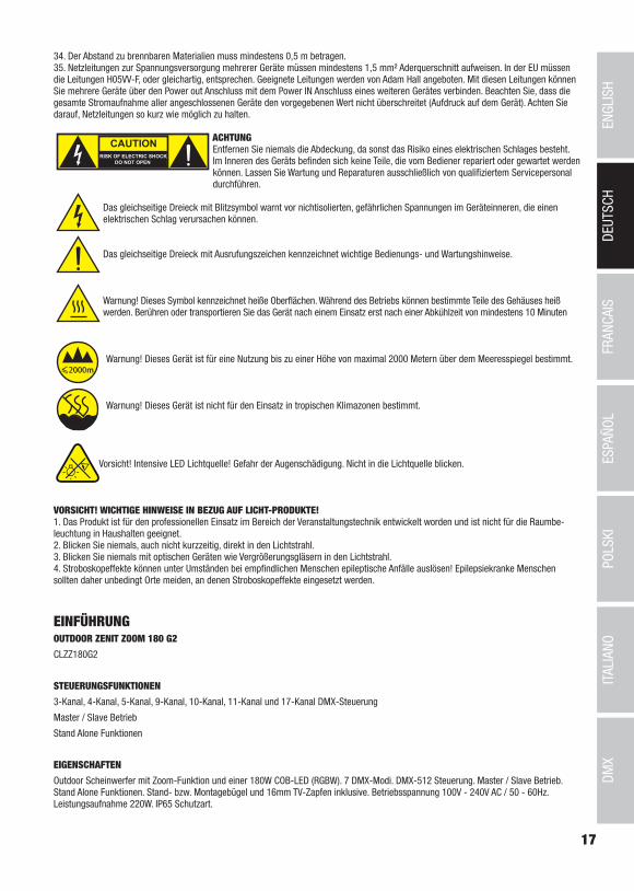
34. Der Abstand zu brennbaren Materialien muss mindestens 0,5 m betragen.35. Netzleitungen zur Spannungsversorgung mehrerer Geräte müssen mindestens 1,5 mm² Aderquerschnitt aufweisen. In der EU müssen die Leitungen H05VV-F, oder gleichartig, entsprechen. Geeignete Leitungen werden von Adam Hall angeboten. Mit diesen Leitungen können Sie mehrere Geräte über den Power out Anschluss mit dem Power IN Anschluss eines weiteren Gerätes verbinden. Beachten Sie, dass die gesamte Stromaufnahme aller angeschlossenen Geräte den vorgegebenen Wert nicht überschreitet (Aufdruck auf dem Gerät). Achten Sie darauf, Netzleitungen so kurz wie möglich zu halten.
ACHTUNGEntfernen Sie niemals die Abdeckung, da sonst das Risiko eines elektrischen Schlages besteht. Im Inneren des Geräts befinden sich keine Teile, die vom Bediener repariert oder gewartet werden können. Lassen Sie Wartung und Reparaturen ausschließlich von qualifiziertem Servicepersonal durchführen.
Das gleichseitige Dreieck mit Blitzsymbol warnt vor nichtisolierten, gefährlichen Spannungen im Geräteinneren, die einen elektrischen Schlag verursachen können.
Das gleichseitige Dreieck mit Ausrufungszeichen kennzeichnet wichtige Bedienungs- und Wartungshinweise.
Warnung! Dieses Symbol kennzeichnet heiße Oberflächen. Während des Betriebs können bestimmte Teile des Gehäuses heiß werden. Berühren oder transportieren Sie das Gerät nach einem Einsatz erst nach einer Abkühlzeit von mindestens 10 Minuten
Warnung! Dieses Gerät ist für eine Nutzung bis zu einer Höhe von maximal 2000 Metern über dem Meeresspiegel bestimmt.
Warnung! Dieses Gerät ist nicht für den Einsatz in tropischen Klimazonen bestimmt.
Vorsicht! Intensive LED Lichtquelle! Gefahr der Augenschädigung. Nicht in die Lichtquelle blicken.
VORSICHT! WICHTIGE HINWEISE IN BEZUG AUF LICHT-PRODUKTE!1. Das Produkt ist für den professionellen Einsatz im Bereich der Veranstaltungstechnik entwickelt worden und ist nicht für die Raumbe-leuchtung in Haushalten geeignet.2. Blicken Sie niemals, auch nicht kurzzeitig, direkt in den Lichtstrahl. 3. Blicken Sie niemals mit optischen Geräten wie Vergrößerungsgläsern in den Lichtstrahl.4. Stroboskopeffekte können unter Umständen bei empfindlichen Menschen epileptische Anfälle auslösen! Epilepsiekranke Menschen sollten daher unbedingt Orte meiden, an denen Stroboskopeffekte eingesetzt werden.
EINFÜHRUNGOUTDOOR ZENIT ZOOM 180 G2
CLZZ180G2
STEUERUNGSFUNKTIONEN
3-Kanal, 4-Kanal, 5-Kanal, 9-Kanal, 10-Kanal, 11-Kanal und 17-Kanal DMX-Steuerung
Master / Slave Betrieb
Stand Alone Funktionen
EIGENSCHAFTEN
Outdoor Scheinwerfer mit Zoom-Funktion und einer 180W COB-LED (RGBW). 7 DMX-Modi. DMX-512 Steuerung. Master / Slave Betrieb. Stand Alone Funktionen. Stand- bzw. Montagebügel und 16mm TV-Zapfen inklusive. Betriebsspannung 100V - 240V AC / 50 - 60Hz. Leistungsaufnahme 220W. IP65 Schutzart.

18
DMX
ITALIANOPOLSKI
ESPAÑOLFRANCAIS
DEUTSCHENGLISH
5
1 2 3 44
7
8
6
Die Scheinwerfer verfügen über den RDM-Standard (Remote Device Management). Diese Gerätefernverwaltung ermöglicht die Statusabfra-ge und Konfiguration von RDM-Endgeräten über einen RDM-fähigen Controller.
ANSCHLÜSSE, BEDIEN- UND ANZEIGEELEMENTE
1 POWER IN
IP65 Power Twist Netzeingangsbuchse mit Gummidichtkappe. Betriebsspannung 100 - 240V AC / 50 - 60Hz. Anschluss mit Hilfe des mitge-lieferten Netzkabels (bei Nichtgebrauch stets mit der Gummidichtkappe verschließen).
2 POWER OUT
IP65 Power Twist Netzausgangsbuchse mit Gummidichtkappe. Dient der Netzversorgung weiterer CAMEO Scheinwerfer. Achten Sie darauf, dass die gesamte Stromaufnahme aller angeschlossenen Geräte den auf dem Gerät in Ampere (A) angegebenen Wert nicht überschreitet (bei Nichtgebrauch stets mit der Gummidichtkappe verschließen).
3 DMX IN
Männliche IP65 5-Pol XLR-Buchse zum Anschließen eines DMX-Kontrollgeräts (z.B. DMX-Pult, bei Nichtgebrauch stets mit der Gummidicht-kappe verschließen).
4 DMX OUT
Weibliche IP65 5-Pol XLR-Buchse zum Weiterleiten des DMX-Steuersignals (bei Nichtgebrauch stets mit der Gummidichtkappe verschließen).
5 OLED-DISPLAY
Zeigt den aktuellen Betriebsmodus und weitere Systemeinstellungen an.
19
DMX
DEUTSC
HFRAN
CAIS
ESPAÑO
LEN
GLISH
ITALIANO
POLSKI
6 BERÜHRUNGSEMPFINDLICHE BEDIENFELDER MIT HINTERLEUCHTUNG
MODE
Durch Drücken auf MODE gelangen Sie in das Auswahl-Menü für Systemeinstellungen. Durch wiederholtes Drücken gelangen Sie zurück zur Hauptanzeige.
ENTER
Durch Drücken auf ENTER gelangen Sie auf die Menü-Ebene um Wertänderungen vornehmen zu können und um eines der Untermenüs zu erreichen. Wertänderungen bestätigen Sie ebenfalls durch Drücken auf ENTER.
UP und DOWN
Auswählen der einzelnen Menüpunkte im Auswahl-Menü (DMX-Adresse, Betriebsart usw.) und in den Untermenüs. Ermöglichen es, den Wert eines Menü-Punkts, wie z.B. die DMX-Adresse, wunschgemäß zu verändern.
7 DRUCKAUSGLEICHSELEMENT
Druckausgleichselement zur Vermeidung von Kondenswasserbildung im Gehäuseinneren. Um die einwandfreie Funktion zu gewährleisten, ist das Element vor Verschmutzung zu schützen.
8 SICHERUNGSÖSE
Sichern Sie das Gerät bei Überkopfmontage mit einem geeigneten Sicherungsseil an der Sicherungsöse.
9 GEHÄUSELÜFTER
Der IP65 Gehäuselüfter befindet sich in der Kühleinheit zwischen der Einheit mit Steuerung und der Einheit mit LED, Zoom und Linse. Um eine einwandfreie Funktion des Lüfters und die Luftzirkulation zu gewährleisten, decken Sie das Gerät nicht ab und halten die Lüftungs-schlitze frei von Verunreinigungen.
HINWEISE: Um den Spritzwasserschutz nach Schutzklasse IP65 bei den DMX-Buchsen zu gewährleisten, müssen die speziellen DMX Eingangs- und Ausgangsbuchsen korrekt mit den IP65 Spezial-XLR-Steckern verschlossen sein, bzw. die Gummidichtkappen zum Verschließen verwendet werden. Die Netzbuchsen POWER IN und POWER OUT sind in korrekt gestecktem Zustand spritzwassergeschützt nach IP65, ebenso bei korrekter Verwendung der Gummidichtkappen.
9
BEDIENUNGANMERKUNGEN
• Sobald der Scheinwerfer korrekt am Stromnetz angeschlossen ist, werden während des Startvorgangs nacheinander „Update Wait...“ (nur für Servicezwecke), „Welcome to Cameo“, die Modellbezeichnung und die Software Version im Display angezeigt. Außerdem wird beim Startvorgang die Zoom-Einheit initialisiert. Nach diesem Vorgang ist der Scheinwerfer betriebsbereit und startet in der Betriebsart, die zuvor angewählt war.
• Ist eine der DMX-Betriebsarten aktiviert und es liegt kein DMX-Signal am DMX-Eingang an, beginnt das Display nach wenigen Sekunden zu blinken.
• Nach ca. 30 Sekunden Inaktivität zeigt das Display automatisch die aktuell aktivierte Betriebsart an (Hauptanzeige).
• Fast Access Feature: Um die Menüführung zu vereinfachen, verfügt das Gerät über eine intelligente Menüstruktur, die es ermöglicht, auf Menüpunkte und Untermenüpunkte, die zuletzt ausgewählt waren, direkt zugreifen zu können. 1. Durch gleichzeitiges Drücken auf MODE und ENTER gelangen Sie direkt zu dem Untermenüpunkt, der zuletzt editiert wurde und können den entsprechenden Wert augenblicklich nach Wunsch ändern (DMX-Startadresse und alle Betriebsarten). 2. Durch Drücken auf MODE gelangen Sie direkt zu dem Menüpunkt, der als Letztes angewählt und editiert wurde.
• Achten Sie vor dem Ändern von Geräteeinstellungen darauf, dass die Bedieneinheit trocken und staubfrei ist, um ihre Funktionalität nicht zu beeinträchtigen.
• Die Display-Anzeige kann durch Drücken auf UP um 180° gedreht werden, wenn im Display die Hauptanzeige abgebildet wird.

20
DMX
ITALIANOPOLSKI
ESPAÑOLFRANCAIS
DEUTSCHENGLISH
DMX STARTADRESSE EINSTELLEN (DMX Address)
Durch Drücken auf MODE gelangen Sie in das Auswahl-Menü. Wählen Sie nun den Menüpunkt „DMX Address“ (Pfeil beachten) mit Hilfe der Bedienfelder UP und DOWN aus und drücken auf ENTER. Wählen Sie jetzt die gewünschte DMX-Startadresse wiederum mit Hilfe von UP und DOWN aus und bestätigen mit ENTER (der höchste Wert ist abhängig von der angewählten DMX-Betriebsart). Gleichzeitig wird die DMX-Betriebsart gestartet und der zuletzt ausgewählte DMX-Modus aktiviert.
---------------- Menu ----------------
DMX Address
DMX Mode
Stand Alone
Slave
Settings
System Information
001
5xx- DMX Address
001
DMX BETRIEBSART EINSTELLEN (DMX Mode)
Durch Drücken auf MODE gelangen Sie in das Auswahl-Menü. Wählen Sie nun den Menüpunkt „DMX Mode“ (Pfeil beachten) mit Hilfe der Bedienfelder UP und DOWN aus und drücken auf ENTER. Die gewünschte DMX-Betriebsart wählen Sie jetzt abermals mit Hilfe von UP und DOWN aus und bestätigen mit ENTER. Ausführliche DMX-Tabellen finden Sie in dieser Anleitung unter „DMX STEUERUNG“.
---------------- Menu ----------------
DMX Address
DMX Mode
Stand Alone
Slave
Settings
System Information
------------- DMX Mode -----------
3 CH
4 CH
5 CH
9 CH
10 CH
11 CH
17CH
STAND-ALONE-BETRIEBSART EINSTELLEN (Stand Alone)
Durch Drücken auf MODE gelangen Sie in das Auswahl-Menu für die Geräteeinstellungen (--- Menu ---). Mit Hilfe der Bedienfelder UP und DOWN wählen Sie nun den Menu-Punkt „Stand Alone“ aus (Pfeil beachten) und bestätigen mit ENTER. Im Untermenü können Sie nun unter den Stand-Alone-Betriebsarten „Auto“, „Colour Macro“, „Static“, „Tunable White“, und „User Colour“ mit UP und DOWN auswählen. Bestätigen Sie die Auswahl mit ENTER.
---------------- Menu ----------------
DMX Address
DMX Mode
Stand Alone
Slave
Settings
System Information
------------- Stand Alone -----------
Auto
Static
Colour Macro
Tunable White
User Colour
21
DMX
DEUTSC
HFRAN
CAIS
ESPAÑO
LEN
GLISH
ITALIANO
POLSKI
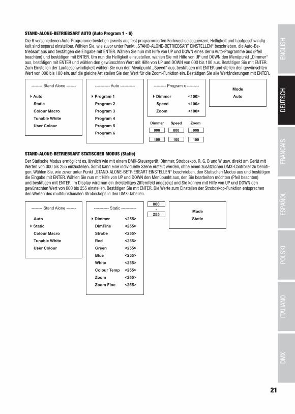
STAND-ALONE-BETRIEBSART AUTO (Auto Program 1 - 6)
Die 6 verschiedenen Auto-Programme bestehen jeweils aus fest programmierten Farbwechselsequenzen, Helligkeit und Laufgeschwindig-keit sind separat einstellbar. Wählen Sie, wie zuvor unter Punkt „STAND-ALONE-BETRIEBSART EINSTELLEN“ beschrieben, die Auto-Be-triebsart aus und bestätigen die Eingabe mit ENTER. Wählen Sie nun mit Hilfe von UP und DOWN eines der 6 Auto-Programme aus (Pfeil beachten) und bestätigen mit ENTER. Um nun die Helligkeit einzustellen, wählen Sie mit Hilfe von UP und DOWN den Menüpunkt „Dimmer“ aus, bestätigen mit ENTER und wählen den gewünschten Wert mit Hilfe von UP und DOWN von 000 bis 100 aus. Bestätigen Sie mit ENTER. Zum Einstellen der Laufgeschwindigkeit wählen Sie nun den Menüpunkt „Speed“ aus, bestätigen mit ENTER und stellen den gewünschten Wert von 000 bis 100 ein, auf die gleiche Art stellen Sie den Wert für die Zoom-Funktion ein. Bestätigen Sie alle Wertänderungen mit ENTER.
Mode
Auto
-------- Stand Alone -------
Auto
Static
Colour Macro
Tunable White
User Colour
----------- Auto -----------
Program 1
Program 2
Program 3
Program 4
Program 5
Program 6
--------- Program x ---------
Dimmer <100>
Speed <100>
Zoom <100>
000
100-
Dimmer Speed
000
100-
STAND-ALONE-BETRIEBSART STATISCHER MODUS (Static)
Der Statische Modus ermöglicht es, ähnlich wie mit einem DMX-Steuergerät, Dimmer, Stroboskop, R, G, B und W usw. direkt am Gerät mit Werten von 000 bis 255 einzustellen. Somit kann eine individuelle Szene erstellt werden, ohne einen zusätzlichen DMX-Controller zu benöti-gen. Wählen Sie, wie zuvor unter Punkt „STAND-ALONE-BETRIEBSART EINSTELLEN“ beschrieben, den Statischen Modus aus und bestätigen die Eingabe mit ENTER. Wählen Sie nun mit Hilfe von UP und DOWN den Menüpunkt aus, den Sie bearbeiten möchten (Pfeil beachten) und bestätigen mit ENTER. Im Display wird nun ein dreistelliges Ziffernfeld angezeigt und Sie können mit Hilfe von UP und DOWN den gewünschten Wert von 000 bis 255 einstellen. Bestätigen Sie mit ENTER. Die Werte zum Einstellen der Stroboskop-Funktion entsprechen den Werten des multifunktionalen Stroboskops in den DMX-Tabellen.
Mode
Static
-------- Stand Alone -------
Auto
Static
Colour Macro
Tunable White
User Colour
----------- Static -----------
Dimmer <255>
DimFine <255>
Strobe <255>
Red <255>
Green <255>
Blue <255>
White <255>
Colour Temp <255>
Zoom <255>
Zoom Fine <255>
000
255-
Zoom
000
100-

22
DMX
ITALIANOPOLSKI
ESPAÑOLFRANCAIS
DEUTSCHENGLISH
STAND-ALONE-BETRIEBSART FARBMAKROS (Colour Macro)
15 verschiedene Farbmakros stehen als Preset zur Verfügung. Wählen Sie, wie zuvor unter Punkt BETRIEBSART EINSTELLEN beschrieben, den Menüpunkt „Colour Macro“ aus und bestätigen die Eingabe mit ENTER. Wählen Sie nun mit Hilfe von UP und DOWN die gewünschte Farbe als Preset aus (Pfeil beachten) und bestätigen mit ENTER (Colour Off = Blackout). Im Display wird nun ein dreistelliges Ziffernfeld angezeigt und Sie können mit Hilfe von UP und DOWN die gewünschte Helligkeit von 000 bis 100 einstellen. Bestätigen Sie mit ENTER. Die Einstellung der Zoom-Funktion erfolgt in gleicher Weise.
Mode
Colour Macro
------- Stand Alone ------
Auto
Static
Colour Macro
Tunable White
User Colour
----- Colour Macro -----
Colour Off
Red <100>
Amber <100>
Yellow Warm <100>
Yellow <100>
Green <100>
Turquoise <100>
Cyan <100>
000
100-
Blue <100>
Lavender <100>
Mauve <100>
Magenta <100>
Pink <100>
Warm White <100>
White <100>
Cold White <100>
Zoom <100>
STAND-ALONE-BETRIEBSART FARBTEMPERATUR (Tunable White)
Der Farbtemperatur Modus ermöglicht es, Licht mit einer Farbtemperatur von Kaltweiß bis Warmweiß (CTC), die Helligkeit (Dimmer) und die Zoom-Funktion direkt am Gerät einzustellen. Wählen Sie, wie zuvor unter Punkt “STAND-ALONE-BETRIEBSART EINSTELLEN” beschrieben, den Farbtemperatur Modus aus und bestätigen die Eingabe mit ENTER. Wählen Sie nun mit Hilfe von UP und DOWN den Menüpunkt aus, den Sie bearbeiten möchten (Pfeil beachten) und bestätigen mit ENTER. Im Display wird nun ein dreistelliges Ziffernfeld angezeigt und Sie können mit Hilfe von UP und DOWN den gewünschten Wert einstellen. Bestätigen Sie mit ENTER.
Mode
Tunable White
------- Stand Alone ------
Auto
Static
Colour Macro
Tunable White
User Colour
----- Tunable White -----
Dimmer <100>
CTC <100>
Zoom <100>
000
100-
STAND-ALONE-BETRIEBSART BENUTZER-PRESETS (User Colour)
Die Stand-Alone-Betriebsart “Benutzer-Presets” ermöglicht es, Gesamthelligkeit und eine Farbmischung aus R, G, B und W usw. direkt im Gerät in vier individuellen Farb-Presets abspeichern zu können. Wählen Sie, wie zuvor unter Punkt „STAND-ALONE-BETRIEBSART EINSTELLEN“ beschrieben, den Menüpunkt “User Colour” aus und bestätigen die Eingabe mit ENTER. Wählen Sie nun mit Hilfe von UP und DOWN einen der Speicherplätze Colour 1 bis Colour 4 aus, bestätigen mit ENTER und wählen den Untermenüpunkt aus, den Sie bearbeiten möchten (Pfeil beachten). Bestätigen Sie mit ENTER. Im Display wird nun ein dreistelliges Ziffernfeld angezeigt und Sie können mit Hilfe von UP und DOWN den Wert nach Wunsch von 000 bis 255 einstellen. Bestätigen Sie wiederum mit ENTER. Die Werte zum Einstellen der Stroboskop-Funktion entsprechen den Werten des multifunktionalen Stroboskops in den DMX-Tabellen.
Mode
User Colour
------- Stand Alone ------
Auto
Static
Colour Macro
Tunable White
User Colour
--------- Colour 1 ---------
Dimmer <255>
DimFine <255>
Strobe <255>
Red <255>
Green <255>
Blue <255>
White <255>
Colour Temp <255>
Zoom <255>
Zoom Fine <255>
000
255-------- User Colour -------
Colour 1
Colour 2
Colour 3
Colour 4

23
DMX
DEUTSC
HFRAN
CAIS
ESPAÑO
LEN
GLISH
ITALIANO
POLSKI
SLAVE BETRIEBSART
Durch Drücken auf MODE gelangen Sie in das Auswahl-Menü. Mit Hilfe der Bedienfelder UP und DOWN wählen Sie nun den Menü-Punkt „Slave“ aus (Pfeil beachten) und bestätigen mit ENTER. Verbinden Sie die Slave- und die Master-Einheit (gleiches Modell) mit Hilfe eines DMX-Kabels und aktivieren in der Master-Einheit eine der Stand-Alone Betriebsarten (Auto, Static, Colour Macro, Tunable White, User Colour). Nun folgt die Slave-Einheit der Master-Einheit. Liegt kein Steuersignal an, beginnen die Zeichen im Display zu blinken, das Blinken stoppt, sobald ein Steuersignal anliegt.
---------------- Menu ----------------
DMX Address
DMX Mode
Stand Alone
Slave
Settings
System Information
Mode
Slave
GERÄTEEINSTELLUNGEN (Settings)
Durch Drücken auf MODE gelangen Sie in das Auswahl-Menü. Mit Hilfe der Bedienfelder UP und DOWN wählen Sie nun den Menü-Punkt „Settings“ aus (Pfeil beachten) und bestätigen mit ENTER.
---------------- Menu ----------------
DMX Address
DMX Mode
Stand Alone
Slave
Settings
System Information
Daraufhin gelangen Sie in das Untermenü zum Einstellen folgender Untermenüpunkte (Auswahl mit UP und DOWN, bestätigen mit ENTER, Wert bzw. Status ändern mit UP und DOWN, bestätigen mit ENTER):
Settings (Fettdruck = Werkseinstellung)Display Reverse = Drehung der Display-Anzeige On Drehung der Display-Anzeige um 180° (z.B. Kop-
fübermontage)Off keine Drehung der Display-Anzeige
Display Backlight = Display- und Bedienfeldbe-leuchtung
On permanent anOff Deaktivierung nach ca. 30 Sekunden Inaktivität
DMX Fail = Betriebszustand bei DMX-Sig-nal-Unterbrechung
Hold letzter Befehl wird gehaltenBlackout aktiviert Blackout
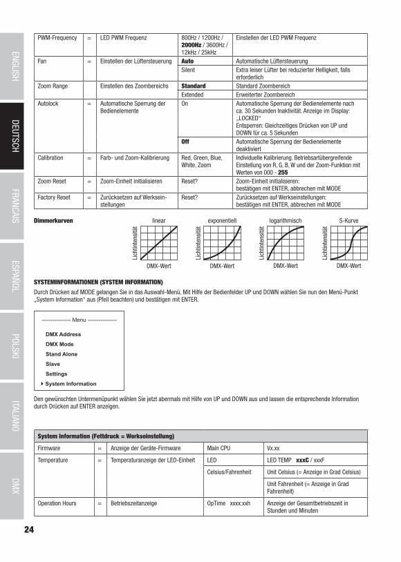
Dimmer Curve = Dimmerkurve Linear Die Lichtintensität steigt linear mit dem DMX-Wert an
Exponential Die Lichtintensität lässt sich im unteren DMX-Wert-bereich fein und im oberen DMX-Wertbereich grob einstellen
Logarithmic Die Lichtintensität lässt sich im unteren DMX-Wert-bereich grob und im oberen DMX-Wertbereich fein einstellen
S-Curve Die Lichtintensität lässt sich im unteren und oberen DMX-Wertbereich fein und im mittleren DMX-Wert-bereich grob einstellen
DimmerResponse
= Dimmverhalten LED Der Strahler reagiert abrupt auf Änderungen des DMX-Werts
Halogen Der Strahler verhält sich ähnlich einem Halogenstrahler mit sanften Helligkeitsänderungen
24
DMX
ITALIANOPOLSKI
ESPAÑOLFRANCAIS
DEUTSCHENGLISH
PWM-Frequency = LED PWM Frequenz 800Hz / 1200Hz / 2000Hz / 3600Hz / 12kHz / 25kHz
Einstellen der LED PWM Frequenz
Fan = Einstellen der Lüftersteuerung Auto Automatische LüftersteuerungSilent Extra leiser Lüfter bei reduzierter Helligkeit, falls
erforderlichZoom Range Einstellen des Zoombereichs Standard Standard Zoombereich
Extended Erweiterter ZoombereichAutolock = Automatische Sperrung der
BedienelementeOn Automatische Sperrung der Bedienelemente nach
ca. 30 Sekunden Inaktivität. Anzeige im Display: „LOCKED“ Entsperren: Gleichzeitiges Drücken von UP und DOWN für ca. 5 Sekunden
Off Automatische Sperrung der Bedienelemente deaktiviert
Calibration = Farb- und Zoom-Kalibrierung Red, Green, Blue, White, Zoom
Individuelle Kalibrierung. Betriebsartübergreifende Einstellung von R, G, B, W und der Zoom-Funktion mit Werten von 000 - 255
Zoom Reset = Zoom-Einheit initialisieren Reset? Zoom-Einheit initialisieren: bestätigen mit ENTER, abbrechen mit MODE
Factory Reset = Zurücksetzen auf Werksein-stellungen
Reset? Zurücksetzen auf Werkseinstellungen: bestätigen mit ENTER, abbrechen mit MODE
linear
DMX-Wert
Lich
tinte
nsitä
t
exponentiell
DMX-Wert
Lich
tinte
nsitä
t
logarithmisch
DMX-WertLi
chtin
tens
ität
S-Kurve
DMX-Wert
Lich
tinte
nsitä
t
Dimmerkurven
SYSTEMINFORMATIONEN (SYSTEM INFORMATION)
Durch Drücken auf MODE gelangen Sie in das Auswahl-Menü. Mit Hilfe der Bedienfelder UP und DOWN wählen Sie nun den Menü-Punkt „System Information“ aus (Pfeil beachten) und bestätigen mit ENTER.
---------------- Menu ----------------
DMX Address
DMX Mode
Stand Alone
Slave
Settings
System Information
Den gewünschten Untermenüpunkt wählen Sie jetzt abermals mit Hilfe von UP und DOWN aus und lassen die entsprechende Information durch Drücken auf ENTER anzeigen.
System Information (Fettdruck = Werkseinstellung)
Firmware = Anzeige der Geräte-Firmware Main CPU Vx.xx
Temperature = Temperaturanzeige der LED-Einheit LED LED TEMP xxxC / xxxF
Celsius/Fahrenheit Unit Celsius (= Anzeige in Grad Celsius)
Unit Fahrenheit (= Anzeige in Grad Fahrenheit)
Operation Hours = Betriebszeitanzeige OpTime xxxx:xxh Anzeige der Gesamtbetriebszeit in Stunden und Minuten
25
DMX
DEUTSC
HFRAN
CAIS
ESPAÑO
LEN
GLISH
ITALIANO
POLSKI
A
B
BC
A
MANUELLE SPERR-FUNKTIONNeben der Möglichkeit, den Scheinwerfer automatisch vor versehentlicher und unbefugter Bedienung zu schützen (siehe „Settings“ - „Autolock“), kann die Sperrung der Bedienelemente auch manuell erfolgen. Halten Sie für ca. 5 Sekunden die Bedienfelder UP und DOWN gleichzeitig gedrückt. Nun wird dauerhaft „LOCKED“ im Display angezeigt und eine Änderung der Einstellungen des Scheinwerfers über die Bedienfelder ist nicht mehr möglich. Um die Sperre aufzuheben, halten Sie wiederum für ca. 5 Sekunden die Bedienfelder UP und DOWN gleichzeitig gedrückt. Die Anzeige im Display wechselt nun zur zuvor angezeigten Information.
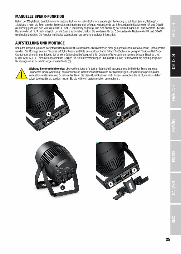
AUFSTELLUNG UND MONTAGEDank des Doppelbügels und der integrierten Kunststofffüße kann der Scheinwerfer an einer geeigneten Stelle auf eine ebene Fläche gestellt werden. Die Montage an einer Traverse erfolgt entweder mit Hilfe des ausklappbaren 16mm TV-Zapfens (A, geeignet für Adam Hall Super Clamp) oder eines Omega-Bügels, der an dem Gerätebügel befestigt wird (B). Geeignete Traversenklemmen und Omega-Bügel (Art. Nr. CLOMEGABRACKET1) sind optional erhältlich. Sorgen Sie für feste Verbindungen und sichern Sie den Scheinwerfer mit einem geeigneten Sicherungsseil an der dafür vorgesehenen Stelle (C).
Wichtige Sicherheitshinweise: Überkopfmontage erfordert umfassende Erfahrung, einschließlich der Berechnung der Grenzwerte für die Arbeitslast, des verwendeten Installationsmaterials und der regelmäßigen Sicherheitsüberprüfung aller Installationsmaterialien und Scheinwerfer. Wenn Sie diese Qualifikationen nicht haben, versuchen Sie nicht, eine Installation selbst durchzuführen, sondern nutzen Sie die Hilfe von professionellen Unternehmen.
26
DMX
ITALIANOPOLSKI
ESPAÑOLFRANCAIS
DEUTSCHENGLISH
DMX TECHNIK
DMX-512DMX (Digital Multiplex) ist die Bezeichnung für ein universelles Übertragungsprotokoll für die Kommunikation zwischen entsprechenden Geräten und Controllern. Ein DMX-Controller sendet DMX-Daten an das/die angeschlossene(n) DMX-Gerät(e). Die DMX-Datenübertragung erfolgt stets als serieller Datenstrom, der über die an jedem DMX-fähigen Gerät vorhandenen DMX IN- und DMX OUT-Anschlüsse (XLR-Steckverbinder) von einem angeschlossenen Gerät an das nächste weitergeleitet wird, wobei die maximale Anzahl der Geräte 32 nicht überschreiten darf. Das letzte Gerät der Kette ist mit einem Abschlussstecker (Terminator) zu bestücken.
DMX-VERBINDUNG:DMX ist die gemeinsame "Sprache", über die sich die unterschiedlichsten Gerätetypen und Modelle verschiedener Hersteller miteinander verkoppeln und über einen zentralen Controller steuern lassen, sofern sämtliche Geräte und der Controller DMX-kompatibel sind. Für eine optimale Datenübertragung ist es erforderlich, die Verbindungskabel zwischen den einzelnen Geräten so kurz wie möglich zu halten. Die Reihenfolge, in der die Geräte in das DMX-Netzwerk eingebunden sind, hat keinen Einfluss auf die Adressierung. So kann sich das Gerät mit der DMX-Adresse 1 an einer beliebigen Position in der (seriellen) DMX-Kette befinden, am Anfang, am Ende oder irgendwo in der Mitte. Wird einem Gerät die DMX-Adresse 1 zugewiesen, "weiß" der Controller, dass er alle der Adresse 1 zugeordneten Daten an dieses Gerät senden soll, ungeachtet seiner Position im DMX-Verbund.
SERIELLE VERKOPPLUNG MEHRERER SCHEINWERFER1. Verbinden Sie den männlichen XLR-Stecker (3-Pol oder 5-Pol) des DMX-Kabels mit dem DMX-Ausgang (weibliche XLR-Buchse) des ersten DMX-Geräts (z.B. DMX-Controller).2. Verbinden Sie den weibliche XLR-Stecker des an den ersten Scheinwerfer angeschlossenen DMX-Kabels mit dem DMX-Eingang (männliche XLR-Buchse) des nächsten DMX-Geräts. Verbinden Sie den DMX-Ausgang dieses Geräts in der gleichen Weise mit dem DMX-Eingang des nächsten Geräts und so weiter. Bitte beachten Sie, dass DMX-Geräte grundsätzlich seriell verschaltet werden und die Verbindungen nicht ohne aktiven Splitter geteilt werden können. Die maximale Anzahl der DMX-Geräte einer DMX-Kette darf 32 nicht überschreiten.
Eine umfangreiche Auswahl geeigneter DMX-Kabel finden Sie in den Adam Hall Produktlinien 3 STAR, 4 STAR und 5 STAR.
DMX-KABEL:Beachten Sie bei der Anfertigung eigener Kabel unbedingt die Abbildungen auf dieser Seite. Verbinden Sie auf keinen Fall die Abschirmung des Kabels mit dem Massekontakt des Steckers, und achten Sie darauf, dass die Abschirmung nicht mit dem XLR-Steckergehäuse in Kontakt kommt. Hat die Abschirmung Massekontakt, kann dies zu Systemfehlern führen.
Steckerbelegung:DMX-Kabel mit 3-Pol XLR-Steckern: DMX-Kabel mit 5-Pol XLR-Steckern (Pin 4 und 5 sind nicht belegt.):
Shield
23
1
23
1
123
45
12
34
5
Shield
DMX-ABSCHLUSSSTECKER (TERMINATOR):Um Systemfehler zu vermeiden, ist das letzte Gerät einer DMX-Kette mit einem Abschlusswiderstand zu bestücken (120 Ohm, 1/4 Watt).3-Pol XLR-Stecker mit Abschlusswiderstand: K3DMXT35-Pol XLR-Stecker mit Abschlusswiderstand: K3DMXT5
Steckerbelegung:3-Pol XLR-Stecker: 5-Pol XLR-Stecker:
23
1
12
34
5
DMX-ADAPTER:Die Kombination von DMX-Geräten mit 3-Pol Anschlüssen und DMX-Geräten mit 5-Pol Anschlüssen in einer DMX-Kette ist mit Hilfe von Adaptern ebenso möglich.
SteckerbelegungDMX-Adapter 5-Pol XLR male auf 3-Pol XLR female: K3DGF0020Pin 4 und 5 sind nicht belegt.
SteckerbelegungDMX-Adapter 3-Pol XLR male auf 5-Pol XLR female: K3DHM0020Pin 4 und 5 sind nicht belegt.

27
DMX
DEUTSC
HFRAN
CAIS
ESPAÑO
LEN
GLISH
ITALIANO
POLSKI
Artikelnummer: CLZZ180G2
Produktart: LED Wash Light
Typ: Outdoor Scheinwerfer
Farbspektrum LED: RGBW
LED Anzahl: 1
LED Typ: 180W COB
LED PWM Frequenz: 800Hz, 1200Hz, 2000Hz, 3600Hz, 12kHz, 25kHz (einstellbar)
Abstrahlwinkel: 10° - 40°
DMX-Eingang: 5-Pol XLR männlich, IP65
DMX-Ausgang: 5-Pol XLR weiblich, IP65
DMX-Modus: 3-Kanal, 4-Kanal, 5-Kanal, 9-Kanal, 10-Kanal, 11-Kanal, 17-Kanal
DMX Funktionen: Dimmer, Dimmer Fine, RGBW, RGBW Fine, Stroboskop, Farbtemperaturkorrektur, Farbmakros, Farbwechsel, Farbüberblenden, Zoom, Zoom Fine, Dimmverhalten, diverse Systemeinstellungen
Standalone Funktionen: Farbmakros, Auto-Programme, Statischer Modus, Stroboskop, User Colour, Tunable White, Master/Slave-Betrieb
Systemeinstellungen: Anzeige um 180° drehen, Display Beleuchtung, DMX Fail, Dimmerkurven, Dimmverhalten, Farbkalibrierung, Display Lock-Funktion, LED PWM Frequenz, Zoom Reset, Factory Reset, Lüfter-steuerung
Steuerung: DMX512, RDM enabled
Bedienelemente: MODE, ENTER, UP, DOWN (berührungsempfindliche Bedienfelder)
Anzeigeelemente: OLED-Display
Betriebsspannung: 100 - 240V AC / 50 - 60Hz
Leistungsaufnahme: 220W
Beleuchtungsstärke (@ 1m): 56790lx (narrow)
Lichtstrom (RGBW): 4900lm
Stromversorgungsanschluss: Ein- und Ausgang, Power Twist-Buchsen IP65 (Ausgang max. 10A)
Umgebungstemperatur (in Betrieb): -15°C - +45°C
Gehäusematerial: Metall
Gehäusefarbe: schwarz
Gehäusekühlung: Temperaturgesteuerter IP65 Lüfter
Schutzart: IP65
Abmessungen (B x H x T, ohne Montagebügel):
240 x 240 x 254mm
Gewicht: 8.0 kg
Weitere Eigenschaften: 1 m Netzkabel mit IP65 Power Twist Stecker, Stand- Montagebügel inklusive. 16mm TV-Zapfen integriert. Torblende und Omega-Bügel optional erhältlich
TECHNISCHE DATEN
28
DMX
ITALIANOPOLSKI
ESPAÑOLFRANCAIS
DEUTSCHENGLISH
HERSTELLERERKLÄRUNGEN
HERSTELLERGARANTIE & HAFTUNGSBESCHRÄNKUNG Unsere aktuellen Garantiebedingungen und Haftungsbeschränkung finden Sie unter: https://cdn-shop.adamhall.com/media/pdf/MANUFAC-TURERS-DECLARATIONS_CAMEO.pdf. Im Service Fall wenden Sie sich bitte an Adam Hall GmbH, Adam-Hall-Str. 1, 61267 Neu Anspach / E-Mail [email protected] / +49 (0)6081 / 9419-0.
KORREKTE ENTSORGUNG DIESES PRODUKTS(Gültig in der Europäischen Union und anderen europäischen Ländern mit Mülltrennung) Dieses Symbol auf dem Produkt oder dazugehörigen Dokumenten weist darauf hin, dass das Gerät am Ende der Produktlebenszeit nicht zusammen mit dem normalen
Hausmüll entsorgt werden darf, um Umwelt- oder Personenschäden durch unkontrollierte Abfallentsorgung zu vermeiden. Bitte entsorgen Sie dieses Produkt getrennt von anderen Abfällen und führen es zur Förderung nachhaltiger Wirtschaftskreisläufe dem Recycling zu. Als Privatkunde erhalten Sie Informationen zu umweltfreundlichen Entsorgungsmöglichkeiten über den Händler, bei dem das Produkt erworben wurde, oder über die entsprechenden regionalen Behörden. Als gewerblicher Nutzer kontaktieren Sie bitte Ihren Lieferanten und prüfen die ggf. vertraglich vereinbarten Konditionen zur Entsorgung der Geräte. Dieses Produkt darf nicht zusammen mit anderen gewerblichen Abfällen entsorgt werden.
CE-KonformitätHiermit erklärt die Adam Hall GmbH, dass dieses Produkt folgenden Richtlinien entspricht (soweit zutreffend):R&TTE (1999/5/EG) bzw. RED (2014/53/EU) ab Juni 2017Niederspannungsrichtlinie (2014/35/EU)EMV-Richtlinie (2014/30/EU)RoHS (2011/65/EU)Die vollständige Konformitätserklärung finden Sie unter www.adamhall.com. Des Weiteren können Sie diese auch unter [email protected] anfragen.

29
DMX
DEUTSC
HFRAN
CAIS
ESPAÑO
LEN
GLISH
ITALIANO
POLSKI
FRANCAIS
Vous avez fait le bon choix!Cet appareil a été développé et fabriqué en appliquant des exigences de qualité très élevées: il garantit des années de fonctionnement sans problème.Veuillez lire attentivement ce Manuel Utilisateur : vous apprendrez rapidement à utiliser votre appareil Cameo Light de façon optimale. Vous trouverez davantage d‘informations à propos de Cameo Light sur notre site Web: WWW.CAMEOLIGHT.COM.
MESURES PRÉVENTIVES 1. Veuillez lire attentivement ce manuel. 2. Rangez tous les documents d‘information et d‘instructions en lieu sûr. 3. Veuillez suivre toutes les instructions 4. Observez tous les messages d‘avertissement N‘enlevez pas de l‘appareil les étiquettes de sécurité ou autres informations. 5. N‘utilisez l‘appareil que pour des applications et de la façon appropriées. 6. Utilisez exclusivement des pieds et des dispositifs de fixation stables et adaptés lorsque l‘appareil est utilisé en installation fixe. Assu-rez-vous que les fixations murales ont été montées correctement, et qu‘elles sont sécurisées. Vérifiez que l‘appareil est installé en toute sécurité, et qu‘il ne peut pas tomber. 7. Lors de l‘installation, observez les règlementations de sécurité en vigueur dans votre pays. 8. N‘installez et n‘utilisez pas l‘appareil à proximité de radiateurs, d‘accumulateurs de chaleur, de fours ou de toute autre source de chaleur. Vérifiez que l‘appareil est installé de façon à bénéficier en permanence d‘un refroidissement efficace et qu‘il ne peut pas chauffer de façon excessive. 9. Ne placez aucune source de flamme sur l‘appareil – par exemple, une bougie allumée. 10. Ne bloquez pas les ouïes d‘aération. 11. Cet appareil a été exclusivement conçu pour une utilisation en intérieur. N‘utilisez pas l‘appareil à proximité immédiate d‘eau (à moins qu‘il ne s‘agisse d‘un appareil conçu pour une utilisation en extérieur – dans ce cas, respectez les instructions correspondantes ci après) Ne mettez pas l‘appareil en contact avec des matériaux, des liquides ou des gaz inflammables. 13. Vérifiez qu‘aucun petit objet ne puisse tomber à l‘intérieur de l‘appareil. 14. N‘utilisez avec cet appareil que des accessoires recommandés et approuvés par le fabricant. 15. N‘ouvrez pas l‘appareil, et n‘essayez pas de le modifier. 16. Lors du branchement de l‘appareil, sécurisez le passage du câble secteur, afin d‘éviter tout dommage ou accident, par exemple quel-qu‘un qui trébuche sur le câble. 17. Lors du transport, vérifiez que l‘appareil ne peut tomber, ce qui pourrait provoquer des dommages matériels et/ou corporels.18. Si votre appareil ne fonctionne plus correctement, que de l‘eau ou des objets ont pénétré à l‘intérieur, ou qu‘il a été endommagé de quelque façon que ce soit, éteignez-le immédiatement et débranchez sa prise secteur (s‘il s‘agit d‘un appareil alimenté). Cet appareil ne doit être réparé que par un personnel autorisé. 19. Pour le nettoyage de l‘appareil, utilisez un chiffon sec/ 20. Observez toutes les réglementations en vigueur dans votre pays pour mettre l‘appareil au rebut. Lorsque vous jetez l‘emballage de l‘appareil, veuillez séparer plastique, papier et carton. 21. Les films plastique doivent être mis hors de portée des enfants.
APPAREILS RELIÉS AU SECTEUR :22. ATTENTION : Si le câble de l‘appareil est muni d‘un fil de terre, il doit être relié à une prise murale avec terre. Ne désactivez jamais la mise à la terre d‘un appareil. 23. N‘allumez pas l‘appareil immédiatement s‘il a subi une grande différence de température ambiante (par exemple, lors du transport). L‘humi-dité et la condensation pourraient l‘endommager. Ne mettez l‘appareil sous tension que lorsqu‘il est parvenu à la température de la pièce. 24. Avant de relier l‘appareil à la prise murale, vérifiez que la valeur et la fréquence de tension secteur sur laquelle il est réglé correspon-dent bien à la valeur et à la fréquence de la tension secteur locale. Si l‘appareil possède un sélecteur de tension, ne le branchez sur la prise murale qu‘après avoir vérifié que la valeur réglée correspond à la valeur effective de la tension secteur. Si la fiche du cordon secteur ou du bloc adaptateur livré avec votre appareil ne correspond pas au format de votre prise murale, veuillez consulter un électricien. 25. Ne piétinez pas le câble secteur. Assurez-vous que le câble secteur n‘est pas trop pincé, notamment au niveau de l‘arrière de l‘appareil (ou de son adaptateur secteur) et de la prise murale. 26. Lors du branchement de l‘appareil, vérifiez que l‘accès au câble secteur ou au bloc adaptateur reste facile. Sortez la fiche secteur de la prise murale dès que vous n‘utilisez pas l‘appareil pendant un certain temps, ou si vous désirez nettoyer l‘appareil. Pour ce faire, tirez toujours sur la fiche elle-même, ou sur le bloc secteur lui-même ; ne tirez jamais sur le câble. Ne manipulez jamais le câble secteur ou l‘adaptateur secteur avec des mains mouillées. 27. N‘éteignez/rallumez pas l‘appareil rapidement plusieurs fois de suite : vosu risquez de réduire la longévité de ses composants internes.28. CONSEIL IMPORTANT : Ne remplacez le fusible que par un fusible de même type et du même calibre. Si le fusible fond de façon répétée, veuillez consulter un centre de réparations agréé. 29. Pour séparer complètement l‘appareil du secteur, débranchez le cordon secteur ou l‘adaptateur de la prise murale. 30. Si votre appareil est muni d‘un connecteur secteur verrouillable (Volex), il faut d‘abord déverrouiller le mécanisme avant d‘enlever le cordon secteur. Attention, lorsque vous retirez le câble secteur, à ne pas faire bouger l‘appareil, ce qui pourrait se traduire par un risque de chute, de blesser quelqu‘un, ou tout autre dommage. Manipulez toujours le cordon secteur avec soin. 31. Débranchez la fiche secteur ou l‘adaptateur de la prise murale en cas d‘orage, ou si vous n‘utilisez pas l‘appareil pendant une longue période.32. L‘appareil ne doit pas être alimenté lors de son installation (cordon secteur non relié à la prise murale).33. Poussière et autres dépôts à l‘intérieur de l‘appareil sont susceptibles de l‘endommager. Si les conditions environnementales sont diffi-ciles (présence de poussière, de nicotine, de gouttelettes d‘eau...), il est recommandé de le confier à un personnel spécialisé pour entretien et nettoyage (non pris en charge par la garantie), afin d‘éviter toute surchauffe et défaillance.34. Respectez une distance minimale de 0,5m par rapport à des matériaux inflammables.
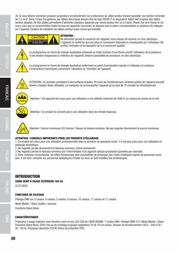
30
DMX
ITALIANOPOLSKI
ESPAÑOLFRANCAIS
DEUTSCHENGLISH
35. Si vous désirez alimenter plusieurs projecteurs simultanément, les conducteurs du câble secteur doivent posséder une section minimale de 1,5 mm². Dans l’Union Européenne, les câbles électriques doivent être de type H05VV-F ou équivalent. Adam Hall propose des câbles secteur adaptés. De tels câbles permettent d’alimenter plusieurs appareils par renvoi secteur de l’un à l’autre, Power Out vers Power In. As-surez-vous que la consommation totale de tous les appareils connectés ne dépasse pas la valeur correspondante en ampères (A) indiquée sur l’appareil. Essayez de maintenir les câbles secteur aussi courts que possible.
ATTENTION :Ne démontez jamais le couvercle de l‘appareil, vous risquez de recevoir un choc électrique. L‘appareil ne renferme aucune pièce ni composant réparable ou remplaçable par l‘utilisateur. Ne confiez l‘entretien et la réparation qu‘à un personnel qualifié.
Le pictogramme en forme de triangle équilatéral contenant un éclair terminé d‘une flèche avertit l‘utilisateur de la présence d‘une tension dangereuse à l‘intérieur de l‘appareil, tension susceptible de provoquer un choc électrique.
Le pictogramme en forme de triangle équilatéral renfermant un point d‘exclamation signale à l‘utilisateur la présence d‘instructions importantes concernant l‘utilisation ou l‘entretien de l‘appareil.
ATTENTION ! Ce symbole correspond à des surfaces chaudes. En cours de fonctionnement, certaines parties de l’appareil peuvent devenir chaudes. Après utilisation, ne manipulez ou ne transportez l’appareil qu’au bout de 10 minutes de refroidissement.
Attention ! Cet appareil est conçu pour une utilisation à une altitude maximale de 2000 m au-dessus du niveau de la mer.
Attention ! Ce produit ne convient pas à une utilisation dans les climats tropicaux.
Attention ! Source lumineuse LED intense ! Risque de lésions oculaires. Ne pas regarder directement la source lumineuse.
ATTENTION ! CONSEILS IMPORTANTS POUR LES PRODUITS D‘ÉCLAIRAGE1. Ce produit est conçu pour une utilisation professionnelle dans le domaine du spectacle vivant : il n‘est pas prévu pour une utilisation en éclairage domestique.2. Ne regardez jamais directement le faisceau lumineux, même brièvement. 3. Ne regardez jamais le faisceau lumineux par l‘intermédiaire d‘un appareil optique grossissant (jumelles par exemple).4. Dans certaines circonstances, les effets Stroboscope sont susceptibles de provoquer des crises d‘épilepsie auprès de personnes sensi-bles. Il est donc conseillé aux personnes épileptiques d‘éviter les lieux où sont installés des stroboscopes.
INTRODUCTIONZOOM ZENIT À USAGE EXTÉRIEUR 180 G2
CLZZ180G2
FONCTIONS DE PILOTAGE
Pilotage DMX sur 3 canaux, 4 canaux, 5 canaux, 9 canaux, 10 canaux, 11 canaux et 17 canaux
Mode Master / Slave (maître / esclave)
Fonctions Stand Alone
CARACTÉRISTIQUES
Projecteur à usage extérieur avec fonction zoom et une LED COB de 180W (RGBW). 7 modes DMX. Pilotage DMX-512. Mode Master / Slave. Fonctions Stand Alone. Étrier fixe ou de montage et goujon adaptateur TV de 16 mm inclus. Tension de fonctionnement 100 V - 240 V CA / 50 - 60 Hz. Puissance absorbée 220 W. Indice de protection IP65.

31
DMX
DEUTSC
HFRAN
CAIS
ESPAÑO
LEN
GLISH
ITALIANO
POLSKI
5
1 2 3 44
7
8
6
Les projecteurs intègrent la technologie standard RDM (Remote Device Management). Ce système de gestion à distance des appareils permet de consulter l'état de fonctionnement et les données de configuration des terminaux RDM via un contrôleur compatible RDM.
RACCORDEMENTS, ÉLÉMENTS DE COMMANDE ET D’AFFICHAGE
1 POWER IN (ENTRÉE D'ALIMENTATION)
Embase d’entrée d’alimentation IP65 Power Twist avec cache étanche en caoutchouc. Tension de fonctionnement 100 - 240 V CA / 50 - 60 Hz. Raccordement à l’aide du câble d’alimentation fourni (mettre systématiquement le cache étanche en caoutchouc si raccord non utilisé).
2 POWER OUT (SORTIE D’ALIMENTATION)
Embase de sortie d’alimentation IP65 Power Twist avec cache étanche en caoutchouc. Permet d'alimenter d'autres projecteurs CAMEO. S’assurer que la consommation totale de tous les appareils connectés ne dépasse pas la valeur en ampères (A) indiquée sur l’appareil (mettre systématiquement le cache étanche en caoutchouc si raccord non utilisé).
3 DMX IN (ENTRÉE DMX)
Embase XLR 5 broches mâle en IP65 permettant de raccorder un contrôleur DMX (par ex. console DMX, mettre systématiquement le cache étanche en caoutchouc si raccord non utilisé).
4 DMX OUT (SORTIE DMX)
Embase XLR 5 broches femelle en IP65 pour le renvoi du signal de commande DMX entrant (mettre systématiquement le cache étanche en caoutchouc si raccord non utilisé).
5 ÉCRAN OLED
Indique le mode de fonctionnement actuel et divers paramètres du système.

32
DMX
ITALIANOPOLSKI
ESPAÑOLFRANCAIS
DEUTSCHENGLISH
6 TOUCHES DE COMMANDE RÉTROÉCLAIRÉES SENSIBLES À LA PRESSION
MODE
Appuyer sur MODE pour accéder au menu de sélection des paramètres du système. Appuyer plusieurs fois sur la touche pour revenir à l’écran principal.
ENTER
Appuyer sur ENTER pour accéder au menu permettant de modifier les valeurs souhaitées, ainsi qu’à l’un des sous-menus. Appuyer également sur ENTER pour valider les modifications apportées.
UP et DOWN
Touches utilisées pour sélectionner les différentes options du menu de sélection (adresse de départ DMX, mode de fonctionnement, etc.) et des sous-menus. Permettent de modifier la valeur d’une option de menu (par ex. adresse de départ DMX) selon les besoins.
7 DISPOSITIF DE COMPENSATION DE PRESSION
Dispositif permettant d’éviter la formation de condensation à l'intérieur de l’appareil. Pour garantir le bon fonctionnement de ce dispositif, il convient de le protéger contre un éventuel encrassement.
8 ŒILLET DE SÉCURITÉ
En cas de montage tête en bas, sécuriser l’appareil via un câble de retenue adapté inséré dans l’œillet prévu à cet effet.
9 VENTILATEUR DE L’APPAREIL
Le ventilateur du boîtier IP65 est placé dans l’unité de refroidissement, entre le système de commande et l’ensemble LED, zoom et lentille. Pour garantir le fonctionnement parfait du ventilateur et la circulation de l'air, ne pas couvrir l'appareil et maintenir les fentes d’aération exemptes d’impuretés.
REMARQUES : Pour garantir une protection des embases DMX contre les projections d’eau, qui soit conforme à la classe de protection IP65, les embases spéciales d’entrée et de sortie DMX doivent être correctement raccordées aux connecteurs XLR spéciaux IP65. Si elles ne sont pas utilisées, mettre en place les caches étanches en caoutchouc fournis. Les embases d’alimentation POWER IN et POWER OUT sont protégées contre les projections d’eau conformément à la classe IP65, à condition d’être correctement raccordées et que les caches étanches en caoutchouc soient utilisés à bon escient.
9
MODE D’EMPLOIREMARQUES
• Si le projecteur est correctement raccordé à l’alimentation secteur, s’affichent alors successivement à l’écran pendant la phase de démarrage les mentions : « Update Wait... » (uniquement à des fins de maintenance), un message de bienvenue (« Welcome to Cameo »), la désignation du modèle et la version du logiciel. En outre, l’unité de zoom est initialisée lors de la phase de démarrage. À l’issue de cette phase, le projecteur est opérationnel et active le mode de fonctionnement précédemment sélectionné.
• Si l'un des modes DMX est activé, et qu'il n'y a pas de signal DMX sur l'entrée DMX, l'écran se met à clignoter après quelques secondes.
• Après env. 30 secondes d’inactivité, l’écran affiche automatiquement le mode de fonctionnement actuellement activé (affichage principal).
• Fonction Fast Access : Pour simplifier la navigation au sein des menus, l’appareil dispose d’une structure de menus intelligente qui permet d’accéder directement aux options de menu et de sous-menu sélectionnées en dernier. 1. Appuyez simultanément sur MODE et sur ENTER pour accéder directement à l'option du sous-menu ouverte en dernier. La valeur correspondante peut alors être instantanément et librement modifiée (concerne l'adresse de départ DMX et tous les modes de fonctionnement). 2. Appuyer sur MODE pour accéder directement à l’option de menu sélectionnée et modifiée en dernier.
• Avant de modifier les paramètres de l’appareil, veiller à ce que l’unité de commande soit à l’abri de l’humidité et de la poussière, qui pourraient entraver son fonctionnement.
• Appuyer sur la touche UP pour faire pivoter les éléments affichés à 180° lorsque l’affichage principal apparaît à l’écran.

33
DMX
DEUTSC
HFRAN
CAIS
ESPAÑO
LEN
GLISH
ITALIANO
POLSKI
RÉGLAGE DE L’ADRESSE DE DÉPART DMX (DMX Address)
Appuyer sur MODE pour accéder au menu de sélection. Sélectionner ensuite l’option de menu « DMX Address » (voir flèche) à l’aide des touches UP et DOWN et appuyer sur ENTER. Sélectionner maintenant l’adresse de départ DMX souhaitée à l’aide des touches UP et DOWN, puis confirmer en appuyant sur ENTER (la valeur maximale dépend du mode de fonctionnement DMX sélectionné). Le mode de fonctionne-ment DMX est alors initialisé et le dernier mode DMX sélectionné est activé.
---------------- Menu ----------------
DMX Address
DMX Mode
Stand Alone
Slave
Settings
System Information
001
5xx- DMX Address
001
RÉGLAGE DU MODE DE FONCTIONNEMENT DMX (mode DMX)
Appuyer sur MODE pour accéder au menu de sélection. Sélectionner ensuite l’option de menu « DMX Mode » (voir flèche) à l’aide des touches UP et DOWN et appuyer sur ENTER. Sélectionner maintenant le mode de fonctionnement DMX souhaité à l’aide des touches UP et DOWN, puis confirmer en appuyant sur ENTER. Les tableaux détaillés des différents modes DMX figurent au chapitre « PILOTAGE EN MODE DMX » de ce manuel.
---------------- Menu ----------------
Adresse de départ DMX
DMX Mode
Stand Alone
Slave
Settings
System Information
------------- DMX Mode -----------
3 CH
4 CH
5 CH
9 CH
10 CH
11 CH
17CH
RÉGLAGE DU MODE DE FONCTIONNEMENT STAND ALONE (Stand Alone)
Appuyer sur MODE pour accéder au menu de sélection des paramètres de l'appareil (--- Menu ---). Utiliser ensuite les touches UP et DOWN pour sélectionner l’option de menu « Stand Alone » (voir flèche), puis confirmer en appuyant sur ENTER. Ce sous-menu permet de sélection-ner les modes de fonctionnement Stand Alone « Auto », « Colour Macro », « Static », « Tunable White » et « User Colour » à l’aide des touches UP et DOWN. Confirmer la sélection en appuyant sur ENTER.
---------------- Menu ----------------
Adresse de départ DMX
DMX Mode
Stand Alone
Slave
Settings
System Information
------------- Stand Alone -----------
Auto
Static
Colour Macro
Tunable White
User Colour
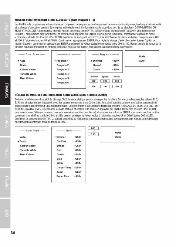
34
DMX
ITALIANOPOLSKI
ESPAÑOLFRANCAIS
DEUTSCHENGLISH
MODE DE FONCTIONNEMENT STAND ALONE AUTO (Auto Program 1 - 6)
Les 6 différents programmes automatiques se composent de séquences de changement de couleur préconfigurées, tandis que la luminosité et la vitesse d'exécution peuvent être réglées individuellement. Conformément à la procédure décrite au chapitre « CONFIGURATION DU MODE STANDALONE », sélectionnez le mode Auto et confirmez avec ENTER. Utiliser ensuite les touches UP et DOWN pour sélectionner l’un des 6 programmes Auto (voir flèche) et confirmer en appuyant sur ENTER. Pour régler la luminosité, sélectionner l’option de menu « Dimmer » à l’aide des touches UP et DOWN, confirmer en appuyant sur ENTER, puis sélectionner la valeur souhaitée, comprise entre 000 et 100, à l’aide des touches UP et DOWN. Confirmer en appuyant sur ENTER. Pour régler la vitesse d’exécution, sélectionner l’option de menu « Speed », confirmer en appuyant sur ENTER, puis régler la valeur souhaitée comprise entre 000 et 100. Régler ensuite la valeur de la fonction zoom en procédant de manière identique. Appuyer sur ENTER pour valider les modifications des valeurs.
Mode
Auto
-------- Stand Alone -------
Auto
Static
Colour Macro
Tunable White
User Colour
----------- Auto -----------
Program 1
Program 2
Program 3
Program 4
Program 5
Program 6
--------- Program x ---------
Dimmer <100>
Speed <100>
Zoom <100>
000
100-
Dimmer Speed
000
100-
RÉGLAGE DU MODE DE FONCTIONNEMENT STAND ALONE MODE STATIQUE (Static)
De façon similaire à un dispositif de pilotage DMX, le mode statique permet de régler les fonctions Dimmer, stroboscope, les valeurs R, G, B, W, etc. directement sur l’appareil, avec des valeurs comprises entre 000 et 255. Il est ainsi possible de créer une scène personnalisée sans recourir à un contrôleur DMX supplémentaire. Conformément à la procédure décrite au chapitre « RÉGLAGE DU MODE DE FONCTION-NEMENT STAND ALONE », sélectionner le mode statique et confirmer la saisie en appuyant sur ENTER. Utilisez les touches UP et DOWN pour sélectionner l'élément du menu que vous souhaitez modifier (voir flèche) et appuyez sur la touche ENTER pour confirmer. Une fenêtre contenant trois chiffres s’affiche à l’écran. Elle permet de régler la valeur voulue à l’aide des touches UP et DOWN (entre 000 et 255). Confirmer en appuyant sur ENTER. La valeurs destinées au réglage de la fonction stroboscope correspondent aux valeurs du stroboscope multifonctions contenues dans les tableaux DMX.
Mode
Static
-------- Stand Alone -------
Auto
Static
Colour Macro
Tunable White
User Colour
----------- Static -----------
Dimmer <255>
DimFine <255>
Strobe <255>
Red <255>
Green <255>
Blue <255>
White <255>
Colour Temp <255>
Zoom <255>
Zoom Fine <255>
000
255-
Zoom
000
100-
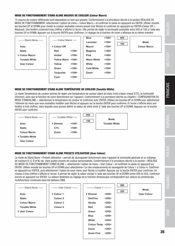
35
DMX
DEUTSC
HFRAN
CAIS
ESPAÑO
LEN
GLISH
ITALIANO
POLSKI
MODE DE FONCTIONNEMENT STAND ALONE MACROS DE COULEUR (Colour Macro)
15 macros de couleur différentes sont disponibles en tant que presets. Conformément à la procédure décrite à la section RÉGLAGE DU MODE DE FONCTIONNEMENT, sélectionner l'option de menu « Colour Macro » et confirmer la saisie en appuyant sur ENTER. Utiliser ensuite les touches UP et DOWN pour choisir la couleur souhaitée comme preset (voir flèche) et confirmer en appuyant sur ENTER (Colour Off = Blackout). Une fenêtre contenant trois chiffres s’affiche à l’écran. Elle permet de régler la luminosité souhaitée entre 000 et 100 à l’aide des touches UP et DOWN. Appuyer sur la touche ENTER pour confirmer. Le réglage de la fonction de zoom s’effectue de la même manière.
Mode
Colour Macro
------- Stand Alone ------
Auto
Static
Colour Macro
Tunable White
User Colour
----- Colour Macro -----
Colour Off
Red <100>
Amber <100>
Yellow Warm <100>
Yellow <100>
Green <100>
Turquoise <100>
Cyan <100>
000
100-
Blue <100>
Lavender <100>
Mauve <100>
Magenta <100>
Pink <100>
Warm White <100>
White <100>
Cold White <100>
Zoom <100>
MODE DE FONCTIONNEMENT STAND ALONE TEMPÉRATURE DE COULEUR (Tunable White)
Le mode Température de couleur permet de régler une température de couleur allant de blanc froid à blanc chaud (CTC), la luminosité (Dimmer), ainsi que la fonction de zoom directement sur l’appareil. Conformément à la procédure décrite au chapitre « CONFIGURATION DU MODE STANDALONE », sélectionnez la température de couleur et confirmez avec ENTER. Utilisez les touches UP et DOWN pour sélectionner l'élément du menu que vous souhaitez modifier (voir flèche) et appuyez sur la touche ENTER pour confirmer. À l'écran s'affiche alors une fenêtre à trois chiffres, dans laquelle vous pouvez définir la valeur de votre choix à l'aide des touches UP et DOWN. Appuyer sur la touche ENTER pour confirmer.
Mode
Tunable White
------- Stand Alone ------
Auto
Static
Colour Macro
Tunable White
User Colour
----- Tunable White -----
Dimmer <100>
CTC <100>
Zoom <100>
000
100-
MODE DE FONCTIONNEMENT STAND ALONE PRESETS UTILISATEUR (User Colour)
Le mode de Stand Alone « Presets utilisateur » permet de sauvegarder directement dans l’appareil la luminosité générale et un mélange de couleurs R, G, B et W, etc. dans quatre presets de couleur personnalisés. Conformément à la procédure décrite à la section « RÉGLAGE DU MODE DE FONCTIONNEMENT STAND ALONE », sélectionner l’option de menu « User Colour » et confirmer la saisie en appuyant sur ENTER. Utiliser ensuite les touches UP et DOWN pour sélectionner l’un des emplacements de sauvegarde de Colour 1 à Colour 4. Confirmer en appuyant sur ENTER, puis sélectionner l’option de sous-menu (voir flèche) à modifier. Appuyer sur la touche ENTER pour confirmer. Un champ à trois chiffres s’affiche à l’écran. Il permet de régler la valeur voulue à l’aide des touches UP et DOWN (entre 000 et 255). Confirmer encore en appuyant sur ENTER. La valeurs destinées au réglage de la fonction stroboscope correspondent aux valeurs du stroboscope multifonctions contenues dans les tableaux DMX.
Mode
User Colour
------- Stand Alone ------
Auto
Static
Colour Macro
Tunable White
User Colour
--------- Colour 1 ---------
Dimmer <255>
DimFine <255>
Strobe <255>
Red <255>
Green <255>
Blue <255>
White <255>
Colour Temp <255>
Zoom <255>
Zoom Fine <255>
000
255-------- User Colour -------
Colour 1
Colour 2
Colour 3
Colour 4

36
DMX
ITALIANOPOLSKI
ESPAÑOLFRANCAIS
DEUTSCHENGLISH
MODE DE FONCTIONNEMENT SLAVE
Appuyer sur MODE pour accéder au menu de sélection. Utiliser ensuite les touches UP et DOWN pour sélectionner l’option de menu « Slave » (voir flèche) et confirmer en appuyant sur ENTER. Relier les unités Slave et Master (même modèle) à l’aide d’un câble DMX. Sur l’unité Master, activer l’un des modes de fonctionnement Stand Alone (Auto, Static, Colour Macro, Tunable White, User Colour). L’unité esclave suit alors l’unité maître. Si aucun signal de commande n'est présent, les caractères se mettent à clignoter sur l'écran, et cessent de clignoter dès qu'un signal de commande est présent.
---------------- Menu ----------------
Adresse de départ DMX
DMX Mode
Stand Alone
Slave
Settings
System Information
Mode
Slave
PARAMÈTRES DE L'APPAREIL (Settings)
Appuyer sur MODE pour accéder au menu de sélection. Utiliser les touches UP et DOWN pour sélectionner l’option de menu « Settings » (voir flèche) et confirmer en appuyant sur ENTER.
---------------- Menu ----------------
Adresse de départ DMX
DMX Mode
Stand Alone
Slave
Settings
System Information
On accède alors au sous-menu permettant de régler les options de sous-menu suivantes (sélectionner en appuyant sur UP et DOWN, confir-mer en appuyant sur ENTER, modifier la valeur ou l’état en appuyant sur UP et DOWN, confirmer en appuyant sur ENTER) :
Settings (en gras = réglage usine)Display Reverse = Rotation de l’affichage On Rotation à 180° des éléments affichés à l’écran (par
ex. en cas de montage tête en bas)Off Pas de rotation de l’affichage
Display Backlight = Éclairage de l’écran et des touches de commande
On Allumé en permanenceOff Désactivation au bout d’env. 30 secondes d’inactivité
DMX Fail = État de fonctionnement en cas d'interruption du signal DMX
Hold Maintien de la dernière commandeBlackout Active la fonction Blackout
Dimmer Curve = Courbe de dimmer Linear L’intensité lumineuse augmente de façon linéaire avec la valeur DMX
Exponential L’intensité lumineuse peut être réglée de façon précise dans la plage de valeurs DMX inférieure et de façon approximative dans la plage de valeurs DMX supérieure
Logarithmic L'intensité lumineuse peut être réglée de façon ap-proximative dans la plage de valeurs DMX inférieure et de façon précise dans la plage de valeurs DMX supérieure
S-Curve L'intensité lumineuse peut être réglée de façon précise dans les plages de valeurs DMX inférieure et supérieure et de façon approximative dans la plage de valeurs DMX moyenne
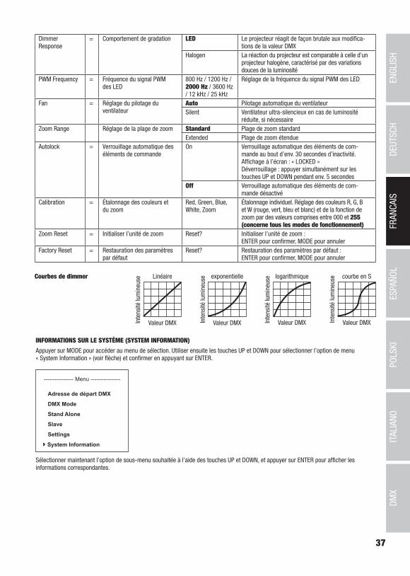
37
DMX
DEUTSC
HFRAN
CAIS
ESPAÑO
LEN
GLISH
ITALIANO
POLSKI
DimmerResponse
= Comportement de gradation LED Le projecteur réagit de façon brutale aux modifica-tions de la valeur DMX
Halogen La réaction du projecteur est comparable à celle d’un projecteur halogène, caractérisé par des variations douces de la luminosité
PWM Frequency = Fréquence du signal PWM des LED
800 Hz / 1200 Hz / 2000 Hz / 3600 Hz / 12 kHz / 25 kHz
Réglage de la fréquence du signal PWM des LED
Fan = Réglage du pilotage du ventilateur
Auto Pilotage automatique du ventilateurSilent Ventilateur ultra-silencieux en cas de luminosité
réduite, si nécessaireZoom Range Réglage de la plage de zoom Standard Plage de zoom standard
Extended Plage de zoom étendueAutolock = Verrouillage automatique des
éléments de commandeOn Verrouillage automatique des éléments de com-
mande au bout d’env. 30 secondes d’inactivité. Affichage à l’écran : « LOCKED » Déverrouillage : appuyer simultanément sur les touches UP et DOWN pendant env. 5 secondes
Off Verrouillage automatique des éléments de com-mande désactivé
Calibration = Étalonnage des couleurs et du zoom
Red, Green, Blue, White, Zoom
Étalonnage individuel. Réglage des couleurs R, G, B et W (rouge, vert, bleu et blanc) et de la fonction de zoom par des valeurs comprises entre 000 et 255 (concerne tous les modes de fonctionnement)
Zoom Reset = Initialiser l’unité de zoom Reset? Initialiser l’unité de zoom : ENTER pour confirmer, MODE pour annuler
Factory Reset = Restauration des paramètres par défaut
Reset? Restauration des paramètres par défaut : ENTER pour confirmer, MODE pour annuler
Linéaire
Valeur DMXInte
nsité
lum
ineu
se exponentielle
Valeur DMXInte
nsité
lum
ineu
se logarithmique
Valeur DMXInte
nsité
lum
ineu
se courbe en S
Valeur DMXInte
nsité
lum
ineu
seCourbes de dimmer
INFORMATIONS SUR LE SYSTÈME (SYSTEM INFORMATION)
Appuyer sur MODE pour accéder au menu de sélection. Utiliser ensuite les touches UP et DOWN pour sélectionner l’option de menu « System Information » (voir flèche) et confirmer en appuyant sur ENTER.
---------------- Menu ----------------
Adresse de départ DMX
DMX Mode
Stand Alone
Slave
Settings
System Information
Sélectionner maintenant l’option de sous-menu souhaitée à l’aide des touches UP et DOWN, et appuyer sur ENTER pour afficher les informations correspondantes.
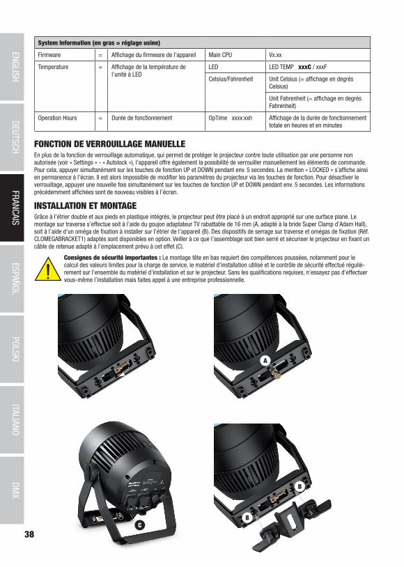
38
DMX
ITALIANOPOLSKI
ESPAÑOLFRANCAIS
DEUTSCHENGLISH
A
B
BC
A
System Information (en gras = réglage usine)
Firmware = Affichage du firmware de l’appareil Main CPU Vx.xx
Temperature = Affichage de la température de l’unité à LED
LED LED TEMP xxxC / xxxF
Celsius/Fahrenheit Unit Celsius (= affichage en degrés Celsius)
Unit Fahrenheit (= affichage en degrés Fahrenheit)
Operation Hours = Durée de fonctionnement OpTime xxxx:xxh Affichage de la durée de fonctionnement totale en heures et en minutes
FONCTION DE VERROUILLAGE MANUELLEEn plus de la fonction de verrouillage automatique, qui permet de protéger le projecteur contre toute utilisation par une personne non autorisée (voir « Settings » - « Autolock »), l’appareil offre également la possibilité de verrouiller manuellement les éléments de commande. Pour cela, appuyer simultanément sur les touches de fonction UP et DOWN pendant env. 5 secondes. La mention « LOCKED » s’affiche ainsi en permanence à l’écran. Il est alors impossible de modifier les paramètres du projecteur via les touches de fonction. Pour désactiver le verrouillage, appuyer une nouvelle fois simultanément sur les touches de fonction UP et DOWN pendant env. 5 secondes. Les informations précédemment affichées sont de nouveau visibles à l’écran.
INSTALLATION ET MONTAGEGrâce à l’étrier double et aux pieds en plastique intégrés, le projecteur peut être placé à un endroit approprié sur une surface plane. Le montage sur traverse s’effectue soit à l’aide du goujon adaptateur TV rabattable de 16 mm (A, adapté à la bride Super Clamp d’Adam Hall), soit à l’aide d’un oméga de fixation à installer sur l’étrier de l’appareil (B). Des dispositifs de serrage sur traverse et omégas de fixation (Réf. CLOMEGABRACKET1) adaptés sont disponibles en option. Veiller à ce que l’assemblage soit bien serré et sécuriser le projecteur en fixant un câble de retenue adapté à l’emplacement prévu à cet effet (C).
Consignes de sécurité importantes : Le montage tête en bas requiert des compétences poussées, notamment pour le calcul des valeurs limites pour la charge de service, le matériel d’installation utilisé et le contrôle de sécurité effectué réguliè-rement sur l’ensemble du matériel d’installation et sur le projecteur. Sans les qualifications requises, n'essayez pas d’effectuer vous-même l’installation mais faites appel à une entreprise professionnelle.

39
DMX
DEUTSC
HFRAN
CAIS
ESPAÑO
LEN
GLISH
ITALIANO
POLSKI
TECHNIQUE DMX
DMX-512Le terme DMX (Digital Multiplex) désigne un protocole de transport universel permettant la communication entre des appareils et des contrôleurs à ce format. Un contrôleur DMX envoie des données DMX aux appareils DMX qui lui sont connectés. Les données DMX sont transportées sous forme d'un flux série, renvoyé d'un appareil au suivant via des connecteurs XLR repérés "DMX IN" et "DMX OUT". Le nombre total d'appareils ainsi connectés ne doit pas dépasser 32. Le dernier appareil de la chaîne doit posséder une résistance de terminaison (Terminator).
PROTOCOLE DMXIl s'agit d'un langage universel, permettant d'interconnecter des appareils DMX de type différents, de marques différentes, et de tous les piloter depuis un contrôleur DMX central. Pour un transport optimal des données, il est recommandé d'utiliser les câbles les plus courts possibles pour interconnecter les appareils. L'ordre dans lequel les différents appareils sont connectés au sein d'un réseau DMS n'a aucune influence sur l'adressage. Autrement dit, vous pouvez placer l'appareil possédant l'adresse DMX 1 où vous le désirez dans la chaîne DMX : au début, à la fin, au milieu... Si un appareil s'est vu affecter l'adresse DMX 1, le contrôleur "sait" qu'il doit lui envoyer toutes les données destinées à l'adresse 1, quelle que soit la position dudit appareil dans la chaîne DMX.
CONNEXION EN SÉRIE DE PLUSIEURS PROJECTEURS1. Reliez la fiche XLR mâle (3 ou 5 points) du câble DMX à la sortie DMX (embase XLR femelle) du premier appareil DMX (par exemple, un contrôleur DMX).2. Reliez le connecteur XLR femelle du câble DMX relié au premier projecteur à l'entrée DMX (connecteur XLR mâle) de l'appareil DMX suivant. Reliez la sortie DMX de cet appareil, selon le même méthode, à l'entrée DMX de l'appareil DMX suivant, et ainsi de suite. Veillez à ce que tous les appareils DMX soient reliés en série, et n'oubliez pas que les liaisons ne peuvent être partagées sans utiliser de splitter actif. Ne pas dépasser le nombre maximal d'appareils par chaîne DMX, soit 32.
Vous trouverez un choix complet de câbles compatibles DMX dans les gammes Adam Hall 3 STAR, 4 STAR et 5 STAR.Si vous fabriquez vous-mêmes vos câbles, respectez les modalités de câblage DMX. En particulier : Ne reliez jamais le blindage du câble à la masse du connecteur, et vérifiez bien qu'en aucun cas le blindage du câble n'entre en contact avec le corps du connecteur XLR. Si le blindage entre en contact avec la masse, cela peut provoquer des courts-circuits et des défaillances système.
Assignation des contactsCâble DMX avec connecteurs XLR 3 points : Câble DMX avec connecteurs XLR 5 points (les points 4 et 5 ne sont pas câblés):
Shield
23
1
23
1
123
45
12
34
5
Shield
Pour éviter tout dysfonctionnement, le dernier appareil d'une chaîne DMX doit être équipé d'une résistance de terminaison (120 Ohms, 1/4 Watt).Connecteur XLR 3 points avec résistance de terminaison : K3DMXT3Connecteur XLR 5 points avec résistance de terminaison : K3DMXT5
Assignation des contactsConnecteur XLR 3 points Connecteur XLR 5 points
23
1
12
34
5
Pour utiliser des appareils DMX munis de connecteurs 3 points avec des appareils DMX munis de connecteurs 5 points, il faut utiliser un adaptateur.
Assignation des contactsAdaptateur XLR 5 points mâle vers XLR 3 points femelle K3DGF0020Les points 4 et 5 ne sont pas connectés.
Assignation des contactsAdaptateur XLR 3 points mâle vers XLR 5 points femelle K3DHM0020Les points 4 et 5 ne sont pas connectés.
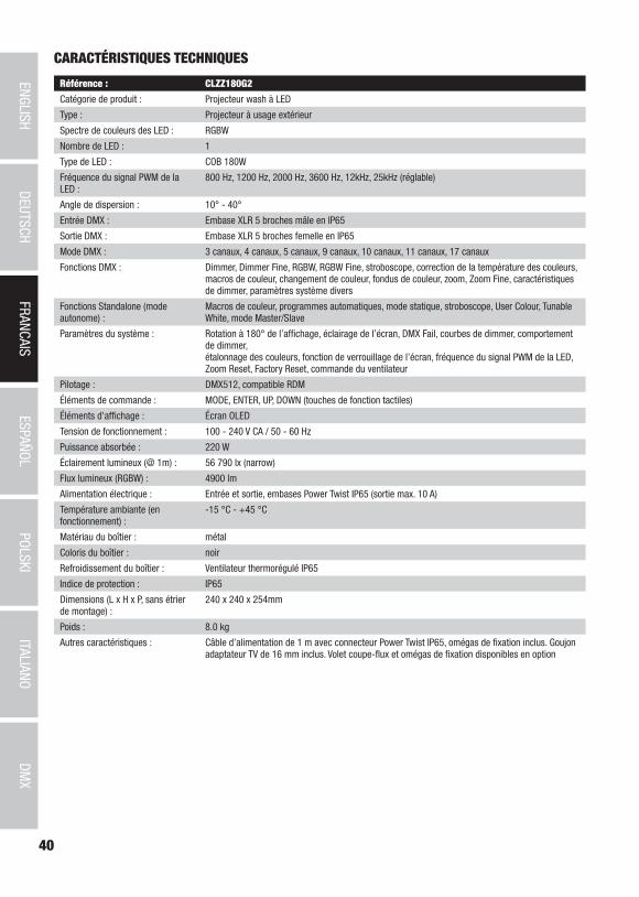
40
DMX
ITALIANOPOLSKI
ESPAÑOLFRANCAIS
DEUTSCHENGLISH
Référence : CLZZ180G2
Catégorie de produit : Projecteur wash à LED
Type : Projecteur à usage extérieur
Spectre de couleurs des LED : RGBW
Nombre de LED : 1
Type de LED : COB 180W
Fréquence du signal PWM de la LED :
800 Hz, 1200 Hz, 2000 Hz, 3600 Hz, 12kHz, 25kHz (réglable)
Angle de dispersion : 10° - 40°
Entrée DMX : Embase XLR 5 broches mâle en IP65
Sortie DMX : Embase XLR 5 broches femelle en IP65
Mode DMX : 3 canaux, 4 canaux, 5 canaux, 9 canaux, 10 canaux, 11 canaux, 17 canaux
Fonctions DMX : Dimmer, Dimmer Fine, RGBW, RGBW Fine, stroboscope, correction de la température des couleurs, macros de couleur, changement de couleur, fondus de couleur, zoom, Zoom Fine, caractéristiques de dimmer, paramètres système divers
Fonctions Standalone (mode autonome) :
Macros de couleur, programmes automatiques, mode statique, stroboscope, User Colour, Tunable White, mode Master/Slave
Paramètres du système : Rotation à 180° de l’affichage, éclairage de l’écran, DMX Fail, courbes de dimmer, comportement de dimmer, étalonnage des couleurs, fonction de verrouillage de l’écran, fréquence du signal PWM de la LED, Zoom Reset, Factory Reset, commande du ventilateur
Pilotage : DMX512, compatible RDM
Éléments de commande : MODE, ENTER, UP, DOWN (touches de fonction tactiles)
Éléments d'affichage : Écran OLED
Tension de fonctionnement : 100 - 240 V CA / 50 - 60 Hz
Puissance absorbée : 220 W
Éclairement lumineux (@ 1m) : 56 790 lx (narrow)
Flux lumineux (RGBW) : 4900 lm
Alimentation électrique : Entrée et sortie, embases Power Twist IP65 (sortie max. 10 A)
Température ambiante (en fonctionnement) :
-15 °C - +45 °C
Matériau du boîtier : métal
Coloris du boîtier : noir
Refroidissement du boîtier : Ventilateur thermorégulé IP65
Indice de protection : IP65
Dimensions (L x H x P, sans étrier de montage) :
240 x 240 x 254mm
Poids : 8.0 kg
Autres caractéristiques : Câble d’alimentation de 1 m avec connecteur Power Twist IP65, omégas de fixation inclus. Goujon adaptateur TV de 16 mm inclus. Volet coupe-flux et omégas de fixation disponibles en option
CARACTÉRISTIQUES TECHNIQUES

41
DMX
DEUTSC
HFRAN
CAIS
ESPAÑO
LEN
GLISH
ITALIANO
POLSKI
DECLARATIONS
GARANTIE FABRICANT & LIMITATION DE RESPONSABILITÉ Nos conditions actuelles de garantie et de limitation de responsabilité sont disponibles à l‘adresse suivante : https://cdn-shop.adamhall.com/media/pdf/MANUFACTURERS-DECLARATIONS_CAMEO.pdf. Pour les réparations, veuillez contacter Adam Hall GmbH, Adam-Hall-Str. 1, 61267 Neu Anspach / E-Mail [email protected] / +49 (0)6081 / 9419-0.
TRI ET MISE AUX DÉCHETS CORRECTE DE CE PRODUIT (Valid in the European Union and other European countries with waste separation) (Applicable dans l‘Union Européenne et les autres pays européens pratiquant le tri des déchets) La présence de ce symbole sur le
produit ou sur la documentation correspondante indique qu‘en fin de vie, le produit ne doit pas être jeté avec les déchets normaux, afin d‘éviter tout dommage à l‘environnement ou aux personnes consécutive à une élimination non contrôlée des déchets. Séparez-le des aut-res types de déchets et recyclez-le, afin de promouvoir la réutilisation durable des ressources naturelles. Nous conseillons aux utilisateurs non professionnels de contacter le revendeur chez qui ils ont acheté le produit, ou un représentant gouvernemental local, pour plus de
Conformité CELa société Adam Hall GmbH déclare par la présente que ce produit est compatible avec les régulations suivantes (le cas échéant) :R&TTE (1999/5/EG) et RED (2014/53/EU) à partir de juin 2017Directive basse tension (2014/35/EU)Directive CEM (2014/30/EU)RoHS (2011/65/EU)La Déclaration de Conformité complète est disponible sur le site Web www.adamhall.com. Pour toute information complémentaire, contactez-nous : [email protected].
détails sur le lieu de collecte et la façon de recycler cet appareil dans le meilleur respect de l‘environnement possible.. Nous invitons les utilisateurs professionnels à contacter leur fournisseur et à vérifier les termes et conditions de leur contrat d‘achat. Ce produit ne doit pas être mélangé à d‘autres déchets commerciaux lors de la collecte.

42
DMX
ITALIANOPOLSKI
ESPAÑOLFRANCAIS
DEUTSCHENGLISH
ESPAÑOL
¡GRACIAS POR ELEGIR CAMEO LIGHT!Este equipo está diseñado y fabricado con los estándares de calidad más exigentes, para garantizar un correcto funcionamiento durante muchos años.Lea atentamente este manual de usuario para poder aprovechar rápidamente toda la funcionalidad de su nuevo producto de Cameo Light. Más información sobre Cameo Light en la web WWW.CAMEOLIGHT.COM.
MEDIDAS DE SEGURIDAD 1. Lea atentamente las instrucciones de este manual. 2. Guarde toda la información en un lugar seguro para futuras consultas. 3. Siga las instrucciones indicadas. 4. Siga todas las advertencias. No quite las instrucciones de seguridad ni cualquier otra información indicada en el equipo. 5. Utilice el equipo únicamente según la finalidad prevista. 6. Utilice solo soportes y fijaciones que sean robustos y adecuados cuando instale el equipo en instalaciones fijas. Asegúrese de que los soportes de pared están correctamente instalados y firmemente fijados. Asegúrese de que el equipo está sólidamente instalado y no se puede caer. 7. Al instalar el equipo, respete las normas de seguridad aplicables en su país. 8. Evite instalar el equipo cerca de radiadores, acumuladores de calor, estufas o cualquier otra fuente de calor. Asegúrese de que el equipo esté instalado en un lugar con ventilación suficiente para evitar cualquier sobrecalentamiento. 9. No coloque sobre el equipo fuentes de llamas sin protección, por ejemplo, velas encendidas. 10. Evite bloquear las rejillas de ventilación. 11. El equipo está diseñado para uso en interiores; no lo utilice cerca del agua (excepto los equipos específicamente diseñados para uso en exterior, en cuyo caso tenga en cuenta las indicaciones mencionadas a continuación). No exponga este equipo a materiales, líquidos o gases inflamables. 12. Evite exponer el equipo a gotas o salpicaduras que puedan caer dentro del mismo. No coloque recipientes llenos de líquido, como floreros o vasos, sobre el equipo. 13. Asegúrese de no dejar caer ningún objeto dentro del equipo. 14. Emplee el equipo únicamente con los accesorios recomendados por el fabricante. 15. No abra el equipo ni intente modificarlo. 16. Una vez conectado el equipo, compruebe que en toda la longitud del cableado no hay peligro de que provoque una caída, por ejemplo. 17. Durante el transporte, asegúrese de que el equipo no se caiga y pueda causar daños personales o materiales.18. Si el equipo no funciona correctamente, o si se ha vertido líquido sobre él, o si un objeto ha caído en su interior o si ha sufrido algún desperfecto, apague inmediatamente el equipo y desenchufe el cable eléctrico (si se trata de un equipo activo). Únicamente un técnico especialista debe reparar el equipo. 19. Para limpiar el equipo utilice un paño seco. 20. Procure seguir las normas vigentes en su país sobre reciclaje de desechos. Separe los componentes de plástico, papel y cartón del paquete para reciclarlos en sus contenedores respectivos. 21. No deje las bolsas de plástico al alcance de los niños.
PARA LOS EQUIPOS CON TOMA ELÉCTRICA:22. ADVERTENCIA: Si el cable eléctrico está provisto de un contacto de protección, debe conectarse a una toma eléctrica con conexión a tierra. No desactivar nunca esta conexión de protección a tierra del cable eléctrico. 23. Si el equipo ha estado expuesto a un cambio brusco de temperatura (por ejemplo, después del transporte), no lo encienda inmediata-mente. La condensación o la humedad podrían dañar el equipo. Deje que el equipo alcance la temperatura ambiente antes de encenderlo. 24. Antes de conectar el cable eléctrico a la toma de corriente, compruebe si la tensión y la frecuencia del suministro eléctrico coinciden con las especificaciones de este equipo. Si el equipo dispone de un selector de tensión, antes de enchufarlo a la red eléctrica, asegúrese de que el valor seleccionado coincide con la tensión de suministro. Si el enchufe o el adaptador de corriente no encajan en la toma eléctrica, consulte a un electricista. 25. Asegúrese de que el cable eléctrico no está pinzado. Evite que el cable resulte pellizcado, sobre todo en los extremos de conexión al equipo y en la toma eléctrica. 26. Al conectar el equipo, asegúrese de que el cable eléctrico o el adaptador de corriente estén siempre accesibles. Desconecte el equipo de la toma de corriente cuando no esté en uso o antes de limpiarlo. Para ello, desconecte el cable eléctrico y el adaptador de corriente del conector del equipo en vez de desenchufar el cable de la toma eléctrica. No tocar el cable eléctrico ni el adaptador de corriente con las manos húmedas. 27. No encienda y apague el equipo en cortos intervalos de tiempo, ya que se reduce así la vida útil del sistema.28. NOTA IMPORTANTE: Sustituya los fusibles únicamente por otros del mismo tipo y de las mismas características. Si el fusible se funde continuamente, póngase en contacto con un servicio técnico autorizado. 29. Para desconectar completamente el equipo de la tensión eléctrica, desenchufe el cable eléctrico o el adaptador de corriente de la toma eléctrica. 30. Si el equipo dispone de un enchufe eléctrico Volex, deberá desbloquearse el Volex del equipo para desenchufarlo. Esto implica que un tirón en el cable eléctrico puede desplazar el equipo y provocar daños personales o materiales. Por tanto, asegúrese de instalar los cables con sumo cuidado. 31. Si es probable que caiga un rayo por una tormenta eléctrica o si no va a emplear el equipo durante mucho tiempo, desenchufe el cable eléctrico y el adaptador de corriente.32. Al montar el equipo, asegúrese de que no está alimentado eléctricamente (el enchufe no debe estar conectado a la red eléctrica).33. La acumulación de polvo y otras partículas en el interior del equipo puede causar daños. Dependiendo de las condiciones ambientales (polvo, nicotina, niebla, etc.), deberá realizarse periódicamente el mantenimiento o la limpieza del equipo por personal especializado, para evitar cualquier sobrecalentamiento o fallo de funcionamiento (mantenimiento y limpieza no cubiertos por la garantía).

43
DMX
DEUTSC
HFRAN
CAIS
ESPAÑO
LEN
GLISH
ITALIANO
POLSKI
34. Asimismo, deberá dejarse una distancia mínima de 0,5 metros con cualquier material inflamable.35. Los cables eléctricos que sirven para alimentar a varios equipos deben tener una sección mínima de 1,5 mm². En la Unión Europa debe emplearse un cable de tipo H05VV-F, o similar. Adam Hall dispone de cables adecuados. Con estos cables podrá alimentar eléctricamente varios equipos conectando el enchufe de salida POWER OUT de un equipo al de entrada POWER IN de otro equipo. Asegúrese de que el consumo total de todos los equipos conectados no supere los amperios especificados del equipo (serigrafiado en el equipo). Además, procu-re que las tiradas de cable sean lo más cortas posible.
ATENCIÓN:Para evitar el riesgo de descarga eléctrica, no retire la tapa. El equipo no contiene elementos que el usuario pueda reparar o sustituir. Para cualquier tarea de mantenimiento o reparación, acuda a un técnico cualificado.
El símbolo de rayo dentro de un triángulo equilátero advierte al usuario de la presencia de tensiones peligrosas sin aislamiento dentro del equipo que pueden causar una descarga eléctrica.
El símbolo de exclamación dentro de un triángulo equilátero advierte al usuario de la existencia de importantes instrucciones de uso y mantenimiento.
ATTENTION ! Ce symbole correspond à des surfaces chaudes. En cours de fonctionnement, certaines parties de l’appareil peuvent devenir chaudes. Après utilisation, ne manipulez ou ne transportez l’appareil qu’au bout de 10 minutes de refroidissement.
¡Advertencia! Este equipo está diseñado para ser utilizado a una altura que no supere los 2000 metros sobre el nivel del mar.
¡Advertencia! Este equipo no está diseñado para funcionar en climas tropicales.
Precaución. Fuente de luz LED intensiva. Peligro de lesiones oculares. No mirar directamente la fuente de luz.
¡ATENCIÓN: INFORMACIÓN IMPORTANTE SOBRE LOS PRODUCTOS DE ILUMINACIÓN!1. Este producto ha sido desarrollado para uso profesional en el sector de eventos y no está diseñado para la iluminación doméstica.2. No mire directamente el haz de luz, ni siquiera momentáneamente. 3. No mire directamente el haz de luz con instrumentos ópticos, como lentes de aumento.4. ¡Los efectos estroboscópicos pueden a veces causar convulsiones en personas fotosensibles! Las personas con epilepsia deben evitar los lugares en los que se usan luces estroboscópicas.
INTRODUCCIÓNFOCO ZENIT ZOOM 180 G2 PARA EXTERIORES
CLZZ180G2
MODOS DE CONTROL
Control DMX de 3 canales, 4 canales, 5 canales, 9 canales, 10 canales, 11 canales y 17 canales
Modo maestro/esclavo
Funciones autónomas
CARACTERÍSTICAS
Foco con función de zoom para exteriores y un LED COB (RGBW) de 180W Siete modos DMX Control DMX 512. Modo maestro/esclavo Funciones autónomas Soporte de apoyo o de montaje y adaptador de espiga de 16 mm incluido Tensión de servicio: 100 V - 240 V CA / 50 - 60 Hz Consumo de potencia 220 W Clase de protección IP65.
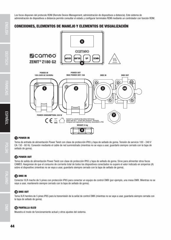
44
DMX
ITALIANOPOLSKI
ESPAÑOLFRANCAIS
DEUTSCHENGLISH
5
1 2 3 44
7
8
6
Los focos disponen del protocolo RDM (Remote Device Management, administración de dispositivos a distancia). Este sistema de administración de dispositivos a distancia permite consultar el estado y configurar terminales RDM mediante un controlador con función RDM.
CONEXIONES, ELEMENTOS DE MANEJO Y ELEMENTOS DE VISUALIZACIÓN
1 POWER IN
Toma de entrada de alimentación Power Twist con clase de protección IP65 y tapa de sellado de goma. Tensión de servicio 100 - 240 V CA / 50 - 60 Hz. Conexión mediante el cable de red suministrado (mientras no se vaya a usar, guardarlo siempre cerrado con la tapa de sellado de goma).
2 POWER OUT
Toma de salida de alimentación Power Twist con clase de protección IP65 y tapa de sellado de goma. Sirve para alimentar otros focos CAMEO. Asegúrese de que el consumo de corriente total de todos los dispositivos conectados no supere el valor indicado en amperios (A) sobre el dispositivo (mientras no se vaya a usar, guardarlo siempre cerrado con la tapa de sellado de goma).
3 DMX IN
Conector XLR macho de 5 pines con protección IP65 para conectar un equipo de control DMX (por ejemplo, una mesa DMX. Mientras no se vaya a usar, mantenerlo siempre cerrado con la tapa de sellado de goma).
4 DMX OUT
Toma XLR hembra de 5 pines IP65 para la transmisión de la señal de control DMX (mientras no se vaya a usar, guardarla siempre cerrada con la tapa de sellado de goma).
5 PANTALLA OLED
Muestra el modo de funcionamiento actual y otros ajustes del sistema.

45
DMX
DEUTSC
HFRAN
CAIS
ESPAÑO
LEN
GLISH
ITALIANO
POLSKI
6 BOTONES TÁCTILES CON RETROILUMINACIÓN
MODE
Pulsando MODE accederá al menú de selección para la configuración del sistema. Pulsando repetidas veces este botón se regresa a la pantalla principal.
ENTER
Pulsando ENTER accederá al nivel del menú en el que podrá modificar valores y acceder a un submenú. Para confirmar la modificación de los valores, pulse de nuevo ENTER.
UP y DOWN
Selección de las opciones de menú individuales dentro del menú de selección (dirección DMX, modo operativo, etc.) y de los submenús. Permiten modificar el valor de una opción del menú según se desee, por ejemplo, la dirección DMX.
7 ELEMENTO COMPENSADOR DE PRESIÓN
Elemento compensador de presión para evitar la formación de condensación en el interior de la carcasa. Para garantizar un rendimiento perfecto de esta función, deberá evitarse que el elemento se ensucie.
8 CÁNCAMO DE SEGURIDAD
En trabajos de montaje en altura, fije el equipo con un cable de seguridad adecuado al cáncamo de seguridad.
9 VENTILADOR DE LA CARCASA
El ventilador de la carcasa con clase de protección IP65 se encuentra en la unidad de refrigeración, entre la unidad de control y la unidad con LED, zoom y lente. Para garantizar el perfecto funcionamiento del ventilador y de la circulación del aire, no cubra el aparato y mantenga las ranuras de ventilación limpias sin suciedad.
NOTAS: Para garantizar la protección contra salpicaduras de los conectores DMX conforme a la clase de protección IP65, las tomas de entrada y salida DMX especiales deberán quedar bien cerradas con los conectores XLR especiales con clase de protección IP65 o utilizar las tapas de sellado de goma para su cierre. Los conectores de red POWER IN y POWER OUT estarán protegidos contra salpicaduras conforme a la clase de protec-ción IP65 tanto si se conectan debidamente como si se hace un uso correcto de las tapas de sellado de goma.
9
FUNCIONAMIENTOOBSERVACIONES
• En cuanto el foco esté correctamente conectado a la red eléctrica, durante el proceso de arranque se mostrarán de forma consecutiva en pantalla los mensajes «Update Wait...» (Actualización del software, espere) (solo con fines de servicio técnico) y «Welcome to Cameo» (Bienvenidos a Cameo), así como la denominación del modelo y de la versión del software. Además, la unidad de zoom se inicializa durante el procedimiento de arranque. Tras este procedimiento, el foco estará listo para funcionar y se activará en el último modo operativo que se haya seleccionado.
• Si está activado uno de los modos operativos DMX y no hay una señal DMX en la entrada DMX, la pantalla comenzará a parpadear después de algunos segundos.
• Tras unos 30 segundos sin actividad, en la pantalla se muestra automáticamente el modo operativo que esté activado en ese momento (pantalla principal).
• Función Fast Access: Para facilitar la navegación del menú, el dispositivo dispone de una estructura de menú inteligente que permite acceder directamente a las últimas opciones de menú y opciones de submenú que se hayan seleccionado. 1. Pulsando a la vez MODE y ENTER accederá directamente a la última opción de submenú que se haya editado y podrá modificar inmediatamente el valor correspon-diente a su gusto (la dirección de inicio DMX y todos los modos operativos). 2. Pulsando MODE se accede directamente a la última opción del menú que se hubiese seleccionado y editado.
• Antes de modificar los parámetros de configuración del dispositivo, asegúrese de que la unidad de mando esté seca y sin polvo con el fin de que su funcionalidad no se vea afectada.
• La imagen en pantalla podrá girarse 180° pulsando UP cuando se visualice la pantalla principal.

46
DMX
ITALIANOPOLSKI
ESPAÑOLFRANCAIS
DEUTSCHENGLISH
CONFIGURACIÓN DE LA DIRECCIÓN INICIAL DMX (dirección DMX)
Pulsando MODE accederá al menú de selección. Seleccione ahora la opción de menú «DMX Address» (indicada por la flecha) con los boto-nes UP y DOWN, y pulse ENTER. Ahora, seleccione la dirección inicial DMX deseada pulsando de nuevo los botones UP y DOWN, y confirme la selección con ENTER (el valor más alto dependerá del modo DMX que esté activado en ese momento). Se inicia el modo operativo DMX y se activa el último modo DMX seleccionado.
---------------- Menu ----------------
DMX Address
DMX Mode
Stand Alone
Slave
Settings
Información del sistema
001
5xx- DMX Address
001
AJUSTE DEL MODO DMX (DMX Mode)
Pulsando MODE accederá al menú de selección. Seleccione ahora la opción de menú «DMX Mode» (indicada por la flecha) con los botones UP y DOWN, y pulse ENTER. El modo DMX deseado se selecciona nuevamente con los botones UP y DOWN, y se confirma con ENTER. Podrá encontrar tablas DMX detalladas en la sección «CONTROL DMX» de este manual.
---------------- Menu ----------------
DMX Address
DMX Mode
Stand Alone
Slave
Settings
Información del sistema
------------- Modo DMX -----------
3 CH
4 CH
5 CH
9 CH
10 CH
11 CH
17CH
CONFIGURAR MODO OPERATIVO AUTÓNOMO (Stand Alone)
Pulsando MODE accederá al menú de selección para la configuración del dispositivo (--- Menu ---). Ahora, utilice los botones UP y DOWN para seleccionar la opción de menú «Stand Alone» (indicada por la flecha) y confirme la selección con ENTER. A continuación, en el submenú puede seleccionar con los botones UP y DOWN cualquiera de los modos operativos autónomos: «Auto», «Colour Macro», «Static», «Tunable White» o «User Color». Confirme la selección con ENTER.
---------------- Menu ----------------
DMX Address
DMX Mode
Stand Alone
Slave
Settings
Información del sistema
------------- Autónomo -----------
Auto
Static
Colour Macro
Tunable White
User Colour
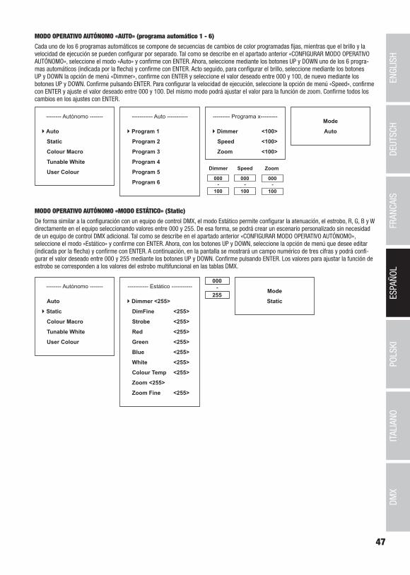
47
DMX
DEUTSC
HFRAN
CAIS
ESPAÑO
LEN
GLISH
ITALIANO
POLSKI
MODO OPERATIVO AUTÓNOMO «AUTO» (programa automático 1 - 6)
Cada uno de los 6 programas automáticos se compone de secuencias de cambios de color programadas fijas, mientras que el brillo y la velocidad de ejecución se pueden configurar por separado. Tal como se describe en el apartado anterior «CONFIGURAR MODO OPERATIVO AUTÓNOMO», seleccione el modo «Auto» y confirme con ENTER. Ahora, seleccione mediante los botones UP y DOWN uno de los 6 progra-mas automáticos (indicada por la flecha) y confirme con ENTER. Acto seguido, para configurar el brillo, seleccione mediante los botones UP y DOWN la opción de menú «Dimmer», confirme con ENTER y seleccione el valor deseado entre 000 y 100, de nuevo mediante los botones UP y DOWN. Confirme pulsando ENTER. Para configurar la velocidad de ejecución, seleccione la opción de menú «Speed», confirme con ENTER y ajuste el valor deseado entre 000 y 100. Del mismo modo podrá ajustar el valor para la función de zoom. Confirme todos los cambios en los ajustes con ENTER.
Mode
Auto
-------- Autónomo -------
Auto
Static
Colour Macro
Tunable White
User Colour
----------- Auto -----------
Program 1
Program 2
Program 3
Program 4
Program 5
Program 6
--------- Programa x---------
Dimmer <100>
Speed <100>
Zoom <100>
000
100-
Dimmer Speed
000
100-
MODO OPERATIVO AUTÓNOMO «MODO ESTÁTICO» (Static)
De forma similar a la configuración con un equipo de control DMX, el modo Estático permite configurar la atenuación, el estrobo, R, G, B y W directamente en el equipo seleccionando valores entre 000 y 255. De esa forma, se podrá crear un escenario personalizado sin necesidad de un equipo de control DMX adicional. Tal como se describe en el apartado anterior «CONFIGURAR MODO OPERATIVO AUTÓNOMO», seleccione el modo «Estático» y confirme con ENTER. Ahora, con los botones UP y DOWN, seleccione la opción de menú que desee editar (indicada por la flecha) y confirme con ENTER. A continuación, en la pantalla se mostrará un campo numérico de tres cifras y podrá confi-gurar el valor deseado entre 000 y 255 mediante los botones UP y DOWN. Confirme pulsando ENTER. Los valores para ajustar la función de estrobo se corresponden a los valores del estrobo multifuncional en las tablas DMX.
Mode
Static
-------- Autónomo -------
Auto
Static
Colour Macro
Tunable White
User Colour
----------- Estático -----------
Dimmer <255>
DimFine <255>
Strobe <255>
Red <255>
Green <255>
Blue <255>
White <255>
Colour Temp <255>
Zoom <255>
Zoom Fine <255>
000
255-
Zoom
000
100-

48
DMX
ITALIANOPOLSKI
ESPAÑOLFRANCAIS
DEUTSCHENGLISH
MODO OPERATIVO AUTÓNOMO «MACROS DE COLOR» (Colour Macro)
Están disponibles 15 macros de color como preajustes. Tal como se describe en el apartado anterior «CONFIGURAR MODO OPERATIVO», seleccione la opción del menú «Colour Macro» y confirme con ENTER. Ahora, con los botones UP y DOWN, seleccione el color deseado como preset (indicado por la flecha) y confirme con ENTER (Colour Off = completamente apagado). A continuación, en la pantalla se mostrará un campo numérico de tres cifras y podrá configurar el brillo deseado entre 000 y 100 mediante los botones UP y DOWN. Confirme pulsando ENTER. El ajuste de la función de zoom se efectúa de la misma manera.
Mode
Colour Macro
------- Autónomo ------
Auto
Static
Colour Macro
Tunable White
User Colour
----- Macro de color -----
Colour Off
Red <100>
Amber <100>
Yellow Warm <100>
Yellow <100>
Green <100>
Turquoise <100>
Cyan <100>
000
100-
Blue <100>
Lavender <100>
Mauve <100>
Magenta <100>
Pink <100>
Warm White <100>
White <100>
Cold White <100>
Zoom <100>
MODO OPERATIVO AUTÓNOMO «TEMPERATURA DE COLOR» (Tunable White)
El modo «Temperatura de color» permite ajustar la luz directamente en el equipo con una temperatura de color que va del blanco frío al blanco cálido (CTC), el brillo (Dimmer) y la función de zoom. Tal como se describe en el apartado anterior «CONFIGURAR MODO OPERATIVO AUTÓNOMO», seleccione el modo «Temperatura de color» y confirme con ENTER. Ahora, con los botones UP y DOWN, seleccione la opción de menú que desee editar (indicada por la flecha) y confirme con ENTER. A continuación, en la pantalla se mostrará un campo numérico de tres cifras y podrá configurar el valor deseado mediante los botones UP y DOWN. Confirme pulsando ENTER.
Mode
Tunable White
------- Autónomo ------
Auto
Static
Colour Macro
Tunable White
User Colour
----- Tunable White -----
Dimmer <100>
CTC <100>
Zoom <100>
000
100-
MODO OPERATIVO AUTÓNOMO «PRESETS DEL USUARIO» (User Colour)
El modo operativo «Presets del usuario» permite guardar directamente en el equipo el brillo general y una mezcla de colores entre R, G, B y W en cuatro presets de colores individuales. Tal como se describe en el apartado anterior «CONFIGURAR MODO OPERATIVO AUTÓNOMO», seleccione la opción de menú «User Colour» y confirme con ENTER. Ahora, seleccione una de las posiciones de memoria Color 1 a Color 4 mediante los botones UP y DOWN, confirme con ENTER y seleccione la opción de submenú que quiera editar (indicada por la flecha). Confir-me pulsando ENTER. A continuación, en la pantalla se mostrará un campo numérico de tres cifras y podrá configurar el valor deseado entre 000 y 255 mediante los botones UP y DOWN. Vuelva a confirmar con ENTER. Los valores para ajustar la función de estrobo se corresponden a los valores del estrobo multifuncional en las tablas DMX
Mode
User Colour
------- Autónomo ------
Auto
Static
Colour Macro
Tunable White
User Colour
--------- Color 1 ---------
Dimmer <255>
DimFine <255>
Strobe <255>
Red <255>
Green <255>
Blue <255>
White <255>
Colour Temp <255>
Zoom <255>
Zoom Fine <255>
000
255-------- Color de usuario
-------
Colour 1
Colour 2
Colour 3
Colour 4
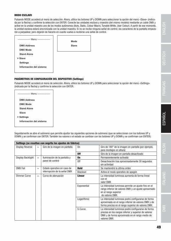
49
DMX
DEUTSC
HFRAN
CAIS
ESPAÑO
LEN
GLISH
ITALIANO
POLSKI
MODO ESCLAVO
Pulsando MODE accederá al menú de selección. Ahora, utilice los botones UP y DOWN para seleccionar la opción del menú «Slave» (indica-da por la flecha) y confirme la selección con ENTER. Conecte las unidades esclava y maestra (del mismo modelo) mediante un cable DMX y active en la unidad maestra uno de los modos autónomos (Auto, Static, Colour Macro, Tunable White, User Colour). A partir de ese momento, la unidad esclava estará sincronizada con la unidad maestra. Si no se recibe ninguna señal de control, los caracteres de la pantalla empeza-rán a parpadear, pero dejarán de hacerlo en cuanto vuelva a recibirse una señal de control.
---------------- Menu ----------------
DMX Address
DMX Mode
Stand Alone
Slave
Settings
Información del sistema
Mode
Slave
PARÁMETROS DE CONFIGURACIÓN DEL DISPOSITIVO (Settings)
Pulsando MODE accederá al menú de selección. Ahora, utilice los botones UP y DOWN para seleccionar la opción del menú «Settings» (indicada por la flecha) y confirme la selección con ENTER.
---------------- Menu ----------------
DMX Address
DMX Mode
Stand Alone
Slave
Settings
Información del sistema
Seguidamente se abre el submenú que permite ajustar las siguientes opciones de submenú (que se seleccionan con los botones UP y DOWN y se confirman con ENTER. También los valores o el estado se cambian con los botones UP y DOWN y se confirman con ENTER):
Settings (se resaltan con negrita los ajustes de fábrica)Display Reverse = Giro de la imagen en pantalla On Giro de 180° de la imagen en pantalla (por ejemplo,
para montajes en altura)Off Giro de la imagen en pantalla desactivado
Display Backlight = Iluminación de la pantalla y panel de control
On Permanentemente activadaOff Desactivación tras aproximadamente 30 segundos
sin actividadDMX Fail = Estado operativo en caso de
interrupción de la señal DMXHold Se mantendrá la última ordenBlackout Activa el modo operativo de apagón
Dimmer Curve = Curva de atenuación Linear La intensidad luminosa aumenta de forma lineal con el valor DMX
Exponential La intensidad luminosa permite un ajuste fino en el rango inferior de valores DMX y un ajuste aproximado en el rango superior de valores DMX.
Logarithmic La intensidad luminosa podrá configurarse de forma aproximada en el rango inferior de valores DMX y de forma precisa en el rango superior de valores DMX.
S-Curve La intensidad luminosa podrá configurarse de forma precisa en los rangos inferior y superior de valores DMX y de forma aproximada en el rango medio de valores DMX.

50
DMX
ITALIANOPOLSKI
ESPAÑOLFRANCAIS
DEUTSCHENGLISH
DimmerResponse
= Respuesta de atenuación LED El proyector reaccionará de forma abrupta a las modificaciones del valor DMX
Halogen El proyector se comportará de manera parecida a un proyector halógeno con modificaciones suaves del brillo
PWM-Frequency = Frecuencia de la modulación por ancho de pulsos (PWM) de los LED
800 Hz / 1200 Hz / 2000 Hz / 3600 Hz / 12 kHz / 25 kHz
Ajuste de la frecuencia de la modulación por ancho de pulsos (PWM) del LED
Fan = Ajustar el control del ventilador Auto Control automático del ventiladorSilent Ventilador especialmente silencioso con brillo reduci-
do, en caso necesario.Zoom Range Ajustar el rango de zoom Standard Rango de zoom estándar
Extended Rango de zoom ampliadoAutolock = Bloqueo automático de los
elementos de manejoOn Bloqueo automático de los elementos de manejo tras
aproximadamente 30 segundos sin actividad. En la pantalla aparecerá: «LOCKED» Para desbloquear el dispositivo: pulsar simultánea-mente UP y DOWN durante unos 5 segundos
Off Bloqueo automático de los elementos de manejo desactivado
Calibration = Calibración de colores y de zoom
Rojo, verde, azul, blanco, zoom
Calibración individual. Ajuste, para todos los modos de funcionamiento, de R, G, B, W y de la función de zoom con valores entre 000 - 255
Zoom Reset = Inicializar unidad de zoom Reset? Inicializar unidad de zoom: confirmar con ENTER, cancelar con MODE
Factory Reset = Restablecer los ajustes de fábrica
Reset? Restablecer los ajustes de fábrica: confirmar con ENTER, cancelar con MODE
Lineal
Valor DMXInte
nsid
ad lu
min
osa Exponencial
Valor DMXInte
nsid
ad lu
min
osa Logarítmica
Valor DMXInte
nsid
ad lu
min
osa Curva en S
Valor DMXInte
nsid
ad lu
min
osaCurvas de atenuación
INFORMACIÓN DEL SISTEMA (SYSTEM INFO)
Pulsando MODE accederá al menú de selección. Ahora, utilice los botones UP y DOWN para seleccionar la opción de menú «System Information» (indicada por la flecha) y confirme la selección con ENTER.
---------------- Menu ----------------
DMX Address
DMX Mode
Stand Alone
Slave
Settings
Información del sistema
A continuación, seleccione la opción de submenú deseada mediante los botones UP y DOWN nuevamente y visualice la información correspondiente pulsando ENTER.
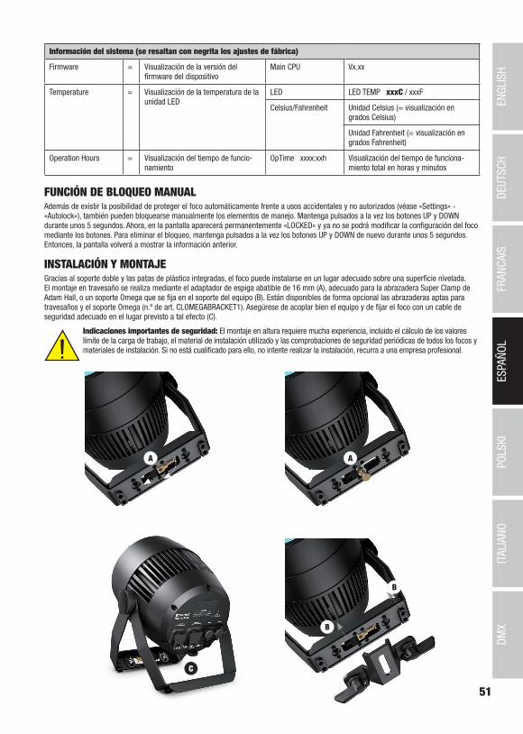
51
DMX
DEUTSC
HFRAN
CAIS
ESPAÑO
LEN
GLISH
ITALIANO
POLSKI
A
B
B
C
A
Información del sistema (se resaltan con negrita los ajustes de fábrica)
Firmware = Visualización de la versión del firmware del dispositivo
Main CPU Vx.xx
Temperature = Visualización de la temperatura de la unidad LED
LED LED TEMP xxxC / xxxF
Celsius/Fahrenheit Unidad Celsius (= visualización en grados Celsius)
Unidad Fahrenheit (= visualización en grados Fahrenheit)
Operation Hours = Visualización del tiempo de funcio-namiento
OpTime xxxx:xxh Visualización del tiempo de funciona-miento total en horas y minutos
FUNCIÓN DE BLOQUEO MANUALAdemás de existir la posibilidad de proteger el foco automáticamente frente a usos accidentales y no autorizados (véase «Settings» - «Autolock»), también pueden bloquearse manualmente los elementos de manejo. Mantenga pulsados a la vez los botones UP y DOWN durante unos 5 segundos. Ahora, en la pantalla aparecerá permanentemente «LOCKED» y ya no se podrá modificar la configuración del foco mediante los botones. Para eliminar el bloqueo, mantenga pulsados a la vez los botones UP y DOWN de nuevo durante unos 5 segundos. Entonces, la pantalla volverá a mostrar la información anterior.
INSTALACIÓN Y MONTAJEGracias al soporte doble y las patas de plástico integradas, el foco puede instalarse en un lugar adecuado sobre una superficie nivelada. El montaje en travesaño se realiza mediante el adaptador de espiga abatible de 16 mm (A), adecuado para la abrazadera Super Clamp de Adam Hall, o un soporte Omega que se fija en el soporte del equipo (B). Están disponibles de forma opcional las abrazaderas aptas para travesaños y el soporte Omega (n.º de art. CLOMEGABRACKET1). Asegúrese de acoplar bien el equipo y de fijar el foco con un cable de seguridad adecuado en el lugar previsto a tal efecto (C).
Indicaciones importantes de seguridad: El montaje en altura requiere mucha experiencia, incluido el cálculo de los valores límite de la carga de trabajo, el material de instalación utilizado y las comprobaciones de seguridad periódicas de todos los focos y materiales de instalación. Si no está cualificado para ello, no intente realizar la instalación, recurra a una empresa profesional.
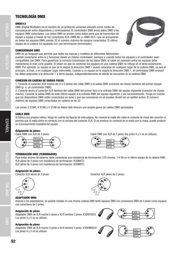
52
DMX
ITALIANOPOLSKI
ESPAÑOLFRANCAIS
DEUTSCHENGLISH
TECNOLOGÍA DMX
DMX512DMX (Digital Multiplex) es el nombre de un protocolo universal utilizado como medio de comunicación entre dispositivos y controladores. El controlador DMX envía datos DMX a los equipos DMX conectados. Los datos DMX se envían como datos serie que se transmiten de equipo a equipo a través de los conectores XLR «DMX IN» y «DMX OUT» que se encuentran en todos los equipos DMX, siendo 32 el número máximo de equipos conectados. El último equipo de la cadena irá equipado con una terminación (terminador).
CONEXIONADO DMXDMX es un lenguaje que permite que todas las marcas y modelos de diferentes fabricantes puedan conectarse entre sí y funcionar desde un mismo controlador, siempre y cuando todos los equipos y el controlador sean compatibles con DMX. Para garantizar la correcta transmisión de los datos DMX, el cable de conexión entre los equipos debe mantenerse lo más corto posible. El orden en que se conectan los equipos en una cadena DMX no influye en el direccionamiento DMX. Por ejemplo, un equipo al que se le asigna la dirección DMX 1 puede colocarse en cualquier lugar de la cadena DMX, ya sea al principio, al final, o en cualquier lugar intermedio. Cuando a un equipo se le asigna la dirección DMX 1, el controlador DMX enviará los datos asignados a la dirección 1 a dicho equipo, independientemente de dónde se encuentre en la cadena DMX.
CONEXIÓN EN CADENA DE VARIOS FOCOS1. Conecte el conector XLR macho de (3 o 5 pines) del cable DMX a la salida DMX (conector de chasis hembra) del primer equipo DMX (p. e. un controlador DMX).2. Conecte ahora el conector XLR hembra del cable DMX del primer foco a la entrada DMX del equipo siguiente (conector de chasis macho). Conecte la salida DMX de este último equipo a la entrada DMX del equipo siguiente, y así sucesivamente. Tenga en cuenta que los dispositivos DMX están conectados en serie y que las conexiones no se pueden dividir sin un splitter activo. El número máximo de equipos DMX conectados en cadena es de 32.
Las series 3 STAR, 4 STAR y 5 STAR de Adam Hall ofrecen una amplia gama de cables DMX apropiados.
CABLE DMX:Si fabrica sus propios cables, tenga en cuenta las figuras de esta página. No conecte la malla del cable al contacto de masa del conector ni permita que la malla entre en contacto con la carcasa del conector XLR. Si se produce un contacto de la malla con la masa, puede producir un funcionamiento inestable del equipo.
Asignación de pines:Cable DMX con XLR de 3 pines: Cable DMX con XLR de 5 pines (los pines 4 y 5 no se utilizan):
Shield
23
1
23
1
123
45
12
34
5
Shield
TERMINACIÓN DMX (TERMINADOR):Para evitar errores de sistema, debe conectarse una resistencia de terminación (120 ohmios, 1/4 W) en el último equipo de la cadena DMX.XLR aéreo de 3 pines con resistencia de terminación: K3DMXT3XLR aéreo de 5 pines con resistencia de terminación: K3DMXT5
Asignación de pines:Conector XLR aéreo de 3 pines: Conector XLR aéreo de 5 pines:
23
1
12
34
5
ADAPTADOR DMX:Gracias a los adaptadores, es posible instalar en una misma cadena DMX tanto equipos DMX con conexiones DMX de 3 pines como equipos con conectores de 5 pines.
Asignación de pinesAdaptador DMX de XLR macho 5 pines a XLR hembra 3 pines: K3DGF0020Los pines 4 y 5 no se utilizan.
Asignación de pinesAdaptador DMX de XLR macho 3 pines a XLR hembra 5 pines: K3DHM0020Los pines 4 y 5 no se utilizan.

53
DMX
DEUTSC
HFRAN
CAIS
ESPAÑO
LEN
GLISH
ITALIANO
POLSKI
Número de artículo: CLZZ180G2
Tipo de producto: washer LED
Tipo: foco para exteriores
Espectro cromático del LED: RGBW
Número de LED: 1
Tipo de LED: COB de 180W
Frecuencia de la modulación por ancho de pulsos (PWM) del LED:
800 Hz, 1200 Hz, 2000 Hz, 3600 Hz, 12 kHz, 25 kHz (ajustable)
Ángulo de dispersión: 10° - 40°
Entrada DMX: XLR macho de 5 pines, IP65
Salida DMX: XLR hembra de 5 pines, IP65
Modo DMX: 3 canales, 4 canales, 5 canales, 9 canales, 10 canales, 11 canales, 17 canales
Funciones DMX: atenuador, atenuador fino, RGBW, RGBW fino, estrobo, corrección de la temperatura de color, macros de color, cambio de color, fundido de colores, zoom, zoom fino, respuesta de atenuación, diversos ajustes de sistema
Funciones autónomas: macros de color, programas automáticos, modo estático, estrobo, color de usuario, Tunable White, modo Maestro / Esclavo
Configuración del sistema: giro de 180° de la imagen en pantalla, iluminación de la pantalla, DMX Fail, curvas de atenuación, respuesta de atenuación, calibración del color, función de bloqueo de la pantalla, frecuencia de la modulación por ancho de pulsos (PWM) del LED, restablecimiento de zoom, restablecimiento de los ajustes de fábrica, control de ventiladores
Control: DMX 512, habilitado para RDM
Elementos de manejo: MODE, ENTER, UP, DOWN (botones táctiles)
Elementos de visualización: pantalla OLED
Tensión de servicio: 100 - 240 V CA / 50 - 60Hz
Consumo de potencia: 220W
Intensidad de iluminación (a 1 m): 56.790 lx (ángulo estrecho)
Flujo luminoso (RGBW): 4900 lm
Conexión al suministro eléctrico: entrada y salida, tomas Power Twist con clase de protección IP65 (salida máxima 10 A)
Temperatura ambiente (en funcio-namiento):
-15 °C - +45 °C
Material de la carcasa: metal
Color de la carcasa: negro
Refrigeración de la carcasa: ventilador con clase de protección IP65 controlado por temperatura
Clase de protección: IP65
Dimensiones (ancho x alto x pro-fundo, sin soporte de montaje):
240 x 240 x 254 mm
Peso: 8,0 kg
Otras características: un cable de red de 1 m con conector Power Twist con clase de protección IP65, soporte de apoyo y montaje incluidos. Adaptador de espiga integrado de 16 mm. Soporte Omega y visera giratoria opcionalmente disponibles
DATOS TÉCNICOS
54
DMX
ITALIANOPOLSKI
ESPAÑOLFRANCAIS
DEUTSCHENGLISH
DECLARACIÓN DEL FABRICANTE
GARANTÍA DEL FABRICANTE Y LIMITACIÓN DE RESPONSABILIDAD Consulte nuestras condiciones de garantía y limitaciones de responsabilidad en: https://cdn-shop.adamhall.com/media/pdf/MANUFACTU-RERS-DECLARATIONS_CAMEO.pdf. En caso de necesitar servicio técnico, póngase en contacto con Adam Hall GmbH, Adam-Hall-Str. 1, 61267 Neu Anspach (Alemania); correo electrónico [email protected]; +49 (0)6081 / 9419-0.
ELIMINACIÓN CORRECTA DE ESTE PRODUCTO (Aplicable en la Unión Europea y en los países europeos que dispongan de un sistema de recogida selectiva) El símbolo que aparece sobre el producto o en la documentación adjunta indica que al final de la vida útil del equipo, no deberá desecharlo con los demás
residuos domésticos, con el fin de evitar posibles efectos negativos en el medio ambiente y en la salud humana debidos al vertido incontrolado de desechos. La recogida selectiva ayuda a su posterior reciclaje y fomenta la reutilización sostenible de los componentes de este equipo. Si es un particular, póngase en contacto con el distribuidor donde adquirió este producto, o con el ayuntamiento, para informarse sobre el reciclaje adecuado de este equipo. Si es una empresa, póngase en contacto con su proveedor para informarse sobre los términos y condiciones de su contrato de compra-venta. Este producto no debe mezclarse con otros residuos industriales.
Conformidad CEAdam Hall GmbH declara por la presente que este producto es conforme con las siguientes directivas (según sea aplicable):R&TTE (1999/5/CE) o RED (2014/53/UE) a partir de junio de 2017Directiva de baja tensión (2014/35/UE)Directiva EMC (2014/30/UE)RoHS (2011/65/UE)Puede consultar la declaración de conformidad completa en www.adamhall.com. También puede solicitarla a [email protected].

55
DMX
DEUTSC
HFRAN
CAIS
ESPAÑO
LEN
GLISH
ITALIANO
POLSKI
POLSKI
Gratulujemy wyboru!To urządzenie zostało zaprojektowane i wyprodukowane przy zastosowaniu najwyższych kryteriów jakościowych w celu zapewnienia wieloletniej bezawaryjnej eksploatacji. Proszę starannie przeczytać niniejszą instrukcję obsługi, aby móc jak najszybciej zacząć użytkować ten produkt marki Cameo Light. Więcej informacji na temat Cameo Light znajdą Państwo na naszej stronie internetowej pod adresem WWW.CAMEOLIGHT.COM.
ŚRODKI OSTROŻNOŚCI1. Należy dokładnie przeczytać niniejszą instrukcję. 2. Wszystkie informacje i instrukcje przechowywać w bezpiecznym miejscu. 3. Należy przestrzegać zaleceń. 4. Należy przestrzegać wszystkich wskazówek ostrzegawczych. Nie wolno usuwać wskazówek bezpieczeństwa ani innych informacji znajdujących się na urządzeniu. 5. Używać urządzenia wyłącznie w sposób zgodny z jego przeznaczeniem. 6. Stosować wyłącznie stabilne i pasujące statywy, ew. elementy mocujące (w przypadku instalacji stałych). Należy zadbać o prawidłową instalację uchwytów ściennych i ich odpowiednie zabezpieczenie. Zapewnić bezpieczną instalację urządzenia i upewnić się, że urządzenie nie spadnie. 7. Podczas instalacji przestrzegać obowiązujących w danym kraju przepisów bezpieczeństwa. 8. Urządzenie instalować i eksploatować z dala od grzejników, zasobników ciepła, pieców i innych źródeł ciepła. Zadbać o zainstalowanie urządzenia w taki sposób, aby zawsze było ono wystarczająco chłodzone i nie mogło ulec przegrzaniu. 9. Nie umieszczać na urządzeniu źródeł zapłonu, takich jak np. palące się świece. 10. Nie wolno blokować szczelin wentylacyjnych. 11. Urządzenie zostało zaprojektowane wyłącznie do użytku w pomieszczeniach. Nie używać urządzenia w bezpośrednim sąsiedztwie wody (nie dotyczy specjalnych urządzeń do stosowania na zewnątrz – w takim przypadku należy przestrzegać podanych poniżej wskazówek specjalnych). Urządzenie nie może mieć kontaktu z palnymi materiałami, płynami ani gazami. 12. Zabezpieczyć urządzenie przed wniknięciem kapiącej lub pryskającej wody. Nie wolno stawiać na urządzeniu pojemników napełnionych płynami, takich jak wazony czy naczynia z piciem. 13. Należy zadbać o to, aby do urządzenia nie wpadały żadne przedmioty. 14. Urządzenie można eksploatować tylko przy użyciu akcesoriów zalecanych i przewidzianych przez producenta. 15. Nie otwierać urządzenia ani nie dokonywać w nim zmian. 16. Po podłączeniu urządzenia sprawdzić wszystkie ciągi kablowe, aby zapobiec szkodom lub wypadkom np. w wyniku potknięcia. 17. Podczas transportu zadbać o to, aby urządzenie nie upadło, gdyż może to spowodować uszkodzenie mienia i obrażenia ciała.18. Jeśli urządzenie nie działa prawidłowo, do jego wnętrza dostały się płyny lub przedmioty lub jeśli urządzenie zostało uszkodzone w inny sposób, należy je natychmiast wyłączyć i odłączyć od gniazda sieciowego (jeśli urządzenie jest aktywne). Naprawę takiego urządzenia może wykonać tylko autoryzowany personel specjalistyczny. 19. Do czyszczenia urządzenia stosować suchą ściereczkę. 20. Przestrzegać obowiązujących w danym kraju przepisów dotyczących usuwania odpadów. Podczas utylizacji opakowania oddzielić tworzywo sztuczne od papieru i tektury. 21. Worki z tworzywa sztucznego należy przechowywać w miejscu niedostępnym dla dzieci.
DOTYCZY URZĄDZEŃ Z ZASILANIEM SIECIOWYM:22. UWAGA: jeśli kabel sieciowy urządzenia jest wyposażony w zestyk ochronny, należy go podłączyć do gniazda z przewodem uziemia-jącym. Nigdy nie wolno dezaktywować przewodu uziemiającego kabla sieciowego. 23. Nie włączać urządzenia bezpośrednio po narażeniu go na silne wahania temperatury (np. po transporcie). Wilgoć i skropliny mogą uszkodzić urządzenie. Włączyć urządzenie dopiero wtedy, gdy osiągnie temperaturę pokojową. 24. Przed podłączeniem urządzenia do gniazda elektrycznego należy sprawdzić, czy napięcie i częstotliwość sieci elektrycznej odpowi-ada wartościom podanym na urządzeniu. Jeśli urządzenie jest wyposażone w przełącznik napięcia, należy podłączyć je do gniazda tylko wówczas, gdy wartości urządzenia odpowiadają wartościom sieci elektrycznej. Jeśli dołączony kabel sieciowy lub dołączony adapter sieciowy nie pasuje do gniazda elektrycznego, należy skontaktować się z elektrykiem. 25. Nie stawać na kablu sieciowym. Należy zadbać o to, aby kable przewodzące napięcie nie były zagięte przy gnieździe sieciowym, przy adapterze sieciowym ani przy gnieździe urządzenia. 26. Przy podłączaniu urządzenia zawsze należy zadbać o to, aby kabel sieciowy lub adapter sieciowy był zawsze łatwo dostępny. Odłączyć urządzenie od źródła zasilania, gdy nie jest ono używane lub gdy ma zostać poddane czyszczeniu. Zawsze należy wyjmować kabel sieciowy i adapter sieciowy z gniazda, chwytając za wtyczkę lub adapter, a nie za kabel. Nigdy nie dotykać kabla sieciowego i adaptera sieciowego mokrymi dłońmi. 9. W miarę możliwości nie włączać i wyłączać urządzenia w krótkich odstępach czasu, gdyż może to mieć negatywny wpływ na jego żywotność.28. WAŻNA INFORMACJA: bezpieczniki należy wymieniać wyłącznie na bezpieczniki tego samego typu i o takich samych wartościach. Jeśli bezpiecznik stale się przepala, należy skontaktować się z autoryzowanym centrum serwisowym. 29. Aby całkowicie odłączyć urządzenie od sieci, należy wyjąć kabel sieciowy lub adapter sieciowy z gniazda. 30. Jeśli urządzenie jest wyposażone w przyłącze sieciowe Volex, konieczne jest odblokowanie odpowiedniej wtyczki urządzenia Volex, zanim będzie możliwe jej odłączenie. Oznacza to także, iż w wyniku pociągnięcia za kabel urządzenie może się przesunąć i spaść, co może spowodować obrażenia ciała i/lub inne szkody, dlatego ważne jest, aby przewody były odpowiednio poprowadzone. 31. W przypadku zagrożenia uderzeniem pioruna lub jeśli urządzenie przez dłuższy czas nie jest używane, należy wyjąć kabel sieciowy i adapter sieciowy z gniazda.

56
DMX
ITALIANOPOLSKI
ESPAÑOLFRANCAIS
DEUTSCHENGLISH
32. Instalacja urządzenia powinna odbywać się, gdy urządzenie nie jest podłączone do źródła zasilania (należy wyjąć wtyczkę z gniazda).33. Kurz i inne osady wewnątrz urządzenia mogą je uszkodzić. W zależności od warunków otoczenia (kurz, nikotyna, opary itp.) urządzenie powinno być konserwowane lub czyszczone przez wykwalifikowanego specjalistę (usługa nieobjęta gwarancją), aby zapobiec przegrzaniu i nieprawidłowemu działaniu.34: Odstęp od materiałów łatwopalnych musi wynosić co najmniej 0,5 m.35. Powierzchnia przekroju poprzecznego przewodów zasilających większą liczbę urządzeń musi wynosić co najmniej 1,5 mm². W krajach Unii Europejskiej przewody muszą spełniać wymagania normy H05VV-F lub podobne wytyczne. Adam Hall oferuje odpowiednie przewody. Używając tych przewodów można podłączyć większą liczbę urządzeń przez złącze Power out i Power in kolejnego urządzenia. Należy upew-nić się, że całkowity pobór mocy wszystkich podłączonych urządzeń nie przekracza wartości podanej w amperach na urządzeniu. Należy dopilnować, aby kable łączące poszczególne urządzenia były możliwie jak najkrótsze.
UWAGA:Nigdy nie zdejmować pokrywy, gdyż grozi to porażeniem prądem. We wnętrzu urządzenia nie ma żadnych części, które mogłyby zostać naprawione bądź poddane czynnościom konserwacyjnym przez użytkownika. Czynności konserwacyjne i naprawy może przeprowadzać wyłącznie wykwa-lifikowany personel serwisowy.
Trójkąt równoboczny z symbolem błyskawicy sygnalizuje nieizolowane, niebezpieczne napięcie we wnętrzu urządzenia, które może spowodować porażenie prądem.
Trójkąt równoboczny z wykrzyknikiem oznacza ważne wskazówki dotyczące obsługi i konserwacji.
Ostrzeżenie! Ten symbol ostrzega przed gorącymi powierzchniami. Podczas użytkowania niektóre elementy mogą się nagrzać. Urządzenie można dotykać lub transportować dopiero po jego ostygnięciu (po odczekaniu co najmniej 10 minut).
Ostrzeżenie! To urządzenie przeznaczone jest do użytku do maksymalnej wysokości 2000 m n.p.m.
Ostrzeżenie! To urządzenie nie jest przewidziane do użytku w tropikalnych strefach klimatycznych.
Uwaga! Intensywne źródło światła LED! Niebezpieczeństwo uszkodzenia wzroku. Nie spoglądaj na źródło światła.
OSTROŻNIE! WAŻNE WSKAZÓWKI DOTYCZĄCE PRODUKTÓW OŚWIETLENIOWYCH!1. Produkt przeznaczony jest do zastosowań profesjonalnych podczas organizacji imprez i nie nadaje się do oświetlania pomieszczeń w gospodarstwie domowym.2. Nigdy nie spoglądać bezpośrednio w stronę promienia świetlnego, nawet przez krótką chwilę. 3. Nigdy nie spoglądać w stronę promienia świetlnego przy pomocy urządzeń optycznych, takich jak np. szkło powiększające.4. Efekty stroboskopowe mogą wywołać ataki epilepsji u osób wrażliwych na pulsujące światło! Dlatego osoby chorujące na epilepsję powinny unikać miejsc, w których stosowane są stroboskopy.
WPROWADZENIEOUTDOOR ZENIT ZOOM 180 G2
CLZZ180G2
FUNKCJE STEROWANIA
Sterowanie DMX 3-kanałowe, 4-kanałowe, 5-kanałowe, 9-kanałowe, 10-kanałowe, 11-kanałowe i 17-kanałowe
Tryb pracy master / slave
Funkcje standalone

57
DMX
DEUTSC
HFRAN
CAIS
ESPAÑO
LEN
GLISH
ITALIANO
POLSKI
5
1 2 3 44
7
8
6
CHARAKTERYSTYKA
Reflektor zewnętrzny z funkcją zoomu i diodą COB-LED 180 W (RGBW). 7 trybów DMX. Sterowanie DMX-512. Tryb pracy master/ slave. Funkcje standalone. W zestawie uchwyt do ustawienia lub montażu i adapter gwintowy 16 mm. Napięcie robocze: 100–240 V AC / 50–60 Hz. pobór mocy 220 W. Stopień ochrony IP65.
Reflektory mogą również pracować w standardzie RDM (Remote Device Management). Jest to system zdalnego sterowania urządzeniem, który umożliwia sprawdzanie statusu i konfigurowanie urządzeń końcowych RDM za pomocą sterownika RDM.
GNIAZDA, ELEMENTY OBSŁUGI I WSKAŹNIKI
1 POWER IN
Gniazdo wejściowe zasilania sieciowego Power Twist IP65 z gumową zaślepką. Napięcie robocze 100–240 V AC / 50–60 Hz. Podłączanie za pomocą zawartego w zestawie kabla sieciowego (nieużywane gniazdo zawsze należy zabezpieczać gumową zaślepką).
2 POWER OUT
Gniazdo wyjściowe zasilania sieciowego Power Twist IP65 z gumową zaślepką. Źródło zasilania dla dodatkowych reflektorów CAMEO. Całkowity pobór prądu wszystkich podłączonych urządzeń nie może przekroczyć wartości w amperach (A) podanej na urządzeniu (nieuży-wane gniazdo zawsze należy zabezpieczać gumową zaślepką).
3 DMX IN
Męskie 5-pinowe złącze XLR IP65 do podłączania sterownika DMX (np. pulpitu DMX; nieużywane gniazdo zawsze należy zabezpieczać gumową zaślepką).
4 DMX OUT
Żeńskie 5-pinowe złącze XLR IP65 do przekazywania sygnału sterującego DMX (nieużywane gniazdo zawsze należy zabezpieczać gumową zaślepką).
5 WYŚWIETLACZ OLED
Wyświetla bieżący tryb pracy oraz inne ustawienia systemowe.
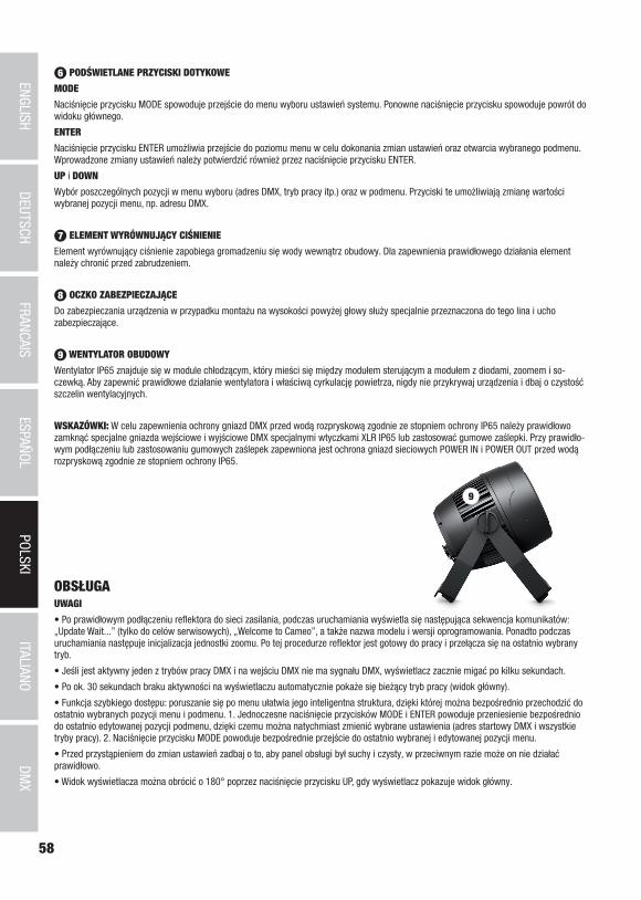
58
DMX
ITALIANOPOLSKI
ESPAÑOLFRANCAIS
DEUTSCHENGLISH
6 PODŚWIETLANE PRZYCISKI DOTYKOWE
MODE
Naciśnięcie przycisku MODE spowoduje przejście do menu wyboru ustawień systemu. Ponowne naciśnięcie przycisku spowoduje powrót do widoku głównego.
ENTER
Naciśnięcie przycisku ENTER umożliwia przejście do poziomu menu w celu dokonania zmian ustawień oraz otwarcia wybranego podmenu. Wprowadzone zmiany ustawień należy potwierdzić również przez naciśnięcie przycisku ENTER.
UP i DOWN
Wybór poszczególnych pozycji w menu wyboru (adres DMX, tryb pracy itp.) oraz w podmenu. Przyciski te umożliwiają zmianę wartości wybranej pozycji menu, np. adresu DMX.
7 ELEMENT WYRÓWNUJĄCY CIŚNIENIE
Element wyrównujący ciśnienie zapobiega gromadzeniu się wody wewnątrz obudowy. Dla zapewnienia prawidłowego działania element należy chronić przed zabrudzeniem.
8 OCZKO ZABEZPIECZAJĄCE
Do zabezpieczania urządzenia w przypadku montażu na wysokości powyżej głowy służy specjalnie przeznaczona do tego lina i ucho zabezpieczające.
9 WENTYLATOR OBUDOWY
Wentylator IP65 znajduje się w module chłodzącym, który mieści się między modułem sterującym a modułem z diodami, zoomem i so-czewką. Aby zapewnić prawidłowe działanie wentylatora i właściwą cyrkulację powietrza, nigdy nie przykrywaj urządzenia i dbaj o czystość szczelin wentylacyjnych.
WSKAZÓWKI: W celu zapewnienia ochrony gniazd DMX przed wodą rozpryskową zgodnie ze stopniem ochrony IP65 należy prawidłowo zamknąć specjalne gniazda wejściowe i wyjściowe DMX specjalnymi wtyczkami XLR IP65 lub zastosować gumowe zaślepki. Przy prawidło-wym podłączeniu lub zastosowaniu gumowych zaślepek zapewniona jest ochrona gniazd sieciowych POWER IN i POWER OUT przed wodą rozpryskową zgodnie ze stopniem ochrony IP65.
9
OBSŁUGAUWAGI
• Po prawidłowym podłączeniu reflektora do sieci zasilania, podczas uruchamiania wyświetla się następująca sekwencja komunikatów: „Update Wait...” (tylko do celów serwisowych), „Welcome to Cameo”, a także nazwa modelu i wersji oprogramowania. Ponadto podczas uruchamiania następuje inicjalizacja jednostki zoomu. Po tej procedurze reflektor jest gotowy do pracy i przełącza się na ostatnio wybrany tryb.
• Jeśli jest aktywny jeden z trybów pracy DMX i na wejściu DMX nie ma sygnału DMX, wyświetlacz zacznie migać po kilku sekundach.
• Po ok. 30 sekundach braku aktywności na wyświetlaczu automatycznie pokaże się bieżący tryb pracy (widok główny).
• Funkcja szybkiego dostępu: poruszanie się po menu ułatwia jego inteligentna struktura, dzięki której można bezpośrednio przechodzić do ostatnio wybranych pozycji menu i podmenu. 1. Jednoczesne naciśnięcie przycisków MODE i ENTER powoduje przeniesienie bezpośrednio do ostatnio edytowanej pozycji podmenu, dzięki czemu można natychmiast zmienić wybrane ustawienia (adres startowy DMX i wszystkie tryby pracy). 2. Naciśnięcie przycisku MODE powoduje bezpośrednie przejście do ostatnio wybranej i edytowanej pozycji menu.
• Przed przystąpieniem do zmian ustawień zadbaj o to, aby panel obsługi był suchy i czysty, w przeciwnym razie może on nie działać prawidłowo.
• Widok wyświetlacza można obrócić o 180° poprzez naciśnięcie przycisku UP, gdy wyświetlacz pokazuje widok główny.
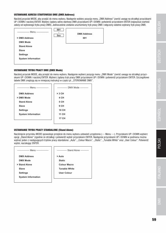
59
DMX
DEUTSC
HFRAN
CAIS
ESPAÑO
LEN
GLISH
ITALIANO
POLSKI
USTAWIANIE ADRESU STARTOWEGO DMX (DMX Address)
Naciśnij przycisk MODE, aby przejść do menu wyboru. Następnie wybierz pozycję menu „DMX Address” (zwróć uwagę na strzałkę) przyciskami UP i DOWN i naciśnij ENTER. Wybierz żądany adres startowy DMX przyciskami UP i DOWN i potwierdź przyciskiem ENTER (najwyższa wartość zależy od wybranego trybu pracy DMX). Jednocześnie zostanie uruchomiony tryb pracy DMX i włączony ostatnio wybrany tryb pracy DMX.
---------------- Menu ----------------
DMX Address
DMX Mode
Stand Alone
Slave
Settings
System Information
001
5xx- DMX Address
001
USTAWIANIE TRYBU PRACY DMX (DMX Mode)
Naciśnij przycisk MODE, aby przejść do menu wyboru. Następnie wybierz pozycję menu „DMX Mode” (zwróć uwagę na strzałkę) przyci-skami UP i DOWN i naciśnij ENTER. Wybierz żądany tryb pracy DMX przyciskami UP i DOWN i potwierdź przyciskiem ENTER. Szczegółowe tabele DMX znajdują się w niniejszej instrukcji w części pt. „STEROWANIE DMX”.
---------------- Menu ----------------
DMX Address
DMX Mode
Stand Alone
Slave
Settings
System Information
------------- DMX Mode -----------
3 CH
4 CH
5 CH
9 CH
10 CH
11 CH
17 CH
USTAWIANIE TRYBU PRACY STANDALONE (Stand Alone)
Naciśnięcie przycisku MODE spowoduje przejście do menu wyboru ustawień urządzenia (--- Menu ---). Przyciskami UP i DOWN wybierz opcję „Stand Alone” (zgodnie ze strzałką) i potwierdź wybór przyciskiem ENTER. Następnie przyciskami UP i DOWN w podmenu można wybrać jeden z następujących trybów pracy standalone: „Auto”, „Colour Macro”, „Static”, „Tunable White” oraz „User Colour”. Potwierdź wybór, naciskając ENTER.
---------------- Menu ----------------
DMX Address
DMX Mode
Stand Alone
Slave
Settings
System Information
------------- Stand Alone -----------
Auto
Static
Colour Macro
Tunable White
User Colour

60
DMX
ITALIANOPOLSKI
ESPAÑOLFRANCAIS
DEUTSCHENGLISH
TRYB PRACY STANDALONE „AUTO” (Auto Program 1–6)
Każdy z 6 różnych programów automatycznych zawiera zaprogramowane sekwencje zmian kolorów. Jasność oraz prędkość ruchu można ustawiać oddzielnie. Najpierw wybierz tryb pracy automatycznej i potwierdź przyciskiem ENTER zgodnie z opisem w punkcie USTAWIANIE TRYBU PRACY STANDALONE. Przyciskami UP i DOWN wybierz jeden z 6 programów automatycznych (zgodnie ze strzałką) i potwierdź przy-ciskiem ENTER. Aby ustawić jasność, za pomocą przycisków UP i DOWN wybierz pozycję menu „Dimmer”, potwierdź przyciskiem ENTER, a następnie przyciskami UP i DOWN wybierz żądaną wartość z zakresu od 000 do 100. Potwierdź, naciskając ENTER. Aby ustawić prędkość ruchu, wybierz opcję „Speed”, potwierdź przyciskiem ENTER, a następnie wybierz żądaną wartość z zakresu od 000 do 100. W ten sam sposób wprowadź ustawienia dla funkcji zoom. Potwierdź wszystkie zmiany, naciskając ENTER.
Mode
Auto
-------- Stand Alone -------
Auto
Static
Colour Macro
Tunable White
User Colour
----------- Auto -----------
Program 1
Program 2
Program 3
Program 4
Program 5
Program 6
--------- Program x ---------
Dimmer <100>
Speed <100>
Zoom <100>
000
100-
Dimmer Speed
000
100-
TRYB PRACY STANDALONE „STATYCZNY” (Static)
Tryb statyczny umożliwia, podobnie jak sterownik DMX, ustawienie ściemniacza, stroboskopu oraz wartości R, G, B i W itd. bezpośrednio w urządzeniu w przedziale od 000 do 255. Dzięki temu można utworzyć pojedynczą scenę bez dodatkowego sterownika DMX. Wybierz tryb statyczny zgodnie z opisem w punkcie „USTAWIANIE TRYBU PRACY STANDALONE” i potwierdź przyciskiem ENTER. Przyciskami UP i DOWN wybierz punkt menu, którego ustawienia chcesz zmienić (zgodnie ze strzałką), a następnie potwierdź przyciskiem ENTER. Na wyświetlaczu pojawi się trzycyfrowe pole, w którym przyciskami UP i DOWN możesz ustawić żądaną wartość z zakresu od 000 do 255. Potwierdź, naci-skając ENTER. Wartości służące do ustawienia funkcji stroboskopu odpowiadają wartościom stroboskopu wielofunkcyjnego w tabelach DMX.
Mode
Static
-------- Stand Alone -------
Auto
Static
Colour Macro
Tunable White
User Colour
----------- Static -----------
Dimmer <255>
DimFine <255>
Strobe <255>
Red <255>
Green <255>
Blue <255>
White <255>
Colour Temp <255>
Zoom <255>
Zoom Fine <255>
000
255-
Zoom
000
100-
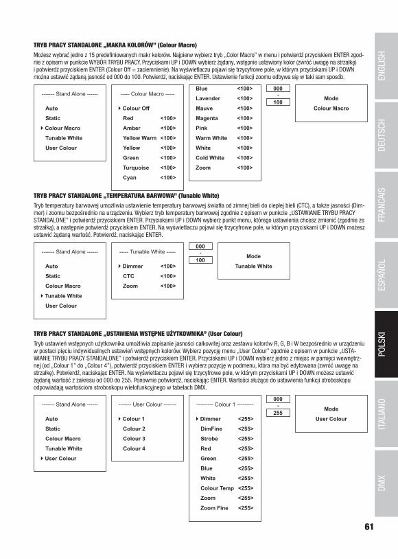
61
DMX
DEUTSC
HFRAN
CAIS
ESPAÑO
LEN
GLISH
ITALIANO
POLSKI
TRYB PRACY STANDALONE „MAKRA KOLORÓW” (Colour Macro)
Możesz wybrać jedno z 15 predefiniowanych makr kolorów. Najpierw wybierz tryb „Color Macro” w menu i potwierdź przyciskiem ENTER zgod-nie z opisem w punkcie WYBÓR TRYBU PRACY. Przyciskami UP i DOWN wybierz żądany, wstępnie ustawiony kolor (zwróć uwagę na strzałkę) i potwierdź przyciskiem ENTER (Colour Off = zaciemnienie). Na wyświetlaczu pojawi się trzycyfrowe pole, w którym przyciskami UP i DOWN można ustawić żądaną jasność od 000 do 100. Potwierdź, naciskając ENTER. Ustawienie funkcji zoomu odbywa się w taki sam sposób.
Mode
Colour Macro
------- Stand Alone ------
Auto
Static
Colour Macro
Tunable White
User Colour
----- Colour Macro -----
Colour Off
Red <100>
Amber <100>
Yellow Warm <100>
Yellow <100>
Green <100>
Turquoise <100>
Cyan <100>
000
100-
Blue <100>
Lavender <100>
Mauve <100>
Magenta <100>
Pink <100>
Warm White <100>
White <100>
Cold White <100>
Zoom <100>
TRYB PRACY STANDALONE „TEMPERATURA BARWOWA” (Tunable White)
Tryb temperatury barwowej umożliwia ustawienie temperatury barwowej światła od zimnej bieli do ciepłej bieli (CTC), a także jasności (Dim-mer) i zoomu bezpośrednio na urządzeniu. Wybierz tryb temperatury barwowej zgodnie z opisem w punkcie „USTAWIANIE TRYBU PRACY STANDALONE” i potwierdź przyciskiem ENTER. Przyciskami UP i DOWN wybierz punkt menu, którego ustawienia chcesz zmienić (zgodnie ze strzałką), a następnie potwierdź przyciskiem ENTER. Na wyświetlaczu pojawi się trzycyfrowe pole, w którym przyciskami UP i DOWN możesz ustawić żądaną wartość. Potwierdź, naciskając ENTER.
Mode
Tunable White
------- Stand Alone ------
Auto
Static
Colour Macro
Tunable White
User Colour
----- Tunable White -----
Dimmer <100>
CTC <100>
Zoom <100>
000
100-
TRYB PRACY STANDALONE „USTAWIENIA WSTĘPNE UŻYTKOWNIKA” (User Colour)
Tryb ustawień wstępnych użytkownika umożliwia zapisanie jasności całkowitej oraz zestawu kolorów R, G, B i W bezpośrednio w urządzeniu w postaci pięciu indywidualnych ustawień wstępnych kolorów. Wybierz pozycję menu „User Colour” zgodnie z opisem w punkcie „USTA-WIANIE TRYBU PRACY STANDALONE” i potwierdź przyciskiem ENTER. Przyciskami UP i DOWN wybierz jedno z miejsc w pamięci wewnętrz-nej (od „Colour 1” do „Colour 4”), potwierdź przyciskiem ENTER i wybierz pozycję w podmenu, która ma być edytowana (zwróć uwagę na strzałkę). Potwierdź, naciskając ENTER. Na wyświetlaczu pojawi się trzycyfrowe pole, w którym przyciskami UP i DOWN możesz ustawić żądaną wartość z zakresu od 000 do 255. Ponownie potwierdź, naciskając ENTER. Wartości służące do ustawienia funkcji stroboskopu odpowiadają wartościom stroboskopu wielofunkcyjnego w tabelach DMX.
Mode
User Colour
------- Stand Alone ------
Auto
Static
Colour Macro
Tunable White
User Colour
--------- Colour 1 ---------
Dimmer <255>
DimFine <255>
Strobe <255>
Red <255>
Green <255>
Blue <255>
White <255>
Colour Temp <255>
Zoom <255>
Zoom Fine <255>
000
255-------- User Colour -------
Colour 1
Colour 2
Colour 3
Colour 4

62
DMX
ITALIANOPOLSKI
ESPAÑOLFRANCAIS
DEUTSCHENGLISH
TRYB PRACY SLAVE
Naciśnij przycisk MODE, aby przejść do menu wyboru. Przyciskami UP i DOWN wybierz opcję „Slave” (zgodnie ze strzałką) i potwierdź wybór przyciskiem ENTER. Połącz jednostki slave i master (ten sam model) kablem DMX i włącz w jednostce master jeden z trybów pracy standalone (Auto, Static, Colour Macro, Tunable White, User Colour). Praca jednostki slave jest teraz dostosowana do pracy urządzenia master. W przypadku braku sygnału sterującego znaki na wyświetlaczu migają. Po wykryciu sygnału sterującego miganie ustanie.
---------------- Menu ----------------
DMX Address
DMX Mode
Stand Alone
Slave
Settings
System Information
Mode
Slave
USTAWIENIA URZĄDZENIA (Settings)
Naciśnij przycisk MODE, aby przejść do menu wyboru. Przyciskami UP i DOWN wybierz opcję „Settings” (zgodnie ze strzałką) i potwierdź wybór przyciskiem ENTER.
---------------- Menu ----------------
DMX Address
DMX Mode
Stand Alone
Slave
Settings
System Information
Nastąpi przejście do podmenu, w którym można dokonać następujących ustawień (wybór przyciskami UP i DOWN, potwierdzenie wyboru przyciskiem ENTER, zmiana wartości lub statusu przyciskami UP i DOWN, potwierdzanie przyciskiem ENTER):
Settings (pogrubiona czcionka = ustawienie fabryczne)Display Reverse = Obracanie obrazu wyświ-
etlaczaOn obrócenie obrazu wyświetlacza o 180° (np. przy
montażu urządzenia „do góry nogami”)Off obraz wyświetlacza nie obraca się
Display Backlight = podświetlenie wyświetlacza i przycisków
On stale włączoneOff wyłączenie po ok. 30 sekundach bezczynności
DMX Fail = tryb pracy w przypadku przerwania sygnału DMX
Hold ostatnie polecenie zostanie wykonaneBlackout natychmiastowe wygaszenie reflektora
Dimmer Curve = krzywa ściemniacza Linear natężenie światła wzrasta liniowo wraz ze wzrostem wartości DMX
Exponential natężenie światła można ustawić precyzyjnie w dol-nym zakresie wartości DMX oraz ogólnie w górnym zakresie wartości DMX
Logarithmic natężenie światła można ustawić ogólnie w dolnym zakresie wartości DMX oraz precyzyjnie w górnym zakresie wartości DMX
S-Curve natężenie światła można ustawić precyzyjnie w górnym i dolnym zakresie wartości DMX oraz ogólnie w środkowym zakresie wartości DMX
DimmerResponse
= Charakterystyka ściemniania LED Reflektor reaguje gwałtownie na zmianę wartości DMX
Halogen Zmiana jasności reflektora następuje łagodnie, podob-nie jak w przypadku reflektora halogenowego
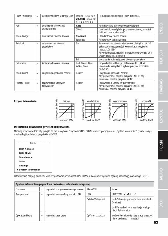
63
DMX
DEUTSC
HFRAN
CAIS
ESPAÑO
LEN
GLISH
ITALIANO
POLSKI
PWM-Frequency = Częstotliwość PWM lampy LED 800 Hz / 1200 Hz / 2000 Hz / 3600 Hz / 12 kHz / 25 kHz
Regulacja częstotliwości PWM lampy LED
Fan = Ustawienia sterowania wentylatorem
Auto Automatyczne sterowanie wentylatoremSilent bardzo cichy wentylator przy zredukowanej jasności,
jeśli jest taka koniecznośćZoom Range Ustawienia zakresu zoomu Standard Standardowy zakres zoomu
Extended Rozszerzony zakres zoomuAutolock = automatyczna blokada
przyciskówOn Automatyczna blokada elementów obsługi po ok. 30
sekundach bezczynności. Komunikat na wyświet-laczu: „LOCKED” Aby odblokować, naciśnij jednocześnie przyciski UP i DOWN przez ok. 5 sekund
Off wyłączenie automatycznej blokady przyciskówCalibration = kalibracja kolorów i zoomu Red, Green, Blue,
White, Zoom Indywidualna kalibracja. Ustawienie R, G, B, W i zoomu dla wszystkich trybów pracy w przedziale 000–255
Zoom Reset = inicjalizacja jednostki zoomu Reset? Inicjalizacja jednostki zoomu: aby potwierdzić, naciśnij przycisk ENTER; aby anulować, naciśnij przycisk MODE
Factory Reset = przywracanie ustawień fabrycznych
Reset? Przywracanie ustawień fabrycznych: aby potwierdzić, naciśnij przycisk ENTER; aby anulować, naciśnij przycisk MODE
liniowa
wartość DMXinte
nsyw
ność
św
iatła wykładnicza
wartość DMXinte
nsyw
ność
św
iatła logarytmiczna
wartość DMXinte
nsyw
ność
św
iatła krzywa S
wartość DMXinte
nsyw
ność
św
iatłakrzywe ściemniania
INFORMACJE O SYSTEMIE (SYSTEM INFORMATION)
Naciśnij przycisk MODE, aby przejść do menu wyboru. Przyciskami UP i DOWN wybierz pozycję menu „System Information” (zwróć uwagę na strzałkę) i potwierdź przyciskiem ENTER.
---------------- Menu ----------------
DMX Address
DMX Mode
Stand Alone
Slave
Settings
System Information
Odpowiednią pozycję podmenu wybierz ponownie przyciskami UP i DOWN, a następnie wyświetl żądaną informację, naciskając ENTER.
System Information (pogrubiona czcionka = ustawienie fabryczne)
Firmware = wyświetl oprogramowanie sprzętowe Main CPU Vx.xx
Temperature = wyświetl temperaturę modułu LED LED LED TEMP xxxC / xxxF
Celsius/Fahrenheit Unit Celsius (= prezentacja w stopniach Celsiusa)
Unit Fahrenheit (= prezentacja w stop-niach Fahrenheita)
Operation Hours = wyświetl czas pracy OpTime xxxx:xxh wyświetla całkowity czas pracy urządze-nia w godzinach i minutach

64
DMX
ITALIANOPOLSKI
ESPAÑOLFRANCAIS
DEUTSCHENGLISH
A
B
BC
A
RĘCZNA FUNKCJA BLOKOWANIAOprócz automatycznego zabezpieczenia reflektora przed omyłkowym wprowadzeniem zmian lub nieuprawnionym dostępem (patrz „Settin-gs” – „Autolock”) możliwe jest także ręczne zablokowanie elementów obsługi. Równocześnie wciśnij przyciski UP i DOWN i przytrzymaj je przez ok. 5 sekund. Teraz wyświetli się w sposób ciągły komunikat „LOCKED” i zmiana ustawień reflektora przy użyciu przycisków będzie niemożliwa. Aby odblokować urządzenie, ponownie naciśnij jednocześnie przyciski UP i DOWN i przytrzymaj je przez ok. 5 sekund. Na wyświetlaczu ukaże się ostatnio wyświetlana informacja.
USTAWIANIE I MONTAŻDo ustawienia reflektora w odpowiednim miejscu na płaskiej powierzchni służy podwójny uchwyt i zamontowane na stałe nóżki z tworzywa sztucznego. Montaż na kratownicy odbywa się albo za pomocą rozkładanego adaptera gwintowego 16 mm (A, nadaje się do Adam Hall Super Clamp) albo uchwytu Omega, który mocuje się na uchwycie urządzenia (B). Odpowiednie zaciski do kratownic oraz uchwyt Omega (nr art. CLOMEGABRACKET1) są dostępne jako opcja. Należy zapewnić stałe połączenia i zamocować reflektor odpowiednią liną zabezpieczają-cą w wyznaczonym miejscu (C).
Ważne zasady bezpieczeństwa: Montaż nad głową wymaga dużego doświadczenia, m.in. w zakresie obliczania limitów obciążenia roboczego stosowanych materiałów instalacyjnych oraz okresowych przeglądów bezpieczeństwa wszystkich mate-riałów instalacyjnych i reflektorów. Użytkownik bez odpowiednich kwalifikacji nie powinien wykonywać instalacji samodzielnie, lecz skorzystać z pomocy profesjonalnych firm.

65
DMX
DEUTSC
HFRAN
CAIS
ESPAÑO
LEN
GLISH
ITALIANO
POLSKI
TECHNIKA DMX
DMX-512DMX (Digital Multiplex) to nazwa uniwersalnego protokołu transmisji do komunikacji między odpowiednimi urządzeniami a kontrolerami. Kontroler DMX wysyła dane DMX do podłączonych urządzeń DMX. Transmisja danych DMX następuje zawsze w formie szeregowego strumienia danych, który jest przekazywany z jednego urządzenia do następnego przez znajdujące się w każdym urządzeniu obsługującym standard DMX złącza „DMX IN” i „DMX OUT” (złącza wtykowe XLR), przy czym maksymalna liczba urządzeń nie może przekraczać 32. Ostatnie urządzenie w łańcuchu należy wyposażyć w terminator.
ZŁĄCZE DMX:DMX to wspólny „język”, za pomocą którego różne typy i modele urządzeń różnych producentów porozumiewają się ze sobą i mogą być sterowane przy użyciu centralnego kontrolera, o ile wszystkie urządzenia i kontroler obsługują standard DMX. W celu zapewnienia optymalnej transmisji danych wymagane jest, aby kable połączeniowe między poszczególnymi urządzeniami były możliwie jak najkrótsze. Kolejność, w jakiej urządzenia są podłączone do sieci DMX, nie ma znaczenia dla adresowania. I tak urządzenie z adresem DMX 1 może znajdować się w dowolnym miejscu (szeregowego) łańcucha DMX – na początku, na końcu lub gdzieś pośrodku. Po przydzieleniu urządzeniu adresu DMX 1, kontroler „wie”, że ma on wysyłać wszystkie dane przypisane do adresu 1 do tego urządzenia, niezależnie od jego pozycji w sieci DMX. POŁĄCZENIE SZEREGOWE KILKU REFLEKTORÓW1. Męską wtyczkę XLR (3-stykową lub 5-stykową) kabla DMX podłączyć do wyjścia DMX (żeńskie gniazdo XLR) pierwszego urządzenia DMX (np. kontrolera DMX).2. Żeńską wtyczkę XLR kabla DMX podłączonego do pierwszego reflektora podłączyć do wejścia DMX (męskie gniazdo XLR) następnego urządzenia DMX. Wyjście DMX tego urządzenia podłączyć w taki sam sposób do wejścia DMX następnego urządzenia i tak dalej. Należy pamiętać, że urządzenia DMX podłącza się szeregowo, a połączeń nie można rozdzielać bez aktywnego rozdzielacza. Maksymalna liczba urządzeń DMX w łańcuchu DMX nie może przekraczać 32.
Obszerny wybór odpowiednich kabli DMX oferują linie produktów Adam Hall 3 STAR, 4 STAR i 5 STAR.
KABEL DMX:W przypadku stosowania własnych kabli należy bezwzględnie przestrzegać informacji podanych na ilustracjach na tej stronie. W żadnym wypadku nie wolno łączyć osłony kabla z końcówką uziemiającą wtyczki. Należy także pamiętać, aby osłona nie miała kontaktu z obudową wtyczki XLR. Jeśli osłona ma kontakt z uziemieniem, może dojść do awarii systemu.
Przyporządkowanie wtyczek:Kabel DMX z 3-stykowymi wtyczkami XLR: Kabel DMX z 5-stykowymi wtyczkami XLR (pin 4 i 5 są niepodłączone):
Shield
23
1
23
1
123
45
12
34
5
Shield
TERMINATOR DMX:Aby zapobiec awariom systemu, należy wyposażyć ostatnie urządzenie w łańcuchu DMX w terminator (120 Ω, 1/4 W).3-stykowa wtyczka XLR z terminatorem: K3DMXT35-stykowa wtyczka XLR z terminatorem: K3DMXT5
Przyporządkowanie wtyczek:3-stykowa wtyczka XLR: 5-stykowa wtyczka XLR:
23
1
12
34
5
ADAPTER DMX:Możliwa jest także kombinacja urządzeń DMX z 3-stykowymi przyłączami i urządzeń DXM z 5-stykowymi przyłączami w jednym łańcuchu DMX przy użyciu adapterów.
Przyporządkowanie wtyczekAdapter DMX 5-stykowy XLR, męski, na 3-stykowy XLR, żeński: K3DGF0020Pin 4 i 5 są niepodłączone.
Przyporządkowanie wtyczekAdapter DMX 3-stykowy XLR, męski, na 5-stykowy XLR, żeński: K3DHM0020Pin 4 i 5 są niepodłączone.

66
DMX
ITALIANOPOLSKI
ESPAÑOLFRANCAIS
DEUTSCHENGLISH
Numer artykułu: CLZZ180G2
Rodzaj produktu: Naświetlacz LED Wash Light
Typ: Reflektor zewnętrzny
Widmo kolorów LED: RGBW
Liczba diod LED: 1
Typ diod LED: 180 W COB
Częstotliwość PWM lampy LED: 800 Hz, 1200 Hz, 2000 Hz, 3600 Hz, 12 kHz, 25 kHz (regulowana)
Kąt rozwarcia wiązki świetlnej: 10° - 40°
Wejście DMX: 5-pinowe złącze męskie XLR, IP65
Wyjście DMX: 5-pinowe złącze żeńskie XLR, IP65
Tryb DMX: 3-kanałowy, 4-kanałowy, 5-kanałowy, 9-kanałowy, 10-kanałowy, 11-kanałowy, 17-kanałowy
Funkcje DMX: ściemniacz, ściemniacz precyzyjny, RGBW, RGBW precyzyjne, stroboskop, korekta temperatury barwowej, makra kolorów, zmiana kolorów, przenikanie kolorów, zoom, zoom precyzyjny, regulacja ściemniania, różne ustawienia systemu
Funkcje standalone: makra kolorów, programy automatyczne, tryb statyczny, stroboskop, ustawienia wstępne kolorów przez użytkownika, temperatura barwowa, tryb master/slave
Ustawienia systemu: Obracanie widoku wyświetlacza o 180°, oświetlenie wyświetlacza, przerwanie sygnału DMX, krzywe ściemniania, regulacja ściemniania, kalibracja kolorów, funkcja blokady wyświetlacza, częstotliwość modulacji PWM lampy LED, reset zoomu, przywracanie ustawień fabrycznych, sterowanie wentylatorem
Sterowanie: DMX512, możliwość pracy w standardzie RDM
Przyciski: MODE, ENTER, UP, DOWN (dotykowe)
Wskaźniki: WYŚWIETLACZ OLED
Napięcie robocze: 100 V – 240 V AC / 50–60 Hz
Pobór mocy: 220 W
Natężenie światła (w odległości 1 m):
56790 lx (narrow)
Strumień świetlny (RGBW): 4900 lm
Gniazda zasilania: Wejście i wyjście, gniazda Power Twist IP65 (wyjście maks. 10 A)
Temperatura otoczenia (w czasie pracy):
-15°C do +45°C
Materiał obudowy: metal
Kolor obudowy: czarny
Chłodzenie obudowy: wentylator sterowany temperaturą IP65
Stopień ochrony: IP65
Wymiary (szer. x wys. x gł., bez uchwytu montażowego):
240 x 240 x 254 mm
Waga: 8,0 kg
Pozostałe cechy: W zestawie kabel sieciowy 1 m z wtyczką Power Twist IP65, uchwyt do ustawienia lub montażu. Zintegrowany adapter gwintowy 16 mm. Wrota reflektora i uchwyt Omega dostępne jako opcja
DANE TECHNICZNE
67
DMX
DEUTSC
HFRAN
CAIS
ESPAÑO
LEN
GLISH
ITALIANO
POLSKI
DEKLARACJE PRODUCENTA
GWARANCJA PRODUCENTA I OGRANICZENIE ODPOWIEDZIALNOŚCI Nasze aktualne warunki gwarancji i informacje dotyczące ograniczenia odpowiedzialności znajdą Państwo na stronie: https://cdn-shop.adamhall.com/media/pdf/MANUFACTURERS-DECLARATIONS_CAMEO.pdf. W razie konieczności skorzystania z serwisu proszę skontaktować się z firmą Adam Hall GmbH, Adam-Hall-Str. 1, 61267 Neu Anspach / e-mail [email protected] / +49 (0)6081 / 9419-0.
PRAWIDŁOWA UTYLIZACJA NINIEJSZEGO PRODUKTU (Obowiązuje w Unii Europejskiej i innych krajach europejskich stosujących system sortowania odpadów) Niniejszy symbol na produk-cie lub związanych z nim dokumentach wskazuje, iż urządzenie po zakończeniu okresu użytkowania nie może być utylizowane razem
ze standardowymi odpadami domowymi, aby uniknąć szkód w środowisku lub szkód na osobie powstałych w wyniku niekontrolowanego usuwania odpadów. Niniejszy produkt należy utylizować oddzielnie od innych odpadów i przekazać do punktu recyklingu w celu ponownego wykorzystania użytych w nim materiałów w ramach idei zrównoważonego rozwoju. Klienci prywatni otrzymują informacje w zakresie przyja-znych dla środowiska możliwości usuwania odpadów od sprzedawcy, u którego produkt został zakupiony, lub w odpowiednich placówkach regionalnych. Użytkownicy będący przedsiębiorcami proszeni są o kontakt ze swoimi dostawcami i ewentualne sprawdzenie uzgodnionych umownie warunków utylizacji urządzeń. Niniejszy produkt nie może być utylizowany razem z innymi odpadami przemysłowymi.
Deklaracja zgodności CEFirma Adam Hall GmbH niniejszym oświadcza, że produkt ten jest zgodny z następującymi dyrektywami (o ile mają zastosowanie):dyrektywa w sprawie urządzeń radiowych i końcowych urządzeń telekomunikacyjnych (1999/5/WE) lub dyrektywa w sprawie urządzeń radiowych (2014/53/UE) od czerwca 2017 r.dyrektywa niskonapięciowa (2014/35/UE)dyrektywa w sprawie kompatybilności elektromagnetycznej (2014/30/UE)dyrektywa w sprawie ograniczenia stosowania niektórych niebezpiecznych substancji w sprzęcie elektrycznym i elektronicznym (2011/65/UE)Pełna wersja deklaracji zgodności znajduje się na stronie internetowej www.adamhall.com. Ponadto zapytania w tej sprawie można przesyłać na adres e-mail [email protected].
68
DMX
ITALIANOPOLSKI
ESPAÑOLFRANCAIS
DEUTSCHENGLISH
ITALIANO
Avete fatto la scelta giusta!Questo dispositivo è stato sviluppato e prodotto in conformità con elevati standard qualitativi che ne garantiscono il regolare funzionamento per molti anni. Leggete attentamente questo manuale d‘uso per utilizzare al meglio il vostro nuovo prodotto Cameo Light. Per maggiori informazioni su Cameo Light consultare la nostra pagina Web WWW.CAMEOLIGHT.COM.
MISURE PRECAUZIONALI1. Lesen S1. Leggere attentamente il presente manuale di istruzioni. 2. Conservare tutte le indicazioni e le istruzioni in un luogo sicuro. 3. Seguire le istruzioni. 4. Rispettare tutte le avvertenze. Non rimuovere dal dispositivo le indicazioni sulla sicurezza o altre informazioni. 5. Utilizzare il dispositivo solo nei modi previsti dal manuale. 6. Utilizzare esclusivamente stativi e fissaggi stabili e adatti (per installazioni fisse). Verificare che i supporti a parete siano installati e fissati a regola d‘arte. Verificare che il dispositivo sia installato in modo stabile e non possa cadere. 7. Durante l‘installazione, osservare le normative sulla sicurezza in vigore nel proprio Paese. 8. Non installare né azionare il dispositivo in prossimità di radiatori, accumulatori termici, stufe o altre fonti di calore. Accertarsi che il dispositivo sia sempre installato in modo che venga raffreddato a sufficienza e non possa surriscaldarsi. 9. Non appoggiare sul dispositivo fonti di combustione, quali candele accese. 10. Le fessure di areazione non devono essere bloccate. 11. Il dispositivo è destinato all‘impiego esclusivamente in ambienti chiusi; non deve essere utilizzato nelle immediate vicinanze di acqua (questo punto non interessa i dispositivi specifici per l‘esterno, per i quali valgono le indicazioni speciali riportate di seguito). Non portare mai il dispositivo a contatto con materiali, liquidi o gas infiammabili. 12. Accertarsi che all‘interno del dispositivo non possa penetrare acqua per gocciolamento o spruzzo. Non collocare sul dispositivo oggetti contenenti liquidi, quali vasi, tazze o bicchieri. 13. Assicurarsi che non sia possibile la caduta di oggetti nel dispositivo. 14. Azionare il dispositivo esclusivamente con gli accessori appositamente consigliati e previsti dal produttore. 15. Non aprire né modificare il dispositivo. 16. Una volta collegato il dispositivo, verificare tutti i cavi per evitare danni o incidenti, ad esempio per inciampo. 17. Durante il trasporto, assicurarsi che il dispositivo non possa cadere e causare possibili danni a cose e/o persone.18. Se il dispositivo non funzionasse più correttamente, vi fosse caduto sopra del liquido o un oggetto o fosse stato danneggiato in altro modo, spegnerlo immediatamente e staccare la spina (se si tratta di un dispositivo attivo). La riparazione del dispositivo deve essere affidata esclusivamente a personale qualificato autorizzato. 19. Per la pulizia del dispositivo utilizzare un panno pulito. 20. Rispettare le leggi sullo smaltimento in vigore nel Paese di installazione. Al momento di smaltire l‘imballo, separare la plastica dalla carta e dal cartone. 21. I sacchetti di plastica devono essere tenuti lontani dalla portata dei bambini.
DISPOSITIVI CON ALLACCIAMENTO DI RETE:22. ATTENZIONE: se il cavo di rete è dotato di contatto di protezione, deve essere collegato a una presa di rete con messa a terra. Non disattivare mai la connessione di messa a terra di un cavo di rete. 23. Non accendere il dispositivo subito dopo essere stato sottoposto a forti variazioni di temperatura (ad esempio dopo il trasporto). Umidità e condensa potrebbero danneggiare il dispositivo. Accendere il dispositivo solo dopo che ha raggiunto la temperatura ambiente. 24. Prima di collegare il dispositivo alla presa, controllare innanzitutto se la tensione e la frequenza della rete elettrica coincidono con i valori indicati sul dispositivo stesso. Nel caso di dispositivo munito di selettore di tensione, collegarlo alla presa unicamente se i valori del dispositivo coincidono con quelli della rete elettrica. Se il cavo di rete o l‘adattatore di rete forniti in dotazione non sono compatibili con la presa, rivolgersi a un elettricista. 25. Non calpestare il cavo di rete. Accertarsi che i cavi sotto tensione, in particolare della presa di rete o dell‘adattatore di rete, non vengano pizzicati. 26. Durante il cablaggio del dispositivo, verificare sempre che il cavo di rete e l‘adattatore di rete siano costantemente accessibili. Staccare sempre il dispositivo dall‘alimentazione di rete quando non è utilizzato o durante la pulizia. Per staccare dalla presa il cavo di rete e l‘adattatore di rete, tirare sempre dalla spina o dall‘adattatore e non dal cavo. Non toccare mai il cavo di alimentazione e l’alimentatore con le mani umide. 27. Evitare per quanto possibile di accendere e spegnere velocemente il dispositivo per non pregiudicarne la durata.28. NOTA IMPORTANTE: Sostituire i fusibili esclusivamente con fusibili dello stesso tipo e valore. Se un fusibile continua a saltare, rivolgersi a un centro di assistenza autorizzato. 29. Per staccare completamente il dispositivo dalla rete elettrica, rimuovere il cavo di rete o l‘adattatore di rete dalla presa. 30. Per staccare un dispositivo provvisto di presa Volex, è prima necessario sbloccare la relativa spina Volex del dispositivo stesso. Tirando il cavo di rete, però, il dispositivo potrebbe spostarsi e cadere, provocando danni alle persone o di altro genere. Prestare quindi la più scrupo-losa attenzione durante la posa dei cavi. 31. In caso di pericolo di caduta di fulmine, o se il dispositivo rimane inutilizzato a lungo, staccare sempre il cavo di rete e l‘adattatore di rete dalla presa.32. L‘installazione del dispositivo deve essere realizzata unicamente in assenza di tensione (staccare la spina dalla rete elettrica).33. Polvere e depositi di altra natura all‘interno del dispositivo possono danneggiarlo. A seconda delle condizioni ambientali (polvere, nicotina, nebbia ecc.) il dispositivo deve essere sottoposto a regolari interventi di manutenzione e pulizia da parte di personale specializzato (senza garanzia, interventi a carico del proprietario) per evitare surriscaldamento e malfunzionamenti.

69
DMX
DEUTSC
HFRAN
CAIS
ESPAÑO
LEN
GLISH
ITALIANO
POLSKI
34. La distanza dai materiali infiammabili deve essere di almeno 0,5 m35. I cavi di rete utilizzati per l’alimentazione elettrica di più dispositivi devono avere una sezione di almeno 1,5 mm². I cavi impiegati nell’Unione Europea devono essere di tipo H05VV-F o simile. Adam Hall offre cavi idonei. Tali cavi consentono di collegare più dispositivi dalla presa di uscita POWER OUT di un apparecchio alla presa POWER IN di un altro dispositivo. La potenza assorbita complessivamente da tutti i dispositivi non deve superare il valore indicato (v. stampigliatura sul dispositivo stesso). Aver cura di mantenere i cavi di rete quanto più possibile corti.
ATTENZIONE:non togliere mai il coperchio di protezione perché sussiste il pericolo di scosse elettriche. L‘inter-no del dispositivo non contiene parti che possono essere riparate o sottoposte a manutenzione da parte dell‘utente. Per gli interventi di manutenzione e di riparazione rivolgersi esclusivamente a personale qualificato.
Il triangolo equilatero con il simbolo del lampo segnala la presenza di tensioni pericolose non isolate all‘interno dell‘apparec-chio che possono causare scosse elettriche.
Il triangolo equilatero con punto esclamativo segnala la presenza di importanti informazioni relative all’uso e alla manutenzione.
2) Avvertimento! Questo simbolo indica superfici calde. Alcune parti della cassa potrebbero scaldarsi durante l‘impiego. Dopo aver usato l‘apparecchiatura, lasciarla raffreddare per almeno 10 minuti prima di toccarla o trasportarla.
Avvertimento! Questo dispositivo è destinato per l’utilizzo a un’altitudine non superiore ai 2.000 metri sul livello del mare.
Avvertimento! Questo dispositivo non è destinato all’uso nei climi tropicali.
Attenzione! Sorgente luminosa a LED di elevata intensità! Pericolo di lesioni oculari. Non guardare la sorgente luminosa.
ATTENZIONE! INDICAZIONI IMPORTANTI RELATIVE AI PRODOTTI DI ILLUMINAZIONE!1. Il prodotto è stato sviluppato per un uso professionale nel settore della tecnologia applicata a spettacoli e non è idoneo all‘impiego nell‘illuminazione domestica.2. Non fissare mai direttamente il fascio di luce, nemmeno per brevi istanti. 3. Non guardare mai il fascio di luce con dispositivi ottici quali le lenti d‘ingrandimento.4. In alcuni casi, in persone sensibili gli effetti stroboscopici possono causare attacchi epilettici! Le persone affette da epilessia devono perciò assolutamente evitare luoghi in cui vengono impiegati effetti stroboscopici.
INTRODUZIONEOUTDOOR ZENIT ZOOM 180 G2
CLZZ180G2
FUNZIONI DI CONTROLLO
Controller DMX 3 canali, 4 canali, 5 canali, 9 canali, 10 canali, 11 canali e 17 canali
Funzionamento master/slave
Funzioni stand-alone
CARATTERISTICHE
Proiettore da esterni con funzione zoom e un LED COB da 180 W (RGBW). 7 modalità DMX. Controller DMX-512. Funzionamento master/slave. Funzioni stand-alone. Staffa di supporto o di montaggio e codolo TV da 16 mm in dotazione. Tensione di esercizio 100 V - 240 V AC / 50 - 60 Hz. Potenza assorbita 220 W. Grado di protezione IP65.
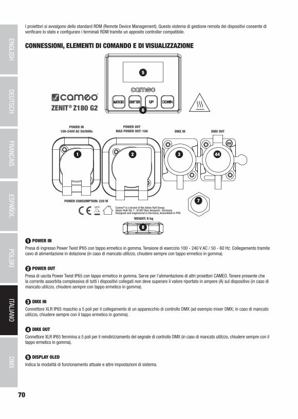
70
DMX
ITALIANOPOLSKI
ESPAÑOLFRANCAIS
DEUTSCHENGLISH
5
1 2 3 44
7
8
6
I proiettori si avvalgono dello standard RDM (Remote Device Management). Questo sistema di gestione remota dei dispositivi consente di verificare lo stato e configurare i terminali RDM tramite un apposito controller compatibile.
CONNESSIONI, ELEMENTI DI COMANDO E DI VISUALIZZAZIONE
1 POWER IN
Presa di ingresso Power Twist IP65 con tappo ermetico in gomma. Tensione di esercizio 100 - 240 V AC / 50 - 60 Hz. Collegamento tramite cavo di alimentazione in dotazione (in caso di mancato utilizzo, chiudere sempre con tappo ermetico in gomma).
2 POWER OUT
Presa di uscita Power Twist IP65 con tappo ermetico in gomma. Serve per l’alimentazione di altri proiettori CAMEO. Tenere presente che la corrente assorbita complessiva di tutti i dispositivi collegati non deve superare il valore riportato in ampere (A) sul dispositivo (in caso di mancato utilizzo, chiudere sempre con tappo ermetico in gomma).
3 DMX IN
Connettore XLR IP65 maschio a 5 poli per il collegamento di un apparecchio di controllo DMX (ad esempio mixer DMX; in caso di mancato utilizzo, chiudere sempre con il tappo ermetico in gomma).
4 DMX OUT
Connettore XLR IP65 femmina a 5 poli per il reindirizzamento del segnale di controllo DMX (in caso di mancato utilizzo, chiudere sempre con il tappo ermetico in gomma).
5 DISPLAY OLED
Indica la modalità di funzionamento attuale e altre impostazioni di sistema.
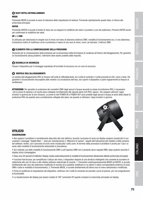
71
DMX
DEUTSC
HFRAN
CAIS
ESPAÑO
LEN
GLISH
ITALIANO
POLSKI
6 TASTI TATTILI RETROILLUMINATI
MODE
Premendo MODE si accede al menu di selezione delle impostazioni di sistema. Premendo ripetutamente questo tasto, si ritorna alla schermata principale.
ENTER
Premendo ENTER si accede al livello di menu da cui eseguire le modifiche dei valori e accedere a uno dei sottomenu. Premere ENTER anche per confermare le modifiche dei valori.
UP e DOWN
Si utilizzano per selezionare le singole voci di menu nel menu di selezione (indirizzo DMX, modalità di funzionamento ecc.) e nei sottomenu. Consentono inoltre di modificare come si preferisce il valore di una voce di menu, come, ad esempio, l’indirizzo DMX.
7 ELEMENTO PER LA COMPENSAZIONE DELLA PRESSIONE
Elemento per la compensazione della pressione per la prevenzione della formazione di condensa all’interno dell’alloggiamento. Per garantire un funzionamento senza problemi, l’elemento deve essere protetto dalle impurità.
8 OCCHIELLO DI SICUREZZA
Fissare il dispositivo per il montaggio sopratesta all’occhiello di sicurezza con un cavo di sicurezza.
9 VENTOLE DELL’ALLOGGIAMENTO
Le ventole dell’alloggiamento IP65 si trovano nell’unità di raffreddamento, tra l’unità di controllo e l’unità provvista di LED, zoom e lente. Per garantire il funzionamento ineccepibile delle ventole e la circolazione dell’aria, non coprire il dispositivo e pulire regolarmente la fessura di ventilazione.
ATTENZIONE: Per garantire la protezione dei connettori DMX dagli spruzzi d’acqua secondo la classe di protezione IP65, è necessario che le prese di ingresso e di uscita siano collegate correttamente alle speciali spine XLR IP65, oppure che vengano utilizzati i tappi ermetici in gomma per la loro chiusura. Le prese di rete POWER IN e POWER OUT sono protette dagli spruzzi d’acqua ai sensi della classe di protezione IP65 sia quando sono correttamente collegate alle spine, sia quando si utilizzano i tappi ermetici in gomma.
9
UTILIZZOOSSERVAZIONI
• Non appena il proiettore è correttamente allacciato alla rete elettrica, durante il processo di avvio sul display vengono visualizzati in suc-cessione i messaggi “Update Wait...” (solo per manutenzione) e “Welcome to Cameo”, seguiti dall’indicazione del modello e della versione del software. Inoltre, con il processo di avvio viene inizializzata l’unità zoom. Al termine della procedura il proiettore è pronto per l’uso e si avvia nella modalità di funzionamento selezionata in precedenza.
• Se è attivata una delle modalità di funzionamento DMX e sull’ingresso DMX non è presente alcun segnale DMX, dopo qualche secondo il display inizia a lampeggiare.
• Dopo circa 30 secondi di inattività il display mostra automaticamente la modalità di funzionamento attualmente attivata (schermata principale).
• Funzione Fast Access: per semplificare l’utilizzo del menu, il dispositivo dispone di una struttura intelligente che consente di accedere di-rettamente alle voci di menu e alle relative sottovoci selezionate di recente. 1. Premendo contemporaneamente MODE ed ENTER, si accede direttamente alla voce del sottomenu modificata di recente ed è possibile modificare in un attimo il valore corrispondente (indirizzo di avvio DMX e tutte le modalità di funzionamento). 2. Premendo MODE, si accede direttamente all’ultima voce di menu selezionata e modificata.
• Prima di modificare le impostazioni del dispositivo, verificare che l’unità di comando sia asciutta e priva di polvere, per non pregiudicarne la funzionalità.
• La visualizzazione del display può essere ruotata di 180° premendo UP quando compare la schermata principale sul display.
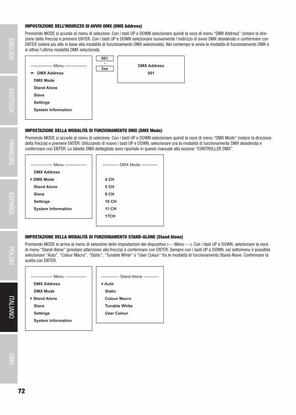
72
DMX
ITALIANOPOLSKI
ESPAÑOLFRANCAIS
DEUTSCHENGLISH
IMPOSTAZIONE DELL’INDIRIZZO DI AVVIO DMX (DMX Address)
Premendo MODE si accede al menu di selezione. Con i tasti UP e DOWN selezionare quindi la voce di menu “DMX Address” (notare la dire-zione della freccia) e premere ENTER. Con i tasti UP e DOWN selezionare nuovamente l’indirizzo di avvio DMX desiderato e confermare con ENTER (valore più alto in base alla modalità di funzionamento DMX selezionata). Nel contempo si avvia la modalità di funzionamento DMX e si attiva l’ultima modalità DMX selezionata.
---------------- Menu ----------------
DMX Address
DMX Mode
Stand Alone
Slave
Settings
System Information
001
5xx- DMX Address
001
IMPOSTAZIONE DELLA MODALITÀ DI FUNZIONAMENTO DMX (DMX Mode)
Premendo MODE si accede al menu di selezione. Con i tasti UP e DOWN selezionare quindi la voce di menu “DMX Mode” (notare la direzione della freccia) e premere ENTER. Utilizzando di nuovo i tasti UP e DOWN, selezionare ora la modalità di funzionamento DMX desiderata e confermare con ENTER. Le tabelle DMX dettagliate sono riportate in questo manuale alla sezione “CONTROLLER DMX”.
---------------- Menu ----------------
DMX Address
DMX Mode
Stand Alone
Slave
Settings
System Information
------------ DMX Mode ------------
4 CH
5 CH
9 CH
10 CH
11 CH
17CH
IMPOSTAZIONE DELLA MODALITÀ DI FUNZIONAMENTO STAND-ALONE (Stand Alone)
Premendo MODE si arriva al menu di selezione delle impostazioni del dispositivo (--- Menu ---). Con i tasti UP e DOWN, selezionare la voce di menu “Stand-Alone” (prestare attenzione alla freccia) e confermare con ENTER. Sempre con i tasti UP e DOWN, nel sottomenu è possibile selezionare “Auto”, “Colour Macro”, “Static”, “Tunable White” o “User Colour” fra le modalità di funzionamento Stand-Alone. Confermare la scelta con ENTER.
---------------- Menu ----------------
DMX Address
DMX Mode
Stand Alone
Slave
Settings
System Information
------------- Stand Alone -----------
Auto
Static
Colour Macro
Tunable White
User Colour
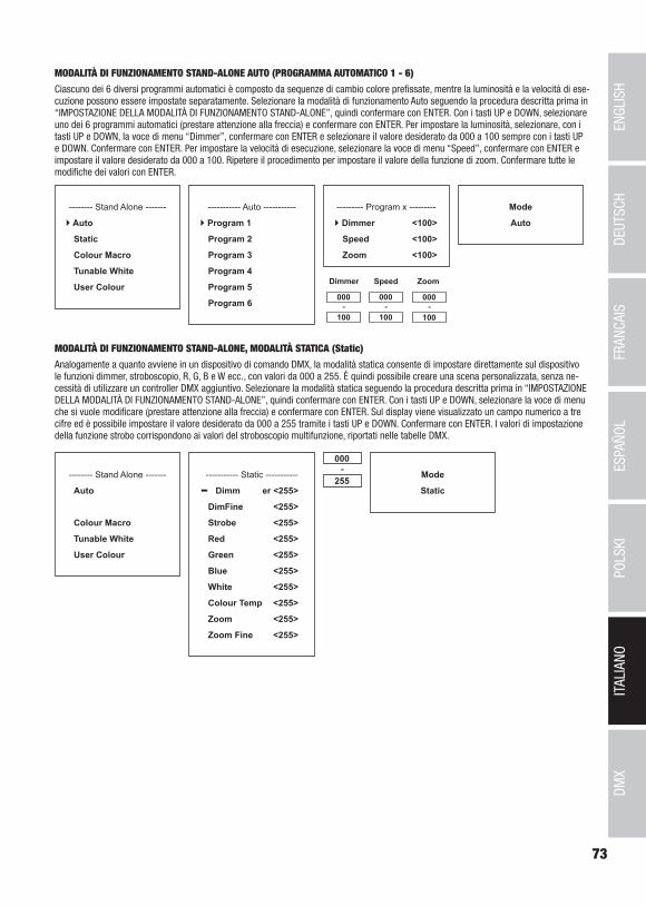
73
DMX
DEUTSC
HFRAN
CAIS
ESPAÑO
LEN
GLISH
ITALIANO
POLSKI
MODALITÀ DI FUNZIONAMENTO STAND-ALONE AUTO (PROGRAMMA AUTOMATICO 1 - 6)
Ciascuno dei 6 diversi programmi automatici è composto da sequenze di cambio colore prefissate, mentre la luminosità e la velocità di ese-cuzione possono essere impostate separatamente. Selezionare la modalità di funzionamento Auto seguendo la procedura descritta prima in “IMPOSTAZIONE DELLA MODALITÀ DI FUNZIONAMENTO STAND-ALONE”, quindi confermare con ENTER. Con i tasti UP e DOWN, selezionare uno dei 6 programmi automatici (prestare attenzione alla freccia) e confermare con ENTER. Per impostare la luminosità, selezionare, con i tasti UP e DOWN, la voce di menu “Dimmer”, confermare con ENTER e selezionare il valore desiderato da 000 a 100 sempre con i tasti UP e DOWN. Confermare con ENTER. Per impostare la velocità di esecuzione, selezionare la voce di menu “Speed”, confermare con ENTER e impostare il valore desiderato da 000 a 100. Ripetere il procedimento per impostare il valore della funzione di zoom. Confermare tutte le modifiche dei valori con ENTER.
Mode
Auto
-------- Stand Alone -------
Auto
Static
Colour Macro
Tunable White
User Colour
----------- Auto -----------
Program 1
Program 2
Program 3
Program 4
Program 5
Program 6
--------- Program x ---------
Dimmer <100>
Speed <100>
Zoom <100>
000
100-
Dimmer Speed
000
100-
MODALITÀ DI FUNZIONAMENTO STAND-ALONE, MODALITÀ STATICA (Static)
Analogamente a quanto avviene in un dispositivo di comando DMX, la modalità statica consente di impostare direttamente sul dispositivo le funzioni dimmer, stroboscopio, R, G, B e W ecc., con valori da 000 a 255. È quindi possibile creare una scena personalizzata, senza ne-cessità di utilizzare un controller DMX aggiuntivo. Selezionare la modalità statica seguendo la procedura descritta prima in “IMPOSTAZIONE DELLA MODALITÀ DI FUNZIONAMENTO STAND-ALONE”, quindi confermare con ENTER. Con i tasti UP e DOWN, selezionare la voce di menu che si vuole modificare (prestare attenzione alla freccia) e confermare con ENTER. Sul display viene visualizzato un campo numerico a tre cifre ed è possibile impostare il valore desiderato da 000 a 255 tramite i tasti UP e DOWN. Confermare con ENTER. I valori di impostazione della funzione strobo corrispondono ai valori del stroboscopio multifunzione, riportati nelle tabelle DMX.
Mode
Static
-------- Stand Alone -------
Auto
Colour Macro
Tunable White
User Colour
----------- Static -----------
Dimm er <255>
DimFine <255>
Strobe <255>
Red <255>
Green <255>
Blue <255>
White <255>
Colour Temp <255>
Zoom <255>
Zoom Fine <255>
000
255-
Zoom
000
100-

74
DMX
ITALIANOPOLSKI
ESPAÑOLFRANCAIS
DEUTSCHENGLISH
MODALITÀ DI FUNZIONAMENTO STAND-ALONE MACRO COLORE (Colour Macro)
Sono disponibili 15 diversi macro colori predefiniti. Selezionare, come descritto in precedenza al punto IMPOSTAZIONE DELLA MODALITÀ DI FUNZIONAMENTO, la voce di menu “Colour Macro” e confermare con ENTER. Con UP e DOWN selezionare ora il colore desiderato come preset (v. freccia) e confermare con ENTER (Colour Off = Blackout). Sul display viene visualizzato un campo numerico a tre cifre ed è possibile impostare la luminosità desiderata da 000 a 100 tramite i tasti UP e DOWN. Confermare con ENTER. L’impostazione della funzione zoom avviene nello stesso modo.
Mode
Colour Macro
------- Stand Alone ------
Auto
Static
Colour Macro
Tunable White
User Colour
----- Colour Macro -----
Colour Off
Red <100>
Amber <100>
Yellow Warm <100>
Yellow <100>
Green <100>
Turquoise <100>
Cyan <100>
000
100-
Blue <100>
Lavender <100>
Mauve <100>
Magenta <100>
Pink <100>
Warm White <100>
White <100>
Cold White <100>
Zoom <100>
MODALITÀ DI FUNZIONAMENTO STAND-ALONE TEMPERATURA DEL COLORE (Tunable White)
La modalità Temperatura del colore consente di impostare la luce direttamente sul dispositivo con una temperatura colore che va dal bianco freddo al bianco caldo (CTC), la luminosità (Dimmer) e la funzione zoom. Selezionare la modalità Temperatura del colore seguendo la procedura descritta prima in “IMPOSTAZIONE DELLA MODALITÀ DI FUNZIONAMENTO STAND-ALONE”, quindi confermare con ENTER. Con i tasti UP e DOWN, selezionare la voce di menu che si vuole modificare (prestare attenzione alla freccia) e confermare con ENTER. Sul display viene visualizzato un campo numerico a tre cifre ed è possibile impostare il valore desiderato tramite i tasti UP e DOWN. Confermare con ENTER.
Mode
Tunable White
------- Stand Alone ------
Auto
Static
Colour Macro
Tunable White
User Colour
----- Tunable White -----
Dimmer <100>
CTC <100>
Zoom <100>
000
100-
MODALITÀ DI FUNZIONAMENTO STAND-ALONE PRESET UTENTE (User Colour)
La modalità di funzionamento stand-alone “Preset utente” consente di salvare la luminosità generale e il mix cromatico di R, G, B e W ecc., direttamente nel dispositivo in quattro preset cromatici individuali. Selezionare la voce di menu “User Colour” seguendo la procedura descritta prima in “IMPOSTAZIONE DELLA MODALITÀ DI FUNZIONAMENTO STAND-ALONE”, quindi confermare con ENTER. Con i tasti UP e DOWN, selezionare ora uno degli spazi di memoria da Colour1 a Colour4, confermare con ENTER e selezionare la voce del sottomenu che si desidera modificare (prestare attenzione alla freccia). Confermare con ENTER. Sul display viene ora visualizzato un campo numerico a tre cifre e con i tasti UP e DOWN è possibile impostare il valore desiderato da 000 a 255. Confermare di nuovo premendo ENTER. I valori di impostazione della funzione strobo corrispondono ai valori del stroboscopio multifunzione, riportati nelle tabelle DMX.
Mode
User Colour
------- Stand Alone ------
Auto
Static
Colour Macro
Tunable White
User Colour
--------- Colour 1 ---------
Dimmer <255>
DimFine <255>
Strobe <255>
Red <255>
Green <255>
Blue <255>
White <255>
Colour Temp <255>
Zoom <255>
Zoom Fine <255>
000
255-------- User Colour -------
Colour 1
Colour 2
Colour 3
Colour 4

75
DMX
DEUTSC
HFRAN
CAIS
ESPAÑO
LEN
GLISH
ITALIANO
POLSKI
MODALITÀ DI FUNZIONAMENTO SLAVE
Premendo MODE si accede al menu di selezione. Con i tasti UP e DOWN, selezionare la voce di menu “Slave” (prestare attenzione alla freccia) e confermare con ENTER. Collegare le unità slave e master (stesso modello) utilizzando un cavo DMX; sull’unità master attivare una delle modalità di funzionamento Stand-Alone (Auto, Static, Colour Macro, Tunable White, User Colour). Ora l’unità slave segue l’unità master. In assenza di un segnale di controllo, i caratteri sul display iniziano a lampeggiare, mentre in presenza del segnale il lampeggio si arresta.
---------------- Menu ----------------
DMX Address
DMX Mode
Stand Alone
Slave
Settings
System Information
Mode
Slave
IMPOSTAZIONI DEL DISPOSITIVO (Settings)
Premendo MODE si accede al menu di selezione. Con i tasti UP e DOWN, selezionare la voce di menu “Settings” (prestare attenzione alla freccia) e confermare con ENTER.
---------------- Menu ----------------
DMX Address
DMX Mode
Stand Alone
Slave
Settings
System Information
Si accede quindi al sottomenu per l’impostazione delle seguenti voci di sottomenu (selezionare con UP e DOWN, confermare con ENTER, modificare il valore o lo stato con UP e DOWN, confermare con ENTER):
Settings (grassetto = impostazione di fabbrica)Display Reverse = rotazione del display On Rotazione del display di 180° (per es. per montaggio
sopratesta)Off Nessuna rotazione del display
Display Backlight = display e illuminazione del pannello di comando
On Sempre accesoOff Disattivazione dopo circa 30 secondi di inattività
DMX Fail = condizione di funzionamento in caso di interruzione del segnale DMX
Hold Mantiene l’ultimo comandoBlackout Blackout attivato
Dimmer Curve = curva del dimmer Linear L’intensità della luce cresce in maniera lineare con il valore DMX
Exponential L’intensità della luce può essere impostata in manie-ra precisa nell’intervallo di valori DMX inferiore e grossolanamente in quello superiore
Logarithmic L’intensità della luce può essere impostata grosso-lanamente nell’intervallo di valori DMX inferiore e in maniera precisa in quello superiore
S-Curve L’intensità della luce può essere impostata in ma-niera precisa nell’intervallo di valori DMX inferiore e superiore e grossolanamente in quello intermedio
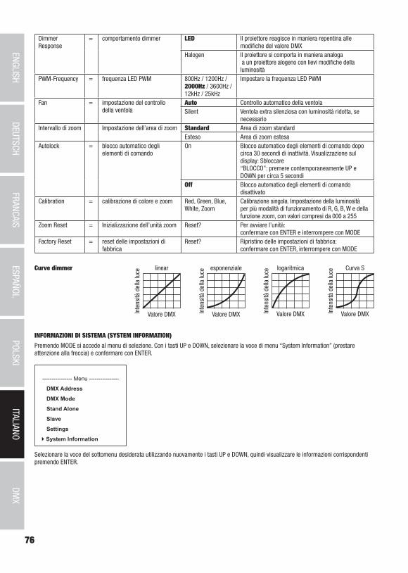
76
DMX
ITALIANOPOLSKI
ESPAÑOLFRANCAIS
DEUTSCHENGLISH
DimmerResponse
= comportamento dimmer LED Il proiettore reagisce in maniera repentina alle modifiche del valore DMX
Halogen Il proiettore si comporta in maniera analoga a un proiettore alogeno con lievi modifiche della luminosità
PWM-Frequency = frequenza LED PWM 800Hz / 1200Hz / 2000Hz / 3600Hz / 12kHz / 25kHz
Impostare la frequenza LED PWM
Fan = impostazione del controllo della ventola
Auto Controllo automatico della ventolaSilent Ventola extra silenziosa con luminosità ridotta, se
necessarioIntervallo di zoom Impostazione dell’area di zoom Standard Area di zoom standard
Esteso Area di zoom estesaAutolock = blocco automatico degli
elementi di comandoOn Blocco automatico degli elementi di comando dopo
circa 30 secondi di inattività. Visualizzazione sul display: Sbloccare “BLOCCO”: premere contemporaneamente UP e DOWN per circa 5 secondi
Off Blocco automatico degli elementi di comando disattivato
Calibration = calibrazione di colore e zoom Red, Green, Blue, White, Zoom
Calibrazione singola. Impostazione della luminosità per più modalità di funzionamento di R, G, B, W e della funzione zoom, con valori compresi da 000 a 255
Zoom Reset = Inizializzazione dell’unità zoom Reset? Per avviare l’unità: confermare con ENTER e interrompere con MODE
Factory Reset = reset delle impostazioni di fabbrica
Reset? Ripristino delle impostazioni di fabbrica: confermare con ENTER, interrompere con MODE
linear
Valore DMXInte
nsità
del
la lu
ce
esponenziale
Valore DMXInte
nsità
del
la lu
ce
logaritmica
Valore DMXInte
nsità
del
la lu
ce Curva S
Valore DMXInte
nsità
del
la lu
ceCurve dimmer
INFORMAZIONI DI SISTEMA (SYSTEM INFORMATION)
Premendo MODE si accede al menu di selezione. Con i tasti UP e DOWN, selezionare la voce di menu “System Information” (prestare attenzione alla freccia) e confermare con ENTER.
---------------- Menu ----------------
DMX Address
DMX Mode
Stand Alone
Slave
Settings
System Information
Selezionare la voce del sottomenu desiderata utilizzando nuovamente i tasti UP e DOWN, quindi visualizzare le informazioni corrispondenti premendo ENTER.

77
DMX
DEUTSC
HFRAN
CAIS
ESPAÑO
LEN
GLISH
ITALIANO
POLSKI
A
B
BC
A
System Information (grassetto = impostazione di fabbrica)
Firmware = visualizzazione del firmware del dispositivo
Main CPU Vx.xx
Temperature = visualizzazione della temperatura dell’unità LED
LED LED TEMP xxxC / xxxF
Celsius/Fahrenheit Unit Celsius (= indicazione in gradi Celsius)
Unit Fahrenheit (= indicazione in gradi Fahrenheit)
Operation Hours = visualizzazione del tempo di funzio-namento
OpTime xxxx:xxh Visualizzazione del tempo di funziona-mento complessivo in ore e minuti
FUNZIONE DI BLOCCO MANUALEL’opzione manuale che consente di evitare l’utilizzo non autorizzato o l’attivazione involontaria del proiettore (vedi “Settings” -> “Autolock”) può essere applicata anche automaticamente. Tenere premuti contemporaneamente i tasti UP e DOWN per circa 5 secondi. Verrà quindi visualizzata sul display la scritta “LOCEKD” permanente e non sarà più possibile modificare le impostazioni del proiettore con i tasti. Per rimuovere il blocco, tenere premuti contemporaneamente i tasti UP e DOWN per circa 5 secondi. La schermata sul display visualizzerà le informazioni mostrate in precedenza.
INSTALLAZIONE E MONTAGGIOGrazie alla staffa doppia e ai piedini in plastica integrati, il proiettore può essere collocato in un punto adatto su una superficie piana. Il mon-taggio a una traversa viene effettuato o tramite il codolo TV da 16 mm a incasso (A, adatto per Adam Hall Super Clamp) o tramite una staffa omega da fissare alla staffa del dispositivo (B). Appositi morsetti per traverse e staffa omega (cod. art. CLOMEGABRACKET1) sono disponibili gratuitamente, Collegare saldamente il tutto e fissare il proiettore con un cavo di sicurezza idoneo nella posizione prevista (C).
Importanti indicazioni sulla sicurezza:il montaggio sopratesta richiede una vasta esperienza, incluso il calcolo dei valori limite del carico di lavoro, il materiale di installazione utilizzato e la verifica periodica della sicurezza di tutti i materiali di installazione e dei proiettori. Se non si dispone di queste qualifiche non tentare di effettuare da soli l’installazione, ma ricorrere all’ausilio di aziende professionali.
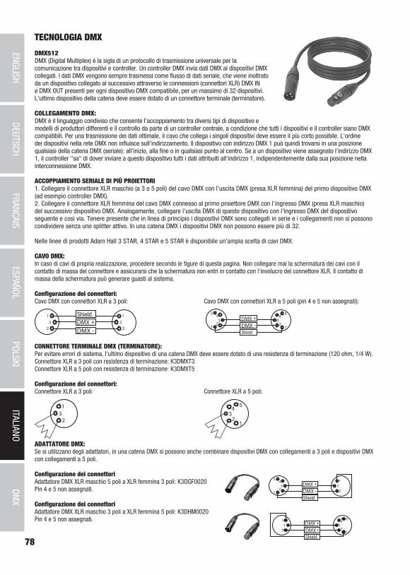
78
DMX
ITALIANOPOLSKI
ESPAÑOLFRANCAIS
DEUTSCHENGLISH
TECNOLOGIA DMX
DMX512DMX (Digital Multiplex) è la sigla di un protocollo di trasmissione universale per la comunicazione tra dispositivi e controller. Un controller DMX invia dati DMX ai dispositivi DMX collegati. I dati DMX vengono sempre trasmessi come flusso di dati seriale, che viene inoltrato da un dispositivo collegato al successivo attraverso le connessioni (connettori XLR) DMX IN e DMX OUT presenti per ogni dispositivo DMX compatibile, per un massimo di 32 dispositivi. L'ultimo dispositivo della catena deve essere dotato di un connettore terminale (terminatore).
COLLEGAMENTO DMX:DMX è il linguaggio condiviso che consente l'accoppiamento tra diversi tipi di dispositivo e modelli di produttori differenti e il controllo da parte di un controller centrale, a condizione che tutti i dispositivi e il controller siano DMX compatibili. Per una trasmissione dei dati ottimale, il cavo che collega i singoli dispositivi deve essere il più corto possibile. L'ordine dei dispositivi nella rete DMX non influisce sull'indirizzamento. Il dispositivo con indirizzo DMX 1 può quindi trovarsi in una posizione qualsiasi della catena DMX (seriale): all'inizio, alla fine o in qualsiasi punto al centro. Se a un dispositivo viene assegnato l'indirizzo DMX 1, il controller "sa" di dover inviare a questo dispositivo tutti i dati attribuiti all'indirizzo 1, indipendentemente dalla sua posizione nella interconnessione DMX.
ACCOPPIAMENTO SERIALE DI PIÙ PROIETTORI1. Collegare il connettore XLR maschio (a 3 o 5 poli) del cavo DMX con l'uscita DMX (presa XLR femmina) del primo dispositivo DMX (ad esempio controller DMX).2. Collegare il connettore XLR femmina del cavo DMX connesso al primo proiettore DMX con l'ingresso DMX (presa XLR maschio) del successivo dispositivo DMX. Analogamente, collegare l'uscita DMX di questo dispositivo con l'ingresso DMX del dispositivo seguente e così via. Tenere presente che in linea di principio i dispositivi DMX sono collegati in serie e i collegamenti non si possono condividere senza uno splitter attivo. In una catena DMX i dispositivi DMX non possono essere più di 32.
Nelle linee di prodotti Adam Hall 3 STAR, 4 STAR e 5 STAR è disponibile un'ampia scelta di cavi DMX.
CAVO DMX:In caso di cavi di propria realizzazione, procedere secondo le figure di questa pagina. Non collegare mai la schermatura dei cavi con il contatto di massa del connettore e assicurarsi che la schermatura non entri in contatto con l'involucro del connettore XLR. Il contatto di massa della schermatura può generare guasti al sistema.
Configurazione dei connettori:Cavo DMX con connettori XLR a 3 poli: Cavo DMX con connettori XLR a 5 poli (pin 4 e 5 non assegnati):
Shield
23
1
23
1
123
45
12
34
5
Shield
CONNETTORE TERMINALE DMX (TERMINATORE):Per evitare errori di sistema, l'ultimo dispositivo di una catena DMX deve essere dotato di una resistenza di terminazione (120 ohm, 1/4 W).Connettore XLR a 3 poli con resistenza di terminazione: K3DMXT3Connettore XLR a 5 poli con resistenza di terminazione: K3DMXT5
Configurazione dei connettori:Connettore XLR a 3 poli: Connettore XLR a 5 poli:
23
1
12
34
5
ADATTATORE DMX:Se si utilizzano degli adattatori, in una catena DMX si possono anche combinare dispositivi DMX con collegamenti a 3 poli e dispositivi DMX con collegamenti a 5 poli.
Configurazione dei connettoriAdattatore DMX XLR maschio 5 poli a XLR femmina 3 poli: K3DGF0020Pin 4 e 5 non assegnati.
Configurazione dei connettoriAdattatore DMX XLR maschio 3 poli a XLR femmina 5 poli: K3DHM0020Pin 4 e 5 non assegnati.

79
DMX
DEUTSC
HFRAN
CAIS
ESPAÑO
LEN
GLISH
ITALIANO
POLSKI
Numero articolo: CLZZ180G2
Tipologia di prodotto: Wash Light a LED
Tipo: Proiettore da esterni
Spettro cromatico LED: RGBW
Numero di LED: 1
Tipo di LED: COB da 180W
Frequenza LED PWM: 800Hz, 1200Hz, 2000Hz, 3600Hz, 12kHz, 25kHz (regolabile)
Angolo di emissione: 10° - 40°
Ingresso DMX: XLR maschio a 5 poli, IP65
Uscita DMX: XLR femmina a 5 poli, IP65
Modalità DMX: 3 canali, 4 canali, 5 canali, 9 canali, 10 canali, 11 canali, 17 canali
Funzioni DMX: Dimmer, Dimmer Fine, RGBW, RGBW Fine, Stroboscopio, Correzione della temperatura del colore, Macro colore, Cambiamenti colore, Dissolvenza colori, Zoom, Zoom Fine, Comportamento dimmer, altre impostazioni di sistema
Funzioni stand-alone: Macro colore, Programmi automatici, Modalità statica, Stroboscopio, User Colour, Tunable White, Funzionamento master/slave
Impostazioni di sistema: Rotazione del display di 180°, illuminazione del display, DMX Fail, curve dimmer, comportamento dimmer, calibrazione dei colori, funzione di blocco del display, frequenza LED PWM, zoom reset, Factory Reset, controllo della ventola
Controller: DMX512, compatibile con RDM
Elementi di comando: MODE, ENTER, UP, DOWN (tasti touch)
Elementi di visualizzazione: Display OLED
Tensione di esercizio: 100 - 240 V CA, 50 - 60 Hz
Potenza assorbita: 220W
Intensità di illuminazione (a 1 m): 56790lx (narrow)
Flusso luminoso (RGBW): 4900lm
Collegamento alimentazione elettrica:
Ingresso e uscita, connettori Power Twist IP65 (uscita max. 10 A)
Temperatura ambiente (in esercizio):
-15 °C - +45 °C
Materiale cassa: Metallo
Colore cassa: nero
Raffreddamento alloggiamento: Ventola IP65 con regolazione di temperatura
Grado di protezione: IP65
Ingombro (L x H x P, senza staffe di montaggio):
240 x 240 x 254mm
Peso: 8,0 kg
Altre caratteristiche: Cavo di alimentazione da 1 m con spina Power Twist IP65 e staffa di supporto/montaggio in dota-zione. Codolo TV da 16 mm integrato. Paraluce e staffa omega disponibili come optional
DATI TECNICI

80
DMX
ITALIANOPOLSKI
ESPAÑOLFRANCAIS
DEUTSCHENGLISH
DICHIARAZIONI DEL PRODUTTORE
MANUFACTURER’S WARRANTY & LIMITATION OF LIABILITY Le nostre attuali condizioni di garanzia e la limitazione di responsabilità sono consultabili alla pagina: https://cdn-shop.adamhall.com/media/pdf/MANUFACTURERS-DECLARATIONS_CAMEO.pdf. In caso di assistenza, rivolgersi a Adam Hall GmbH, Adam-Hall-Str. 1, 61267 Neu Anspach / E-mail [email protected] / +49 (0)6081 / 9419-0.
CORRETTO SMALTIMENTO DEL PRODOTTO(In vigore nell‘Unione Europea e in altri Paesi europei in cui si attui la raccolta differenziata) Questo simbolo apposto sul prodotto o sui relativi documenti indica che, per evitare danni all‘ambiente e alle persone causati da uno smaltimento incontrollato dei rifiuti,
alla fine del suo ciclo di vita l‘apparecchio non deve essere smaltito insieme ai normali rifiuti domestici. Il prodotto deve quindi essere smaltito separatamente da altri rifiuti e riciclato nell‘ottica dell‘incentivazione di cicli economici sostenibili. I clienti privati possono richiedere informazioni sulle possibilità di smaltimento ecosostenibile al rivenditore presso il quale è stato acquistato il prodotto o presso le autorità regionali competenti. I clienti aziendali devono invece contattare il proprio fornitore e controllare le eventuali condizioni contrattuali inerenti allo smaltimento degli apparecchi. Questo prodotto non deve essere smaltito assieme ad altri rifiuti industriali.
Conformità CECon la presente Adam Hall GmbH dichiara che questo prodotto soddisfa le seguenti direttive (ove pertinente):Direttiva R&TTE (1999/5/CE) e RED (2014/53/UE) da giugno 2017Direttiva bassa tensione (2014/35/CE)Direttiva CEM (2014/30/UE)RoHS (2011/65/UE)La dichiarazione di conformità completa è reperibile al sito www.adamhall.com. Per ulteriori informazioni è inoltre possibile scrivere a [email protected].

81
DMX
DEUTSC
HFRAN
CAIS
ESPAÑO
LEN
GLISH
ITALIANO
POLSKI
DMX CONTROL / DMX STEUERUNG / PILOTAGE DMX / CONTROL DMX / STEROWANIE DMX / CONTROLLO DMX
3CH ModeCh. Function Values Sub-Group1 Dimmer 000 - 255 0% to 100% Dimmer2 Colour Temperature 000 - 255 7200K - 3200K Colour Temperature3 Zoom 000 - 255 narrow to wide Zoom
4CH ModeCh. Function Values Sub-Group1 Dimmer 000 - 255 0% to 100% Dimmer
2 Strobe functions
000 - 005 Strobe open
Multifunctional Strobe
006 - 010 Strobe closed011 - 033 Pulse Random, slow -> fast034 - 056 Ramp up Random, slow -> fast057 - 079 Ramp down Random, slow -> fast080 - 102 Random Strobe Effect, slow -> fast
103 - 127 Strobe Break Effect, 5s…..1s (Short burst with break)
128 - 250 Strobe slow -> fast <1Hz - 20Hz251 - 255 Strobe open
3Colour Macro
& Colour Jumping & Colour Fading
000 - 005 Colour off
Colour Macro
006 - 013 Red014 - 021 Amber022 - 029 Yellow warm030 - 037 Yellow038 - 045 Green046 - 053 Turquoise054 - 061 Cyan062 - 069 Blue070 - 077 Lavender078 - 085 Mauve086 - 093 Magenta094 - 101 Pink102 - 109 Warm White110 - 117 White118 - 125 Cold White126 - 127 Colour Jumping Stop
128 - 191 Colour Jumping Speed slow -> fast / Colour 1 -> 12
192 - 255 Colour Fading Speed slow -> fast / Colour 1 -> 12
4 Zoom 000 - 255 narrow to wide Zoom
5CH ModeCh. Function Values Sub-Group1 Red 000 - 255 0% to 100% Red2 Green 000 - 255 0% to 100% Green3 Blue 000 - 255 0% to 100% Blue4 White 000 - 255 0% to 100% White5 Zoom 000 - 255 narrow to wide Zoom

82
DMX
ITALIANOPOLSKI
ESPAÑOLFRANCAIS
DEUTSCHENGLISH
9CH ModeCh. Function Values Sub-Group1 Dimmer 000 - 255 0% to 100% Dimmer
2 Strobe Functions
000 - 005 Strobe open
Multifunctional Strobe
006 - 010 Strobe closed011 - 033 Pulse Random, slow -> fast034 - 056 Ramp up Random, slow -> fast057 - 079 Ramp down Random, slow -> fast080 - 102 Random Strobe Effect, slow -> fast
103 - 127 Strobe Break Effect, 5s…..1s (Short burst with break)
128 - 250 Strobe slow -> fast <1Hz - 20Hz251 - 255 Strobe open
3 Red 000 - 255 0% to 100% Red4 Green 000 - 255 0% to 100% Green5 Blue 000 - 255 0% to 100% Blue6 White 000 - 255 0% to 100% White
7
Colour Macro & Colour Jumping & Colour Fading
(overrides RGBW)
000 - 005 Colour off
Colour Macro
006 - 013 Red014 - 021 Amber022 - 029 Yellow warm030 - 037 Yellow038 - 045 Green046 - 053 Turquoise054 - 061 Cyan062 - 069 Blue070 - 077 Lavender078 - 085 Mauve086 - 093 Magenta094 - 101 Pink102 - 109 Warm White110 - 117 White118 - 125 Cold White126 - 127 Colour Jumping Stop
128 - 191 Colour Jumping Speed slow -> fast / Colour 1 -> 12
192 - 255 Colour Fading Speed slow -> fast / Colour 1 -> 12
8 Zoom 000 - 255 narrow to wide Zoom
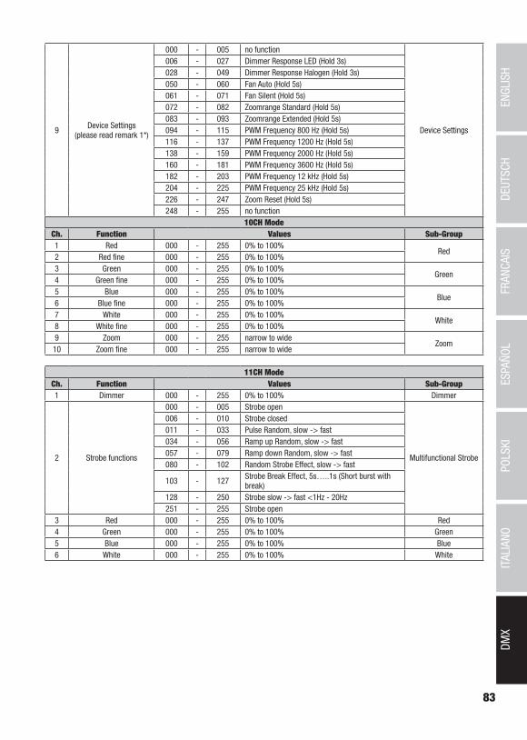
83
DMX
DEUTSC
HFRAN
CAIS
ESPAÑO
LEN
GLISH
ITALIANO
POLSKI
9 Device Settings (please read remark 1*)
000 - 005 no function
Device Settings
006 - 027 Dimmer Response LED (Hold 3s)028 - 049 Dimmer Response Halogen (Hold 3s)050 - 060 Fan Auto (Hold 5s)061 - 071 Fan Silent (Hold 5s)072 - 082 Zoomrange Standard (Hold 5s)083 - 093 Zoomrange Extended (Hold 5s)094 - 115 PWM Frequency 800 Hz (Hold 5s)116 - 137 PWM Frequency 1200 Hz (Hold 5s)138 - 159 PWM Frequency 2000 Hz (Hold 5s)160 - 181 PWM Frequency 3600 Hz (Hold 5s)182 - 203 PWM Frequency 12 kHz (Hold 5s)204 - 225 PWM Frequency 25 kHz (Hold 5s)226 - 247 Zoom Reset (Hold 5s)248 - 255 no function
10CH ModeCh. Function Values Sub-Group1 Red 000 - 255 0% to 100%
Red2 Red fine 000 - 255 0% to 100% 3 Green 000 - 255 0% to 100%
Green4 Green fine 000 - 255 0% to 100% 5 Blue 000 - 255 0% to 100%
Blue6 Blue fine 000 - 255 0% to 100% 7 White 000 - 255 0% to 100%
White8 White fine 000 - 255 0% to 100% 9 Zoom 000 - 255 narrow to wide
Zoom10 Zoom fine 000 - 255 narrow to wide
11CH ModeCh. Function Values Sub-Group1 Dimmer 000 - 255 0% to 100% Dimmer
2 Strobe functions
000 - 005 Strobe open
Multifunctional Strobe
006 - 010 Strobe closed011 - 033 Pulse Random, slow -> fast034 - 056 Ramp up Random, slow -> fast057 - 079 Ramp down Random, slow -> fast080 - 102 Random Strobe Effect, slow -> fast
103 - 127 Strobe Break Effect, 5s…..1s (Short burst with break)
128 - 250 Strobe slow -> fast <1Hz - 20Hz251 - 255 Strobe open
3 Red 000 - 255 0% to 100% Red4 Green 000 - 255 0% to 100% Green5 Blue 000 - 255 0% to 100% Blue6 White 000 - 255 0% to 100% White

84
DMX
ITALIANOPOLSKI
ESPAÑOLFRANCAIS
DEUTSCHENGLISH
7
Colour Macro & Colour Jumping & Colour Fading
(overrides RGBW)
000 - 005 Colour off
Colour Macro
006 - 013 Red014 - 021 Amber022 - 029 Yellow warm030 - 037 Yellow038 - 045 Green046 - 053 Turquoise054 - 061 Cyan062 - 069 Blue070 - 077 Lavender078 - 085 Mauve086 - 093 Magenta094 - 101 Pink102 - 109 Warm White110 - 117 White118 - 125 Cold White126 - 127 Colour Jumping Stop
128 - 191 Colour Jumping Speed slow -> fast / Colour 1 -> 12
192 - 255 Colour Fading Speed slow -> fast / Colour 1 -> 12
8
Colour Temperature Correction
(affects RGBW and Colour Macros)
000 - 005 offColour Temperature
Correction006 - 255cold -> warm
9 Zoom 000 - 255 narrow to wide Zoom
10 Set Dimmer Curve
000 - 005 no function
Set Dimmer Curve006 - 063 Linear Dimmer Curve064 - 127 Exponential128 - 191 Logarithmic 192 - 255 S-Curve Dimmer Curve
11 Device Settings (please read remark 1*)
000 - 005 no function
Device Settings
006 - 027 Dimmer Response LED (Hold 3s)028 - 049 Dimmer Response Halogen (Hold 3s)050 - 060 Fan Auto (Hold 5s)061 - 071 Fan Silent (Hold 5s)072 - 082 Zoomrange Standard (Hold 5s)083 - 093 Zoomrange Extended (Hold 5s)094 - 115 PWM Frequency 800 Hz (Hold 5s)116 - 137 PWM Frequency 1200 Hz (Hold 5s)138 - 159 PWM Frequency 2000 Hz (Hold 5s)160 - 181 PWM Frequency 3600 Hz (Hold 5s)182 - 203 PWM Frequency 12 kHz (Hold 5s)204 - 225 PWM Frequency 25 kHz (Hold 5s)226 - 247 Zoom Reset (Hold 5s)248 - 255 no function
17CH ModeCh. Function Values Sub-Group1 Dimmer 000 - 255 0% to 100%
Dimmer2 Dimmer fine 000 - 255 0% to 100%
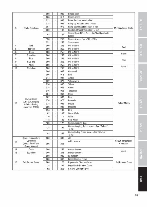
85
DMX
DEUTSC
HFRAN
CAIS
ESPAÑO
LEN
GLISH
ITALIANO
POLSKI
3 Strobe Functions
000 - 005 Strobe open
Multifunctional Strobe
006 - 010 Strobe closed011 - 033 Pulse Random, slow -> fast034 - 056 Ramp up Random, slow -> fast057 - 079 Ramp down Random, slow -> fast080 - 102 Random Strobe Effect, slow -> fast
103 - 127 Strobe Break Effect, 5s…..1s (Short burst with break)
128 - 250 Strobe slow -> fast <1Hz - 20Hz251 - 255 Strobe open
4 Red 000 - 255 0% to 100% Red
5 Red fine 000 - 255 0% to 100% 6 Green 000 - 255 0% to 100%
Green7 Green fine 000 - 255 0% to 100% 8 Blue 000 - 255 0% to 100%
Blue9 Blue fine 000 - 255 0% to 100% 10 White 000 - 255 0% to 100%
White11 White fine 000 - 255 0% to 100%
12
Colour Macro & Colour Jumping & Colour Fading
(overrides RGBW)
000 - 005 Colour off
Colour Macro
006 - 013 Red014 - 021 Amber022 - 029 Yellow warm030 - 037 Yellow038 - 045 Green046 - 053 Turquoise054 - 061 Cyan062 - 069 Blue070 - 077 Lavender078 - 085 Mauve086 - 093 Magenta094 - 101 Pink102 - 109 Warm White110 - 117 White118 - 125 Cold White126 - 127 Colour Jumping Stop
128 - 191 Colour Jumping Speed slow -> fast / Colour 1 -> 12
192 - 255 Colour Fading Speed slow -> fast / Colour 1 -> 12
13
Colour Temperature Correction
(affects RGBW and Colour Macros)
000 - 005 offColour Temperature
Correction006 - 255cold -> warm
14 Zoom 000 - 255 narrow to wideZoom
15 Zoom fine 000 - 255 narrow to wide
16 Set Dimmer Curve
000 005 no function
Set Dimmer Curve006 - 063 Linear Dimmer Curve064 - 127 Exponential Dimmer Curve128 - 191 Logarithmic Dimmer Curve192 - 255 S-Curve Dimmer Curve

86
DMX
ITALIANOPOLSKI
ESPAÑOLFRANCAIS
DEUTSCHENGLISH
17 Device Settings (please read remark 1*)
000 - 005 no function
Device Settings
006 - 027 Dimmer Response LED (Hold 3s)028 - 049 Dimmer Response Halogen (Hold 3s)050 - 060 Fan Auto (Hold 5s)061 - 071 Fan Silent (Hold 5s)072 - 082 Zoomrange Standard (Hold 5s)083 - 093 Zoomrange Extended (Hold 5s)094 - 115 PWM Frequency 800 Hz (Hold 5s)116 - 137 PWM Frequency 1200 Hz (Hold 5s)138 - 159 PWM Frequency 2000 Hz (Hold 5s)160 - 181 PWM Frequency 3600 Hz (Hold 5s)182 - 203 PWM Frequency 12 kHz (Hold 5s)204 - 225 PWM Frequency 25 kHz (Hold 5s)226 - 247 Zoom Reset (Hold 5s)248 - 255 no function
EN: (1*) After the adjustments have been made, set the value to 000 to avoid disturbance by endless function call.DE: (1*) Nachdem die Einstellungen vorgenommen wurden, stellen Sie den Wert auf 000 ein, um Störungen durch endlosen Funktionsaufruf zu vermeiden.FR: (1*) Une fois les ajustements effectués, réglez la valeur sur 000 pour éviter les perturbations par appel de fonction sans fin.ES: (1*) Después de realizar los ajustes, establezca el valor en 000 para evitar perturbaciones mediante una llamada de función sin fin.PL: (1*) Po dokonaniu ustawień ustaw wartość na 000, aby uniknąć zakłóceń przez niekończące się wywołanie funkcji.IT: (1*) Dopo aver effettuato le regolazioni, impostare il valore su 000 per evitare disturbi causati da una chiamata a funzione infinita.


CAMEOLIGHT.COM
Adam Hall GmbH | Adam-Hall-Str. 1 | 61267 Neu-Anspach | GermanyPhone: +49 6081 9419-0 | adamhall.com REV: 02