zentri amw006 / amw106 data sheet · broadcom single band 2.4ghz ieee 802.11b/g/n 1x1 wi-fi...
TRANSCRIPT

Zentri AMW006 / AMW106 Data Sheet

AMWx06 Datasheet
ADS-MWx06-109R AMWx06 Datasheet Page |ii © 2014-2017 Zentri http://www.zentri.com May 18, 2017
Disclaimer
While the information provided in this document is believed to be accurate, it is under development and Zentri reserves the right to make changes without further notice to the product described herein to improve reliability, function, or design, and makes no guarantee or warranty concerning the accuracy of said information, nor shall it be responsible for any loss or damage of whatever nature resulting from the use of, or reliance upon, such information. Zentri makes no warranties of any kind, whether express, implied or arising by custom or course of trade or performance, and specifically disclaims the implied warranties of title, non-infringement, merchantability, or fitness for a particular purpose.
No part of this document may be copied, reproduced, stored in a retrieval system, or transmitted, in any form or by any means, electronic, mechanical, photographic, or otherwise, or used as the basis for manufacture or sale of any items without the prior written consent of Zentri.
Trademarks
Zentri and the Zentri logo are trademarks of Zentri. Other trademarks in this document belong to their respective owners.
© 2014-2017 Zentri.
All rights reserved.
Document Number: ADS-MWx06-109R
Release Date: May 18, 2017
Contact
https://www.zentri.com/contact-us/
About this User Guide
This document provides information on the AMWx06 802.11b/g/n Wi-Fi networking module from Zentri.
Modules covered by this datasheet include:
AMWx06 Rev 6
Further information about ZentriOS is available from:
http://docs.zentri.com
Organization
This document is organized into the following sections:
1 General Description .............................................. 1
2 Block Diagram ....................................................... 2
3 Electrical Specifications ......................................... 3
4 WLAN RF Specifications......................................... 5
5 Pinout and Signal Descriptions .............................. 7
6 Design Guidelines .................................................. 9
7 Regulatory Certification ...................................... 15
8 Packaging, Handling and Storage, RoHS ............. 22
9 Ordering Information .......................................... 25
10 Revision History & Glossary ......................... 26
11 References ................................................... 27

AMWx06 Datasheet
ADS-MWx06-109R AMWx06 Datasheet Page |iii © 2014-2017 Zentri http://www.zentri.com May 18, 2017
Features Self-contained ultra-low power Wi-Fi module with
microcontroller and support for ZentriOS-W firmware (AMW006/AMW106) and ZentriOS-WZ firmware (AMW106), including industry standard SSL/TLS secure TCP/IP network stack.
Integrated SPI-serial flash for software upgrades and user accessible read/write file system
Wi-Fi
Broadcom single band 2.4GHz IEEE 802.11b/g/n 1x1 Wi-Fi transceiver
Includes support for all Wi-Fi security modes including Open, WEP, WPA, and WPA2-PSK
Microprocessor
ARM Cortex® M4 based microprocessor
AMW006: operates up to 84MHz core frequency
AMW106: operates up to 100MHz core frequency
RAM
AMW006: 96 KB
AMW106: 128 KB Interfaces*
UART: 2 x 4-wire up to 10.5Mbit/s
SPI : SPI-Master (42Mbit/s), SPI-Slave (21Mbit/s)
GPIO: Up to 21 GPIOs (overlaid with peripherals)
A/D converter: 9 channel input, 12-bit resolution, 2.4MSPS sampling in single-shot or scan mode
PWM: Up to 14 PWM outputs
Wake-up: Wake pin for ultra-low power operation
Two external antennas for diversity and improved range
*Some interfaces share module pins
Operational & Radio Single operating voltage : 3.3V (typical)
All I/O pins are +5V tolerant
Operational Temperature Range: -30°C to +85°C
Size : 20.3 x 15.2 x 2.7mm (0.80” x 0.60” x 0.11”)
Weight : 0.07 oz (2g)
Current consumption @ 3.3V, 25°C - VBAT : 0.97µA (with 32k RTC) - Standby : 2.8µA (3.8uA with 32k RTC) - Stop : 10µA with RAM retention (113µs wake) - Wi-Fi Powersave : 0.77mA (DTIM = 3) - Active receive : 5.7mA @ 1Mbit/s UDP
Active transmit : 11.4mA @ 1Mbit/s UDP
Maximum RF transmit power - 802.11b/g : +18 dBm - 802.11n : +14 dBm
Minimum Receive sensitivity - 802.11b/g : -94 dBm - 802.11n : -86 dBm
Sustained TCP throughput : 10 Mbit/s
Applications Industrial, M2M and Home Automation
- Environmental monitoring - Energy monitoring - Wireless sensing, remote data logging - HVAC, power, light, & thermostat control - Appliance control
Security - Cameras, Doors/Window monitoring - Alarms, Smoke Detectors - Door and entry control
Health & Fitness - Fitness Equipment - Home health monitoring e.g. weight scales
Consumer - Audio, Toys, Robots

AMWx06 Datasheet
ADS-MWx06-109R AMWx06 Datasheet Page |iv © 2014-2017 Zentri http://www.zentri.com May 18, 2017
ZentriOS-W/ZentriOS-WZ Firmware Features
The ZentriOS-W/ZentriOS-WZ firmware supplied with the AMWx06 provides a wide range of features beyond the underlying hardware, and supports application development via its command API.
For complete documentation of ZentriOS-W, see:
https://docs.zentri.com/zentrios/w/latest/
The AMW106 supports ZentriOS-WZ firmware, which adds support for developing ZentriOS apps (ZAPs).
For complete documentation of ZentriOS-WZ, see:
https://docs.zentri.com/zentrios/wz/latest/
Software APIs
ZentriOS-W command API
ZentriOS-WZ command API
ZentriOS-WZ SDK and native API
Interfaces
Serial (UART, remote terminal)
SoftAP and WLAN client (concurrent)
I2C master
SPI master
Servers
TCP/TLS, UDP, HTTP(S), DHCP, DNS
HTTP(S) Server with RESTful API and Websockets
Fully customizable mobile responsive Web application with JavaScript and Python libraries
Clients
TCP/TLS, UDP, NTP, Secure-SMTP, DHCP, DNS
HTTP(S) client
Websocket client
Setup
Multiple Wi-Fi setup options, including via serial command and Web setup with SoftAP
Peripherals and Sensors
GPIOs for control, indication and monitoring
I2C-master API for interfacing to external peripherals
SPI-master API for interfacing to external peripherals
Automated broadcast and streaming of sensor data
Local caching of sensor data
Update and Recovery
Wireless OTA (Over-the-Air) update to remote manage firmware using the Zentri DMS (Device Management Service)
System Management
System configuration and monitoring via setting and getting a wide range of variables
Configurable power states Sleep/wake timers
File System
Read/write file system with appendable log files
Storage of large files
Optional additional bulk serial flash
HTTP download to file system, HTTP upload from file system

AMWx06 Datasheet
ADS-MWx06-109R AMWx06 Datasheet Page |v © 2014-2017 Zentri http://www.zentri.com May 18, 2017
Contents 1 General Description .............................................. 1
2 Block Diagram ....................................................... 2
3 Electrical Specifications ......................................... 3
3.1 Absolute Maximum Ratings ................... 3
3.2 Recommended Operating Conditions ... 3
3.2.1 DC Operating Conditions ................ 3
3.2.2 Environmental Conditions .............. 4
3.3 Power Consumption .............................. 4
3.4 32kHz Crystal ......................................... 4
4 WLAN RF Specifications ........................................ 5
4.1 Summary WLAN Specifications .............. 5
4.2 WLAN Receiver Specifications ............... 5
4.3 WLAN Transmitter Specifications .......... 6
5 Pinout and Signal Descriptions ............................. 7
5.1 Pinout ..................................................... 7
5.2 Pin Description ....................................... 7
6 Design Guidelines .................................................. 9
6.1 Recommended PCB Footprint ............... 9
6.2 Routing Recommendations ................. 10
6.3 Soldering Information .......................... 11
6.4 Module Photograph ............................. 12
6.5 External Antennas ................................ 12
6.5.1 PCB Trace Antenna ....................... 12
6.5.2 Wire Antenna ............................... 12
1.1.1 Chip Antenna ................................ 12
6.5.3 Monopole Antenna ...................... 13
6.6 Application Examples ........................... 14
6.6.1 Operation using ZentriOS ............. 14
7 Regulatory Certification ...................................... 15
7.1 United States ....................................... 15
7.1.1 Labeling and User Information Requirements ............................................. 15
7.1.2 RF Exposure .................................. 16
7.1.3 Approved External Antenna Types 16
7.1.4 Further Information ..................... 16
7.2 Canada ................................................. 17
7.2.1 Labeling and User Information Requirements.............................................. 17
7.2.2 External Antenna Types................ 18
7.2.3 Further Information ..................... 18
7.3 Europe .................................................. 18
7.3.1 Labeling and User Information Requirements.............................................. 19
7.3.1 External Antenna Requirements .. 19
7.3.2 Further Information ..................... 19
7.4 Australia ............................................... 20
7.4.1 External Antenna Requirements .. 20
7.4.2 Further Information ..................... 20
7.5 New Zealand ........................................ 20
7.5.1 External Antenna Requirements .. 20
7.5.2 Further Information ..................... 21
7.6 Japan .................................................... 21
8 Packaging, Handling and Storage, RoHS ............. 22
8.1 Packaging ............................................. 22
8.2 Handling & Storage .............................. 22
8.3 RoHS Directive ..................................... 22
8.4 Tape and Reel Specifications ............... 23
8.5 Cut Tape and Reel Quantity ................. 24
9 Ordering Information .......................................... 25
9.1 Ordering an Unspecified ZentriOS Version 25
9.2 Ordering a Specific ZentriOS Version or a Custom Firmware Version .................................. 25
10 Revision History & Glossary ......................... 26
10.1 Revision History ................................... 26
10.2 Glossary ................................................ 26
11 References ................................................... 27
AMWx06 Datasheet
ADS-MWx06-109R AMWx06 Datasheet Page |vi © 2014-2017 Zentri http://www.zentri.com May 18, 2017

General Description
ADS-MWx06-109R AMWx06 Datasheet Page |1 © 2014-2017 Zentri http://www.zentri.com May 18, 2017
1 General DescriptionThe AMW006 and AMW106 modules from Zentri combine a microcontroller with a BCM43362 Wi-Fi device to provide an advanced stand-alone Wi-Fi and networking solution.
The term AMWx06 refers to both modules.
An integrated module avoids difficult RF layout and enables designers to rapidly embed Wi-Fi and secure networking functionality into virtually any device.
The ZentriOS serial-to-Wi-Fi application, pre-programmed into all modules, may be used to fast-track module integration into end-products.
With dimensions of just 20.3mm x 15.2mm and a wide temperature range, the module is suitable for integration into most embedded applications.
The Wi-Fi device from Broadcom includes an integrated RF transmit power amplifier and provides superior Wi-Fi performance and full compatibility with all 2.4GHz 802.11b/g/n Wi-Fi networks. Connections for two external antennas provide applications with maximum radio range and mechanical design flexibility.
The microprocessor is based on a high-performance ARM® 32-bit Cortex™-M4.
The AMW006/AMW106 microcontroller core operates at a frequency up to 84/100MHz providing up to 125 DMIPS or 1.25 DMIPS/MHz (Dhrystone 2.1).
The AMW006 has 96KB of RAM.
The AMW106 has 128KB of RAM.
The AMWx06 module offers extensive I/O and peripheral interfaces listed below, and provides additional interface combinations by leveraging multiplexing and alternate function capabilities.
2 x 4-Wire UART interfaces
2 x SPI interfaces (1 master, 1 slave)
21 x GPIOs
9 x 12-bit A/D converters
14 x PWM outputs
1 x ultra-low power wake input
The module is powered by a 3.3V power supply, a separate WLAN power supply pin is provided to minimize noise coupling into the WLAN subsystem. Various powersave modes offer ultra-low power operation. Wake from low power sleep mode is possible using IO pins or the internal real-time clock, and wake from ultra-low power standby mode is achieved using the dedicated wake pin.
The module incorporates a 32.768kHz crystal to maintain an accurate real time clock. A 32kHz clock output is available on a dedicated module pin in both active power save modes. The 32kHz clock output may be used to drive the clock input of other system devices. This avoids the need for an additional crystal thereby minimizing total system cost.
The module has FCC & IC modular approval for use in the United States and Canada, CE approval for use in Europe, TELEC/MIC approval for use in Japan and related approvals for use in other countries.
Block Diagram
ADS-MWx06-109R AMWx06 Datasheet Page |2 © 2014-2017 Zentri http://www.zentri.com May 18, 2017
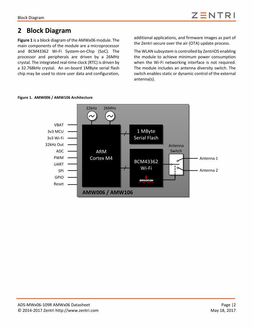
2 Block DiagramFigure 1 is a block diagram of the AMWx06 module. The main components of the module are a microprocessor and BCM43362 Wi-Fi System-on-Chip (SoC). The processor and peripherals are driven by a 26MHz crystal. The integrated real-time clock (RTC) is driven by a 32.768kHz crystal. An on-board 1MByte serial flash chip may be used to store user data and configuration,
additional applications, and firmware images as part of the Zentri secure over the air (OTA) update process.
The WLAN subsystem is controlled by ZentriOS enabling the module to achieve minimum power consumption when the Wi-Fi networking interface is not required. The module includes an antenna diversity switch. The switch enables static or dynamic control of the external antenna(s).
Figure 1. AMW006 / AMW106 Architecture
Antenna Switch
VBAT
3v3 MCU
3v3 Wi-Fi
32kHz Out
ADC
PWM
UART
SPI
GPIO
Reset
ARM Cortex M4
BCM43362 Wi-Fi
26MHz
32kHz
1 MByte Serial Flash
AMW006 / AMW106
Antenna 1
Antenna 2

Electrical Specifications
ADS-MWx06-109R AMWx06 Datasheet Page |3 © 2014-2017 Zentri http://www.zentri.com May 18, 2017
3 Electrical Specifications
3.1 Absolute Maximum Ratings
CAUTION! The absolute maximum ratings in Table 1 and Table 2 indicate levels where permanent damage to the device can occur, even if these limits are exceeded for only a brief duration. Functional operation is not guaranteed under these conditions. Operation at absolute maximum conditions for extended periods can adversely affect long-term reliability of the device.
The values in Table 1 reflect absolute maximum ratings from the respective microprocessor and BCM43362 datasheets.
Table 1. Absolute Maximum Voltage Ratings
Symbol Ratings Min Max Unit
VBAT External power supply voltage to MCU VBAT pin -0.3 4.0
V VDD_3V3 External power supply voltage to MCU subsystem -0.3 4.0
VDD_WIFI External power supply voltage to WLAN subsystem -0.5 6.0
Vin Input voltage on any other MCU pin GND - 0.3 VDD_3V3 + 4.0
Table 2. Absolute Maximum Environmental Ratings
Characteristic Note Min Max Unit
Storage Temperature – -40 +125 °C
Relative Humidity Non-condensing (storage) – 65 %
3.2 Recommended Operating Conditions
Functional operation is not guaranteed outside the limits shown in Table 3 and Table 4, and operation outside these limits for extended periods can adversely affect long-term reliability of the device.
3.2.1 DC Operating Conditions
Table 3. Recommended DC Operating Conditions
Symbol Ratings Min Typ Max Unit
VBAT External power supply voltage to MCU VBAT pin 3.0 3.3 3.6
V VDD_3V31 External power supply voltage to MCU subsystem 3.0 3.3 3.6
VDD_WIFI1,2 External power supply voltage to WLAN subsystem 3.0 3.3 3.6
Notes: 1. VDD_3V3 and VDD_WIFI must be at the same voltage when using the Wi-Fi subsystem 2. The performance of the Wi-Fi subsystem is degraded significantly at low voltages

Electrical Specifications
ADS-MWx06-109R AMWx06 Datasheet Page |4 © 2014-2017 Zentri http://www.zentri.com May 18, 2017
3.2.2 Environmental Conditions
Table 4. Recommended Environmental Conditions
Characteristic Note Min Max Unit
Ambient Temperature Limited by WLAN chip specification -30 +85 °C
Relative Humidity Non-condensing (operating) – 85 %
3.3 Power Consumption
Table 5. Power consumption (VDD_3V3, VDD_WIFI, VBAT @ 3.3V)
Operational State Note Typ1 Max1 Max1 Unit
TA = 25°C
TA = 85°C
VBAT7 MCU VBAT Mode, RTC on, Wi-Fi powered off 0.97 – 3.0 µA
Standby7 MCU Standby Mode, RTC on, Wi-Fi powered off 3.8 5.0 17.0 µA
Stop3, 7 MCU Stop Mode, Wi-Fi powered off 10 28 230 µA
Wi-Fi Powersave2,3 MCU Stop mode, Wi-Fi in powersave 0.77 – – mA
Active Receive2,3,4 MCU Stop mode, Wi-Fi active receive 5.7 – – mA
Active Transmit2,3,5 MCU Stop mode, Wi-Fi active transmit 11.4 – – mA
Wi-Fi Tx Test Mode6 MCU Stop mode, Wi-Fi active transmit – 320 – mA
Notes: 1. Total combined current consumed by all power supplies: VBAT, VDD_3V3, VDD_WIFI. 2. 802.11 beacon Interval = 102.4ms, DTIM=3, Beacon Duration = 1ms @ 1Mbps. 3. MCU Stop Mode with 113µs wakeup latency (flash in deep power down mode), VDD_WIFI = 0V 4. Average current receiving 1Mbit/s UDP at 802.11n MCS7 5. Average current transmitting 1Mbit/s UDP at 802.11n MCS7 6. Wi-Fi Transmitting at +18dBm CCK 11Mbit/s with maximum duty cycle 7. Hardware capability; minimum power consumption is dependent on ZentriOS version and external components
connected to AMWx06 pins
3.4 32kHz Crystal
Table 6. 32kHz Crystal Specifications1
Operational State Note Min Typical Max Unit
Frequency – 32768 – Hz
Frequency Tolerance – 20 – ppm
Frequency Ageing Measured @25°C ±3°C -3 – +3 ppm
Notes:

WLAN RF Specifications
ADS-MWx06-109R AMWx06 Datasheet Page |5 © 2014-2017 Zentri http://www.zentri.com May 18, 2017
1. Reproduced from manufacturer’s datasheet.
4 WLAN RF Specifications The AMWx06 WLAN radio specifications are derived from the Broadcom BCM43362 WLAN radio specifications.
Unless otherwise stated, the specifications in this section apply when the operating conditions are within the limits specified in Section 3.2, Recommended Operating Conditions. Functional operation outside these limits is not guaranteed.
All specifications are measured by connecting directly to either of the antenna ports via a short PCB trace with the other antenna port terminated in 50 ohms.
4.1 Summary WLAN Specifications
Table 7. Summary WLAN Specifications
Feature Supported Description
WLAN Standard IEEE 802.11b/g/n 1x1 SISO
Frequency Band 2.400 GHz – 2.484 GHz
WLAN Channels Channels 1 – 13
Data Rates 802.11b (1, 2, 5.5, 11 Mbps)
802.11g (6, 9, 12, 24, 36, 48, 54 Mbps)
802.11n (HT20 MCS0-MCS7)
Maximum Receive level @ 2.4GHz
-2.5 dBm @ 1, 2 Mbps (8% PER, 1024 octets)
-8.5 dBm @ 5.5, 11 Mbps (8% PER, 1024 Octets)
-12 dBm @ 6-54 Mbps (10% PER, 1000 Octets)
Maximum RF Tx Output Power +18 dBm @ 802.11b (EVM < -9 dB)
+14 dBm @ 802.11n MCS7 (EVM < -28 dB)
Carrier Frequency Accuracy ±20 ppm (26MHz crystal with ±10 ppm @ 25C)
4.2 WLAN Receiver Specifications
Table 8. WLAN Receiver Performance Specifications
Parameter Condition/Notes Min Typical Max Unit
Frequency Range – 2400 – 2500 MHz
Operating Temperature1 – -30 – +85 °C
Receive Sensitivity2
(8% PER for 1024 octet PSDU) at either antenna port3
1 Mbps DSSS – -94 -91
dBm 11 Mbps CCK – -87 -83
Receive Sensitivity2
(10% PER for 1000 octet PSDU) at either antenna port3
6 Mbps OFDM – -86 -81
dBm 54 Mbps OFDM – -73 -69

WLAN RF Specifications
ADS-MWx06-109R AMWx06 Datasheet Page |6 © 2014-2017 Zentri http://www.zentri.com May 18, 2017
Parameter Condition/Notes Min Typical Max Unit
Receive Sensitivity2
(10% PER for 4096 octet PSDU) at either antenna port3. Defined for default parameters: GF, 800ns GI, and non-STBC
65 Mbps MCS0, HT20 – -86 -81
dBm 65 Mbps MCS7, HT20 – -70 -65
Max. Receive Level @ 2.4GHz @ 1, 2 Mbps (8% PER, 1024 octets) -2 – –
dBm @ 5.5, 11 Mbps (8% PER, 1024 Octets) -8 – –
@ 6-54 Mbps (10% PER, 1000 Octets) -11.5 – –
Notes: 1. Operation below -20°C and above +65°C with parameter derating per Note 2 2. Derate receive sensitivity by 1.5dB for operation between temperatures of -30°C to -20°C and 65°C to 85°C 3. All measurements performed with the other antenna port terminated in 50 ohms
4.3 WLAN Transmitter Specifications
Table 9. WLAN Transmitter Performance Specifications
Parameter Condition/Notes Min Typical Max Unit
Frequency Range – 2400 – 2500 MHz
Operating Temperature1 – -30 – +85 °C
Transmit power2 measured at either antenna port3 for highest power level setting at 25°C, VDD-3V3_RF_IN=3.3V with spectral mask and EVM compliance
EVM does NOT exceed :
1 Mbps DSSS -11 dB +14 +16 +18
dBm
11 Mbps CCK -11 dB +14 +16 +18
6 Mbps OFDM -22 dB +12 +14 +16
54 Mbps OFDM -25 dB +12 +14 +16
MCS0, HT20 -22 dB +10 +12 +14
MCS7, HT20 -28 dB +10 +12 +14
Notes: 1. Operation below -20°C and above +65°C with parameter derating per Note 2 2. Derate transmit power by 1.5dB for operation between temperatures of -30°C to -20°C and 65°C to 85°C 3. All measurements performed with the other antenna port terminated in 50 ohms
Pinout and Signal Descriptions
ADS-MWx06-109R AMWx06 Datasheet Page |7 © 2014-2017 Zentri http://www.zentri.com May 18, 2017
5 Pinout and Signal Descriptions
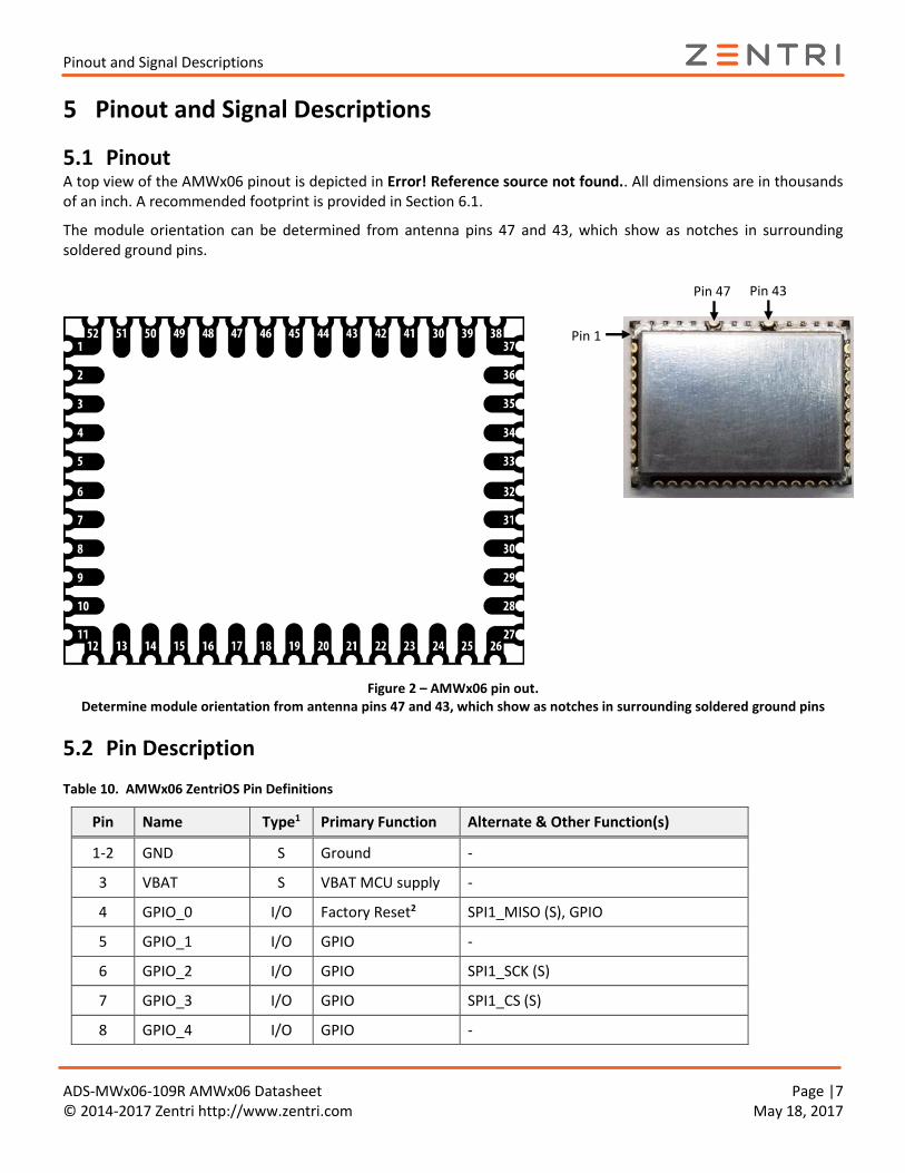
5.1 Pinout A top view of the AMWx06 pinout is depicted in Error! Reference source not found.. All dimensions are in thousands of an inch. A recommended footprint is provided in Section 6.1.
The module orientation can be determined from antenna pins 47 and 43, which show as notches in surrounding soldered ground pins.
Figure 2 – AMWx06 pin out. Determine module orientation from antenna pins 47 and 43, which show as notches in surrounding soldered ground pins
5.2 Pin Description
Table 10. AMWx06 ZentriOS Pin Definitions
Pin Name Type1 Primary Function Alternate & Other Function(s)
1-2 GND S Ground -
3 VBAT S VBAT MCU supply -
4 GPIO_0 I/O Factory Reset2 SPI1_MISO (S), GPIO
5 GPIO_1 I/O GPIO -
6 GPIO_2 I/O GPIO SPI1_SCK (S)
7 GPIO_3 I/O GPIO SPI1_CS (S)
8 GPIO_4 I/O GPIO -
Pin 1
Pin 47 Pin 43

Pinout and Signal Descriptions
ADS-MWx06-109R AMWx06 Datasheet Page |8 © 2014-2017 Zentri http://www.zentri.com May 18, 2017
Pin Name Type1 Primary Function Alternate & Other Function(s)
9 OSC_32K_OUT O OSC_32K_OUT -
10 VDD_3V3 I/O 3.3V MCU supply
11-12 GND S Ground -
13 GPIO_5 I/O GPIO SPI1_MOSI (slave), PWM5
14 GPIO_6 I/O SPI0_MISO (M) 5 ADC6 (when SPI not in use). Not available for digital I/O.
15 GPIO_7 I/O SPI0_SCK (M) 5 ADC5 (when SPI not in use). Not available for digital I/O.
16 GPIO_8 I/O SPI0_MOSI (M) 5 ADC7 (when SPI not in use). Not available for digital I/O.
17 GPIO_9 I/O GPIO UART0_RTS
18 GPIO_10 I/O GPIO UART0_CTS, PWM0
19 GPIO_11 I/O UART0_RX GPIO, PWM0
20 GPIO_12 I/O UART0_TX GPIO, PWM0
21 GPIO_13 I/O GPIO PWM1
22 GPIO_14 I/O GPIO PWM3
23 GPIO_15 I/O GPIO PWM3
24 GPIO_16 I/O GPIO PWM6
25 GPIO_17 I/O GPIO UART1_RX, ADC3, PWM4
26-27 GND I/O Ground -
28 GPIO_18 I/O GPIO -
29 GPIO_19 I/O GPIO UART1_TX, ADC2, PWM4
30 GPIO_20 I/O GPIO ADC9, PWM2
31 GPIO_21 I/O GPIO ADC8, PWM2
32 GPIO_22 I/O GPIO UART1_CTS, WAKE, ADC0, PWM1
33 GPIO_23 I/O GPIO UART1_RTS, ADC1, PWM4
34 RESET_N I System Reset4
35 VDD_WIFI S 3.3V WLAN supply -
36-42 GND S Ground -
43 ANTENNA_1 O Wi-Fi Antenna3 -
44-46 GND S Ground -
47 ANTENNA_2 O Wi-Fi Antenna3 -

Design Guidelines
ADS-MWx06-109R AMWx06 Datasheet Page |9 © 2014-2017 Zentri http://www.zentri.com May 18, 2017
Pin Name Type1 Primary Function Alternate & Other Function(s)
48-52 GND S Ground -
Notes: 1. I = Input, O = Output, S = Supply 2. Factory reset is sampled at power-on-reset and available for other purposes thereafter. 3. Wi-Fi Antenna pins are AC-coupled and have a nominal 50 ohms output impedance. 4. The module Reset pin is connected to the internal MCU via a 1k resistor.
We recommend driving the pin. If the pin is not driven, connect a 0.1uF capacitor to ground close to the pin to bypass noise which may cause unintended reset.
5. Connected to SPI serial flash inside the module.
6 Design Guidelines
6.1 Recommended PCB Footprint
All dimensions in Figure 3 are in thousands of an inch unless otherwise marked. Figure 3. AMWx06 Recommended Footprint (Top)

Design Guidelines
ADS-MWx06-109R AMWx06 Datasheet Page |10 © 2014-2017 Zentri http://www.zentri.com May 18, 2017
6.2 Routing Recommendations
When designing a carrier board, the addition of ground fill directly underneath the AMWx06 module, rather than signal or power traces, is recommended. If traces must be routed directly beneath the module, avoid routing directly underneath keepout areas shown in Figure 4 (ground fill is ok). All ground pads adjacent to antenna pins must be connected to a solid ground plane. Failure to comply with these recommendations may result in degraded performance of WLAN functionality.
Figure 4. AMWx06 Keepouts (TOP VIEW)
Design Guidelines
ADS-MWx06-109R AMWx06 Datasheet Page |11 © 2014-2017 Zentri http://www.zentri.com May 18, 2017
6.3 Soldering Information
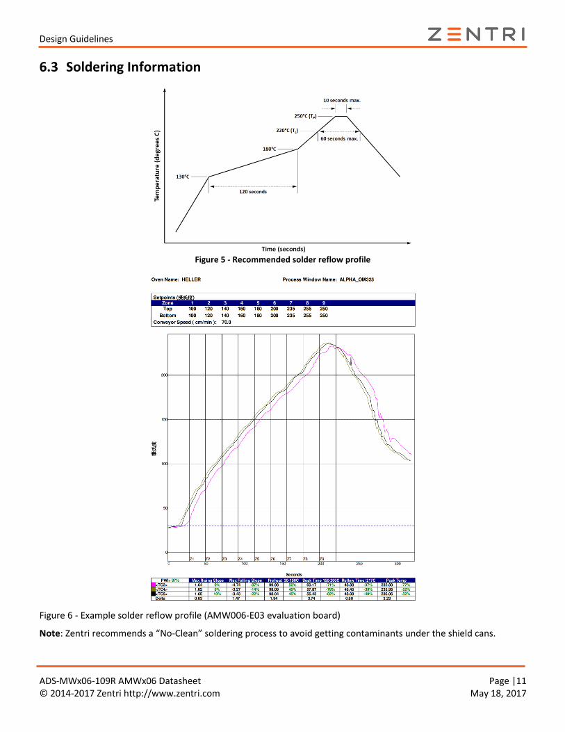
Figure 5 - Recommended solder reflow profile
Figure 6 - Example solder reflow profile (AMW006-E03 evaluation board)
Note: Zentri recommends a “No-Clean” soldering process to avoid getting contaminants under the shield cans.
Design Guidelines
ADS-MWx06-109R AMWx06 Datasheet Page |12 © 2014-2017 Zentri http://www.zentri.com May 18, 2017
6.4 Module Photograph Figure 7. AMW006 Photograph (Top)
6.5 External Antennas
The AMWx06 module supports two external antennas and per-packet antenna diversity to achieve maximum range. Antenna selection is available by setting ZentriOS variables.
NOTE! BOTH antenna ports must be terminated in 50 ohms. If a single antenna is used, the other antenna port should be terminated with a 50 ohm load. Failure to terminate both antenna ports may result in degraded radio performance.
Table 11 - Tested External Antenna Types
Model Type1 Gain (dBi)
Printed antenna PCB trace 3.2
Wire Monopole 2.1
Johanson Tech.
2450AT42A100E
Chip 0.0
ACA-1SRPP-2400 Monopole 0.6
ACA-4HSRPP-
2458
Monopole 1.0
(1) An antenna type comprises antennas having similar in-band and out-of-band radiation patterns.
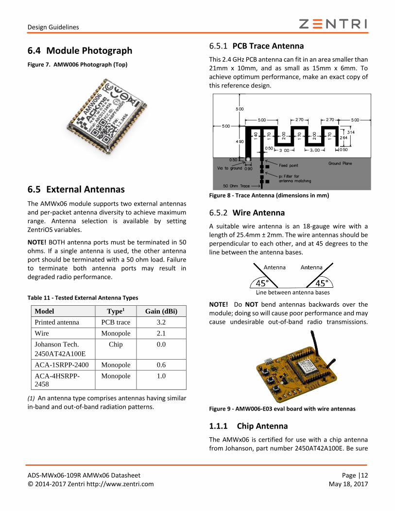
6.5.1 PCB Trace Antenna
This 2.4 GHz PCB antenna can fit in an area smaller than 21mm x 10mm, and as small as 15mm x 6mm. To achieve optimum performance, make an exact copy of this reference design.
Figure 8 - Trace Antenna (dimensions in mm)
6.5.2 Wire Antenna
A suitable wire antenna is an 18-gauge wire with a length of 25.4mm ± 2mm. The wire antennas should be perpendicular to each other, and at 45 degrees to the line between the antenna bases.
NOTE! Do NOT bend antennas backwards over the module; doing so will cause poor performance and may cause undesirable out-of-band radio transmissions.
Figure 9 - AMW006-E03 eval board with wire antennas
1.1.1 Chip Antenna
The AMWx06 is certified for use with a chip antenna from Johanson, part number 2450AT42A100E. Be sure
Design Guidelines
ADS-MWx06-109R AMWx06 Datasheet Page |13 © 2014-2017 Zentri http://www.zentri.com May 18, 2017
to follow the antenna layout design guidelines in the antenna datasheet.
Figure 10 – Chip antenna layout example
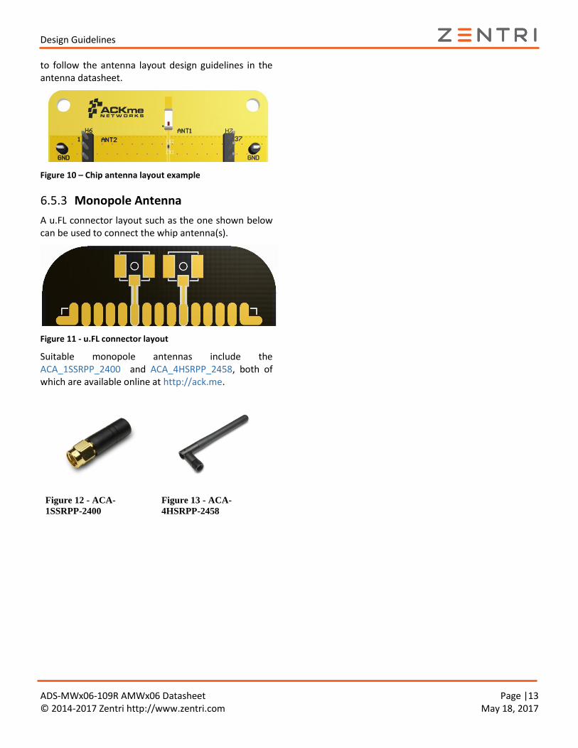
6.5.3 Monopole Antenna
A u.FL connector layout such as the one shown below can be used to connect the whip antenna(s).
Figure 11 - u.FL connector layout
Suitable monopole antennas include the ACA_1SSRPP_2400 and ACA_4HSRPP_2458, both of which are available online at http://ack.me.
Figure 12 - ACA-
1SSRPP-2400
Figure 13 - ACA-
4HSRPP-2458

Design Guidelines
ADS-MWx06-109R AMWx06 Datasheet Page |14 © 2014-2017 Zentri http://www.zentri.com May 18, 2017
6.6 Application Examples
6.6.1 Operation using ZentriOS
To use ZentriOS, the module only requires an external connection to power and a UART serial interface. A host processor connects to UART0 (pins 19/20) or UART1 (pins 25/29) as shown in Figure 14.
Figure 14. Using the AMW006 Module with ZentriOS and a UART serial interface

Regulatory Certification
ADS-MWx06-109R AMWx06 Datasheet Page |15 © 2014-2017 Zentri http://www.zentri.com May 18, 2017
7 Regulatory Certification The AMW006 module has been certified for operation in various regulatory domains. This section outlines certification information specific to the following countries and regions:
United States
Canada
Europe
Australia
New Zealand
Japan
Should you require regulatory certification for the AMW006 module in a country or region not listed, please contact your local Zentri sales office or create a support request via our website at http://ack.me/contact.
7.1 United States
The Zentri AMW006 module has received Federal Communications Commission (FCC) CFR47 Telecommunications, Part 15 Sub-part C “Intentional Radiators” modular approval in accordance with Part 15.212 Modular Transmitter approval. Modular approval allows the end user to integrate the AMW006 module into a finished product without obtaining subsequent and separate FCC approvals for intentional radiation, provided no changes or modifications are made to the module circuitry. Changes or modifications could void the user’s authority to operate the equipment. The end user must comply with all of the instructions provided by the Grantee which indicate installation and/or operating conditions necessary for compliance.
The finished product is required to comply with all applicable FCC equipment authorization, regulations, requirements, and equipment functions not associated with the transmitter module portion. For example, compliance must be demonstrated to regulations for other transmitter components within the host product; to requirements for unintentional radiators (Part 15 Sub-part B “Unintentional Radiators”), such as digital devices, computer peripherals, radio receivers, etc.; and to additional authorization requirements for non-transmitter functions on the transmitter module (i.e. Verification, or Declaration of Conformity) (e.g.,
transmitter modules may also contain digital logic functions) as appropriate.
7.1.1 Labeling and User Information Requirements
The AMW006 module has been labelled with a unique FCC ID number, and if the FCC ID is not visible when the module is installed inside another device, then the outside of the finished product into which the module is installed must also display a label referring to the enclosed module. This exterior label can use wording as follows:
The user manual for the product should include the following statement:
Contains FCC ID: 2ABPY-B5BD9 This device complies with Part 15 of the FCC Rules. Operation is subject to the following two conditions: (1) this device may not cause harmful interference, and (2) this device must accept any interference received, including interference that may cause undesired operation.

Regulatory Certification
ADS-MWx06-109R AMWx06 Datasheet Page |16 © 2014-2017 Zentri http://www.zentri.com May 18, 2017
Additional information on labeling and user information requirements for Part 15 devices can be found in KDB Publication 784748 available at the FCC Office of Engineering and Technology (OET) Laboratory Division Knowledge Database (KDB) at the following website: https://apps.fcc.gov/oetcf/kdb/index.cfm
7.1.2 RF Exposure
All transmitters regulated by FCC must comply with RF exposure requirements. OET Bulletin 65, Evaluating Compliance with FCC Guidelines for Human Exposure to Radio Frequency Electromagnetic Fields, provides assistance in determining whether proposed or existing transmitting facilities, operations or devices comply with limits for human exposure to Radio Frequency (RF) fields adopted by the Federal Communications Commission (FCC). The bulletin offers guidelines and suggestions for evaluating compliance.
If appropriate, compliance with exposure guidelines for mobile and unlicensed devices can be accomplished by
the use of warning labels and by providing users with information concerning minimum separation distances from transmitting structures and proper installation of antennas.
The following statement must be included as a CAUTION statement in manuals and OEM products to alert users of FCC RF exposure compliance:
If the AMW006 module is used in a portable application (i.e., the antenna is less than 20 cm from persons during operation), the integrator is responsible for performing Specific Absorption Rate (SAR) testing in accordance with FCC rules 2.1091.
7.1.3 Approved External Antenna Types
Modular approval testing of the AMW006 was performed with the antenna types listed in Table 11 - Tested External Antenna Types.
To maintain modular approval in the United States, only the tested antenna types shall be used. It is permissible to use different antenna manufacturers provided the antenna types match: in-band and out-of-band radiation patterns and antenna gain must be similar to those tested.
7.1.4 Further Information
Additional information regarding FCC certification and use of the AMW006 module in the United States is available from the following sources.
Federal Communications Commission (FCC) http://www.fcc.gov.au
FCC Office of Engineering and Technology (OET) Laboratory Division Knowledge Database (KDB) http://apps.fcc.gov/oetcf/kdb/index.cfm
This equipment has been tested and found to com-ply with the limits for a Class B digital device, pursuant to part 15 of the FCC Rules. These limits are designed to provide reasonable protection against harmful interference in a residential installation. This equipment generates, uses and can radiate radio frequency energy and if not installed and used in accordance with the instructions, may cause harmful interference to radio communications. However, there is no guarantee that interference will not occur in a particular installation. If this equipment does cause harmful interference to radio or television reception, which can be determined by turning the equipment off and on, the user is encouraged to try to correct the interference by one or more of the following measures:
Reorient or relocate the receiving antenna.
Increase the separation between the equipment and receiver.
Connect the equipment into an outlet on a circuit different from that to which the receiver is connected.
Consult the dealer or an experienced radio/TV technician for help.
To satisfy FCC RF Exposure requirements for mobile and base station transmission devices, a separation distance of 20 cm or more should be maintained between the antenna of this device and persons during operation. To ensure compliance, operation at closer than this distance is not recommended. The antenna(s) used for this transmitter must not be co-located or operating in conjunction with any other antenna or transmitter

Regulatory Certification
ADS-MWx06-109R AMWx06 Datasheet Page |17 © 2014-2017 Zentri http://www.zentri.com May 18, 2017
7.2 Canada
The AMW006 module has been certified for use in Canada under Industry Canada (IC) Radio Standards Specification (RSS) RSS-210 and RSSGen. Modular approval permits the installation of a module in a host device without the need to recertify the device.
7.2.1 Labeling and User Information Requirements
Labeling Requirements for the Host Device (from Section 3.2.1, RSS-Gen, Issue 3, December 2010): The host device shall be properly labeled to identify the module within the host device.
The Industry Canada certification label of a module shall be clearly visible at all times when installed in the host device, otherwise the host device must be labeled to display the Industry Canada certification number of the module, preceded by the words “Contains transmitter module”, or the word “Contains”, or similar wording expressing the same meaning, as follows:
User Manual Notice for License-Exempt Radio Apparatus (from Section 7.1.3 RSS-Gen, Issue 3, December 2010): User manuals for license-exempt radio apparatus shall contain the following or equivalent notice in a conspicuous location in the user manual or alternatively on the device or both:
Transmitter Antenna Notification (from Section 7.1.2 RSS-Gen, Issue 3, December 2010): User manuals for transmitters shall display the following notice in a conspicuous location:
The above notice may be affixed to the device instead of displayed in the user manual.
Contains transmitter module IC: 11685A-61F8D
This device complies with Industry Canada license-exempt RSS standard(s). Operation is subject to the following two conditions: (1) this device may not cause interference, and (2) this device must accept any interference, including interference that may cause undesired operation of the device.
Le présent appareil est conforme aux CNR d'Industrie Canada applicables aux appareils radio exempts de licence. L'exploitation est autorisée aux deux onditions suivantes: (1) l'appareil ne doit pas produire de brouillage, et (2) l'utilisateur de l'appareil doit accepter tout brouillage radioélectrique subi, meme si le brouillage est susceptible d'en compromettre le fonctionnement.
Under Industry Canada regulations, this radio transmitter may only operate using an antenna of a type and maximum (or lesser) gain approved for the transmitter by Industry Canada. To reduce potential radio interference to other users, the antenna type and its gain should be so chosen that the equivalent isotropically radiated power (EIRP) is not more than that necessary for successful communication.
Conformément à la réglementation d'Industrie Can-ada, le présent émetteur radio peut fonctionner avec une antenne d'un type et d'un gain maximal (ou inférieur) approuvé pour l'émetteur par Industrie Canada. Dans le but de réduire les risques de brouil-lage radioélectrique à l'intention des autres utilisa-teurs, il faut choisir le type d'antenne et son gain de sorte que la puissance isotrope rayonnée équivalente (p.i.r.e.) ne dépasse pas l'intensité nécessaire à l'établissement d'une communication satisfaisante.

Regulatory Certification
ADS-MWx06-109R AMWx06 Datasheet Page |18 © 2014-2017 Zentri http://www.zentri.com May 18, 2017
User manuals for transmitters equipped with detach-able antennas shall also contain the following notice in a conspicuous location:
Immediately following the above notice, the manufacturer shall provide a list of all antenna types approved for use with the transmitter, indicating the maximum permissible antenna gain (in dBi) and required impedance for each.
7.2.2 External Antenna Types
Modular approval testing of the AMW006 was performed with the antenna types listed in Table 11 - Tested External Antenna Types.
Transmitter Antenna (from Section 7.1.2 RSS-Gen, Issue 3, December 2010):
The AMW006 module can only be sold or operated with antennas with which it was approved. Transmitter may be approved with multiple antenna types. An antenna type comprises antennas having similar in-band and out-of-band radiation patterns. Testing shall be performed using the highest gain antenna of each combination of transmitter and antenna type for which approval is being sought, with the transmitter output
power set at the maximum level. Any antenna of the same type having equal or lesser gain as an antenna that had been successfully tested with the transmitter, will also be considered approved with the transmitter, and may be used and marketed with the transmitter.
When a measurement at the antenna connector is used to determine RF output power, the effective gain of the device's antenna shall be stated, based on measurement or on data from the antenna manufacturer.
For transmitters of output power greater than 10 milliwatts, the total antenna gain shall be added to the measured RF output power to demonstrate compliance to the specified radiated power limits.
7.2.3 Further Information
Additional information may be obtained from the Industry Canada website at http://www.ic.gc.ca
7.3 Europe
The AMW006 module is an R&TTE Directive assessed radio module that is CE marked and has been manufactured and tested with the intention of being integrated into a final product.
The AMW006 module has been tested to R&TTE Directives as summarized in Table 12. European Compliance Testing. Opinion has also been issued. All AMW006 test reports are available on the Zentri website at https://www.zentri.com/contact-us.
The R&TTE Compliance Association provides guidance on modular devices in the document titled Technical Guidance Note 01 available on the website at http://www.rtteca.com/html/download_area.htm.
This radio transmitter (identify the device by certification number, or model number if Category II) has been approved by Industry Canada to operate with the antenna types listed below with the maximum permissible gain and required antenna impedance for each antenna type indicated. Antenna types not included in this list, having a gain greater than the maximum gain indicated for that type, are strictly prohibited for use with this device.
Le présent émetteur radio (identifier le dispositif par son numéro de certification ou son numéro de modèle s'il fait partie du matériel de catégorie I) a été approuvé par Industrie Canada pour fonctionner avec les types d'antenne énumérés ci-dessous et ayant un gain admissible maximal et l'impédance requise pour chaque type d'antenne. Les types d'antenne non inclus dans cette liste, ou dont le gain est supérieur au gain maximal indiqué, sont strictement interdits pour l'exploitation de l'émetteur.

Regulatory Certification
ADS-MWx06-109R AMWx06 Datasheet Page |19 © 2014-2017 Zentri http://www.zentri.com May 18, 2017
7.3.1 Labeling and User Information Requirements
The label on the final product which contains the AMW006 module must follow CE marking requirements. The R&TTE Compliance Association Technical Guidance Note 01 provides guidance on final product CE marking
7.3.1 External Antenna Requirements
From R&TTE Compliance Association document Technical Guidance Note 01:
Provided the integrator installing an assessed radio module with an integral or specific antenna and installed in conformance with the radio module manufacturer’s installation instructions requires no further evaluation under Article 3.2 of the R&TTE Directive and does not require further involvement of an R&TTE Directive Notified Body for the final product. [Section 2.2.4]
The European Compliance Testing listed in Table 12. European Compliance Testing was performed using antenna types listed in Table 11 - Tested External Antenna Types.
7.3.2 Further Information A document that can be used as a starting point in understanding the use of Short Range Devices (SRD) in Europe is the European Radio Communications Committee (ERC) Recommendation 70-03 E, which can be downloaded from the European Radio Communications Office (ERO) at: http://www.ero.dk.
Further information may be obtained from the following websites:
Radio and Telecommunications Terminal Equipment (R&TTE) http://ec.europa.eu/enterprise/rtte/index_en.htm
European Conference of Postal and Telecommunications Administrations (CEPT) http://www.cept.org
European Telecommunications Standards Institute (ETSI) http://www.etsi.org
European Radio Communications Office (ERO) http://www.ero.dk
The Radio and Telecommunications Terminal Equipment Compliance Association (R&TTE CA) http://www.rtteca.com/
NOTE: To maintain conformance to the testing listed in Table 12. European Compliance Testing, the module shall be installed in accordance with the installation instructions in this data sheet and shall not be modified.
When integrating a radio module into a completed product the integrator becomes the manufacturer of the final product and is therefore responsible for demonstrating compliance of the final product with the essential requirements of the R&TTE Directive.

Regulatory Certification
ADS-MWx06-109R AMWx06 Datasheet Page |20 © 2014-2017 Zentri http://www.zentri.com May 18, 2017
Table 12. European Compliance Testing
Certification Standard Report Number Date Laboratory
Safety EN 60950-1:2006, A11:2009,
A1:2010, A12:2011, A2:2013
W6M21410-
14584-L
Jan 15, 2015 Worldwide Testing
Services (Taiwan) Co.,
Ltd.
EMF EN 62311:2008 EA560122 Jul 1, 2015 Sporton International, Inc.
(Taiwan) EMC EN 301 489-1 v1.9.2 (2011-09), Class
B
EN 301 489-17 v2.2.1 (2012-09)
EN 55022:2010/AC:2011, Class B
EN 55024:2010
EH560122 Jul 1, 2015
Radio EN 300 328 v1.9.1 (2015-02) ER560122 Jul 1, 2015
Notified Body
Opinion 1177
TCF-1334TC15
Jul 5, 2015 TIMCO Engineering, Inc.
7.4 Australia
Australian radio regulations do not provide a modular approval policy similar to the United States (FCC) and Canada (IC). However, AMW006 module test reports may be used in part to demonstrate compliance in accordance with ACMA Radio communications “Short Range Devices” Standard 2004 which references Australia/New Zealand industry standard AS/NZS-4268:2012. AMW006 RF transmitter test reports may be used as part of the product certification and compliance folder. For further information regarding the availability of RF test reports, please contact Zentri at https://www.zentri.com/contact-us.
7.4.1 External Antenna Requirements
Compliance tests were performed using antenna types listed in Table 11 - Tested External Antenna Types.
If an external antenna is used with the AMW006 module, additional testing of the end product is needed to meet Australian regulatory requirements.
7.4.2 Further Information
Additional information may be obtained from the Australian Communications and Media Authority website at http://www.acma.gov.au.
7.5 New Zealand
New Zealand radio regulations do not provide a modular approval policy similar to the United States (FCC) and Canada (IC). However, AMW006 module test reports may be used in part to demonstrate compliance with the New Zealand “General User Radio License for Short Range Devices”. New Zealand Radio communications (Radio Standards) Notice 2010 references Australia/New Zealand industry standard AS/NZS-4268:2012. AMW006 RF transmitter test reports may be used as part of the product certification and compliance folder. For further information regarding the availability of RF test reports, please contact Zentri at https://www.zentri.com/contact-us.
7.5.1 External Antenna Requirements
Compliance tests were performed using antenna types listed in Table 11 - Tested External Antenna Types.
If an external antenna is used with the AMW006 module, additional testing of the end product is needed to meet New Zealand regulatory requirements.

Regulatory Certification
ADS-MWx06-109R AMWx06 Datasheet Page |21 © 2014-2017 Zentri http://www.zentri.com May 18, 2017
7.5.2 Further Information
Additional information may be obtained from the New Zealand Radio Spectrum Ministry of Economic Development website at http://www.rsm.govt.nz.
7.6 Japan The AMW006 has been tested to comply with the radio regulations set forth by the Japanese Ministry of
Internal Affairs and Communications (MIC) as documented in
Table 13. The module is certified for operation with each of the antenna types listed in Table 11 - Tested External Antenna Types.
Table 13. Japan Compliance Testing
Certification Standard Report Number Date Laboratory
Verification of
Compliance
VCCI V-3/2014.04 Class B ITE JV560122 Jul 1, 2015 Sporton International, Inc.
(Taiwan)
Radio Notice No. 88 Appendix No. 43 JRF560122 Jul 1, 2015
Equipment
Marking
152150256/AA/00 Jul 6, 2015 Telefication, BV.
(The Netherlands)

Packaging, Handling and Storage, RoHS
ADS-MWx06-109R AMWx06 Datasheet Page |22 © 2014-2017 Zentri http://www.zentri.com May 18, 2017
8 Packaging, Handling and Storage, RoHS
8.1 Packaging
AMWx06 modules should be hand-soldered ONLY!
If reflow is required, AMWx06 modules must be baked first according to Joint Industry Standard J-STD-033C.
Modules are shipped in cut tape in lengths of 100 modules, with ESD-safe packaging, or in reels of 900 units.
Reels are shipped inside a moisture resistant sealed bag. The shelf life of the sealed reel is 12 months at 40°C and <90% Relative Humidity (RH). Please refer to the bag seal date and the following section for handling and storage.
8.2 Handling & Storage
CAUTION MSL3 Sensitive Device!
The AMW006 module is a moisture sensitive device rated at Moisture Sensitive Level 3 (MSL3) per IPC/JEDEC J-STD-20.
After opening the moisture sealed storage bag, modules that will be subjected to reflow solder or other high temperature processes must be:
1. mounted to a circuit board within 168 hours at factory conditions (≤30°C and <60% RH)
OR
2. continuously stored per IPC/JEDEC J-STD-033
Modules that have been exposed to moisture and environmental conditions exceeding packaging and storage conditions MUST be baked before mounting according to IPC/JEDEC J-STD-033.
Failure to meet packaging and storage conditions will result in irreparable damage to modules during solder reflow.
8.3 RoHS Directive
The AMWx06 module is produced according to the RoHS (Restriction of the use of certain Hazardous Substances in electrical and electronic equipment) directive and complies with the directive.

Packaging, Handling and Storage, RoHS
ADS-MWx06-109R AMWx06 Datasheet Page |23 © 2014-2017 Zentri http://www.zentri.com May 18, 2017
8.4 Tape and Reel Specifications
Figure 15 - Tape Specifications
Symbol A0 B0 D0 E F K0
Specification (mm) 15.6 ± 0.10 20.8 ± 0.10 1.5 ± 0.10 1.75 ± 0.10 20.2 ± 0.10 3.10 ± 0.10
Symbol P P0 P2 T W
Specification (mm) 20.0 ± 0.10 4.00 ± 0.10 2.00 ± 0.10 0.30 ± 0.05 44.0 ± 0.30
Tape material : black PS material, in line with ROHS environmental management substances
Tape thickness: 0.3 mm ± 0.05 mm
Tape width: 44mm (1.76")
Protection zone: black PS material
Distance between chain hole centers within the range of ± 0.2 mm of cumulative error
Anti-camber at 1 mm / 250 mm
All dimensions in line with the requirements of EIA-481-D

Packaging, Handling and Storage, RoHS
ADS-MWx06-109R AMWx06 Datasheet Page |24 © 2014-2017 Zentri http://www.zentri.com May 18, 2017
Figure 16 - Reel Specifications
Symbol A B C1 D E H T
Specification (mm) 2.5 ± 0.2 11 ± 0.2 330 ± 1 99.5 ± 0.1 13.2 ± 0.2 44.8 + 0.3 / -0.2 2.25 ± 0.2
8.5 Cut Tape and Reel Quantity
Cut tape is available in lengths of 100 units.
Smaller quantities may be available from some distributors. If smaller quantities are purchased, ensure that modules are managed in accordance with Moisture Sensitive Level 3 (MSL3) per IPC/JEDEC J-STD-20.
Each reel contains 900 units.

Ordering Information
ADS-MWx06-109R AMWx06 Datasheet Page |25 © 2014-2017 Zentri http://www.zentri.com May 18, 2017
9 Ordering Information You can order AMWx06 as either cut tape loaded with an unspecified ZentriOS, or as a full reel loaded with either a specific ZentriOS version or a version of your embedded custom application.
When you order, refer to the OPN (Orderable Part Number), as described below. For examples, see Table 14. Ordering Information.
9.1 Ordering an Unspecified ZentriOS Version
Order OPN: AMWx06
You can order an unspecified ZentriOS version as cut tape. The OPN is of the form <platform>, where <platform> is AMW006 or AMW106.
When ZentriOS version is unspecified, orders of AMW006 or AMW106 modules ship with whatever versions of ZentriOS are available. The firmware is not guaranteed to be the same for all items shipped. Cut tape is suitable for sampling, evaluation, and pilot builds.
Upon delivery, you can update modules individually, via OTA (Over-The-Air update), with a specific firmware version.
9.2 Ordering a Specific ZentriOS Version or a Custom Firmware Version
ZentriOS version order OPN: AMWx06-x.y.zR
Custom firmware version OPN: AMWx06-xxxxxxR
Volume orders are delivered in reels, as indicated by the R suffix. To ensure consistency, an OPN is specified, corresponding to a specific version.
ZentriOS version: the OPN is of the form <platform>-x.y.zR, where <platform> is AMW006 or AMW106, and x is major version, y is minor version and z is patch version.
Custom firmware version: the OPN is of the form <platform>-xxxxxx, where <platform> is AMW006 or AMW106, and xxxxxx is a unique ID indicating a specific product version. Zentri ships reels with the product version specified.
Custom firmware can be a product bundle for the AMW006 or AMW106. A custom product bundle includes a specific version of ZentriOS. An AMW106 ZAP product bundle also contains a ZAP (ZentriOS application).
Table 14. Ordering Information
Order Type Delivery Format Example OPN
Unspecified firmware Cut tape AMW006 AMW106
Specified ZentriOS version
Full reel box AMW006-3.3.0R AMW106-3.2.2R
Custom firmware Full reel box AMW006-H35GHJR AMW106-FG7L21R

Revision History & Glossary
ADS-MWx06-109R AMWx06 Datasheet Page |26 © 2014-2017 Zentri http://www.zentri.com May 18, 2017
10 Revision History & Glossary
10.1 Revision History
Table 15: Document Revision History
Revision Date Change Description
ADS-MW006-100R Oct 20, 2014 Initial preliminary release
ADS-MW006-101R Nov 25, 2014 Updated schematic, PCB trace antenna
ADS-MW006-102R Mar 20, 2015 Added note on reset pin
ADS-MW006-103R Apr 10, 2015 Added note on MLS3 non-compliance, and note on power consumption
ADS-MW006-104R May 5, 2015 Added solder reflow charts, AMW106 properties
ADS-MW006-105R Jun 9, 2015 Removed AMW106 properties; updated GPIO and ADC details
ADS-MWx06-106R Sep 1, 2015 Added AMW106 Updated/added ETSI/CE v1.9.1 and Japan certification Added tape and reel specifications.
ADS-MWx06-107R June 6, 2016 Converted to Zentri branding.
ADS-MWx06-108R Dec 21, 2016 Corrected tape specifications. Added firmware note in Ordering Information. Adding “No Clean” process note in Soldering Information.
ADS-MWx06-109R May 1, 2017 Added label orientation diagram. Added firmware features page. Revised Ordering Information
10.2 Glossary
In most cases, acronyms and abbreviations are defined on first use. A comprehensive list of acronyms and other terms used in Zentri documents are provided at https://docs.zentri.com/zentri/glossary.

References
ADS-MWx06-109R AMWx06 Datasheet Page |27 © 2014-2017 Zentri http://www.zentri.com May 18, 2017
11 References Throughout this data sheet, references to other documents are listed. The following documents provide additional material:
1. IEEE 802.11 Standard – 2012 Institute of Electrical and Electronics Engineers. http://standards.ieee.org

http://www.silabs.com
Silicon Laboratories Inc.400 West Cesar ChavezAustin, TX 78701USA
Smart. Connected. Energy-Friendly.
Productswww.silabs.com/products
Qualitywww.silabs.com/quality
Support and Communitycommunity.silabs.com
DisclaimerSilicon Labs intends to provide customers with the latest, accurate, and in-depth documentation of all peripherals and modules available for system and software implementers using or intending to use the Silicon Labs products. Characterization data, available modules and peripherals, memory sizes and memory addresses refer to each specific device, and "Typical" parameters provided can and do vary in different applications. Application examples described herein are for illustrative purposes only. Silicon Labs reserves the right to make changes without further notice and limitation to product information, specifications, and descriptions herein, and does not give warranties as to the accuracy or completeness of the included information. Silicon Labs shall have no liability for the consequences of use of the information supplied herein. This document does not imply or express copyright licenses granted hereunder to design or fabricate any integrated circuits. The products are not designed or authorized to be used within any Life Support System without the specific written consent of Silicon Labs. A "Life Support System" is any product or system intended to support or sustain life and/or health, which, if it fails, can be reasonably expected to result in significant personal injury or death. Silicon Labs products are not designed or authorized for military applications. Silicon Labs products shall under no circumstances be used in weapons of mass destruction including (but not limited to) nuclear, biological or chemical weapons, or missiles capable of delivering such weapons.
Trademark InformationSilicon Laboratories Inc.® , Silicon Laboratories®, Silicon Labs®, SiLabs® and the Silicon Labs logo®, Bluegiga®, Bluegiga Logo®, Clockbuilder®, CMEMS®, DSPLL®, EFM®, EFM32®, EFR, Ember®, Energy Micro, Energy Micro logo and combinations thereof, "the world’s most energy friendly microcontrollers", Ember®, EZLink®, EZRadio®, EZRadioPRO®, Gecko®, ISOmodem®, Precision32®, ProSLIC®, Simplicity Studio®, SiPHY®, Telegesis, the Telegesis Logo®, USBXpress® and others are trademarks or registered trademarks of Silicon Labs. ARM, CORTEX, Cortex-M3 and THUMB are trademarks or registered trademarks of ARM Holdings. Keil is a registered trademark of ARM Limited. All other products or brand names mentioned herein are trademarks of their respective holders.