zhc518a-50w~300w tv transmitter user's...
TRANSCRIPT
www.fmuser.org
www.fmuser.org
1
FU-300W
TV Transmitter
User’s Manual
www.fmuser.org
www.fmuser.org
2
Please notice this:
1. Read safety notice first.
2. A 50 Ohm dummy load or antenna and cable must be connected
before turning power on, avoiding water going into the connecters or
the cable.
3. Please read System Control Logic section to fully understand how
the system works.
4. Please read the Power On Sequence.

www.fmuser.org
www.fmuser.org
3
Contents
Safety Notice
1. Overview --------------------------------------------------------------------------------5
2. Technical Specifications --------------------------------------------------------------5
3. System Structure and Function------------------------------------------------------6
4. Test Instrument-------------------------------------------------------------------------7
5. Test and Maintenance -----------------------------------------------------------------8
6. Panel Function Description ---------------------------------------------------------8
7. Power on Sequence -------------------------------------------------------------------9
8. System Control Logic-----------------------------------------------------------------10
9. Direction for Operate and Display ------------------------------------------------10
10. Indicator light-------------------------------------------------------------------------2
11. Failures Check ----------------------------------------------------------------------2
www.fmuser.org
www.fmuser.org
4
Safety Notice
1. Please read the following safety points, in order to avoid the accidents and prevent the
connecting machines to be broken.
2. Only the qualified maintenance workers can operate the service.
3. Prevent the fire and the bodily injury.
a. Use the proper wire. If not, it will cause the fire and the bodily injury;
b. Ensure the machine connect the ground. Please confirm whether the machine has connected
the ground, through the wire and the lead, to prevent the electric shock;
c. Use the proper fuse. Please use the stipulated type and rating fuse;
d. Provide good ventilation. This machine adopts the natural convective radiation. Fix it
correctly to keep it radiating well.
4. Please don’t disassemble and repair by yourself when it’s broken down. Please send to the
professional service department to solve the problems.
CAUTION:Please don’t assemble the machine in the moist environment;
Please don’t assemble the machine in the easy exploding environment;
Please don’t repair by yourself.
www.fmuser.org
www.fmuser.org
5
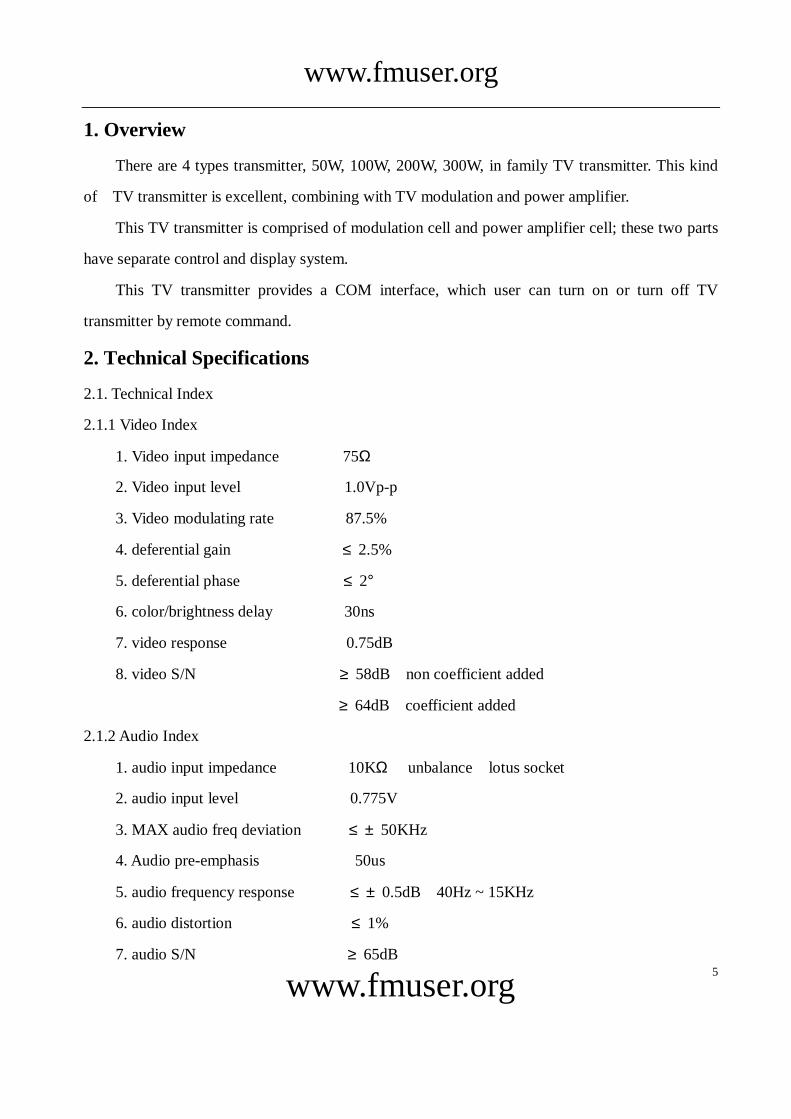
1. Overview
There are 4 types transmitter, 50W, 100W, 200W, 300W, in family TV transmitter. This kind
of TV transmitter is excellent, combining with TV modulation and power amplifier.
This TV transmitter is comprised of modulation cell and power amplifier cell; these two parts
have separate control and display system.
This TV transmitter provides a COM interface, which user can turn on or turn off TV
transmitter by remote command.
2. Technical Specifications
2.1. Technical Index
2.1.1 Video Index
1. Video input impedance 75Ω
2. Video input level 1.0Vp-p
3. Video modulating rate 87.5%
4. deferential gain ≤2.5%
5. deferential phase ≤2°
6. color/brightness delay 30ns
7. video response 0.75dB
8. video S/N ≥58dB(non coefficient added)
≥64dB(coefficient added)
2.1.2 Audio Index
1. audio input impedance 10KΩ(unbalance,lotus socket)
2. audio input level 0.775V
3. MAX audio freq deviation ≤±50KHz
4. Audio pre-emphasis 50us
5. audio frequency response ≤±0.5dB(40Hz ~ 15KHz)
6. audio distortion ≤1%
7. audio S/N ≥65dB
www.fmuser.org
www.fmuser.org
6
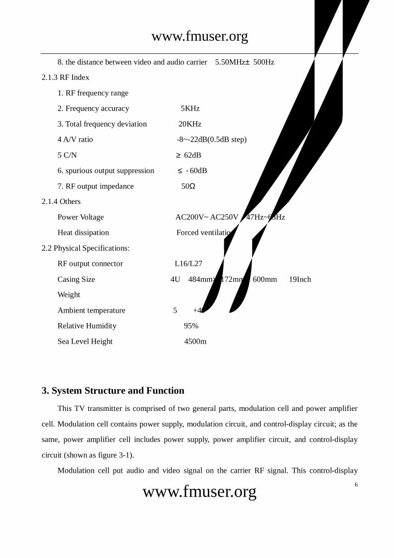
8. the distance between video and audio carrier 5.50MHz±500Hz
2.1.3 RF Index
1. RF frequency range
2. Frequency accuracy 5KHz
3. Total frequency deviation 20KHz
4 A/V ratio -8~-22dB(0.5dB step)
5 C/N ≥62dB
6. spurious output suppression ≤-60dB
7. RF output impedance 50Ω
2.1.4 Others
Power Voltage AC200V~ AC250V 47Hz~63Hz
Heat dissipation Forced ventilation
2.2 Physical Specifications:
RF output connector L16/L27
Casing Size 4U(484mm×172mm×600mm)、19Inch
Weight
Ambient temperature 5℃~+40℃
Relative Humidity <95%
Sea Level Height <4500m
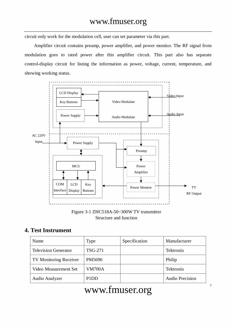
3. System Structure and Function
This TV transmitter is comprised of two general parts, modulation cell and power amplifier
cell. Modulation cell contains power supply, modulation circuit, and control-display circuit; as the
same, power amplifier cell includes power supply, power amplifier circuit, and control-display
circuit (shown as figure 3-1).
Modulation cell put audio and video signal on the carrier RF signal. This control-display
www.fmuser.org
www.fmuser.org
7
circuit only work for the modulation cell, user can set parameter via this part.
Amplifier circuit contains preamp, power amplifier, and power monitor. The RF signal from
modulation goes to rated power after this amplifier circuit. This part also has separate
control-display circuit for listing the information as power, voltage, current, temperature, and
showing working status.
4. Test Instrument
Name Type Specification Manufacturer
Television Generator TSG-271 Tektronix
TV Monitoring Receiver PM5696 Philip
Video Measurement Set VM700A Tektronix
Audio Analyzer P1DD Audio Precision
Video Modulate
Audio Modulate
Preamp
Power
Amplifier
Power Supply
MCU
LCD
Display
COM
Interface
Figure 3-1 ZHC518A-50~300W TV transmitter
Structure and function
Power Monitor TV
RF Output
Key
Buttons
AC 220V
Input
Video Input
Audio Input Power Supply
LCD Display
Key Buttons
www.fmuser.org
www.fmuser.org
8
Wattmeter MODEL 43 0~1KW Bird
50Ω Attenuator DLA-1000W VSWR<1.20
DC-1GHz BED
Table 4-1 Test instrument for ZHC518A-50/100/200/300W TV transmitter
5. Test and Maintenance
As a high performance and high index TV transmitter, ZHC518A-50/100/200/300W TV
transmitter’s relevant specifications such as distortion; audio frequency response, video frequency
response, and signal to noise ratio etc. totally meet the national relevant standards and industry
standards of TV transmitter, and some of their technical specifications is much higher than the
national standards and industry standards.
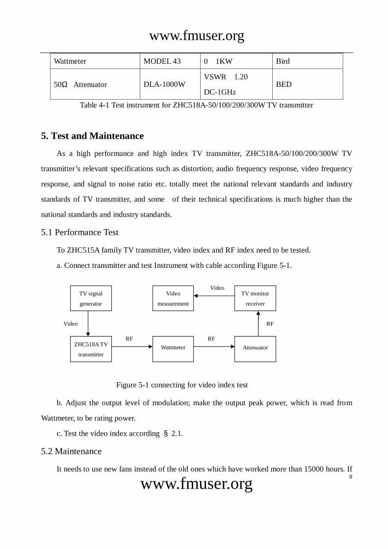
5.1 Performance Test
To ZHC515A family TV transmitter, video index and RF index need to be tested.
a. Connect transmitter and test Instrument with cable according Figure 5-1.
b. Adjust the output level of modulation; make the output peak power, which is read from
Wattmeter, to be rating power.
c. Test the video index according §2.1.
5.2 Maintenance
It needs to use new fans instead of the old ones which have worked more than 15000 hours. If
Figure 5-1 connecting for video index test
ZHC518A TV
transmitter Wattmeter Attenuator
RF RF
RF
Video
Video
TV signal
generator
Video
measurement
TV monitor
receiver
www.fmuser.org
www.fmuser.org
9
the digital FM broadcast transmitter works at a very dirty environment, for example a place with
much of dust, it must be to replace fans ahead of schedule.
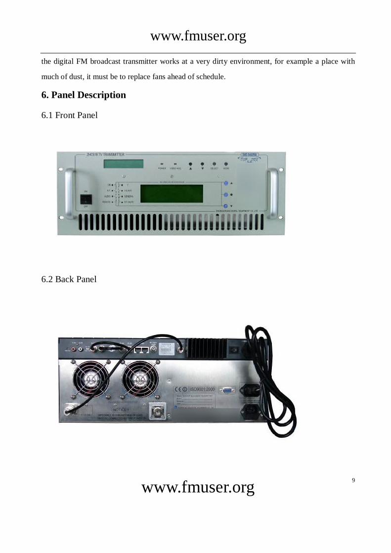
6. Panel Description
6.1 Front Panel
6.2 Back Panel
www.fmuser.org
www.fmuser.org
10
7. Power on Sequence
7.1 Open the package, check appearance, switch, key button, socket, and interface port on front
and back panel.
7.2 Turn power switch on the “OFF” position and connect power cord to power source.
7.3 Connect audio, video, RF cable on the back panel. Connect RF out port to a 50 Ohm dummy
load or antenna through a cable.
7.4 Turn power switch to “ON” at the back panel, then turn power switch to “ON” at the front
panel.
7.5 Turn off RF power.
7.6 Set working parameters.
7.7 Turn on RF power.
8. System Control Logic
8.1 RF Output Control
This TV transmitter’s RF output can be controlled by RF Switch, which is on the “Main Page”
of the LCD.
When RF Switch is OFF, turn off RF power.
When RF Switch is ON, and the video signal input is normal, turn RF power on.
8.2 Remote Control
When remote control is enabled, remote LED on front panel is lit. And power output is
controlled by remote host and can not be changed locally except “Remote” flag is disabled.
RS232 or RS485 are used for remote control. User can ask either of this two. Before enabling
remote control, baud rate and device address should be properly set.
8.3 System Protection
In some urgent cases such as exceeded forward power, reflect power, current and over
temperature, system will reboot. If it is failed successive 3 times, the system will automatically
turns off RF power and just acts display function.
www.fmuser.org
www.fmuser.org
11
9. Direction for Operate and Display
To this TV transmitter, modulation cell and power amplifier cell have separate operate-display
system.
9.1 Operation for Modulation Cell
On the front panel, there is a LCD, “▲”Key, “▼”Key, “Select” Key, “Mode” Key for user to
view and set modulate parameter.
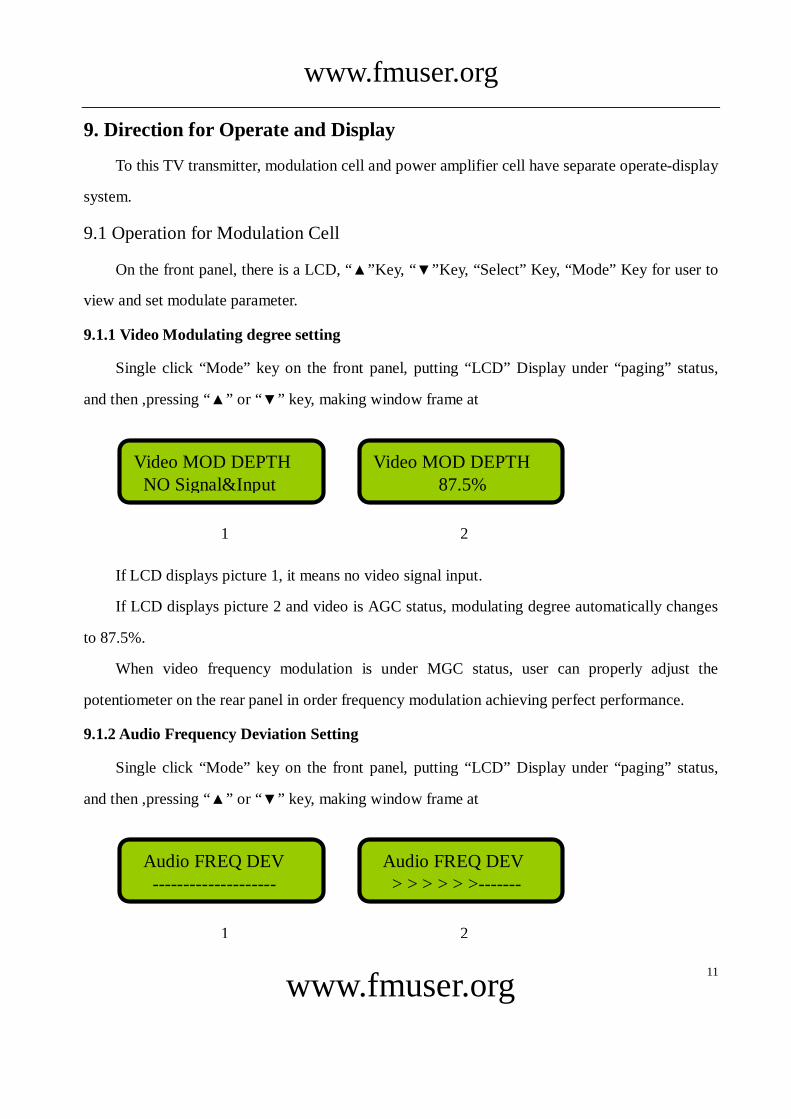
9.1.1 Video Modulating degree setting
Single click “Mode” key on the front panel, putting “LCD” Display under “paging” status,
and then ,pressing “▲” or “▼” key, making window frame at
If LCD displays picture 1, it means no video signal input.
If LCD displays picture 2 and video is AGC status, modulating degree automatically changes
to 87.5%.
When video frequency modulation is under MGC status, user can properly adjust the
potentiometer on the rear panel in order frequency modulation achieving perfect performance.
9.1.2 Audio Frequency Deviation Setting
Single click “Mode” key on the front panel, putting “LCD” Display under “paging” status,
and then ,pressing “▲” or “▼” key, making window frame at
Audio FREQ DEV: --------------------
Audio FREQ DEV: > > > > > >-------
图 1 图 2
Video MOD DEPTH: NO Signal&Input
Video MOD DEPTH: 87.5%
图 1 图 2

www.fmuser.org
www.fmuser.org
12
If LCD displays picture 1, it means no audio signal input, If LCD displays picture 2, user can
press “Select” key, entering variable status, and then, press “▲” or “▼” key, When deviation
appears at the middle, it means modulation frequency deviation ±50KHz. When deviation at the
full mark, it means ±100KHz.
9.1.3 A/V Ratio Setting
Single click “Mode” key on the front panel, putting “LCD” Display under “paging” status,
and then ,pressing “▲” or “▼” key, making window frame at
User can press “Select” key, entering variable status, and then, pressing “▲” or “▼” key
achieving desirable value, finally.(Suggestion: keep the factory default setting)
9.1.4 Program Label Setting
Single click “Mode” key on the front panel, putting “LCD” Display under “paging” status,
and then ,pressing “▲” or “▼” key, making window frame at
The factory default setting is 8 (A)s. If it is necessary to set program label, user can follow the
steps below:
Program: AAAAAAAA
A/V Proportion: - 18.0 dB
www.fmuser.org
www.fmuser.org
13
(1)When setting the first “A”, user can press “Select” key changing it to “*”, and then, pressing
“▲” or “▼” key, changing to desired letter.
(2)When setting the second “A”, user can press “Select” key changing it to “*”, and then,
pressing “▲” or “▼” key, changing to desired letter.
(3)Repeating step A or step B, until getting needed program label, finally pressing “Mode” to
save the change.
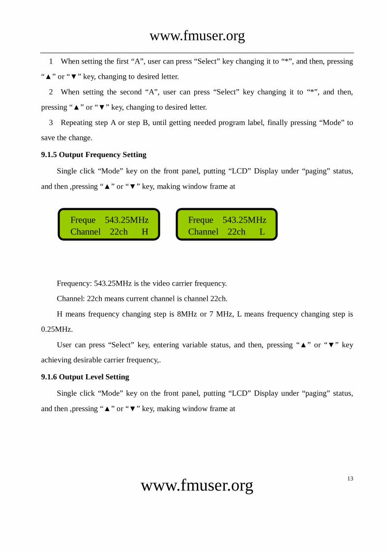
9.1.5 Output Frequency Setting
Single click “Mode” key on the front panel, putting “LCD” Display under “paging” status,
and then ,pressing “▲” or “▼” key, making window frame at
Frequency: 543.25MHz is the video carrier frequency.
Channel: 22ch means current channel is channel 22ch.
H means frequency changing step is 8MHz or 7 MHz, L means frequency changing step is
0.25MHz.
User can press “Select” key, entering variable status, and then, pressing “▲” or “▼” key
achieving desirable carrier frequency,.
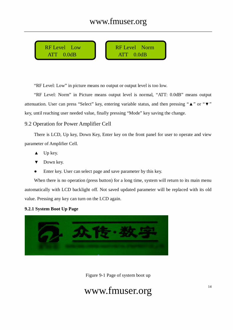
9.1.6 Output Level Setting
Single click “Mode” key on the front panel, putting “LCD” Display under “paging” status,
and then ,pressing “▲” or “▼” key, making window frame at
Freque:543.25MHz
Channel:22ch H
Freque:543.25MHz
Channel:22ch L
www.fmuser.org
www.fmuser.org
14
“RF Level: Low” in picture means no output or output level is too low.
“RF Level: Norm” in Picture means output level is normal, “ATT: 0.0dB” means output
attenuation. User can press “Select” key, entering variable status, and then pressing “▲” or “▼”
key, until reaching user needed value, finally pressing “Mode” key saving the change.
9.2 Operation for Power Amplifier Cell
There is LCD, Up key, Down Key, Enter key on the front panel for user to operate and view
parameter of Amplifier Cell.
▲:Up key.
▼:Down key.
●:Enter key. User can select page and save parameter by this key.
When there is no operation (press button) for a long time, system will return to its main menu
automatically with LCD backlight off. Not saved updated parameter will be replaced with its old
value. Pressing any key can turn on the LCD again.
9.2.1 System Boot Up Page
Figure 9-1 Page of system boot up
RF Level:Low
ATT:0.0dB
RF Level:Norm
ATT:0.0dB
www.fmuser.org
www.fmuser.org
15
During the system boot up, company logo is displayed and all LED on front panel blinks 4
times (power LED is on). After system booting up, it enters to the page displaying frequency and
power set.
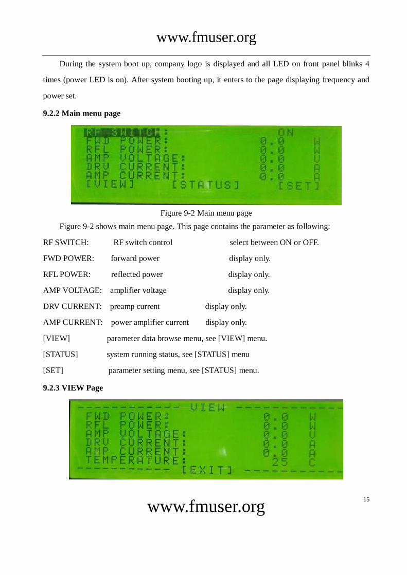
9.2.2 Main menu page
Figure 9-2 Main menu page
Figure 9-2 shows main menu page. This page contains the parameter as following:
RF SWITCH: RF switch control select between ON or OFF.
FWD POWER: forward power display only.
RFL POWER: reflected power display only.
AMP VOLTAGE: amplifier voltage display only.
DRV CURRENT: preamp current display only.
AMP CURRENT: power amplifier current display only.
[VIEW] parameter data browse menu, see [VIEW] menu.
[STATUS] system running status, see [STATUS] menu
[SET] parameter setting menu, see [STATUS] menu.
9.2.3 VIEW Page
www.fmuser.org
www.fmuser.org
16
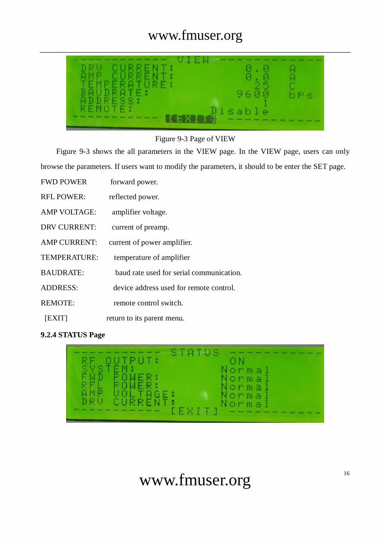
Figure 9-3 Page of VIEW
Figure 9-3 shows the all parameters in the VIEW page. In the VIEW page, users can only
browse the parameters. If users want to modify the parameters, it should to be enter the SET page.
FWD POWER: forward power.
RFL POWER: reflected power.
AMP VOLTAGE: amplifier voltage.
DRV CURRENT: current of preamp.
AMP CURRENT: current of power amplifier.
TEMPERATURE: temperature of amplifier
BAUDRATE: baud rate used for serial communication.
ADDRESS: device address used for remote control.
REMOTE: remote control switch.
[EXIT] return to its parent menu.
9.2.4 STATUS Page
www.fmuser.org
www.fmuser.org
17
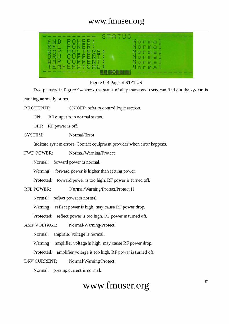
Figure 9-4 Page of STATUS
Two pictures in Figure 9-4 show the status of all parameters, users can find out the system is
running normally or not.
RF OUTPUT: ON/OFF; refer to control logic section.
ON: RF output is in normal status.
OFF: RF power is off.
SYSTEM: Normal/Error
Indicate system errors. Contact equipment provider when error happens.
FWD POWER: Normal/Warning/Protect
Normal: forward power is normal.
Warning: forward power is higher than setting power.
Protected: forward power is too high, RF power is turned off.
RFL POWER: Normal/Warning/Protect/Protect H
Normal: reflect power is normal.
Warning: reflect power is high, may cause RF power drop.
Protected: reflect power is too high, RF power is turned off.
AMP VOLTAGE: Normal/Warning/Protect
Normal: amplifier voltage is normal.
Warning: amplifier voltage is high, may cause RF power drop.
Protected: amplifier voltage is too high, RF power is turned off.
DRV CURRENT: Normal/Warning/Protect
Normal: preamp current is normal.
www.fmuser.org
www.fmuser.org
18
Warning: preamp current is high, may cause RF power drop.
Protected: preamp current is too high, RF power is turned off.
AMP CURRENT: Normal/Warning/Protect
Normal: amplifier current is normal.
Warning: amplifier current is high, may cause RF power drop.
Protected: amplifier current is too high, RF power is turned off.
TEMPERATURE: Normal/Warning/Protect
Normal: temperature is normal.
Warning: temperature is high, may cause RF power drop.
Protected: temperature is too high, RF power is turned off.
[EXIT] return to its parent menu.
9.2.5 SET Page
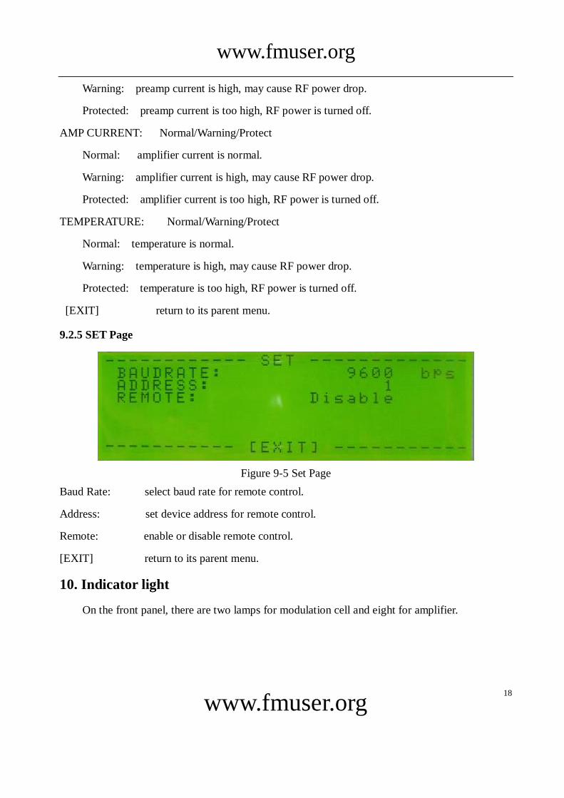
Figure 9-5 Set Page
Baud Rate: select baud rate for remote control.
Address: set device address for remote control.
Remote: enable or disable remote control.
[EXIT] return to its parent menu.
10. Indicator light
On the front panel, there are two lamps for modulation cell and eight for amplifier.
www.fmuser.org
www.fmuser.org
19
10.1 Lamp for Modulation Cell
10.1.1 Lamp for Power on
When this lamp is luminous, it means the power supply for modulation cell is normal.
10.1.2 Lamp for Video AGC
When video output is controlled by AGC, this lamp is light.
10.2 Lamp for Amplifier Cell
10.2.1 Lamp for Power on
When it is power on, the voltage of 5V is supplied normally, this green lamp is luminous.
10.2.2 Lamp for RF
When the RF SWITCH on the main menu is set to “ON”, this green lamp is light.
10.2.3 Lamp for Video
While output power is normal, this lamp is light.
10.2.4 Lamp for REMOTE
In the page of Set, if Remote is enabled, this yellow light is illuminant.
10.2.5 Lamp for TEMP
When the amplifier temperature is higher than 70℃, if temperature exceeds 85℃,it will
power off immediately.
10.2.6 Lamp for VSWR
If reflected power is higher than 2% of rated power, the lamp is light; higher than 4% of
power, it will decrease output power to decrease reflected power; when it is higher than 5%, it may
happen that: the software power off the output, or the hardware circuit switch off the power supply,
then power on again.
10.2.7 Lamp for GENERAL
If this lamp is light, it may happen that: forward power is more than 101% of rated power,
www.fmuser.org
www.fmuser.org
20
preamp current or amplifier current is higher than normal value.
if forward power is more than 110% of rated power, preamp current or amplifier current is too
much higher than normal value. it will shut down at once.
10.2.8 Lamp for RF MUTE
It means nothing for this mode of equipment.
11. Failure Check
11.1 Turn on the power supply, but the equipment doesn’t work
it may:
The fuse is broken: change the fuse;
The plug is not inserted tightly or contacted fault: insert the plug tightly.
11.2 No audio or video output
The source of audio or video signal is not connected: check the wire to ensure it has been
connected correctly.
11.3 Other Failure
If there is any other problem that can not be solved, please contact with Zhongchuan digital
equipment Co., Ltd.