zinc oxide surge arrester exlim r - abb ltd · zinc oxide surge arrester exlim r protection of...
TRANSCRIPT
80 Product information | ABB Surge Arresters — Buyer´s Guide
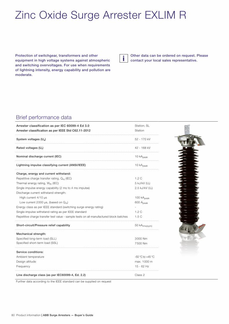
Zinc Oxide Surge Arrester EXLIM R
Protection of switchgear, transformers and other equipment in high voltage systems against atmospheric and switching overvoltages. For use when requirements of lightning intensity, energy capability and pollution are moderate.
Brief performance dataArrester classification as per IEC 60099-4 Ed 3.0
Arrester classification as per IEEE Std C62.11-2012
Station; SL
Station
System voltages (Us) 52 - 170 kV
Rated voltages (Ur) 42 - 168 kV
Nominal discharge current (IEC) 10 kApeak
Lightning impulse classifying current (ANSI/IEEE) 10 kApeak
Charge, energy and current withstand:
Repetitive charge transfer rating, Qrs (IEC)
Thermal energy rating, Wth (IEC)
Single impulse energy capability (2 ms to 4 ms impulse)
Discharge current withstand strength:
High current 4/10 µs
Low current 2 000 µs, (based on Qrs)
Energy class as per IEEE standard (switching surge energy rating)
Single-impulse withstand rating as per IEEE standard
Repetitive charge transfer test value - sample tests on all manufactured block batches
1.2 C
5 kJ/kV (Ur)
2.5 kJ/kV (Ur)
100 kApeak
600 Apeak
-
1.2 C
1.5 C
Short-circuit/Pressure relief capability 50 kArms(sym)
Mechanical strength:
Specified long-term load (SLL)Specified short-term load (SSL)
3 000 Nm
7 500 Nm
Service conditions:
Ambient temperature
Design altitude
Frequency
-50 °C to +45 °C
max. 1 000 m
15 - 62 Hz
Line discharge class (as per IEC60099-4, Ed. 2.2) Class 2
Further data according to the IEEE standard can be supplied on request
Other data can be ordered on request. Please contact your local sales representative.
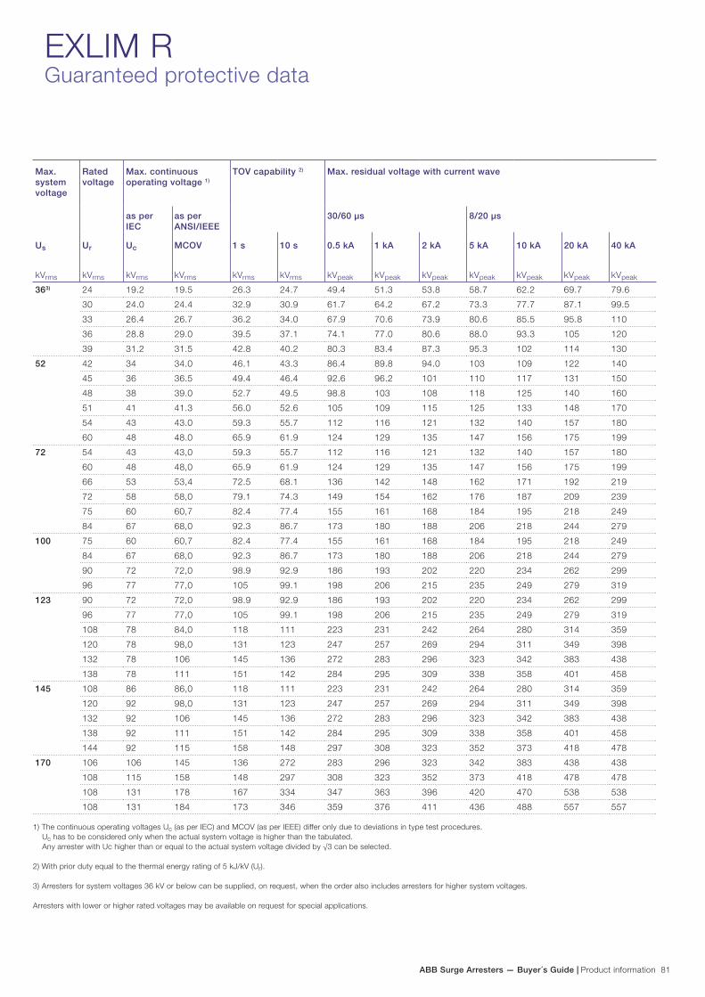
ABB Surge Arresters — Buyer´s Guide | Product information 81
EXLIM RGuaranteed protective data
Max. system voltage
Rated voltage
Max. continuous operating voltage 1)
TOV capability 2) Max. residual voltage with current wave
as per IEC
as per ANSI/IEEE
30/60 µs 8/20 µs
Us
kVrms
Ur
kVrms
Uc
kVrms
MCOV
kVrms
1 s
kVrms
10 s
kVrms
0.5 kA
kVpeak
1 kA
kVpeak
2 kA
kVpeak
5 kA
kVpeak
10 kA
kVpeak
20 kA
kVpeak
40 kA
kVpeak
363) 24 19.2 19.5 26.3 24.7 49.4 51.3 53.8 58.7 62.2 69.7 79.6
30 24.0 24.4 32.9 30.9 61.7 64.2 67.2 73.3 77.7 87.1 99.5
33 26.4 26.7 36.2 34.0 67.9 70.6 73.9 80.6 85.5 95.8 110
36 28.8 29.0 39.5 37.1 74.1 77.0 80.6 88.0 93.3 105 120
39 31.2 31.5 42.8 40.2 80.3 83.4 87.3 95.3 102 114 130
52 42 34 34.0 46.1 43.3 86.4 89.8 94.0 103 109 122 140
45 36 36.5 49.4 46.4 92.6 96.2 101 110 117 131 150
48 38 39.0 52.7 49.5 98.8 103 108 118 125 140 160
51 41 41.3 56.0 52.6 105 109 115 125 133 148 170
54 43 43.0 59.3 55.7 112 116 121 132 140 157 180
60 48 48.0 65.9 61.9 124 129 135 147 156 175 199
72 54 43 43,0 59.3 55.7 112 116 121 132 140 157 180
60 48 48,0 65.9 61.9 124 129 135 147 156 175 199
66 53 53,4 72.5 68.1 136 142 148 162 171 192 219
72 58 58,0 79.1 74.3 149 154 162 176 187 209 239
75 60 60,7 82.4 77.4 155 161 168 184 195 218 249
84 67 68,0 92.3 86.7 173 180 188 206 218 244 279
100 75 60 60,7 82.4 77.4 155 161 168 184 195 218 249
84 67 68,0 92.3 86.7 173 180 188 206 218 244 279
90 72 72,0 98.9 92.9 186 193 202 220 234 262 299
96 77 77,0 105 99.1 198 206 215 235 249 279 319
123 90 72 72,0 98.9 92.9 186 193 202 220 234 262 299
96 77 77,0 105 99.1 198 206 215 235 249 279 319
108 78 84,0 118 111 223 231 242 264 280 314 359
120 78 98,0 131 123 247 257 269 294 311 349 398
132 78 106 145 136 272 283 296 323 342 383 438
138 78 111 151 142 284 295 309 338 358 401 458
145 108 86 86,0 118 111 223 231 242 264 280 314 359
120 92 98,0 131 123 247 257 269 294 311 349 398
132 92 106 145 136 272 283 296 323 342 383 438
138 92 111 151 142 284 295 309 338 358 401 458
144 92 115 158 148 297 308 323 352 373 418 478
170 106 106 145 136 272 283 296 323 342 383 438 438
108 115 158 148 297 308 323 352 373 418 478 478
108 131 178 167 334 347 363 396 420 470 538 538
108 131 184 173 346 359 376 411 436 488 557 557
1) The continuous operating voltages Uc (as per IEC) and MCOV (as per IEEE) differ only due to deviations in type test procedures. Uc has to be considered only when the actual system voltage is higher than the tabulated. Any arrester with Uc higher than or equal to the actual system voltage divided by √3 can be selected.
2) With prior duty equal to the thermal energy rating of 5 kJ/kV (Ur).
3) Arresters for system voltages 36 kV or below can be supplied, on request, when the order also includes arresters for higher system voltages.
Arresters with lower or higher rated voltages may be available on request for special applications.

82 Technical information | ABB Surge Arresters — Buyer´s Guide
EXLIM RTechnical data for housings
Max. system voltage
Rated voltage
Housing Creepage distance
mm
External insulation *) Dimensions
Us
kVrms
Ur
kVrms
1.2/50 µs dry
kVpeak
50 Hz wet (60s)
kVrms
250/2500 µs wet
kVpeak
Mass
kg
Amax
mm
B
mm
C
mm
Fig.
52 42-60 CV052 1615 275 129 212 45 725 - - 1
72 54-75 CM072 1615 275 129 212 46 725 - - 1
54-84 CV072 2651 394 221 320 62 997 - - 1
100 75-96 CH100 2651 394 221 320 63 997 - - 1
84-96 CV100 3685 537 287 433 78 1268 - - 1
123 90-108 CM123 2651 394 221 320 64 997 - - 1
90-138 CH123 3685 537 287 433 81 1268 - - 1
90-96 CV123 4266 669 350 532 103 1697 600 300 3
108-138 CV123 4266 669 350 532 103 1697 - - 2
145 108-144 CH145 3685 537 287 433 82 1268 - - 1
108-144 CV145 5302 788 442 640 119 1969 600 300 3
170 132-144 CM170 3685 537 287 433 82 1268 - - 1
132-144 CH170 4266 669 350 532 105 1697 600 300 3
162-168 CH170 4266 669 350 532 105 1697 - - 2
132-168 CV170 5302 788 442 640 120 1969 600 300 3
Neutral-ground arresters52 30-36 CN052 1615 275 129 212 43 725 - - 1
72 42-54 CN072 1615 275 129 212 45 725 - - 1
100 60 CN100 1615 275 129 212 45 725 - - 1
123 72 CN123 1615 275 129 212 62 725 - - 1
84-108 CN123 2651 394 221 320 64 997 - - 1
120 CN123 3685 537 287 433 79 1268 - - 1
145 84 CN145 2651 394 221 320 62 997 - - 1
90-108 CN145 2651 394 221 320 64 997 - - 1
120 CN145 3685 537 287 433 79 1268 - - 1
170 96-108 CN170 2651 394 221 320 64 997 - - 1
120 CN170 3685 537 287 433 79 1268 - - 1
*) Sum of withstand voltages for empty units of arrester.
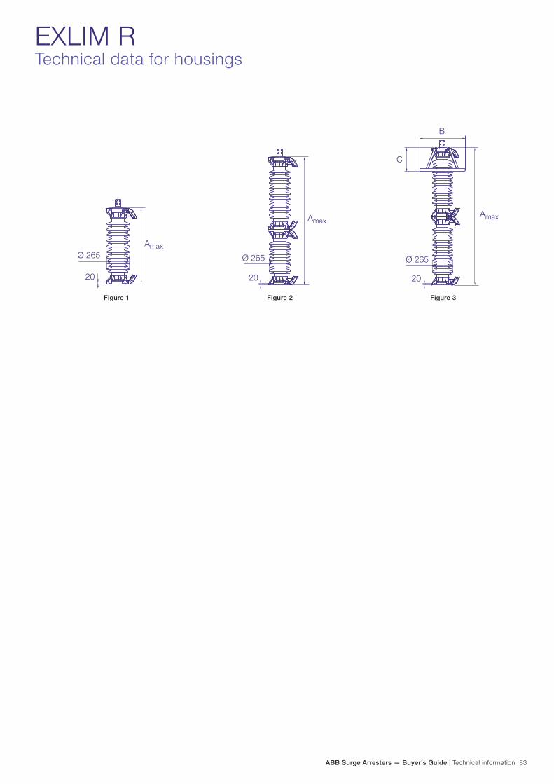
ABB Surge Arresters — Buyer´s Guide | Technical information 83
Figure 1 Figure 2 Figure 3
EXLIM RTechnical data for housings

84 Technical information | ABB Surge Arresters — Buyer´s Guide
EXLIM RAccessories
Line terminals
1HSA410 000-A
Aluminium
1HSA410 000-B
Aluminium flag with other
items in stainless steel
1HSA410 000-C
Aluminium
1HSA410 000-D
Stainless steel
Earth terminals
1HSA420 000-A
Stainless steel
1HSA420 000-B
Stainless steel
Drilling plans
Without insulating base
Aluminium
Insulating base
1HSA430 000-A
Epoxy resin
M12 bolts for connection to structure are not supplied by ABB. Required threaded grip length is 15-20 mm.
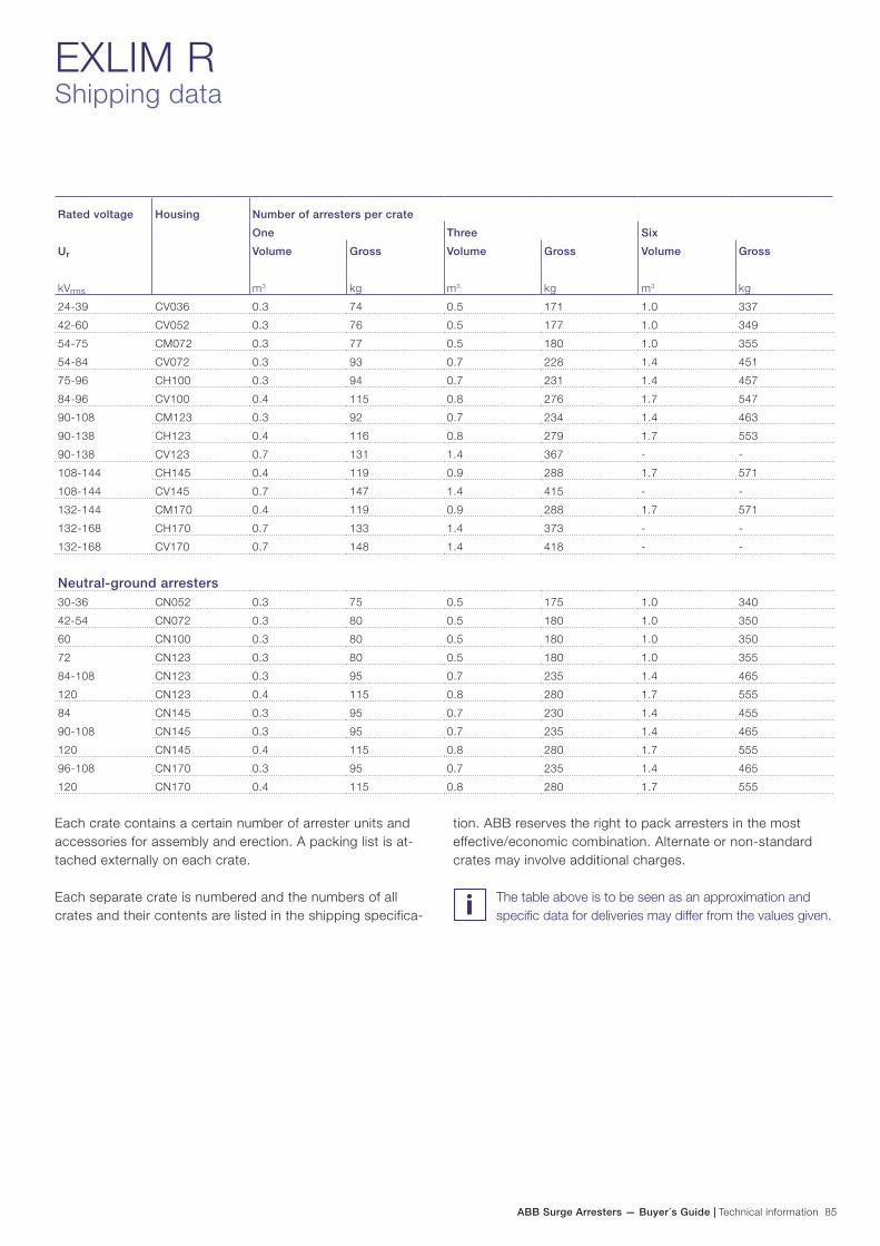
ABB Surge Arresters — Buyer´s Guide | Technical information 85
Rated voltage Housing Number of arresters per crate
One Three Six
Ur
kVrms
Volume
m3
Gross
kg
Volume
m3
Gross
kg
Volume
m3
Gross
kg
24-39 CV036 0.3 74 0.5 171 1.0 337
42-60 CV052 0.3 76 0.5 177 1.0 349
54-75 CM072 0.3 77 0.5 180 1.0 355
54-84 CV072 0.3 93 0.7 228 1.4 451
75-96 CH100 0.3 94 0.7 231 1.4 457
84-96 CV100 0.4 115 0.8 276 1.7 547
90-108 CM123 0.3 92 0.7 234 1.4 463
90-138 CH123 0.4 116 0.8 279 1.7 553
90-138 CV123 0.7 131 1.4 367 - -
108-144 CH145 0.4 119 0.9 288 1.7 571
108-144 CV145 0.7 147 1.4 415 - -
132-144 CM170 0.4 119 0.9 288 1.7 571
132-168 CH170 0.7 133 1.4 373 - -
132-168 CV170 0.7 148 1.4 418 - -
Neutral-ground arresters30-36 CN052 0.3 75 0.5 175 1.0 340
42-54 CN072 0.3 80 0.5 180 1.0 350
60 CN100 0.3 80 0.5 180 1.0 350
72 CN123 0.3 80 0.5 180 1.0 355
84-108 CN123 0.3 95 0.7 235 1.4 465
120 CN123 0.4 115 0.8 280 1.7 555
84 CN145 0.3 95 0.7 230 1.4 455
90-108 CN145 0.3 95 0.7 235 1.4 465
120 CN145 0.4 115 0.8 280 1.7 555
96-108 CN170 0.3 95 0.7 235 1.4 465
120 CN170 0.4 115 0.8 280 1.7 555
EXLIM RShipping data
Each crate contains a certain number of arrester units and accessories for assembly and erection. A packing list is at-tached externally on each crate.
Each separate crate is numbered and the numbers of all crates and their contents are listed in the shipping specifica-
tion. ABB reserves the right to pack arresters in the most effective/economic combination. Alternate or non-standard crates may involve additional charges.
The table above is to be seen as an approximation and specific data for deliveries may differ from the values given.