zip-bt-nfc (iphone)
TRANSCRIPT
1
7205
1-00
001.
C QUICK MOUNT VISUAL INSTRUCTION MANUAL
PKB and PMB Actuators
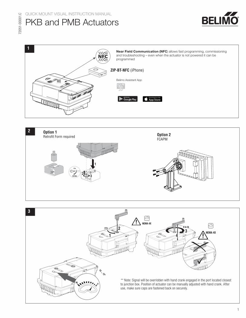
Near Field Communication (NFC) allows fast programming, commissioning and troubleshooting – even when the actuator is not powered it can be programmed
Belimo Assistant App
ZIP-BT-NFC (iPhone)
1
2 Option 1Retrofit Form required Option 2
FCAPM
3
23
1
4 x
6
25 Nm
3
10 ... 15°
090 ** Note: Signal will be overridden with hand crank engaged in the port located closest
to junction box. Position of actuator can be manually adjusted with hand crank. After use, make sure caps are fastened back on securely.
4
2
13
4NEMA 4X
9 in-lbNEMA 4X
4
2
13
4NEMA 4X
9 in-lbNEMA 4X
4
2
13
4NEMA 4X
9 in-lb

2
7205
1-00
001.
C QUICK MOUNT VISUAL INSTRUCTION MANUAL
PKB and PMB Actuators
45
№ 2
1
2 3
5
** Note: Only use conduit connector provided by Belimo. Make sure conduit connections are also securely connected.
1 45 in-lb*
2
* Note: Use brass knockout toremove plastic if included with glandset.
max. 3 ft-lbs
O-ring
PG11 Metric Thread
1/2” NPT
3 4
7
6
5
4 - 6mm
6 - 8mm
8 - 10mm
Use supplied conduit fittings. Failure to do somay result in water intrusion and void NEMA 4Xrating.
Do not remove!
Subj
ect t
o ch
ange
. © B
elim
o Ai
rcon
trols
(USA
), In
c.
3
7205
1-00
001.
C
WIRING DIAGRAMS
Floating Point
PKB and PMB Actuators
End SwitchesTemp Sensor
VDC / 4 to 20 mA
BACnet
24 to 240 VACor
24 to 125 VDC
N
L
Y1
Y2
N
Com
D +
D -
Com
Bacnet D +
D -
Notes:
0˚ to 90˚ default 85˚
41!
Meets cULus requirements without the need of an electrical ground connection.
5 Only connect common to neg. (-) leg of control circuits.
1 Provide overload protection and disconnect as required.
46Actuators may be controlled in parallel. Current draw and input impedance must be observed.
4 Two built-in auxiliary switches (2x SPDT), for end position indication, interlock control, fan startup, etc.
Universal Power Supply (UP) models can be suppliedwith 24 VAC up to 240 VAC, or 24 VDC up to 125 VDC.
Optional: end switch adjustment
On/Off
N
L
Y1
Y2
1UP 46!
Common
+ Hot
Input CCW (open)
Input CW (close)
24 to 240 VAC or
24 to 125 VDC
N
L
Y1
Y2
1UP 46!
Common
+ Hot
Input CCW (open)
Input CW (close)
24 to 240 VAC or
24 to 125 VDC
N
L
Y1
Y2
Common
+ Hot
Input CCW (open)
Input CW (close)
24 to 240 VAC or
24 to 125 VDC
1UP 461!
On/Off
N
L
Y1
Y2
N
5UP 46
24 to 240 VACor
24 to 125 VDC
-
+
Y3
U5
Com -
24 VDC Out
Y3 0 - 10 VDC**
U5/MP 0 - 10 VDC
1
**Control type, Direction and Fail position changes can be made via Belimo Assistant App, i.e. Floating or 4-20mA.
! During installation, testing, servicing and troubleshooting of this product, it may be necessary to work with live electrical components. Have a qualified licensed electrician or other individual who has been properly trained in handling live electrical components perform these tasks. Failure to follow all electrical safety precautions when exposed to live electrical components could result in death or serious injury.
Power
Status
5
6
Push-buttons and display
B
A
1
2
3
ope
n
ope
n
S2 S3
S1
S5 S6
S4
S5 S6
S4
10°
S2 S3
S5 S6
S4
S5 S6
S4
S1 S2 S3 S4 S5 S6
4
Disconnect power.
1 Gear disengagementOpen the manual override cover and insert the hand crank.Manual override is possible.
Manual override2
Turn the hand crank until indicates the desired switching position and then remove the crank.
A
B
3 Auxiliary switchOpen the auxiliary switch adjustment cover and properly seat the hand crank into the actuator. Turn the crank until the arrow points to the vertical line.
4 TerminalsConnect continuity tester to S4 + S5 or to S4 + S6.If the auxiliary switch should switch in the opposite direction, rotate the hand crank by 180˚.
5 LED Display Green6 LED Display Yellow Off: No power supply or malfunction, On: In operation Press button: Triggers test run, followed by standard mode.
6 LED Display YellowOff: Standard mode, On: Test run active.
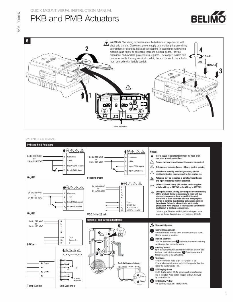
6
3
NEMA 4X
12 in-lb
2
1Power
Wire separator
4
№ 2
QUICK MOUNT VISUAL INSTRUCTION MANUAL
PKB and PMB Actuators
7
3
NEMA 4X
12 in-lb
2
1Power
Wire separator
4
2No
WARNING: The wiring technician must be trained and experienced withelectronic circuits. Disconnect power supply before attempting any wiringconnections or changes. Make all connections in accordance with wiringdiagrams and follow all applicable local and national codes. Providedisconnect and overload protection as required. Use copper, twisted pair,conductors only. If using electrical conduit, the attachment to the actuatormust be made with flexible conduit.