zodiak installation and service manual valley#zodiak#3.pdf · zodiak installation and service...
TRANSCRIPT

ZODIAKV I D E O P R O D U C T I O N S W I T C H E R
Installation and Service Manual
071812500F IRST PRINTING: SEPTEMBER 2001
Contacting Grass Valley Group
Copyright © Grass Valley Group. All rights reserved.
This document may not be copied, in whole or in part, or otherwise reproduced, except as specifically permitted under U.S. copyright law, without the prior written consent of Grass Valley Group, P.O. Box 599000, Nevada City, CA 95959-7900 USA. GRASS VALLEY GROUP is a registered trademark and Grass Valley is a trademark of Grass Valley Group. All registered trademarks and trademarks are prop-erty of their respective holders. Grass Valley Group products are covered by U.S. and foreign patents, issued and pending. Product options and specifications subject to change without notice. The informa-tion in this manual is furnished for informational use only, is subject to change without notice, and should not be construed as a commitment by Grass Valley Group. Grass Valley Group assumes no re-sponsibility or liability for any errors or inaccuracies that may appear in this publication.
Grass Valley Group Web Site
The www.grassvalleygroup.com web site offers the following:
Online User Documentation
– Current versions of product catalogs, brochures, data sheets, ordering guides, planning guides, manuals, and release notes in .pdf format can be downloaded.
FAQ Database
– Solutions to problems and troubleshooting efforts can be found by searching our Frequently Asked Questions (FAQ) database.
Software Downloads
– Software updates, drivers, and patches can be down-loaded.
Region Voice Fax Address Web Site
North America (800) 547-8949530-478-4148
(530) 478-3347 Grass Valley GroupP.O. Box 599000Nevada City, CA 95959-7900 USA
www.grassvalleygroup.com
Pacific Operations +852-2585-6688Support: 852-2585-6579
+852-2802-2996
U.K., Europe, Asia, Middle East +44 1753 218 777 +44 1753 218 757
France +33 1 45 29 73 00
Germany +49 221 1791 234 +49 221 1791 235

ContentPreface
About This Manual . . . . . . . . . . . . . . . . . . . . . . . . . . . . . . . . . . . . . . . . . . . . . . . . . . . . viiDocumentation Set . . . . . . . . . . . . . . . . . . . . . . . . . . . . . . . . . . . . . . . . . . . . . . . . . . vii
Regulatory NoticesCertifications and Compliances . . . . . . . . . . . . . . . . . . . . . . . . . . . . . . . . . . . . . . . . . ix
FCC Emission Control . . . . . . . . . . . . . . . . . . . . . . . . . . . . . . . . . . . . . . . . . . . . . . . ixCanadian EMC Notice of Compliance . . . . . . . . . . . . . . . . . . . . . . . . . . . . . . . . . . ixEN55103-1/2 Class A Warning . . . . . . . . . . . . . . . . . . . . . . . . . . . . . . . . . . . . . . . . ixFCC Emission Limits. . . . . . . . . . . . . . . . . . . . . . . . . . . . . . . . . . . . . . . . . . . . . . . . . . xCertification and Compliance . . . . . . . . . . . . . . . . . . . . . . . . . . . . . . . . . . . . . . . . . . x
Safety SummarySafety Terms and Symbols. . . . . . . . . . . . . . . . . . . . . . . . . . . . . . . . . . . . . . . . . . . . . . xi
Terms in This Manual . . . . . . . . . . . . . . . . . . . . . . . . . . . . . . . . . . . . . . . . . . . . . . . . xiTerms on the Product . . . . . . . . . . . . . . . . . . . . . . . . . . . . . . . . . . . . . . . . . . . . . . . . xiSymbols on the Product . . . . . . . . . . . . . . . . . . . . . . . . . . . . . . . . . . . . . . . . . . . . . . xii
Warnings . . . . . . . . . . . . . . . . . . . . . . . . . . . . . . . . . . . . . . . . . . . . . . . . . . . . . . . . . . . . xiiCautions . . . . . . . . . . . . . . . . . . . . . . . . . . . . . . . . . . . . . . . . . . . . . . . . . . . . . . . . . . . . xiii
Section 1 — System OverviewIntroduction . . . . . . . . . . . . . . . . . . . . . . . . . . . . . . . . . . . . . . . . . . . . . . . . . . . . . . . . . 1-1
Features . . . . . . . . . . . . . . . . . . . . . . . . . . . . . . . . . . . . . . . . . . . . . . . . . . . . . . . . . . . 1-12.5-M/E System Standard Features. . . . . . . . . . . . . . . . . . . . . . . . . . . . . . . . . . 1-13-M/E System Standard Features . . . . . . . . . . . . . . . . . . . . . . . . . . . . . . . . . . . 1-2Zodiak System Options. . . . . . . . . . . . . . . . . . . . . . . . . . . . . . . . . . . . . . . . . . . . 1-3
External Interfaces Supported . . . . . . . . . . . . . . . . . . . . . . . . . . . . . . . . . . . . . . . . 1-3System Components . . . . . . . . . . . . . . . . . . . . . . . . . . . . . . . . . . . . . . . . . . . . . . . . . . 1-4
Control Surface . . . . . . . . . . . . . . . . . . . . . . . . . . . . . . . . . . . . . . . . . . . . . . . . . . . . 1-4Main Panel . . . . . . . . . . . . . . . . . . . . . . . . . . . . . . . . . . . . . . . . . . . . . . . . . . . . . . 1-5Menu Panel . . . . . . . . . . . . . . . . . . . . . . . . . . . . . . . . . . . . . . . . . . . . . . . . . . . . . . 1-6
Main Panel Options. . . . . . . . . . . . . . . . . . . . . . . . . . . . . . . . . . . . . . . . . . . . . . . . . 1-7Remote Aux Panels . . . . . . . . . . . . . . . . . . . . . . . . . . . . . . . . . . . . . . . . . . . . . . . 1-7
Video Processor Frame . . . . . . . . . . . . . . . . . . . . . . . . . . . . . . . . . . . . . . . . . . . . . . 1-8Video Processor Power Supply . . . . . . . . . . . . . . . . . . . . . . . . . . . . . . . . . . . . . 1-9
Video Processor Frame Options . . . . . . . . . . . . . . . . . . . . . . . . . . . . . . . . . . . . . . 1-9Transform Engine Option. . . . . . . . . . . . . . . . . . . . . . . . . . . . . . . . . . . . . . . . . . 1-9RGB Color Correction . . . . . . . . . . . . . . . . . . . . . . . . . . . . . . . . . . . . . . . . . . . . . 1-9Chroma Keyers. . . . . . . . . . . . . . . . . . . . . . . . . . . . . . . . . . . . . . . . . . . . . . . . . . . 1-9
Zodiak Facility Example. . . . . . . . . . . . . . . . . . . . . . . . . . . . . . . . . . . . . . . . . . . . . . 1-10
Zodiak Installation and Service Manual iii

Content
Functional Overview . . . . . . . . . . . . . . . . . . . . . . . . . . . . . . . . . . . . . . . . . . . . . . . . . 1-11Video Signal Flow. . . . . . . . . . . . . . . . . . . . . . . . . . . . . . . . . . . . . . . . . . . . . . . . . . 1-11System Control . . . . . . . . . . . . . . . . . . . . . . . . . . . . . . . . . . . . . . . . . . . . . . . . . . . . 1-14
Section 2 — InstallationPre-Installation Procedures . . . . . . . . . . . . . . . . . . . . . . . . . . . . . . . . . . . . . . . . . . . . . 2-1
System Survey . . . . . . . . . . . . . . . . . . . . . . . . . . . . . . . . . . . . . . . . . . . . . . . . . . . . . . 2-1Line Voltage . . . . . . . . . . . . . . . . . . . . . . . . . . . . . . . . . . . . . . . . . . . . . . . . . . . . . . . . 2-1
Safety Requirements. . . . . . . . . . . . . . . . . . . . . . . . . . . . . . . . . . . . . . . . . . . . . . . . . . . 2-2Installation Tasks . . . . . . . . . . . . . . . . . . . . . . . . . . . . . . . . . . . . . . . . . . . . . . . . . . . . . 2-2Zodiak Control Surface . . . . . . . . . . . . . . . . . . . . . . . . . . . . . . . . . . . . . . . . . . . . . . . . 2-3
Removable Media Drives. . . . . . . . . . . . . . . . . . . . . . . . . . . . . . . . . . . . . . . . . . . . . 2-3Zip Drive. . . . . . . . . . . . . . . . . . . . . . . . . . . . . . . . . . . . . . . . . . . . . . . . . . . . . . . . . 2-4
Main Panel Installation . . . . . . . . . . . . . . . . . . . . . . . . . . . . . . . . . . . . . . . . . . . . . . . . 2-4Ventilation . . . . . . . . . . . . . . . . . . . . . . . . . . . . . . . . . . . . . . . . . . . . . . . . . . . . . . . . . 2-5Dimensions and Connector Layout . . . . . . . . . . . . . . . . . . . . . . . . . . . . . . . . . . . . 2-5Power Supply . . . . . . . . . . . . . . . . . . . . . . . . . . . . . . . . . . . . . . . . . . . . . . . . . . . . . . 2-7Cabling and Pinouts . . . . . . . . . . . . . . . . . . . . . . . . . . . . . . . . . . . . . . . . . . . . . . . . . 2-7
Main Panel Options . . . . . . . . . . . . . . . . . . . . . . . . . . . . . . . . . . . . . . . . . . . . . . . . . . . 2-82.5-M/E to 3-M/E Upgrade Kit . . . . . . . . . . . . . . . . . . . . . . . . . . . . . . . . . . . . . . . 2-8
Keycap and Keycap Film Label Replacement . . . . . . . . . . . . . . . . . . . . . . . . . . 2-9Remote Aux Panels. . . . . . . . . . . . . . . . . . . . . . . . . . . . . . . . . . . . . . . . . . . . . . . . . 2-11
24-Crosspoint Remote Aux Panels . . . . . . . . . . . . . . . . . . . . . . . . . . . . . . . . . . 2-1132-Crosspoint Remote Aux Panels . . . . . . . . . . . . . . . . . . . . . . . . . . . . . . . . . . 2-15
Menu Panel Installation. . . . . . . . . . . . . . . . . . . . . . . . . . . . . . . . . . . . . . . . . . . . . . . 2-17Ventilation . . . . . . . . . . . . . . . . . . . . . . . . . . . . . . . . . . . . . . . . . . . . . . . . . . . . . . . . 2-20Cabling and Pinouts . . . . . . . . . . . . . . . . . . . . . . . . . . . . . . . . . . . . . . . . . . . . . . . . 2-20
Video Processor Frame Installation . . . . . . . . . . . . . . . . . . . . . . . . . . . . . . . . . . . . . 2-21Power Supply . . . . . . . . . . . . . . . . . . . . . . . . . . . . . . . . . . . . . . . . . . . . . . . . . . . . . 2-23
Power Supply Installation . . . . . . . . . . . . . . . . . . . . . . . . . . . . . . . . . . . . . . . . . 2-24Power Supply Removal . . . . . . . . . . . . . . . . . . . . . . . . . . . . . . . . . . . . . . . . . . . 2-24
Video Processor Frame Options . . . . . . . . . . . . . . . . . . . . . . . . . . . . . . . . . . . . . . . . 2-242.5-M/E to 3-M/E Upgrade Kit . . . . . . . . . . . . . . . . . . . . . . . . . . . . . . . . . . . . . . 2-24
Module Insertion . . . . . . . . . . . . . . . . . . . . . . . . . . . . . . . . . . . . . . . . . . . . . . . . . 2-25Module Removal . . . . . . . . . . . . . . . . . . . . . . . . . . . . . . . . . . . . . . . . . . . . . . . . . 2-25
Cabling and Pinouts . . . . . . . . . . . . . . . . . . . . . . . . . . . . . . . . . . . . . . . . . . . . . . . . 2-26Zodiak Control Surface Cabling and Control . . . . . . . . . . . . . . . . . . . . . . . . . . . . 2-28
Cabling . . . . . . . . . . . . . . . . . . . . . . . . . . . . . . . . . . . . . . . . . . . . . . . . . . . . . . . . . . . 2-28Control . . . . . . . . . . . . . . . . . . . . . . . . . . . . . . . . . . . . . . . . . . . . . . . . . . . . . . . . . . . 2-29
Cable Polarity and Cross Over Button . . . . . . . . . . . . . . . . . . . . . . . . . . . . . . . 2-30LAN Requirements . . . . . . . . . . . . . . . . . . . . . . . . . . . . . . . . . . . . . . . . . . . . . . . . . 2-30
Ethernet Switches and Hubs . . . . . . . . . . . . . . . . . . . . . . . . . . . . . . . . . . . . . . . 2-31Video. . . . . . . . . . . . . . . . . . . . . . . . . . . . . . . . . . . . . . . . . . . . . . . . . . . . . . . . . . . . . 2-33
Inputs . . . . . . . . . . . . . . . . . . . . . . . . . . . . . . . . . . . . . . . . . . . . . . . . . . . . . . . . . . 2-33Outputs . . . . . . . . . . . . . . . . . . . . . . . . . . . . . . . . . . . . . . . . . . . . . . . . . . . . . . . . . 2-33Reference Input . . . . . . . . . . . . . . . . . . . . . . . . . . . . . . . . . . . . . . . . . . . . . . . . . . 2-33
Section 3 — ConfigurationIntroduction. . . . . . . . . . . . . . . . . . . . . . . . . . . . . . . . . . . . . . . . . . . . . . . . . . . . . . . . . . 3-1Basic Configuration Steps . . . . . . . . . . . . . . . . . . . . . . . . . . . . . . . . . . . . . . . . . . . . . . 3-1
iv Zodiak Installation and Service Manual

Content
Power Up . . . . . . . . . . . . . . . . . . . . . . . . . . . . . . . . . . . . . . . . . . . . . . . . . . . . . . . . . . . 3-1Power and Initialization Indications . . . . . . . . . . . . . . . . . . . . . . . . . . . . . . . . . 3-3
Network Configurations. . . . . . . . . . . . . . . . . . . . . . . . . . . . . . . . . . . . . . . . . . . . . 3-4Standalone Configuration. . . . . . . . . . . . . . . . . . . . . . . . . . . . . . . . . . . . . . . . . . 3-4Connecting to an Existing Network . . . . . . . . . . . . . . . . . . . . . . . . . . . . . . . . . 3-5
IP Addresses. . . . . . . . . . . . . . . . . . . . . . . . . . . . . . . . . . . . . . . . . . . . . . . . . . . . . . . 3-6Fundamental IP Routing Concept . . . . . . . . . . . . . . . . . . . . . . . . . . . . . . . . . . . 3-7Changing IP Addresses. . . . . . . . . . . . . . . . . . . . . . . . . . . . . . . . . . . . . . . . . . . . 3-7
Software Installation . . . . . . . . . . . . . . . . . . . . . . . . . . . . . . . . . . . . . . . . . . . . . . . . . 3-17Hardware Reset Procedures . . . . . . . . . . . . . . . . . . . . . . . . . . . . . . . . . . . . . . . . . . 3-17
Main Panel and Menu Panel Reset . . . . . . . . . . . . . . . . . . . . . . . . . . . . . . . . . . . 3-17Video Processor Frame Reset. . . . . . . . . . . . . . . . . . . . . . . . . . . . . . . . . . . . . . . . 3-18
Engineering Setups . . . . . . . . . . . . . . . . . . . . . . . . . . . . . . . . . . . . . . . . . . . . . . . . . . 3-19Source Definition . . . . . . . . . . . . . . . . . . . . . . . . . . . . . . . . . . . . . . . . . . . . . . . . . . 3-19
Direct Source Definition . . . . . . . . . . . . . . . . . . . . . . . . . . . . . . . . . . . . . . . . . . 3-20Output Configuration . . . . . . . . . . . . . . . . . . . . . . . . . . . . . . . . . . . . . . . . . . . . . . 3-21
Program and Preview Outputs . . . . . . . . . . . . . . . . . . . . . . . . . . . . . . . . . . . . 3-21Aux Bus Configuration . . . . . . . . . . . . . . . . . . . . . . . . . . . . . . . . . . . . . . . . . . . 3-22
Save Engineering Setups . . . . . . . . . . . . . . . . . . . . . . . . . . . . . . . . . . . . . . . . . . . 3-25Daily Setups . . . . . . . . . . . . . . . . . . . . . . . . . . . . . . . . . . . . . . . . . . . . . . . . . . . . . . . . 3-26Panel Adjustments . . . . . . . . . . . . . . . . . . . . . . . . . . . . . . . . . . . . . . . . . . . . . . . . . . 3-27
Lever Arm and Joystick Calibration . . . . . . . . . . . . . . . . . . . . . . . . . . . . . . . . . . 3-27Menu Panel Touch Screen Calibration . . . . . . . . . . . . . . . . . . . . . . . . . . . . . . . . 3-30
Touch Screen Calibration . . . . . . . . . . . . . . . . . . . . . . . . . . . . . . . . . . . . . . . . . 3-30Refresh Frequency Adjustment . . . . . . . . . . . . . . . . . . . . . . . . . . . . . . . . . . . . 3-30
Section 4 — MaintenanceIntroduction . . . . . . . . . . . . . . . . . . . . . . . . . . . . . . . . . . . . . . . . . . . . . . . . . . . . . . . . . 4-1Servicing Precautions . . . . . . . . . . . . . . . . . . . . . . . . . . . . . . . . . . . . . . . . . . . . . . . . . 4-1Main Panel Maintenance . . . . . . . . . . . . . . . . . . . . . . . . . . . . . . . . . . . . . . . . . . . . . . 4-2
Cleaning . . . . . . . . . . . . . . . . . . . . . . . . . . . . . . . . . . . . . . . . . . . . . . . . . . . . . . . . . . 4-2Replacing Circuit Boards . . . . . . . . . . . . . . . . . . . . . . . . . . . . . . . . . . . . . . . . . . . . 4-2
Crosspoint Switch Board . . . . . . . . . . . . . . . . . . . . . . . . . . . . . . . . . . . . . . . . . . 4-2M/E Switch Board . . . . . . . . . . . . . . . . . . . . . . . . . . . . . . . . . . . . . . . . . . . . . . . . 4-3Real Time Processor Board . . . . . . . . . . . . . . . . . . . . . . . . . . . . . . . . . . . . . . . . . 4-4
Power Supply Replacement . . . . . . . . . . . . . . . . . . . . . . . . . . . . . . . . . . . . . . . . . . 4-5Fuse Replacement . . . . . . . . . . . . . . . . . . . . . . . . . . . . . . . . . . . . . . . . . . . . . . . . . . 4-6Button LED Replacement . . . . . . . . . . . . . . . . . . . . . . . . . . . . . . . . . . . . . . . . . . . . 4-6
Menu Panel Maintenance. . . . . . . . . . . . . . . . . . . . . . . . . . . . . . . . . . . . . . . . . . . . . . 4-7Cleaning . . . . . . . . . . . . . . . . . . . . . . . . . . . . . . . . . . . . . . . . . . . . . . . . . . . . . . . . . . 4-7
Video Processor Frame Maintenance . . . . . . . . . . . . . . . . . . . . . . . . . . . . . . . . . . . . 4-8Air Filter Cleaning. . . . . . . . . . . . . . . . . . . . . . . . . . . . . . . . . . . . . . . . . . . . . . . . . . 4-8Removing and Replacing Modules. . . . . . . . . . . . . . . . . . . . . . . . . . . . . . . . . . . . 4-9Field Upgrading of Modules . . . . . . . . . . . . . . . . . . . . . . . . . . . . . . . . . . . . . . . . . 4-9Power Supply Maintenance . . . . . . . . . . . . . . . . . . . . . . . . . . . . . . . . . . . . . . . . . . 4-9
Replacement Parts Lists . . . . . . . . . . . . . . . . . . . . . . . . . . . . . . . . . . . . . . . . . . . . . . . 4-9
Zodiak Installation and Service Manual v

Content
Appendix — Specifications
Index
vi Zodiak Installation and Service Manual

Preface
About This ManualThis Zodiak Installation and Service Manual provides installation, configura-tion, and service information for the Grass Valley Group Zodiak Video Pro-duction Switcher. This manual is designed for technical personnel responsible for installing and maintaining Zodiak systems.
Documentation SetThe standard Zodiak user documentation set consists of a:
■ User Manual,
■ Installation and Service Manual, and
■ Release Notes.
The User Manual contains background information about the Zodiak Video Production Switcher, and describes operating procedures. This manual can be used while learning about Zodiak, and for enhancing your basic knowl-edge of the system.
The Installation and Service Manual contains information about installing, configuring, and maintaining the system.
The Release Notes contain information about new features and system enhancements for a specific software version, and also includes software installation procedures. Always check the release notes for your current system software before operating your system.
Zodiak Installation and Service Manual vii

Preface
viii Zodiak Installation and Service Manual

Regulatory Notices
Certifications and Compliances
FCC Emission ControlThis equipment has been tested and found to comply with the limits for a Class A digital device, pursuant to Part 15 of the FCC Rules. These limits are designed to provide reasonable protection against harmful interference when the equipment is operated in a commercial environment. This equip-ment generates, uses, and can radiate radio frequency energy and, if not installed and used in accordance with the instruction manual, may cause harmful interference to radio communications. Operation of this equip-ment in a residential area is likely to cause harmful interference in which case the user will be required to correct the interference at his own expense. Changes or modifications not expressly approved by Grass Valley Group can affect emission compliance and could void the user’s authority to operate this equipment.
Canadian EMC Notice of ComplianceThis digital apparatus does not exceed the Class A limits for radio noise emissions from digital apparatus set out in the Radio Interfer-ence Regulations of the Canadian Department of Communications.
Le présent appareil numérique n’emet pas de bruits radioélectriques dépassant les limites applicables aux appareils numeriques de la classe A préscrites dans le Règlement sur le brouillage radioélectrique édicte par le ministère des Communications du Canada.
EN55103-1/2 Class A WarningFor products that comply with Class A. In a domestic environment this product may cause radio interference in which case the user may be required to take adequate measures.
Zodiak Installation and Service Manual ix

FCC Emission LimitsThis device complies with Part 15 of the FCC Rules. Operation is subject to the following two conditions: (1) This device may no cause harmful inter-ference, and (2) this device must accept any interference received, including interference that may cause undesirable operation.
Certification and ComplianceThis product has been evaluated for Electromagnetic Compatibility under the EN 55103-1/2 standards for Emissions and Immunity and meets the requirements for E4 environment.
This product complies with Class A (E4 environment). In a domestic envi-ronment this product may cause radio interference in which case the user may be required to take adequate measures.
This product has been evaluated and meets the following Safety Certifica-tion Standards:
Category Standard Designed/tested for compliance with:
Safety ANSI/UL60950 Safety of Information Technology Equipment, including Electrical Business Equipment (Third edition, 2000).
IEC 60950 Safety of Information Technology Equipment, including Electrical Business Equipment (Third edition, 1999).
CAN/CSA C22.2, No. 60950-00 Safety of Information Technology Equipment, including Electrical Business Equipment.
BSEN60950 Safety of Information Technology Equipment, including Electrical Business Equipment.
x Zodiak Installation and Service Manual

Safety SummaryRead and follow the important safety information below, noting especially those instructions related to risk of fire, electric shock or injury to persons. Additional specific warnings not listed here may be found throughout the manual.
WARNING Any instructions in this manual that require opening the equipment cover or enclosure are for use by qualified service personnel only. To reduce the risk of electric shock, do not perform any servicing other than that contained in the operating instructions unless you are qualified to do so.
Safety Terms and Symbols
Terms in This ManualSafety-related statements may appear in this manual in the following form:
WARNING Warning statements identify conditions or practices that may result in per-sonal injury or loss of life.
CAUTION Caution statements identify conditions or practices that may result in damage to equipment or other property, or which may cause equipment crucial to your business environment to become temporarily non-operational.
Terms on the ProductThe following terms may appear on the product:
DANGER — A personal injury hazard is immediately accessible as you read the marking.
WARNING — A personal injury hazard exists but is not immediately acces-sible as you read the marking.
CAUTION — A hazard to property, product, and other equipment is present.
Zodiak Installation and Service Manual xi

Symbols on the ProductThe following symbols may appear on the product:
WarningsThe following warning statements identify conditions or practices that can result in personal injury or loss of life.
Dangerous voltage or current may be present — Disconnect power and remove battery (if applicable) before removing protective panels, soldering, or replacing components.
Do not service alone — Do not internally service this product unless another person capable of rendering first aid and resuscitation is present.
Remove jewelry — Prior to servicing, remove jewelry such as rings, watches, and other metallic objects.
Avoid exposed circuitry — Do not touch exposed connections, components or circuitry when power is present.
Indicates that dangerous high voltage is present within the equipment enclosure that may be of sufficient magnitude to constitute a risk of electric shock.
Indicates that user, operator or service technician should refer to product manual(s) for important operating, mainte-nance, or service instructions.
This is a prompt to note fuse rating when replacing fuse(s). The fuse referenced in the text must be replaced with one having the ratings indicated.
Identifies a protective grounding terminal which must be connected to earth ground prior to making any other equip-ment connections.
Identifies an external protective grounding terminal which may be connected to earth ground as a supplement to an internal grounding terminal.
Indicates that static sensitive components are present which may be damaged by electrostatic discharge. Use anti-static procedures, equipment and surfaces during servicing.
xii Zodiak Installation and Service Manual
Use proper power cord — Use only the power cord supplied or specified for this product.
Ground product — Connect the grounding conductor of the power cord to earth ground.
Operate only with covers and enclosure panels in place — Do not operate this product when covers or enclosure panels are removed.
Use correct fuse — Use only the fuse type and rating specified for this product.
Use only in dry environment — Do not operate in wet or damp conditions.
Use only in non-explosive environment — Do not operate this product in an explosive atmosphere.
High leakage current may be present — Earth connection of product is essential before connecting power.
Dual power supplies may be present — Be certain to plug each power supply cord into a separate branch circuit employing a separate service ground. Disconnect both power supply cords prior to servicing.
Double pole neutral fusing — Disconnect mains power prior to servicing.
Use proper lift points — Do not use door latches to lift or move equipment.
Avoid mechanical hazards — Allow all rotating devices to come to a stop before servicing.
CautionsThe following caution statements identify conditions or practices that can result in damage to equipment or other property
Use correct power source — Do not operate this product from a power source that applies more than the voltage specified for the product.
Use correct voltage setting — If this product lacks auto-ranging power sup-plies, before applying power ensure that the each power supply is set to match the power source.
Provide proper ventilation — To prevent product overheating, provide equip-ment ventilation in accordance with installation instructions.
Use anti-static procedures — Static sensitive components are present which may be damaged by electrostatic discharge. Use anti-static procedures, equipment and surfaces during servicing.
Zodiak Installation and Service Manual xiii

Do not operate with suspected equipment failure — If you suspect product damage or equipment failure, have the equipment inspected by qualified service personnel.
Ensure mains disconnect — If mains switch is not provided, the power cord(s) of this equipment provide the means of disconnection. The socket outlet must be installed near the equipment and must be easily accessible. Verify that all mains power is disconnected before installing or removing power supplies and/or options.
Route cable properly — Route power cords and other cables so that they ar not likely to be damaged. Properly support heavy cable bundles to avoid con-nector damage.
Use correct power supply cords — Power cords for this equipment, if provided, meet all North American electrical codes. Operation of this equipment at voltages exceeding 130 VAC requires power supply cords which comply with NEMA configurations. International power cords, if provided, have the approval of the country of use.
Use correct replacement battery — This product may contain batteries. To reduce the risk of explosion, check polarity and replace only with the same or equivalent type recommended by manufacturer. Dispose of used bat-teries according to the manufacturer’s instructions.
Troubleshoot only to board level — Circuit boards in this product are densely populated with surface mount technology (SMT) components and applica-tion specific integrated circuits (ASICS). As a result, circuit board repair at the component level is very difficult in the field, if not impossible. For war-ranty compliance, do not troubleshoot systems beyond the board level.
xiv Zodiak Installation and Service Manual

Section 1System Overview
IntroductionThe Zodiak Video Production Switcher is optimized for mobile, post-pro-duction and broadcast facilities that need compact, easy to use, highly cre-ative, real-time tools for video switching, effects creation and run-time device control. Powerful digital video switching, mixing, and keying with E-MEM are standard features of Zodiak, in addition to internal Still Store capability.
The switcher is available in 2.5-M/E or 3-M/E models with or without Transform Engines (internal DVEs). Zodiak’s architecture provides an easy upgrade path from a 2.5-M/E to a 3-M/E; requiring the addition of a M/E module and power supply to the Video Processor frame and keycap changes to the Main panel. Reduced frame processor size (7 RU) and power consumption along with a smaller panel, sized to replace older analog Grass Valley Group switchers, make this switcher system an ideal replace-ment or addition to any existing or new facility.
Features
2.5-M/E System Standard FeaturesThe standard features for the 2.5-M/E system are:
■ 64 auto-timed SMPTE 259M inputs (configured as single inputs or video/key pairs),
■ Nine Aux buses plus switched preview — up to four Aux buses can be utilized for two Effects Send pairs,
■ 24 Source Selection buttons including Shift on each M/E, Key, PWV/AUX and PGM/PST bus rows,
■ Program and preview outputs per M/E,
■ Look ahead and other preview modes configured per each M/E,
■ Two full M/Es each with dedicated E-MEM (100 registers),
Zodiak Installation and Service Manual 1-1

Section 1 — System Overview
■ One Utility bus per full M/E for video in borders, video wipe patterns, or masking,
■ Four full function keyers with dedicated key controls per M/E,
■ Two complex and four simple (in each keyer) wipe generators per M/E,
■ Solarization, posterization, mosaic capabilities and YUV color correc-tion as part of the video processors on each full M/E bus,
■ Input freeze for each M/E key source and fill buses,
■ PGM and PST buses with E-MEM, Downstream Keyers (DSK) with three simple linear or luminance keyers, and programmable Clean Feed,
■ One pair of floating Chroma Keyers for use on any full-function keyer,
■ 100 frame Still Store,
■ Redundant power supplies for the Main panel and Video Processor frame,
■ Four optional Transform Engines (internal DVEs) each on M/E 1 and M/E 2,
■ Hot swapable Video Processor frame modules (including frame power supplies)
■ Touch Screen Menu Display, and
■ CD-ROM (internal to the Menu panel), external USB-powered Zip drive and two Floppy drives (one in the Main panel and one in the Video Processor frame).
3-M/E System Standard FeaturesThe standard features for the 3-M/E model are the same as the 2.5-M/E system in addition to the following:
■ A third full M/E (replacing PGM/PST) with two complex and four simple wipes and four full function keyers plus three linear DSK keyers, and
■ 13 Aux buses total plus switched Preview — up to eight Aux buses can be utilized for four Effects Send pairs.
1-2 Zodiak Installation and Service Manual

Introduction
Zodiak System OptionsThe options listed below are for all models of Zodiak, except those dedi-cated to M/E 3. Selected sets of options may be combined into packages for initial purchase. Individual options can be purchased and added to a Zodiak system at a later time. Some Zodiak system options contain hard-ware components and some are software enabled.
The options are:
■ Upgrade Kit (2.5-M/E only) adds a third full M/E (replacing PGM/PST) by changing keycaps to the Main panel, and installing a M/E module (M/E 3) and additional Video Processor frame power supply to the Video Processor frame,
■ RGB Color Correction for all keyer, background, and utility buses on M/E 1, M/E 2, and M/E 3 (3-M/E only),
■ Additional floating Chroma Key pairs for use on any full-function keyer,
■ Net Central II SNMP Agent,
■ Spare Video Processor frame power supply (for upgrade from 2.5-M/E to a 3-M/E system),
■ Four Transform Engines (internal DVEs) each for M/E 1, M/E 2 and M/E 3 (3-M/E only), and
■ 24– and 32–Crosspoint Remote Aux panels.
External Interfaces SupportedAll Zodiak systems have the following control interfaces:
■ Ethernet Facility LAN connections allowing error reporting and upload/download capability for configurations, E-MEMs and images,
■ GPI interface with eight inputs and eight outputs,
■ 32 programmable tally contact closures and serial tally,
■ Two USB ports on the Menu panel (one connecting to the external Zip drive, and one spare),
■ Six RS-422 serial ports for interfacing to 24- and 32-Crosspoint Remote Aux panels, Peripheral Bus II devices, edit controllers and CPL for external DVE (Krystal, GVeous) interface.
Zodiak Installation and Service Manual 1-3
Section 1 — System Overview
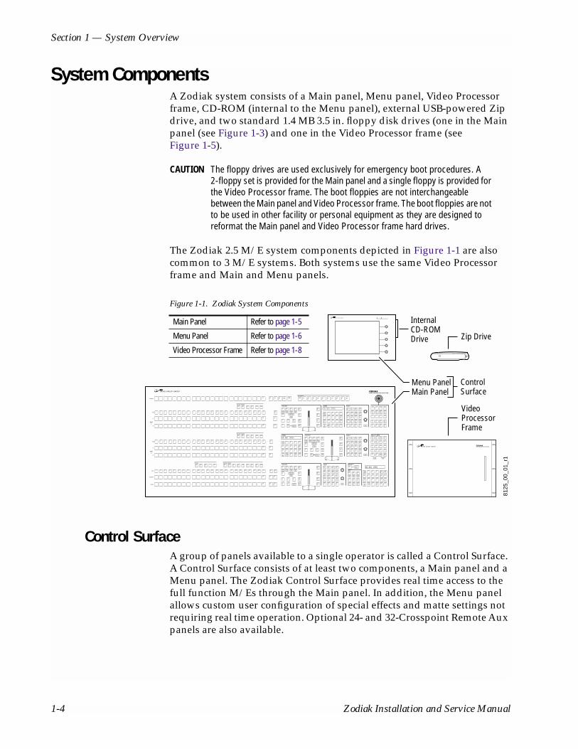
System ComponentsA Zodiak system consists of a Main panel, Menu panel, Video Processor frame, CD-ROM (internal to the Menu panel), external USB-powered Zip drive, and two standard 1.4 MB 3.5 in. floppy disk drives (one in the Main panel (see Figure 1-3) and one in the Video Processor frame (see Figure 1-5).
CAUTION The floppy drives are used exclusively for emergency boot procedures. A 2-floppy set is provided for the Main panel and a single floppy is provided for the Video Processor frame. The boot floppies are not interchangeable between the Main panel and Video Processor frame. The boot floppies are not to be used in other facility or personal equipment as they are designed to reformat the Main panel and Video Processor frame hard drives.
The Zodiak 2.5 M/E system components depicted in Figure 1-1 are also common to 3 M/E systems. Both systems use the same Video Processor frame and Main and Menu panels.
Figure 1-1. Zodiak System Components
Control SurfaceA group of panels available to a single operator is called a Control Surface. A Control Surface consists of at least two components, a Main panel and a Menu panel. The Zodiak Control Surface provides real time access to the full function M/Es through the Main panel. In addition, the Menu panel allows custom user configuration of special effects and matte settings not requiring real time operation. Optional 24- and 32-Crosspoint Remote Aux panels are also available.
8125
_00_
01_r
1
InternalCD-ROM Drive Zip Drive
ControlSurface
Menu PanelMain Panel
Video ProcessorFrame
Key
A
B
M/E1
Key
A
B
M/E2
Key
Program
Pvw/Aux
Preset
DSK
Key Bus Delegate
Bus Delegate
Key Bus Delegate
Preview Key Bus Delegate
E-MEM Transition Keyers Master E-MEM
E-MEMTransition Keyers
Transition Keyers Fade to Black
RecallEnables
KeyframeEdit
On On On
Effects Send
Uncal
On
027
Key1
Key2
Key3
Key4
KeyPrior
Key1
DSKLink
Key1
Key1
Key1
TransPVW
Key1
Key1
PresetBlack
1 2 3 4 5 6 7 8 9 10 11 12 13 14 15 16 17 18 19 20 21 22 23 Shift
Shift
Shift
B0 001 OPEN
1 2 3 4 5 6 7 8 9 10 11 12 13 14 15 16 17 18 19 20 21 22 23 Shift
Shift
Shift
Key1
Key2
Key3
Key4
Utility Macro
1 2 3 4 5 6 7 8 9 10 11 12 13 14 15 16 17 18 19 20 21 22 23 Shift
Shift
Shift
Key1
Key2
Key3
Key4
Utility Macro
Key 1Mix
Key 4Mix
Key 3Mix
Key 2Mix
TransRate
0 Enter
EffectDis
1 2 3 Bank1
Seq 4 5 6 Bank0
7 8 9 RunLockLearn
Bank
Undo•
Key1
LinKey
Video Key
MatteFill
IntDPM
Key2
LumKey
FreezeKey
FreezeFill
ExtDPM
Key3
ChrKey
Split
InhibitMask
KeyInvert
Key4
PresetPattrn
KeyOver
ForceMask
ShowKey
B0 001 OPEN
B0 001 OPEN
M/E2
M/E2
M/E2
032
On On On
Effects Send
Uncal
On
Key1
Key2
Key3
Key4
KeyPrior
Bkgd DSKLink
Mix Wipe UserTrans
TransPVW
Cut AutoTrans
PresetBlack
TransRate
0 Enter
EffectDis
1 2 3 Bank1
Seq 4 5 6 Bank0
7 8 9 RunLockLearn
Bank
Undo•
Key 1Mix
Key 4Mix
Key 3Mix
Key 2Mix
Key1
LinKey
Video Key
MatteFill
IntDPM
Key2
LumKey
FreezeKey
FreezeFill
ExtDPM
Key3
ChrKey
Split
InhibitMask
KeyInvert
Key4
PresetPattrn
KeyOver
ForceMask
ShowKey
Key 1Mix
Key 4Mix
Key 3Mix
Key 2Mix
Key1
LinKey
Video Key
MatteFill
IntDPM
Key2
LumKey
FreezeKey
FreezeFill
ExtDPM
Key3
ChrKey
Split
InhibitMask
KeyInvert
Key4
PresetPatter
KeyOver
ForceMask
ShowKey
Key1
M/E1
X
KeySource
Locate
Key2
M/E2
Y
KeyWipe
Size
Key3
M/E3
Z
BoxMask
Rotate
Key4
ExtDPM
Center
PriWipe
Menu
DSK1
DSK2
DSK3
DSK 1Cut
DSK 2Cut
DSK 3Cut
DSK 1Mix
DSK 2Mix
DSK 3Mix
TransRate
0 Enter
EffectDis
1 2 3 Bank1
Seq 4 5 6 Bank0
7 8 9 StopNextKF
Run
Re-wind
Rev
HoldInput
LockLearn
Bank
Undo•
AutoRecall
AutoRun
ClearWk Bfr
Go ToKF
M/E1
ExtDPM
Prev Next
M/E2
Misc1
Mod Paste
M/E3
Misc2
Cut Copy
DSK Misc3
InsertBefore
InsertAfter
PVW Aux1
Aux2
Aux3
Aux4
Aux5
Aux6
Aux7
Aux8
Aux9
Aux10
CleanFeed
PGMShift M/E1
M/E2
M/E2
M/E2
M/E2
On On On
Effects Send
Uncal
On
015
Key1
Key2
Key3
Key4
KeyPrior
Bkgd DSKLink
Mix Wipe UserTrans
TransPVW
Cut AutoTrans
PresetBlack On
On
On
On On On
M/E1
M/E1
M/E1
M/E1
M/E1
M/E1
M/E2
M/E1
PvwPri
DSK MacroKey4
Key3
Key2
Key1
Utility DSK1
DSK2
DSK3
M/E3
M/E3
027Fade toBlack
Main Panel Refer to page 1-5
Menu Panel Refer to page 1-6
Video Processor Frame Refer to page 1-8
1-4 Zodiak Installation and Service Manual

System Components
Main PanelThe panel is organized into subpanels that contain groups of related con-trols (Figure 1-2).
The 3-M/E Main panel provides real time button, knob, and lever arm control of three full function mix/effects (PGM/PST with full M/E capa-bility). The panel is identical to the 2.5-M/E panel except for keyer and wipe functionality in the PGM/PST rows.
The 2.5-M/E Main panel provides real time button, knob, and lever arm control of two full function mix/effects and one PGM/PST with three simple Downstream Keyers (DSKs).
Figure 1-2. Zodiak Main Panel (2.5 and 3 M/E)
Connectors to the Zodiak Video Processor frame and to other components of the Zodiak Control Surface are located on the rear of the Main panel (Figure 2-7). The Main panel provides power to the separate Menu panel.
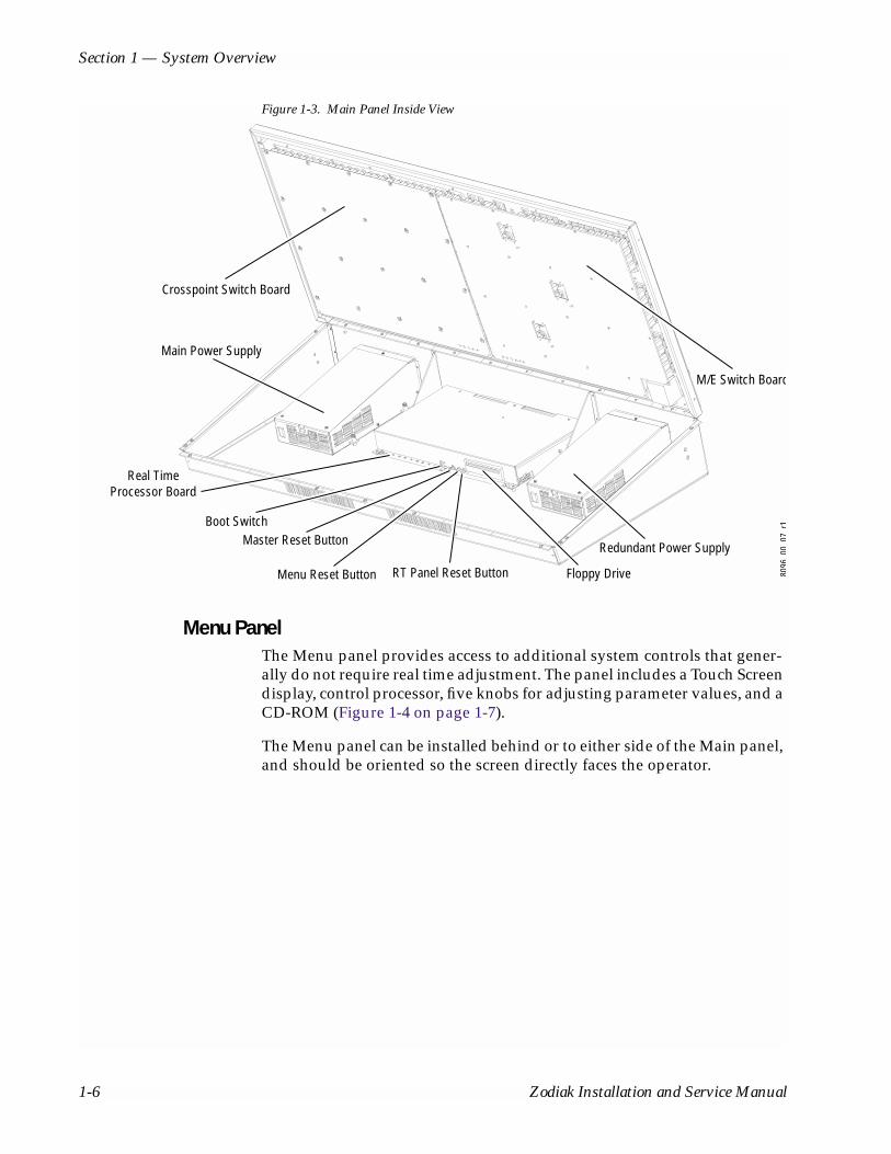
The Main panel power switches, reset buttons, and floppy drive are accessed by lifting the top of the Main panel (Figure 1-3).
8126
_00_
01_r
0
PVW/AUX Bus E-MEMSubpanels (3)
M/E1
Master E-MEMSubpanel
TransitionSubpanels (3)
Preview Subpanel
TransformSubpanel
M/E2
M/E3
PGMPST
Keyframe EditSubpanel
Key BusDelegation (3)
Fade to BlackSubpanel
KeyerSubpanels (3)
DSKSubpanel
Source Selection Key, M/E A/B, and PGM/PST
PVW/AUX Re-entries Aux Bus Delegation
Zodiak Installation and Service Manual 1-5
Section 1 — System Overview
Figure 1-3. Main Panel Inside View
Menu PanelThe Menu panel provides access to additional system controls that gener-ally do not require real time adjustment. The panel includes a Touch Screen display, control processor, five knobs for adjusting parameter values, and a CD-ROM (Figure 1-4 on page 1-7).
The Menu panel can be installed behind or to either side of the Main panel, and should be oriented so the screen directly faces the operator.
Main Power Supply
M/E Switch Board
Redundant Power Supply
Crosspoint Switch Board
Floppy DriveRT Panel Reset ButtonMenu Reset Button
Master Reset ButtonBoot Switch
Real TimeProcessor Board
8096
0007
r1
1-6 Zodiak Installation and Service Manual
System Components
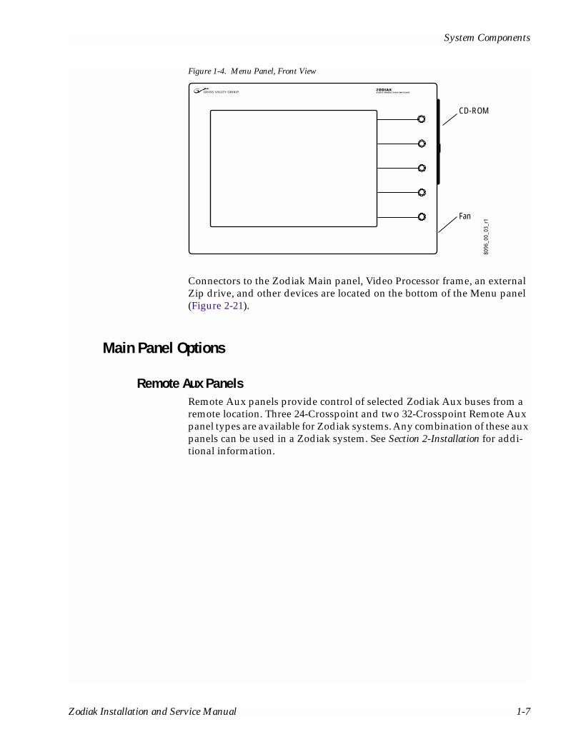
Figure 1-4. Menu Panel, Front View
Connectors to the Zodiak Main panel, Video Processor frame, an external Zip drive, and other devices are located on the bottom of the Menu panel (Figure 2-21).
Main Panel Options
Remote Aux PanelsRemote Aux panels provide control of selected Zodiak Aux buses from a remote location. Three 24-Crosspoint and two 32-Crosspoint Remote Aux panel types are available for Zodiak systems. Any combination of these aux panels can be used in a Zodiak system. See Section 2-Installation for addi-tional information.
8096
_00_
03_r
1Fan
CD-ROM
Zodiak Installation and Service Manual 1-7
Section 1 — System Overview
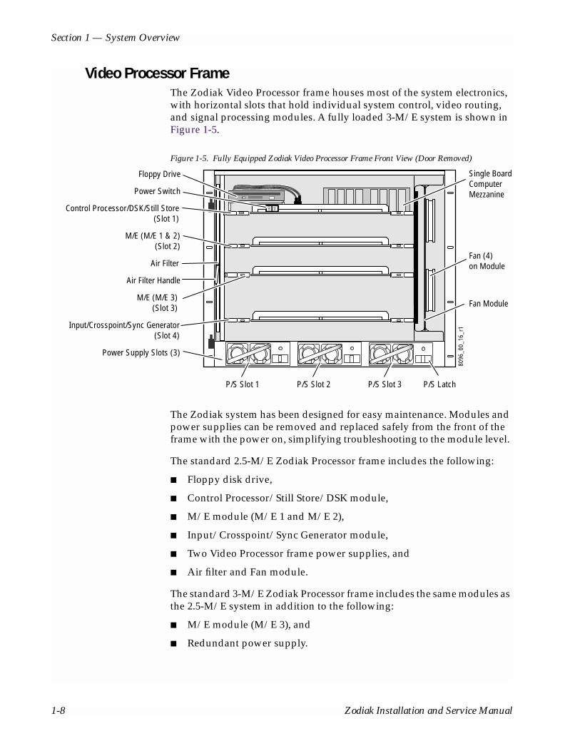
Video Processor FrameThe Zodiak Video Processor frame houses most of the system electronics, with horizontal slots that hold individual system control, video routing, and signal processing modules. A fully loaded 3-M/E system is shown in Figure 1-5.
Figure 1-5. Fully Equipped Zodiak Video Processor Frame Front View (Door Removed)
The Zodiak system has been designed for easy maintenance. Modules and power supplies can be removed and replaced safely from the front of the frame with the power on, simplifying troubleshooting to the module level.
The standard 2.5-M/E Zodiak Processor frame includes the following:
■ Floppy disk drive,
■ Control Processor/Still Store/DSK module,
■ M/E module (M/E 1 and M/E 2),
■ Input/Crosspoint/Sync Generator module,
■ Two Video Processor frame power supplies, and
■ Air filter and Fan module.
The standard 3-M/E Zodiak Processor frame includes the same modules as the 2.5-M/E system in addition to the following:
■ M/E module (M/E 3), and
■ Redundant power supply.
8096
_00_
16_r
1
ON
OFFControl Processor/DSK/Still Store(Slot 1)
M/E (M/E 1 & 2)(Slot 2)
Fan Module
Floppy Drive
M/E (M/E 3)(Slot 3)
Input/Crosspoint/Sync Generator(Slot 4)
Power Supply Slots (3)
Air Filter
Air Filter Handle
Fan (4)on Module
P/S Slot 2P/S Slot 1 P/S Slot 3 P/S Latch
Single BoardComputerMezzaninePower Switch
1-8 Zodiak Installation and Service Manual

System Components
The rear of the Zodiak Processor frame (Figure 2-26) provides the refer-ence, video and system control connectors for the system.
Video Processor Power SupplyThe Zodiak Video Processor frame houses up to three slide-in modules rated at 400 watts each. (Figure 1-5 on page 1-8). Two hot-swappable power supply modules (primary and redundant) are standard with the 2.5-M/E system, and three power supply modules are standard with the 3-M/E system.
The power supplies load share such that a supply can fail and the Video Processor frame will continue to operate on the other supply/supplies.
It is recommended that each module’s AC input be connected to a separate AC supply circuit. Any module(s) for which a separate supply circuit is not available can be connected to an uninterrupted power supply (UPS).
Video Processor Frame Options
Transform Engine OptionThe Zodiak Transform Engine option available per keyer provides the fol-lowing internal DVE capability:
■ 2-D effects in 3-D space with perspective,
■ Page turn,
■ Border, outline, and extrude effects,
■ Independent drop shadow,
■ Glow and defocus effects, and
■ Output recursive effects (such as star trails and montage).
RGB Color CorrectionIn addition to the standard solarization, posterization, mosaic capabilities and YUV color correction, RGB color correction can be added to all M/E buses (background, keyer, and utility).
Chroma KeyersIn addition to the two standard chroma keyers, optional floating chroma keyers may be added to the system.
Zodiak Installation and Service Manual 1-9

Section 1 — System Overview
Zodiak Facility ExampleA basic facility configuration example of a Zodiak system is shown in Figure 1-6. Numerous types of sources can be fed to the Video Processor frame. Each M/E, Keyer and Utility bus has internal video processing capability to correct color (including optional RGB color correction) and add effects. In addition to the optional internal Transform Engine DVE capabilities available on each keyer, this facility also utilizes an external DPM system configured for Effects Send.
Figure 1-6. Basic Facility Configuration Example
ProgramMonitor
PreviewMonitor
OtherMonitors
Program Out
Master Control/Transmitter
Video/Key (Effects Send)
Cam 1
Cam 2
Cam 3
Video/Key (Effects Return)
Synchronous Serial (CPL)
Reference Black
Aux Bus Outputs
8096
_00_
18_r
2
Zodiak Main Control Surface
Zodiak Control
MonitorMonitor
ZodiakVideoProcessorFrame
DPM1
VTR
1Compatible DVEs: Krystal, GVeous/Dveous
Video or Key SignalControl Line
MenuPanel
Main Panel
Men
u LA
N
Pane
l LAN
ProfileVDR
CharacterGenerator
Router
TSG
Paint System
Analog VTR
Video/Key
Video/Key
8900Series
DA
1-10 Zodiak Installation and Service Manual
Functional Overview
Functional Overview
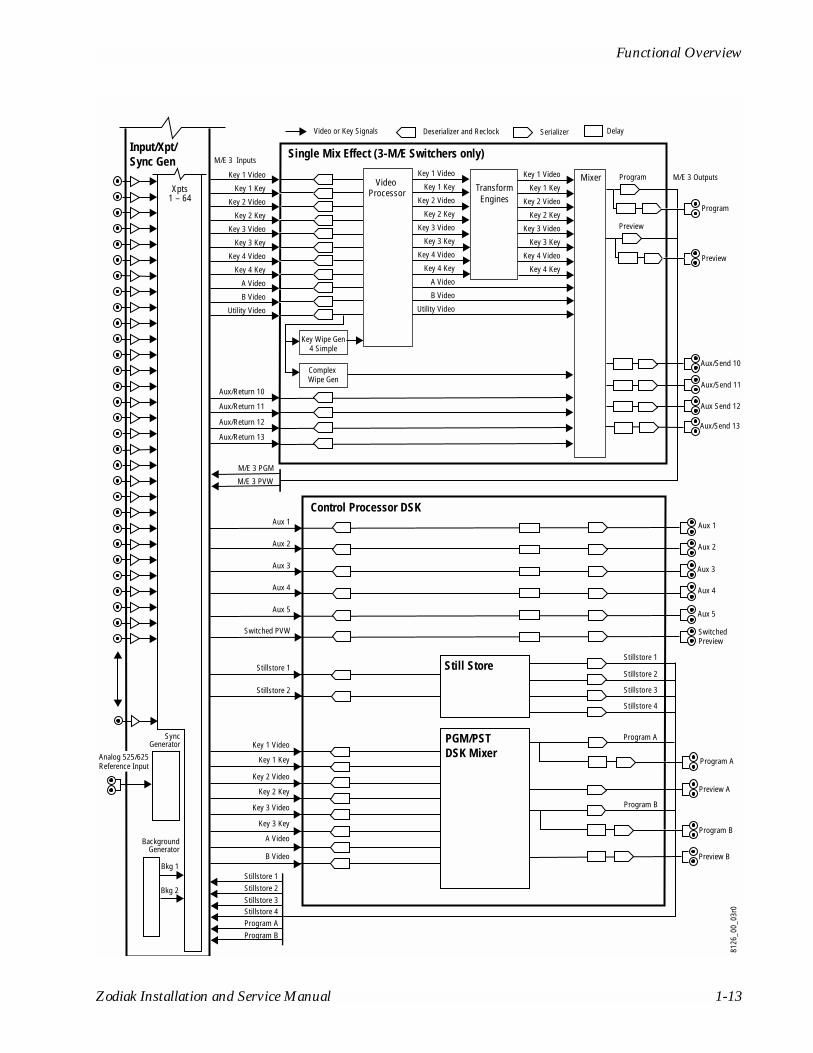
Video Signal FlowThe basic system architecture (Figure 1-7) of the Zodiak system has been designed for operational flexibility. For example, all the outputs from every M/E and the PGM/PST are routed back to the video crosspoint matrix, making all these signals accessible to the entire system.
The 2.5-M/E system has two full M/Es and a PGM/PST with DSK. The 3-M/E system has three full M/Es in addition to three simple DSKs and the ability to link DSK keys to any M/E.
The 64 video inputs to the Video Processor frame can be mapped to any of the 46 crosspoint buttons (23 unshifted and 23 shifted sources). Inter-nally-generated black and two backgrounds are also available sources, as are the four Still Store outputs. This source-to-button mapping is done through a Touch Screen menu and can be stored as a user profile for any number of individual users. Button mapping is the same on all buses.
The selected video on each bus is deserialized and reclocked before entering the video processing circuitry. Video processing is available for each separate M/E background, Key, and Utility bus, providing built-in solarization, posterization and mosaic effects. In addition, contrast, bright-ness, and hue can be adjusted on a bus-by-bus basis.
Each full M/E has four full-function keyers with optional internal Trans-form Engine effects. Each keyer has access to its own simple wipe generator as well as a pair of standard floating chroma keyers which may be assigned to any keyers in the system. Two complex wipe generator serves each M/E, providing a wide range of wipe choices with modulation, rotation and multiplication of each one. Wipes signals can also be taken from the Utility bus on each M/E.
The outputs from each M/E Program and Preview are fed to dedicated BNCs and sent back to the crosspoint circuitry for reentry selection in the other M/Es. Either Program/Preset output can be programmed as a clean feed output or with any combination of DSK 1, 2 and 3 keyers active.
Nine Aux buses are available in the 2.5-M/E system; thirteen in the 3-M/E system. The Aux bus outputs can be utilized in a number of ways, including configuration as Effects Send pairs for interfacing to external digital effects systems.
Zodiak Installation and Service Manual 1-11

Section 1 — System Overview
Figure 1-7. Simplified Video Flow Diagram
8126
_00_
01_r
0
Dual Mix EffectInput/Xpt/Sync Gen
Aux/Return 6
M/E 1 PGMM/E 1 PVWM/E 2 PGMM/E 2 PVW
M/E 1 Inputs
M/E 1 Outputs
M/E 2 Outputs
Key 1 Video
Key 1 Key
Key 2 Video
Key 2 Key
Key 3 Video
Key 3 Key
Key 4 Video
Key 4 Key
A Video
B Video
Utility Video
Key 1 Video
Key 1 Key
Key 2 Video
Key 2 Key
Key 3 Video
Key 3 Key
Key 4 Video
Key 4 Key
Key 1 Video
Key 1 Key
Key 2 Video
Key 2 Key
Key 3 Video
Key 3 Key
Key 4 Video
Key 4 Key
A Video
B Video
Utility Video
M/E 2 Inputs
Key 1 Video
Key 1 Key
Key 2 Video
Key 2 Key
Key 3 Video
Key 3 Key
Key 4 Video
Key 4 Key
A Video
B Video
Utility Video
Deserializer and Reclock Serializer Delay1Video or Key Signals
Video Processor
TransformEngines
Mixer
Key Wipe Gen4 Simple
Complex Wipe Gen
Program
Program
Preview
Preview
Key 1 Video
Key 1 Key
Key 2 Video
Key 2 Key
Key 3 Video
Key 3 Key
Key 4 Video
Key 4 Key
Key 1 Video
Key 1 Key
Key 2 Video
Key 2 Key
Key 3 Video
Key 3 Key
Key 4 Video
Key 4 Key
A Video
B Video
Utility Video
Video Processor
TransformEngines
Aux/Return 7
Aux/Return 8
Aux/Return 9
Key Wipe Gen4 Simple
Complex Wipe Gen
Program
Program
Preview
Preview
Aux/Send 6
Aux/Send 7
Aux Send 8
Aux/Send 9
11
Xpts1 – 64
1-12 Zodiak Installation and Service Manual
Functional Overview
Control Processor DSK
Input/Xpt/Sync Gen
Deserializer and Reclock Serializer DelayVideo or Key Signals
Program A
Program A
Aux 1 Aux 1
Aux 2 Aux 2
Aux 3 Aux 3
Aux 4 Aux 4
Aux 5 Aux 5
Switched PVW
Stillstore 1
Key 1 Video
Key 1 Key
Key 2 Video
Key 2 Key
Key 3 Video
Key 3 Key
A Video
B Video
Stillstore 1
Stillstore 2
Stillstore 3
Stillstore 4
Stillstore 2
SwitchedPreview
Still Store
Preview A
Preview B
Program B
Program B
Stillstore 1
BackgroundGenerator
SyncGenerator
Stillstore 2Stillstore 3Stillstore 4Program AProgram B
PGM/PST DSK Mixer
Bkg 1
Bkg 2
Single Mix Effect (3-M/E Switchers only)
M/E 3 Outputs
M/E 3 Inputs
Key 1 Video
Key 1 Key
Key 2 Video
Key 2 Key
Key 3 Video
Key 3 Key
Key 4 Video
Key 4 Key
A Video
B Video
Utility Video
Key 1 Video
Key 1 Key
Key 2 Video
Key 2 Key
Key 3 Video
Key 3 Key
Key 4 Video
Key 4 Key
Key 1 Video
Key 1 Key
Key 2 Video
Key 2 Key
Key 3 Video
Key 3 Key
Key 4 Video
Key 4 Key
A Video
B Video
Utility Video
Video Processor Transform
Engines
Mixer
Key Wipe Gen4 Simple
Complex Wipe Gen
Program
Program
Preview
Preview
Aux/Send 10
Aux/Send 11
Aux Send 12
Aux/Send 13
M/E 3 PGM
Aux/Return 10
Aux/Return 11
Aux/Return 12
Aux/Return 13
M/E 3 PVW
Analog 525/625Reference Input
Xpts1 – 64
8126
_00_
03r0
Zodiak Installation and Service Manual 1-13

Section 1 — System Overview
System ControlZodiak system control is designed for flexibility and simplicity. Ethernet, serial, parallel, and USB are used for system component interconnections. Tally and GPI control are available. Windows 2000 drives the Menu panel touch screen. An overview of Zodiak system control is shown in Figure 1-8.
Figure 1-8. Zodiak System Control
Menu LAN
USB
Optional Keyboard
Optional Mouse
Menu Panel
Zip Drive
OptionalFuture SatellitePanels (1-2)
NOTE: Main Panel, Menu LAN, Panel LAN 10Base-T or 100Base-T Ethernnet
Main Panel
Point to Point SerialRS-422/Serial Async
8096
_00_
19_r
1
Main Control Surface
FloppyDriveReal Time Processor
System Processor
Button Knob Control (Serial)
Touch Screen Control (Serial)
8 GPI In8 GPI Out4 Serial
Tally (Relay)
2 Synchronous Serial
Video Processor Frame
Cont
rol
Syst
em
HardDrive
FloppyDrive
CD-ROM
Panel LAN
Control LineControl Surface Boundary
Serial
1-14 Zodiak Installation and Service Manual

Section 2Installation
This section describes the installation and setup of Zodiak hardware.
Pre-Installation ProceduresBefore you physically install the Zodiak system, familiarize yourself with the tools required, physical specifications, and safety and power require-ments covered in this section.
System SurveyCheck all parts received against the packing list enclosed with your ship-ment, and examine the equipment for any shipping damage. Immediately report any missing or damaged items to the carrier and to your Grass Valley Group Service Representative.
Line VoltageZodiak components utilize autoranging power supplies which accommo-date 115/230V (nominal). No switch settings are required, nor are any pos-sible.
Zodiak Installation and Service Manual 2-1

Section 2 — Installation
Safety RequirementsTo prevent injury or equipment damage, read, understand, and follow all installation safety precautions.
WARNING The Video Processor frame weighs approximately 36 kg (79 lb). Provide appropriate equipment to support the frame during installation.
WARNING Electrical potential is still applied to some internal components even when power to the frame is off. To prevent electrical shock when working on this equipment, disconnect the AC line cord from the AC source before working on any internal components. Residual voltage may be present immedi-ately after unplugging the system; wait thirty seconds to allow capacitors to discharge before working on the system.
CAUTION To avoid static damage to sensitive electronic devices, protect the Zodiak system from static discharge. Avoid handling frame modules in a high static environment. Use a grounding strap when handling modules, and touch the frame before you remove any modules.
Installation TasksAfter completing the Pre-Installation procedures, recommended installa-tion tasks are:
1. Unpack the equipment.
2. Install the Zodiak Main panel and Menu panel.
3. Install the Zodiak Video Processor frame and Video Processor frame hardware options.
4. Install the Main panel options.
5. Connect cables and configure internal system communications, including Ethernet and IP addresses.
6. Connect cables to video inputs and outputs.
7. Connect the power cables.
8. Test power and system communications.
9. Test basic system for proper operation.
10. Cable external interfaces.
11. Configure external interfaces.
12. Test external interfaces for proper operation.
2-2 Zodiak Installation and Service Manual

Zodiak Control Surface
Zodiak Control SurfaceThe Zodiak system has a modular control panel consisting of several com-ponents (Figure 2-1). This approach provides flexibility for mounting com-ponent panels in various environments, and allows the addition of specialized accessory control panels.
A group of panels available to a single operator is called a Control Surface. A Control Surface consists of at least two components, a Main panel and a Menu panel.
Figure 2-1. Zodiak Standard Components
Removable Media DrivesFour removable media drives are standard components of a Zodiak system. Included are a CD-ROM drive (internal to the Menu panel), an external 250 MB Zip drive (connected through and powered by the USB port on the Menu panel), and two standard 1.4 MB 3.5 in. floppy disk drives, one in the Main panel tub (Figure 2-5) and one in the Video Pro-cessor frame (Figure 2-25).
CAUTION The floppy drives are used exclusively for emergency boot procedures. A 2-floppy set is provided for the Main panel and a single floppy is provided for the Video Processor frame. The boot floppies are not interchangeable between the Main panel and Video Processor frame. The boot floppies are not to be used in other facility or personal equipment as they are designed to reformat the Main panel and Video Processor frame hard drives.
8125
_00_
01_r
1
InternalCD-ROM Drive Zip Drive
ControlSurface
Menu PanelMain Panel
Video ProcessorFrame
Key
A
B
M/E1
Key
A
B
M/E2
Key
Program
Pvw/Aux
Preset
DSK
Key Bus Delegate
Bus Delegate
Key Bus Delegate
Preview Key Bus Delegate
E-MEM Transition Keyers Master E-MEM
E-MEMTransition Keyers
Transition Keyers Fade to Black
RecallEnables
KeyframeEdit
On On On
Effects Send
Uncal
On
027
Key1
Key2
Key3
Key4
KeyPrior
Key1
DSKLink
Key1
Key1
Key1
TransPVW
Key1
Key1
PresetBlack
1 2 3 4 5 6 7 8 9 10 11 12 13 14 15 16 17 18 19 20 21 22 23 Shift
Shift
Shift
B0 001 OPEN
1 2 3 4 5 6 7 8 9 10 11 12 13 14 15 16 17 18 19 20 21 22 23 Shift
Shift
Shift
Key1
Key2
Key3
Key4
Utility Macro
1 2 3 4 5 6 7 8 9 10 11 12 13 14 15 16 17 18 19 20 21 22 23 Shift
Shift
Shift
Key1
Key2
Key3
Key4
Utility Macro
Key 1Mix
Key 4Mix
Key 3Mix
Key 2Mix
TransRate
0 Enter
EffectDis
1 2 3 Bank1
Seq 4 5 6 Bank0
7 8 9 RunLockLearn
Bank
Undo•
Key1
LinKey
Video Key
MatteFill
IntDPM
Key2
LumKey
FreezeKey
FreezeFill
ExtDPM
Key3
ChrKey
Split
InhibitMask
KeyInvert
Key4
PresetPattrn
KeyOver
ForceMask
ShowKey
B0 001 OPEN
B0 001 OPEN
M/E2
M/E2
M/E2
032
On On On
Effects Send
Uncal
On
Key1
Key2
Key3
Key4
KeyPrior
Bkgd DSKLink
Mix Wipe UserTrans
TransPVW
Cut AutoTrans
PresetBlack
TransRate
0 Enter
EffectDis
1 2 3 Bank1
Seq 4 5 6 Bank0
7 8 9 RunLockLearn
Bank
Undo•
Key 1Mix
Key 4Mix
Key 3Mix
Key 2Mix
Key1
LinKey
Video Key
MatteFill
IntDPM
Key2
LumKey
FreezeKey
FreezeFill
ExtDPM
Key3
ChrKey
Split
InhibitMask
KeyInvert
Key4
PresetPattrn
KeyOver
ForceMask
ShowKey
Key 1Mix
Key 4Mix
Key 3Mix
Key 2Mix
Key1
LinKey
Video Key
MatteFill
IntDPM
Key2
LumKey
FreezeKey
FreezeFill
ExtDPM
Key3
ChrKey
Split
InhibitMask
KeyInvert
Key4
PresetPatter
KeyOver
ForceMask
ShowKey
Key1
M/E1
X
KeySource
Locate
Key2
M/E2
Y
KeyWipe
Size
Key3
M/E3
Z
BoxMask
Rotate
Key4
ExtDPM
Center
PriWipe
Menu
DSK1
DSK2
DSK3
DSK 1Cut
DSK 2Cut
DSK 3Cut
DSK 1Mix
DSK 2Mix
DSK 3Mix
TransRate
0 Enter
EffectDis
1 2 3 Bank1
Seq 4 5 6 Bank0
7 8 9 StopNextKF
Run
Re-wind
Rev
HoldInput
LockLearn
Bank
Undo•
AutoRecall
AutoRun
ClearWk Bfr
Go ToKF
M/E1
ExtDPM
Prev Next
M/E2
Misc1
Mod Paste
M/E3
Misc2
Cut Copy
DSK Misc3
InsertBefore
InsertAfter
PVW Aux1
Aux2
Aux3
Aux4
Aux5
Aux6
Aux7
Aux8
Aux9
Aux10
CleanFeed
PGMShift M/E1
M/E2
M/E2
M/E2
M/E2
On On On
Effects Send
Uncal
On
015
Key1
Key2
Key3
Key4
KeyPrior
Bkgd DSKLink
Mix Wipe UserTrans
TransPVW
Cut AutoTrans
PresetBlack On
On
On
On On On
M/E1
M/E1
M/E1
M/E1
M/E1
M/E1
M/E2
M/E1
PvwPri
DSK MacroKey4
Key3
Key2
Key1
Utility DSK1
DSK2
DSK3
M/E3
M/E3
027Fade toBlack
Main Panel Refer to page 2-4
Menu Panel Refer to page 2-17
Video Processor Frame Refer to page 2-21
Removable Media Refer to page 2-3
Zodiak Installation and Service Manual 2-3

Section 2 — Installation
Zip DriveNo special mounting brackets or specific placement is required for the Zip drive. Placement is restricted only by cable length. A 1.83 m (6 ft) USB cable is provided. The Zip drive connects to either USB port on the Menu panel (see Figure 2-21 on page 2-18).
Main Panel InstallationThe Main panel provides the operator with real-time button, knob, and lever arm control of the system.
CAUTION To avoid damage to the lever arms, do not use the lever arms to open the Main panel lid. Instead, use the pull handles to open the panel lid (Figure 2-2).
Figure 2-2. Pull Handles
Main panel installation requires careful attention to the console support structure and the console cutout dimensions necessary to accommodate the mounting flanges located on the front and sides of the tub (Figure 2-3).
Figure 2-3. Mounting Flanges
Key
A
B
M/E 1
Key
A
B
M/E 2
Key
Program
Pvw/Aux
Preset
DSK
Key Bus Delegate
Bus Delegate
Key Bus Delegate
Preview Preview
E-MEM Transition Keyers Master E-MEM
E-MEMTransition Keyers
Transition Keyers Fade to Black
Recall Enables Key Frame Edit
On On On
Effects Send
Uncal
On
027
Key1
Key2
Key3
Key4
KeyPrior
Key1
DSKLink
Key1
Key1
Key1
TransPVW
Key1
Key1
PresetBlack
1 2 3 4 5 6 7 8 9 10 11 12 13 14 15 16 17 18 19 20 21 22 23 Shift
Shift
Shift
B0 001 OPEN
1 2 3 4 5 6 7 8 9 10 11 12 13 14 15 16 17 18 19 20 21 22 23 Shift
Shift
Shift
Key1
Key2
Key3
Key4
Utility Macro
1 2 3 4 5 6 7 8 9 10 11 12 13 14 15 16 17 18 19 20 21 22 23 Shift
Shift
Shift
Key1
Key2
Key3
Key4
Utility Macro
Key 1Mix
Key 4Mix
Key 3Mix
Key 2Mix
TransRate
0 Enter
EffectDis
1 2 3 Bank1
Seq 4 5 6 Bank0
7 8 9 RunLockLearn
BankUndo•
Key1
LinKey
Video Key
MatteFill
IntDPM
Key2
LumKey
FreezeKey
FreezeFill
ExtDPM
Key3
ChrKey
Split
InhibitMask
KeyInvert
Key4
PresetPattrn
KeyOver
ForceMask
ShowKey
B0 001 OPEN
B0 001 OPEN
M/E2
M/E2
M/E2
032
On On On
Effects Send
Uncal
On
Key1
Key2
Key3
Key4
KeyPrior
Bkgd DSKLink
Mix Wipe UserTrans
TransPVW
Cut AutoTrans
PresetBlack
TransRate
0 Enter
EffectDis
1 2 3 Bank1
Seq 4 5 6 Bank0
7 8 9 RunLockLearn
BankUndo•
Key 1Mix
Key 4Mix
Key 3Mix
Key 2Mix
Key1
LinKey
Video Key
MatteFill
IntDPM
Key2
LumKey
FreezeKey
FreezeFill
ExtDPM
Key3
ChrKey
Split
InhibitMask
KeyInvert
Key4
PresetPattrn
KeyOver
ForceMask
ShowKey
Key 1Mix
Key 4Mix
Key 3Mix
Key 2Mix
Key1
LinKey
Video Key
MatteFill
IntDPM
Key2
LumKey
FreezeKey
FreezeFill
ExtDPM
Key3
ChrKey
Split
InhibitMask
KeyInvert
Key4
PresetPatter
KeyOver
ForceMask
ShowKey
Key1
M/E1
X
KeySource
Locate
Key2
M/E2
Y
KeyWipe
Size
Key3
M/E3
Z
BoxMask
Rotate
Key4
ExtDPM
Center
PriWipe
Menu
DSK1
DSK2
DSK3
DSK 1Cut
DSK 2Cut
DSK 3Cut
DSK 1Mix
DSK 2Mix
DSK 3Mix
TransRate
0 Enter
EffectDis
1 2 3 Bank1
Seq 4 5 6 Bank0
7 8 9 StopNext
KF
Run
Re-wind
Rev
HoldInput
LockLearn
BankUndo•
AutoRecall
AutoRun
ClearWk Bfr
Go ToKF
M/E1
ExtDPM
Prev Next
M/E2
Misc1
Mod Paste
M/E3
Misc2
Cut Copy
DSK Misc3
InsertBefore
InsertAfter
PVW Aux1
Aux2
Aux3
Aux4
Aux5
Aux6
Aux7
Aux8
Aux9
Aux10
CleanFeed
PGMShift M/E1
M/E2
M/E2
M/E2
M/E2 On On On
Effects Send
Uncal
On
015
Key1
Key2
Key3
Key4
KeyPrior
Bkgd DSKLink
Mix Wipe UserTrans
TransPVW
Cut AutoTrans
PresetBlack On
On
On
On On On
M/E1
M/E1
M/E1
M/E1
M/E1
M/E1
M/E2
M/E1
PvwPri
DSK MacroKey4
Key3
Key2
Key1
Utility DSK1
DSK2
DSK3
M/E3
M/E3
ZODIAKVIDEO PRODUCT ION SWITCHER
027Fade to
Black
8096
_00_
17_r
1
Pull Handles80
96_0
0_06
_r20.43 in.
11 mm
2-4 Zodiak Installation and Service Manual

Main Panel Installation
CAUTION The Main panel weighs approximately 36 kg (79 lb). Prior to installation, ensure that your console is structurally capable of supporting the Main panel.
VentilationPanel ventilation is accomplished by two fans located on the back of the power supplies which draw air into the panel, around the buttons, and expels it out the back. Blocking the front slots of the panel in a flush mount installation does not constrict ventilation.
Dimensions and Connector LayoutThe Main panel was designed to be flush mounted in a console, but it may also be surface mounted. Figure 2-4 provides installation details for both flush mount and surface mount installations.
Figure 2-5 through Figure 2-7 provide panel dimensions and connector layout.
Figure 2-4. Main Panel Mounting Options (Front Left View)
WARNING The Main panel lid is held in the open position by two gas spring assem-blies. The ability of these devices to support the lid is compromised if the installed panel tilts toward the user at an angle greater than 15 degrees.
Flush MountConsole to tub Clearance
0.49 in. / 12 mm
Console.8125 in. / 21 mm
(typical)
Panel Tub
Panel Lid
Support Member
8096
_00_
23_r
0
Mounting Flange0.43 in. / 11 mm
Panel Tub
Panel Lid
Support Member
Surface Mount
1.03 in. / 26 mm
Mounting Option
Cutout Dimensions
A1
1 Console Surface Cutout
B1 C2
2 Distance between flush mount support members.
Flush Mount 19.00 in. (483 mm)
42.19 in. (1072 mm)
41.16 in. (1045 mm)
Surface Mount 18.38 in. (467 mm)
41.16 in. (1045 mm) n/a B
CA
Zodiak Installation and Service Manual 2-5

Section 2 — Installation
CAUTION Regardless of mounting method or cutout dimensions, ensure that there is at least 152 mm (6 in.) of clear space at the rear of the Main panel below the mounting surface for proper cable clearance and air flow. Allow an extra 203 mm (8 in.) to 254 mm (10 in.) of mounting surface behind the Main panel for peripheral components.
Figure 2-5. Main Panel Dimensions
Figure 2-6. Main Panel Rear Dimensions
Key
A
B
M/E 1
Key
A
B
M/E 2
Key
Program
Pvw/Aux
Preset
DSK
Key Bus Delegate
Bus Delegate
Key Bus Delegate
Preview Preview
E-MEM Transition Keyers Master E-MEM
E-MEMTransition Keyers
Transition Keyers Fade to Black
Recall Enables Key Frame Edit
On On On
Effects Send
Uncal
On
027
Key1
Key2
Key3
Key4
KeyPrior
Key1
DSKLink
Key1
Key1
Key1
TransPVW
Key1
Key1
PresetBlack
1 2 3 4 5 6 7 8 9 10 11 12 13 14 15 16 17 18 19 20 21 22 23 Shift
Shift
Shift
B0 001 OPEN
1 2 3 4 5 6 7 8 9 10 11 12 13 14 15 16 17 18 19 20 21 22 23 Shift
Shift
Shift
Key1
Key2
Key3
Key4
Utility Macro
1 2 3 4 5 6 7 8 9 10 11 12 13 14 15 16 17 18 19 20 21 22 23 Shift
Shift
Shift
Key1
Key2
Key3
Key4
Utility Macro
Key 1Mix
Key 4Mix
Key 3Mix
Key 2Mix
TransRate
0 Enter
EffectDis
1 2 3 Bank1
Seq 4 5 6 Bank0
7 8 9 RunLockLearn
BankUndo•
Key1
LinKey
Video Key
MatteFill
IntDPM
Key2
LumKey
FreezeKey
FreezeFill
ExtDPM
Key3
ChrKey
Split
InhibitMask
KeyInvert
Key4
PresetPattrn
KeyOver
ForceMask
ShowKey
B0 001 OPEN
B0 001 OPEN
M/E2
M/E2
M/E2
032
On On On
Effects Send
Uncal
On
Key1
Key2
Key3
Key4
KeyPrior
Bkgd DSKLink
Mix Wipe UserTrans
TransPVW
Cut AutoTrans
PresetBlack
TransRate
0 Enter
EffectDis
1 2 3 Bank1
Seq 4 5 6 Bank0
7 8 9 RunLockLearn
BankUndo•
Key 1Mix
Key 4Mix
Key 3Mix
Key 2Mix
Key1
LinKey
Video Key
MatteFill
IntDPM
Key2
LumKey
FreezeKey
FreezeFill
ExtDPM
Key3
ChrKey
Split
InhibitMask
KeyInvert
Key4
PresetPattrn
KeyOver
ForceMask
ShowKey
Key 1Mix
Key 4Mix
Key 3Mix
Key 2Mix
Key1
LinKey
Video Key
MatteFill
IntDPM
Key2
LumKey
FreezeKey
FreezeFill
ExtDPM
Key3
ChrKey
Split
InhibitMask
KeyInvert
Key4
PresetPatter
KeyOver
ForceMask
ShowKey
Key1
M/E1
X
KeySource
Locate
Key2
M/E2
Y
KeyWipe
Size
Key3
M/E3
Z
BoxMask
Rotate
Key4
ExtDPM
Center
PriWipe
Menu
DSK1
DSK2
DSK3
DSK 1Cut
DSK 2Cut
DSK 3Cut
DSK 1Mix
DSK 2Mix
DSK 3Mix
TransRate
0 Enter
EffectDis
1 2 3 Bank1
Seq 4 5 6 Bank0
7 8 9 StopNext
KF
Run
Re-wind
Rev
HoldInput
LockLearn
BankUndo•
AutoRecall
AutoRun
ClearWk Bfr
Go ToKF
M/E1
ExtDPM
Prev Next
M/E2
Misc1
Mod Paste
M/E3
Misc2
Cut Copy
DSK Misc3
InsertBefore
InsertAfter
PVW Aux1
Aux2
Aux3
Aux4
Aux5
Aux6
Aux7
Aux8
Aux9
Aux10
CleanFeed
PGMShift M/E1
M/E2
M/E2
M/E2
M/E2 On On On
Effects Send
Uncal
On
015
Key1
Key2
Key3
Key4
KeyPrior
Bkgd DSKLink
Mix Wipe UserTrans
TransPVW
Cut AutoTrans
PresetBlack On
On
On
On On On
M/E1
M/E1
M/E1
M/E1
M/E1
M/E1
M/E2
M/E1
PvwPri
DSK MacroKey4
Key3
Key2
Key1
Utility DSK1
DSK2
DSK3
M/E3
M/E3
ZODIAKVIDEO PRODUCT ION SWITCHER
027Fade to
Black
18.75 in.476 mm
(lid)
42.00 in. / 1067 mm (lid)
40.97 in. / 1041 mm (tub)
18.13 in.461 mm
(tub)
5.82 in.148 mm
(tub to topof lid)
8096
_00_
08_r
3
GPI LAN
COM 1CROSSOVER
MENUPOWER SAT
PANEL 1SAT
PANEL 2
COM 2
8096
_00_
09_r
3
9.22 in.234 mm
5.38 in.137 mm
5.38 in.137 mm7.13 in.
181 mm
0.32 in.8 mm3.24 in.
82 mm
3.84 in.98 mm
15.5 in.394 mm
22.62 in.575 mm
31.75 in.807 mm
37.13 in.943 mm
3.24 in.82 mm
1.33 in.34 mm
2-6 Zodiak Installation and Service Manual

Main Panel Installation
Figure 2-7. Main Panel Rear Connector Layout
Power SupplyThe standard power supply configuration for the Main panel includes both +5 V and +12 V supplies. A second power supply, identical to the primary, provides load sharing power supply redundancy.
Cabling and PinoutsFigure 2-28 on page 2-28 illustrates the cabling between the Main panel and other system components. Table 2-1 and Table 2-2 provides pinouts for the Main panel console ports.
Table 2-1. Main Panel COM1 and COM2 Ports
Console PortsRS-232 Pin Main Panel
Proc. COM 1Main Panel Proc. COM 2
1 DSD DSD
2 TXD TXD
3 RXD RXD
4 DSR DSR
5 Chassis GND Chassis GND
6 DTR DTR
7 CTS CTS
8 RTS RTS
9 Menu Reset1
1 Reset is active low.
Reserved
8096
_00_
05_r
0
GPI LAN
COM 1CROSSOVER
MENUPOWER SAT
PANEL 1SAT
PANEL 2
COM 2
GPI LAN
LINKCOM 1
CROSSOVER
MENUPOWER SAT
PANEL 1SAT
PANEL 2
COM 2
Pin 5
Pin 6
Pin 9
D-9 Female
Pin 1
Zodiak Installation and Service Manual 2-7

Section 2 — Installation
Main Panel OptionsOptions currently available for the Main panel include an upgrade kit that provides 2.5-M/E to 3-M/E functionality, and 24- and 32-Crosspoint Remote Aux panels.
2.5-M/E to 3-M/E Upgrade KitUpgrading a 2.5-M/E to 3-M/E involves the addition of a Mix Effects (M/E 3) module and power supply to the Video Processor frame and changing keycaps on the Main panel. No retrofitting or recabling is necessary. An upgrade kit may be purchased and customer installed as an add-on anytime after system purchase.
Verify that the upgrade kit includes:
■ One Mix Effects (M/E 3) module,
■ 36 replacement keycaps, one keycap legend titled M/E 3, and
■ One Video Processor frame power supply.
Table 2-2. Main Panel GPI Inputs and Outputs
GPI Pin Function Pin Function
1 Chassis GND 14 IN 1B
2 IN 1A 15 Chassis GND
3 IN 2A 16 IN 2B
4 Chassis GND 17 IN 3B
5 IN 3A 18 Chassis GND
6 IN 4A 19 IN 4B
7 Chassis GND 20 OUT 1B
8 OUT 1A 21 Chassis GND
9 OUT 2A 22 OUT 2B
10 Chassis GND 23 OUT 3B
11 OUT 3A 24 Chassis GND
12 OUT 4A 25 OUT 4B
13 Chassis GND
Notes:Inputs are opto-isolated.A and B are polarity independent.Apply from 5 to 24 volts to A and B Inputs to turn on.Outputs are normally open relay closures between A and B.
Pin 1
Pin 13
Pin 14
Pin 25
D-25 Female
2-8 Zodiak Installation and Service Manual
Main Panel Options
Perform the instructions in Keycap and Keycap Film Label Replacement to replace the keycaps and the M/E 3 keycap legend on the Main panel. See Module Insertion on page 2-25 and Module Removal on page 2-25 to install the Mix Effects (M/E 3) module. SeePower Supply Installation on page 2-24 to install the redundant power supply.
Keycap and Keycap Film Label ReplacementZodiak panels have small and large buttons. The small buttons have imprinted labels and the large buttons have removable keycaps and film labels (Figure 2-8). The upgrade kit contains 36 replacement buttons and a single film label for a large button. Complete the instructions below to replace the small buttons and large button film label.
To replace the small buttons:
1. Turn off the Main panel power (see Figure 1-3 on page 1-6).
2. Using your fingers or adjustable jaw pliers, pull the button straight up and out of the switch.
Note To prevent scratching keycap parts, wrap pliers jaws with tape before use.
3. Using your fingers, push the replacement keycap into the switch. Ensure that the keycap notches are on the front and back sides of the switch.
To replace the large button film label:
4. Using your fingers or adjustable jaw pliers, pull the button straight up and out of the switch (see Figure 2-8).
Zodiak Installation and Service Manual 2-9
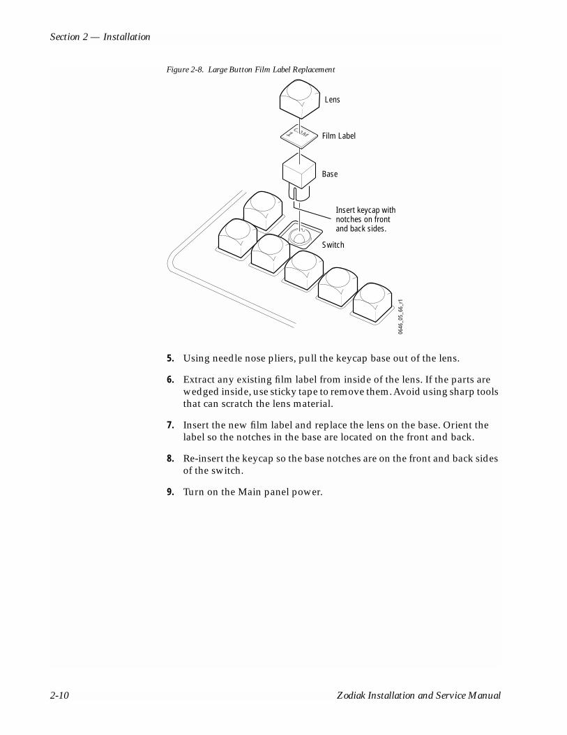
Section 2 — Installation
Figure 2-8. Large Button Film Label Replacement
5. Using needle nose pliers, pull the keycap base out of the lens.
6. Extract any existing film label from inside of the lens. If the parts are wedged inside, use sticky tape to remove them. Avoid using sharp tools that can scratch the lens material.
7. Insert the new film label and replace the lens on the base. Orient the label so the notches in the base are located on the front and back.
8. Re-insert the keycap so the base notches are on the front and back sides of the switch.
9. Turn on the Main panel power.
Lens
Switch
Insert keycap withnotches on frontand back sides.
0646
_05_
66_r
1
Base
Film LabelCAM1
2-10 Zodiak Installation and Service Manual

Main Panel Options
Remote Aux PanelsRemote Aux panels control Zodiak aux buses from remote locations. Three 24-Crosspoint and two 32-Crosspoint Remote Aux panel configurations are available for Zodiak systems. Refer to Table 2-3 and the following sections for panel-specific information.
Remote aux panels may be purchased with the Zodiak system or added at a later time. For more information on Zodiak options, refer to the Zodiak Data Sheet or Grass Valley Group Full Line Product Catalog. Online docu-mentation is available on the Grass Valley Group web site. The URL for the Grass Valley Group web site is found on the copyright page at the front of this manual.
Note Remote Aux panels used with Model 2200, 3000, and 4000 systems can be upgraded to 24-Crosspoint functionality for use in a Zodiak environment. See the Kalypso Model 4000 Remote Aux Panel Upgrade Instruction Manual for details. Online documentation is available on the Grass Valley Group web site. The URL for the Grass Valley Group website is found on the copyright page at the front of this manual.
24-Crosspoint Remote Aux PanelsThese panels are designed to select 48 external sources (24 unshifted and 24 shifted). Thirty-two 24-Crosspoint Remote Aux panels can be daisy-chained on a single serial control port on the Zodiak Video Processor frame. Three panel configurations are available, identified by the number of rack units (RUs) each occupies in a standard 19 in. (483 mm) equipment rack (see Figure 2-9 through Figure 2-11). The 1 and 2 RU panels (KAL-24AUX1 and KAL-24AUX2) are dedicated to a single bus. The 3 RU panel (KAL-24AUX3) panel has 18 bus delegate buttons. All three panels have the same connectors and DIP switches as that depicted for the KAL-24AUX1 in Figure 2-12 on page 12.
Table 2-3. Remote Aux Panel Summary
24-Crosspoint Aux Panel 32-Crosspoint Aux Panel
Connection Serial Port Daisy Chain Ethernet
Maximum Panels1
1 A maximum of 40 Remote Aux panels, in any combination, can be connected to a 2.5-M/E or 3-M/E.
32 40
External Sources Controlled 48 (24 unshifted, 24 shifted) 64 (32 unshifted, 32 shifted)
Available Configurations
KAL-24AUX1 (1 RU, single bus) KAL-32AUX1 (single bus)
KAL-24AUX2 (2 RU, single bus) KAL-32AUX2 (16 bus delegate buttons)
KAL-24AUX3 (3 RU, 18 bus delegate buttons) --
Zodiak Installation and Service Manual 2-11

Section 2 — Installation
Figure 2-9. KAL-24AUX1 (1 RU)
Figure 2-10. KAL-24AUX2 (2 RU)
Figure 2-11. KAL-24AUX3 (3 RU)
24-Crosspoint Remote Aux ConnectionsThe 24-Crosspoint Remote Aux rear panels have connectors for Communi-cations Bus, DC power, and Joystick Override (Figure 2-12).
Figure 2-12. KAL-24AUX1 (1 RU), Rear View
Note All KAL-24AUX rear panels have similar layouts and have the same connectors.
REMOTE AUX PANEL
1 2 3 4 5 6 7 8 9 1010 1111 1212 1313 1414 1515 1616 ONONAIRAIR1 2 3
PgmPgmPstPst
M/EM/E M/EM/E M/EM/E1717 1818 1919 2020 2121 2222 2323 2424 Shi f tShi f t
0619
_04_
64_r
1
REMOTE AUX PANELREMOTE AUX PANEL
10109876542 31
242423232222
1111
21212020191918181717
1616151513131212 1414
PstPstPgmPgm
3M/EM/E
2M/EM/E
1M/EM/EShiftShift
0619
_04_
67_r
1
REMOTE AUX PANELREMOTE AUX PANEL
10109876542 31
242423232222
1111
21212020191918181717
1616151513131212 1414
PstPstPgmPgm
3M/EM/E
2M/EM/E
1M/EM/EShiftShift
3A3AAuxAux
2A2AAuxAux
1A1AAuxAux
9A9AAuxAuxAuxAux
8A8AAuxAux7A7A6A6A
AuxAux5A5AAuxAux
4A4AAuxAux
AuxAux4B4B
AuxAux5B5B3B3B
AuxAux2B2BAuxAux
1B1BAuxAux AuxAux
9B9B7B7BAuxAux
8B8BAuxAuxAuxAux
6B6B
0619
_04_
69_r
1
-
+
COMMUNICATIONSBUS
SHIELD
DC POWER
JOYSTICK OVERRIDE
6432168421 8421
FORCE HIGH TALLY
MODETEST
ADDRESSPANEL
OFF
ON
0619
_04_
65_r
0
DC PowerTest Mode Panel Address and
Force High TallyJoystick OverrideCommunications Bus
2-12 Zodiak Installation and Service Manual

Main Panel Options
Joystick Override
A user fabricated cable, external switch, and a 9-pin D connector are required to implement camera joystick override. Use shielded cable and connect the shield to the metal connector shell when fabricating the joystick override cable. Refer to Figure 2-13 for connector wiring.
Figure 2-13. KAL-24AUX Joystick Override Connector Cable Wiring
Communications Bus
The communications bus cable connector shipped with each panel must be attached to the supplied cable or a user fabricated cable (refer to Figure 2-14). The supplied cable is 50 m (164 ft) long and has a pre-wired 9-pin D connector on one end. If fabricating a cable, use a shielded twisted pair cable such as Belden 8451 and refer to Table 2-4 for wiring connections.
Thirty-two 24-Crosspoint Remote Aux panels can be daisy-chained on a single serial control port on the Zodiak Video Processor frame, but the total length of cable in the panel daisy-chain cannot exceed 320 m (1000 ft). Allow enough cable to reach each control panel connector, plus about 1 m (approximately 3 ft) extra.
Momentary Contact Switches
0619
_04_
71_r
5
Pin 1
Pin 9Pin 6
Pin 5
Common
1
2
3
4
6
7
8
5
9
D-9 MaleJoystick Override
Connector(wiring side)
Zodiak Installation and Service Manual 2-13

Section 2 — Installation
Figure 2-14. KAL-24 AUX Communications Bus Connector Cable Wiring
Power Supply
The 24-Crosspoint Remote Aux panel power supply (Figure 2-15) should be securely fastened to a horizontal surface or attached to a support inside the equipment rack. Verify that the power supply cord reaches the 24-Crosspoint Remote Aux Control panel and the AC source.
Figure 2-15. KAL-24AUX Power Supply
Table 2-4. Cable Polarity
Panel Connector
D-Connector Pins
Factory Supplied Cable
+ (Plus) 3 and 7 Red
- (Minus) 2 and 8 Black
Shield 9 Shield
0619
_04_
66_r
0
To Pin 9 ofD Connector(SHIELD)
To Pins 2 and 8 ofD Connector (–)
To Pins 3 and 7 ofD Connector (+)
To Next Panel(If Any)
Side View Connector-endView
From Switcher orPrevious Panel
0619
_04_
63_r
0
2-14 Zodiak Installation and Service Manual

Main Panel Options
32-Crosspoint Remote Aux PanelsThese panels are designed to select 64 external sources (32 unshifted and 32 shifted). The number of 32-Crosspoint Remote Aux panels that can be network connected to the Zodiak Video Processor frame is 40. Two panel configurations are available, identified by the number of rack units (RUs) each occupies in the standard 19 in. (483 mm) equipment rack (see Figure 2-16 and Figure 2-17). Both panels have the same connector layout as that depicted for the KAL-32AUX1 in Figure 2-18.
The 1 RU panel (KAL-32AUX1) is dedicated to a single bus. The 2 RU panel (KAL-32AUX2) panel has 16 bus delegate buttons.
Figure 2-16. KAL-32AUX1 (1 RU)
Figure 2-17. KAL-32AUX2 (2 RU)
32-Crosspoint Remote Aux ConnectionsThe 32-Crosspoint Remote Aux rear panels have connectors for AC power, Camera Joystick Override and LAN (Figure 2-18).
Figure 2-18. KAL-32AUX1 (1 RU), Rear View
Note The rear panel layout is the same for both KAL-32AUX panels.
LAN
The 32-Crosspoint Remote Aux panels employ Ethernet network con-figuration. Refer to Ethernet Switches and Hubs on page 2-31 for informa-tion on system topography.
KALYPSO REMOTE AUX PANEL
1 2 3 4 5 6 7 8 9 10 11 12 13 14 15 16 M/E1
M/E2
M/E3
PgmPst
Hold
17 18 19 20 21 22 23 24 25 26 27 28 29 30 31 32 Un-Shift
Shift KeySplit
NearSide
FarSide
0619
_04_
58_r
3
R E M O T E A U X P A N E L
KALYPSO REMOTE AUX PANEL
1 2 3 4 5 6 7 8 9 10 11 12 13 14 15 16 M/E1
M/E2
M/E3
PgmPst
Hold
17 18 19 20 21 22 23 24 25 26 27 28 29 30 31 32 Un-Shift
Shift KeySplit
NearSide
FarSide
AUX1
AUX2
AUX3
AUX4
AUX5
AUX6
AUX7
AUX8
AUX9
AUX10
AUX11
AUX12
AUX13
AUX14
AUX15
AUX16
0619
_04_
60_r
3
R E M O T E A U X P A N E L
Display Area
RATED CURRENT: 0.35 ACAMERA JOYSTICK
OVERRIDEFREQUENCY: 47-440 Hz
RATED VOLTAGE RANGE: 85-260 VAC
LAN
0619
_04_
59_r
2
LANCamera Joystick OverrideAC Power
Zodiak Installation and Service Manual 2-15

Section 2 — Installation
Camera Joystick Override
A user fabricated cable, external switch, and a 15-pin D connector are required to implement camera joystick override. Use shielded cable and connect the shield to the metal connector shell when fabricating the joystick override cable. Refer to Figure 2-19 for connector wiring.
Figure 2-19. KAL-32AUX Joystick Override Connector Cable Wiring
AC Power
The 32-Crosspoint Remote Aux panels have internal power supplies which connect directly to facility AC power by supplied line cords.
Common
0619
_04_
62_r
3
1
2
3
4
6
7
8
5
9
10
11
12
13
15
14
Pin 1
Pin 15Pin 9
D-15 MaleJoystick Override
Connector(wiring side)
Pin 8
Momentary Contact Switches
2-16 Zodiak Installation and Service Manual

Menu Panel Installation
Menu Panel InstallationThe Menu panel includes a touch screen display, control processor, five knobs for adjusting parameter values, and a CD-ROM (Figure 2-20).
Figure 2-20. Menu Panel Dimensions
Ports located on the rear of the Menu panel (Figure 2-21) provide connec-tions to the Zodiak Main Panel, Video Processor frame, an external Zip drive, and other devices.
8096
_00_
13_r
0
14.75 in.375 mm
10.1 in.257 mm
5.80 in.147 mm
Allow clearancefor CD-ROM and
Fan Exhaust
1.0 in. / 25 mm
Fan
1.0 in. / 25 mm
CD-ROM
Zodiak Installation and Service Manual 2-17

Section 2 — Installation
Figure 2-21. Menu Panel Connections
CAUTION All Menu panel mounting holes are tapped 10-32. Do not penetrate the case more than 0.24 in. / 6.10 mm.
Recommended mounting locations for the Menu panel are to the left, right or behind the Main panel (refer to Figure 2-22 and Figure 2-23). These loca-tions provide for the most comfortable reach to the touch screen, soft knobs, and CD-ROM and also clears the area for better viewing of monitors beyond the Main panel.
Figure 2-22. Recommended Menu Panel Mounting Location
The adjustable console mounting bracket that ships with the Menu panel also allows it to be mounted from above, from below, or from the back, as shown in Figure 2-23. The right side of the panel requires clearance for the fan exhaust and access to the CD-ROM (see Figure 2-20). A four-hole
8096
_00_
14_r
2
2.5 in.64 mm
Left SideView
Panel Bottom
Rear of panel
Alternative four hole mounting pattern
Serial Ports
1.6 in.41 mm
4.3 in.109 mm
**
*
*
= Hole pair for standard mounting bracket*
USB Ports Ethernet Power
LAN DC INMOUSE KEYBOARDUSB 1
USB 2RESET
COM 3 CROSSOVER
COM 4
Link LED
0619
_00_
47r5
Menu Panel
Adjustable Console Bracket
ZODIAODIAKVIDEO PRODUCT ION SWITCHER
Console
Main Panel
2-18 Zodiak Installation and Service Manual
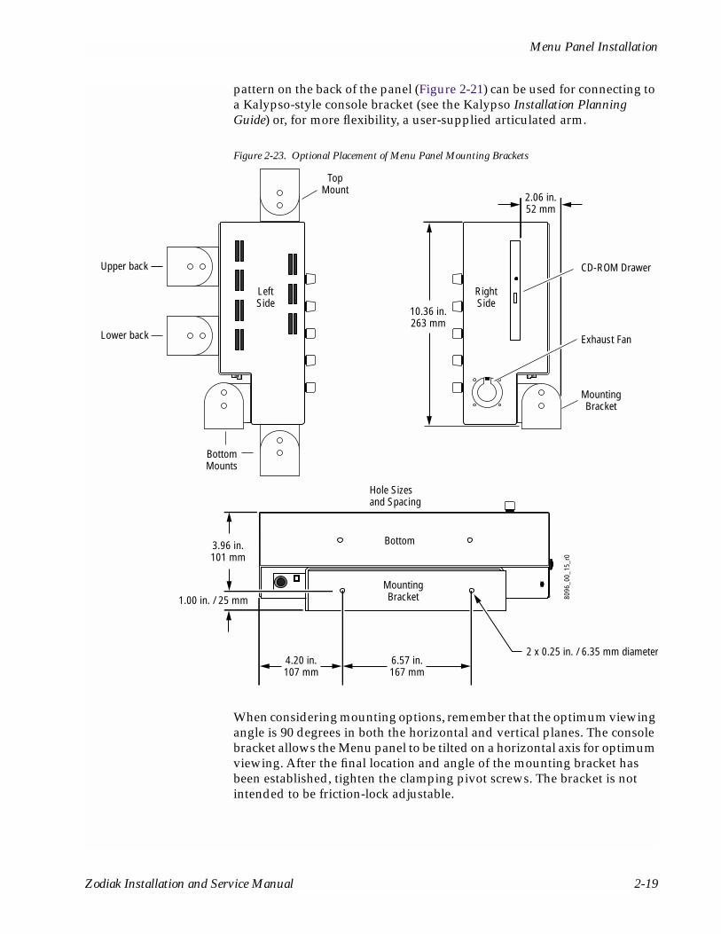
Menu Panel Installation
pattern on the back of the panel (Figure 2-21) can be used for connecting to a Kalypso-style console bracket (see the Kalypso Installation Planning Guide) or, for more flexibility, a user-supplied articulated arm.
Figure 2-23. Optional Placement of Menu Panel Mounting Brackets
When considering mounting options, remember that the optimum viewing angle is 90 degrees in both the horizontal and vertical planes. The console bracket allows the Menu panel to be tilted on a horizontal axis for optimum viewing. After the final location and angle of the mounting bracket has been established, tighten the clamping pivot screws. The bracket is not intended to be friction-lock adjustable.
2.06 in.52 mm
10.36 in.263 mm
BottomMounts
6.57 in.167 mm
2 x 0.25 in. / 6.35 mm diameter
Bottom
LeftSide
RightSide
MountingBracket
4.20 in.107 mm
3.96 in.101 mm
1.00 in. / 25 mm
Upper back
Lower back
CD-ROM Drawer
TopMount
MountingBracket
Hole Sizesand Spacing
8096
_00_
15_r
0
Exhaust Fan
Zodiak Installation and Service Manual 2-19

Section 2 — Installation
VentilationAir is drawn into the Menu panel through slots along the top and left side of the panel. Air is expelled out of the Menu panel by a fan located on the right side of the panel (see Figure 2-20). When mounting the panel, be sure to leave either the top or left side slots unobstructed for proper air intake. The right side of the panel requires clearance for the fan exhaust and access to the CD-ROM.
Cabling and PinoutsFigure 2-28 on page 2-28 illustrates the cabling between the Menu panel and other system components. Table 2-5 provides pinouts for the Menu panel console ports.
Table 2-5. Menu Panel Console Ports
Console PortsRS-232 Pin Menu Proc.
COM 3Menu Proc.
COM 4
1 DSD DSD
2 RXD RXD
3 TXD TXD
4 DTR DTR
5 Chassis GND Chassis GND
6 DSR DSR
7 RTS RTS
8 CTS CTS
9 Menu Reset1
1 Reset is active low.
RI (Ring Indicator)
Pin 1
Pin 9
Pin 6
D-9 Male
Pin 5
2-20 Zodiak Installation and Service Manual

Video Processor Frame Installation
Video Processor Frame InstallationThe Zodiak Video Processor frame is a 7 rack unit chassis which mounts in a standard 483 mm (19 in.) rack (Figure 2-24). It has a built-in cooling system consisting of a fan/plenum mounted in the right section of the frame, and an air filter in the left section. Cooling air is drawn in at the left side of the frame, through the filter and modules, then expelled at the right of the fan/plenum unit.
Figure 2-24. Video Processor Frame Rack Installation
17 in.432 mm
12.25 in.311 mm
22.13 in.562 mm
AirIntake
19 in.483 mm
8096
_00_
12_r
2
Air Exhaust
Frame supportplate mounts(both sides)
Rear rack plate
Zodiak Installation and Service Manual 2-21
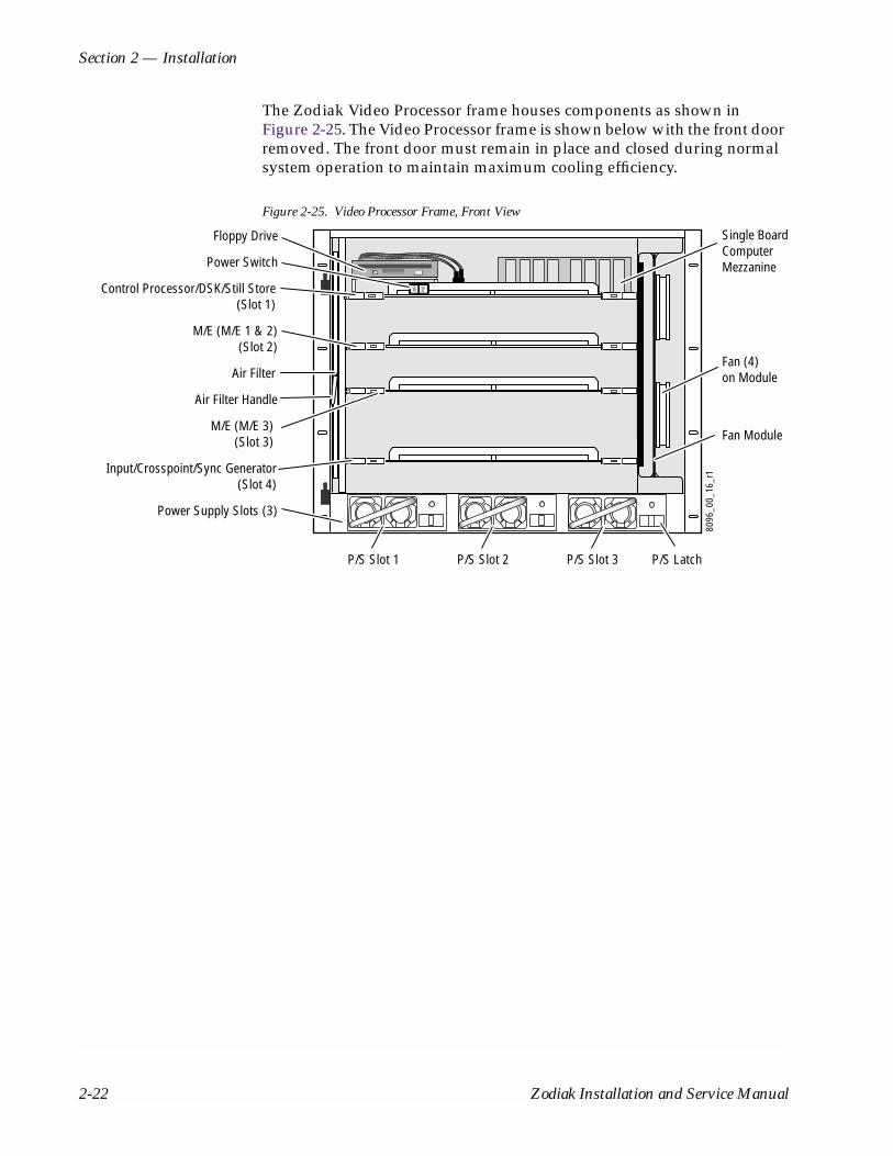
Section 2 — Installation
The Zodiak Video Processor frame houses components as shown in Figure 2-25. The Video Processor frame is shown below with the front door removed. The front door must remain in place and closed during normal system operation to maintain maximum cooling efficiency.
Figure 2-25. Video Processor Frame, Front View
8096
_00_
16_r
1
ON
OFFControl Processor/DSK/Still Store(Slot 1)
M/E (M/E 1 & 2)(Slot 2)
Fan Module
Floppy Drive
M/E (M/E 3)(Slot 3)
Input/Crosspoint/Sync Generator(Slot 4)
Power Supply Slots (3)
Air Filter
Air Filter Handle
Fan (4)on Module
P/S Slot 2P/S Slot 1 P/S Slot 3 P/S Latch
Single BoardComputerMezzaninePower Switch
2-22 Zodiak Installation and Service Manual
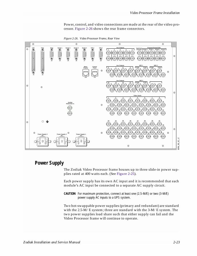
Video Processor Frame Installation
Power, control, and video connections are made at the rear of the video pro-cessor. Figure 2-26 shows the rear frame connectors.
Figure 2-26. Video Processor Frame, Rear View
Power SupplyThe Zodiak Video Processor frame houses up to three slide-in power sup-plies rated at 400 watts each. (See Figure 2-25).
Each power supply has its own AC input and it is recommended that each module’s AC input be connected to a separate AC supply circuit.
CAUTION For maximum protection, connect at least one (2.5-M/E) or two (3-M/E) power supply AC inputs to a UPS system.
Two hot-swappable power supplies (primary and redundant) are standard with the 2.5-M/E system; three are standard with the 3-M/E system. The two power supplies load share such that either supply can fail and the Video Processor frame will continue to operate.
Aux OutputsAux Outputs
Aux OutputsAux Outputs
PGMPGM PVWPVW
M/E 2M/E 2M/E 1M/E 1
Power Supply 1Power Supply 1ACAC
Power Supply 2Power Supply 2ACAC
Power Supply 3Power Supply 3ACAC
AnalogAnalogReference InReference In
646463636262616060595958585757
5656555454535252515150504949
484847474646454444434342424141
40403939383837373636353534343333
32323131303029292828272726262525
242423232222212120201918181717
1616151413131212111110109
87654321
Video InputsVideo Inputs
M/E 3M/E 3
PVWPVWPGMPGMPVWPVWPGMPGM
1313121211111010
9876
PrograProgram/PresePreset/DSKDSKAux OutputsAux Outputs
ControlControlPanelPanel
MenuMenuDisplayDisplay
J11J11J10J10
J9J9J8J8J7J7J6J6J5J5J4J4J3J3
J2J2J1J1
PVW BPVW BPGM BPGM BPVW APVW APGM APGM ASwitchedSwitchedPreviewPreview54321
CPL2CPL2CPL1CPL1Serial 4Serial 4Serial 3Serial 3Serial 2Serial 2Serial 1Serial 1DiagDiagTallyTallyGPIGPI
8096
_00_
02_r
2
Zodiak Installation and Service Manual 2-23
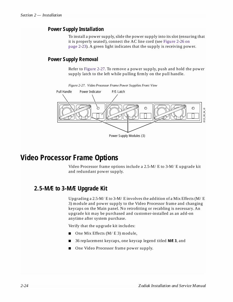
Section 2 — Installation
Power Supply InstallationTo install a power supply, slide the power supply into its slot (ensuring that it is properly seated), connect the AC line cord (see Figure 2-26 on page 2-23). A green light indicates that the supply is receiving power.
Power Supply Removal
Refer to Figure 2-27. To remove a power supply, push and hold the power supply latch to the left while pulling firmly on the pull handle.
Figure 2-27. Video Processor Frame Power Supplies Front View
Video Processor Frame OptionsVideo Processor frame options include a 2.5-M/E to 3-M/E upgrade kit and redundant power supply.
2.5-M/E to 3-M/E Upgrade KitUpgrading a 2.5-M/E to 3-M/E involves the addition of a Mix Effects (M/E 3) module and power supply to the Video Processor frame and changing keycaps on the Main panel. No retrofitting or recabling is necessary. An upgrade kit may be purchased and customer-installed as an add-on anytime after system purchase.
Verify that the upgrade kit includes:
■ One Mix Effects (M/E 3) module,
■ 36 replacement keycaps, one keycap legend titled M/E 3, and
■ One Video Processor frame power supply.
8125
_00_
04_r
0
Power Supply Modules (3)
P/S LatchPull Handle Power Indicator
2-24 Zodiak Installation and Service Manual
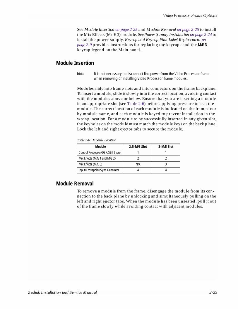
Video Processor Frame Options
See Module Insertion on page 2-25 and Module Removal on page 2-25 to install the Mix Effects (M/E 3) module. SeePower Supply Installation on page 2-24 to install the power supply. Keycap and Keycap Film Label Replacement on page 2-9 provides instructions for replacing the keycaps and the M/E 3 keycap legend on the Main panel.
Module Insertion
Note It is not necessary to disconnect line power from the Video Processor frame when removing or installing Video Processor frame modules.
Modules slide into frame slots and into connectors on the frame backplane. To insert a module, slide it slowly into the correct location, avoiding contact with the modules above or below. Ensure that you are inserting a module in an appropriate slot (see Table 2-6) before applying pressure to seat the module. The correct location of each module is indicated on the frame door by module name, and each module is keyed to prevent installation in the wrong location. For a module to be successfully inserted in any given slot, the keyholes on the module must match the module keys on the back plane. Lock the left and right ejector tabs to secure the module.
Module RemovalTo remove a module from the frame, disengage the module from its con-nection to the back plane by unlocking and simultaneously pulling on the left and right ejector tabs. When the module has been unseated, pull it out of the frame slowly while avoiding contact with adjacent modules.
Table 2-6. Module Location
Module 2.5-M/E Slot 3-M/E Slot
Control Processor/DSK/Still Store 1 1
Mix Effects (M/E 1 and M/E 2) 2 2
Mix Effects (M/E 3) N/A 3
Input/Crosspoint/Sync Generator 4 4
Zodiak Installation and Service Manual 2-25
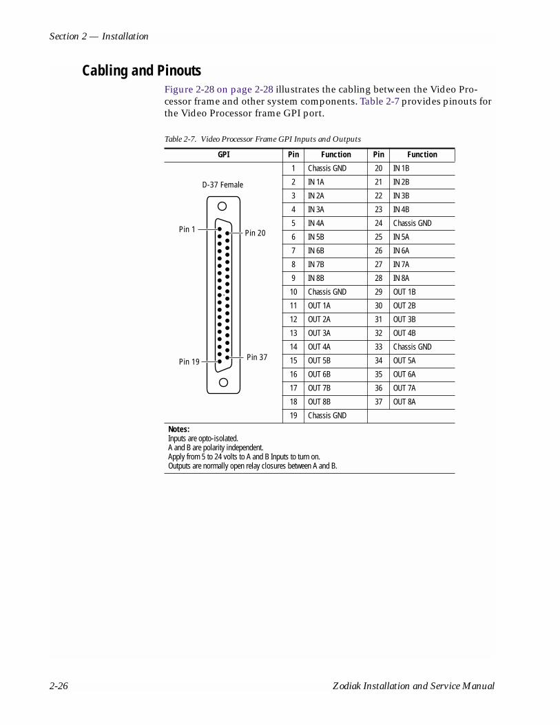
Section 2 — Installation
Cabling and PinoutsFigure 2-28 on page 2-28 illustrates the cabling between the Video Pro-cessor frame and other system components. Table 2-7 provides pinouts for the Video Processor frame GPI port.
Table 2-7. Video Processor Frame GPI Inputs and Outputs
GPI Pin Function Pin Function
1 Chassis GND 20 IN 1B
2 IN 1A 21 IN 2B
3 IN 2A 22 IN 3B
4 IN 3A 23 IN 4B
5 IN 4A 24 Chassis GND
6 IN 5B 25 IN 5A
7 IN 6B 26 IN 6A
8 IN 7B 27 IN 7A
9 IN 8B 28 IN 8A
10 Chassis GND 29 OUT 1B
11 OUT 1A 30 OUT 2B
12 OUT 2A 31 OUT 3B
13 OUT 3A 32 OUT 4B
14 OUT 4A 33 Chassis GND
15 OUT 5B 34 OUT 5A
16 OUT 6B 35 OUT 6A
17 OUT 7B 36 OUT 7A
18 OUT 8B 37 OUT 8A
19 Chassis GND
Notes:Inputs are opto-isolated.A and B are polarity independent.Apply from 5 to 24 volts to A and B Inputs to turn on.Outputs are normally open relay closures between A and B.
Pin 1
Pin 19
Pin 20
Pin 37
D-37 Female
2-26 Zodiak Installation and Service Manual

Video Processor Frame Options
Table 8. Video Processor Frame Serial Ports
RS-422 Ports Pin Serial/CPL PortsJ4 -J9
1 Chassis GND
2 TX-
3 RX+
4 Chassis GND
5 Reserved
6 Chassis GND
7 TX+
8 RX-
9 Chassis GND
Notes:Ports J4 – J9: The data directions specified on pins 2&3 and 7&8 as RX and TX may be reversed in software configuration.
Table 9. Video Processor Frame Tally Port
Tally Port Pin Function Pin Function
1 Tally 1 20 Tally 20
2 Tally 2 21 Tally 21
3 Tally 3 22 Tally 22
4 Tally 4 23 Tally 23
5 Tally 5 24 Tally 24
6 Tally 6 25 Tally 25
7 Tally 7 26 Tally 26
8 Tally 8 27 Tally 27
9 Tally 9 28 Tally 28
10 Tally 10 29 Tally 29
11 Tally 11 30 Tally 30
12 Tally 12 31 Tally 31
13 Tally 13 32 Tally 32
14 Tally 14 33 Reserved
15 Tally 15 34 Reserved
16 Tally 16 35 Reserved
17 Tally 17 36 Tally Common1
18 Tally 18 37 Chassis GND
19 Tally 19 1 Outputs are relay closures between the respective tally pin and Tally Common (pin 36).
Pin 5
Pin 6
Pin 9
D-9 Female
Pin 1
Pin 1
Pin 19
Pin 20
Pin 37
D-37 Female
Zodiak Installation and Service Manual 2-27
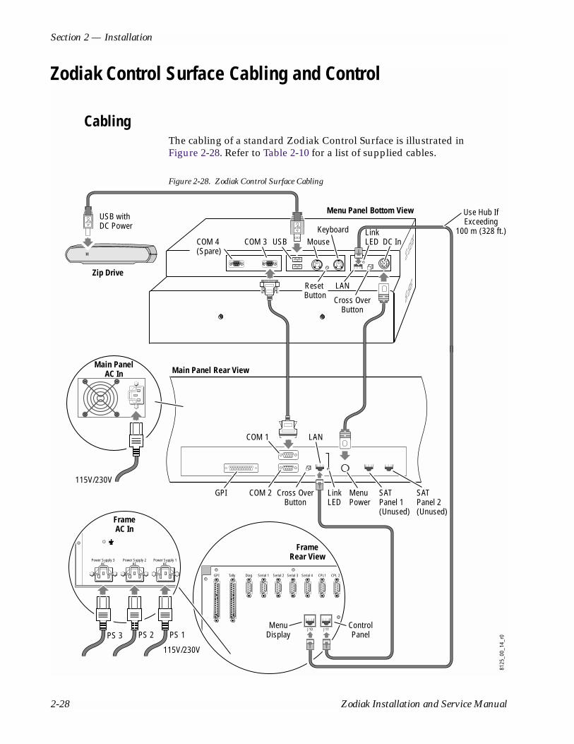
Section 2 — Installation
Zodiak Control Surface Cabling and Control
CablingThe cabling of a standard Zodiak Control Surface is illustrated in Figure 2-28. Refer to Table 2-10 for a list of supplied cables.
Figure 2-28. Zodiak Control Surface Cabling
115V/230V
Main PanelAC In
COM 4(Spare)
8125
_00_
14_r
0
Menu Panel Bottom View
Main Panel Rear View
Zip Drive
FrameRear View
FrameAC In
GPI LinkLED
SAT Panel 1(Unused)
SAT Panel 2(Unused)
COM 2 Cross OverButton
COM 1
COM 3 USB Mouse DC In
MenuPower
USB withDC Power
115V/230V
PS 1PS 2PS 3
Keyboard
Reset Button
LAN
LAN
Cross OverButton
GPI Tally Diag Serial 1
Power Supply 1AC
Power Supply 2AC
Power Supply 3AC
Serial 2 Serial 3 Serial 4 CPL1 CPL 2
LinkLED
Use Hub IfExceeding
100 m (328 ft.)
MenuDisplay
ControlPanel
J10 J11
2-28 Zodiak Installation and Service Manual

Zodiak Control Surface Cabling and Control
ControlA simple Zodiak system consisting of a Main panel, Menu panel, and Video Processor frame uses point-to-point connections and does not require an Ethernet Local Area Network (LAN) (see Figure 2-28).
The Zodiak system uses Ethernet, serial, parallel, and USB. Tally and GPI control are available (see Figure 2-29).
Figure 2-29. Simple Zodiak System Control
Table 2-10. Supplied Cables
Cable Description Quantity
AC Power Supply Cable — Main Panel AC line cord kit 2
AC Power Supply Cable — 3-M/E Frame AC line cord kit 31
1 Two supplied cables for a 2.5-M/E frame.
Main Panel to Menu Panel DC Power 8-pin DIN, male-to-male, 3 m (10 ft) 1
Menu Panel to ZIP 250 USB USB AB cable, 1.83 m (6 ft) 1
Menu Panel to Main Panel 9-pin D, male-to-female serial, 3 m (10 ft) 1
Panel LAN, Menu LAN Category 5, 100 Base-T, 30 m (100 ft) 2
Menu LAN
USB
Optional Keyboard
Optional Mouse
Menu Panel
Zip Drive
OptionalFuture SatellitePanels (1-2)
NOTE: Main Panel, Menu LAN, Panel LAN 10Base-T or 100Base-T Ethernnet
Main Panel
Point to Point SerialRS-422/Serial Async
8096
_00_
19_r
1
Main Control Surface
FloppyDriveReal Time Processor
System Processor
Button Knob Control (Serial)
Touch Screen Control (Serial)
8 GPI In8 GPI Out4 Serial
Tally (Relay)
2 Synchronous Serial
Video Processor Frame
Cont
rol
Syst
em
HardDrive
FloppyDrive
CD-ROM
Panel LAN
Control LineControl Surface Boundary
Serial
Zodiak Installation and Service Manual 2-29
Section 2 — Installation
Cable Polarity and Cross Over ButtonWhenever making point-to-point connections between the Control panel(s) and the Video Processor frame, the Transmit (TX) and Receive (RX) pairs in the cable need to be swapped. This is normally achieved with a special peer-to-peer (crossover) LAN cable or an Uplink port on the switch or hub. The Zodiak Main panel and Menu panel each have Cross Over buttons and LAN Link LEDs (see Figure 2-7 and Figure 2-21). If no commu-nication can be established (the LAN Link LED is off), a possible cause may be incorrect cable polarity. Polarity is reversed by pressing the Cross Over button on the Main and Menu panels. When communication is established, the LAN Link LED illuminates.
LAN RequirementsA simple Zodiak system uses point-to-point connections and does not require an Ethernet Local Area Network (LAN) (see Figure 2-30).
A Zodiak system requires a LAN when components in addition to a Main panel, Menu panel, and Video Processor frame are connected or when external network access to the Still Store file system is desired. An appro-priately sized Ethernet switch will be required (see Figure 2-31).
CAUTION Ethernet hubs are not acceptable for the main Zodiak Ethernet interconnect but are necessary to exceed maximum cable runs. Use of a hub instead of a switch may cause sluggish responses to panel button presses and erratic lever arm motion. An existing facility Ethernet switch (not hub) can support Zodiak if an adequate number of ports are available. Keep your facility network and technical network separate in order to avoid network traffic neg-atively affecting Zodiak system operation.
Refer to Table 2-11 for Ethernet specifications.
Note All Ethernet components must be supplied by the customer.
Table 2-11. Ethernet Specifications
Cables1
1 The system will work at 10Base-T with reduced performance. 100Base-T components are highly recommended.
Type 10Base-T and 100Base-T compatible. Category 5 cable, 8 conductor twisted pair.
Connectors RJ-45 male connector at each end of cable.
Length2
2 Use a hub when necessary to exceed maximum cable runs.
10Base-T: 300 m (984 ft) maximum. 100Base-T: 100 m (328 ft) maximum.
Switch3
3 Optional
Speed Dual: 10 and 100 Mb
Ports RJ-45 auto-negotiating 10/100 Mb; number of ports required is dependent upon system size.
Unmanaged Recommended. Configuration not required, but do not provide remote monitoring capability.
Managed May be used. Require configuration, but offer remote monitoring capability.
2-30 Zodiak Installation and Service Manual

Zodiak Control Surface Cabling and Control
Ethernet Switches and HubsZodiak optional components rely primarily on Ethernet switches for LAN interconnects (see Figure 2-31). 32-Crosspoint Remote Aux panels may be connected directly to the Zodiak switch, or through an Ethernet hub. A hub is required only if there is a need to exceed 100 m (328 ft) between a panel and Video Processor frame. If a hub is used, connect the hub to the switch via the Uplink port, or through a peer-to-peer crossover cable. Reserve a port on Zodiak’s Ethernet switch if you will be utilizing a hub or switch.
Note The number and type of components in your Zodiak system determines the size of the switch (number of ports) required. Refer to the following examples of system topography and the accompanying worksheet to determine the number of ports required for your system.
Figure 2-30. Example Topography Not Requiring an Ethernet Switch
8098
_00_
20_r
0
Video Processor Frame
Panel LAN
Menu Panel
Menu System Processor
Real Time Processor
Main Panel
Menu LAN
Zodiak Installation and Service Manual 2-31
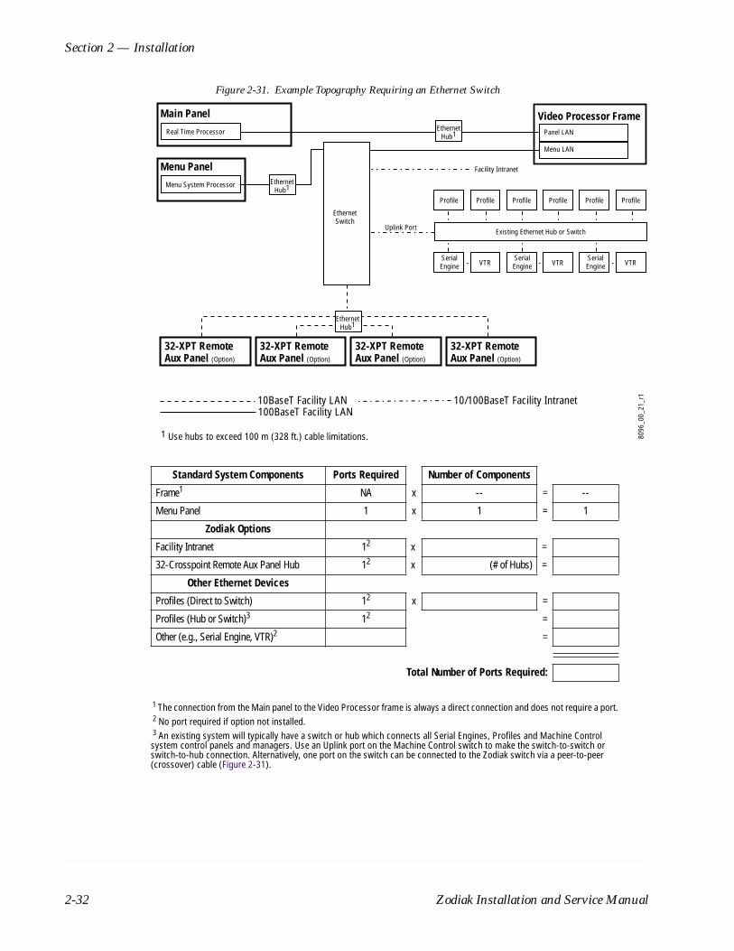
Section 2 — Installation
Figure 2-31. Example Topography Requiring an Ethernet Switch
Standard System Components Ports Required Number of Components
Frame1
1 The connection from the Main panel to the Video Processor frame is always a direct connection and does not require a port.
NA x -- = --
Menu Panel 1 x 1 = 1
Zodiak Options
Facility Intranet 12
2 No port required if option not installed.
x =
32-Crosspoint Remote Aux Panel Hub 12 x (# of Hubs) =
Other Ethernet Devices
Profiles (Direct to Switch) 12 x =
Profiles (Hub or Switch)3
3 An existing system will typically have a switch or hub which connects all Serial Engines, Profiles and Machine Control system control panels and managers. Use an Uplink port on the Machine Control switch to make the switch-to-switch or switch-to-hub connection. Alternatively, one port on the switch can be connected to the Zodiak switch via a peer-to-peer (crossover) cable (Figure 2-31).
12 =
Other (e.g., Serial Engine, VTR)2 =
Total Number of Ports Required:
Facility Intranet
8096
_00_
21_r
1
Uplink Port
SerialEngine VTR
SerialEngine VTR
SerialEngine VTR
Profile Profile Profile Profile Profile Profile
Existing Ethernet Hub or Switch
Real Time Processor
Main Panel
10BaseT Facility LAN100BaseT Facility LAN
10/100BaseT Facility Intranet
32-XPT RemoteAux Panel (Option)
32-XPT RemoteAux Panel (Option)
32-XPT RemoteAux Panel (Option)
32-XPT RemoteAux Panel (Option)
EthernetHub1
Video Processor FramePanel LAN
1 Use hubs to exceed 100 m (328 ft.) cable limitations.
Menu Panel
Menu System Processor
EthernetSwitch
EthernetHub1
EthernetHub1
Menu LAN
2-32 Zodiak Installation and Service Manual

Zodiak Control Surface Cabling and Control
VideoDifferent video and control wiring configurations may be used to meet individual facility requirements. All Zodiak system video inputs and AUX outputs are configurable. For cabling configuration flexibility, each input can be mapped to any Zodiak panel source select button, and any Zodiak system video signal can be mapped to any AUX output connectors. Program and Preview bus outputs for each M/E have dedicated output connectors as well.
Refer to Figure 1-6 on page 1-10 for an example of a basic Zodiak system configuration.
InputsPhysical inputs are the actual BNC connectors that feed a signal into Zodiak. These non-looping inputs on the back of the Video Processor Frame are numbered 1 through 64. Each receives a 270 MHz serial digital video signal. All video inputs are software configurable, and each input can be mapped to any Zodiak panel source select button. For correct operation of the autotimer circuits, inputs should arrive at the switcher ± 10 microsec-onds of the reference input.
OutputsThe Zodiak frame provides dedicated program and preview video output connectors for each M/E. Each 270 MHz serial output signal is available on two BNC connectors. Any Zodiak video source can be routed to any Aux bus output (1 through 13).
Reference InputThe looping reference input accepts analog 525 or 625 composite video. Burst is not required, but typically facility reference color black is used. The timing of all switcher inputs and outputs are referenced to this signal.
Zodiak Installation and Service Manual 2-33

Section 2 — Installation
2-34 Zodiak Installation and Service Manual
Section 3Configuration
IntroductionThis section provides system configuration information for the Zodiak Video Production Switcher. Refer to the latest Zodiak Release Notes for information specific to your current software version.
Basic Configuration Steps1. Power up the system.
2. Configure Zodiak in a network.
3. Set IP addresses (if required).
4. Define and save Engineering Setups.
5. Define and save Suite Preferences.
6. Define and save User Preferences.
Power UpThe Zodiak Video Processor frame and Main panel must be powered up for full system operation. The Menu panel receives its primary power from the Main panel.
1. Set the power switch on the Video Processor Frame to On (Figure 3-1 on page 3-2).
2. Set the power switch(es) in the Main Panel tub enclosure to On (Figure 3-2 on page 3-2).
Zodiak Installation and Service Manual 3-1

Section 3 — Configuration
Figure 3-1. Video Processor Frame Front, Power Switch (Door Open)
CAUTION The front door of the Zodiak Video Processor must remain closed during normal system operation for proper cooling airflow.
Figure 3-2. Main Panel, Lid Open
8125
_00_
02_r
0
ON
OFF
Power Switch
Main Power SupplyOn/Off Switch
Redundant Power SupplyOn/Off Switch
8125
_00_
03r0
3-2 Zodiak Installation and Service Manual

Power Up
Power and Initialization IndicationsPower to the system is indicated by operation of the fans in the Main panel, Video Processor frame, and green lights on the Video Processor frame power supplies.
When the Zodiak system powers up or is reset, the first portions of the system activated are the PGM PST buses, transition, and keying controls. This permits rapid on-air recovery of basic system operations. Sources can be cut, mixed, and wiped, and keys placed taken on and off air while the rest of the system initializes. The Menu panel system is the last item to ini-tialize after system power up. The first screen displays the Grass Valley Group logo and the menu software version, and then the entire system is fully operational.
Systems display their software versions on the Versions menu. Press the Status/Diags button in the Home menu, then touch the Versions data pad (refer to Figure 3-3).
Note If a Frame Not Connected or similar message appears on a panel, communi-cation with the Video Processor frame has been interrupted. The frame may need to be powered up or reset, the IP Address may be incorrect, or some other LAN problem may exist that will need to be corrected.
Figure 3-3. Software Versions
Zodiak Installation and Service Manual 3-3

Section 3 — Configuration
Network ConfigurationsThe physical communication link between Zodiak components and other devices is done through Ethernet connections. Two LANs are designed into the Zodiak system for optimal operation of the switcher, the Panel and Menu (also called the Facility) LANs. This is done to isolate the Main panel network from the Menu (Facility) LAN to avoid loss of communication between the Main panel and the frame should the Facility LAN fail. Two fundamental networking configurations are presented here; one for a stand alone network with only Zodiak components, and another for connecting to an existing Ethernet network.
Standalone Configuration
The Zodiak system default configuration includes IP addresses designed for standalone plug-and-play installation (Table 3-1 on page 3-6). This default configuration allows Zodiak components to communicate with one another with no IP address configuration necessary. However, this config-uration does not allow communication with other devices in your facility if required.
A standalone Zodiak network with default IP addresses is illustrated in Figure 3-4. In this configuration, both the Main panel and the Menu panel are connected directly to the Video Processor frame, each on a separate LAN. The Host IP addresses given are the default IP addresses set at the factory. The Gateway addresses are assigned dynamically based upon the current Frame and Panel IP addresses to allow forwarding information between the Main panel and the Menu panel.
The Gateway IP addresses permit a host (Main panel or Menu panel) to forward packet information to another host residing on a physically dif-ferent network. In this case, the two networks, Panel LAN and Menu LAN, use the Video Processor frame as the gateway for communication between the two panels. Note that the Gateway addresses for each panel correspond to the Host IP addresses of the Video Processor frame, allowing the frame to act as the gateway.
If you are using this standalone configuration, there is no IP address con-figuration necessary. You may proceed to Software Installation on page 3-17.
Figure 3-4. Standalone Zodiak Network
PanelLAN
MenuLAN
Main Panel Menu PanelVideo Processor Frame
Host IP: 192.168.55.8Gateway IP: 192.168.55.18
Host IP: 192.168.54.8Gateway IP: 192.168.54.18
Host IP: 192.168.55.18 Host IP: 192.168.54.18
8125
_00_
09r0
3-4 Zodiak Installation and Service Manual

Power Up
Connecting to an Existing NetworkConnecting the Zodiak system to your existing facility Ethernet backbone, or adding additional Zodiak components — such as Remote Aux panels — requires additional network configuration. The approach presented here involves using an additional customer-supplied Ethernet switch and Gateway device to connect the Zodiak network to an existing LAN.
The network configuration shown in Figure 3-5 allows the Zodiak system to be connected to an existing Facility LAN. An Ethernet switch is added between the Video Processor frame and the Menu panel. This switch is then connected to a full-featured Gateway or Router device connected to the Menu LAN. This allows the Zodiak system to talk via the Gateway device to the rest of the facility, represented as the IP Cloud.
The Host IP address of the Gateway device must be configured from an external source, usually by a Network Administrator. When a different IP address is required for the Menu LAN, the IP addresses for the Menu panel and the Video Processor frame in the Menu LAN can be changed as described in the next section. In most cases the Panel LAN IP addresses will always remain the same, but instructions are also given for this device.
This configuration requires that both the frame and Menu panel know the Gateway IP address of the external device, in this case — 192.168.54.1. This allows information packets not destined for the Panel or Menu LAN to be forwarded for further routing.
Once the Zodiak system has been connected to an external gateway that has been properly configured, it will be possible to FTP into the frame from a personal computer with a route to the external gateway. Another LAN may also be accessed from the Menu panel as well.
Figure 3-5. Zodiak Connection to an Existing Network
PanelLAN
MenuLAN
Main Panel Video Processor Frame
Host IP: 192.168.55.8Gateway IP: 192.168.55.18
Host IP: 192.168.54.8Default IP: 192.168.54.1
Host IP: 192.168.54.18Gateway IP: 192.168.54.1Host IP: 192.168.55.18
Host IP: 192.168.54.1
8125
_00_
10r0
Menu Panel
Switch
Gateway
IP Cloud
Zodiak Installation and Service Manual 3-5

Section 3 — Configuration
IP AddressesThe Zodiak system is shipped from the factory set with the default IP addresses given in Table 3-1. An IP address has two components: the network prefix and the host number. The Subnet mask defines the dividing line between the two. The first three octets of the Subnet Mask provide the network address; the fourth is the node address. Nodes with the same network address can communicate directly with each other, while nodes with different network addresses normally do not communicate directly.
As explained earlier, the Zodiak system has two Ethernet LANs for panel and frame communications (Menu LAN and Panel LAN). The Menu LAN (also called the Facility LAN) is used for all system communications. The Panel LAN is used to communicate between the Main panel and the Video Processor frame. The Main panel communicates with the Menu panel via a gateway through the frame.
The default IP addresses shipped from the factory have been chosen to make Zodiak configuration easy. Numbers were chosen to work with other Grass Valley Group devices in a default standalone network configuration.
Note All Subnet mask values are the same for all nodes and are set to 255.255.255.0.
If the default network configuration does not fit your existing Ethernet con-figuration, they may be changed as explained in the next section to conform to the in-house standards for your facility. Make sure all nodes have unique node addresses and are placed on the appropriate network. If other devices are present on the network, ensure that each device has a unique IP address. If more than one Zodiak system resides on the same network, the IP address of each additional Zodiak system device must be changed before it is connected to the network.
Table 3-1. Default IP Addresses
Device IP Address
Video Processor frame Host IP: 192.168.54.18 (Menu LAN)
Host IP: 192.168.55.18 (Panel LAN)
Gateway IP: 192.168.54.1 (External Gateway)
Main panel Host IP: 192.168.55.8 (Panel LAN)
Gateway IP: 192.168.55.18 (To Menu Panel)
Frame IP: 192.168.55.18 (Panel LAN)
Menu IP: 192.168.54.8
Menu panel Host IP: 192.168.54.8 (Menu LAN)
Frame IP: 192.168.54.18 (Menu LAN)
Default Gateway: 192.168.54.1 (External Gateway)
Panel IP: 192.168.55.8
3-6 Zodiak Installation and Service Manual

Power Up
See your network System Administrator before connecting the Zodiak system to an existing network or making any IP address changes. The IP addresses (including any Subnet mask) of all the Zodiak devices on the network must be known before any changes are made.
Fundamental IP Routing Concept
In summary, there are two devices situated on either side of the Video Frame, the Main panel (also called the Real Time or RT panel), and the Menu panel. If you change the Host IP address of one end node, then you must update the other end node's IP address table so that it knows how to reach the node you just changed. For example, if you change the Menu Panel's Host IP address from 192.168.54.8 to 192.168.54.10, the you must change the Main Panel's IP address to the Menu Panel to 192.168.54.10. You do not change the Main Panel's host IP address in this scenario.
If, however, you change the Frame's IP addresses, then you must change both the gateway addresses and the target IP addresses to the Frame for the Main Panel and Menu Panel. The reason you perform this step is the fol-lowing:
■ Each end node knows how to talk to the Frame (these are the target IP addresses to the Frame), and
■ Both end nodes know how to send packets to each other by using the Frame as a gateway or conduit through which the packets flow (these are gateway addresses).
Changing IP Addresses
The Menu panel, Main panel and Video Processor frame each have a dif-ferent method for changing their IP addresses. Correct IP addressing is essential to proper communication between Zodiak devices. Change IP addresses with care and read the entire procedure and any notes or cau-tions before proceeding.
The IP addresses for each Zodiak device must be changed directly from each device through the appropriate interface. Note that in the process of setting the Host IP address for a particular device, the IP addresses of the other Zodiak devices on the network will also be displayed and can be edited. Editing these values does not change the other devices’ Host IP addresses. It informs the device you are currently changing what the target and gateway IP addresses are for the other Zodiak devices on the network. Each Zodiak device must know the target and gateway IP addresses on the network to communicate properly.
After changing any of the IP addresses, each device, including the Menu panel Windows 2000 application, should be restarted to enable the new values and refresh internal routing tables which are updated dynamically when devices are restarted.
Zodiak Installation and Service Manual 3-7
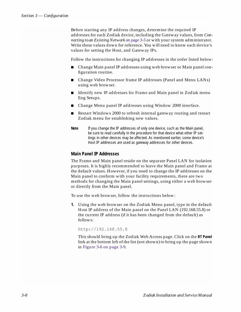
Section 3 — Configuration
Before starting any IP address changes, determine the required IP addresses for each Zodiak device, including the Gateway values, from Con-necting to an Existing Network on page 3-5 or with your system administrator. Write these values down for reference. You will need to know each device’s values for setting the Host, and Gateway IPs.
Follow the instructions for changing IP addresses in the order listed below:
■ Change Main panel IP addresses using web browser or Main panel con-figuration routine.
■ Change Video Processor frame IP addresses (Panel and Menu LANs) using web browser.
■ Identify new IP addresses for Frame and Main panel in Zodiak menu Eng Setups.
■ Change Menu panel IP addresses using Window 2000 interface.
■ Restart Windows 2000 to refresh internal gateway routing and restart Zodiak menu for establishing new values.
Note If you change the IP addresses of only one device, such as the Main panel, be sure to read carefully in the procedure for that device what other IP set-tings in other devices may be affected. As mentioned earlier, some device’s Host IP addresses are used as gateway addresses for other devices.
Main Panel IP AddressesThe Frame and Main panel reside on the separate Panel LAN for isolation purposes. It is highly recommended to leave the Main panel and Frame at the default values. However, if you need to change the IP addresses on the Main panel to conform with your facility requirements, there are two methods for changing the Main panel settings, using either a web browser or directly from the Main panel.
To use the web browser, follow the instructions below:
1. Using the web browser on the Zodiak Menu panel, type in the default Host IP address of the Main panel on the Panel LAN (192.168.55.8) or the current IP address (if it has been changed from the default) as follows:
http://192.168.55.8
This should bring up the Zodiak Web Access page. Click on the RT Panel link at the bottom left of the list (not shown) to bring up the page shown in Figure 3-6 on page 3-9.
3-8 Zodiak Installation and Service Manual

Power Up
Figure 3-6. Zodiak Web Access – Main Panel Network Addresses Page
2. Change the Panel IP address to be on the same network as the Frame on the Panel LAN with a different value for the host number.
3. Set the Subnet mask to 255.255.255.0.
4. Set the Panel Gateway IP to be the same value as the Frame Host IP on the Panel LAN (the next step).
5. Set the Frame Host IP address to the value set in Step 4 above.
6. Set the Menu IP address to the Host IP value for the Menu LAN.
7. After you have confirmed the new IP addresses, press the Save New Settings button.
8. Reset the Main panel by opening the lid and pushing the RT Panel Reset button on the front of the Panel Processor (Figure 3-7).
Figure 3-7. Main Panel Reset Button
RT Panel Reset ButtonRotary Boot Switch
8125
_00_
12_r
0
Zodiak Installation and Service Manual 3-9

Section 3 — Configuration
Setting IP Addresses Directly From the Main PanelThe Main panel IP addresses may also be set directly from the panel with the following procedure.
1. Open the Main panel and locate the RT Panel Reset button and the Rotary Boot switch shown in Figure 3-7 on page 3-9.
2. Set the Rotary Boot switch to position 9 and press the RT Panel Reset button to place the panel in a configuration mode. The panel may take a few seconds to change to the other mode.
3. Close the panel and locate the Effects Memory subpanels in M/E 1 and M/E 2 (Figure 3-8).
The Effects Memory subpanel readout display in M/E 1 will indicate the Calibration function is active (not shown). The M/E 2 E-MEM display will show the configuration menu as illustrated in Figure 3-8.
4. Press the Lock/Learn button (emphasized in gray in Figure 3-8) below IP in the readout display to enter the IP addressing function.
Figure 3-8. Effects Memory Subpanel in Configuration Mode
This will bring up the IP Addressing function in the M/E 2 E-MEM sub-panel. The E-MEM readout display will now appear as shown in Figure 3-9 on page 3-11.
Undo
Learn
Lock
Bank
1 2 3
4 5 6
7 8 9
0
Run
Seq Bank0
EffectsDis
Bank1
TranRate
Enter
E-MEM
IP Calib Exit
M/E 2 E-MEM Subpanel
Master E-MEM Subpanel
M/E 1 E-MEM Subpanel
Readout Display
8125
_00_
13_r
0
3-10 Zodiak Installation and Service Manual
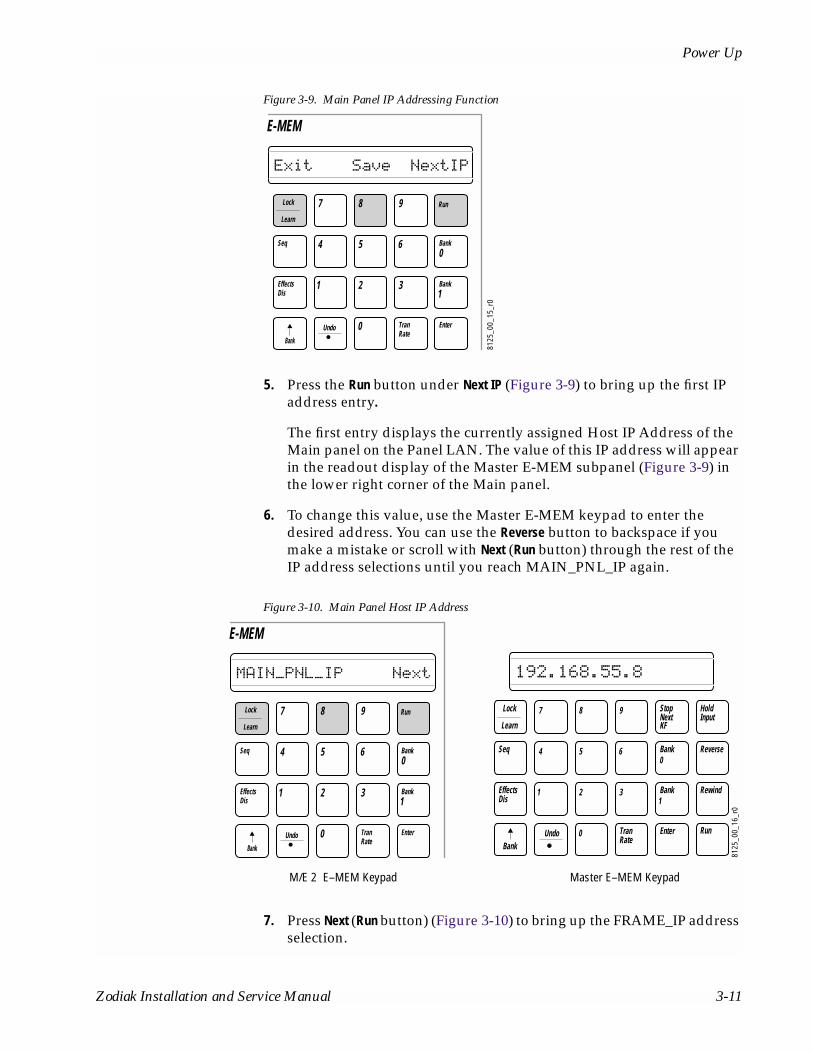
Power Up
Figure 3-9. Main Panel IP Addressing Function
5. Press the Run button under Next IP (Figure 3-9) to bring up the first IP address entry.
The first entry displays the currently assigned Host IP Address of the Main panel on the Panel LAN. The value of this IP address will appear in the readout display of the Master E-MEM subpanel (Figure 3-9) in the lower right corner of the Main panel.
6. To change this value, use the Master E-MEM keypad to enter the desired address. You can use the Reverse button to backspace if you make a mistake or scroll with Next (Run button) through the rest of the IP address selections until you reach MAIN_PNL_IP again.
Figure 3-10. Main Panel Host IP Address
7. Press Next (Run button) (Figure 3-10) to bring up the FRAME_IP address selection.
Undo
Learn
Lock
Bank
1 2 3
4 5 6
7 8 9
0
Run
Seq Bank0
EffectsDis
Bank1
TranRate
Enter
E-MEM
Exit Save NextIP
8125
_00_
15_r
0
Undo
Learn
Lock
Bank
1 2 3
4 5 6
7 8 9
0
Run
Seq Bank0
EffectsDis
Bank1
TranRate
Enter
E-MEM
MAIN_PNL_IP Next
8125
_00_
16_r
0
Run
StopNextKF
HoldInput
Reverse
Rewind
Undo
EffectsDis
1
Learn
Seq 4
0 TranRate
Enter
2 3
5 6
Bank1
Bank0
Lock 7 8 9
Bank
192.168.55.8
Master E–MEM KeypadM/E 2 E–MEM Keypad
Zodiak Installation and Service Manual 3-11

Section 3 — Configuration
8. Enter the Host IP address of the Frame on the Panel LAN. Change the values with the Master E-MEM keypad. Changing this value does not affect the actual frame IP address. It informs the Main panel of the target IP address of the frame for proper communication.
9. Press Next (Run button) to move to the MENU_IP selection. Enter the Menu panel Host IP address.
10. Press Next (Run button) to proceed to the SUBNET_MASK entry. The subnet mask should always remain at 255.255.255.0 unless you are instructed otherwise.
11. Press Next (Run button) to go to the GATEWAY entry. The Gateway should match the Frame Host IP address you have entered in Step 8 above. The frame acts as the gateway between the Main and Menu panels.
12. Scroll through and confirm the values you have entered. Press the Save (8 button) to save these values (Figure 3-9 on page 3-11).
13. Open the Main panel lid and return the Rotary Boot switch to position 0 and press the RT Panel Reset button to return to normal operation.
Video Processor Frame IP AddressesThe Video Processor frame has two Host IP addresses as explained in Network Configurations on page 3-4. The IP address for the Menu LAN (also called the Facility LAN) must be on the same network as the Menu panel (Windows 2000). In most cases, the separate Panel LAN containing the Main panel and the Frame, does not require changes and it is highly recom-mended to leave this LAN at the default addresses if possible.
Changes to the Frame are made using a web browser connected to the Menu LAN. The current Host IP address of the Frame must be known to do this procedure.
To set the Frame Menu and Panel LAN IP addresses do the following:
1. Using any web browser connected to a device on the Zodiak Menu LAN (such as the browser loaded on the Menu panel), type in the default Host IP address of the Frame on the Menu LAN (192.168.54.18) or the current IP address (if it has been changed from the default) as the following:
http://192.168.54.18
This should bring up the Zodiak Web Access page. Click on the Frame Network Addresses link to bring up the page shown in Figure 3-11.
3-12 Zodiak Installation and Service Manual

Power Up
Figure 3-11. Zodiak Web Access – Frame Network Addresses Page
2. In the Facility LAN fields, enter the desired IP address for the Host IP address of the Frame on the Menu (Facility) LAN and the Subnet Mask and Gateway IP as directed by your system administrator.
3. If you need to change the Frame Host IP address on the Panel LAN, enter the Host IP and Subnet values in the Panel LAN fields.
CAUTION When you are done filling in the addresses, double-check and record the values. This is the only access to the frame and if these IP address are lost or entered incorrectly, communication cannot be reestablished. In this case, you will need to run an emergency boot floppy disk to restore the default IP addresses as described in t Section 5 of this manual.
4. After you have confirmed and recorded the new IP addresses, press the Save New Settings button.
5. Reset the frame by pushing the frame Reset button on the front of the Control Processor/DSK/Still Store module (Figure 3-12).
Zodiak Installation and Service Manual 3-13

Section 3 — Configuration
Figure 3-12. Frame Reset Button Location
Identify New IP Addresses in Menu Panel
Once the new IP addresses are set for the Main panel and Video Processor frame, the new IP addresses must be entered into the Zodiak Menu for proper communication with the Menu panel. To identify the Frame and Main panel addresses in the Menu panel:
1. Run the Zodiak Menu application.
2. Press the Eng Setup menu selection button.
3. Press the System category menu selection button at the bottom of the screen.
4. Touch the Config selection button in the System pane on the left of the screen (Figure 3-13 on page 3-15).
8125
_00_
11_r
0
ON
OFF
8125
_00_
11r0
Frame Reset Switch
3-14 Zodiak Installation and Service Manual
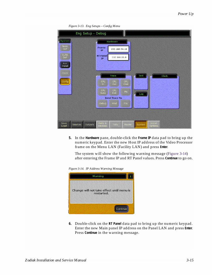
Power Up
Figure 3-13. Eng Setups – Config Menu
5. In the Hardware pane, double-click the Frame IP data pad to bring up the numeric keypad. Enter the new Host IP address of the Video Processor frame on the Menu LAN (Facility LAN) and press Enter.
The system will show the following warning message (Figure 3-14) after entering the Frame IP and RT Panel values. Press Continue to go on.
Figure 3-14. IP Address Warning Message
6. Double-click on the RT Panel data pad to bring up the numeric keypad. Enter the new Main panel IP address on the Panel LAN and press Enter. Press Continue in the warning message.
Zodiak Installation and Service Manual 3-15
Section 3 — Configuration
7. You may wait until the next step (Menu Panel IP Addresses) to restart the Menu application if you are also changing the Menu panel IP addresses through Window 2000. Otherwise, shut down the Menu application by touching the upper right corner, then restart the Menu application.
Menu Panel IP AddressesSet the Menu panel IP addresses using the standard Windows 2000 inter-face. To set the Menu panel addresses do the following.
1. Go to the following location in Windows 2000: Start\Settings\Network and Dial-up Connections.
2. Click the Local Area Connection icon to bring up the Local Area Status Dialog Box, then press the Properties button.
3. Double-click the Internet Protocol (TCP/IP) line in the list window to bring up the Internet Protocol (TCP/IP) Properties dialog box.
The default values given for the Menu panel in Table 3-1 on page 3-6 should appear here.
4. Enter the Menu panel Host IP address to conform to the network requirements for your facility.
5. Enter the Subnet mask as 255.255.255.0.
6. Enter the correct Default Gateway address for connecting to the external gateway device (refer to Connecting to an Existing Network on page 3-5).
7. Restart Window 2000 for the changes to take effect and to insert the correct gateway address into the internal routing tables.
IP Address ConfirmationTo confirm your network connections, you may perform any of the fol-lowing actions:
■ Ping between devices from the Menu panel.
■ Double-press any of the DPOP buttons to confirm the correct menu comes up on the Menu panel.
■ Change Main panel crosspoints and see video changes.
If you change IP addresses and lose communication with one or more devices, refer to Section 5 — Troubleshooting and Diagnostics for trouble-shooting tips. If you cannot recover communication or have some form of system crash and recovery is not possible, emergency reboot floppy disks have been provided for the Main panel (2 disk set) and Video Processor
3-16 Zodiak Installation and Service Manual

Software Installation
frame (1 disk). These disks will reformat the hard drives in each device and reinstall the default IP addresses. Use this recovery process only after reading the Troubleshooting section of this manual.
CAUTION The emergency floppy disks provided are for reformatting the hard drives on the specific devices only. Do not try to use these disks in any other type of computer.
Software InstallationZodiak systems are shipped with the current software version. Updates to Zodiak system software are supplied on CD-ROM, which includes an Update Tool. The Zodiak Software Update Tool installs various software components for the Menu panel, Video Processor frame, and Main panel. For the most current software installation procedures, refer to the Release Notes shipped with the software update.
Hardware Reset ProceduresDevices need to be reset after software installation, changing IP addresses, and for servicing or troubleshooting purposes.
Main Panel and Menu Panel ResetThe reset buttons for the Main panel and Menu panel are located inside the Main panel tub and are accessed by opening the top lid. There are three reset buttons, the Master Reset (left) resets the Menu and the Main panel together, the Menu Panel Reset (middle) resets the Menu panel only, and the RT (Real Time) Panel Reset (right) resets the Main panel only (Figure 3-15 on page 3-18).
Note Do not recycle power on the Main or Menu panel to reset them during a soft-ware installation. Recycling power results in an incomplete software install and produces error messages. Recycling power during a software installation necessitates a software reload, followed by a proper system reset using the Main panel Reset button.
The Boot dial switch next to the Main panel Reset button has a 0 (zero) default setting, which is used for normal software updates and system operation. Setting the Boot dial switch to position 1 (one) allows for loading boot software in the event the application crashes during installation. It boots the processor with only the operating system and an FTP server, and does not launch the Zodiak application.
Zodiak Installation and Service Manual 3-17

Section 3 — Configuration
Figure 3-15. Zodiak Main Panel Reset Switches
Video Processor Frame ResetThe reset button for the Video Processor frame is located inside the front door, on the left side of the Control Processor/DSK/Still Store module the top slot of the frame (Figure 3-16).
Next to the Reset button is a dial switch. The dial switch must be set to 0 (zero) for normal operation and software updates. This is the default set-ting. Setting this dial switch to 1 (one) allows for loading boot software. In this setting, in the event the application crashes during initialization, the processor boots with only the operating system and an FTP server, and does not launch the Zodiak application.
Figure 3-16. Frame Reset and Rotary Boot Switch
RT Panel Reset Button
Rotary Boot Switch
Master Reset Switch
Menu Panel Reset Switch
8125
_00_
17_r
0
8125
_00_
11_r
0
ON
OFF
8125
_00_
18r0
Frame Reset SwitchRotary Boot Switch
3-18 Zodiak Installation and Service Manual
Engineering Setups
Engineering SetupsZodiak inputs and outputs are connected to the rear of the Video Processor frame. These video signals need to be configured to your facility’s require-ments. Engineering setups define Zodiak system components and describe how Zodiak is cabled into a facility. Engineering setups are intended to be used and maintained by technical staff, and are designed to be set once and seldom changed. Engineering setups may be loaded and saved to disk by category, or all at once.
Note The current Zodiak system configuration settings are automatically saved to non-volatile storage when you exit an Engineering Setups menu.
Source DefinitionThe source definition tells the system which physical inputs or internal signals to use when a particular source is selected. The source definition, denoted by a source ID number, specifies how to process a signal, and what external devices and key signals, if any, are associated with that source.
Source definition defines what signals comprise each source. The default Source Select button definitions are set up at the factory such that Input 1 = Source 1, Input 2 = Source 2, etc. The Eng Setup – Sources menu is used to change source definitions. Press the Eng Setups button on the Menu panel, then touch the Sources button to display the menu (Figure 3-17 on page 3-20).
There are a total of 92 assignable sources, including internally generated signals. The sources can use, as inputs, 64 physical BNC connectors on the rear of the Video Processor frame, or internally generated signals and re-entries, such as Background mattes, black and internal Still Stores and the Program and Preview outputs from each M/E level. The internal signals are assigned in button mapping.
Zodiak Installation and Service Manual 3-19

Section 3 — Configuration
Figure 3-17. Eng Setup - Sources Menu
Direct Source Definition
To Define Direct Source Definitions:
1. Touch the source button located on the left side of the screen to be defined. You may also use the Source ID soft knob on the right to dial up the source number.
2. Touch the Engineering Name data pad at the top of the screen to name the source using the pop up alphanumeric keypad or standard keyboard.
3. Touch the Video Input data pad or use the soft knob on the right of the screen to enter the number of the physical BNC connector on the rear of the frame the source will use for video. The backplane’s individual video connectors are labeled sequentially Video Inputs 1 through 64. The change is immediate and can be viewed on a connected monitor.
4. In the Source Type pane, define the source as Direct. The Router, DPM Physical, DPM Logical, and Device buttons are used to setup a source as an external device, including GPI and Peripheral Bus II controlled devices. These choices are not enabled in this release.
3-20 Zodiak Installation and Service Manual

Engineering Setups
5. In the Key pane, define the source as either Linear, No Key or 0:4:4 with the touch buttons.
If you have selected Linear, press the Shaped button if the incoming key signal is shaped.
If the source has been defined as Linear or 0:4:4 (a compressed chroma key signal processed in the 8950ADC A-D Converter module), you will need to identify the key source input. Touch the Key Input data pad to bring up the numeric keypad or use the soft knob to enter the number of the BNC connector to be used.
6. If desired, define Clip Hi and Clip Lo values (used when a fixed linear key is selected for that source) with the labeled soft knobs and data pads. These can be changed by selecting an adjustable linear key through the switcher controls.
When you are done defining a source, the corresponding Description field for each source will show the Engineering Name assigned, the Video Input, the Key Input (if defined), and whether the Linear key signal is defined as shaped or unshaped.
7. Do this procedure for each switcher source available.
8. Exit the menu by touching the menu name located at the top of the screen.
Output Configuration
Program and Preview OutputsZodiak Program and Preview outputs are fed to dedicated BNCs on the rear of the Video Processor frame. These output destinations cannot be changed. The only configuration necessary is defining the clean feed con-figuration for the downstream keys that will appear on either of the Program outputs (PGM A and PGM B). This is done with the DSK menu. This menu allows selection of any of the three downstream keys (DSK 1, 2 and 3) to be allowed to appear (or not appear) on the PGM A and PGM B outputs of the switcher.
From the Home menu, select DSK. This will bring up the DSK Clean Feed menu shown in Figure 3-18 on page 3-22. Select the keys you wish to appear on the Program Out A and Program Out B signals. Any combina-tion is selectable. In the example shown, the Program Out A has all three downstream keyers enabled, and the Program Out B has been configured with no downstream keyers (clean feed).
Zodiak Installation and Service Manual 3-21

Section 3 — Configuration
Figure 3-18. DSK Clean Feed Menu
Aux Bus Configuration
There are 9 Aux buses in the 2.5-M/E system and 13 in the 3-M/E system. The Aux Bus video outputs are fed to BNC connectors on the rear of the Video Processor frame. The Aux Bus outputs can be mapped to any of the logical Aux Buses as desired. This is done with the Eng Setup – Outputs menu.
Other Aux Bus attributes such as bus to panel delegation and Aux Pair con-figuration are covered in menus outside of Eng Setups and will be referred to in this section.
Mapping Aux Bus Physical OutputsTo map the Aux Bus outputs, press the Eng Setup button on the Menu panel, then press the Outputs touch button to display the menu (Figure 3-19 on page 3-23). Depending on the type of equipment the Aux Bus is feeding, some Aux Bus attributes are configurable, such as assigning Aux Pairs.
1. Select a physical Aux Bus number from the Physical Outputs pane on the left of the screen.
2. Select an Aux Bus number from the Logical Aux Bus pane on the left to assign it to the physical output.
3-22 Zodiak Installation and Service Manual

Engineering Setups
3. Touch the Logical Aux Bus Name data pad to bring up the alphanumeric keypad. Enter the desired name of the Aux Bus and press Enter. The name of the Logical Aux Bus should appear in the assigned physical output box.
4. Continue to name and assign each Aux Bus you wish to use to a physical output.
Once the Aux Bus physical assignments are made, you will need to del-egate each Aux Bus to the Aux 1 – 9 buttons on the PVW/AUX delega-tion subpanel. Refer to Aux Bus Delegation in the Zodiak User Manual.
Figure 3-19. Output Mapping Menu
Defining Aux Pairs
Physical Aux Buses can be also be configured as Aux Pairs in the Outputs menu. Aux Pairs are two physical Aux Buses that have been configured to send a video and associated key signal to an external device, such as a DVE, usually for an effects send effect. Pairing of the video and key signal to be used on the Aux bus is defined in the Sources menu as explained earlier. The Aux Pair can be defined in the Outputs menu and also be named and configured for shaping or unshaping for effects send.
Aux Buses 1 and 2, 3 and 4, 6 and 7, 8 and 9, 10 and 11, 12 and 13 can be paired. Note that Aux Bus 5 cannot be paired with any other Aux Bus. In a 2.5-M/E switcher, only two pairs (6 and 7, 8 and 9) will have effects send
Zodiak Installation and Service Manual 3-23
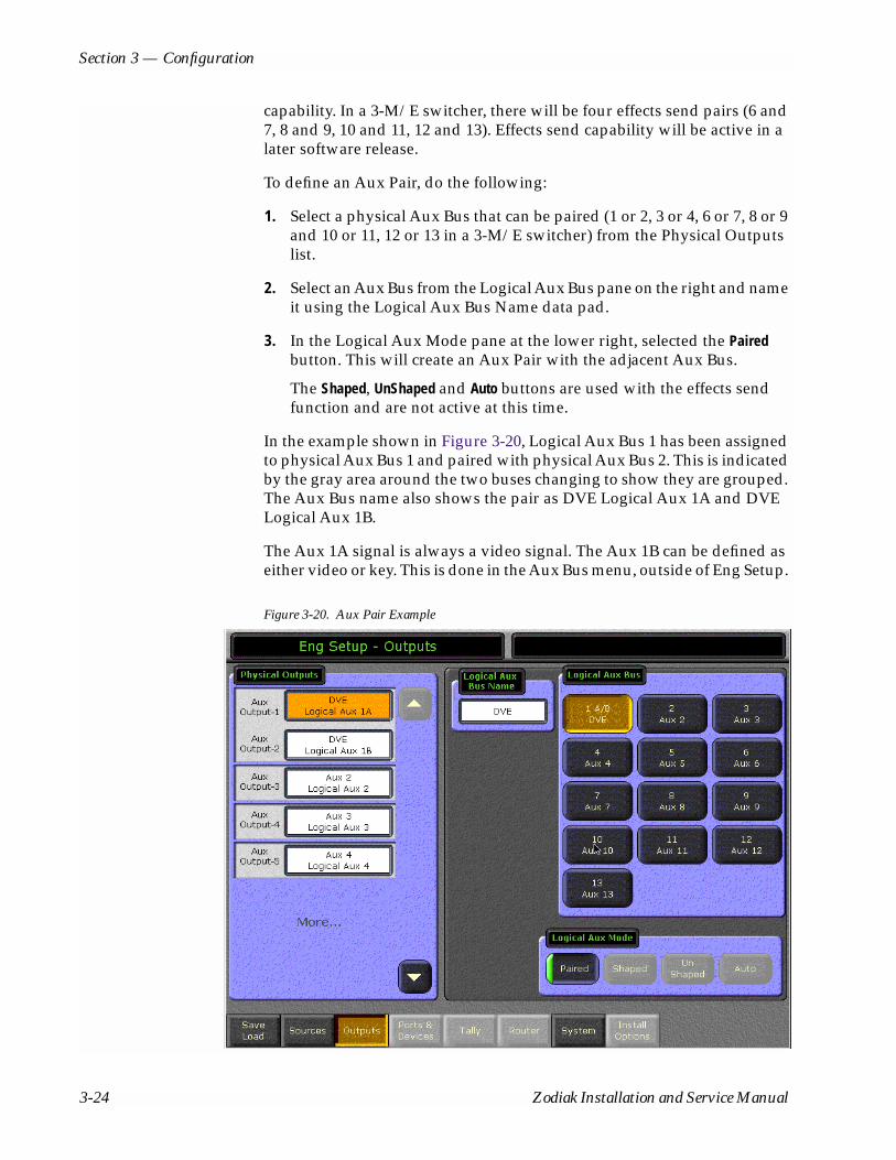
Section 3 — Configuration
capability. In a 3-M/E switcher, there will be four effects send pairs (6 and 7, 8 and 9, 10 and 11, 12 and 13). Effects send capability will be active in a later software release.
To define an Aux Pair, do the following:
1. Select a physical Aux Bus that can be paired (1 or 2, 3 or 4, 6 or 7, 8 or 9 and 10 or 11, 12 or 13 in a 3-M/E switcher) from the Physical Outputs list.
2. Select an Aux Bus from the Logical Aux Bus pane on the right and name it using the Logical Aux Bus Name data pad.
3. In the Logical Aux Mode pane at the lower right, selected the Paired button. This will create an Aux Pair with the adjacent Aux Bus.
The Shaped, UnShaped and Auto buttons are used with the effects send function and are not active at this time.
In the example shown in Figure 3-20, Logical Aux Bus 1 has been assigned to physical Aux Bus 1 and paired with physical Aux Bus 2. This is indicated by the gray area around the two buses changing to show they are grouped. The Aux Bus name also shows the pair as DVE Logical Aux 1A and DVE Logical Aux 1B.
The Aux 1A signal is always a video signal. The Aux 1B can be defined as either video or key. This is done in the Aux Bus menu, outside of Eng Setup.
Figure 3-20. Aux Pair Example
3-24 Zodiak Installation and Service Manual
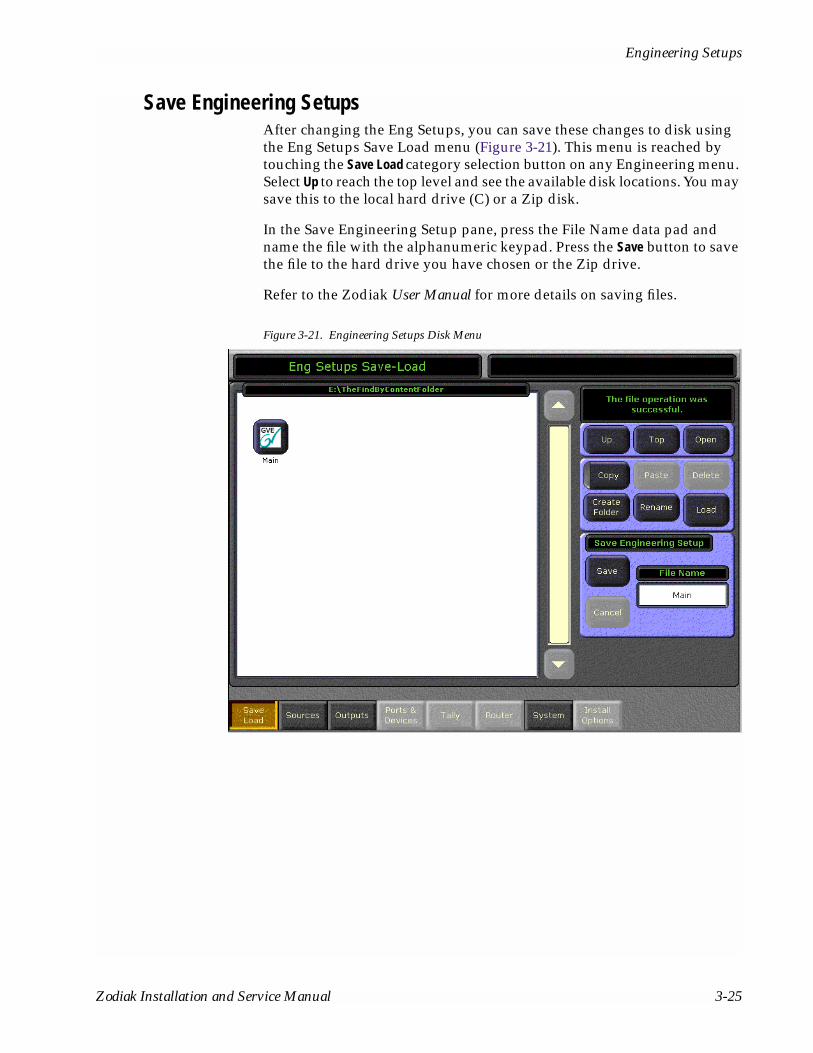
Engineering Setups
Save Engineering SetupsAfter changing the Eng Setups, you can save these changes to disk using the Eng Setups Save Load menu (Figure 3-21). This menu is reached by touching the Save Load category selection button on any Engineering menu. Select Up to reach the top level and see the available disk locations. You may save this to the local hard drive (C) or a Zip disk.
In the Save Engineering Setup pane, press the File Name data pad and name the file with the alphanumeric keypad. Press the Save button to save the file to the hard drive you have chosen or the Zip drive.
Refer to the Zodiak User Manual for more details on saving files.
Figure 3-21. Engineering Setups Disk Menu
Zodiak Installation and Service Manual 3-25

Section 3 — Configuration
Daily SetupsDaily Setups are available to operators as well as facility engineers. These settings may need to be changed on a session by session basis. The Zodiak system supports Suite Preferences and User Preferences.
The engineer in charge of a Zodiak system may wish to create and save a standard set of Suite and User Preferences onto disk so the system can be easily restored to a known state. This can be accomplished using Zodiak Profiles (not to be confused with a Profile VDR) and the Daily Setups Disk menu. In particular, the following items will help you restore the system to a known state for troubleshooting and testing.
Suite Preferences (Suite Profile)
■ E-MEM Level Grouping,
■ Default Keyframe,
■ Video Settings, and
■ GPI In Settings.
User Preferences (User Profile)
■ Button Mapping, and
■ Shift Prefs.
(Daily Setups Disk Menu)
■ Source Memory
Refer to the separate Zodiak User Manual for information about Daily Setup configuration.
3-26 Zodiak Installation and Service Manual

Panel Adjustments
Panel AdjustmentsCalibration procedures are included in this section for the Main panel lever arms and joystick and the Menu panel touch screen. It is recommended to run the calibration procedures when the switcher is installed and in con-junction with the Troubleshooting information in this manual if problems with either of these areas occur.
Lever Arm and Joystick CalibrationThe Main panel lever arms and joystick can be calibrated from the Main panel.
1. Open the main control panel to access the Boot dial rotary switch and Rt Panel (real-time panel) reset push button (refer to Figure 3-15 on page 3-18). Rotate the switch to position 9 then reset the control panel.
When the panel comes up it will enter Calibration Mode as shown in the M/E 1 E-MEM display. Use the M/E 2 E-MEM display and buttons to step through the calibration process (see Figure 3-22). During the procedure, the Master E-MEM display will show the current minimum and maximum values for the selected lever arm or joystick positions.
Figure 3-22. M/E 2 and Master E-MEM Displays in Calibration Mode
2. Follow the steps shown in Figure 3-23 on page 3-28 to calibrate the M/E 3, M/E 2, and M/E 1 lever arms respectively. Repeat steps C through F to calibrate the lever arms for M/E 2 and M/E 1.
Undo
Learn
Lock
Bank
1 2 3
4 5 6
7 8 9
0
Run
Seq Bank0
EffectsDis
Bank1
TranRate
Enter
E-MEM
IP Calib Exit
8125
_00_
22_r
0Run
StopNextKF
HoldInput
Reverse
Rewind
Undo
EffectsDis
1
Learn
Seq 4
0 TranRate
Enter
2 3
5 6
Bank1
Bank0
Lock 7 8 9
Bank
Master E–MEM KeypadM/E 2 E–MEM Keypad
Mi 6000 Mx 10200
Zodiak Installation and Service Manual 3-27

Section 3 — Configuration
Figure 3-23. Lever Arm Calibration Procedure
3. After calibrating the M/E 1 lever arm and selecting the Next button, you will see the Joystick calibration display. Follow the steps shown in Figure 3-24 on page 3-29 to calibrate the Joystick.
Undo
Learn
Lock
Bank
1 2 3
4 5 6
7 8 9
0
Run
Seq Bank0
EffectsDis
Bank1
TranRate
Enter
E-MEM
IP Calib Exit
Undo
Learn
Lock
Bank
1 2 3
4 5 6
7 8 9
0
Run
Seq Bank0
EffectsDis
Bank1
TranRate
Enter
E-MEM
Exit Save NextCal
Undo
Learn
Lock
Bank
1 2 3
4 5 6
7 8 9
0
Run
Seq Bank0
EffectsDis
Bank1
TranRate
Enter
E-MEM
ME3 Cal Next
Undo
Learn
Lock
Bank
1 2 3
4 5 6
7 8 9
0
Run
Seq Bank0
EffectsDis
Bank1
TranRate
Enter
E-MEM
MoveToLower Press
Undo
Learn
Lock
Bank
1 2 3
4 5 6
7 8 9
0
Run
Seq Bank0
EffectsDis
Bank1
TranRate
Enter
E-MEM
MovToUpper Press
Undo
Learn
Lock
Bank
1 2 3
4 5 6
7 8 9
0
Run
Seq Bank0
EffectsDis
Bank1
TranRate
Enter
E-MEM
ME3 Cal Next
8125
_00_
24r0
A. Select Calibration
B. Select Next Cal
C. Select Cal
D. Move M/E 3 transition arm to low position and select Press
E. Move M/E 3 transition arm to upperposition and select Press
F. Select Next
3-28 Zodiak Installation and Service Manual

Panel Adjustments
Figure 3-24. Joystick Calibration Procedure
Undo
Learn
Lock
Bank
1 2 3
4 5 6
7 8 9
0
Run
Seq Bank0
EffectsDis
Bank1
TranRate
Enter
E-MEM
JoyX Cal Next
Undo
Learn
Lock
Bank
1 2 3
4 5 6
7 8 9
0
Run
Seq Bank0
EffectsDis
Bank1
TranRate
Enter
E-MEM
JoyY Cal Next
Undo
Learn
Lock
Bank
1 2 3
4 5 6
7 8 9
0
Run
Seq Bank0
EffectsDis
Bank1
TranRate
Enter
E-MEM
JoyZ Cal Next
Undo
Learn
Lock
Bank
1 2 3
4 5 6
7 8 9
0
Run
Seq Bank0
EffectsDis
Bank1
TranRate
Enter
E-MEM
Mv2All Sho Press
Undo
Learn
Lock
Bank
1 2 3
4 5 6
7 8 9
0
Run
Seq Bank0
EffectsDis
Bank1
TranRate
Enter
E-MEM
Mv2All Sho Press
Undo
Learn
Lock
Bank
1 2 3
4 5 6
7 8 9
0
Run
Seq Bank0
EffectsDis
Bank1
TranRate
Enter
E-MEM
Mv2All Sho Press
Undo
Learn
Lock
Bank
1 2 3
4 5 6
7 8 9
0
Run
Seq Bank0
EffectsDis
Bank1
TranRate
Enter
Run
Bank0
Bank1
Enter
Master E-MEM Display
Mn 6000 Mx 10200
Undo
Learn
Lock
Bank
1 2 3
4 5 6
7 8 9
0
Run
Seq Bank0
EffectsDis
Bank1
TranRate
Enter
E-MEM
Exit Save Press
A. Select Calibration
D. With JoyY in the display, select Cal
B. Move the Joystick fully left then right (X axis) toset minimum and maximum values (approximatevalues shown below).
C. Select Sho
H. Select Save
G. Rotate the Joystick clockwise and counter-clockwiseto set the Z axis range then select Press
E. Adjust the Joystick range vertically (Y axis) thenselect Sho
F. With JoyZ in the display, select Cal
8125
_00_
15_r
0
Zodiak Installation and Service Manual 3-29
Section 3 — Configuration
4. Return the Boot dial rotary switch to position 0 and reboot the control panel by pressing the RT Panel Reset button on the right.
Menu Panel Touch Screen Calibration
Touch Screen CalibrationThe Menu panel display is aligned using a software tool provided by the display manufacturer using standard Windows 2000 procedures. To cali-brate the Menu panel display, open My Computer\Control Panel\ELO Touchscreen.
Press the General tab and then press the Align button. Follow the instructions displayed on the screen.
Refresh Frequency Adjustment To adjust the refresh frequency:
1. Open My Computer\Control Panel\Display.
2. Press the Settings tab and then press the Advanced button.
3. Press the Monitor tab and adjust the frequency rate. Refresh frequency should be set at 60Hz or 75 Hz.
3-30 Zodiak Installation and Service Manual

Section 4Maintenance
IntroductionThis section provides routine maintenance information for servicing the Zodiak Video Production Switcher, including the Video Processing Frame, Control Surface components, and the Main panel and Video Processor frame power supplies.
Servicing PrecautionsBefore performing any type of maintenance or troubleshooting of the Zodiak Video Production Switcher, read the complete Safety Summary at the front of this manual. The Safety Summary describes all of the pertinent safety issues and recommended precautions for working with the Zodiak Video Production Switcher.
Zodiak Installation and Service Manual 4-1

Section 4 — Maintenance
Main Panel MaintenanceThe Main panel in the Zodiak Video Production Switcher requires no routine maintenance.
Cleaning If the Main panel requires cleaning, use a damp (not wet) cloth. Do not spray anything directly on the panel surface.
Replacing Circuit BoardsThere are no user-serviceable circuit boards inside the Main panel. If the Crosspoint Switch board, M/E Switch board, or Real Time Processor board (Figure 1-3 on page 1-6) needs repair, it should be removed and replaced. Follow the steps below to remove and replace a circuit boards.
WARNING Shut off power to the Main panel when removing or replacing Main panel circuit boards.
Crosspoint Switch Board
To remove and replace the Crosspoint Switch Board on the Main panel lid:
1. Turn off the power to the power supplies inside the Main panel tub (Figure 1-3 on page 1-6).
2. Remove the three screws securing the Real Time Processor board’s metal enclosure to the Main panel tub and remove the enclosure.
3. Disconnect the ribbon cable attached to the Real Time Processor board by simultaneously pushing the cable connector’s left and right ejector tabs outward and pulling the cable up and out of the connector.
4. Support the board as you remove the 20 screws that secure the Crosspoint Switch board to the Main panel lid. Carefully remove the board.
5. Install the replacement board by reversing Step 4 through Step 2 and turn the power back on to the Main panel.
6. Make sure you have not left any spare hardware or tools inside the panel and the replacement board is cabled correctly.
7. Test the new board for proper operation.
4-2 Zodiak Installation and Service Manual
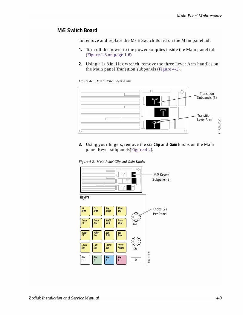
Main Panel Maintenance
M/E Switch Board
To remove and replace the M/E Switch Board on the Main panel lid:
1. Turn off the power to the power supplies inside the Main panel tub (Figure 1-3 on page 1-6).
2. Using a 1/8 in. Hex wrench, remove the three Lever Arm handles on the Main panel Transition subpanels (Figure 4-1).
Figure 4-1. Main Panel Lever Arms
3. Using your fingers, remove the six Clip and Gain knobs on the Main panel Keyer subpanels(Figure 4-2).
Figure 4-2. Main Panel Clip and Gain Knobs
TransitionLever Arm
8125
_00_
20_r
0
TransitionSubpanels (3)
IntDPM
ExtDPM
KeyInvert
ShowKey
MatteFill
FreezeFill
InhibitMask
ForceMask
Video
KeyFreeze
KeyKeySplit
KeyPrior
LinearKey
LumKey
Key
ChromaKey
PresetPattern
Key Key2
Key3 41 On
Keyers
Clip
Gain
M/E KeyersSubpanel (3)
8125
_00_
19_r
0
Knobs (2)Per Panel
Zodiak Installation and Service Manual 4-3

Section 4 — Maintenance
4. In order for the board to clear the tension spring that holds the Main panel open, the spring must be released. Using a 7/16 in. screwdriver, remove the 1/4 in. nut and washer on the right tension spring and lay the spring down inside the tub.
5. Remove the three screws securing the Real Time Processor board’s metal enclosure to the Main panel tub and remove the enclosure.
6. Disconnect the ribbon cable attached to the Real Time Processor board by simultaneously pushing the cable connector’s left and right ejector tabs outward and pulling the cable up and out of the connector.
7. Disconnect the Joystick cable attached to the M/E Switch board by pulling the Joystick cable connector down and out of the board connector.
Note The Joystick cable connector is clearly labeled on the bottom right of the M/E Switch board.
8. Support the board as you remove the 20 screws that secure the M/E Switch board to the Main panel lid. Carefully remove the board.
9. Install the replacement board by reversing Step 8 through Step 2 and turn the power back on to the Main panel.
10. Make sure you have not left any spare hardware or tools inside the panel and the replacement board is cabled correctly.
11. Test the new board for proper operation.
Real Time Processor Board
To remove and replace the Real Time Processor board inside the Main panel tub:
1. Turn off the power to the power supplies inside the Main panel tub (Figure 1-3 on page 1-6).
2. Disconnect all cables on the rear of the Main panel that are behind the Real Time Processor board (Figure 2-7 on page 2-7).
3. Remove the front three screws securing the Real Time Processor board’s metal enclosure to the Main panel tub and remove the enclosure.
4. Disconnect the ribbon cables attached to the Crosspoint Switch board and M/E Switch board by simultaneously pushing the cable connector’s left and right ejector tabs outward and pulling the cables up and out of the connectors.
5. Disconnect the connectors from the power supplies.
4-4 Zodiak Installation and Service Manual

Main Panel Maintenance
6. Remove the two screws on the middle of the board and retain.
7. Remove the two screws on the back wall of the metal enclosure and retain.
8. Carefully slide the board forward and out of the tub.
9. Install the replacement board by reversing Step 8 through Step 2 and turn the power back on to the Main panel.
10. Make sure you have not left any spare hardware or tools inside the panel and the replacement board is cabled correctly.
11. Test the new board for proper operation.
Power Supply ReplacementThe Main panel has power supplies in the Main panel tub (Figure 1-3). The power supplies do not have user-serviceable fuses. The entire power supply must be removed and replaced if it fails. Follow the steps below to remove and replace a power supply.
To replace either power supply:
1. Turn off power to both power supplies in the Main panel (Figure 1-3 on page 1-6).
2. Disconnect the AC line cord on the rear of the Main panel (Figure 2-7 on page 2-7).
3. Disconnect the power supply connector that is attached to the side of the Real Time Processor board.
4. Using your fingers or a flat blade screwdriver, remove the four captive screws securing the power supply to the tub.
5. Remove the power supply.
6. Install the replacement power supply by reversing Step 5 through Step 2 and turn the power back on to the Main panel.
7. Make sure you have not left any spare hardware or tools inside the panel and the replacement power supply is cabled correctly.
Zodiak Installation and Service Manual 4-5

Section 4 — Maintenance
Fuse Replacement
Note It is not necessary to power down the system to replace a fuse.
1. Check fuse status. LEDs located on the front of the Real Time Processor board (Figure 1-3 on page 1-6) indicate fuse status. A red LED indicates that a fuse needs to be replaced.
2. To replace a fuse, remove the front three screws securing the Real Time Processor board’s metal enclosure, remove the enclosure, and replace the fuse.
Note A fuse rating is label is adjacent to each fuse.
3. Replace the metal enclosure and screws. A green LED indicates that the fuse is working properly.
Button LED ReplacementThe buttons on the Main panel use long-life Light Emitting Diodes (LEDs) which make lamp failure unlikely. If an LED fails to illuminate, it should be replaced.
To remove and install an LED:
1. Turn off the Main panel power supplies (Figure 1-3).
2. Using your fingers or adjustable jaw pliers, pull the keycap up and out of the panel (Figure 4-3).
4-6 Zodiak Installation and Service Manual

Menu Panel Maintenance
Figure 4-3. LED Replacement
3. Pull the LED out of the switch using needle nose pliers.
4. Carefully replace with a new LED. Align the pins in the switch as shown in Figure 4-3.
5. Re-insert the keycap so the large notches are on the front and back sides of the switch.
6. Turn on the Main panel power supplies.
Menu Panel MaintenanceThe Menu panel requires no routine maintenance. Calibration procedures for the touch screen are available through Windows 2000 on the Menu panel (seeTouch Screen Calibration on page 3-30).
CleaningClean the Menu panel and touch screen with household glass cleaner and paper towels. Always dampen the paper towel and then clean the touch screen. Do not spray cleaner directly on the Menu panel or touch screen.
Keycap
Lamp
Switch
Insert keycap withnotches on frontand back sides.
8125
_00_
21_r
0
Rear of panel
Insert LED with flatside oriented as shown.
Zodiak Installation and Service Manual 4-7

Section 4 — Maintenance
Video Processor Frame MaintenanceCAUTION Do not operate the Video Processor frame with its door open for an extended
period of time. Failure to observe this precaution may result in improper air flow and cause components to overheat.
Air Filter CleaningThe Video Processor frame contains a removable air filter that reduces the accumulation of dust on the circuit boards. The air filter should be removed and cleaned periodically.
To clean the frame air filter:
1. Open the door of the Video Processor frame and locate the air filter (Figure 4-4).
2. Remove the filter by pulling the white plastic handle at the front center of the filter. Pull the filter out slowly, making sure the metal netting on the right of the filter does not catch on the frame.
3. Vacuum the filter and/or wash it in a warm water soap (not detergent) solution.
4. Rinse the filter thoroughly with fresh water, and air dry completely.
5. When the filter is completely dry, reinstall it into the frame with the metal netting to the right. Close the door of the frame.
Figure 4-4. Video Processor Frame Air Filter81
25_0
0_08
_r0
ON
OFF
Air Filter
Air Filter Handle
4-8 Zodiak Installation and Service Manual

Replacement Parts Lists
Removing and Replacing ModulesModules in the Zodiak Video Processor frame are not designed to be repaired in the field unless a repair is authorized by Customer Service, usually in the form of a Field Modification Note. Failed modules should be replaced.
If you need to remove or replace a module in the Video Processor frame, refer to the module location illustrations in Figure 2-25 (frame front), Module Insertion on page 2-25 and Module Removal on page 2-25 in Section 2-Installation. All frame modules can be removed and replaced without powering down the frame, however, removing the Control Pro-cessor board will shut down the power.
CAUTION All modules are subject to static damage when removed from the frame. Always use recommended anti-static precautions when handling modules.
Field Upgrading of ModulesZodiak frame modules are designed with field programmable circuitry that allows firmware upgrades to be done in the field over the Facilities LAN during a software download. Any specific upgrade instructions will be included in the Release Notes that accompany each software update.
Power Supply MaintenanceFor proper operation, the Zodiak Video Processor frame must have one power supply for the 2.5-M/E and two power supplies for the 3-M/E installed and operating at all times. Frame power supplies are not designed to be serviced in the field. If a power supply fails, replace the entire module.
To install or remove a Video Processor frame power supply, see Power Supply Installation on page 2-24 and Power Supply Removal on page 2-24.
Replacement Parts Lists Contact your Grass Valley Group representative for a complete listing of the available Field Replaceable Units (FRUs) for the Zodiak Video Produc-tion Switcher.
Zodiak Installation and Service Manual 4-9

Section 4 — Maintenance
4-10 Zodiak Installation and Service Manual

Appendix
Specifications Table A-1. Zodiak System Specifications
Power
Video Processor Frame Power Supply 100-125 VAC or 200-250 VAC autorange, 50-60 Hz power factor corrected
Power Consumption 2.5-M/E: 300 W (typical)3-M/E: 400 W (typical)
Main Panel Power Supply 100-125 VAC or 200-250 VAC autorange, 50-60 Hz power factor corrected
Power Consumption 150 W (typical)
Environmental
Temperature Range
Frame, Menu Panel Specification: 20º to 30º C (68º to 86º F)Operational: 0º to 40º C (32º to 104º F)
Main Panel Specification: 20º to 30º C (68º to 86º F)Operational: 0º to 35º C (32º to 95º F)
Relative Humidity Up to 95% (non-condensing)
Serial Digital Video Inputs
Number 64 non-looping
Type of Connectors 75 ohm BNC, (SMPTE 259M)
Nominal Amplitude 800 mV peak-to-peak terminated
Return Loss > 15 dB, 5 MHz to 270 MHz
Channel Coding Conforms to SMPTE RP-259M
Ancillary Data Passed from A background to program outputs
Input Impedance 75 ohm, self terminating
Autotiming Range ± 10 microsecond1
Maximum Cable Length Equalized(Belden 8281 type cable)
225 m (738 ft)
Number of Bits 10
Serial Digital Video Outputs
Number 26 outputs (3-M/E), 2 BNCs per output (52 BNCs)
Type of Connectors 75 ohm BNC, self terminating (SMPTE 259M)
Amplitude 800 mV peak-to-peak across 75 ohm ± 10% (SMPTE 259M)
Return Loss > 15 dB, 5 MHz to 270 MHz
Rise and Fall Times (between 20% and 80% amplitude points)
Between 400 picosecond and 1.5 nanosecond across 75 ohm termination
Timing Jitter 0.2 UI (SMPTE RP184-1996 method)
Channel Coding Conforms to SMPTE RP-259M
Output Impedance 75 ohm
Zodiak Installation and Service Manual A-1

Appendix — Specifications
Ancillary Data Passed from A background to program outputs
DC Offset on Output < 50 mV across 75 ohm termination
Number of Bits 10
Number of Out[puts 2 BNC connectors per channel
Analog Reference Input
Black Composite Color Black (NTSC or PAL), 525 (60 Hz) or 625 (50 Hz)
Connectors Two 75 ohm BNC
Return Loss > 40 dB to 5 MHz
Impedance 75 ohm loop through
System Timing
Switcher Output Delay 53 microsecond1
1 Preliminary
Table A-2. Zodiak Mechanical Specifications
Component Depth Width Height Weight 1 Rack Units
Standard
Video Processor Frame 562 mm / 22.13 in.2 483 mm / 19.0 in.3 311 mm / 12.25 in. 36 kg / 79lb 7
Main Panel 476 mm / 18.75 in.4, 5 1041 mm / 40.97 in. 148 mm / 5.82 in.6 39 kg / 86 lb N/A
Menu Panel7 109 mm / 4.30 in. 375 mm / 14.75 in.8 257 mm / 10.1 in. 7.7 kg / 17 lb N/A
Options
KAL-24AUX1 Remote Aux Panel 51 mm / 2.0 in. 482 mm / 19.0 in. 45 mm / 1.75 in. 1.02 kg / 2.25 lb 1
KAL-24AUX2 Remote Aux Panel 64 mm / 2.5 in. 482 mm / 19.0 in. 89 mm / 3.5 in. 2.04 kg / 4.5 lb 2
KAL-24AUX3 Remote Aux Panel 64 mm / 2.5 in. 482 mm / 19.0 in. 133 mm / 5.25 in. 3.06 kg / 6.75 lb 3
KAL-32AUX1 Remote Aux Panel 133 mm / 5.25 in. 482 mm / 19.0 in. 44 mm / 1.75 in. 0.93 kg / 2.06 lb 1
KAL-32AUX2 Remote Aux Panel 108 mm / 4.25 in. 482 mm / 19.0 in. 89 mm / 3.5 in. 1.02 kg / 2.25 lb 2 1 All weights approximate. 2 Allow an extra 102 mm (4.0 in.) for cable. 3 Allow an extra 102 mm (4.0 in.) on the left and right of the frame for air flow. 4 Allow a minimum of 152 mm (6.0 in.) of clear space at the rear of the Main panel below the mounting surface for proper cable clearance and air flow. Allow an extra 203 mm (8.0 in.) to 254 mm (10.0 in.) of mounting surface behind the Main panel for peripheral components. 5 Indicated measurement is for the lid. Refer to installation detail for tub measurements. 6 Add 6 mm (0.25 in.) for rubber feet on bottom of tub if required. Indicated measurement is from bottom surface of tub to top surface of lid. 7 Not including mounting bracket. 8 Allow an extra 147 mm (5.8 in.) clearance for the CD drawer and fan exhaust.
Table A-1. Zodiak System Specifications - (continued)
A-2 Zodiak Installation and Service Manual

Index
Numerics2.5-M/Ecable 2-28configuration 1-8keycap replacement 2-9power supply 1-9replacement parts 4-9standard features 1-1upgrade kit 2-8
24-Crosspoint Remote Aux panelcable polarity 2-14communications bus 2-13connections 2-12installation 2-11joystick override 2-13power supply 2-14
32-Crosspoint Remote Aux panelAC power 2-16connections 2-15installation 2-15joystick override 2-16LAN 2-15
3-M/Ecable 2-28configuration 1-8power supply 1-9replacement parts 4-9standard features 1-2
AAC power
32-Crosspoint Remote Aux panel 2-16accessing Main panel components 1-5air filter 4-8architecture
system 1-11
BBNC
inputs 2-33outputs 2-33
buttonCross Over 2-30Main panel Reset 3-17Menu panel Reset 3-17
Ccable
2.5-M/E 2-2824-Crosspoint Remote Aux panel cable
polarity 2-143-M/E 2-28control surface 2-28Ethernet specifications 2-30Main panel 2-28Menu panel 2-28polarity 2-30supplied 2-29USB 2-4video 2-33Video Processor frame 2-28Zip drive 2-28
cablingcontrol surface 2-28
calibrationjoystick 3-17, 3-27lever arm 3-17, 3-27Menu panel 3-27
Canadian EMC notice of compliance ixCD-ROM
installation 2-7location 1-6Menu panel 2-17
certifications and compliances ixChroma Keyers option
Zodiak Installation and Service Manual Index-1

Video Processor frame 1-9cleaning
Main panel 4-2Menu panel 4-7
communications bus24-Crosspoint Remote Aux panel 2-13
component accessMain panel 1-5
componentssystem 1-4
configuration2.5-M/E 1-83-M/E 1-8basic steps 3-1LAN 2-29Remote Aux panel 3-27video 2-33
connections24-Crosspoint Remote Aux panel 2-1232-Crosspoint Remote Aux panel 2-15Main panel 2-5Menu panel 2-17Video Processor frame 2-23
controlcontrol surface cabling and control 2-28Ethernet 2-29GPI 2-29parallel 2-29serial 2-29system 1-14, 2-29Tally 2-29USB 2-29
control panelLAN 2-30
control surfacecabling 2-28cabling and control 2-28defined 1-4installation 2-3
Cross Over button 2-30Main panel 2-30Menu panel 2-30
crosspoint switch boardremoval and replacement 4-2
Ddaily setups 3-26dimensions
Main panel 2-5Menu panel 2-18Video Processor frame 2-21
documentationonline ii
EEN55103-1/2 Class A warning ixengineering setups 3-19Ethernet
cables 2-30control 2-29hub 2-31LAN 2-30switch 2-31switch specifications 2-30
external interfacesinterfaces supported 1-3
Ffacility
configuration example 1-10FAQ database iiFCC emission control ixFCC emission limits xfeatures
2.5-M/E 1-13-M/E 1-2system 1-1
filter 4-8flange
Main panel 2-4frame
described and illustrated 1-8frequency
adjusting 3-30frequently asked Questions
web siteFAQ database ii
fuse
Index-2 Zodiak Installation and Service Manual
Main panel, replacement 4-6
GGPI
control 2-29Grass Valley Group
website ii
Hhot swapping modules 1-8hub, Ethernet 2-31
Iinitialization
indicators 3-3inputs
BNC 2-33video 2-33
installation24-Crosspoint Remote Aux panel 2-1132-Crosspoint Remote Aux panel 2-15CD-ROM and Zip drive 2-7conrol surface 2-3Main panel 2-4Menu panel 2-17pre-installation procedures 2-1recommended tasks 2-2Remote Aux panel 2-11Video Processor frame 2-21Zip drive 2-4
interfaces supportedexternal interfaces 1-3
IP addressVideo Processor frame 3-7
Jjoystick
24-Crosspoint Remote Aux panel joystick override 2-13
calibration 3-17, 3-27override 2-16
Kkeycap
replacement 2-9
LLAN
32-Crosspoint Remote Aux panel 2-15configuration 2-29control panel 2-30Link LEDs 2-30requirements 2-30switch 2-30switches and hubs 2-31
LEDLink LEDs and cable polarity 2-30replacement 4-6
lever armcalibration 3-17, 3-27
Link LEDsLAN 2-30Main panel 2-30Menu panel 2-30
MM/E switch board
removal and replacement 4-3Main panel
cabling 2-28cleaning 4-2component access 1-5connections 2-5Cross Over button 2-30described and illustrated 1-5dimensions 2-5flange 2-4installation 2-4LED replacement 4-6Link LEDs 2-30maintenance 4-2options 1-7, 2-8pinouts 2-7power supply replacement 4-5Remote Aux panel option 2-11replacing circuit boards 4-2Reset button 3-17
Zodiak Installation and Service Manual Index-3
upgrade kit 2-8ventilation 2-5
maintenance 4-1Main panel 4-2Menu panel 4-7Video Processor frame 4-8
Menu paneladjusting frequency 3-30cabling 2-28calibration 3-27CD-ROM 2-17cleaning 4-7connections 2-17Cross Over button 2-30described and illustrated 1-6dimensions 2-18installation 2-17Link LEDs 2-30maintenance 4-7mounting options 2-18orientation 1-6pinouts 2-20power 1-5Reset button 3-17ventilation 2-20
modulefield upgrade 4-9hot swapping 1-8installation 2-25Video Processor frame, replacing 4-9
mountingMenu panel options 2-18
Oonline documentation iioptions
Main panel 1-7, 2-8Remote Aux panel 2-11system 1-3Video Processor frame 1-9, 2-24
outputsBNC 2-33video 2-33
Ppanel
2.5-M/E Main 1-53-M/E Main 1-5Main 1-5Menu 1-6Remote Aux 1-7
parallelcontrol 2-29
pinoutsMain panel 2-7Menu panel 2-20Video Processor frame 2-26
polarity 2-30cable 2-30Cross Over button 2-30
powerMain panel 1-5Menu panel 1-5
power indications 3-3power supply
2.5-M/E 1-924-Crosspoint Remote Aux panel 2-1432-Crosspoint Remote Aux panel 2-163-M/E 1-9Main panel, replacing 4-5maintenance 4-9Video Processor frame 1-9, 4-9
power up 3-1
Rreal time processor board
removal and replacement 4-4reference input
video 2-33regulatory notices ixRemote Aux panel 1-7
24-Crosspoint panel 2-1132-Crosspoint Remote Aux panel 2-15configuration 3-27connections 2-15installation 2-11option 2-11overview 1-7
replacement parts 4-9
Index-4 Zodiak Installation and Service Manual

RGB Color CorrectionVideo Processor frame option 1-9
SSafety Requirements 2-2safety summary xiserial
control 2-29signal flow
video 1-11software
download from web iiinstallation 3-17version 3-3
source definition 3-19specifications A-1swapping modules
with power on 1-8switch
LAN 2-30switch, Ethernet 2-31system
architecture 1-11components 1-4control 1-14, 2-29external interfaces 1-3features 1-1options 1-3supplied cables 2-29
system power up 3-1
TTally
control 2-29Transform Engine
Video Processor frame option 1-9
Uupgrade kit
keycap replacement 2-9Main panel 2-8Video Processor frame 2-24
USB
cable 2-4control 2-29
Vventilation
Main panel 2-5Menu panel 2-20
videocabling configuration 2-33configuration 2-33inputs 2-33outputs 2-33reference input 2-33signal flow 1-11
Video Processor framecabling 2-28Chroma Keyers option 1-9connections 2-23cooling 3-2described and illustrated 1-8dimensions 2-21installation 2-21IP address, viewing and changing 3-7maintenance 4-8modules
field upgrade 4-9options 1-9, 2-24pinouts 2-26power supply 1-9power supply maintenance 4-9replacing modules 4-9RGB Color Correction option 1-9Transform Engine option 1-9upgrade kit 2-24
Wweb site
Grass Valley Group ii
ZZip drive
cabling 2-28installation 2-4, 2-7USB cable 2-4
Zodiak Installation and Service Manual Index-5

Index-6 Zodiak Installation and Service Manual