z/os: z/os mvs assembler services guide
TRANSCRIPT

z/OS2.4
MVS Programming: Assembler ServicesGuide
IBM
SA23-1368-40

Note
Before using this information and the product it supports, read the information in “Notices” on page487.
This edition applies to Version 2 Release 4 of z/OS (5650-ZOS) and to all subsequent releases and modifications untilotherwise indicated in new editions.
Last updated: 2021-06-21© Copyright International Business Machines Corporation 1988, 2020.US Government Users Restricted Rights – Use, duplication or disclosure restricted by GSA ADP Schedule Contract withIBM Corp.

Contents
Figures................................................................................................................ xv
Tables.................................................................................................................xxi
About this information...................................................................................... xxiiiWho should use this information.............................................................................................................xxiiiHow to use this information.................................................................................................................... xxiiiz/OS information...................................................................................................................................... xxiii
How to send your comments to IBM.................................................................... xxvIf you have a technical problem............................................................................................................... xxv
Summary of changes........................................................................................ xxviiSummary of changes for z/OS MVS Programming: Assembler Services Guide for z/OS Version 2
Release 4............................................................................................................................................xxviiSummary of changes for z/OS MVS Programming: Assembler Services Guide for z/OS Version 2
Release 3...........................................................................................................................................xxviiiSummary of changes for z/OS Version 2 Release 2 (V2R2), as updated December, 2015................. xxviiiSummary of changes for z/OS MVS Programming: Assembler Services Guide for z/OS Version 2
Release 2...........................................................................................................................................xxviii
Chapter 1. Introduction......................................................................................... 1
Chapter 2. Linkage conventions............................................................................. 5Saving the calling program's registers.........................................................................................................5
Caller-provided save area...................................................................................................................... 6Linkage convention for floating point registers..................................................................................... 6Linkage convention for the floating point control register.................................................................... 6System-provided linkage stack.............................................................................................................. 7
Using the linkage stack................................................................................................................................ 7Example of using the linkage stack........................................................................................................7
Using a caller-provided save area............................................................................................................... 8If not changing ARs or bits 0–31 of the 64–bit GPRs............................................................................8If changing the contents of bits 0-31 of the 64-bit GPRs but not changing ARs............................... 10If starting in AMODE 64 .......................................................................................................................13If changing ARs without using the linkage stack.................................................................................15
Establishing a base register.......................................................................................................................18Linkage procedures for primary mode programs......................................................................................18
Primary mode programs receiving control.......................................................................................... 18Primary mode programs returning control.......................................................................................... 19Primary mode programs calling another program.............................................................................. 20
Linkage procedures for AR mode programs..............................................................................................20AR mode programs receiving control and using the linkage stack..................................................... 20AR mode programs returning control and using the linkage stack.....................................................21AR mode programs receiving control and not using the linkage stack...............................................21AR mode programs returning control and not using the linkage stack...............................................21AR mode programs calling another program.......................................................................................22
Conventions for passing information through a parameter list................................................................22Program in primary ASC mode.............................................................................................................22
iii

Programs in AR mode...........................................................................................................................23
Chapter 3. Subtask creation and control...............................................................25Creating the task........................................................................................................................................25Priorities..................................................................................................................................................... 25
Address space priority......................................................................................................................... 25Task priority.......................................................................................................................................... 26Subtask priority.................................................................................................................................... 26Assigning and changing priority........................................................................................................... 26
Stopping and restarting a subtask (STATUS macro)................................................................................. 26Task and subtask communications........................................................................................................... 27
Chapter 4. Program management.........................................................................29Residency and addressing mode of programs..........................................................................................29
Residency mode definitions.................................................................................................................29Addressing mode definitions............................................................................................................... 30
Linkage considerations.............................................................................................................................. 30Floating point considerations...............................................................................................................31Passing control between programs with the same AMODE................................................................31Passing control between programs with different AMODEs............................................................... 31Passing control between programs with all registers intact...............................................................32
Load module structure types.....................................................................................................................34Simple structure................................................................................................................................... 34Dynamic structure................................................................................................................................ 34
Load module execution..............................................................................................................................34Passing control in a simple structure........................................................................................................ 34
Passing control without return.............................................................................................................35Passing control with return.................................................................................................................. 36
Passing control in a dynamic structure..................................................................................................... 41Bringing the load module into virtual storage..................................................................................... 41Passing control with return.................................................................................................................. 47Passing control without return.............................................................................................................50
APF-authorized programs and libraries.................................................................................................... 52Additional Entry Points.............................................................................................................................. 53Entry Point and Calling Sequence Identifiers as Debugging Aids............................................................ 53Retrieving Information About Loaded Modules........................................................................................ 53
Using the CSVINFO macro................................................................................................................... 54Coding a MIPR for the CSVINFO macro............................................................................................... 56
Chapter 5. Understanding 31-bit addressing.........................................................59Virtual storage............................................................................................................................................59
Addressing mode and residency mode............................................................................................... 59Requirements for execution in 31-bit addressing mode.................................................................... 61Rules and conventions for 31-bit addressing......................................................................................61Mode sensitive instructions................................................................................................................. 62Branching instructions......................................................................................................................... 63Use of 31-bit addressing......................................................................................................................63
Planning for 31-bit addressing.................................................................................................................. 63Converting existing programs.............................................................................................................. 64Writing new programs that use 31-bit addressing..............................................................................66Writing programs for MVS/370 and MVS systems with 31-bit addressing.........................................67
Addressing mode and residency mode.....................................................................................................68Addressing mode - AMODE..................................................................................................................68Residency mode - RMODE................................................................................................................... 68AMODE and RMODE combinations...................................................................................................... 69AMODE and RMODE combinations at execution time.........................................................................69Determining the AMODE and RMODE of a load module......................................................................69
iv

Assembler support of AMODE and RMODE......................................................................................... 70Linkage editor and binder support of AMODE and RMODE.................................................................71Loader support for AMODE and RMODE..............................................................................................73System support of AMODE and RMODE.............................................................................................. 74How to change addressing mode.........................................................................................................76
Establishing linkage................................................................................................................................... 77Using the BASSM and BSM instructions.............................................................................................. 78Using pointer-defined linkage..............................................................................................................80Using supervisor-assisted linkage....................................................................................................... 82Linkage assist routines.........................................................................................................................83Using capping - linkage using a prologue and epilogue...................................................................... 87
Performing I/O in 31-bit addressing mode............................................................................................... 88Using the EXCP macro..........................................................................................................................88Using EXCPVR.......................................................................................................................................89
Understanding the use of central storage.................................................................................................97Central storage considerations for user programs..............................................................................97
Chapter 6. Resource control............................................................................... 101Synchronizing tasks (WAIT, POST, and EVENTS macros).......................................................................102Synchronizing tasks (Pause, Release, and Transfer).............................................................................. 103
Pause elements and pause element tokens..................................................................................... 104Using the services.............................................................................................................................. 105
Serializing access to resources (ISGENQ macro)................................................................................... 108Naming the resource..........................................................................................................................109Defining the scope of a resource....................................................................................................... 109Requesting exclusive or shared control............................................................................................ 111Limiting concurrent requests for resources...................................................................................... 111Processing the requests.....................................................................................................................112Serializing access to resources through the ISGENQ macro............................................................ 116
Collecting information about resources and their requestors (ISGQUERY and GQSCAN macros).......116How ISGQUERY returns resource information..................................................................................116How GQSCAN returns resource information..................................................................................... 117How GRS determines the scope of an ENQ or RESERVE request.....................................................119
Chapter 7. Program interruption services........................................................... 121Specifying user exit routines................................................................................................................... 121
Using the SPIE macro........................................................................................................................ 121Using the ESPIE macro...................................................................................................................... 123Environment upon entry to user's exit routine..................................................................................123Functions performed in user exit routines........................................................................................ 124
Chapter 8. Providing recovery............................................................................ 127Understanding general recovery concepts............................................................................................. 128
Deciding whether to provide recovery...............................................................................................128Understanding errors in MVS............................................................................................................. 129Understanding recovery routine states............................................................................................. 130Understanding the various routines in a recovery environment.......................................................131Choosing the appropriate recovery routine.......................................................................................132Understanding recovery routine options...........................................................................................133Understanding how routines in a recovery environment interact.................................................... 134
Writing recovery routines........................................................................................................................ 135Understanding what recovery routines do........................................................................................ 136Understanding the means of communication................................................................................... 141Special considerations for ESTAE-type recovery routines................................................................149
Understanding the recovery environment.............................................................................................. 152Register contents............................................................................................................................... 153Other environmental factors in recovery...........................................................................................159
v

Understanding recovery through a coded example................................................................................164Understanding advanced recovery topics...............................................................................................166
Invoking RTM (ABEND macro)........................................................................................................... 166Providing multiple recovery routines.................................................................................................167Providing recovery for recovery routines...........................................................................................167Providing recovery for multitasking programs.................................................................................. 168
Using STAE/STAI routines....................................................................................................................... 168
Chapter 9. Dumping virtual storage (ABEND, SNAPX, SNAP, and IEATDUMPmacros)......................................................................................................... 173ABEND dumps......................................................................................................................................... 174
Obtaining a symptom dump...............................................................................................................174Suppressing dumps that duplicate previous dumps.........................................................................174
SNAP dumps............................................................................................................................................ 179Finding information in a SNAP dump.................................................................................................179Obtaining a summary dump for an ABEND or SNAP dump.............................................................. 179
Transaction dumps.................................................................................................................................. 180
Chapter 10. Reporting symptom records (SYMRBLD and SYMREC macros)...........181Writing symptom records to Logrec data set.......................................................................................... 181The format of the symptom record......................................................................................................... 182
Symptom strings — SDB format.........................................................................................................182Building a symptom record using the SYMRBLD macro......................................................................... 183Building a symptom record using the ADSR and SYMREC macros........................................................ 183
Programming notes for section 1...................................................................................................... 183Programming notes for section 2...................................................................................................... 184Programming notes for section 2.1................................................................................................... 185Programming notes for section 3...................................................................................................... 186Programming notes for section 4...................................................................................................... 186Programming notes for section 5...................................................................................................... 186
Chapter 11. Virtual storage management............................................................189Explicit requests for virtual storage........................................................................................................ 189
Obtaining storage through the GETMAIN macro...............................................................................190Obtaining storage through the STORAGE macro...............................................................................191Using the CPOOL macro.....................................................................................................................193Subpool handling............................................................................................................................... 193
Implicit requests for virtual storage........................................................................................................196Reenterable load modules.................................................................................................................196Reenterable macros...........................................................................................................................197Non-reenterable load modules..........................................................................................................198Freeing of virtual storage................................................................................................................... 198
Chapter 12. Using the 64-bit address space........................................................201What is the 64-bit address space?..........................................................................................................201Why would you use virtual storage above the bar?................................................................................ 202Memory objects....................................................................................................................................... 203
Using large pages............................................................................................................................... 203Using assembler instructions in the 64-bit address space.................................................................... 204
64-bit binary operations.................................................................................................................... 20464-bit addressing mode (AMODE).....................................................................................................205
Issuing MVS macros in AMODE 64..........................................................................................................208Example of using SYSSTATE AMODE64=.......................................................................................... 208
IARV64 services...................................................................................................................................... 208Protecting storage above the bar.......................................................................................................209Preventing execution of code from the memory object....................................................................209Relationship between the memory object and its owner................................................................. 209
vi

Tagging 64-bit memory objects for data privacy...............................................................................209Creating memory objects...................................................................................................................210Using a memory object...................................................................................................................... 210
Discarding data in a memory object........................................................................................................212Releasing the physical resources that back pages of memory objects................................................. 213Freeing a memory object.........................................................................................................................213
Example of freeing a memory object.................................................................................................213Creating a guard area and changing its size............................................................................................213
Example of creating a memory object with a guard area..................................................................214An example of creating, using, and freeing a memory object................................................................ 215
Chapter 13. Callable cell pool services............................................................... 217Comparison of callable cell pool services and the CPOOL macro..........................................................218Storage considerations............................................................................................................................218Link-editing callable cell pool services................................................................................................... 219Using callable cell pool services............................................................................................................. 220Handling return codes............................................................................................................................. 221Callable cell pool services coding examples.......................................................................................... 222
Chapter 14. Data-in-virtual................................................................................ 227When to use data-in-virtual.....................................................................................................................227
Factors affecting performance...........................................................................................................228Creating a linear data set................................................................................................................... 228
Using the services of data-in-virtual....................................................................................................... 229Identify............................................................................................................................................... 229Access.................................................................................................................................................229Map..................................................................................................................................................... 230Save, savelist, and reset.....................................................................................................................230Unmap................................................................................................................................................ 231Unaccess............................................................................................................................................ 231Unidentify........................................................................................................................................... 231
The IDENTIFY service............................................................................................................................. 231The ACCESS service.................................................................................................................................232The MAP service...................................................................................................................................... 234The SAVE service..................................................................................................................................... 238The SAVELIST service..............................................................................................................................239The RESET service................................................................................................................................... 240
Effect of RETAIN mode on RESET......................................................................................................240The UNMAP service................................................................................................................................. 241The UNACCESS and UNIDENTIFY services............................................................................................ 242Sharing data in an object......................................................................................................................... 242Miscellaneous restrictions for using data-in-virtual...............................................................................242DIV macro programming examples........................................................................................................ 243
General program description.............................................................................................................243Data-in-virtual sample program code............................................................................................... 243Executing the program.......................................................................................................................248
Chapter 15. Using access registers..................................................................... 251Access lists.............................................................................................................................................. 252
Types of access lists...........................................................................................................................252Writing programs in AR mode..................................................................................................................254Coding instructions in AR mode.............................................................................................................. 255Manipulating the contents of ARs........................................................................................................... 255
Loading an ALET into an AR............................................................................................................... 256Loading the value of zero into an AR................................................................................................. 256
The ALESERV macro................................................................................................................................ 257Adding an entry to an access list....................................................................................................... 257
vii

Deleting an entry from an access list................................................................................................ 257Issuing MVS macros in AR mode.............................................................................................................258
Example of using SYSSTATE...............................................................................................................258Using X-macros.................................................................................................................................. 258
Formatting and displaying AR information............................................................................................. 259
Chapter 16. Data spaces and hiperspaces.......................................................... 261What are data spaces and hiperspaces?.................................................................................................261What can a program do with a data space or a hiperspace?..................................................................261
How does a program obtain a data space and a hiperspace?.......................................................... 262How does a program move data into a data space or hiperspace?.................................................. 262Who owns a data space or hiperspace?............................................................................................ 262Can an installation limit the use of data spaces and hiperspaces?.................................................. 262How does a program manage the storage in a data space or hiperspace?...................................... 263
Differences between data spaces and hiperspaces............................................................................... 263Comparing data space and hiperspace use of physical storage.......................................................265
Which one should your program use?.....................................................................................................265An example of using a data space..................................................................................................... 265An example of using a hiperspace.....................................................................................................265
Creating and using data spaces.............................................................................................................. 266Manipulating data in a data space..................................................................................................... 266Rules for creating, deleting, and managing data spaces.................................................................. 266Creating a data space.........................................................................................................................267Establishing addressability to a data space...................................................................................... 270Examples of moving data into and out of a data space.....................................................................270Extending the current size of a data space....................................................................................... 272Releasing data space storage............................................................................................................ 273Paging data space storage areas into and out of central storage.....................................................273Deleting a data space.........................................................................................................................274Using callable cell pool services to manage data space areas.........................................................274Sharing data spaces among problem-state programs with PSW key 8-F........................................ 275Sharing data spaces through the PASN-AL....................................................................................... 277Example of mapping a data-in-virtual object to a data space.......................................................... 277Using data spaces efficiently............................................................................................................. 278Example of creating, using, and deleting a data space.....................................................................278Dumping storage in a data space.......................................................................................................279Using checkpoint/restart................................................................................................................... 279
Creating and using hiperspaces.............................................................................................................. 280Standard hiperspaces........................................................................................................................ 281Creating a hiperspace........................................................................................................................ 283Transferring data to and from hiperspaces....................................................................................... 283Extending the current size of a hiperspace....................................................................................... 287Releasing hiperspace storage............................................................................................................287Deleting a hiperspace........................................................................................................................ 287Example of creating a standard hiperspace and using it.................................................................. 288Using data-in-virtual with hiperspaces............................................................................................. 289Using checkpoint/restart................................................................................................................... 293
Chapter 17. Window services.............................................................................295Data objects............................................................................................................................................. 295
Permanent.......................................................................................................................................... 295Temporary data objects..................................................................................................................... 295Structure of a data object.................................................................................................................. 295What does window services provide?................................................................................................296The ways that window services can map an object.......................................................................... 296Access to permanent data objects.................................................................................................... 299Access to temporary data objects..................................................................................................... 300
viii

Using window services............................................................................................................................ 300Obtaining access to a data object......................................................................................................301Defining a view of a data object......................................................................................................... 302Defining the expected reference pattern.......................................................................................... 304Defining multiple views of an object..................................................................................................305Saving interim changes to a permanent data object.........................................................................306Updating a temporary data object.....................................................................................................306Refreshing changed data................................................................................................................... 307Updating a permanent object on DASD.............................................................................................307Changing a view in a window............................................................................................................. 308Terminating access to a data object.................................................................................................. 309Link-editing callable window services...............................................................................................309
Window services coding example........................................................................................................... 309
Chapter 18. Sharing application data (name/token callable services).................. 313Understanding name/token pairs and levels.......................................................................................... 313
Name/token pairs...............................................................................................................................313Levels for name/token pairs.............................................................................................................. 314Determining what your program can do with name/token pairs...................................................... 314
Deciding what name/token level you need.............................................................................................315Task-level name/token pair............................................................................................................... 315Home-level name/token pair.............................................................................................................316
Owning and deleting name/token pairs.................................................................................................. 317Using checkpoint/restart with name/token pairs................................................................................... 317Link-editing name/token services...........................................................................................................317
Chapter 19. Processor storage management.......................................................319Freeing virtual storage.............................................................................................................................320Releasing storage.................................................................................................................................... 320Protecting a range of virtual storage pages............................................................................................ 321Loading/paging out virtual storage areas................................................................................................321Virtual subarea list...................................................................................................................................322Page service list (PSL)..............................................................................................................................323Defining the reference pattern (REFPAT)................................................................................................323
How does the system handle the data in an array?.......................................................................... 324Using the REFPAT macro....................................................................................................................326Examples of using REFPAT to define a reference pattern.................................................................330Removing the definition of the reference pattern............................................................................. 331
Chapter 20. Sharing data in virtual storage (IARVSERV macro)............................333Understanding the concepts of sharing data with IARVSERV................................................................ 333Storage you can use with IARVSERV.......................................................................................................334Obtaining storage for the source and target........................................................................................... 334Defining storage for sharing data and access......................................................................................... 335Changing storage access......................................................................................................................... 336How to share and unshare data.............................................................................................................. 337Accessing data in a sharing group...........................................................................................................338Example of sharing storage with IARVSERV........................................................................................... 338Use with data-in-virtual (DIV macro)...................................................................................................... 339Diagnosing problems with shared data...................................................................................................339Converting a central to virtual storage address (IARR2V macro).......................................................... 340
Chapter 21. Timing and communication..............................................................341Checking for timer synchronization.........................................................................................................341Obtaining time of day and date............................................................................................................... 341Converting between time of day and date and TOD clock formats........................................................341Interval timing......................................................................................................................................... 342
ix

Obtaining accumulated processor time..................................................................................................343Writing and deleting messages (WTO, WTOR, DOM, and WTL)..............................................................344
Routing the message..........................................................................................................................345Writing a multiple-line message........................................................................................................ 348Embedding label lines in a multiple-line message........................................................................... 348
Communicating in a sysplex environment.............................................................................................. 348Writing to the programmer...................................................................................................................... 348Writing to the system log.........................................................................................................................348
Deleting messages already written................................................................................................... 349Retrieving console information (CONVCON and CnzConv macros)........................................................349
Using console names instead of console IDs....................................................................................350Determining the name or ID of a console..........................................................................................350Validating a console name or ID and obtaining the active system name.........................................351
Chapter 22. Translating messages......................................................................353Allocating data sets for an application....................................................................................................355Creating install message files..................................................................................................................355
Creating a version record................................................................................................................... 355Creating message skeletons.............................................................................................................. 355Message skeleton format...................................................................................................................356Message text in a skeleton.................................................................................................................357
Validating message skeletons................................................................................................................. 358Allocating storage for validation run-time message files................................................................. 359Compiling message files.................................................................................................................... 359Checking the message compiler return codes.................................................................................. 362
Updating the system run-time message files......................................................................................... 362Using MMS translation services in an application.................................................................................. 362
Determining which languages are available (QRYLANG macro).......................................................362Retrieving translated messages (TRANMSG macro).........................................................................363Example of displaying messages.......................................................................................................364
Using message parameter blocks for new messages (BLDMPB and UPDTMPB macros)..................... 365Support for additional languages............................................................................................................ 366Example of an application that uses MMS translation services............................................................. 367
Chapter 23. Data compression and expansion services....................................... 369Services provided by CSRCESRV.............................................................................................................369
Using these services.......................................................................................................................... 370Services provided by CSRCMPSC............................................................................................................ 370
Compression and expansion dictionaries......................................................................................... 370Building the CSRYCMPS area............................................................................................................. 371Determining if the CSRCMPSC macro can be issued on a system....................................................373Compression processing....................................................................................................................373Expansion processing........................................................................................................................ 374Dictionary entries............................................................................................................................... 374
Chapter 24. Accessing unit control blocks (UCBs)............................................... 385Detecting I/O configuration changes...................................................................................................... 385Scanning UCBs.........................................................................................................................................386Obtaining UCB information for a specified device.................................................................................. 387Obtaining eligible device table information............................................................................................ 387
Using the EDTINFO macro................................................................................................................. 387
Chapter 25. Setting up and using an internal reader............................................389Allocating the internal reader data set................................................................................................... 389Opening the internal reader data set...................................................................................................... 390Sending job output to the internal reader...............................................................................................390
Obtaining a job identifier....................................................................................................................390
x

Closing the internal reader data set........................................................................................................391
Chapter 26. Using the symbol substitution service.............................................. 393What are symbols?.................................................................................................................................. 393
Types of symbols................................................................................................................................393Examples of user symbols................................................................................................................. 394
Calling the ASASYMBM or ASASYMBF service....................................................................................... 395Setting up the ASASYMBP mapping macro....................................................................................... 395Providing a symbol table to ASASYMBM / ASASYMBF......................................................................396Using symbols in programs................................................................................................................401
Chapter 27. Using system logger services........................................................... 405What is system logger?............................................................................................................................405
The log stream....................................................................................................................................406The system logger configuration............................................................................................................. 408
The system logger component.......................................................................................................... 410Overview of system logger services........................................................................................................411
Summary of system logger services..................................................................................................411Define authorization to system logger resources..............................................................................41264 bit virtual addressing support for system logger services...........................................................413Synchronous and asynchronous processing..................................................................................... 415How system logger handles gaps in the log stream..........................................................................417Dumping on data loss (804–type) conditions................................................................................... 417Using the system logger answer area (ANSAREA parameter).......................................................... 419Using ENF event code 48 in system logger applications.................................................................. 421
IXGINVNT: Managing the LOGR, LOGRY and LOGRZ policies................................................................ 421Defining a model log stream in the LOGR couple data set................................................................422Defining a log stream as DASD-only.................................................................................................. 423Upgrading an existing log stream configuration................................................................................423Renaming a log stream dynamically ................................................................................................. 425Updating a log stream's attributes.................................................................................................... 425
IXGCONN: Connecting to and disconnecting from a log stream............................................................426Examples of ways to connect to the log stream................................................................................427How system logger allocates structure space for a new log stream at connection time.................428Connect process and staging data sets.............................................................................................428Requesting authorization to the log stream for an application.........................................................428Requesting a write or import connection - IMPORTCONNECT parameter.......................................431Specifying user data for a log stream................................................................................................ 431System logger processing at disconnection and expired stream token........................................... 432
IXGWRITE: Writing to a log stream......................................................................................................... 433The log block buffer........................................................................................................................... 433Ensuring chronological sequence of log blocks................................................................................ 434Write triggers......................................................................................................................................434When is data committed to the log stream?......................................................................................435When the log stream coupling facility storage limit is reached........................................................ 435When the staging data set storage limit is reached.......................................................................... 435When the staging data set is formatting............................................................................................436Limiting asynchronous IXGWRITE requests..................................................................................... 436
IXGBRWSE: Browsing/reading a log stream...........................................................................................437IXGBRWSE terminology..................................................................................................................... 437IXGBRWSE requests.......................................................................................................................... 437Browsing both active and inactive data.............................................................................................438Browsing for a log block by time stamp............................................................................................ 438Browsing multiple log blocks.............................................................................................................439Return and reason code considerations............................................................................................439Using IXGBRWSE and IXGWRITE...................................................................................................... 440Using IXGBRWSE and IXGDELET requests together........................................................................ 440
xi

IXGDELET: Deleting log blocks from a log stream..................................................................................440Using the BLOCKS parameter............................................................................................................ 440
IXGIMPRT: Import log blocks..................................................................................................................441Making sure log blocks are imported in sequence - Understanding log block identifiers............... 441Making sure log data is safe to import...............................................................................................442
IXGQUERY: Get information about a log stream or system logger........................................................ 442The safe import point: Using IXGQUERY and IXGIMPRT together...................................................443The coupling facility list structure version number...........................................................................445
IXGOFFLD: Initiate offload to DASD log data sets..................................................................................446Managing a target log stream: Using IXGIMPRT, IXGOFFLD, and IXGQUERY together...................446
IXGUPDAT: Modify log stream control information................................................................................ 447Rebuilds and IXGUPDAT processing................................................................................................. 447
Setting up the system logger configuration............................................................................................ 447Reading data from log streams in data set format................................................................................. 447
Is my application eligible for the LOGR subsystem?.........................................................................448Using the LOGR subsystem................................................................................................................449JCL for the LOGR Subsystem............................................................................................................. 449LOGR SUBSYS dynamic allocation considerations............................................................................451
When things go wrong — Recovery scenarios for system logger........................................................... 453When a system logger application fails............................................................................................. 453When an MVS system or sysplex fails................................................................................................453Recovery performed for DASD-only log streams.............................................................................. 453When the system logger address space fails.................................................................................... 454When the coupling facility structure fails.......................................................................................... 454When the coupling facility space for a log stream becomes full...................................................... 456When a staging data set becomes full...............................................................................................456When a log stream is damaged..........................................................................................................456When DASD log data set space fills................................................................................................... 456When unrecoverable DASD I/O errors occur.....................................................................................457
Chapter 28. Unicode instruction services: CSRUNIC............................................459
Chapter 29. Transactional execution.................................................................. 461Nonconstrained transactions.................................................................................................................. 461Constrained transactions........................................................................................................................ 462Planning to use transactional execution.................................................................................................462Transactional execution debugging........................................................................................................ 463Transactional execution diagnostics.......................................................................................................463
Appendix A. Using the unit verification service................................................... 467Functions of unit verification................................................................................................................... 467
Check groups - Function code 0........................................................................................................ 467Check units - Function code 1........................................................................................................... 467Return unit name - Function code 2.................................................................................................. 467Return unit control block (UCB) addresses - Function code 3..........................................................468Return group ID - Function code 4.................................................................................................... 468Indicate unit name is a look-up value - Function code 5..................................................................468Return look-up value - Function code 6............................................................................................ 468Convert device type to look up value - Function code 7................................................................... 468Return attributes - Function code 8...................................................................................................468Specify subpool for returned storage - Function code 10................................................................ 468Return unit names for a device class - Function code 11................................................................. 468
Appendix B. Accessibility...................................................................................483Accessibility features.............................................................................................................................. 483Consult assistive technologies................................................................................................................ 483Keyboard navigation of the user interface.............................................................................................. 483
xii

Dotted decimal syntax diagrams.............................................................................................................483
Notices..............................................................................................................487Terms and conditions for product documentation................................................................................. 488IBM Online Privacy Statement................................................................................................................ 489Policy for unsupported hardware............................................................................................................489Minimum supported hardware................................................................................................................489Programming interface information........................................................................................................490Trademarks.............................................................................................................................................. 490
Index................................................................................................................ 491
xiii

xiv

Figures
1. Format of the Save Area................................................................................................................................ 8
2. Format of the Format 5 save area (F5SA)...................................................................................................10
3. Format of the Format 8 save area (F8SA)...................................................................................................10
4. Format of the Format 4 Save Area (F4SA)..................................................................................................13
5. Format of the Format 7 save area (F7SA)...................................................................................................16
6. Primary Mode Parameter List EXEC PGM=................................................................................................. 22
7. AR Mode Parameter List when Not AMODE 64.......................................................................................... 23
8. Levels of Tasks in a Job Step.......................................................................................................................27
9. Assembler Definition of AMODE/RMODE................................................................................................... 29
10. Example of Addressing Mode Switch....................................................................................................... 32
11. Passing Control in a Simple Structure...................................................................................................... 36
12. Passing Control With a Parameter List..................................................................................................... 36
13. Passing Control With Return..................................................................................................................... 37
14. Passing Control With CALL........................................................................................................................38
15. Test for Normal Return..............................................................................................................................39
16. Return Code Test Using Branching Table................................................................................................. 39
17. Establishing a Return Code.......................................................................................................................39
18. Using the RETURN Macro..........................................................................................................................40
19. RETURN Macro with Flag.......................................................................................................................... 40
20. Search for Module, EP or EPLOC Parameter With DCB=0 or DCB Parameter Omitted........................... 43
21. Search for Module, EP or EPLOC Parameters With DCB Parameter Specifying Private Library..............44
22. Search for Module Using DE Parameter................................................................................................... 45
23. Use of the LINK Macro with the Job or Link Library.................................................................................48
xv

24. Use of the LINK Macro with a Private Library...........................................................................................48
25. Use of the BLDL Macro.............................................................................................................................. 48
26. The LINK Macro with a DE Parameter...................................................................................................... 49
27. Misusing Control Program Facilities Causes Unpredictable Results....................................................... 52
28. Processing flow for the CSVINFO macro and the caller's MIPR.............................................................. 55
29. Virtual storage map (not drawn to scale)................................................................................................. 60
30. Maintaining Correct Interfaces to Modules that Change to AMODE 31.................................................. 64
31. AMODE and RMODE Combinations.......................................................................................................... 69
32. AMODE and RMODE Processing by the Linkage Editor............................................................................72
33. AMODE and RMODE Processing by the Loader........................................................................................ 74
34. Mode Switching to Retrieve Data from Above 16 Megabytes..................................................................77
35. Linkage Between Modules with Different AMODEs and RMODEs........................................................... 78
36. BRANCH and SAVE and Set Mode Description.........................................................................................79
37. Branch and Set Mode Description............................................................................................................ 79
38. Using BASSM and BSM..............................................................................................................................80
39. Example of Pointer-Defined Linkage........................................................................................................ 81
40. Example of Supervisor-Assisted Linkage................................................................................................. 83
41. Example of a Linkage Assist Routine........................................................................................................85
42. Cap for an AMODE 24 Module.................................................................................................................. 88
43. Performing I/O while residing above 16 megabytes................................................................................90
44. Event Control Block (ECB)...................................................................................................................... 102
45. Using LINKAGE=SYSTEM on the WAIT and POST Macros.....................................................................103
46. Pause and Release Example...................................................................................................................106
47. Release and Pause Example...................................................................................................................107
48. Transfer without Pause Example............................................................................................................108
xvi

49. ISGENQ Macro Processing......................................................................................................................112
50. Interlock Condition................................................................................................................................. 115
51. Two Requests For Two Resources..........................................................................................................115
52. One Request For Two Resources............................................................................................................115
53. Work Area Contents for GQSCAN with a Scope of STEP, SYSTEM, SYSTEMS, or ALL........................... 119
54. Using the SPIE Macro............................................................................................................................. 122
55. Mainline Routine with One Recovery Routine........................................................................................ 134
56. Mainline Routine with Several Recovery Routines.................................................................................135
57. Example of Using the GETMAIN Macro.................................................................................................. 191
58. Virtual Storage Control........................................................................................................................... 194
59. Using the List and the Execute Forms of the DEQ Macro.......................................................................198
60. The 64-bit address space....................................................................................................................... 202
61. Cell pool storage..................................................................................................................................... 219
62. Mapping from an address space.............................................................................................................234
63. Mapping from a data space or hiperspace............................................................................................. 235
64. Multiple mapping.................................................................................................................................... 236
65. Using an ALET to Identify an Address Space or a Data Space...............................................................252
66. An Illustration of a DU-AL....................................................................................................................... 253
67. Using Instructions in AR Mode............................................................................................................... 254
68. Accessing Data in a Data Space..............................................................................................................264
69. Accessing Data in a Hiperspace............................................................................................................. 264
70. Example of Specifying the Size of a Data Space.................................................................................... 269
71. Example of Extending the Current Size of a Data Space....................................................................... 273
72. Example of Using Callable Cell Pool Services for Data Spaces............................................................. 275
73. Two Problem Programs Sharing a SCOPE=SINGLE Data Space............................................................276
xvii

74. Example of Scrolling through a Standard Hiperspace........................................................................... 282
75. Illustration of the HSPSERV Write and Read Operations.......................................................................284
76. Example of Creating a Standard Hiperspace and Transferring Data..................................................... 288
77. Example of Mapping a Data-in-Virtual Object to a Hiperspace............................................................. 290
78. A Standard Hiperspace as a Data-in-Virtual Object...............................................................................292
79. Structure of a Data Object...................................................................................................................... 296
80. Mapping a Permanent Object That Has No Scroll Area......................................................................... 297
81. Mapping a Permanent Object That Has A Scroll Area............................................................................297
82. Mapping a Temporary Object..................................................................................................................298
83. Mapping an Object To Multiple Windows............................................................................................... 298
84. Mapping Multiple Objects....................................................................................................................... 299
85. Using the Name and the Token...............................................................................................................313
86. Using the Task Level in a Single Address Space.................................................................................... 315
87. Using Home-Level and Task-Level Name/Token Pairs.......................................................................... 316
88. Releasing Virtual Storage........................................................................................................................320
89. Example of using REFPAT with a Large Array.........................................................................................324
90. Illustration of a Reference Pattern with a Gap.......................................................................................326
91. Illustration of Forward Direction in a Reference Pattern.......................................................................327
92. Illustration of Backward Direction in a Reference Pattern.................................................................... 327
93. Two Typical Reference Patterns............................................................................................................. 328
94. Data Sharing with IARVSERV..................................................................................................................334
95. Sharing Storage with IARVSERV.............................................................................................................339
96. Interval Processing................................................................................................................................. 343
97. Writing to the Operator........................................................................................................................... 347
98. Writing to the Operator With a Reply......................................................................................................347
xviii

99. Preparing Messages for Translation....................................................................................................... 354
100. Sample job to invoke IDCAMS to obtain a data set for the run-time message files........................... 359
101. Using JCL to Invoke the Compiler with a single PDS as input............................................................. 359
102. Using JCL to Invoke the Compiler with a concatenation of partitioned Data Sets as input............... 360
103. Using a TSO/E CLIST to Invoke the Compiler with a single PDS input................................................360
104. Using a TSO/E CLIST to Invoke the Compiler with a concatenation of partitioned Data Set asinput......................................................................................................................................................... 360
105. Using a REXX exec to Invoke the Compiler with a single PDS as input...............................................360
106. Using a REXX exec to Invoke the Compiler with a concatenation of partitioned Data Sets as input.361
107. Using the TRANMSG Macro.................................................................................................................. 364
108. Contiguous Symbol Table..................................................................................................................... 399
109. Non-contiguous Symbol Table............................................................................................................. 400
110. System Logger Log Stream................................................................................................................... 405
111. Log Stream Data on the Coupling Facility and DASD........................................................................... 407
112. Log Stream Data in Local Storage Buffers and DASD Log Data Sets................................................... 408
113. A Complete Coupling Facility Log Stream Configuration..................................................................... 409
114. A DASD-Only Configuration.................................................................................................................. 410
115. Define a Log Stream as a Model and then Model a Log Stream After It..............................................422
116. Searching for a Log Block by Time....................................................................................................... 439
117. Deleting a Range of Log Blocks............................................................................................................ 441
118. How Source and Target Log Streams Can Get Out of Sync..................................................................444
119. Input Parameter List.............................................................................................................................469
120. Requesting function code 0 (check groups)........................................................................................ 471
121. Requesting function code 1 (check units)............................................................................................471
122. Requesting function code 2 (return unit name)...................................................................................472
123. Output from Function Code 2 (Return Unit Name).............................................................................. 472
xix

124. Requesting function code 3 (return UCB addresses).......................................................................... 473
125. Output from Function Code 3 (Return UCB Addresses)...................................................................... 473
126. Requesting function code 4 (return group ID)..................................................................................... 474
127. Output from Function Code 4 (Return Group ID).................................................................................474
128. Requesting function code 5 (indicate unit name is a look-up value).................................................. 475
129. Requesting function code 6 (return look-up value)............................................................................. 475
130. Output from Function Code 6 (Return Look-up Value)........................................................................ 476
131. Requesting function code 7 (convert device type to look-up value)...................................................476
132. Output from Function Code 7 (Convert Device Type to Look-up Value)............................................. 477
133. Requesting function code 8 (return attributes)................................................................................... 477
134. Requesting function code 10 (specify subpool for returned storage)................................................ 478
135. Requesting Function Code 11 (Return Unit Names for a Device Class)..............................................479
136. Output from Function Code 11 (Return Unit Names for a Device Class)............................................ 479
137. Input for Function Codes 0 and 1.........................................................................................................480
138. Output from Function Codes 0 and 1................................................................................................... 480
139. Input for Function Codes 3 and 10...................................................................................................... 481
140. Output from Function Codes 3 and 10.................................................................................................481
141. Input for Function Codes 1 and 5.........................................................................................................481
142. Output from Function Codes 1 and 5................................................................................................... 482
xx

Tables
1. Characteristics of Load Modules.................................................................................................................34
2. CSVINFO Recovery......................................................................................................................................56
3. Establishing Correct Interfaces to Modules That Move Above 16 Megabytes..........................................65
4. Task Synchronization Techniques.............................................................................................................101
5. Pause, Release, and Transfer callable services....................................................................................... 103
6. Pause Element (PE) and Event Control Block (ECB)................................................................................ 104
7. GQSCAN Results with a Scope of STEP, SYSTEM, SYSTEMS, or ALL....................................................... 118
8. Summary of Recovery Routine States...................................................................................................... 133
9. Contents of GPR 0 on Entry to a Retry Routine........................................................................................ 140
10. Key fields in the SDWA............................................................................................................................146
11. Restoring quiesced restorable I/O operations.......................................................................................151
12. Where to Find Register Content Information.........................................................................................153
13. Register Contents—ESTAE-Type Recovery Routine With an SDWA.......................................................154
14. Register Contents—ESTAE-Type Recovery Routine Without an SDWA................................................. 155
15. Register Contents—Retry from an ESTAE-Type Recovery Routine Without an SDWA.......................... 156
16. Register Contents—Retry from an ESTAE-Type Recovery Routine With an SDWA, RETREGS=NO,and FRESDWA=NO...................................................................................................................................157
17. Register Contents—Retry from an ESTAE-Type Recovery Routine With an SDWA, RETREGS=NO,and FRESDWA=YES..................................................................................................................................158
18. Register Contents—Retry from an ESTAE-Type Recovery Routine With an SDWA andRETREGS=YES..........................................................................................................................................158
19. Register Contents—Retry from an ESTAE-Type Recovery Routine With an SDWA and RETREGS=64in z/Architecture mode............................................................................................................................ 159
20. Environments of ESTAE-type Recovery Routines and their Retry Routines..........................................162
21. Reasons for Selecting the Type of Dump............................................................................................... 173
xxi

22. Register 15 contents on entry in AMODE=64........................................................................................ 207
23. Comparing Tasks and Concepts: Below the Bar and Above the Bar..................................................... 211
24. Cell pool services versus the CPOOL macro, based on program requirements....................................218
25. Characteristics of DU-ALs and PASN-ALs.............................................................................................. 253
26. Base and Index Register Addressing in AR Mode..................................................................................255
27. Rules for How Problem State Programs with Key 8-F Can Use Data Spaces........................................266
28. Facts about a Non-shared Standard Hiperspace...................................................................................282
29. Summary of What Programs Do with Name/Token Pairs...................................................................... 314
30. Format of a virtual subarea list (VSL) entry............................................................................................322
31. Allowed Source/Target View Combinations for Share........................................................................... 336
32. Characters Printed or Displayed on an MCS Console............................................................................ 344
33. Descriptor Code Indicators.....................................................................................................................346
34. Format of Version Record Fields............................................................................................................ 355
35. Version Record Example.........................................................................................................................355
36. Message Skeleton Fields........................................................................................................................ 356
37. Languages Available to MVS Message Service.......................................................................................366
38. Required SAF authorization for system logger resources..................................................................... 413
39. How IXGBRWSE Requests Handle Gaps in a Log Stream......................................................................417
40. How IXGDELET Requests Handle Gaps in a Log Stream....................................................................... 417
41. Results for the different SAF profile authorization access checking performed by system logger......429
42. Logger log stream access services (API) behavior................................................................................ 430
xxii

About this information
This information describes the operating system services that an unauthorized program can use. Anunauthorized program is one that does not run in supervisor state, or have PSW key 0-7, or run with APFauthorization. To use a service, the program issues a macro. A companion document, z/OS MVSProgramming: Assembler Services Reference ABE-HSP, provides the detailed information for coding themacros.
Some of the topics discussed in this document are also discussed in z/OS MVS Programming: AuthorizedAssembler Services Guide and in the following other documents:
• z/OS MVS Programming: Authorized Assembler Services Reference ALE-DYN• z/OS MVS Programming: Authorized Assembler Services Reference EDT-IXG• z/OS MVS Programming: Authorized Assembler Services Reference LLA-SDU• z/OS MVS Programming: Authorized Assembler Services Reference SET-WTO
However, the services and macros in those documents are for authorized programs.
Who should use this informationThis information is for the programmer who is coding in assembler language, and who needs to becomefamiliar with the operating system and the services that programs running under it can invoke.
The information assumes that the reader understands system concepts and writes programs in assemblerlanguage.
System macros require High Level Assembler. For more information about assembler languageprogramming, see High Level Assembler and Toolkit Feature in IBM Documentation (www.ibm.com/docs/en/hla-and-tf/1.6).
Using this information also requires you to be familiar with the operating system and the services thatprograms running under it can invoke.
How to use this informationThis information is one of the set of programming documents for MVS™. This set describes how to writeprograms in assembler language or high-level languages, such as C, FORTRAN, and COBOL. For moreinformation about the content of this set of documents, see z/OS Information Roadmap.
z/OS informationThis information explains how z/OS references information in other documents and on the web.
When possible, this information uses cross document links that go directly to the topic in reference usingshortened versions of the document title. For complete titles and order numbers of the documents for allproducts that are part of z/OS, see z/OS Information Roadmap.
To find the complete z/OS® library, go to IBM Documentation (www.ibm.com/docs/en/zos).
© Copyright IBM Corp. 1988, 2020 xxiii

xxiv z/OS: z/OS MVS Assembler Services Guide

How to send your comments to IBM
We invite you to submit comments about the z/OS product documentation. Your valuable feedback helpsto ensure accurate and high-quality information.
Important: If your comment regards a technical question or problem, see instead “If you have a technicalproblem” on page xxv.
Submit your feedback by using the appropriate method for your type of comment or question:Feedback on z/OS function
If your comment or question is about z/OS itself, submit a request through the IBM RFE Community(www.ibm.com/developerworks/rfe/).
Feedback on IBM® Documentation functionIf your comment or question is about the IBM Documentation functionality, for example searchcapabilities or how to arrange the browser view, send a detailed email to IBM Documentation Supportat [email protected].
Feedback on the z/OS product documentation and contentIf your comment is about the information that is provided in the z/OS product documentation library,send a detailed email to [email protected]. We welcome any feedback that you have, includingcomments on the clarity, accuracy, or completeness of the information.
To help us better process your submission, include the following information:
• Your name, company/university/institution name, and email address• The following deliverable title and order number: z/OS MVS Assembler Services Guide,
SA23-1368-50• The section title of the specific information to which your comment relates• The text of your comment.
When you send comments to IBM, you grant IBM a nonexclusive authority to use or distribute thecomments in any way appropriate without incurring any obligation to you.
IBM or any other organizations use the personal information that you supply to contact you only about theissues that you submit.
If you have a technical problemIf you have a technical problem or question, do not use the feedback methods that are provided forsending documentation comments. Instead, take one or more of the following actions:
• Go to the IBM Support Portal (support.ibm.com).• Contact your IBM service representative.• Call IBM technical support.
© Copyright IBM Corp. 1988, 2020 xxv

xxvi z/OS: z/OS MVS Assembler Services Guide

Summary of changes
This information includes terminology, maintenance, and editorial changes. Technical changes oradditions to the text and illustrations for the current edition are indicated by a vertical line to the left ofthe change.
Summary of changes for z/OS MVS Programming: AssemblerServices Guide for z/OS Version 2 Release 4
The following information is new, changed, or no longer appears in z/OS MVS Programming: AssemblerServices Guide in z/OS Version 2 Release 4 (V2R4).
NewThe following new information is added in this publication:
Prior to September 2020 refresh
• Information about the SENSITIVE parameter on the IARV64 service is added in Tagging 64-bitmemory objects for data privacy and “Creating memory objects” on page 210 (APAR OA57633).
ChangedThe following information is changed in this publication:
June 2021 refresh
• Table 4 on page 101 in Chapter 6, “Resource control,” on page 101 is updated to state that a taskcan pause on multiple PEs at a time.
• “Using the services” on page 105 is updated to change "binary(24)" to "char(3)" and to change"char(4)" to "fixed(32)" in the examples.
September 2020 refresh
• Table 23 on page 211 in “Using a memory object” on page 210 is updated to include BSAM with anextended format data set for the entry on performing I/O.
Prior to September 2020 refresh
• The virtual storage map figure is updated in Chapter 5, “Understanding 31-bit addressing,” on page59 and Chapter 12, “Using the 64-bit address space,” on page 201.
• Chapter 27, “Using system logger services,” on page 405, “IXGINVNT: Managing the LOGR, LOGRYand LOGRZ policies” on page 421, “IXGCONN: Connecting to and disconnecting from a log stream”on page 426, “IXGWRITE: Writing to a log stream” on page 433, “IXGBRWSE: Browsing/reading alog stream” on page 437, “IXGDELET: Deleting log blocks from a log stream” on page 440 and“IXGQUERY: Get information about a log stream or system logger” on page 442 are updated forsystem logger enhancement to support single-system scope Couple Data Set types (LOGRY andLOGRZ) for GDPS K-system environments.
• “Authorization for system logger application programs” on page 412, “IXGCONN: Connecting to anddisconnecting from a log stream” on page 426, “Requesting authorization to the log stream for anapplication” on page 428 and “Requesting a write or import connection - IMPORTCONNECTparameter” on page 431 are updated for system logger enhancement to support security options forlog stream unique access.
© Copyright IBM Corp. 1988, 2020 xxvii

Summary of changes for z/OS MVS Programming: AssemblerServices Guide for z/OS Version 2 Release 3
The following information is new, changed, or no longer appears in z/OS MVS Programming: AssemblerServices Guide in z/OS Version 2 Release 3 (V2R3).
NewThe following information is new:
• Added section “Issuing MVS macros in AMODE 64” on page 208• Added sub-section “Example of using SYSSTATE AMODE64=” on page 208• Added section “Preventing execution of code from the memory object” on page 209
Changed• The virtual storage map figure has been updated in Chapter 5, “Understanding 31-bit addressing,” on
page 59 and Chapter 12, “Using the 64-bit address space,” on page 201.• Information was added on when to use GRS RNL=NO. For more information see “Local and global
resources” on page 109 and “Determining the resulting scope” on page 110.• Changed dispatcher selection for priority order from searching to selecting from top in the “Task
priority” on page 26 section.• Changed the description for the “Program mask” on page 162 section.• The DDNAME parameter of the data-in-virtual (DIV) IDENTIFY service now supports encrypted data
sets. See “The IDENTIFY service” on page 231.
Summary of changes for z/OS Version 2 Release 2 (V2R2), asupdated December, 2015
The following changes are made for z/OS Version 2 Release 2 (V2R2), as updated December, 2015. In thisrevision, all technical changes for z/OS V2R2 are indicated by a vertical line to the left of the change.
Changed• “Using the services” on page 105 is modified to add two callable services for Pause_Multiple_Elements,
IEAVPME2 and IEA4PME2.
Summary of changes for z/OS MVS Programming: AssemblerServices Guide for z/OS Version 2 Release 2
The following information is new, changed, or no longer appears in z/OS MVS Programming: AssemblerServices Guide in z/OS Version 2 Release 2 (V2R2).
NewThe following information is new:
• Information about new macro ASASYMBF substituting text for system symbols added to Chapter 26,“Using the symbol substitution service,” on page 393.
• Information about new IXGINVNT option REQUEST=CHECKDEF was added to “Authorization for systemlogger application programs” on page 412 and “IXGINVNT: Managing the LOGR, LOGRY and LOGRZpolicies” on page 421.
xxviii z/OS: z/OS MVS Assembler Services Guide

Changed• Guidance about the contents of word 1 of the Format 5 and Format 8 save areas has been clarified in “If
changing the contents of bits 0-31 of the 64-bit GPRs but not changing ARs” on page 10.• Updates to guidance for macro ASASYMBM substituting text for system symbols added to Chapter 26,
“Using the symbol substitution service,” on page 393.• Clarification was added to Chapter 29, “Transactional execution,” on page 461.• “Renaming a log stream dynamically ” on page 425 and “Updating a log stream's attributes” on page
425 are reorgainzed and updated for items including the LOGSTREAM LS_ALLOCAHEAD attribute.
Summary of changes xxix

xxx z/OS: z/OS MVS Assembler Services Guide

Chapter 1. Introduction
The system controls the flow of work through the computer so that all programs obtain a fair share of theprocessing. To make efficient use of the system, you must understand the services that the systemprovides and observe the programming conventions for their use.
Linkage Conventions — A program must follow register and save area conventions when it is called byanother program or when it calls another program. These conventions ensure that the programs cansuccessfully pass control to each other while preserving the register contents and the parameter datarequired for successful execution.
Subtask Creation and Control — Because the system can handle small programs easier than large ones,a large program might execute faster if you divide it into parts, called tasks. By following the appropriateconventions, you can break your programs into tasks that compete more efficiently for the resources ofthe system.
Program Management — Program residence and addressing modes are discussed in this chapter, as wellas the linkage between programs. Save areas, addressability, and conventions for passing control fromone program to another are also discussed.
Understanding 31-Bit Addressing — 31-bit addressing terms are defined in this chapter. Read thischapter before modifying existing programs to use 31-bit addresses.
Resource Control — Anything necessary for program execution, such as a table, a storage device, oranother program, can be considered a resource. If a program depends on an event that occurs in anotherprogram, it might need to defer part of its execution until the event, which is considered a resource, iscompleted. Because many programs might need the same resource, and because some resources canonly be used by one program at a time, synchronization is often necessary. Resource control helps toregulate access to the resources that your programs depend on for successful execution. By using theGQSCAN macro, you can obtain information about resources and their requestors.
Program Interruption Services — The system offers many services to detect and process abnormalconditions during system processing. Some conditions encountered in a program cause programinterruptions or program exceptions. This topic includes how to specify user exit routines, using the SPIEor ESPIE macros, and function performed in user exit routines.
Providing Recovery — When your program encounters an error, the program might end abnormally unlessyou provide recovery. To recover from errors, you can write recovery routines that get control when theerror occurs. These routines can attempt to correct the error and allow your program to resume normalprocessing. This topic explains recovery concepts and how to write recovery routines.
Dumping Virtual Storage (ABEND, SNAPX, and SNAP Macros) — If your program makes serious errors,the system terminates it. If you request it, the system generates a dump to accompany the termination,and the resulting dump is called an abend dump. You can also request another type of dump, called aSNAP dump. Programs can request a SNAP dump at any time, and they can specify the source, the format,and the destination of the information in the dump.
Reporting Symptom Records (SYMRBLD and SYMREC Macros) — An application can write a symptomrecord for each error to the logrec data set, the online repository where MVS collects error information.The unit of information stored in the logrec data set is called a symptom record. The data in the symptomrecord is a description of some programming failure combined with a description of the environmentwhere the failure occurred. An application can build and write symptom records in the logrec data set byinvoking either the SYMRBLD or SYMREC macro.
Virtual Storage Management — The system combines central storage and auxiliary storage to make theaddressable memory appear larger than it really is. The apparent memory capacity is called virtualstorage. By managing storage in this way, the system relaxes the size limit on programs and data. Thestorage that the system gives to each related group of programs is called an address space. As a programexecutes, its storage requirements might vary. Conventions described in this chapter allow a program toobtain any extra storage it might require, and to return storage that is no longer required.
© Copyright IBM Corp. 1988, 2020 1

Using the 64–bit Address Space — As of z/OS Release 2, virtual storage addressing is extended to allowaccess to “chunks” of virtual storage called memory objects above 2 gigabytes. This chapter describeshow to use the virtual storage addressing above 2 gigabytes and to control the physical frames that backthis storage.
Callable Cell Pool Services — Callable cell pool services manage user-obtained areas of virtual storageefficiently, provide high performance service, and allow you to use storage in both address spaces anddata spaces. This chapter describes callable cell pool services and helps you make the decision betweenusing the CPOOL macro or callable cell pool services.
Data-In-Virtual — By using a simple technique that lets you create, read, or update external storage datawithout the traditional GET and PUT macros, you can write programs that use very large amounts of thistype of data. The data, which is not broken up into individual records, appears in your virtual storage all atonce. This technique also provides better performance than the traditional access methods for manyapplications.
Using Access Registers — If you need to access data in a data space, you need to use the set of registerscalled “access registers” and be in the address space control (ASC) mode called “AR mode”. This chapterhelps you access data in data spaces and use the system services while you are in AR mode.
Data Spaces and Hiperspaces — If you need more virtual storage than a single address space allows, andif you want to prevent other users from accessing this storage, you can use data spaces and hiperspaces.
Window Services — Window services enable assembler language programs to access or createpermanent or temporary data objects. By invoking the service programs provided by window services, aprogram can:
• Read or update an existing data-in-virtual object• Create and save a new permanent data-in-virtual object• Create and use a temporary data-in-virtual object
Sharing Application Data (Name/Token Callable Services) — Name/token callable services allow a userto share data between two programs running under the same task, or between two or more tasks oraddress spaces. This topic includes understanding what a name/token pair is, descriptions of the levels ofname/token pairs, ownership and deletion of the pairs, using checkpoint/restart with name/token pairs,and an example of JCL that can link-edit a reentrant program with linkage-assist routines.
Processor Storage Management — The system administers the use of processor storage (that is, centraland expanded storage) and directs the movement of virtual pages between auxiliary storage and centralstorage in page-size blocks. You can release virtual storage contents, load virtual storage areas intocentral storage, make virtual storage pages read-only or modifiable, and page out virtual storage areasfrom central storage. Reference pattern services allow programs to define a reference pattern for aspecified area that the program is about to reference.
Sharing Data in Virtual Storage (IARVSERV Macro) — This topic describes the IARVSERV macro, which provides services that allow programs to share virtual storage in address spaces or data spaces. The topicalso includes information for the IARR2V macro, which converts a central storage address to a virtualstorage address.
Timing and Communication — The system has an internal clock. Your program can use it to obtain thedate and time, or use it as an interval timer. You can set a time interval, test how much time is left in aninterval, or cancel it. Communication services let you send a message to the system operator, to a TSO/Eterminal, or to the system log.
Translating Messages — The MVS message service (MMS) enables you to display MVS or MVS-basedapplication messages that have been translated from U.S. English into a foreign language. The service alsoallows application programs to store messages in and retrieve them from the MMS run-time message file.
Using Data Compression and Expansion Services — Data compression and expansion services allow youto compress certain types of data so that the data occupies less space while you are not using it. You canthen restore the data to its original state when you need it.
2 z/OS: z/OS MVS Assembler Services Guide

Accessing Unit Control Blocks (UCBs) — Each device in a configuration is represented by a unit controlblock (UCB). This chapter contains information about scanning UCBs and detecting I/O configurationchanges.
The Internal Reader — The internal reader facility is a logical device similar to a card reader, a tape drive,or a TSO/E terminal that allows you to submit jobs to JES. This chapter describes how to set up and usean internal reader, allocating the internal reader data set, opening and closing the internal reader data set,and sending job output to the internal reader.
Using the Symbol Substitution Service — This topic describes types of symbols you can use inapplication and vendor programs, and describes how to call the ASASYMBM service, which substitutestext for those symbols.
Using System Logger Services — System logger services allow an application to manage log data in asysplex environment. This topic describes how to plan the system logger configuration, plan and set up asystem logger application, and plan for recovery for system logger applications.
Appendixes — The appendix includes the following topics:
• Using the Unit Verification Service• Using the Virtual Fetch Service.
Note to reader
The information uses the following terms:
• The term registers means general purpose registers. In some context where general purpose registersmight be confused with other kinds of registers (such as access registers), the information uses thelonger term general purpose registers.
• Unless otherwise specified, the address space control (ASC) mode of a program is primary mode.
End of Note to reader
Chapter 1. Introduction 3

4 z/OS: z/OS MVS Assembler Services Guide

Chapter 2. Linkage conventions
Linkage conventions are the register and save area conventions a program must follow when it receivescontrol from another program or when it calls another program. It is important that all programs followthe linkage conventions described here to ensure that the programs can successfully pass control fromone to the other while preserving register contents and parameter data that they need to run successfully.
One program can call another program through any one of the following branch instructions or macros:
• BALR, BASR, or BASSM instructions• LINK, LINKX, XCTL, XCTLX, and CALL macros
The program that issues the branch instruction or the macro is the calling program. The program thatreceives control is the target program. A program should follow these conventions when it:
• Receives control from a calling program• Returns control to the calling program• Calls another program
The PC instruction provides another means of program linkage. Linkage conventions for the PC instructionare described in z/OS MVS Programming: Extended Addressability Guide.
In this chapter, programs are classified by their address space control (ASC) mode as follows:
• A primary mode program is one that executes all its instructions in primary ASC mode and does notchange the contents of ARs 2 through 13.
• An AR mode program is one that executes one or more instructions in AR mode or it changes thecontents of ARs 2 through 13. A program that switches from one mode to another is considered to be anAR mode program. A program that runs in AR mode can access data that is outside its primary addressspace.
The ASC mode at the time a program issues the call determines whether addresses passed by theprogram must be qualified by access list entry tokens (ALETs). An ALET identifies the address space ordata space that contains the passed addresses. An ALET-qualified address is an address for which thecalling program has provided an ALET. The ASC mode at the time of the call also determines whether theprogram can call a primary mode program or an AR mode program.
• A calling program that is in primary ASC mode at the time of the call can call either another primarymode program or an AR mode program. Addresses passed by the calling program are not ALET-qualified.
• A calling program that is in AR mode at the time of the call can call only another AR mode program.Addresses passed by the calling program are ALET-qualified.
An AR mode program can call a primary mode program, but the calling program must first switch toprimary ASC mode and then follow the linkage conventions for a primary mode caller. Addresses passedby the calling program cannot be ALET-qualified.
When one program calls another, the target program receives control in the caller's ASC mode at the timethe call was made. If the calling program is in AR mode at the time of the call, the target program receivescontrol in AR mode. If the calling program is in primary ASC mode at the time of the call, the targetprogram receives control in primary ASC mode. After a target program receives control, it can switch itsASC mode by issuing the Set Address Control (SAC) instruction. For more information about ASC mode,see Chapter 15, “Using access registers,” on page 251.
Saving the calling program's registersUnless otherwise defined by the individual interface, the calling program expects upon return:
© Copyright IBM Corp. 1988, 2020 5

• The low halves (Bits 32-63) of GPRs 2 - 13 are unchanged• The high halves (Bits 0-31) of GPRs 2 - 14 are unchanged• ARs 2 - 13 are unchanged• FPRs 8 - 15 are unchanged; The Floating Point Control (FPC) Register is unchanged except for twofields: the IEEE exception flags and the data exception code (DXC).
• Vector registers (VRs) 8 - 15, bytes 0 - 7, and the entirety of VRs 16 - 23 are unchanged.• When return information is provided in GPR 0, 1, or 15 (for example return and reason codes), only bits
32-63 of the register contain the returned value.
Individual interfaces can define that extra registers are unchanged, or that extra registers are notunchanged, or that returned information in registers uses more than bits 32-63.
At entry, all target programs save the caller's registers; at exit, they restore those registers. The twoplaces where a program can save registers are in a caller-provided save area or in a system-providedlinkage stack. The ASC mode of the target program determines how the target program saves theregisters. A primary mode program can use the linkage stack or the save area its calling program provides.An AR mode program must use the linkage stack, unless the caller provides a save area large enough tosave both the access registers (ARs) and the 64-bit general-purpose registers (GPR).
Caller-provided save areaA calling program provides its target program with a 72-byte register save area unless the targetprogram's interface requirements are otherwise specified.. It is the caller's responsibility to provide asave area that meets the specifications provided by the target program. The calling program obtainsstorage for the save area from its primary address space. The save area must begin on a word boundary.Before invoking the target program, the calling program loads the address of the save area into general-purpose register 13. An AR mode program that is obtaining a save area would put 0 into access register13. When the target program requires a save area of at least 144 bytes, the save area begins on adoubleword boundary. An AMODE 64 target program is an example of a program that might require thecalling program to provide a save area of at least 144 bytes.
When a program receives control as the target of the EXEC statement, general-purpose register 13contains the address of a 144 bytes save area, which is provided by the system.
Linkage convention for floating point registersWith 16 Floating Point Registers (FPRs), registers 0 - 7 are volatile, and registers 8 - 15 are non-volatile.That is, if a called routine uses any of FPRs 8 - 15, it must save those FPRs before use and restore thembefore returning to the caller. The called routine can use any of FPRs 0 - 7 without saving and restoringthem. If the caller wants to keep data in FPRs 0 - 7, it must save those FPRs before a call and restorethem afterward.
Linkage convention for the floating point control registerThe Floating Point Control (FPC) Register is non-volatile across calls except for two fields: the IEEEexception flags and the DXC, which are volatile. That is, if a called routine changes any fields in the FPCregister other than the IEEE exception flags and the DXC, it must save the caller's values before thechange and restore them before returning to the caller. The called routine can change the IEEE exceptionflags and DXC, explicitly or by triggering exception conditions, without saving and restoring the caller'svalues.
Note: A program can rely on the FPC register of zero (IEEE default) ONLY when it has reason to know thatthe MVS task under which it is running is not enabled to use the AFP and FPC registers.
6 z/OS: z/OS MVS Assembler Services Guide

System-provided linkage stackThe system provides the linkage stack where a target program can save the calling program's accessregisters (ARs) and general-purpose registers (GPRs). Use of the linkage stack has the followingadvantages:
• The linkage stack saves both ARs and 64-bit GPRs, whereas many forms of the caller-provided savearea save only GPRs.
• The system provides the linkage stack for use by all programs. The stack eliminates the need for the ARmode call program to obtain storage for a save area and then pass the address to its target program.
• The save areas are located in one place, rather than chained throughout the user's address space.• User programs cannot accidentally change the linkage stack.
Using the linkage stackTo add an entry to the linkage stack, the target program issues the BAKR instruction. The BAKRinstruction stores all ARs and 64-bit GPRs and the ASC mode on the linkage stack. The target programmust then indicate that it used the linkage stack, which is useful information for anyone who later needsto trace the program linkages. The procedure for indicating use of the linkage stack is described in:
• “Primary mode programs receiving control” on page 18• “AR mode programs receiving control and using the linkage stack” on page 20
When the target program is ready to return to the calling program, it issues the PR instruction. The PRinstruction restores the calling program's ARs 2-14 and 64-bit GPRs 2-14 and ASC mode from the linkagestack, removes the entry from the linkage stack, and returns control to the calling program.
Example of using the linkage stackIn this example, an AR mode target program receives control from another program, either in primary ASCmode or AR mode. The calling program can call through the following two instructions:
L 15,=V(PGM)BASR 14,15
The target program uses the linkage stack to save the calling program's registers. It uses the STORAGEmacro to obtain storage for its own save area. The code is in 31-bit addressing mode and is reentrant.
PGM CSECTPGM AMODE 31PGM RMODE ANY BAKR 14,0 SAVE CALLER'S ARS AND GPRS* AND ASC MODE ON LINKAGE STACK SAC 512 SWITCH TO AR ADDRESSING MODE LAE 12,0(15,0) SET UP PROGRAM BASE REGISTER* AND ADDRESSING REGISTER USING PGM,12 STORAGE OBTAIN,LENGTH=72 GET MY REENTRANT SAVEAREA LAE 13,0(0,1) PUT MY SAVEAREA ADDRESS IN AR/GPR13 MVC 4(4,13),=C'F1SA' PUT ACRONYM INTO MY SAVEAREA BACKWARD* POINTER INDICATING REGS SAVED ON STACK* END OF ENTRY CODE, BEGIN PROGRAM CODE HERE⋮* BEGIN EXIT CODE LR 1,13 COPY MY SAVEAREA ADDRESS STORAGE RELEASE,ADDR=(1),LENGTH=72 FREE MY REENTRANT SAVEAREA SLR 15,15 SET RETURN CODE OF ZERO PR RESTORE CALLER'S ARs AND GPRS 2-14* AND ASC MODE AND RETURN TO CALLER END
Chapter 2. Linkage conventions 7

Using a caller-provided save areaThe contents of the caller-provided save area and the rules for using it differ whether the program is or isnot changing bits 0–31 of the 64–bit GPRs or ARs. The differences can be summarized as affecting: howyou save and restore register information for a program interface, how you pass information to the targetprogram, and where the target program can place output information.
• For programs that do not change bits 0–31 of the 64–bit GPRs and do not change ARs, see “If notchanging ARs or bits 0–31 of the 64–bit GPRs” on page 8
• For programs that change the contents of bits 0–31 of the 64–bit GPRs and do not change ARs:
– For AMODE 24 or AMODE 31 programs, see “If changing the contents of bits 0-31 of the 64-bit GPRsbut not changing ARs” on page 10
– For programs that start running in AMODE 64 see “If starting in AMODE 64 ” on page 13• For programs that change the contents of the ARs and do not want to use the linkage stack, see “If
changing ARs without using the linkage stack” on page 15.• For programs that change the contents of the ARs and want to use the linkage stack, see “AR mode
programs receiving control and using the linkage stack” on page 20.
In all save areas, the second word (the word at offset 4) of each save area provides an indication of howthe program that created the save area saved the caller's registers. It does not describe the contents ofthis save area. In the case where the program saves its registers in a 72-byte save area (mapped by theSAVER DSECT in macro IHASAVER), the second word contains the address of the previous save area.Because that previous save area was on a word or doubleword boundary, bit 31 of the address (and thusbit 31 of the second word) is 0. In the case where another save area format was used, bit 31 of thesecond word contains 1 due to the four character string that is to be placed there.
If not changing ARs or bits 0–31 of the 64–bit GPRsWhen the target program receives control, it saves the 32-bit GPRs (bits 32-63 of the 64-bit GPRs) intothe 72-byte caller-provided save area pointed to by GPR 13. The format of this area is shown in Figure 1on page 8. As indicated by this figure, the contents of each 32-bit GPR, except GPR 13, must be savedin a specific location within the save area. GPR 13 is not saved into the save area; it holds the address ofthe save area.
Word Contents
0 Used by language products
1 Address of previous save area (stored by calling program)
2 Address of next save area (stored by target program)
3 GPR 14 (return address)
4 GPR 15 (entry address)
5-17 GPRs 0 - 12
Figure 1. Format of the Save Area
You can save 32-bit GPRs either with a store-multiple (STM) instruction or with the SAVE macro. Use thefollowing STM instruction to place the contents of all 32-bit GPRs except GPR 13 into the proper words ofthe caller's 72-byte save area:
STM 14,12,12(13)
8 z/OS: z/OS MVS Assembler Services Guide

When SYSSTATE AMODE64=NO is in effect, the SAVE macro stores 32-bit GPRs into the save area. Codethe GPRs to be saved in the same order as in an STM instruction. The following example of the SAVEmacro places the contents of all GPRs except GPR 13 in the proper words of the save area.
PROGNAME SAVE (14,12)
Later, the program can use the RETURN macro to restore 32-bit GPRs and return to the caller.
Whether the target program creates a save area, it must save the address of the calling program's savearea. If the target program creates a save area, it:
1. Stores the address of the calling program's save area (the address that is passed in GPR 13) into thesecond word of its own save area.
2. Stores the address of its own save area (the address the target program places in GPR 13) into thethird word of the calling program's save area.
These steps enable the target program to find the calling program's save area when the target programneeds the calling program to restore the caller's registers, and they enable a trace from save area to savearea should one be necessary while examining a dump.
If the target program does not create a save area, it can keep the address of the calling program's savearea in GPR 13 or store it in a location in virtual storage.
If you choose not to use the SAVE and RETURN macros, you can use the IHASAVER macro to map thefields in the save area.
ExampleIn this example, a primary mode target program receives control from a calling program that provided a72-byte save area pointed to by 32-bit GPR 13. The calling program can call through the following twoinstructions:
L 15,=V(PGM)BASR 14,15
The target program saves its calling program's registers into the save area that the calling programprovides. It uses the GETMAIN macro to obtain storage for its own save area. The code is in 31-bitaddressing mode and is reentrant.
PGM CSECTPGM AMODE 31PGM RMODE ANY STM 14,12,12(13) SAVE CALLER'S REGISTERS IN CALLER-* PROVIDED R13 SAVE AREA LR 12,15 SET UP PROGRAM BASE REGISTER USING PGM,12 GETMAIN RU,LV=72 GET MY REENTRANT SAVEAREA ST 13,4(,1) SAVE CALLER'S SAVEAREA ADDRESS IN MY* SAVEAREA (BACKWARD CHAIN) ST 1,8(,13) SAVE MY SAVEAREA ADDRESS IN CALLER'S* SAVEAREA (FORWARD CHAIN) LR 13,1 PUT MY SAVEAREA ADDRESS IN R13* END OF ENTRY CODE, BEGIN PROGRAM CODE HERE⋮* BEGIN EXIT CODE LR 1,13 COPY MY SAVEAREA ADDRESS L 13,4(,13) RESTORE CALLER'S SAVEAREA ADDRESS FREEMAIN RU,A=(1),LV=72 FREE MY REENTRANT SAVEAREA SLR 15,15 SET RETURN CODE OF ZERO L 14,12(,13) RESTORE CALLER'S R14 LM 2,12,28(13) RESTORE CALLER'S R2-R12 BR 14 RETURN TO CALLER END
Chapter 2. Linkage conventions 9

If changing the contents of bits 0-31 of the 64-bit GPRs but not changingARs
If the caller provides a 144-byte (or larger) save area, then the protocol that is described for AMODE 64programs can be used.
If the caller provides a 72-byte save area, then the target program must save the low halves of the 64-bitGPRs in that 72-byte area, and then must save the high halves in its own save area, which might be aFormat 5 or Format 8 save area if the programs are not run under the control of z/OS LanguageEnvironment®. The format of the Format 5 area is shown in Figure 2 on page 10 and the format of theFormat 8 area is shown in Figure 3 on page 10. As indicated by the figures, the contents of each GPR,except GPR 13, must be saved in a specific location within the save area. GPR 13 is not saved into thesave area; it holds the address of the save area.
Figure 2. Format of the Format 5 save area (F5SA)
Word Contents
0 Used by language products.
1 Value of "F5SA". "F5SA" stored by a program in its save area indicateshow the program saves the calling program's registers—in this case,partly in the caller-provided save area and partly in this save area. Bits32-63 of the 64-bit GPRs were saved in the caller-provided save areawhose address is in words 32-33 of this save area, and bits 0-31 of the64-bit GPRs were saved in words 36-51 of this save area.
Note: This field must contain a valid address if the programs are rununder Language Environment or are Language Environment-conformingassembly language programs.
2 - 3 64-bit GPR 14 (return address).
4 - 5 64-bit GPR 15.
6 - 31 64-bit GPRs 0 - 12.
32 - 33 Address of previous save area (stored by a program in its save area).
34 - 35 Address of next save area (stored by target program within caller's savearea).
36 - 51 High halves of the caller's GPRs 0 - 15.
52 - 53 Undefined.
Figure 3. Format of the Format 8 save area (F8SA)
Word Contents
0 Used by language products.
1 Value of "F8SA". "F8SA" stored by a program in its save area indicateshow the program saves the calling program's registers, in this case partlyin the caller-provided save area and partly in this save area Bits 32-63 ofthe 64-bit GPRs were saved in the caller-provided save area whoseaddress is in words 32-33 of this save area, and bits 0-31 of the 64-bitGPRs were saved in words 54-69 of this save area.
Note: This field must contain a valid address if the programs are rununder Language Environment or are Language Environment-conformingassembly language programs.
2 - 3 64-bit GPR 14 (return address).
10 z/OS: z/OS MVS Assembler Services Guide

Word Contents
4 - 5 64-bit GPR 15.
6 - 31 64-bit GPRs 0 - 12.
32 - 33 Address of previous save area (stored by a program in its save area).
34 - 35 Address of next save area (stored by target program within caller's savearea).
36 - 51 ARs 14, 15, 0-13.
52 - 53 Undefined.
54 - 69 High halves of the caller's GPRs 0 - 15.
70 - 71 Undefined.
The target program creates its own save area, as follows:
1. Stores the low halves of the calling program's GPRs into the calling program's save area (the addresspassed in GPR 13).
2. Creates its own 216-byte save area (if using F5SA) or 288-byte save area (if using F8SA), taking care topreserve the values of the high halves of any of the calling program's GPRs
3. Stores the address of the calling program's save area (the address passed in GPR 13) into words 32and 33 of its own save area.
4. Stores the address of its own save area into the 3rd word of the calling program's save area if thetarget program's own save area is below 2G.
5. Saves the string "F5SA" (if using F5SA) or the string "F8SA" (if using F8SA) into the 2nd word of its ownsave area.. "F5SA" or "F8SA" indicates how the target program has saved the calling program'sregisters, in this case saving bits 32-63 of the 64-bit GPRs in the caller-provided save area whoseaddress is in words 32-33 of this save area, and bits 0-31 of the 64-bit GPRs in words 36-51 (for"F5SA") or 54-69 (for "F8SA") of this save area.
Note: The F8SA area is exactly like the F5SA area except for the identification string saved into thesecond word and the fact that the F8SA area provides space into which a program called by the creatorof the save area can save both ARs and 64-bit GPRs whereas the F5SA area provides space only forthe 64-bit GPRs.
These steps enable the target program to find the calling program's save area when it needs it to restorethe caller's registers, and they enable a trace backward from the most recent save area to previous saveareas should one be necessary while examining a dump.
Example of F5SAIn this example, a primary mode target program receives control from calling program that provided a 72-byte word-aligned save area pointed to by GPR 13 . The calling program can call through the following twoinstructions:
L 15,=V(PGM)BASR 14,15
The target program saves the calling program's registers into the save area that the calling programprovides. It uses the GETMAIN macro to obtain storage for its own save area. The code is in 31-bitaddressing mode and is reentrant.
PGM CSECT PGM AMODE 31 PGM RMODE 31 SYSSTATE ARCHLVL=2 STM 14,12,SAVGRS14-SAVER(13)
Chapter 2. Linkage conventions 11

* Save caller's registers in caller- * provided R13 savearea CNOP 0,4 BRAS 12,*+8 DC A(STATIC_DATA) L 12,0(12,0) Set up to address of static data USING STATIC_DATA,12 SRLG 0,0,32 Move high half of GPR 0 into low half of GPR 0 LR 2,0 Save high half of GPR 0 in low half of GPR 2 SRLG 1,1,32 Move high half of GPR 1 into low half of GPR 1 LR 3,1 Save high half of GPR 1 in low half of GPR 3 SRLG 15,15,32 Move high half of GPR 15 into low half of GPR 15 LR 4,15 Save high half of GPR 15 in low half of GPR 4 GETMAIN RU,LV=SAVF5SA_LEN Get my reentrant savearea STG 13,SAVF5SAPREV-SAVF5SA(,1) * Save caller's savearea address in my * savearea (backward chain) STMH 2,14,SAVF5SAG64HS2-SAVF5SA(1) ST 2,SAVF5SAG64HS0-SAVF5SA(1) ST 3,SAVF5SAG64HS1-SAVF5SA(1) ST 4,SAVF5SAG64HS15-SAVF5SA(1) MVC SAVF5SAID-SAVF5SA(4,1),=A(SAVF5SAID_VALUE) * Set ID into savearea to indicate how* caller's regs are saved LGR 13,1 Put my savearea address in R13 * End of entry code. Begin program code here . . . * * * * * Begin exit code LGR 1,13 Copy my savearea address LMH 2,14,SAVF5SAG64HS2-SAVF5SA(13) * Restore high halves LG 13,SAVF5SAPREV-SAVF5SA(,13) * Restore caller's savearea address FREEMAIN RU,A=(1),LV=SAVF5SA_LEN Free my reentrant savearea SLR 15,15 Set return code of zero L 14,SAVGRS14-SAVER(,13) Restore caller's R14 LM 2,12,SAVGRS2-SAVER(13) Restore caller's R2-R12 BR 14 Return to caller * STATIC_DATA DS 0D * Begin static data here * ... * IHASAVER PGM CSECT LTORG , END
Example of F8SAIn this example of F8SA, a primary mode target program receives control from a calling program thatprovided a 72-byte word-aligned save area pointed to by GPR 13. The calling program can call throughthe following two instructions:
L 15,=V(PGM)BASR 14,15
The target program saves the calling program's registers into the save area that the calling programprovides. It uses the GETMAIN macro to obtain storage for its own save area. The code is in 31-bitaddressing mode and is reentrant.
PGM CSECT PGM AMODE 31 PGM RMODE 31 SYSSTATE ARCHLVL=2 STM 14,12,SAVGRS14-SAVER(13) * Save caller's registers in caller- * provided R13 savearea LARL 12,STATIC_DATA Set up to address of static data USING STATIC_DATA,12 SRLG 0,0,32 Move high half of GPR 0 into low half of GPR 0
12 z/OS: z/OS MVS Assembler Services Guide

LR 2,0 Save high half of GPR 0 in low half of GPR 2 SRLG 1,1,32 Move high half of GPR 1 into low half of GPR 1 LR 3,1 Save high half of GPR 1 in low half of GPR 3 SRLG 15,15,32 Move high half of GPR 15 into low half of GPR 15 LR 4,15 Save high half of GPR 15 in low half of GPR 4 GETMAIN RU,LV=SAVF8SA_LEN Get my reentrant savearea STG 13,SAVF8SAPREV-SAVF8SA(,1) * Save caller's savearea address in my * savearea (backward chain) STMH 2,14,SAVF8SAG64HS2-SAVF8SA(1) ST 2,SAVF8SAG64HS0-SAVF8SA(1) ST 3,SAVF8SAG64HS1-SAVF8SA(1) ST 4,SAVF8SAG64HS15-SAVF8SA(1) MVC SAVF8SAID-SAVF8SA(4,1),=A(SAVF8SAID_VALUE) * Set ID into savearea to indicate how* caller's regs are saved LGR 13,1 Put my savearea address in R13 * End of entry code. Begin program code here . . . * * * * * Begin exit code LGR 1,13 Copy my savearea address LMH 2,14,SAVF8SAG64HS2-SAVF8SA(13) * Restore high halves LG 13,SAVF8SAPREV-SAVF8SA(,13) * Restore caller's savearea address FREEMAIN RU,A=(1),LV=SAVF8SA_LEN Free my reentrant savearea SLR 15,15 Set return code of zero L 14,SAVGRS14-SAVER(,13) Restore caller's R14 LM 2,12,SAVGRS2-SAVER(13) Restore caller's R2-R12 BR 14 Return to caller * STATIC_DATA DS 0D * Begin static data here * ... * IHASAVER PGM CSECT LTORG , END
If starting in AMODE 64An AMODE 64 program must specify SYSSTATE AMODE64=YES.
When it receives control, the target program saves the 64-bit GPRs into the 144-bytes (or larger)doubleword-aligned caller-provided save area pointed to by 64-bit GPR 13. The format of this area isshown in Figure 4 on page 13. As indicated by this figure, the contents of each GPR, except GPR 13,must be saved in a specific location within the save area. GPR 13 is not saved into the save area; it holdsthe address of the save area. Figure 4. Format of the Format 4 Save Area (F4SA)
Word Contents
0 Used by language products.
1 Value of "F4SA". "F4SA", stored by a program in its save area,indicates how the program saved the calling program's registers.Saving the 64-bit GPRs in the caller-provided save area whoseaddress is in words 32-33 of this save area.
2 - 3 64-bit GPR 14 (return address).
4 - 5 64-bit GPR 15.
6 - 31 64-bit GPRs 0 - 12.
32 - 33 Address of previous save area (stored by a program in its save area).
34 - 35 Address of next save area (stored by target program within caller'ssave area).
Chapter 2. Linkage conventions 13
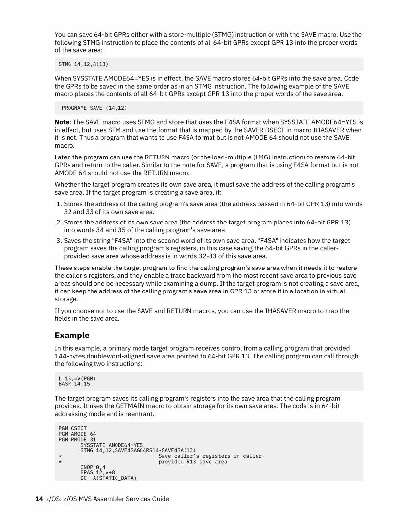
You can save 64-bit GPRs either with a store-multiple (STMG) instruction or with the SAVE macro. Use thefollowing STMG instruction to place the contents of all 64-bit GPRs except GPR 13 into the proper wordsof the save area:
STMG 14,12,8(13)
When SYSSTATE AMODE64=YES is in effect, the SAVE macro stores 64-bit GPRs into the save area. Codethe GPRs to be saved in the same order as in an STMG instruction. The following example of the SAVEmacro places the contents of all 64-bit GPRs except GPR 13 into the proper words of the save area.
PROGNAME SAVE (14,12)
Note: The SAVE macro uses STMG and store that uses the F4SA format when SYSSTATE AMODE64=YES isin effect, but uses STM and use the format that is mapped by the SAVER DSECT in macro IHASAVER whenit is not. Thus a program that wants to use F4SA format but is not AMODE 64 should not use the SAVEmacro.
Later, the program can use the RETURN macro (or the load-multiple (LMG) instruction) to restore 64-bitGPRs and return to the caller. Similar to the note for SAVE, a program that is using F4SA format but is notAMODE 64 should not use the RETURN macro.
Whether the target program creates its own save area, it must save the address of the calling program'ssave area. If the target program is creating a save area, it:
1. Stores the address of the calling program's save area (the address passed in 64-bit GPR 13) into words32 and 33 of its own save area.
2. Stores the address of its own save area (the address the target program places into 64-bit GPR 13)into words 34 and 35 of the calling program's save area.
3. Saves the string "F4SA" into the second word of its own save area. "F4SA" indicates how the targetprogram saves the calling program's registers, in this case saving the 64-bit GPRs in the caller-provided save area whose address is in words 32-33 of this save area.
These steps enable the target program to find the calling program's save area when it needs it to restorethe caller's registers, and they enable a trace backward from the most recent save area to previous saveareas should one be necessary while examining a dump. If the target program is not creating a save area,it can keep the address of the calling program's save area in GPR 13 or store it in a location in virtualstorage.
If you choose not to use the SAVE and RETURN macros, you can use the IHASAVER macro to map thefields in the save area.
ExampleIn this example, a primary mode target program receives control from a calling program that provided144-bytes doubleword-aligned save area pointed to 64-bit GPR 13. The calling program can call throughthe following two instructions:
L 15,=V(PGM)BASR 14,15
The target program saves its calling program's registers into the save area that the calling programprovides. It uses the GETMAIN macro to obtain storage for its own save area. The code is in 64-bitaddressing mode and is reentrant.
PGM CSECTPGM AMODE 64PGM RMODE 31 SYSSTATE AMODE64=YES STMG 14,12,SAVF4SAG64RS14-SAVF4SA(13) * Save caller's registers in caller-* provided R13 save area CNOP 0,4 BRAS 12,*+8 DC A(STATIC_DATA)
14 z/OS: z/OS MVS Assembler Services Guide

L 12,0(12,0) Set up to address of static data USING STATIC_DATA,12 GETMAIN RU,LV=144 Get my reentrant savearea STG 13,SAVF4SAPREV-SAVF4SA(,1) * Save caller's savearea address in my* savearea (backward chain) STG 1,SAVF4SANEXT-SAVF4SA(,13) * Save my savearea address in caller's* savearea (forward chain) MVC SAVF4SAID-SAVF4SA(4,1),=A(SAVF4SAID_VALUE)* Set ID into savearea to indicate how* caller's regs are saved LGR 13,1 Put my savearea address in R13* End of entry code. Begin program code here . . .⋮* Begin exit code LGR 1,13 Copy my savearea address LG 13,SAVF4SAPREV-SAVF4SA(,13) * Restore caller's savearea address FREEMAIN RU,A=(1),LV=144 Free my reentrant savearea SLR 15,15 Set return code of zero LG 14,SAVF4SAG64RS14-SAVF4SA(,13) * Restore caller's R14 LMG 2,12,SAVF4SAG64RS2-SAVF4SA(13) * Restore caller's R2-R12 BR 14 Return to caller⋮ STATIC_DATA DS 0D* Begin static data here IHASAVER END
If changing ARs without using the linkage stackAn AR mode program must specify SYSSTATE ASCENV=AR.
When a program that changes ARs and chooses not to use the linkage stack receives control, the targetprogram saves the GPRs and ARs into the 216-byte (or larger) doubleword-aligned caller-provided savearea pointed to by GPR 13 (and AR 13 when the caller is in AR mode). The format of this area is shown inFigure 5 on page 16. As indicated by this figure, the contents of each GPR, except GPR 13, must besaved in a specific location within the save area. GPR 13 is not saved into the save area; it holds theaddress of the save area. Similarly, the contents of each AR, except AR 13, must be saved in a specificlocation within the save area. AR 13 is not saved into the save area; it holds the ALET of the save area.
Chapter 2. Linkage conventions 15

WordContents
0Used by language products.
1Value of "F7SA". "F7SA", stored by a program in its save area, indicates how the program saves thecalling program's registers. Saving the 64-bit GPRs and the ARs in the caller-provided save areawhose address is in words 32-33 of this save area.
2 - 364-bit GPR 14 (return address).
4 - 564-bit GPR 15.
6 - 3164-bit GPRs 0 - 12.
32 - 33Address of previous save area (stored by a program in its save area).
34 - 35Address of next save area (stored by target program within caller's save area).
36 - 50ARs 14, 15, 0-12.
51ALET of previous save area.
52ASC mode of calling program.
53Undefined.
Figure 5. Format of the Format 7 save area (F7SA)
You can save 64-bit GPRs with a store-multiple (STMG) instruction. Use the following STMG instruction toplace the contents of all GPRs except GPR 13 into the proper words of the save area:
STMG 14,12,8(13)
You can save ARs with a store-access-register-multiple (STAM) instruction. Use the following STAMinstruction to place the contents of all AR into the proper words of the save area:
STAM 14,12,144(13)
Later, the program can use the LAM and LMG instructions to restore ARs and GPRs and return to the caller.
Whether the target program creates its own save area, it must save the address of the calling program'ssave area. If the target program creates a save area it:
1. Stores the 64-bit address of the calling program's save area (the address passed in 64-bit GPR 13) intowords 32 and 33 of its own save area.
2. Stores the ASC mode of the calling program into word 52 of its own save area.3. Stores the ALET of the calling program's save area (the value in AR 13) into word 51 of its own save
area4. Stores the address of its own save area (the address the target program places in GPR 13) into words
34 and 35 of the calling program's save area.
16 z/OS: z/OS MVS Assembler Services Guide

5. Saves the string "F7SA" into the second word of its own save area. "F7SA" indicates how the targetprogram saves the calling program's registers. Saving the 64-bit GPRs and the ARs in the caller-provided save area whose address is in words 32-33 of this save area.
These steps enable the target program to find the calling program's save area when it needs it to restorethe caller's registers, and they enable a trace backward from the most recent save area to a previous savearea if one is necessary while examining a dump. If the target program is not creating a save area, it cankeep the address of the calling program's save area in GPR 13 or store it in a location in virtual storage.
Use the IHASAVER macro to map the fields in the save area.
If your program is AR mode but the calling program is not known to be AR mode (it might be known to beprimary ASC mode or it might be either primary ASC or AR mode), you need to save the calling program'smode on entry and restore it on exit.
ExampleIn this example, an AR mode target program receives control from a calling program that provides a 216-byte doubleword-aligned save area pointed to by GPR 13.
The target program saves the calling program's registers (GPRs and ARs) into the save area that thecalling program provides. It uses the STORAGE OBTAIN macro to obtain storage for its own save area. Thecode is in 31-bit addressing mode and is reentrant.
PGM CSECTPGM AMODE 31PGM RMODE 31 SYSSTATE AMODE64=NO,ASCENV=AR STMG 14,12,SAVF7SAG64RS14-SAVF7SA(13) * Save caller's registers in caller-* provided R13 save area STAM 14,12,SAVF7SAAR14-SAVF7SA(13) Save caller's ARs IAC 2 Save caller's ASC mode SAC 512 Make sure we are in AR mode LARL 12,STATIC_DATA Set up to address of static data LAE 12,0(12,0) Make sure AR12 is 0 USING STATIC_DATA,12 STORAGE OBTAIN,LENGTH=216 Get my reentrant savearea STG 13,SAVF7SAPREV-SAVF7SA(,1) * Save caller's savearea address in my* savearea (backward chain) ST 2,SAVF7SAASC-SAVF7SA(,1) Save caller's ASC mode STAM 13,13,SAVF7SAAR13-SAVF7SA(1) Save caller's AR13 STG 1,SAVF7SANEXT-SAVF7SA(,13) * Save my savearea address in caller's* savearea (forward chain) MVC SAVF7SAID-SAVF7SA(4,1),=A(SAVF7SAID_VALUE)* Set ID into savearea to indicate how* caller's regs are saved
LAE 13,0(0,1) Put my savearea address/ALET in R13* End of entry code. Begin program code here . . .⋮* Begin exit code LGR 1,13 Copy my savearea address LAM 2,2,SAVF7SAAR13-SAVF7SA(13) Fetch caller's AR13 L 2,SAVF7SAASC-SAVF7SA(,13) Fetch caller's ASC mode LG 13,SAVF7SAPREV-SAVF7SA(,13) * Restore caller's savearea address STORAGE RELEASE,ADDR=(1),LENGTH=216 Free my savearea SLR 15,15 Set return code of zero SAC 0(2) Restore caller's ASC mode CPYA 13,2 Restore caller's AR13 LAM 14,12,SAVF7SAAR14-SAVF7SA(13) Restore caller's ARs LG 14,SAVF7SAG64RS14-SAVF7SA(,13) Restore caller's R14 LMG 2,12,SAVF7SAG64RS2-SAVF7SA(13) Restore caller's R2-R12 BR 14 Return to caller⋮ STATIC_DATA DS 0D* Begin static data here IHASAVER END
Chapter 2. Linkage conventions 17

Establishing a base registerEach program establishes a base register immediately after it saves the calling program's registers.Remember when you select a base register:
• Some instructions alter register contents (for example, TRT alters register 2). A list of instructions andtheir processing is available in Principles of Operation.
• Registers 13 - 1 are used during program linkage.• Register 12 is reserved for Language Environment (LE) use when writing an LE-conforming assembler
program. For more information see z/OS Language Environment Programming Guide.
Register 12 is generally a good choice for base register when not writing an LE-conforming assemblerprogram.
Your program should use the relative and immediate instruction set and thus not need codeaddressability in general. If the program is AMODE 64, this is expected. But the program does need toestablish addressability to any static data that it might need. The program might also need temporarycode addressability when invoking system macros. Macros such as STORAGE require the invoker to havecode addressability surround the macro invocation. Nevertheless, you should also help out systemmacros by identifying the architecture level under which your program is known to run. SYSSTATEARCHLVL=2 can be used for all programs that run only on supported z/OS releases.
When your program is entered in one AMODE and will change to another, be sure to set your baseregisters properly for the eventual AMODE. For example, suppose that your program is entered in AMODE31 and will switch to AMODE 64. If you use the LA or LARL instruction to set the base register while inAMODE 31, that will not clear bits 0-31 of the 64-bit register. All 64 bits must be set properly when beingused in AMODE 64. After the LA or LARL, you could use the LLGTR instruction to clear bits 0-32 of the 64-bit register.
Linkage procedures for primary mode programsA primary mode program can be called only by a program running in primary ASC mode. Thus an AR modeprogram must switch to primary ASC mode before calling a primary mode program.
The information summarizes the linkage procedures a primary mode program follows when it receivescontrol, when it returns control to a caller, and when it calls another program.
Primary mode programs receiving controlWhen a primary mode program receives control, it can save the calling program's registers on the linkagestack or in the caller-provided save area. If using the caller-provided save area, then distinctions aremade whether the primary mode program is or is not changing the 64-bit GPRs.
Note: The linkage conventions assume that a primary mode program does not use ARs. By leaving thecontents of the ARs untouched, the program preserves ARs 2 - 13 across program linkages.
Primary mode programs that use the linkage stackA primary mode program that uses the linkage stack must perform the following actions:
• Issue a BAKR instruction, which saves the caller's ARs and 64-bit GPRs on the linkage stack.• Establish a GPR as a base register.• Set GPR 13 to indicate that the caller's registers are saved on the linkage stack:
– If the program creates a save area, obtain a 72-byte save area on a word boundary (or 144 byte orlarger on a doubleword boundary if routines called by the program need that extra space) in theprimary address space:
1. Set the second word of the save area to the character string F1SA if obtaining a 72-byte save areaor F6SA if obtaining a 144 byte or larger save area
18 z/OS: z/OS MVS Assembler Services Guide

2. Load GPR 13 with the save area address.– If the program does not create a save area, do one of following actions:
- Load 0 into GPR 13.- Set the second word of a two-word area in the primary address space to the character string F1SA.
Load the address of the two-word area into GPR 13.
Primary mode programs that use the caller-provided save areaThe actions to be taken by a primary mode program that uses the caller-provided save area depend onthe following conditions:
• If the program does not change 64-bit GPRs and that uses the 72-byte caller-provided save area, theprogram must perform the following actions:
– Save 32-bit GPRs 0-12, 14, and 15 into the caller-provided save area pointed to by GPR 13.– Establish a base register.– Obtain a 72-byte save area on a word boundary (or 144 byte or larger on a doubleword boundary if
routines called by the program need that extra space) in the primary address space.– Store the address of the caller's save area into the back chain field of its own save area.– Store the address of its save area into the forward chain field of the caller's save area.
See “Example” on page 9.• If the program changes 64-bit GPRs and that uses the 72-byte caller-provided save area, the program
must perform the following actions:
– Save the low halves (bits 32 - 63) of GPRs 0-12, 14, and 15 into the caller-provided save area pointedto by GPR 13.
– Obtain a 216 byte (if using F5SA) or 288 byte (if using F8SA) save area on a doubleword boundary inthe primary address space
– Save the high halves (bits 0 - 31) of GPRs 0 - 15 into its own save area.– Store the address of the caller's save area into the back chain field of its own save area.– Store the address of its save area into the forward chain field of the caller's save area.– Set the word at offset 4 to F5SA or F8SA to indicate how the caller's registers were saved.
See “Example of F5SA” on page 11 and “Example of F8SA” on page 12.• If the program changes 64-bit GPRs and that uses the 144 byte caller-provided save area, the program
must perform the following actions:
– Save 64-bit GPRs 0-12, 14, and 15 into the caller-provided save area pointed to by GPR 13 in F4SAformat.
– Obtain a 144 byte save area on a doubleword boundary (or larger if routines called by the programneed that extra space) in the primary address space.
– Store the address of the caller's save area into the back chain field of its own save area.– Store the address of its save area into the forward chain field of the caller's save area.– Set the word at offset 4 to F4SA to indicate how the caller's registers were saved.
See “Example” on page 14.
Primary mode programs returning controlThe method that a primary mode program uses to return control to a caller depends on whether theprimary mode program used the linkage stack or the caller-provided save area.
A primary mode program that uses the linkage stack must:
Chapter 2. Linkage conventions 19

• Place return information (if any) for the caller into GPR 0, 1, or both. For information about passinginformation through a parameter list, see “Conventions for passing information through a parameterlist” on page 22.
• Load the return code, if any, into GPR 15.• Issue the PR instruction. The PR instruction restores the caller's ARs 2 - 14 and 64-bit GPRs 2-14 and
ASC mode from the linkage stack. The PR instruction removes the entry from the linkage stack, andreturns control to the caller.
A primary mode program that uses a caller-provided save area must:
• Place return information (if any) for the caller into GPR 0, 1, or both. For information about passinginformation through a parameter list, see “Conventions for passing information through a parameterlist” on page 22.
• Load GPR 13 with the address of the save area the calling program passes when making the call.• Load the return code, if any, into GPR 15.• Restore GPRs 2 - 12 and 14 from the caller's save area.• Return to the calling program.
Primary mode programs calling another programWhen a primary mode program calls another program, the calling program must:
• Place the address of its save area into GPR 13.• Load parameter information, if any, into GPR 0, GPR 1, or both.• Place the entry point address of the target program into GPR 15.• Call the target program.
Linkage procedures for AR mode programsAn AR mode program can be called by other AR mode programs or by primary mode programs. Theinformation summarizes the linkage procedures an AR mode program can follow when it receives control,when it returns control to a caller, and when it calls another program.
AR mode programs receiving control and using the linkage stackWhen an AR mode program receives control and uses the linkage stack, it would:
• Issue a BAKR instruction, which saves the caller's 64-bit GPRs and ARs on the linkage stack. (Althougha primary mode caller provides a save area, an AR mode target program would not use the area.
• Establish a GPR as a base register and load an ALET of 0 into the corresponding AR. (An ALET of 0causes the system to reference an address within the primary address space).
• Set GPR 13 to indicate that the caller's registers are saved on the linkage stack:
– If the program creates a save area, obtain a 72-byte save area on a word boundary (or 144 byte orlarger save area on a doubleword boundary if routines called by this program need it) in the primaryaddress space.
- Set the second word of the save area to the character string "F1SA" if obtaining a 72-byte save areaor "F6SA" if obtaining a 144 byte or larger save area
- Load GPR 13 with the save area address.- Set AR 13 to zero to indicate that the storage resides in the primary address space.
– If the program does not create a save area, do one of following actions:
- Load 0 into GPR 13.- Set the second word of a two word area in the primary address space to the character string
"F1SA". Load the address of the two word area into GPR 13.
20 z/OS: z/OS MVS Assembler Services Guide

AR mode programs returning control and using the linkage stackTo return control to the calling program after saving registers on the linkage stack, an AR mode programwould:
• Place return information, if any, for the caller into AR/GPR 0, AR/GPR 1, or both. For information aboutpassing information through a parameter list, see “Conventions for passing information through aparameter list” on page 22.
• Load the return code, if any, into GPR 15.• Issue the PR instruction. The PR instruction restores the caller's ARs 2-14 and 64-bit GPRs 2-14 and
ASC mode from the linkage stack, removes the entry from the linkage stack, and returns control to thecaller.
AR mode programs receiving control and not using the linkage stackWhen an AR mode program receives control, and does not want to use the linkage stack, its caller mustprovide an area large enough for the target program to save the 64-bit GPRs and the ARs into (at least 216bytes). The AR mode program would:
• Issue STMG to save the 64-bit GPRs into the caller-provided save area.• Issue STAM to save the ARs into the caller-provided area.• Establish a GPR as a base register and load an ALET of 0 into the corresponding AR. An ALET of 0 causes
the system to reference storage within the primary address space.• Issue IAC to save the current ASC mode.• Switch to a suitable ASC mode for continued processing.• Allocate a new save area.• Save the saved ASC mode and the calling program's AR13 into the new save area.• Store the address of the caller's save area into the back chain field of its own save area.• Store the address of its save area into the forward chain field of the caller's save area.• Save "F7SA" at offset 4 to indicate how the calling program's registers were saved.
See “Example” on page 17.
AR mode programs returning control and not using the linkage stackTo return control to the calling program, an AR mode program would:
• Place return information (if any) for the caller into AR/GPR 0, AR/GPR 1, or both. For information aboutpassing information through a parameter list, see “Conventions for passing information through aparameter list” on page 22.
• Load the return code, if any, into GPR 15.• Load the address of the calling program's save area from words 33-34 of the AR mode program's save
area into GPR 13.• Load the ALET of the calling program's save area from word 51 of the AR mode program's save area.• Load the ASC mode of the calling program from word 52 of the AR mode program's save area.• Restore the calling program's ASC mode.• Restore ARs 14-12 from the calling program's save area.• Restore GPR 14 and GPRs 0-12 from the calling program's save area.• Return to the caller by using the BR 14 or BSM, 0, 14 instruction according to your documentation
See “Example” on page 17.
Chapter 2. Linkage conventions 21

AR mode programs calling another programThe definition of an AR mode program, as stated in Chapter 2, “Linkage conventions,” on page 5, includesthe fact that such a program might switch from one ASC mode to another. Procedures for an AR modeprogram calls another program differ depending on whether the AR mode program is in primary ASCmode or AR mode at the time of the call.
To call while in AR mode, an AR mode program must:
• Load parameter information, if any, into AR/GPR 0, AR/GPR 1, or both. For information about passinginformation through a parameter list, see “Conventions for passing information through a parameterlist” on page 22.
• Place the entry point address of the target program into GPR 15. There is no need to load an ALET intoAR 15.
• Call the target program.
To call while in primary ASC mode, an AR mode program must follow the linkage conventions described in“Primary mode programs calling another program” on page 20.
Conventions for passing information through a parameter listThe ASC mode of a calling program at the time it calls determines whether addresses that the programpasses are ALET-qualified. The following two sections describe how programs in primary ASC mode andAR mode pass parameters through a parameter list.
Program in primary ASC modeIf the calling program is in primary ASC mode, the parameter list must be in the primary address space.All addresses that are passed by the programs must be contained in the primary address space and mustnot be ALET-qualified. The program that passes parameter data can use GPRs 0 and 1, or both. To passthe address of a parameter list, the program should use GPR 1.
As an example, consider the way that the system uses a register to pass information in the PARM field ofan EXEC statement to your program. When your program receives control from the system, register 1contains the address of a parameter list that points to one parameter. The parameter list is a fullword on afullword boundary in your program's address space see Figure 6 on page 22. The high-order bit (bit 0) ofthis word is set to 1. For a program that is not AMODE 64, the system uses this convention to indicate thelast word in a variable-length parameter list. Bits 1-31 of the fullword contain the address of a 2-bytelength field on a halfword boundary. The length field contains a binary count of the number of data bytesin the PARM field. The data bytes immediately follow the length field. If the PARM field was omitted in theEXEC statement, the count is set to zero. To prevent possible errors, always use the count as a lengthattribute in acquiring the information in the PARM field.
Figure 6. Primary Mode Parameter List EXEC PGM=
22 z/OS: z/OS MVS Assembler Services Guide

Note: The system builds a parameter list that matches the previous description even if the program is thetarget of an EXEC statement is AMODE 64. It is not a typical parameter list for an AMODE 64 program andthe AMODE 64 program must not use the address word without first clearing bit 0.
Unlike the parameter list produced for an EXEC statement, within a general parameter list:
• There can be multiple parameters.• There is no system-imposed limitation on the length of any parameter.• No parameter has a system-defined format.
Lengths and formats of parameters are defined by the called service. For an AMODE 24 or AMODE 31program, the parameter list consists of 4-byte wide address slots; for an AMODE 64 program, theparameter list consists of 8-byte wide address slots. For an AMODE 24 or AMODE 31 program, the high-order bit of the last address slot is used to indicate the end of the list. For an AMODE 64 program, thatconvention is not used. Instead, a separate parameter would be provided if the target program needs tobe able to determine how many parameters were passed. That separate parameter might be within theparameter list (for example, the first parameter list slot) or might be in register 0.
Programs in AR modeIf the calling program is in AR mode, all addresses that it passes, whether they are in a GPR or in aparameter list, must be ALET-qualified. A parameter list can be in an address space other than the callingprogram's primary address space or in a data space. It cannot be in the calling program's secondaryaddress space.
The Figure 7 on page 23 shows one way to format addresses and ALETs in a parameter list. Theaddresses passed to the called program are at the beginning of the list and their associated ALETs followthe addresses. Notice that the third address has the high-order bit set on to indicate the end of the list.For an AMODE 64 program, instead, the parameter list consists of 8-byte wide address slots (still followedby 4-byte wide ALET slots) and the high-order bit of the last address slot would not be used to indicatethe end of the list.
Figure 7. AR Mode Parameter List when Not AMODE 64
All addresses that an AR mode target program returns to an AR mode caller, whether the address is inGPR 0 or 1 or in a parameter list, must be ALET-qualified.
Chapter 2. Linkage conventions 23

24 z/OS: z/OS MVS Assembler Services Guide

Chapter 3. Subtask creation and control
The control program creates one task in the address space as a result of initiating execution of the jobstep task. You can create additional tasks in your program. However, if you do not, the job step task is theonly task in the address space being executed. The benefits of a multiprogramming environment are stillavailable even with only one task in the job step; work is still being performed for other address spaceswhen your task is waiting for an event, such as an input operation, to occur.
The advantage in creating additional tasks within the job step is that more tasks are competing forcontrol. When a wait state occurs in one of your tasks, it is not necessarily a task from some other addressspace that gets control. It can be one of your tasks, a portion of your job.
The general rule is that you should choose parallel execution of a job step (that is, more than one task inan address space) only when a significant amount of overlap between two or more tasks can be achieved.You must take into account the amount of time that is taken by the control program in establishing andcontrolling additional tasks, and your increased effort to coordinate the tasks and provide forcommunications between them.
Creating the taskA new task is created by issuing an ATTACH, or, if your program runs in access register ASC mode, anATTACHX macro. The task that is active when the ATTACH or ATTACHX issued is the originating task; thenewly created task is the subtask of the originating task. The subtask competes for control in the samemanner as any other task in the system, by priority (both address space priority and task priority withinthe address space) and the current ability to use a processor. The address of the task control block for thesubtask is returned in register 1.
If the ATTACH or ATTACHX executes successfully, control returns to the user with a return code of 0 inregister 15.
The entry point in the load module to be given control when the subtask becomes active is specified as itis in a LINK or LINKX macro, that is, by using the EP, EPLOC, and DE parameters. The use of theseparameters is discussed in Chapter 4, “Program management,” on page 29. You can pass parameters tothe subtask using the PARAM and VL parameters, also described under the LINK macro. Additionalparameters deal with the priority of the subtask, provide for communication between tasks, specifylibraries to be used for program linkages, and establish an error recovery environment for the newsubtask.
PrioritiesThis information considers three priorities: address space priorities, task priorities, and subtask priorities.
Address space priorityWhen a job is initiated, the control program creates an address space. All successive steps in the jobexecute in the same address space. The address space has a dispatching priority, which is normallydetermined by the control program. The control program selects, and alters, the priority to achieve thebest load balance in the system. This makes the most efficient use of processor time and other systemresources.
You might want some jobs to execute at a different address space priority than the default priorityassigned. The active workload management (WLM) service policy determines the dispatching priorityassigned to the job. For additional information, see z/OS MVS Planning: Workload Management.
© Copyright IBM Corp. 1988, 2020 25

Task priorityEach task in an address space has a limit priority and a dispatching priority associated with it. The controlprogram sets these priorities when a job step is initiated. When you use the ATTACH or ATTACHX macro tocreate other tasks in the address space, you can use the LPMOD and DPMOD parameters to give themdifferent limit and dispatching priorities.
The dispatching priorities of the tasks in an address space do not affect the order in which the controlprogram selects jobs for execution. The order is selected based on the work unit (WEB) that is at the topof the work unit queue (WUQ). The dispatcher no longer selects from within an address space the toppriority task awaiting execution. Thus, task priorities cannot affect processing within an address space.
Note: In a multiprocessing system, task priorities might not be in the order of which the tasks run. Morethan one task might be running simultaneously in the same address space on different processors. Pagefaults can alter the order in which the tasks run.
Subtask priorityWhen a subtask is created, the limit and dispatching priorities of the subtask are the same as the currentlimit and dispatching priorities of the originating task except when the subtask priorities are modified bythe LPMOD and DPMOD parameters of the ATTACH and ATTACHX macro. The LPMOD parameter specifiesthe signed number to be subtracted from the current limit priority of the originating task. The result of thesubtraction is assigned as the limit priority of the subtask. If the result is zero or negative, zero is assignedas the limit priority. The DPMOD parameter specifies the signed number to be added to the currentdispatching priority of the originating task. The result of the addition is assigned as the dispatching priorityof the subtask, unless the number is greater than the limit priority or less than zero. In that case, the limitpriority or 0, respectively, is used as the dispatching priority.
Assigning and changing priorityAssign tasks with many I/O operations a higher priority than tasks with little I/O because the tasks withmuch I/O are in a wait state for a greater amount of time. The lower priority tasks are executed when thehigher priority tasks are in a wait state. As the I/O operations are completed, the higher priority tasks getcontrol so that more I/O can be started.
You can change the priorities of subtasks by using the CHAP macro. The CHAP macro changes thedispatching priority of the active task or one of its subtasks by adding a positive or negative value. Thedispatching priority of an active task can be made less than the dispatching priority of another task. If thisoccurs and the other task is dispatchable, it would be given control after execution of the CHAP macro.
You can also use the CHAP macro to increase the limit priority of any of an active task's subtasks. Anactive task cannot change its own limit priority. The dispatching priority of a subtask can be raised aboveits own limit priority, but not above the limit of the originating task. When the dispatching priority of asubtask is raised above its own limit priority, the subtask's limit priority is automatically raised to equal itsnew dispatching priority.
Stopping and restarting a subtask (STATUS macro)To stop a subtask means to change its dispatch-ability status from ready to not ready. You might need tostop a subtask that is ready or running, and then to restart, or make ready, that subtask. Stopping asubtask is a programming technique to control the dispatch-ability of other related tasks or subtasks in amultitasking environment when the tasks are in problem state.
To stop all subtasks of an originating task, issue the STATUS macro with the STOP parameter. To stop aspecific subtask, issue the STATUS macro with the STOP, TCB parameter, which identifies a specificsubtask.
To restart the stopped subtask or subtasks, issue STATUS START. As with STATUS STOP, use the TCBparameter to restart a specific subtask.
26 z/OS: z/OS MVS Assembler Services Guide

Task and subtask communicationsThe task management information is required only for establishing communications among tasks in thesame job step. The relationship of tasks in a job step is shown in Figure 8 on page 27. The horizontallines in Figure 8 on page 27 separate originating tasks and subtasks. They have no bearing on taskpriority. Tasks A, A1, A2, A2a, B, B1, and B1a are all subtasks of the job-step task; tasks A1, A2, and A2aare subtasks of task A. Tasks A2a and B1a are the lowest level tasks in the job step. Although task B1 is atthe same level as tasks A1 and A2, it is not considered a subtask of task A.
Task A is the originating task for both tasks A1 and A2, and task A2 is the originating task for task A2a. Ahierarchy of tasks exists within the job step. Therefore, the job step task, task A, and task A2 arepredecessors of task A2a, while task B has no direct relationship to task A2a.
Figure 8. Levels of Tasks in a Job Step
All of the tasks in the job step compete independently for processor time; if no constraints are provided,the tasks are performed and are terminated asynchronously. However, since each task is performing aportion of the same job step, some communication and constraints between tasks are required, such asnotifying each other when a subtask completes. If a predecessor task attempts to terminate before all ofits subtasks are complete, those subtasks and the predecessor task are abnormally terminated.
Two parameters, the ECB and ETXR parameters, are provided in the ATTACH or ATTACHX macro to helpcommunication between a subtask and the originating task. These parameters are used to indicate thenormal or abnormal termination of a subtask to the originating task. If you coded the ECB or ETXRparameter, or both, in the ATTACH or ATTACHX macro, the task control block of the subtask is notremoved from the system when the subtask is terminated. The originating task must remove the taskcontrol block from the system after termination of the subtask by issuing a DETACH. If you specified theECB parameter in the ATTACH or ATTACHX macro, the ECB must be in storage addressable by the
Chapter 3. Subtask creation and control 27

attaching task and control program so that the issuer of ATTACH can wait on it (using the WAIT macro)and the control program can post it on behalf of the terminating task. The task control blocks for allsubtasks must be removed before the originating task can terminate normally.
The ETXR parameter specifies the address of an end-of-task exit routine in the originating task, which isto be given control when the subtask being created is terminated. Therefore, the end-of-task routine isgiven control asynchronously after the subtask has terminated and must be in virtual storage when it isrequired. After the control program terminates the subtask, the end-of-task routine that is specified isscheduled to be executed. It competes for CPU time using the priority of the originating task and of itsaddress space and can receive control even though the originating task is in the wait state. Although theDETACH does not have to be issued in the end-of-task routine, this is a good place for it.
The ECB parameter specifies the address of an event control block (discussed under "TaskSynchronization"), which is posted by the control program when the subtask is terminated. After postingoccurs, the event control block contains the completion code specified for the subtask.
If you specified not the ECB or the ETXR parameter in the ATTACH or ATTACHX macro, the task controlblock for the subtask is removed from the system when the subtask terminates. Its originating task doesnot have to issue a DETACH. A reference to the task control block in a CHAP or a DETACH macro in thiscase is as risky as task termination. Since the originating task is not notified of subtask termination, youcan refer to a task control block that is removed from the system, which would cause the active task to beabnormally terminated.
Note: The originating task is abended if it attempts to normally terminate when it has active subtasks.
28 z/OS: z/OS MVS Assembler Services Guide

Chapter 4. Program management
This chapter discusses facilities that will help you to design your programs. It includes descriptions of theresidency mode and addressing mode of programs, linkage considerations, load module structures,facilities for passing control between programs, and the use of the associated macro.
Residency and addressing mode of programsThe control program ensures that each load module is loaded above or below 16 megabytes virtual asappropriate and that it is invoked in the correct addressing mode (24-bit or 31-bit). The placement of themodule above or below 16 megabytes depends on the residency mode (RMODE) that you define for themodule. Whether a module executes in 24-bit or 31-bit addressing mode depends on the addressingmode (AMODE) that you define for the module.
When a program is executing in 24-bit addressing mode, the system treats both instruction and dataaddresses as 24-bit addresses. This allows programs executing in 24-bit addressing mode to address 16megabytes (16,777,216 bytes) of storage. Similarly, when a program is executing in 31-bit addressingmode, the system treats both instruction and data addresses as 31-bit addresses. This allows a programexecuting in 31-bit addressing mode to address 2 gigabytes (2,147,483,648 bytes or 128 x 16megabytes) of storage.
You can define the residency mode and the addressing mode of a program in the source code. Figure 9 onpage 29 shows an example of the definition of the AMODE and RMODE attributes in the source code.This example defines the addressing mode of the load module as 31-bit and the residency mode of theload module as 24-bit. Therefore, the program will receive control in 31-bit addressing mode and willreside below 16 megabytes.
SAMPLE CSECTSAMPLE AMODE 31SAMPLE RMODE 24
Figure 9. Assembler Definition of AMODE/RMODE
The assembler places the AMODE and RMODE in the external symbol dictionary (ESD) of the output objectmodule for use by the linkage editor. The linkage editor passes this information on to the control programthrough the directory entry for the partitioned data set (PDS) that contains the load module and thecomposite external symbol dictionary (CESD) record in the load module. You can also specify the AMODE/RMODE attributes of a load module by using linkage editor control cards. Chapter 5, “Understanding 31-bit addressing,” on page 59 contains additional information about residency and addressing mode; z/OSMVS Program Management: User's Guide and Reference and z/OS MVS Program Management: AdvancedFacilities contain information about the linkage editor control cards.
Residency mode definitionsThe control program uses the RMODE attribute from the PDS directory entry for the module to load theprogram above or below 16 megabytes. The RMODE attribute can have one of the following values: 24
specifies that the program must reside in 24-bit addressable virtual storage.ANY
specifies that the program can reside anywhere in virtual storage because the code has no virtualstorage residency restrictions.
Note: The default value for RMODE is 24.
© Copyright IBM Corp. 1988, 2020 29

Addressing mode definitionsThe AMODE attribute, located in the PDS directory entry for the module, specifies the addressing modethat the module expects at entry. Bit 32 of the program status word (PSW) indicates the addressing modeof the program that is executing. The system supports programs that execute in either 24-bit or 31-bitaddressing mode. The AMODE attribute can have one of the following values:24
specifies that the program is to receive control in 24-bit addressing mode.31
specifies that the program is to receive control in 31-bit addressing mode.ANY
specifies that the program is to receive control in either 24-bit or 31-bit addressing mode.
Note: The default value for AMODE is 24.
Linkage considerationsThe system supports programs that execute in either 24-bit or 31-bit addressing mode. The followingbranch instructions take addressing mode into consideration:
• Branch and link (BAL)• Branch and link, register form (BALR)• Branch and save (BAS)• Branch and save, register form (BASR)• Branch and set mode (BSM)• Branch and save and set mode (BASSM)• Branch and stack (BAKR)
See Principles of Operation for a complete description of how these instructions function. The followingparagraphs provide a general description of these branch instructions.
The BAL and BALR instructions are unconditional branch instructions (to the address in operand 2). BALand BALR function differently depending on the addressing mode in which you are executing. Thedifference is in the linkage information passed in the link register when these instructions execute. In 31-bit addressing mode, the link register contains the AMODE indicator (bit 0) and the address of the nextsequential instruction (bits 1-31); in 24-bit addressing mode, the link register contains the instructionlength code, condition code, program mask, and the address of the next sequential instruction.
BAS and BASR perform the same function that BAL and BALR perform when BAL and BALR execute in 31-bit addressing mode.
The BSM instruction provides problem programs with a way to change the AMODE bit in the PSW. BSM isan unconditional branch instruction (to the address in operand 2) that saves the current AMODE in thehigh-order bit of the link register (operand 1), and sets the AMODE indicator in the PSW to agree with theAMODE of the address to which you are transferring control (that is, the high order bit of operand 2).
The BASSM instruction functions in a manner similar to the BSM instruction. In addition to saving thecurrent AMODE in the link register, setting the PSW AMODE bit, and transferring control, BASSM alsosaves the address of the next sequential instruction in the link register thereby providing a return address.
BASSM and BSM are used for entry and return linkage in a manner similar to BALR and BR. The majordifference from BALR and BR is that BASSM and BSM can save and change addressing mode.
The BAKR instruction is an unconditional branch to the address in operand 2. In addition to the branchingaction, it adds an entry to the linkage stack.
For more information on the linkage stack, see “System-provided linkage stack” on page 7.
30 z/OS: z/OS MVS Assembler Services Guide

Floating point considerationsThe application program and run-time environment are responsible for managing the contents of theFloating Point Control (FPC) register. The system will normally not change the FPC register settings of anexisting MVS task or SRB.
The S/390® linkage convention for the Floating Point Registers and the FPC register in described inChapter 2, “Linkage conventions,” on page 5. To summarize the convention, FPRs 0 to 7 are volatile andFPRs 8 to 15 are non-volatile across a call. The FPC register is non-volatile except for two fields: the IEEEexception flags and the DXC, which are volatile.
Passing control between programs with the same AMODEIf you are passing control between programs that execute in the same addressing mode, there are severalcombinations of instructions that you can use. Some of these combinations are:Transfer
ReturnBAL/BALR
BRBAS/BASR
BR
Passing control between programs with different AMODEsIf you are passing control between programs executing in different addressing modes, you must changethe AMODE indicator in the PSW. The BASSM and BSM instructions perform this function for you. You cantransfer to a program in another AMODE using a BASSM instruction and then return by means of a BSMinstruction. This sequence of instructions ensures that both programs execute in the correct AMODE.
Figure 10 on page 32 shows an example of passing control between programs with different addressingmodes. In the example, TEST executes in 24-bit AMODE and EP1 executes in 31-bit AMODE. Beforetransferring control to EP1, the TEST program loads register 15 with EPA, the pointer defined entry pointaddress (that is, the address of EP1 with the high order bit set to 1 to indicate 31-bit AMODE). This isfollowed by a BASSM 14,15 instruction, which performs the following functions:
• Sets the high-order bit of the link register (register 14) to 0 (because TEST is currently executing in 24-bit AMODE) and puts the address of the next sequential instruction into bits 1-31.
• Sets the PSW AMODE bit to 1 to agree with bit 0 of register 15.• Transfers to EP1 (the address in bits 1-31 of register 15).
The EP1 program executes in 31-bit AMODE. Upon completion, EP1 sets a return code in register 15 andexecutes a BSM 0,14 instruction, which performs the following functions:
• Sets the PSW AMODE bit to 0 to correspond to the high-order bit of register 14.• Transfers control to the address following the BASSM instruction in the TEST program.
Chapter 4. Program management 31
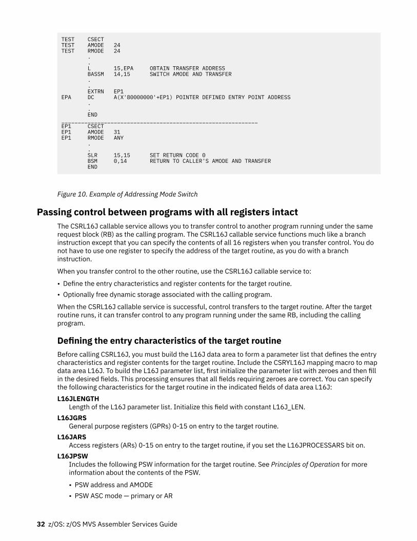
TEST CSECTTEST AMODE 24TEST RMODE 24 . . L 15,EPA OBTAIN TRANSFER ADDRESS BASSM 14,15 SWITCH AMODE AND TRANSFER . . EXTRN EP1EPA DC A(X'80000000'+EP1) POINTER DEFINED ENTRY POINT ADDRESS . . END____________________________________________________________EP1 CSECTEP1 AMODE 31EP1 RMODE ANY . . SLR 15,15 SET RETURN CODE 0 BSM 0,14 RETURN TO CALLER'S AMODE AND TRANSFER END
Figure 10. Example of Addressing Mode Switch
Passing control between programs with all registers intactThe CSRL16J callable service allows you to transfer control to another program running under the samerequest block (RB) as the calling program. The CSRL16J callable service functions much like a branchinstruction except that you can specify the contents of all 16 registers when you transfer control. You donot have to use one register to specify the address of the target routine, as you do with a branchinstruction.
When you transfer control to the other routine, use the CSRL16J callable service to:
• Define the entry characteristics and register contents for the target routine.• Optionally free dynamic storage associated with the calling program.
When the CSRL16J callable service is successful, control transfers to the target routine. After the targetroutine runs, it can transfer control to any program running under the same RB, including the callingprogram.
Defining the entry characteristics of the target routineBefore calling CSRL16J, you must build the L16J data area to form a parameter list that defines the entrycharacteristics and register contents for the target routine. Include the CSRYL16J mapping macro to mapdata area L16J. To build the L16J parameter list, first initialize the parameter list with zeroes and then fillin the desired fields. This processing ensures that all fields requiring zeroes are correct. You can specifythe following characteristics for the target routine in the indicated fields of data area L16J:L16JLENGTH
Length of the L16J parameter list. Initialize this field with constant L16J_LEN.L16JGRS
General purpose registers (GPRs) 0-15 on entry to the target routine.L16JARS
Access registers (ARs) 0-15 on entry to the target routine, if you set the L16JPROCESSARS bit on.L16JPSW
Includes the following PSW information for the target routine. See Principles of Operation for moreinformation about the contents of the PSW.
• PSW address and AMODE• PSW ASC mode — primary or AR
32 z/OS: z/OS MVS Assembler Services Guide

• PSW program mask• PSW condition code
APF-authorized callers, callers in supervisor state, PSW key 0-7, or PKM allowing key 0-7, can specify:
• PSW state - problem or supervisor• PSW key.
For unauthorized callers, the PSW state and key of the calling program are used for the target routine.
L16JPROCESSARSA bit indicating whether or not you want to specify the contents of the access registers (ARs) for thetarget routine. Set the bit on if you want to specify the contents of the ARs. If you set the bit off, theaccess registers (ARs) contents are determined by the system.
When CSRL16J passes control to the target routine, the GPRs contain:Register
Contents0-15
Values specified by the caller
If the L16JPROCESSARS bit is set on, when CSRL16J passes control to the target routine the accessregisters (ARs) contain:Register
Contents0-15
Values specified by the caller
If the L16JPROCESSARS bit is set off, when CSRL16J passes control to the target routine the accessregisters (ARs) contain:Register
Contents0-1
Do not contain any information for use by the routine2-13
The contents are the same as they were when the caller issued the CSRL16J callable service.14-15
Do not contain any information for use by the routine
Freeing dynamic storage associated with the callerIf the calling program has a dynamic storage area associated with it, you can specify that CSRL16J freesome or all of this storage area before it transfers control to the target routine. In the L16J parameter list,specify the following fields:L16JSUBPOOL
Specify the subpool of the area that you want the system to free.L16JLENGTHTOFREE
Specify the length, in bytes, of the dynamic storage area you want the system to free.L16JAREATOFREE
Specify the address of the dynamic storage area you want the system to free.
Make sure that the address is on a doubleword boundary. Otherwise, the service ends with an abendcode X'978'. See z/OS MVS System Codes for information on abend code X'978'.
The system frees the storage only when the CSRL16J callable service is successful.
Chapter 4. Program management 33

Load module structure typesEach load module used during a job step can be designed in one of three load module structures: simple,planned overlay, or dynamic. A simple structure does not pass control to any other load modules duringits execution, and comes into virtual storage all at one time. A planned overlay structure may, if necessary,pass control to other load modules during its execution, and it does not come into virtual storage all atone time. Instead, segments of the load module reuse the same area of virtual storage. A dynamicstructure comes into virtual storage all at one time, and passes control to other load modules during itsexecution. Each of the load modules to which control is passed can be one of the three structure types.Characteristics of the load module structure types are summarized in Table 1 on page 34.
Because the large capacity of virtual storage eliminates the need for complex overlay structures, plannedoverlays will not be discussed further.
Table 1. Characteristics of Load Modules
Structure Type Loaded All at One Time Passes Control to Other Load Modules
Simple Yes No
Planned Overlay No Optional
Dynamic Yes Yes
Simple structureA simple structure consists of a single load module produced by the linkage editor. The single loadmodule contains all of the instructions required and is paged into central storage by the control programas it is executed. The simple structure can be the most efficient of the two structure types because theinstructions it uses to pass control do not require control-program assistance. However, you shoulddesign your program to make most efficient use of paging.
Dynamic structureA dynamic structure requires more than one load module during execution. Each required load modulecan operate as either a simple structure or another dynamic structure. The advantages of a dynamicstructure over a simple structure increase as the program becomes more complex, particularly when thelogical path of the program depends on the data being processed. The load modules required in adynamic structure are paged into central storage when required, and can be deleted from virtual storagewhen their use is completed.
Load module executionDepending on the configuration of the operating system and the macros used to pass control, execution ofthe load modules is serial or in parallel. Execution is serial in the operating system unless you use anATTACH or ATTACHX macro to create a new task. The new task competes for processor timeindependently with all other tasks in the system. The load module named in the ATTACH or ATTACHXmacro is executed in parallel with the load module containing the ATTACH or ATTACHX macro. Theexecution of the load modules is serial within each task.
The following paragraphs discuss passing control for serial execution of a load module. For information oncreating and managing new tasks, see “Creating the task” on page 25.
Passing control in a simple structureThere are certain procedures to follow when passing control to an entry point in the same load module.The established conventions to use when passing control are also discussed. These procedures andconventions are the framework for all program interfaces.
34 z/OS: z/OS MVS Assembler Services Guide

Passing control without returnSome control sections pass control to another control section of the load module and do not receivecontrol back. An example of this type of control section is a housekeeping routine at the beginning of aprogram that establishes values, initializes switches, and acquires buffers for the other control sections inthe program. Use the following procedures when passing control without return.
Preparing to pass control• Restore the contents of register 14.
Because control will not be returned to this control section, you must restore the contents of register14. Register 14 originally contained the address of the location in the calling program (for example, thecontrol program) to which control is to be passed when your program is finished. Since the currentcontrol section does not make the return to the calling program, the return address must be passed onto the control section that does make the return.
• Restore the contents of registers 2-12.
In addition, the contents of registers 2-12 must be unchanged when your program eventually returnscontrol, so you must also restore these registers.
If control were being passed to the next entry point from the control program, register 15 would containthe entry address. You should use register 15 in the same way, so that the called routine remainsindependent of the program that passed control to it.
• Use register 1 to pass parameters.
Establish a parameter list and place the address of the list in register 1. The parameter list shouldconsist of consecutive fullwords starting on a fullword boundary, each fullword containing an address tobe passed to the called control section. When executing in 24-bit AMODE, each address is located in thethree low-order bytes of the word. When executing in 31-bit AMODE, each address is located in bits1-31 the word. In both addressing modes, set the high-order bit of the last word to 1 to indicate that itis the last word of the list. The system convention is that the list contain addresses only. You may, ofcourse, deviate from this convention; however, when you deviate from any system convention, yourestrict the use of your programs to those programmers who know about your special conventions.
• Pass the address of the save area in register 13 just as it was passed to you.
Since you have reloaded all the necessary registers, the save area that you received on entry is nowavailable, and should be reused by the called control section. By passing the address of the old savearea, you save the 72 bytes of virtual storage for a second, unnecessary, save area.
Note: If you pass a new save area instead of the one received on entry, errors could occur.
Passing control• Load register 15 with a V-type address constant for the name of the external entry point, then branch to
the address in register 15.
This is the common way to pass control between one control section and an entry point in the sameload module. The external entry point must have been identified using an ENTRY instruction in thecalled control section if the entry point is not the same as the control section's CSECT name.
Figure 11 on page 36 shows an example of loading registers and passing control. In this example, nonew save area is used, so register 13 still contains the address of the old save area. It is also assumed forthis example that the control section will pass the same parameters it received to the next entry point.First, register 14 is reloaded with the return address. Next, register 15 is loaded with the address of theexternal entry point NEXT, using the V-type address constant at the location NEXTADDR. Registers 0-12are reloaded, and control is passed by a branch instruction using register 15. The control section to whichcontrol is passed contains an ENTRY instruction identifying the entry point NEXT.
Chapter 4. Program management 35

. . L 14,12(13) LOAD CALLER'S RETURN ADDRESS L 15,NEXTADDR ENTRY NEXT LM 0,12,20(13) RETURN CALLER's REGISTERS BR 15 NEXT SAVE (14,12) . .NEXTADDR DC V(NEXT)
Figure 11. Passing Control in a Simple Structure
Figure 12 on page 36 shows an example of passing a parameter list to an entry point with the sameaddressing mode. Early in the routine the contents of register 1 (that is, the address of the fullwordcontaining the PARM field address) were stored at the fullword PARMADDR. Register 13 is loaded with theaddress of the old save area, which had been saved in word 2 of the new save area. The contents ofregister 14 are restored, and register 15 is loaded with the entry address.
. . USING *,12 Establish addressabilityEARLY ST 1,PARMADDR Save parameter address . . L 13,4(13) Reload address of old save area L 0,20(13) L 14,12(13) Load return address L 15,NEXTADDR Load address of next entry point LA 1,PARMLIST Load address of parameter list OI PARMADDR,X'80' Turn on last parameter indicator LM 2,12,28(13) Reload remaining registers BR 15 Pass control . .PARMLIST DS 0ADCBADDRS DC A(INDCB) DC A(OUTDCB)PARMADDR DC A(0)NEXTADDR DC V(NEXT)
Figure 12. Passing Control With a Parameter List
The address of the list of parameters is loaded into register 1. These parameters include the addresses oftwo data control blocks (DCBs) and the original register 1 contents. The high-order bit in the last addressparameter (PARMADDR) is set to 1 using an OR-immediate instruction. The contents of registers 2-12 arerestored. (Since one of these registers was the base register, restoring the registers earlier would havemade the parameter list unaddressable.) A branch register instruction using register 15 passes control toentry point NEXT.
Passing control with returnThe control program passed control to your program, and your program will return control when it isthrough processing. Similarly, control sections within your program will pass control to other controlsections, and expect to receive control back. An example of this type of control section is a monitoringroutine; the monitor determines the order of execution of other control sections based on the type ofinput data. Use the following procedures when passing control with return.
Preparing to pass control• Use registers 15 and 1 in the same manner they are used to pass control without return.
Register 15 contains the entry address in the new control section and register 1 is used to pass aparameter list.
• Ensure that register 14 contains the address of the location to which control is to be returned when thecalled control section completes execution.
36 z/OS: z/OS MVS Assembler Services Guide

The address can be the instruction following the instruction which causes control to pass, or it can beanother location within the current control section designed to handle all returns.
Registers 2-12 are not involved in the passing of control; the called control section should not dependon the contents of these registers in any way.
• Provide a new save area for use by the called control section as previously described, and pass theaddress of that save area in register 13.
Note that the same save area can be reused after control is returned by the called control section. Onenew save area is ordinarily all you will require regardless of the number of control sections called.
Passing controlYou may use two standard methods for passing control to another control section and providing for returnof control. One is an extension of the method used to pass control without a return, and requires a V-typeaddress constant and a branch, a branch and link, or a branch and save instruction provided bothprograms execute in the same addressing mode. If the addressing mode changes, use a branch and saveand set mode instruction. The other method uses the CALL macro to provide a parameter list andestablish the entry and return addresses. With either method, you must identify the entry point by anENTRY instruction in the called control section if the entry name is not the same as the control sectionCSECT name. Figure 13 on page 37 and Figure 14 on page 38 illustrate the two methods of passingcontrol; in each example, assume that register 13 already contains the address of a new save area.
Figure 13 on page 37 also shows the use of an inline parameter list and an answer area. The address ofthe external entry point is loaded into register 15 in the usual manner. A branch and link instruction isthen used to branch around the parameter list and to load register 1 with the address of the parameterlist. An inline parameter list, such as the one shown in Figure 13 on page 37, is convenient when you aredebugging because the parameters involved are located in the listing (or the dump) at the point they areused, instead of at the end of the listing or dump. Note that the high-order bit of the last addressparameter (ANSWERAD) is set to 1 to indicate the end of the list. The area pointed to by the address in theANSWERAD parameter is an area to be used by the called control section to pass parameters back to thecalling control section. This is a possible method to use when a called control section must passparameters back to the calling control section. Parameters are passed back in this manner so that noadditional registers are involved. The area used in this example is twelve words. The size of the area forany specific application depends on the requirements of the two control sections involved.
. . L 15,NEXTADDR Entry address in register 15 CNOP 0,4 BAL 1,GOOUT Parameter list address in register 1PARMLIST DS 0A Start of parameter listDCBADDRS DC A(INDCB) Input DCB address DC A(OUTDCB) Output DCB addressANSWERAD DC A(AREA+X'80000000') Answer area address with high-order bit onNEXTADDR DC V(NEXT) Address of entry pointGOOUT BALR 14,15 Pass control; register 14 contains return address and current AMODERETURNPT ...AREA DC 12F'0' Answer area from NEXT
Note: This example assumes that you are passing control to a program that executes in the sameaddressing mode as your program. See “Linkage considerations” on page 30 for information on how tohandle branches between programs that execute in different addressing modes.
Figure 13. Passing Control With Return
Chapter 4. Program management 37

CALL NEXT,(INDCB,OUTDCB,AREA),VLRETURNPT ...AREA DC 12F'0'
Note: If you are using the CALL macro to pass control to a program that executes in a different addressingmode, you must include the LINKINST=BASSM parameter.
Figure 14. Passing Control With CALL
The CALL macro in Figure 14 on page 38 provides the same functions as the instructions in Figure 13 onpage 37. When the CALL macro is expanded, the parameters cause the following results:
• NEXT - A V-type address constant is created for NEXT, and the address is loaded into register 15.• (INDCB,OUTDCB,AREA) - A-type address constants are created for the three parameters coded within
parentheses, and the address of the first A-type address constant is placed in register 1.• VL - The high-order bit of the last A-type address constant is set to 1.
Control is passed to NEXT using a branch and link instruction. (Optionally, you can specify either a BASRor BASSM instruction, with the LINKINST= parameter.) The address of the instruction following the CALLmacro is loaded into register 14 before control is passed.
In addition to the results described earlier, the V-type address constant generated by the CALL macrorequires the load module with the entry point NEXT to be link edited into the same load module as thecontrol section containing the CALL macro. The z/OS MVS Program Management: User's Guide andReference and z/OS MVS Program Management: Advanced Facilitiespublications tell more about thisservice.
The parameter list constructed from the CALL macro in Figure 14 on page 38, contains only A-typeaddress constants. A variation on this type of parameter list results from the following coding:
CALL NEXT,(INDCB,(6),(7)),VL
In the preceding CALL macro, two of the parameters to be passed are coded as registers rather thansymbolic addresses. The expansion of this macro again results in a three-word parameter list; in thisexample, however, the expansion also contains instructions that store the contents of registers 6 and 7 inthe second and third words, respectively, of the parameter list. The high-order bit in the third word is setto 1 after register 7 is stored. You can specify as many address parameters as you need, and you can usesymbolic addresses or register contents as you see fit.
Analyzing the returnWhen the control program returns control to a caller after it invokes a system service, the contents ofregisters 2-13 are unchanged. When control is returned to your control section from the called controlsection, registers 2-14 contain the same information they contained when control was passed, as long assystem conventions are followed. The called control section has no obligation to restore registers 0 and 1;so the contents of these registers may or may not have been changed.
When control is returned, register 15 can contain a return code indicating the results of the processingdone by the called control section. If used, the return code should be a multiple of four, so a branchingtable can be used easily, and a return code of zero should be used to indicate a normal return. The controlprogram frequently uses this method to indicate the results of the requests you make using systemmacros; an example of the type of return codes the control program provides is shown in the descriptionof the IDENTIFY macro.
The meaning of each of the codes to be returned must be agreed upon in advance. In some cases, either a“good” or “bad” indication (zero or nonzero) will be sufficient for you to decide your next action. If this istrue, the coding in Figure 15 on page 39 could be used to analyze the results. Many times, however, theresults and the alternatives are more complicated, and a branching table, such as shown in Figure 16 onpage 39 could be used to pass control to the proper routine.
Note: Explicit tests are required to ensure that the return code value does not exceed the branch tablesize.
38 z/OS: z/OS MVS Assembler Services Guide

RETURNPT LTR 15,15 Test return code for zero BNZ ERRORTN Branch if not zero to error routine . .
Figure 15. Test for Normal Return
RETURNPT B RETTAB(15) Branch to table using return codeRETTAB B NORMAL Branch to normal routine B COND1 Branch to routine for condition 1 B COND2 Branch to routine for condition 2 B GIVEUP Branch to routine to handle impossible situations. . .
Figure 16. Return Code Test Using Branching Table
How control is returnedIn the discussion of the return under “Analyzing the return” on page 38, it was indicated that the controlsection returning control must restore the contents of registers 2-14. Because these are the sameregisters reloaded when control is passed without a return, refer to the discussion under “Passing Controlwithout Return” for detailed information and examples. The contents of registers 0 and 1 do not have tobe restored.
Register 15 can contain a return code when control is returned. As indicated previously, a return codeshould be a multiple of four with a return code of zero indicating a normal return. The return codes otherthan zero that you use can have any meaning, as long as the control section receiving the return codes isaware of that meaning.
The return address is the address originally passed in register 14; you should always return control to thataddress. If an addressing mode switch is not involved, you can either use a branch instruction such as BR14, or you can use the RETURN macro. An example of each of these methods of returning control isdiscussed in the following paragraphs. If an addressing mode switch is involved, you can use a BSM 0,14instruction to return control. See Figure 10 on page 32 for an example that uses the BSM instruction toreturn control.
Figure 17 on page 39 shows a portion of a control section used to analyze input data cards and to checkfor an out-of-tolerance condition. Each time an out-of-tolerance condition is found, in addition to somecorrective action, one is added to the one-byte value at the address STATUSBY. After the last data card isanalyzed, this control section returns to the calling control section, which bases its next action on thenumber of out-of-tolerance conditions encountered. The coding shown in Figure 17 on page 39 loadsregister 14 with the return address. The contents of register 15 are set to zero, and the value at theaddress STATUSBY (the number of errors) is placed in the low-order eight bits of the register. Thecontents of register 15 are shifted to the left two places to make the value a multiple of four. Registers2-12 are reloaded, and control is returned to the address in register 14.
. . L 13,4(13) Load address of previous save area L 14,12(13) Load return address SR 15,15 Set register 15 to zero IC 15,STATUSBY Load number of errors SLA 15,2 Set return code to multiple of 4 LM 2,12,28(13) Reload registers 2-12 BR 14 Return . .STATUSBY DC X'00'
Note: This example assumes that you are returning to a program with the same AMODE. If not, use theBSM instruction to transfer control.
Figure 17. Establishing a Return Code
Chapter 4. Program management 39

The RETURN macro saves coding time. The expansion of the RETURN macro provides instructions thatrestore a designated range of registers, load a return code in register 15, and branch to the address inregister 14. If T is specified, the RETURN macro flags the save area used by the returning control section(that is, the save area supplied by the calling routine). It does this by setting the low-order bit of word fourof the save area to one after the registers have been restored. The flag indicates that the control sectionthat used the save area has returned to the calling control section. The flag is useful when tracing the flowof your program in a dump. For a complete record of program flow, a separate save area must be providedby each control section each time control is passed.
You must restore the contents of register 13 before issuing the RETURN macro. Code the registers to bereloaded in the same order as they would have been designated for a load-multiple (LM) instruction. Youcan load register 15 with the return code before you write the RETURN macro, you can specify the returncode in the RETURN macro, or you can reload register 15 from the save area.
The coding shown in Figure 18 on page 40 provides the same result as the coding shown in Figure 17 onpage 39. Registers 13 and 14 are reloaded, and the return code is loaded in register 15. The RETURNmacro reloads registers 2-12 and passes control to the address in register 14. The save area used is notflagged. The RC=(15) parameter indicates that register 15 already contains the return code, and thecontents of register 15 are not to be altered.
. . L 13,4(13) Restore save area address L 14,12(13) Return address in register 14 SR 15,15 Zero register 15 IC 15,STATUSBY Load number of errors SLA 15,2 Set return code to multiple of 4 RETURN (2,12),RC=(15) Reload registers and return . .STATUSBY DC X'00'
Note: You cannot use the RETURN macro to pass control to a program that executes in a differentaddressing mode.
Figure 18. Using the RETURN Macro
Figure 19 on page 40 illustrates another use of the RETURN macro. The correct save area address isagain established, and then the RETURN macro is issued. In this example, registers 14 and 0-12 arereloaded, a return code of 8 is placed in register 15, the save area is flagged, and control is returned.Specifying a return code overrides the request to restore register 15 even though register 15 is within thedesignated range of registers.
. . L 13,4(13) RETURN (14,12),T,RC=8
Figure 19. RETURN Macro with Flag
Return to the control programThe discussion in the preceding paragraphs has covered passing control within one load module, and hasbeen based on the assumption that the load module was brought into virtual storage because of theprogram name specified in the EXEC statement. The control program established only one task to beperformed for the job step. When the logical end of the program is reached, control passes to the returnaddress passed (in register 14) to the first control section in the control program. When the controlprogram receives control at this point, it terminates the task it created for the job step, compares thereturn code in register 15 with any COND values specified on the JOB and EXEC statements, anddetermines whether or not subsequent job steps, if any are present, should be executed.
When your program returns to the control program, your program should use a return code between 0 and4095 (X'0FFF'). A return code of more than 4095 might make return code testing, message processing,and report generation inaccurate.
40 z/OS: z/OS MVS Assembler Services Guide

Passing control in a dynamic structureThe discussion of passing control in a simple structure provides the background for the discussion ofpassing control in a dynamic structure. Within each load module, control should be passed as in a simplestructure. If you can determine which control sections will make up a load module before you code thecontrol sections, you should pass control within the load module without involving the control program.The macros discussed provide increased linkage capability, but they require control program assistanceand possibly increased execution time.
Bringing the load module into virtual storageThe control program automatically brings the load module containing the entry name you specified on theEXEC statement into virtual storage. Each load module or program object resides in a library, either apartitioned data set (PDS) or partitioned data set extended (PDSE). A load module resides in a PDS, and aprogram object resides in a PDSE. In most cases, references to load modules apply to both load modulesand program objects. Any exceptions are specifically noted. As the control program brings the loadmodule into virtual storage, it places the load module above or below 16 megabytes according to itsRMODE attribute. Any other load modules you require during your job step are brought into virtual storageby the control program when requested. Make these requests by using the LOAD, LINK, LINKX, ATTACH,ATTACHX, XCTL, and XCTLX macros. The LOAD macro sets the high-order bit of the entry point address toindicate the addressing mode of the load module. The ATTACH, ATTACHX, LINK, LINKX, XCTL, and XCTLXmacros use this information to set the addressing mode for the module that gets control. If the AMODE isANY, the module will get control in the same addressing mode as the program that issued the ATTACH,ATTACHX, LINK, LINKX, XCTL, or XCTLX macro. If a copy of the load module must be brought into storage,the control program places the load module above or below 16 megabytes according to its RMODEattribute. The following paragraphs discuss the proper use of these macros.
Location of the load moduleLoad modules and program objects can reside in the link library, the job or step library, the task library, ora private library.
• The link library (defined by the LNKLSTxx or PROGxx member of SYS1.PARMLIB) is always present andis available to all job steps of all jobs. The control program provides the data control block for the libraryand logically connects the library to your program, making the members of the library available to yourprogram. For more information, see z/OS MVS Initialization and Tuning Guide.
• The job and step libraries are explicitly established by including //JOBLIB and //STEPLIB DD statementsin the input stream. The //JOBLIB DD statement is placed immediately after the JOB statement, whilethe //STEPLIB DD statement is placed among the DD statements for a particular job step. The job libraryis available to all steps of your job, except those that have step libraries. A step library is available to asingle job step; if there is a job library, the step library replaces the job library for the step. For either thejob library or the step library, the control program provides the data control block and issues the OPENmacro to logically connect the library to your program.
Authorization: To invoke a program, an authorized program (supervisor state, APF-authorized, PSW key0 - 7, or PKM allowing key 0 - 7) must reside in an APF-authorized library or in the link pack area. Thesystem treats any module in the link pack area (pageable LPA, modified LPA, fixed LPA, or dynamic LPA)as though it come from an APF-authorized library. Ensure that you properly protect SYS1.LPALIB andany other library that contributes modules to the link pack area to avoid system security and integrityexposures, just as you protect any APF-authorized library. See “APF-authorized programs and libraries”on page 52 for more information about APF-authorized libraries.
• Unique task libraries can be established by using the TASKLIB parameter of the ATTACH or ATTACHXmacro. The issuer of the ATTACH or ATTACHX macro is responsible for providing the DD statement andopening the data set or sets. If the TASKLIB parameter is omitted, the task library of the attaching taskis propagated to the attached task. In the following example, task A's job library is LIB1. Task A attachestask B, specifying TASKLIB=LIB2 in the ATTACH or ATTACHX macro. Task B's task library is thereforeLIB2. When task B attaches task C, LIB2 is searched for task C before LIB1 or the link library. Because
Chapter 4. Program management 41

task B did not specify a unique task library for task C, its own task library (LIB2) is propagated to task Cand is the first library searched when task C requests that a module be brought into virtual storage.
Task A ATTACH EP=B,TASKLIB=LIB2Task B ATTACH EP=C
• Including a DD statement in the input stream defines a private library that is available only to the jobstep in which it is defined. You must provide the data control block and issue the OPEN macro for eachdata set. You may use more than one private library by including more than one DD statement and anassociated data control block.
A library can be a single partitioned data set, or a collection of such data sets. When it is a collection, youdefine each data set by a separate DD statement, but you assign a name only to the statement thatdefines the first data set. Thus, a job library consisting of three partitioned data sets would be defined asfollows:
//JOBLIB DD DSNAME=PDS1,...// DD DSNAME=PDS2,...// DD DSNAME=PDS3...
The three data sets (PDS1, PDS2, PDS3) are processed as one, and are said to be concatenated. Concatenation and the use of partitioned data sets is discussed in more detail in z/OS DFSMS Using DataSets.
Some of the load modules from the link library may already be in virtual storage in an area called the linkpack area. The contents of these areas are determined during the nucleus initialization process and willvary depending on the requirements of your installation. The link pack area contains all reenterable loadmodules from the LPA library, along with installation selected modules. These load modules can be usedby any job step in any job.
With the exception of those load modules contained in this area, copies of all of the reenterable loadmodules you request are brought into your area of virtual storage and are available to any task in your jobstep. The portion of your area containing the copies of the load modules is called the job pack area. Anyprogram loaded by a particular task is also represented within that task's load list.
The search for the load moduleIn response to your request for a copy of a load module, the control program searches the task's load listand the job pack area. If a copy of the load module is found, the control program determines whether thatcopy can be used (see "Using an Existing Copy"). If an existing copy can be used, the search stops. If itcannot be used, the search continues until the module is located in a library or the link pack area. Theload module is then brought into the job pack area or placed into the load list.
The order in which the control program searches the libraries, load list, and pack areas depends on theparameters used in the macro (LINK, LINKX, LOAD, XCTL, XCTLX, ATTACH or ATTACHX) requesting theload module. The parameters that define the order of the search are EP, EPLOC, DE, DCB, and TASKLIB.
Use the TASKLIB parameter only for ATTACH or ATTACHX. If you know the location of the load module,you should use parameters that eliminate as many of these searches as possible, as indicated in Figure20 on page 43, Figure 21 on page 44, and Figure 22 on page 45.
The EP, EPLOC, or DE parameter specifies the name of the entry point in the load module. Code one of thethree every time you use a LINK, LINKX, LOAD, XCTL, XCTLX, ATTACH, or ATTACHX macro. The optionalDCB parameter indicates the address of the data control block for the library containing the load module.Omitting the DCB parameter or using the DCB parameter with an address of zero specifies that the systemis to do its normal search. If you specified TASKLIB and if the DCB parameter contains the address of thedata control block for the link library, the control program searches no other library.
To avoid using "system copies" of modules resident in LPA and LINKLIB, you can specifically limit thesearch for the load module to the load list and the job pack area and the first library on the normal searchsequence by specifying the LSEARCH parameter on the LINK, LOAD, or XCTL macro with the DCB for thelibrary to be used.
The following paragraphs discuss the order of the search when the entry name used is a member name.
42 z/OS: z/OS MVS Assembler Services Guide

The EP and EPLOC parameters require the least effort on your part; you provide only the entry name, andthe control program searches for a load module having that entry name. Figure 20 on page 43 shows theorder of the search when EP or EPLOC is coded, and the DCB parameter is omitted or DCB=0 is coded.
The control program searches:
1. The requesting task's load list for an available copy.2. The job pack area for an available copy.3. The requesting task's task library and all the unique task libraries of its preceding tasks. (For the
ATTACH or ATTACHX macro, the attached task's library and all the unique task libraries of itspreceding tasks are searched.)
4. The step library; if there is no step library, the job library (if any).5. The link pack area.6. The link library.
Figure 20. Search for Module, EP or EPLOC Parameter With DCB=0 or DCB Parameter Omitted
When used without the DCB parameter, the EP and EPLOC parameters provide the easiest method ofrequesting a load module from the link, job, or step library. The control program searches the tasklibraries before the job or step library, beginning with the task library of the task that issued the requestand continuing through the task libraries of all its antecedent tasks. It then searches the job or steplibrary, followed by the link library.
A job, step, or link library or a data set in one of these libraries can be used to hold one version of a loadmodule, while another can be used to hold another version with the same entry name. If one version is inthe link library, you can ensure that the other will be found first by including it in the job or step library.However, if both versions are in the job or step library, you must define the data set that contains theversion you want to use before the data set that contains the other version. For example, if the wantedversion is in PDS1 and the unwanted version is in PDS2, a step library consisting of these data sets shouldbe defined as follows:
//STEPLIB DD DSNAME=PDS1,...// DD DSNAME=PDS2,...
Use extreme caution when specifying duplicate module names. Even if you code the DCB parameter, thewrong module can still receive control. For example, suppose there are two modules with the same nameyou want to invoke, one after the other. To distinguish between them in this example they are calledPROG2 and PROG2'. PROG1 issues a LOAD for PROG2 and BALRs to it. PROG2 issues a LINK specifying aDCB for the library with the other copy of PROG2 (which we are calling PROG2'). The LINK will find auseable copy of PROG2 in the Job Pack Area and invoke it again, regardless of the DCB parameter. PROG2again issues a LINK for PROG2'. This time the copy of PROG2 in the Job Pack Area is marked "notreusable" and PROG2' is loaded using the DCB parameter and given control.
The problem encountered in the previous example could be avoided by any one of the followingsequences:
• PROG1 links to PROG2 and PROG2 links to PROG2'• PROG1 loads and branches to PROG2. PROG2 loads and branches to PROG2'• PROG1 links to PROG2 and PROG2 loads and branches to PROG2'
Once a module has been loaded from a task library, step library, or job library, the module name is knownto all tasks in the address space and may be used as long as the module is considered usable. Generallyspeaking, reenterable modules are always usable. Serially reusable modules are usable when they arecurrently in use. Non-reentrant, non-serially reusable modules are considered usable for LOAD if the usecount is zero. A module is considered usable for ATTACH, LINK, or XCTL if it has not been marked NOTREUSABLE by a previous ATTACH, LINK, or XCTL. The use count is not considered.
Chapter 4. Program management 43

If you know that the load module you are requesting is a member of one of the private libraries, you canstill use the EP or EPLOC parameter, this time in conjunction with the DCB parameter. Specify the addressof the data control block for the private library in the DCB parameter. The order of the search for EP orEPLOC with the DCB parameter (when the DCB parameter is not 0) is shown in Figure 21 on page 44.
The control program searches:
1. The requesting task's load list for an available copy.2. The job pack area for an available copy.3. The specified library.4. The link pack area.5. The link library.
Figure 21. Search for Module, EP or EPLOC Parameters With DCB Parameter Specifying Private Library
Searching a job or step library slows the retrieval of load modules from the link library; to speed thisretrieval, you should limit the size of the job and step libraries. You can best do this by eliminating the joblibrary altogether and providing step libraries where required. You can limit each step library to the datasets required by a single step. Some steps (such as compilation) do not require a step library andtherefore do not require searching and retrieving modules from the link library. For maximum efficiency,you should define a job library only when a step library would be required for every step, and every steplibrary would be the same.
The DE parameter requires more work than the EP and EPLOC parameters, but it can reduce the amountof time spent searching for a load module. Before you can use this parameter, you must use the BLDLmacro to obtain the directory entry for the module. The directory entry is part of the library that containsthe module. See z/OS DFSMS Macro Instructions for Data Sets for more information about the BLDL macro.
To save time, the BLDL macro must obtain directory entries for more than one entry name. Specify thenames of the load modules and the address of the data control block for the library when using the BLDLmacro; the control program places a copy of the directory entry for each entry name requested in adesignated location in virtual storage. If you specify the link library and the job or step library byspecifying DCB=0, the directory information indicates from which library the directory entry was taken.The directory entry always indicates the relative track and block location of the load module in the library.If the load module is not located on the library you indicate, a return code is given. You can then issueanother BLDL macro specifying a different library.
To use the DE parameter, provide the address of the directory entry and code or omit the DCB parameterto indicate the same library specified in the BLDL macro. The task using the DE parameter should be thesame as the one which issued the BLDL or one which has the same job, step, and task library structure asthe task issuing the BLDL. The order of the search when the DE parameter is used is shown in Figure 22on page 45 for the link, job, step, and private libraries.
The preceding discussion of the search is based on the premise that the entry name you specified is themember name. The control program checks for an alias entry point name when the load module is foundin a library. If the name is an alias, the control program obtains the corresponding member name from thelibrary directory, and then searches to determine if a usable copy of the load module exists in the job packarea. If a usable copy does not exist in a pack area, a new copy is brought into the job pack area.Otherwise, the existing copy is used, conserving virtual storage and eliminating the loading time.
44 z/OS: z/OS MVS Assembler Services Guide

Searching when Directory Entry is provided. First two steps are *always* search load list and search jobpack queue.
• No DCB specified and no job/step/tasklib exists, or if DCB is specified and selects the LNKLST
– Search LPA– Search LNKLST
• No DCB specified, job/step/tasklib exists
– DE indicates LNKLST
- Search LPA- Search LNKLST
– DE indicates job/step/tasklib
- Search that job/step/tasklib- Unless precluded by LSEARCH=YES
• Search other job/step/tasklibs• Search LPA• Search LNKLST
– DE indicates private library
- Search library specified by TCBJLB- Unless precluded by LSEARCH=YES
• Search LPA• Search LNKLST
• DCB specified, does not select LNKLST
– DE indicates LNKLST
- Search LPA- Search LNKLST
– DE indicates job/step/tasklib
- Search that job/step/tasklib- Unless precluded by LSEARCH=YES
• Search LPA• Search LNKLST
– DE indicates private library
- Search library specified by DCB- Unless precluded by LSEARCH=YES
• Search LPA• Search LNKLST
Figure 22. Search for Module Using DE Parameter
As the discussion of the search indicates, you should choose the parameters for the macro that providethe shortest search time. The search of a library actually involves a search of the directory, followed bycopying the directory entry into virtual storage, followed by loading the load module into virtual storage. Ifyou know the location of the load module, you should use the parameters that eliminate as many of theseunnecessary searches as possible, as indicated in Figure 20 on page 43, Figure 21 on page 44, and Figure22 on page 45. Examples of the use of these figures are shown in the following discussion of passingcontrol.
Chapter 4. Program management 45

Using an existing copyThe control program uses a copy of the load module already in the requesting task's load list or the jobpack area if the copy can be used. Whether the copy can be used or not depends on the reusability andcurrent status of the load module, that is, the load module attributes, as designated using linkage editorcontrol statements, and whether the load module has already been used or is in use. The statusinformation is available to the control program only when you specify the load module entry name on anEXEC statement, or when you use ATTACH, ATTACHX, LINK, LINKX, XCTL, or XCTLX macros to transfercontrol to the load module. The control program protects you from obtaining an unusable copy of a loadmodule if you always "formally" request a copy using these macros (or the EXEC statement). If you passcontrol in any other manner (for instance, a branch or a CALL macro), the control program, because it isnot informed, cannot protect your copy. If your program is in AR mode, and the SYSSTATE ASCENV=AR macro has been issued, use the ATTACHX, LINKX, and XCTLX macros instead of ATTACH, LINK, and XCTL.The macros whose names end with "X" generate code and addresses that are appropriate for AR mode.
All reenterable modules (modules designated as reenterable using the linkage editor) from any library arecompletely reusable. Only one copy is normally placed in the link pack area or brought into your job packarea, and you get immediate control of the load module. However, there might be circumstances beyondyour control that can cause an additional copy to be placed into your job pack area. The control programmight do this, for example, to preserve system integrity.
If the module is serially reusable, only one copy is ever placed in the job pack area; this copy is alwaysused for a LOAD macro. If the copy is in use, however, and the request is made using a LINK, LINKX,ATTACH, ATTACHX, XCTL, or XCTLX macro, the task requiring the load module is placed in a wait conditionuntil the copy is available. You should not issue a LINK or LINKX macro for a serially reusable load modulecurrently in use for the same task; the task will be abnormally terminated. (This could occur if an exitroutine issued a LINK or LINKX macro for a load module in use by the main program.)
If the load module is not reusable, a LOAD macro will always bring in a new copy of the load module; anexisting copy is used only if you issued a LINK, LINKX, ATTACH, ATTACHX XCTL or XCTLX macro and thecopy has not been used previously. Remember, the control program can determine if a load module hasbeen used or is in use only if all of your requests are made using LINK, LINKX, ATTACH, ATTACHX, XCTL orXCTLX macros.
Using the LOAD macroIf a copy of the specified load module is not already in the link pack area, use the LOAD macro to place acopy in the address space. When you issue a LOAD macro, the control program searches for the loadmodule as discussed previously and brings a copy of the load module into the address space if required.Normally, you should use the LOAD macro only for a reenterable or serially reusable load module,because the load module is retained even though it is not in use.
The control program places the copy of the load module in subpool 244 or subpool 251, unless thefollowing three conditions are true:
• The module is reentrant• The library is authorized• You are not running under TSO/E test
In this case, the control program places the module in subpool 252. When choosing between subpools244 and 251. the control program uses:
• subpool 244 only when within a task that was created by ATTACHX with the KEY=NINE parameter• subpool 251 in all other cases.
Subpool 244 is not fetch protected and has a storage key equal to your PSW key. Subpool 251 is fetchprotected and has a storage key equal to your PSW key. Subpool 252 is not fetch protected and hasstorage key 0.
The use count for the copy is lowered by one when you issue a DELETE macro during the task which wasactive when the LOAD macro was issued. When a task is terminated, the count is lowered by the number
46 z/OS: z/OS MVS Assembler Services Guide

of LOAD macros issued for the copy when the task was active minus the number of deletions. When theuse count for a copy in a job pack area reaches zero, the virtual storage area containing the copy is madeavailable.
Passing control with returnUse the LINK or LINKX macro to pass control between load modules and to provide for return of control.You can also pass control using branch, branch and link, branch and save, or branch and save and setmode instructions or the CALL macro. However, when you pass control in this manner, you must protectagainst multiple uses of non-reusable or serially reusable modules. You must also be careful to enter theroutine in the proper addressing mode. The following paragraphs discuss the requirements for passingcontrol with return in each case.
Using the LINK or LINKX macroWhen you use the LINK or LINKX macro, you are requesting the system to assist you in passing control toanother load module. There is some similarity between passing control using a LINK or LINKX macro andpassing control using a CALL macro in a simple structure. These similarities are discussed first.
The convention regarding registers 2-12 still applies; the control program does not change the contents ofthese registers, and the called load module should restore them before control is returned. Unless you arean AR mode program calling an AR mode program that uses the linkage stack, you must provide theaddress in register 13 of the save area for use by the called load module; the system does not use thissave area. You can pass address parameters in a parameter list to the load module using register 1. TheLINK or LINKX macro provides the same facility for constructing this list as the CALL macro. Register 0 isused by the control program and the contents may be modified. In certain cases, the contents of register1 may be altered by the LINK or LINKX macro.
There is also some difference between passing control using a LINK or LINKX macro and passing controlusing a CALL macro. When you pass control using the CALL macro, register 15 contains the entry addressand register 14 contains the return address. When the called load module gets control, that is still whatregisters 14 and 15 contain. When you use the LINK or LINKX macro, it is the control program thatestablishes the values in registers 14 and 15. When you code the LINK or LINKX macro, you provide theentry name and possibly some library information using the EP, EPLOC, or DE, and DCB parameters, butyou have to get this entry name and library information to the control program. The expansion of the LINKor LINKX macro does this by creating a control program parameter list (the information required by thecontrol program) and passing its address to the control program. After the control program determinesthe entry point address, it places the address in register 15 if the target routine is to run in 24-bit or 31-bitaddressing mode. If the target routine is to run in 64-bit addressing mode, that routine is expected to userelative branching, and register 15 contains a value that can be used to determine the addressing mode ofthe issuer of the LINK or LINKX macro as follows:
• Issuer AMODE 24: X'FFFFF000'• Issuer AMODE 31: X'FFFFF002'• Issuer AMODE 64: X'FFFFF004'
Note: For assistance in converting a program to use relative branching, refer to the IEABRC and IEABRCXmacros.
The return address in your control section is always the instruction following the LINK or LINKX; that isnot, however, the address that the called load module receives in register 14. The control program savesthe address of the location in your program in its own save area, and places in register 14 the address of aroutine within the control program that will receive control. Because control was passed using the controlprogram, return must also be made using the control program. The control program also handles allswitching of addressing mode when processing the LINK or LINKX macro.
Note: A program that is LINKed to will get control with the caller's Floating Point Registers and FloatingPoint Control register. The S/390 linkage convention applies. For more information, see Chapter 2,“Linkage conventions,” on page 5.
Chapter 4. Program management 47

The control program establishes a use count for a load module when control is passed using the LINK orLINKX macro. This is a separate use count from the count established for LOAD macros, but it is used inthe same manner. The count is increased by one when a LINK or LINKX macro is issued and decreased byone when return is made to the control program or when the called load module issues an XCTL or XCTLXmacro.
Figure 23 on page 48 and Figure 24 on page 48 show the coding of a LINK or LINKX macro used to passcontrol to an entry point in a load module. In Figure 23 on page 48, the load module is from the link, job,or step library; in Figure 24 on page 48, the module is from a private library. Except for the method usedto pass control, this example is similar to Figures 10 and 11. A problem program parameter list containingthe addresses INDCB, OUTDCB, and AREA is passed to the called load module; the return point is theinstruction following the LINK or LINKX macro. A V-type address constant is not generated, because theload module containing the entry point NEXT is not to be edited into the calling load module. Note that theEP parameter is chosen, since the search begins with the job pack area and the appropriate library asshown in Figure 20 on page 43.
LINK EP=NEXT,PARAM=(INDCB,OUTDCB,AREA),VL=1RETURNPT ...AREA DC 12F'0'
Figure 23. Use of the LINK Macro with the Job or Link Library
OPEN (PVTLIB) . . LINK EP=NEXT,DCB=PVTLIB,PARAM=(INDCB,OUTDCB,AREA),VL=1 . .PVTLIB DCB DDNAME=PVTLIBDD,DSORG=PO,MACRF=(R)
Figure 24. Use of the LINK Macro with a Private Library
Figure 25 on page 48 and Figure 26 on page 49 show the use of the BLDL and LINK macros to passcontrol. Assuming that control is to be passed to an entry point in a load module from the link library, aBLDL macro is issued to bring the directory entry for the member into virtual storage. (Remember,however, that time is saved only if more than one directory entry is requested in a BLDL macro. Only one isrequested here for simplicity.)
BLDL 0,LISTADDR . . DS 0H List description field:LISTADDR DC H'01' Number of list entries DC H'60' Length of each entryNAMEADDR DC CL8'NEXT' Member name DS 26H Area required for directory information
Figure 25. Use of the BLDL Macro
The first parameter of the BLDL macro is a zero, which indicates that the directory entry is on the link, job,step, or task library. The second parameter is the address in virtual storage of the list description field forthe directory entry. The second two bytes at LISTADDR indicate the length of each entry. A characterconstant is established to contain the directory information to be placed there by the control program as aresult of the BLDL macro. The LINK macro in Figure 26 on page 49 can now be written. Note that the DEparameter refers to the name field, not the list description field, of the directory entry.
48 z/OS: z/OS MVS Assembler Services Guide

LINK DE=NAMEADDR,DCB=0,PARAM=(INDCB,OUTDCB,AREA),VL=1
Figure 26. The LINK Macro with a DE Parameter
Using CALL, BALR, BASR, or BASSMWhen a module is reenterable, you can save time by passing control to a load module without using thecontrol program. Pass control without using the control program as follows.
• Issue a LOAD macro to obtain a copy of the load module, preceded by a BLDL macro if you can shorten the search time by using it.
The control program returns the address of the entry point and the addressing mode in register 0 andthe length in doublewords in register 1.
• Load this address into register 15.
The linkage requirements are the same when passing control between load modules as when passingcontrol between control sections in the same load module: register 13 must contain a save areaaddress, register 14 must contain the return address, and register 1 is used to pass parameters in aparameter list. A branch instruction, a branch and link instruction (BALR), a branch and save instruction(BASR), a branch and save and set mode instruction (BASSM), or a CALL macro can be used to passcontrol, using register 15. Use BASSM (or the CALL macro with the LINKINST=BASSM parameterspecified) only if there is to be an addressing mode switch. The return will be made directly to yourprogram.
Note:
1. You must use a branch and save and set mode instruction (or the CALL macro with theLINKINST=BASSM parameter specified) if passing control to a module in a different addressing mode.
2. When control is passed to a load module without using the control program, you must check the loadmodule attributes and current status of the copy yourself, and you must check the status in allsucceeding uses of that load module during the job step, even when the control program is used topass control.
The reason you have to keep track of the usability of the load module has been discussed previously; youare not allowing the control program to determine whether you can use a particular copy of the loadmodule. The following paragraphs discuss your responsibilities when using load modules with variousattributes. You must always know what the reusability attribute of the load module is. If you do not know,you should not attempt to pass control yourself.
If the load module is reenterable, one copy of the load module is all that is ever required for a job step.You do not have to determine the status of the copy; it can always be used. You can pass control by usinga CALL macro, a branch, a branch and link instruction, a branch and save instruction, or a branch and saveand set mode instruction (BASSM). Use BASSM (or the CALL macro with the LINKINST=BASSM parameterspecified) only if there is to be an addressing mode switch.
If the load module is serially reusable, one use of the copy must be completed before the next use begins.If your job step consists of only one task, make sure that the logic of your program does not require asecond use of the same load module before completion of the first use. This prevents simultaneous use ofthe same copy. An exit routine must not require the use of a serially reusable load module also required inthe main program.
Preventing simultaneous use of the same copy when you have more than one task in the job step requiresmore effort on your part. You must still be sure that the logic of the program for each task does not requirea second use of the same load module before completion of the first use. You must also be sure that nomore than one task requires the use of the same copy of the load module at one time. You can use theENQ macro for this purpose. Properly used, the ENQ macro prevents the use of a serially reusable
Chapter 4. Program management 49

resource, in this case a load module, by more than one task at a time. For information on the ENQ macro,see Chapter 6, “Resource control,” on page 101 You can also use a conditional ENQ macro to check forsimultaneous use of a serially reusable resource within one task.
If the load module is non-reusable, each copy can only be used once; you must be sure that you use anew copy each time you require the load module. You can ensure that you always get a new copy by usinga LINK macro or by doing the following:
1. Issue a LOAD macro before you pass control.2. Pass control using a branch, branch and link, branch and save, branch and save and set mode
instruction, or a CALL macro.3. Issue a DELETE macro as soon as you are through with the copy.
How control is returnedThe return of control between load modules is the same as return of control between two control sectionsin the same load module. The program in the load module returning control is responsible for restoringregisters 2-14, possibly loading a return code in register 15, passing control using the address in register14 and possibly setting the correct addressing mode. The program in the load module to which control isreturned can expect registers 2-13 to be unchanged, register 14 to contain the return address, andoptionally, register 15 to contain a return code. Control can be returned using a branch instruction, abranch and set mode instruction or the RETURN macro. If control was passed without using the controlprogram, control returns directly to the calling program. However, if control was originally passed usingthe control program, control returns first to the control program, then to the calling program.
Passing control without returnUse the XCTL or XCTLX macro to pass control to a target load module when return of control is notrequired. You can also pass control using a branch instruction. However, when you pass control in thismanner, you must ensure that multiple uses of non-reusable or serially reusable modules does not occur.The following paragraphs discuss the requirements for passing control without return in each case.
Passing control using a branch instructionThe same requirements and procedures for protecting against reuse of a non-reusable copy of a loadmodule apply when passing control without return as were stated under "Passing Control With Return."The procedures for passing control are as follows.
Issue a LOAD macro to obtain a copy of the load module. The entry address and addressing modereturned in register 0 are loaded into register 15. The linkage requirements are the same when passingcontrol between load modules as when passing control between control sections in the same loadmodule; register 13 must be reloaded with the old save area address, then registers 14 and 2-12 restoredfrom that old save area. Register 1 is used to pass parameters in a parameter list. If the addressing modedoes not change, a branch instruction is issued to pass control to the address in register 15; if theaddressing mode does change, a branch and save and set mode macro is used.
Note: Mixing branch instructions and XCTL or XCTLX macros is hazardous. The next topic explains why.
Using the XCTL or XCTLX macroThe XCTL or XCTLX macro, in addition to being used to pass control, is used to indicate to the controlprogram that this use of the load module containing the XCTL or XCTLX macro is completed. Becausecontrol will not be returned, the XCTL issuer must load the address of the old save area into register 13prior to issuing the XCTL. The return address must be loaded into register 14 from the old save area, asmust the contents of registers 2-12. The XCTL or XCTLX macro can be written to request the loading ofregisters 2-12, or you can do it yourself. If you restore all registers yourself, do not use the EP parameter.This creates an inline parameter list that can only be addressed using your base register, and your baseregister is no longer valid. If EP is used, you must have XCTL or XCTLX restore the base register for you.
50 z/OS: z/OS MVS Assembler Services Guide

Note: A program that is XCTLed to will get control with the caller's Floating Point Registers and FloatingPoint Control register. The program that issued the XCTL macro is not returned to, instead the XCTLedprogram will return to the program that caused the issuer of the XCTL macro to run. The S/390 linkageconvention applies except that the non-volatile FPRs and FPC register that must be restored are different.The issuer of the XCTL macro must restore its caller's non-volatile FPRs and FPC register before issuingthe XCTL (just as if it were returning to its caller). For more information on linkage conventions, seeChapter 2, “Linkage conventions,” on page 5.
When using the XCTL or XCTLX macro, pass parameters to the target module in a parameter list. In thiscase, however, the parameter list (or the parameter data) must be established in remote storage, aportion of virtual storage outside the current load module containing the XCTL or XCTLX macro. This isbecause the copy of the current load module may be deleted before the called load module can use theparameters (more details follow).
The XCTL or XCTLX macro is similar to the LINK macro in the method used to pass control: control ispassed by the control program using a control parameter list. The control program loads a copy of thetarget load module, if necessary, saves the address passed in register 14, and determines the entryaddress. When the entry address is to run in 24-bit or 31-bit addressing mode, the control program loadsthe entry address in register 15 and passes control to that address. When the entry address is to run in64-bit addressing mode, the 64-bit program is expected to use relative branching and the controlprogram puts into register 15 a value that can be used to determine the address mode of the issuer of theXCTL or XCTLX macro as follows:
• Issuer AMODE 24: X'FFFFF000'• Issuer AMODE 31: X'FFFFF002'• Issuer AMODE 64: X'FFFFF004'
Note: For assistance in converting a program to use relative branching, refer to the IEABRC and IEABRCXmacros.
The control program then passes control to the entry address. The control program adds one to the usecount for the copy of the target load module and subtracts one from the use count for the current loadmodule. The current load module in this case is the load module last given control using the controlprogram in the performance of the active task. If you have been passing control between load moduleswithout using the control program, chances are the use count will be lowered for the wrong load modulecopy. And remember, when the use count of a copy reaches zero, that copy may be deleted, causingunpredictable results if you try to return control to it.
Figure 27 on page 52 shows how this could happen. Control is given to load module A, which passescontrol to the load module B (step 1) using a LOAD macro and a branch and link instruction. Register 14 atthis time contains the address of the instruction following the branch and link. Load module B thenexecutes, independently of how control was passed, and issues an XCTL or XCTLX macro when it isfinished (step 2) to pass control to target load module C. The control program knowing only of loadmodule A, lowers the use count of A by one, resulting in its deletion. Load module C is executed andreturns to the address which used to follow the branch and link instruction. Step 3 of Figure 27 on page52 indicates the result.
Chapter 4. Program management 51

Figure 27. Misusing Control Program Facilities Causes Unpredictable Results
Two methods are available for ensuring that the proper use count is lowered. One way is to always use thecontrol program to pass control with or without return. The other method is to use only LOAD and DELETEmacros to determine whether or not a copy of a load module should remain in virtual storage.
Note: The control program abnormally terminates the task if the XCTL issuer added entries to the linkagestack and did not remove them before issuing the XCTL.
APF-authorized programs and librariesThe authorized program facility (APF) helps your installation protect the system. APF-authorizedprograms can access system functions that can affect the security and integrity of the system. APF-authorized programs must reside in APF-authorized libraries, which are defined in an APF list, or in thelink pack area. The system treats any module in the link pack area (pageable LPA, modified LPA, fixed LPA,or dynamic LPA) as though it comes from an APF-authorized library. Ensure that you properly protectSYS1.LPALIB and any other library that contributes modules to the link pack area to avoid system securityand integrity exposures, just as you protect any APF-authorized library.
Unauthorized programs can issue the CSVAPF macro to:
• Determine whether or not a library is in the APF list• Determine the current format (dynamic or static) of the APF list
52 z/OS: z/OS MVS Assembler Services Guide

• Obtain a list of all library entries in the APF list
APF also prevents authorized programs (supervisor state, APF-authorized, PSW key 0-7, or PKM 0-7) fromaccessing a load module that is not in an APF-authorized library. The application developmentdocumentation for programmers who use authorized programs provide more information about APFauthorization.
Additional Entry PointsThrough the use of linkage editor facilities you can specify as many as 17 different names (a membername and 16 aliases) and associated entry points within a load module. Take note that all names areexpected to be unique across all possible libraries where a module may be retrieved from; and all aliasesare expected to have the related primary module name in the same library. It is only through the use ofthe member name or the aliases that a copy of the load module can be brought into virtual storage. Oncea copy has been brought into virtual storage, however, additional entry points can be provided for the loadmodule, subject to one restriction. The load module copy to which the entry point is to be added must beone of the following:
• A copy that satisfied the requirements of a LOAD macro issued during the same task• The copy of the load module most recently given control through the control program in performance of
the same task.
Add the entry point by using the IDENTIFY macro. The IDENTIFY macro cannot be issued by supervisorcall routines, SRBs, or asynchronous exit routines established using other supervisor macros.
When you use the IDENTIFY macro, you specify the name to be used to identify the entry point, and thevirtual storage address of the entry point in the copy of the load module. The address must be within acopy of a load module that meets the previously stated requirements; if it is not, the entry point will notbe added, and you will be given a return code of 0C (hexadecimal). The name can be any valid symbol ofup to eight characters, and does not have to correspond to a name or symbol within the load module. Youare responsible for not duplicating a member name or an alias in any of the libraries. Duplicate namescause the system to return a return code of 8.
The IDENTIFY service sets the addressing mode of the alias entry point equal to the addressing mode ofthe major entry point.
If an authorized program creates an alias for a module in the pageable link pack area or active link packarea, the IDENTIFY service places an entry for the alias on the active link pack area queue. If anunauthorized user creates an alias for a module in the pageable link pack area or active link pack area, theIDENTIFY service places an entry for the alias on the job pack queue of the requesting job.
Entry Point and Calling Sequence Identifiers as Debugging AidsAn entry point identifier is a character string of up to 70 characters that can be specified in a SAVE macro. The character string is created as part of the SAVE macro expansion.
A calling sequence identifier is a 16-bit binary number that can be specified in a CALL, LINK, or LINKXmacro. When coded in a CALL, LINK, or LINKX macro, the calling sequence identifier is located in the twolow-order bytes of the fullword at the return address. The high-order two bytes of the fullword form a NOPinstruction.
Retrieving Information About Loaded ModulesBoth the CSVINFO and CSVQUERY macros return information about loaded modules. A loaded module isa load module that has been loaded into storage. Use CSVQUERY if you need information about aparticular loaded module or if your program is running in access register (AR) mode. Use CSVINFO toobtain information about a group of loaded modules or when you want information about the loadedmodule associated with a particular program request block (PRB) or information that the CSVQUERYmacro does not provide.
The following information is available only through the CSVINFO macro:
Chapter 4. Program management 53
• Whether the entry point is an alias created using the IDENTIFY macro.• The starting address of every extent and the number of extents for loaded modules with multiple
extents. (CSVQUERY provides only the entry point address and the total module length.)• The load count, system count, and total use count for the loaded module.• The name of the major entry point, if the entry point is an alias.• The full entry point name for modules with names longer than 8 characters.
In addition to the information you request, the CSVINFO macro returns the file name for modules in theOpenMVS file system.
Using the CSVINFO macroThe CSVINFO macro provides information about loaded modules associated with a job step or a task. Youcan invoke CSVINFO from a program or an IPCS exit.
Note: IBM recommends that you use the CSVINFO macro rather than write your own program to scancontrol blocks for information about loaded modules. Using the CSVINFO macro enables you to retrievemodule information without depending on the details or structures of data areas.
The CSVINFO service requires a user-written module information processing routine (MIPR). TheCSVINFO service obtains information about loaded modules and uses the CSVMODI data area to passthat information to the MIPR. The MIPR examines this data and returns control to CSVINFO, eitherrequesting information about an additional loaded module or indicating that no more information isneeded. This loop continues until the CSVINFO service has returned to the MIPR all requestedinformation or all available information.
For example, if you request information about all loaded modules in your job pack area (JPA), theCSVINFO service uses the CSVMODI data area to pass information about the first loaded module to theMIPR. The MIPR processes the information and returns control to CSVINFO to obtain information aboutthe next loaded module in the JPA. Processing continues until CSVINFO indicates that all information hasbeen obtained or until the MIPR determines that no more information is required.
When you issue the CSVINFO macro, use the FUNC parameter to specify the information you want, andthe ENV parameter to specify whether CSVINFO is being issued from a program or from an IPCS exit. Usethe MIPR parameter to pass the address of your MIPR. You can pass 16 bytes of information to the MIPRusing the USERDATA parameter. Information could include register contents, parameter list addresses, orother information your MIPR requires. CSVINFO places your user data into the CSVMODI data area.
Figure 28 on page 55 shows the processing that occurs when your program or exit issues the CSVINFOmacro. The figure includes numbered steps which are explained following the figure.
54 z/OS: z/OS MVS Assembler Services Guide
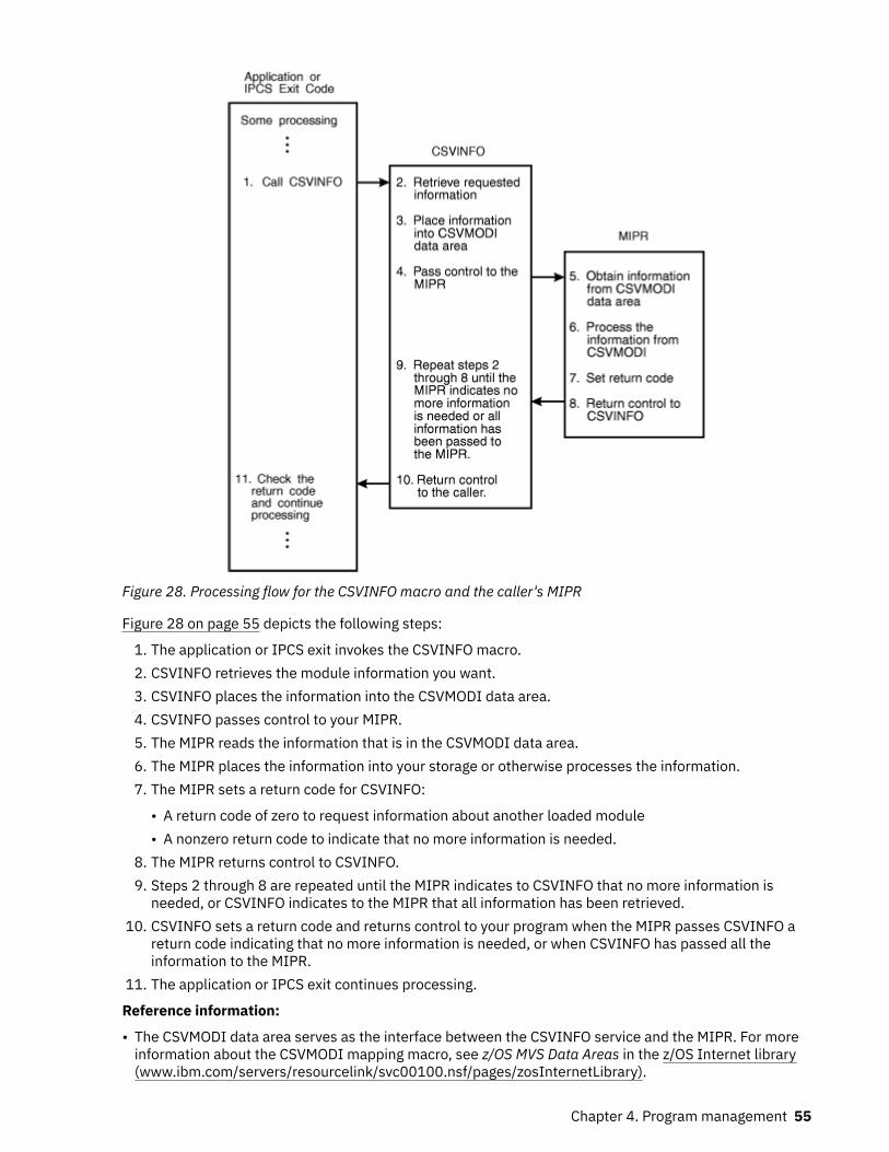
Figure 28. Processing flow for the CSVINFO macro and the caller's MIPR
Figure 28 on page 55 depicts the following steps:
1. The application or IPCS exit invokes the CSVINFO macro.2. CSVINFO retrieves the module information you want.3. CSVINFO places the information into the CSVMODI data area.4. CSVINFO passes control to your MIPR.5. The MIPR reads the information that is in the CSVMODI data area.6. The MIPR places the information into your storage or otherwise processes the information.7. The MIPR sets a return code for CSVINFO:
• A return code of zero to request information about another loaded module• A nonzero return code to indicate that no more information is needed.
8. The MIPR returns control to CSVINFO.9. Steps 2 through 8 are repeated until the MIPR indicates to CSVINFO that no more information is
needed, or CSVINFO indicates to the MIPR that all information has been retrieved.10. CSVINFO sets a return code and returns control to your program when the MIPR passes CSVINFO a
return code indicating that no more information is needed, or when CSVINFO has passed all theinformation to the MIPR.
11. The application or IPCS exit continues processing.
Reference information:
• The CSVMODI data area serves as the interface between the CSVINFO service and the MIPR. For moreinformation about the CSVMODI mapping macro, see z/OS MVS Data Areas in the z/OS Internet library(www.ibm.com/servers/resourcelink/svc00100.nsf/pages/zosInternetLibrary).
Chapter 4. Program management 55

• z/OS MVS IPCS Commands explains how to verify the correct use of the CSVINFO macro in an IPCS exit.See the TRAPON, TRAPOFF, and TRAPLIST subcommand descriptions.
• z/OS MVS IPCS Customization provides information about writing IPCS exits.
SerializationInformation about loaded modules in common storage is serialized by the LOCAL and CMS locks.Information about other loaded modules is serialized by the LOCAL lock. When the CSVINFO service runswith serialization, you are guaranteed that the information CSVINFO obtains is not in the process of beingupdated.
If your program runs in problem state and invokes the CSVINFO macro, your program cannot hold theappropriate locks and the CSVINFO service does not obtain them. Thus, the CSVINFO service retrievesinformation without serializing on it. If you are requesting information about loaded modules in commonstorage or if multi-tasking is taking place in your address space, the module information you requestmight be changing while the CSVINFO service is retrieving information. In rare instances, the CSVINFOservice could return incorrect information or end abnormally.
If your program runs in supervisor state and invokes the CSVINFO macro, the CSVINFO service obtainsthe appropriate locks if your program does not already hold them.
Coding a MIPR for the CSVINFO macroThis topic contains information about coding a MIPR.
Installing the MIPRYou can either link-edit your MIPR with the program that invokes the CSVINFO macro or include the MIPRin mainline code.
MIPR environmentThe MIPR receives control running under the unit of work that invoked the CSVINFO macro, in thefollowing environment:
Environment requirements:
Minimum authorization: Problem state and any PSW key.
Dispatchable unit mode: Task or SRB
Cross memory mode: PASN=HASN=SASN
AMODE: 31-bit
ASC mode: Primary
Interrupt status: Enabled for I/O and external interrupts
Control parameters: Control parameters must be in the primary address space.
Recovery for MIPR provided by CSVINFOTable 2 on page 56 shows the recovery environment that the CSVINFO service establishes for itself andthe MIPR.
Table 2. CSVINFO Recovery
ENV Keyword Caller State/Key Recovery Provided
ENV=MVS Supervisor state The caller's MIPR gets control with CSVINFO's FRRin effect.
56 z/OS: z/OS MVS Assembler Services Guide

Table 2. CSVINFO Recovery (continued)
ENV Keyword Caller State/Key Recovery Provided
ENV=MVS Problem state The caller's MIPR gets control with CSVINFO'sESTAE routine in effect.
ENV=IPCS Problem or supervisorstate
No recovery provided
Entry specificationsThe MIPR gets control through standard branch entry linkage. Input to the MIPR is the address of theCSVMODI data area, containing information from the CSVINFO service.
Registers at entryWhen the MIPR receives control, the general purpose registers (GPRs) contain the following information:GPR
Contents0
Does not contain any information for use by the routine1
Address of the CSVMODI data area2 - 12
Does not contain any information for use by the routine13
Address of a standard 72-byte save area14
Return address to the CSVINFO service15
Entry point address of MIPR
Return specificationsUpon return from MIPR processing, you must ensure that the register contents are as follows:
Registers at exitGPR
Contents0-1
The MIPR does not have to place any information into these registers, and does not have to restoretheir contents to what they were when the MIPR received control.
2-13The MIPR must restore the register contents to what they were when the MIPR received control.
14Return address to the CSVINFO service
15Return code from the MIPR
Note: The CSVINFO service continues processing until either of the following occurs:
• It receives a non-zero return code from the MIPR.• It has returned all available data
Chapter 4. Program management 57

When CSVINFO receives a non-zero return code, it returns control to the program that invoked theCSVINFO macro.
CSVINFO service coding exampleThe CSVSMIPR member of SAMPLIB contains a coded example of the use of the CSVINFO service and itsassociated MIPR. The sample program is a reentrant program that has its MIPR included within the samemodule.
58 z/OS: z/OS MVS Assembler Services Guide

Chapter 5. Understanding 31-bit addressing
Note to reader
This information documents the programming considerations for running 31-bit addressing modeprograms on previous versions and releases of MVS. Because this information might be useful forprogrammers who maintain or update legacy programs, the chapter is preserved to reflect theprogramming environment of previous MVS versions. If you intend to design and code a new program torun on z/OS releases, consider the following:
• Always design a program to run in 31-bit addressing mode, to take full advantage of the virtual storagecapacity of MVS.
• Use the IBM High Level Assembler, instead of Assembler H, to assemble the new program. As ofMVS/SP 5.2, Assembler H is not supported.
• Use the program management binder, instead of the linkage editor and loader, to prepare the programfor execution.
End of Note to reader
z/Architecture® supports 64-bit real and virtual addresses. For compatibility with Enterprise SystemsArchitecture (ESA) and 370/Extended Architecture (XA), z/Architecture also supports 31-bit real andvirtual addresses, which provide a maximum real and virtual address of two gigabytes minus one. Forcompatibility with older systems, z/Architecture also supports 24-bit real and virtual addresses.
The basic characteristics of the system that provide for 64-bit and 31-bit addresses and the continueduse of 24-bit addresses are:
• A virtual storage map of two gigabytes with most MVS services to support programs executing orresiding anywhere in the first two gigabytes of virtual storage. A virtual storage map of a theoretical 16exabytes to support programs executing in 64-bit mode.
• Two program attributes that specify expected address length on entry (addressing mode) and intendedlocation in virtual storage (residence mode).
• Trimodal operation, a capability of the processor that permits the execution of programs with 24-bitaddresses as well as programs with 31-bit and 64-bit addresses.
Virtual storageIn the MVS 31-bit virtual storage map:
• Each address space has its own two gigabytes of virtual storage.• Each private area has a portion below 16 megabytes and an extended portion above 16 megabytes but,
logically, these areas can be thought of as one area.
Figure 29 on page 60 shows the virtual storage map for 24-bit, 31-bit, and 64-bit addressing. While thistopic only discusses 31-bit addressing, the entire virtual storage map is shown. The 24-bit addressingrange ends at the 16 MB line, the 31-bit addressing range ends at the 2 GB bar, and the 64-bit addressingrange ends at 16 EB. 64-bit addressing is covered in Chapter 12, “Using the 64-bit address space,” onpage 201.
Addressing mode and residency modeThe processor can treat addresses as having either 24 or 31 bits. Addressing mode (AMODE) describeswhether the processor is using 24-bit or 31-bit addresses. Programs can reside in 24-bit addressableareas or beyond the 24-bit addressable area (above 16 megabytes). Residency mode (RMODE) specifieswhether the program must reside in the 24-bit addressable area or can reside anywhere in 31-bitaddressable storage.
© Copyright IBM Corp. 1988, 2020 59

Addressing mode (AMODE) and residency mode (RMODE) are program attributes specified (or defaulted)for each CSECT, load module, and load module alias. These attributes are the programmer's specificationof the addressing mode in which the program is expected to get control and where the program isexpected to reside in virtual storage.
AMODE defines the addressing mode (24, 31, or ANY) in which a program expects to receive control.Addressing mode refers to the address length that a program is prepared to handle on entry: 24-bitaddresses, 31-bit addresses, or both (ANY). Programs with an addressing mode of ANY have beendesigned to receive control in either 24- or 31-bit addressing mode.
Figure 29. Virtual storage map (not drawn to scale)
A 370-XA or 370-ESA processor can operate with either 24-bit addresses (16 megabytes ofaddressability) or 31-bit addresses (2 gigabytes of addressability). This ability of the processor to permitthe execution of programs in 24-bit addressing mode as well as programs in 31-bit addressing mode iscalled bimodal operation. A program's AMODE attribute determines whether the program is to receivecontrol with 24-bit or 31-bit addresses. Once a program gets control, the program can change the AMODEif necessary.
60 z/OS: z/OS MVS Assembler Services Guide

In 24-bit addressing mode, the processor treats all virtual addresses as 24-bit values. This makes itimpossible for a program in 24-bit addressing mode to address virtual storage with an address greaterthan 16,777,215 (16 megabytes) because that is the largest number that a 24-bit binary field can contain.
In 31-bit addressing mode, the processor treats all virtual addresses as 31-bit values.
The processor supports bimodal operation so that both new programs and most old programs canexecute correctly. Bimodal operation is necessary because certain coding practices in existing programsdepend on 24-bit addresses. For example:
• Some programs use a 4-byte field for a 24-bit address and place flags in the high-order byte.• Some programs use the LA instruction to clear the high-order byte of a register. (In 24-bit addressing
mode, LA clears the high-order byte; in 31-bit addressing mode, it clears only the high-order bit.)• Some programs depend on BAL and BALR to return the ILC (instruction length code), the CC (condition
code), and the program mask. (BAL and BALR return this information in 24-bit addressing mode. In 31-bit addressing mode they do not.)
Each load module and each alias entry has an AMODE attribute.
A CSECT can have only one AMODE, which applies to all its entry points. Different CSECTs in a loadmodule can have different AMODEs.
RMODE specifies where a program is expected to reside in virtual storage. The RMODE attribute is notrelated to central storage requirements. (RMODE 24 indicates that a program is coded to reside in virtualstorage below 16 megabytes. RMODE ANY indicates that a program is coded to reside anywhere in virtualstorage.)
Each load module and each alias entry has an RMODE attribute. The alias entry is assigned the sameRMODE as the main entry.
The following kinds of programs must reside in the range of addresses below 16 megabytes (addressableby 24-bit callers):
• Programs that have the AMODE 24 attribute• Programs that have the AMODE ANY attribute• Programs that use system services that require their callers to be AMODE 24• Programs that use system services that require their callers to be RMODE 24• Programs that must be addressable by 24-bit addressing mode callers
Programs without these characteristics can reside anywhere in virtual storage.
“Addressing mode and residency mode” on page 68 describes AMODE and RMODE processing and 31-bit addressing support of AMODE and RMODE in detail.
Requirements for execution in 31-bit addressing modeIn general, to execute in 31-bit addressing mode a program must:
• Be assembled using Assembler H Version 2 or High Level Assembler and using the z/OS macro library.• Be linked using the binder or linkage editor supplied with the operating system or be loaded using the
loader.
In general, to execute in 64-bit addressing mode a program must:
• Be assembled using High Level Assembler and the z/OS macro library.• Be linked using the binder or linkage editor supplied with the operating system or be loaded using the
loader.
Rules and conventions for 31-bit addressingIt is important to distinguish the rules from the conventions when describing 31-bit addressing. There areonly two rules, and they are associated with hardware:
Chapter 5. Understanding 31-bit addressing 61

1. The length of address fields is controlled by the A-mode bit (bit 32) in the PSW. When bit 32=1,addresses are treated as 31-bit values. When bit 32=0, addresses are treated as 24-bit values.
Any data passed from a 31-bit addressing mode program to a 24-bit addressing mode program mustreside in virtual storage below 16 megabytes. (A 24-bit addressing mode program cannot referencedata above 16 megabytes without changing addressing mode.)
2. The A-mode bit affects the way some instructions work.
The conventions, on the other hand, are more extensive. Programs using system services must followthese conventions.
• A program must return control in the same addressing mode in which it received control.• A program expects 24-bit addresses from 24-bit addressing mode programs and 31-bit addresses from
31-bit addressing mode programs.• A program should validate the high-order byte of any address passed by a 24-bit addressing mode
program before using it as an address in 31-bit addressing mode.
Mode sensitive instructionsThe processor is sensitive to the addressing mode that is in effect (the setting of the PSW A-mode bit).The current PSW controls instruction sequencing. The instruction address field in the current PSWcontains either a 24-bit address or a 31-bit address depending on the current setting of the PSW A-modebit. For those instructions that develop or use addresses, the addressing mode in effect in the currentPSW determines whether the addresses are 24 or 31 bits long.
Principles of Operation contains a complete description of the 370-XA and 370-ESA instructions. Thefollowing topics provide an overview of the mode sensitive instructions.
BAL and BALRBAL and BALR are addressing-mode sensitive. In 24-bit addressing mode, BAL and BALR work the sameway as they do when executed on a processor running in 370 mode. BAL and BALR put link informationinto the high-order byte of the first operand register and put the return address into the remaining threebytes before branching.
In 31-bit addressing mode, BAL and BALR put the return address into bits 1 through 31 of the firstoperand register and save the current addressing mode in the high-order bit. Because the addressingmode is 31-bit, the high-order bit is always a 1.
When executing in 31-bit addressing mode, BAL and BALR do not save the instruction length code, thecondition code, or the program mask. IPM (insert program mask) can be used to save the program maskand the condition code.
62 z/OS: z/OS MVS Assembler Services Guide

LAThe LA (load address) instruction, when executed in 31-bit addressing mode, loads a 31-bit value andclears the high-order bit. When executed in 24-bit addressing mode, it loads a 24-bit value and clears thehigh-order byte (as in MVS/370 mode).
LRAThe LRA (load real address) instruction always results in a 31-bit real address regardless of the issuingprogram's AMODE. The virtual address specified is treated as a 24-bit or 31-bit address based on thevalue of the PSW A-mode bit at the time the LRA instruction is executed.
Branching instructionsBASSM (branch and save and set mode) and BSM (branch and set mode) are branching instructions thatmanipulate the PSW A-mode bit (bit 32). Programs can use BASSM when branching to modules that mighthave different addressing modes. Programs invoked through a BASSM instruction can use a BSMinstruction to return in the caller's addressing mode. BASSM and BSM are described in more detail in“Establishing linkage” on page 77.
BAS (branch and save) and BASR:
• Save the return address and the current addressing mode in the first operand.• Replace the PSW instruction address with the branch address.
The high-order bit of the return address indicates the addressing mode. BAS and BASR perform the samefunction that BAL and BALR perform in 31-bit addressing mode. In 24-bit mode, BAS and BASR putzeroes into the high-order byte of the return address register.
Use of 31-bit addressingIn addition to providing support for the use of 31-bit addresses by user programs, MVS includes manysystem services that use 31-bit addresses.
Some system services are independent of the addressing mode of their callers. These services acceptcallers in either 24-bit or 31-bit addressing mode and use 31-bit parameter address fields. They assume24-bit addresses from 24-bit addressing mode callers and 31-bit addresses from 31-bit addressing modecallers. Most supervisor macros are in this category.
Other services have restrictions with respect to address parameter values. Some of these services acceptSVC callers and allow them to be in either 24-bit or 31-bit addressing mode. However, the same servicesmight require branch entry callers to be in 24-bit addressing mode or might require one or moreparameter addresses to be less than 16 megabytes.
Some services do not support 31-bit addressing at all. To determine a service's addressing moderequirements, see the documentation that explains how to invoke the service. (VSAM accepts entry by aprogram that executes in either 24-bit or 31-bit addressing mode.)
z/OS provides instructions that support 31-bit addressing mode and bimodal operation (31-bit and 24-bit). Your program also can be trimodal (64-bit, 31-bit and 24-bit) but that can be complicated so it israre. These instructions are supported by High Level Assembler. The binder and linkage editor functionsfor z/OS are described in z/OS MVS Program Management: User's Guide and Reference.
Planning for 31-bit addressingMost programs that run on MVS/370 will run in 24-bit addressing mode without change. Some programsneed to be modified to execute in 31-bit addressing mode to provide the same function. Still otherprograms need to be modified to run in 24-bit addressing mode.
The MVS conversion notebook helps you identify programs that need to be changed. You will need toconsult one or more versions of the MVS conversion notebook. The versions you need depend on your
Chapter 5. Understanding 31-bit addressing 63

current version of MVS and the version of MVS to which you are migrating. See the appropriate version ofthe MVS conversion notebook for your migration.
“Planning for 31-bit addressing” on page 63 helps you determine what changes to make to a module youare converting to 31-bit addressing and indicates 31-bit address considerations when writing new code.
Some reasons for converting to 31-bit addressing mode are:
• The program can use more virtual storage for tables, arrays, or additional logic.• The program needs to reference control blocks that have been moved above 16 megabytes.• The program is invoked by other 31-bit addressing mode programs.• The program must run in 31-bit addressing mode because it is a user exit routine that the system
invokes in 31-bit mode.• The program needs to invoke services that expect to get control in 31-bit addressing mode.
Converting existing programsKeeping in mind that 31-bit addressing mode programs can reside either below or above 16 megabytes,you can convert existing programs as follows:
1. Converting the program to use 31-bit addresses - a change in addressing mode only.
• You can change the entire module to use 31-bit addressing.• You can change only that portion that requires 31-bit addressing mode execution.
Be sure to consider whether or not the code has any dependencies on 24-bit addresses. Such codedoes not produce the same results in 31-bit mode as it did in 24-bit mode. See “Mode sensitiveinstructions” on page 62 for an overview of instructions that function differently depending onaddressing mode.
Figure 30 on page 64 summarizes the things that you need to do to maintain the proper interface witha program that you plan to change to 31-bit addressing mode.
Figure 30. Maintaining Correct Interfaces to Modules that Change to AMODE 312. Moving the program above 16 megabytes - a change in both addressing mode and residency mode
In general, you move an existing program above 16 megabytes because there is not enough room for itbelow 16 megabytes. For example:
• An existing program or application is growing so large that soon it will not fit below 16 megabytes.
64 z/OS: z/OS MVS Assembler Services Guide

• An existing application that now runs as a series of separate programs, or that executes in an overlaystructure, would be easier to manage as one large program.
• Code is in the system area, and moving it would provide more room for the private area below 16megabytes.
The techniques used to establish proper interfaces to modules that move above 16 megabytes depend onthe number of callers and the ways they invoke the module. Table 3 on page 65 summarizes thetechniques for passing control. The programs involved must ensure that any addresses passed asparameters are treated correctly. (High-order bytes of addresses to be used by a 31-bit addressing modeprogram must be validated or zeroed.)
Table 3. Establishing Correct Interfaces to Modules That Move Above 16 Megabytes
Means of Entry to Moved Module (AMODE31,RMODE ANY) Few AMODE 24,RMODE 24 Callers Many AMODE 24,RMODE 24 Callers
LOAD macro and BALR • Have caller use LINK OR LINKX
or• Have caller use LOAD macro and BASSM
(invoked program returns via BSM)
or• Change caller to AMODE 31,RMODE 24
before BALR
Create a linkage assist routine (described in“Establishing linkage” on page 77). Givethe linkage assist routine the name of themoved module.
BALR using an address in a common controlblock
• Have caller switch to AMODE 31 wheninvoking
or• Change the address in the control block to
a pointer-defined value (described in“Establishing linkage” on page 77) anduse BASSM. (The moved module will useBSM to return.)
Create a linkage assist routine (described in“Establishing linkage” on page 77).
ATTACH, ATTACHX, LINK, LINKX, XCTL, orXCTLX
No changes required. No changes required.
SYNCH or SYNCHX in AMODE 24 • Have caller use SYNCH or SYNCHX withAMODE=31 parameter
or• Have caller switch to AMODE 31 before
issuing SYNCH or SYNCHX.• Change address in the control block to a
pointer-defined value and use SYNCH orSYNCHX with AMODE=DEFINED.
Create a linkage assist routine (described in“Establishing linkage” on page 77).
In deciding whether or not to modify a program to execute in 31-bit addressing mode either below orabove 16 megabytes, there are several considerations:
1. How and by what is the module entered?2. What system and user services does the module use that do not support 31-bit callers or parameters?3. What kinds of coding practices does the module use that do not produce the same results in 31-bit
mode as in 24-bit mode?4. How are parameters passed? Can they reside above 16 megabytes?
Among the specific practices to check for are:
1. Does the module depend on the instruction length code, condition code, or program mask placed inthe high order byte of the return address register by a 24-bit mode BAL or BALR instruction? One wayto determine some of the dependencies is by checking all uses of the SPM (set program mask)instruction. SPM might indicate places where BAL or BALR were used to save the old program mask,which SPM might then have reset. The IPM (insert program mask) instruction can be used to save thecondition code and the program mask.
Chapter 5. Understanding 31-bit addressing 65

2. Does the module use an LA instruction to clear the high-order byte of a register? This practice will notclear the high-order byte in 31-bit addressing mode.
3. Are any address fields that are less than 4 bytes still appropriate? Make sure that a load instructiondoes not pick up a 4-byte field containing a 3-byte address with extraneous data in the high-orderbyte. Make sure that bits 1-7 are zero.
4. Does the program use the ICM (insert characters under mask) instruction? The use of this instruction issometimes a problem because it can put data into the high-order byte of a register containing anaddress, or it can put a 3-byte address into a register without first zeroing the register. If the register isthen used as a base, index, or branch address register in 31-bit addressing mode, it might not indicatethe proper address.
5. Does the program invoke 24-bit addressing mode programs? If so, shared data must be below 16megabytes.
6. Is the program invoked by 24-bit or 31-bit addressing mode programs? Is the data in an areaaddressable by the programs that need to use it? (The data must be below 16 megabytes if used by a24-bit addressing mode program.)
Writing new programs that use 31-bit addressingYou can write programs that execute in either 24-bit or 31-bit addressing mode. However, to maintain aninterface with existing programs and with some system services, your 31-bit addressing mode programsneed subroutines or portions of code that execute in 24-bit addressing mode. If your program residesbelow 16 megabytes, it can change to 24-bit addressing mode when necessary.
If your program resides above 16 megabytes, it needs a separate load module to perform the linkage toan unchanged 24-bit addressing mode program or service. Such load modules are called linkage assistroutines and are described in “Establishing linkage” on page 77.
When writing new programs, there are some things you can do to simplify the passing of parametersbetween programs that might be in different addressing modes. In addition, there are functions that youshould consider and that you might need to accomplish your program's objectives. Following is a list ofsuggestions for coding programs:
• Use fullword fields for addresses even if the addresses are only 24 bits in length.• When obtaining addresses from 3-byte fields in existing areas, use SR (subtract register) to zero the
register followed by ICM (insert characters under mask) in place of the load instruction to clear the high-order byte. For example:
Rather than: L 1,A
use: SR 1,1 ICM 1,7,A+1
The 7 specifies a 4-bit mask of 0111. The ICM instruction shown inserts bytes beginning at location A+1into register 1 under control of the mask. The bytes to be filled correspond to the 1 bits in the mask.Because the high-order byte in register 1 corresponds to the 0 bit in the mask, it is not filled.
• If the program needs storage above 16 megabytes, obtain the storage using the STORAGE macro or theVRU, VRC, RU, and RC forms of GETMAIN and FREEMAIN, or the corresponding functions on STORAGE.In addition, you can obtain storage above 16 megabytes by using CPOOL services. These are the onlyforms that allow you to obtain and free storage above 16 megabytes. Do not use storage areas above 16megabytes for save areas and parameters passed to other programs.
• Do not use the STAE macro; use ESTAE or ESTAEX. STAE has 24-bit addressing mode dependencies.• Do not use SPIE; use ESPIE. SPIE has 24-bit addressing mode dependencies.• Do not use previous paging services macros; use PGSER.• To make debugging easier, switch addressing modes only when necessary.• Identify the intended AMODE and RMODE for the program in a prologue.
66 z/OS: z/OS MVS Assembler Services Guide

• 31-bit addressing mode programs should use ESTAE, ESTAEX or the ESTAI parameter on the ATTACH,or ATTACHX macro rather than STAE or STAI. STAI has 24-bit addressing mode dependencies. Whenrecovery routines refer to the SDWA for PSW-related information, they should refer to SDWAEC1 (ECmode PSW at the time of error) and SDWAEC2 (EC mode PSW of the program request block (PRB) thatestablished the ESTAE-type recovery.
When writing new programs, you need to decide whether to use 24-bit addressing mode or 31-bitaddressing mode.
The following are examples of kinds of programs that you should write in 24-bit addressing mode:
– Programs that must execute on MVS/370 and do not require any new MVS functions.– Service routines, even those in the common area, that use system services requiring entry in 24-bit
addressing mode or that must accept control directly from unchanged 24-bit addressing modeprograms.
When you use 31-bit addressing mode, you must decide whether the new program should reside aboveor below 16 megabytes (unless it is so large that it will not fit below). Your decision depends on whatprograms and system services the new program invokes and what programs invoke it.
New programs below 16 megabytesThe main reason for writing new 31-bit addressing mode programs that reside below 16 megabytes is tobe able to address areas above 16 megabytes or to invoke 31-bit addressing mode programs while, at thesame time, simplifying communication with existing 24-bit addressing mode programs or systemservices, particularly data management. For example, VSAM macros accept callers in 24-bit or 31-bitaddressing mode.
Even though your program resides below 16 megabytes, you must be concerned about dealing withprograms that require entry in 24-bit addressing mode or that require parameters to be below 16megabytes. Figure 35 on page 78 in “Establishing linkage” on page 77 contains more information aboutparameter requirements.
New programs above 16 megabytesWhen you write new programs that reside above 16 megabytes, your main concerns are:
• Dealing with programs that require entry in 24-bit addressing mode or that require parameters to bebelow 16 megabytes. Note that these are concerns of any 31-bit addressing mode program no matterwhere it resides.
• How routines that remain below 16 megabytes invoke the new program.
Writing programs for MVS/370 and MVS systems with 31-bit addressingYou can write new programs that will run on systems that use 31-bit addressing. If these programs do notneed to use any new MVS functions, the best way to avoid errors is to assemble the programs on MVS/370with macro libraries from a 31-bit addressing system. You can also assemble these programs on 31-bitaddressing systems with macro libraries from MVS/370, but you must generate MVS/370-compatiblemacro expansions by specifying the SPLEVEL macro at the beginning of the programs.
Programs designed to execute on either 24 or 31-bit addressing systems must use fullword addresseswhere possible and use no new functions on macros except the LOC parameter on GETMAIN. Theseprograms must also be aware of downward incompatible macros and use SPLEVEL as needed.
SPLEVEL macroSome macros are downward incompatible. The level of the macro expansion generated during assemblydepends on the value of an assembler language global SET symbol.
The SPLEVEL macro allows programmers to change the value of the SET symbol. The SPLEVEL macro setsa default value of 5 for the SET symbol. Therefore, unless a program or installation specifically changesthe default value, the macros generated are z/OS macro expansions.
Chapter 5. Understanding 31-bit addressing 67

The SPLEVEL macro sets the SET symbol value for that program's assembly only and affects only theexpansions within the program being assembled. A single program can include multiple SPLEVEL macrosto generate different macro expansions. The following example shows how to obtain different macroexpansions within the same program by assembling both expansions and making a test at execution timeto determine which expansion to execute.
* DETERMINE WHICH SYSTEM IS EXECUTING TM CVTDCB,CVTMVSE (CVTMVSE is bit 0 in the BO SP2 CVTDCB field.)* INVOKE THE MVS/370 VERSION OF THE WTOR MACRO SPLEVEL SET=1 WTOR ..... B CONTINUESP2 EQU ** INVOKE THE VERSION OF THE WTOR MACRO SPLEVEL SET=2 WTOR ......CONTINUE EQU *
z/OS MVS Programming: Assembler Services Guide and z/OS MVS Programming: Assembler ServicesReference IAR-XCT describe the SPLEVEL macro.
Certain macros produce a “map” of control blocks or parameter lists. These mapping macros do notsupport the SPLEVEL macro. Mapping macros for different levels of MVS systems are available only in themacro libraries for each system. When programs use mapping macros, a different version of the programmay be needed for each system.
Dual programsSometimes two programs may be required, one for each system. In this case, use one of the followingapproaches:
• Keep each in a separate library• Keep both in the same library but under different names
Addressing mode and residency modeEvery program that executes is assigned two program attributes: an addressing mode (AMODE) and aresidency mode (RMODE). Programmers can specify these attributes for new programs. Programmers canalso specify these attributes for old programs through reassembly, linkage editor PARM values, linkageeditor MODE control statements, or loader PARM values. MVS assigns default attributes to any programthat does not have AMODE and RMODE specified.
Addressing mode - AMODEAMODE is a program attribute that can be specified (or defaulted) for each CSECT, load module, and loadmodule alias. AMODE states the addressing mode that is expected to be in effect when the program isentered. AMODE can have one of the following values:
• AMODE 24 - The program is designed to receive control in 24-bit addressing mode.• AMODE 31 - The program is designed to receive control in 31-bit addressing mode.• AMODE ANY - The program is designed to receive control in either 24-bit or 31-bit addressing mode.
Residency mode - RMODERMODE is a program attribute that can be specified (or defaulted) for each CSECT, load module, and loadmodule alias. RMODE states the virtual storage location (either above 16 megabytes or anywhere invirtual storage) where the program should reside. RMODE can have the following values:
• RMODE 24 - The program is designed to reside below 16 megabytes in virtual storage. MVS places theprogram below 16 megabytes.
68 z/OS: z/OS MVS Assembler Services Guide

• RMODE ANY - The program is designed to reside at any virtual storage location, either above or below16 megabytes. MVS places the program above 16 megabytes unless there is no suitable virtual storageabove 16 megabytes.
AMODE and RMODE combinationsFigure 31 on page 69 shows all possible AMODE and RMODE combinations and indicates which arevalid.
AMODE and RMODE combinations at execution timeAt execution time, there are only three valid AMODE/RMODE combinations:
1. AMODE 24, RMODE 24, which is the default2. AMODE 31, RMODE 243. AMODE 31, RMODE ANY
The ATTACH, ATTACHX, LINK, LINKX, XCTL, and XCTLX macros give the invoked module control in theAMODE previously specified. However, specifying a particular AMODE does not guarantee that a modulethat gets control by other means will receive control in that AMODE. For example, an AMODE 24 modulecan issue a BALR to an AMODE 31, RMODE 24 module. The AMODE 31 module will get control in 24-bitaddressing mode.
1.This combination is invalid because an AMODE 24 module cannot reside above 16 megabytes.
2.This is a valid combination in that the assembler, linkage editor, and loader accept it from all sources.However, the combination is not used at execution time. Specifying ANY is a way of deferring adecision about the actual AMODE until the last possible moment before execution. At execution time,however, the module must execute in either 24-bit or 31-bit addressing mode.
3.The attributes AMODE ANY/RMODE ANY take on a special meaning when used together. (Thismeaning might seem to disagree with the meaning of either taken alone.) A module with the AMODEANY/RMODE ANY attributes will execute on either an MVS/370 or a system that uses 31-bitaddressing if the module is designed to:
• Use no facilities that are unique.• Execute entirely in 31-bit addressing mode on a system that uses 31-bit addressing and return
control to its caller in 31-bit addressing mode. (The AMODE could be different from invocation toinvocation.)
• Execute entirely in 24-bit addressing mode on an MVS/370 system.
The linkage editor and loader accept this combination from the object module or load module but notfrom the PARM field of the linkage editor EXEC statement or the linkage editor MODE controlstatement. The linkage editor converts AMODE ANY/RMODE ANY to AMODE 31/RMODE ANY.
Figure 31. AMODE and RMODE Combinations
Determining the AMODE and RMODE of a load moduleUse the AMBLIST service aid to find out the AMODE and RMODE of a load module. The module summaryproduced by the LISTLOAD control statement contains the AMODE of the main entry point and the AMODE
Chapter 5. Understanding 31-bit addressing 69

of each alias, as well as the RMODE specified for the load module. Refer to z/OS MVS Diagnosis: Tools andService Aids for information about AMBLIST.
You can look at the source code to determine the AMODE and RMODE that the programmer intended forthe program. However, the linkage editor or the loader can override these specifications.
Assembler support of AMODE and RMODEAssembler H Version 2 and High Level Assembler support AMODE and RMODE assembler instructions.Using AMODE and RMODE assembler instructions, you can specify an AMODE and an RMODE to beassociated with a control section, an unnamed control section, or a named common control section.
AMODE and RMODE in the object moduleThe only combination of AMODE and RMODE that is not valid is AMODE 24/ RMODE ANY.
The following errors will keep your program from assembling:
• Multiple AMODE/RMODE statements for a single control section• An AMODE/RMODE statement with an incorrect or missing value• An AMODE/RMODE statement whose name field is not that of a valid control section in the assembly.
AMODE and RMODE assembler instructionsThe AMODE instruction specifies the addressing mode to be associated with a CSECT in an object module.The format of the AMODE instruction is:
Name Operation Operand
Any symbol or blank AMODE 24/31/ANY
The name field associates the addressing mode with a control section. If there is a symbol in the namefield of an AMODE statement, that symbol must also appear in the name field of a START, CSECT, or COMstatement in the assembly. If the name field is blank, there must be an unnamed control section in theassembly.
Similarly, the name field associates the residency mode with a control section. The RMODE statementspecifies the residency mode to be associated with a control section. The format of the RMODEinstruction is:
Name Operation Operand
Any symbol or blank RMODE 24/ANY
Both the RMODE and AMODE instructions can appear anywhere in the assembly. Their appearance doesnot initiate an unnamed CSECT. There can be more than one RMODE (or AMODE) instruction perassembly, but they must have different name fields.
The defaults when AMODE, RMODE, or both are not specified are:
Specified Defaulted
Neither AMODE 24 RMODE 24
AMODE 24 RMODE 24
AMODE 31 RMODE 24
AMODE ANY RMODE 24
RMODE 24 AMODE 24
RMODE ANY AMODE 31
70 z/OS: z/OS MVS Assembler Services Guide

Linkage editor and binder support of AMODE and RMODEThe linkage editor accepts AMODE and RMODE specifications from any or all of the following:
• Object modules.• Load modules.• PARM field of the linkage editor EXEC statement. For example:
//LKED EXEC PGM=name,PARM='AMODE=31,RMODE=ANY,.....'
PARM field input overrides object module and load module input.• Linkage editor MODE control statements in the SYSLIN data set. For example:
MODE AMODE(31),RMODE(24)
MODE control statement input overrides object module, load module and PARM input.
Linkage editor processing results in two sets of AMODE and RMODE indicators located in:
• The load module• The PDS entry for the member name and any PDS entries for alternate names or alternate entry points
that were constructed using the linkage editor ALIAS control statement.
These two sets of indicators might differ because they can be created from different input. The linkageeditor creates indicators in the load module based on input from the input object module and loadmodule. The linkage editor creates indicators in the PDS directory based not only on input from the objectmodule and load module but also on the PARM field of the linkage editor EXEC statement, and the MODEcontrol statements in the SYSLIN data set. The last two sources of input override indicators from theobject module and load module. Figure 32 on page 72 shows linkage editor processing of AMODE andRMODE.
Chapter 5. Understanding 31-bit addressing 71

Figure 32. AMODE and RMODE Processing by the Linkage Editor
The linkage editor and binder use default values of AMODE 24 and RMODE 24 for:
• Object modules produced by assemblers older than Assembler H Version 2 and High Level Assembler• Object modules produced by Assembler H Version 2 or High Level Assembler where source statements
did not specify AMODE or RMODE• Load modules produced by linkage editors older than the MVS/XA linkage editor
72 z/OS: z/OS MVS Assembler Services Guide

• Load modules produced by the linkage editor that did not have AMODE or RMODE specified from anyinput source
• Load modules in overlay structure
Treat programs in overlay structure as AMODE 24, RMODE 24 programs. Putting a program into overlaystructure destroys any AMODE and RMODE specifications contained in the load module.
The linkage editor recognizes as valid the following combinations of AMODE and RMODE:AMODE 24
RMODE 24AMODE 31
RMODE 24AMODE 31
RMODE ANYAMODE ANY
RMODE 24AMODE ANY
RMODE ANY
The linkage editor accepts the ANY/ANY combination from the object module or load module and placesAMODE 31, RMODE ANY into the PDS (unless overridden by PARM values or MODE control statements).The linkage editor does not accept ANY/ANY from the PARM value or MODE control statement.
Any AMODE value specified alone in the PARM field or MODE control statement implies an RMODE of 24.Likewise, an RMODE of ANY specified alone implies an AMODE of 31. However, for RMODE 24 specifiedalone, the linkage editor does not assume an AMODE value. Instead, it uses the AMODE value specified inthe CSECT in generating the entry or entries in the PDS.
When the linkage editor creates an overlay structure, it assigns AMODE 24, RMODE 24 to the resultingprogram.
Linkage editor RMODE processingIn constructing a load module, the linkage editor frequently is requested to combine multiple CSECTs, orit may process an existing load module as input, combining it with additional CSECTs or performing aCSECT replacement.
The linkage editor determines the RMODE of each CSECT. If the RMODEs are all the same, the linkageeditor assigns that RMODE to the load module. If the RMODEs are not the same (ignoring the RMODEspecification on common sections), the more restrictive value, RMODE 24, is chosen as the load module'sRMODE.
The RMODE chosen can be overridden by the RMODE specified in the PARM field of the linkage editorEXEC statement. Likewise, the PARM field RMODE can be overridden by the RMODE value specified on thelinkage editor MODE control statement.
The linkage editor does not alter the RMODE values obtained from the object module or load modulewhen constructing the new load module. Any choice that the linkage editor makes or any overrideprocessing that it performs affects only the PDS.
Loader support for AMODE and RMODEThe loader's processing of AMODE and RMODE is similar to the linkage editor's. The loader acceptsAMODE and RMODE specifications from:
• Object modules• Load modules• PARM field of the JCL EXEC statement
Chapter 5. Understanding 31-bit addressing 73

Unlike the linkage editor, the loader does not accept MODE control statements from the SYSLIN data set,but it does base its loading sequence on the sequence of items in SYSLIN.
The loader passes the AMODE value to MVS. The loader processes the RMODE value as follows. If theuser specifies an RMODE value in the PARM field, that value overrides any previous RMODE value. Usingthe value of the first RMODE it finds in the first object module or load module it encounters that is not for acommon section, the loader obtains virtual storage for its output. As the loading process continues, theloader may encounter a more restrictive RMODE value. If, for example, the loader begins loading based onan RMODE ANY indicator and later finds an RMODE 24 indicator in a section other than a common section,it issues a message and starts over based on the more restrictive RMODE value. Figure 33 on page 74shows loader processing of AMODE and RMODE.
Figure 33. AMODE and RMODE Processing by the Loader
System support of AMODE and RMODEThe following are examples of system support of AMODE and RMODE:
• The system obtains storage for the module as indicated by RMODE.• ATTACH, ATTACHX, LINK, LINKX, XCTL, and XCTLX give the invoked module control in the addressing
mode specified by its AMODE.• LOAD brings a module into storage based on its RMODE and sets bit 0 in register 0 to indicate its
AMODE.
74 z/OS: z/OS MVS Assembler Services Guide

• CALL passes control in the AMODE of the caller.• SYNCH or SYNCHX has an AMODE parameter that you can use to specify the AMODE of the invoked
module.• For SVCs, the system saves and sets the addressing mode.• SRBs are dispatched in the addressing mode indicated by the SRB specified to the SCHEDULE macro.• The cross memory instructions PC and PT establish the addressing mode for the target program.• Access methods support all valid combinations of AMODE and RMODE with these exceptions:
– AMODE 64 and RMODE 64 are not supported unless otherwise documented for the interface.– Some devices such as unit record devices and TSO terminals have documented restrictions.
• Dumping is based on the AMODE specified in the error-related PSW.
Program FetchThe system uses RMODE information from the PDS to determine whether to obtain storage above orbelow 16 megabytes.
ATTACH, ATTACHX, LINK, LINKX, XCTL, and XCTLXIssuing an ATTACH or ATTACHX macro causes the control program to create a new task and indicatesthe entry point to be given control when the new task becomes active. If the entry point is a membername or an alias in the PDS. ATTACH or ATTACHX gives it control in the addressing mode specified inthe PDS or in the mode specified by the loader. If the invoked program has the AMODE ANY attribute,it gets control in the AMODE of its caller.
The LINK, LINKX, XCTL, and XCTLX macros also give the invoked program control in the addressingmode indicated by its PDS for programs brought in by fetch or in the AMODE specified by the loader.The entry point specified must be a member name or an alias in the PDS passed by the loader, orspecified in an IDENTIFY macro. If the entry point is an entry name specified in an IDENTIFY macro,IDENTIFY sets the addressing mode of the entry name equal to the addressing mode of the mainentry point.
LOADIssuing the LOAD macro causes MVS to bring the load module containing the specified entry pointname into virtual storage (if a usable copy is not already there). LOAD sets the high-order bit of theentry point address in register 0 to indicate the module's AMODE (0 for 24, 1 for 31), which LOADobtains from the module's PDS entry. If the module's AMODE is ANY, LOAD sets the high-order bit inregister 0 to correspond to the caller's AMODE.
LOAD places the module in virtual storage either above or below 16 megabytes as indicated by themodule's RMODE, which is specified in the PDS for the module.
Specifying the ADDR parameter indicates that you want the module loaded at a particular location. Ifyou specify an address above 16 megabytes, be sure that the module being loaded has the RMODEANY attribute. If you do not know the AMODE and RMODE attributes of the module, specify anaddress below 16 megabytes or omit the ADDR parameter.
CALLThe CALL macro passes control to an entry point via BALR. Thus control is transferred in the AMODE ofthe caller. CALL does not change AMODE.
SYNCH or SYNCHXUsing the AMODE parameter on the SYNCH or SYNCHX macro, you can specify the addressing mode inwhich the invoked module is to get control. Otherwise, SYNCH or SYNCHX passes control in thecaller's addressing mode.
SVCFor SVCs (supervisor calls), the system saves and restores the issuer's addressing mode and makessure that the invoked service gets control in the specified addressing mode.
Chapter 5. Understanding 31-bit addressing 75

SRBWhen an SRB (service request block) is dispatched, the system sets the addressing mode based onthe high-order bit of the SRBEP field. This bit, set by the issuer of the SCHEDULE macro, indicates theaddressing mode of the routine operating under the dispatched SRB.
PC and PTFor a program call (PC), the entry table indicates the target program's addressing mode. The addressfield in the entry table must be initialized by setting the high-order bit to 0 for 24-bit addressing modeor to 1 for 31-bit addressing mode.
The PC instruction sets up register 14 with the return address and AMODE for use with the PT(program transfer) instruction. If PT is not preceded by a PC instruction, the PT issuer must set thehigh-order bit of the second operand register to indicate the AMODE of the program being entered (0for 24-bit addressing mode or 1 for 31-bit addressing mode).
Data Management Access MethodsUser programs can be in AMODE 24 or AMODE 31 when invoking access methods except with certaindevices. The non-VSAM access methods require certain parameter lists, control blocks and user exitroutines to reside in virtual storage below 16 megabytes. Some interfaces support only AMODE 24and some support AMODE 64. See z/OS DFSMS Using Data Sets and z/OS DFSMS Macro Instructionsfor Data Sets.
AMODE's Effect on DumpsThe only time AMODE has an effect on dumps is when data on either side of the address in eachregister is dumped. If the addresses in registers are treated as 24-bit addresses, the data dumpedmay come from a different storage location than when the addresses are treated as 31-bit addresses.If a dump occurs shortly after an addressing mode switch, some registers may contain 31-bitaddresses and some may contain 24 bit addresses, but dumping services does not distinguish amongthem. Dumping services uses the AMODE from the error-related PSW. For example, in dumping thearea related to the registers saved in the SDWA, dumping services uses the AMODE from the errorPSW stored in the SDWA.
How to change addressing modeTo change addressing mode you must change the value of the PSW A-mode bit. The following list includesall the ways to change addressing mode.
• The mode setting instructions BASSM and BSM.• Macros (ATTACH, ATTACHX, LINK, LINKX, XCTL, or XCTLX). The system makes sure that routines get
control in the specified addressing mode. Users need only ensure that parameter requirements are met.MVS restores the invoker's mode on return from LINK or LINKX.
• SVCs. The supervisor saves and restores the issuer's addressing mode and ensures that the serviceroutine receives control in the addressing mode specified in its SVC table entry.
• SYNCH or SYNCHX with the AMODE parameter to specify the addressing mode in which the invokedroutine is to get control.
• The CIRB macro and the stage 2 exit effector. The CIRB macro is described in z/OS MVS Programming:Authorized Assembler Services Guide and z/OS MVS Programming: Authorized Assembler ServicesReference ALE-DYN.
• A PC, PT, or PR instruction. These three instructions establish the specified addressing mode.• An LPSW instruction (not recommended).
The example in Figure 34 on page 77 illustrates how a change in addressing mode in a 24-bit addressingmode program enables the program to retrieve data from the ACTLB control block, which might resideabove 16 megabytes. The example works correctly whether or not the control block is actually above 16megabytes. The example uses the BSM instruction to change addressing mode. In the example, theinstruction L 2,4(,15) must be executed in 31-bit addressing mode. Mode setting code (BSM) before theinstruction establishes 31-bit addressing mode and code following the instruction establishes 24-bitaddressing mode.
76 z/OS: z/OS MVS Assembler Services Guide

USER CSECTUSER RMODE 24USER AMODE 24 L 15,ACTLB L 1,LABEL1 SET HIGH-ORDER BIT OF REGISTER 1 TO 1 AND PUT ADDRESS INTO BITS 1-31 BSM 0,1 SET AMODE 31 (DOES NOT PRESERVE AMODE)LABEL1 DC A(LABEL2 + X'80000000')LABEL2 DS 0H L 2,4(,15) OBTAIN DATA FROM ABOVE 16 MEGABYTES LA 1,LABEL3 SET HIGH-ORDER BIT OF REGISTER 1 TO 0 AND PUT ADDRESS INTO BITS 1-31 BSM 0,1 SET AMODE 24 (DOES NOT PRESERVE AMODE)LABEL3 DS 0H
Figure 34. Mode Switching to Retrieve Data from Above 16 Megabytes
Establishing linkageThis information describes the mechanics of correct linkage in 31-bit addressing mode. Keep in mind thatthere are considerations other than linkage, such as locations of areas that both the calling module andthe invoked module need to address.
As shown in Figure 35 on page 78, it is the linkage between modules whose addressing modes aredifferent that is an area of concern. The areas of concern that appear in Figure 35 on page 78 fall intotwo basic categories:
• Addresses passed as parameters from one routine to another must be addresses that both routines canuse.
– High-order bytes of addresses must contain zeroes or data that the receiving routine is programmedto expect.
– Addresses must be less than 16 megabytes if they could be passed to a 24-bit addressing modeprogram.
• On transfers of control between programs with different AMODEs, the receiving routine must get controlin the AMODE it needs and return control to the calling routine in the AMODE the calling routine needs.
There are a number of ways of dealing with the areas of concern that appear in Figure 35 on page 78:
• Use the branching instructions (BASSM and BSM)• Use pointer-defined linkage• Use supervisor-assisted linkage (ATTACH, ATTACHX, LINK, LINKX, XCTL, and XCTLX)• Use linkage assist routines• Use “capping.”
Chapter 5. Understanding 31-bit addressing 77

Figure 35. Linkage Between Modules with Different AMODEs and RMODEs
Using the BASSM and BSM instructionsThe BASSM (branch and save and set mode) and the BSM (branch and set mode) instructions arebranching instructions that set the addressing mode. They are designed to complement each other.(BASSM is used to call and BSM is used to return, but they are not limited to such use.)
The description of BASSM appears in Figure 36 on page 79. (See Principles of Operation for moreinformation.)
78 z/OS: z/OS MVS Assembler Services Guide

Bits 32-63 of the current PSW, including the updated instruction address, are saved as link informationin the general register designated by R1. Subsequently, the addressing mode and instruction address inthe current PSW are replaced from the second operand. The action associated with the secondoperand is not performed if the R2 field is zero.
The contents of the general register designated by the R2 field specify the new addressing mode andbranch address; however when the R2 field is zero, the operation is performed without branching andwithout setting the addressing mode.
When the contents of the general register designated by the R2 field are used, bit 0 of the registerspecifies the new addressing mode and replaces bit 32 of the current PSW, and the branch address isgenerated from the contents of the register under the control of the new addressing mode. The newvalue for the PSW is computed before the register designated by R1 is changed.
Condition Code: The code remains unchanged.
Program Exceptions: Trace (R2 field is not zero).
Figure 36. BRANCH and SAVE and Set Mode Description
The description of BSM appears in Figure 37 on page 79. (See Principles of Operation for moreinformation.)
Bit 32 of the current PSW, the addressing mode, is inserted into the first operand. Subsequently theaddressing mode and instruction address in the current PSW are replaced from the second operand.The action associated with an operand is not performed if the associated R field is zero.
The value of bit 32 of the PSW is placed in bit position 0 of the general register designated by R1, andbits 1-31 of the register remain unchanged; however, when the R1 field is zero, the bit is not inserted,and the contents of general register 0 are not changed.
The contents of the general register designated by the R2 field specify the new addressing mode andbranch address; however, when the R2 field is zero, the operation is performed without branching andwithout setting the addressing mode.
When the contents of the general register designated by the R2 field are used, bit 0 of the registerspecifies the new addressing mode and replaces bit 32 of the current PSW, and the branch address isgenerated from the contents of the register under the control of the new addressing mode. The newvalue for the PSW is computed before the register designated by R1 is changed.
Condition Code: The code remains unchanged.
Program Exceptions: None.
Figure 37. Branch and Set Mode Description
Calling and returning with BASSM and BSMIn the following example, a module named BELOW has the attributes AMODE 24, RMODE 24. BELOW usesa LOAD macro to obtain the address of module ABOVE. The LOAD macro returns the address in register 0
Chapter 5. Understanding 31-bit addressing 79

with the addressing mode indicated in bit 0 (a pointer-defined value). BELOW stores this address inlocation EPABOVE. When BELOW is ready to branch to ABOVE, BELOW loads ABOVE's entry point addressfrom EPABOVE into register 15 and branches using BASSM 14,15. BASSM places the address of the nextinstruction into register 14 and sets bit 0 in register 14 to 0 to correspond to BELOW's addressing mode.BASSM replaces the PSW A-mode bit with bit 0 of register 15 (a 1 in this example) and replaces the PSWinstruction address with the branch address (bits 1-31 of register 15) causing the branch.
ABOVE uses a BSM 0,14 to return. BSM 0,14 does not save ABOVE's addressing mode because 0 isspecified as the first operand register. It replaces the PSW A-mode bit with bit 0 of register 14 (BELOW'saddressing mode set by BASSM) and branches.
Figure 38. Using BASSM and BSM
Using pointer-defined linkagePointer-defined linkage is a convention whereby programs can transfer control back and forth withouthaving to know each other's AMODEs. Pointer-defined linkage is simple and efficient. You should use it innew or modified modules where there might be mode switching between modules.
Pointer-defined linkage uses a pointer-defined value, which is a 4-byte area that contains both anAMODE indicator and an address. The high-order bit contains the AMODE; the remainder of the wordcontains the address. To use pointer-defined linkage, you must:
• Use a pointer-defined value to indicate the entry point address and the entry point's AMODE. (The LOADmacro provides a pointer-defined value.)
• Use the BASSM instruction specifying a register that contains the pointer-defined value. BASSM savesthe caller's AMODE and next the address of the next sequential instruction, sets the AMODE of thetarget routine, and branches to the specified location.
• Have the target routine save the full contents of the return register and use it in the BSM instruction toreturn to the caller.
80 z/OS: z/OS MVS Assembler Services Guide

Using an ADCON to obtain a pointer-defined valueThe following method is useful when you need to construct pointer-defined values to use in pointer-defined linkages between control sections or modules that will be link edited into a single load module.You can also use this method when the executable program is prepared in storage using the loader.
The method requires the use of an externally-defined address constant in the routine to be invoked thatidentifies its entry mode and address. The address constant must contain a pointer-defined value. Thecalling program loads the pointer-defined value and uses it in a BASSM instruction. The invoked routinereturns using a BSM instruction.
In Figure 39 on page 81, RTN1 obtains pointer-defined values from RTN2 and RTN3. RTN1, the invokingroutine does not have to know the addressing modes of RTN2 and RTN3. Later, RTN2 or RTN3 could bechanged to use different addressing modes, and at that time their address constants would be changed tocorrespond to their new addressing mode. RTN1, however, would not have to change the sequence ofcode it uses to invoke RTN2 and RTN3.
You can use the techniques that the previous example illustrates to handle routines that have multipleentry points (possibly with different AMODE attributes). You need to construct a table of addressconstants, one for each entry point to be handled.
As with all forms of linkage, there are considerations in addition to the linkage mechanism. These include:
• Both routines must have addressability to any parameters passed.• Both routines must agree which of them will clean up any 24-bit addresses that might have extraneous
information bits 1-7 of the high-order byte. (This is a consideration only for AMODE 31 programs.)
When a 24-bit addressing mode program invokes a module that is to execute in 31-bit addressing mode,the calling program must ensure that register 13 contains a valid 31-bit address of the register save areawith no extraneous data in bits 1-7 of the high-order byte. In addition, when any program invokes a 24-bitaddressing mode program, register 13 must point to a register save area located below 16 megabytes.
RTN1 CSECT EXTRN RTN2AD EXTRN RTN3AD . . L 15,=A(RTN2AD) LOAD ADDRESS OF POINTER-DEFINED VALUE L 15,0(,15) LOAD POINTER-DEFINED VALUE BASSM 14,15 GO TO RTN2 VIA BASSM . . L 15,=A(RTN3AD) LOAD ADDRESS OF POINTER-DEFINED VALUE L 15,0(,15) LOAD POINTER DEFINED-VALUE BASSM 14,15 GO TO RTN3 VIA BASSM .
__________________________________________________________________RTN2 CSECTRTN2 AMODE 24 ENTRY RTN2AD . BSM 0,14 RETURN TO CALLER IN CALLER'S MODERTN2AD DC A(RTN2) WHEN USED AS A POINTER-DEFINED VALUE, INDICATES AMODE 24 BECAUSE BIT 0 IS 0
__________________________________________________________________RTN3 CSECTRTN3 AMODE 31 ENTRY RTN3AD . BSM 0,14 RETURN TO CALLER IN CALLER'S MODERTN3AD DC A(X'80000000'+RTN3) WHEN USED AS A POINTER-DEFINED VALUE INDICATES AMODE 31 BECAUSE BIT 0 IS 1
Figure 39. Example of Pointer-Defined Linkage
Chapter 5. Understanding 31-bit addressing 81

Using the LOAD macro to obtain a pointer-defined valueLOAD returns a pointer-defined value in register 0. You can preserve this pointer-defined value and use itwith a BASSM instruction to pass control without having to know the target routine's AMODE.
Using supervisor-assisted linkageFigure 40 on page 83 shows a “before” and “after” situation involving two modules, MOD1 and MOD2. Inthe BEFORE part of the figure both modules execute in 24-bit addressing mode. MOD1 invokes MOD2using the LINK or LINKX macro. The AFTER part of the figure shows MOD2 moving above 16 megabytesand outlines the steps that were necessary to make sure both modules continue to perform their previousfunction.
82 z/OS: z/OS MVS Assembler Services Guide

Figure 40. Example of Supervisor-Assisted Linkage
Linkage assist routinesA linkage assist routine, sometimes called an addressing mode interface routine, is a module thatperforms linkage for modules executing in different addressing or residency modes. Using a linkage assistroutine, a 24-bit addressing mode module can invoke a 31-bit addressing mode module without having to
Chapter 5. Understanding 31-bit addressing 83

make any changes. The invocation results in an entry to a linkage assist routine that resides below 16megabytes and invokes the 31-bit addressing mode module in the specified addressing mode.
Conversely, a 31-bit addressing mode module, such as a new user module, can use a linkage assistroutine to communicate with other user modules that execute in 24-bit addressing mode. The callerappears to be making a direct branch to the target module, but branches instead to a linkage assistroutine that changes modes and performs the branch to the target routine.
The main advantage of using a linkage assist routine is to insulate a module from addressing modechanges that are occurring around it.
The main disadvantage of using a linkage assist routine is that it adds overhead to the interface. Inaddition, it takes time to develop and test the linkage assist routine. Some alternatives to using linkageassist routines are:
• Changing the modules to use pointer-defined linkage (described in “Using pointer-defined linkage” onpage 80).
• Adding a prologue and epilogue to a module to handle entry and exit mode switching, as described laterin this chapter under “Capping.”
Example of using a linkage assist routineFigure 41 on page 85 shows a “before” and “after” situation involving modules USER1 and USER2.USER1 invokes USER2 by using a LOAD and BALR sequence. The “before” part of the figure shows USER1and USER2 residing below 16 megabytes and lists the changes necessary if USER2 moves above 16megabytes. USER1 does not change.
The “after” part of the figure shows how things look after USER2 moves above 16 megabytes. Note thatUSER2 is now called USER3 and the newly created linkage assist routine has taken the name USER2.
The figure continues with a coding example that shows all three routines after the move.
84 z/OS: z/OS MVS Assembler Services Guide

Figure 41. Example of a Linkage Assist Routine
USER1 (This module will not change):
* USER MODULE USER1 CALLS MODULE USER2 00000100USER1 CSECT 00000200BEGIN SAVE (14,12),,* (SAVE REGISTER CONTENT, ETC.) 00000300* ESTABLISH BASE REGISTER(S) AND NEW SAVE AREA (NORMAL 00000400
Chapter 5. Understanding 31-bit addressing 85

* ENTRY CODING) 00000500 . .* ISSUE LOAD FOR MODULE USER2 00000700 LOAD EP=USER2 ISSUE LOAD FOR MODULE "USER2" 00000800* The LOAD macro returns a* pointer-defined value. However, because module USER1* has not been changed and executes in AMODE 24, the* pointer-defined value has no effect on the BALR* instruction used to branch to module USER2. ST 0,EPUSER2 PRESERVE ENTRY POINT 00000900 .* MAIN PROCESS BEGINS 00001000PROCESS DS 0H 00001100 . . . . . .* PREPARE TO GO TO MODULE USER2 00002000 L 15,EPUSER2 LOAD ENTRY POINT 00002100 BALR 14,15 00002200 . . . . TM TEST FOR END 00003000 BC PROCESS CONTINUE IN LOOP 00003100 . DELETE EP=USER2 L 13,4(13) RETURN (14,12),T,RC=0 MODULE USER1 COMPLETED 00005000EPUSER2 DC F'0' ADDRESS OF ENTRY POINT TO USER2 00007000 END BEGIN 00007100
USER2 (Original application module):
* USER MODULE USER2 (INVOKED FREQUENTLY FROM USER1) 00000100USER2 CSECT 00000200 SAVE (14,12),,* SAVE REGISTER CONTENT, ETC. 00000300* ESTABLISH BASE REGISTER(S) AND NEW SAVE AREA (NORMAL 00000400* ENTRY CODING) . . . . . L 13,4(13) RETURN (14,12),T,RC=0 MODULE USER2 COMPLETED 00008100 END 00008200
USER2 (New linkage assist routine):
* THIS IS A NEW LINKAGE ASSIST ROUTINE 0000100* (IT WAS NAMED USER2 SO THAT MODULE USER1 WOULD NOT 0000200* HAVE TO BE CHANGED) 0000300USER2 CSECT 0000400USER2 AMODE 24 0000500USER2 RMODE 24 0000600 SAVE (14,12),,* (SAVE REGISTER CONTENT, ETC.) 0000700* ESTABLISH BASE REGISTER(S) AND NEW SAVE AREA (NORMAL 0000800* ENTRY CODING) .* FIRST TIME LOGIC, PERFORMED ON INITIAL ENTRY ONLY, 0002000* (AFTER INITIAL ENTRY, BRANCH TO PROCESS (SHOWN BELOW)) 0002100 . GETMAIN NEW REGISTER SAVE AREA 0003000 . LOAD EP=USER3 0004000* USER2 LOADS USER3 BUT DOES NOT DELETE IT. USER2 CANNOT* DELETE USER3 BECAUSE USER2 DOES NOT KNOW WHICH OF ITS USES* OF USER3 IS THE LAST ONE. ST 0,EPUSER3 PRESERVE POINTER DEFINED VALUE 0004100 .* PROCESS (PREPARE FOR ENTRY TO PROCESSING MODULE) 0005000 . (FOR EXAMPLE, VALIDITY CHECK REGISTER CONTENTS) .
86 z/OS: z/OS MVS Assembler Services Guide

.* PRESERVE AMODE FOR USE DURING RETURN SEQUENCE 0007000 LA 1,XRETURN SET RETURN ADDRESS 0008000 BSM 1,0 PRESERVE CURRENT AMODE 0008100 ST 1,XSAVE PRESERVE ADDRESS 0008200 L 15,EPUSER3 LOAD POINTER DEFINED VALUE 0009000* GO TO MODULE USER3 0009100 BASSM 14,15 TO PROCESSING MODULE 0009200* RESTORE AMODE THAT WAS IN EFFECT 0009300 L 1,XSAVE LOAD POINTER DEFINED VALUE 0009400 BSM 0,1 SET ADDRESSING MODE 0009500XRETURN DS 0H 0009600 L 13,4(13) . RETURN (14,12),T,RC=0 MODULE USER2 HAS COMPLETED 0010000EPUSER3 DC F'0' POINTER DEFINED VALUE 0010100XSAVE DC F'0' ORIGINAL AMODE AT ENTRY 0010200 END 0010500_________________________________________________________________________
• Statements 8000 through 8200: These instructions preserve the AMODE in effect at the time of entryinto module USER2.
• Statement 9200: This use of the BASSM instruction:
– Causes the USER3 module to be entered in the specified AMODE (AMODE 31 in this example). Thisoccurs because the LOAD macro returns a pointer-defined value that contains the entry point of theloaded routine, and the specified AMODE of the module.
– Puts a pointer-defined value for use as the return address into Register 14.• Statement 9400: Module USER3 returns to this point.• Statement 9500: Module USER2 re-establishes the AMODE that was in effect at the time the BASSM
instruction was issued (STATEMENT 9200).
USER3 (New application module):
* MODULE USER3 (PERFORMS FUNCTIONS OF OLD MODULE USER2) 00000100USER3 CSECT 00000200USER3 AMODE 31 00000300USER3 RMODE ANY 00000400 SAVE (14,12),,* (SAVE REGISTER CONTENT, ETC.) 00000500* ESTABLISH BASE REGISTER(S) AND NEW SAVE AREA 00000600 . . . . . .* RESTORE REGISTERS AND RETURN 00008000 . RETURN (14,12),T,RC=0 00008100 END 00008200_________________________________________________________________________
• Statements 300 and 400 establish the AMODE and RMODE values for this module. Unless they are over-ridden by linkage editor PARM values or MODE control statements, these are the values that will beplaced in the PDS for this module.
• Statement 8100 returns to the invoking module.
Using capping - linkage using a prologue and epilogueAn alternative to linkage assist routines is a technique called capping. You can add a “cap” (prologue andepilogue) to a module to handle entry and exit addressing mode switching. The cap accepts control ineither 24-bit or 31-bit addressing mode, saves the caller's registers, and switches to the addressing modein which the module is designed to run. After the module has completed its function, the epilogue portionof the cap restores the caller's registers and addressing mode before returning control.
For example, when capping is used, a module in 24-bit addressing mode can be invoked by moduleswhose addressing mode is either 24-bit or 31-bit; it can perform its function in 24-bit addressing mode
Chapter 5. Understanding 31-bit addressing 87

and can return to its caller in the caller's addressing mode. Capped modules must be able to acceptcallers in either addressing mode. Modules that reside above 16 megabytes cannot be invoked in 24-bitaddressing mode. Capping, therefore, can be done only for programs that reside below 16 megabytes.
Figure 42 on page 88 shows a cap for a 24-bit addressing mode module.
MYPROG CSECTMYPROG AMODE ANYMYPROG RMODE 24 USING *,15 STM 14,12,12(13) SAVE CALLER'S REGISTERS BEFORE SETTING AMODE LA 10,SAVE SET FORWARD ADDRESS POINTER IN CALLER'S ST 10,8(13) SAVE AREA LA 12,MYMODE SET AMODE BIT TO 0 AND ESTABLISH BASE LA 11,RESETM GET ADDRESS OF EXIT CODE BSM 11,12 SAVE CALLER'S AMODE AND SET IT TO AMODE 24 USING *,12MYMODE DS 0H DROP 15 ST 13,SAVE+4 SAVE CALLER'S SAVE AREA LR 13,10 ESTABLISH OWN SAVE AREA_______________________________________________________________________ This is the functional part of the original module. This example assumes that register 11 retains its original contents throughout this portion of the program._______________________________________________________________________ L 13,4(13) GET ADDRESS OF CALLER'S SAVE AREA BSM 0,11 RESET CALLER'S AMODERESETM DS 0H LM 14,12,12(13) RESTORE CALLER'S REGISTERS IN CALLER'S AMODE BR 14 RETURN SAVE DS 0F DC 18F'0'
Figure 42. Cap for an AMODE 24 Module
Performing I/O in 31-bit addressing modePrograms in 31-bit addressing mode sometimes need to use 24-bit addressing mode programs toperform an I/O operation.
A 31-bit addressing mode program can perform an I/O operation by:
• Using VSAM, QSAM, BSAM, BPAM and BDAM services that accept callers in either 24-bit or 31-bitaddressing mode. (z/OS DFSMS Using Data Sets describes these services and shows examples. Thefunctions that require 24-bit mode are ISAM, some BDAM functions and BSAM and QSAM with a TSOterminal or IBM 3886 or 3890 Document Processor.)
• Using the EXCP macro. All parameter lists, control blocks, CCWs, virtual IDAWs, and EXCP appendageroutines must reside in virtual storage below 16 megabytes. See “Using the EXCP macro” on page 88for a description of using EXCP to perform I/O. CCWs can reside above the 16 MB line and virtual IDAWscan point above the 16 MB line or above the 2 GB bar.
• Using the EXCPVR macro. All parameter lists, control blocks, CCWs, IDALs (indirect data address lists),and appendage routines must reside in virtual storage below 16 megabytes. See “Using EXCPVR” onpage 89 for a description of using EXCPVR to perform I/O. CCWs can reside above the 16 MB line andvirtual and real IDAWs can point above the 16 MB line or above the 2 GB bar.
• Invoking a routine that executes in 24-bit addressing mode as an interface to the 24-bit accessmethods, which accept callers executing in 24-bit addressing mode only. See “Establishing linkage” onpage 77 for more information about this method.
• Using the method shown in Figure 43 on page 90.
Using the EXCP macroEXCP macro users can perform I/O to virtual storage areas above 16 megabytes. With the virtual IDAWsupport, CCWs in the EXCP channel program can use a 24-bit address to point to a virtual IDAW thatcontains the 31-bit virtual address of an I/O buffer. The CCWs and IDAWs themselves must reside invirtual storage below 16 megabytes. The EXCP service routine supports format 0 and format 1 CCWs.
88 z/OS: z/OS MVS Assembler Services Guide

Any CCW that causes data to be transferred can point to a virtual IDAW. Virtual IDAW support is limited tonon-VIO data sets.
Although the I/O buffer can be in virtual storage above 16 megabytes, the virtual IDAW that contains thepointer to the I/O buffer and all the other areas related to the I/O operation (CCWs, IOBs, DEBs, andappendages) must reside in virtual storage below 16 megabytes.
Note: EXCP can translate your virtual channel program to a real channel program that uses 64-bit IDAWsif you are running in z/Architecture mode and the device support code allows them.
For more EXCP information, see z/OS DFSMSdfp Advanced Services.
Using EXCPVRThe EXCPVR interface supports format 0 CCWs. Format 0 CCWs support only 24-bit addresses. All CCWsand IDAWs used with EXCPVR must reside in virtual or central storage below 16 megabytes. The largestvirtual or central storage address you can specify directly in your channel program is 16 megabytes minusone. However, using IDAWs (indirect data address words) you can specify any central storage address andtherefore you can perform I/O to any location in real or virtual storage. EXCPVR channel programs mustuse IDAWs to specify buffer addresses above 16 megabytes in central storage.
The format 0 CCW may contain the address of an IDAL (indirect address list), which is a list of IDAWs(indirect data address words).
You must assume that buffers obtained by data management access methods have real storageaddresses above 16 megabytes.
For more EXCPVR information, see z/OS DFSMSdfp Advanced Services.
Chapter 5. Understanding 31-bit addressing 89

Example of performing I/O while residing above 16 megabytesFigure 43 on page 90 shows a “before” and “after” situation that involves two functions, USER1 andUSER2. In the BEFORE part of the example, USER1 contains both functions and resides below 16megabytes. In the AFTER part of the example USER1 has moved above 16 megabytes. The portion ofUSER1 that requests data management services has been removed and remains below 16 megabytes.
Following the figure is a detailed coding example that shows both USER1 and USER2.
Figure 43. Performing I/O while residing above 16 megabytes
USER1 application module:
*Module USER1 receives control in 31-bit addressing mode, resides in*storage above 16 megabytes, and calls module USER2 to perform data*management services.*In this example, note that no linkage assist routine is needed.USER1 CSECTUSER1 AMODE 31USER1 RMODE ANY** Save the caller's registers in save area provided*#100 SAVE (14,12) Save registers BASR 12,0 Establish base
90 z/OS: z/OS MVS Assembler Services Guide

USING *,12 Addressability
Storage will be obtained via GETMAIN for USER2's work area (which will also contain the save area thatmodule USER2 will store into as well as parameter areas in which information will be passed.) Sincemodule USER2 must access data in the work area, the work area must be obtained below 16 megabytes.
LA 0,WORKLNTH Length of the work area* required for USER2#200 GETMAIN RU,LV=(0),LOC=BELOW Obtain work area storage LR 6,1 Save address of obtained* storage to be used for* a work area for module* USER2 USING WORKAREA,6 Work area addressability
The SAVE operation at statement #100 may save registers into a save area that exists in storage eitherbelow or above 16 megabytes. If the save area supplied by the caller of module USER1 is in storage below16 megabytes, it is assumed that the high-order byte of register 13 is zero.
The GETMAIN at statement #200 must request storage below 16 megabytes for the following reasons:
1. The area obtained via GETMAIN will contain the register save area in which module USER2 will saveregisters. Because module USER2 runs in 24-bit addressing mode, it must be able to access the savearea.
2. Because module USER2 will extract data from the work area to determine what function to perform,the area must be below 16 megabytes, otherwise, USER2 would be unable to access the parameterarea.
LA 0,GMLNTH Get dynamic storage for* module USER1 (USER1 resides* above 16 megabytes)#300 GETMAIN RU,LV=(0),LOC=RES Get storage above 16* megabytes LR 8,1 Copy address of storage* obtained via GETMAIN USING DYNAREA,8 Base register for dynamic* work area#400 ST 13,SAVEBKWD Save address of caller's* save area LR 9,13 Save caller's save area* address LA 13,SAVEAREA USER1's save area address* Note - save area is below* 16 megabytes
ST 13,8(9) Have caller's save area* point to my save area LOAD EP=IOSERV Load address of data* management service* Entry point address* returned will be pointer-defined ST 0,EPA Save address of loaded* routine.
The GETMAIN at statement #300 requests that the storage to be obtained match the current residencymode of module USER1. Because the module resides above 16 megabytes, the storage obtained will beabove 16 megabytes.
At statement #400, the address of the caller's save area is saved in storage below 16 megabytes.
Prepare to open input and output data base files:
MVC FUNCTION,OPEN1 Indicate open file 1* for input LA 1,COMMAREA Set up register 1 to* point to the parameter* area#500 L 15,EPA Get pointer-defined address* of the I/O service
Chapter 5. Understanding 31-bit addressing 91

* routine#600 BASSM 14,15 Call the service routine* Note: AMODE will change#650 MVC FUNCTION,OPEN2 Indicate open file 2* for output LA 1,COMMAREA Setup register 1 to* point to the parameter* area#700 L 15,EPA Get pointer-defined address* of the I/O service* routine BASSM 14,15 Call the service routine* Note: AMODE will change
The entry point address loaded at statements #500 and #700 is pointer-defined, as returned by the LOADservice routine. That is, the low-order three bytes of the symbolic field EPA will contain the virtual addressof the loaded routine while the high order bit (bit 0) will be zero to indicate the loaded module is to receivecontrol in 24-bit addressing mode. The remaining bits (1-7) will also be zero in the symbolic field EPA.
The BASSM at statement #600 does the following:
• Places into bit positions 1-31 of register 14 the address of statement #650.• Sets the high-order bit of register 14 to one to indicate the current addressing mode.• Replaces bit positions 32-63 of the current PSW with the contents of register 15 (as explained earlier)
The BSM instruction used by the called service routine USER2 to return to USER1 will reestablish 31-bitaddressing mode.
Prepare to read a record from data base file 1:
READRTN DS 0H MVC FUNCTION,READ1 Indicate read to file 1 XC BUFFER,BUFFER Clear input buffer LA 1,COMMAREA Set up register 1 to* point to the parameter area L 15,EPA Get pointer-defined address* of the I/O service routine BASSM 14,15 Call the service routine* Note: The BASSM will change* the AMODE to 24-bit. The* BSM issued in the service* routine will reestablish* 31-bit addressing mode.#900 CLC STATUS,ENDFILE End of file encountered* by module USER2 ? BE EODRTN Close files and exit MVC BUFFR31A,BUFFER Move record returned to* storage above 16 megabytes
At statement #900, a check is made to determine if called module USER2 encountered the end of file. Theend of file condition in this example can only be intercepted by USER2 because the EOD exit addressspecified on the DCB macro must reside below 16 megabytes. The end of file condition must then becommunicated to module USER1.
Call a record analysis routine that exists above 16 megabytes:
LA 1,BUFFR31A Get address of first buffer ST 1,BUFPTR+0 Store into parameter list LA 1,UPDATBFR Get address of output* buffer ST 1,BUFPTR+4 Store into parameter list LA 1,BUFPTR Set up pointers to work* buffers for the analysis* routine L 15,ANALYZE Address of analysis routine#1000 BASR 14,15 Call analysis routine MVC BUFFER,UPDATBFR Move updated record to* storage below 16 megabytes* so that the updated record can* be written back to the data base
At statement #1000 a BASR instruction is used to call the analysis routine since no AMODE switching isrequired. A BALR could also have been used. A BALR executed while in 31-bit addressing mode performs
92 z/OS: z/OS MVS Assembler Services Guide

the same function as a BASR instruction. The topic “Mode Sensitive Instructions” describes theinstruction differences.
MVC FUNCTION,WRITE1 Indicate write to file 1 LA 1,COMMAREA Set up register 1 to* point to the parameter area L 15,EPA Get pointer-defined address* of the I/O service routine* routine BASSM 14,15 Call the service routine* Note: The BASSM will set* the AMODE to 24-bit. The* BSM issued in the service* routine will reestablish* 31-bit addressing mode B READRTN Get next record to process
Prepare to close input and output data base files:
EODRTN DS 0H End of data routine MVC FUNCTION,CLOSE1 Indicate close file 1 LA 1,COMMAREA Set up register 1 to* point to the parameter area L 15,EPA Get pointer-defined address* of the I/O service routine BASSM 14,15 Call the service routine* Note: The BASSM sets* the AMODE to 24-bit. The* BSM issued in the service* routine will reestablish* 31-bit addressing mode MVC FUNCTION,CLOSE2 Indicate close file 2 LA 1,COMMAREA Set up register 1 to* point to the parameter area L 15,EPA Get pointer-defined address* of the I/O service routine BASSM 14,15 Call the service routine* Note: The BASSM sets* the AMODE to 24-bit. The* BSM issued in the service* routine will reestablish* 31-bit addressing mode
Prepare to return to the caller:
L 13,SAVEBKWD Restore save area address* of the caller of module* USER1 LA 0,WORKLNTH Length of work area and* parameter area used by* module USER2 FREEMAIN RC,LV=(0),A=(6) Free storage DROP 6 LA 0,GMLNTH Length of work area used* by USER1 FREEMAIN RC,LV=(0),A=(8) Free storage DROP 8 XR 15,15 Set return code zero RETURN (14,12),RC=(15)
Define DSECTs and constants for module to module communication. Define constants used tocommunicate the function module USER2 is to perform.
DS 0FREAD1 DC C'R1' Read from file 1 opcodeWRITE1 DC C'W1' Write to file 1 opcodeOPEN1 DC C'O1' Open file 1 opcodeOPEN2 DC C'O2' Open file 2 opcodeCLOSE1 DC C'C1' Close file 1 opcodeCLOSE2 DC C'C2' Close file 2 opcodeANALYZE DC V(ANALYSIS) Address of record* analysis routineENDFILE DC C'EF' End of file indicatorWORKAREA DSECTSAVEREGS DS 0F This storage exists* below 16 megabytesSAVEAREA EQU SAVEREGS
Chapter 5. Understanding 31-bit addressing 93

SAVERSVD DS F ReservedSAVEBKWD DS FSAVEFRWD DS FSAVE1412 DS 15F Save area for registers 14-12COMMAREA DS 0F Parameter area used to* communicate with module* USER2FUNCTION DS CL2 Function to be performed* by USER2STATUS DS CL2 Status of read operationBUFFER DS CL80 Input/output bufferWORKLNTH EQU *-WORKAREA Length of this DSECT
Define DSECT work area for module USER1:
DYNAREA DSECT This storage exists* above 16 megabytesEPA DS F Address of loaded routineBUFFR31A DS CL80 Buffer - above 16* megabytesBUFPTR DS 0F DS A Address of input buffer DS A Address of updated bufferUPDATBFR DS CL80 Updated buffer returned* by the analysis routineGMLNTH EQU *-DYNAREA Length of dynamic area END
USER2 service routine:
*Module USER2 receives control in 24-bit addressing mode, resides below*16 megabytes, and is called by module USER1 to perform data*management services.
USER2 CSECTUSER2 AMODE 24USER2 RMODE 24** Save the caller's registers in save area provided* SAVE (14,12) Save registers BASR 12,0 Establish base USING *,12 Addressability LR 10,1 Save parameter area pointer* around GETMAINs USING COMMAREA,10 Establish parameter area* addressability
Storage will be obtained via GETMAIN for a save area that module USER2 can pass to external routines itcalls.
LA 0,WORKLNTH Length of the work area* required GETMAIN RU,LV=(0),LOC=RES Obtain save area storage,* which must be below* 16 megabytes LR 6,1 Save address of obtained* storage to be used for* a save area for module* USER2 USING SAVEREGS,6 Save area addressability LA 0,GMLNTH Get dynamic storage for* module USER2 below* 16 megabytes.
Note: This GETMAIN will only be done on the initial call to this module.
#2000 GETMAIN RU,LV=(0),LOC=RES Obtain storage below* 16 megabytes LR 8,1 Copy address of storage* obtained via GETMAIN USING DYNAREA,8 Base register for the* dynamic work area ST 13,SAVEBKWD Save address of caller's* save area LR 9,13 Save caller's save area
94 z/OS: z/OS MVS Assembler Services Guide
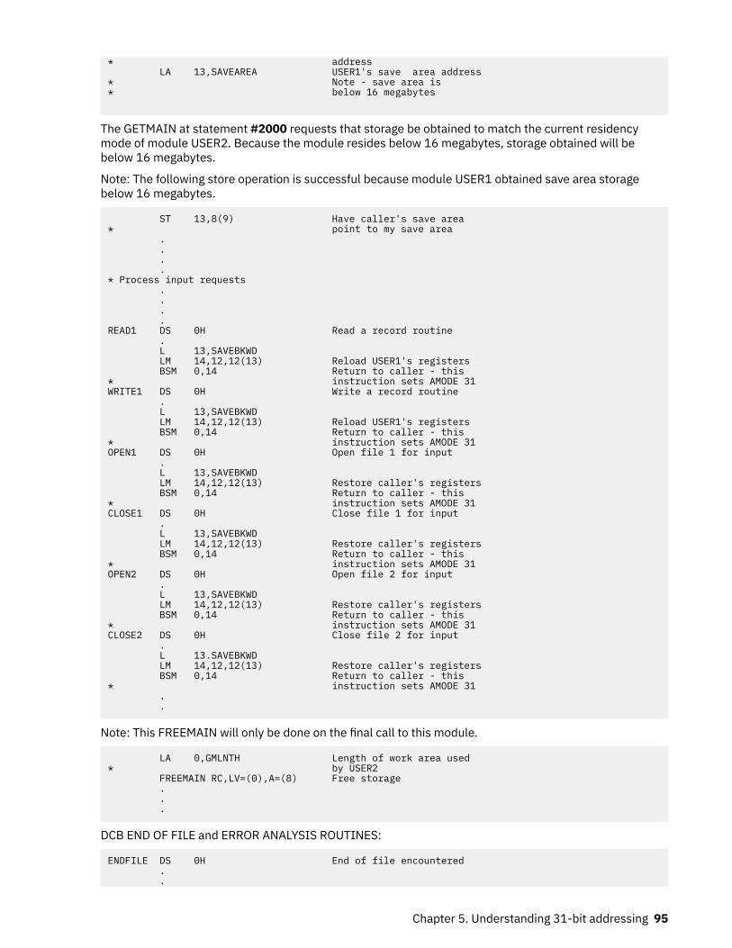
* address LA 13,SAVEAREA USER1's save area address* Note - save area is* below 16 megabytes
The GETMAIN at statement #2000 requests that storage be obtained to match the current residencymode of module USER2. Because the module resides below 16 megabytes, storage obtained will bebelow 16 megabytes.
Note: The following store operation is successful because module USER1 obtained save area storagebelow 16 megabytes.
ST 13,8(9) Have caller's save area* point to my save area . . . .* Process input requests . . . .READ1 DS 0H Read a record routine . L 13,SAVEBKWD LM 14,12,12(13) Reload USER1's registers BSM 0,14 Return to caller - this* instruction sets AMODE 31WRITE1 DS 0H Write a record routine . L 13,SAVEBKWD LM 14,12,12(13) Reload USER1's registers BSM 0,14 Return to caller - this* instruction sets AMODE 31OPEN1 DS 0H Open file 1 for input . L 13,SAVEBKWD LM 14,12,12(13) Restore caller's registers BSM 0,14 Return to caller - this* instruction sets AMODE 31CLOSE1 DS 0H Close file 1 for input . L 13,SAVEBKWD LM 14,12,12(13) Restore caller's registers BSM 0,14 Return to caller - this* instruction sets AMODE 31OPEN2 DS 0H Open file 2 for input . L 13,SAVEBKWD LM 14,12,12(13) Restore caller's registers BSM 0,14 Return to caller - this* instruction sets AMODE 31CLOSE2 DS 0H Close file 2 for input . L 13.SAVEBKWD LM 14,12,12(13) Restore caller's registers BSM 0,14 Return to caller - this* instruction sets AMODE 31 . .
Note: This FREEMAIN will only be done on the final call to this module.
LA 0,GMLNTH Length of work area used* by USER2 FREEMAIN RC,LV=(0),A=(8) Free storage . . .
DCB END OF FILE and ERROR ANALYSIS ROUTINES:
ENDFILE DS 0H End of file encountered . .
Chapter 5. Understanding 31-bit addressing 95

MVC STATUS,ENDFILE Indicate end of file to* module USER1 . L 13,SAVWBKWD LM 14,12,12(13) Reload USER1's registers BSM 0,14 Return to USER1* indicating end of file* has been encountered . . . .ERREXIT1 DS 0H SYNAD error exit one . . MVC STATUS,IOERROR Indicate I/O error to* module 'USER1' . L 13,SAVWBKWD LM 14,12,12(13) Reload USER1's registers BSM 0,14 Return to USER1* indicating an I/O error* has been encountered . . . .ERREXIT2 DS 0H SYNAD error exit two . . MVC STATUS,IOERROR Indicate I/O error to* module 'USER1' . L 13,SAVWBKWD LM 14,12,12(13) Reload USER1's registers BSM 0,14 Return to USER1* indicating an I/O error* has been encountered
Note: Define the required DCBs that module USER2 will process. The DCBs exist in storage below 16megabytes. The END OF DATA and SYNAD exit routines also exist in storage below 16 megabytes.
INDCB DCB DDNAME=INPUT1,DSORG=PS,MACRF=(GL),EODAD=ENDFILE, x SYNAD=ERREXIT1OUTDCB DCB DDNAME=OUTPUT1,DSORG=PS,MACRF=(PL),SYNAD=ERREXIT2* Work areas and constants for module USER2IOERROR DC C'IO' Constant used to indicate* an I/O errorENDFILE DC C'EF' Constant used to indicate* end of file encounteredSAVEREGS DSECT This storage exists* below 16 megabytesSAVEAREA EQU SAVEREGSSAVERSVD DS F ReservedSAVEBKWD DS FSAVEFRWD DS FSAVE1412 DS 15F Save area for registers 14-12WORKLNTH EQU *-SAVEREGS Length of dynamic area . . . . .COMMAREA DSECT Parameter area used to* communicate with module* USER1FUNCTION DS CL2 Function to be performed* by USER2STATUS DS CL2 Status of read operationBUFFER DS CL80 Input/output buffer . .DYNAREA DSECT This storage exists* below 16 megabytes . . . . . .
96 z/OS: z/OS MVS Assembler Services Guide

GMLNTH EQU *-DYNAREA Length of dynamic area . . END
Understanding the use of central storageMVS programs and data reside in virtual storage that, when necessary, is backed by central storage. Mostprograms and data do not depend on their real addresses. Some MVS programs, however, do depend onreal addresses and some require these real addresses to be less than 16 megabytes. MVS reserves asmuch central storage below 16 megabytes as it can for such programs and, for the most part, handlestheir central storage dependencies without requiring them to make any changes.
The system uses the area of central storage above 16 megabytes to back virtual storage with real frameswhenever it can. All virtual areas above 16 megabytes can be backed with real frames above 16megabytes. In addition, the following virtual areas below 16 megabytes can also be backed with realframes above 16 megabytes:
• SQA• LSQA• Nucleus• Pageable private areas• Pageable CSA• PLPA• MLPA• Resident BLDL
The following virtual areas are always backed with real frames below 16 megabytes:
• V=R regions• FLPA• Subpool 226• Subpools 227 and 228 (unless specified otherwise by the GETMAIN macro with the LOC parameter)
When satisfying page-fix requests, MVS backs pageable virtual pages that reside below 16 megabyteswith central storage below 16 megabytes, unless the GETMAIN macro specifies LOC=(24,31) or thePGSER macro specifies the ANYWHER parameter. If the GETMAIN or STORAGE macro specifies or impliesa real location of 31, MVS backs pageable virtual pages with real frames above 16 megabytes even whenthe area is page fixed.
Central storage considerations for user programsAmong the things to think about when dealing with central storage in 31-bit addressing mode are the useof the load real address (LRA) instruction, the use of the LOC parameter on the GETMAIN macro, thelocation of the DAT-off portion of the nucleus, and using EXCPVR to perform I/O. (EXCPVR was describedin the section Performing I/O in 31-Bit Addressing Mode.)
Load real address (LRA) instructionThe LRA instruction works differently depending on addressing mode you use. In 64-bit mode, the LRAinstruction results in a 64-bit real address stored in a 64-bit GPR. In 24-bit and 31-bit modes, the LRAinstruction results in a 31-bit real address stored in a 32-bit GPR. The LRA instruction cannot be used toobtain the real address of locations backed by real frames above 2 gigabytes in 24-bit or 31-bitaddressing mode. For those situations, use the LRAG instruction instead of LRA. All programs that issuean LRA instruction must be prepared to handle a 31-bit result if the virtual storage address specifiedcould have been backed with central storage above 16 megabytes, or a 64-bit result if the virtual storageaddress specified could have been backed with central storage above 2 gigabytes. Issue LRA only against
Chapter 5. Understanding 31-bit addressing 97

areas that are fixed. The TPROT instruction can be used to replace the LRA instruction when a program isusing it to verify that the virtual address is translatable and the page backing it is in real storage.
GETMAIN macroThe LOC parameter on the RU, RC, VRU, and VRC forms of the GETMAIN macro specifies not only thevirtual storage location of the area to be obtained, but also the central storage location when the storageis page fixed.
• LOC=24 indicates that the virtual storage is to be located below 16 megabytes. When the area is pagefixed, it is to be backed with central storage below 16 megabytes.
• LOC=(24,31) indicates that virtual storage is to be located below 16 megabytes but that central storagecan be located either above or below 16 megabytes, but below 2 gigabytes.
• LOC=(24,64) indicates that virtual storage is to be located below 16 megabytes but that central storagecan be located anywhere.
• LOC=31 and LOC=(31,31) indicate that both virtual and central storage can be located either above orbelow 16 megabytes, but below 2 gigabytes in central storage.
• LOC=(31,64) indicates that virtual storage is to be located below 2 gigabytes but that central storagecan be located anywhere.
• LOC=RES indicates that the location of virtual and central storage depends on the location (RMODE) ofthe GETMAIN issuer. If the issuer has an RMODE of 24, LOC=RES indicates the same thing as LOC=24; ifthe issuer has an RMODE of ANY, LOC=RES indicates the same thing as LOC=31.
• LOC=(RES,31) indicates that the location of virtual storage depends on the location of the issuer butthat central storage can be located anywhere below 2 gigabytes.
• LOC=(RES,64) indicates that the location of virtual storage depends on the location of the issuer butthat central storage can be located anywhere.
Note: There is exception to the meaning of LOC=RES and LOC=(RES,31). A caller residing below 16megabytes but running with 31-bit addressing can specify LOC=RES (either explicitly or by taking thedefault) or LOC=(RES,31) to obtain storage from a subpool supported only above 16 megabytes. In thiscase, the caller's AMODE determines the location of the virtual storage.
LOC is optional except in the following case: A program that resides above 16 megabytes and uses the RU,RC, VRU, and VRC forms of GETMAIN must specify either LOC=24 or LOC=(24,31) on GETMAIN requestsfor storage that will be used by programs running in 24-bit addressing mode. Otherwise, virtual storagewould be assigned above 16 megabytes and 24-bit addressing mode programs could not use it.
The location of virtual storage can also be specified on the PGSER (page services) macro. The ANYWHERparameter on PGSER specifies that a particular virtual storage area can be placed either above or below16 megabytes on future page-ins. This parameter applies to virtual storage areas where LOC=(24,31) orLOC=(31,31) was not specified on GETMAIN.
DAT-off routinesThe z/OS nucleus is mapped and fixed in central storage without attempting to make its virtual storageaddresses equal to its real addresses. Systems that use 31-bit addressing save a V=F (virtual=fixed)nucleus.
Because the z/OS nucleus is not V=R, the nucleus code cannot turn DAT-off and expect the nextinstruction executed to be the same as if DAT was on.
To allow for the execution of DAT-off nucleus code, the z/OS nucleus consists of two load modules, onethat runs with DAT on and one that runs with DAT off. Nucleus code that needs to run with DAT off mustreside in the DAT-off portion of the nucleus.
When the system is initialized, the DAT-off portion of the nucleus is loaded into the highest contiguouscentral storage. Therefore, you must modify any user modules in the nucleus that run with DAT off so thatthey operate correctly above 16 megabytes. Among the things you may have to consider are:
98 z/OS: z/OS MVS Assembler Services Guide

• All modules in the DAT-off portion of the nucleus have the attributes AMODE 31, RMODE ANY. They mayreside above 16 megabytes.
• These modules must return control via a BSM 0,14.• Register 0 must not be destroyed on return.
To support modules in the DAT-off nucleus:
• Move the DAT-off code to a separate module with AMODE 31, RMODE ANY attributes. Use as its entrypoint, IEAVEURn where n is a number from 1 to 4. (MVS reserves four entry points in the DAT-offnucleus for users.) Use BSM 0,14 as the return instruction. Do not destroy register 0.
• Code a DATOFF macro to invoke the DAT-off module:
DATOFF INDEX=INDUSRn
The value of n in INDUSRn must be the same as the value of n in IEAVEURn, the DAT-off module's entrypoint.
• Link edit the DAT-off module (IEAVEURn) into the IEAVEDAT member of SYS1.NUCLEUS (the DAT-offnucleus).
See z/OS MVS Programming: Authorized Assembler Services Guide and z/OS MVS Programming: AuthorizedAssembler Services Reference ALE-DYN for more information about modifying the DAT-off portion of thenucleus and the DATOFF macro.
Chapter 5. Understanding 31-bit addressing 99

100 z/OS: z/OS MVS Assembler Services Guide

Chapter 6. Resource control
When your program executes, other programs are executing concurrently in the MVS multiprogrammingenvironment. Each group of programs, including yours, is a competitor for resources available atexecution time. A resource is anything that a program needs as it executes — such as processor time, adata set, another program, a table, or a hardware device, etc. The competitor for resources is actually thetask that represents the program.
If you subdivide a program into separate logical parts, and code it as several small programs instead ofone large program, you can make the parts execute as separate tasks and with greater efficiency.However, you must ensure that each part executes in correct order relative to the others:
• The WAIT, POST, and EVENTS macros introduce a strategic delay in the running of a program. This delayforces a program to wait using an event control block (ECB), for a particular event to occur. When theevent occurs, the program can run once again. The event can be the availability of a necessary resource.
• Pause, Release, and Transfer are services you can call, using a pause element (PE), to synchronize taskprocessing with minimal overhead. Table 4 on page 101 compares the use of the Pause, Release, andTransfer services with the WAIT and POST macros.
• The ISGENQ macro allows your program to serialize resources by:
– Obtaining a single ENQ or multiple ENQs with or without associated device reserves.– Changing the control from shared to exclusive on one or more resources.– Releasing a single ENQs, or multiple ENQs.– Testing the availability of one or more resources.– Testing how the resource request would be altered by RNL processsing or dynamic global resource
serialization exits.
Note: As of z/OS Release 6, the ENQ, DEQ, and RESERVE interfaces will continue to be supported,though IBM recommends using the ISGENQ service for unauthorized serialization requests.
• The ISGQUERY macro allows you to obtain information about the use of resources.
Table 4. Task Synchronization Techniques
Pause, Release, and Transfer WAIT and POST
Can change the dispatchability of a task. Can change the dispatchability of a task.
Can release a task before it is paused. Can post a task before it waits.
An unauthorized caller can pause and release any taskin the caller's home address space.
An unauthorized caller can WAIT and POST any task inthe caller's home address space.
A task can pause multiple PEs at a time. When thespecified number of PEs has been released, the task ismade dispatchable.
A task may wait on multiple ECBs. If the wait countnumbers are posted, the task is made dispatchable.
The Transfer service can simultaneously pause onetask and release another.
There is no single service with comparable capabilityfor WAIT and POST.
The Transfer service can release a task andimmediately pass control to the released task.
There is no single service with comparable capabilityfor WAIT and POST.
The system ensures the Pause Elements are notreused improperly, thus avoiding improper releasescaused by unexpected termination or asynchronousABENDs.
© Copyright IBM Corp. 1988, 2020 101

Table 4. Task Synchronization Techniques (continued)
Pause, Release, and Transfer WAIT and POST
Ability to pass control directly from one task toanother paused task.
High performance. No local lock contentions effects. Lower performance, possible local lock contention.
Callers may use ECBLIST or EVENTS service to wait onmultiple ECBs.
Synchronizing tasks (WAIT, POST, and EVENTS macros)Some planning on your part is required to determine what portions of one task are dependent on thecompletion of portions of all other tasks. The POST macro is used to signal completion of an event; theWAIT and EVENTS macros are used to indicate that a task cannot proceed until one or more events haveoccurred. An event control block (ECB) is used with the WAIT, EVENTS or POST macros; it is a fullword ona fullword boundary, as shown in Figure 44 on page 102.
An ECB is also used when the ECB parameter is coded in an ATTACH or ATTACHX macro (see the z/OSMVS Programming: Assembler Services Reference ABE-HSP for information on how to use the ATTACH orATTACHX macro to create a new task and indicate the entry point in the program to be given control whenthe new task becomes active). In this case, the control program issues the POST macro for the event(subtask termination). Either the 24-bit (bits 8 to 31) return code in register 15 (if the task completednormally) or the completion code specified in the ABEND macro (if the task was abnormally terminated) isplaced in the ECB as shown in Figure 44 on page 102. The originating task can issue a WAIT macro orEVENTS macro with WAIT=YES parameter specifying the ECB; the task will not regain control until afterthe event has taken place and the ECB is posted (except if an asynchronous event occurs, for example,timer expiration).
Figure 44. Event Control Block (ECB)
When an ECB is originally created, bits 0 (wait bit) and 1 (post bit) must be set to zero. If an ECB is reused, bits 0 and 1 must be set to zero before a WAIT, EVENTS ECB= or POST macro can be specified. If,however, the bits are set to zero before the ECB has been posted, any task waiting for that ECB to beposted will remain in the wait state. When a WAIT macro is issued, bit 0 of the associated ECB is set to 1.When a POST macro is issued, bit 1 of the associated ECB is set to 1 and bit 0 is set to 0. For an EVENTStype ECB, POST also puts the completed ECB address in the EVENTS table.
A WAIT macro can specify more than one event by specifying more than one ECB. (Only one WAIT macrocan refer to an ECB at a time, however.) If more than one ECB is specified in a WAIT macro, the WAITmacro can also specify that all or only some of the events must occur before the task is taken out of thewait condition. When a sufficient number of events have taken place (ECBs have been posted) to satisfythe number of events indicated in the WAIT macro, the task is taken out of the wait condition.
An optional parameter, LONG=YES or NO, allows you to indicate whether the task is entering a long wait ora regular wait. A long wait should never be considered for I/O activity. However, you might want to use along wait when waiting for an operator response to a WTOR macro.
Through the LINKAGE parameter, POST and WAIT allow you to specify how the macro passes control tothe control program. You can specify that control is to be passed by an SVC or a PC instruction.
When you issue the WAIT or POST macro and specify LINKAGE=SVC (or use the default), your programmust not be in cross memory mode. The primary, secondary, and home address spaces must be thesame, your program must be in primary ASC mode, and it must not have an enabled unlocked task (EUT)
102 z/OS: z/OS MVS Assembler Services Guide

functional recovery routine (FRR) established. You may use WAIT and POST when the primary and thehome address spaces are different by specifying LINKAGE=SYSTEM. This option generates a PC interfaceto the WAIT or POST service and requires that the program be enabled, unlocked, in primary ASC modeand, for WAIT only, in task mode. For POST, the control program assumes that the ECB is in the primaryaddress space. For WAIT, it assumes that the ECB is in the home address space.
Figure 45 on page 103 shows an example of using LINKAGE=SYSTEM. The program that runs under TCB1in ASN1 PCs to a program in ASN2. Now the primary address space is ASN2 and home address space isASN1. When the PC routine posts ECB2, it uses LINKAGE=SYSTEM because home and primary aredifferent. The PC routine waits on ECB1 using LINKAGE=SYSTEM because home and primary are stilldifferent. Note that ECB1 is in the home address space.
Figure 45. Using LINKAGE=SYSTEM on the WAIT and POST Macros
Synchronizing tasks (Pause, Release, and Transfer)Pause, Release, and Transfer are callable services that enable you to synchronize task processing withminimal overhead. If you have, for example, an application that requires two or more tasks to tradecontrol back and forth, these services provide efficient transfers of control.
These services, which are available to both unauthorized and authorized callers in Assembler as well as Cor C++, use a system-managed object called a pause element to synchronize processing of tasks. Theservices provide the following functions:
Table 5. Pause, Release, and Transfer callable services
Callable service64-bit versioncallable service Description
IEAVAPE, IEAVAPE2 IEA4APE, IEA4APE2 Obtains a pause element token (PET), which uniquelyidentifies a pause element (PE).
IEAVDPE, IEAVDPE2 IEA4DPE, IEA4DPE2 Frees a pause element (PE) that is no longer needed.
IEAVPSE, IEAVPSE2 IEA4PSE, IEA4PSE2 Pauses the current task or SRB.
IEAVPME2 IEA4PME2 Pauses the current task or SRB using multiple PETs.
IEAVRLS, IEAVRLS2 IEA4RLS, IEA4RLS2 Releases a paused task or SRB.
IEAVRPI, IEAVRPI2 IEA4RPI, IEA4RPI2 Retrieves information about a pause element (PE).
IEAVTPE IEA4TPE Tests a pause element (PE) and determines its state.
Chapter 6. Resource control 103

Table 5. Pause, Release, and Transfer callable services (continued)
Callable service64-bit versioncallable service Description
IEAVXFR, IEAVXFR2 IEA4XFR, IEA4XFR2 Releases a paused task and, when possible, gives itimmediate control, while optionally pausing the task underwhich the Transfer request is made.
The services use a system-managed pause element (PE) rather than an application-managed controlblock, such as an event control block (ECB), thus reducing the possibility of error that might come fromimproper reuse of the control block.
As a PE is much like an ECB, the Pause service is much like the WAIT macro, and the Release service ismuch like the POST macro. Just as you can use POST to keep a task from waiting by preposting, you canuse Release to keep a task from pausing by prereleasing.
The Transfer service can both release a paused task and pass control directly to the released task. TheTransfer service can also pause the task that calls the service. Thus, Transfer enables quick dispatches,saving the overhead of work search. It also allows two tasks to trade control back and forth with minimaloverhead.
To understand how to use the services, you need to know more about pause elements, (PEs) and thepause element tokens (PETs) that identify them.
Pause elements and pause element tokensA pause element (PE) is a system-managed object used to pause and release a work unit, which can beeither a task or SRB. Like an ECB, a PE is used by the system to control whether or not a work unit isdispatchable. You can use a PE, like an ECB, to prerelease a work unit before it is paused. There are,however, significant differences between an ECB and a PE Table 6 on page 104 compares the two:
Table 6. Pause Element (PE) and Event Control Block (ECB)
Pause Element (PE) Event Control Block (ECB)
Managed by the system. Managed by application programs.
Identified by a pause element token (PET). Identified by a simple address.
Cannot be reused once invalidated by anasynchronous ABEND.
Can be reused after a task is removed from the waitstate by an asynchronous ABEND, although reuserequires very complicated programming.
To prevent errors related to reuse, a PET can be usedonly once to identify a PE. Once a task is paused andreleased, an updated PET is needed to identify the PE.The system returns the updated PET to the callerthrough the Pause or Transfer service.
There is no control on the reuse of an ECB; the sameECB address can be used over and over.
PEs are allocated and deallocated through calls tosystem services.
ECBs are allocated by application programs.
The total number of PEs available to all unauthorizedprograms in a system is limited to 130560.
The system imposes no limits on the number of ECBs.
PEs are not directly addressable through PETs. Theuser of a PE does not know its actual address andcannot modify it except through the use of systemservices.
ECBs can be modified at will by application programs.
104 z/OS: z/OS MVS Assembler Services Guide

A PE allocated by an unauthorized caller can be used to pause and release any work unit in the caller'shome address space. An unauthorized caller cannot pause or release using a PE allocated withauth_level=IEA_AUTHORIZED or pause_element_auth_level=IEA_AUTHORIZED.
When a PE is allocated with auth_level=IEA_AUTHORIZED (callable services IEAVAPE and IEA4APE) orpause_element_auth_level=IEA_AUTHORIZED (callable services IEAVAPE2 and IEA4APE2), the PE canbe used to pause and release any task or SRB in the system. The same PE can be used, for example, topause a task in address space 10. After being released, the same PE can be used to pause an SRB in, say,address space 23. There is, however, a small performance penalty imposed when a PE is used to pause atask or SRB in one space and then reused to pause a task or SRB in another space. This cost is accruedupon each space transition.
The following services (IEAVAPE2, IEAVDPE2, IEAVPME2, IEAVPSE2, IEAVRLS2, IEAVRPI2, IEAVXFR2,IEA4APE2, IEA4DPE2, IEA4PME2, IEA4PSE2, IEA4RLS2, IEA4RPI2, and IEA4XFR2) have a 'LINKAGE='keyword that specifies whether the caller is authorized (LINKAGE=BRANCH requires the caller to be inkey 0 supervisor state). The authorization of the PET is not specified, except when it is allocated via theIEAVAPE2 (or IEA4APE2) service. Instead, the authorization of the PET is implied. Authorized users canuse any PET, but unauthorized users only can use a PET that was allocated for unauthorized use.
When an authorized program is passed a PET from an unauthorized program, the authorized programmust ensure that the PET is valid to be used by the unauthorized program. The authorized program canvalidate this by invoking the IEAVRPI2 (or IEA4RPI2) service and specifying a special value for the linkageparameter. When an authorized program needs to validate that a PET can be used by an unauthorizedprogram, add IEA_UNTRUSTED_PET to the value specified for LINKAGE and invoke the IEAVRPI2 service.The data returned by the IEAVRPI2 service identifies whether the unauthorized caller is able to use thePET:
• Return_code must be 0.• Pause_element_auth_level must be IEA_PET_UNAUTHORIZED.
A PE can be used to pause only one task or SRB at a time; the system does not allow more then onedispatchable unit to be paused under a single PE.
Pause elements are not supported by checkpoint/restart. However, support has been added with APAROA19821 to permit the allocation of pause elements that can allow a successful checkpoint/restart. Thisis possible for applications that can tolerate the fact that the pause element will not be restored upon arestart after a checkpoint. An application can tell if this support is available by checking if CVTPAUS4 hasbeen set in the CVT. A new type is introduced for the auth_level parameter of the Allocate Pause Elementservice. The new level is created by adding the value of the new type (IEA_CHECKPOINTOK) to theexisting value (at one time, only IEA_AUTHORIZED or IEA_UNAUTHORIZED can be specified). Whenpause elements are allocated, a checkpoint is accepted only if all encountered pause elements have beenallocated indicating the IEA_CHECKPOINTOK type.
Using the servicesThere are 28 callable services available for task synchronization:
• Allocate_Pause_Element – IEAVAPE, IEAVAPE2, IEA4APE, or IEA4APE2• Deallocate_Pause_Element – IEAVDPE, IEAVDPE2, IEA4DPE, or IEA4DPE2• Pause – IEAVPSE, IEAVPSE2, IEA4PSE, or IEA4PSE2• Pause_Multiple_Elements– IEAVPME2 or IEA4PME2• Release – IEAVRLS, IEAVRLS2, IEA4RLS, or IEA4RLS2• Retrieve_Pause_Element_Information - IEAVRPI, IEAVRPI2, IEA4RPI, or IEA4RPI2• Test_Pause_Element - IEAVTPE or IEA4TPE• Transfer – IEAVXFR, IEAVXFR2, IEA4XFR, or IEA4XFR2
To use Pause, Release, and Transfer, a program must first allocate a PE by calling theAllocate_Pause_Element service. In response, the system allocates a PE and returns a pause elementtoken (PET) that identifies the pause element (PE).
Chapter 6. Resource control 105

You use the PET returned from Allocate_Pause_Element to identify the allocated PE until either:
• The PE has been used to pause (through Pause or Transfer) and release (through Release or Transfer) atask.
• A paused task has been released through an asynchronous ABEND.
When you are finished with the PE, call the Deallocate_Pause_Element service to return the PE to thesystem. If a task is asynchronously ABENDed while it is paused, the system itself invalidates the PE, and itcannot be reused for pause requests. Thus, return an invalidated PE to the system as soon as possible bya call to Deallocate_Pause_Element.
Though the PE remains allocated until you deallocate it, you can use a PET for only one pair of calls, whichresult in a pause and a release of a task. When you specify a PET on a successful call to the Pause serviceor to pause a task through a successful call to the Transfer service, the system invalidates the input PETand returns an updated PET to identify the PE. Use the updated PET to reuse the PE or to deallocate thePE.
Figure 46 on page 106 shows, in pseudocode, the sequence of calls to allocate a PE, pause the currenttask, release the task, and deallocate the PE.
/* Common variables */ | | Dcl PET char(16); | | Workunit #1 | Workunit #2 | /* Workunit #1 variables */ | /* Workunit #2 variables */ Dcl Auth1 fixed(32); | Dcl Auth2 fixed(32); Dcl RC1 fixed(32); | Dcl RC2 fixed(32); Dcl Updated_pet char(16); | Dcl RelCode char(3); Dcl RetRelCode char(3); | | Auth1 = IEA_UNAUTHORIZED; | Auth2 = IEA_UNAUTHORIZED; . | . . | . . | . /* Allocate a Pause Element */ | Call IEAVAPE (RC1,Auth1,PET); | | /* Pause Workunit #1 */ | Call IEAVPSE (RC1,Auth1,PET, | Updated_PET,RetRelCode); | |/*processing pauses until released*/ | RelCode = '123'; | /* Release Workunit #1 */ | Call IEAVRLS (RC2,Auth2,PET, . | RelCode); . | . | PET = UPET; | Call IEAVPSE (RC1,Auth1,PET); | Updated_PET,RetRelCode); | |/*processing pauses until released*/ | RelCode = '345'; . | /* Release Workunit #1 */ . | Call IEAVRLS (RC2,Auth2,PET, . | RelCode); /* Deallocate the pause element */ | Call IEAVDPE (RC1,Auth1, | Updated_PET) |
Figure 46. Pause and Release Example
The Pause, Release, and Transfer services also provide a release code field that programs can use tocommunicate, to indicate, for example, the reason for a release. The program that calls the Releaseservice can set a release code.
The release code is particularly useful when a task might be released before it is paused (prereleased).When a subsequent call to the Pause service occurs, the system does not pause the task; instead, itreturns control immediately to the calling program and provides the release code specified on the releasecall.
106 z/OS: z/OS MVS Assembler Services Guide

Figure 47 on page 107 shows, in pseudocode, the sequence of calls needed to allocate a PE, prerelease atask, and deallocate the PE.
/* Common variables */ | | Dcl PET char(16); | | Workunit #1 | Workunit #2 | /* Workunit #1 variables */ | /* Workunit #2 variables */ Dcl Auth1 fixed(32); | Dcl Auth2 fixed(32); Dcl RC1 fixed(32); | Dcl RC2 fixed(32); Dcl Updated_PET char(16); | Dcl RelCode char(3); Dcl RetRelCode char(3); | | Auth1 = IEA_UNAUTHORIZED; | | /* Allocate a Pause Element */ | Call IEAVAPE (RC1,Auth1,PET); | . | Auth2 = IEA_UNAUTHORIZED; . | RelCode ='123'; . | | /* Release Workunit #1 */ | Call IEAVRLS (RC2,Auth2,PET, | RelCode); /* Pause Workunit #1 */ | . Call IEAVPSE (RC1,Auth1,PET, | . Updated_PET,RetRelCode); | . |/*check release code and continue */ | . | . | . | /* Deallocate the pause element */ | Call IEAVDPE (RC1,Auth1, | Updated_PET); |
Figure 47. Release and Pause Example
If you make a release request (through Release or Transfer) specifying a PET that identifies a PE that hasnot yet been used to pause a task, the system marks the PE as a prereleased PE. If a program tries topause a task using a prereleased PE, the system returns control immediately to the caller; it does notpause the task. Instead, it resets the PE. As soon as a PE is reset, it can be reused for another Pause andRelease, but, as stated earlier, you use the returned updated PET for the next reused PE.
The Pause and Release services are very similar to the WAIT and POST macros, but the Transfer serviceprovides new function. You can use Transfer to either:
• Release a paused task and transfer control directly to the released task• Pause the current task, release a paused task, and transfer control directly to the released task
Figure 48 on page 108 shows an example of using the Transfer service to release a task without pausingthe current task.
Because the Transfer service can affect multiple units of work, using Transfer requires you to work withthree PETs:
1. The current pause element token (CurrentDuPet in Figure 48 on page 108) identifies the allocatedpause element that Transfer is to use to pause the current task (the caller of the Transfer service).When you do not need to pause the current task, you set this token to binary zeros, as shown in Figure48 on page 108.
2. The updated pause element token (UPET2 in Figure 48 on page 108), which the system returns whenyou specify a current pause element token. You need this updated token to reuse the pause elementon a subsequent Pause or Transfer or to deallocate the pause element. If you set the current token tobinary zeros, as done in Figure 48 on page 108, the contents of the updated pause element token arenot meaningful.
3. The target token (TargetDuPET in Figure 48 on page 108) identifies the allocated pause element thatTransfer is to use to release a task. In Figure 48 on page 108, it contains the PET that identifies the PEused to pause Workunit #1.
Chapter 6. Resource control 107

A current release code and a target release code are also available on the call to Transfer. Whether or noteach code contains valid data depends on conventions set by the different parts of your program.
/* Common variables */ | | Dcl PET char(16); | | Workunit #1 | Workunit #2 |/* Workunit #1 variables */ | /* Workunit #2 variables */ Dcl Auth1 fixed(32); | Dcl Auth2 fixed(32); Dcl RC1 fixed(32); | Dcl RC2 fixed(32); Dcl UPET1 char(16); | Dcl CurrentDuRelCode char(3); Dcl RetRelCode char(3); | Dcl CurrentDuPET char(16); . | Dcl UPET2 char(16); . | Dcl TargetDuPET char(16); . | Dcl TargetDuRelCode char(3);Auth1 = IEA_UNAUTHORIZED; |/* Allocate a Pause Element */ | Auth2 = IEA_UNAUTHORIZED; Call IEAVAPE (RC1,Auth1,PET); | . | ./* Pause Workunit #1 */ | . Call IEAVPSE (RC1,Auth1,PET,UPET1, | TargetDuRelCode = '123'; RetRelCode); | /* no pause-set token to zeros */ | CurrentDuPet =''B; | TargetDuPET = PET/*processing pauses until transfer*/ | | /* Transfer to Workunit #1 */ | Call IEAVXFR (RC2,Auth2, | CurrentDuPET,UPET2, | CurrentDuRelCode, | TargetDuPET, | TargetDuRelCode);/*processing continues */ | . | . /* Deallocate the Pause Element */ | . Call IEAVDPE (RC1,Auth1,UPET1); |
Figure 48. Transfer without Pause Example
Serializing access to resources (ISGENQ macro)When one or more programs using a serially reusable resource modify the resource, they must not use theresource simultaneously with other programs. Consider a data area in virtual storage that is being used byprograms associated with several tasks of a job step. Some of the programs are only reading records inthe data area; because they are not updating the records, they can access the data area simultaneously.Other programs using the data area, however, are reading, updating, and replacing records in the dataarea. Each of these programs must serially acquire, update, and replace records by locking out otherprograms. In addition, none of the programs that are only reading the records want to use a record thatanother program is updating until after the record has been replaced.
If your program uses a serially reusable resource, you must prevent incorrect use of the resource. Youmust ensure that the logic of your program does not require the second use of the resource beforecompletion of the first use. Be especially careful when using a serially reusable resource in an exit routine;because exit routines get control asynchronously with respect to your program logic, the exit routinecould obtain a resource already in use by the main program. When more than one task is involved, usingthe ISGENQ macro correctly can prevent simultaneous use of a serially reusable resource.
z/OS Automatic Tape Switching (ATS STAR) uses the ISGDGRSRES exit to add additional deviceinformation to the DISPLAY GRS command. For information and an example, see Providing ENQ resourceinformation on DISPLAY GRS command in z/OS MVS Programming: Authorized Assembler Services Guide.
The ISGENQ macro assigns control of a resource to the current task. The control program determines thestatus of the resource and does one of the following:
• If the resource is available, the control program grants the request by returning control to the activetask.
• If the resource has been assigned to another task, the control program delays assignment of control byplacing the active task in a wait condition until the resource becomes available.
108 z/OS: z/OS MVS Assembler Services Guide

• Passes back a return code indicating the status of the resource.• Abends the caller on unconditional requests that would otherwise result in a non-zero return code.
When the status of the resource changes so that the waiting task can get control, the task is taken out ofthe wait condition and placed in the ready condition.
Naming the resourceThe ISGENQ macro identifies the resource by qname, rname, and a scope value. The qname and rnameneed not have any relation to any actual name of the resource. The control program does not associate aname with an actual resource; it merely processes requests having the same qname, rname, and scope ona first-in, first-out basis. It is up to you to associate the names with the resource by ensuring that all usersof the resource use the same qname, rname, and scope value to represent the same resource. The controlprogram treats requests having different qname, rname, and scope combinations as requests for differentresources. Because the control program cannot determine the actual name of the resource from theqname, rname, and scope, a task could use the resource by specifying a different qname, rname, andscope combination or by accessing the resource without using ISGENQ. In this case, the control programcannot provide any protection.
In many cases it is impossible for you to determine what resources are being serialized by the resourceidentified by the QNAME and RNAME. As such, GRS provides the ISGDGRSRES installation exit to allowauthorized programs to add additional resource information on the DISPLAY GRS command. For moreinformation and an example, see Providing ENQ resource information on DISPLAY GRS command in z/OSMVS Programming: Authorized Assembler Services Guide.
Defining the scope of a resourceYou can request a scope of STEP, SYSTEM, SYSTEMS, or SYSPLEX value on the ISGENQ macro.
• Use a scope of STEP if the resource is used only in your address space. The control program uses theaddress space identifier to make your resource unique in case someone else in another address spaceuses the same qname and rname and a scope of STEP.
• Use a scope of SYSTEM if the resource is serialized across all address spaces in a system. For example,to prevent two jobs from using a named resource simultaneously, use SYSTEM.
• Use a scope of SYSTEMS or SYSPLEX if the resource is available to more than one system. All programsthat serialize on the resource must use the same qname and rname and a scope of SYSTEMS. Forexample, to prevent two processors from using a named resource simultaneously, use SYSTEMS orSYSPLEX.
Note: Note that the control program considers a resource with a SYSTEMS scope to be different from aresource represented by the same qname and rname but with a scope of STEP or SYSTEM.
Local and global resourcesThe ISGENQ macro recognize two types of resources: local resources and global resources.
A local resource is a resource identified on ISGENQ, ENQ or DEQ by a scope of STEP or SYSTEM. A localresource is recognized and serialized only within the requesting operating system. The local resourcequeues are updated to reflect each request for a local resource. If a system is not operating under globalresource serialization (that is, the system is not part of a global resource serialization complex), allresources requested are treated as local resources.
If a system is part of a global resource serialization complex, a global resource is either identified on theENQ or DEQ macro by a scope of SYSTEMS, or on the ISGENQ macro by a scope of SYSTEMS or SYSPLEX.
If your system is part of a global resource serialization complex, global resource serialization mightchange the scope value during its resource name list (RNL) processing. If the resource appears in theSYSTEM inclusion RNL, a resource with a scope of SYSTEM can have its scope converted to SYSTEMS orSYSPLEX. If the resource appears in the SYSTEMS or SYSPLEX exclusion RNL, a scope of SYSTEMS or
Chapter 6. Resource control 109

SYSPLEX can have its scope changed to SYSTEM. This procedure is described in Selecting the data sectionof z/OS MVS Planning: Global Resource Serialization.
Alternate serialization products have the ability to provide additional global resource serialization. Assuch, a resource may be local (SYSTEM scope) from a global resource serialization perspective butactually be globally managed by an alternate serialization product. See “Determining the resulting scope”on page 110 for more details.
You can request that global resource serialization keep the API specified scope through the RNLparameter on ISGENQ, ENQ and DEQ. The scope, which systems use to serialize a Global resource, andother attributes, can be altered by a combination of the RNLs, installations exits or alternate serializationproducts to allow the installation and alternate serialization products to manage the ENQ. SpecifyingRNL=NO on the API will ensure that no changes are made and that only GRS will manage the resourceamong the systems in the GRS complex.
Note: Certain ENQs should not be altered.
For more important information about when to use RNL=NO, see “Determining the resulting scope” onpage 110.
Determining the resulting scopeYou can determine the resulting scope of your ISGENQ request and what caused any scope change totake place by using one or both of the ISGQUERY and ISGENQ REQUEST=TEST services. Use theseservices to insure that the resulting scope is correct for the current configuration of your product. ForRNL=YES requests, the scope can change by the RNL or installation exit.
Note that alternate serialization products use installation exits to control the scope that global resourceserialization uses. For example, an alternate serialization product can extend the scope such that it wouldindicate to global resource serialization that the scope should be local so it could extend it to its globalscope. This scope might be larger or smaller than the global resource serialization complex. If theresource must, under all possible user configurations, always be serialized at the specified scope and fora SYSTEMS scope, the systems must all be within the GRS Complex and not at an extended, alternateserialization product level or cross GRS Complex level, then use RNL=NO to prevent the ENQ Resourcedomain from changing. See z/OS MVS Planning: Global Resource Serialization for more information onResource Name Lists and alternate serialization product.
To assist the installation with monitoring and possibly altering the scope of ENQs based on how theproduct is configured, document all resources that are serialized by ENQs and how changing their scopecan be used to have the resource domain match various configurations. For example:
• To allow the installation to have unique instances of the product, on a system basis, the system uniqueresources and associated ENQs with SCOPE=SYSTEM are required. For ENQs that are always issuedwith SCOPE=SYSTEMS, use RNL=YES and require the installation to exclude the ENQ from the GlobalENQ domain via RNLs so the SCOPE is changed to SYSTEM and does not interact with others ondifferent systems.
• For a resource that is always shared within a Sysplex regardless of possible configurations, indicate thatthe product specifies RNL=NO on GRS APIs in order to ensure that the scope is not altered and theresource domain is always within the GRS complex. This would always include the Sysplex that issuedthe ENQ request.
• To allow the installation to use to an alternate serialization product to create subsets of the productwithin the GRS complex or Sysplex. Similar to unique instances per system, provide a means of havingunique resources per product instance domain and use RNL=YES on ENQ related APIs.
• To allow the installation to extend the sharing of the resource between GRS Complex domains via analternate serialization product, use RNL=YES on ENQ related APIs and document any other relatedconfiguration requirements.
Check the following ISGQUERY output fields related to an ISGQUERY of the interested resource todetermine if its scope is global:
110 z/OS: z/OS MVS Assembler Services Guide

1. Is ISGYQUAARqxAltSerExtended on? This indicates that it is globally managed by an alternateserialization product.
2. Is ISGYQUAARSSCOPE=ISGYQUAA_kSYSTEMS or ISGYQUAA_kSYSPLEX on? This indicates that it isglobally managed by global resource serialization.
Use various fields within the ISGYQUAA mapping to determine what caused the scope to be altered.
Test the resulting scope of an ISGENQ REQUEST=TEST request for resource by checking the followingISGYENQ fields:
1. Is ISGYENQAAALTSEREXTENDED on? This indicates it is globally managed by an alternate serializationproduct.
2. Is ISGYENQAAFinalScope=ISGENQ_SYSTEMS on? This indicates that it is globally managed by globalresource serialization.
Use various fields within the ISGYENQ mapping to determine what caused the scope to be altered.
Requesting exclusive or shared controlOn ISGENQ, you specify either exclusive or shared control of a resource through the CONTROL parameter.
When your program has exclusive control of a resource, it is the only one that can use that resource; allother programs that issue ENQs for the resource (either for exclusive or shared control) must wait untilyour program releases the resource. If your program will change the resource, it should request exclusivecontrol.
When your program has shared control of a resource other programs can have concurrent use of theresource. If another program requests exclusive control over the resource during the time your programhas shared use of the resource, that program will have to wait until all the current users have released theresource. If your program will not change the resource, it should request shared control.
For an example of how the control program processes requests for exclusive and shared control of aresource, see “Processing the requests” on page 112.
Limiting concurrent requests for resourcesTo prevent any one job, started task, or TSO/E user from generating too many concurrent requests forresources, the control program counts and limits the number of ENQ requests in each address space.When a user issues an ENQ request, the control program increases the count of outstanding requests forthat address space by one and decreases the count by one when the user issues a DEQ request.
ENQ RET=TEST, RET=CHNG, and ISGENQ equivalents do not cause this count to increase because theydo not queue up a new request block. A GQSCAN resulting in a continuation TOKEN however, along withthe ISGQUERY equivalent, does cause to count to increase.
Prior to an abend, messages ISG368E and ISG369I monitor address spaces that are approaching therequest maximum. If a particular subsystem requires more ENQs than normal, use the ISGADMIN serviceto raise that subsystem's maximum for unauthorized and authorized requesters. As a temporaryworkaround, you can raise the overall system maximum by issuing the following commands:
• SETGRS ENQMAXA for authorized• SETGRS ENQMAXU for unauthorized
When the computed count reaches the threshold value or limit, the control program processessubsequent requests as follows:
• Unconditional requests are abnormally ended with a system code of X'538'.• Conditional requests are rejected and the user receives a return code of X'18'.• For ISGENQ, see the return code of X'C01' explained in ISGENQ — Global resource serialization ENQ
service in z/OS MVS Programming: Assembler Services Reference IAR-XCT.
Chapter 6. Resource control 111
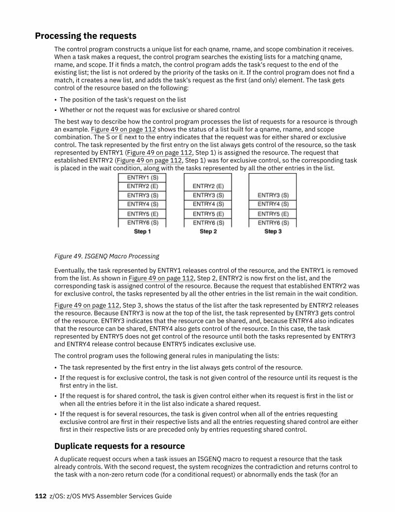
Processing the requestsThe control program constructs a unique list for each qname, rname, and scope combination it receives.When a task makes a request, the control program searches the existing lists for a matching qname,rname, and scope. If it finds a match, the control program adds the task's request to the end of theexisting list; the list is not ordered by the priority of the tasks on it. If the control program does not find amatch, it creates a new list, and adds the task's request as the first (and only) element. The task getscontrol of the resource based on the following:
• The position of the task's request on the list• Whether or not the request was for exclusive or shared control
The best way to describe how the control program processes the list of requests for a resource is throughan example. Figure 49 on page 112 shows the status of a list built for a qname, rname, and scopecombination. The S or E next to the entry indicates that the request was for either shared or exclusivecontrol. The task represented by the first entry on the list always gets control of the resource, so the taskrepresented by ENTRY1 (Figure 49 on page 112, Step 1) is assigned the resource. The request thatestablished ENTRY2 (Figure 49 on page 112, Step 1) was for exclusive control, so the corresponding taskis placed in the wait condition, along with the tasks represented by all the other entries in the list.
Figure 49. ISGENQ Macro Processing
Eventually, the task represented by ENTRY1 releases control of the resource, and the ENTRY1 is removedfrom the list. As shown in Figure 49 on page 112, Step 2, ENTRY2 is now first on the list, and thecorresponding task is assigned control of the resource. Because the request that established ENTRY2 wasfor exclusive control, the tasks represented by all the other entries in the list remain in the wait condition.
Figure 49 on page 112, Step 3, shows the status of the list after the task represented by ENTRY2 releasesthe resource. Because ENTRY3 is now at the top of the list, the task represented by ENTRY3 gets controlof the resource. ENTRY3 indicates that the resource can be shared, and, because ENTRY4 also indicatesthat the resource can be shared, ENTRY4 also gets control of the resource. In this case, the taskrepresented by ENTRY5 does not get control of the resource until both the tasks represented by ENTRY3and ENTRY4 release control because ENTRY5 indicates exclusive use.
The control program uses the following general rules in manipulating the lists:
• The task represented by the first entry in the list always gets control of the resource.• If the request is for exclusive control, the task is not given control of the resource until its request is thefirst entry in the list.
• If the request is for shared control, the task is given control either when its request is first in the list orwhen all the entries before it in the list also indicate a shared request.
• If the request is for several resources, the task is given control when all of the entries requestingexclusive control are first in their respective lists and all the entries requesting shared control are eitherfirst in their respective lists or are preceded only by entries requesting shared control.
Duplicate requests for a resourceA duplicate request occurs when a task issues an ISGENQ macro to request a resource that the taskalready controls. With the second request, the system recognizes the contradiction and returns control tothe task with a non-zero return code (for a conditional request) or abnormally ends the task (for an
112 z/OS: z/OS MVS Assembler Services Guide

unconditional request). You should design your program to ensure that a second request for a resourcemade by the same task is not issued as an unconditional request until control of the resource is releasedfor the first use. Be especially careful when using an ENQ macro in an exit routine.
Two specific reasons why the use of ISGENQ in an exit routine must be carefully planned are:
• The exit may be entered more than once for the same task.• An exit routine may request resources already obtained by some other process associated with the task.
For more information on this topic, see “ENQ and DEQ conditional and unconditional requests” on page113.
Releasing the resourceUse the RELEASE request to release a serially reusable resource that you obtained by using ISGENQmacro. If a task tries to release a resource which it does not control, the control program either returns anon-zero return code or abends the task. The control program might place many tasks in a wait conditionwhile it assigns control of the resource to one task. Having many tasks in the wait state might reduce theamount of work being done by the system, therefore, you should release the resource, so that anothertask can use it.
If a task terminates without releasing a resource, the control program releases the resourceautomatically. By default, outstanding ENQs have affinity to the task that issued the ENQ. The systemreleases any outstanding ENQs during termination as follows:
• Task termination: The user should provide a recovery routine to back out or complete any processingthat requires the serialization and then release any ENQs before the program gives up control. Thesystem automatically releases all of a task's outstanding ENQs after all recovery routines and taskrelated dynamic resources managers have executed.
• Memory termination: The system releases all ENQs during memory termination processing in caseswhere task related recovery and termination resource managers may not have run. The ENQs arereleased after all memory termination dynamic resource managers have executed.
Note that authorized routines that may get control under a resource manager must prevent themselvesfrom getting deadlocked. They may need to conditionally request an ENQ or query if it is alreadyoutstanding by the address space that is in memory termination. They cannot obtain nor release an ENQthat was obtained by the terminating space. However, they are guaranteed that no processing can takeplace in the space that is terminating. As such, they can use the outstanding serialization to perform anyrequired back out or completion processing.
ENQ and DEQ conditional and unconditional requestsUp to this point, only unconditional requests have been considered. You can, however, make conditionalrequests by using the COND parameter on ISGENQ and the RET parameter on the ENQ and DEQ macros.One reason for making a conditional request is to avoid the abnormal termination that occurs if you issuetwo ENQ macros for the same resource within the same task or when a DEQ macro is issued for aresource for which you do not have control.
See “ISGENQ conditional and unconditional requests” on page 114 for detailed information onconditional requests for ISGENQ.
The RET parameter of ENQ provides the following options:RET=TEST
Indicates the availability of the resource is to be tested, but control of the resource is not requested.RET=USE
Indicates control of the resource is to be assigned to the active task only if the resource isimmediately available. If any of the resources are not available, the active task is not placed in a waitcondition. When SYNCRES is enabled, the request is subject to a delay for the reserve even ifRET=USE is specified.
Chapter 6. Resource control 113

RET=CHNGIndicates the status of the resource specified is changed from shared to exclusive control.
RET=HAVEIndicates that control of the resource is requested conditionally; that is, control is requested only ifthe same task does not already have control of or an outstanding request for the same resource.
For the following descriptions, the term “active task” means the task issuing the ENQ macro. No referenceis intended to other tasks that might be active in other processors of a multiprocessor.
Use RET=TEST to test the status of the corresponding qname, rname, and scope combination, withoutchanging the list in any way or waiting for the resource. RET=TEST is most useful for determining if thetask already has control of the resource. It is less useful for determining the status of the list and takingaction based on that status. In the interval between the time the control program checks the status andthe time your program checks the return code and issues another ENQ macro, another task could havebeen made active, and the status of the list could have changed.
Use RET=USE if you want your task to receive control of the resource only if the resource is immediatelyavailable. If the resource is not immediately available, no entry will be made on the list and the task willnot be made to wait. RET=USE is most useful when there is other processing that can be done withoutusing the resource. For example, by issuing a preliminary ENQ with RET=USE in an interactive task, youcan attempt to gain control of a needed resource without locking your terminal session. If the resource isnot available, you can do other work rather than enter a long wait for the resource.
Use RET=CHNG to change a previous request from shared to exclusive control.
Use RET=HAVE to specify a conditional request for control of a resource when you do not know whetheryou have already requested control of that resource. If the resource is owned by another task, you will beput in a wait condition until the resource becomes available.
The RET=HAVE parameter on DEQ allows you to release control and prevents the control program fromabnormally ending the active task if a DEQ attempts to release a resource not held. If ENQ and DEQ areused in an asynchronous exit routine, code RET=HAVE to avoid possible abnormal termination.
ISGENQ conditional and unconditional requestsThe ISGENQ macro uses the COND keyword to determine if a request is conditional or unconditional. TheCOND keyword is set to either YES or NO. No is the default.
Use the following descriptions to guide your ISGENQ conditional requests.
Use REQUEST(OBTAIN) TEST(YES) to test the status of the corresponding qname, rname, and scopecombination. When you specify TEST(YES) on the OBTAIN request an answer area is mapped in ISGYENQ.The answer area can provide detailed information about the RNL and global resource serialization exitprocessing. When you use an answer area you must also indicate the length of the answer area throughthe ANSLEN keyword. Additionally, if a request already exists from the same task that matches thespecified resource, the ENQ token of that request will be returned.
Note: See ISGQUERY in z/OS MVS Programming: Assembler Services Reference IAR-XCTSEARCH=BY_ENQTOKEN to obtain information on a specific outstanding ENQ request. Both ISGQUERYand ISGENQ can be found in z/OS MVS Programming: Assembler Services Reference IAR-XCT.
Use REQUEST(OBTAIN) TEST(NO) CONTENTIONACT(FAIL) if you want your task to receive control of theresource only if the resource is immediately available. If the resource is not immediately available, noentry will be made on the list and the task will not be made to wait. This request is useful when there isother processing that can be done without using the resource. For example, by issuing a preliminaryISGENQ with CONTENTIONACT(FAIL) in an interactive task, you can attempt to gain control of a neededresource without locking your terminal session. If the resource is not available, you can do other workrather than enter a long wait for the resource. When SYNCRES is enabled, the request is subject to a delayfor the reserve even if CONTENTIONACT=FAIL is specified.
Use REQUEST(OBTAIN) TEST(NO) CONTENTIONACT(WAIT) to specify a conditional request for control ofa resource when you do not know whether you have already requested control of that resource. If the
114 z/OS: z/OS MVS Assembler Services Guide

resource is owned by another task, you will be put in a wait condition until the resource becomesavailable.
Use REQUEST(CHANGE) to change a previous request from shared to exclusive control.
Avoiding interlockAn interlock condition happens when two tasks are waiting for each other's completion, but neither taskcan get the resource it needs to complete. Figure 50 on page 115 shows an example of an interlock. TaskA has exclusive access to resource M, and task B has exclusive access to resource N. When task Brequests exclusive access to resource M, B is placed in a wait state because task A has exclusive controlof resource M.
The interlock becomes complete when task A requests exclusive control of resource N. The sameinterlock would have occurred if task B issued a single request for multiple resources M and N prior totask A's second request. The interlock would not have occurred if both tasks had issued single requestsfor multiple resources. Other tasks requiring either of the resources are also in a wait condition because ofthe interlock, although in this case they did not contribute to the conditions that caused the interlock.
Task A Task BENQ (M,A,E,8,SYSTEM) ENQ (N,B,E,8,SYSTEM) ENQ (M,A,E,8,SYSTEM)ENQ (N,B,E,8,SYSTEM)
Figure 50. Interlock Condition
This example involving two tasks and two resources is a simple example of an interlock. The examplecould be expanded to cover many tasks and many resources. It is imperative that you avoid interlock. Thefollowing procedures indicate some ways of preventing interlocks.
• Do not request resources that you do not need immediately. If you can use the serially reusableresources one at a time, request them one at a time and release one before requesting the next.
• Share resources as much as possible. If the requests in the lists shown in Figure 50 on page 115 hadbeen for shared control, there would have been no interlock. This does not mean you should share aresource that you will modify. It does mean that you should analyze your requirements for the resourcescarefully, and not request exclusive control when shared control is enough.
• If you need concurrent use of more than one resource, use the ENQ macro to request control of all suchresources at the same time. The requesting program is placed in a wait condition until all of therequested resources are available. Those resources not being used by any other program immediatelybecome exclusively available to the waiting program. For example, instead of coding the two ENQmacros shown in Figure 51 on page 115, you could code the one ENQ macro shown in Figure 52 on page115. If all requests were made in this manner, the interlock shown in Figure 50 on page 115 could notoccur. All of the requests from one task would be processed before any of the requests from the secondtask. The DEQ macro can release a resource as soon as it is no longer needed; multiple resourcesrequested in a single ENQ invocation can be released individually through separate DEQ instructions.
ENQ (NAME1ADD,NAME2ADD,E,8,SYSTEM)ENQ (NAME3ADD,NAME4ADD,E,10,SYSTEM)
Figure 51. Two Requests For Two Resources
ENQ (NAME1ADD,NAME2ADD,E,8,SYSTEM,NAME3ADD,NAME4ADD,E,10,SYSTEM)
Figure 52. One Request For Two Resources
• If the use of one resource always depends on the use of a second resource, then you can define the pairof resources as one resource. On the ENQ and DEQ macros, define the pair with a single rname andqname. You can use this procedure for any number of resources that are always used in combination.
Chapter 6. Resource control 115

However, the control program cannot then protect these resources if they are also requestedindependently. Any requests must always be for the set of resources.
• If there are many users of a group of resources and some of the users require control of a secondresource while retaining control of the first resource, it is still possible to avoid interlocks. In this case,each user should request control of the resources in the same order. For instance, if resources A, B, andC are required by many tasks, the requests should always be made in the order of A, B, and then C. Aninterlock situation will not develop, since requests for resource A will always precede requests forresource B.
• When multiple resources are ENQed, all users must acquire the resources in the same manner. If oneuser gets resources individually, all users must acquire the resources individually. If one user gets theresources through a single list, all users must acquire the resources in a single list, but the sequence ofresource names within the lists can be different.
Serializing access to resources through the ISGENQ macroIBM recommends using ISGENQ RESERVEVOLUME=NO, but you can also use ISGENQRESERVEVOLUME=YES or the RESERVE macro to serialize access when the following is true:
• The resource needs to be shared outside of the GRS complex. See z/OS MVS Planning: Global ResourceSerialization for more information about GRS Complexes and the use of RESERVE.
• Your installation is not using SMS to manage the shared data sets.
Obtaining a reserve increases the probability of contention for resources and the possibility of interlocks.If you use a reserve to serialize access to data sets on shared DASD, use ISGENQ REQUEST=RELEASE orthe DEQ macro to release the resource.
When different systems in your installation access data sets on shared DASD, you can specify the keywordRESERVEVOLUME=YES with a scope of SYSTEMS or SYSPLEX on the ISGENQ macro to serialize access tothose resources. That is, RESERVEVOLUME=YES is used when a hardware reserve is required to allowglobal resource serialization to share a DASD volume outside of the complex.
Collecting information about resources and their requestors(ISGQUERY and GQSCAN macros)
ISGQUERY is the IBM recommended replacement for the GQSCAN service.
Global resource serialization enables an installation to share symbolically named resources. Programsissue the ENQ and RESERVE macros to request access to resources; global resource serialization addsinformation about each requestor to the appropriate resource queue. The only way you can extractinformation from the resource queues is by using the ISGQUERY or GQSCAN macro.
The ISGQUERY macro allows you to obtain information about the status of each resource identified toglobal resource serialization, which includes information about the tasks that have requested theresource. ISGQUERY fully supports 64-bit callers.
How ISGQUERY returns resource informationUsing ISGQUERY the system returns information you request about the status of each resource identifiedto global resource serialization, which includes information about the tasks that have requested theresource. ISGQUERY fully supports 64-bit callers. Use the ISGQUERY service to inquire about:
• A particular scope of resources (such as STEP, SYSTEM, or SYSTEMS).• A specific resource by name.• A specific system or systems resource.• A specific address space resource.• Resources that are requested through the RESERVE macro.
116 z/OS: z/OS MVS Assembler Services Guide

The system collects the information you request from the resource queues and consolidates thatinformation before returning it. The ISGQUERY service returns the following types of global resourceserialization information:
• REQINFO=RNLSEARCH: To determine if a given resource name is in the current Resource Name Lists(RNL).
• REQINFO=ENQSTATS: To obtain information related to ENQ counts.• REQTYPE=QSCAN: To obtain information on resources and requesters of outstanding ENQ requests.• REQINFO=LATCHECA: To obtain enhanced contention analysis data for latch waiters that might
indicate contention issues.• REQINFO=USAGESTATS: To obtain information for address space level contention information related
to ENQs (all scopes) and latches (all latch sets).
See z/OS MVS Programming: Assembler Services Reference IAR-XCT for additional information.
How GQSCAN returns resource informationUsing GQSCAN, you can inquire about a particular scope of resources (such as STEP, SYSTEM, orSYSTEMS), a specific resource by name, a specific system's resources, a specific address space'sresources, or resources requested through the RESERVE macro. The system collects the information yourequest from the resource queues and consolidates that information before returning it. The informationreturned might not reflect changes in the resource queue that occur while the system collects theinformation.
The system returns the information you request in an area whose location and size you specify using theAREA parameter. The size of the area, the scope of the resource, and whether you code the TOKENparameter determine the information you receive from GQSCAN. Use the TOKEN parameter when youdesign your program to issue repeated calls to GQSCAN for the same request. For example, if you requestinformation about a resource that is shared across systems, the amount of information might be morethan will fit in the area that you provide. Using the TOKEN parameter allows you to issue subsequent callsto receive additional information about that resource.
GQSCAN returns the information in the form of resource information blocks (RIB) and resourceinformation block extensions (RIBE), as shown in the following figure. The RIB and the RIBE are describedin z/OS MVS Data Areas in the z/OS Internet library (www.ibm.com/servers/resourcelink/svc00100.nsf/pages/zosInternetLibrary).
In the RIB, the following fields contain information on RIBEs:
• RIBTRIBE contains the total number of RIBEs associated with this RIB.
Chapter 6. Resource control 117

• RIBNRIBE contains the total number of RIBEs associated with this RIB that GQSCAN could fit into thearea specified on the AREA parameter.
• RIBEDEVN contains a 4-digit EBCDIC device number for RESERVEs issued on the system. For RESERVEsissued on other systems, RIBEDEVN contains zero.
If the value in RIBNRIBE is less than the value in RIBTRIBE, you may need to specify a larger area withthe AREA parameter.
The number of RIBs and RIBEs you receive for a particular resource depends on the size of the area youprovide, and the scope and token values you specify on the GQSCAN macro.
How area size determines the information GQSCAN returnsThe size of the area you provide must be large enough to hold one RIB and at least one of its associatedRIBEs; otherwise, you might lose information about resource requestors, or you might have to callGQSCAN repeatedly to receive all of the information you requested. To determine whether you havereceived all RIBEs for a particular RIB, check the values in the RIBTRIBE and RIBNRIBE fields. Todetermine whether you have received all of the information on the resource queue, check the return codefrom GQSCAN.
IBM recommends that you use a minimum area size of 1024 bytes.
The information that GQSCAN returns in the area also depends on what values you specify for the SCOPEand TOKEN parameters.
How scope and token values determine the information GQSCAN returnsTable 7 on page 118 summarizes the possible values and the information returned for a GQSCAN request.
Table 7. GQSCAN Results with a Scope of STEP, SYSTEM, SYSTEMS, or ALL
GQSCAN Invocation TOKEN ParameterCoded?
Information Returned
Initial call No At least the first RIB that represents the first requestoron the resource queue, and as many of that RIB'sassociated RIBEs as will fit. Any RIBEs that do not fit arenot returned to the caller.
If all of the RIBEs fit, GQSCAN returns the next RIB onthe resource queue, as long as the remaining area islarge enough to hold that RIB and at least one of itsRIBEs.
Initial call Yes; value is zero At least the first RIB that represents the first requestoron the resource queue, and as many of that RIB'sassociated RIBEs as will fit. Any RIBEs that do not fit arenot returned to the caller.
If all of the RIBEs fit, GQSCAN returns the next RIB onthe resource queue, as long as the remaining area islarge enough to hold that RIB and all of its RIBEs.
Subsequent call No At least the first RIB that represents the first requestoron the resource queue, and as many of that RIB'sassociated RIBEs as will fit. Any RIBEs that do not fit arenot returned to the caller.
If all of the RIBEs fit, GQSCAN returns the next RIB onthe resource queue, as long as the remaining area islarge enough to hold that RIB and at least one of itsRIBEs.
118 z/OS: z/OS MVS Assembler Services Guide

Table 7. GQSCAN Results with a Scope of STEP, SYSTEM, SYSTEMS, or ALL (continued)
GQSCAN Invocation TOKEN ParameterCoded?
Information Returned
Subsequent call Yes; value is thetoken value returnedby GQSCAN on thepreceding call
At least the next RIB on the resource queue, with asmany of that RIB's associated RIBEs as will fit. AnyRIBEs that do not fit are not returned to the caller.
If all of the RIBEs fit, GQSCAN returns the next RIB onthe resource queue, as long as the remaining area islarge enough to hold that RIB and all of its RIBEs.
The example in Figure 53 on page 119 shows the area contents for three requests. For each request, thecaller specified the TOKEN parameter and one of the following for the scope value: STEP, SYSTEM,SYSTEMS, or ALL. Assume that the resource queue contains information about four resources: A, whichhas three requestors; B, which has six; C, which has two; and D, which has one.
Figure 53. Work Area Contents for GQSCAN with a Scope of STEP, SYSTEM, SYSTEMS, or ALL
Note that, because the specified area is not large enough, the caller cannot receive all of the RIBEsassociated with resource B, even though the caller coded the TOKEN parameter. To receive all of thoseRIBEs, the caller has to specify a larger area and reissue the GQSCAN request.
When scanning the information returned, you must use the size of the fixed portion of the RIB and theRIBE that is returned in register 0. The size of the fixed portion of the RIB (RIBLEN) is in the high-orderhalf of register 0, and the size of the RIBE (RIBELEN) is in the low-order half.
The first RIB starts at the beginning of the workarea you specify on the AREA parameter. To find the firstRIBE, add the value of RIBLEN and the variable portion of RIB (as found in the RIBVLEN field of the RIB)to the address of the workarea. To find the second RIBE, add the value of RIBELEN to the address of thefirst RIBE.
To find the second RIB, add the following to the location of the first RIB:
RIBLEN + RIBVLEN + (the number of RIBEs × RIBELEN)
How GRS determines the scope of an ENQ or RESERVE requestGlobal resource serialization may change the scope of an ENQ or RESERVE request that was issued with aSCOPE of SYSTEM or SYSTEMS (unless the request specified RNL=NO).
If an ENQ is issued with a scope of SYSTEM, and matches an entry in the SYSTEM inclusion RNL but doesnot match an entry in the SYSTEMS exclusion RNL, then global resource serialization changes the scope of
Chapter 6. Resource control 119

the request from SYSTEM to SYSTEMS (and processes the resource as a global resource). A GQSCAN withSCOPE=SYSTEM will not find a match on such a request.
If an ENQ or RESERVE is issued with a scope of SYSTEMS, and either it matches an entry in the SYSTEMSexclusion RNL, or the system is running with GRSRNL=EXCLUDE, then GRS changes the scope of therequest from SYSTEMS to SYSTEM (and processes the resource as a local resource). A GQSCAN withSCOPE=SYSTEMS will not find a match on such a request.
When issuing a GQSCAN for a resource whose scope might have been changed, you might find it desirableto specify SCOPE=ALL in order to match requests whether or not they have been changed.
120 z/OS: z/OS MVS Assembler Services Guide

Chapter 7. Program interruption services
Some conditions encountered in a program cause a program interruption. These conditions includeincorrect parameters and parameter specifications, as well as exceptional results, and are knowngenerally as program exceptions. The program status word's (PSW) program mask provide bits to controlcertain program exceptions. When MVS gives control to programs, these bits are usually off, disabling theprogram exceptions. However, MVS also provides the ESPIE and SPIE services to enable programexceptions and to allow a user exit routine to receive control when those exceptions occur. This chapterdescribes the use of ESPIE and SPIE services.
Specifying user exit routinesBy issuing the SPIE1 or ESPIE macro, you can specify your own exit routine to be given control for one ormore types of program exceptions. If you issue an ESPIE macro, you can also pass the address of aparameter list to the exit routine. When one of the specified program exceptions occurs in a problem stateprogram being executed in the performance of a task, the exit routine receives control in the key of theactive task and in the addressing mode in effect when the SPIE or ESPIE was issued. (If a SPIE macro wasissued, this is 24-bit addressing mode.)
For other program interruptions, the recovery termination manager (RTM), gets control.
If the SPIE or ESPIE macro specifies an exception for which the interruption has been disabled, thesystem enables the interruption when the macro is issued.
If a program interruption occurs, the exit routine receives control on interrupt codes 0 through F. For theSPIE macro, the exit routine receives control only if the interrupted program is in primary address spacecontrol (ASC) mode. For the ESPIE macro, the exit routine receives control if the interrupted program is ineither primary or access register (AR) ASC mode. For both the SPIE and ESPIE macros, the exit routinereceives control only for interrupts that occur when the primary, home, and secondary address spaces arethe same.
The environment established by an ESPIE macro exists for the entire task, until the environment ischanged by another SPIE/ESPIE macro, or until the program creating the ESPIE returns. Each succeedingSPIE or ESPIE macro completely overrides specifications in the previous SPIE or ESPIE macro. You canintermix SPIE and ESPIE macros in one program. Only one SPIE or ESPIE environment is active at a time.If an exit routine issues an ESPIE macro, the new ESPIE environment does not take effect until the exitroutine completes.
The system automatically deletes the SPIE/ESPIE exit routine when the request block (RB) thatestablished the exit terminates. If a caller attempts to delete a specific SPIE/ESPIE environmentestablished under a previous RB, the caller is abended with a system completion code of X'46D'. A callercan delete all previous SPIE and ESPIE environments (regardless of the RB under which they wereestablished) by specifying a token of zero with the RESET option of the ESPIE macro or an exit address ofzero with the SPIE macro.
A program, executing in either 24-bit or 31-bit addressing mode in the performance of a task, can issuethe ESPIE macro. If your program is executing in 31-bit addressing mode, you cannot issue the SPIEmacro. The SPIE macro is restricted in use to callers executing in 24-bit addressing mode in theperformance of a task. The following topics describe how to use the SPIE and ESPIE macros.
Using the SPIE macroThe program interruption control area (PICA) and the program interruption element (PIE) contain theinformation that enables the system to intercept user-specified program interruptions established usingthe SPIE macro. You can modify the contents of the active PICA to change the active SPIE environment.The PICA and the PIE are described in the following topics.
1 The ESPIE macro is the preferred programming interface.
© Copyright IBM Corp. 1988, 2020 121

Program interruption control areaThe expansion of each standard or list form of the SPIE macro contains a system parameter list called theprogram interruption control area (PICA). The PICA contains the new program mask for the interruptiontypes that can be disabled in the PSW, the address of the exit routine to be given control when one of thespecified interruptions occurs, and a code for interruption types (exceptions) specified in the SPIE macro.For the mapping provided by the IHAPICA mapping macro, see PICA in z/OS MVS Data Areas in the z/OSInternet library (www.ibm.com/servers/resourcelink/svc00100.nsf/pages/zosInternetLibrary).
The system maintains a pointer (in the PIE) to the PICA referred to by the last SPIE macro executed. ThisPICA might have been created by the last SPIE or might have been created previously and referred to bythe last SPIE. Before returning control to the calling program or passing control to another programthrough an XCTL or XCTLX macro, each program that issues a SPIE macro must cause the system toadjust the SPIE environment to the condition that existed previously or to eliminate the SPIE environmentif one did not exist on entry to the program. When you issue the standard or execute form of the SPIEmacro to establish a new SPIE environment, the system returns the address of the previous PICA inregister 1. If no SPIE/ESPIE environment existed when the program was entered, the system returnszeroes in register 1.
You can cancel the effect of the last SPIE macro by issuing a SPIE macro with no parameters. This actiondoes not reestablish the effect of the previous SPIE; it does create a new PICA that contains zeroes, thusindicating that you do not want an exit routine to process interruptions. You can reestablish any previousSPIE environment, regardless of the number or type of subsequent SPIE macros issued, by using theexecute form of the SPIE specifying the PICA address that the system returned in register 1. The PICAwhose address you specify must still be valid (not overlaid). If you specify zeroes as the PICA address, theSPIE environment is eliminated.
Figure 54 on page 122 shows how to restore a previous PICA. The first SPIE macro designates an exitroutine called FIXUP that is to be given control if fixed-point overflow occurs. The address returned inregister 1 is stored in the fullword called HOLD. At the end of the program, the execute form of the SPIEmacro is used to restore the previous PICA.
. . SPIE FIXUP,(8) Provide exit routine for fixed-point overflow ST 1,HOLD Save address returned in register 1 . . L 5,HOLD Reload returned address SPIE MF=(E,(5)) Use execute form and old PICA address . .HOLD DC F'0'
Figure 54. Using the SPIE Macro
Program interruption elementThe first time you issue a SPIE macro during the performance of a task, the system creates a programinterruption element (PIE) in the virtual storage area assigned to your job step. The system also creates aPIE whenever you issue a SPIE macro and no PIE exists. For the format of the PIE, see z/OS MVS DataAreas in the z/OS Internet library (www.ibm.com/servers/resourcelink/svc00100.nsf/pages/zosInternetLibrary).
The PICA address in the PIE is the address of the program interruption control area used in the lastexecution of the SPIE macro for the task. When control is passed to the routine indicated in the PICA, theESA/390 (basic control) mode old program status word contains the interruption code in bits 16-31 (thefirst byte is the exception extension code and the second is the exception code); you can test these bits todetermine the cause of the program interruption. See z/Architecture Principles of Operations SA22–7832for an explanation of the format of the old program status word. The system stores the contents ofregisters 14, 15, 0, 1, and 2 at the time of the interruption as indicated.
122 z/OS: z/OS MVS Assembler Services Guide

Using the ESPIE macroThe ESPIE macro extends the functions of the SPIE macro to callers in 31-bit addressing mode. Theoptions that you can specify using the ESPIE macro are:
• SET to establish an ESPIE environment (that is, specify the interruptions for which the user-exit routinewill receive control)
• RESET to delete the current ESPIE environment and restore the SPIE/ESPIE environment specified• TEST to determine the active SPIE/ESPIE environment
If you specify ESPIE SET, you pass the following information to the system:
• A list of the program interruptions to be handled by the exit routine• The location of the exit routine• The location of a user-defined parameter list
The system returns either a token representing the previously active SPIE or ESPIE environment, or atoken of zeroes if there was none.
If you code ESPIE RESET, you pass the token, which was returned when the ESPIE environment wasestablished, back to the system. The SPIE or ESPIE environment corresponding to the token is restored. Ifyou pass a token of zero with RESET, all SPIE and ESPIE environments are deleted. ESPIE RESET must notbe issued from an ESPIE exit. To remove the current ESPIE exit, set the EPIEPERC bit and specify theRESET token in EPIETOK. See “Requesting percolation from an ESPIE exit” on page 125 for moreinformation.
If you specify ESPIE TEST, you will be able to determine the active SPIE or ESPIE environment. ESPIETEST sets return codes to indicate which type of exit is active, if any, and if one or the other is active,provides information about the exit in a parameter list. Refer to the TEST parameter on the ESPIE macrofor a description of the return codes, and the information that is returned in the parameter list.
If an ESPIE environment is active and you issue a SPIE macro to specify interruptions for which a SPIEexit routine is to receive control, the system returns the address of a system-generated PICA in register 1.Do not modify the contents of the system-generated PICA; use the address to restore the previous ESPIEenvironment.
For a data exception,an ESPIE routine will receive the DXC value in its parameter area, and should use thisvalue rather than the value in the Floating Point Control (FPC) register.
If a retry is to be done, an ESPIE routine can manually change the value(s) of the FPR(s) and FPC register.Changes to the non-volatile fields (i.e., the IEEE settings) in the FPC register must be made carefully sincethis could affect the processing of the rest of the current program, and possibly subsequent programs.
The extended program interruption element (EPIE)The system creates an EPIE the first time you issue an ESPIE macro during the performance of a task orwhenever you issue an ESPIE macro and no EPIE exists. The EPIE is freed when you eliminate the ESPIEenvironment.
The EPIE contains the information that the system passes to the ESPIE exit routine when it receivescontrol after a program interrupt. When the exit routine receives control, register 1 contains the addressof the EPIE. (See the topic “Environment upon entry to user's exit routine” on page 123 for the contents ofthe other registers.) The format of the EPIE is shown in z/OS MVS Data Areas in the z/OS Internet library(www.ibm.com/servers/resourcelink/svc00100.nsf/pages/zosInternetLibrary).
Environment upon entry to user's exit routineWhen control is passed to your routine, the register contents are as follows:Register 0:
Used as a work register by the system.
Chapter 7. Program interruption services 123

Register 1:Address of the PIE or EPIE for the task that caused the interruption.
Registers 2-13:Unchanged.
Register 14:Return address.
Register 15:Address of the exit routine.
The access registers and linkage stack have the values that were current at the time of the programinterruption. Both SPIE and ESPIE exits always receive control in primary ASC mode.
The SPIE or ESPIE routine must maintain the return address supplied in GPR 14. The routine does nothave to place any information in any of the return registers for use by the system.
Functions performed in user exit routinesYour exit routine must determine the type of interruption that occurred before taking corrective action.Determining the type of interruption depends on whether the exit is associated with an ESPIE or a SPIEmacro.
• For an ESPIE, your exit routine can check the two-byte interruption code (the first byte is the exceptionextension code and the second is the exception code) in the second halfword of the EPIEINT field in theEPIE.
• For a SPIE, your exit routine can test bits 16 through 31 (the first byte is the exception extension codeand the second is the exception code) of the old program status word (OPSW in ESA/390 mode) in thePIE.
Note: For both ESPIE and SPIE – If you are using vector instructions and an exception of 8, 12, 13, 14, or15 occurs, your exit routine can check the exception extension code (the first byte of the two-byteinterruption code in the EPIE or PIE) to determine whether the exception was a vector or scalar type ofexception.
For more information about the exception extension code, see IBM System/370 Vector Operations.
Your exit routine can alter the contents of the registers when control is returned to the interruptedprogram. The procedure for altering the registers also depends on whether the exit is associated with anESPIE or a SPIE.
• For an ESPIE exit, the exit routine can alter the contents of general purpose and access registers 0through 15 in the save area in the EPIE.
• For a SPIE exit, the exit routine can alter general purpose registers 14 through 2 in the register savearea in the PIE. To change registers 3 through 13, the exit routine must alter the contents of theregisters themselves.
The exit routine can also alter the last four bytes of the OPSW in the PIE or EPIE. For an ESPIE, the exitroutine alters the condition code and program mask starting at the third byte in the OPSW. By changingthe OPSW, the routine can select any return point in the interrupted program. In addition, for ESPIE exits,the routine must set the AMODE bit of this four-byte address to indicate the addressing mode of theinterrupted program.
ESPIE exit routines can alter the ASC mode when control is returned to the interrupted program if theEPIEVERS field in the EPIE contains a value greater than zero. This value is set by the system. To alter theASC mode of the interrupted program, the exit must do the following:
• Set bit 17 of the EPIEPSW field in the EPIE. If this bit is 0 when control is returned to the interruptedprogram, the program receives control in primary ASC mode. If this bit is 1 when control is returned tothe interrupted program, the program receives control in AR ASC mode.
• Set the EPIERCTL bit in the EPIE to indicate that the ASC mode for the interrupted program has been setby the exit routine.
124 z/OS: z/OS MVS Assembler Services Guide

Requesting percolation from an ESPIE exitESPIE exits can request percolation of a program exception to the recovery termination manager (RTM)instead of returning control to the interrupted program.
If an ESPIE exit determines that a program exception must be handled by RTM, the ESPIE exit can turn onthe EPIEPERC bit to request that the exception be passed to RTM for normal recovery processing. Whenan ESPIE exit requests percolation, RTM converts the program exception to an abend code (for example,PIC 1 becomes abend 0C1) and passes control to ESTAE-type recovery routines.
Note: When the EPIEPERC bit is set, the ESPIE exit routine must not modify the PSW and registers in theEPIE.
When functional recovery routines (FRR) and ESTAE-type recovery routines percolate, the system deletesthe exit routines. When an ESPIE exit percolates, the ESPIE exit remains active and is not deleted. Torequest that the ESPIE exit is deleted when it percolates, set the EPIERSET bit and optionally specify aRESET TOKEN in the EPIERTOK field.
Note: ESPIE exits must not issue ESPIE RESET.
Chapter 7. Program interruption services 125

126 z/OS: z/OS MVS Assembler Services Guide

Chapter 8. Providing recovery
In an ideal world, the programs you write would run perfectly, and never encounter an error, eithersoftware or hardware. In the real world, programs do encounter errors that can result in the prematureend of the program's processing. These errors could be caused by something your program does, or theycould be beyond your program's control.
MVS allows you to provide something called recovery for your programs; that means you can anticipateand possibly recover from software errors that could prematurely end a program. To recover from theseerrors, you must have one or more user-written routines called recovery routines. The general idea isthat, when something goes wrong, you have a recovery routine standing by to take over, fix the problem,and return control to your program so that processing can complete normally; if the problem cannot befixed, the recovery routine would provide information about what went wrong. If correctly set up, yourrecovery should, at the very least, provide you with more information about what went wrong with yourprogram than you would have had otherwise.
Part of recovery is also the "cleaning up" of any resources your program might have acquired. By "cleanup" of resources, we mean that programs might need to release storage that was obtained, release ENQs,close data sets, and so on. If your program encounters an error before it has the opportunity to clean upresources, your recovery routine can do the clean up.
MVS provides the recovery termination manager (RTM) to handle the process by which recovery routinesand resource managers receive control.
This chapter is devoted to explaining why you might want to provide recovery for your programs inanticipation of encountering one or more errors, and how you go about doing that. An important point tonote is that providing recovery is something to be considered at the design stage of your program. Youshould make the decision about whether to provide recovery before you begin designing the program.Trying to provide recovery for an existing program is much more difficult because recovery must be anintegral part of your program.
The following table provides a roadmap to the information in this chapter. If you already understandrecovery concepts, you might want to skip directly to those topics of specific interest to you.
To find out about: Consult the following topic:
General recovery concepts, including:
• Why you would want to provide recovery.• What software errors result in your recovery
getting control.• What we mean when we say a program
abnormally ends.• The different states for a recovery routine.• The different types of routines in a recovery
environment, and how to choose, define, andactivate the right recovery routine.
• The basic options available to a recovery routine.• How routines in a recovery environment interact.
“Understanding general recovery concepts” onpage 128.
© Copyright IBM Corp. 1988, 2020 127

To find out about: Consult the following topic:
How to write a recovery routine, including:
• What recovery routines do.• How recovery routines communicate with other
routines and with the system.• Special considerations when writing different
types of recovery routines.
“Writing recovery routines” on page 135.
The recovery environment, including:
• Register contents at various times duringrecovery processing.
• Other environmental factors such as programauthorization, dispatchable unit mode, ASCmode, and so on.
“Understanding the recovery environment” onpage 152.
Coding the various routines in a typical recoveryenvironment.
“Understanding recovery through a codedexample” on page 164.
Advanced recovery topics, including:
• Intentionally invoking RTM.• Providing multiple recovery routines.• Providing recovery for recovery routines.• Providing recovery for multitasking programs
“Understanding advanced recovery topics” on page166.
Understanding general recovery conceptsThis information provides a general overview of recovery concepts. After reading this information, youshould understand the following:
• Why you would want to provide recovery for your programs.• What software errors result in your recovery getting control, if you provide recovery.• What we mean when we say a program abnormally ends.• The different states for a recovery routine.• The difference between a mainline routine, a recovery routine, and a retry routine.• What an extended specify task abnormal exit (ESTAE-type)recovery routine is and how to choose,define, and activate the appropriate one.
• The difference between what it means to retry and what it means to percolate.• How routines in a recovery environment interact.
Deciding whether to provide recoveryMVS does all that it can to ensure the availability of programs, and to protect the integrity of systemresources. However, MVS cannot provide effective recovery for every individual application program, soprograms need recovery routines of their own.
To decide whether you need to provide recovery for a particular program, and the amount of recovery toprovide, you should:
• Determine what the consequences will be if the program encounters an error and ends.• Compare the cost of tolerating those consequences to the cost of providing recovery.
In general, if you have a large, complex program upon which a great number of users depend, such as asubsystem, a database manager, or any application that provides an important service to many other
128 z/OS: z/OS MVS Assembler Services Guide

programs or end users, you will almost certainly want to provide recovery. For small, simple programsupon which very few users depend, you might not get enough return on your investment. Between thesetwo extremes is a whole spectrum of possibilities.
Consider the following points in making your decision. Providing recovery:
• Increases your program's availability.
Depending on the nature of the error, your recovery routine might successfully correct the error andallow your program to continue processing normally. Maintaining maximum availability is one of themajor objectives of providing recovery.
• Is a way to protect both system and application resources.
In general, recovery routines should clean up any resources your program is holding that might berequested by another program, or another user of your program. The purpose of clean up is to:
– Allow your program to run again successfully without requiring a re-IPL– Allow the system to continue to run other work (consider especially other work related to the failing
program).
Virtual storage and ENQs are examples of important resources shared by other programs. A programshould provide for the release of these resources if an error occurs so that other programs can accessthem.
Note: ENQs are used for serialization. See Chapter 6, “Resource control,” on page 101 for moreinformation about serialization.
Recovery routines should also ensure the integrity of any data being accessed. Consider the case of adatabase application that is responsible for protecting its database resources. The application mustensure the integrity and consistency of the data in the event an error occurs. Data changes that weremade prior to the error might have to be backed out from the database.
• Provides for communication between different processes.
An example of this would be a task that sends a request to another task. If the second task encountersan error, a recovery routine could inform the first task that its request will not be fulfilled.
When dealing with a multi-tasking environment, you must plan your recovery in terms of the multipletasks involved. You must have a cohesive scheme that provides recovery for the set of tasks rather thanthinking only in terms of a single task.
• Is a way to help you determine what went wrong when an error occurs in your program.
Recovery routines can do such things as save serviceability data and request dumps to help determinewhat went wrong in your program. These actions are explained in greater detail later in this chapter.
• Facilitates validity checking of user parameters.
Consider the case of a program that must verify input from its callers. The program does parametervalidation, but might not catch all variations. For example, the caller might pass the address of an inputdata area that appears to be valid; however, the caller did not have access to that storage. When theprogram attempts to update the data area, a protection exception occurs. A recovery routine couldintercept this error, and allow the program to pass back a return code to the caller indicating the inputwas not valid.
Providing recovery in a case like this improves the reliability of your program.
If you do not provide recovery for your program, and your program encounters an error, MVS handles theproblem to some extent, but the result is that your program ends before you expected it to, andapplication resources might not be cleaned up.
Understanding errors in MVSCertain errors, which your program or the system can detect, trigger the system to interrupt your programand pass control to your recovery routine (or routines) if you have any; if you do not have any recovery
Chapter 8. Providing recovery 129

routines, the system abnormally ends your program. This chapter uses the term abnormal end when yourprogram ends for either of the following reasons:
• Your program encounters an error for which it has no recovery routines• Your program encounters an error for which its recovery routines are not successful.
The errors for which you, or the system, might want to interrupt your program are generally those thatmight degrade the system or destroy data.
The following are some examples of errors that would cause your recovery routine (if you have one) to getcontrol:
• Unanticipated program checks (except those resolved by SPIE or ESPIE routines; see Chapter 7,“Program interruption services,” on page 121 for information about SPIE and ESPIE routines.)
• Machine checks (such as a storage error that occurs while your program is running)• Various types of CANCEL (such as operator or time out)• An error when issuing an MVS macro or callable service (for example, specifying parameters that are not
valid)
Each of the preceding errors has associated with it one or more system completion codes. All systemcompletion codes are described in z/OS MVS System Codes. You can write your recovery routine tospecifically handle one or more of these system completion codes, or define your own user completioncodes and handle one or more of them. Completion codes associated with errors are also referred to asabend codes.
As stated earlier, the system can detect errors, but your program also can detect errors and request thatthe system pass control to recovery routines. To do so, your program can issue the ABEND macro.
Use the ABEND macro to request recovery processing on behalf of the current unit of work. Your programmight choose to issue the ABEND macro if it detects an impossible or illogical situation and cannotproceed further. For example, your program might be passed parameters that are not valid, or mightdetect something in the environment that is not valid. Your program might also choose to issue theABEND macro so that its recovery routine can get control to save serviceability information.
Understanding recovery routine statesIn this chapter we talk about recovery routines being in one of the following states:
• Defined
A recovery routine is defined when you make it known to the system. For example, you might issue amacro on which you specify a particular recovery routine. At the point of issuing that macro, therecovery routine is defined to the system.
• Activated
A recovery routine is activated when it is available to receive control; if an error occurs, the system canpass control to an activated recovery routine. Depending on the type of recovery routine, it might bedefined to the system but not yet activated. Some recovery routines are both defined and activated byissuing a single macro.
• In control
A recovery routine is in control when it is running; an error has occurred and the system passed controlto the recovery routine.
• No longer in control
A recovery routine is no longer in control when it returns control to the system. The recovery routinereturns control either by requesting to percolate or retry (terms defined later in this chapter) and issuinga BR 14 instruction, or by encountering an error itself.
• Deactivated
130 z/OS: z/OS MVS Assembler Services Guide

A recovery routine is deactivated when it is no longer available to receive control; if an error occurs, thesystem will not pass control to a deactivated recovery routine. Depending on the type of recoveryroutine, it might be deactivated but still defined to the system. For some recovery routines, issuing asingle macro results in the routine becoming both deactivated and no longer defined.
• No longer defined
A recovery routine is no longer defined when it is no longer known to the system. The routine might stillexist and be in virtual storage, but the system no longer recognizes it as a recovery routine.
Understanding the various routines in a recovery environmentThis chapter discusses the following different types of routines that interact in a recovery environment:
• Mainline routine• Recovery routine• Retry routine (also known as a retry point)
All of these routines are user-written routines.
Mainline routineThe mainline routine is that portion of your program that does the work, or provides the required function.In general, the mainline routine defines and activates the recovery routine. Before returning to its caller,the mainline should also deactivate the recovery routine and request that it be no longer defined. Whenan error occurs in the mainline routine, the system passes control to the recovery routine.
Recovery routineA recovery routine is the routine to which the system passes control when an error occurs in the mainlineroutine. The recovery routine's objective is to intercept the error and potentially perform one or more ofthe following tasks:
• Eliminate or minimize the effects of the error• Allow the mainline routine to resume normal processing• Clean up resources• Communicate with other programs as appropriate• Provide serviceability data• Request a dump• Validate user parameters• Provide one or more recovery routines for itself.
The recovery routine can be an entry point in your program that processes only when an error occurs, or itcan be a separate routine that gets control when the error occurs.
Retry routineA retry routine is essentially an extension of the mainline routine. When an error occurs, the systempasses control to your recovery routine, which can then request the system to pass control back to themainline routine to resume processing. That portion of the mainline that gets control back is referred to asthe retry routine. When the retry routine gets control, it is as if the mainline routine branched there afterencountering the error; to the mainline routine, it appears as though the error never occurred.
The retry routine does whatever processing your mainline routine would continue doing at that point.
Once the retry routine is running, if another error occurs, the system again passes control to your recoveryroutine, just as it did when the mainline routine encountered an error.
Chapter 8. Providing recovery 131

Choosing the appropriate recovery routineThe recovery routines you can provide are called ESTAE-type recovery routines. This informationdescribes the different types of ESTAE-type recovery routines, and for each type, describes how youdefine it, activate it, deactivate it, and request that it no longer be defined. A summary of this informationis in Table 8 on page 133.
When you provide one or more recovery routines for your program, you have the opportunity to identify auser parameter area for the system to pass from the mainline routine to the recovery routine. Creatingsuch a parameter area with information for the recovery routine is a very important part of providingrecovery. See “Setting up, passing, and accessing the parameter area” on page 141 for more informationabout what this parameter area should contain, and how to pass it.
Define ESTAE-type recovery routines in the following ways:
• STAE, ESTAE, and ESTAEX macros• ATTACH and ATTACHX macros with STAI and ESTAI parameters• IEAARR macro
The following describes the recovery routines you can define with these macros:
• STAE, ESTAE, and ESTAEX macros
To provide recovery to protect itself and any other programs running under the same task, a programcan issue either the STAE, ESTAE, or ESTAEX macro with the CT parameter. Each of these macros bothdefines and activates the recovery routine. The recovery routine is defined and activated until one of thefollowing events occurs:
– You deactivate it and request that it be no longer defined (issue STAE 0, ESTAE 0, or ESTAEX 0). – The recovery routine fails to or chooses not to retry (explained under “Understanding recovery
routine options” on page 133).– The request block (RB) under which the caller of the macro is running terminates.
A program cannot protect other tasks with recovery routines defined through these macros.
IBM recommends you always use ESTAEX unless your program and your recovery routine are in 24-bitaddressing mode, in which case, you should use ESTAE. ESTAE and ESTAEX provide the same function,except that ESTAEX can be issued in AR ASC mode.
The remainder of this chapter refers to the recovery routines you define and activate through the ESTAEand ESTAEX macros as ESTAE routines or ESTAEX routines, respectively.
• ATTACH and ATTACHX macros with STAI and ESTAI parameters
To attach a task and provide recovery to protect the attached task and all of its subtasks, a program canissue either the ATTACH or the ATTACHX macro with either the STAI or the ESTAI parameter. You definethe recovery routine when you issue the macro. The recovery routine is not activated until the attachedtask gets control. The recovery routine remains activated as long as the attached task is still running, oruntil the recovery routine fails to or chooses not to retry. The system deactivates the recovery routine when the attached task ends. At that point, the recovery routine is no longer defined.
The program attaching the task is not protected by the recovery defined in this manner. Only theattached task and its subtasks are protected.
IBM recommends you always use the ESTAI, rather than the STAI, parameter on ATTACHX, rather thanATTACH. ATTACH and ATTACHX provide the same function, except that ATTACHX can be issued in ARASC mode.
The remainder of this chapter refers to the recovery routines you define through ATTACHX with ESTAI asESTAI routines. All references to the ATTACHX macro apply also to the ATTACH macro.
• IEAARR macro
132 z/OS: z/OS MVS Assembler Services Guide

Use the IEAARR macro to define and activate an associated recovery routine (ARR) to protect thecurrently running program and any programs it calls running under the same task. ARRs providerecovery for stacking PC routines.
IEAARR is a higher performance alternative to ESTAEX. When IEAARR is issued, a system-definedstacking non-space switching PC is used to give control to a target program (such as your program'smainline). That program and any programs that it calls are protected by the recovery routine that youspecify on the IEAARR macro. The recovery routine is deactivated and undefined when the targetprogram returns and the system issues a PR instruction to return to the issuer of IEAARR. The recoveryroutine is also deactivated and undefined if it fails to or chooses not to retry, or if the RB that yourprogram is running under is terminated.
Note: Authorized programs can also establish ARRs for stacking PC routines that they define via theETDEF macro.
In summary, ESTAE-type recovery routines include ESTAE and ESTAEX routines, ESTAI routines andARRs.
Floating point implicationsWhen working under the FRR recovery routine state, the first recovery routine will normally see the time-of-error Floating Point Registers (FPRs) and the Floating Point Control (FPC) register. The DXC value isprovided in the SDWA. It is this value that should be used rather than the copy in the Floating PointControl register.
If control can pass to other recovery routines, and the first recovery routine modifies any of the FPRs orFPC register, it is responsible to save and restore the time-of-error FPRs and FPC register.
If retry is to be done, a recovery routine can (manually) change the value(s) of the FPR(s) and FPC register.Changes to the non-volatile fields (i.e., the IEEE settings) in the FPC register must be made carefully sincethis could affect the processing of the rest of the current program, and possibly subsequent programs.
Summary of recovery routine statesThe following table summarizes, for each type of recovery routine, when the recovery routine is defined,activated, deactivated, and no longer defined.
Table 8. Summary of Recovery Routine States
Recovery routine Defined Activated Deactivated No longer defined
ESTAE ESTAE CT ESTAE CT ESTAE 0 ESTAE 0
ESTAEX ESTAEX CT ESTAEX CT ESTAEX 0 ESTAEX 0
ESTAI ATTACHX ESTAI Attached task getscontrol
Attached task ends Attached task ends
ARR IEAARR System-issued PCinstruction
System PR instruction System PR instruction
Understanding recovery routine optionsA recovery routine has two basic options: the routine can either retry or it can percolate.
Retry is the attempt to resume processing at some point in the unit of work that encountered the error.The recovery routine does something to circumvent or repair the error, and requests that the system passcontrol to a retry routine to attempt to continue with normal processing.
Percolate is the opposite of retry. To percolate means to continue with error processing. A recoveryroutine percolates under one of the following circumstances:
• The system does not allow a retry
Chapter 8. Providing recovery 133

• The recovery routine chooses not to retry, perhaps because the environment is so damaged that theroutine cannot circumvent or repair the error, or perhaps because the recovery routine was designedonly to capture serviceability data, and is not intended to retry.
When a recovery routine percolates, the system checks to see if any other recovery routines are activated.If so, the system passes control to that recovery routine, which then has the option to either retry orpercolate. Think of the process of percolation, then, as the system passing control to one recovery routineafter another.
The system gives control to ESTAE-type recovery routines in the following order:
1. ESTAE-type recovery routines that are not ESTAI routines, in last-in-first-out (LIFO) order, whichmeans the most recently activated routine gets control first
2. ESTAI routines, in LIFO order.
Once all routines have percolated, the system proceeds to abnormally end your program. See “Providingmultiple recovery routines” on page 167 for more information about having multiple recovery routines.
Understanding how routines in a recovery environment interactFigure 55 on page 134 is a very simplified illustration of how routines in a recovery environment interact.In this figure, only one recovery routine exists, and it is an ESTAE-type recovery routine. The followingsequence of events might occur:
1. The mainline routine encounters an error.2. The system gets control.3. The system looks for recovery routines and finds an ESTAE-type recovery routine called ESTAEX.4. The ESTAEX routine either retries or percolates.
a. If the ESTAEX routine retries, it returns control to a retry point in the mainline routine. The mainlineroutine continues processing.
b. If the ESTAEX routine percolates, the system gets control and abnormally ends the mainlineroutine.
Figure 55. Mainline Routine with One Recovery Routine
Figure 56 on page 135 shows a more complex situation. Several recovery routines exist, and each onethat is entered has the opportunity to retry or to percolate. The following sequence of events might occurif all recovery routines percolate:
134 z/OS: z/OS MVS Assembler Services Guide

1. The mainline routine encounters an error.2. The system looks for recovery routines, and finds that ESTAEX(3) was the last one created.3. The system gives control to ESTAEX(3) first.4. ESTAEX(3) percolates to ESTAE(2), which percolates to ESTAI(1).5. ESTAI(1) also percolates, and no other recovery routines are activated, so the system abnormally ends
the mainline routine.
Had any of the recovery routines decided to retry, the system would have returned control to the retrypoint, and the mainline routine might have ended normally.
Figure 56. Mainline Routine with Several Recovery Routines
Writing recovery routinesSo far, this chapter has discussed general recovery concepts, including how to decide what type ofrecovery you need, and how to provide that recovery. But you have to write the recovery routines that youprovide. To do so, you must understand all of the following items:
• What a recovery routine is supposed to do.
So far we talked about how recovery routines can either retry or percolate. But, they do a lot more thanthat. We also talked about recovery routines correcting or repairing errors, but we have not said howexactly they go about doing that.
• How the recovery routine communicates with the mainline routine, the retry routine, and thesystem.
The means of communication available to a recovery routine are:
– A user parameter area, built by the mainline routine and passed to the recovery routine.– A data area called the system diagnostic work area (SDWA), which is provided by the system. The
recovery routine communicates with the system, with other recovery routines, and with the retryroutine through the SDWA. The recovery routine uses the SETRP macro to update information in theSDWA.
– Registers, when no SDWA is provided.
Chapter 8. Providing recovery 135

• The special considerations you must make when writing an ESTAE-type recovery routine.
One important consideration is the presence of an SDWA. The case where an SDWA is not provided israre; nevertheless, when you design an ESTAE-type recovery routine, you must allow for the possibilityof not receiving an SDWA.
Special considerations for ESTAE-type recovery routines also include RB considerations, linkage stackconsiderations, and outstanding I/Os at time of failure.
Note: When an error occurs for which the system passes control to your recovery routine, the recoveryroutine must be in virtual storage. It can either be an entry point in your program, or a separate routine.You are responsible for ensuring that the recovery routine is in virtual storage when needed.
Understanding what recovery routines doThe following is a list of some of the things a recovery routine should do if the recovery is to be effective.The items are arranged in a way that suggests the order in which you might do them; however, you mustdecide yourself the order that would work best for your particular routine.
• Preserve the return address to the system.• Check for the presence of an SDWA.• Establish addressability to the parameter area passed by the mainline routine. How you do that
depends on whether an SDWA is present.• Check the contents of important fields in the SDWA.
– Determine the location of the parameter area.– Determine why the routine was entered.– Determine if this is the first recovery routine to get control.
• Check the contents of the parameter area passed by the mainline.
– Determine if this is a repeated error (to avoid recursion).– Determine when and where the error occurred.
• Provide information to help determine the cause of the error:
– Save serviceability data in the SDWA.– Request a dump of storage.
• Try to correct or minimize the effects of the error.• Determine whether the recovery routine can retry, decide whether to retry or percolate, and take the
appropriate actions (such as cleaning up resources).
Saving the return address to the systemWhen writing a recovery routine, you must save the return address to the system, which you find ingeneral purpose register (GPR) 14. The system sets up the return address so that the recovery routine canreturn, at the appropriate time, using a BR 14 instruction.
Checking for the SDWAFor an ESTAE-type recovery routine, if the system cannot obtain storage for an SDWA, the system doesnot provide one. The case where an SDWA is not provided is rare. Nevertheless, when you design anESTAE-type recovery routine, you must allow for the possibility of not receiving an SDWA; almost everyaction an ESTAE-type recovery routine takes must be set up differently to handle the two possibilities.
To check for the presence of the SDWA, the recovery routine checks the contents of GPR 0. If GPR 0contains 12 (X'0C') the system could not obtain an SDWA. When GPR 0 contains any value other than 12,an SDWA is present, and its address is in GPR 1. When the system provides an SDWA, the system alsoprovides a register save area whose address is in GPR 13.
136 z/OS: z/OS MVS Assembler Services Guide
If an SDWA was not provided GPR 13 does not point to a save area, and your routine must not use thearea pointed to by GPR 13.
Establishing addressability to the parameter areaThe recovery routine also must establish addressability to the parameter area passed by the mainlineroutine. To determine the location of the parameter area:
• If an SDWA is present, the recovery routine checks either the contents of SDWAPARM or the contents ofGPR/AR 2. GPR 2 contains the address of the parameter area, and for AR-mode callers, AR 2 containsthe ALET.
• If no SDWA is present, the recovery routine checks the contents of GPR/AR 2. GPR 2 contains theaddress of the parameter area, and for AR-mode callers, AR 2 contains the ALET.
Refer to “Setting up, passing, and accessing the parameter area” on page 141 for further detail onaccessing the parameter area.
The following are examples of information a mainline routine can pass to a recovery routine through theparameter area:
• A dynamic storage area• An input parameter list (that is, a parameter list that might have been passed to the mainline routine)• The addresses of important data areas.
Checking important fields in the SDWAAssuming an SDWA is present, your routine can obtain a great deal of information from this data area.Some of the key information a recovery routine can check for in the SDWA includes:
• Why the routine was entered.
The routine can check the SDWACMPC field, which contains the completion code that existed when thesystem gave control to the routine, and the SDWACRC field, which contains the reason code associatedwith the completion code. SDWACRC contains a reason code only if the SDWARCF bit is on.
• The location of the parameter area that was passed by the mainline.
The routine can check the SDWAPARM field, which provides the information the routine needs to locatethe parameter area. The contents of this field vary depending on the way in which the recovery wasdefined.
• Whether this is the first recovery routine to get control.
If the SDWAPERC bit is off, this recovery routine is the first to get control. If the SDWAPERC bit is on,percolation has occurred.
The first recovery routine to get control usually has a more direct relationship with the error; being thefirst recovery routine to get control for an error can be an indication that the error occurred in themainline routine that activated this particular recovery routine, rather than in a routine that wassubsequently called.
This information can be useful in determining what action the recovery routine should take. A recoveryroutine is more likely to take corrective action or capture serviceability data if it is the first to get controlfor an error. Subsequent recovery routines are further removed from the error, and might limit theiractivities to releasing resources, or attempting a retry if possible.
See “Important fields in the SDWA” on page 145 for a list of some of the fields in the SDWA, and anexplanation of their contents.
Checking the contents of the parameter areaGenerally the mainline routine sets up a parameter area containing information for use by the recoveryroutine. Key information that a recovery routine might determine from the parameter area includes:
Chapter 8. Providing recovery 137

• When and where the error occurred• Whether this is a repeated error.
The recovery routine can tell when and where the error occurred through “footprints,” a techniqueexplained under “Deciding what to include in the parameter area” on page 142. Footprints can help therecovery routine to avoid getting into a loop in which the routine requests a retry, and the same erroroccurs again (recursion). For example, if the recovery routine supplies a bad retry address to the system,and the processing of the first instruction at the given address causes a program check, the first recoveryroutine to get control is the one that just requested the retry. If the recovery routine requests anotherretry at the same address, the loop is created.
See “Setting up, passing, and accessing the parameter area” on page 141 for more information aboutwhat the parameter area can contain, and the techniques you can use to provide the most usefulinformation to the recovery routine.
Saving serviceability dataOne of the objectives of providing recovery is to obtain as much information as possible to help youdetermine what went wrong. The SDWA has certain areas where the recovery routine can save suchinformation. Your recovery routine can update the SDWA with serviceability information in three differentways:
• By issuing the SETRP macro with the RECPARM parameter. Use the RECPARM parameter to supply theload module name, the active CSECT name, and the recovery routine CSECT name. See “Using theSETRP macro to update the SDWA” on page 144 for more information about using SETRP.
• By issuing the VRADATA macro to update the SDWA variable recording area. See the VRADATA macro inz/OS MVS Programming: Assembler Services Reference IAR-XCT for more information.
• By directly manipulating other fields in the SDWA. Important fields to fill in are SDWACID, SDWASC,SDWAMLVL, and SDWARRL. See “Important fields in the SDWA” on page 145 for a description of each ofthese fields.
Part of saving serviceability data includes providing information for dump analysis and elimination (DAE). DAE depends on information that users provide in recovery routines to construct symptom strings neededto describe software failures. DAE uses these symptom strings to analyze dumps and suppress duplicatedumps as requested. You should provide information for DAE prior to requesting a dump of storage. See“Suppressing dumps that duplicate previous dumps” on page 174 for more information about DAE anddump suppression.
Requesting a dumpYour recovery routine can also request a dump of storage to help determine the cause of the error. Inmost cases, the system does not automatically request dumps on behalf of your program. To request anABEND dump, the recovery routine can issue the SETRP macro with the DUMP=YES parameter.
For more information about requesting dumps, see Chapter 9, “Dumping virtual storage (ABEND, SNAPX,SNAP, and IEATDUMP macros),” on page 173.
Before requesting a dump of storage, the recovery routine should check the SDWAEAS bit. The SDWAEASbit is on when a previous recovery routine has provided sufficient diagnostic data related to this error. Therecovery routine that analyzes the problem and captures sufficient diagnostic data is responsible forsetting the SDWAEAS bit so that subsequent recovery routines know they do not have to capture anyfurther data.
Note that if your program calls a system service (by issuing a macro or callable service), that systemservice might encounter a user-induced error and end abnormally. Generally, the system does not takedumps for user-induced errors. If you require such a dump, then it is your responsibility to request one inyour recovery routine.
138 z/OS: z/OS MVS Assembler Services Guide

Correcting or minimizing the errorAnother important activity for a recovery routine is to attempt to correct or minimize the error. What therecovery routine actually does to correct or minimize the error depends on what the mainline routine isdoing and what the error is. Some examples of possible situations where the recovery routine could takeaction are the following:
• The mainline routine might be working with a queue of data areas. The recovery routine might be able toscan the queue and determine if one or more of the data areas contains information that is not valid.
For example, one of the data areas might contain an address that is not valid. Or, the mainline routinemight have set up the data areas with some sort of validating information that could be checked, andpossibly corrected. Certain data areas might have to be deleted from the queue, or the entire queuemight have to be deleted and rebuilt.
• The mainline routine might be running under a task that is communicating with another task when anerror occurs. The recovery routine might then take the action of alerting the other task that a problemexists, so the other task does not wait for any further communication.
• The mainline routine might have initiated I/O, and the recovery routine might have to ensure that the I/Ocompletes to protect the integrity of the I/O resources.
• The recovery routine might back out changes made to a database to ensure its integrity.
Deciding to retry or percolateUnder certain circumstances (such as CANCEL), the system does not allow a retry. The SDWACLUP bit ison when the system prohibits a retry, and off when the system allows a retry.
If a recovery routine requests retry when it is not allowed, the system ignores the request and continueswith percolation.
A recovery routine must determine whether it will attempt a retry. The determination might be verysimple: if the SDWACLUP bit is on, retry is not even an option. But if retry is an option, the routine mustmake the decision based on the information it has gathered in the preceding steps.
By no means is a recovery routine required to attempt a retry, even when one is permitted. The recoveryroutine might decide not to retry if no SDWA is present, going on the assumption that serious problemsprobably exist. The routine might make the decision based on the particular completion code it finds inSDWACMPC, or based on information in the parameter area, or based on how successful the routine wasin determining the cause of the error and fixing it. Perhaps the environment is so badly damaged thatrepair is beyond the scope of the recovery routine.
Once the decision is made, the recovery routine now does different things depending on whether it willretry or percolate.
Note: If the recovery routine does not specify retry or percolate, the default is to percolate.
Recovery routines that retryWhen a recovery routine decides to retry, it should do the following:
• Eliminate or minimize the cause of the error with complete or partial repair, as explained in “Correctingor minimizing the error” on page 139.
• Ensure that the retry routine's environment is restored. For example, restore registers and re-establishaddressability to mainline resources. See “Register contents” on page 156 for details about how arecovery routine can control the register contents on entry to the retry routine.
• Know the condition of resources being held by the mainline. For example, the routine might have torepair data structures, back out changes to data sets, and so on.
• Indicate to the system that a retry is to be attempted. If an SDWA is present, the recovery routine issuesthe SETRP macro with the RC=4 parameter to indicate retry, and the RETADDR parameter to specify theaddress of the retry routine. You can specify RC=4 even when the SDWACLUP bit is on, indicating thatretry is not allowed. If you do so, however, the system ignores the retry request.
Chapter 8. Providing recovery 139

If no SDWA is present, the recovery routine has to set a return code of 4 in GPR 15, and place theaddress of the retry routine in GPR 0.
• Decide whether to pass the SDWA to the retry routine, and so indicate on the SETRP macro with the FRESDWA parameter.
What the retry routine doesOnce the retry routine gets control, it continues with mainline processing, and can free resources,deactivate recovery routines, and so on. As stated earlier, the retry routine is really an extension of themainline routine, and its purpose is to re-establish the mainline environment.
When the retry routine gets control, the following are true:
• The retry routine runs under the same unit of work that activated the recovery routine. See “Specialconsiderations for ESTAE-type recovery routines” on page 149 for further details related to ESTAE-typerecovery routines.
• The retry routine might or might not have access to the SDWA, and the recovery routine might or mightnot have directed that register contents be restored for the retry routine.
For ESTAE-type recovery routines that specify FRESDWA=YES on SETRP, the system frees the SDWAbefore entering the retry routine. For ESTAE-type recovery routines that specify RETREGS=YES, thesystem restores the registers from the SDWA.
For ESTAE-type recovery routines that specify FRESDWA=NO on SETRP, the system does not free theSDWA, and the retry routine can access it. In that case, the retry routine also has the responsibility offreeing the storage for the SDWA when it is no longer needed. The subpool number and length to useto free the storage are in the SDWA, in fields SDWASPID and SDWALNTH, respectively.
Note: IBM recommends that the recovery routine use FRESDWA=YES on the SETRP macro, thusalleviating the retry routine's responsibility to free the SDWA. If your recovery routine retries multipletimes and the SDWA is not freed, out-of-storage failures can result.
The retry routine can determine what action the recovery routine took in regard to freeing the SDWA andrestoring registers by examining the contents of GPR 0:
Table 9. Contents of GPR 0 on Entry to a Retry Routine
GPR 0 Contents Meaning
0 The system provided an SDWA. The recovery routine specified RETREGS=NO andFRESDWA=NO. Registers are not restored from the SDWA, and the retry routine must free theSDWA. GPR 1 contains the address of the SDWA.
12 (X'0C') The system did not provide an SDWA.
20 (X'14') The system provided an SDWA. The recovery routine specified RETREGS=NO andFRESDWA=YES. Registers are not restored from the SDWA, and the retry routine does not haveto free the SDWA.
Value restored from SDWA(field SDWASR00)
The system provided an SDWA. The recovery routine specified RETREGS=YES, and eitherFRESDWA=NO or FRESDWA=YES. If the recovery routine specifies FRESDWA=NO, the recoveryroutine must alert the retry routine to free the SDWA. Some sort of protocol must beestablished between the recovery routine and the retry routine. For example, the recoveryroutine can set a unique value in SDWASR00 (the field that represents GPR 0 in SDWASRSV) todistinguish this case from the previous cases where GPR 0 contains either 0, 12, or 20. Therecovery routine can pass the address of the SDWA to the retry routine in a parameter area (usethe parameter area pointed to by SDWAPARM) or in a register (consider using register 0).
For complete details about register contents see “Understanding the recovery environment” on page152.
• The recovery routine that requested the retry is still activated and can be entered again, so be aware ofthe possibility of looping back to the same recovery routine. That recovery routine remains activatedand can be entered again unless the recovery routine issued SETRP with REMREC=YES. If the recoveryroutine specified REMREC=YES, the system deactivated that recovery routine before giving control tothe retry routine.
140 z/OS: z/OS MVS Assembler Services Guide

• Any previous recovery routines (those that percolated to the recovery routine that requested the retry)are deactivated.
Note:
1. You can have as many retry points in your program as needed, and you can change the designatedretry point as your mainline processing continues.
2. The retry routine can be a separate routine. The only requirement is that it must be in virtual storage.You are responsible for ensuring that the retry routine is in virtual storage when needed.
Recovery routines that percolateWhen a recovery routine decides to percolate (or takes the default), it should do the following:
• Release resources that were acquired by the mainline, such as ENQs.• Repair the cause of the error, if possible.• Indicate the percolate option to the system. If an SDWA is present, the recovery routine issues the
SETRP macro with the RC=0 parameter to indicate percolation. If no SDWA is present, the recoveryroutine has to set a return code of 0 in register 15.
Note:
1. Once a recovery routine percolates, it is no longer activated; it cannot receive control again for thiserror.
2. An ESTAI routine can request that the system not give control to any further ESTAI routines byspecifying RC=16 on the SETRP macro. The system then abnormally ends the task.
Understanding the means of communicationAn important aspect of writing a recovery routine is understanding how the recovery routinecommunicates with the mainline routine, the retry routine, and the system. This information discusses thefollowing means of communication:
• Parameter area
The parameter area is set up by the mainline routine and passed to the recovery routine. See “Settingup, passing, and accessing the parameter area” on page 141.
• SDWA
The SDWA provides information to the recovery routine, and the recovery routine can communicate withthe system, and with subsequent recovery routines, by placing information into the SDWA. See “Usingthe SDWA” on page 144.
• Registers
When a recovery routine gets control, GPR 0 indicates whether an SDWA is available. When an SDWA isnot available, the recovery routine can communicate its recovery options to the system only throughregisters. Aside from this circumstance, the recovery routine cannot use registers to communicate withthe system; the routine must use the SDWA. Also, the mainline routine should not place information inregisters and expect that information to be in the registers when the recovery routine gets control.Complete details about registers are in “Understanding the recovery environment” on page 152.
You should understand that communications are handled differently depending on the followingcircumstances:
• Whether your recovery routine received an SDWA• Whether the communication is with the recovery routine or with the retry routine.
Setting up, passing, and accessing the parameter areaThe primary means of communication between the mainline routine and the recovery routine is theparameter area that the mainline sets up and passes to the recovery routine. This information discusses:
Chapter 8. Providing recovery 141
• What your mainline routine should put into the parameter area• How your mainline passes the parameter area to the recovery routine• How your recovery routine accesses the parameter area.
Deciding what to include in the parameter areaYour mainline routine can put whatever information it wants in the parameter area. Remember that theobject is to provide the recovery routine with as much useful information as possible so the recoveryroutine can be effective. Here are some suggestions for important information to place in the parameterarea:
• The base registers for the mainline. The recovery routine must be able to establish addressability towhatever resources the mainline is holding.
• The addresses of all dynamically acquired storage.• The location of a workarea for use by the recovery routine.• Indications of what resources are held or serialized, such as ENQs, data sets, and so on.• Footprints indicating the processing being performed by the mainline when the error occurred. Using
footprints is a technique whereby the mainline sets bits as it goes through its processing. When therecovery routine gets control, it can check the parameter area to see which bits have been turned on,and thus can tell how far along the mainline was. The recovery routine can pinpoint what the mainlinewas doing at the time of error. If the mainline was done with its processing when the error occurred, therecovery routine might not need to retry, but might just clean up resources.
• An indication of whether a retry is desired.• The input parameter list to the mainline. When the mainline received control, it might have received an
input parameter list. The mainline can preserve this in the parameter area intended for use by therecovery routine. The recovery routine can then inspect the input parameter list to determine if themainline received input that was not valid.
• Whatever register contents (both GPRs and ARs) the mainline wants to save (they might need to berestored upon retry).
• The location of important data areas used by the mainline. Errors often occur because of damage toinformation in a data area. The recovery routine might need to repair one or more of these data areas,and so must be able to access them. The recovery routine might also want to include these data areaswhen it specifies the areas of storage to dump.
• The addresses of any user-written routines available to repair damage. You might have separateroutines designed to scan and repair queues, repair data areas, and so on. The recovery routine mightwant to call these other routines for assistance.
Passing the parameter areaWhen you provide a recovery routine, you have the opportunity to identify to the system the parameterarea you want passed to the recovery routine. Here are the ways to accomplish that:
• ESTAE and ESTAEX routines
Use the PARAM parameter on the ESTAE or ESTAEX macro to specify the address of the parameter areayou have constructed.
• ESTAI routines
Use the ESTAI parameter on the ATTACHX macro to specify both the address of the recovery routine toget control, and the address of the parameter area you have constructed.
• IEAARR routines
Use the ARRPARAMPTR parameter on the IEAARR macro to specify the 31-bit address of the parameterarea you constructed, or use the ARRPARAMPTR64 parameter to specify the 64-bit address of theparameter area you constructed.
142 z/OS: z/OS MVS Assembler Services Guide

Accessing the parameter areaOnce the recovery routine gets control, the routine must know how to access the parameter area. Thatvaries according to whether the system provided an SDWA, and according to how the recovery routinewas defined:
• SDWA is present
– ESTAE macro
SDWAPARM and GPR 2 contain the address of the parameter area you specified on the PARAMparameter on ESTAE.
– ESTAEX macro
SDWAPARM contains the address of an 8-byte field, which contains the address and ALET of theparameter area you specified on the PARAM parameter on ESTAEX, and GPR 2 contains the addressof the parameter area you specified on the PARAM parameter on ESTAEX. AR 2 contains the ALETqualifying the address in GPR 2.
– ESTAEX macro issued in AMODE 64
SDWAPARM contains the address of an 8-byte area, which contains the address of the parameterarea you specified on the PARAM parameter of ESTAEX. GPR 2 contains the 64-bit address of theparameter area.
– ATTACHX macro with ESTAI parameter
SDWAPARM and GPR 2 contain the address of the parameter area you specified on the ESTAIparameter on ATTACHX. When ATTACHX is issued in AMODE 64 the parameter list address is stilltreated as a 31-bit address. The parameter area specified on ATTACHX is always assumed to be inthe primary address space, so for AR-mode callers, the ALET is always zero.
– IEAARR macro
SDWAPARM contains the address of an 8-byte area. The first word of this area contains the addressof the parameter area you specified on the ARRPARAMPTR parameter of IEAARR and the secondword does not contain interface information. GPR 2 contains the address of the parameter area.
– IEAARR macro issued in AMODE 64
SDWAPARM contains the address of an 8-byte area, which contains the address of the parameterarea you specified on the ARRPARAMPTR64 parameter of IEAARR. GPR 2 contains the 64-bit addressof the parameter area.
• SDWA is not present
– ESTAE macro
GPR 2 contains the address of the parameter area you specified on the PARAM parameter on ESTAE.– ESTAEX macro
GPR 2 contains the address of the parameter area you specified on the PARAM parameter on ESTAEX.AR 2 contains the ALET qualifying the address in GPR 2.
– ESTAEX macro issued in AMODE 64
GPR2 contains the 64-bit address of the parameter area you specified on the PARAM parameter ofESTAEX.
– ATTACHX macro with ESTAI parameter
SDWAPARM and GPR 2 contain the address of the parameter area you specified on the ESTAIparameter on ATTACHX. When ATTACHX is issued in AMODE 64 the parameter list address is stilltreated as a 31-bit address. The parameter area specified on ATTACHX is always assumed to be inthe primary address space, so for AR-mode callers, the ALET is always zero.
– IEAARR macro
Chapter 8. Providing recovery 143

GPR 2 contains the address of the parameter area you specified on the ARRPARAMPTR parameter ofIEAARR.
– IEAARR macro issued in AMODE 64
GPR 2 contains the 64-bit address of the parameter area you specified on the ARRPARAMPTR64parameter of IEAARR.
Using the SDWAThe SDWA is both a means by which the recovery routine can provide information to the system and tosubsequent recovery routines, and a provider of information to the recovery routine. To access and updatethe SDWA, the recovery routine must include the IHASDWA mapping macro as a DSECT. For completeinformation about the SDWA, see z/OS MVS Data Areas in the z/OS Internet library (www.ibm.com/servers/resourcelink/svc00100.nsf/pages/zosInternetLibrary).The SDWA is always in the primaryaddress space.
Updating the SDWAA recovery routine can update the SDWA in various ways:
• By issuing the SETRP macro (See “Using the SETRP macro to update the SDWA” on page 144.)• By issuing the VRADATA macro (See the VRADATA macro in z/OS MVS Programming: Assembler Services
Reference IAR-XCT and use of the VRADATA macro in “Symptoms provided by a recovery routine” onpage 177.)
• By directly updating specific fields (see “Important fields in the SDWA” on page 145).
Using the SETRP macro to update the SDWARecovery routines issue the SETRP macro to communicate recovery options to the system, and to saveserviceability data. The routine must have an SDWA to issue SETRP. The following are some of the things arecovery routine can do using the SETRP macro:
• Indicate retry or percolate
Use the RC parameter on SETRP to let the system know whether the recovery routine wants topercolate (RC=0) or retry (RC=4). If attempting a retry, the routine must also specify a retry address onthe RETADDR parameter.
For ESTAI routines, you can also specify RC=16 to ask the system not to give control to any furtherESTAI routines.
• Specify register contents for the retry routine and free the SDWA
ESTAE-type recovery routines can use parameters on the SETRP macro to restore registers from theSDWA (RETREGS=YES), and to free the SDWA before control is given to the retry routine(FRESDWA=YES). See “Register contents” on page 156 for information about using the RETREGS andFRESDWA parameters.
• Save serviceability data
Use the RECPARM parameter to supply the load module name, the active CSECT name, and the recoveryroutine CSECT name.
• Change the completion and reason codes
You can specify both completion and reason code values on the ABEND macro. The system passesthese values to recovery routines in the SDWA. Recovery routines can change the values of thecompletion code and the reason code by using the SETRP macro. The COMPCOD parameter allows youto specify a new completion code; the REASON parameter allows you to specify a new reason code.
The reason code has no meaning by itself, but must be used together with a completion code. Tomaintain meaningful completion and reason codes, the system propagates changes to these valuesaccording to the following rules:
144 z/OS: z/OS MVS Assembler Services Guide

– If a user changes both the completion code and the reason code, the system accepts both newvalues.
– If a user changes the reason code but not the completion code, the system accepts the new reasoncode and uses the unchanged completion code.
– If a user changes the completion code but not the reason code, the system accepts the newcompletion code and uses a zero for the reason code.
Symptom data required in the SDWA for dump suppressionIf the installation is using DAE to suppress duplicate dumps, the recovery routine must provide thefollowing minimum data to enable dump suppression. See “Suppressing dumps that duplicate previousdumps” on page 174 for more information about dump suppression.
SDWA Field Data Example
SDWAMODN Failing module name IEAVTCXX
SDWACSCT Failing CSECT name IEAVTC22
SDWACID Product or component identifier SCDMP
SDWACIB
SDWACIDB Component identifier base 5655
SDWAREXN Recovery routine name IEAVTC2R
SDWASC Subcomponent or module subfunction RSM-PGFIX
Important fields in the SDWAThe following table summarizes some of the key fields in the SDWA. Note that certain fields are in anextension of the SDWA called SDWARC1, which is a different DSECT. Here is how to access SDWARC1:
• SDWAXPAD in the SDWA contains the address of SDWAPTRS.• SDWAPTRS is a DSECT which contains SDWASRVP.• SDWASRVP contains the address of SDWARC1.
The following fields described in Table 10 on page 146 are in SDWARC1:
• SDWACRC• SDWAARER• SDWAARSV• SDWACID• SDWASC• SDWAMLVL• SDWARRL
Chapter 8. Providing recovery 145

Table 10. Key fields in the SDWA
Field Name Use
SDWAPARM For routines defined by the ESTAEX macro, this field contains the address of an 8-byte area. If the ESTAEX was established by a routine running in AMODE 64, thearea contains the address of the parameter area you specified on the PARAMparameter of ESTAEX. Otherwise, the first four bytes of this 8-byte area contain theaddress of the parameter area and the next four bytes contain the ALET for theparameter area.
For routines defined by the IEAARR macro, if the IEAARR was issued in AMODE 64,the 8-byte area contains the 64-bit address of the parameter area specified on theARRPARMPTR64 parameter of IEAARR. Otherwise, this field contains the addressof an 8-byte area. The first word of this areacontains the address of the parameterarea you specified on the ARRPARAMPTR parameter of IEAARR, and the secondword does not contain interface information.
Refer to “Setting up, passing, and accessing the parameter area” on page 141 fordetails on the parameter area passed by recovery routines.
SDWACMPC This 3-byte field contains the completion code that existed when the system gavecontrol to the recovery routine. The recovery routine can change the completioncode by issuing the SETRP macro with the COMPCOD parameter. The systemcompletion code appears in the first twelve bits, and the user completion codeappears in the second twelve bits.
SDWARPIV This bit tells the recovery routine that the registers and PSW at the time of error arenot available. When this bit is on, the contents of SDWAGRSV, SDWAG64,SDWAARER, and SDWAEC1 are unpredictable.
SDWACRC This 4-byte field contains the reason code associated with the completion code inSDWACMPC. The reason code is set through the REASON parameter of the ABENDmacro, and is valid only when bit SDWARCF is on. The recovery routine may changethis reason code by specifying a new value for the REASON parameter of theSETRP macro.
Note: This reason code is not the same as the return code that programs may setin GPR 15 before they issue the ABEND macro.
SDWARCF If on, this bit indicates that SDWACRC contains a reason code.
SDWAGRSV This field contains the contents of the general purpose registers (GPRs) 0-15 asthey were at the time of the error.
SDWAG64 This field contains the contents of the general purpose registers (GPRs) 0-15 asthey were at the time of the error for AMODE 64 recovery routines. It is also usedfor retry instead of SDWASRSV when RETREGS=64 is specified with SETRP.
SDWAARER This field contains the contents of the access registers (ARs) 0-15 as they were atthe time of the error.
SDWAEC1 This field contains the PSW that existed at the time of the error.
146 z/OS: z/OS MVS Assembler Services Guide

Table 10. Key fields in the SDWA (continued)
Field Name Use
SDWAEC2 The contents of this field vary according to the type of recovery routine:
• For ESTAE-type recovery routines (except for ESTAI routines): If a programestablishes an ESTAE routine, and subsequently performs a stacking operationwhile running under the same RB as when it established the ESTAE routine,SDWAEC2 contains the PSW from the linkage stack entry immediately followingthe entry that was current when the ESTAE routine was established. Otherwise,SDWAEC2 contains the current RBOPSW from the RB that activated the recoveryroutine, and the PSW is the one from the time of the last interruption of that RBthat occurred while the RB was unlocked and enabled. Bit SDWAINTF inSDWAXFLG indicates whether the contents of SDWAEC2 are from the linkagestack (SDWAINTF is 1) or from an RB (SDWAINTF is 0).
• For an ESTAI routine, this field contains zero.
SDWASRSV The contents of this field vary according to the type of recovery routine:
• For ESTAE-type recovery routines (except for ESTAI routines): If a programestablishes an ESTAE routine, and subsequently performs a stacking operationwhile running under the same RB as when it established the ESTAE routine,SDWASRSV contains GPRs 0-15 from the linkage stack entry immediatelyfollowing the entry that was current when the ESTAE routine was established.Otherwise, SDWASRSV contains GPRs 0-15 from the RB that activated therecovery routine, and the GPRs are the same as they were at the time of the lastinterruption of that RB that occurred while the RB was unlocked and enabled. BitSDWAINTF in SDWAXFLG indicates whether the contents of SDWASRSV are fromthe linkage stack (SDWAINTF is 1) or from an RB (SDWAINTF is 0).
Note: SDWASRSV is not available for ESTAE-type recovery routines running inAMODE 64. SDWAG64 is used for retry instead of SDWASRSV whenRETREGS=64 is specified with SETRP.
• For an ESTAI routine, this field contains zeros.
If the recovery routine requests a retry, the system might use the contents of thisfield to load the GPRs for the retry routine. See the RETREGS parameterdescription in the SETRP macro in z/OS MVS Programming: Assembler ServicesReference IAR-XCT for details. To change the contents of the GPRs for the retryroutine, you must make the changes to SDWASRSV and then issue SETRP withRETREGS=YES. You can update the registers directly or with the RUB parameter onSETRP.
Chapter 8. Providing recovery 147

Table 10. Key fields in the SDWA (continued)
Field Name Use
SDWAARSV The contents of this field depend on the type of recovery routine:
• For ESTAE-type recovery routines (except for ESTAI routines): If a programestablishes an ESTAE routine, and subsequently performs a stacking operationwhile running under the same RB as when it established the ESTAE routine,SDWAARSV contains ARs 0-15 from the linkage stack entry immediatelyfollowing the entry that was current when the ESTAE routine was established.Otherwise, SDWAARSV contains ARs 0-15 from the RB that activated therecovery routine, and the ARs are the same as they were at the time of the lastinterruption of that RB that occurred while the RB was unlocked and enabled. BitSDWAINTF in SDWAXFLG indicates whether the contents of SDWAARSV are fromthe linkage stack (SDWAINTF is 1) or from an RB (SDWAINTF is 0).
• For an ESTAI routine, this field contains zeros.
If the recovery routine requests a retry, the system might use the contents of thisfield to load the ARs for the retry routine. See the RETREGS parameter descriptionin the SETRP macro in z/OS MVS Programming: Assembler Services Reference IAR-XCT for details. To change the contents of the ARs for the retry routine, you mustmake the changes in SDWAARSV, and then issue SETRP with RETREGS=YES.
SDWASPID This field contains the subpool ID of the storage used to obtain the SDWA, for usewhenever the retry routine is responsible for freeing the SDWA.
SDWALNTH This field contains the length, in bytes, of this SDWA, the SDWA extensions, and thevariable recording area, for use whenever the retry routine is responsible forfreeing the SDWA. (This allows the retry routine to free the extensions along withthe SDWA.)
SDWACOMU The recovery routines can use this 8-byte field to communicate with each otherwhen percolation occurs. The system copies this field from one SDWA to the nexton all percolations. When the field contains all zeros, either no information ispassed or the system has not been able to pass the information.
SDWATRAN This field contains one of the following if a translation exception occurred:
• The valid translation exception address if the SDWATEAV bit is 1.• The ASID of the address space in which the translation exception occurred if the
SDWATEIV bit is 1.
If both the SDWATEAV and SDWATEIV bits are 0, ignore the SDWATRAN field.
SDWATEAR For translation exceptions that occur in AR mode, this 1-byte field identifies thenumber of the AR that the program was using when the translation exceptionoccurred.
SDWACLUP If on, this bit indicates that the recovery routine cannot retry.
SDWAPERC If on, this bit indicates that a recovery routine has already percolated for this error.
SDWAEAS If on, this bit indicates that a previous recovery routine provided sufficientdiagnostic information pertaining to this error. The recovery routine providing theinformation is responsible for setting the bit.
SDWACID The recovery routine can use this 5-byte field to provide the component ID of thecomponent involved in the error.
SDWASC The recovery routine can use this 23-byte field to provide the name of thecomponent and a description of the function or subfunction involved in the error.
148 z/OS: z/OS MVS Assembler Services Guide

Table 10. Key fields in the SDWA (continued)
Field Name Use
SDWAMLVL The recovery routine can use this 16-byte field to indicate the level of the moduleinvolved in the error. The first 8 bytes contains the date (SDWAMDAT) and thesecond 8 bytes contains the version (SDWAMVRS).
SDWARRL The recovery routine can use this 8-byte field to indicate the recovery routine'sentry point label.
SDWALSLV The recovery routine can use this 2-byte field to control the linkage stack stateupon retry. See “Linkage stack at time of retry” on page 163 for additionalinformation.
SDWAG64 When running in z/Architecture mode, this field contains the full 64–bit contents ofthe general purpose registers at the time of error. It also contains the 64–bitregisters to be used for retry if you specify RETREGS=64 on the SETRP macro orturn on the SDWAUPRG and SDWAUP 64 bits.
SDWATXG64 When bits SDWAPCHK and SDWAPTX2 are on, indicating that the programinterrupt occurred while within transactional execution, this field contains the full64-bit contents of the general purpose registers that result from the transactionabort. For more information about transactional execution, see Chapter 29,“Transactional execution,” on page 461.
SDWATXPSW16 When bits SDWAPCHK and SDWAPTX2 are on, this field contains the 16-byte PSWthat results from the transaction abort. For more information about transactionalexecution, see Chapter 29, “Transactional execution,” on page 461.
Special considerations for ESTAE-type recovery routinesThis information discusses some special considerations for writing ESTAE-type recovery routines:
• RB considerations• Linkage stack considerations• Outstanding I/Os at time of failure• Other considerations for ESTAE-type recovery routines• Using ARRs
RB considerationsA program must activate and deactivate ESTAE-type recovery routines under the same RB level. If you tryto deactivate an ESTAE-type recovery routine that is not associated with your RB, you get a return codethat indicates your request is not valid.
ESTAE-type recovery routines are deactivated when their associated RBs terminate. This is importantbecause a program expects one of its own ESTAE-type recovery routines to get control rather than oneleft behind by a called program. A program might, however, invoke a service routine that does not createan RB. If that routine then issues an ESTAEX or ESTAE macro and fails to deactivate the resulting ESTAE-type recovery routine, a problem could develop if the original program encounters an error. The ESTAE-type recovery routine left behind by the service routine would receive control rather than the ESTAE-typerecovery routine associated with the program, because the recovery routine specified by the mostrecently issued ESTAE or ESTAEX macro gets control.
IBM recommends that every program that activates an ESTAE-type recovery routine also deactivate it.
For retry from an ESTAE-type recovery routine, the retry routine runs as a continuation of the code thatactivated the recovery routine. That is, the retry routine runs under the same RB that defined the ESTAE-type recovery routine, and the system purges all RBs created after the retry RB before giving control to theretry routine.
Chapter 8. Providing recovery 149

Note that ESTAI is an exception; a retry request from a recovery routine defined by the ESTAI parameterof the ATTACHX macro must run under a program request block (PRB). The retry routine cannot run underthe PRB of the routine that defined the ESTAI routine, because that PRB is associated with a differenttask. The system scans the RB queue associated with the task under which the retry is to occur, startingwith the RB that was interrupted (the newest RB). The system then uses the following rules to select aPRB for the retry routine:
• If one or more PRBs exist that represent an ESTAE-type recovery routine, use the newest one.• If no PRBs exist that represent ESTAE-type recovery routines, use the newest PRB that does not have
any non-PRBs (such as SVRBs) that are older.
If the RB queue contains no PRBs at all, retry is suppressed.
Linkage stack considerationsConsider the following information about the linkage stack when writing an ESTAE-type recovery routineor a retry routine, or when deactivating an ESTAE-type recovery routine:
Recovery routineIBM recommends that your recovery routine not modify or extract from the linkage stack entry that iscurrent when the routine is entered. In some cases, the system might prevent an ESTAE-type recoveryroutine from modifying or extracting from that linkage stack entry. If your recovery routine attempts tomodify or extract from the linkage stack entry when the system does not allow it, the result is a linkagestack exception.
IBM recommends that if your recovery routine adds entries to the linkage stack, through a stacking PC orBAKR instruction, it should also remove them. If the recovery routine adds entries to the stack and doesnot remove them, the system recognizes an error when the recovery routine returns control. If therecovery routine retries, the additional entries are not given to the retry routine. If the recovery routinepercolates, subsequent recovery routines receive a linkage stack with entries more recent than the entrythat was current at the time of error.
Retry routineWhen the system gives control to your retry routine, the linkage stack level is set to the level that wascurrent when your program activated the recovery routine, unless the recovery routine sets theSDWALSLV field.
Deactivating an ESTAE-type recovery routineA program may deactivate an ESTAE-type recovery routine only under the same linkage stack level as thelevel that existed when the program activated the recovery routine. This rule affects programs that addentries to the linkage stack either through the BAKR or PC instruction. Failure to follow this rule results inan error return code of 36 from the ESTAE or ESTAEX macro.
When you issue a PR, the system automatically deactivates all ESTAE-type recovery routines that werepreviously activated under that current linkage stack entry.
Outstanding I/Os at the time of failureBefore the most recently activated ESTAE-type recovery routine receives control, the system can handleoutstanding I/Os at the time of the failure. You request this through the macro that defines the routine(that is, through the PURGE parameter on ESTAE, ESTAEX, or ATTACHX). The system performs therequested I/O processing only for the first ESTAE-type recovery routine that gets control. Subsequentroutines that get control receive an indication of the I/O processing previously done, but no additionalprocessing is performed.
Note: You should understand PURGE processing before using this parameter. PURGE processing isdocumented in z/OS DFSMSdfp Advanced Services.
150 z/OS: z/OS MVS Assembler Services Guide

If there are quiesced restorable I/O operations (because you specified PURGE=QUIESCE on the macro forthe most recently defined ESTAE-type recovery routine), the retry routine can restore them as follows:
• If the recovery routine specified FRESDWA=YES and RETREGS=NO on the SETRP macro, or the systemdid not provide an SDWA, the system supplies the address of the purged I/O restore list in GPR 2 onentry to the retry routine.
• If the recovery routine specified FRESDWA=NO and RETREGS=NO on the SETRP macro, GPR 1 containsthe address of the SDWA, and the address of the purged I/O restore list is in the SDWAFIOB field onentry to the retry routine.
• If the recovery routine specified FRESDWA=NO and RETREGS=YES on the SETRP macro, the recoveryroutine must pass the address of the SDWA to the retry routine (in the user parameter area, or in GPR0). The address of the purged I/O restore list is in the SDWAFIOB field on entry to the retry routine.
• If the recovery routine specified FRESDWA=YES and RETREGS=YES on the SETRP macro, the retryroutine cannot access the purged I/O restore list.
The following table provides a summary of how the retry routine can access quiesced restorable I/Ooperations:
Table 11. Restoring quiesced restorable I/O operations
Parameter on SETRP Macro RETREGS=NO RETREGS=YES
FRESDWA=YES GPR 2 contains the address of the purgedI/O restore list
Retry routine cannot access the purgedI/O restore list.
FRESDWA=NO GPR 1 contains the address of the SDWA;SDWAFIOB contains the address of thepurged I/O restore list
The recovery routine must pass theaddress of the SDWA to the retry routine;SDWAFIOB contains the address of thepurged I/O restore list.
Note: If the system did not provide an SDWA and RETREGS=NO, then GPR 2 contains the address of thepurged I/O restore list.
You can use the RESTORE macro to have the system restore all I/O requests on the list. For informationabout the RESTORE macro, see z/OS DFSMSdfp Advanced Services.
Additional considerations specific to ESTAE-type recovery routinesConsider the following points that are specific to ESTAE-type recovery routines:
• During processing of the first and all subsequent recovery routines, the system allows or disallowsasynchronous processing (such as a timer exit) depending on how you specify the ASYNCH parameterwhen you define the routine (that is, through the ASYNCH parameter on ESTAE, ESTAEX, and ATTACHX).
• The following list describes what the system does when it is done processing a particular recoveryroutine (either because the recovery routine percolates, or because the recovery routine itselfencounters an error and has no recovery routine of its own that retries):
– Accumulates dump options– Resets the asynchronous exit indicator according to the request of the next recovery routine– Ignores the I/O options for the next recovery routine– Initializes a new SDWA– Gives control to the next recovery routine.
If all recovery routines fail or percolate, the task is terminated.• If a non-job step task issues an ABEND macro with the STEP parameter, the system gives control to
recovery routines for the non-job step task. If the recovery routines do not request a retry, the job stepis terminated with the specified completion code. Subsequent recovery routines for the job step task getcontrol only when you specify TERM=YES on the macros that defined those recovery routines. You canspecify TERM=YES on ESTAE, ESTAEX, and ATTACHX.
Chapter 8. Providing recovery 151

If the recovery routines for the job step task do not retry, subsequent recovery routines for any othernon-job step tasks get control in the same way they would if the job step task itself encountered theerror and then did not retry.
• For some situations, the system gives control to ESTAE-type recovery routines only when theTERM=YES parameter was specified. The situations are:
– System-initiated logoff– Job step timer expiration– Wait time limit for job step exceeded– DETACH macro was issued from a higher level task (possibly by the system if the higher level task
encountered an error)– Operator cancel– Error occurred on a higher level task– Error in the job step task when a non-job step task issued the ABEND macro with the STEP parameter– z/OS UNIX is canceled and the user's task is in a wait in the z/OS UNIX kernel.
When the system gives control to the recovery routines defined with the TERM=YES parameter as aresult of these errors, the system takes the following actions:
– Sets the SDWACLUP bit– Gives control to all such routines in LIFO order– Does not enter any ESTAI routine previously suppressed by a return code of 16, or any previously
entered recovery routine that requested percolation– Ignores any request for retry.
Using ARRsAn ARR is an ESTAE-type recovery routine that provides recovery for a stacking PC routine and receivescontrol if the stacking PC routine encounters an error. Unauthorized programs can define an ARR using asystem-provided PC via the IEAARR macro. An ARR receives all of the defaults of the ESTAEX macro, withthe exception of the TERM parameter. For ARRs, the system uses TERM=YES.
To define an ARR, Issue the IEAARR macro to establish an ARR to cover a target routine, as described inz/OS MVS Programming: Authorized Assembler Services Reference EDT-IXG.
An ARR receives control in 31-bit or 64-bit addressing mode depending on the mode at the time thatIEAARR was issued. If it is passed an SDWA, the SDWA is in 31-bit addressable storage.
The system does not give control to an ARR established with the IEAARR macro if the caller of theprogram using the IEAARR macro has established any FRRs.
Understanding the recovery environmentWhen you write a recovery routine, you must take into consideration a number of environmental factorsthat are present when the recovery routine gets control, and that are present when a retry routine getscontrol. This information discusses environmental factors in two broad categories, distinguishing registercontents from all other environmental factors:
• Register contents.
Recovery routines are interested in register contents at the following times:
– When the error occurs
When the recovery routine gets control, certain fields in the SDWA contain the register contents at thetime the error occurs. SDWAGRSV contains the contents of the GPRs; SDWAARER contains thecontents of the ARs.
– On entry to and return from the recovery routine
152 z/OS: z/OS MVS Assembler Services Guide

See “Register contents on entry to a recovery routine” on page 153 and “Register contents on returnfrom a recovery routine” on page 155 for details.
– On entry to the retry routine
See “Register contents” on page 156 for details.• All other environmental factors.
The other environmental factors important in a recovery environment are:
– Authorization: problem state or supervisor state, PSW key, and PSW key mask (PKM)– SDWA storage key– Dispatchable unit mode– AMODE– ASC mode– Interrupt status– DU-AL– Program mask– Condition of the linkage stack
This information discusses each of the environmental factors, and makes distinctions, where necessary,that depend on the following:
• Whether the system provided an SDWA• Whether you are dealing with the recovery routine or the retry routine.
Register contentsThis information describes register contents for the following:
• On entry to a recovery routine• On return from a recovery routine (see “Register contents on return from a recovery routine” on page
155)• On entry to a retry routine.
The following table provides a roadmap to all the tables containing register content information on entryto a recovery routine or on entry to a retry routine:
Table 12. Where to Find Register Content Information
Registers Described For: Table Number:
ESTAE-type recovery routine with an SDWA Table 13 on page 154
ESTAE-type recovery routine without an SDWA Table 14 on page 155
Retry from an ESTAE-type recovery routine without an SDWA Table 15 on page 156
Retry from an ESTAE-type recovery routine with an SDWA, RETREGS=NO, andFRESDWA=NO
Table 16 on page 157
Retry from an ESTAE-type recovery routine with an SDWA, RETREGS=NO, andFRESDWA=YES
Table 17 on page 158
Retry from an ESTAE-type recovery routine with an SDWA and RETREGS=YES Table 18 on page 158
Register contents on entry to a recovery routineThe register contents on entry to an ESTAE-type recovery routine are different depending on whether thesystem supplied and SDWA. The following tables describe the register contents on entry to the recoveryroutine for both situations.
Chapter 8. Providing recovery 153

Table 13. Register Contents—ESTAE-Type Recovery Routine With an SDWA
Register Contents
GeneralPurposeRegisters
GPR 0 A code indicating the type of I/O processing performed:0
Active I/O has been quiesced and is restorable.4
Active I/O has been halted and is not restorable.8
No I/O was active when the abend occurred.16 (X'10')
No I/O processing was performed.
GPR 1 Address of the SDWA.
GPR 2 One of the following:
• If you specified the PARM parameter on ESTAE or ESTAEX, the address of the user-supplied parameter area.
• For ESTAI issued via ATTACHX, the address of the user-supplied parameter area.Note this is a 31-bit address for ESTAI issued in either AMODE31 or AMODE64.
• If you issued FESTAE without the PARAM parameter, the address of the 24-byteparameter area in the SVRB (RBFEPARM).
• If you issued ESTAE, ESTAEX, or ATTACHX without the PARAM parameter, zero.• For IEAARR issued in AMODE 31, the 31-bit address of the parameter area specified
on the ARRPARAMPTR parameter of IEAARR.• For IEAARR issued in AMODE 64, the 64-bit address of the parameter area specified
on the ARRPARAMPTR64 parameter of IEAARR.
GPRs 3 - 12 Do not contain any information for use by the routine.
GPR 13 Address of a 144-byte register save area.
GPR 14 Return address to the system.
GPR 15 Entry point address of the ESTAE-type recovery routine, except for ESTAEX issued inAMODE 64, in which case the low order bit will be on.
Accessregisters
ARs 0 - 1 Zero
AR 2 One of the following:
• If you issued the ESTAEX macro in AR ASC mode, an ALET that qualifies the addressin GPR 2.
• Otherwise, this register does not contain any information for use by the routine.
ARs 3 - 15 Zero.
154 z/OS: z/OS MVS Assembler Services Guide

Table 14. Register Contents—ESTAE-Type Recovery Routine Without an SDWA
Register Contents
GeneralPurposeRegisters
GPR 0 12 (X'0C'). The system could not obtain an SDWA.
GPR 1 Completion code in bytes 1-3. The system completion code appears in the first 12 bits,and the user completion code appears in the second 12 bits.
GPR 2 One of the following:
• If you specified the PARAM parameter on ESTAE, ESTAEX, or FESTAE, the address ofthe user-supplied parameter area.
• For ESTAI issued via ATTACHX, the address of the user-supplied parameter area.Note this is a 31-bit address for ESTAI issued in either AMODE31 or AMODE64.
• If you issued FESTAE without the PARM parameter, the address of the 24-byteparameter area in the SVRB (RBFEPARM).
• If you issued ESTAE, ESTAEX, or ATTACHX without the PARAM parameter, zero.• For IEAARR issued in AMODE 31, the 31-bit address of the parameter area specified
on the ARRPARAMPTR parameter of IEAARR.• For IEAARR issued in AMODE 64, the 64-bit address of the parameter area specified
on the ARRPARAMPTR64 parameter of IEAARR.
GPRs 3 - 13 Do not contain any information for use by the routine.
Note: When the system does not provide an SDWA, GPR 13 does not contain theaddress of a 144-byte save area. In this case, your ESTAE-type recovery routine mustsave the address from GPR 14 and use it as the return address to the system.
GPR 14 Return address to the system.
GPR 15 Entry point address of the ESTAE-type recovery routine except for ESTAEX issued inAMODE 64 in which the low order bit is set on.
Accessregisters
ARs 0 - 1 Zero
AR 2 One of the following:
• If you issued the ESTAEX macro in AR ASC mode and not AMODE 64, an ALET thatqualifies the address in GPR 2.
• Otherwise, this register does not contain any information for use by the routine.
ARs 3 - 15 Zero.
Register contents on return from a recovery routineThe register contents on return from a recovery routine depend on whether the system provided anSDWA. ESTAE-type recovery routines that receive an SDWA can use any register without saving itscontents, except GPR 14. The routines must maintain the return address supplied in GPR 14. The routinesdo not have to place any information in the registers for use by the system.
ESTAE-type recovery routines that do not receive an SDWA must set one of the following return codes inGPR 15:
Chapter 8. Providing recovery 155

Return CodeMeaning
0The recovery routine requests percolation.
4The recovery routine requests a retry. The recovery routine must then place the address of the retryroutine in GPR 0.
16 (X'10')Valid only for an ESTAI recovery routine. The system should not give control to any further ESTAIroutines, and should abnormally end the task.
Register contentsThe register contents on entry to a retry routine vary according to the following:
• Whether an SDWA is present.• If an SDWA is present, what the recovery routine specifies on the SETRP macro.
The parameters on SETRP that affect register contents on entry to the retry routine from an ESTAE-typerecovery routine are the following:
• The RETREGS parameter controls whether registers are restored from the SDWA. If you specifyRETREGS=NO, registers are not restored from the SDWA.
If you specify RETREGS=YES, GPRs are restored from SDWASRSV, and ARs are restored fromSDWAARSV. If you specify RETREGS=YES,RUB, you can manipulate the contents of SDWASRSV towhatever you wish the GPRs to be before they are restored. Or, you can directly manipulate the contentsof both SDWASRSV and SDWAARSV. When you specify RETREGS=YES and are running in z/Architecturemode, the upper halves of the 64–bit registers at retry will contain the upper halves of the 64–bitregisters from the time of error.
If you are running in z/Architecture mode and specify RETREGS=64, the 64–bit GPRs at retry arerestored from SDWAG64 and the ARs are restored from SDWAARSV.
See the description of the SETRP macro in z/OS MVS Programming: Assembler Services Reference IAR-XCT for complete details.
• The FRESDWA parameter controls whether the system frees the SDWA before giving control to the retryroutine. FRESDWA=YES instructs the system to free the SDWA; FRESDWA=NO instructs the system notto free the SDWA. This has an affect on the register contents on entry to the retry routine.
The following tables describe the register contents under various circumstances on entry to a retryroutine from an ESTAE-type recovery routine:
Table 15. Register Contents—Retry from an ESTAE-Type Recovery Routine Without an SDWA
Register Contents
GeneralPurposeRegisters
GPR 0 12 (X'0C').
156 z/OS: z/OS MVS Assembler Services Guide

Table 15. Register Contents—Retry from an ESTAE-Type Recovery Routine Without an SDWA (continued)
Register Contents
GPR 1 If you specified the PARAM parameter on ESTAE, ESTAEX, or ATTACHX, the address ofthe user-supplied parameter area. Note that when ESTAEX was issued in AMODE 64,GPR 1 contains a 64-bit value.
If you issued ESTAE, ESTAEX, or ATTACHX without the PARAM parameter, zero.
For IEAARR issued in AMODE 31, the 31-bit address of the parameter area specifiedon the ARRPARAMPTR parameter of IEAARR.
For IEAARR issued in AMODE 64, the 64-bit address of the parameter area specifiedon the ARRPARAMPTR64 parameter of IEAARR.
GPR 2 Address of the purged I/O restore list if I/O was quiesced and is restorable; otherwise,zero.
GPRs 3 - 14 Do not contain any information for use by the routine.
GPR 15 Entry point address of the retry routine, except for when ESTAEX was issued in AMODE64, in which case the low order bit is set on.
AccessRegisters
AR 0 Zero.
AR 1 One of the following:
• If you issued the ESTAEX macro in AR ASC mode and not AMODE 64, an ALET thatqualifies the address in GPR 1.
• Otherwise, this register does not contain any information for use by the routine.
ARs 2 - 13 Do not contain any information for use by the routine.
ARs 14 - 15 Zero.
Table 16. Register Contents—Retry from an ESTAE-Type Recovery Routine With an SDWA, RETREGS=NO,and FRESDWA=NO
Register Contents
GeneralPurposeRegisters
GPR 0 Zero.
GPR 1 Address of the SDWA.
GPRs 2 - 14 Do not contain any information for use by the routine.
GPR 15 Entry point address of the retry routine, except for when ESTAEX was issued in AMODE64, in which case the low order bit is set on.
AccessRegisters
ARs 0 - 1 Zero.
ARs 2 - 13 Do not contain any information for use by the routine.
ARs 14 - 15 Zero.
Chapter 8. Providing recovery 157

Table 17. Register Contents—Retry from an ESTAE-Type Recovery Routine With an SDWA, RETREGS=NO,and FRESDWA=YES
Register Contents
GeneralPurposeRegisters
GPR 0 20 (X'14').
GPR 1 If you specified the PARAM parameter on ESTAE, ESTAEX, or ATTACHX, the address ofthe user-supplied parameter area. Note that when ESTAEX was issued in AMODE 64,GPR 1 contains a 64-bit value.
If you issued ESTAE, ESTAEX, or ATTACHX without the PARAM parameter, zero.
For IEAARR issued in AMODE 31, the 31-bit address of the parameter area specifiedon the ARRPARAMPTR parameter of IEAARR.
For IEAARR issued in AMODE 64, the 64-bit address of the parameter area specifiedon the ARRPARAMPTR64 parameter of IEAARR.
GPR 2 Address of the purged I/O restore list, if I/O was quiesced and is restorable; otherwise,zero.
GPRs 3 - 14 Do not contain any information for use by the routine.
GPR 15 Entry point address of the retry routine, except for when ESTAEX was issued in AMODE64, in which case the low order bit is set on.
AccessRegisters
AR 0 Zero.
AR 1 One of the following:
• If you issued the ESTAEX macro in AR ASC mode and not AMODE 64, an ALET thatqualifies the address in GPR 1.
• Otherwise, this register does not contain any information for use by the routine.
ARs 2 - 13 Do not contain any information for use by the routine.
ARs 14 - 15 Zero.
Table 18. Register Contents—Retry from an ESTAE-Type Recovery Routine With an SDWA andRETREGS=YES
Register Contents
GeneralPurposeRegisters
GPRs 0 - 15 Restored from SDWASRSV, regardless of whether the recovery routine specifiedFRESDWA=NO or FRESDWA=YES.
Note that register 15 does not contain the entry point address of the retry routineunless the recovery routine sets it up that way.
AccessRegisters
158 z/OS: z/OS MVS Assembler Services Guide
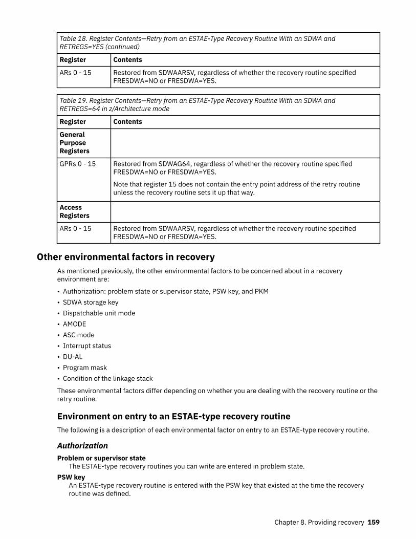
Table 18. Register Contents—Retry from an ESTAE-Type Recovery Routine With an SDWA andRETREGS=YES (continued)
Register Contents
ARs 0 - 15 Restored from SDWAARSV, regardless of whether the recovery routine specifiedFRESDWA=NO or FRESDWA=YES.
Table 19. Register Contents—Retry from an ESTAE-Type Recovery Routine With an SDWA andRETREGS=64 in z/Architecture mode
Register Contents
GeneralPurposeRegisters
GPRs 0 - 15 Restored from SDWAG64, regardless of whether the recovery routine specifiedFRESDWA=NO or FRESDWA=YES.
Note that register 15 does not contain the entry point address of the retry routineunless the recovery routine sets it up that way.
AccessRegisters
ARs 0 - 15 Restored from SDWAARSV, regardless of whether the recovery routine specifiedFRESDWA=NO or FRESDWA=YES.
Other environmental factors in recoveryAs mentioned previously, the other environmental factors to be concerned about in a recoveryenvironment are:
• Authorization: problem state or supervisor state, PSW key, and PKM• SDWA storage key• Dispatchable unit mode• AMODE• ASC mode• Interrupt status• DU-AL• Program mask• Condition of the linkage stack
These environmental factors differ depending on whether you are dealing with the recovery routine or theretry routine.
Environment on entry to an ESTAE-type recovery routineThe following is a description of each environmental factor on entry to an ESTAE-type recovery routine.
AuthorizationProblem or supervisor state
The ESTAE-type recovery routines you can write are entered in problem state.PSW key
An ESTAE-type recovery routine is entered with the PSW key that existed at the time the recoveryroutine was defined.
Chapter 8. Providing recovery 159

PKMAn ESTAE-type recovery routine is entered with the PKM that existed at the time the recovery routinewas defined.
SDWA storage keyAn ESTAE-type recovery routine receives an SDWA in the same storage key as the TCB key at the time therelated task made the first storage request from subpool 0.
Dispatchable unit modeAll ESTAE-type recovery routines receive control in task mode.
AMODEESTAE-type recovery exits receive control in the AMODE that was current at the time-of-set (time-of-PCAMODE for ARRs) with the following exceptions:
• ARR, IEAARR, and ESTAEX exits receive control in AMODE 31 instead of AMODE 24 when establishedfor AMODE 24 programs
ASC modeA recovery routine defined through the ESTAE macro is entered in primary ASC mode. A recovery routinedefined through the ESTAEX macro, the IEAARR macro, or the ESTAI parameter on ATTACHX is entered inthe ASC mode that existed at the time the macro was issued.
Interrupt statusAll ESTAE-type recovery routines are entered enabled for I/O and external interrupts.
DU-ALESTAE-type recovery routines receive control with the DU-AL that was current at the time of the error, asmodified by any previous recovery routines, with the following exception. For an ESTAE-type recoveryroutine activated by an IRB, or activated by an IRB's ESTAE-type recovery routine, the ESTAE-typerecovery routine receives the IRB's DU-AL (IRBs get control with their own DU-AL). The system does notmodify the contents of the DU-AL during recovery processing.
Program maskThe program mask on entry to an ESTAE-type recovery routine is the same as the program mask at thetime of error.
Condition of the linkage stackOn entry to an ESTAE-type recovery routine, the current linkage stack entry is the same as it was at thetime of the error, unless a previous recovery routine added entries to the linkage stack through a PC orBAKR instruction and did not remove them. In such a case, when percolation occurs and the recoveryroutine gets control, the linkage stack contains additional entries beyond what was the current entry atthe time of the error for which the recovery routine received control. IBM recommends that any recoveryroutines that add entries to the linkage stack also remove them.
Restricted environmentsDuring normal task termination, a resource manager might end abnormally; its own recovery routines, ifany exist, will receive control. If they do not retry, or if the resource manager has no recovery routines, thesystem now considers this situation to be an abnormal termination, and passes control to the newestESTAI routine. Because the abending resource manager, and any previous resource managers, might havecompleted some processing, the ESTAI routine will run in an unpredictable environment. In this situation,IBM recommends that you restrict the ESTAI routine's processing. For the ESTAI routine to run in thisenvironment, design it to:
160 z/OS: z/OS MVS Assembler Services Guide

1. Check the STCBRMET field in the STCB; if the bit is on, the ESTAI routine is running after a resourcemanager has ended abnormally and its recovery routines have not retried. In this situation, the ESTAIroutine does not need to hold a lock to check the STCBRMET field. For the mapping of the STCB, seez/OS MVS Data Areas in the z/OS Internet library (www.ibm.com/servers/resourcelink/svc00100.nsf/pages/zosInternetLibrary).
2. Do as little processing as possible, and nothing that might depend on a resource that might have beencleaned up already.
3. Do not request to retry. The system will not allow a retry in this situation.
Note that no other ESTAE-type routines receive control in this situation; only those established throughthe ATTACHX macro still exist at this point in termination processing.
Environment on entry to a retry routine from an ESTAE-type recovery routineThe following is a description of each environmental factor on entry to a retry routine that was specifiedby an ESTAE-type recovery routine.
AuthorizationProblem or supervisor state
The retry routine from an ESTAE-type recovery routine that you can write is entered in problem state.PSW key
If the recovery routine was defined through the ESTAE, ESTAEX, or IEAARR macro, the retry routine isentered with the same PSW key that existed when the macro was issued.
If the recovery routine was defined through the ESTAI parameter of the ATTACHX macro, the retryroutine is entered with the same PSW key as the one in RBOPSW of the retry RB, if the RBOPSW of theretry RB has a key greater than or equal to 8 and is in problem state, and the PKM of that RB does nothave authority to keys less than 8. Otherwise, the PSW key of the retry routine is that of the task inerror.
PKMIf the recovery routine was defined through the ESTAE, ESTAEX, or IEAARR macro, the retry routine isentered with the PKM that existed when the macro was issued.
If the recovery routine was defined through the ESTAI parameter of the ATTACHX macro, the retryroutine is entered with the PKM from the retry RB if the RBOPSW of the retry RB has a key greater thator equal to 8 and is in problem state, and the PKM of that RB does not have authority to keys less than8. Otherwise, the PKM of the retry routine has authority that is equivalent to that of the task in error.
SDWA storage keyIf the recovery routine does not request that the system free the SDWA, the retry routine receives theSDWA in the same storage key as that which the recovery routine received.
Dispatchable unit modeThe retry routine is always entered in task mode.
AMODERetry routines are entered in the same addressing mode that existed when the recovery routine wasentered, unless the SETRP RETRYAMODE= parmeter is used by the recovery routine. See the descriptionof RETRYAMODE= on the SETRP section of the z/OS MVS Programming: Assembler Services Reference IAR-XCT.
ASC modeFor recovery routines defined through the ESTAE macro, the retry routine is entered in primary ASC mode.For recovery routines defined through the ESTAEX macro or through the ESTAI parameter on ATTACHX,the retry routine is entered with the ASC mode of the caller when the macro was issued.
Chapter 8. Providing recovery 161

Interrupt statusThe retry routine is always entered enabled for I/O and external interrupts.
DU-ALThe retry routine is entered with the same DU-AL that the ESTAE-type recovery routine received, asmodified by the ESTAE-type recovery routine. The system does not modify the contents of the DU-ALduring recovery processing.
Program maskWhen the retry routine receives control, the program mask is the one in the RBOPSW for the retry RB,either saved at the time of the last interruption of the RB that occurs while the RB was unlocked andenabled or updated due to an ESPIE routine setting the EPIERSET bit.
Condition of the linkage stackFor recovery routines defined through the ESTAE, ESTAEX or IEAARR macro, on entry to the retry routine,the current linkage stack entry is the same as it was at the time the macro was issued, unless the recoveryroutine has set the SDWALSLV field.
For recovery routines defined through the ESTAI parameter on ATTACHX, on entry to the retry routine, thecurrent linkage stack entry is the same as it was at the time the selected retry RB was entered, unless therecovery routine has set the SDWALSLV field.
Summary of environment on entry to an ESTAE-type recovery routine and itsretry routineTable 20 on page 162 summarizes some of the environmental factors for ESTAE-type recovery routinesunder different conditions. Specifically, the table lists the status information of:
• The caller at the time of issuing the macro• The recovery routine at entry• The retry routine at entry.
Table 20. Environments of ESTAE-type Recovery Routines and their Retry Routines
Type ofRecovery When macro was issued At entry to recovery routine At entry to retry routine
ESTAE ASC mode=primary ASC mode=primary
Linkage stack at time of error (see Note“1” on page 163)
PKM at time macro was issued
ASC mode=primary
Linkage stack at time macro wasissued (see Note “2” on page 163)
PKM at time macro was issued
ESTAEX orIEAARR
ASC mode=primary or AR ASC mode at time macro was issued
Linkage stack at time of error (see Note“1” on page 163)
PKM at time macro was issued
ASC mode at time macro was issued
Linkage stack at time macro wasissued (see Note “2” on page 163)
PKM at time macro was issued
ESTAI(throughATTACHX)
ASC mode=primary or AR ASC mode at time macro was issued
Linkage stack at time of error (see Note“1” on page 163)
PKM at time macro was issued
For possible environment restrictions,see “Restricted environments” on page160.
ASC mode at time macro was issued
Linkage stack at time the retry RB wasentered (see Note “2” on page 163)
Note:
162 z/OS: z/OS MVS Assembler Services Guide

1. The linkage stack presented to the recovery routine might have additional entries, beyond what wasthe current entry at the time of the error, if a previous recovery routine added entries through a PC orBAKR instruction and did not remove them.
2. The linkage stack presented to the retry routine might have additional entries, beyond what wascurrent at the time that the routine was activated, when the recovery routine set the SDWALSLV field.
3. At time of entry to the recovery routine, the AMODE will be the same as the time of invocation, exceptfor ESTAEX and IEAARR routines. ESTAEX and IEAARR routines that were established in AMODE 64receive control in AMODE 64; otherwise, ESTAEX and IEAARR routines always receive control inAMODE 31.
4. The AMODE at the retry point is the same as the AMODE on entry to the recovery routine, unless theSETRP RETRYAMODE= parameter specifies a specific retry AMODE.
5. An ESTAE-type recovery routine is entered with the PSW key that existed at the time it was defined.
Linkage stack at time of retryThere is one retry situation you must avoid: the situation where the retry routine runs with a linkage stackentry that is inappropriate. Consider the following example, where PGM1 activates an ESTAEX routine thathandles recovery for PGM1, PGM2, and PGM3.
caller ---> PGM1 BAKR : ESTAEX : BALR --------> PGM2 BAKR : BALR --------> PGM3 BAKR ***abend*** : retry point : <-------- PR
Both PGM2 and PGM3 use the BAKR instruction to save status; each BAKR adds an entry to the linkagestack. Within PGM3, "retry point" indicates the location where the ESTAEX routine is to retry. After PGM3issues the BAKR instruction, the last entries in the linkage stack are:
• Entry 1 -- caused by PGM1's BAKR• Entry 2 -- caused by PGM2's BAKR• Entry 3 -- caused by PGM3's BAKR
When the abend occurs in PGM3, unless you take special measures, the linkage stack level is reset to thelevel that was current when PGM1 activated the ESTAEX recovery routine. However, retry from the abendin PGM3 occurs within PGM3. The linkage stack level and the retry routine are not "in synch". Measuresyou take to avoid this situation involve:
1. Passing the recovery routine a value that represents the difference between the level of the linkagestack that the retry routine in PGM3 needs and the level of the stack at the time PGM1 activated theESTAEX routine. (In our example, the difference is 2 entries.)
2. Having the recovery routine set the value "2" in the SDWALSLV field in the SDWA.
At a retry, the system uses the value in SDWALSLV to adjust the linkage stack. In this way, the retryroutine has the appropriate current linkage stack entry.
Two ways your program can track the entries in the linkage stack are:
• Count the number of entries added to the stack through BAKRs since PGM1 activated the ESTAEXroutine. Subtract from that total the number of entries taken from the stack through corresponding PRs.
• Issue the IEALSQRY macro, which returns the number as output.
Chapter 8. Providing recovery 163

In either case, the recovery routine must receive the value and must place it in SDWALSLV. In summary,the value in SDWALSLV is the difference between the number of linkage stack entries present when theretry routine gets control and the number that were present when the recovery routine was activated. Thesystem preserves the additional entries on the linkage stack for use by the retry routine. These linkagestack entries must exist at the time of the error; the system does not create any new entries.
The following rules apply to the value in SDWALSLV, as it pertains to linkage stack entries:
• The system ignores the SDWALSLV field when retry is from a STAE or STAI recovery routine.• The value must not reflect entries that were placed on the linkage stack through a PC instruction.• The value must reflect only those entries associated with programs that are problem state and running
with the same PSW key as the program that activated the ESTAE-type recovery routine.• For ESTAE-type routines, the value must reflect only those entries associated with programs that have
been established by a program running under the RB of the retry routine. See “RB considerations” onpage 149.
If any of these rules are broken, retry still occurs but the system ignores the entry that did not conformand all subsequent entries.
Understanding recovery through a coded exampleThis information provides a coded example illustrating a mainline routine with both a recovery routine anda retry routine as entry points in the mainline code.
The code in this example does not contain any real function. The mainline code does little more than savestatus, establish addressability, obtain a dynamic area (making the code reentrant), define a recoveryroutine, and issue the ABEND macro to pass control to the system.
The purpose of the example is just to illustrate how you might code a program that contains both arecovery routine and a retry routine, and how the three routines interact. The example also illustrates howyou design an ESTAE-type recovery routine to allow for the possibility that the system might not providean SDWA.
EXAMPLE CSECT * SAMPLE PROGRAM THAT USES ESTAEXEXAMPLE AMODE 31EXAMPLE RMODE ANY USING EXAMPLE,15 * ESTABLISH TEMPORARY ADDRESSABILITY B @PROLOG * BRANCH AROUND EYE CATCHER DC CL24'EXAMPLE 04/10/92.01' * EYE CATCHER** USE THE LINKAGE STACK TO SAVE STATUS ON ENTRY TO THE PROGRAM.*@PROLOG BAKR 14,0 * SAVE REGISTER/PSW STATUS** ESTABLISH ADDRESSABILITY FOR THIS PROGRAM.* LR 12,15 * REG 12 BECOMES BASE REGISTER DROP 15 * USING EXAMPLE,12 * ESTABLISH ADDRESSABILITY** OBTAIN DYNAMIC STORAGE AREA FOR THIS REENTRANT PROGRAM.* L 2,DYNSIZE * LENGTH TO OBTAIN STORAGE OBTAIN,ADDR=(1),SP=0,LENGTH=(2) LR 13,1 * SAVE DYNAMIC AREA ADDRESS USING DYNAREA,13 * ADDRESSABILITY TO DYNAMIC AREA** SET UP THE REMOTE PARAMETER LIST FOR THE ESTAEX MACRO.* MVC RMTESTAEX(@LSTSIZE),LSTESTAEX** DEFINE AND ACTIVATE AN ESTAEX RECOVERY ROUTINE AT LABEL 'RECOVERY'.* ESTAEX RECOVERY,PARAM=DYNAREA,MF=(E,RMTESTAEX)************************************************************************* CODE FOR THE MAINLINE ROUTINE FUNCTION CAN BE INSERTED HERE** IF AN ERROR OCCURS IN THE MAINLINE ROUTINE, THEN THE SYSTEM WILL* PASS CONTROL TO RECOVERY.
164 z/OS: z/OS MVS Assembler Services Guide

*************************************************************************RETRYPT DS 0H************************************************************************* CODE FOR THE RETRY ROUTINE FUNCTION CAN BE INSERTED HERE************************************************************************ ESTAEX 0 * DELETE THE ESTAEX LR 1,13 * FREE DYNAMIC AREA, ADDRESS TO FREE L 2,DYNSIZE * LENGTH TO FREE STORAGE RELEASE,ADDR=(1),SP=0,LENGTH=(2) PR * RESTORE STATUS & RETURN TO CALLER************************************************************************* RECOVERY ROUTINE************************************************************************RECOVERY DS 0H * ENTRY POINT FOR ESTAEX RECOVERY ROUTINE** HANDLE INPUT FROM THE SYSTEM AND RE-ESTABLISH ADDRESSABILITY FOR* BASE REGISTER (12) AND DYNAMIC AREA REGISTER (13)* PUSH USING DROP , * ENSURE NO SPURIOUS USING REFERENCES USING RECOVERY,15 * TEMPORARY ADDRESSABILITY L 12,#BASE * RELOAD THE BASE REGISTER DROP 15 * RELEASE TEMPORARY ADDRESSABILITY USING EXAMPLE,12 * USE THE BASE REGISTER USING DYNAREA,13 * DYNAMIC AREA ADDRESSABILITY C 0,TESTNOSDWA * IS THERE AN SDWA PRESENT? BE NOSDWA * NO, DO NOT USE THE SDWAHAVESDWA DS 0H USING SDWA,1 * ADDRESSABILITY TO SDWA L 13,SDWAPARM * ADDRESS OF PARAMETER ADDRESS L 13,0(13) * PARAMETER ADDRESS (DYNAREA) MVC SAVE_ABCC,SDWAABCC * SAVE THE COMPLETION CODE B RECOV1 * CONTINUE WITH COMMON RECOVERYNOSDWA LR 13,2 * PARAMETER ADDRESS (DYNAREA) ST 1,SAVE_ABCC * SAVE THE COMPLETION CODE SR 1,1 * NO SDWA IS AVAILABLE, CLEAR REGISTER** COMMON RECOVERY PROCESSING*RECOV1 DS 0H * COMMON RECOVERY PROCESSING ST 1,SAVE_SDWA * SAVE THE SDWA ADDRESS ST 14,SAVE_RETURNR14 * RETURN ADDRESS TO THE SYSTEM************************************************************************** CODE FOR THE RECOVERY ROUTINE FUNCTION SHOULD BE INSERTED HERE************************************************************************** IF THERE IS NO SDWA, THEN SET UP FOR PERCOLATION* L 1,SAVE_SDWA * RESTORE SDWA REGISTER (1) LTR 1,1 * IS THERE AN SDWA? BZ NORETRY * NO, DO NOT ATTEMPT TO RETRY** CHECK SDWACLUP TO SEE IF RETRY IS ALLOWED* TM SDWAERRD,SDWACLUP * IS RETRY ALLOWED? BNZ NORETRY * NO, DO NOT ATTEMPT TO RETRY** SET UP THE RETURN PARAMETERS TO THE SYSTEM. THE SETRP MACRO UPDATES* THE SDWA. NOTE: THE WKAREA PARAMETER DEFAULTS TO REGISTER 1, WHICH* HAS THE ADDRESS OF THE SDWA. ALSO NOTE THAT OTHER REGISTERS MIGHT* NEED TO BE UPDATED TO MEET THE NEEDS OF DIFFERENT PROGRAMS.* ST 12,SDWASR12 * BASE REGISTER 12 FOR RETRY ST 13,SDWASR13 * DYNAMIC AREA REGISTER 13 FOR RETRY SETRP RETREGS=YES,RC=4,RETADDR=RETRYPT,FRESDWA=YES B RECOV2 * CONTINUE WITH COMMON RECOVERYNORETRY DS 0H * BRANCH HERE WHEN NOT GOING TO RETRY LA 15,0 * RETURN CODE TO INDICATE PERCOLATIONRECOV2 DS 0H * COMPLETE THE RETURN TO THE SYSTEM L 14,SAVE_RETURNR14 * SET THE RETURN ADDRESS TO THE SYSTEM BR 14 * RETURN TO THE SYSTEM** STATIC STORAGE AREA
Chapter 8. Providing recovery 165

*TESTNOSDWA DC F'12' * TEST FOR NO SDWA CONDITION#BASE DC A(EXAMPLE) * BASE REGISTER VALUEDYNSIZE DC AL4(@DYNSIZE) * DYNAMIC AREA SIZELSTESTAEX ESTAEX RECOVERY,MF=L * LIST FORM OF ESTAEX PARAMETER LIST@LSTSIZE EQU *-LSTESTAEX * SIZE OF ESTAEX PARAMETER LIST** DYNAMIC AREA STORAGE FOR REENTRANT PROGRAM*DYNAREA DSECT * DYNAMIC STORAGESAVEAREA DS 18F * REGISTER SAVE AREASAVE_SDWA DS F * SDWA ADDRESS ON ENTRY TO RECOVERYSAVE_ABCC DS F * COMPLETION CODESAVE_RETURNR14 DS F * RETURN ADDR. TO SYSTEM FROM RECOVERYRMTESTAEX DS CL(@LSTSIZE) * REMOTE ESTAEX PARAMETER LISTSTATUS DS F * MAINLINE STATUS INDICATOR@ENDDYN DS 0X * USED TO CALCULATE DYNAMIC AREA SIZE@DYNSIZE EQU ((@ENDDYN-DYNAREA+7)/8)*8 * DYNAMIC AREA SIZE** INCLUDE MACROS* IHASDWA END
Understanding advanced recovery topicsThis information contains information about the following advanced recovery topics:
• “Invoking RTM (ABEND macro)” on page 166• “Providing multiple recovery routines” on page 167• “Providing recovery for recovery routines” on page 167• “Providing recovery for multitasking programs” on page 168.
Invoking RTM (ABEND macro)Any routine can issue the ABEND macro to direct the recovery termination services to itself (cause entryinto its recovery routine) or to its callers. The issuer of ABEND should remove its own recovery routine if itwishes its caller to be ended abnormally or to enter recovery. Control does not return to the issuer of themacro (except as a result of a retry).
The position within the job step hierarchy of the task for which the ABEND macro is issued determines theexact function of the abnormal termination routine. If an ABEND macro is issued when the job step task(the highest level or only task) is active, or if the STEP parameter is coded in an ABEND macro issuedduring the performance of any task in the job step, all the tasks in the job step are terminated. Forexample, if the STEP parameter is coded in an ABEND macro under TSO/E, the TSO/E job is terminated.An ABEND macro (without a STEP parameter) that is issued in performance of any task in the job step taskusually causes only that task and its subtasks to be abnormally terminated. However, if the abnormaltermination cannot be fulfilled as requested, it might be necessary for the system to end the job step taskabnormally.
If you have provided a recovery routine for your program, the system passes control to your routine. If youhave not provided a recovery routine, the system handles the problem. The action the system takesdepends on whether the job step is going to be terminated.
If the job step is not going to be terminated, the system:
• Releases the resources owned by the terminating task and all of its subtasks, starting with the lowestlevel task.
• Places the system or user completion code specified in the ABEND macro in the task control block (TCB)of the active task (the task for which the ABEND macro was issued).
• Posts the event control block (ECB) with the completion code specified in the ABEND macro, if the ECBparameter was coded in the ATTACHX macro issued to create the active task.
• Schedules the end-of-task exit routine to be given control when the originating task becomes active, ifthe ETXR parameter was coded in the ATTACHX macro issued to create the active task.
166 z/OS: z/OS MVS Assembler Services Guide

• Calls a routine to free the storage of the terminating task's TCB, if neither the ECB nor ETXR parameterwere specified by the ATTACHX macro.
If the job step is to be terminated, the system:
• Releases the resources owned by each task, starting with the lowest level task, for all tasks in the jobstep. The system does not give control to any end-of-task exit.
• Writes the system or user completion code specified in the ABEND macro on the system output device.
The remaining steps in the job are skipped unless you can define your own recovery routine to performsimilar functions and any other functions that your program requires. Use either the ESTAE or ESTAEXmacro, or the ATTACHX macro with the ESTAI option to provide a recovery routine that gets controlwhenever your program issues an ABEND macro. If your program is running in AR ASC mode, use theESTAEX or ATTACHX macro.
Providing multiple recovery routinesA single program can activate more than one ESTAE-type recovery routine by issuing the ESTAE or ESTAEXmacro more than once with the CT parameter. The program can also overlay recovery routines by issuingESTAE or ESTAEX with the OV parameter, or deactivate recovery routines by issuing ESTAE or ESTAEX withan address of zero.
ESTAE-type recovery routines get control in LIFO order, so the last ESTAE-type recovery routine activatedis the first to get control. Remember that ESTAE-type recovery routines include ESTAE and ESTAEXroutines, and ESTAI routines. ESTAI routines are entered after all other ESTAE-type recovery routines thatexist for a given task have received control and have either failed or percolated.
MVS functions provide their own recovery routines; thus, percolation can pass control to both installation-written and system-provided recovery routines. If all recovery routines percolate -- that is, no recoveryroutine can recover from the error -- then the task is terminated.
When a recovery routine gets control and cannot recover from the error (that is, it does not retry), it mustfree the resources held by the mainline routine and request that the system continue with errorprocessing (percolate). Note that a recovery routine entered with the SDWACLUP bit set to one, indicatingthat retry is not permitted, has no choice but to percolate. When the recovery routine requestspercolation, the previously activated recovery routine gets control. When a retry is not requested and thesystem has entered all possible recovery routines, the task ends abnormally.
When a recovery routine requests percolation, it is deactivated; that is, it can no longer get control for thiserror. A deactivated recovery routine is not entered again unless that recovery routine is activated againafter a retry.
Providing recovery for recovery routinesIn some situations, the function a recovery routine performs is so essential that you should provide arecovery routine to recover from errors in the recovery routine. Two examples of such situations are:
1. The availability of some resources can be so critical to continued system or subsystem operation that itmight be necessary to provide a recovery routine for the recovery routine, thus ensuring the availabilityof the critical resources.
2. A recovery routine might perform a function that is, in effect, an extension of the mainline routine'sprocessing. For example, a system service might elect to check a caller's parameter list for fetch orstore protection. The service references the user's data in the user's key and, as a result of protection,suffers a program check. The recovery routine gets control and requests a retry to pass a particularreturn code to the mainline routine. If this recovery routine ends abnormally and does not provide itsown recovery, then the caller's recovery routine gets control, and the caller does not get anopportunity to check the return code that it was expecting.
You can activate an ESTAE-type recovery routine from another ESTAE-type recovery routine. Any recoveryroutine activated from a recovery routine is called a nested recovery routine. Nested ESTAE or ESTAEXroutines can retry; the retry routine runs under the RB of the ESTAE-type recovery routine that activatedthe nested recovery routine.
Chapter 8. Providing recovery 167

Providing recovery for multitasking programsThere are situations where the system does not provide serialization between recovery routines fordifferent TCBs in an address space. When possible you should write your recovery routines so thatserialization is not required.
When a recovery routine requires serialization with other TCBs in the address space then the recoveryroutine must provide its own serialization. Serialization must be carefully designed to avoid causingdeadlock situations.
One serialization technique to ensure the order of termination processing is to use the DETACH macro.Issuing DETACH ensures that the detached task and its recovery routines complete before processing forthe issuing task proceeds. DETACH can only be used for tasks that were directly attached by the recoveryroutine's TCB.
Another important aspect of recovery is releasing resources. Releasing serialization resources (locks,ENQs, latches) in ESTAE-type recovery routines, rather than leaving them to be released by a resourcemanager, helps avoid deadlocks in recovery processing.
Using STAE/STAI routinesNote to reader
• IBM recommends that you use the ESTAEX or ESTAE macro, or the ESTAI parameter on ATTACHX.• Under certain circumstances, STAE or STAI routines might receive control in a restricted environment.
See “Restricted environments” on page 160 for more information.
End of Note to reader
The STAE macro causes a recovery routine address to be made known to the system. This recoveryroutine is associated with the task and the RB that issued STAE. Use of the STAI option on the ATTACHmacro also causes a recovery routine to be made known to the system, but the routine is associated withthe subtask created through ATTACH. Furthermore, STAI recovery routines are propagated to all lower-level subtasks of the subtask created with ATTACH that specified the STAI parameter.
If a task is scheduled for abnormal termination, the recovery routine specified by the most recently issuedSTAE macro gets control and runs under a program request block created by the SYNCH service routine.Only one STAE routine receives control. The STAE routine must specify, by a return code in register 15,whether a retry routine is to be scheduled. If no retry routine is to be scheduled (return code = 0) and thisis a subtask with STAI recovery routines, the STAI recovery routine is given control. If there is no STAIrecovery routine, abnormal termination continues.
If there is more than one STAI recovery routine existing for a task, the newest one receives control first. Ifit requests that termination continue (return code = 0), the next STAI routine receives control. Thiscontinues until either all STAI routines have received control and requested that the termination continue,a STAI routine requests retry (return code = 4 or 12), or a STAI routine requests that the terminationcontinue but no further STAI routines receive control (return code = 16).
Programs running under a single TCB can issue more than one STAE macro with the CT parameter todefine more than one STAE routine. Each issuance temporarily deactivates the previous STAE routine. Theprevious STAE routine becomes active when the current STAE routine is deactivated.
A STAE routine is deactivated (it cannot receive control again for this error) under any of the followingcircumstances:
• When the RB that activated it goes away (unless it issued XCTL and specified the XCTL=YES parameteron the STAE macro)
• When the STAE macro is issued with an address of 0• When the STAE routine receives control.
If a STAE routine receives control and requests retry, the retry routine reissues the STAE macro if it wantscontinued STAE protection.
168 z/OS: z/OS MVS Assembler Services Guide

A STAI routine is deactivated if the task completes or if the STAI routine requests that terminationcontinue and no further STAI processing be done. In the latter case, all STAI recovery routines for the taskare deactivated.
STAE and STAI routine environment:
Prior to entering a STAE or STAI recovery routine, the system attempts to obtain and initialize a work areathat contains information about the error. The first 4 bytes of the SDWA contains the address of the userparameter area specified on the STAE macro or the STAI parameter on the ATTACH macro.
Upon entry to the STAE or STAI routine, the GPRs contain the following:
If an SDWA was obtained:GPR
Contents0
A code indicating the type of I/O processing performed:
0Active I/O has been quiesced and is restorable.
4Active I/O has been halted and is not restorable.
8No active I/O at abend time.
16 (X'10')Active I/O, if any, was allowed to continue.
1Address of the SDWA.
2Address of the parameter area you specified on the PARAM parameter.
3 - 12Do not contain any information for use by the routine.
13Save area address.
14Return address.
15Address of STAE recovery routine.
If no SDWA was available:GPR
Contents0
12 (X'0C') to indicate that no SDWA was obtained.1
Completion code.2
Address of user-supplied parameter list.3 - 13
Do not contain any information for use by the routine.14
Return address.
Chapter 8. Providing recovery 169

15Address of STAE recovery routine.
When the STAE or STAI routine has completed, it should return to the system through the contents of GPR14. GPR 15 should contain one of the following return codes: Return Code
Action0
Continue the termination. The next STAI, ESTAI, or ESTAE routine will be given control. No other STAEroutines will receive control.
4,8,12A retry routine is to be scheduled.
Note: These values are not valid for STAI/ESTAI routines that receive control when a resourcemanager fails during normal termination of a task. See “Restricted environments” on page 160 formore information.
16No further STAI/ESTAI processing is to occur. This code may be issued only by a STAI/ESTAI routine
For the following situations, STAE/STAI routines are not entered:
• If the abnormal termination is caused by an operator's CANCEL command, job step timer expiration, orthe detaching of an incomplete task without the STAE=YES option.
• If the failing task has been in a wait state for more than 30 minutes.• If the STAE macro was issued by a subtask and the attaching task abnormally terminates.• If the recovery routine was specified for a subtask, through the STAI parameter of the ATTACH macro,
and the attaching task abnormally terminates.• If a problem other than those already described arises while the system is preparing to give control to
the STAE routine.• If another task in the job step terminates without the step option.
STAE and STAI retry routines:
If the STAE retry routine is scheduled, the system automatically deactivates the active STAE routine; thepreceding STAE routine, if one exists, then becomes activated. Users wanting to maintain STAE protectionduring retry must reactivate a STAE routine within the retry routine, or must issue multiple STAE requestsprior to the time that the retry routine gains control.
Like the STAE/STAI recovery routine, the STAE/STAI retry routine must be in storage when the recoveryroutine determines that retry is to be attempted. If not already resident in your program, the retry routinemay be brought into storage through the LOAD macro by either the mainline routine or the recoveryroutine.
If the STAE/STAI routine indicates that a retry routine has been provided (return code = 4, 8, or 12),register 0 must contain the address of the retry routine. The STAE routine that requested retry isdeactivated and the request block queue is purged up to, but not including, the RB of the program thatissued the STAE macro. In addition, open DCBs that can be associated with the purged RBs are closed andqueued I/O requests associated with the DCBs being closed are purged.
The RB purge is an attempt to cancel the effects of partially run programs that are at a lower level in theprogram hierarchy than the program under which the retry occurs. However, certain effects on the systemare not canceled by this RB purge. Generally, these effects are TCB-related and are not identifiable at theRB level. Examples of these effects are as follows:
• Subtasks created by a program to be purged. Subtasks cannot be associated with an RB; the structure isdefined through TCBs.
• Resources allocated by the ENQ macro. ENQ resources are associated with the TCB and are notidentifiable at the RB level.
170 z/OS: z/OS MVS Assembler Services Guide

• DCBs that exist in dynamically acquired virtual storage. Only DCBs in the program, as defined by the RBthrough the CDE itself, are closed.
If there are quiesced restorable input/output operations (as specified by PURGE=QUIESCE on the macroinvocation), the retry routine can restore them in the same manner as the retry routine from an ESTAEroutine. See “Outstanding I/Os at the time of failure” on page 150.
If an SDWA was obtained upon entry to the STAE/STAI retry routine, the contents of the GPRs are asfollows: GPR
Contents0
01
Address of the first 104 bytes of the SDWA.2 - 14
Do not contain any information for use by the routine.15
Address of the STAE/STAI retry routine.
When the storage is no longer needed, the retry routine should use the FREEMAIN macro with the defaultsubpool to free the first 104 bytes of the SDWA.
If the system was not able to obtain storage for the work area, GPR contents are as follows:GPR
Contents0
12 (X'0C')1
Completion code.2
Address of purged I/O restore list or 0 if I/O is not restorable.3 - 14
Do not contain any information for use by the routine.15
Address of the STAE/STAI retry routine.
The retry routine is entered with the same PSW key as the one in the RBOPSW of the retry RB if theRBOPSW of the retry RB has a key greater than or equal to 8 and is in problem program state, and thePKM of that RB does not have authority to keys less than 8.
Otherwise, the PSW key of the retry routine is that of the task in error.
Chapter 8. Providing recovery 171

172 z/OS: z/OS MVS Assembler Services Guide

Chapter 9. Dumping virtual storage (ABEND, SNAPX,SNAP, and IEATDUMP macros)
A problem-state and PSW key 8-15 program can request three types of storage dumps:
• An ABEND dump obtained through the DUMP parameter in the ABEND macro, or the DUMP=YESparameter on the SETRP macro in a recovery exit
• A SNAP dump obtained through the SNAPX macro.• A Transaction dump obtained througfh the IEATDUMP macro.
Table 21 on page 173 summarizes reasons for selecting an ABEND, SNAP, or Transaction dump.
Table 21. Reasons for Selecting the Type of Dump
Type of Dump Reasons for Selecting the Type of Dump
ABEND dumps Use an ABEND dump when abnormally ending a program because of an unpredictableerror. The DD statement in the program's job step determines the type of ABEND dumpand the dump contents, as follows:
• SYSUDUMP ABEND dumps
These are the smallest of the ABEND dumps, containing data and areas only about thefailing program. You can either print or view the dump if it's in a SYSOUT data set or ona tape or direct access data set (DASD).
• SYSABEND ABEND dumps
These are the largest of the ABEND dumps, containing all the areas in a SYSUDUMPdump and system areas that are used to analyze the processing in the failing program.You can either print or view the dump if it's in a SYSOUT data set or on a tape or DASD.
• SYSMDUMP ABEND dumps
These contain data and areas in the failing program, plus some system areas. TheSYSMDUMP dumps can be more useful for diagnosis than other ABEND dumpsbecause you can use IPCS to gather diagnostic information. Use IPCS to format, view,and print dumps.
SNAP dumps Use a SNAP dump to show one or more user-specified areas in the problem-stateprogram while it is running. A series of SNAP dumps can show a storage area at differentstages to display a program's processing. For example, you can use SNAP dumps toshow fields holding calculations and the counter in a loop to check processing in theloop.
Transaction dumps(IEATDUMP)
Use Transaction dumps to request unformatted dumps of virtual storage, similar to whatSDUMPX offers for authorized programs. IPCS is used to analyze, view and print thedump information. This enables more program analysis possibilities than a formattedSNAP dump. Plus, by adding symptoms using the SYMREC parameter, duplicate dumpscan be suppressed by DAE.
z/OS MVS Diagnosis: Tools and Service Aids shows, in detail, the contents of dumps. z/OS MVS IPCS User'sGuide describes how to use IPCS. z/OS MVS Programming: Authorized Assembler Services Guide describesmacros that authorized programs can use to dump virtual storage.
© Copyright IBM Corp. 1988, 2020 173

ABEND dumpsAn ABEND macro initiates error processing for a task. The DUMP option of ABEND requests a dump ofstorage and the DUMPOPT or DUMPOPX option may be used to specify the areas to be displayed. Thesedump options may be expanded by an ESTAE or ESTAI routine. The system usually requests a dump foryou when it issues an ABEND macro. However, the system can provide an ABEND dump only if you includea DD statement (SYSABEND, SYSMDUMP, or SYSUDUMP) in the job step. The DD statement determinesthe type of dump provided and the system dump options that are used. When the dump is taken, thedump options that you requested (specified in the ABEND macro or by recovery routines) are added to theinstallation-selected options.
When writing an ESTAE-type recovery routine, note that the system accumulates the SYSABEND/SYSUDUMP/SYSMDUMP dump options specified by means of the SETRP macro and places them in theSDWA. During percolation, these options are merged with any dump options specified on an ABEND orCALLRTM macro or by other recovery routines. Also, the CHNGDUMP operator command can add to oroverride the options. The system takes one dump as specified by the accumulated options. If the recoveryroutine requests a retry, the system processes the dump before the retry. If the recovery routine does notrequest a retry, the system percolates through all recovery routines before processing the dump.
Note: If your program calls a system service (by issuing a macro or callable service), that system servicemight encounter a user-induced error and end abnormally. Generally, the system does not take dumps foruser-induced errors. If you require such a dump, then it is your responsibility to request one in yourrecovery routine. See Chapter 8, “Providing recovery,” on page 127 for information about writing recoveryroutines.
Obtaining a symptom dumpWith all ABEND dumps, you will automatically receive a symptom dump through message IEA995I. Thissymptom dump provides a summary of error information, which will help you to identify duplicateproblems.
You will receive this dump even without a DD statement unless your installation changes the default viathe CHNGDUMP operator command or the dump parmlib member for SYSUDUMP.
Suppressing dumps that duplicate previous dumpsIf your installation is using dump analysis and elimination (DAE), code your program to provide symptomdata that DAE can compare with the symptom data from previous dumps. Through this comparison, DAEcan reduce the number of duplicate dumps. Another benefit is that the symptom data, which is stored inthe DAE data set, provides a consistent set of data for identifying a failure.
DAE suppresses dumps that match a dump you already have. Each time DAE suppresses a duplicatedump, the system does not collect data for the duplicate or write the duplicate to a data set. In this way,DAE can improve dump management by only dumping unique situations and by minimizing the number ofdumps.
To perform dump suppression, DAE builds a symptom string, if the data for it is available. If the symptomstring contains the minimum problem data, DAE uses the symptom string to recognize a duplicate SVCdump, SYSMDUMP dump, or Transaction dump requested for a software error. When installationparameters request suppression, DAE suppresses the duplicate dump. The following describes DAEprocessing.
1. DAE obtains problem data. DAE receives the data in the system diagnostic work area (SDWA) or fromvalues in a SYMREC parameter on the SDUMP, SDUMPX or IEATDUMP macro that requested the dump.
• The system supplies system-level data, such as the abend and reason codes, the failing instruction,and the register/PSW difference.
• The ESTAE routine or the functional recovery routine (FRR) of the failing program supplies module-level information, such as the failing load module name and the failing CSECT name.
174 z/OS: z/OS MVS Assembler Services Guide

2. DAE forms a symptom string. DAE adds a descriptive keyword to each field of problem data to form asymptom. DAE forms MVS symptoms, rather than RETAIN symptoms. DAE combines the symptoms fora requested dump into a symptom string.
The following tables show the required and optional symptoms. SDWA field names are given for thesymptoms the failing program must provide to enable dump suppression. The tables have both MVSand RETAIN symptoms so that you can relate the MVS symptoms DAE uses to the RETAIN symptomsyou might use to search the RETAIN data base. An MVS symptom string must contain at least fivesymptoms that are not null. DAE places symptoms into strings in the order shown in the tables.
Required symptoms are first and must be present.
Symptom SDWA Field MVS Keyword RETAINKeyword
Name of the failing load module SDWAMODN MOD/name RIDS/name#L
Name of the failing CSECT SDWACSCT CSECT/name RIDS/name
Optional symptoms must follow the required symptoms. DAE needs at least three of these optionalsymptoms to make a useful symptom string.
Symptom SDWA Field MVS Keyword RETAINKeyword
Product/component identifier with the componentidentifier base
SDWACID,SDWACIDB
PIDS/name PIDS/name
System completion (abend) code AB/S0hhh AB/S0hhh
User completion (abend) code AB/Udddd AB/Udddd
Recovery routine name SDWAREXN REXN/name RIDS/name#R
Failing instruction area FI/area VALU/Harea
PSW/register difference REGS/hhhhh REGS/hhhhh
Reason code, accompanying the abend code or fromthe REASON parameter of the macro that requests thedump
HRC1/nnnn PRCS/nnnn
Subcomponent or module subfunction SDWASC SUB1/name VALU/Cname
3. DAE tries to match the symptom string from the dump to a symptom string for a previous dump ofthe same type, that is, SVC dumps, with SVC dumps and SYSMDUMP, or Transaction dumps with aprevious SYSMDUMP or Transaction dump. When DAE finds a match, DAE considers the dump to be aduplicate.
When DAE is started, usually during IPL, DAE selects from the symptom strings (stored in the DAE dataset) that were active in the last 60 days: either the string was created for a unique dump within the last60 days, or its dump count was updated within the last 60 days. The selected symptom strings areplaced in virtual storage.
The systems in a sysplex can share the DAE data set to suppress duplicate dumps across the sysplex.While each system in a sysplex can use its own DAE data set, IBM recommends that systems in asysplex share a DAE data set so that:
• DAE can write a dump on one system and suppress duplicates on other systems in the sysplex.• Only one DAE data set is required, rather than a data set for each system.
4. DAE updates the symptom strings in storage and, later, in the DAE data set, if updating isrequested.
Chapter 9. Dumping virtual storage (ABEND, SNAPX, SNAP, and IEATDUMP macros) 175

• For a unique symptom string, DAE adds a new record. The record contains the symptom string, thedates of the first and last occurrences, the incidence count for the number of occurrences, and thename of the system that provided the string.
• For a duplicate symptom string, DAE updates the incidence count for the string, the last-occurrencedate, and the name of the last system that found the string.
In a sysplex, changes to the in-storage strings are propagated to the in-storage strings throughout thesysplex.
5. DAE suppresses a duplicate dump, if DAE is enabled for dump suppression.
Note that, if you specify an ACTION of SVCD, TRDUMP, NOSUP, or RECOVERY on a SLIP command, thecommand overrides DAE suppression and the system writes the dump. Also, dumps requested by theDUMP operator command are not eligible for suppression.
When DAE does not suppress a dump, the symptom string is in the dump header; you can view it withthe IPCS VERBEXIT DAEDATA subcommand. DAE also issues informational messages to indicate whythe dump was not suppressed.
DAE suppresses a dump when all of the following are true:
• DAE located in the dump the minimum set of symptoms.• The symptom string for the dump matches a symptom string for a previous dump of the same type.• Either of the following is true:
– The current ADYSETxx parmlib member specifies SUPPRESS for the type of dump being requestedand the VRADAE key is present in the SDWA. To set the VRADAE key, a recovery routine issues thefollowing macro:
VRADATA KEY=VRADAE
– A VRADATA VRAINIT must be done prior to any VRADATA KEY= request in order for the VRA datato be properly processed by both DAE and the SDWA formatter.
– The current ADYSETxx parmlib member specifies SUPPRESSALL for the type of dump beingrequested and the VRANODAE key is absent from the SDWA. The VRANODAE key specifies thatthe dump is not to be suppressed.
The following table shows the effect of the VRADAE and VRANODAE keys on dump suppression whenSUPPRESS and SUPPRESSALL keywords are specified in the ADYSETxx parmlib member. ForSUPPRESS, the VRANODAE key can be present or absent; the system does not check it. The tableassumes that the symptom string from the dump has matched a previous symptom string.
ADYSETxx Option VRADAE Key in SDWA VRANODAE Key inSDWA
Dump Suppressed?
SUPPRESS Yes N/A Yes
SUPPRESS No N/A No
SUPPRESSALL Yes No Yes
SUPPRESSALL No Yes No
SUPPRESSALL No No Yes
SUPPRESSALL Yes Yes No
The only way to ensure that a dump is not suppressed, regardless of the contents of the ADYSETxxparmlib member, is to specify the VRANODAE key in the SDWA, or DAE=NO on SYMRBLD used to builda symptom record passed to the SDUMPX or IEATDUMP macro with the SYMREC keyword.
References:
• See z/OS MVS Diagnosis: Reference for symptoms and symptom strings.
176 z/OS: z/OS MVS Assembler Services Guide

• See z/OS MVS Initialization and Tuning Reference for the ADYSETxx and IEACMD00 parmlib members.• See z/OS MVS IPCS Commands for the VERBEXIT DAEDATA subcommand.
Symptoms provided by a recovery routineDAE attempts to construct a unique symptom string using specific data that your recovery routine canprovide in the SDWA or through a symptom record. For an SVC dump, or a Transaction dump, thesymptom record is passed in the SDUMPX or IEATDUMP macro. For a SYSMDUMP, place the symptomrecord in the ABDUMP symptom area.
To provide symptoms for an SVC dump, do one or more of the following in a recovery routine:
• Place data in the SDWA, which is mapped by the IHASDWA mapping macro.• In an authorized program, provide a symptom record through a SYMREC parameter on the SDUMPX or
SDUMP macro. The symptom record is built using SYMRBLD and mapped by the ADSR mapping macro.• In an authorized or unauthorized program, provide a symptom record through a SYMREC parameter on
the IEATDUMP macro. The symptom record is built using SYMRBLD and mapped by the ADSR mappingmacro.
• Use a VRADATA macro to place information in the SDWA variable recording area (VRA), which is mappedby the IHAVRA mapping macro. The VRA is used:
– To supply additional symptoms for the symptom string.– To provide secondary symptoms that give problem data not given in the SDWA; for example, the
identity of the caller of a service.
Use VRADATA when the standard symptom data is insufficient to determine if a dump for the program isa duplicate.
For information about coding the VRADATA macro to add data to the SDWA, see z/OS MVS Programming:Assembler Services Reference IAR-XCT. For more information about symptom records, see Chapter 10,“Reporting symptom records (SYMRBLD and SYMREC macros),” on page 181. For more information aboutrecovery routines, see “Writing recovery routines” on page 135.
VRADATA macro: Use the VRAREQ key to tell DAE that the symptom is required and the VRAOPT key totell DAE that the symptom is optional.
A VRADATA macro with VRAREQ adds a symptom following the two required symptoms (see the previoustable). For example, to add a symptom, in this case the name of a data set, and to define the symptom asrequired:
VRADATA KEY=VRAREQ,DATA=TAG1,LEN=L'TAG1VRADATA KEY=VRADSN,DATA=MYDSN,LEN=L'MYDSN⋮TAG1 DC AL2(VRADSN)MYDSN DC C'DEPT27.PAYROLL'
A VRADATA macro with VRAOPT adds an optional symptom following the optional symptoms (see theprevious table). For example, to add an optional symptom with the data at the address in register 5, and todefine the symptom as optional:
LA R5,VRAOPTKEYVRADATA KEY=VRAOPT,LEN=2,DATA=(5)VRADAYA KEY=VRACA,DATA=PGMCALLR⋮VRAOPTKEY DC AL2(VRACA)PGMCALLR DS A
If the symptom is to be the caller's address, the data pointed to would consist of X'003C', whichrepresents the key VRACA.
See z/OS MVS Diagnosis: Reference for the VRADATA keys.
Required symptom data: The recovery routine must provide the following minimum data to enable dumpsuppression by DAE:
Chapter 9. Dumping virtual storage (ABEND, SNAPX, SNAP, and IEATDUMP macros) 177

SDWA Field Data Example
SDWAMODN Failing module name IEAVTCXX
SDWACSCT Failing CSECT name IEAVTC22
SDWACID Product or component identifier SCDMP
SDWACIB Component identifier base 5655
SDWAREXN Recovery routine name IEAVTC2R
SDWASC Subcomponent or module subfunction RSM-PGFIX
To obtain the failing module name, the failing CSECT name, and the recovery module name, the recoveryroutine can set up a RECPARM parameter list and specify it on a SETRP macro. For information, see theRECPARM parameter of the SETRP macro in z/OS MVS Programming: Authorized Assembler ServicesReference SET-WTO.
Correct module and CSECT names: Obtaining the correct module and CSECT names may be difficult,especially when the PSW does not point within the program areas. Problems can also occur when theprogram uses the following:
• User exits: When the program calls a user exit, which in turn invokes system services, such as getting alock, the recovery routine often cannot identify the exit as the failing module and CSECT. To avoid thisproblem, the program should save the name of the user exit, so that the recovery routine can use thesaved name.
• Common recovery routines: The program should maintain footprints or require that all modules using acommon recovery routine update a common parameter list with the name of the current module,CSECT, subfunction, and so on. The recovery routine can obtain data from the common parameter listwhen filling in the SDWA.
Symptoms: When you provide symptom information, select each symptom carefully. If a symptom is tooprecise, no other failure will have that symptom; if the symptom is too general, many failures will have thesame symptom. For example, do not use addresses as symptoms; instead, use names of modules andcomponents.
DAE accumulates up to 20 specified required and optional symptoms and up to 20 additional symptoms,if specified. The maximum string length is 150, so that not all of the additional symptoms may appear inthe string. A recovery routine can change the minimum number of symptoms and the minimum stringlengths that DAE is to use for symptom matching for a particular dump. To make these changes, code thefollowing VRADATA macro keys in the recovery routine:
• The VRAMINSC key controls the minimum number of symptoms.• The VRAMINSL key controls the minimum string length.
Control of suppression: When the ADYSETxx parmlib member being used by the installation containsSUPPRESS, a recovery routine must indicate that enough data is available to suppress a duplicate dump.To indicate to DAE that the SDWA contains enough data, set the VRADAE indicator in the SDWA variablerecording area by issuing the following:
VRADATA KEY=VRADAE
If the recovery routine cannot provide enough data in the SDWA suppression, the recovery routine shouldindicate that its dump is not eligible for suppression, even when the ADYSETxx member containsSUPPRESSALL. The routine should set the VRANODAE indicator by issuing the following:
VRADATA KEY=VRANODAE
The VRANODAE key is useful for error environments that generate identical symptoms but representdifferent problems.
178 z/OS: z/OS MVS Assembler Services Guide

When a dump is not suppressedWhen DAE is active but does not suppress a dump, DAE adds the reason that the dump is not suppressedto the dump header record. When viewing a dump online or printing a dump, specify the IPCS VERBEXITDAEDATA subcommand to see the reason that a dump was not suppressed.
Some reasons for not suppressing a dump are:
• The dump is unique. DAE found no match for the symptom string.• The current ADYSETxx member does not specify SUPPRESS or SUPPRESSALL for the type of dump
being requested.• A SLIP operator command specifies that the dump is not to be suppressed. A SLIP command with
ACTION=SVCD, ACTION=SYNCSVCD, ACTION=STDUMP, ACTION=RECOVERY, or ACTION=TRDUMPalways produces a dump. ACTION=NOSUP stops suppression.
• DAE could not find all required symptoms.• DAE could not find the minimum number of symptoms.• The symptom string built by DAE was shorter than the minimum length.• DAE found certain errors. For example, a required symptom had a key that was not valid.• The VRADAE key in the SDWA is absent, signifying that the dump should not be suppressed, and the
DAE parameter of the ADYSETxx parmlib member does not specify SUPPRESSALL.• The VRANODAE key is present in the SDWA, specifying that the dump should not be suppressed.
SNAP dumpsA program can request a SNAP dump at any time during its processing by issuing a SNAPX or SNAP macro.For a SNAP dump, the DD statement can have any name except SYSABEND, SYSMDUMP, and SYSUDUMP.
If your program is in AR ASC mode, use the SNAPX macro instead of SNAP. Ensure that the SYSSTATEASCENV=AR macro has been issued to tell the macro to generate code and addresses appropriate forcallers in AR mode.
Like the ABEND dump, the data set containing the dump can reside on any device that is supported byBSAM. The dump is placed in the data set described by the DD statement you provide. If you select aprinter, the dump is printed immediately. However, if you select a direct access or tape device, you mustschedule a separate job to obtain a listing of the dump, and to release the space on the device.
To obtain a dump using the SNAP macro, you must provide a data control block (DCB) and issue an OPENmacro for the data set before issuing any SNAP macros. If the standard dump format is requested, 120characters per line are printed. The DCB must contain the following parameters: DSORG=PS,RECFM=VBA, MACRF=W, BLKSIZE=882 or 1632, and LRECL=125. (The DCB is described in z/OS DFSMSUsing Data Sets, and z/OS DFSMS Macro Instructions for Data Sets). If a high-density dump is to be printedon a 3800 Printing Subsystem, 204 characters per line are printed. To obtain a high-density dump, codeCHARS=DUMP on the DD statement describing the dump data set. The BLKSIZE= must be either 1470 or2724, and the LRECL= must be 209. CHARS=DUMP can also be coded on the DD statement describing adump data set that will not be printed immediately. If CHARS=DUMP is specified and the output device isnot a 3800, print lines are truncated and print data is lost. If your program is to be processed by theloader, you should also issue a CLOSE macro for the SNAP DCB.
Finding information in a SNAP dumpYou will obtain a dump index with each SNAP dump. The index will help you find information in the dumpmore quickly. Included in the information in the dump index is an alphabetical list of the active loadmodules in the dump along with the page number in the dump where each starts.
Obtaining a summary dump for an ABEND or SNAP dumpYou can request a summary dump for an abending task by coding the SUM option of the SNAP macro. Youcan also obtain a summary dump by coding the DUMPOPT option on the ABEND or SETRP macro and
Chapter 9. Dumping virtual storage (ABEND, SNAPX, SNAP, and IEATDUMP macros) 179

specifying a list form of SNAP that contains the SUM option. Use the DUMPOPX parameter on ABEND orSETRP to obtain an ABEND dump that contains data space storage. When you use DUMPOPX, specify alist form of SNAPX that contains the SUM option.
If SUM is the only option that you specify, the dump will contain a dump header, control blocks, andcertain other areas. The contents of the summary dump are described in z/OS Problem Management.
Transaction dumpsTransaction dump is a service used to request an unformatted dump of virtual storage to a data set,similar to a SYSMDUMP. It is invoked with the IEATDUMP assembler macro which issues SVC 51. You caneither request that the dump be written to a preallocated data set or to automatically allocated data sets.To request a preallocated data set, specify the DDNAME parameter that identifies a data set that containssufficient space in one or more extents for the entire dump to be written. If you don't provide a largeenough data set, you will receive a partial dump. To request automatic allocation, specify the DSN andDSNAD parameters, which ensure a dump will not be truncated due to data set space constraints.Automatic allocation is done to SYSALLDA. When using DSN or DSNAD, the maximum size is 2 GB, unlessthe dump is split among several data sets, in which case there is no restriction. DDNAME also does nothave the 2 GB size restriction.
When a Transaction dump is written, a dump directory record describing the dump may be written.Specify the dump directory to be used with the IDX keyword on the dump request. If you do not specify adump directory, the directory allocated to IPCSDDIR in the current job step will be used. If no dumpdirectory is specified and IPCSDDIR is not allocated, no record describing the dump will be written.
Dump suppression occurs using symptoms available in the current SDWA or a symptom string may beprovided (via the SYMREC keyword). If you provide a symptom string, and an SDWA exists, the symptomstring is used for suppression purposes. Statistics for dump suppression are contained in the DAE data setand are not differentiated from SYSMDUMPs.
Authorized users may specify the REMOTE keyword on the IEATDUMP macro to request other addressspaces on the current or other MVS images (in the same sysplex) be dumped. When you request remotedumps, automatic allocation must also be used.
Transaction dump uses an incident token to associate this dump with other diagnostic information.Automatic allocation also uses this incident token for symbol substitution in the data set name pattern.You can generate an incident token using the IEAINTKN macro and providing the INTOKEN keyword onthe dump request. If you do not provide an incident token, one will be generated and used internally.While an incident token may always be specified, it may be especially important when remote dumps arerequested.
180 z/OS: z/OS MVS Assembler Services Guide

Chapter 10. Reporting symptom records (SYMRBLDand SYMREC macros)
An installation's programmers can write authorized or unauthorized applications that detect and collectinformation about errors in their processing. Through the SYMRBLD or SYMREC macro, the applicationscan write a symptom record for each error to the logrec data set, the online repository where MVS collectserror information. Programmers can analyze the records in the logrec data set to diagnose and debugproblems in the installation's applications.
The unit of information stored in the logrec data set is called a symptom record. The data in the symptomrecord is a description of some programming failure combined with a description of the environmentwhere the failure occurred. Some of the information in the symptom record is in a special format calledthe structured data base (SDB) format.
An installation's programmers can do the following:
• Build the symptom records using the SYMRBLD macro.• Record the symptom records on the logrec data set using SYMRBLD or SYMREC.• Format the symptom records into various reports using EREP and IPCS.
Writing symptom records to Logrec data setYour application can build and write symptom records to the logrec data set one of two ways:
• Through invoking the SYMRBLD macro services• By filling in fields of the ADSR mapping macro, then invoking SYMREC.
Using the SYMRBLD macro: SYMRBLD services use both the ADSR mapping macro and SYMREC, thusdecreasing the amount of code your application requires to write symptom records. IBM recommendsthat you use SYMRBLD rather than coding your application to use ADSR and SYMREC directly.
By invoking the SYMRBLD macro multiple times, you can generate code to build the symptom record.After storing all symptoms into the symptom record by using the SYMRBLD macro, invoke the SYMRBLDmacro with the INVOKE=YES parameter one last time to write the data from the symptom record to thelogrec data set.
For more information about SYMRBLD and SYMREC, see z/OS MVS Programming: Assembler ServicesReference IAR-XCT.
Using EREP or IPCS: The Environmental Record Editing and Printing (EREP) program processes andpresents software error records in the following reports:
• Detail edit report for an abend• Detail edit report for a symptom record• System summary report• Event history report• Detail summary report
EREP User's Guide describes how to use EREP.
IPCS formats the software error records. You can use the IPCS VERBEXIT LOGDATA subcommand toformat and print or view the logrec data set records in a dump. For more information about thesubcommand, see z/OS MVS IPCS Commands.
© Copyright IBM Corp. 1988, 2020 181

The format of the symptom recordThe symptom record consists of six sections that are structured according to the format of the ADSRDSECT. These sections are numbered 1 through 5, including an additional section that is numbered 2.1.Because sections 2.1, 3, 4, and 5 of the symptom record are non-fixed, they do not need to besequentially ordered within the record. In section 2, the application supplies the offset and the length ofthe non-fixed sections. The ADSR format is described in z/OS MVS Data Areas in the z/OS Internet library(www.ibm.com/servers/resourcelink/svc00100.nsf/pages/zosInternetLibrary). The purpose of eachsection is as follows:
Section 1 (Environmental Data): Section 1 contains the record header with basic environmental data. Theenvironmental data provides a system context within which the software errors can be viewed. TheSYMREC caller initializes this area to zero and stores the characters "SR" into the record header. Theenvironmental data of section 1 is filled in automatically when you invoke the SYMREC macro. Section 1includes items such as:
• CPU model and serial number• Date and time, with a time zone conversion factor• Customer assigned system name• Product ID of the control program
Section 2 (Control Data): Section 2 contains control information with the lengths and offsets of thesections that follow. The application must initialize the control information before invoking SYMREC forthe first time. You can initialize the control information by using SYMRBLD with the INITIAL parameter.Section 2 immediately follows section 1 in the symptom record structure.
Section 2.1 (Component Data): Section 2.1 contains the name of the component in which the erroroccurred, as well as other specific component-related data. The application must also initialize section2.1 before invoking SYMREC. You can initialize the control information by using SYMRBLD with theINITIAL parameter.
Section 3 (Primary SDB Symptoms): Section 3 contains the primary string of problem symptoms, whichmay be used to perform tasks such as duplicate problem recognition. When an application detects anerror, it must store a string of symptoms in section 3, and this string becomes the primary symptom forthe error. This string should be a unique and complete description of the error. All incidences of that errorshould produce the same string in section 3. When problems are analyzed, problems that have identicalstrings in section 3 represent the same error. Note that an application does not store any primarysymptom string or invoke SYMREC unless it detects an error in its own processing. You can invokeSYMRBLD with the PRIMARY parameter to store symptoms into section 3.
Section 4 (Secondary SDB Symptoms): Section 4 contains an optional secondary symptom string. Thepurpose of the secondary string is to provide additional symptoms that might supplement the symptomsin section 3.
Section 5 (Free-Format Data): Section 5 contains logical segments of optional problem-related data toaid in problem diagnosis. However, the data in section 5 is not in the SDB format, which is found in onlysections 3 and 4. Each logical segment in section 5 is structured in a key-length-data format.
Symptom strings — SDB formatThe symptom strings placed in sections 3 and 4 of the symptom record must be in the SDB (structureddata base) format. In this format, the individual symptoms in sections 3 and 4 consist of a prefix and itsassociated data. Examples of typical prefixes are:Prefix
DataPIDS/
A component nameRIDS/
A routine name
182 z/OS: z/OS MVS Assembler Services Guide

AB/An abend code
PRCS/A return code
For more information about the prefixes and all valid SDB key names, see z/OS MVS Programming:Assembler Services Reference IAR-XCT. For a full explanation of symptom strings and how to format andprint the four basic symptom record reports, see z/OS Problem Management and z/OS MVS Diagnosis:Tools and Service Aids.
Building a symptom record using the SYMRBLD macroInput to the SYMRBLD macro is a storage area for the symptom record, and the diagnostic data forsections 2.1, 3, 4, and 5 of the symptom record. The SYMRBLD macro must be invoked several times tobuild a complete symptom record. The following describes the sequence:
1. Invoke SYMRBLD with the INITIAL parameter to initialize sections 1 and 2, and provide applicationdata for section 2.1.
2. Invoke SYMRBLD with the PRIMARY parameter to store symptoms into section 3. You may invoke thisparameter more than once for one error.
3. Optionally invoke SYMRBLD with the SECONDARY parameter to store symptoms into section 4.4. Optionally invoke SYMRBLD with the VARIABLE parameter to store data into section 5.5. Invoke SYMRBLD with the COMPLETE parameter to set the lengths of sections 3, 4, and 5 in section
2.1 and optionally code SYMRBLD to invoke the SYMREC macro for recording to the logrec data set. Ifyou do not code SYMRBLD to invoke the SYMREC macro, your records will not be recorded to thelogrec data set.
6. Invoke SYMRBLD with the RESET parameter to rebuild the symptom record using the same storageand application information that was specified using the INITIAL parameter. The RESET parameter isuseful when the primary, secondary, and variable sections of the symptom record are to be changedbut the application information in section 2.1 remains the same.
Building a symptom record using the ADSR and SYMREC macrosThis information contains programming notes on how the various fields of the ADSR data area (symptomrecord) are set. Some fields of the ADSR data area (symptom record) must be set by the caller of theSYMREC macro, and other fields are set by the system when the application invokes the SYMREC service.The fields that the SYMREC caller must always set are indicated by an RC code in the following sections.The fields that are set by SYMREC are indicated by an RS code.
The RA code designates certain flag fields that need to be set only when certain kinds of alterations andsubstitutions are made in the symptom record after the incident occurs. These alterations andsubstitutions must be obvious to the user who interprets the data. Setting these flag fields is theresponsibility of the program that alters or substitutes the data. If a program changes a symptom recordthat is already written on the repository, it should set the appropriate RA-designated flag-bit fields as anindication of how the record has been altered.
The remaining fields, those not marked by RC, RS, or RA, are optionally set by the caller of the SYMRECmacro. When SYMREC is invoked, it checks that all the required input fields in the symptom record are setby the caller. If the required input fields are not set, SYMREC issues appropriate return and reason codes.
Programming notes for section 1Notes in this section pertain to the following fields, which are in section 1 of the ADSR data area.
ADSRID Record header (RC)ADSRGMT Local Time Conversion FactorADSRTIME Time stamp (RS)ADSRTOD Time stamp (HHMMSSTH)ADSRDATE Date (YYMMDD)
Chapter 10. Reporting symptom records (SYMRBLD and SYMREC macros) 183

ADSRSID Customer Assigned System/Node Name (RS)ADSRSYS Product ID of Base System (BCP) (RS)ADSRCML Feature and level of Symrec Service (RS)ADSRTRNC Truncated flag (RS)ADSRPMOD Section 3 modified flag (RA)ADSRSGEN Surrogate record flag (RA)ADSRSMOD Section 4 modified flagADSRNOTD ADSRTOD & ADSRDATE not computed flag (RS)ADSRASYN Asynchronous event flag (RA)ADSRDTP Name of dump
Note:
1. SYMREC stores the TOD clock value into ADSRTIME when the incident occurs. However, it does notcompute ADSRTOD and ADSRDATE when the incident occurs, but afterwards, when it formats theoutput. When the incident occurs, SYMREC also sets ADSRNOTD to 1 as an indication that ADSRTODand ADSRDATE have not been computed.
2. SYMREC stores the customer-assigned system node name into ADSRSID.3. SYMREC stores the first four digits of the base control program component id into ADSRSYS. The digits
are 5752, 5759 and 5745 respectively for MVS, VM and DOS/VSE.4. The ADSRDTP field is not currently used by the system.5. If some application creates the record asynchronously, that application should set ADSRASYN to 1. 1
means that the data is derived from sources outside the normal execution environment, such ashuman analysis or some type of machine post-processing.
6. If SYMREC truncates the symptom record, it sets ADSRTRNC to 1. This can happen when the size ofthe symptom record provided by the invoking application exceeds SYMREC's limit.
7. ADSRSGEN indicates that the symptom record was not provided as ‘first time data capture’ by theinvoking application. Another program created the symptom record. For instance, the system mighthave abended the program, and created a symptom record for it because the failing program neverregained control. Setting the field to 1 means that another program surrogate created the record. Theidentification of the surrogate might be included with other optional information, for example, insection 5.
8. The application invoking SYMREC must provide the space for the entire symptom record, and initializethat space to hex zeroes. The application must also store the value SR into ADSRID.
9. The fields ADSRCPM through ADSRFL2, which appear in the record that is written to the logrec dataset, are also written back into the input symptom record as part of the execution of SYMREC.
Programming notes for section 2Notes in this section pertain to the following fields, which are in section 2 of the ADSR data area.
ADSRARID Architectural level designation (RS)ADSRL Length of section 2 (RC)ADSRCSL Length of section 2.1 (RC)ADSRCSO Offset of section 2.1 (RC)ADSRDBL Length of section 3 (RC)ADSRDBO Offset of section 3 (RC)ADSRROSL Length of section 4ADSRROSA Offset of section 4ADSRRONL Length of section 5ADSRRONA Offset of section 5ADSRRISL Length of section 6ADSRRISA Offset of section 6ADSRSRES Reserved for system use
Note:
1. The invoking application must ensure that the actual lengths of supplied data agree with the lengthsindicated in the ADSR data area. The application should not assume that the SYMREC service validatesthese lengths and offsets.
184 z/OS: z/OS MVS Assembler Services Guide

2. The lengths and offsets in section 2 are intended to make the indicated portions of the recordindirectly addressable. Invoking applications should not program to a computed absolute offset, whichmay be observed from the byte assignments in the data area.
3. The value of the ADSRARID field is the architectural level at which the SYMREC service is operating.The architecture level is always 10.
4. Section 2 has a fixed length of 48 bytes. Optional fields (not marked with RC, RS, or RA) will containzeroes when the invoking application provides no values for them.
Programming notes for section 2.1Notes in this section pertain to the following fields, which are in section 2.1 of the ADSR data area.
ADSRC C'SR21' Section 2.1 Identifier (RC)ADSRCRL Architectural Level of Record (RC)ADSRCID Component identifierADSRFLC Component Status FlagsADSRFLC1 Non-IBM program flag (RC)ADSRLVL Component Release Level (RC)ADSRPTF Service LevelADSRPID PID number (RC)ADSRPIDL PID release level (RC)ADSRCDSC Text descriptionADSRRET Return Code (RS)ADSRREA Reason Code (RS)ADSRPRID Problem IdentifierADSRID Subsystem identifier
Note:
1. This section has a fixed length of 100 bytes, and cannot be truncated. Optional fields (not markedwith RC, RS, or RA) will appear as zero if no values are provided.
2. ADSRCID is the component ID of the application that incurred the error.
Under some circumstances, there can be more than one component ID involved. For ADSRCID, selectthe component ID that is most indicative of the source of the error. The default is the component IDof the detecting program. In no case should the component ID represent a program that onlyadministratively handles the symptom record. Additional and clarifying data (such as, othercomponent ID involved) is optional, and may be placed in optional entries such as ADSRCDSC ofsection 2.1, section 4, or section 5.
For example: if component A receives a program check; control is taken by component B, which is theprogram check handler. Component C provides a service to various programs by issuing SYMREC forthem. In this case, the component ID of A should be given. Component B is an error handler that isunrelated to the source of the error. Component C is only an administrator. Note that, in this example,it was possible for B to know A was the program in control and the source of the program check. Thisprecise definition is not always possible. B is the detector, and the true source of the symptomrecord. If the identity of A was unknown, then B would supply, as a default, its own component ID.
ADSRCID is not a required field in this section, although it is required in section 3 after the PIDS/prefix of the symptom string. Repeating this value in section 2.1 is desirable but not required. Wherethe component ID is not given in section 2.1, this field must contain zeroes.
ADSRPID is the program identification number assigned to the program that incurred the error.ADSRPID must be provided only by IBM programs that do not have an assigned component ID.Therefore, ADSRCID contains hex zeroes if ADSRPID is provided.
3. ADSRLVL is the release level of the component indicated in ADSRCID.4. ADSRPIDL is the release level of the program designated by ADSRPID, and it should be formatted
using the characters, V, R, and M as separators, where V, R, and M represent the version, release, andmodification level respectively. For example, V1R21bbbbb is Version 1 Release 2.1 without anymodification. No punctuation can appear in this field, and ADSRPIDL must be provided only whenADSRPID is provided.
Chapter 10. Reporting symptom records (SYMRBLD and SYMREC macros) 185

5. ADSRPTF is the service level. It may differ from ADSRLVL because the program may be at a higherlevel than the release. ADSRPTF can contain any number indicative of the service level. For example,a PTF, FMID, APAR number, or user modification number. This field is not required, but it should beprovided if possible.
6. ADSRCDSC is a 32-byte area that contains text, and it is only provided at the discretion of thereporting component. It provides clarifying information.
7. ADSRREA is the reason code, and ADSRRET is the return code from the execution of SYMREC.SYMREC places these values in registers 0 and 15 and in these two fields as part of its execution. Thefields are right justified, and identical to the contents of registers 0 and 15.
8. ADSRCRL is the architectural level of the record, which is always 10. Note that ADSRARID (section 2)is the architectural level of the SYMREC service.
9. ADSRPRID is a value that can be used to associate the symptom record with other symptom records.This value must be in EBCDIC, but it is not otherwise restricted.
10. ADSRNIBM is a flag indicating that a non-IBM program originated the symptom record.11. ADSRSSID is the name of a subsystem. The primary purpose of this field is to allow subsystems to
intercept the symptom record from programs that run on the subsystem. They may then add theirown identification in this field as well as additional data in sections 4 and 5. The subsystem can thenpass the symptom record to the system via SYMREC. A zero value is interpreted as no name.
Programming notes for section 3Section 3 of the symptom record contains the primary symptoms associated with the error, and isprovided by the application that incurred the error, or some program that acts on its behalf. The internalformat of the data in section 3 is the SDB format, with a blank separating each entry. Once this data hasbeen passed to SYMREC by the invoker, it may not be added to or modified without setting ADSRPMOD to'1'. The data in this section is EBCDIC, and no hex zeros may appear. The symptoms are in the form K/Dwhere K is a keyword of 1 to 8 characters and D is at least 1 character. D can only be an alphanumeric or@, $, and #.
Note:
1. The symptom K/D can have no imbedded blanks, but the '#' can be used to substitute for desiredblanks. Each symptom (K/D) must be separated by at least one blank. The first symptom may start atADSRRSCS with no blank, but the final symptom must have at least one trailing blank. The total lengthof each symptom (K/D combination) can not exceed 15 characters.
2. This section is provided by the component that reports the failure to the system. Once a SYMRECmacro is issued, the reported information will not be added to or modified, even if the information iswrong. It is the basis for automated searches, and even poorly chosen information will comparecorrectly in such processing because the component consistently produces the same symptomsregardless of what information was chosen.
3. The PIDS/ entry is required, with the component ID following the slash. It is required from allprograms that originate a symptom record and have component a ID assigned. Further, it must beidentical to the value in ADSRCID (section 2.1) if that is provided. (ADSRCID is not a required field.)
Programming notes for section 4Section 4 of the symptom record contains the secondary symptoms associated with the error incident,and it is provided by the application that incurred the error, or some program that acts in its behalf. Theinternal format of the data in section 4 is the SDB format, with a single blank separating each entry. Oncethis data has been passed to SYMREC by the invoker, it may not be added to or modified without settingADSRSMOD to 1.
Programming notes for section 5Section 5 of the symptom record contains logical segments of data that are provided by the component orsome program that acts in its behalf. The component stores data in section 5 before SYMREC is invoked.
186 z/OS: z/OS MVS Assembler Services Guide

Note:
1. The first segment must be stored at symbolic location ADSR5ST. In each segment, the first twocharacters are a hex key value, and the second two characters are the length of the data string, whichmust immediately follow the two-byte length field. Adjacent segments must be packed together. Thelength of section 5 is in the ADSRRONL field in section 2, and this field should be correctly updated asa result of all additions or deletions to section 5.
2. There are 64K key values grouped in thirteen ranges representing thirteen potential SYMREC usercategories. The data type (that is, hexadecimal, EBCDIC, etc.) of section 5 is indicated by the categoryof the key value. Thus, the key value indicates both the user category and the data type that areassociated with the information in section 5. Because the component ID is a higher order qualifier ofthe key, it is only necessary to control the assignment of keys within each component ID or, if acomponent ID is not assigned, within each PID number.
Key ValueUser Category and Data Type
0001-00FFReserved
0100-0FFFMVS system programs
1000-18FFVM system programs
1900-1FFFDOS/VSE system programs
2000-BFFFReserved
C000-CFFFProduct programs and non-printable hex data
D000-DFFFProduct programs and printable EBCDIC data
E000-EFFFReserved
F000Any program and printable EBCDIC data
F001-F0FFNNot assignable
F100-FEFFReserved
FF00Any program and non-printable hex data
FF01-FFFFNot assignable
Chapter 10. Reporting symptom records (SYMRBLD and SYMREC macros) 187

188 z/OS: z/OS MVS Assembler Services Guide

Chapter 11. Virtual storage management
You use the virtual storage area assigned to your job step by making implicit and explicit requests forvirtual storage. (In addition to the virtual storage requests that you make, the system also can requestvirtual storage to contain the control blocks required to manage your tasks.)
Some macros represent implicit requests for storage. For example, when you invoke LINK to pass controlto another load module, the system allocates storage before bringing the load module into your job packarea.
The GETMAIN or STORAGE macro is an explicit request for virtual storage below the 2 gigabyte address.When you make an explicit storage request, the system allocates to your task the number of virtualstorage bytes that you request. The macros also allow you to specify where the central storage that backsthe virtual storage resides; below 16 megabytes, below 2 gigabytes, or anywhere.
The CPOOL macro and callable cell pool services are also explicit requests for storage below the 2gigabyte address. The macro and the services provide an area called a cell pool from which you canobtain cells of storage. “Using the CPOOL macro” on page 193 and Chapter 13, “Callable cell poolservices,” on page 217 describe how you can create and manage cell pools.
The IARV64 macro is an explicit request for virtual storage above the 2-gigabyte address. You make therequest for a chunk of storage called a “memory object”. The system creates the memory object yourequest and assigns ownership to your task or a task you specify. It is expected that most programs willcontinue to use virtual storage below the 2-gigabyte address, which is the topic of this chapter. If you areinterested in using virtual storage above the 2-gigabyte address, see Chapter 12, “Using the 64-bitaddress space,” on page 201.
The DSPSERV macro is an explicit request for virtual storage that is not part of your address space. It isavailable for storing data, but not executing code. The two kinds of data-only spaces are data spaces andhiperspaces. For information on how to obtain and manage these virtual storage areas, see Chapter 16,“Data spaces and hiperspaces,” on page 261.
Note: If your job step is to be executed as a non-pageable (V=R) task, the REGION parameter valuespecified on the JOB or EXEC statement determines the amount of virtual (real) storage reserved for thejob step. If you run out of storage, increase the REGION parameter size.
This chapter describes techniques you can use to obtain and release virtual storage below the 2 gigabyteaddress and make efficient use of the virtual storage area reserved for your job step.
Explicit requests for virtual storageTo explicitly request virtual storage below the 2 gigabyte address, issue a GETMAIN or a STORAGE macro.When you make an explicit request, the system satisfies the request by allocating a part of the virtualstorage area reserved for the job step. The virtual storage area is usually not set to zero when allocated.(The system sets storage to zero only when it initially assigns a frame to a virtual storage page.)
You explicitly release virtual storage by issuing a FREEMAIN macro or a STORAGE macro. For informationabout using these macros, see “Releasing storage through the FREEMAIN and STORAGE macros” on page192.
Specifying the size of the area: Virtual storage areas are always allocated to the task in multiples of eightbytes and may begin on either a doubleword or page boundary. You request virtual storage in bytes; if thenumber you specify is not a multiple of eight, the system rounds it up to the next higher multiple of eight.You can make repeated requests for a small number of bytes as you need the area, or you can make onelarge request to completely satisfy the requirements of the task. There are two reasons for making onelarge request. First, it is the only way you can be sure to get contiguous virtual storage and avoidfragmenting your address space. Second, you make only one request, and thus minimize the amount ofsystem overhead.
© Copyright IBM Corp. 1988, 2020 189

Obtaining storage through the GETMAIN macroThere are several methods of explicitly requesting virtual storage using the GETMAIN macro. Eachmethod, which you select by coding a parameter, has certain advantages.
You can specify the location, above or below 16 megabytes, of the virtual area allocated by using the LOC parameter. (LOC is valid only with the RU, RC, VRU, and VRC parameters.)
To request virtual storage that can be above 16 megabytes, use LOC=31. To request virtual storage below16 megabytes, use LOC=24.
If you code LOC=31 and indicate a subpool that is supported above 16 megabytes, GETMAIN tries toallocate the virtual storage area above 16 megabytes. If it cannot, and if the subpool is supported below16 megabytes, GETMAIN allocates the area from virtual storage below 16 megabytes.
The element, variable, and list type of methods do not produce reenterable coding unless coded in the listand execute forms. (See “Implicit requests for virtual storage” on page 196 for additional information.)When you use the last three types, you can allocate storage below 16 megabytes only.
The methods and the characters associated with them follow:
1. Register Type: There are several kinds of register requests. In each case the address of the area isreturned in register 1. All of the register requests produce reenterable code because the parametersare passed to the system in registers, not in a parameter list. The register requests are as follows:R
specifies a request for a single area of virtual storage of a specified length, located below 16megabytes.
RU or RCspecifies a request for a single area of virtual storage of a specified length, located above or below16 megabytes according to the LOC parameter.
VRU or VRCspecifies a request for a single area of virtual storage with length between two values that youspecify, located above or below 16 megabytes according to the LOC parameter. GETMAIN attemptsto allocate the maximum length you specify. If not enough storage is available to allocate themaximum length, GETMAIN allocates the largest area with a length between the two values thatyou specified. GETMAIN returns the length in register 0.
2. Element Type: EC or EU specifies a request for a single area of virtual storage, below 16 megabytes, ofa specified length. GETMAIN places the address of the allocated area in a fullword that you supply.
3. Variable Type: VC or VU specifies a request for a single area of virtual storage below 16 megabyteswith a length between two values you specify. GETMAIN attempts to allocate the maximum length youspecify; if not enough storage is available to allocate the maximum length, the largest area with alength between the two values is allocated. GETMAIN places the address of the area and the lengthallocated in two consecutive fullwords that you supply.
4. List Type: LC or LU specifies a request for one or more areas of virtual storage, below 16 megabytes, ofspecified lengths.
The LOC parameter also allows you to indicate whether the real frames that back the virtual storage arebelow 16 megabytes, below 2 gigabytes, or anywhere.
To request virtual storage at a specific address, use LOC with the EXPLICIT parameter and specify theaddress desired on the INADDR parameter. When you specify EXPLICIT on a request for storage from thesame virtual page as previously requested storage, you must request it in the same key, subpool, andcentral storage areas as on the previous storage request. For example, if you request virtual storagebacked with central storage below 16 megabytes, any subsequent requests for storage in that virtualpage must be specified as LOC=(EXPLICIT,24).
The virtual storage address specified on INADDR and the central storage backing specified onLOC=EXPLICIT must be a valid combination. For example, if the address specified on INADDR is forstorage above 16 megabytes, you must specify LOC=EXPLICIT or LOC=(EXPLICIT,31). The followingcombinations are valid:
190 z/OS: z/OS MVS Assembler Services Guide

• virtual 31, central 31• virtual 31, central 64• virtual 24, central 24• virtual 24, central 31• virtual 24, central 64
For more information, see the description of the GETMAIN macro in z/OS MVS Programming: AssemblerServices Reference ABE-HSP.
In combination with these methods of requesting virtual storage, you can designate the request asconditional or unconditional. If the request is unconditional and sufficient virtual storage is not availableto fill the request, the active task is abnormally terminated. If the request is conditional, however, andinsufficient virtual storage is available, a return code of 4 is provided in register 15; a return code of 0 isprovided if the request was satisfied.
Figure 57 on page 191 shows an example of using the GETMAIN macro. The example assumes a programthat operates most efficiently with a work area of 16,000 bytes, with a fair degree of efficiency with 8,000bytes or more, inefficiently with less than 8,000 bytes. The program uses a reentrant load module havingan entry name of REENTMOD, and will use it again later in the program; to save time, the load module wasbrought into the job pack area using a LOAD macro so that it will be available when it is required.
. . GETMAIN EC,LV=16000,A=ANSWADD Conditional request for 16,000 bytes in central storage LTR 15,15 Test return code BZ PROCEED1 If 16,000 bytes allocated, proceed DELETE EP=REENTMOD If not, delete module and try GETMAIN VU,LA=SIZES,A=ANSWADD to get less virtual storage L 4,ANSWADD+4 Load and test allocated length CH 4,MIN If 8,000 or more, use procedure 1 BNL PROCEED1 If less than 8,000 use procedure 2PROCEED2 ...PROCEED1 ...MIN DC H'8000' Min. size for procedure 1SIZES DC F'4000' Min. size for procedure 2 DC F'16000' Size of area for maximum efficiencyANSWADD DC F'0' Address of allocated area DC F'0' Size of allocated area
Figure 57. Example of Using the GETMAIN Macro
The code shown in Figure 57 on page 191 makes a conditional request for a single element of storagewith a length of 16,000 bytes. The return code in register 15 is tested to determine if the storage isavailable; if the return code is 0 (the 16,000 bytes were allocated), control is passed to the processingroutine. If sufficient storage is not available, an attempt to obtain more virtual storage is made by issuing aDELETE macro to free the area occupied by the load module REENTMOD. A second GETMAIN macro isissued, this time an unconditional request for an area between 4,000 and 16,000 bytes in length. If theminimum size is not available, the task is abnormally terminated. If at least 4,000 bytes are available, thetask can continue. The size of the area actually allocated is determined, and one of the two procedures(efficient or inefficient) is given control.
Note: If you issue GETMAIN for less than a single page and you then issue the PGSER macro with thePROTECT option, the entire page is made read-only, whether you have issued GETMAIN for it or not. IBMrecommends that you use PROTECT for full pages only. This usage avoids making other areas of storageread-only unintentionally. If you update the page using real addresses after the page has been protected,the page must be fixed until it is unprotected; otherwise data might be lost.
Obtaining storage through the STORAGE macroThere are several ways of requesting virtual storage through the STORAGE macro with the OBTAINparameter. In the most simple request, you issue the macro giving the length of storage you want andaccepting the defaults for the optional parameters. This request is as follows:
Chapter 11. Virtual storage management 191

STORAGE OBTAIN,LENGTH=length
When you issue this macro, the system uses certain defaults. The following list summarizes the defaultsfor optional parameters and identifies the parameters that override the system defaults.
• After STORAGE completes, you will find the address of the storage in register 1 (ADDR parameter).• The storage is located in subpool 0 (SP parameter).• The storage is aligned on a doubleword boundary (BNDRY parameter).• After the macro executes, you will find the return code in register 15 (RTCD parameter).• Whether the storage is located above or below 16 megabytes depends on the location of the caller (LOC
parameter). For example, if the caller is above 16 megabytes, the virtual storage and the real framesthat back the virtual storage is also above 16 megabytes.
• Execution of code from the obtained storage (EXECUTABLE parameter) is not restricted.• The request for storage is unconditional (COND parameter). If the request is unconditional andsufficient virtual storage is not available to fill the request, the system abends the active task.
The SP, BNDRY, and COND parameters on STORAGE OBTAIN provide the same function as the SP, BNDRYand COND parameters on GETMAIN.
To make a variable length request for storage, use the LENGTH=(maximum length, minimum length)parameter. The maximum, which is limited by the REGION parameter on the JOB or EXEC JCL statement,is the storage amount that you would prefer. The minimum is the smallest amount that you can tolerate.
The STORAGE OBTAIN PAGEFRAMESIZE1MB parameter specifies to back virtual storage by 1 MB-pageframe, if available. However, once virtual storage is successfully backed with 1 MB-page frames it is stillpossible for the backing storage to be demoted to 4 KB-page frames due to real storage requirements orapplication storage requirements. To optimize 1 MB-page frame backing storage, configure applications toperform page operations (pgser) by specifying full megabyte ranges of storage. Additionally, configureapplication usage of select system services, such as IARSUBSP, IARVSERV, BPX1FRK, BPX1MAT andBPX1MMP, to avoid accessing the backing storage.
To specify where the virtual and central storage come from, use the LOC parameter. You can specifythat the storage is above or below 16 megabytes or in the same location as the caller. You can also specifybacking in central storage above 2 gigabytes using the LOC parameter. Additionally, you can use the LOCparameter to back central storage with 1-megabyte page frames, if available.You can request virtualstorage at a specific address by using EXPLICIT on the LOC parameter and specifying the address on theINADDR parameter. The LOC parameter on STORAGE is similar to the LOC parameter on GETMAIN withthe RU and RC parameters that are described in “Obtaining storage through the GETMAIN macro” on page190.
To prevent unauthorized execution of code from within the obtained storage, use EXECUTABLE=NO.Any attempt to execute instructions causes a system abend to occur. This abend provides additionalsystem integrity by not allowing unexpected execution from areas such as heaps and stacks that containonly data.
To request storage conditionally, use COND =YES. If the request is conditional and insufficient virtualstorage is available, the system returns a code of 4 in register 15 or the location you specify on the RTCDparameter. If the system is able to satisfy the request, it returns a code of 0.
The system returns the address of the storage in the location specified by the ADDR parameter or, bydefault, to register 1.
The STORAGE macro is described in z/OS MVS Programming: Assembler Services Reference IAR-XCT. Themacro description includes several examples of how to use the STORAGE macro.
Releasing storage through the FREEMAIN and STORAGE macrosYou release virtual storage by issuing a FREEMAIN macro or a STORAGE macro with the RELEASEparameter. Neither request releases the area from control of the job step but does make the areaavailable to satisfy the requirements of additional requests for any task in the job step. The virtual storage
192 z/OS: z/OS MVS Assembler Services Guide

assigned to a task is also released when the task terminates, except as indicated under “Subpoolhandling” on page 193. Implicit releasing of virtual storage is described under “Freeing of virtual storage”on page 198.
To release storage with the STORAGE macro, specify the amount, the address, and the subpool (SPparameter). If you are releasing all of the storage in a subpool, you can issue the SP parameter withoutspecifying the length and the address. Releasing all of the storage in a subpool is called a subpoolrelease.
Note: FREEMAIN can free a page that has been protected through the PGSER macro with the PROTECToption.
Using the CPOOL macroThe cell pool macro (CPOOL) provides programs with another way of obtaining virtual storage. This macro provides centralized, high-performance cell management services.
What is a cell pool? A cell pool is a block of virtual storage that is divided into smaller, fixed-size blocks ofstorage, called cells. You specify the size of the cells. You then can request cells of storage from this cellpool as you need them. If the request for cells exceeds the storage available in the cell pool, you canincrease the size of the cell pool.
The CPOOL macro allows you to:
• Create a cell pool (BUILD), where all cells have the size you specify• Obtain a cell from a cell pool if storage is available (GET,COND)• Obtain a cell from a cell pool and extend the cell pool if storage is not available (GET,UNCOND)• Return a cell to the cell pool (FREE)• Free all storage for a cell pool (DELETE)• Place the starting and ending addresses of the cell pool extents in a buffer (LIST)
You can also create and manage cell pools by using callable cell pool services. These services offeradvantages over using CPOOL in some cases. Chapter 13, “Callable cell pool services,” on page 217describes these services. “Comparison of callable cell pool services and the CPOOL macro” on page 218can help you decide whether to use the callable cell pool services or the CPOOL macro.
Subpool handlingThe system provides subpools of virtual storage to help you manage virtual storage and communicatebetween tasks in the same job step. Because the use of subpools requires some knowledge of how thesystem manages virtual storage, a discussion of virtual storage control is presented here.
Virtual storage control: When the job step is given a region of virtual storage in the private area of anaddress space, all of the storage area available for your use within that region is unassigned. Subpools arecreated only when a GETMAIN, STORAGE, or CPOOL macro is issued designating a subpool number (otherthan 0) not previously specified. If no subpool number is designated, the virtual storage is allocated fromsubpool 0, which is created for the job step by the system when the job-step task is initiated.
For purposes of control and virtual storage protection, the system considers all virtual storage within theregion in terms of 4096-byte blocks. These blocks are assigned to a subpool, and space within the blocksis allocated to a task by the system when requests for virtual storage are made. When there is sufficientunallocated virtual storage within any block assigned to the designated subpool to fill a request, thevirtual storage is allocated to the active task from that block. If there is insufficient unallocated virtualstorage within any block assigned to the subpool, a new block (or blocks, depending on the size of therequest) is assigned to the subpool, and the storage is allocated to the active task. The blocks assigned toa subpool are not necessarily contiguous unless they are assigned as a result of one request. Only blockswithin the region reserved for the associated job step can be assigned to a subpool.
Figure 58 on page 194 is a simplified view of a virtual storage region containing four 4096-byte blocks ofstorage. All the requests are for virtual storage from subpool 0. The first request from some task in the jobstep is for 1008 bytes; the request is satisfied from the block shown as Block A in the figure. The second
Chapter 11. Virtual storage management 193

request, for 4000 bytes, is too large to be satisfied from the unused portion of Block A, so the systemassigns the next available block, Block B, to subpool 0, and allocates 4000 bytes from Block B to theactive task. A third request is then received, this time for 2000 bytes. There is enough area in Block A(blocks are checked in the order first in, first out), so an additional 2000 bytes are allocated to the taskfrom Block A. All blocks are searched for the closest fitting free area which will then be assigned. If therequest had been for 96 bytes or less, it would have been allocated from Block B. Because all tasks mayshare subpool 0, Request 1 and Request 3 do not have to be made from the same task, even though theareas are contiguous and from the same 4096 byte block. Request 4, for 6000 bytes, requires that thesystem allocate the area from 2 contiguous blocks which were previously unassigned, Block D and BlockC. These blocks are assigned to subpool 0.
As indicated in the preceding example, it is possible for one 4096-byte block in subpool 0 to contain manysmall areas allocated to many different tasks in the job step, and it is possible that numerous blocks couldbe split up in this manner. Areas acquired by a task other than the job step task are not releasedautomatically on task termination. Even if FREEMAIN or STORAGE RELEASE macros were issued for eachof the small areas before a task terminated, the probable result would be that many small unused areaswould exist within each block while the control program would be continually assigning new blocks tosatisfy new requests. To avoid this situation, you can define subpools for exclusive use by individual tasks.
Figure 58. Virtual Storage Control
Any subpool can be used exclusively by a single task or shared by several tasks. Each time that you createa task, you can specify which subpools are to be shared. Unlike other subpools, subpool 0 is shared by atask and its subtask, unless you specify otherwise. When subpool 0 is not shared, the system creates anew subpool 0 for use by the subtask. As a result, both the task and its subtask can request storage fromsubpool 0 but both will not receive storage from the same 4096-byte block. When the subtask terminates,its virtual storage areas in subpool 0 are released; since no other tasks share this subpool, complete4096-byte blocks are made available for reallocation.
Note: If the storage is shared, it is not released until the owning task terminates.
When there is a need to share subpool 0, you can define other subpools for exclusive use by individualtasks. When you first request storage from a subpool other than subpool 0, the system assigns new 4096-byte blocks to that subpool, and allocates storage from that block. The task that is then active is assignedownership of the subpool and, therefore, of the block. When additional requests are made by the sametask for the same subpool, the requests are satisfied by allocating areas from that block and as manyadditional blocks as are required. If another task is active when a request is made with the same subpoolnumber, the system assigns a new block to a new subpool, allocates storage from the new block, andassigns ownership of the new subpool to the second task.
FREEMAIN or STORAGE RELEASE macros can be issued to release any complete subpool except subpool0, thus releasing complete 4096-byte blocks.
194 z/OS: z/OS MVS Assembler Services Guide

Subpool characteristics: Problem-state programs running under PSW key 8-15 can specify subpoolnumbers 0-127, 131, and 132. Subpools 0-127 are task related, meaning that when a task terminates,the system automatically releases any of the subpools from 0 through 127 that are unshared and areassociated with the task. Subpools 131 and 132 are job-step related; the system does not release thesesubpools until the job-step task terminates, even if the task that created these subpools has terminated.All the subpools are pageable, and all are fetch protected except subpool 132.
Storage keys for subpools: The storage key for storage in subpools 0-127 is from the TCB associated withthe first GETMAIN, STORAGE OBTAIN, or CPOOL BUILD request. All subsequent requests use this key,regardless of the key currently in the TCB.
For subpools 131 and 132, the system assigns storage keys differently, depending on which macros andparameters you use to allocate or free storage. The following table shows how the storage keys areassigned for subpools 131 and 132:
Macros and Parameters Storage Key
• GETMAIN with LC, LU, VC, VU, EC, EU, or R• FREEMAIN with LC, LU, L, VC, VU, V, EC, EU, E, or R• STORAGE OBTAIN or RELEASE; CALLRKY=YES is specified
The storage key equals the caller's PSW key. (The KEYparameter is ignored.)
• GETMAIN with RC, RU, VRC, VRU• FREEMAIN with RC, RU• CPOOL BUILD
The storage key is the key specified by caller on the KEYparameter. If KEY is not specified, the default equals the caller'sPSW key.
• STORAGE OBTAIN or RELEASE; CALLRKY=YES is omitted orCALLRKY=NO is specified
The storage key is the key specified by the caller on the KEYparameter. If KEY is not specified, the default is storage key 0.
A program can issue a request to obtain or release storage from subpool 131 or 132 in a storage key thatdoes not match the PSW key under which the program is running. However, the system will accept thestorage request only if the requesting program is authorized to access the storage. To access storage insubpool 131 or 132, a problem-state program that is not APF-authorized and is running under PSW key8-15 must be able to switch its PSW key to match the storage key. Such a program can switch its PSW keyonly if a supervisor-state program has previously set up the PSW-key mask (PKM) to enable the PSW keyswitch. For STORAGE RELEASE or FREEMAIN requests to release all the storage in subpool 131 or 132,the requesting program must be able to switch its PSW key to match all the storage keys that exist in thesubpool. For information about the function and structure of the PSW key-mask, and information aboutswitching the PSW key, see Principles of Operation.
Owning and sharing subpools: A subpool is initially owned by the task that was active when the subpoolwas created. The subpool can be shared with other tasks, and ownership of the subpool can be assignedto other tasks. The macros used to handle subpools are STORAGE, GETMAIN, ATTACH and ATTACHX. Inthe GETMAIN and STORAGE macros, you can specify the SP parameter to request storage from subpools0-127, 131, or 132. If you omit the SP parameter, the system assumes subpool 0. The parameters thatdeal with subpools in the ATTACH and ATTACHX macros are:
• GSPV and GSPL, which give ownership of one or more subpools (other than subpool 0) to the task beingcreated.
• SHSPV and SHSPL, which share ownership of one or more subpools (other than subpool 0) with the newsubtask.
• SZERO, which determines whether subpool 0 is shared with the subtask.
All of these parameters are optional. If they are omitted, no subpools are given to the subtask, and onlysubpool 0 is shared.
Creating a subpool: If the subpool specified does not exist for the active task, a new subpool is createdwhenever SHSPV or SHSPL is coded on ATTACH or ATTACHX, or when a GETMAIN or STORAGE macro isissued. A new subpool zero is created for the subtask if SZERO=NO is specified on ATTACH or ATTACHX. Ifone of the ATTACH or ATTACHX parameters that specifies shared ownership of a subpool causes thesubpool to be created, the subpool number is entered in the list of subpools owned by the task, but noblocks are assigned and no storage is actually allocated. If a GETMAIN or STORAGE macro results in the
Chapter 11. Virtual storage management 195

creation of a subpool, the subpool number is assigned to one or more 4096-byte blocks, and therequested storage is allocated to the active task. In either case, ownership of the subpool belongs to theactive task; if the subpool is created because of an ATTACH or ATTACHX macro, ownership is transferredor retained depending on the parameter used.
Transferring ownership: An owning task gives ownership of a subpool to a direct subtask by using theGSPV or GSPL parameters on ATTACH or ATTACHX issued when that subtask is created. Ownership of asubpool can be given to any subtask of any task, regardless of the control level of the two tasks involvedand regardless of how ownership was obtained. A subpool cannot be shared with one or more subtasksand then transferred to another subtask, however; an attempt to do this results in abnormal terminationof the active task. Ownership of a subpool can only be transferred if the active task has sole ownership; ifthe active task is sharing a subpool and an attempt is made to transfer it to a subtask, the subtaskreceives shared control and the originating task relinquishes the subpool. Once ownership is transferredto a subtask or relinquished, any subsequent use of that subpool number by the originating task results inthe creation of a new subpool. When a task that has ownership of one or more subpools terminates, all ofthe virtual storage areas in those subpools are released. Therefore, the task with ownership of a subpoolshould not terminate until all tasks or subtasks sharing the subpool have completed their use of thesubpool.
If GSPV or GSPL specifies a subpool that does not exist for the active task, no action is taken.
Sharing a subpool: A task can share ownership of a subpool with a subtask that it attaches. Subtaskscannot share ownership of a subpool with the task that caused the attach. A program shares ownershipby specifying the SHSPV or SHSPL parameters on the ATTACH or ATTACHX macro issued when thesubtask is created. Any task with ownership or shared control of the subpool can add to or reduce the sizeof the subpool through the use of the GETMAIN, FREEMAIN, or STORAGE macros. When a task that hasshared control of the subpool terminates, the subpool is not affected.
Subpools in task communication: The advantage of subpools in virtual storage management is that, byassigning separate subpools to separate subtasks, the breakdown of virtual storage into small fragmentsis reduced. An additional benefit from the use of subpools can be realized in task communication. Asubpool can be created for an originating task and all parameters to be passed to the subtask placed inthe subpool. When the subtask is created, the ownership of the subpool can be passed to the subtask.After all parameters have been acquired by the subtask, a FREEMAIN or STORAGE RELEASE macro can beissued, under control of the subtask, to release the subpool virtual storage areas. In a similar manner, asecond subpool can be created for the originating task, to be used as an answer area in the performanceof the subtask. When the subtask is created, the subpool ownership would be shared with the subtask.Before the subtask is terminated, all parameters to be passed to the originating task are placed in thesubpool area; when the subtask is terminated, the subpool is not released, and the originating task canacquire the parameters. After all parameters have been acquired for the originating task, a FREEMAIN orSTORAGE RELEASE macro again makes the area available for reuse.
Implicit requests for virtual storageYou make an implicit request for virtual storage every time you issue LINK, LINKX, LOAD, ATTACH,ATTACHX, XCTL or XCTLX. In addition, you make an implicit request for virtual storage when you issue anOPEN macro for a data set. This information discusses some of the techniques you can use to cut down onthe amount of central storage required by a job step, and the assistance given you by the system.
Reenterable load modulesA reenterable load module does not modify itself. Only one copy of the load module is loaded to satisfythe requirements of any number of tasks in a job step. This means that even though there are severaltasks in the job step and each task concurrently uses the load module, the only central storage needed isan area large enough to hold one copy of the load module (plus a few bytes for control blocks). The sameamount of central storage would be needed if the load module were serially reusable; however, the loadmodule could not be used by more than one task at a time.
196 z/OS: z/OS MVS Assembler Services Guide

Note: If your module is reenterable or serially reusable, the load module must be link edited, with thedesired attribute, into a library. The default linkage editor attributes are non-reenterable and non-reusable.
Reenterable macrosAll of the macros described in this information can be written in re-enterable form. These macros areclassified as one of two types: macro that pass parameters in registers 0 and 1, and macros that passparameters in a list. The macros that pass parameters in registers present no problem in a reenterableprogram; when the macro is coded, the required parameter values should be contained in registers. Forexample, the POST macro requires that the ECB address be coded as follows:
POST ecb address
One method of coding this in a reenterable program would be to require this address to refer to a portionof storage that has been allocated to the active task through the use of a GETMAIN macro. The addresswould change for each use of the load module. Therefore, you would load one of the general registers2-12 with the address, and designate that register when you code the macro. If register 4 contains theECB address, the POST macro is written as follows:
POST (4)
The macros that pass parameters in a list require the use of special forms of the macro when used in areenterable program. The macros that pass parameters in a list are identified within their descriptions inz/OS MVS Programming: Assembler Services Reference ABE-HSP and z/OS MVS Programming: AssemblerServices Reference IAR-XCT.The expansion of the standard form of these macros results in an in-lineparameter list and executable instructions to branch around the list, to save parameter values in the list,to load the address of the list, and to pass control to the required system routine. The expansions of thelist and execute forms of the macro simply divide the functions provided in the standard form expansion:the list form provides only the parameter list, and the execute form provides executable instructions tomodify the list and pass control. You provide the instructions to load the address of the list into a register.
The list and execute forms of a macro are used in conjunction to provide the same services available fromthe standard form of the macro. The advantages of using list and execute forms are as follows:
• Any parameters that remain constant in every use of the macro can be coded in the list form. Theseparameters can then be omitted in each of the execute forms of the macro which use the list. This cansave appreciable coding time when you use a macro many times. (Any exceptions to this rule are listedin the description of the execute form of the applicable macro.)
• The execute form of the macro can modify any of the parameters previously designated. (Again, thereare exceptions to this rule.)
• The list used by the execute form of the macro can be located in a portion of virtual storage assigned tothe task through the use of the GETMAIN macro. This ensures that the program remains reenterable.
Figure 59 on page 198 shows the use of the list and execute forms of a DEQ macro in a reenterableprogram. The length of the list constructed by the list form of the macro is obtained by subtracting twosymbolic addresses; virtual storage is allocated and the list is moved into the allocated area. The executeform of the DEQ macro does not modify any of the parameters in the list form. The list had to be moved toallocated storage because the system can store a return code in the list when RET=HAVE is coded. Notethat the coding in a routine labeled MOVERTN is valid for lengths up to 256 bytes only. Some macros doproduce lists greater than 256 bytes when many parameters are coded (for example, OPEN and CLOSEwith many data control blocks, or ENQ and DEQ with many resources), so in actual practice a length checkshould be made. The move long instruction (MVCL) should be considered for moving large data lists.
Chapter 11. Virtual storage management 197

. . LA 3,MACNAME Load address of list form LA 5,NSIADDR Load address of end of list SR 5,3 Length to be moved in register 5 BAL 14,MOVERTN Go to routine to move list DEQ ,MF=(E,(1)) Release allocated resource . .* The MOVERTN allocates storage from subpool 0 and moves up to 256* bytes into the allocated area. Register 3 is from address,* register 5 is length. Area address returned in register 1.MOVERTN GETMAIN R,LV=(5) LR 4,1 Address of area in register 4 BCTR 5,0 Subtract 1 from area length EX 5,MOVEINST Move list to allocated area BR 14 ReturnMOVEINST MVC 0(0,4),0(3) . .MACNAME DEQ (NAME1,NAME2,8,SYSTEM),RET=HAVE,MF=LNSIADDR ... ...NAME1 DC CL8'MAJOR'NAME2 DC CL8'MINOR'
Figure 59. Using the List and the Execute Forms of the DEQ Macro
Non-reenterable load modulesThe use of reenterable load modules does not automatically conserve virtual storage; in manyapplications it will actually prove wasteful. If a load module is not used in many jobs and if it is notemployed by more than one task in a job step, there is no reason to make the load module reenterable.The allocation of virtual storage for the purpose of moving coding from the load module to the allocatedarea is a waste of both time and virtual storage when only one task requires the use of the load module.
You do not need to make a load module reenterable or serially reusable if reusability is not reallyimportant to the logic of your program. Of course, if reusability is important, you can issue a LOAD macroto load a reusable module, and later issue a DELETE macro to release its area.
Note:
1. If your module is reenterable or serially reusable, the load module must be link edited, with thedesired attribute, into a library. The default linkage editor attributes are non-reenterable and non-reusable.
2. A module that does not modify itself (a refreshable module) reduces paging activity because it doesnot need to be paged out.
Freeing of virtual storageThe system establishes two responsibility counts for every load module brought into virtual storage inresponse to your requests for that load module. The responsibility counts are lowered as follows:
• If the load module was requested in a LOAD macro, that responsibility count is lowered when using aDELETE macro.
• If the load module was requested on LINK, LINKX, ATTACH, ATTACHX, XCTL, or XCTLX, thatresponsibility count is lowered when using XCTL or XCTLX or by returning control to the system.
• When a task is terminated, the responsibility counts are lowered by the number of requests for the loadmodule made by LINK, LINKX, LOAD, ATTACH, ATTACHX, XCTL, or XCTLX during the performance ofthat task, minus the number of deletions indicated previously.
The virtual storage area occupied by a load module is released when the responsibility counts reach zero.When you plan your program, you can design the load modules to give you the best trade-off betweenexecution time and efficient paging. If you use a load module many times in the course of a job step, issuea LOAD macro to bring it into virtual storage; do not issue a DELETE macro until the load module is nolonger needed. Conversely, if a load module is used only once during the job step, or if its uses are widely
198 z/OS: z/OS MVS Assembler Services Guide

separated, issue LINK or LINKX to obtain the module and issue an XCTL or XCTLX from the module (orreturn control to the system) after it has been executed.
There is a minor problem involved in the deletion of load modules containing data control blocks (DCBs).An OPEN macro instruction must be issued before the DCB is used, and a CLOSE macro issued when it isno longer needed. If you do not issue a CLOSE macro for the DCB, the system issues one for you when thetask is terminated. However, if the load module containing the DCB has been removed from virtualstorage, the attempt to issue the CLOSE macro causes abnormal termination of the task. You must eitherissue the CLOSE macro yourself before deleting the load module, or ensure that the data control block isstill in virtual storage when the task is terminated (possibly by issuing a GETMAIN and creating the DCB inthe area that had been allocated by the GETMAIN).
Chapter 11. Virtual storage management 199

200 z/OS: z/OS MVS Assembler Services Guide

Chapter 12. Using the 64-bit address space
This chapter describes how to use the address space virtual storage above 2 gigabytes and control thephysical frames that back this storage.
What is the 64-bit address space?Because of changes in the architecture that supports the z/OS operating system, there have been twodifferent address spaces prior to the 64-bit address space. The address space of the 1970s began ataddress 0 and ended at 16 megabytes. The architecture that created this address space provided 24-bitaddresses.
In the early 1980s, extended architecture (XA) provided an address space that began at address 0 andended at two gigabytes. The architecture that created this address space provided 31-bit addresses. Tomaintain compatibility, the operating system provided two addressing modes (AMODEs) for programs:programs that use only the first 16 megabytes of the address space run in AMODE 24 and programs thatuse the entire 31–bit address space run in AMODE 31.
As of z/OS Version 1 Release 2 (V1R1), the address space expands to a large size, new terms are neededto describe it. Each address space is 16 exabytes in size; an exabyte is slightly more than one billiongigabytes. The new address space has logically 264 addresses. It is 8 billion times the size of the former2-gigabyte address space that logically has 231 addresses. The number is 18,466,744,073,709,551,616bytes. Programs that use virtual storage above the 2-gigabyte address run in AMODE 64. The architecturethat creates this address space provides 64-bit addresses. The address space structure below the 2gigabyte address has not changed; all programs in AMODE 24 and AMODE 31 continue to run withoutchange. In some fundamental ways, the address space is much the same as the XA address space.
In the 64-bit address space, a virtual line called the bar marks the 2-gigabyte address. The bar separatesstorage below the 2-gigabyte address, called below the bar, from storage above the 2-gigabyte address,called above the bar. In the 31-bit address space, a virtual line marks the 16-megabyte address. The areaabove the bar is intended for data; no programs run above the bar. There is no area above the bar that iscommon to all address spaces, and no system control blocks exist above the bar. IBM reserves an area ofstorage above the bar for special uses to be developed in the future.
Figure 60 on page 202 shows the 64-bit address space, including the line that marks the 16-megabyteaddress and the bar that marks the 2-gigabyte address.
© Copyright IBM Corp. 1988, 2020 201

Figure 60. The 64-bit address space
All programs start in 24-bit or 31-bit AMODE; then, they are unable to work with data above the bar. Touse virtual storage above the bar, a program must change to AMODE 64 and use the z/Architectureassembler instructions.
There are no practical limits to the virtual storage above the bar, but practical limits to the real storageframes that back that area. To control the amount of real and auxiliary storage that an address space canuse, your installation can set a limit, called a MEMLIMIT. The MEMLIMIT is set on the total number ofusable virtual pages above the bar for a single address space. The installation can also classify youraddress space to a WLM resource group with a real memory limit to control the amount of real storage. Tolearn the MEMLIMIT value and WLM resource group classification rules, see a system programmer at yourinstallation.
Why would you use virtual storage above the bar?The reason why someone designing an application would want to use the area above the bar is simple:the program needs more virtual storage than the first 2 gigabytes in the address space provides.
202 z/OS: z/OS MVS Assembler Services Guide

Before z/OS V1R2, a program's need for storage beyond what the former 2-gigabyte address spaceprovided was sometimes met by creating one or more data spaces or hiperspaces and then designing amemory management schema to keep track of the data in those spaces. Sometimes these programs usedcomplex algorithms to manage storage, reallocate and reuse areas, and check storage availability.
With the 16-exabyte address space, these kinds of programming complexities are unnecessary. Aprogram can potentially have as much virtual storage as it needs, while containing the data within theprogram's primary or home address space.
Memory objectsPrograms obtain storage above the bar in chunks of virtual storage called memory objects. The systemallocates a memory object as a number of virtual segments; each segment is a megabyte in size andbegins on a megabyte boundary. A memory object can be as large as the memory limits set by yourinstallation and as small as one megabyte.
Using the IARV64 macro, a program can create and free a memory object and manage the physical framesthat back the virtual storage. You can think of IARV64 as the GETMAIN/FREEMAIN or STORAGE macro forvirtual storage above the bar. (GETMAIN/FREEMAIN and STORAGE do not work on virtual storage abovethe bar; neither do CPOOL or callable cell pool services.)
When a program creates a memory object, it provides an area in which the system returns the memoryobject's low address. You can think of that address as the name of the memory object. After creating thememory object, the program can use the storage in the memory object much as it used storage in the 2-gigabyte address space; see “Using a memory object” on page 210. The program cannot safely operateon storage areas that span more than one memory object.
To help the system manage the physical pages that back ranges of addresses in memory objects, aprogram can alert the system to its use of some of those pages, making them available for the system tosteal and then return.
The program can free the physical pages that back ranges of memory objects and, optionally, clear thoseranges to zeros. Later, the program can ask the system to return the physical backing from auxiliarystorage. When it no longer needs the memory object, the program frees it in its entirety.
While your program can obtain only one memory object at a single invocation of IARV64, it can, formanagement purposes, relate a set of two or more memory objects to each other by specifying a usertoken, a value you choose. A program can then delete all memory objects that have the same user tokenvalue.
Using large pagesLarge page is a special purpose performance feature for memory objects. Authorized programs andunauthorized programs with READ authority to the IARRSM.LRGPAGES resource profile in the FACILITYclass can ask the system to use one megabyte page frames to back the memory object by using thePAGEFRAMESIZE parameter when issuing the IARV64 GETSTOR request. Authorized programs can alsouse the PAGEFRAMESIZE parameter to request large pages for common or shared memory objects withthe IARV64 GETCOMMON or IARV64 GETSHARED requests.
These large pages consume real storage and are non-pageable. The system programmer should carefullyconsider what applications are granted access to large pages. Not all applications benefit from using largepages. Long-running, memory-intensive applications benefit most from using large pages. Short-livedprocesses with a small memory working set are not good candidates. The system programmer defines theamount of real storage that can be used for large pages with the LFAREA system parameter. See thedescription of the IEASYSxx member in z/OS MVS Initialization and Tuning Reference.
The key factors to consider when you grant access to large pages are:
• Memory usage• Page translation overhead of the workload• Available large frame area
Chapter 12. Using the 64-bit address space 203

Using assembler instructions in the 64-bit address spaceWith z/Architecture, two facts are prominent: the address space is 16 exabytes in size and the generalpurpose registers (GPRs) are 64 bits in length. You can ignore these facts and continue to use storagebelow the bar. If, however, you want to enhance old programs or design new ones to use the virtualstorage above the bar, you will need to use the new Assembler instructions. This information introducesthe concepts that provide context for your use of these instructions.
z/Architecture provides two new major capabilities that are related but are also somewhat independent:
• 64-bit binary operations• 64-bit addressing mode (AMODE).
64-bit binary operations64-bit binary operations perform arithmetic and logical operations on 64-bit binary values. 64-bit AMODEallows access to storage operands that reside anywhere in the 16-exabyte address space. In support ofboth, z/Architecture extends the GPRs to 64 bits. There is a single set of 16 64-bit GPRs, and the bits ineach are numbered from 0 to 63.
All S/390 instructions are carried forward into z/Architecture and continue to operate using the low-orderhalf of the z/Architecture 64-bit GPRs. That is, an S/390 instruction that operates on bit positions 0through 31 of a 32-bit GPR in S/390 operates instead on bit positions 32 through 63 of a 64-bit GPR in z/Architecture. You can think of the S/390 32-bit GPRs as being imbedded in the new 64-bit GPRs.
Throughout the discussion of GPRs, bits 0 through 31 of the 64-bit GPR are called the high-order half,and bits 32 through 63 are called the low-order half.
The purpose of this information is help you use the 64-bit GPR and the 64-bit instructions as you want tosave registers, perform arithmetic operations, access data. It is not a tutorial about how to use the newinstruction set. Principles of Operation is the definitive reference information for these instructions. Thisinformation, however, describes some concepts that provide the foundation you need. After youunderstand these, you can go to Principles of Operation and read the introduction to z/Architecture andthen refer to the specific instructions you need to write your program.
How z/Architecture processes S/390 instructionsFirst of all, your existing programs work, unchanged, in z/Architecture mode. This information describeshow z/Architecture processes S/390 instructions. The best way to describe this processing is throughexamples of common S/390 instructions. First, consider a simple Add instruction: A R3,NUM31. Thisinstruction takes the value of a fullword binary integer at location NUM31 and adds it to the contents ofthe low-order half of GPR3, placing the sum in the low-order half of GPR3. The high-order half of GPR3 isunchanged.
204 z/OS: z/OS MVS Assembler Services Guide

Second, consider the LOAD instruction: L R3,MYDATA. This instruction takes the 4 bytes of data at locationMYDATA and puts them into the low order bits of GPR3.
The high-order half is not changed by the ADD instruction or the LOAD instruction. The register forms ofthese instructions (AR and LR) work similarly, as do Add Logical instructions (AL and ALR).
z/Architecture instructions that use the 64-bit GPRz/Architecture provides many new instructions that use two 64-bit binary integers to produce a 64-bitbinary integer. These instructions include a "G" in the instruction mnemonic (AG and LG). Some of theseinstructions are similar to S/390 instructions. Consider the example of an Add G instruction: AGR3,NUM64. This instruction takes the value of a doubleword binary integer at location NUM64 and adds itto the contents of GPR3, placing the sum in GPR3:
The second example, LG R3,TWOWORDS, takes a doubleword at location TWOWORDS and puts it intoGPR3.
Because 32-bit binary integers are prevalent in S/390, z/Architecture also provides instructions that use a64-bit binary integer and a 32-bit binary integer. These instructions include a "GF" in the instructionmnemonic (AGF and LGF). Consider AGF. In AGF R3,MYDATA, assume that MYDATA holds a 32-bit positivebinary integer, and GPR3 holds a 64-bit positive binary integer. (The numbers could have been negative.)The AGF instruction adds the contents of MYDATA to the contents of GPR3 and places the resulting signedbinary integer in GPR3; the sign extension, in this case, is zeros.
The AGFR instruction adds the contents of the low-order half of a 64-bit GPR to bits 0 through 63 inanother 64-bit GPR. Instructions that include "GF" are very useful as you move to 64-bit addressing.
64-bit addressing mode (AMODE)When generating addresses, the processor performs address arithmetic; it adds three components: thecontents of the 64-bit GPR, the displacement (a 12-bit value), and (optionally) the contents of the 64-bitindex register. Then, the processor checks the addressing mode and truncates the answer accordingly. ForAMODE 24, the processor truncates bits 0 through 39; for AMODE 31, the processor truncates bits 0through 32; for AMODE 64, no truncation (or truncation of 0 bits) occurs. In S/390 architecture, theprocessor added together the contents of a 32-bit GPR, the displacement, and (optionally) the contents ofa 32-bit index register. It then checked to see if the addressing mode was 31 or 24 bits, and truncatedaccordingly. AMODE 24 caused truncation of 8 bits, AMODE 31 caused a truncation of bit 0.
Chapter 12. Using the 64-bit address space 205

The addressing mode also determines where the storage operands can reside. The storage operands forprograms running in AMODE 64 can be anywhere in the 16-exabyte address space, while a programrunning in AMODE 24 can use only storage operands that reside in the first 16 megabytes of the 16-exabyte address space.
Non-modal instructionsAn instruction that behaves the same, regardless of the AMODE of the program, is called a non-modalinstruction. The only influence AMODE exerts on how a non-modal instruction performs is where thestorage operand is located. Two excellent examples of non-modal instructions have already beendescribed: the Load and the Add instructions. Non-modal z/Architecture instructions already describedalso include the LG instruction and the AGF instruction. For example, programs of any AMODE can issueAG R3,NUM64, described earlier, which adds the value of a doubleword binary integer at location NUM64to the contents of GPR3, placing the sum in GPR3.
The LGF instruction is another example of a non-modal instruction. In LGF R3,MYDATA, assume MYDATAis a signed negative binary integer. This instruction places MYDATA into the low-order half of GPR3 andpropagates the sign (1s) to the high-order half, as follows:
If the current AMODE is 64, MYDATA can reside anywhere in the address space; if the AMODE is 31,MYDATA must reside below 2 gigabytes; if the AMODE is 24, MYDATA must reside below 16 megabytes.
Other 64-bit instructions that are non-modal are the register form of AGF, which is AGFR, and the registerform of LGF, which is LGFR. Others are LGR, AGR, ALGR, and ALG.
Modal instructionsModal instructions are instructions where addressing mode is a factor in the output of the instruction. TheAMODE determines the width of the output register operands. A good example of a modal instruction isLoad Address (LA). If you specify LA R3,VIRT_PTR successively in the three AMODEs, what are the threeresults?
AMODE 24: The address of VIRT_PTR is a 24-bit address that is loaded into bits 40 through 63 of GPR3(or bits 8 through 31 of the 32-bit register imbedded in the 64-bit GPR). The processor places zeroes intobits 32 through 39, and leaves the first 31 bits unchanged, as follows:
AMODE 31: The address of VIRT_PTR is loaded into bits 33 through 63 of GPR3. The processor placeszero into bit 32 and leaves the first 32 bits unchanged, as follows:
AMODE 64: the address of VIRT_PTR fill the entire 64-bit GPR3:
206 z/OS: z/OS MVS Assembler Services Guide

Other modal instructions are Move Long (MVCL), Branch and Link (BALR), and Branch and Save (BASR).
Setting and checking the addressing modez/Architecture provides three new Set Addressing Mode instructions that allow you to change addressingmode. The instructions are SAM24, which changes the current AMODE to 24, SAM31, which changes thecurrent AMODE to 31, and SAM64, which changes the current AMODE to 64.
The AMODE indicator in the PSW tells the processor what AMODE is currently in effect. You can obtain thecurrent addressing mode of a program by using the Test Addressing Mode (TAM) instruction. In response,TAM sets a condition code based on the setting in the PSW; 0 indicates AMODE 24, 1 indicates AMODE 31,and 3 indicates AMODE 64.
Linkage conventionsIn z/OS R2, program entry is in AMODE 31; therefore linkage conventions you have used in S/390 apply,which means passing 4-byte parameter lists and a 72-byte savearea.
A older program changing into AMODE 64 to exploit z/Architecture instructions should expect to receive31-bit addresses and the 72-byte save area from its callers. If you are running in AMODE 64 and want touse an address a caller has passed to you, the high-order half of the GPR will probably not be cleared tozeroes. As soon as you receive this address, use the Load Logical G Thirty One Bits (LLGTR) instruction tochange this 31-bit address into a 64-bit address that you can use.
Register 15 contents on entryIn AMODE 64, the ATTACH(X), LINK(X), SYNCH(X), and XCTL(X) macros provide control to the targetroutine with register 15 (R15) containing the "OR" value of X’00000000FFFFF000’ with the addressing-mode values shown in Table 22 on page 207; it does not contain the module entry point address as it didin AMODE 31.
Table 22. Register 15 contents on entry in AMODE=64
Addressing mode of macro issuerR15 contains the value in this columnORed with X’00000000FFFFF000’
31 X'00000002'
64 X'00000004'
Pitfalls to avoidAs you begin to use the 64-bit instructions, consider the following:
1. Some instructions reference or change all 64 bits of a GPR regardless of the AMODE.2. Some instructions reference or change only the low-order half of a GPR regardless of the AMODE.3. Some instructions reference or change only the high-order half of a GPR regardless of the AMODE.4. When you are using signed integers in arithmetic operations, you can't mix instructions that handle 64-
bit integers with instructions that handle 31-bit integers. The interpretation of a 32-bit signed numberdiffers from the interpretation of a 64-bit signed number. With the 32-bit signed number, the sign isextended in the low half of the doubleword. With the 64-bit signed number, the sign is extended to theleft for the entire doubleword.
Chapter 12. Using the 64-bit address space 207

Consider the following example, where a 31-bit subtraction instruction has left a 31-bit negative integer inbits 32 through 63 of GPR3 and has left the high-order half unchanged.
Next, the instruction AG R3,MYDOUBLEWORD, mentioned earlier, adds the doubleword at the locationMYDOUBLEWORD to the contents of the GPR3 and places the sum at GPR3. Because the high-order halfof the GPR has uncertain contents, the result of the AG instruction is incorrect. To change the value in theGPR3 so that the AG instruction adds the correct integers, before you use the AG instruction, use the LoadG Fullword Register (LGFR) instruction to propagate the sign to the high-order half of GPR3.
Issuing MVS macros in AMODE 64Many MVS macro services support callers in either AMODE 24, AMODE 31, or AMODE 64. When the calleris in AMODE 64, the macro service might need to generate different instructions. At assembly time, amacro service that needs to know whether a caller is in AMODE 64 checks the global indicator thatSYSSTATE AMODE64=YES sets. The system expects that a program issue SYSSTATE AMODE64=YES whenit issues macros while in AMODE 64. When the program switches out of AMODE 64, issue SYSSTATEAMODE64=NO to reset the global indicator.
When your program is in AMODE 64, keep in mind these two facts:
• Before you use a macro in AMODE 64, check the description of the macro in z/OS MVS Programming:Assembler Services Reference ABE-HSP or z/OS MVS Programming: Assembler Services Reference IAR-XCT. If the description of the macro does not specifically state that the macro supports callers inAMODE 64, use the SAM31 or SAM24 instruction to change the AMODE and use the macro in thechanged AMODE.
• GR 15-1 bits 0-31 of the 64-bit GRs are volatile across all macro calls, whether the caller is or is not inAMODE 64. Do not count on the contents of these high halves to be the same after the call as they werebefore.
Example of using SYSSTATE AMODE64=Consider that a program changes AMODE from AMODE 31 to AMODE 64 and while in AMODE 64, issuesthe TIMEUSED macro. When it changes to AMODE 64, it issues the following:
SAM64SYSSTATE AMODE64=YES
The TIMEUSED macro generates different code, depending on the AMODE of the caller. During theassembly of TIMEUSED, the TIMEUSED macro service checks the setting of the global indicator. Becausethe global indicator indicates that the caller is in AMODE 64, TIMEUSED generates code that isappropriate for callers in AMODE 64.
When the program changes back to AMODE 31, it issues the following:
SAM31SYSSTATE AMODE64=NO
IARV64 servicesThe IARV64 macro provides all the virtual storage services for your programs. This information introducesthese services and the rules for what programs can do with the memory objects your programs create anduse.
Your program can use:
• The GETSTOR service to create a memory object in the primary address space. The memory object hasa storage key that matches your PSW key. You can assign ownership of the memory object to the TCB ofthe job step task or the mother task (the task of the program that issued the ATTACHX). You can create a
208 z/OS: z/OS MVS Assembler Services Guide

memory object that contains two areas: a usable area and a guard area that cannot be used while inthat state.
• The PAGEOUT service to alert the system that physical pages will not be used so that the system canoptimize the use of the physical pages.
• The PAGEIN service to alert the system that pages will be needed soon.• The DISCARDATA service to discard in physical pages and optionally clear the pages to zeros.• The CHANGEGUARD service to change• The DETACH service to free one or more memory objects that you own.
The remaining pages of this chapter describe how you use IARV64 services. It does not describeenvironmental or programming requirements, register usage, or syntax rules. For that information, turn tothe descriptions of the IARV64 macro in z/OS MVS Programming: Assembler Services Reference IAR-XCT.
Protecting storage above the barTo limit access to the memory object, the creating program can use the FPROT parameter on IARV64.FPROT specifies whether the storage in the memory object is to be fetch-protected. The fetch protectionattribute applies for the entire memory object. A program cannot reference storage in a fetch-protectedmemory object without holding the PSW key that matches the storage key of the memory object.
Preventing execution of code from the memory objectTo prevent code execution from the memory object, the creating program can use EXECUTABLE=NO onIARV64. Attempts to execute code from a memory object, which is obtained as EXECUTABLE=NO, resultsin a system abend. This abend provides additional system integrity by not allowing unexpected executionfrom areas such as heaps and stacks that contain only data.
Relationship between the memory object and its ownerOwnership issues are important. If you don't understand them, a memory object that your programcreates and uses might cause an abend. A program creates a memory object, but a TCB owns the memoryobject. The TCB that represents the program is the owner of the memory object, unless the programassigns ownership to another TCB.
The memory object is available to a program whose PSW key matches the storage key of the memoryobject. The memory object can be accessed by programs running under the owning TCB and otherprograms running in the same address space.
When a TCB terminates, the system deletes the memory objects that the TCB owns. The system swaps amemory object in and out as it swaps in and out the address space that dispatched the owning TCB.
A memory object can remain active even after the creating TCB terminates if a program assigns ownershipof the memory object to a TCB that will outlive the creating TCB. In this case, termination of the creatingTCB does not affect the memory object.
Tagging 64-bit memory objects for data privacyTo control the distribution of sensitive data in 64-bit memory objects, the creating program can use theSENSITIVE parameter on the IARV64 service. SENSITIVE=YES indicates that the memory object containssensitive data. Tagged sensitive data in dumps can be secured and redacted when post processed by DataPrivacy for Diagnostics (DPfD). For more information about DPfD, see z/OS MVS Diagnosis: Tools andService Aids.
• Consider tagging memory objects as SENSITIVE=YES when they contain data of a personal orconfidential nature that can cause harm to the individual or business if not safeguarded, such asregulated data as defined by General Data Protection Regulation (GDPR), Health Insurance Portabilityand Accountability Act (HIPAA), or other legal requirements.
Chapter 12. Using the 64-bit address space 209

• Consider tagging memory objects as SENSITIVE=NO when they do not contain data of a personal orconfidential nature.
• Consider tagging memory objects as SENSITIVE=UNKNOWN, which is the default, when you are unsureof the sensitive nature of the data.
• IARV64 REQUEST=CHANGEATTRIBUTE can be used to specify different sensitive states for subsectionsof the memory object, but there will be higher system memory overhead than for a memory object witha uniform SENSITIVE setting.
Creating memory objectsTo create a memory object, use the IARV64 GETSTOR service. When you create a memory object, requesta size large enough to meet long-term needs; the system, however, abends a program that unconditionallytries to obtain more storage above the bar than the MEMLIMIT allows. IBM recommends that you specifyCOND=YES on the request to avoid the abend. In this case, if the request exceeds the MEMLIMIT, thesystem rejects the request but the program continues to run. The IARV64 service returns to the callerwith a non-zero return code. The recovery routine would be similar to one that would respond tounsuccessful STORAGE macro conditional requests for storage.
The SEGMENTS parameter specifies the size, in megabytes, of the memory object you are creating. Thesystem returns the address of the memory object in the ORIGIN parameter.
Other parameters further define the memory object:
• FPROT=YES gives it fetch protection.• SENSITIVE=YES indicates that it contains sensitive (for instance, personal or confidential) data.• TTOKEN=ttoken indicates what task is to own the memory object.• USERTKN=usertoken is an 8-byte token that relates two or more memory objects to each other. Later,
the program can request a list of memory objects that have that same token and can delete them as agroup.
When a program creates a memory object, it can specify, through the GUARDSIZE and GUARDHIGH andGUARDLOW parameters, that the memory object is to consist of two different areas. One area is called aguard area; this storage is not accessible; the other area is called the usable area. A later request canchange the guard area into a usable area. “Creating a guard area and changing its size” on page 213 canhelp you understand the important purposes for this kind of memory object.
Before issuing IARV64, issue SYSSTATE ARCHLVL=2 so that the macro generates the correct parameteraddresses.
Example of creating a memory objectThe following example creates a memory object one megabyte in size. It specifies a constant with value ofone as a user token.
IARV64 REQUEST=GETSTOR, SEGMENTS=ONE_SEG, USERTKN=USER_TOKEN, ORIGIN=VIRT64_ADDR, COND=YESONE_SEG DC ADL8(1)USER_TOKEN DC ADL8(1)VIRT64_ADDR DS AD
Using a memory objectTo use the storage in a memory object, the program must be in AMODE 64. To get there, a program inAMODE 24 or AMODE 31 uses the assembler instruction SAM64. While in AMODE 64, a program can issueonly the IARV64 macro. The parameter lists the program passes to IARV64 can reside above or below thebar.
210 z/OS: z/OS MVS Assembler Services Guide

To invoke macros other than IARV64, a program must be in AMODE 31 or AMODE 24. This restrictionmight mean that the program must first issue SAM31 to return to AMODE 31. After a program issues amacro other than IARV64, it can return to AMODE 64 through SAM64. To learn whether a program is inAMODE 64, see “Setting and checking the addressing mode” on page 207.
Managing the data, such as serializing the use of a memory object, is no different from serializing the useof an area obtained through GETMAIN or STORAGE.
Although only one macro can be issued in AMODE 64, other interfaces support storage above the bar. Forexample, the DUMP command with the STOR=(beg,end[,beg,end]...) parameter specifies ranges of virtualstorage to be dumped. Those ranges can be above the bar.
In summary, there are major differences between how you manage storage below the bar and how youmanage storage above the bar. Table 23 on page 211 can help you understand the differences, as well as,some similarities. The first column identifies a task of concept, the second column applies to storagebelow the bar; the third column applies to storage above the bar.
Table 23. Comparing Tasks and Concepts: Below the Bar and Above the Bar
Task or concept Below the bar Above the bar
Obtaining storage GETMAIN, STORAGE, CPOOLmacros and callable cell poolservices. On GETMAIN andSTORAGE, you can ask to have areturn code tell you whether thestorage is cleared to zeros.
IARV64 GETSTOR service createsmemory objects; storage iscleared to zeros.
Increments of storage allocation In 8–byte increments. In 1-megabyte increments.
Requirements for requestor GETMAIN cannot be issued by anAR mode caller. STORAGE can beissued by an AR mode program.CPOOL cannot be issued by aprogram in AR mode. Callablecell pool services can be issuedin either mode.
IARV64 can be issued by aprogram in AR mode.
Freeing storage FREEMAIN, STORAGE, CPOOLmacros, and callable cell poolservices. Any 8-byte increment ofthe originally-obtained storagecan be freed. An entire subpoolcan be freed with a singlerequest. At task termination,storage owned by task is freed;some storage (common, forexample) does not have anowner.
IARV64 DETACH service. Storagecan be freed only in 1-megabyteincrements. All memory objectsobtained with a specified user-defined token can be freed with asingle request. At tasktermination, storage owned bytask is freed; all storage has anowner and that owner is a task.
Notifying the system of ananticipated use of storage
PGSER LOAD request PGSER OUTrequest.
IARV64 PAGEIN and IARV64PAGEOUT services.
Making a range of storage read-only or modifiable
PGSER PROTECT request andPGSER UNPROTECT request.
IARV64 REQUEST=PROTECToption.
Chapter 12. Using the 64-bit address space 211

Table 23. Comparing Tasks and Concepts: Below the Bar and Above the Bar (continued)
Task or concept Below the bar Above the bar
Discard data in physical pagesand optionally clear the pages tozeros.
PGSER RELEASE request alwaysclears the storage to zeros.
Note: PGRLSE, PGSER RELEASE,PGSER FREE with RELEASE=Y,and PGFREE RELEASE=Y mayignore some or all of the pages inthe input range and will not notifythe caller if this was done.
Any pages in the input range thatmatch any of the followingconditions will be skipped, andprocessing continues with thenext page in the range:
• Storage is not allocated or allpages in a segment have notyet been referenced.
• Page is in PSA, SQA or LSQA.• Page is V=R. Effectively, it'sfixed.
• Page is in BLDL, (E)PLPA, or(E)MLPA.
• Page has a page fix in progressor a nonzero FIX count.
• Pages with COMMIT in progressor with DISASSOCIATE inprogress.
IARV64 DISCARDDATA service.CLEAR=YES must be specified toguarantee the storage is clearedto zeros on the next usage.
Fetch protection attributes Apply to the entire allocatedarea.
Apply to the entire allocatedarea.
What the area consists of System programs and data, userprograms and data.
User data only.
Performing I/O VSAM, BSAM, BPAM, QSAM,VTAM®, and EXCP, EXCPVRservices.
EXCP and EXCPVR services andBSAM with an extended formatdata set.
Accessing storage To access data in the 2–gigabyteaddress space, a program mustrun in AMODE 31 or AMODE 64.S/390 and z/Architectureinstructions can be used.
To access data in the 16-exabyteaddress space, a program mustrun in AMODE 64. To load anaddress of a location above thebar into a GPR, a program mustuse a z/Architecture instruction.
Discarding data in a memory objectYour program can use the IARV64 DISCARDDATA service to tell the system that your program no longerneeds the data in certain pages and that the system can free them. Optionally, you can use the CLEARparameter to clear the area to zeros. You can also use the KEEPREAL parameter to specify whether to freethe real frames that back the pages to be discarded.
The RANGLIST parameter provides a list of page ranges, in the following format:
212 z/OS: z/OS MVS Assembler Services Guide

Releasing the physical resources that back pages of memoryobjects
A program uses the IARV64 PAGEOUT service to tell the system that the data in certain pages will not beused for some time (as measured in seconds) and that the pages are candidates for paging out of realstorage. A pageout does not affect pages that are fixed in real storage. On the RANGLIST parameter, theprogram provides a list of page ranges.
A program uses the IARV64 PAGEIN service to tell the system that it will soon reference the data incertain pages and that the system should page them into real storage if the pages are not already backedby real storage.
Freeing a memory objectWhen your program no longer needs the memory object, it uses IARV64 DETACH to free (delete) thememory object. You can free memory objects that are related to each other through the user tokendefined on the IARV64 GETSTOR service. Additionally, all programs can use the following parameters:
• MATCH=SINGLE,MEMOBJSTART frees a specific memory object, as identified by its origin address.• MATCH=USERTOKEN, USERTKN frees a related set of memory objects by providing the user tokenspecified when the memory objects were created.
• COND=YES makes the request conditional, but only when you also pass a user token. IBM recommendsyou use COND to avoid having the program abend because it asked to free a memory object that doesn'texist.
Three conditions to avoid when you try to free a memory object are:
• Freeing a memory object that does not exist.
If you try to free a memory object that doesn't exist, the system abends your program.• Freeing a memory object that has I/O in progress.
If you specify the COND=YES parameter, you must also specify a user token. In the recovery routine thatgets control at an abend, you can ignore the abend and leave the memory object in an unusable state.
As part of normal task termination, RTM frees the memory objects owned by the terminating task.
Example of freeing a memory objectThe program frees all memory objects that have the user token specified in "USER_TOKEN":
IARV64 REQUEST=DETACH, MATCH=USERTOKEN, USERTKN=USER_TOKENUSER_TOKEN DC ADL8(1)
Creating a guard area and changing its sizeA program can create a memory object that consists of two areas: an area it can use immediately, calledthe usable area, and a second area, called a guard area. The system does not allow programs to usestorage in the guard area.
Chapter 12. Using the 64-bit address space 213

To create a memory object with a guard area, use the IARV64 GETSTOR or GETCOMMON request witheither the SEGMENTS or UNITS parameter to specify the size of the memory object, and either theGUARDSIZE or GUARDSIZE64 parameter to specify the size of the initial guard area. UseGUARDLOC=LOW or GUARDLOC=HIGH to specify whether the initial guard area is to be at the low end orthe high end of the memory object.
One reason for specifying a guard area is to reserve the area for future use. For example, a program canmanage the parceling out of pages of the memory object. Another reason for using a guard area is so thatthe program requesting the memory object can protect itself from accidentally referencing storagebeyond the end of the memory object, and possibly overlaying data in another adjacent memory object.For that, the program would use GUARDLOC=HIGH. If the program wanted to protect itself from anotherprogram that might be using an adjacent memory at a lower address, it would likely use GUARDLOC=LOW.
Use COND=YES, conditionally requesting the change, to avoid an abend if the request exceeds theMEMLIMIT established by the installation or if there are insufficient frames to back the additional usablearea of the memory object. If it cannot grant a conditioned request, the system rejects the request, butthe program continues to run.
The following illustration shows a memory object, three segments in size. GUARDLOC=HIGH creates theguard area at the highest addresses of the memory object. The memory object has two segments ofusable storage and one segment on reserve for later use.
Use the IARV64 CHANGEGUARD service to increase or decrease the amount of usable space in a memoryobject by adjusting the size of the guard area. Your program cannot reference an address in the guardarea; if it does, the program receives a program exception (0C4 abend). To avoid the abend, code arecovery routine to get control upon receiving the program exception; the recovery routine can retry andcan then increase the usable part of the memory object (decreasing the guard area.)
The guard area does not count towards the MEMLIMIT set by the installation; the usable area does counttoward the MEMLIMIT.
Example of creating a memory object with a guard areaThe following example creates a 3-megabyte memory object with a 2-megabyte guard area. The guardarea is at the high end of the memory object:
IARV64 REQUEST=GETSTOR, + SEGMENTS=NUM_SEG, + USERTKN=USER_TOKEN, + GUARDSIZE=GUARDPAGES, + GUARDLOC=HIGH, + ORIGIN=VIRT64_ADDR
The following example increases the size of the guard area by the specified amount.
IARV64 REQUEST=CHANGEGUARD, + CONVERT=FROMGUARD, +
214 z/OS: z/OS MVS Assembler Services Guide

MEMOBJSTART=VIRT64_ADDR, + CONVERTSIZE=SEGMENT_SIZE
An example of creating, using, and freeing a memory objectThe following program creates a 1-megabyte memory object and writes the character string "Hi Mom"into each 4k page of the memory object. The program then frees the memory object.
TITLE 'TEST CASE DUNAJOB' ACONTROL FLAG(NOALIGN)DUNAJOB CSECT DUNAJOB AMODE 31 DUNAJOB RMODE 31 SYSSTATE ARCHLVL=2 * Begin entry linkage BAKR 14,0 CNOP 0,4 BRAS 12,@PDATA DC A(@DATA) @PDATA LLGF 12,0(12) USING @DATA,12 LHI 0,DYNAREAL STORAGE OBTAIN,LENGTH=(0),SP=0,CALLRKY=YES LLGTR 13,1 USING @DYNAREA,13 MVC 4(4,13),=C'F6SA' * End entry linkage * SAM64 Change to amode64 IARV64 REQUEST=GETSTOR, + SEGMENTS=ONE_SEG, + USERTKN=USER_TOKEN, + ORIGIN=VIRT64_ADDR LG 4,VIRT64_ADDR Get address of memory obj LHI 2,256 Set loop counter LOOP DS 0H MVC 0(10,4),=C'HI_MOM! ' Store HI MOM! AHI 4,4096 BRCT 2,LOOP * Get rid of all memory objects created with this * user token IARV64 REQUEST=DETACH, + MATCH=USERTOKEN, + USERTKN=USER_TOKEN, + COND=YES * * Begin exit linkage LHI 0,DYNAREAL LR 1,13 STORAGE RELEASE,LENGTH=(0),ADDR=(1),SP=0,CALLRKY=YES PR * End exit linkage @DATA DS 0D ONE_SEG DC FD'1' USER_TOKEN DC FD'1' LTORG @DYNAREA DSECT SAVEAREA DS 36F VIRT64_ADDR DS AD DYNAREAL EQU *-@DYNAREA END DUNAJOB
Chapter 12. Using the 64-bit address space 215

216 z/OS: z/OS MVS Assembler Services Guide

Chapter 13. Callable cell pool services
Note to reader
In this section, the notation CSRPxxx/CSRC4xxx is used to indicate either the CSRPxxx service in AMODE24 or 31, or the CSRC4xxx service in AMODE 64.
End of Note to reader
Callable cell pool services manage areas of virtual storage in the primary address space, in data spacesand in address spaces other than the primary address space. A cell pool is an area of virtual storage that issubdivided into fixed-sized areas of storage called cells, where the cells are the size you specify. A cellpool contains:
• An anchor• At least one extent• Any number of cells, all having the same size.
The anchor is the starting point or foundation on which you build a cell pool. Each cell pool has only oneanchor. An extent contains information that helps callable cell pool services manage cells and providesinformation you might request about the cell pool. A cell pool can have up to 65,536 extents, eachresponsible for its own cell storage. Your program determines the size of the cells and the cell storage.Figure 61 on page 219 illustrates the three parts of a cell pool.
Through callable cell pool services, you build the cell pool. You can then obtain cells from the pool. Whenthere are no more cells available in a pool, you can use callable cell pool services to enlarge the pool.
To use callable cell pool services, your program issues the CALL macro to invoke one of the followingservices:
• Build a cell pool and initialize an anchor (CSRPBLD/CSRC4BLD service)• Expand a cell pool by adding an extent (CSRPESP/CSRC4EXP service)• Connect cell storage to an extent (CSRPCON/CSRC4CON service)• Activate previously connected storage (CSRPACT/CSRC4ACT service)• Deactivate an extent (CSRPDAC/CSRC4DAC service)• Disconnect the cell storage for an extent (CSRPDIS/CSRC4DIS service)• Allocate a cell from a cell pool (CSRPGET/CSRC4GET, CSRPGT1/CSRC4GT1, or CSRPGT2/CSRC4GT2
and CSRPRGT/CSRC4RGT or CSRPRGT1/CSRC4RG1 services)• Return a cell to the cell pool (CSRPFRE/CSRC4FRE or CSRPFR1/CSRC4FR1, or CSRPFR2/CSRC4FR2 and
CSRPRFT/CSRC4RFR or CSRPRFR1/CSRC4RF1 services)• Query the cell pool (CSRPQPL/CSRC4QPL service)• Query a cell pool extent (CSRPQEX/CSRC4QEX service)• Query a cell (CSRPQCL/CSRC4QCL service).
Your system's AMODE will determine which set of services to use, as follows:
• When running AMODE 24 or AMODE 31, use the CSRPxxx services. Use the CSRCPxxx interfacedefinition file (IDF) for your language, and use CSRCPOOL to linkedit.
• When running AMODE 64, use the CSRC4xxx services. Use the CSRC4xxx interface definition file (IDF)for your language (note that only assembler and C IDFs are provided), and use CSRC4POL to linkedit.
© Copyright IBM Corp. 1988, 2020 217

Comparison of callable cell pool services and the CPOOL macroCallable cell pool services are similar to the CPOOL macro, but with some additional capabilities. Aprogram executing in any state or mode (disabled, locked, AR mode, SRB mode, etc.) can use the servicesto manage storage in data spaces as well as address spaces. The services allow you to define cellboundaries and to expand and contract cell pools. Another difference is in how CPOOL and the callablecell pool services handle the requests to free cells. CPOOL corrupts storage if you try to free a cell that hasnot been obtained (through CPOOL GET), or if you try to free a cell for a second time. Callable cell poolservices accept the request, but do no processing except to return a code to your program.
Table 24 on page 218 describes other differences; it can help you decide between the two ways tomanage cell pools.
Table 24. Cell pool services versus the CPOOL macro, based on program requirements
If your program… Use…
Is in AR mode Cell pool services(CPOOL has mode restrictions.)
Needs to reduce the size of a cell pool Cell pool services(CPOOL supports expansion but only supportscontraction under certain conditions.)
Needs data space storage Cell pool services(CPOOL supports only the primary address space.)
Needs storage in an address space other than theprimary
Cell pool services(CPOOL supports only primary address spacestorage.)
Must define cell boundaries Cell pool services(CPOOL supports only 8-byte boundaries.)
Requires high performance on GETs and FREEs CPOOL macro
In some ways, callable cell pool services require more work from the caller than CPOOL does. Forexample, the services require the following actions that the CPOOL macro does not require:
• Use the GETMAIN, STORAGE OBTAIN, or DSPSERV macro to obtain the storage area for the cell pool.• Provide the beginning addresses of the anchor, the extents, and cell storage areas.• Provide the size of each extent and the cell storage that the extent is responsible for.
Storage considerationsThe virtual storage for the cell pool must reside in an address space or a data space.
• The anchor and extents must reside within the same address space or data space.• The cells must reside within one address space or data space; that space can be different from the one
that contains the anchor and extents.
Figure 61 on page 219 illustrates the anchor and extents in Data/Address Space A and the cell storage inData/Address Space B.
Before you can obtain the first cell from a cell pool, you must plan the location of the anchor, the extents,and the cell storage. You must obtain the storage for the following areas and pass the following addressesto the services:
• The anchor, which requires 64 bytes of storage• The extent, which requires 128 bytes plus one byte for every eight cells of cell storage• The cell storage.
218 z/OS: z/OS MVS Assembler Services Guide

Figure 61. Cell pool storage
When you plan the size of the cell storage, consider the total requirements of your application for thisstorage and some performance factors. Although a single extent may contain any number of cells (up to2²⁴ bytes, or 16,777,216), you might wish to have multiple extents for performance purposes. Avoidhaving a large number of extents, where each extent is responsible for a small number of cells. In general,a greater requirement for cells should mean a proportionately smaller number of extents. The followingtwo examples illustrate this point.
• If you have 10,000 cells in the pool, a good extent size is 2,500 cells per extent.• If you have 100,000 cells in the pool, a good extent size is 10,000 cells per extent.
“Using callable cell pool services to manage data space areas” on page 274 contains an example of usingcallable cell pool services with data spaces. It also describes some storage considerations.
Link-editing callable cell pool servicesAny program that invokes callable cell pool services must be link-edited with an IBM-provided linkage-assist routine. The linkage-assist routine provides the logic needed to locate and invoke the callableservices. The linkage-assist routine resides in SYS1.CSSLIB.
Chapter 13. Callable cell pool services 219

The following examples show the JCL needed to link-edit a program with the linkage-assist routine. Theexamples assume that the program is reentrant.
AMODE 24 or 31 example
//LINKJOB JOB ’accountinfo’,’name’,CLASS=x,// MSGCLASS=x,NOTIFY=userid,MSGLEVEL=(1,1),REGION=4096K//LINKSTP1 EXEC PGM=HEWL,PARM=’LIST,LET,XREF,REFR,RENT,NCAL,// SIZE=(1800K,128K)’//SYSPRINT DD SYSOUT=x//SYSLMOD DD DSNAME=userid.LOADLIB,DISP=SHR//SYSUT1 DD UNIT=SYSDA,SPACE=(TRK,(5,2))//SYSLIN DD * INCLUDE OBJDD1(userpgm) INCLUDE OBJDD2(CSRCPOOL) NAME userpgm(R)//OBJDD1 DD DSN=userid.OBJLIB,DISP=SHR//OBJDD2 DD DSN=SYS1.CSSLIB,DISP=SHR
AMODE 64 example
//LINKJOB JOB ’accountinfo’,’name’,CLASS=x,// MSGCLASS=x,NOTIFY=userid,MSGLEVEL=(1,1),REGION=4096K//LINKSTP1 EXEC PGM=IEWBIND,PARM=’LIST,LET,XREF,REFR,RENT,NCAL,// SIZE=(1800K,128K)’//SYSPRINT DD SYSOUT=x//SYSLMOD DD DSNAME=userid.LOADLIB,DISP=SHR//SYSUT1 DD UNIT=SYSDA,SPACE=(TRK,(5,2))//SYSLIN DD * INCLUDE OBJDD1(userpgm) INCLUDE OBJDD2(CSRC4POL) NAME userpgm(R)//OBJDD1 DD DSN=userid.OBJLIB,DISP=SHR//OBJDD2 DD DSN=SYS1.CSSLIB,DISP=SHR
Using callable cell pool servicesThe following topics describe how you can use callable cell pool services to control storage and requestinformation about the cell pools. The discussion of creating a cell pool and adding an extent assumes thatyou have already obtained the storage for these areas.
To create a cell pool, call the CSRPBLD/CSRC4BLD service. This service initializes the anchor for the cellpool, assigns the name of the pool, and establishes the size of the cells.
To add an extent and connect it to the cell storage, call the CSRPEXP/CSRC4EXP service. You need at leastone extent in a cell pool. Each extent is responsible for one cell storage area. You can add an extent toincrease the numbers of cells; the maximum number of extents in a cell pool is 65,536. The CSRPEXP/CSRC4EXP service initializes an extent for the cell pool, connects the cell storage area to the extent, andactivates the cell storage for the extent.
Having activated the cell storage for an extent, you can now process GET requests from the cells that theextent represents.
To contract a cell pool, deactivate its extents, and disconnect its storage, use the CSRPDAC/CSRC4DACand CSRPDIS/CSRC4DIS services. CSRPDAC/CSRC4DAC deactivates an extent and prevents theprocessing of any further GET requests from the storage that the extent represents. Cell FREE requestsare unaffected. (You can use the CSRPACT/CSRC4ACT service to reactivate an inactive extent; reactivatingundoes the effect of using CSRPDAC/CSRC4DAC.)
CSRPDIS/CSRC4DIS disconnects the cell storage from an extent and makes cell storage unavailable. Afteryou disconnect an extent, you can free the cell storage associated with the extent.
Note: Do not free the extent itself until you have finished using the entire pool.
220 z/OS: z/OS MVS Assembler Services Guide

To reuse a deactivated, disconnected extent, call the CSRPCON/CSRC4CON and CSRPACT/CSRC4ACTservices, not CSRPEXP/CSRC4EXP. This is generally the only time you will need to use these two services.CSRPCON/CSRC4CON reconnects an extent to cell pool storage that you have not explicitly freed or thatconnects the extent to cells in newly-obtained storage. If you reconnect the extent to new cell storage, besure that the extent is large enough to support the size of the cell storage. (CSRPCON/CSRC4CON undoesthe effects of using CSRPDIS/CSRC4DIS.) CSRPACT/CSRC4ACT activates the cell storage for the extent.You can now issue GET requests for the cells.
To allocate (or obtain) cells and deallocate (or free) previously allocated cells, you have a choice of twoforms of the same services. One service form supports the standard CALL interface. The other supports aregister interface and is appropriate for programs that cannot obtain storage for a parameter list. The twoservice functions are identical; however, the calling interface is different.
The CSRPGET/CSRC4GET (standard CALL interface) and CSRPRGT/CSRC4RGT (register interface) servicesallocate a cell from the cell pool. You can allocate cells only from extents that have not been deactivated.Such an extent is called an active extent. The services return to the caller the address of the allocated cell.The CSRPGT1/CSRC4GT1 and CSRPGT2/CSRC4GT2 (standard CALL interface) and CSRPRGT1/CSRC4RG1(register interface) services provide the same function with slightly improved performance.
The CSRPFRE/CSRC4FRE (standard CALL interface) and CSRPRFR/CSRC4RFR (register interface) servicesreturn a previously allocated cell to a cell pool. They return a code to the caller if they cannot find the cellassociated with an extent. If you free the last allocated cell in an inactive extent, you will receive a uniquecode. You may use this information to initiate cell pool contraction. The CSRPFR1/CSRC4FR1 andCSRPFR2/CSRC4FR2 (standard CALL interface) and CSRPRFR1/CSRC4RF1 (register interface) servicesprovide the same function with slightly improved performance.
To obtain status about a cell pool, use one of three services. These services do not prevent the cell poolfrom changing during a status query. They return status as it is at the time you issue the CALL.
The CSRPQPL/CSRC4QPL service returns the following information about the entire cell pool:
• Pool name• Cell size• Total number of cells in active extents• Total number of available cells associated with active extents• Number of extents in the cell pool
The CSRPQEX/CSRC4QEX service returns the following information about a specific extent:
• Address and length of the extent• Address and length of the cell storage area• Total number of cells associated with the extent• Number of available cells associated with the extent
The CSRPQCL/CSRC4QCL service returns the following information about a cell:
• Number of the extent that represents the cell• Cell allocation status
Handling return codesEach time you call a service, you receive a return code. The return code indicates whether the servicecompleted successfully, encountered an unusual condition, or was unable to complete successfully.
Standard CALL interface services pass return codes in both the parameter list and register 15.
When you receive a return code that indicates a problem or an unusual condition, your program can eitherattempt to correct the problem, or can terminate its processing.
Chapter 13. Callable cell pool services 221

Callable cell pool services coding examplesThe code in these examples invokes callable cell pool services. The anchor, the one extent, and the cellstorage are all in a data space. The caller obtains a cell from the cell storage area and requestsinformation about the pool, the extent, and the cell.
AMODE 24 or 31 example
CSRCPASM INVOKE CELL POOL SERVICES ASSEMBLER DECLARES SAC 512 SET AR ASC MODE SYSSTATE ASCENV=AR** Establish addressability to code. ** LAE AR12,0 BASR R12,0 USING *,R12** Get data space for the cell pool. **GETDSP DSPSERV CREATE,NAME=DSPCNAME,STOKEN=DSPCSTKN, X BLOCKS=DSPBLCKS,ORIGIN=DSPCORG** Add the data space to caller's access list. **GETALET ALESERV ADD,STOKEN=DSPCSTKN,ALET=DSPCALET,AL=WORKUNIT L 2,DSPCORG ORIGIN OF SPACE IN GR2 ST 2,DSPCMARK DSPCMARK IS MARK FOR DATA SPACE** Copy ALET to ANCHALET for calls to cell pool services. ** MVC ANCHALET(4),DSPCALET** Set address and size of the anchor* L R4,DSPCMARK ST R4,ANCHADDR A R4,ANCHSIZE ST R4,DSPCMARK*
* Call the build service. ** CALL CSRPBLD,(ANCHALET,ANCHADDR,USERNAME,CELLSIZE,RTNCODE)** Set address and size of the extent and connect extent to cells ** L R4,DSPCMARK RESERVES ST R4,XTNTADDR A R4,XTNTSIZE SETS SIZE OF EXTENT ST R4,CELLSTAD A R4,CELLSTLN SETS SIZE OF CELL STORAGE ST R4,DSPCMARK DATA CALL CSRPEXP,(ANCHALET,ANCHADDR,XTNTADDR,XTNTSIZE, X CELLSTAD,CELLSTLN,EXTENT,RTNCODE)** Get a cell. CELLADDR receives the address of the cell. ** CALL CSRPGET,(ANCHALET,ANCHADDR,CELLADDR,RTNCODE)** The program uses the cells.** Query the pool, the extent, and the cell. ** CALL CSRPQPL,(ANCHALET,ANCHADDR,QNAME,QCELLSZ,QTOT_CELLS, X QAVAIL_CELLS,QNUMEXT,QRTNCODE) CALL CSRPQEX,(ANCHALET,ANCHADDR,EXTENT,QEXSTAT,QXTNT_ADDR, X QXTNT_LEN,QCELL_ADDR,QCELL_LEN,QTOT_CELLS, X QAVAIL_CELLS,QRTNCODE) CALL CSRPQCL,(ANCHALET,ANCHADDR,CELLADDR,QCLAVL,QCLEXT, X QRTNCODE)** Free the cell. ** CALL CSRPFRE,(ANCHALET,ANCHADDR,CELLADDR,RTNCODE)*
222 z/OS: z/OS MVS Assembler Services Guide

* Deactivate the extent. ** CALL CSRPDAC,(ANCHALET,ANCHADDR,EXTENT,RTNCODE)** Disconnect the extent. ** CALL CSRPDIS,(ANCHALET,ANCHADDR,EXTENT,QCELL_ADDR,QCELL_LEN, X QRTNCODE)** Remove the data space from the access list. ** ALESERV DELETE,ALET=DSPCALET** Delete the data space. ** DSPSERV DELETE,STOKEN=DSPCSTKN** Return to caller.* BR 14
****************************************************************** Constants and data areas used by cell pool services *******************************************************************CELLS_PER_EXTENT EQU 512EXTENTS_PER_POOL EQU 10CELLSIZE_EQU EQU 256CELLS_PER_POOL EQU CELLS_PER_EXTENT*EXTENTS_PER_POOLXTNTSIZE_EQU EQU 128+(((CELLS_PER_EXTENT+63)/64)*8)STORSIZE_EQU EQU CELLS_PER_EXTENT*CELLSIZE_EQUCELLS_IN_POOL DC A(CELLS_PER_POOL)ANCHALET DS FANCHADDR DS FCELLSIZE DC A(CELLSIZE_EQU)USERNAME DC CL8'MYCELLPL'ANCHSIZE DC F'64'XTNTSIZE DC A(XTNTSIZE_EQU)XTNTADDR DS FCELLSTAD DS FCELLSTLN DC A(STORSIZE_EQU)CELLADDR DS FEXTENT DS FSTATUS DS FRTNCODE DS F******************************************************************* Constant data and areas for data space ******************************************************************* DS 0DDSPCSTKN DS CL8 DATA SPACE STOKENDSPCORG DS F DATA SPACE ORIGIN RETURNEDDSPCSIZE EQU STORSIZE_EQA*EXTENTS_PER_POOL 1.28MEG DATA SPACEDSPBLCKS DC A((DSPCSIZE+4095)/4096) BLOCKS FOR 10K DATA SPACEDSPCALET DS FDSPCMARK DS F HIGH WATER MARK FOR DATA SPACEDSPCNAME DC CL8'DATASPC1' DATA SPACE NAME*
****************************************************************** Values returned by queries *******************************************************************QNAME DS CL8QCELLSZ DS FQNUMEXT DS FQEXTNUM DS FQEXSTAT DS FQXTNT_ADDR DS FQXTNT_LEN DS FQCELL_ADDR DS FQCELL_LEN DS FQTOT_CELLS DS FQAVAIL_CELLS DS FQRTNCODE DS FRC DS FQCLADDR DS F
Chapter 13. Callable cell pool services 223

QCLEXT DS FQCLAVL DS F
AMODE 64 example
TEST CSECT TEST AMODE 64 TEST RMODE 31 BSM R14,0 Save caller's AMODE indication BAKR R14,0 Save regs on linkage stack SAM64 Into AMODE 64 SYSSTATE AMODE64=YES * * Establish addressability to static data. We use relative * branching to avoid needing addressability to the code * CNOP 0,4 BRAS R12,PAST1 DC A(STATIC_DATA) PAST1 DS 0H LLGT R12,0(R12,0) USING STATIC_DATA,R12 * * Get space for the cell pool in primary, above 2G * IARV64 REQUEST=GETSTOR,SEGMENTS=STORSEGS,ORIGIN=STORORIG * * Since the space is in primary, an ALET of 0 is needed * XC ANCHALET(4),ANCHALET * * Set address and size of the anchor * LG R4,STORORIG STG R4,ANCHADDR
* * Call the build service * CALL CSRC4BLD,(ANCHALET,ANCHADDR,USERNAME,CELLSIZE,RTNCODE) * * Set address and size of the extent and connect extent to cells * LG R4,STORORIG AGF R4,ANCHSIZE STG R4,XTNTADDR AG R4,XTNTSIZE Sets size of extent STG R4,CELLSTAD AG R4,CELLSTLN Sets size of cell storage CALL CSRC4EXP,(ANCHALET,ANCHADDR,XTNTADDR,XTNTSIZE, X CELLSTAD,CELLSTLN,EXTENT,RTNCODE) * * Get a cell. CELLADDR receives the address of the cell. * CALL CSRC4GET,(ANCHALET,ANCHADDR,CELLADDR,RTNCODE) * * The program uses the cells. * * Query the pool, the extent, and the cell. * * CALL CSRC4QPL,(ANCHALET,ANCHADDR,QNAME,QCELLSZ,QTOT_CELLS, X QAVAIL_CELLS,QNUMEXT,QRTNCODE) CALL CSRC4QEX,(ANCHALET,ANCHADDR,EXTENT,QEXSTAT,QXTNT_ADDR, X QXTNT_LEN,QCELL_ADDR,QCELL_LEN,QTOT_CELLS, X QAVAIL_CELLS,QRTNCODE) CALL CSRC4QCL,(ANCHALET,ANCHADDR,CELLADDR,QCLAVL,QCLEXT, X QRTNCODE) * * Free the cell. * CALL CSRC4FRE,(ANCHALET,ANCHADDR,CELLADDR,RTNCODE) * * Deactivate the extent. * CALL CSRC4DAC,(ANCHALET,ANCHADDR,EXTENT,RTNCODE) * * Disconnect the extent. *
224 z/OS: z/OS MVS Assembler Services Guide

CALL CSRC4DIS,(ANCHALET,ANCHADDR,EXTENT,QCELL_ADDR,QCELL_LEN, X QRTNCODE) * * Free the storage * IARV64 REQUEST=DETACH,MEMOBJSTART=STORORIG * * Return to caller. * PR
***************************************************************** * Constants and data areas used by cell pool services * ***************************************************************** * STATIC_DATA DS 0D * CELLS_PER_EXTENT EQU 512 EXTENTS_PER_POOL EQU 10 CELLSIZE_EQU EQU 256 CELLS_PER_POOL EQU CELLS_PER_EXTENT*EXTENTS_PER_POOL XTNTSIZE_EQU EQU CSRC4_EXTENT_BASE+(((CELLS_PER_EXTENT+63)/64)*8) STORSIZE_EQU EQU CELLS_PER_EXTENT*CELLSIZE_EQU CELLS_IN_POOL DC AD(CELLS_PER_POOL) ANCHADDR DS AD CELLSIZE DC AD(CELLSIZE_EQU) USERNAME DC CL(CSRC4_POOL_NAME_LEN)'MYCELLPL' ANCHALET DS F ANCHSIZE DC A(CSRC4_ANCHOR_LENGTH) XTNTSIZE DC AD(XTNTSIZE_EQU) XTNTADDR DS AD CELLSTAD DS AD CELLSTLN DC AD(STORSIZE_EQU) CELLADDR DS AD STATUS DS D EXTENT DS F RTNCODE DS F * ***************************************************************** * Constant data and areas ***************************************************************** * DS 0D STORORIG DS AD Storage Origin STORSIZE EQU STORSIZE_EQU*EXTENTS_PER_POOL STORSEGS DC AD((STORSIZE+1024*1024-1)/(1024*1024)) 1M Segments needed *
***************************************************************** * VALUES RETURNED BY QUERIES ***************************************************************** * QNAME DS CL(CSRC4_POOL_NAME_LEN) QCELLSZ DS D QNUMEXT DS D QEXSTAT DS D QXTNT_ADDR DS D QXTNT_LEN DS D QCELL_ADDR DS D QCELL_LEN DS D QTOT_CELLS DS D QAVAIL_CELLS DS D QCLADDR DS D QCLAVL DS D QCLEXT DS F QRTNCODE DS F ***************************************************************** * Registers ***************************************************************** R4 EQU 4 R12 EQU 12 R14 EQU 14 ***************************************************************** * Declares for CSRC4xxx services ***************************************************************** CSRC4ASM Assembler declares for AMODE 64 END TEST
Chapter 13. Callable cell pool services 225

226 z/OS: z/OS MVS Assembler Services Guide

Chapter 14. Data-in-virtual
Data-in-virtual simplifies the writing of applications that use large amounts of data from permanentstorage. Applications can create, read, and update data without the I/O buffer, blocksize, and recordconsiderations that the traditional GET and PUT types of access methods require.
By using the services of data-in-virtual, certain applications that access large amounts of data canpotentially improve their performance and their use of system resources. Such applications have anaccessing pattern that is non-sequential and unpredictable. This kind of pattern is a function of conditionsand values that are revealed only in the course of the processing. In these applications, the sequentialrecord subdivisions of conventional access methods are meaningless to the central processing algorithm.It is difficult to adapt this class of applications to conventional record management programmingtechniques, which require all permanent storage access to be fundamentally record-oriented. Throughthe DIV macro, data-in-virtual provides a way for these applications to manipulate the data without theconstraints of record-oriented processing.
An application written for data-in-virtual views its permanent storage data as a seamless body of datawithout internal record boundaries. By using the data-in-virtual MAP service, the application can makeany portion of the object appear in virtual storage in an area called a virtual storage window. The windowcan exist in an address space, a data space, or a shared or non-shared standard hiperspace. (See“Example of mapping a data-in-virtual object to a data space” on page 277 and “Using data-in-virtualwith hiperspaces” on page 289 for more information.) When the window is in a data space, the applicationcan reference and update the data in the window by using assembler instructions. When the window is ina hiperspace, the application uses the HSPSERV macro to reference and update the data. To copy theupdates to the object, the application uses the data-in-virtual SAVE service.
An application written for data-in-virtual might also benefit by using the IARVSERV macro to share virtualstorage, when that storage is in an address space or data space. For information about sharing data invirtual storage through IARVSERV, particularly the restrictions for using the data-in-virtual MAP andUNMAP services, see Chapter 20, “Sharing data in virtual storage (IARVSERV macro),” on page 333.
The data-in-virtual services process the application data in 4096-byte (4K-byte) units on 4K-byteboundaries called blocks. The application data resides in what is called a data-in-virtual object, a dataobject, or simply an object. The data-in-virtual object is a continuous string of uninterrupted data. Thedata object can be either a VSAM linear data set or a non-shared standard hiperspace. Choosing a lineardata set as an object or a non-shared standard hiperspace as an object depends on your application. Ifyour application requires the object to retain data, choose a linear data set, which provides permanentstorage on DASD. A hiperspace object provides temporary storage.
When to use data-in-virtualWhen an application reads more input and writes more output data than necessary, the unnecessaryreads and writes impact performance. You can expect improved performance from data-in-virtualbecause it reduces the amount of unnecessary I/O.
As an example of unnecessary I/O, consider the I/O performed by an interactive application that requiresimmediate access to several large data sets. The program knows that some of the data, although not all ofit, will be accessed. However, the program does not know ahead of time which data will be accessed. Apossible strategy for gaining immediate access to all the data is to read all the data ahead of time, readingeach data set in its entirety insofar as this is possible. Once read into processor storage, the data can beaccessed quickly. However, if only a small percentage of the data is likely to be accessed during any givenperiod, the I/O performed on the unaccessed data is unnecessary.
Furthermore, if the application changes some data in main storage, it might not keep track of the changes.Therefore, to guarantee that all the changes are captured, the application must then write entire data setsback onto permanent storage even though only relatively few bytes are changed in the data sets.
© Copyright IBM Corp. 1988, 2020 227

Whenever such an application starts up, terminates, or accesses different data sets in an alternatingmanner, time is spent reading data that is not likely to be accessed. This time is essentially wasted, andthe amount of it is proportional to the amount of unchanged data for which I/O is performed. Suchapplications are suitable candidates for a data-in-virtual implementation.
Factors affecting performanceWhen you write applications using the techniques of data-in-virtual, the I/O takes place only for the datareferenced and saved. If you run an application using conventional access methods, and then run it asecond time using data-in-virtual techniques, you will notice a difference in performance. This differencedepends on two factors: the size of the data set and its access pattern (or reference pattern). Size refers tothe magnitude of the data sets that the application must process. The access pattern refers to how theapplication references the data.
In order to improve performance by using the data-in-virtual application, your data sets must be large andthe pattern must be scattered throughout the data set.
Engineering and scientific applications often use data access patterns that are suitable for data-in-virtual.Among the applications that can be considered for a data-in-virtual implementation are:
• Applications that process large arrays• VSAM relative record applications• BDAM fixed length record applications
Commercial applications sometimes use data access patterns that are not suitable because they arepredictable and sequential. If the access pattern of a proposed application is fundamentally sequential orif the data set is small, a conventional VSAM (or other sequential access method) implementation mayperform better than a data-in-virtual implementation. However, this does not rule out commercialapplications as data-in-virtual candidates. If the performance factors are favorable, any type ofapplication, commercial or scientific, is suitable for a data-in-virtual implementation.
Before you can use the DIV macro to process a linear data set object or a hiperspace object, you mustcreate either the data set or the hiperspace. Chapter 16, “Data spaces and hiperspaces,” on page 261explains how to create a hiperspace. “Creating a linear data set” on page 228 explains how to create alinear data set.
Creating a linear data setTo create the data set, you need to specify the DEFINE CLUSTER function of IDCAMS with the LINEARparameter. When you code the SHAREOPTIONS parameter for DEFINE CLUSTER, the cross-system valuemust be 3; that is, you may code SHAREOPTIONS as (1,3), (2,3), (3,3), or (4,3). Normally, you should useSHAREOPTIONS (1,3).
When creating a linear data set for DIV, you can use the LOCVIEW parameter of the DIV macro inconjunction with the other SHAREOPTIONS. LOCVIEW is described under the topic “The ACCESS service”on page 232. For a complete explanation of SHAREOPTIONS, see z/OS DFSMS Using Data Sets.
The following is a sample job that invokes Access Method Services (IDCAMS) to create the linear data setnamed DIV.SAMPLE on the volume called DIVPAK. When IDCAMS creates the data set, it creates it as anempty data set. Note that there is no RECORDS parameter; linear data sets do not have records.
228 z/OS: z/OS MVS Assembler Services Guide

//JNAME JOB 'ALLOCATE LINEAR',MSGLEVEL=(1,1),// CLASS=R,MSGCLASS=D,USER=JOHNDOE//*//* ALLOCATE A VSAM LINEAR DATASET//*//CLUSTPG EXEC PGM=IDCAMS,REGION=4096K//SYSPRINT DD SYSOUT=*//DIVPAK DD UNIT=3380,VOL=SER=DIVPAK,DISP=OLD//SYSIN DD * DEFINE CLUSTER (NAME(DIV.SAMPLE) - VOLUMES(DIVPAK) - TRACKS(1,1) - SHAREOPTIONS(1,3) - LINEAR)/*
For further information on creating linear VSAM data sets and altering entry-sequenced VSAM data sets,see z/OS DFSMS Access Method Services Commands.
Using the services of data-in-virtualEach invocation of the DIV macro requests any one of the services provided by data-in-virtual:
• IDENTIFY• ACCESS• MAP• SAVE• SAVELIST• RESET• UNMAP• UNACCESS• UNIDENTIFY
IdentifyAn application must use IDENTIFY to tell the system which data-in-virtual object it wants to process.IDENTIFY generates a unique ID, or token, that uniquely represents an application's request to use thegiven data object. The system returns this ID to the application. When the application requests otherkinds of services with the DIV macro, the application supplies this ID to the system as an input parameter.Specify DDNAME for a linear data set object and STOKEN for a hiperspace object.
AccessTo gain the right to view or update the object, an application must use the ACCESS service. You normallyinvoke ACCESS after you invoke IDENTIFY and before you invoke MAP. ACCESS is similar to the OPENmacro of VSAM. It has a mode parameter of READ or UPDATE, and it gives your application the right toread or update the object.
If the object is a data set and if the SHAREOPTIONS parameter used to allocate the linear data set impliesserialization, the system automatically serializes your access to the object. If access is not automaticallyserialized, you can serialize access to the object by using the ISGENQ, ENQ, DEQ, and the RESERVEmacros. If you do not serialize access to the object, you should consider using the LOCVIEW parameter toprotect your window data against the unexpected changes that can occur when access to the object is notserialized. LOCVIEW is described under the topic “The ACCESS service” on page 232.
If the object is a hiperspace, DIV ensures that only one program can write to the object and that multipleusers can only read the object. Only the task that owns the corresponding ID can issue ACCESS.
Chapter 14. Data-in-virtual 229

MapThe data object is stored in units of 4096-byte blocks. An application uses the MAP service to specify thepart of the object that is to be processed in virtual storage. It can specify the entire object (all of theblocks), or a part of the object (any continuous range of blocks). Because parts of the same object can beviewed simultaneously through several different windows, the application can set up separate windowson the same object. However, a specific page of virtual storage cannot be in more than one window at atime.
After ACCESS, the application obtains a virtual storage area large enough to contain the window. The sizeof the object, which ACCESS optionally returns, can determine how much virtual storage you need torequest. After requesting virtual storage, the application invokes MAP. MAP establishes a one to onecorrespondence between blocks in the object and pages in virtual storage. A continuous range of pagescorresponds to a continuous range of blocks. This correspondence is called a virtual storage window, or awindow.
After MAP, the application can look into the virtual storage area that the window contains. When it looksinto this virtual storage area, it sees the same data that is in the object. When the application referencesthis virtual storage area, it is referencing the data from the object. To reference the area in the window,the application simply uses any conventional processor instructions that access storage.
Although the object data becomes available in the window when the application invokes MAP, no actualmovement of data from the object into the window occurs at that time. Actual movement of data from theobject to the window occurs only when the application refers to data in the window. When the applicationreferences a page in the window for the first time, a page fault occurs. When the page fault occurs, thesystem reads the permanent storage block into central storage.
When the system brings data into central storage, the data movement involves only the precise block thatthe application references. The system updates the contents of the corresponding page in the windowwith the contents of the linear data set object. Thus, the system brings in only the blocks that anapplication references into central storage. The sole exception to the system bringing in only thereferenced blocks occurs when the application specifies LOCVIEW=MAP with the ACCESS service for adata set object.
Notes:
1. If the application specifies LOCVIEW=MAP with ACCESS, the entire window is immediately filled withobject data when the application invokes MAP.
2. If, when an application invokes MAP, it would rather keep in the window the data that existed beforethe window was established (instead of having the object data appear in the window), it can specifyRETAIN=YES. Specifying RETAIN=YES is useful when creating an object or overlaying the contents ofan object.
3. An important concept for data-in-virtual is the concept of freshly obtained storage. When virtualstorage has been obtained and not subsequently modified, the storage is considered to be freshly-obtained. The storage is also in this state when it has been obtained as a data space by using aDSPSERV CREATE and not subsequently modified. After a DSPSERV RELEASE, the storage is stillconsidered freshly obtained until it has been modified. When referring to this storage or any of itsincluded pages, this information uses “freshly obtained storage” and “freshly obtained pages”. If aprogram stores into a freshly obtained page, only that page loses its freshly obtained-status, whileother pages still retain it.
4. You can map virtual storage pages that are protected only when you specify RETAIN=YES. When thesystem establishes the virtual window, you can use the PGSER PROTECT macro to protect the data inthe window. However, you must ensure that the data in the window is not protected when you issuethe RESET form of the DIV macro.
Save, savelist, and resetAfter using the MAP service, the application can access the data inside the window directly throughnormal programming techniques. When the application changes some data in the window, however, thedata on the object does not consequently change. If the application wants the data changes in the
230 z/OS: z/OS MVS Assembler Services Guide

window to appear in the object, it must use the SAVE service. SAVE writes all changed blocks within therange to be saved inside the window to the object. It does not write unchanged blocks. When SAVEcompletes, the object contains any changes that the application made inside the virtual storage window.If a SAVE is preceded by another SAVE, the second SAVE will pick up only the changes that occurred sincethe previous SAVE.
Optionally, SAVE accepts a user list as input. To provide a user list, the application uses the SAVELISTservice. SAVELIST returns the addresses of the first and last changed pages in each range of changedpages within the window. The application can then use these addresses as the user list for SAVE. TheSAVE operation can be more efficient when using the list of addresses, so an application can improve itsperformance by using SAVELIST and then SAVE.
When specifying a user list and when a data space or hiperspace contains the window, the caller must usean STOKEN with SAVE to identify the data space or hiperspace.
If the application changes some data in a virtual storage window but then decides not to keep thosechanges, it can use the RESET service to reload the window with data from the object. RESET reloads onlythe blocks that have been changed unless you specify or have specified RELEASE=YES.
UnmapWhen the application is finished processing the part of the object that is in the window, it eliminates thewindow by using UNMAP. To process a different part of the object, one not already mapped, theapplication can use the MAP service again. The SAVE, RESET, MAP, and UNMAP services can be invokedrepeatedly as required by the processing requirements of the application.
If you issued multiple MAPs to different STOKENs, use STOKEN with UNMAP to identify the data space orhiperspace you want to unmap.
Note: If you do not want to retain the data in the virtual window, use the PGSER UNPROTECT macro to"unprotect" any protected pages in the window, before you use the UNMAP service.
If you issue UNMAP with RETAIN=NO and there are protected pages in the virtual storage window, thesystem loses the data in the protected pages and preserves the protection status. If you try to referencethe protected pages, the system issues abend X'028'. To access the protected pages again, remove theprotection status. Then issue the PGSER RELEASE or DSPSERV RELEASE macro to release all physicalpaging resources.
UnaccessIf the application has temporarily finished processing the object but still has other processing to perform,it uses UNACCESS to relinquish access to the object. Then other programs can access the object. If theapplication needs to access the same object again, it can regain access to the object by using the ACCESSservice again without having to use the IDENTIFY service again.
UnidentifyUNIDENTIFY ends the use of a data-in-virtual object under a previously assigned ID that the IDENTIFYservice returned.
The IDENTIFY serviceYour program uses IDENTIFY to select the data-in-virtual object that you want to process. IDENTIFY hasfour parameters: ID, TYPE, DDNAME, and STOKEN.
The following examples show two ways to code the IDENTIFY service:
For a hiperspace object:
DIV IDENTIFY,ID=DIVOBJID,TYPE=HS,STOKEN=HSSTOK
For a data set object:
Chapter 14. Data-in-virtual 231

DIV IDENTIFY,ID=DIVOBJID,TYPE=DA,DDNAME=DDAREA
The parameters are as follows:ID
The ID parameter specifies the address where the IDENTIFY service returns a unique eight-bytename that connects a particular user with a particular object. This name is an output value fromIDENTIFY, and it is also a required input value to all other services.
Simultaneous requests for different processing activities against the same data-in-virtual object canoriginate from different tasks or from different routines within the same task or the same routine.Each task or routine requesting processing activity against the object must first invoke the identifyservice. To correlate the various DIV macro invocations and processing activities, the eight-byte IDsgenerated by IDENTIFY are sufficiently unique to reflect the individuality of the IDENTIFY request, yetthey all reflect the same data-in-virtual object.
TYPEThe TYPE parameter indicates the type of data-in-virtual object, either a linear data set (TYPE=DA) ora hiperspace (TYPE=HS). DIV does not support VSAM extended format linear data sets for use as aDIV object for which the size is greater than 4GB.
DDNAMEWhen you specify TYPE=DA for a data set object, you must specify DDNAME to identify your data-in-virtual object. If you specify TYPE=HS with IDENTIFY, do not specify DDNAME. (Specify STOKENinstead.) Do not specify a DDNAME that corresponds to a VSAM extended format linear data set forwhich the size is greater than 4GB, because DIV does not support them for use as a DIV object.
Encrypted linear VSAM data sets are supported. For more information, see z/OS DFSMS Using DataSets.
STOKENWhen you specify TYPE=HS for a hiperspace object, you must specify STOKEN to identify thathiperspace. The STOKEN must be addressable in your primary address space. The hiperspace must bea non-shared standard hiperspace and must be owned by the task issuing the IDENTIFY. The systemdoes not verify the STOKEN until your application uses the associated ID to access the object.
The ACCESS serviceYour program uses the ACCESS service to request permission to read or update the object. ACCESS hastwo required parameters: ID and MODE, and two optional parameters: SIZE and LOCVIEW.
The following example shows one way to code the ACCESS service.
DIV ACCESS,ID=DIVOBJID,MODE=UPDATE,SIZE=OBJSIZE
ID: When you issue a DIV macro that requests the ACCESS service, you must also specify, on the IDparameter, the identifier that the IDENTIFY service returned. The ID parameter tells the system whatobject you want access to. When you request permission to access the object under a specified ID, thesystem checks the following conditions before it grants the access:
• You previously established the ID specified with your ACCESS request by invoking IDENTIFY.• You have not already accessed the object under the same unique eight-byte ID. Before you can reaccess
an already-accessed object under the same ID, you must first invoke UNACCESS for that ID.• If your installation uses RACF® and the object is a linear data set, you must have the proper RACF
authorization to access the object.• If you are requesting read access, the object must not be empty. Use the MODE parameter to request
read or update access.• If the data object is a hiperspace, the system rejects the request if the hiperspace:
– Has ever been the target of an ALESERV ADD.
232 z/OS: z/OS MVS Assembler Services Guide

– Has one or more readers and one updater. (That is, the hiperspace can have readers and it can haveone updater, but it can't have both.)
• If the data object is a linear data set, the system rejects the request if the linear data set:
– Is a VSAM extended format linear data set for which the size is greater than 4GB.
MODE: The MODE parameter specifies how your program will access the object. You can specify a modeparameter of READ or UPDATE. They are described as follows:
• READ lets you read the object, but prevents you from using SAVE, to change the object.• UPDATE, like READ, lets you read the object, but it also allows you update the object with SAVE.
Whether you specify READ or UPDATE, you can still make changes in the window, because the object doesnot change when you change the data in the window.
SIZE: The SIZE parameter specifies the address of the field where the system stores the size of theobject. The system returns the size in this field whenever you specify SAVE or ACCESS with SIZE. If youomit SIZE or specify SIZE=*, the system does not return the size.
If you specified TYPE=DA with IDENTIFY for a data set object, SIZE specifies the address of a four-bytefield. When control is returned to your program after the ACCESS service executes, the four-byte fieldcontains the current size of the object. The size is the number of blocks that the application must map toensure the mapping of the entire object.
If you specified TYPE=HS with IDENTIFY for a hiperspace object, ACCESS returns two sizes. The first isthe current size of the hiperspace (in blocks). The second is the maximum size of the hiperspace (also inblocks). When specifying SIZE with an ID associated with a hiperspace object, you must provide an eight-byte field in which the system can return the sizes (4 bytes each).
LOCVIEW: The LOCVIEW parameter allows you to specify whether the system is to create a local copy ofthe data-in-virtual object.
If your object is a hiperspace, you cannot specify LOCVIEW=MAP.
If your object is a data set, you can code the LOCVIEW parameter two ways:
• LOCVIEW=MAP• LOCVIEW=NONE (the default if you do not specify LOCVIEW)
If another program maps the same block of a data-in-virtual object as your program has mapped, achange in the object due to a SAVE by the other program can sometimes appear in the virtual storagewindow of your program. The change can appear when you allocate the data set object with aSHAREOPTIONS(2,3), SHAREOPTIONS(3,3), or SHAREOPTIONS(4,3) parameter, and when the otherprogram is updating the object while your program is accessing it.
If the change appears when your program is processing the data in the window, processing results mightbe erroneous because the window data at the beginning of your processing is inconsistent with thewindow data at the end of your processing. The relationship between SHAREOPTIONS and LOCVIEW is asfollows:
• When you allocate the data set object by SHAREOPTIONS(2,3), SHAREOPTIONS(3,3), orSHAREOPTIONS(4,3), the system does not serialize the accesses that programs make to the object.Under these options, if the programs do not observe any serialization protocol, the data in your virtualstorage window can change when other programs invoke SAVE. To ensure that your program has aconsistent view of the object, and protect your window from changes that other programs make on theobject, use LOCVIEW=MAP. If you do not use LOCVIEW=MAP when you invoke ACCESS, the systemprovides a return code of 4 and a reason code of hexadecimal 37 as a reminder that no serialization is ineffect even though the access was successful.
• When you allocate the object by SHAREOPTIONS(1,3), object changes made by the other programcannot appear in your window because the system performs automatic serialization of access. Thus,when any program has update access to the object, the system automatically prevents all other access.Use LOCVIEW=NONE when you allocate the data set by SHAREOPTIONS(1,3).
Chapter 14. Data-in-virtual 233

Note: The usual method of programming data-in-virtual is to use LOCVIEW=NONE andSHAREOPTIONS(1,3). LOCVIEW=MAP is provided for programs that must access a data objectsimultaneously. Those programs would not use SHAREOPTIONS(1,3).
LOCVIEW=MAP requires extra processing that degrades performance. Use LOCVIEW=NONE wheneverpossible although you can use LOCVIEW=MAP for small data objects without significant performance loss.When you write a program that uses LOCVIEW=MAP, be careful about making changes in the object size.Consider the following:
• When a group of programs, all using LOCVIEW=MAP, have simultaneous access to the same object, noprogram should invoke any SAVE or MAP that extends or truncates the object unless it informs the otherprograms by some coding protocol of a change in object size. When the other programs are informed,they can adjust their processing based on the new size.
• All the programs must create their maps before any program changes the object size. Subsequently, ifany program wants to reset the map or create a new map, it must not do so without observing theprotocol of a size check. If the size changed, the program should invoke UNACCESS, followed byACCESS to get the new size. Then the program can reset the map or create the new map.
The MAP serviceThe MAP service makes an association between part or all of an object, the portion being specified by theOFFSET and SPAN parameters, and your program's virtual storage. This association, which is called avirtual storage window, takes the form of a one-to-one correspondence between specified blocks on theobject and specified pages in virtual storage. After the MAP is complete, your program can then processthe data in the window. The RETAIN parameter specifies whether data that is in the window when youissue MAP is to remain or be replaced by the data from the associated object.
Note: You cannot map virtual storage pages that are page-fixed into a virtual storage window. Once thewindow exists, you can page-fix data inside the window so long as it is not fixed when you issue SAVE,UNMAP, or RESET.
If your window is in an address space, you can map either a linear data set or a hiperspace object. SeeFigure 62 on page 234.
Figure 62. Mapping from an address space
234 z/OS: z/OS MVS Assembler Services Guide

If your window is in a data space or a hiperspace, you can map only a linear data set. See Figure 63 onpage 235.
Figure 63. Mapping from a data space or hiperspace
If your window is in a data space or hiperspace, you can issue multiple MAPs under the same ID todifferent data spaces or hiperspaces. You cannot mix data space maps or hiperspace maps with addressspace maps under the same ID at any one time. However, you can mix data space maps and hiperspacemaps. See Figure 64 on page 236.
The MAP service has two required parameters: ID and OFFSET, and five optional parameters: SPAN,AREA, RETAIN, STOKEN, and PFCOUNT.
The following examples show two ways to code the MAP service.
Hiperspace or data set object:
DIV MAP,ID=DIVOBJID,AREA=MAPPTR1,SPAN=SPANVAL,OFFSET=*,PFCOUNT=7
Data set object:
DIV MAP,ID=DIVOBJID,AREA=MAPPTR1,SPAN=SPANVAL,OFFSET=*,STOKEN=DSSTOK,PFCOUNT=7
ID: The ID parameter specifies the storage location containing the unique eight-byte value that wasreturned by IDENTIFY. The map service uses this value to determine which object is being mapped underwhich request.
If you specify the same ID on multiple invocations of the MAP service, you can create simultaneouswindows corresponding to different parts of the object. However, an object block that is mapped into onewindow cannot be mapped into any other window created under the same ID. If you use different IDs,however, an object block can be included simultaneously in several windows.
OFFSET and SPAN: The OFFSET and SPAN parameters indicate a range of blocks on the object. Blocks inthis range appear in the window. OFFSET indicates the first object block in the range, while SPANindicates how many contiguous blocks make up the range. An offset of zero indicates the beginning of theobject. For example, an offset of zero and a span of ten causes the block at the beginning of the object toappear in the window, together with the next nine object blocks. The window would then be ten pageslong.
Chapter 14. Data-in-virtual 235

Figure 64. Multiple mapping
Specifying OFFSET=* or omitting OFFSET causes the system to use a default OFFSET of zero. SpecifyingSPAN=0, SPAN=*, or omitting SPAN results in a default SPAN of the number of blocks needed to MAP theentire object, starting from the block indicated by OFFSET. Specifying both OFFSET=* and SPAN=* oromitting both causes the entire object to appear in the window.
You may use the OFFSET and SPAN parameters to specify a range spanning any portion of the object, theentire object, or extending beyond the object. Specifying a range beyond the object enables a program toadd data to the object, increasing the size of the object. If data in a mapped range beyond the object issaved (using the SAVE service), the size of the object is updated to reflect the new size.
To use the OFFSET parameter, specify the storage location containing the block offset of the first block tobe mapped. The offset of the first block in the data object is zero. To use the SPAN parameter, specify thestorage location containing the number of blocks in the mapped range.
Note: Data-in-virtual always allocates an extra block beyond the requested block number range to ensurethat there is enough space for an end-of-file (EOF) record. Therefore, when a DIV object is createdwithout extents, the largest possible span value is the total number of blocks contained in the DIV objectminus one.
AREA: When you specify MAP, you must also specify an AREA parameter. AREA indicates the beginning ofa virtual storage space large enough to contain the entire window. Before invoking MAP, you must ensurethat your task owns this virtual storage space. The storage must belong to a single, pageable private area
236 z/OS: z/OS MVS Assembler Services Guide

subpool. It must begin on a 4096-byte boundary (that is, a page boundary) and have a length that is amultiple of 4096 bytes.
Note that any virtual storage space assigned to one window cannot be simultaneously assigned toanother window. If your MAP request specifies a virtual storage location, via the AREA parameter, that ispart of another window, the system rejects the request.
You cannot free virtual storage that is mapped into a window as long as the map exists. Attempts to dothis will cause your program to abend. Subsequent attempts to reference the mapped virtual space willcause an ABEND.
RETAIN: The RETAIN parameter determines what data you can view in the window. It can be either thecontents of the virtual storage area (that corresponds to the window) the way it was before you invokedMAP, or it can be the contents of the object. The following table shows how using the RETAIN parameterwith MAP affects the contents of the window.
RETAIN= Window view
NO (default) Contents of mapped object
YES Contents of virtual storage
If you specify RETAIN=NO, or do not specify the RETAIN parameter at all (which defaults to RETAIN=NO),the contents of the object replace the contents of the virtual storage whenever your program references apage in the window. Virtual storage that corresponds to a range beyond the end of the object appears asbinary zeroes when referenced. You can use RETAIN=NO to change some data and save it back to theobject.
If you specify RETAIN=YES, the window retains the contents of virtual storage. The contents of thewindow are not replaced by data from the object. If you issue a subsequent SAVE, the data in the windowreplaces the data on the object. If the window extends beyond the object and your program has notreferenced the pages in the extending part of the window, the system does not save the extending pages.However, if your program has referenced the extending pages, the system does save them on the object,extending the object so it can hold the additional data.
You can also use RETAIN=YES to reduce the size of (truncate) the object. If the part you want to truncateis mapped with RETAIN=YES and the window consists of freshly obtained storage, the data object size isreduced at SAVE time.
If you want to have zeroes written at the end of the object, the corresponding virtual storage must beexplicitly set to zero prior to the SAVE.
STOKEN: To reference an entire linear data set through a single window, a program might require aconsiderable amount of virtual storage. In this case, the program can use a data space or hiperspace tocontain the window. If you want the virtual storage window to be in a data space or hiperspace, specifySTOKEN when you invoke MAP. When you specify STOKEN, you provide an eight-byte input parameterthat identifies the data space or hiperspace, and that was returned from DSPSERV CREATE.
However, do not place the window in a data space or hiperspace under the following circumstances:
• If the data space is a disabled reference (DREF) data space.• If the object is accessed with LOCVIEW=MAP.• If the data space or hiperspace belongs to another task. However, if your program is in supervisor state
or has a system storage key, it can use a data space or hiperspace that belongs to another task providedthat the other task is in the same primary address space as your program.
PFCOUNT: PFCOUNT is useful for referencing sequential data. Because you get a page fault the first timeyou reference each page, preloading successive pages decreases the number of page faults.
The PFCOUNT parameter (nnn) is an unsigned decimal number up to 255. When an application referencesa mapped object, PFCOUNT tells the system that the program will be referencing this object in asequential manner. PFCOUNT might improve performance because it asks the system to preload nnn
Chapter 14. Data-in-virtual 237

pages, if possible. The system reads in nnn successive pages only to the end of the virtual range of themapped area containing the originally referenced page, and only as resources are available.
You can use REFPAT INSTALL to define a reference pattern for the mapped area. In response to REFPAT,the system brings multiple pages into central storage when referenced. In this case, the PFCOUNT valueyou specify on DIV is not in effect as long as the reference pattern is in effect. When REFPAT REMOVEremoves the definition of the reference pattern, the PFCOUNT you specify on DIV is again in effect. Forinformation on the REFPAT macro, see “Defining the reference pattern (REFPAT)” on page 323.
The SAVE serviceThe SAVE service writes changed pages from the window to the object if the changed pages are within therange to be saved. When you invoke SAVE, you specify one of the following:
• A single and continuous range of blocks in the data-in-virtual object with the use of OFFSET and SPAN.Any virtual storage windows inside this range are eligible to participate in the save.
• A user list supplied through the use of LISTADDR and LISTSIZE. The list must contain the addresses ofthe first and last changed pages for each range of changed pages within the window. The SAVELISTservice can provide these addresses for the user list.
For a SAVE request to be valid, the object must currently be accessed with MODE=UPDATE, under thesame ID as the one specified on this SAVE request. Because you can map an object beyond its currentend, the object might be extended when the SAVE completes if there are changed pages beyond thecurrent end at the time of the ACCESS. On the other hand, the SAVE truncates the object if freshlyobtained pages are being saved that are mapped in a range that extends to or beyond the end of theobject and additional non-freshly obtained pages beyond the object area are not also being saved. Ineither case, the new object size is returned to your program if you specify the SIZE parameter.
When the system writes the pages from the window to the object, it clears (sets to zeroes) blocks in theobject that are mapped to freshly obtained pages in the window if either one of the following conditions istrue:
• There are subsequent pages in the range being saved that are not freshly obtained• The blocks mapped to the freshly obtained pages are not at the end of the object. That is, they are
imbedded in the object somewhere before the last block of the object. If the blocks mapped to freshlyobtained pages do extend to the end of the object and no subsequent non-freshly obtained pages arebeing saved, then the object is truncated by that number of blocks.
If you specified RETAIN=YES with MAP, SAVE treats pages in the window that you have not previouslysaved as changed pages and will write them to the object.
Notes:
1. Do not specify SAVE for a storage range that contains DREF or page fixed storage.2. If data to be saved has not changed since the last SAVE, no I/O will be performed. The performance
advantages of using data-in-virtual are primarily because of the automatic elimination of unnecessaryread and write I/O operations.
3. The range specified with SAVE can extend beyond the end of the object.4. The system does not save pages of an object that is not mapped to any window.5. The system does not save pages in a window that lies outside the specified range.
The following example shows how to code the SAVE service for a hiperspace or data set object.
DIV SAVE,ID=DIVOBJID,SPAN=SPAVAL,OFFSET=*,SIZE=OBJSIZE
ID: The ID parameter tells the SAVE service which data object the system is writing to under whichrequest. Use ID to specify the storage location containing the unique eight-byte name that was returnedby IDENTIFY. You must have previously accessed the object with MODE=UPDATE under the same ID asthe one specified for SAVE.
238 z/OS: z/OS MVS Assembler Services Guide

OFFSET and SPAN: Use the OFFSET and SPAN parameters to select a continuous range of object blockswithin which the SAVE service can operate. OFFSET indicates the first block and SPAN indicates thenumber of blocks in the range. As in the MAP service, the offset and span parameters refer to objectblocks; they do not refer to pages in the window. You cannot specify OFFSET and SPAN when you specifyLISTADDR and LISTSIZE.
Specifying OFFSET=* or omitting OFFSET causes the system to use the default offset (zero). The zerooffset does not omit or skip over any of the object blocks, and it causes the range to start right at thebeginning of the object. Specifying SPAN=0, SPAN=*, or omitting SPAN gives you the default span. Thedefault span includes the first object block after the part skipped by the offset, and it includes the entiresuccession of object blocks up to and including the object block that corresponds to the last page of thelast window.
When SAVE executes, it examines each virtual storage window established for the object. In each window,it detects every page that corresponds to an object block in the selected range. Then, if the page haschanged since the last SAVE, the system writes the page on the object. (If the page has not changed sincethe last SAVE, it is already identical to the corresponding object block and there is no need to save it.)Although SAVE discriminates between blocks on the basis of whether they have changed, it has the effectof saving all window pages that lie in the selected range. Specifying both OFFSET=* and SPAN=* oromitting both causes the system to save all changed pages in the window without exceptions.
To use the OFFSET parameter, specify the storage location containing the block offset of the first block tobe saved. The offset of the first block in the object is zero. To use the SPAN parameter, specify the storagelocation containing the number of blocks in the range to be saved.
SIZE: When you specify SIZE after the SAVE completes, the system returns the size of the data object inthe virtual storage location specified by the SIZE parameter. If you omit SIZE or specify SIZE=*, thesystem does not return the size value. If TYPE=DA, invoking SAVE can change the size of the object. IfTYPE=HS, invoking SAVE has no effect on the size of the object.
LISTADDR: The LISTADDR parameter specifies the address of the first entry in the user list. Use thisparameter and the LISTSIZE parameter when you specify a user list as input for SAVE.
LISTSIZE: The LISTSIZE parameter specifies the number of entries in the user list. Use this parameterand the LISTADDR parameter when you specify a user list as input for SAVE.
STOKEN: If you specify a user list as input for SAVE and a data space or hiperspace contains the window,you must specify STOKEN when you invoke SAVE. When you specify STOKEN, you provide an eight-byteinput parameter that identifies the data space or hiperspace, and that was returned from DSPSERVCREATE.
The SAVELIST serviceThe advantage of using SAVELIST with SAVE is improved performance, especially for applications thatmanipulate graphic images. The SAVELIST service allows the application to inspect and verify data only inpages that have been changed. In a user list provided by the application, SAVELIST returns the addressesof the first and last page in each range of changed pages within the window. The mapped ranges may beeither address spaces, data spaces or hiperspaces. If more than one data space or hiperspace is mappedonto a DIV object, the selected range must be contained within a single data space or hiperspace.
The application must set up a user list before issuing SAVELIST. Upon return from SAVELIST, the first wordof each list entry holds the virtual storage address of the first page in a range of changed pages. Thesecond word of the entry holds the virtual storage address of the last changed page in that range. In thelast valid entry of the user list, the high-order bit of the first word is set to one.
If the reason code indicates that there are more changed pages that can fit in this list, the first word of thelast entry in the list contains an offset (in block number format) into the DIV object from which morechanged pages might exist. The second word of the last entry contains the span from the new offset to theblock pointed to by the original OFFSET/SPAN combination. If more changed pages can fit in the user list,you can issue SAVE with the current list, and then issue SAVELIST and SAVE again to obtain the additionalchanged pages and to save them.
Chapter 14. Data-in-virtual 239

ID: Use ID to specify the storage location containing the unique eight-byte name that was returned byIDENTIFY, which connects a particular user with a particular object.
LISTADDR: The LISTADDR parameter specifies the address of the first entry in the user list.
LISTSIZE: The LISTSIZE parameter specifies the number of entries in the list. The size of the list must bea minimum of three entries and a maximum of 255 entries. The SAVELIST service can place addresses inall but the last two entries, which the macro uses as a work area.
The RESET serviceAt times during program processing, your program might have made changes to pages in the virtualstorage window, and might no longer want to keep those changes. RESET, which is the opposite of SAVE,replaces data in the virtual storage window with data from the object. As with SAVE and MAP, the range tobe reset refers to the object rather than the virtual storage. RESET resets only windows that are within thespecified range, and it resets all the windows in the range that your program changed.
Do not specify RESET for a storage range that contains DREF storage.
Effect of RETAIN mode on RESETYou actually specify RETAIN on MAP, not on RESET, but the RETAIN mode of each individual windowaffects how the system resets the window. The following table shows the effect that issuing RETAIN withMAP has on RESET.
RETAIN= RESET results
NO (default) The data in the window matches the object data as of the last SAVE.
YES Unless saved, the data in the window become freshly obtained. Any pagespreviously saved re-appear in their corresponding window. All other pagesappear freshly obtained.
The system resets the window as follows:
• If you specified RETAIN=NO with MAP, after the RESET, the data in the window matches the object dataas of the last SAVE. This applies to all the pages in the window.
• If you specified RETAIN=YES with MAP, the pages in the window acquire a freshly obtained status afterthe RESET unless you have been doing SAVE operations on this window. Individual object blockschanged by those SAVE operations re-appear after the RESET in their corresponding window pages,together with the other pages. However, the other pages appear freshly obtained.
Note: Regardless of the RETAIN mode of the window, any window page that corresponds to a blockbeyond the end of the object appears as a freshly obtained page.
The following example shows how to code the RESET service for a hiperspace or data set object:
DIV RESET,ID=DIVOBJID,SPAN=SPANVAL,OFFSET=*,RELEASE=YES
ID: The ID parameter tells the RESET service what data object is being written to. Use ID to specify thestorage location containing the unique eight-byte name that was returned by IDENTIFY and used withprevious MAP requests. You must have previously accessed the object (with either MODE=READ orMODE=UPDATE) under the same ID as the one currently specified for RESET.
OFFSET and SPAN: The OFFSET and SPAN parameters indicate the RESET range, the part of the objectthat is to supply the data for the RESET. As with MAP and SAVE, OFFSET indicates the first object block inthe range, while SPAN indicates how many contiguous blocks make up the range, starting from the blockindicated by OFFSET. The first block of the object has an offset of zero.
To use OFFSET, specify the storage location containing the block offset of the first block to be reset. Touse SPAN, specify the storage location containing the number of blocks in the range to be RESET.Specifying OFFSET=* or omitting OFFSET causes the system to use a default OFFSET of zero. Specifying
240 z/OS: z/OS MVS Assembler Services Guide

SPAN=* or omitting SPAN sets the default to the number of blocks needed to reset all the virtual storagewindows that are mapped under the specified ID starting only with the block number indicated byOFFSET. Specifying both OFFSET=* and SPAN=* or omitting both resets all windows that are currentlymapped under the specified ID.
RELEASE: RELEASE=YES tells the system to release all pages in the reset range. RELEASE=NO does notreplace unchanged pages in the window with a new copy of pages from the object. It replaces onlychanged pages. Another ID might have changed the object itself while you viewed data in the window.Specify RELEASE=YES to reset all pages. Any subsequent reference to these pages causes the system toload a new copy of the data page from the object.
The UNMAP serviceYour program uses the UNMAP service to remove the association between a window in virtual storage andthe object. Each UNMAP request must correspond to a previous MAP request. Note that UNMAP has noeffect on the object. If you made changes in virtual storage but have not yet saved them, the system doesnot save them on the object when you issue UNMAP. UNMAP has two required parameters: ID and AREA,and two optional parameters: RETAIN and STOKEN.
The following examples show two ways to code the UNMAP service.
Hiperspace or data set object:
DIV UNMAP,ID=DIVOBJID,AREA=MAPPTR1
Data set object:
DIV UNMAP,ID=DIVOBJID,AREA=MAPPTR1,STOKEN=DSSTOK
ID: The ID parameter you specify is the address of an eight-byte field in storage. That field contains theidentifier associated with the object. The identifier is the same value that the IDENTIFY service returned,which is also the same value you specified when you issued the corresponding MAP request.
AREA: The AREA parameter specifies the address of a four-byte field in storage that contains a pointer tothe start of the virtual storage to be unmapped. This address must point to the beginning of a window. It isthe same address that you provided when you issued the corresponding MAP request.
RETAIN: RETAIN specifies the state that virtual storage is to be left in after it is unmapped, that is, afteryou remove the correspondence between virtual storage and the object.
Specifying RETAIN=NO with UNMAP indicates that the data in the unmapped window is to be freshlyobtained.
If your object is a hiperspace, you cannot specify RETAIN=YES. If your object is a data set, you can specifyRETAIN=YES.
Specifying RETAIN=YES on the corresponding UNMAP transfers the data of the object into the unchangedpages in the window. In this case, RETAIN=YES with UNMAP specifies that the virtual storage areacorresponding to the unmapped window is to contain the last view of the object. After UNMAP, yourprogram can still reference and change the data in this virtual storage but can no longer save it on theobject unless the virtual area is mapped again.
Notes:
1. If you issue UNMAP with RETAIN=NO, and there are unsaved changes in the virtual storage window,those changes are lost.
2. If you issue UNMAP with RETAIN=YES, and there are unsaved changes in the window, they remain inthe virtual storage.
3. Unmapping with RETAIN=YES has certain performance implications. It causes the system to readunreferenced pages, and maybe some unchanged ones, from the object. You must not unmap withRETAIN=YES if your object is a hiperspace.
Chapter 14. Data-in-virtual 241

4. If the window is in a deleted data space, UNMAP works differently depending on whether you specifyRETAIN=YES or RETAIN=NO. If you specify RETAIN=YES, the unmap fails and the program abends.Otherwise, the unmap is successful.
STOKEN: If you issued multiple maps under the same ID with different STOKENs, use STOKEN withUNMAP. If you do not specify STOKEN in this case, the system will scan the mapped ranges and unmapthe first range that matches the specified virtual area regardless of the data space it is in. IssuingUNACCESS or UNIDENTIFY automatically unmaps all mapped ranges.
The UNACCESS and UNIDENTIFY servicesUse UNACCESS to terminate your access to the object for the specified ID. UNACCESS automaticallyincludes an implied UNMAP. If you issue an UNACCESS with outstanding virtual storage windows, anywindows that exist for the specified ID are unmapped with RETAIN=NO. The ID parameter is the soleparameter of the UNACCESS service, and it designates the same ID that you specified in thecorresponding ACCESS. As in the other services, use ID to specify the storage location containing theunique eight-byte name that was returned by IDENTIFY.
Use UNIDENTIFY to notify the system that your use of an object under the specified ID has ended. If theobject is still accessed as an object under this ID, UNIDENTIFY automatically includes an impliedUNACCESS. The UNACCESS, in turn, issues any necessary UNMAPs using RETAIN=NO. The ID parameteris the only parameter for UNIDENTIFY, and it must designate the same ID as the one specified in thecorresponding ACCESS. As in the other services, use ID to specify the storage location containing theunique eight-byte name that was returned by IDENTIFY.
The following example shows how to code the UNACCESS and UNIDENTIFY services for a hiperspace ordata set object:
DIV UNACCESS,ID=DIVOBJID DIV UNIDENTIFY,ID=DIVOBJID
Sharing data in an objectWhen a user issues IDENTIFY, the system returns an ID and establishes an association between the IDand the user's task. All data-in-virtual services for a specific ID must be requested by the task that issuedthe IDENTIFY and obtained the ID.
Any task can reference or change the data in a mapped virtual storage window, even if the window wasmapped by another task, and even if the object was identified and accessed by another task. Any task thathas addressability to the window can reference or change the included data. However, only the task thatissued the IDENTIFY can issue the SAVE to change the object.
When more than one user has the ability to change the data in a storage area, take the steps necessary toserialize the use of the shared area.
Miscellaneous restrictions for using data-in-virtual• When you attach a new task, you cannot pass ownership of a mapped virtual storage window to the new
task. That is, you cannot use the GSPV and GSPL parameters on ATTACH and ATTACHX to pass themapped virtual storage.
• You cannot invoke data-in-virtual services in cross memory mode. There are no restrictions, however,against referencing and updating a mapped virtual storage window in cross memory mode.
• You cannot specify a non-shared standard hiperspace as a DIV object (DIV ACCESS) if you have issuedALESERV ADD for that hiperspace. You cannot issue ALESERV ADD for a non-shared standardhiperspace while it is a DIV object.
242 z/OS: z/OS MVS Assembler Services Guide

DIV macro programming examplesThe programming examples illustrate how to code and execute a program that processes a data-in-virtualobject. You can find additional examples, including illustrations, in:
• “Example of mapping a data-in-virtual object to a data space” on page 277• “Using data-in-virtual with hiperspaces” on page 289
General program descriptionThis is a description of the program shown in “Data-in-virtual sample program code” on page 243.
1. The program issues a DIV IDENTIFY and DIV ACCESS for the data-in-virtual object. The ACCESSreturns the current size of the object in units of 4K bytes.
2. If the object contains any data (the size returned by ACCESS is non-zero), the program issues aDIV MAP to associate the object with storage the program acquires using GETMAIN. The size of theMAP (and the acquired storage area) is the same as the size of the object.
3. The program now processes the input statements from SYSIN. The processing depends upon thefunction requests (S, D, or E). If the program encounters an end-of-file, it treats it as if an “E” functionwas requested.
S function — Set a character in the object:4. If the byte to change is past the end of the mapped area, the user asked to increase the size of the
object. Therefore:
a. If any changes have been made in the mapped virtual storage area but not saved to the object, theprogram issues a DIV SAVE. This save writes the changed 4K pages in the mapped storage to theobject.
b. The program issues a DIV UNMAP for the storage area acquired with GETMAIN, and then releasesthat area using FREEMAIN. The program skips this is step if the current object size is 0.
c. The program acquires storage using GETMAIN to hold the increased size of the object, and issues aDIV MAP for this storage.
5. The program changes the associated byte in the mapped storage. Note that this does not change theobject. The program actually writes the changes to the object when you issue a DIV SAVE.
D function — Display a character in the object:6. If the requested location is within the MAP size, the program references the specified offset into the
storage area. If the data is not already in storage, a page fault occurs. Data-in-virtual processing bringsthe required 4K block from the object into storage. Then the storage reference is re-executed. Thecontents of the virtual storage area (i.e. the contents of the object) are displayed.
E function — End the program:7. If the program has made any changes in the mapped virtual storage area but has not saved them to
the object, the program issues a DIV SAVE.8. The program issues a DIV UNIDENTIFY to terminate usage of the object. Note that data-in-virtual
processing internally generates a DIV UNMAP and DIV UNACCESS.9. The program terminates.
Data-in-virtual sample program codeThe first part of DIVSAMPL identifies the linear data set and accesses the object. If the object is notempty, the program obtains the virtual storage required to view (MAP) the entire object. Then it opens theinput and message sequential data sets.
Chapter 14. Data-in-virtual 243

DIV TITLE 'Data-in-Virtual Sample Program'DIVSAMP CSECT ,DIVSAMP AMODE 31 Program runs in 31-bit modeDIVSAMP RMODE 24 Program resides in 24-bit storage SAVE (14,12),,'DIVSAMP -- Sample Program' LR R11,R15 Establish base register USING DIVSAMP,R11 * LA R2,VSVEAREA Chain save areas together ST R13,4(,R2) * ST R2,8(,R13) * LR R13,R2 ** IDENTIFY and ACCESS the object pointed to by DD 'DIVDD'.* Save the object's token in VTOKEN, and its size in VSIZEP. DIV IDENTIFY,TYPE=DA,ID=VTOKEN,DDNAME=CDIVDD Specify DDNAME LA R2,1 Error code LTR R15,R15 IDENTIFY work ok ? BNZ LERROR * No -- quit DIV ACCESS,ID=VTOKEN,MODE=UPDATE,SIZE=VSIZEP Open the object LA R2,2 Error code LTR R15,R15 ACCESS work ok ? BNZ LERROR * No -- quit* If object not empty (VSIZEP > 0), get workarea to hold the object,* and issue a MAP to it. The area must start on page boundary.* Referencing byte "n" of this workarea gets byte "n" of the object. L R2,VSIZEP Current size (in 4K blocks) SLA R2,12 Current size (in bytes) ST R2,VSIZEB VSIZEB = object size in bytes BZ LEMPTY If object not empty, get MAP area = GETMAIN RU,LV=(R2),LOC=(ANY,ANY),BNDRY=PAGE object size ST R1,VAREAPTR Save MAP area DIV MAP,ID=VTOKEN,AREA=VAREAPTR,SPAN=VSIZEP LA R2,3 Error code LTR R15,R15 MAP work ok ? BNZ LERROR * No -- quitLEMPTY EQU * Mapped, unless empty* OPEN the SYSIN input data set, and SYSPRINT listing data set.* Must be in 24-bit mode for this. Then return to 31-bit mode. LA R4,L31B01 Return to L31B01 in 31-bit mode LA R1,L24B01 Go to L24B01 in 24-bit mode BSM R4,R1 R4 = A(X'80000000'+L31B01)L24B01 OPEN (VSYSIN,(INPUT),VSYSPRT,(OUTPUT)) OPEN SYSIN/SYSPRINT BSM 0,R4 Return to 31-bit mode at next instrL31B01 LA R2,4 Error code from SYSIN OPEN LTR R15,R15 OPEN ok ? BNZ LERROR * No -- quit
Data-in-virtual sample program code (continued)The program reads statements from SYSIN until it reaches end-of-file, or encounters a statement with an“E” in column 1. The program validates the location in the object to set or display, and branches to theappropriate routine to process the request.
244 z/OS: z/OS MVS Assembler Services Guide

** Loop reading from SYSIN. Process the statements.* Treat EOF as if the user specified "E" as the function to perform.*LREAD EQU * Read first/next card MVI VCARDF,C'E' EOF will appear as "E" function LA R4,L31B02 Return to L31B02 in 31-bit mode LA R1,L24B02 Go to L24B02 in 24-bit mode BSM R4,R1 R4 = A(X'80000000'+L31B02)L24B02 GET VSYSIN,VCARD Get the next input request.LEOF EQU * End-of-file branches here BSM 0,R4 Return to 31-bit mode at next instrL31B02 EQU * Get here in 31-bit mode** Process request:* E - End processing* S aaaaaaaa v - Set location X'aaaaaaaa' to v* D aaaaaaaa - Display location X'aaaaaaaa'* CLI VCARDF,C'E' EOF function or EOF on data set ? BE LCLOSE * Yes -- go cleanup and terminate TRT VCARDA,CTABTRT Ensure A-F, 0-9 BNZ LINVADDV * If not, is error MVC VTEMP8,VCARDA Save address TR VTEMP8,CTABTR Convert to X'0A'-X'0F', X'00'-X'09' PACK VCHGADDR(5),VTEMP8(9) Make address L R1,VCHGADDR Address LA R1,0(,R1) Clear hi-bit ST R1,VCHGADDR Save address to change/display CLI VCARDF,C'D' Display requested ? BE LDISP * Yes -- go process CLI VCARDF,C'S' Set requested ? BNE LINVFUNC * No -- is invalid statement
Data-in-virtual sample program code (continued)For a set request, the program determines whether the location to change does not extend past themaximum object size allowed. If the location is past the end of the current window, the program savesany existing changes to the object, and creates a window containing the page to be changed. It thenchanges the data in storage (but not in the linear data set).
For a display request, the program ensures the location to display is in the linear object (that is, within themapped area).
Chapter 14. Data-in-virtual 245

* SET: See if the location to change is within the range of the current* MAP. If not, save any changes, get a larger area and issue a new MAP. C R1,VSIZEB Area to change within current MAP? BL LGUPDCHR * Yes -- continue C R1,CSIZEMX Area to change within max allowed? BNL LINVADDR * No -- is error CLI VSWUPDT,0 Any updates to current MAP ? BE LNOSVE1 * Yes -- then DIV SAVE,ID=VTOKEN Save any changes LA R2,5 Error code from SAVE LTR R15,R15 SAVE ok ? BNZ LERROR * No -- quit MVI VSWUPDT,0 Clear update flagLNOSVE1 L R3,VSIZEB Eliminate old map and storage LTR R3,R3 Any to free ? BZ LNOFREE * Yes -- then DIV UNMAP,ID=VTOKEN,AREA=VAREAPTR Release the MAP LA R2,6 Error code from UNMAP LTR R15,R15 UNMAP ok ? BNZ LERROR * No -- quit L R1,VAREAPTR R1 -> acquired storage FREEMAIN RU,A=(1),LV=(R3) Free the storageLNOFREE L R2,VCHGADDR Address of byte to change SRL R2,12 R2 = page number - 1 LA R2,1(,R2) R2 = page number to use ST R2,VSIZEP VSIZEP = MAP area in 4K units SLL R2,12 R2 = size in bytes ST R2,VSIZEB VSIZEB = MAP area in bytes GETMAIN RU,LV=(R2),LOC=(ANY,ANY),BNDRY=PAGE get MAP area ST R1,VAREAPTR Save MAP area DIV MAP,ID=VTOKEN,AREA=VAREAPTR,SPAN=VSIZEP LA R2,3 Error code LTR R15,R15 MAP work ok ? BNZ LERROR * No -- quitLGUPDCHR L R1,VCHGADDR R1 = byte to change A R1,VAREAPTR R1 -> byte to change MVC 0(1,R1),VCARDV Change the byte MVI VSWUPDT,X'FF' Show change made B LGOODINP Go print accept messageLDISP EQU * Display location contents L R1,VCHGADDR R1 = location to display C R1,VSIZEB Ensure within current MAP BNL LINVADDR * If not, is error A R1,VAREAPTR R1 -> location to display MVC VCARDV,0(R1) Put into the card
Data-in-virtual sample program code (continued)For both the set and display requests, the program displays the character at the specified location. For aninvalid request, the program displays an error message. For all requests, the program then goes toprocess another statement.
When requested to terminate, the program saves any changes in the linear data set, terminates its use ofthe object (using UNIDENTIFY), and returns to the operating system.
246 z/OS: z/OS MVS Assembler Services Guide

LGOODINP EQU * MVC M1A,VCARDA Address changed/displayed MVC M1B,VCARDV Storage value CLI M1B,X'00' If X'00' (untouched), BNE LGOODIN1 * change to "?". MVI M1B,C'?' *LGOODIN1 LA R2,M1 R2 -> message to print B LTELL Go tell user statusLINVFUNC LA R2,M2 Unknown function B LTELL Go tell user statusLINVADDV LA R2,M3 Invalid address B LTELL Go tell user statusLINVADDR LA R2,M4 Address out of rangeLTELL EQU * R2 -> message to print LA R4,L31B03 Return to L31B03 in 31-bit mode LA R1,L24B03 Go to L24B03 in 24-bit mode BSM R4,R1 R4 = A(X'80000000'+L31B03)L24B03 PUT VSYSPRT,(R2) Print the message BSM 0,R4 Return to 31-bit mode at next instrL31B03 B LREAD Continue* End-of-file on SYSIN, or "E" function requested.* Save any changes (DIV SAVE). Then issue UNIDENTIFY, which internally* issues UNMAP and UNIDENTIFY.LCLOSE EQU * CLI VSWUPDT,0 Any updates outstanding ? BE LCLOSE1 * No -- skip SAVE DIV SAVE,ID=VTOKEN Save any changes LA R2,5 Error code from SAVE LTR R15,R15 SAVE ok ? BNZ LERROR * No -- quitLCLOSE1 DIV UNIDENTIFY,ID=VTOKEN All done with object LA R2,6 Error code from UNIDENTIFY LTR R15,R15 UNIDENTIFY ok ? BNZ LERROR * No -- quit L R13,4(,R13) Unchain save areas and return LM R14,R12,12(R13) * SR R15,R15 * BR R14 *LERROR ABEND (R2),DUMP Take a dump
Data-in-virtual sample program code (continued)These are the program's variables.
Chapter 14. Data-in-virtual 247

* Variables and constants for the programVSVEAREA DC 18A(0) Save areaVTOKEN DC XL8'00' Object tokenVAREAPTR DC A(*-*) -> MAP areaVSIZEP DC F'0' Size of MAP area, in pages (4K)VSIZEB DC F'0' Size of MAP area, in bytesVSWUPDT DC X'00' X'FF' -> map area updatedVCHGADDR DC A(*-*),C' ' Address of byte to change/displayVTEMP8 DC CL8' ',C' ' Temp area with bufferVCARD DC CL80' ' Input cardVCARDF EQU VCARD+0,1 + Function (E/S/D)VCARDA EQU VCARD+2,8 + Address to change/displayVCARDV EQU VCARD+11,1 + Character to changeCDIVDD DC X'5',C'DIVDD' Linear Data Set DD pointer* CTABTRT to verify string only has A thru F and 0 thru 9 (hex chars)CTABTRT DC (C'A')X'FF',6X'00',(C'0'-C'F'-1)X'FF',10X'00',6X'FF'* CTABTR & next line convert chars A:F,0:9 -> X'0A0B...0F000102...09'CTABTR EQU *-C'A' DC X'0A0B0C0D0E0F',(C'0'-C'F')X'00',X'010203040506070809'CSIZEMX DC A(4096*1000) Max size allowed for the DIV objectM1 DC Y(M1E-*,0),C' Location 'M1A DC CL8' ',C' contains: 'M1B DC C' 'M1E EQU *M2 DC Y(M2E-*,0),C' Unknown function (not E/S/D)'M2E EQU *M3 DC Y(M3E-*,0),C' Address not 8 hex characters'M3E EQU *M4 DC Y(M4E-*,0),C' Address too big to set or display'M4E EQU *VSYSIN DCB MACRF=GM,DSORG=PS,RECFM=FB,LRECL=80,DDNAME=SYSIN, * EODAD=LEOFVSYSPRT DCB MACRF=PM,DSORG=PS,RECFM=VA,LRECL=133,DDNAME=SYSPRINTR0 EQU 0 RegistersR1 EQU 1R2 EQU 2R3 EQU 3R4 EQU 4R5 EQU 5R6 EQU 6R7 EQU 7R8 EQU 8R9 EQU 9R10 EQU 10R11 EQU 11R12 EQU 12R13 EQU 13R14 EQU 14R15 EQU 15 END ,
Executing the programThe following JCL executes the program called DIVSAMPL. The function of DIVSAMPL is to change anddisplay bytes (characters) in the data-in-virtual object, DIV.SAMPLE, that was allocated in “Creating alinear data set” on page 228.
//DIV JOB .....//DIV EXEC PGM=DIVSAMPL//STEPLIB DD DISP=SHR,DSN=DIV.LOAD//DIVDD DD DISP=OLD,DSN=DIV.SAMPLE//SYSABEND DD SYSOUT=*//SYSPRINT DD SYSOUT=*//SYSIN DD *S 00001000 A Changes byte X'1000' to "A"D 00000F00 Displays "?" since byte X'F00' contains X'00'S 00000F00 B Changes byte X'F00' to "B"S 00010000 C Saves previous changes, gets new map, changes byte X'10000'D 00001000 Displays "A" which was set by first statementD 00000F00 Displays "B" which was set by third statementE Saves changes since last save (stmt 4), and terminates pgm/*
DIVSAMPL reads statements from SYSIN that tell the program what to do. The format of each statementis f aaaaaaaa v, where:
248 z/OS: z/OS MVS Assembler Services Guide

fFunction to perform:S
Set a character in the object.D
Display a character in the object.E
End the program.aaaaaaaa
The hexadecimal address of the storage to set or display. Leading 0s are required. The value must beless than X'003E8000'.
vFor Set, the character to put into the object.
Note: The program actually saves the change requested by the S function when either the user asks tochange a byte past the current size of the object, or the user asks to terminate the program (E function).
Chapter 14. Data-in-virtual 249

250 z/OS: z/OS MVS Assembler Services Guide

Chapter 15. Using access registers
For storing data, MVS offers a program the use of a virtual storage area called a data space. Assemblerinstructions (such as Load, Store, Add, and Move Character) manipulate the data in a data space. Whenyou use instructions to manipulate data in a data space, your program must use the set of generalpurpose registers (GPRs) plus another set of registers called access registers. This chapter describes howto use access registers to manipulate data in data spaces.
Through access registers, your program can use assembler instructions to perform basic datamanipulation, such as:
• Moving data into and out of a data space, and within a data space• Performing arithmetic operations with values that are located in data spaces
To fully understand how to use the macros and instructions that control data spaces and access registers,you must first understand some concepts.
What is an access register (AR)? An AR is a hardware register that a program uses to identify an addressspace or a data space. Each processor has 16 ARs, numbered 0 through 15, and they are paired one-to-one with the 16 GPRs. When your program uses ARs, it must be in the address space control mode calledaccess register (AR) mode.
ARs are used when fetching and storing data, but they are not used when doing branches.
What is address space control (ASC) mode? The ASC mode controls where the system looks for the datathat the program is manipulating. Two ASC modes are available for your use: primary mode and accessregister (AR) mode.
• In primary mode, your program can access data that resides in the program's primary address space.When it resolves the addresses in data-referencing instructions, the system does not use the contentsof the ARs.
• In AR mode, your program can access data that resides in the address space or data space that the ARsindicate. For data-referencing instructions, the system uses the AR and the GPR together to locate anaddress in an address space or data space.
How does your program switch ASC mode? Use the SAC instruction to change ASC modes:
• SAC 512 sets the ASC mode to AR mode.• SAC 0 sets the ASC mode to primary mode.
What does an AR contain? An AR contains a token, an access list entry token (ALET). An ALET is an indexto an entry on the access list. An access list is a table of entries, each one of which points to an addressspace, data space, or hiperspace to which a program has access.
Figure 65 on page 252 shows an ALET in the AR and the access list entry that points to an address spaceor a data space. It also shows the address in the GPR that points to the data within the address/dataspace.
© Copyright IBM Corp. 1988, 2020 251

Figure 65. Using an ALET to Identify an Address Space or a Data Space
For programs in AR mode, when the GPR is used as a base register in an instruction, the corresponding ARmust contain an ALET. Conversely, when the GPR is not used as a base register, the corresponding AR isignored.
By placing an entry on an access list and obtaining an ALET for the entry, a program builds the connectionbetween the program and an address space, data space, or hiperspace. The process of building thisconnection is called establishing addressability to an address space, data space, or hiperspace. To addthe entry to the access list, your program uses the ALESERV macro, which is described in “The ALESERVmacro” on page 257.
A program adds an entry to an access list so that it can:
• Gain access to a data space or an address space through assembler instructions.• Obtain the ALET for a hiperspace. With that ALET, the program can use the HSPALET parameter on
HSPSERV to:
– Gain additional performance from the transfer of data to and from expanded storage. Information onwhen and how you use an access list entry for hiperspaces is described in “Obtaining additionalHSPSERV performance” on page 285.
– Improve its ability to share hiperspaces with other programs. The subject of sharing hiperspaces isdescribed in “Shared and non-shared standard hiperspaces” on page 282.
For the rest of this information, assume that entries in access lists point to data spaces, not hiperspacesor address spaces.
• The subject of inter-address space communication, appropriate only for programs in supervisor state orwith PSW key 0 - 7, is described in z/OS MVS Programming: Extended Addressability Guide.
• Because a program cannot use ARs to directly manipulate data in a hiperspace, the subject of how aprogram uses ARs and access lists to access hiperspaces differs from the discussion in the rest of thischapter.
Access listsWhen the system creates an address space, it gives that address space an access list (PASN-AL) that isempty. Programs add entries to the DU-AL and the PASN-AL. The entries represent the data spaces andhiperspaces that the programs want to access.
Types of access listsAn access list can be one of two types:
• A dispatchable unit access list (DU-AL), the access list that is associated with the TCB
252 z/OS: z/OS MVS Assembler Services Guide

• A primary address space access list (PASN-AL), the access list that is associated with the primaryaddress space
Figure 66 on page 253 shows PGM1 that runs in AS1 under TCB A. The figure shows TCB A's DU-AL. It isavailable to PGM1 (and to other programs that TCB A might represent). The DU-AL has an entry for DataSpace X, and PGM1 has the ALET for Data Space X. Therefore, PGM1 has access to Data Space X. PGM1received an ALET for Space Y from another program. The PASN-AL has the entry for Space Y. Therefore,PGM1 also has access to Data Space Y. Because it does not have the ALET for Space Z, PGM1 cannotaccess data in Space Z.
Figure 66. An Illustration of a DU-AL
The differences between a DU-AL and a PASN-AL are significant and you need to understand them. Thefollowing table summarizes the characteristics of DU-ALs and PASN-ALs as they relate to problem stateprograms with PSW key 8 - F.
Table 25. Characteristics of DU-ALs and PASN-ALs
DU-AL PASN-AL
Each work unit (TCB and SRB) has its own uniqueDU-AL. All programs associated with that work unitcan use its DU-AL.
Each address space has its own unique PASN-AL.All programs that run in the primary address spacecan use its PASN-AL.
A program that the work unit represents can addand delete entries on the work unit's DU-AL for thedata spaces it created or owns.
A program can add entries for the data spaces itowns or created to the PASN-AL, providing an entryfor the data space is not already on the PASN-ALthrough the actions of another problem stateprogram with PSW 8 - F. A program can deleteentries for data spaces it owns or created.
Chapter 15. Using access registers 253

Table 25. Characteristics of DU-ALs and PASN-ALs (continued)
DU-AL PASN-AL
A program cannot pass its task's DU-AL to aprogram running under another task, with oneexception: when a program issues an ATTACHmacro, it can pass a copy of its DU-AL to thesubtask. This allows the subtask to start with acopy of the attaching task's DU-AL. After theattach, the attaching task and the subtask can addand delete entries on their own DU-ALs.
A PASN-AL cannot be passed from one addressspace to another.
A DU-AL can have up to 509 entries. A PASN-AL can have up to 510 entries, some ofwhich are reserved for the type of space calledSCOPE=COMMON.
When the work unit terminates, the DU-AL ispurged.
When the owning jobstep task terminates, thePASN-AL is purged.
Writing programs in AR modeAfter your program has an entry on an access list and the ALET that indexes the entry, it must place avalue in an AR before it can use the data space. To understand how the system resolves addresses ininstructions for programs in AR mode, see Figure 67 on page 254. This figure shows how an MVCinstruction in AR mode moves data from location B in one data space to location A in another data space:
Figure 67. Using Instructions in AR Mode
GPR 1 is used as a base register to locate the destination of the data, and AR 1 is used to identify space X.GPR 2 is used to locate the source of the data, and AR 2 identifies Space Y. In AR mode, a program canuse a single MVC instruction to move data from one address/data space to another.
Note: The address space that contains the MVC instruction does not have to be either Space X or Space Y.
In similar ways, you can use instructions that compare, test-under-mask, copy, move, and performarithmetic operations.
254 z/OS: z/OS MVS Assembler Services Guide

When the instructions reference data in the primary address space, the ALET in the AR must indicate thatthe data is in that address space. For this purpose, the system provides a special ALET with a value ofzero. Other than using this value to identify the primary address space, a program should never depend onthe value of an ALET.
An ALET of zero designates the primary address space.
The “Loading the value of zero into an AR” on page 256 shows several examples of loading a value of zeroin an AR.
Coding instructions in AR modeAs you write your AR mode programs, use the advice and warnings in this information.
• For an instruction that references data, the system uses the contents of an AR to identify the address/data space that contains the data that the associated GPR points to.
• Use ARs only for data reference; do not use them with branching instructions.• Just as you do not use GPR 0 as a base register, do not use AR/GPR 0 for addressing.• An AR should contain only ALETs; do not store any other kinds of data in an AR.
Because ARs that are associated with index registers are ignored, when you code assemblerinstructions in AR mode, place the commas very carefully. In those instructions that use both a baseregister and an index register, the comma that separates the two values is very important. Table 26 onpage 255 shows four examples of how a misplaced comma can change how the processor resolvesaddresses on the load instruction.
Table 26. Base and Index Register Addressing in AR Mode
Instruction Address Resolution
L 5,4(,3) or L 5,4(0,3) There is no index register. GPR 3 is the base register. AR 3 indicates theaddress/data space.
L 5,4(3) or L 5,4(3,0) GPR 3 is the index register. Because there is no base register, data is fetchedfrom the primary address space.
L 5,4(6,8) GPR 6 is the index register. GPR 8 is the base register. AR 8 indicates theaddress/data space.
L 5,4(8,6) GPR 8 is the index register. GPR 6 is the base register. AR 6 indicates theaddress/data space.
For the first two entries in Table 26 on page 255:
• In primary mode, the examples of the load instruction give the same result.• In AR mode, the data is fetched using different ARs. In the first entry, data is fetched from the address/
data space represented by the ALET in AR 3. In the second entry, data is fetched from the primaryaddress space (because AR/GPR 0 is not used as a base register).
For the last two entries in Table 26 on page 255:
• In primary mode, the examples of the load instruction give the same result.• In AR mode, the first results in a fetch from the address/data space represented by AR 8, while the
second results in a fetch from the address/data space represented by AR 6.
Manipulating the contents of ARsWhether the ASC mode of a program is primary or AR, it can use assembler instructions to save, restore,and modify the contents of the 16 ARs. The set of instructions that manipulate ARs include:
• CPYA — Copy the contents of an AR into another AR.
Chapter 15. Using access registers 255

• EAR — Copy the contents of an AR into a GPR.• LAE — Load a specified ALET and address into an AR/GPR pair.• SAR — Place the contents of a GPR into an AR.• LAM — Load the contents of one or more ARs from a specified storage location.• STAM — Store the contents of one or more ARs to a specified storage location.
For their syntax and help with how to use these instruction, see Principles of Operation.
Loading an ALET into an ARAn action that is very important when a program is in AR mode, is the loading of an ALET into an AR. Thefollowing example shows how the LAM instruction loads an ALET into AR 2:
LAM 2,2,DSALET LOAD ALET OF DATA SPACE INTO AR2*DSALET DS F DATA SPACE ALET
Loading the value of zero into an ARWhen the code you are writing is in AR mode, you must be very conscious of the contents of the ARs. Forinstructions that reference data, the ARs must always contain the ALET that identifies the data space thatcontains the data. When the data is in the primary address space, the AR that accompanies the GPR thathas the address of the data must contain the value zero.
The following examples show several ways of placing the value zero in an AR.
Example 1: Set AR 5 to value of zero, when GPR 5 can be changed.
SLR 5,5 SET GPR 5 TO ZERO SAR 5,5 LOAD GPR 5 INTO AR 5
Example 2: Set AR 5 to value of zero, without changing value in GPR 5.
LAM 5,5,=F'0' LOAD AR 5 WITH A VALUE OF ZERO
Another way of doing this is the following:
LAM 5,5,ZEROZERO DC F'0'
Example 3: Set AR 5 to value of zero, when AR 12 is already zero.
CPYA 5,12 COPY AR 12 INTO AR 5
Example 4: Set AR 12 to zero and set GPR 12 to the address contained in GPR 15. This sequence is usefulto establish a program's base register GPR and AR from an entry point address contained in register 15.
PGMA CSECT ENTRY POINT . . LAE 12,0(15,0) ESTABLISH PROGRAM'S BASE REGISTER USING PGMA,12
Another way to establish AR/GPR module addressability through register 12 is as follows:
LAE 12,0 BASR 12,0 USING *,12
256 z/OS: z/OS MVS Assembler Services Guide

Example 5: Set AR 5 and GPR 5 to zero.
LAE 5,0(0,0) Set GPR and AR 5 to zero
The ALESERV macroUse the ALESERV macro to add an entry to an access list and delete that entry. The information describesthe parameters on the ALESERV macro and gives examples of its use.
Adding an entry to an access listThe ALESERV ADD macro adds an entry to the access list. Two parameters are required: STOKEN, an inputparameter, and ALET, an output parameter.
• STOKEN - the eight-byte STOKEN of the address/data space represented by the entry. You might havereceived the STOKEN from DSPSERV or from another program.
• ALET - index to the entry that ALESERV added to the access list. The system returns this value at theaddress you specify on the ALET parameter.
The best way to describe how you add an entry to an access list is through an example. The followingcode adds an entry to a DU-AL. Assume that the DSPSERV macro has created the data space and hasreturned the STOKEN of the data space in DSPCSTKN and the origin of the data space in DSPCORG.ALESERV ADD returns the ALET in DSPCALET. The program then establishes addressability to the dataspace by loading the ALET into AR 2 and the origin of the data space into GPR 2.
* ESTABLISH ADDRESSABILITY TO THE DATA SPACE . ALESERV ADD,STOKEN=DSPCSTKN,ALET=DSPCALET . LAM 2,2,DSPCALET LOAD ALET OF SPACE INTO AR2 L 2,DSPCORG LOAD ORIGIN OF SPACE INTO GR2 USING DSPCMAP,2 INFORM ASSEMBLER . L 5,DSPWRD1 GET FIRST WORD FROM DATA SPACE USES AR/GPR 2 TO MAKE THE REFERENCE .DSPCSTKN DS CL8 DATA SPACE STOKENDSPCALET DS F DATA SPACE ALETDSPCORG DS F DATA SPACE ORIGIN RETURNEDDSPCMAP DSECT DATA SPACE STORAGE MAPPINGDSPWRD1 DS F WORD 1DSPWRD2 DS F WORD 2DSPWRD3 DS F WORD 3
Using the DSECT that the program established, the program can easily manipulate data in the data space.
It is possible to use ALESERV ADD to obtain an entry for a hiperspace. For information on howhiperspaces use ALETs, see “Obtaining additional HSPSERV performance” on page 285.
Deleting an entry from an access listUse ALESERV DELETE to delete an entry on an access list. The ALET parameter identifies the specificentry. It is a good programming practice to delete entries from an access list when the entries are nolonger needed.
The following example deletes the entry that was added in the previous example.
ALESERV DELETE,ALET=DSPCALET REMOVE DS FROM AL DSPSERV DELETE,STOKEN=DSPCSTKN DELETE THE DS .DSPCSTKN DS CL8 DATA SPACE STOKENDSPCALET DS F DATA SPACE ALET
If the program does not delete an entry,
• An entry on the DU-AL remains on the access list until the work unit terminates. At that time, the systemfrees the access list entry.
Chapter 15. Using access registers 257

• An entry on the PASN-AL remains on the access list until the owning jobstep task terminates. At thattime, the system frees the access list entry.
Issuing MVS macros in AR modeMany MVS macro services support callers in both primary and AR modes. When the caller is in AR mode,the macro service must generate larger parameter lists at assembly time. The increased size of the listreflects the addition of ALET-qualified addresses. At assembly time, a macro service that needs to knowwhether a caller is in AR mode checks the global indicator that SYSSTATE ASCENV=AR sets. The systemexpects that you have issued SYSSTATE ASCENV=AR when a macro is issued while in AR mode. Then,when the program returns to primary mode, issue SYSSTATE ASCENV=P to reset the global indicator.
When your program is in AR mode, keep in mind these two facts:
• Before you use a macro in AR mode, check the description of the macro in z/OS MVS Programming:Assembler Services Reference ABE-HSP or z/OS MVS Programming: Assembler Services Reference IAR-XCT. If the description of the macro does not specifically state that the macro supports callers in ARmode, use the SAC instruction to change the ASC mode and use the macro in primary mode.
• ARs 14 - 1 are volatile across all macro calls, whether the caller is in AR mode or primary mode. Don'tcount on the contents of these ARs being the same after the call as they were before.
Example of using SYSSTATEConsider a program that changes ASC mode from primary to AR mode and while in AR mode, issues theLINKX and STORAGE macros. When it changes ASC mode, it issues the following:
SAC 512SYSSTATE ASCENV=AR
The LINKX macro generates different code and addresses, depending on the ASC mode of the caller.During the assembly of LINKX, the LINKX macro service checks the setting of the global indicator.Because the global indicator indicates that the caller is in AR mode, LINKX generates code and addressesthat are appropriate for callers in AR mode.
The STORAGE macro generates different code, depending on the ASC mode of the caller. During theassembly of STORAGE, the STORAGE macro service checks the setting of the global indicator. Becausethe global indicator indicates that the caller is in AR mode, STORAGE generates code that is appropriatefor callers in AR mode.
When the program changes back to primary mode, it issues the following:
SAC 0SYSSTATE ASCENV=P
Using X-macrosSome macro services, such as LINK and LINKX, offer two macros, one for callers in primary mode and onefor callers in either primary or AR mode. The names of the two macros are the same, except the macrothat supports both primary and AR mode caller ends with an "X". This information refers to these macrosas "X-macros". The rules for using all X-macros, except ESTAEX, are:
• Callers in primary mode can invoke either macro.
Some parameters on the X-macros, however, are not valid for callers in primary mode. Someparameters on the non X-macros are not valid for callers in AR mode. Check the macro descriptions inz/OS MVS Programming: Assembler Services Reference ABE-HSP or z/OS MVS Programming: AssemblerServices Reference IAR-XCT for these exceptions.
• Callers in AR mode should issue the X-macro after issuing the SYSSTATE ASCENV=AR macro.
If a caller in AR mode issues the non X-macro, the system substitutes the X-macro and issues amessage during assembly that informs you of the substitution.
258 z/OS: z/OS MVS Assembler Services Guide

IBM recommends you always use ESTAEX unless your program and your recovery routine are in 24-bitaddressing mode, in which case, you should use ESTAE.
If your program issues macros while it is in AR mode, make sure the macros support AR mode callers andthat SYSSTATE ASCENV=AR is coded.
If you rewrite programs and use the X-macro instead of the non X-macro, you must change both the listand execute forms of the macro. If you change only the execute form of the macro, the system will notgenerate the longer parameter list that the X-macro requires.
Note that an X-macro generates a larger parameter list than the corresponding non X-macro. A programusing the X-macros must provide a larger parameter list than if it used the non X-macro.
Formatting and displaying AR informationThe interactive problem control system (IPCS) can format and display AR data. Use the ARCHECKsubcommand to:
• Display the contents of an AR• Display the contents of an access list entry
See z/OS MVS IPCS Commands for more information about the ARCHECK subcommand.
Chapter 15. Using access registers 259

260 z/OS: z/OS MVS Assembler Services Guide

Chapter 16. Data spaces and hiperspaces
For storing data, MVS offers a program a choice of two kinds of virtual storage areas for data only: dataspaces and hiperspaces. In making the decision whether to use a hiperspace or data space, you mighthave the following questions:
• Does my program need virtual storage outside the address space?• Which kind of virtual storage is appropriate for my program?
The first part of the chapter helps you make these decisions. Then, if you decide that one of these virtualstorage areas would benefit your program, use the following information to create, use, and delete thearea:
• “Creating and using data spaces” on page 266• “Creating and using hiperspaces” on page 280
What are data spaces and hiperspaces?Data spaces and hiperspaces are similar in that both are areas of virtual storage that the program can askthe system to create. The size of this space can range from four kilobytes to two gigabytes, according tothe user's request. Unlike an address space, a data space or hiperspace contains only user data or userprograms stored as data. Program code cannot run in a data space or a hiperspace.
The following diagram shows, at an overview level, the difference between an address space and a dataspace or hiperspace.
The major difference between a data space and a hiperspace is the way your program accesses data inthe two areas. This difference is described later in this chapter. But before you can understand thedifferences, you need to understand what your program can do with these virtual storage areas.
What can a program do with a data space or a hiperspace?Programs can use data spaces and hiperspaces to:
• Obtain more virtual storage than a single address space gives a user.• Isolate data from other tasks in the address space.
Data in an address space is accessible to all programs executing in that address space. You might wantto move some data to a data space or hiperspace for security or integrity reasons. Use this space as away to separate your data logically by its own particular use.
© Copyright IBM Corp. 1988, 2020 261

• Provide an area in which to map a data-in-virtual object.
You can place all types of data in a data space or hiperspace, rather than in an address space or on DASD.Examples of such data include:
• Tables, arrays, or matrixes• Data base buffers• Temporary work files• Copies of permanent data sets
Because data spaces and hiperspaces do not include system areas, the cost of creating and deleting themis less than that of an address space.
To help you decide whether you need this additional storage area, some important questions areanswered in the following topics.
How does a program obtain a data space and a hiperspace?Data spaces and hiperspaces are created through the same system service: the DSPSERV macro. On thismacro, you request either a data space (TYPE=BASIC) or a hiperspace (TYPE=HIPERSPACE). You alsospecify some characteristics of the space, such as its size and its name.
The DSPSERV macro service gives you contiguous 31-bit addressable virtual storage of the size youspecify and initializes the storage to binary zeros.
z/OS MVS Programming: Assembler Services Reference ABE-HSP contains the syntax and parameterdescriptions for the macros that are mentioned in this chapter.
How does a program move data into a data space or hiperspace?One way to move data into a data space or a hiperspace is through buffers in the program's addressspace. Another way avoids using address space virtual storage as an intermediate buffer area: throughdata-in-virtual services, a program can move data into a data space or hiperspace directly. This secondway reduces the amount of I/O.
Who owns a data space or hiperspace?Although programs create data spaces and hiperspaces, they do not own them. When a program createsthe space, the system assigns ownership to the TCB that represents the program, or to the TCB of the jobstep task of the program, if you choose. You can assign ownership of the data space to the job step TCB byspecifying the TTOKEN option on the DSPSERV CREATE macro. All storage within a data space orhiperspace is available to programs that run under that TCB and, in some cases, the storage is available toother users. When the TCB terminates, the system deletes any data spaces or hiperspaces the TCB owns.If you want the data space to exist after the creating TCB terminates, assign the space to the job stepTCB. The job step will continue to be active beyond the termination of the creating TCB.
Because data spaces and hiperspaces belong to TCBs, keep in mind the relationship between theprogram and the TCB under which it runs. For simplicity, however, this chapter describes hiperspaces anddata spaces as if they belong to programs. For example, "a program's data space" means "the data spacethat belongs to the TCB under which a program is running".
Can an installation limit the use of data spaces and hiperspaces?The use of data spaces and hiperspaces consumes system resources such as expanded and auxiliarystorage. Programmers responsible for tuning and maintaining MVS can set limits on the amount of virtualstorage that programs in each address space can use for data spaces and hiperspaces. They can limit:
• The size of a single hiperspace or data space. (The default is 956K bytes, or 239 blocks.)• The amount of storage available per address space for all hiperspaces and data spaces with a storage
key of 8 - F. (The default is 2²⁴ - 1 megabytes, or 16777215 megabytes.)
262 z/OS: z/OS MVS Assembler Services Guide

• The combined number of hiperspaces and data spaces with storage key 8 - F that can exist per addressspace at one time. (The default is (2**32)-1 data spaces and hiperspaces.)
You should know the limits your installation establishes and the return codes that you can check to learnwhy the DSPSERV macro might not create the data space or hiperspace you requested.
How does a program manage the storage in a data space or hiperspace?Managing storage in data spaces or hiperspaces differs from managing storage in address spaces. Keepthe following advisory notes in mind when you handle your data space storage:
• When you create a data space or hiperspace, use the DSPSERV macro to request a large enough size tohandle your application.
The amount of storage you specify when you create a data space or a hiperspace is the maximumamount the system will allow you to use in that space.
• You are responsible for keeping track of the allocating and freeing of data space and hiperspace storage.You cannot use the services of virtual storage management (VSM), such as the STORAGE, GETMAIN, orFREEMAIN macros, to manage this area. You can, however, use callable cell pool services to define acell pool within a data space. You can then obtain the cells, as well as expand and contract the cell pool.“Using callable cell pool services to manage data space areas” on page 274 describes the use ofcallable cell pool services for data spaces. Information on how to code the services is in Chapter 13,“Callable cell pool services,” on page 217.
• If you are not going to use an area of a data space or hiperspace again, release that area. • When you are finished using a data space or hiperspace, delete it.
Differences between data spaces and hiperspacesUp to this point, the chapter has focused on similarities between data spaces and hiperspaces. By now,you should know whether your program needs the kind of virtual storage that a data space or hiperspaceoffers. Only by understanding the differences between the two types of spaces, can you decide which onemost appropriately meets your program's needs, or whether the program can use them both.
The main difference between data spaces and hiperspaces is the way a program references data. Aprogram references data in a data space directly, in much the same way it references data in an addressspace. It addresses the data by the byte, manipulating, comparing, and performing arithmetic operations.The program uses the same instructions (such as load, compare, add, and move character) that it woulduse to access data in its own address space. To reference the data in a data space, the program must be inthe ASC mode called access register (AR) mode. Pointers that associate the data space with the programmust be in place and the contents of ARs that the instructions use must identify the specific data space.
Figure 68 on page 264 shows a program in AR ASC mode using the data space. The CLC instructioncompares data at two locations in the data space; the MVC instruction moves the data at location D in thedata space to location C in the address space.
Chapter 16. Data spaces and hiperspaces 263

Figure 68. Accessing Data in a Data Space
In contrast, a program does not directly access data in a hiperspace. MVS provides a system service, theHSPSERV macro, to transfer the data between an address space and a hiperspace in 4K byte blocks. TheHSPSERV macro read operation transfers the blocks of data from a hiperspace into an address spacebuffer where the program can manipulate the data. The HSPSERV write operation transfers the data fromthe address space buffer area to a hiperspace for storage. You can think of hiperspace storage as a high-speed buffer area where your program can store 4K byte blocks of data.
Figure 69 on page 264 shows a program in an address space using the data in a hiperspace. The programuses the HSPSERV macro to transfer an area in the hiperspace to the address space, compares the valuesat locations A and B, and uses the MVC instruction to move data at location D to location C. After itfinishes using the data in those blocks, the program transfers the area back to the hiperspace. Theprogram could be in either primary or AR ASC mode.
Figure 69. Accessing Data in a Hiperspace
On one HSPSERV macro, the program can transfer the data in more than one area between the hiperspaceand the address space.
264 z/OS: z/OS MVS Assembler Services Guide

Comparing data space and hiperspace use of physical storageTo compare the performance of manipulating data in data spaces with the manipulating of data inhiperspaces, you should understand how the system "backs" these two virtual storage areas. (That is,what kind of physical storage the system uses to maintain the data in virtual storage.) The system usesthe same resources to back data space virtual storage as it uses to back address space virtual storage: acombination of central and expanded storage (if available) frames, and auxiliary storage slots. The systemcan release low-use pages of data space storage to auxiliary storage and bring them in again when yourprogram references those pages. The paging activity for a data space includes I/O between auxiliarystorage paging devices and central storage.
The system backs hiperspace virtual storage with expanded storage (if available), and auxiliary storagewhen expanded storage is not available. When you create a hiperspace, the system knows that the spacewill not be the target of assembler instructions and therefore will not need the backing of real frames.Therefore, data movement through HSPSERV does not include I/O activity between DASD and the storagethat backs the hiperspace pages. For this reason, hiperspaces are very efficient.
Which one should your program use?If your program needs to manipulate or access data often by the byte, data spaces might be the answer.Use a data space if the program frequently addresses data at a byte level, such as you would in a workfile.
If your program can easily handle the data in 4K byte blocks, a hiperspace might give you the bestperformance. Use a hiperspace if the program needs a place to store data, but not to manipulate data. Ahiperspace has other advantages:
• The program can stay in primary mode and ignore the access registers.• The program can benefit from the high-speed access.• The system can use the unused processor storage for other needs.
An example of using a data spaceSuppose an existing program updates several rate tables that reside on DASD. Updates are randomthroughout the tables. The tables are too large and too many for your program to keep in contiguousstorage in its address space. When the program updates a table, it reads that part of the table into a bufferarea in the address space, updates the table, and writes the changes back to DASD. Each time it makes anupdate, it issues instructions that cause I/O operations.
If the tables were to reside in data spaces, one table to each data space, the tables would then beaccessible to the program through assembler instructions. The program could move the tables to the dataspaces (through buffers in the address space) once at the beginning of the update operations and thenmove them back (through buffers in the address space) at the end of the update operations.
If the tables are VSAM linear data sets, data-in-virtual can map the tables and move the data into the dataspace where a program can access the data. Data-in-virtual can then move the data from the data spaceto DASD. With data-in-virtual, the program does not have to move the data into the data space throughaddress space buffers, nor does it have to move the data to DASD through address space buffers.
An example of using a hiperspaceSuppose an existing program uses a data base that resides on DASD. The data base contains manyrecords, each one containing personnel information about one employee. Access to the data base israndom and programs reference but do not update the records. Each time the program wants to referencea record, it reads the record in from DASD.
If the data base were to exist in a hiperspace, the program would still bring one record into its addressspace at a time. Instead of reading from DASD, however, the program would bring in the records from thehiperspace on expanded storage (or auxiliary storage, when expanded storage is not available.) In effect,this technique can eliminate many I/O operations and reduce execution time.
Chapter 16. Data spaces and hiperspaces 265

Creating and using data spacesA data space is an area of virtual storage that a program can ask the system to create. Its size can rangefrom 4K bytes to 2 gigabytes, according to the program's request. Unlike an address space, a data spacecontains only user data. Program code cannot run in a data space.
The DSPSERV macro manages data spaces. The TYPE=BASIC parameter (the default) tells the systemthat it is to manage a data space rather than a hiperspace. Use DSPSERV to:
• Create a data space• Release an area in a data space• Delete a data space• Expand the amount of storage in a data space currently available to a program• Load an area of a data space into central storage• Page an area of a data space out of central storage
Before it describes how your program can perform these actions, this chapter describes how yourprogram will reference data in the data space it creates.
Manipulating data in a data spaceAssembler instructions (such as load, store, add, and move character) manipulate the data in a dataspace. When you use instructions to manipulate data in a data space, your program must use the set ofgeneral purpose registers (GPRs) plus another set of registers called access registers. Chapter 15, “Usingaccess registers,” on page 251 describes how to use access registers to manipulate data in data spaces.
Rules for creating, deleting, and managing data spacesThe SCOPE parameter determines what kind of data space a program creates. The three kinds of dataspaces are SCOPE=SINGLE, SCOPE=ALL, and SCOPE=COMMON:
• SCOPE=SINGLE data spaces
All programs can create, use, and delete SCOPE=SINGLE data spaces. Your program would use dataspaces in much the same way as it uses private storage in an address space.
• SCOPE=ALL and SCOPE=COMMON data spaces
Supervisor state or PSW key 0 - 7 programs can create, use, and delete data spaces that they can sharewith other programs. These data spaces have uses similar to MVS common storage.
To protect data in data spaces, the system places certain restrictions on problem state programs withPSW key 8 - F. The problem state programs with PSW key 8 - F can use SCOPE=ALL and SCOPE=COMMONdata spaces, but they cannot create or delete them. They use them only under the control of supervisorstate or PSW key 0 - 7 programs. This chapter assumes that the data spaces your program creates, uses,and deletes are SCOPE=SINGLE data spaces.
The following figure summarizes the rules for problem state programs with PSW key 8 - F:
Table 27. Rules for How Problem State Programs with Key 8-F Can Use Data Spaces
Function Rules
CREATE Can create SCOPE=SINGLE data spaces.
DELETE Can delete the data spaces it creates or owns, provided the PSW key of theprogram matches the storage key of the data space.
RELEASE Can release storage in the data spaces it creates or owns, provided the PSWkey of the program matches the storage key of the data space.
EXTEND Can extend the current size of the data spaces it owns.
266 z/OS: z/OS MVS Assembler Services Guide

Table 27. Rules for How Problem State Programs with Key 8-F Can Use Data Spaces (continued)
Function Rules
Add entries to the DU-AL Can add entries to its DU-AL for the data spaces it created or owns.
Add entries to the PASN-AL
Can add entries to the PASN-AL for the data spaces it created or owns,providing an entry is not already on the PASN-AL as a result of an ALESERVADD by a problem state program with PSW key 8 - F. If the ALET is already onthe PASN-AL, the system does not create a duplicate entry, but the programcan still access the data space using the ALET that already exists.
Access a data spacethrough a DU-AL orPASN-AL
Can access a data space through its DU-AL and PASN-AL. The entry for aSCOPE=ALL or SCOPE=COMMON data space accessed through the PASN-ALmust have been added to the PASN-AL by a program in supervisor state orPSW key 0 - 7. This program would have passed an ALET to the problem statePSW key 8 - F program.
LOAD Can page areas into central storage from a data space created by any othertask in that address space.
OUT Can page areas out of central storage to a data space created by any othertask in that address space.
There are other things that programs can do with data spaces. To do them, however, your program mustbe supervisor state or have a PSW key 0 - 7. For information on how these programs can use data spaces,see z/OS MVS Programming: Extended Addressability Guide.
Creating a data spaceTo create a data space, issue the DSPSERV CREATE macro. MVS gives you contiguous 31-bit virtualstorage of the size you specify and initializes the storage to hexadecimal zeros.
On the DSPSERV macro, you are required to specify:
• The name of the data space (NAME parameter).
To ask DSPSERV to generate a data space name unique to the address space, use the GENNAMEparameter. DSPSERV will return the name it generates at the location you specify on the OUTNAMEparameter. See “Choosing the name of a data space” on page 268.
• A location where DSPSERV can return the STOKEN of the data space (STOKEN parameter).
DSPSERV CREATE returns a STOKEN that you can use to identify the data space to other DSPSERVservices and to the ALESERV and DIV macros.
Other information you might specify on the DSPSERV macro is:
• The maximum size of the data space and its initial size (BLOCKS parameter). If you do not code BLOCKS,the data space size is determined by defaults set by your installation. In this case, use the NUMBLKSparameter to tell the system where to return the size of the data space. See “Specifying the size of adata space” on page 268.
• A location where DSPSERV can return the address (either 0 or 4096) of the first available block of thedata space (ORIGIN parameter). See “Identifying the origin of a data space” on page 269.
• The TTOKEN of the caller's job step task. If you want the data space to exist after your task terminates,or to be made concurrently available to any existing task in the job step as well as the creating task,assign ownership of the data space to the job step task. “Sharing data spaces among problem-stateprograms with PSW key 8-F” on page 275 describes a program that requests the TTOKEN of the jobstep task and then assigns ownership of a data space to the job step task. To request the TTOKEN of thejob step task, issue the TCBTOKEN macro using the TYPE=JOBSTEP option.
Chapter 16. Data spaces and hiperspaces 267

Choosing the name of a data spaceThe names of data spaces and hiperspaces must be unique within an address space. You have a choice ofchoosing the name yourself or asking the system to generate a unique name. To keep you from choosingnames that it uses, MVS has some specific rules for you to follow. These rules are listed in the DSPSERVdescription under the NAME parameter in z/OS MVS Programming: Assembler Services Reference ABE-HSP.
Use the GENNAME parameter to ask the system to generate a unique name. GENNAME=YES generates aunique name that has, as its last one to three characters, the first one to three characters of the name youspecify on the NAME parameter.
Example 1: If PAY␢␢␢␢␢ is the name you supply on the NAME parameter and you code GENNAME=YES,the system generates the following name:
nccccPAY
where the system generates the digit n and the characters cccc, and appends the characters PAY that yousupplied.
Example 2: If J␢␢␢␢␢␢␢ is the name you supply on the NAME parameter and you code GENNAME=YES,the system generates the following name:
nccccJ
GENNAME=COND checks the name you supply on the NAME parameter. If it is already used for a dataspace or a hiperspace, DSPSERV supplies a name with the format described for the GENNAME=YESparameter.
To learn the unique name that the system generates for the data space or hiperspace you are creating,use the OUTNAME parameter.
Specifying the size of a data spaceWhen you create a data space or hiperspace, you tell the system on the BLOCKS parameter how large tomake that space, the largest size being 524,288 blocks. (The product of 524288 times 4K bytes is 2gigabytes.) The addressing range for the data space or hiperspace depends on the processor. If yourprocessor does not support an origin of zero, the limit is actually 4096 bytes less than 2 gigabytes. Beforeyou code BLOCKS, you should know two facts about how an installation controls the use of virtual storagefor data spaces and hiperspaces.
• An installation can set limits on the amount of storage available for each address space for all dataspaces and hiperspaces with a storage key of 8 through F. If your request for this kind of space (eitheron the DSPSERV CREATE or DSPSERV EXTEND) would cause the installation limit to be exceeded, thesystem rejects the request with a nonzero return code and a reason code.
• An installation sets a default size for data spaces and hiperspaces; you should know this size. If you donot use the BLOCKS parameter, the system creates a data space with the default size. (The IBM defaultsize is 239 blocks.)
The data spaces and hiperspaces your programs create have a storage key greater than 7. The systemadds the initial size of these spaces to the cumulative total of all data spaces and hiperspaces for theaddress space and checks this total against the installation limit. For information on the IBM defaults, see“Can an installation limit the use of data spaces and hiperspaces?” on page 262.
The BLOCKS parameter allows you to specify a maximum size and initial size value.
• The maximum size identifies the largest amount of storage you will need in the data space.• An initial size identifies the amount of the storage you will immediately use.
As you need more space in the data space or hiperspace, you can use the DSPSERV EXTEND macro toincrease the available storage. The amount of available storage is called the current size. (At the creationof a data space or hiperspace, the initial size is the same as the current size.) When it calculates thecumulative total of data space and hiperspace storage, the system uses the current size.
268 z/OS: z/OS MVS Assembler Services Guide

If you know the default size and want a data space or hiperspace smaller than or equal to that size, usethe BLOCKS=maximum size or omit the BLOCKS parameter.
If you know what size data space or hiperspace you need and are not concerned about exceeding theinstallation limit, set the maximum size and the initial size the same. BLOCKS=0, the default, establishes amaximum size and initial size both set to the default size.
If you do not know how large a data space or hiperspace you will eventually need or you are concernedwith exceeding the installation limit, set the maximum size to the largest size you might possibly use andthe initial size to a smaller amount, the amount you currently need.
Use the NUMBLKS parameter to request that the system return the size of the space it creates for you.You would use NUMBLKS, for example, if you did not specify BLOCKS and do not know the default size.
Figure 70 on page 269 shows an example of using the BLOCKS parameter to request a data space with amaximum size of 100,000 bytes of space and a current size (or initial size) of 20,000 bytes. You wouldcode the BLOCKS parameter on DSPSERV as follows:
DSPSERV CREATE,. . .,BLOCKS=(DSPMAX,DSPINIT) .DSPMAX DC A((100000+4095)/4096) DATA SPACE MAXIMUM SIZEDSPINIT DC A((20000+4095)/4096) DATA SPACE INITIAL SIZE
Figure 70. Example of Specifying the Size of a Data Space
As your program uses more of the data space storage, it can use DSPSERV EXTEND to extend the currentsize. “Extending the current size of a data space” on page 272 describes extending the current size andincludes an example of how to extend the current size of the data space in Figure 70 on page 269.
Identifying the origin of a data spaceSome processors do not allow the data space or hiperspace to start at zero; these spaces start at address4096 bytes. When you use DSPSERV CREATE, you can count on the origin of the data space or hiperspacestaying the same within the same IPL. To learn the starting address, either:
• Create a data space 1 block larger than you need and then assume that the space starts at address4096, or
• Use the ORIGIN parameter.
If you use ORIGIN, the system returns the beginning address of the data space or hiperspace at thelocation you specify.
Unless you specify a size of 2 gigabytes and the processor does not support an origin of zero, the systemgives you the size you request, regardless of the location of the origin.
An example of the problem you want to avoid in addressing data space storage is as follows:
Chapter 16. Data spaces and hiperspaces 269

• Suppose a program creates a data space of 1 megabyte and assumes the data space starts at address 0when it really begins at the address 4096. Then, if the program uses an address lower than 4096 in thedata space, the system abends the program.
Example of creating a data spaceIn the following example, a program creates a data space named TEMP. The system returns the origin ofthe data space (either 0 or 4096) at location DSPCORG.
DSPSERV CREATE,NAME=DSPCNAME,STOKEN=DSPCSTKN, X BLOCKS=DSPBLCKS,ORIGIN=DSPCORG .DSPCNAME DC CL8'TEMP ' DATA SPACE NAMEDSPCSTKN DS CL8 DATA SPACE STOKENDSPCORG DS F DATA SPACE ORIGIN RETURNEDDSPCSIZE EQU 10000000 10 MILLION BYTES OF SPACEDSPBLCKS DC A((DSPCSIZE+4095)/4096) NUMBER OF BLOCKS NEEDED FOR* A 10 MILLION BYTE DATA SPACE
Establishing addressability to a data spaceCreating a data space does not give you access to the data space. You must use the ALESERV macro andissue certain assembler instructions before you can use the data space. The ALESERV macro adds anentry to an access list, either the DU-AL or the PASN-AL. The STOKEN parameter identifies the data spaceand the ALET parameter tells ALESERV where to return the access list entry token (that is, the ALET).
Your program can add entries for the data spaces it created or owns to either the DU-AL or the PASN-AL.Programs that the work unit represents can use the DU-AL. All programs running in the primary addressspace can use the PASN-AL for that address space. If you want all programs in the address space to haveaccess to the data space entries, your program should put the entries on the PASN-AL. If you want torestrict the use of the entries, your program should put the entries on the DU-AL. When you add an entryto the PASN-AL, however, the system checks to see if an entry for that data space already exists on thePASN-AL. If the ALET is already on the PASN-AL, the system does not create a duplicate entry, but theprogram can still access the data space.
When your program wants to manipulate data in the data space, it places the ALET in an AR and changesits ASC mode to AR mode. For examples of how to establish addressability to data spaces and manipulatedata in those data spaces, see Chapter 15, “Using access registers,” on page 251. “The ALESERV macro”on page 257 describes how to add access list entries and gives an example.
Examples of moving data into and out of a data spaceWhen using data spaces, you sometimes have large amounts of data to transfer between the addressspace and the data space. This information contains examples of two subroutines, both namedCOPYDATA, that show you how to use the Move (MVC) and Move Long (MVCL) instructions to move avariable number of bytes into and out of a data space. (You can also use the examples to help you movedata within an address space.) The two examples perform exactly the same function; both are includedhere to show you the relative coding effort required to use each instruction.
The use of registers for the two examples is as follows:
Input: AR/GR 2 Target area location AR/GR 3 Source area location GR 4 Signed 32-bit length of area (Note: A negative length is treated as zero.) GR 14 Return address Output: AR/GR 2-14 Restored GR 15 Return code of zero
The routines can be called in either primary or AR mode; however, during the time they manipulate data ina data space, they must be in AR mode. The source and target locations are assumed to be the samelength (that is, the target location is not filled with a padding character).
270 z/OS: z/OS MVS Assembler Services Guide

Example 1: Using the MVC Instruction: The first COPYDATA example uses the MVC instruction to move thespecified data in groups of 256 bytes:
COPYDATA DS 0D BAKR 14,0 SAVE CALLER'S STATUS LAE 12,0(0,0) BASE REG AR BALR 12,0 BASE REG GR USING *,12 ADDRESSABILITY .
LTR 4,4 IS LENGTH NEGATIVE OR ZERO? BNP COPYDONE YES, RETURN TO CALLER . S 4,=F'256' SUBTRACT 256 FROM LENGTH BNP COPYLAST IF LENGTH NOW NEGATIVE OR ZERO* THEN GO COPY LAST PART
.COPYLOOP DS 0H MVC 0(256,2),0(3) COPY 256 BYTES LA 2,256(,2) ADD 256 TO TARGET ADDRESS LA 3,256(,3) ADD 256 TO SOURCE ADDRESS S 4,=F'256' SUBTRACT 256 FROM LENGTH BP COPYLOOP IF LENGTH STILL GREATER THAN* ZERO, THEN LOOP BACK
COPYLAST DS 0H LA 4,255(,4) ADD 255 TO LENGTH EX 4,COPYINST EXECUTE A MVC TO COPY THE* LAST PART OF THE DATA B COPYDONE BRANCH TO EXIT CODE
COPYINST MVC 0(0,2),0(3) EXECUTED INSTRUCTIONCOPYDONE DS 0H .* EXIT CODE LA 15,0 SET RETURN CODE OF 0 PR RETURN TO CALLER
Example 2: Using the MVCL Instruction: The second COPYDATA example uses the MVCL instruction tomove the specified data in groups of 1048576 bytes:
COPYDATA DS 0D BAKR 14,0 SAVE CALLER'S STATUS LAE 12,0(0,0) BASE REG AR BALR 12,0 BASE REG GR USING *,12 ADDRESSABILITY . LA 6,0(,2) COPY TARGET ADDRESS LA 7,0(,3) COPY SOURCE ADDRESS LTR 8,4 COPY AND TEST LENGTH BNP COPYDONE EXIT IF LENGTH NEGATIVE OR ZERO . LAE 4,0(0,3) COPY SOURCE AR/GR L 9,COPYLEN GET LENGTH FOR MVCL SR 8,9 SUBTRACT LENGTH OF COPY BNP COPYLAST IF LENGTH NOW NEGATIVE OR ZERO* THEN GO COPY LAST PART .COPYLOOP DS 0H LR 3,9 GET TARGET LENGTH FOR MVCL LR 5,9 GET SOURCE LENGTH FOR MVCL MVCL 2,4 COPY DATA ALR 6,9 ADD COPYLEN TO TARGET ADDRESS ALR 7,9 ADD COPYLEN TO SOURCE ADDRESS LR 2,6 COPY NEW TARGET ADDRESS LR 4,7 COPY NEW SOURCE ADDRESS SR 8,9 SUBTRACT COPYLEN FROM LENGTH BP COPYLOOP IF LENGTH STILL GREATER THAN* ZERO, THEN LOOP BACK .COPYLAST DS 0H AR 8,9 ADD COPYLEN LR 3,8 COPY TARGET LENGTH FOR MVCL LR 5,8 COPY SOURCE LENGTH FOR MVCL
Chapter 16. Data spaces and hiperspaces 271

MVCL 2,4 COPY LAST PART OF THE DATA B COPYDONE BRANCH TO EXIT CODECOPYLEN DC F'1048576' AMOUNT TO MOVE ON EACH MVCLCOPYDONE DS 0H .* EXIT CODE LA 15,0 SET RETURN CODE OF 0 PR RETURN TO CALLER
Programming Notes for Example 2:
• The MVCL instruction uses GPRs 2, 3, 4, and 5.• The ALR instruction uses GPRs 6, 7, 8, and 9.• The maximum amount of data that one execution of the MVCL instruction can move is 2²⁴-1 bytes
(16777215 bytes).
Extending the current size of a data spaceWhen you create a data space and specify a maximum size larger than the initial size, you can useDSPSERV EXTEND to increase the current size as your program uses more storage in the data space. TheBLOCKS parameter specifies the amount of storage you want to add to the current size of the data space.
The system increases the data space by the amount you specify, unless that amount would cause thesystem to exceed one of the following:
• The data space maximum size, as specified by the BLOCKS parameter on DSPSERV CREATE when thedata space was created
• The installation limit for the combined total of data space and hiperspace storage with storage key 8 -Fper address space. These limits are either the system default or are set in the installation exit IEFUSI.
If one of those limits would be exceeded, the VAR parameter tells the system how to satisfy the EXTENDrequest.
• VAR=YES (the variable request) tells the system to extend the data space as much as possible, withoutexceeding the limits set by the data space maximum size or the installation limits. In other words, thesystem extends the data space to one of the following sizes, depending on which is smaller:
– The maximum size specified on the BLOCKS parameter– The largest size that would still keep the combined total of data space and hiperspace storage within
the installation limit.• VAR=NO (the default) tells the system to:
– Abend the caller, if the extended size would exceed the maximum size specified at the creation of thedata space
– Reject the request, if the data space has storage key 8 - F and the request would exceed theinstallation limits.
If you use VAR=YES when you issue the EXTEND request, use the NUMBLKS parameter to find out the sizeby which the system extended the data space.
Figure 70 on page 269 is an example of using the EXTEND request, where the current (and initial) size is20,000 bytes and the maximum size is 100,000 bytes. If you want to increase the current size to 50,000bytes, adding 30,000 blocks to the current size, you could code the following:
DSPSERV EXTEND,STOKEN=DSSTOK,BLOCKS=DSPDELTA .DSPDELTA DC A((30000+4095)/4096) DATA SPACE ADDITIONAL SIZEDSSTOK DS CL8 DATA SPACE STOKEN
The program can now use 50,000 bytes in the 100,000-byte data space, as shown in Figure 71 on page273:
272 z/OS: z/OS MVS Assembler Services Guide

Figure 71. Example of Extending the Current Size of a Data Space
Because the example did not include the VAR parameter, the system uses the default, VAR=NO.
Releasing data space storageYour program needs to release storage when it used a data space for one purpose and wants to reuse itfor another purpose, or when your program is finished using the area. To release the virtual storage of adata space, use the DSPSERV RELEASE macro. (Data space release is similar to PGSER RELEASE for anaddress space.) Specify the STOKEN to identify the data space and the START and BLOCKS parameters toidentify the beginning and the length of the area you need to release.
Releasing storage in a data space requires that a problem state program with PSW key 8 - F be the owneror creator of the data space and have the PSW key that matches the storage key of the data space.
Use DSPSERV RELEASE instead of the MVCL instruction to clear large areas of data space storagebecause:
• DSPSERV RELEASE is faster than MVCL for very large areas.• Pages released through DSPSERV RELEASE do not occupy space in real, expanded, or auxiliary storage.
Paging data space storage areas into and out of central storageIf you expect to be processing through one or more 4K blocks of data space storage, you can useDSPSERV LOAD to load these pages into central storage. By loading an area of a data space into centralstorage, you reduce the number of page faults that occur while you sequentially process through thatarea. DSPSERV LOAD requires that you specify the STOKEN of the data space (on the STOKEN parameter),the beginning address of the area (on the START parameter), and the size of the area (on the BLOCKSparameter). The beginning address has to be on a 4K-byte boundary, and the size has to be an incrementof 4K blocks. (Note that DSPSERV LOAD performs the same action for a data spaces as the PGSER macrowith the LOAD parameter does for an address space.)
Issuing DSPSERV LOAD does not guarantee that the pages will be in central storage; the system honorsyour request according to the availability of central storage. Also, after the pages are loaded, page faultsmight occur elsewhere in the system and cause the system to move those pages out of central storage.
If you finish processing through one or more 4K blocks of data space storage, you can use DSPSERV OUTto page the area out of central storage. The system will make these real storage frames available forreuse. DSPSERV OUT requires that you specify the STOKEN, the beginning address of the area, and thesize of the area. (Note that DSPSERV OUT corresponds to the PGSER macro with the OUT parameter.)
Chapter 16. Data spaces and hiperspaces 273

Any task in an address space can page areas into (and out of) central storage from (or to) a data spacecreated by any other task in that address space. Therefore, you can attach a subtask that can preloadpages from a data space into central storage for use by another subtask.
When your program has no further need for the data in a certain area of a data space, it can use DSPSERVRELEASE to free that storage.
Deleting a data spaceWhen a program does not need the data space any more, it should free the virtual storage and remove theentry from the access list. The required parameter on the DSPSERV DELETE macro specifies the STOKENof the data space to be deleted. A problem-state program with PSW key 8 - F must be the owner orcreator of the data space and have a PSW key that matches the storage key of the data space.
IBM recommends that you explicitly delete a data space before the owning task terminates to freeresources as soon as they are no longer needed, and to avoid excess processing at termination time.However, if you do not delete the data space, the system does it for you.
Using callable cell pool services to manage data space areasYou can use the callable cell pool services to manage the virtual area in a data space. Callable cell poolservices allow you to divide data space storage into areas (cells) of the size you choose. Specifically, youcan:
• Create cell pools within a data space• Expand a cell pool, or make it smaller• Make the cells available for use by your program or by other programs.
A cell pool consists of one anchor, up to 65,536 extents, and areas of cells, all of which are the same size.The anchor and the extents allow callable cell pool services to keep track of the cell pool.
This information gives an example of one way a program would use the callable cell pool services. Thisexample has only one cell pool with one extent. In the example, you will see that the program has toreserve storage for the anchor and the extent and get their addresses. For more information on how to usethe services and an example that includes assembler instructions, see Chapter 13, “Callable cell poolservices,” on page 217.
Example of Using Callable Cell Pool Services with a Data Space: Assume that you have an application thatrequires up to 4,000 records 512 bytes in length. You have decided that a data space is the best place tohold this data. Callable cell pool services can help you build a cell pool, each cell having a size of 512bytes. The steps are as follows:
1. Create a data space (DSPSERV CREATE macro)
Specify a size large enough to hold 2,048,000 bytes of data (4000 times 512) plus the data structuresthat the callable cell pool services need.
2. Add the data space to an access list (ALESERV macro)
The choice of DU-AL or PASN-AL depends on how you plan to share the data space.3. Reserve storage for the anchor and obtain its address
The anchor (of 64 bytes) can be in the address space or the data space. For purposes of this example,the anchor is in the data space.
4. Initialize the anchor (CSRPBLD service) for the cell pool
Input to CSRPBLD includes the ALET of the data space, the address of the anchor, the name you assignto the pool, and the size of each cell (in this case, 512 bytes). Because the anchor is in the data space,the caller must be in AR mode.
5. Reserve storage for the extent and obtain the address of the extent
274 z/OS: z/OS MVS Assembler Services Guide

The size of the extent is 128 bytes plus 1 byte for every eight cells. 128 bytes plus 500 (4000 ÷ 8)bytes equals 628 bytes. Callable cell pool services rounds this number to the next doubleword — 632bytes.
6. Obtain the address of the beginning of the cell storage
Add the size of the anchor (64 bytes) and the size of the extent (628 bytes) to get the location wherethe cell storage can start. You might want to make this starting address on a given boundary, such as adoubleword or page.
7. Add an extent for the cell pool and establish a connection between the extent and the cells (CSRPEXPservice)
Input to CSRPEXP includes the ALET for the data space, the address of the anchor, the address of theextent, the size of the extent (in this case, 632 bytes), and the starting address of the cell storage.Because the extent is in the data space, the caller must be in AR mode.
At this point, the cell pool structures are in place and users can begin to request cells. Figure 72 on page275 describes the areas you have defined in the data space.
Figure 72. Example of Using Callable Cell Pool Services for Data Spaces
A program that has addressability to the data space can then obtain a cell (or cells) through the CSRPGETservice. Input to CSRPGET includes the ALET of the space and the address of the anchor. CSRPGETreturns the address of the cell (or cells) it allocates.
Programming Notes for the Example:
• The origin of the data space might not be zero for the processor the program is running on. To allow theprogram to run on more than one processor, use an origin of 4K bytes or use the ORIGIN parameter onDSPSERV to obtain the address of the origin.
• If you need more than one extent, you might have a field that contains the ending address of the lastcell pool storage. A program then could use that address to set up another extent and more cells.
• To use callable cell pool services, the caller must be executing in a state or mode or key in which it canwrite to the storage containing the anchor and the extent data areas.
• The anchor and the extents must be in the same address space or data space. The cells can be inanother space.
Sharing data spaces among problem-state programs with PSW key 8-FProblem-state programs with PSW key 8 - F can share data spaces with other programs in several ways:
• A problem-state program with PSW key 8 - F can create a data space and place an entry for the dataspace on its DU-AL. Then the program can attach a subtask and pass a copy of its DU-AL to this subtask,and pass the ALET. However, no existing task in the job step can use this new ALET value.
• A problem-state program with PSW key 8 - F can create a data space, add an entry to the PASN-AL, andpass the ALET to other problem-state programs running under any task in the job step.
Chapter 16. Data spaces and hiperspaces 275

• A problem-state program with PSW key 8 - F can create a data space and pass the STOKEN to aprogram in supervisor state. The supervisor-state program can add the entry to either of its access lists.
By attaching a subtask and passing a copy of the DU-AL, a program can share its existing data spaces witha program that runs under the subtask. In this way, the two programs can share the SCOPE=SINGLE dataspaces that were represented on the DU-AL at the time of the attach. The ALCOPY=YES parameter on theATTACH or ATTACHX macro allows a problem-state program to pass a copy of its DU-AL to the subtaskthe problem-state program is attaching. Passing only a part of the DU-AL is not possible.
A program can use the ETXR option on ATTACH or ATTACHX to specify the address of an end-of-taskroutine to be given control after the new task is normally or abnormally terminated. The exit routinereceives control when the originating task becomes active after the subtask is terminated. The routineruns asynchronously under the originating task. Upon entry, the routine has an empty dispatchable unitaccess list (DU-AL). To establish addressability to a data space created by the originating task and sharedwith the terminating subtask, the routine can use the ALESERV macro with the ADD parameter, andspecify the STOKEN of the data space.
In the following example, shown in Figure 73 on page 276, assume that program PGM1 (running underTCBA) has created a SCOPE=SINGLE data space DS1 and established addressability to it. PGM1's DU-ALhas several entries on it, including one for DS1. PGM1 uses the ATTACHX macro with the ALCOPY=YESparameter to attach subtask TCBB and pass a copy of its DU-AL to TCBB. It can also pass ALETs in aparameter list to PGM2. Upon return from ATTACHX, PGM1 and PGM2 have access to the same dataspaces.
The figure shows the two programs, PGM1 and PGM2, sharing the same data space.
Figure 73. Two Problem Programs Sharing a SCOPE=SINGLE Data Space
An example of the code that attaches TCBB and passes a copy of the DU-AL is as follows:
DSPSERV CREATE,NAME=DSNAME,BLOCKS=DSSIZE,STOKEN=DSSTOK, * ORIGIN=DSORG ALESERV ADD,STOKEN=DSSTOK,ALET=DSALET ATTACHX EP=PGM2,ALCOPY=YES . .DSNAME DC CL8'TEMP ' DATA SPACE NAMEDSSTOK DS CL8 DATA SPACE STOKENDSALET DS F DATA SPACE ALETDSORG DS F ORIGIN RETURNEDDSSIZE DC F'2560' DATA SPACE 10 MEGABYTES IN SIZE
The DU-ALs do not necessarily stay identical. After the attach, PGM1 and PGM2 can add and deleteentries on their own DU-ALs; these changes are not made to the other DU-AL.
If TCBA terminates, the system deletes the data space that belonged to TCBA and terminates PGM2.
276 z/OS: z/OS MVS Assembler Services Guide

Sharing data spaces through the PASN-ALOne way many problem-state programs with PSW key 8 - F can share the data in a data space is byplacing the entry for the data space on the PASN-AL and obtaining the ALET. In this way, the programs canpass the ALET to other problem-state programs in the address space, allowing them to share the data inthe data space.
The following example describes a problem-state program with PSW key 8 - F creating a data space andsharing the data in that space with other programs in the address space. Additionally, the program assignsownership of the data space to its job step task. This assignment allows the data space to be used byother programs even after the creating program's task terminates. In the example, PGM1 creates a 10-megabyte data space named SPACE1. It uses the TTOKEN parameter on DSPSERV to assign ownership toits job step task. Before it issued the DSPSERV CREATE, however, it had to find out the TTOKEN of its jobstep task. To do this, it issued the TCBTOKEN macro.
TCBTOKEN TTOKEN=JSTTTOK,TYPE=JOBSTEP .DSPSERV CREATE,NAME=DSNAME,BLOCKS=DSSIZE,STOKEN=DSSTOK,ORIGIN=DSORG, TTOKEN=JSTTTOKALESERV ADD,STOKEN=DSSTOK,ALET=DSALET,AL=PASN . .DSNAME DC CL8'SPACE1 ' DATA SPACE NAMEDSSTOK DS CL8 DATA SPACE STOKENDSALET DS F DATA SPACE ALETDSORG DS F ORIGIN RETURNEDDSSIZE DC F'2560' DATA SPACE 10 MEGABYTES IN SIZEJSTTTOK DS CL8 TTOKEN OF JOB STEP TASK
Unless PGM1 or a program running under the job step TCB explicitly deletes the data space, the systemdeletes the data space when the job step task terminates.
Note that when PGM1 issues the ALESERV ADD to add the entry for DS1 to the PASN-AL, the systemchecks to see if an entry for DS1 already exists on the PASN-AL. If an entry already exists, and a problem-state program with PSW key 8 - F added the entry, the system rejects the ALESERV ADD request.However, PGM1 can still access the data space. The system will simply not create a duplicate entry.
Example of mapping a data-in-virtual object to a data spaceThrough data-in-virtual, your program can map a VSAM linear data set to a data space. Use DIV macros toset up the relationship between the object and the data space. Setting up this relationship is called"mapping". In this case, the virtual storage area through which you view the object (called the "window")is in the data space. The STOKEN parameter on the DIV MAP macro identifies the data space.
The task that issues the DIV IDENTIFY owns the pointers and structures associated with the ID that DIVreturns. Any program can use DIV IDENTIFY; however, the system checks the authority of programs thattry to use subsequent DIV services for the same ID.
For problem-state programs with PSW key 8 - F, data-in-virtual allows only the issuer of the DIVIDENTIFY to use other DIV services for the ID. That means, for example, that if a problem-state programwith PSW key 8 issues the DIV IDENTIFY, another problem-state program with PSW key 8 cannot issueDIV MAP for the same ID. The issuer of DIV IDENTIFY can use DIV MAP to map a VSAM linear data set toa data space window, providing the program owns or created the data space.
Your program can map one data-in-virtual object into more than one data space. Or, it can map severaldata-in-virtual objects within a single data space. In this way, data spaces can provide large referenceareas available to your program.
Mapping a data-in-virtual object to a data spaceThe following example maps a data-in-virtual object in a data space. The size of the data space is 10megabytes, or 2560 blocks. (A block is 4K bytes.)
* CREATE A DATA SPACE, ADD AN ACCESS LIST ENTRY FOR IT* AND MAP A DATA-IN-VIRTUAL OBJECT INTO DATA SPACE STORAGE
Chapter 16. Data spaces and hiperspaces 277

. DSPSERV CREATE,NAME=DSNAME,STOKEN=DSSTOK,BLOCKS=DSSIZE,ORIGIN=DSORG ALESERV ADD,STOKEN=DSSTOK,ALET=DSALET,AL=WORKUNIT,ACCESS=PUBLIC .* EQUATE DATA SPACE STORAGE TO OBJAREA . L 4,DSORG LAM 4,4,DSALET USING OBJAREA,4 .
* MAP THE OBJECT . DIV IDENTIFY,ID=OBJID,TYPE=DA,DDNAME=OBJDD DIV ACCESS,ID=OBJID,MODE=UPDATE DIV MAP,ID=OBJID,AREA=OBJAREA,STOKEN=DSSTOK .* USE THE ALET IN DSALET TO REFERENCE THE* DATA SPACE STORAGE MAPPING THE OBJECT.
.* SAVE ANY CHANGES TO THE OBJECT WITH DIV SAVE . DIV SAVE,ID=OBJID DIV UNMAP,ID=OBJID,AREA=DSORG DIV UNACCESS,ID=OBJID DIV UNIDENTIFY,ID=OBJID .
* DELETE THE ACCESS LIST ENTRY AND THE DATA SPACE . ALESERV DELETE,ALET=DSALET DSPSERV DELETE,STOKEN=DSSTOK .DSNAME DC CL8'MYSPACE ' DATA SPACE NAMEDSSTOK DS CL8 DATA SPACE STOKENDSALET DS F DATA SPACE ALETDSORG DS F DATA SPACE ORIGINDSSIZE DC F'2560' DATA SPACE 10 MEGABYTES IN SIZEOBJID DS CL8 DIV OBJECT IDOBJDD DC AL1(7),CL7'MYDD ' DIV OBJECT DDNAMEOBJAREA DSECT WINDOW IN DATA SPACEOBJWORD1 DS FOBJWORD2 DS F
Using data spaces efficientlyAlthough a task can own many data spaces, it is important that it reference these data spaces carefully. Itis much more efficient for the system to reference the same data space ten times than it is to referenceeach of ten data spaces one time. For example, an application might have a master application region thathas many users, each one having a data space. If each program completes its work with one data spacebefore it starts work with another data space, performance is optimized.
Example of creating, using, and deleting a data spaceThis information contains an example of a problem state program creating, establishing addressability to,using, and deleting the data space named TEMP. The first lines of code create the data space andestablish addressability to the data space. To keep the example simple, the code does not include thechecking of the return code from the DSPSERV macro or the ALESERV macro. You should, however, alwayscheck return codes.
The lines of code in the middle of the example illustrate how, with the code in AR mode, the familiarassembler instructions store, load, and move a simple character string into the data space and move itwithin the data space. The example ends with the program deleting the data space entry from the accesslist, deleting the data space, and returning control to the caller.
DSPEXMPL CSECTDSPEXMPL AMODE 31DSPEXMPL RMODE ANY BAKR 14,0 SAVE CALLER'S STATUS ON STACK
278 z/OS: z/OS MVS Assembler Services Guide

SAC 512 SWITCH INTO AR MODE SYSSTATE ASCENV=AR ENSURE PROPER CODE GENERATION .
LAE 12,0 SET BASE REGISTER AR BASR 12,0 SET BASE REGISTER GPR USING *,12 . DSPSERV CREATE,NAME=DSPCNAME,STOKEN=DSPCSTKN, X BLOCKS=DSPBLCKS,ORIGIN=DSPCORG ALESERV ADD,STOKEN=DSPCSTKN,ALET=DSPCALET,AL=WORKUNIT .* ESTABLISH ADDRESSABILITY TO THE DATA SPACE . LAM 2,2,DSPCALET LOAD ALET OF SPACE INTO AR2 L 2,DSPCORG LOAD ORIGIN OF SPACE INTO GPR2 USING DSPCMAP,2 INFORM ASSEMBLER .* MANIPULATE DATA IN THE DATA SPACE . L 3,DATAIN ST 3,DSPWRD1 STORE INTO DATA SPACE WRD1 . MVC DSPWRD2,DATAIN COPY DATA FROM PRIMARY SPACE* INTO THE DATA SPACE MVC DSPWRD3,DSPWRD2 COPY DATA FROM ONE LOCATION* IN THE DATA SPACE TO ANOTHER MVC DATAOUT,DSPWRD3 COPY DATA FROM DATA SPACE* INTO THE PRIMARY SPACE .* DELETE THE ACCESS LIST ENTRY AND THE DATA SPACE . ALESERV DELETE,ALET=DSPCALET REMOVE DS FROM AL DSPSERV DELETE,STOKEN=DSPCSTKN DELETE THE DS . PR RETURN TO CALLER .
DS 0DDSPCNAME DC CL8'TEMP ' DATA SPACE NAMEDSPCSTKN DS CL8 DATA SPACE STOKENDSPCALET DS F DATA SPACE ALETDSPCORG DS F DATA SPACE ORIGIN RETURNEDDSPCSIZE EQU 10000000 10 MILLION BYTES OF SPACEDSPBLCKS DC A((DSPCSIZE+4095)/4096) NUMBER OF BLOCKS NEEDED FOR* A 10 MILLION BYTE DATA SPACEDATAIN DC CL4'ABCD'DATAOUT DS CL4 .DSPCMAP DSECT MAPPING OF DATA SPACE STORAGEDSPWRD1 DS F WORD 1DSPWRD2 DS F WORD 2DSPWRD3 DS F WORD 3 END
Note that you cannot code ACCESS=PRIVATE on the ALESERV macro when you request an ALET for a dataspace; all data space entries are public.
Dumping storage in a data spaceOn the SNAPX macro, use the DSPSTOR parameter to dump storage from any addressable data space thatthe caller can access.
For the syntax of SNAPX, see z/OS MVS Programming: Assembler Services Reference IAR-XCT.
Using checkpoint/restartA program can use checkpoint/restart while it has one or more entries for a data space on its access list(DU-AL or PASN-AL). If the program has specified on the ALESERV macro that the system is to ignoreentries made to the access list for the data space for checkpoint/restart processing (CHKPT=IGNORE),the CHKPT macro processes successfully.
Chapter 16. Data spaces and hiperspaces 279

A program that specifies CHKPT=IGNORE assumes full responsibility for managing the data spacestorage. Managing the data space storage includes the following:
• If any program depends on the contents of the data space and the data cannot be recreated or obtainedelsewhere, the responsible program must save the contents of the data space prior to the checkpointoperation.
• Once the checkpoint operation has completed, the responsible program must perform the followingduring restart processing to successfully manage the data space storage.
1. Ensure that the data space exists. The original data space might or might not exist. If the originaldata space does not exist, the responsible program must issue DSPSERV CREATE to recreate thedata space.
2. Issue ALESERV ADD of the data space, original or recreated, to the program's access list to obtain anew ALET.
3. If, in addition to having a dependency on the data space, any program also depends on the contentsof the data space storage, the responsible program must refresh the contents of the data spacestorage. The program must use the new ALET to reference the data space.
4. The responsible program must make the new ALET available to any program that has a dependencyon the data space. The STOKEN, changed or unchanged, must be made available to any program thatneeds to issue ALESERV ADD to access the data space.
See z/OS DFSMSdfp Checkpoint/Restart information about the CHKPT macro.
Creating and using hiperspacesA hiperspace is a range of up to two gigabytes of contiguous virtual storage addresses that a program canuse as a buffer. Like a data space, a hiperspace holds only data, not common areas or system data; codedoes not execute in a hiperspace. Unlike data in a data space, data in a hiperspace is not directlyaddressable.
The DSPSERV macro manages hiperspaces. The TYPE=HIPERSPACE parameter tells the system that it isto manage a hiperspace rather than a data space. Use DSPSERV to:
• Create a hiperspace• Release an area in a hiperspace• Delete a hiperspace• Expand the amount of storage in a hiperspace currently available to a program.
To manipulate data in a hiperspace, your program brings the data, in blocks of 4K bytes, into a buffer areain the address space. The program can use the data only while it is in the address space. You can think ofthis buffer area as a "view" into the hiperspace. The HSPSERV macro read operation manages the transferof the data to the address space buffer area. If you make updates to the data, you can write it back to thehiperspace through the HSPSERV write operation.
280 z/OS: z/OS MVS Assembler Services Guide

The data in the hiperspace and the buffer area in the address space must both start on a 4K byteboundary.
This information helps you create, use, and delete hiperspaces. It describes some of the characteristics ofhiperspaces, how to move data in and out of a hiperspace; and how data-in-virtual can help you controldata in hiperspaces. In addition, z/OS MVS Programming: Assembler Services Reference ABE-HSP containsthe syntax and parameter descriptions for the macros that are mentioned in this information.
Standard hiperspacesYour program can create a standard hiperspace, one that is backed with expanded storage (if available)and auxiliary storage, if necessary. Through the buffer area in the address space, your program can viewor "scroll" through the hiperspace. Scrolling allows you to make interim changes to data without changingthe data on DASD. HSTYPE=SCROLL on DSPSERV creates a standard hiperspace. HSPSERV SWRITE andHSPSERV SREAD transfer data to and from a standard hiperspace.
The data in a standard hiperspace is predictable; that is, your program can write data to a standardhiperspace and count on retrieving it.
The best way to describe how your program can scroll through a standard hiperspace is through anexample. Figure 74 on page 282 shows a hiperspace that has four scroll areas, A, B, C, and D. After theprogram issues an HSPSERV SREAD for hiperspace area A, it can make changes to the data in the bufferarea in its address space. HSPSERV SWRITE then saves those changes. In a similar manner, the programcan read, make changes, and save the data in areas B, C, and D. When the program reads area A again, itfinds the same data that it wrote to the area in the previous HSPSERV SWRITE to that area.
Chapter 16. Data spaces and hiperspaces 281

Figure 74. Example of Scrolling through a Standard Hiperspace
A standard hiperspace gives your program an area where it can:
• Store data, either generated by your program or moved (through the address space buffers) from DASD• Scroll through large amounts of data
After you finish using the hiperspace, you can:
• Move the changed data (through address space buffers) to DASD, making the hiperspace datapermanent
• Delete the hiperspace data with the deletion of the hiperspace or the termination of the owner of thehiperspace, treating the hiperspace data as temporary.
If your application wants to save a permanent copy of the data in the hiperspace, consider using theservices of data-in-virtual. See “Using data-in-virtual with hiperspaces” on page 289.
A second type of hiperspace, the expanded storage only (ESO) hiperspace is backed with expandedstorage only (if available) and is available to supervisor-state programs or programs with PSW key 0 - 7.These hiperspaces are described in the books that are available to writers of authorized programs.
Shared and non-shared standard hiperspacesStandard hiperspaces are either non-shared or shared. Your program can create and delete non-sharedstandard hiperspaces; it can use HSPSERV to access the non-shared standard hiperspaces that it owns.With help from a supervisor-state program or a program with PSW key 0 - 7, your program can also accessa non-shared standard hiperspace that it does not own. Shared standard hiperspaces can be sharedamong programs in many address spaces. Although your programs can use the shared standardhiperspaces, they cannot create and delete them. Therefore, the sharing of hiperspaces must be doneunder the control of supervisor-state programs or programs with PSW key 0 - 7.
This information describes how you create and delete the non-shared standard hiperspaces and usethese hiperspaces for your own program. Shared standard hiperspaces and the subject of sharinghiperspaces are described in the application development books that are available to writers ofauthorized programs.
Table 28 on page 282 shows some important facts about non-shared standard hiperspaces:
Table 28. Facts about a Non-shared Standard Hiperspace
Question Answer
Can it map a VSAM linear data set? Yes
282 z/OS: z/OS MVS Assembler Services Guide

Table 28. Facts about a Non-shared Standard Hiperspace (continued)
Question Answer
Can it be a data-in-virtual object? Yes, if the hiperspace has not beenthe target of ALESERV ADD.
How do you write data to the hiperspace? By using HSPSERV SWRITE
How do you read data from the hiperspace? By using HSPSERV SREAD
What happens to the data in the hiperspace when the systemswaps the owning address space out?
The system preserves the data.
Creating a hiperspaceTo create a non-shared standard hiperspace, issue the DSPSERV CREATE macro with theTYPE=HIPERSPACE and HSTYPE=SCROLL parameters. The HSTYPE parameter tells the system you wanta standard hiperspace. HSTYPE=SCROLL is the default. MVS allocates contiguous 31-bit virtual storage ofthe size you specify and initializes the storage to hexadecimal zeros. The entire hiperspace has thestorage key 8. Because many of the same rules that apply to creating data spaces also apply to creatinghiperspaces, this information sometimes refers you to “Creating a data space” on page 267.
On the DSPSERV macro, you are required to specify:
• The name of the hiperspace (NAME parameter)
To ask DSPSERV to generate a hiperspace name unique to the address space, use the GENNAMEparameter. DSPSERV will return the name it generates at the location you specify on the OUTNAMEparameter. Specifying a name for a hiperspace follows the same rules as specifying a name for a dataspace. See “Choosing the name of a data space” on page 268.
• A location where DSPSERV is to return the STOKEN of the hiperspace (STOKEN parameter)
DSPSERV CREATE returns a STOKEN that you can use to identify the hiperspace to other DSPSERVservices and to the HSPSERV and DIV macros.
Other information you might specify on the DSPSERV macro is:
• The maximum size of the hiperspace and its initial size (BLOCKS parameter). If you do not codeBLOCKS, the hiperspace size is determined by defaults set by your installation. In this case, use theNUMBLKS parameter to tell the system where to return the size of the hiperspace. Specifying the size ofa hiperspace follows the same rules as specifying the size of a data space. See “Specifying the size of adata space” on page 268.
• A location where DSPSERV can return the address (either 0 or 4096) of the first available block of thehiperspace (ORIGIN parameter). Locating the origin of a hiperspace is the same as locating the origin ofa data space. See “Identifying the origin of a data space” on page 269.
Example of creating a standard hiperspaceThe following example creates a non-shared standard hiperspace, 20 blocks in size, named SCROLLHS.
* DSPSERV CREATE,NAME=HSNAME,TYPE=HIPERSPACE,HSTYPE=SCROLL, X BLOCKS=20,STOKEN=HSSTOKEN*HSNAME DC CL8'SCROLLHS' * NAME FOR THE HIPERSPACEHSSTOKEN DS CL8 * STOKEN OF THE HIPERSPACE
Transferring data to and from hiperspacesBefore it can reference data or manipulate data in a hiperspace, the program must bring the data into theaddress space. The HSPSERV macro performs the transfer of data between the address space and thehiperspace.
Chapter 16. Data spaces and hiperspaces 283

On the HSPSERV macro, the write operation transfers data from the address space to the hiperspace.The read operation transfers the data from the hiperspace to the address space. HSPSERV allowsmultiple reads and writes to occur at one time. This means that one HSPSERV request can read more thanone data area in a hiperspace to an equal number of data areas in an address space. Likewise, oneHSPSERV request can write data from more than one buffer area in an address space to an equal numberof areas in a hiperspace.
Figure 75 on page 284 shows three virtual storage areas that you identify on the HSPSERV macro whenyou request a data transfer:
• The hiperspace• The buffer area in the address space that is the source of the write operation and the target of the read
operation• The data area in the hiperspace that is the target of the write operation and the source of the read
operation.
Figure 75. Illustration of the HSPSERV Write and Read Operations
On the HSPSERV macro, you identify the hiperspace and the areas in the address space and thehiperspace:
• STOKEN specifies the STOKEN of the hiperspace.• NUMRANGE specifies the number of data areas the system is to read or write.• RANGLIST specifies a list of ranges that indicate the boundaries of the buffer areas in the address space
and the data area in the hiperspace.
HSPSERV has certain restrictions on these areas. Two restrictions are that the data areas must start on a4K byte boundary and their size must be in multiples of 4K bytes. Other requirements are listed in thedescription of HSPSERV in z/OS MVS Programming: Assembler Services Reference ABE-HSP. Read therequirements carefully before you issue the macro.
The system does not always preserve the data in the areas that are the source for the read and writeoperations. Figure 75 on page 284 tells you what the system does with the areas after it completes thetransfer.
284 z/OS: z/OS MVS Assembler Services Guide

Read and write operations for standard hiperspacesAfter the write operation for standard hiperspaces, the system does not preserve the data in the addressspace. It assumes that you have another use for that buffer area, such as using it as the target of anotherHSPSERV SREAD operation.
After the read operation for standard hiperspaces, the system gives you a choice of saving the source datain the hiperspace. If you will use the data in the hiperspace again, ask the system to preserve the data;specify RELEASE=NO on HSPSERV SREAD. Unless a subsequent SWRITE request changes the data in thesource area, that same data will be available for subsequent SREAD requests. RELEASE=NO provides yourprogram with a backup copy of the data in the hiperspace.
If you specify RELEASE=YES on HSPSERV SREAD, the system releases the hiperspace pages after theread operation and returns the expanded storage (or auxiliary storage) that backs the source area in thehiperspace. RELEASE=YES tells the system that your program does not plan to use the source area in thehiperspace as a copy of the data after the read operation.
See “Example of creating a standard hiperspace and using it” on page 288 for an example of theHSPSERV SREAD and HSPSERV SWRITE macros.
Obtaining additional HSPSERV performanceYou can use HSPSERV to improve the performance of data transfer between central and expandedstorage. Specify the ALET of the hiperspace on the HSPALET parameter on HSPSERV.
To obtain the ALET, issue the following:
ALESERV ADD,ALET=. . .,STOKEN=. . .
STOKEN is the eight-byte identifier of the hiperspace, and ALET is the four-byte index into the DU-AL, theaccess list that is associated with the task. The STOKEN is input to ALESERV ADD; the ALET is output.
Before you issue the HSPSERV macro with the HSPALET parameter, obtain a 144-byte workarea for theHSPSERV macro service and place the address of this area in GPR 13 and a zero in AR 13.
Note: When the HSPALET parameter is specified, the application's RANGLIST data may be modified bythe system.
Do not specify RELEASE=YES with the HSPALET parameter.
Programming Notes for Obtaining ALETs for Hiperspaces:
• A program never uses an ALET to directly access data in a hiperspace as it would use the ALET to accessthe data in a data space.
• To use hiperspaces, you do not need to switch into AR mode.• When you are finished using the hiperspace, use ALESERV DELETE to delete the entry on the DU-AL.• The system places certain restrictions on the combined use of hiperspaces and data-in-virtual. These
restrictions are listed in “Using data-in-virtual with hiperspaces” on page 289.• By obtaining an ALET, you can share a hiperspace with a subtask in the same way you share a data
space. Use the ALCOPY parameter on the ATTACHX macro to pass a copy of your DU-AL to the subtask.Follow the procedure suggested in “Sharing data spaces among problem-state programs with PSW key8-F” on page 275.
Example of a HSPSERV with the HSPALET Parameter: The following example creates a non-sharedhiperspace. To get additional performance from HSPSERV, the program obtains an ALET from theALESERV macro and uses that ALET as input to HSPSERV. The example assumes the ASC mode is primary.
⋮* DSPSERV CREATES A NON-SHARED STANDARD HIPERSPACE OF 20 4096-BYTE BLOCKS* DSPSERV CREATE,NAME=HSNAME,TYPE=HIPERSPACE,BLOCKS=20, X STOKEN=HSSTOKEN,ORIGIN=HSORIG1** ALESERV RETURNS AN ALET ON THE DU-AL FOR THE HIPERSPACE
Chapter 16. Data spaces and hiperspaces 285

* ALESERV ADD,STOKEN=HSSTOKEN,ALET=HSALET,AL=WORKUNIT** THE STORAGE MACRO OBTAINS FOUR PAGES OF ADDRESS SPACE STORAGE,* THE BNDRY=PAGE PARAMETER ALIGNS PAGES ON A 4K BOUNDARY* - THE FIRST AND SECOND PAGES ARE THE SWRITE SOURCE* - THE THIRD AND FOURTH PAGES ARE THE SREAD TARGET* COPY INTO FIRST AND SECOND PAGES THE DATA TO BE WRITTEN TO HIPERSPACE . STORAGE OBTAIN,LENGTH=4096*4,BNDRY=PAGE ST 1,ASPTR * SAVE ADDR SPACE STORAGE ADDRESS MVC 0(20,1),SRCTEXT1 * INIT FIRST ADDR SPACE PAGE A 1,ONEBLK * COMPUTE PAGE TWO ADDRESS MVC 0(20,1),SRCTEXT2 * INIT SECOND ADDR SPACE PAGE .* SET UP THE SWRITE RANGE LIST TO WRITE FROM THE FIRST AND SECOND* ADDRESS SPACE PAGES INTO THE HIPERSPACE . L 1,ASPTR * GET FIRST ADDR PAGE ADDRESS ST 1,ASPTR1 * PUT ADDRESS INTO RANGE LIST .* SAVE CONTENTS OF AR/GPR 13 BEFORE RESETTING THEM FOR HSPSERV . ST 13,SAVER13 * SAVE THE CONTENTS OF GPR 13 EAR 13,13 * LOAD GPR 13 FROM AR 13 ST 13,SAVEAR13 * SAVE THE CONTENTS OF AR 13 .* ESTABLISH ADDRESS OF 144-BYTE SAVE AREA, AS HSPALET ON HSPSERV REQUIRES* AND WRITE TWO PAGES FROM THE ADDRESS SPACE TO THE HIPERSPACE . SLR 13,13 * SET GPR 13 TO 0 SAR 13,13 * SET AR 13 TO 0 LA 13,WORKAREA * SET UP AR/GPR 13 TO WORKAREA ADDR HSPSERV SWRITE,STOKEN=HSSTOKEN,RANGLIST=RANGPTR1,HSPALET=HSALET .* AFTER THE SWRITE, THE FIRST TWO ADDRESS SPACE PAGES MIGHT BE OVERLAID .
* RESTORE ORIGINAL CONTENTS OF AR/GPR 13 . L 13,SAVEAR13 * SET GPR 13 TO SAVED AR 13 SAR 13,13 * RESET AR 13 L 13,SAVER13 * RESET GPR 13 .* SET UP THE SREAD RANGE LIST TO READ INTO THE THIRD AND FOURTH* ADDRESS SPACE PAGES WHAT WAS PREVIOUSLY WRITTEN TO THE HIPERSPACE . MVC HSORIG2,HSORIG1 * COPY ORIGIN OF HIPERSPACE TO HSORIG2 L 1,ASPTR * GET FIRST ADDR PAGE ADDRESS A 1,TWOBLKS * COMPUTE THIRD PAGE ADDRESS ST 1,ASPTR2 * PUT ADDRESS INTO RANGE LIST .* SAVE CONTENTS OF AR/GPR 13 . ST 13,SAVER13 * SAVE THE CONTENTS OF GPR 13 EAR 13,13 * LOAD GPR 13 FROM AR 13 ST 13,SAVEAR13 * SAVE THE CONTENTS OF AR 13 .* ESTABLISH ADDRESS OF 144-BYTE SAVE AREA, AS HSPALET ON HSPSERV REQUIRES,* AND READ TWO BLOCKS OF DATA FROM THE HIPERSPACE INTO THE* THIRD AND FOURTH PAGES IN THE ADDRESS SPACE STORAGE USING HSPALET . SLR 13,13 * SET GPR 13 TO 0 SAR 13,13 * SET AR 13 TO 0 LA 13,WORKAREA * SET UP AR/GPR 13 TO WORKAREA ADDR HSPSERV SREAD,STOKEN=HSSTOKEN,RANGLIST=RANGPTR2,HSPALET=HSALET .* RESTORE ORIGINAL CONTENTS OF AR/GPR 13 . L 13,SAVEAR13 * SET GPR 13 TO SAVED AR 13 SAR 13,13 * RESET AR 13 L 13,SAVER13 * RESET GPR 13 .* FREE THE ALET, FREE ADDRESS SPACE STORAGE, AND DELETE THE HIPERSPACE⋮* DATA AREAS AND CONSTANTS .HSNAME DC CL8'SCROLLHS' * NAME FOR THE HIPERSPACEHSSTOKEN DS CL8 * STOKEN FOR THE HIPERSPACEHSALET DS CL4 * ALET FOR THE HIPERSPACEASPTR DS 1F * LOCATION OF ADDR SPACE STORAGE
286 z/OS: z/OS MVS Assembler Services Guide

SAVER13 DS 1F * LOCATION TO SAVE GPR 13SAVEAR13 DS 1F * LOCATION TO SAVE AR 13WORKAREA DS CL144 * WORK AREA FOR HSPSERVONEBLK DC F'4096' * LENGTH OF ONE BLOCK OF STORAGETWOBLKS DC F'8192' * LENGTH OF TWO BLOCKS OF STORAGESRCTEXT1 DC CL20' INVENTORY ITEMS 'SRCTEXT2 DC CL20' INVENTORY SURPLUSES' DS 0FRANGPTR1 DC A(SWRITLST) * ADDRESS OF SWRITE RANGE LISTRANGPTR2 DC A(SREADLST) * ADDRESS OF SREAD RANGE LIST DS 0F
SWRITLST DS 0CL12 * SWRITE RANGE LISTASPTR1 DS F * START OF ADDRESS SPACE SOURCEHSORIG1 DS F * TARGET LOCATION IN HIPERSPACENUMBLKS1 DC F'2' * NUMBER OF 4K BLOCKS IN SWRITE DS 0FSREADLST DS 0CL12 * SREAD RANGE LISTASPTR2 DS F * TARGET LOCATION IN ADDR SPACEHSORIG2 DS F * START OF HIPERSPACE SOURCENUMBLKS2 DC F'2' * NUMBER OF 4K BLOCKS IN SREAD DS 0F
Extending the current size of a hiperspaceWhen you create a hiperspace and specify a maximum size larger than the initial size, you can useDSPSERV EXTEND to increase the current size as your program uses more storage in the hiperspace. TheBLOCKS parameter specifies the amount of storage you want to add to the current size of the hiperspace.The VAR parameter tells the system whether the request is variable. For information about a variablerequest and help in using DSPSERV EXTEND, see “Extending the current size of a data space” on page272.
Releasing hiperspace storageYour program needs to release storage when it used a hiperspace for one purpose and wants to reuse itfor another purpose, or when your program is finished using the area. To release the virtual storage of ahiperspace, use the DSPSERV RELEASE macro. (Hiperspace release is similar to a PGSER RELEASE for anaddress space.) Specify the STOKEN to identify the hiperspace and the START and BLOCKS parameters toidentify the beginning and the length of the area you need to release.
Releasing storage in a hiperspace requires that a program have the following authority:
• The program must be the owner of the hiperspace.• The program's PSW key must equal the storage key of the hiperspace the system is to release.
Otherwise, the system abends the caller.
After the release, a released page does not occupy expanded (or auxiliary) storage until your programreferences it again. When you again reference a page you have released, the page contains hexadecimalzeroes.
Use DSPSERV RELEASE instead of the MVCL instruction to clear 4K byte blocks of storage to zeroesbecause:
• DSPSERV RELEASE is faster than MVCL for very large areas.• Pages released through DSPSERV RELEASE do not occupy space in expanded or auxiliary storage.
Deleting a hiperspaceWhen a program doesn't need the hiperspace any more, it can delete it. Your program can delete only thehiperspaces it owns, providing the program's PSW key matches the storage key of the hiperspace.
Example of Deleting a Hiperspace: The following example shows you how to delete a hiperspace:
DSPSERV DELETE,STOKEN=HSSTKN DELETE THE HS .HSSTKN DS CL8 HIPERSPACE STOKEN
Chapter 16. Data spaces and hiperspaces 287
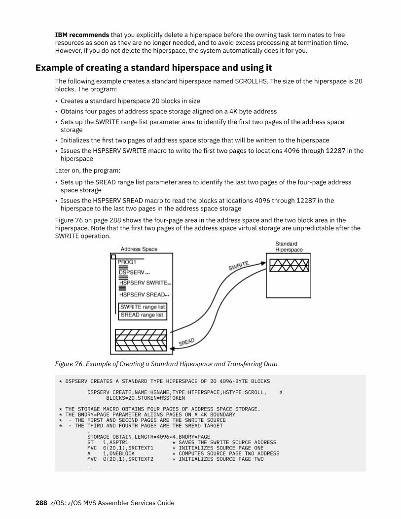
IBM recommends that you explicitly delete a hiperspace before the owning task terminates to freeresources as soon as they are no longer needed, and to avoid excess processing at termination time.However, if you do not delete the hiperspace, the system automatically does it for you.
Example of creating a standard hiperspace and using itThe following example creates a standard hiperspace named SCROLLHS. The size of the hiperspace is 20blocks. The program:
• Creates a standard hiperspace 20 blocks in size• Obtains four pages of address space storage aligned on a 4K byte address• Sets up the SWRITE range list parameter area to identify the first two pages of the address space
storage• Initializes the first two pages of address space storage that will be written to the hiperspace• Issues the HSPSERV SWRITE macro to write the first two pages to locations 4096 through 12287 in the
hiperspace
Later on, the program:
• Sets up the SREAD range list parameter area to identify the last two pages of the four-page addressspace storage
• Issues the HSPSERV SREAD macro to read the blocks at locations 4096 through 12287 in thehiperspace to the last two pages in the address space storage
Figure 76 on page 288 shows the four-page area in the address space and the two block area in thehiperspace. Note that the first two pages of the address space virtual storage are unpredictable after theSWRITE operation.
Figure 76. Example of Creating a Standard Hiperspace and Transferring Data
* DSPSERV CREATES A STANDARD TYPE HIPERSPACE OF 20 4096-BYTE BLOCKS . DSPSERV CREATE,NAME=HSNAME,TYPE=HIPERSPACE,HSTYPE=SCROLL, X BLOCKS=20,STOKEN=HSSTOKEN .* THE STORAGE MACRO OBTAINS FOUR PAGES OF ADDRESS SPACE STORAGE.* THE BNDRY=PAGE PARAMETER ALIGNS PAGES ON A 4K BOUNDARY* - THE FIRST AND SECOND PAGES ARE THE SWRITE SOURCE* - THE THIRD AND FOURTH PAGES ARE THE SREAD TARGET . STORAGE OBTAIN,LENGTH=4096*4,BNDRY=PAGE ST 1,ASPTR1 * SAVES THE SWRITE SOURCE ADDRESS MVC 0(20,1),SRCTEXT1 * INITIALIZES SOURCE PAGE ONE A 1,ONEBLOCK * COMPUTES SOURCE PAGE TWO ADDRESS MVC 0(20,1),SRCTEXT2 * INITIALIZES SOURCE PAGE TWO .
288 z/OS: z/OS MVS Assembler Services Guide

* HSPSERV WRITES TWO PAGES FROM THE ADDRESS SPACE TO THE HIPERSPACE . HSPSERV SWRITE,STOKEN=HSSTOKEN,RANGLIST=RANGPTR1 .* AFTER THE SWRITE, THE FIRST TWO ADDRESS SPACE PAGES MIGHT BE OVERLAID .
.* SET UP THE SREAD RANGE LIST TO READ INTO THE THIRD AND FOURTH* ADDRESS SPACE PAGES . L 2,ASPTR1 * OBTAINS THE ADDRESS OF PAGE 1 A 2,ONEBLOCK * COMPUTES THE SREAD TARGET ADDRESS A 2,ONEBLOCK * COMPUTES THE SREAD TARGET ADDRESS ST 2,ASPTR2 * SAVES IN SREAD RANGE LIST .
* HSPSERV READS TWO BLOCKS OF DATA FROM THE HIPERSPACE TO THE THIRD AND FOURTH PAGES IN THE ADDRESS SPACE STORAGE . HSPSERV SREAD,STOKEN=HSSTOKEN,RANGLIST=RANGPTR2 .
* DATA AREAS AND CONSTANTS*HSNAME DC CL8'SCROLLHS' * NAME FOR THE HIPERSPACEHSSTOKEN DS CL8 * STOKEN FOR THE HIPERSPACEONEBLOCK DC F'4096' * LENGTH OF ONE BLOCK OF STORAGESRCTEXT1 DC CL20' INVENTORY ITEMS 'SRCTEXT2 DC CL20' INVENTORY SURPLUSES' DS 0FRANGPTR1 DC A(SWRITLST) * ADDRESS OF THE SWRITE RANGE LISTRANGPTR2 DC A(SREADLST) * ADDRESS OF THE SREAD RANGE LIST DS 0F
SWRITLST DS 0CL12 * SWRITE RANGE LISTASPTR1 DS F * START OF ADDRESS SPACE SOURCEHSPTR1 DC F'4096' * TARGET LOCATION IN HIPERSPACENUMBLKS1 DC F'2' * NUMBER OF 4K BLOCKS IN SWRITE DS 0FSREADLST DS 0CL12 * SREAD RANGE LISTASPTR2 DS F * TARGET LOCATION IN ADDRESS SPACEHSPTR2 DC F'4096' * START OF HIPERSPACE SOURCENUMBLKS2 DC F'2' * NUMBER OF 4K PAGES IN SREAD
Using data-in-virtual with hiperspacesData-in-virtual allows you to map a large amount of data into a virtual storage area and then deal with theportion of the data that you need. The virtual storage provides a "window" through which you can "view"the object and make changes, if you want. The DIV macro manages the data object, the window, and themovement of data between the window and the object.
You can use standard hiperspaces with data-in-virtual in two ways:
• You can map a VSAM linear data set to hiperspace virtual storage.• You can map a non-shared hiperspace to virtual storage in an address space.
The task that issues the DIV IDENTIFY owns the pointers and structures associated with the ID that DIVreturns. Any program can use DIV IDENTIFY. However, the system checks the authority of programs thattry to use the other DIV services for the same ID. For problem-state programs with PSW key 8 - F, data-in-virtual allows only the issuer of the DIV IDENTIFY to use subsequent DIV services for the same ID. Thatmeans, for example, that if a problem-state program with PSW key 8 issues the DIV IDENTIFY, anotherproblem-state program with PSW key 8 cannot issue DIV MAP for the same ID.
Problem-state programs with PSW key 8 - F can use DIV MAP to:
Chapter 16. Data spaces and hiperspaces 289

• Map a VSAM linear data set to a window in a hiperspace, providing the program owns the hiperspace.• Map a non-shared hiperspace object to an address space window, providing:
– The program owns the hiperspace,– The program or its attaching task obtained the storage for the window, and– No program has ever issued ALESERV ADD for the hiperspace
The rules for using data-in-virtual and HSPSERV with the HSPALET parameter (for additionalperformance) are as follows:
• Your program can use HSPSERV with the HSPALET parameter with non-shared hiperspaces when adata-in-virtual object is mapped to a hiperspace, providing a DIV SAVE is not in effect.
• Once any program issues ALESERV ADD for a hiperspace, that hiperspace cannot be a data-in-virtualobject.
• If a program issues ALESERV ADD for a hiperspace that is currently a data object, the system rejects therequest.
For information on the use of ALETs with hiperspaces, see “Obtaining additional HSPSERV performance”on page 285.
Mapping a data-in-virtual object to a hiperspaceThrough data-in-virtual, a program can map a VSAM linear data set residing on DASD to a hiperspace. Theprogram uses the read and write operations of the HSPSERV macro to transfer data between the addressspace buffer area and the hiperspace window.
When a program maps a data-in-virtual object to a standard hiperspace, the system does not bring thedata physically into the hiperspace; it reads the data into the address space buffer when the programuses HSPSERV SREAD for that area that contains the data.
Your program can map a single data-in-virtual object to several hiperspaces. Or, it can map several data-in-virtual objects to one hiperspace.
An example of mapping a data-in-virtual object to a hiperspaceThe following example shows how you would create a standard hiperspace with a maximum size of onegigabyte and an initial size of 4K bytes. Figure 77 on page 290 shows the hiperspace with a window thatbegins at the origin of the hiperspace.
Figure 77. Example of Mapping a Data-in-Virtual Object to a Hiperspace
290 z/OS: z/OS MVS Assembler Services Guide

Initially, the window in the hiperspace and the buffer area in the address space are both 4K bytes. (Thatis, the window takes up the entire initial size of the hiperspace.) The data-in-virtual object is a VSAM lineardata set on DASD.
* CREATE A STANDARD HIPERSPACE . DSPSERV CREATE,TYPE=HIPERSPACE,HSTYPE=SCROLL,NAME=HS1NAME, X STOKEN=HS1STOK,BLOCKS=(ONEGIG,FOURK),ORIGIN=HS1ORG .
* MAP THE HIPERSPACE TO THE OBJECT . DIV IDENTIFY,ID=OBJID,TYPE=DA,DDNAME=OBJDD DIV ACCESS,ID=OBJID,MODE=UPDATE DIV MAP,ID=OBJID,AREA=HS1ORG,STOKEN=HS1STOK .* OBTAIN A 4K BUFFER AREA IN ADDRESS SPACE TO BE* USED TO UPDATE THE DATA IN THE HIPERSPACE WINDOW .* DECLARATION STATEMENTS .HS1NAME DC CL8'MYHSNAME' HIPERSPACE NAMEHS1STOK DS CL8 HIPERSPACE STOKENHS1ORG DS F HIPERSPACE ORIGINONEGIG DC F'262144' MAXIMUM SIZE OF 1G IN BLOCKSFOURK DC F'1' INITIAL SIZE OF 4K IN BLOCKSOBJID DS CL8 DIV OBJECT IDOBJDD DC AL1(7),CL7'MYDD ' DIV OBJECT DDNAME
The program can read the data in the hiperspace window to a buffer area in the address space throughthe HSPSERV SREAD macro. It can update the data and write changes back to the hiperspace through theHSPSERV SWRITE macro. For an example of these operations, see “Example of creating a standardhiperspace and using it” on page 288.
Continuing the example, the following code saves the data in the hiperspace window on DASD andterminates the mapping.
* SAVE THE DATA IN THE HIPERSPACE WINDOW ON DASD AND END THE MAPPING . DIV SAVE,ID=OBJID DIV UNMAP,ID=OBJID,AREA=HS1ORG DIV UNACCESS,ID=OBJID DIV UNIDENTIFY,ID=OBJID .* PROGRAM FINISHES USING THE DATA IN THE HIPERSPACE .* DELETE THE HIPERSPACE . DSPSERV DELETE,STOKEN=HS1STOK .
Using a hiperspace as a data-in-virtual objectYour program can identify a non-shared standard hiperspace as a temporary data-in-virtual object,providing the hiperspace has never been the target of an ALESERV ADD. In this case, the window must bein an address space. Use the hiperspace for temporary storage of data, such as intermediate results of acomputation. The movement of data between the window in the address space and the hiperspace objectis through the DIV MAP and DIV SAVE macros. The data in the hiperspace is temporary.
Figure 78 on page 292 shows an example of a hiperspace as a data-in-virtual object.
Chapter 16. Data spaces and hiperspaces 291

Figure 78. A Standard Hiperspace as a Data-in-Virtual Object
When the hiperspace is a data-in-virtual object, data-in-virtual services transfer data between thehiperspace object and the address space window. In this case, your program does not need to use, andmust not use, HSPSERV SREAD and HSPSERV SWRITE.
An example of a hiperspace as a data-in-virtual objectThe program in this information creates a hiperspace for temporary storage of a table of 4K bytes that theprogram generates and uses. The program cannot save this table permanently.
The following code creates a standard hiperspace and identifies it as a data-in-virtual object.
* CREATE A HIPERSPACE . DSPSERV CREATE,TYPE=HIPERSPACE,HSTYPE=SCROLL, X NAME=HS2NAME,STOKEN=HS2STOK,BLOCKS=ONEBLOCK .* IDENTIFY THE HIPERSPACE AS A DATA-IN-VIRTUAL OBJECT . DIV IDENTIFY,ID=OBJID,TYPE=HS,STOKEN=HS2STOK DIV ACCESS,ID=OBJID,MODE=UPDATE DIV MAP,ID=OBJID,AREA=OBJAREA .
HS2NAME DC CL8'MHSNAME ' HIPERSPACE NAMEHS2STOK DS CL8 HIPERSPACE STOKENONEBLOCK DC F'1' HIPERSPACE SIZE OF 1 BLOCKOBJID DS CL8 DIV OBJECT IDOBJAREA DS CL8 WINDOW IN ADDRESS SPACE
When the hiperspace is a data-in-virtual object, your program does not need to know the origin of thehiperspace. All addresses refer to offsets within the hiperspace. Note that the example does not includethe ORIGIN parameter on DSPSERV.
After you finish making changes to the data in the address space window, you can save the changes backto the hiperspace as follows:
* SAVE CHANGES TO THE OBJECT . DIV SAVE,ID=OBJID
The following macro refreshes the address space window. This means that if you make changes in thewindow and want a fresh copy of the object (that is, the copy that was saved last with the DIV SAVEmacro), you would issue the following:
292 z/OS: z/OS MVS Assembler Services Guide

DIV RESET,ID=OBJID
When you finish using the hiperspace, use the DSPSERV macro to delete the hiperspace.
* DELETE THE HIPERSPACE . DSPSERV DELETE,STOKEN=HS2STOK
Using checkpoint/restartA program can use checkpoint/restart while it has one or more entries for a hiperspace on its access list(DU-AL or PASN-AL). If the program has specified on the ALESERV macro that the system is to ignoreentries made to the access list for the hiperspace for checkpoint/restart processing (CHKPT=IGNORE),the CHKPT macro processes successfully.
A program that specifies CHKPT=IGNORE assumes full responsibility for managing the hiperspacestorage. Managing the hiperspace storage includes the following:
• If any program depends on the contents of the hiperspace and the data cannot be recreated or obtainedelsewhere, the responsible program must save the contents of the hiperspace prior to the checkpointoperation.
• Once the checkpoint operation has completed, the responsible program must perform the followingduring restart processing to successfully manage the hiperspace storage.
1. Ensure that the hiperspace exists. The original hiperspace might or might not exist. If the originalhiperspace does not exist, the responsible program must issue DSPSERV CREATETYPE=HIPERSPACE to recreate the hiperspace.
2. Issue ALESERV ADD of the hiperspace, original or recreated, to the program's access list to obtain anew ALET.
3. If, in addition to having a dependency on the hiperspace, any program also depends on the contentsof the hiperspace storage, the responsible program must refresh the contents of the hiperspacestorage. The program must use the new ALET to reference the hiperspace.
4. The responsible program must make the new ALET available to any program that has a dependencyon the hiperspace. The STOKEN, changed or unchanged, must be made available to any program thatneeds to issue ALESERV ADD to access the hiperspace.
See z/OS DFSMSdfp Checkpoint/Restart information about the CHKPT macro.
Chapter 16. Data spaces and hiperspaces 293

294 z/OS: z/OS MVS Assembler Services Guide
Chapter 17. Window services
Callable window services enables assembler language programs to use the CALL macro to access dataobjects. By calling the appropriate window services program, an assembler language program can:
• Read or update an existing permanent data object• Create and save a new permanent data object• Create and use a temporary data object
Window services enable your program to access data objects without your program performing any inputor output (I/O) operations. All your program needs to do is issue a CALL to the appropriate serviceprogram. The service performs any I/O operations that are required to make the data object available toyour program. When you want to update or save a data object, window services again performs anyrequired I/O operations.
Data objects
PermanentA permanent data object is a virtual storage access method (VSAM) linear data set that resides on DASD.(This type of data set is also called a data-in-virtual object.) You can read data from an existing permanentobject and also update the content of the object. You can create a new permanent object and when youare finished, save it on DASD. Because you can save this type of object on DASD, window services calls it apermanent object. Window services can handle very large permanent objects that contain as many as fourgigabytes (4294967296 bytes).
Note: Installations whose high level language programs, such as FORTRAN, used data-in-virtual objectsprior to MVS/SP 3.1.0 had to write an Assembler language interface program to allow the FORTRANprogram to invoke the data-in-virtual program. Window services eliminates the need for this interfaceprogram.
Temporary data objectsA temporary data object is an area of expanded storage that window services provides for your program.You can use this storage to hold temporary data, such as intermediate results of a computation, instead ofusing a DASD workfile. Or you might use the storage area as a temporary buffer for data that your programgenerates or obtains from some other source. When you finish using the storage area, window servicesdeletes it. Because you cannot save the storage area, window services calls it a temporary object. Windowservices can handle very large temporary objects that contain as many as 16 terabytes(17592186044416 bytes).
Structure of a data objectThink of a data object as a contiguous string of bytes organized into blocks, each 4096 bytes long. Thefirst block contains bytes 0 to 4095 of the object, the second block contains bytes 4096 to 8191, and soforth.
Your program references data in the object by identifying the block or blocks that contain the desireddata. Window services makes the blocks available to your program by mapping a window in your programstorage to the blocks. A window is a storage area that your program provides and makes known to windowservices. Mapping the window to the blocks means that window services makes the data from thoseblocks available in the window when you reference the data. You can map a window to all or part of a dataobject depending on the size of the object and the size of the window. You can examine or change datathat is in the window by using the same instructions that you use to examine or change any other data inyour program storage.
© Copyright IBM Corp. 1988, 2020 295

The following figure shows the structure of a data object and shows a window mapped to two of theobject's blocks.
Figure 79. Structure of a Data Object
What does window services provide?Window services allows you to view and manipulate data objects in a number of ways. You can haveaccess to one or more data objects at the same time. You can also define multiple windows for a givendata object. You can then view a different part of the object through each window. Before you can accessany data object, you must request access from window services.
When you request access to a permanent data object, you must indicate whether you want a scroll area. Ascroll area is an area of expanded storage that window services obtains and maps to the permanent dataobject. You can think of the permanent object as being available in the scroll area. When you request aview of the object, window services maps the window to the scroll area. If you do not request a scrollarea, window services maps the window directly to the object on DASD.
A scroll area enables you to save interim changes to a permanent object without changing the object onDASD. Also, when your program accesses a permanent object through a scroll area, your program mightattain better performance than it would if the object were accessed directly on DASD.
When you request a temporary object, window services provides an area of expanded storage. This areaof expanded storage is the temporary data object. When you request a view of the object, windowservices maps the window to the temporary object. Window services initializes a temporary object tobinary zeroes.
Note:
1. Window services does not transfer data from the object on DASD, from the scroll area, or from thetemporary object until your program references the data. Then window services transfers the blocksthat contain the data your program requests.
2. The expanded storage that window services uses for a scroll area or for a temporary object is called ahiperspace. A hiperspace is a range of contiguous virtual storage addresses that a program can use likea buffer. Window services uses as many hiperspaces as needed to contain the data object.
The ways that window services can map an objectWindow services can map a data object a number of ways. The following examples show how windowservices can:
• Map a permanent object that has no scroll area• Map a permanent object that has a scroll area• Map a temporary object• Map an object to multiple windows
296 z/OS: z/OS MVS Assembler Services Guide

• Map multiple objects
Example 1 — Mapping a permanent object that has no scroll areaIf a permanent object has no scroll area, window services maps the object from DASD directly to yourwindow. In this example, your window provides a view of the first and second blocks of an object.
Figure 80. Mapping a Permanent Object That Has No Scroll Area
Example 2 — Mapping a permanent object that has a scroll areaIf the object has a scroll area, window services maps the object from DASD to the scroll area. Windowservices then maps the blocks that you wish to view from the scroll area to your window. In this example,your window provides a view of the third and fourth blocks of an object.
Figure 81. Mapping a Permanent Object That Has A Scroll Area
Example 3 — Mapping a temporary objectWindow services uses a hiperspace as a temporary object. In this example, your window provides a viewof the first and second blocks of a temporary object.
Chapter 17. Window services 297

Figure 82. Mapping a Temporary Object
Example 4 — Mapping multiple windows to an objectWindow services can map multiple windows to the same object. In this example, one window provides aview of the second and third blocks of an object, and a second window provides a view of the last block.
Figure 83. Mapping an Object To Multiple Windows
Example 5 — Mapping multiple objectsWindow services can map multiple objects to windows in the same address space. The objects can betemporary objects, permanent objects, or a combination of temporary and permanent objects. In thisexample, one window provides a view of the second block of a temporary object, and a second windowprovides a view of the fourth and fifth blocks of a permanent object.
298 z/OS: z/OS MVS Assembler Services Guide

Figure 84. Mapping Multiple Objects
Access to permanent data objectsWhen you have access to a permanent data object, you can:
• View the object through one or more windows. Depending on the object size and the window size, asingle window can view all or part of a permanent object. If you define multiple windows, each windowcan view a different part of the object. For example, one window might view the first block of thepermanent object and another window might view the second block. You can also have several windowsview the same part of the object or have views in multiple windows overlap. For example, one windowmight view the first and second blocks of a data object while another window views the second andthird blocks.
• Change data that appears in a window. You can examine or change data that is in a window by using thesame instructions you use to examine or change any other data in your program's storage. Thesechanges do not alter the object on DASD or in the scroll area.
• Save interim changes in a scroll area. After changing data in a window, you can have window servicessave the changed blocks in a scroll area, if you have requested one. Window services replaces blocks inthe scroll area with corresponding changed blocks from the window. Saving changes in the scroll areadoes not alter the object on DASD or alter data in the window.
• Refresh a window or the scroll area. After you change data in a window or save changes in the scrollarea, you may discover that you no longer need those changes. In that case, you can have windowservices refresh the changed data. To refresh the window or the scroll area, window services replaceschanged data with data from the object as it appears on DASD.
• Replace the view in a window. After you finish using data that's in a window, you can have windowservices replace the view in the window with a different view of the object. For example, if you are
Chapter 17. Window services 299
viewing the third, fourth, and fifth blocks of an object and are finished with those blocks, you might havewindow services replace that view with a view of the sixth, seventh, and eighth blocks.
• Update the object on DASD. If you have changes available in a window or in the scroll area, you can savethe changes on DASD. Window services replaces blocks on DASD with corresponding changed blocksfrom the window and the scroll area. Updating an object on DASD does not alter data in the window or inthe scroll area.
Access to temporary data objectsWhen you have access to a temporary data object, you can:
• View the object through one or more windows. Depending on the object size and the window size, asingle window can view all or part of a temporary object. If you define multiple windows, each windowcan view a different part of the object. For example, one window might view the first block of thetemporary object and another window might view the second block. Unlike a permanent object,however, you cannot define multiple windows that have overlapping views of a temporary object.
• Change data that appears in a window. This function is the same for a temporary object as it is for apermanent object: you can examine or change data that is in a window by using the same instructionsyou use to examine or change any other data in your address space. These changes do not alter theobject on DASD or in the scroll area.
• Update the temporary object. After you have changed data in a window, you can have window servicesupdate the object with those changes. Window services replaces blocks in the object withcorresponding changed blocks from the window. The data in the window remains as it was.
• Refresh a window or the object. After you change data in a window or save changes in the object, youmay discover that you no longer need those changes. In that case, you can have window servicesrefresh the changed data. To refresh the window or the object, window services replaces changed datawith binary zeroes.
• Change the view in a window. After you finish using data that's in a window, you can have windowservices replace the view in the window with a different view of the object. For example, if you areviewing the third, fourth, and fifth blocks of an object and are finished with those blocks, you might havewindow services replace that view with a view of the sixth, seventh, and eighth blocks.
Using window servicesTo use, create, or update a data object, you call a series of programs that window services provides. Theseprograms enable you to:
• Access an existing object, create and save a new permanent object, or create a temporary object• Obtain a scroll area where you can make interim changes to a permanent object• Define windows and establish views of an object in those windows• Change or terminate the view in a window• Update a scroll area or a temporary object with changes you have made in a window• Refresh changes that you no longer need in a window or a scroll area• Update a permanent object on DASD with changes that are in a window or a scroll area• Terminate access to an object
The window services programs that you call and the sequence in which you call them depends on youruse of the data object. For descriptions of the window services, see z/OS MVS Programming: AssemblerServices Reference ABE-HSP. For an example of invoking window services from an assembler languageprogram, see “Window services coding example” on page 309.
The first step in using any data object is to gain access to the object. To gain access, you call CSRIDAC.The object can be an existing permanent object, or a new permanent or temporary object you want tocreate. For a permanent object, you can request an optional scroll area. A scroll area enables you to makeinterim changes to an object's data without affecting the data on DASD. When CSRIDAC grants access, it
300 z/OS: z/OS MVS Assembler Services Guide

provides an object identifier that identifies the object. You use that identifier to identify the object whenyou request other services from window service programs.
After obtaining access to an object, you must define one or more windows and establish views of theobject in those windows. To establish a view of an object, you tell window services which blocks you wantto view and in which windows. You can view multiple objects and multiple parts of each object at thesame time. To define windows and establish views, you call CSRVIEW or CSREVW. After establishing aview, you can examine or change data that is in the window using the same instructions you use toexamine or change other data in your program's storage.
After making changes to the part of an object that is in a window, you will probably want to save thosechanges. How you save changes depends on whether the object is permanent, is temporary, or has ascroll area.
If the object is permanent and has a scroll area, you can save changes in the scroll area without affectingthe object on DASD. Later, you can update the object on DASD with changes saved in the scroll area. If theobject is permanent and has no scroll area, you can update it on DASD with changes that are in a window.If the object is temporary, you can update it with changes that are in a window. To update an object onDASD, you call CSRSAVE. To update a temporary object or a scroll area, you call CSRSCOT.
After making changes in a window and possibly saving them in a scroll area or using them to update atemporary object, you might decide that you no longer need those changes. In this case, you can refreshthe changed blocks. After refreshing a block of a permanent object or a scroll area to which a window ismapped, the refreshed block contains the same data that the corresponding block contains on DASD.After refreshing a block of a temporary object to which a window is mapped, the block contains binaryzeroes. To refresh a changed block, you call CSRREFR.
After finishing with a view in a window, you can use the same window to view a different part of the objector to view a different object. Before changing the view in a window, you must terminate the current view.If you plan to view a different part of the same object, you terminate the current view by calling CSRVIEW.If you plan to view a different object or will not reuse the window, you can terminate the view by callingCSRIDAC.
When you finishing using a data object, you must terminate access to the object by calling CSRIDAC.
The following restrictions apply to using window services:
1. When you attach a new task, you cannot pass ownership of a mapped virtual storage window to thenew task. That is, you cannot use the ATTACH or ATTACHX keywords GSPV and GSPL to pass themapped virtual storage.
2. While your program is in cross-memory mode, your program cannot invoke data-in-virtual services;however, your program can reference and update data in a mapped virtual storage window.
3. The task that obtains the ID (through DIV IDENTIFY) is the only one that can issue other DIV servicesfor that ID.
4. When you identify a data-in-virtual object using the IDENTIFY service, you cannot request acheckpoint until you invoke the corresponding UNIDENTIFY service.
Obtaining access to a data objectTo obtain access to a permanent or temporary data object, call CSRIDAC. Indicate that you want to accessan object, by specifying BEGIN as the value for op_type.
Identifying the objectYou must identify the data object you wish to access. How you identify the object depends on whether theobject is permanent or temporary.
Permanent Object: For a permanent object, object_name and object_type work together. For object_nameyou have a choice: specify either the data set name of the object or the DDNAME to which the object isallocated. The object_type parameter must then indicate whether object_name is a DDNAME or a data setname:
Chapter 17. Window services 301

• If object_name is a DDNAME, specify DDNAME as the value for object_type.• If object_name is a data set name, specify DSNAME as the value for object_type.
If you specify DSNAME for object_type, indicate whether the object already exists or whether windowservices is to create it:
• If the object already exists, specify OLD as the value for object_state.• If window services is to create the object, specify NEW as the value for object_state.
Requirement for NEW Objects: If you specify NEW as the value for object_state, your system must includeSMS, and SMS must be active.
Temporary Object: To identify a temporary object, specify TEMPSPACE as the value for object_type.Window services assumes that a temporary object is new and must be created. Therefore, windowservices ignores the value assigned to object_state.
Specifying the object's sizeIf the object is permanent and new or is temporary, you must tell window services the size of the object.You specify object size through the object_size parameter. The size specified becomes the maximum sizethat window services will allow for that object. You express the size as the number of 4096-byte blocksneeded to contain the object. If the number of blocks needed to contain the object is not an exactmultiple of 4096, round object_size to the next whole number. For example:
• If the object size is to be less than 4097 bytes, specify 1.• If the object size is 5000 bytes, specify 2.• If the object size is 410,000 bytes, specify 101.
Specifying the type of accessFor an existing (OLD) permanent object you must specify how you intend to access the object. You specifyyour intentions through the access_mode parameter:
• If you intend to only read the object, specify READ for access_mode.• If you intend to update the object, specify UPDATE for access_mode.
For a new permanent object and for a temporary object, window services assumes you will update theobject. In these cases, window services ignores the value assigned to access_mode.
Obtaining a scroll areaA scroll area is storage that window services provides for your use. This storage is outside your program'sstorage area and is accessible only through window services.
For a permanent object, a scroll area is optional. A scroll area allows you to make interim changes to apermanent object without altering the object on DASD. Later, if you want, you can update the object onDASD with the interim changes. A scroll area might also improve performance when your programaccesses a permanent object.
For a temporary object, the scroll area is the object. Therefore, for a temporary object, a scroll area isrequired.
To indicate whether you want a scroll area, provide the appropriate value for scroll_area:
• To request a scroll area, supply a value of YES. YES is required for a temporary object.• To indicate you do not want a scroll area, supply a value of NO.
Defining a view of a data objectTo view all or part of a data object, you must provide window services with information about the objectand how you want to view it. You must provide window services with the following information:
302 z/OS: z/OS MVS Assembler Services Guide

• The object identifier• Where the window is in your address space• Window disposition — that is, whether window services is to initialize the window the first time you
reference data in the window• Whether you intend to reference blocks of data sequentially or randomly• The blocks of data that you want to view• Whether you want to extend the size of the object
To define a view of a data object, call CSRVIEW or CSREVW. To determine which service you should use,see “Defining the expected reference pattern” on page 304. Specify BEGIN as the value foroperation_type.
Identifying the data objectTo identify the object you want to view, specify the object identifier as the value for object_id. Use thesame value CSRIDAC returned in object_id when you requested access to the object.
Identifying a windowYou must identify the window through which you will view the object. The window is a virtual storage areain your address space. You are responsible for obtaining the storage, which must meet the followingrequirements:
• The storage must not be page fixed.• Pages in the window must not be page loaded (must not be loaded by the PGLOAD macro).• The storage must start on a 4096 byte boundary and must be a multiple of 4096 bytes in length.
To identify the window, use the window_name parameter. The value supplied for window_name must bethe symbolic name you assigned to the window storage area in your program.
Defining a window in this way provides one window through which you can view the object. To definemultiple windows that provide simultaneous views of different parts of the object, see “Defining multipleviews of an object” on page 305.
Defining the disposition of a window's contentsYou must specify whether window services is to replace or retain the window contents. You do this byselecting either the replace or retain option. This option determines how window services handles thedata that is in the window the first time you reference the data. You select the option by supplying a valueof REPLACE or RETAIN for disposition.
Replace optionIf you specify the replace option, the first time you reference a block to which a window is mapped,window services replaces the data in the window with corresponding data from the object. For example,assume you have requested a view of the first block of a permanent object and have specified the replaceoption. The first time you reference the window, window services replaces the data in the window withthe first 4096 bytes (the first block) from the object.
If you've selected the replace option and then call CSRSAVE to update a permanent object, or callCSRSCOT to update a scroll area, or call CSRSCOT to update a temporary object, window services updatesonly the specified blocks that have changed and to which a window is mapped.
Select the replace option when you want to examine, use, or change data that's currently in an object.
Retain optionIf you select the retain option, window services retains data that is in the window. When you reference ablock in the window the first time, the block contains the same data it contained before the reference.
Chapter 17. Window services 303

When you select the retain option, window services considers all of the data in the window as changed.Therefore, if you call CSRSCOT to update a scroll area or a temporary object, or call CSRSAVE to update apermanent object, window services updates all of the specified blocks to which a window or scroll areaare mapped.
Select the retain option when you want to replace data in an object without regard for the data that itcurrently contains. You also use the retain option when you want to initialize a new object.
Defining the expected reference patternYou must tell window services whether you intend to reference the blocks of an object sequentially orrandomly. An intention to access randomly tells window services to transfer one block (4096 bytes) ofdata into the window at a time. An intention to access sequentially tells window services to transfer morethan one block into your window at one time. The performance gain is in having blocks of data already incentral storage at the time the program needs to reference them. You specify the intent on eitherCSRVIEW or CSREVW, two services that differ on how to specify sequential access.
• CSRVIEW allows you a choice between random or sequential access.
If you specify RANDOM, when you reference data that is not in your window, window services brings inone block — the one that contains the data your program references.
If you specify SEQ for sequential, when you reference data that is not in your window, window servicesbrings in up to 16 blocks — the one that contains the data your program requests, plus the next 15consecutive blocks. The number of consecutive blocks varies, depending on the size of the window andavailability of central storage. Use CSRVIEW if you are going to do one of the following:
– Access randomly– Access sequentially, and you are satisfied with a maximum of 16 blocks coming into the window at a
time.• CSREVW is for sequential access only. It allows you to specify the maximum number of consecutive
blocks that window services brings into the window at one time. The number ranges from one blockthrough 256 blocks. Use CSREVW if you want fewer than 16 blocks or more than 16 blocks at one time.Programs that benefit from having more than 16 blocks come into a window at one time referencearrays that are greater than one megabyte. Often these programs perform significant amounts ofnumerically intensive computations.
To specify the reference pattern on CSRVIEW, supply a value of SEQ or RANDOM for usage.
To specify the reference pattern on CSREVW, supply a number from 0 through 255 for pfcount. pfcountrepresents the number of blocks window services will bring into the window, in addition to the one that italways brings in.
Note that window services brings in multiple pages differently depending on whether your object ispermanent or temporary and whether the system has moved pages of your data from central storage tomake those pages of central available for other programs. The rule is that SEQ on CSRVIEW and pfcounton CSREVW apply to:
• A permanent object when movement is from the object on DASD to central storage• A temporary object when your program has scrolled the data out and references it again.
SEQ and pfcount do not apply after the system has moved data (either changed or unchanged) to auxiliaryor expanded storage, and your program again references it, requiring the system to bring the data back tocentral storage.
End the view whether established with CSRVIEW or CSREVW, with CSRVIEW END.
Identifying the blocks you want to viewTo identify the blocks of data you want to view, use offset and span. The values you assign to offset andspan, together, define a contiguous string of blocks that you want to view:
304 z/OS: z/OS MVS Assembler Services Guide

• The value assigned to offset specifies the relative block at which to start the view. An offset of 0 meansthe first block; an offset of 1 means the second block; an offset of 2 means the third block, and so forth.
• The value assigned to span specifies the number of blocks to view. A span of 1 means one block; a spanof 2 means two blocks, and so forth. A span of 0 has special meaning: it means the view is to start at thespecified offset and extend until the currently defined end of the object.
The following table shows examples of several offset and span combinations and the resulting view in thewindow.
Offset Span Resulting view in the window
0 0 view the entire object
0 1 view the first block only
1 0 view the second block through the last block
1 1 view the second block only
2 2 view the third and fourth blocks only
Extending the size of a data objectYou can use offset and span to extend the size of an object up to the previously defined maximum size forthe object. You can extend the size of either permanent objects or temporary objects. For objects createdthrough CSRIDAC, the value assigned to object_size defines the maximum allowable size. When you callCSRIDAC to gain access to an object, CSRIDAC returns a value in high_offset that defines the current sizeof the object.
For example, assume you have access to a permanent object whose maximum allowable size is four4096-byte blocks. The object is currently two blocks long. If you define a window and specify an offset of1 and a span of 2, the window contains a view of the second block and a view of a third block which doesnot yet exist in the permanent object. When you reference the window, the content of the second block,as seen in the window, depends on the disposition you selected, replace or retain. The third block, asseen in the window, initially contains binary zeroes. If you later call CSRSAVE to update the permanentobject with changes from the window, window services extends the size of the permanent object to threeblocks by appending the new block of data to the object.
Defining multiple views of an objectYou might need to view different parts of an object at the same time. For a permanent object, you candefine windows that have non-overlapping views as well as windows that have overlapping views. For atemporary object, you can define windows that have only non-overlapping views.
• A non-overlapping view means that no two windows view the same block of the object. For example, aview is non-overlapping when one window views the first and second blocks of an object and anotherwindow views the ninth and tenth blocks of the same object. Neither window views a common block.
• An overlapping view means that two or more windows view the same block of the object. For example,the view overlaps when the second window in the previous example views the second and third blocks.Both windows view a common block, the second block.
Non-overlapping viewsTo define multiple windows that have a non-overlapping view, call CSRIDAC once to obtain the objectidentifier. Then call CSRVIEW or CSREVW once to define each window. On each call, specify BEGIN todefine the type of operation, and specify the same object identifier for object_id, and a different value forwindow_name. Define each window's view by specifying values for offset and span that create windowswith non-overlapping views.
Overlapping viewsTo define multiple windows that have an overlapping view of a permanent object, define each window asthough it were viewing a different object. That is, define each window under a different object identifier.
Chapter 17. Window services 305

To obtain the object identifiers, call CSRIDAC once for each identifier you need. Only one of the calls toCSRIDAC can specify an access mode of UPDATE. Other calls to CSRIDAC must specify an access mode ofREAD.
After calling CSRIDAC, call CSRVIEW or CSREVW once to define each window. On each call, specify BEGINto define the operation, and specify a different object identifier for object_id, and a different value forwindow_name. Define each window's view by specifying values for offset and span that create windowswith the required overlapping views.
To define multiple windows that have an overlapping view, define each window as though it were viewinga different object. That is, define each window under a different object identifier. To obtain the objectidentifiers, call CSRIDAC once for each identifier you need. Then call CSRVIEW or CSREVW once to defineeach window. On each call, specify the value BEGIN for the operation type, and specify a different objectidentifier for object_id, and a different value for window_name. Define each window's view by specifyingvalues for offset and span that create windows with the required overlapping views.
Saving interim changes to a permanent data objectWindow services allows you to save interim changes you make to a permanent object. You must havepreviously requested a scroll area for the object, however. You request a scroll area when you callCSRIDAC to gain access to the object. Window services saves changes by replacing blocks in the scrollarea with corresponding changed blocks from a window. Saving changes in the scroll area does not alterthe object on DASD.
After you have a view of the object and have made changes in the window, you can save those changes inthe scroll area. To save changes in the scroll area, call CSRSCOT. To identify the object, you must supplyan object identifier for object_id. The value supplied for object_id must be the same value CSRIDACreturned in object_id when you requested access to the object.
To identify the blocks in the object that you want to update, use offset and span. The values assigned tooffset and span, together, define a contiguous string of blocks in the object:
• The value assigned to offset specifies the relative block at which to start. An offset of 0 means the firstblock; an offset of 1 means the second block; an offset of 2 means the third block, and so forth.
• The value assigned to span specifies the number of blocks to save. A span of 1 means one block; a spanof 2 means two blocks, and so forth. A span of 0 has special meaning: it requests that window servicessave all changed blocks to which a window is mapped.
Window services replaces each block within the range specified by offset and span providing the block haschanged and a window is mapped to the block.
Updating a temporary data objectAfter making changes in a window to a temporary object, you can update the object with those changes.You must identify the object and must specify the range of blocks that you want to update. To be updated,a block must be mapped to a window and must contain changes in the window. Window services replaceseach block within the specified range with the corresponding changed block from a window.
To update a temporary object, call CSRSCOT. To identify the object, you must supply an object identifierfor object_id. The value you supply for object_id must be the same value CSRIDAC returned in object_idwhen you requested access to the object.
To identify the blocks in the object that you want to update, use offset and span. The values assigned tooffset and span, together, define a contiguous string of blocks in the object:
• The value assigned to offset specifies the relative block at which to start. An offset of 0 means the firstblock; a offset of 1 means the second block; an offset of 2 means the third block, and so forth.
• The value assigned to span specifies the number of blocks to save. A span of 1 means one block; a spanof 2 means two blocks, and so forth. A span of 0 has special meaning: it requests that window servicesupdate all changed blocks to which a window is mapped.
306 z/OS: z/OS MVS Assembler Services Guide

Window services replaces each block within the range specified by offset and span providing the block haschanged and a window is mapped to the block.
Refreshing changed dataYou can refresh blocks that are mapped to either a temporary object or to a permanent object. You mustidentify the object and specify the range of blocks you want to refresh. When you refresh blocks mappedto a temporary object, window services replaces, with binary zeros, all changed blocks that are mapped tothe window. When you refresh blocks mapped to a permanent object, window services replaces specifiedchanged blocks in a window or in the scroll area with corresponding blocks from the object on DASD.
To refresh an object, call CSRREFR. To identify the object, you must supply an object identifier forobject_id. The value supplied for object_id must be the same value CSRIDAC returned in object_id whenyou requested access to the object.
To identify the blocks of the object that you want to refresh, use offset and span. The values assigned tooffset and span, together, define a contiguous string of blocks in the object:
• The value assigned to offset specifies the relative block at which to start. An offset of 0 means the firstblock; an offset of 1 means the second block; an offset of 2 means the third block, and so forth.
• The value assigned to span specifies the number of blocks to save. A span of 1 means one block; a spanof 2 means two blocks, and so forth. A span of 0 has special meaning: it requests that window servicesrefresh all changed blocks to which a window is mapped, or refresh all changed blocks that have beensaved in a scroll area.
Window services refreshes each block within the range specified by offset and span providing the blockhas changed and a window or a scroll area is mapped to the block. At the completion of the refreshoperation, blocks from a permanent object that have been refreshed appear the same as thecorresponding blocks on DASD. Refreshed blocks from a temporary object contain binary zeroes.
Updating a permanent object on DASDYou can update a permanent object on DASD with changes that appear in a window or in the object'sscroll area. You must identify the object and specify the range of blocks that you want to update.
To update an object, call CSRSAVE. To identify the object, you must supply an object identifier forobject_id. The value you provide for object_id must be the same value CSRIDAC returned when yourequested access to the object.
To identify the blocks of the object that you want to update, use offset and span. The values assigned tooffset and span, together, define a contiguous string of blocks in the object:
• The value assigned to offset specifies the relative block at which to start. An offset of 0 means the firstblock; an offset of 1 means the second block; an offset of 2 means the third block, and so forth.
• The value assigned to span specifies the number of blocks to save. A span of 1 means one block; a spanof 2 means two blocks, and so forth. A span of 0 has special meaning: it requests that window servicesupdate all changed blocks to which a window is mapped, or update all changed blocks that have beensaved in the scroll area.
When there is a scroll areaWhen the object has a scroll area, window services first updates blocks in the scroll area withcorresponding blocks from windows. To be updated, a scroll area block must be within the specifiedrange, a window must be mapped to the block, and the window must contain changes. Window servicesnext updates blocks on DASD with corresponding blocks from the scroll area. To be updated, a DASDblock must be within the specified range and have changes in the scroll area. Blocks in the window remainunchanged.
Chapter 17. Window services 307

When there is no scroll areaWhen there is no scroll area, window services updates blocks of the object on DASD with correspondingblocks from a window. To be updated, a DASD block must be within the specified range, mapped to awindow, and have changes in the window. Blocks in the window remain unchanged.
Changing a view in a windowTo change the view in a window so you can view a different part of the same object or view a differentobject, you must first terminate the current view. To terminate the view, whether the view was establishedby CSRVIEW or CSREVW, call CSRVIEW and supply a value of END for operation_type. You must alsoidentify the object, identify the window, identify the blocks you are currently viewing, and specify adisposition for the data that is in the window.
To identify the object, supply an object identifier for object_id. The value supplied for object_id must bethe value you supplied when you established the view.
To identify the window, supply the window name for window_name. The value supplied for window_namemust be the same value you supplied when you established the view.
To identify the blocks you are currently viewing, supply values for offset and span. The values you supplymust be the same values you supplied for offset and span when you established the view.
To specify a disposition for the data you are currently viewing, supply a value for disposition. The valuedetermines what data will be in the window after the CALL to CSRVIEW completes.
• For a permanent object that has no scroll area:
– To retain the data that's currently in the window, supply a value of RETAIN for disposition.– To discard the data that's currently in the window, supply a value of REPLACE for disposition. After
the operation completes, the window contents are unpredictable.
For example, assume that a window is mapped to one block of a permanent object that has no scrollarea. The window contains the character string AAA……A and the block to which the window is mappedcontains BBB……B. If you specify a value of RETAIN, upon completion of the CALL, the window stillcontains AAA……A, and the mapped block contains BBB……B. If you specify a value of REPLACE, uponcompletion of the CALL, the window contents are unpredictable and the mapped block still containsBBB……B.
• For a permanent object that has a scroll area or for a temporary object:
– To retain the data that's currently in the window, supply a value of RETAIN for disposition. CSRVIEWor CSREVW also updates the mapped blocks of the scroll area or temporary object so that theycontain the same data as the window.
– To discard the data that's currently in the window, supply a value of REPLACE for disposition. Uponcompletion of the operation, the window contents are unpredictable.
For example, assume that a window is mapped to one block of a temporary object. The window containsthe character string AAA……A and the block to which the window is mapped contains BBB……B. If youspecify a value of RETAIN, upon completion of the CALL, the window still contains AAA……A and themapped block of the object also contains AAA……A. If you specify a value of REPLACE, upon completionof the CALL, the window contents are unpredictable and the mapped block still contains BBB……B.
CSRVIEW ignores the values you assign to the other parameters.
When you terminate the view of an object, the type of object that is mapped and the value you specify fordisposition determine whether CSRVIEW updates the mapped blocks. CSRVIEW updates the mappedblocks of a temporary object or a permanent object's scroll area if you specify a disposition of RETAIN. Inall other cases, to update the mapped blocks, call the appropriate service before terminating the view:
• To update a temporary object, or to update the scroll area of a permanent object, call CSRSCOT.• To update an object on DASD, call CSRSAVE.
308 z/OS: z/OS MVS Assembler Services Guide

Upon successful completion of the CSRVIEW operation, the content of the window depends on the valuespecified for disposition. The window is no longer mapped to a scroll area or to an object, however. Thestorage used for the window is available for other use, perhaps to use as a window for a different part ofthe same object or to use as a window for a different object.
Terminating access to a data objectWhen you finish using a data object, you must terminate access to the object. When you terminate access,window services returns to the system any virtual storage it obtained for the object: storage for atemporary object or storage for a scroll area. If the object is temporary, window services deletes theobject. If the object is permanent and window services dynamically allocated the data set when yourequested access to the object, window services dynamically unallocates the data set. Your window is nolonger mapped to the object or to a scroll area.
When you terminate access to a permanent object, window services does not update the object on DASDwith changes that are in a window or the scroll area. To update the object, call CSRSAVE beforeterminating access to the object.
To terminate access to an object, call CSRIDAC and supply a value of END for operation_type. To identifythe object, supply an object identifier for object_id. The value you supply for object_id must be the samevalue CSRIDAC returned when you obtained access to the object.
Upon successful completion of the call, the storage used for the window is available for other use,perhaps as a window for viewing a different part of the same object or to use as a window for viewing adifferent object.
Link-editing callable window servicesAny program that invokes window services must be link-edited with an IBM-provided linkage-assistroutine. The linkage-assist routine provides the logic needed to locate and invoke the callable services.The linkage-assist routine resides in SYS1.CSSLIB. The following example shows the JCL needed to link-edit a program with the linkage-assist routine.
//LINKJOB JOB 'accountinfo','name',CLASS=x,// MSGCLASS=x,NOTIFY=userid,MSGLEVEL=(1,1),REGION=4096K//LINKSTP1 EXEC PGM=HEWL,PARM='LIST,LET,XREF,REFR,RENT,NCAL,// SIZE=(1800K,128K)'//SYSPRINT DD SYSOUT=x//SYSLMOD DD DSNAME=userid.LOADLIB,DISP=SHR//SYSUT1 DD UNIT=SYSDA,SPACE=(TRK,(5,2))//SYSLIN DD * INCLUDE OBJDD1(userpgm) LIBRARY OBJDD2(CSRIDAC,CSRREFR,CSREVW,CSRSCOT,CSRSAVE,CSRVIEW) NAME userpgm(R)//OBJDD1 DD DSN=userid.OBJLIB,DISP=SHR//OBJDD2 DD DSN=SYS1.CSSLIB,DISP=SHR
The example JCL assumes that the program you are link-editing is reentrant.
Window services coding exampleThis example shows the code needed to invoke window services from an assembler language program.Use this example to supplement and reinforce information that is presented elsewhere in this chapter.
EXAMPLE1 CSECT STM 14,12,12(13) Save caller's registers in caller's* save area LR 12,15 Set up R12 as the base register USING EXAMPLE1,12* .* .* .********************************************************************* Set up save area *********************************************************************
Chapter 17. Window services 309

LA 15,SAVEAREA Load address of save area into R15 ST 13,4(15) Save address of caller's save area* into this program's save area ST 15,8(13) Save address of this program's save* area into caller's save area LR 13,15 Load address of save area into R13* .* . Program continues....* .********************************************************************* Call CSRIDAC to identify and access an old data object, request ** a scroll area, and get update access. ********************************************************************* CALL CSRIDAC,(OPBEGIN,DDNAME,OBJNAME,YES,OLD,ACCMODE, * OBJSIZE,OBJID1,LSIZE,RC,RSN)* .* . Program continues....* .********************************************************************* Get 50 pages of virtual storage to use as a window ********************************************************************* STORAGE OBTAIN,LENGTH=GSIZE,BNDRY=PAGE,ADDR=WINDWPTR L R3,WINDWPTR Move the address of the window into* register 3 USING WINDOW,R3 Sets up WINDOW as based off of reg 3********************************************************************* Call CSRVIEW to set up a map of 50 blocks between the virtual ** storage obtained through the STORAGE macro and the data object. ********************************************************************* LA R4,ZERO LOAD A ZERO INTO REGISTER 4 ST R4,OFFSET1 Initialize offset to 0 to indicate* the beginning of the data object CALL CSRVIEW,(OPBEGIN,OBJID1,OFFSET1,SPAN1,(R3),ACCSEQ, * REPLACE,RC,RSN)* .* . Program continues....* . write data in the window* .
********************************************************************* Call CSRSAVE to write data in the window to the first 50 blocks ** of the data object ********************************************************************* CALL CSRSAVE,(OBJID1,OFFSET1,SPAN1,LSIZE,RC,RSN)* .* . Program continues....* . change data in the window* .********************************************************************* Call CSRSCOT to write new data in the window to the first 50 ** blocks of the scroll area ********************************************************************* CALL CSRSCOT,(OBJID1,OFFSET1,SPAN1,RC,RSN)* .* . Program continues....* . change data in the window* .********************************************************************* Call CSRREFR to refresh the window, that is, get back the last ** SAVEd data in the data object ********************************************************************* CALL CSRREFR,(OBJID1,OFFSET1,SPAN1,RC,RSN)* .* . Program continues....* .********************************************************************* Call CSRIDAC to unidentify and unaccess the data object ********************************************************************* CALL CSRIDAC,(OPEND,DDNAME,OBJNAME,YES,OLD,ACCMODE, * OBJSIZE,OBJID1,LSIZE,RC,RSN)* .* . Program continues....* . L 13,SAVEAREA+4 LM 14,12,12(13) BR 14 End of EXAMPLE1ZERO EQU 0 Constant zeroGSIZE EQU 204800 Storage for window of 50 pages (blocks)R3 EQU 3 Register 3R4 EQU 4 Register 4 DS 0D
310 z/OS: z/OS MVS Assembler Services Guide
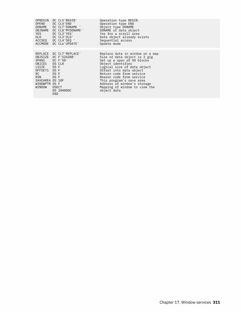
OPBEGIN DC CL5'BEGIN' Operation type BEGINOPEND DC CL4'END ' Operation type ENDDDNAME DC CL7'DDNAME ' Object type DDNAMEOBJNAME DC CL8'MYDDNAME' DDNAME of data objectYES DC CL3'YES' Yes for a scroll areaOLD DC CL3'OLD' Data object already existsACCSEQ DC CL4'SEQ ' Sequential accessACCMODE DC CL6'UPDATE' Update mode
REPLACE DC CL7'REPLACE' Replace data in window on a mapOBJSIZE DC F'524288' Size of data object is 2 gigSPAN1 DC F'50' Set up a span of 50 blocksOBJID1 DS CL8 Object identifierLSIZE DS F Logical size of data objectOFFSET1 DS F Offset into data objectRC DS F Return code from serviceRSN DS F Reason code from serviceSAVEAREA DS 18F This program's save areaWINDWPTR DS F Address of window's storageWINDOW DSECT Mapping of window to view the DS 204800C object data END
Chapter 17. Window services 311

312 z/OS: z/OS MVS Assembler Services Guide

Chapter 18. Sharing application data (name/tokencallable services)
Name/token callable services allow you to share data between two programs running under the sametask, or between two or more tasks or address spaces. To share data, programs often need to locate dataor data structures acquired and built by other programs. These data structures and the programs usingthem need not reside in the same address space. Name/token callable services provide a way forprograms to save and retrieve the information needed to locate this data.
Both unauthorized (problem state and PSW key 8-15) and authorized programs (supervisor state or PSWkey 0-7) can use name/token callable services. Name/token callable services provide additional functionthat is available to authorized programs only. For a description of those functions, see z/OS MVSProgramming: Authorized Assembler Services Guide.
Understanding name/token pairs and levelsName/token callable services enable programs to save and retrieve 16 bytes of application-related data.A program can associate a 16-byte character string (the name) with 16 bytes of user data (the token).Later, the same or a different program can retrieve the token by using the name and calling a name/tokenservice.
By using the appropriate name/token callable service, a program can:
• Create a name/token pair (IEANTCR)• Retrieve a token from a name/token pair (IEANTRT)• Delete a name/token pair (IEANTDL).
Name/token pairsA name/token pair consists of a 16-byte character string (name) with 16 bytes of user data (token). Oneprogram creates the name/token pair, assigns the name, and initializes the token field. Typically, the tokenis an address of a data structure.
Figure 85 on page 313 shows the name/token pair and indicates its intended use.
Figure 85. Using the Name and the Token
The bytes of the name can have any hexadecimal value and consist of alphabetic or numeric characters.The name may contain blanks, integers, or addresses.
Names must be unique within a level. Here are some examples.
• Two task-level name/token pairs owned by the same task cannot have the same name. However, twotask-level name/token pairs owned by different tasks can have the same name.
© Copyright IBM Corp. 1988, 2020 313

• Two home-address-space-level name/token pairs in the same address space cannot have the samename. However, two home-address-space-level name/token pairs in different address spaces can havethe same name.
Because of these unique requirements you must avoid using the same names that IBM uses for name/token pairs. Do not use the following names:
• Names that begin with A through I• Names that begin with X'00'.
The token can have any value.
Levels for name/token pairsName/token pairs have a level attribute associated with them. The level defines the relationship of thecreating program (that is, the program that creates the name/token pair) to the retrieving program (that is,the program that retrieves the data). Depending on the level you select, the retrieving program can rununder the same task as the creating program, or in the same home address space, in the same primaryaddress space, or in the same system.
• A task-level name/token pair allows the creating program and retrieving program to run under thesame task.
• A home-address-space-level name/token pair allows the creating program and the retrieving programto run in the same home address space.
• A primary-address-space-level name/token pair allows the creating program and the retrievingprogram to run in the same primary address space.
• A system-level name/token pair allows the creating program and the retrieving program to run in thesame system. That is, the two programs run in separate address spaces.
The various name/token levels allow for sharing data between programs that run under a single task,between programs that run within an address space, and between programs that run in different addressspaces. Some examples of using name/token levels are:
• Different programs that run under the same task can share data through the use of a task-level pair.• Any number of tasks that run within an address space can share data through the use of an address-
space pair.
Determining what your program can do with name/token pairsThe following table shows the name/token callable services your program can use to manipulate differentlevels of name/token pairs:
Table 29. Summary of What Programs Do with Name/Token Pairs
Service Level of pairs
Create (IEANTCR) • Task• Home• Primary
Retrieve (IEANTRT) • Task• Home• Primary• System
314 z/OS: z/OS MVS Assembler Services Guide

Table 29. Summary of What Programs Do with Name/Token Pairs (continued)
Service Level of pairs
Delete (IEANTDL) • Task• Home• Primary
Note: Unauthorized programs cannot delete any pairs created byauthorized programs.
Note: The primary-address-space-level and system-level name/token pairs are intended to be used in across-memory environment established by authorized programs. For complete descriptions of theprimary-level and system-level name/token pairs, see z/OS MVS Programming: Authorized AssemblerServices Guide.
Deciding what name/token level you needTo determine the level to use, consider the relationship between the code that creates the pair and thecode that retrieves the pair:
• If the retrieving code will be running under the same task as the creator's code, use the task level• If the retrieving code will have the same home address space but run under a different task, use the
home address space level.
Task-level name/token pairA task-level name/token pair can be used to anchor data that relates to only one task. Your applicationprogram can create and retrieve the data as often as needed.
Figure 86 on page 315 shows the task-level name/token pair for TASK 1.
Figure 86. Using the Task Level in a Single Address Space
In a single address space, TASK 1:
1. Creates the task-level name/token pair (N1,T1) using the IEANTCR callable service.2. Retrieves the token at a later time by calling its name (N1) using the IEANTRT callable service.
Chapter 18. Sharing application data (name/token callable services) 315

3. Deletes the name/token pair by calling its name (N1) using the IEANTDL callable service.
Home-level name/token pairA home-level name/token pair can anchor data for use by programs running in the creating program'shome address space.
Figure 87 on page 316 shows the name/token pairs associated with TASK 1 and TASK 2 running in theaddress space.
Figure 87. Using Home-Level and Task-Level Name/Token Pairs
In Figure 87 on page 316, TASK 1:
1. Creates a task-level name/token pair (N1,T1) and a home-level name/token pair (N2,T2) using theIEANTCR callable service. The home-level name/token pair is associated with the address space.
2. Retrieves the token from N1,T1 any time during the task's processing.
TASK 2 does the following:
1. Retrieves the home-level token from N2,T2 that was created by TASK 1. TASK 2 can retrieve that tokenbecause both tasks are running in the same home address space.
316 z/OS: z/OS MVS Assembler Services Guide

2. Creates its own home-level name/token pair (N3,T3) that other tasks running in the home addressspace can access.
Owning and deleting name/token pairsName/token pairs created by a program are automatically deleted by the system. The level of the pairdetermines when the system deletes the pair:
Note: The words job step in this topic refers to the cross memory resource owning (CMRO) task. While theCMRO task is generally the main job step task, at times it may be either the initiator task or started taskcontrol task (such as between jobs).
• Task-level pairs are owned by the task that created them and are deleted when the owning taskterminates.
• Home-address-space-level name/token pairs are owned by the job step task of the home addressspace that created them and are deleted when the job step task, rather than the creating task, in theaddress space terminates; that is, home-level pairs created by subtasks of a task are not automaticallydeleted when the subtask terminates.
• Primary-address-space-level name/token pairs are owned by the job step task of the primary addressspace that created them and are deleted when the job step task, rather than the creating task, in theaddress space terminates; that is, primary-level pairs created by subtasks of a task are notautomatically deleted when the subtask terminates.
Using checkpoint/restart with name/token pairsA program cannot complete a checkpoint operation, by issuing the CHKPT macro, if certain name/tokenpairs are owned by the program at the time of the checkpoint. The pairs are:
• Task-level name/token pairs not created with a persist_option value of 2 are owned by the task issuingthe CHKPT macro.
• Home- or primary-address-space-level name/token pairs owned by the job step task of the homeaddress space of the task issuing the CHKPT macro.
A checkpoint fails if task- or address-space-level pairs exist because the information in the pairs is notsaved in the checkpoint data set when the checkpoint is taken. Because the pair information is not saved,the program cannot be restored when the restart occurs. For more information about checkpoint/restart,see z/OS DFSMSdfp Checkpoint/Restart.
Link-editing name/token servicesA program that calls the name/token services must be link-edited with IBM-provided name/tokenlinkage-assist routines. The linkage-assist routines reside in SYS1.CSSLIB. The following example showsthe JCL that can link-edit a reentrant program with the linkage-assist routines:
//userid JOB 'accounting-info','name',CLASS=x,// MSGCLASS=x,NOTIFY=userid,MSGLEVEL=(1,1),REGION=4096K//LINKSTEP EXEC PGM=HEWL,// PARM='LIST,LET,XREF,REFR,RENT,SIZE=(1800K,128K)'//SYSPRINT DD SYSOUT=x//SYSLMOD DD DSN=userid.LOADLIB,DISP=OLD//SYSLIB DD DSN=SYS1.CSSLIB,DISP=SHR//OBJLIB DD DSN=userid.OBJLIB,DISP=SHR//SYSUT1 DD UNIT=SYSDA,SPACE=(TRK,(5,2))//SYSLIN DD * INCLUDE OBJLIB(userpgm) ENTRY userpgm NAME userpgm(R)/*
Chapter 18. Sharing application data (name/token callable services) 317

318 z/OS: z/OS MVS Assembler Services Guide

Chapter 19. Processor storage management
The system administers the use of processor storage (that is, central and expanded storage) and it directsthe movement of virtual pages between auxiliary, expanded, and central storage in page size (4096 byteor 4 K-byte) blocks. It makes all addressable virtual storage in each address space and data space orhiperspace appear as central storage. Virtual pages necessary for program execution are kept inprocessor storage while:
• The program references the pages frequently enough• Other programs do not need that same central storage.
The system performs the paging I/O necessary to transfer pages in and out of central storage and alsoprovides DASD allocation and management for paging I/O space on auxiliary storage.
The system assigns real frames upon request from a pool of available real frames, which associatesvirtual addresses with real addresses. A limit on the number of real frames that can be used by an addressspace is related to its virtual storage limits and its memory limits. For more information on these limits,see the Chapter 11, “Virtual storage management,” on page 189 section and the z/OS MVS Initializationand Tuning Guide. Frames are repossessed upon termination of use, when freed by a user, when a user isswapped-out, or when needed to replenish the available pool. While a virtual page occupies a real frame,the page is considered pageable unless specified otherwise as a system page that must be resident incentral storage. The system also allocates virtual equals central (V=R) regions upon request by thoseprograms that cannot tolerate dynamic relocation. Such a region is allocated contiguously from apredefined area of central storage and is not pageable. Programs in this region do run in dynamic addresstranslation (DAT) mode, although real and virtual addresses are equivalent.
This chapter describes how you can:
• Free the virtual storage in your address space and the virtual storage in any data space that you mighthave access to
– FREEMAIN and STORAGE RELEASE frees specific portions of virtual storage in address spaces.– DSPSERV DELETE frees all of the virtual storage in a data space or hiperspace.
• Release the central and expanded storage that holds the data that your program has in virtual storage.
– PGRLSE or PGSER RELEASE releases specified portions of virtual storage contents of an addressspace.
– DSPSERV RELEASE releases specified portions of virtual storage contents of a data space orhiperspace.
• Request that a range of virtual storage pages be made read-only or be made modifiable.
– PGSER PROTECT allows the caller to request that a range of virtual storage pages be made read-only.– PGSER UNPROTECT allows the caller to request that a range of virtual storage pages be made
modifiable.• Request that the system preload or page out central storage
– PGLOAD or PGSER LOAD loads specified virtual storage areas of an address space into centralstorage.
– PGOUT or PGSER OUT pages out specified virtual storage areas of an address space from centralstorage.
– DSPSERV LOAD loads specified virtual storage areas of a data space into central storage.– DSPSERV OUT pages out specified virtual storage areas of a data space from central storage.
• Request that the system preload multiple pages on a page fault.
– REFPAT causes the system to preload pages according to a program's reference pattern. REFPAT isintended for numerically intensive programs.
© Copyright IBM Corp. 1988, 2020 319

Freeing virtual storageAll storage obtained for your program by GETMAIN, STORAGE OBTAIN, or DSPSERV CREATE isautomatically freed by the system when the job step terminates. Freeing storage in this manner requiresno action on your part.
FREEMAIN or STORAGE RELEASE perform the equivalent of a page release for any resulting free page.The page is no longer available to the issuer. FREEMAIN can free a page that has been protected throughthe PGSER macro with the PROTECT option. DSPSERV DELETE performs the same action for a data spacethat FREEMAIN and STORAGE RELEASE do for address space virtual storage except that for a data spaceor hiperspace, all of the storage is released.
Releasing storageWhen your program is finished using an area of virtual storage, it can release the storage to make thecentral, expanded, or auxiliary storage that actually holds the data available for other uses. The decisionto release the storage depends on the size of the storage and when the storage will be used again:
• For large areas (over 100 pages, for example) that will not be used for five or more seconds of processortime, consider releasing the storage. If you do not release those pages after you are finished usingthem:
– Your program might be using central storage that could better be used for other purposes.– Your program might have delays later when the system moves your pages from central storage to
expanded or auxiliary storage.• Generally, for smaller amounts of storage that will be used again in five seconds or less, do not release
the storage.
Note that releasing storage does not free the virtual storage.
When releasing storage for an address space, use PGRLSE or PGSER with the RELEASE parameter. Asshown in Figure 88 on page 320, if the specified addresses are not on page boundaries, the low address isrounded up and the high address is rounded down; then, the pages contained between the addresses arereleased.
Note: PGRLSE, PGSER RELEASE, PGSER FREE with RELEASE=Y, and PGFREE RELEASE=Y may ignoresome or all of the pages in the input range and will not notify the caller if this was done.
Any pages in the input range that match any of the following conditions will be skipped, and processingcontinues with the next page in the range:
• Storage is not allocated or all pages in a segment have not yet been referenced.• Page is in PSA, SQA or LSQA.• Page is V=R. Effectively, it's fixed.• Page is in BLDL, (E)PLPA, or (E)MLPA.• Page has a page fix in progress or a nonzero FIX count.• Pages with COMMIT in progress or with DISASSOCIATE in progress.
Figure 88. Releasing Virtual Storage
320 z/OS: z/OS MVS Assembler Services Guide

When releasing storage for a data space or hiperspace, use the DSPSERV RELEASE macro to releasethe central, expanded or auxiliary storage that actually holds the data. PGSER RELEASE rejects anyattempt to release protected storage, including storage that is dynamically protected through PGSERPROTECT. The starting address must be on a 4K-byte boundary and you can release data space storageonly in increments of 4K bytes.
For both address spaces and data spaces, the virtual space remains, but its contents are discarded. Whenthe using program can discard the contents of a large virtual area (one or more complete pages) and reusethe virtual space without the necessity of paging operations, the page release function may improveoperating efficiency.
Protecting a range of virtual storage pagesThe PROTECT option of PGSER makes a range of virtual storage pages read-only and helps to improvedata integrity. The UNPROTECT option of PGSER makes a range of virtual storage pages modifiable. Youcan protect private storage both above and below 16 megabytes.
IBM recommends that you use PGSER PROTECT only for full pages of storage on page boundaries. Thisusage avoids making other areas of storage read-only unintentionally. For instance, if you obtain a virtualstorage area smaller than a page and then issue PGSER PROTECT, the entire page is made read-only,including the portion of the page that is not part of your storage area.
The system does not keep track of how many times a page has been protected or unprotected. OneUNPROTECT cancels all PROTECTs for a given page.
Loading/paging out virtual storage areasThe PGLOAD, PGSER LOAD, and DSPSERV LOAD essentially provide a page-ahead function. By loadingspecified address space and data space areas into central storage, you can attempt to ensure that certainpages will be in central storage when needed. Page faults can still occur, however, because these pagesmay be paged out if not referenced soon enough.
Loading and paging for address spaces: With the page load function, you have the option of specifying thatthe contents of the virtual area is to remain intact or be released. If you specify RELEASE=Y with PGLOADor PGSER LOAD, the current contents of entire virtual 4K pages to be brought in may be discarded andnew real frames assigned without page-in operations; if you specify RELEASE=N, the contents are toremain intact and be used later. If you specify RELEASE=Y, the page release function will be performedbefore the page load function. That is, no page-in is needed for areas defining entire virtual pages sincethe contents of those pages are expendable.
Note: PGRLSE, PGSER RELEASE, PGSER FREE with RELEASE=Y, and PGFREE RELEASE=Y may ignoresome or all of the pages in the input range and will not notify the caller if this was done.
Any pages in the input range that match any of the following conditions will be skipped, and processingcontinues with the next page in the range:
• Storage is not allocated or all pages in a segment have not yet been referenced.• Page is in PSA, SQA or LSQA.• Page is V=R. Effectively, it's fixed.• Page is in BLDL, (E)PLPA, or (E)MLPA.• Page has a page fix in progress or a nonzero FIX count.• Pages with COMMIT in progress or with DISASSOCIATE in progress.
Loading and paging for data spaces: DSPSERV LOAD requests the starting address of the data space areato be loaded and the number of pages that the system is to load. It does not offer a RELEASE=Y or aRELEASE=N function.
PGOUT, PGSER OUT, and DSPSERV OUT initiate page-out operations for specified virtual areas that are incentral storage. For address spaces, the real frames will be made available for reuse upon completion ofthe page-out operation unless you specify the KEEPREL parameter in the macro. An area that does not
Chapter 19. Processor storage management 321

encompass one or more complete pages will be copied to auxiliary storage, but the real frames will not befreed. DSPSERV LOAD does not have the KEEPREL function.
The proper use of the page load and page out functions tend to decrease system overhead by helping thesystem keep pages currently in use, or soon to be in use, in central storage. An example of the misuse ofthe page load function is to load ten pages and then use only two.
For more information on DSPSERV LOAD and DSPSERV OUT, see “Paging data space storage areas intoand out of central storage” on page 273.
Virtual subarea listThe virtual subarea list (VSL) provides the basic input to the page service functions that use a 24-bitinterface: PGLOAD, PGRLSE, and PGOUT. The list consists of one or more doubleword entries, with eachentry describing an area of virtual storage. The list must be non-pageable and contained in the addressspace of the subarea to be processed.
Each VSL entry has the following format. The flag bits that are described are the only flag bits that areintended for customer use.
Table 30. Format of a virtual subarea list (VSL) entry
Byte: 0 1 2 3 4 5 6 7
Contents: Flags StartAddress
Flags EndAddress + 1
ByteContents
Byte 0Flags:Bit
Meaning when set1... ....
Bit 0 indicates that bytes 1 - 3 are a chain pointer to the next VSL entry to be processed; bytes 4-7are ignored. This feature allows several parameter lists to be chained as a single logical parameterlist.
Byte 1Start address: The address of the origin of the virtual area to be processed.
Byte 3FlagsBit
Meaning when set1... ....
Bit 0 indicates the last entry of the list. It is set in the last doubleword entry in the list..1.. ....
Bit 1 indicates that this entry is to be ignored....1 ....
Bit 3 indicates that a return code of 4 was issued from a page service function other than PGRLSE.Byte 4
End address + 1: The address of the byte immediately following the end of the virtual area.
322 z/OS: z/OS MVS Assembler Services Guide

Page service list (PSL)The page services list provides the basic input to the page service function for the PGSER macro. Specify31-bit addresses in the PSL entries. Within a PSL entry, you can also nullify a service on a range ofaddresses by indicating that you do not want to perform the service for that range.
Each 12-byte PSL entry has the following form:Bytes
Meaning0-3
Bit 0 of byte 0 must be 0. Each PSL entry specifies the range of addresses for which a service is to beperformed or points to the first PSL entry in a new list of concatenated PSL entries that are to beprocessed.
4-7Bit 0 of byte 4 must be 0. If bytes 0-3 contain the starting address, these bytes contain the address ofthe last byte for which the page service is to be performed. You do not need to do anything with bytes4-7 if you supplied a pointer in bytes 0-3.
8Flags set by the caller as follows. The flag bits that are described are the only flag bits intended forcustomer use.Bit
Meaning0
Set to 1 to indicate that this is the last PSL entry in a concatenation of PSL entries.1
Set to 1 to indicate that no services are to be performed for the range of addresses specified.2
Set to 1 to indicate that bytes 0-3 contain a pointer to the next PSL.9-11
For IBM use only.
Defining the reference pattern (REFPAT)The REFPAT macro allows a program to define a reference pattern for a specified area that the program isabout to reference. Additionally, the program specifies how much data it wants the system to attempt tobring into central storage on a page fault. The system honors the request according to the availability ofcentral storage. By bringing in more data at a time, the system takes fewer page faults; fewer page faultsmeans possible improvement in performance.
Programs that benefit from REFPAT are those that reference amounts of data that are greater than onemegabyte. The program should reference the data in a sequential manner, either forward or backward. Inaddition, if the program "skips over" certain areas, and these areas are of uniform size and are repeated atregular intervals, REFPAT might provide additional performance improvement. Although REFPAT affectsmovement of pages from auxiliary and expanded storage, the greatest gain is for movement of pages fromauxiliary storage.
There are two REFPAT services:
• REFPAT INSTALL identifies the data area and the reference pattern, and specifies the number of bytesthat the system is to try to bring into central storage at one time. These activities are called "defining thereference pattern".
• REFPAT REMOVE removes the definition; it tells the system that the program has stopped using thereference pattern for the specified data area.
Chapter 19. Processor storage management 323

A program might have a number of different ways of referencing a particular area. In this case, theprogram can issue multiple pairs of REFPAT INSTALL and REFPAT REMOVE macros for that area.
Each pattern, as defined on REFPAT INSTALL, is associated with the task that represents the caller. A taskcan have up to 100 reference patterns defined for multiple data areas at one time, but cannot have morethan one pattern defined for the same area. Other tasks can specify a different reference pattern for thesame data area. REFPAT REMOVE removes the association between the pattern and the task.
The data area can be in the primary address space or in a data space owned by a task that was dispatchedin the primary address space. If the data area is in a data space, identify the data space through itsSTOKEN. You received the STOKEN either from DSPSERV or from another program.
Although REFPAT can be used for data structures other than arrays, for simplicity, examples in thischapter use REFPAT for an array or part of an array.
Reference pattern services for high-level language (HLL) and assembler language programs providefunction similar to what REFPAT offers. For information about these services, see z/OS MVS Programming:Callable Services for High-Level Languages.
How does the system handle the data in an array?To evaluate the performance advantage REFPAT offers, you need to understand how the system handles arange of data that a program references. Consider the two-dimensional array in Figure 89 on page 324that is shown in row-major order and in order of increasing addresses. This array has 1024 columns and1024 rows and each element is eight bytes in size. Each number in Figure 89 on page 324 represents oneelement. The size of the array is 1048576 elements for a total of 8388608 bytes. For simplicity, assumethe array is aligned on a page boundary. Assume, also, that the array is not already in central storage. Theprogram references each element in the array in a forward direction (that is, in order of increasingaddresses) starting with the first element in the array.
Figure 89. Example of using REFPAT with a Large Array
First, consider how the system brings data into central storage without using the information REFPATprovides. At the first reference of the array, the system takes a page fault and brings into central storagethe page (of 4096 bytes) that contains the first element. After the program finishes processing the 512thelement (4096 divided by 8) in the array, the system takes another page fault and brings in a second page.To provide the data for this program, the system takes two page faults for each row. The following linearrepresentation shows the elements in the array and the page faults the system takes as the programprocesses through the array.
324 z/OS: z/OS MVS Assembler Services Guide

By bringing in one page at a time, the system takes 2048 page faults (8388608 divided by 4096), eachpage fault adding to the elapsed time of the program.
Suppose, through REFPAT, the system knew in advance that a program would be using the array in aconsistently forward direction. The system could then assume that the program's use of the pages of thearray would be sequential. To decrease the number of page faults, each time the program requested datathat was not in central storage, the system could bring in more than one page at a time. Suppose thesystem brought the next 20 consecutive pages (81920 bytes) of the array into central storage on eachpage fault. In this case, the system takes not 2048 page faults, but 103 (8388608 divided by81920=102.4). Page faults occur in the array as follows:
The system brings in successive pages only to the end of the array.
Consider another way of referencing this same array. The program references the first twenty elements ineach row, then skips over the last 1004 elements, and so forth through the array. REFPAT allows you totell the system to bring in only the pages that contain the data in the first 20 columns of the array, and notthe pages that contain only data in columns 21 through 1024. In this case, the reference pattern includesa repeating gap of 8032 bytes (1004×8) every 8192 bytes (1024×8). The pattern looks like this:
The grouping of consecutive bytes that the program references is called a reference unit. The grouping ofconsecutive bytes that the program skips over is called a gap. Reference units and gaps alternatethroughout the data area. The reference pattern is as follows:
• The reference unit is 20 elements in size — 160 consecutive bytes that the program references.• The gap is 1004 elements in size — 8032 consecutive bytes that the program skips over.
Figure 90 on page 326 illustrates this reference pattern and shows the pages that the system does notbring into central storage.
What pages does the system bring in when a gap exists?When no gap exists, the system brings into central storage all the pages that contain the data in the rangeyou specify on REFPAT. When there is a gap, the answer depends on the size of the gap, the size of thereference unit, and the alignment of reference units and gaps on page boundaries. The followingexamples illustrate those factors.
Example 1: The following illustration shows the 1024-by-1024 array of eight-byte elements, where theprogram references the first 20 elements in each row and skips over the next 1004 elements. Thereference pattern, therefore, includes a reference unit of 160 bytes and a gap of 8032 bytes. Thereference units begin on every other page boundary.
Chapter 19. Processor storage management 325

Figure 90. Illustration of a Reference Pattern with a Gap
Every other page of the data does not come into central storage; those pages contain only the "skippedover" data.
Example 2: The reference pattern includes a reference unit of 4800 bytes and a gap of 3392 bytes. Theexample assumes that the area to be referenced starts on a page boundary.
Because each page contains data that the program references, the system brings in all pages.
Example 3: The area to be referenced does not begin on a page boundary. The reference pattern includesa reference unit of 2000 bytes and a gap of 5000 bytes. Because the reference pattern includes a gap, thefirst byte of the reference pattern must begin a reference unit, as the following illustration shows:
Because the gap is larger than 4095 bytes, some pages do not come into central storage. Notice that thesystem does not bring in the fifth page.
Summary of how the size of the gap affects the pages the system brings into central storage:
• If the gap is less than 4096 bytes, the system has to bring into central storage all pages of the array.(See Example 2.)
• If the gap is greater than 4095 bytes and less than 8192, the system might not have to bring in certainpages. Pages that contain only data in the gap are not brought in. (See Examples 1 and 3.)
• If the gap is greater than 8191 bytes, the system definitely does not have to bring in certain pages thatcontain the gap.
Using the REFPAT macroOn the REFPAT macro, you tell the system:
• The starting and ending addresses of the data area to be referenced• The reference pattern• The number of reference units the system is to bring into central storage on a page fault.
326 z/OS: z/OS MVS Assembler Services Guide

Specify the reference pattern carefully on REFPAT. If you identify a pattern and do not adhere to it, thesystem will have to work harder than if you had not issued the macro. “Defining the reference pattern” onpage 328 can help you define the reference pattern.
The system will not process the REFPAT macro unless the values you specify can result in a performancegain for your program. To make sure the system processes the macro, ask the system to bring in morethan three pages (that is, 12288 bytes) on each page fault. “Choosing the number of bytes on a pagefault” on page 329 can help you meet that requirement.
Identifying the data area and direction of referenceOn the PSTART and PEND parameters, you specify the starting and ending addresses of the area to bereferenced. If the reference is in a backward direction, the ending address will be smaller than thestarting address.
PSTART identifies the first byte of the data area that the program references with the defined pattern;PEND identifies the last byte.
When a gap exists, define PSTART and PEND according to the following rules:
• If direction is forward, PSTART must be the first byte (low-address end) of a reference unit; PEND can beany part of a reference unit or a gap.
• If direction is backward, PSTART must be the last byte (high-address end) of a reference unit; PEND canbe any part of a reference unit or a gap.
Figure 91 on page 327 illustrates a reference pattern that includes a reference unit of 2000 bytes and agap of 5000 bytes. When direction is forward, PSTART must be the beginning of a reference unit. PENDcan be any part of a gap or reference unit.
Figure 91. Illustration of Forward Direction in a Reference Pattern
Figure 92 on page 327 illustrates the same reference pattern and the same area; however, the direction isbackward. Therefore, PSTART must be the last byte of a reference unit and PEND can be any part of a gapor reference unit.
Figure 92. Illustration of Backward Direction in a Reference Pattern
If the data area is in a data space, use the STOKEN parameter to identify the data space. You received theSTOKEN of the data space from another program or from the DSPSERV macro when you created the dataspace. STOKEN=0, the default, tells the system that the data is in the primary address space.
Chapter 19. Processor storage management 327

Defining the reference patternThis information assumes that your program's reference pattern meets the basic requirement ofconsistent direction. Figure 93 on page 328 identifies tw o reference patterns that characterize most ofthe reference patterns that REFPAT applies to. The marks on the line indicate referenced elements.
Figure 93. Two Typical Reference Patterns
How you define the reference pattern depends on whether your program's reference pattern is likePattern #1 or Pattern #2.
• With Pattern #1 where no uniform gap exists, the program uses every element, every other element,or at least most elements on each page of array data. No definable gap exists. Do not use REFPAT if thereference pattern is irregular and includes skipping over many areas larger than a page.
– The UNITSIZE parameter alone identifies the reference pattern. (Either omit the GAP parameter ortake the default, GAP=0.) UNITSIZE indicates the number of bytes you want the system to use as areference unit. Look at logical groupings of bytes, such as one row, a number of rows, or one element,if the elements are large in size. Or, you might choose to divide up the total area, bringing in all thedata on a certain number of page faults.
– The UNITS parameter tells the system how many reference units to try to bring in on a page fault. Fora reference pattern that begins on a page boundary and has no gap, the total number of bytes thesystem tries to bring into central storage at a time is the value on UNITSIZE times the number onUNITS, rounded up to the nearest multiple of 4096. See “Choosing the number of bytes on a pagefault” on page 329 for more information on how to choose the total number of bytes.
• With Pattern #2 where a uniform gap exists, you tell the system the sizes of reference units and gaps.
– UNITSIZE and GAP parameters identify the reference pattern. Pattern #2 in Figure 93 on page 328includes a reference unit of 20 bytes and a gap of 5000 bytes. Because the gap is greater than 4095,some pages of the array might not come into central storage.
– The UNITS parameter tells the system how many reference units to try to bring into central storage ata time. “What pages does the system bring in when a gap exists?” on page 325 can help youunderstand how many bytes come into central storage at one time.
Although the system brings in pages 4096 bytes at a time, you do not have to specify GAP, UNITS, andUNITSIZE values in increments of 4096.
328 z/OS: z/OS MVS Assembler Services Guide

Choosing the number of bytes on a page faultAn important consideration in using REFPAT is how many bytes to ask the system to bring in on a pagefault. To determine this, you need to understand some factors that affect the performance of yourprogram.
Pages do not stay in central storage if they are not referenced frequently enough and other programs needthat central storage. The longer it takes for a program to begin referencing a page in central storage, thegreater the chance that the page has been moved out to auxiliary storage before being referenced. Whenyou tell the system how many bytes it should try to bring into central at one time, you have to consider thefollowing:
1. Contention for central storage
Your program contends for central storage along with all other submitted jobs. The greater the size ofcentral storage, the more bytes you can ask the system to bring in on a page fault. The systemresponds to REFPAT with as much of the data you request as possible, given the availability of centralstorage.
2. Contention for processor time
Your program contends for the processor's attention along with all other submitted jobs. The morecompetition, the less the processor can do for your program and the smaller the number of bytes youshould request.
3. The elapsed time of processing one page of your data
How long it takes a program to process a page depends on the number of references per page and theelapsed time per reference. If your program uses only a small percentage of elements on a page andreferences them only once or twice, the program completes its use of pages quickly. If the processingof each referenced element includes processor-intensive operations or a time-intensive operation,such as I/O, the time the program takes to process a page gets longer.
Conditions might vary between the peak activity of the daytime period and the low activity of otherperiods. For example, you might be able to request a greater number in the middle of the night thanduring the day.
What if you specify too many bytes? What if you ask the system to bring in so many pages that, by the timeyour program needs to use some of those pages, they have left central storage? The answer is that thesystem will have to bring them in again. This action causes an extra page fault and extra system overheadand reduces the benefit of reference pattern services.
For example, suppose you ask the system to bring in 204800 bytes, or 50 pages, at a time. But, by thetime your program begins referencing the data on the 30th page, the system has moved that page and theones after it out of central storage. (It moved them out because the program did not use them soonenough.) In this case, your program has lost the benefit of moving the last 21 pages in. Your programwould get more benefit by requesting fewer than 30 pages.
What if you specify too few bytes? If you specify too small a number, the system will take more page faultsthan it needs to and you are not taking full advantage of reference pattern services.
For example, suppose you ask the system to bring in 40960 bytes (10 pages) at a time. Your program'suse of each page is not time-intensive, meaning that the program finishes using the pages quickly. Theprogram can request a number greater than 10 without causing additional page faults.
IBM recommends that you use one of the following approaches, depending on whether you want toinvolve your system programmer in the decision.
• The first approach is the easier one. Choose a conservative number of bytes, around 81920 (20 pages),and run the program. Look for an improvement in the elapsed time. If you like the results, you mightincrease the number of bytes. If you continue to increase the number, at some point you will notice adiminishing improvement or even an increase in elapsed time. Do not ask for so much that your programor other programs suffer from degraded performance.
• A second approach is for the program that needs very significant performance improvements — thoseprograms that require amounts in excess of 50 pages. If you have such a program, you and your system
Chapter 19. Processor storage management 329

programmer must examine the program's elapsed time, paging speeds, and processor execution times.In fact, the system programmer can tune the system with your program in mind and provide neededpaging resources. See z/OS MVS Initialization and Tuning Guide for information on tuning the system.
REFPAT affects movement of pages from auxiliary and your system programmer will need the kind ofinformation that the SMF Type 30 record provides. A Type 30 record reports counts of pages moved(between expanded and central and between auxiliary and central) in anticipation of your program's useof those pages. It also provides elapsed time values. Use this information to calculate rates ofmovement in determining whether to specify a very large number of bytes — for example, an amountgreater than 204800 bytes (50 pages).
Examples of using REFPAT to define a reference patternTo clarify the relationships between the UNITSIZE, UNITS, and GAP parameters, this information containsthree examples of defining a reference pattern. So that you can compare the three examples with whatthe system does without information from REFPAT, the following REFPAT invocation approximates thesystem's normal paging operation:
REFPAT INSTALL,PSTART=. . .,PEND=. . .,UNITSIZE=4096,GAP=0,UNITS=1
Each time the system takes a page fault, it brings in 4096 bytes, the system's reference unit. It brings inone reference unit at a time.
Example 1: The program processes an array in a consistently forward direction from one reference unit tothe next. The processing of each element is fairly simple. The program runs during the peak hours andmany programs compete for processor time and central storage. A reasonable value to choose for thenumber of bytes to be brought into central storage on a page fault might be 80000 bytes (around 20pages). A logical grouping of bytes (the UNITSIZE parameter) is 4000 bytes. The following REFPAT macrocommunicates this pattern to the system:
REFPAT INSTALL,PSTART=FIRSTB,PEND=LASTB,UNITSIZE=4000,GAP=0,UNITS=20
Example 2: The program performs the same process as in the first example, except the programreferences few elements on each page. The program runs during the night hours when contention for theprocessor and for central storage is light. In this case, a reasonable value to choose for the number ofbytes to come into central storage on a page fault might be 200000 bytes (around 50 pages). UNITSIZEcan be 4000 bytes and UNITS can be 500. The following REFPAT macro communicates this pattern:
REFPAT INSTALL,PSTART=FIRSTB,PEND=LASTB,UNITSIZE=4000,GAP=0,UNITS=500
Example 3: The program references in a consistently forward direction through the same large array as inthe second example. The pattern of reference includes a gap. The program references 8192 bytes, thenskips the next 4096 bytes, references the next 8192 bytes, skips the next 4096 bytes, and so forththroughout the array. The program chooses to bring in data eight pages at a time. Because of the size ofthe gap and the placement of reference units and gaps on page boundaries, the system does not bring inthe data in the gaps. The following illustration shows this reference pattern:
The following REFPAT macro reflects this reference pattern:
REFPAT INSTALL,PSTART=FIRSTB,PEND=LASTB,UNITSIZE=8192,GAP=4096,UNITS=4
where the system is to bring into central storage 32768 (4×8192) bytes on a page fault.
330 z/OS: z/OS MVS Assembler Services Guide

Removing the definition of the reference patternWhen a program is finished referencing the data area in the way you specified on the REFPAT INSTALLmacro, use REFPAT REMOVE to tell the system to return to normal paging. On the PSTART and PENDparameters, you specify the same values that you specified on the PSTART and PEND parameters thatdefined the reference pattern for the area. If you used the STOKEN parameter on REFPAT INSTALL, use iton REFPAT REMOVE.
The following REFPAT invocation removes the reference pattern that was defined in Example 3 in“Examples of using REFPAT to define a reference pattern” on page 330:
REFPAT REMOVE,PSTART=FIRSTB,PEND=LASTB
Chapter 19. Processor storage management 331

332 z/OS: z/OS MVS Assembler Services Guide

Chapter 20. Sharing data in virtual storage(IARVSERV macro)
With the shared pages function, which is available through the IARVSERV macro, you can define virtualstorage areas through which data can be shared by programs within or between address spaces or dataspaces. Also, the type of storage access can be changed.
Sharing reduces the amount of processor storage required and the I/O necessary to support dataapplications that require access to the same data. For example, IARVSERV provides a way for a programrunning below 16 megabytes, in 24-bit addressing mode, to access data above 16 megabytes that itshares with 31-bit mode programs. IARVSERV allows the sharing of data without the central storageconstraints and processor overhead of other existing methods of sharing data.
The sharing of data benefits many types of applications, because data is available to all sharingapplications with no increase in storage usage. This function is useful for applications in either a sysplexenvironment or a single-system environment. Additionally, IARVSERV allows you to control whether asharing program:
• Has read access only• Has both read and write access and receives updates immediately• Can modify the data without modifying the original, and without allowing the sharing programs to view
the updates• Can modify the original while sharing programs see the change, but without allowing the sharing
programs to change the data• Can change the current storage access
An additional macro, IARR2V, is provided as an aid to converting central storage addresses to virtualstorage addresses. See “Converting a central to virtual storage address (IARR2V macro)” on page 340 forinformation on the IARR2V macro.
The IARVSERV topics described in this chapter are:
• Understanding the concepts of sharing data with IARVSERV• Storage you can use with IARVSERV• Obtaining storage for the source and target• Defining storage for sharing data and access• Changing storage access• How to share and unshare data• Accessing data in a sharing group• Example of sharing storage with IARVSERV• Use with data-in-virtual (DIV macro)• Diagnosing problems with shared data
For coding information about the IARVSERV and IARR2V macros, see z/OS MVS Programming: AssemblerServices Reference IAR-XCT.
Understanding the concepts of sharing data with IARVSERVAs you read this information, refer to Figure 94 on page 334 for an illustration of the sharing data throughthe IARVSERV macro.
© Copyright IBM Corp. 1988, 2020 333

Figure 94. Data Sharing with IARVSERV
Suppose that Addr Space A contains data that is required by programs in Addr Space B. A program in AddrSpace A can use IARVSERV to define that data to be shared; that data and the storage it resides in arecalled the source. The program also defines storage in Addr Space B to receive a copy of the source; thatstorage and its copy of source data are called the target.
The source and its corresponding target form a sharing group. A sharing group can consist of severaltarget areas and one source. For example, suppose another program in Addr Space A defines a portion ofdata1 (in Addr Space A) as source, and defines a target in Data Space X. That target becomes a member ofthe sharing group established previously.
All sharing of data is done on a page (4K) basis. If the source page is already a member of an existingsharing group, the target becomes a member of that existing sharing group. A page is called a sharingpage if it is a member of a sharing group.
Programs that access the source or targets are called sharing programs. Each sharing program accessesthe shared virtual storage as it would any other storage, and may not need to know that the storage isbeing shared. So, you can allow programs to share data through IARVSERV without having to rewriteexisting programs.
Storage you can use with IARVSERVYou can share data in address spaces and data spaces. You can use any storage to which you have validaccess, except for a hiperspace, a VIO window, a V=R region, the PSA or the nucleus (read-only, extendedread-only, read-write and extended read-write areas).
The maximum number of shared pages for a program in problem state with PSW key 8-15 is 32, unlessthis number is modified by your installation. This number includes both the source and targets, so theactual number of unique pages is 16.
In order to expedite the return of all internal control blocks for the shared storage back to the system,IBM recommends issuing IARVSERV UNSHARE against all views for both source and target that areoriginally shared. For an example of how to code the UNSHARE parameter, see z/OS MVS Programming:Assembler Services Reference IAR-XCT.
Obtaining storage for the source and targetBefore you can issue IARVSERV to define storage as shared, you must obtain or create both the sourceand target areas. For address space storage, use the GETMAIN or STORAGE macro; for data spacestorage, use the DSPSERV macro. The source and target areas must be as follows:
• Start on a page boundary,
334 z/OS: z/OS MVS Assembler Services Guide

• Have the same storage protect key and fetch-protection status (except forTARGET_VIEW=UNIQUEWRITE or TARGET_VIEW=LIKESOURCE and the source has UNIQUEWRITEview),
• Meet one of the following requirements:
– Reside within pageable private storage of an address space.– Reside within the valid size of an existing data space and be pageable storage.
The source and the target must be two different storage areas. They must be different virtual storageaddresses or reside in different address or data spaces.
Then initialize the source with data. Make sure any storage you obtain or data space you create can beaccessed by the intended sharing programs. For example, if you want to allow sharing programs to bothread and modify a target, the programs' PSW key value must match or override the target's storageprotection key. For information on data spaces, see Chapter 16, “Data spaces and hiperspaces,” on page261.
Note: Do not allocate key 8 or key 9 storage in the common area because it can be read or written by anyprogram in any address space.
Defining storage for sharing data and accessWith the IARVSERV macro, you can define multiple types of data sharing and access. As you read thisinformation, use Figure 94 on page 334 to see how each IARVSERV parameter acts on the current state ofthe data. Each type of data sharing access is called a specific view of the source data. A view is the wayyour program accesses, or sees, the data. You define the view in the TARGET_VIEW parameter onIARVSERV, by specifying one of the following:
• Read-only view (READONLY value) — where the target data may not be modified.• Shared-write view (SHAREDWRITE value) — where the target data can be read and modified through the
view.• Copy-on-write view (UNIQUEWRITE value) — where the source data modifications are not seen by other
source - sharing programs. Any attempt to modify the shared source data in this view causes MVS tocreate a unique target copy of the affected page for that address or data space.
An example of two different cases:
– If the shared data is modified through a SHAREDWRITE view, the UNIQUEWRITE view gets anunmodified copy of the data. Any remaining views sharing that data see the modified data.
– If the shared data is modified through a UNIQUEWRITE view, the UNIQUEWRITE view gets themodified copy of the data. Any remaining views sharing that data see the unmodified data.
• Copy-on-write target view (TARGETWRITE value) — where the target data may be read and modifiedthrough the source view. Any modification of a shared target page causes MVS to create a unique targetcopy of the affected page for that address or data space.
An example for two different cases:
– If the shared data is modified through a SHAREDWRITE view, the TARGETWRITE view sees themodified data.
– If the shared data is modified through a TARGETWRITE view, the TARGETWRITE view sees themodified copy of the data. Any remaining views sharing that data see the unmodified data.
• Like source view (LIKESOURCE value) — where the target data is given the current view type of thesource data. If the source data is currently not shared, then its current storage attribute is given to thetarget.
• Hidden view (HIDDEN value) — where the target will share the source data, but any attempt to accessthe target data (HIDDEN value) will cause a program check. To access the target, the view type must bechanged to READONLY, SHAREDWRITE, UNIQUEWRITE, or TARGETWRITE.
When you specify a value for TARGET_VIEW, keep the following in mind:
Chapter 20. Sharing data in virtual storage (IARVSERV macro) 335

• The execution key (PSW key) of the caller must be sufficient for altering the target area. IfTARGET_VIEW=SHAREDWRITE is specified, the execution key must be sufficient for altering the sourcearea also.
• For TARGET_VIEW=UNIQUEWRITE, if the input source area is address space storage, and the storagehas not been obtained by GETMAIN or STORAGE OBTAIN, or the storage and fetch protect keys do notmatch, then the SHARE is not performed for that area. The target will be all zeros (first reference), or itwill remain as pages that were not obtained by GETMAIN.
• For target views created with LIKESOURCE on IARVSERV SHARE, the system propagates explicit pageprotection from the source to the target view.
• Page-fixed pages and DREF pages cannot be made TARGETWRITE, UNIQUEWRITE, or HIDDEN.
Changing storage accessWith the IARVSERV macro, the SHARE and CHANGEACCESS parameters can change the views type ofstorage access. For SHARE, the current storage attribute of the source data affects the outcome of thetarget. Table 31 on page 336 shows the permitted target views for different combinations with the source.A NO in the table means that an abend will occur if you request that target view with the current sourceview. For CHANGEACCESS, all combinations are permitted.
Table 31. Allowed Source/Target View Combinations for Share
Current Requested Target View
Source View READONLY SHAREDWRITE UNIQUEWRITE TARGETWRITE HIDDEN LIKESOURCE
READONLY Yes No Yes Yes Yes Yes
SHAREDWRITE Yes Yes Yes Yes Yes Yes
UNIQUEWRITE Yes Yes Yes Yes Yes Yes
TARGETWRITE No No Yes No No Yes
HIDDEN (Shared) No No No No No Yes
Non-Shared Yes Yes Yes Yes Yes Yes
HIDDEN (Non-Shared) No No No No No Yes
The following apply when using IARVSERV SHARE when changing storage access:
• For source views to be either UNIQUEWRITE or TARGETWRITE, the processor must have theSuppression-On-Protection (SOP) hardware feature, and a previous IARVSERV SHARE must havecreated a view of UNIQUEWRITE or TARGETWRITE.
• For target views to be TARGETWRITE, the processor must have the SOP hardware feature. If a request ismade to create a TARGETWRITE view and the SOP feature is not installed, the request fails with a returncode of 8.
• For target views to be UNIQUEWRITE, the SOP hardware feature must be installed. Also, the requestmust not specify COPYNOW. If the request specifies COPYNOW, or the SOP feature is not installed, aUNIQUEWRITE view is not established, and a separate copy of the data is made.
• For target views created with LIKESOURCE on IARVSERV SHARE, the system propagates explicit pageprotection from the source to the target view.
• For source pages that are not shared, if the page is page-protected, the view created for that page is aSHAREDWRITE view, but the view is flagged as an explicitly protected view (one that cannot bemodified).
The following apply when changing the storage access with IARVSERV CHANGEACCESS:
• To remove hidden status, you must use an IARVSERV CHANGEACCESS, FREEMAIN, or DSPSERVDELETE macro.
• To remove explicit read-only protection status, you must use an IARVSERV CHANGEACCESS,FREEMAIN, DSPSERV DELETE, or PGSER UNPROTECT macro.
336 z/OS: z/OS MVS Assembler Services Guide

• If a hidden page is hidden because of loss of access to 'mapped' data (such as through DIV UNMAP),and, if the page is changed from hidden, the data in the page might be lost.
• Hidden pages cannot be released via a PGSER RELEASE or DSPSERV RELEASE macro. An attempt wouldresult in an abend with the same reason code as is used for protected pages.
• Issuing an IARVSERV UNSHARE macro for the original mapped page causes the data to be retained forthat page. The data for the other sharing pages is lost. References to hidden pages cause an X'0C4'abend, and references to lost pages cause in a X'028' abend.
• Page-fixed pages and DREF pages cannot be made TARGETWRITE, UNIQUEWRITE, or HIDDEN.
How to share and unshare dataWith the IARVSERV macro, use the SHARE parameter to initiate sharing of data; use the UNSHAREparameter to end sharing for the issuing program. This information discusses the additional IARVSERVparameters that you can specify with SHARE or UNSHARE.
The RANGLIST parameter is always required for both SHARE and UNSHARE. It gives IARVSERVinformation about the source and target addresses. The RANGLIST value is actually the address of the listof addresses you must create using the mapping macro IARVRL. For the details of IARVRL, see z/OS MVSData Areas in the z/OS Internet library (www.ibm.com/servers/resourcelink/svc00100.nsf/pages/zosInternetLibrary). The following table lists the required IARVRL fields that you must supply for SHAREor UNSHARE.
IARVRL Fields That You Must Initialize forSHARE
IARVRL Fields That You Must Initialize forUNSHARE
VRLSVSAVRLSSTKN (for STOKEN)VRLSALET (for ALET)VRLNUMPGVRLTVSAVRLTSTKN (for STOKEN)VRLTALET (for ALET)
VRLNUMPGVRLTVSAVRLTSTKN (for STOKEN)VRLTAKET (for ALET)
For IARVSERV SHARE, if the target area contains pages that belong to an existing sharing group, MVSperforms an implicit UNSHARE to pull those pages out of the existing sharing group before proceeding.Also, MVS automatically performs an UNSHARE on any sharing page when the page is being freed byFREEMAIN, STORAGE RELEASE, or DSPSERV DELETE, or when the page's address space is ended.
Also, when MVS finds that one page of a range is not acceptable for sharing, MVS will not complete theSHARE request for that page, nor the rest of the range or ranges not already processed. You can assumethat all pages up to that point were processed successfully. An abend will be issued and GPR 2 and 3 willcontain the address range list associated with the error page and the storage address of the page in error,respectively. To remove the SHARE on the successful pages, issue IARVSERV UNSHARE for the storageranges up to, but excluding, the error page.
The parameter TARGET_VIEW is required with SHARE only, to tell IARVSERV how you plan to share thedata contained in the source. You have three choices described in “Defining storage for sharing data andaccess” on page 335.
• READONLY does not allow any program accessing the target area to write to it. An abend results if aprogram attempts to write to a READONLY target.
• SHAREDWRITE allows any sharing program to write to the target. All those sharing the target areainstantly receive the updates. This view could be very useful as a communication method for programs.
• UNIQUEWRITE has the property of copy-on-write, which means that MVS creates a copy of a page forthe updating program once the program writes to that page. The only program that has the change is theprogram that changed it; all others continue to use the original page unmodified. This is true whetherthe program writes to a source or target page.
Chapter 20. Sharing data in virtual storage (IARVSERV macro) 337
A copy-on-write hardware facility is provided for additional performance improvement. If you need todetermine if your processor has the feature, you can use the CVT mapping macro, and test the CVTSOPFbit. For details on the CVT mapping macro, see z/OS MVS Data Areas in the z/OS Internet library(www.ibm.com/servers/resourcelink/svc00100.nsf/pages/zosInternetLibrary).
RETAIN is a parameter available only with UNSHARE. RETAIN=NO requests that MVS remove the targetfrom sharing. The target data is lost. RETAIN=YES requests that MVS leave the data in the targetuntouched.
Accessing data in a sharing groupData is accessed in a sharing group just as it would be if sharing did not exist. Trying to write to aREADONLY view will cause an abend.
You can create a sharing group that permits programs in 24-bit addressing mode to access data above 16megabytes. To do this, you would define the source in storage above 16 megabytes, and obtain a target instorage below 16 megabytes. Then initialize the source with data, so programs in 24-bit mode can sharethe data through the target.
Example of sharing storage with IARVSERVSuppose you are updating a program called PGMA, that controls all the account deposits for a savingsbank. Your program must work with two older programs that are complex and do not have source codeavailable. The first program, called SUBPGMA, was updated six years ago and runs in 31-bit addressingmode; it records deposits in money market accounts. It cannot use data spaces. The other program,SUBPGMB, is much older and records deposits in standard savings accounts. It runs in 24-bit addressingmode. See Figure 95 on page 339 for a representation of the storage.
Program PGMA, the main program, was written to keep all of its data in one large data space. PGMA mustcontinually obtain appropriate storage in the address space that is addressed by SUBPGMA andSUBPGMB. After SUBPGMA and SUBPGMB finish, PGMA must copy all the updated data back to the dataspace. This is degrading performance and needs to be fixed. By using IARVSERV, you can eliminate thecopying, and reduce the complexity of PGMA.
Your update to PGMA would cause the programs to work together this way:
1. PGMA creates a data space and initializes it with data.2. Before PGMA calls SUBPGMA to do a money market deposit, PGMA issues GETMAIN for storage in the
private area for a buffer. This buffer is BUFFER31.3. PGMA issues IARVSERV SHARE to share the source in the data space with the target, BUFFER31. Use
TARGET_VIEW=SHAREDWRITE so updates can be made directly into the data space.4. PGMA now calls SUBPGMA to update the data, passing the address of BUFFER31 as the area to be
updated.5. Once SUBPGMA updates the data in BUFFER31, PGMA issues IARVSERV UNSHARE followed by
FREEMAIN to release the storage.6. When PGMA needs to call SUBPGMB to do a savings account deposit, the only difference is that PGMA
must obtain storage below 16 megabytes for the buffer. This buffer is BUFFER24.7. PGMA again issues IARVSERV SHARE with TARGET_VIEW=SHAREDWRITE, but identifies the target as
BUFFER24.8. PGMA calls SUBPGMB to update the data, passing the address of BUFFER24 as the area to be
updated.9. Once SUBPGMB updates the data in BUFFER24, PGMA issues IARVSERV UNSHARE and FREEMAIN to
release the storage as before.
Note that all three programs could share the data in the data space at the same time. Sharing continuesuntil PGMA issues IARVSERV UNSHARE for that buffer area.
338 z/OS: z/OS MVS Assembler Services Guide

Figure 95. Sharing Storage with IARVSERV
Use with data-in-virtual (DIV macro)There are several restrictions for programs that use data-in-virtual MAP service with data shared usingthe IARVSERV SHARE service:
• A sharing page must reside in non-swappable storage and have a SHAREDWRITE view mode.• Only one member of a sharing group can be mapped. Any attempt to map another member of the same
sharing group results in a X'08B' abend.• You cannot use the IARVSERV macro to share data mapped to a hiperspace object.• You cannot map a sharing page whose sharing group contains a page that is currently a fixed or disabled
reference page.• If the owning address space of a sharing page that was mapped by DIV MAP terminates prior to a DIV
UNMAP, the data is lost. Any further reference to the shared data results in a X'028' abend.
There are also restrictions for programs that use the data-in-virtual UNMAP function.
If a sharing page is currently mapped, and the owner of the map issues DIV UNMAP with RETAIN for thatpage, the value of RETAIN affects all sharing group members as follows:
• For RETAIN=NO, all pages of the target become unpredictable in content.• For RETAIN=YES, all pages of the target get the data as it last appeared within the sharing page. This
can be useful for saving an instance of data, such as a check point. Use of RETAIN=YES can affectperformance if it consumes large amounts of central storage by repeated retaining of the storage.
Diagnosing problems with shared dataYou can use IPCS reports to see how data is being shared through IARVSERV. The IPCS RSMDATAsubcommand with the SHRDATA parameter provides a detailed report on the status of IARVSERV datasharing. The following RSMDATA reports also provide shared data information: ADDRSPACE, EXPFRAME,REALFRAME, RSMREQ, SUMMARY, and VIRTPAGE. See z/OS MVS IPCS Commands for more informationabout the SHRDATA subcommand.
You may also collect information about data shared through IARVSERV by issuing the DISPLAY command,and by specifying certain optional parameters on the IARR2V macro. See z/OS MVS System Commandsand “Converting a central to virtual storage address (IARR2V macro)” on page 340 for more information.
Chapter 20. Sharing data in virtual storage (IARVSERV macro) 339

Converting a central to virtual storage address (IARR2V macro)The IARR2V macro provides a simple method to obtain a virtual storage address from a central storageaddress. This conversion can be useful, for example, when you are working with an I/O or diagnosticprogram that provides central storage addresses, but you want to use virtual storage addresses.
The details of the syntax and parameters of IARR2V are in z/OS MVS Programming: Assembler ServicesReference IAR-XCT. In its simplest form, the IARR2V macro requires only the RSA parameter. The RSAparameter specifies the central storage address that you want to convert.
The system returns the virtual storage address in a register or in a storage location you specify throughthe VSA parameter. Also, you can request the system to return the ASID or STOKEN of the address spaceor data space associated with the address.
If you require knowledge of whether the central storage address you have is being shared through theIARVSERV macro, you can get that information using the WORKREG, NUMVIEW, and NUMVALIDparameters. To use the NUMVIEW and NUMVALID parameters, you must use the WORKREG parameter tospecify the work register for the system to use. The NUMVIEW parameter requests the total number ofpages sharing the view of your central storage address. NUMVALID requests the number of pagescurrently addressable (accessed), which is called the number of valid views. With NUMVIEW andNUMVALID, you can check how effectively programs are using shared storage. Pages that are notaccessed have not been read or updated by any program.
340 z/OS: z/OS MVS Assembler Services Guide

Chapter 21. Timing and communication
This chapter describes timing services and communication services. Use timing services to determinewhether the basic or extended time-of-day (TOD) clock is synchronized with an External Time Referencehardware facility (ETR2), obtain the present date and time, convert date and time information to variousformats, or for interval timing. Interval timing lets you set a time interval, test how much time is left in theinterval, or cancel the interval. Use communication services to send messages to the system operator, toTSO/E terminals, and to the system log.
Checking for timer synchronizationSeveral processors can share work in a data processing complex. Each of these processors has access toa TOD clock. Thus, when work is shared among different processors, multiple TOD clocks can be involved.However, these clocks might not be synchronized with one another. The External Time Reference (ETR) isa single external time source that can synchronize the TOD clocks of all processors in a complex.
For programs that are dependent upon synchronized TOD clocks in a multi-system environment, it isimportant that the clocks are in ETR synchronization. Use the STCKSYNC macro to obtain the TOD clockcontents and determine if the clock is synchronized with an ETR. STCKSYNC also provides an optionalparameter, ETRID, that returns the ID of the ETR source with which the TOD clock is currentlysynchronized.
Note: IBM recommends the use of the STCKSYNC macro instead of the STCK instruction for all multi-system programs that are dependent upon synchronized clocks.
Obtaining time of day and dateWhen an ETR is used, the time of day and date are set automatically at system initialization. In otherconfigurations, the operator is responsible for initially supplying the correct time of day and date in termsof a 24-hour clock.
You can use the TIME macro to obtain the time of day and date for programs that require this information.If you specify ZONE=UTC or GMT with TIME, the returned time of day and date will be for UniversalCoordinated Time. If you specify ZONE=LT or omit the ZONE parameter, the TIME macro returns the localtime of day and date. However, if you specify STCK or STCKE, the ZONE parameter has no meaning. Whenyou specify LINKAGE=SYSTEM with the TIME macro, you can select the format for the returned date byusing the DATETYPE parameter.
All references to time of day use the time-of-day (TOD) clock, either the basic format (unsigned 64-bitbinary number) or the extended format (unsigned 128-bit binary number). The TOD clock runscontinuously while the power is on, and the clock is not affected by system-stop conditions. Normally, theclock is reset only when an interruption of processor power has caused the clock to stop, and restorationof power has restarted the clock at a later time. When an ETR is used, the clock reset happensautomatically; in other configurations, the operator resets the clock. (For more information about the TODclock, see Principles of Operation.)
Converting between time of day and date and TOD clock formatsYou can use the STCKCONV macro to convert a TOD clock value to time of day and date, specifying theformat in which the information will be returned. This conversion is useful, for example, for producing areport that requires the time and date to be printed in a certain format.
You can use the CONVTOD macro to convert a time of day and date value to TOD or ETOD clock format.The macro accepts a time of day and date value in any of the formats returned by the STCKCONV andTIME macros, and converts that value to either TOD clock format.
2 External time reference (ETR) is the MVS generic name for the IBM Sysplex Timer.
© Copyright IBM Corp. 1988, 2020 341

It is recommended that you begin to convert your applications to using the ETOD format. The extendedtime-of-day format was required both to address the time wrapping problem that would occur in the year2042 and also to provide inproved resolution necessary for the faster processors as they becomeavailable.
Note that if you request ETOD information and your processor is not configured with the 128-bit extendedtime-of-day clock, timer services will return the contents of the 64-bit TOD and will simulate theremaining 64 bits of the ETOD. Conversely, if you request TOD information and your processor isconfigured with the extended time-of-day clock, timer services will return only that portion of the 128-bitETOD that corresponds to the 64-bit TOD.
Interval timingTime intervals can be established for any task in the job step through the use of the STIMER or STIMERMSET macros. The time remaining in an interval established via the STIMER macro can be tested orcancelled through the use of TTIMER macro. The time remaining in an interval established via theSTIMERM SET macro can be cancelled or tested through the use of the STIMERM CANCEL or STIMERMTEST macros.
The value of the CPU timer can be obtained by using the CPUTIMER macro. The CPU timer is used to tracktask-related time intervals.
The TASK, REAL, or WAIT parameters of the STIMER macro and the WAIT=YES|NO parameter of theSTIMERM SET macro specify the manner in which the time interval is to be decreased. REAL and WAITindicate the interval is to be decreased continuously, whether the associated task is active or not. TASKindicates the interval is to be decreased only when the associated task is active. STIMERM SET canestablish real time intervals only.
If REAL or TASK is specified on STIMER or WAIT=NO is specified on STIMERM SET, the task continues tocompete with the other ready tasks for control; if WAIT is specified on STIMER, or WAIT=YES is specifiedon STIMERM SET, the task is placed in a WAIT condition until the interval expires, at which time the task isplaced in the ready condition.
When TASK or REAL is specified on STIMER or WAIT=NO is specified on STIMERM SET, the address of anasynchronous timer completion exit routine can also be specified. This routine is given control sometimeafter the time interval completes. The delay is dependent on the system's work load and the relativedispatching priority of the associated task. If an exit routine is not specified, there is no notification of thecompletion of the time interval. The exit routine must be in virtual storage when specified, must save andrestore registers as well as return control to the address in register 14.
Timing services does not serialize the use of asynchronous timer completion routines.
When you cancel a timer request that specified a timer exit:
1. Specify the TU or MIC parameters to determine whether the cancel operation was successful. If theSTIMERM or TTIMER macro returns a value of zero to the storage area designated by TU or MIC, thenthe asynchronous timer completion exit routine has run or will run because its interval expired beforethe cancel operation completed.
2. It is your responsibility to set up a program to determine whether the timer exit has run; you can havethe exit set an indicator to tell you that it has run.
If the STIMERM or TTIMER macro returns a non-zero value to the storage area designated by TU or MIC,then the time interval was cancelled and the asynchronous exit will not run.
Figure 96 on page 343 shows the use of a time interval when testing a new loop in a program. TheSTIMER macro sets a time interval of 5.12 seconds, which is to be decreased only when the task is active,and provides the address of a routine called FIXUP to be given control when the time interval expires. Theloop is controlled by a BXLE instruction.
342 z/OS: z/OS MVS Assembler Services Guide

. . STIMER TASK,FIXUP,BINTVL=TIME Set time intervalLOOP ... TM TIMEXP,X'01' Test if FIXUP routine entered BC 1,NG Go out of loop if time interval expired BXLE 12,6,LOOP If processing not complete, repeat loop TTIMER CANCEL If loop completes, cancel remaining time . .NG ... . . USING FIXUP,15 Provide addressabilityFIXUP SAVE (14,12) Save registers OI TIMEXP,X'01' Time interval expired, set switch in loop . . RETURN (14,12) Restore registers . .TIME DC X'00000200' Timer is 5.12 secondsTIMEXP DC X'00' Timer switch
Figure 96. Interval Processing
The loop continues as long as the value in register 12 is less than or equal to the value in register 6. If theloop stops, the TTIMER macro causes any time remaining in the interval to be canceled; the exit routine isnot given control. If, however, the loop is still in effect when the time interval expires, control is given tothe exit routine FIXUP. The exit routine saves registers and turns on the switch tested in the loop. TheFIXUP routine could also print out a message indicating that the loop did not go to completion. Registersare restored and control is returned to the control program. The control program returns control to themain program and execution continues. When the switch is tested this time, the branch is taken out of theloop. Caution should be used to prevent a timer exit routine from issuing an STIMER specifying the sameexit routine. An infinite loop may occur.
The priorities of other tasks in the system may also affect the accuracy of the time interval measurement.If you code REAL or WAIT, the interval is decreased continuously and may expire when the task is notactive. (This is certain to happen when WAIT is coded.) After the time interval expires, assuming the taskis not in the wait condition for any other reason, the task is placed in the ready condition and thencompetes for CPU time with the other tasks in the system that are also in the ready condition. Theadditional time required before the task becomes active will then depend on the relative dispatchingpriority of the task.
Obtaining accumulated processor timeThe TIMEUSED macro enables you to record execution times and to measure performance. TIMEUSEDreturns the amount of processor or vector time a task has used since being created (attached).
Example of measuring performance with the TIMEUSED macroUse TIMEUSED to measure the efficiency of a routine or other piece of code. If you need to sort data, youmay now code several different sorting algorithms, and then test each one. The logic for a test of onealgorithm might look like this:
1. Issue TIMEUSED2. Save old time3. Run sort algorithm4. Issue TIMEUSED5. Save new time6. Calculate time used (new time - old time)7. Issue a WTO with the time used and the algorithm used.
Chapter 21. Timing and communication 343

After running this test scenario for all of the algorithms available, you can determine which algorithm hasthe best performance.
Note: The processor time provided by TIMEUSED does not include any activity for execution in SRB mode(such as I/O interrupt processing).
Writing and deleting messages (WTO, WTOR, DOM, and WTL)The WTO and the WTOR macros allow you to write messages to the operator. The WTOR macro alsoallows you to request a reply from the operator. The DOM macro allows you to delete a message that isalready written to the operator. Only standard, printable EBCDIC characters, shown in Table 32 on page344, appear on the MCS console. All other characters are replaced by blanks. If the terminal does nothave dual-case capability, it prints lowercase characters as uppercase characters.
Table 32. Characters Printed or Displayed on an MCS Console
HexCode
EBCDICCharacter
HexCode
EBCDICCharacter
HexCode
EBCDICCharacter
HexCode
EBCDICCharacter
40 (space) 7B # 99 r D5 N
4A > 7C @ A2 s D6 O
4B . 7D ’ A3 t D7 P
4C < 7E = A4 u D8 Q
4D ( 7F " A5 v D9 R
4E + 81 a A6 w E2 S
4F | 83 c A8 y E4 U
50 & 84 d A9 z E5 V
5A ! 85 e C1 A E6 W
5B $ 86 f C2 B E7 X
5C * 87 g C3 C E8 Y
5D ) 88 h C4 D E9 Z
5E ; 89 i C5 E F0 0
5F ¬ 91 j C6 F F1 1
60 - 92 k C7 G F2 2
61 / 93 l C8 H F3 3
6B , 94 m C9 I F4 4
6C % 95 n D1 J F5 5
6D — 96 o D2 K F6 6
6E > 97 p D3 L F7 7
344 z/OS: z/OS MVS Assembler Services Guide
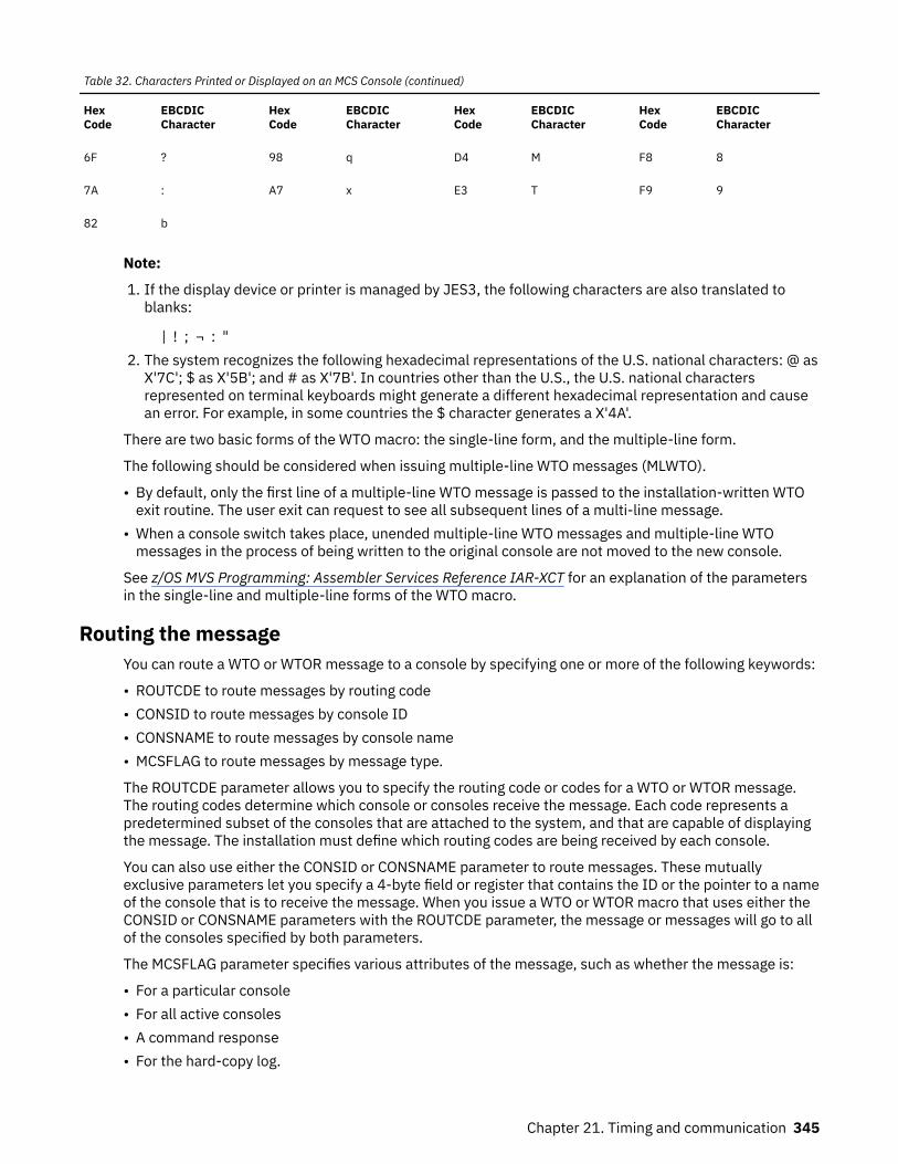
Table 32. Characters Printed or Displayed on an MCS Console (continued)
HexCode
EBCDICCharacter
HexCode
EBCDICCharacter
HexCode
EBCDICCharacter
HexCode
EBCDICCharacter
6F ? 98 q D4 M F8 8
7A : A7 x E3 T F9 9
82 b
Note:
1. If the display device or printer is managed by JES3, the following characters are also translated toblanks:
| ! ; ¬ : "2. The system recognizes the following hexadecimal representations of the U.S. national characters: @ as
X'7C'; $ as X'5B'; and # as X'7B'. In countries other than the U.S., the U.S. national charactersrepresented on terminal keyboards might generate a different hexadecimal representation and causean error. For example, in some countries the $ character generates a X'4A'.
There are two basic forms of the WTO macro: the single-line form, and the multiple-line form.
The following should be considered when issuing multiple-line WTO messages (MLWTO).
• By default, only the first line of a multiple-line WTO message is passed to the installation-written WTOexit routine. The user exit can request to see all subsequent lines of a multi-line message.
• When a console switch takes place, unended multiple-line WTO messages and multiple-line WTOmessages in the process of being written to the original console are not moved to the new console.
See z/OS MVS Programming: Assembler Services Reference IAR-XCT for an explanation of the parametersin the single-line and multiple-line forms of the WTO macro.
Routing the messageYou can route a WTO or WTOR message to a console by specifying one or more of the following keywords:
• ROUTCDE to route messages by routing code• CONSID to route messages by console ID• CONSNAME to route messages by console name• MCSFLAG to route messages by message type.
The ROUTCDE parameter allows you to specify the routing code or codes for a WTO or WTOR message.The routing codes determine which console or consoles receive the message. Each code represents apredetermined subset of the consoles that are attached to the system, and that are capable of displayingthe message. The installation must define which routing codes are being received by each console.
You can also use either the CONSID or CONSNAME parameter to route messages. These mutuallyexclusive parameters let you specify a 4-byte field or register that contains the ID or the pointer to a nameof the console that is to receive the message. When you issue a WTO or WTOR macro that uses either theCONSID or CONSNAME parameters with the ROUTCDE parameter, the message or messages will go to allof the consoles specified by both parameters.
The MCSFLAG parameter specifies various attributes of the message, such as whether the message is:
• For a particular console• For all active consoles• A command response• For the hard-copy log.
Chapter 21. Timing and communication 345

Control is returned to the issuer with a return code of X‘20’ and a reason code in register 0. The reasoncode is equal to the number of active WTO buffers for the issuer's address space. WTO processing mayplace the WTP invocation in a wait state until WTO buffers are again available.
Note: For the convenience of the operator, you can associate messages with individual keynames. Akeyname consists of 1 to 8 alphanumeric characters, and it appears with the message on the console. Thekeyname can be used as an operand in the DISPLAY R console command, which operators can issue atthe console. Use the KEY parameter on the WTO or WTOR macro for this purpose.
During system initialization, each operator's console in the system is assigned routing codes thatcorrespond to the functions that the installation wants that console to perform. When any of the routingcodes assigned to a message match any of the routing codes assigned to a console, the message is sentto that console.
Disposition of the message is indicated through the descriptor codes specified in the WTO macro.Descriptor codes classify WTO messages so that they can be properly presented on, and deleted from,display devices. The descriptor code is not printed or displayed as part of the message text.
If the user supplies a descriptor code in the WTO macro, an indicator is inserted at the start of themessage. The indicators are: a blank, an at sign (@), an asterisk (*), or a blank followed by a plus sign (+).The indicator inserted in the message depends on the descriptor code that the user supplies and whetherthe user is a privileged or APF-authorized program or a non-authorized problem program. Table 33 onpage 346 shows the indicator that is used for each descriptor code.
Table 33. Descriptor Code Indicators
Descriptor Code Non-AuthorizedProblem Program
1 @
2 @
3-10 blank+
11 @
12-13 blank+
A critical eventual action is an action that the operator must perform, as soon as possible, in response to acritical situation during the operation of the system. For example, if the dump data set is full, the operatoris notified to mount a new tape on a specific unit. This is considered a critical action because no dumpscan be taken until the tape is mounted; it is eventual rather than immediate because the systemcontinues to run and processes jobs that do not require dumps.
Action messages to the operator, which are identified by the @ or * indicator, can be individuallysuppressed by the installation. When a program invokes WTO or WTOR to send a message, the systemdetermines if the message is to be suppressed. If the message is to be suppressed, the system writes themessage to the hardcopy log and the operator does not receive it on the screen. For more information onsuppressing messages, see z/OS MVS Planning: Operations.
If a program issues a message with descriptor code of 1 or 2, the message is deleted at address space ortask termination. For more information concerning routing and descriptor codes, see any of the volumesof MVS System Messages.
If an application that uses WTO needs to alter a message each time the message is issued, the list form ofthe WTO macro may be useful. You can alter the message area, which is referenced by the WTOparameter list, before you issue the WTO. The message length, which appears in the WTO parameter list,does not need to be altered if you pad out the message area with blanks.
A sample WTO macro is shown in Figure 97 on page 347.
346 z/OS: z/OS MVS Assembler Services Guide

Single-line WTO 'BREAKOFF POINT REACHED. TRACKING COMPLETED.',format ROUTCDE=14,DESC=7 Multiple- WTO ('SUBROUTINES CALLED',C),line format ('ROUTINE TIMES CALLED',L),('SUBQUER',D),(list form) ('ENQUER',D),('WRITER',D), ('DQUER',DE), ROUTCDE=(2,14),DESC=(7,8,9),MF=L
Figure 97. Writing to the Operator
Altering message textIf an application that uses WTO needs to alter the same message or numerous messages repetitively,using the TEXT parameter on the WTO macro may be useful. You can alter the message or messages inone of two ways:
• If you issue 3 different messages, all with identical parameters other than TEXT, you can create a listform of the macro, move the text into the list form, then execute the macro. Using the TEXT parameteryou can use the standard form of the macro, and specify the address of the message text. By reducingthe number of list and execute forms of the WTO macro in your code, you reduce the storagerequirements for your program.
• If you need to modify a parameter in message text, using the TEXT parameter enables you to modify theparameter in the storage that you define in your program to contain the message text, rather thanmodify the WTO parameter list.
Using the TEXT parameter on WTO can reduce your program's storage requirements because of fewerlines of code or fewer list forms of the WTO macro.
To use the WTOR macro, code the message exactly as designated in the single-line WTO macro. (TheWTOR macro cannot be used to pass multiple-line messages.) When the message is written, the systemadds a message identifier before the message to associate the reply with the message. The system alsoinserts an indicator as the first character of all WTOR messages, thereby informing the operator thatimmediate action is required. You must, however, indicate the response desired. In addition, you mustsupply the address of the area in which the system is to place the reply, and you must indicate themaximum length of the expected reply. The length of the reply may not be zero. You also supply theaddress of an event control block which the system posts after the reply has been placed, left-adjusted, inyour designated area.
You can also supply a command and response token, or CART, with any message. You may have receiveda CART as input in cases where you issued a message in response to a command. In these cases, youshould specify this CART on any messages you issue. Using the CART guarantees that these messages areassociated with the command.
A sample WTOR macro is shown in Figure 98 on page 347. The reply is not necessarily available at theaddress you specified until the specified ECB has been posted.
. . XC ECBAD,ECBAD Clear ECB WTOR 'STANDARD OPERATING CONDITIONS? REPLY YES OR NO', REPLY,3,ECBAD,ROUTCDE=(1,15) WAIT ECB=ECBAD . .ECBAD DC F'0' Event control blockREPLY DC C'bbb' Answer area
Figure 98. Writing to the Operator With a Reply
When a WTOR macro is issued, any console receiving the message has the authority to reply. The firstreply received by the system is returned to the issuer of the WTOR, providing the syntax of the reply is
Chapter 21. Timing and communication 347

correct. If the syntax of the reply is not correct, another reply is accepted. The WTOR is satisfied when thesystem moves the reply into the issuer's reply area and posts the event control block. Each console thatreceived the original WTOR also receives the accepted reply unless it is a security message. A securitymessage is a WTO or WTOR message with routing code 9. No console receives the accepted reply to asecurity message. A console with master authority may answer any WTOR, even if it did not receive theoriginal message.
Writing a multiple-line messageTo write a multiple-line message to one or more operator consoles, issue WTO or WTOR with all lines oftext.
Embedding label lines in a multiple-line messageLabel lines provide column headings in tabular displays. You can change the column headings used todescribe different sections of a tabular display by embedding label lines in the existing multiple-line WTOmessage for a tabular display.
Note: You cannot use the WTO macro to embed label lines. The WTO macro handles label lines at thebeginning of the message only.
Communicating in a sysplex environmentThe WTO macro allows applications to send messages to consoles within a sysplex, without having to beaware that more than one system is up and running.
You can direct a WTO message to a specific console by specifying the console ID or name when issuingthe message. For example, you can use the CONSID or CONSNAME parameter on the WTO macro to directthe WTO message to consoles defined by those parameters. If the console is not active anywhere withinthe sysplex, the system writes the message to the system log unless it is an important informationmessage, an action message or WTOR message. An important information message is a WTO or WTORmessage with descriptor codes 1, 2, 3, 11, or 12. Action messages, messages with descriptor code 12,and WTORs are written to the system log.
You can also broadcast WTOs to all active consoles using MCSFLAG=BRDCST on the WTO macro.Unsolicited messages are directed by routing code, message level, and message type to the appropriateconsoles anywhere within the sysplex. There may be some unsolicited messages that will not be queuedto any console at a receiving system. In this case, all of the messages are written to the system log.
Writing to the programmerThe WTO and the WTOR macros allow you to write messages to a programmer who is logged onto a TSO/Eterminal, as well as to the operator. However, only the operator can reply to a WTOR message.
To write a message to the programmer, you must specify ROUTCDE=11 in the WTO or the WTOR macro.
Writing to the system logThe system log consists of one SYSOUT data set on which the communication between the operator andthe system is recorded. You can send a message to the system log by coding the information that you wishto log in the "text" parameter of the WTL macro.
The WTO macro with the MCSFLAG=HRDCPY parameter also writes messages to the system log. BecauseWTO allows you to supply more information on the macro invocation than WTL, IBM recommends thatyou use WTO instead of WTL.
The system writes the text of your WTL macro on the master console instead of on the system log if thesystem log is not active.
348 z/OS: z/OS MVS Assembler Services Guide

Although when using the WTL macro you code the message within apostrophes, the written messagedoes not contain the apostrophes. The message can include any character that is valid for the WTO macroand is assembled and written the same way as the WTO macro.
Note: The exact format of the output of the WTL macro varies depending on the job entry system (JES2 orJES3) that is being used, the output class that is assigned to the log at system initialization, and whetherDLOG is in effect for JES3. If JES3 DLOG is being used, system log entries are preceded by a prefix thatincludes a time stamp and routing information. If the combined prefix and message exceeds 126characters, the log entry is split at the first blank or comma encountered when scanning backward fromthe 126th character of the combined prefix and message. See z/OS JES3 Commands for information aboutthe DLOG format of the log entry when using JES3.
Deleting messages already writtenThe DOM macro deletes the messages that were created using the WTO or WTOR macros. Depending onthe timing of a DOM macro relative to the WTO or WTOR, the message may or may not have alreadyappeared on the operator's console.
• When a message already exists on the operator screen, it has a format that indicates to the operatorwhether the message still requires that some action be taken. When the operator responds to amessage, the message format changes to remind the operator that a response was already given. WhenDOM deletes a message, it does not actually erase the message. It only changes its format, displaying itlike a non-action message.
• If the message is not yet on the screen, DOM deletes the message before it appears. The DOMprocessing does not affect the logging action. That is, if the message is supposed to be logged, it will be,regardless of when or if a DOM is issued. The message is logged in the format of a message that iswaiting for operator action.
The program that generates an action message is responsible for deleting that message. To delete amessage, identify the message by using the MSG, MSGLIST, or TOKEN parameters on the DOM macro, andissue DOM.
When you issued WTO or WTOR to write the message, the system returned a message ID in generalpurpose register 1. Use this ID as input on the MSG or MSGLIST parameters on the DOM macro. MSGLIST(message list) associates several message IDs with the delete request. The number of message IDs in themessage list is defined by the COUNT parameter or it is defined by a 1 in the high-order bit position of thelast message ID in the list. The COUNT parameter cannot exceed 60. If you specified the TOKENparameter on WTO to generate your own message ID, use the same value on the TOKEN parameter onDOM to delete that message.
Retrieving console information (CONVCON and CnzConv macros)Programs that either process commands or issue messages might need information about MCS, SMCS orextended MCS consoles. CONVCON and CnzConv obtain information about these consoles.
IBM recommends using the CnzConv macro to retrieve console information. The CONVCON service will nolonger be enhanced. Future enhancement will be provided only on the CnzConv service.
You can use both the CnzConv and CONVCON macros to do the following tasks:
• Obtain the console name associated with an input console ID.• Obtain the console ID associated with an input console name.• Obtain the status of a console (active or inactive) of an input console ID or name.• Obtain the system name on which the queried console is active.
In addition to these tasks, you can use the CnzConv macro to obtain the following information, with aninput console ID or name:
• The console type (MCS, SMCS, EMCS, Subsystem, or Special).• The console subtype (Internal, Instream, or Unknown. Applies to a console type of special only).
Chapter 21. Timing and communication 349

• The logical unit of an SMCS console.• The owner name of a subsystem console.• The ASID of a Subsystem console.
You must set up a parameter list before invoking the macros. Depending upon the information you want,you must initialize certain fields in the parameter list, and the macros return information in other fields ofthe parameter list. For more information on the CONVCON parameter list, which is mapped by IEZVG200,see z/OS MVS Data Areas in the z/OS Internet library (www.ibm.com/servers/resourcelink/svc00100.nsf/pages/zosInternetLibrary).
The following topics describe possible uses for the CnzConv and CONVCON macroS, and tell you how tofill in the parameter list for each use. The parameter list values for both macros are discussed in z/OS MVSProgramming: Assembler Services Reference ABE-HSP.
Using console names instead of console IDsInstallation operators and programmers previously referred to MVS consoles only by console IDs. IBMnow requires that you use names when referring to MCS consoles. Using names can help operators andprogrammers:
• Remember which console they want to reference in commands or programs. For example, if yourinstallation establishes one console to receive information about tapes, and uses the console nameTAPE, operators and programmers can more easily remember TAPE than a console ID such as 03.
• Connect information in messages and the hardcopy log to the correct console. If your installation usesconsole IDs, operators and programmers might have difficulty identifying the console to whichmessages and hardcopy log information applies, because the system uses console names in messagesand the hardcopy log.
Using console names rather than IDs can also avoid confusion when a console ID might change. If yourinstallation has set up a sysplex environment, and uses console IDs to identify consoles, those IDs canchange from one IPL to the next, or when systems are added or removed from the sysplex. A console ID isnot guaranteed to be associated with one console for the life of a sysplex.
Determining the name or ID of a consoleYou can use both CnzConv and CONVCON macros to determine the name or ID of a console.
Using CnzConv: To obtain the console ID for an input console name, do the following steps:
1. Clear the CnzConv parameter list by setting it to zeros.2. Specify the following parameters:
• CnzConv InConsoleName=MyConsoleName• OutConsoleId=OutConsoleId• Rtncode=CnzConvReturnCode• Rsncode=CnzConvReasonCode
3. Issue the CnzConv macro.
When CnzConvReturnCode is equal to CnzConvRc0_Ok, OutConsoleId contains the output console id.
To obtain the console name for an input console ID, do the following steps:
1. Clear the CnzConv parameter list by setting it to zeros.2. Specify the following parameters:
• CnzConv InConsoleId=MyConsoleId• OutConsoleName=OutConsoleName• Rtncode=CnzConvReturnCode• Rsncode=CnzConvReasonCode
350 z/OS: z/OS MVS Assembler Services Guide

3. Issue the CnzConv macro.
When CnzConvReturnCode is equal to CnzConvRc0_Ok, OutConsoleName contains the output consolename.
Using CONVCON: To obtain the console ID for an input console name, do the following steps:
1. Clear the CONVCON parameter list by setting it to zeros.2. Initialize the following fields in the parameter list:
• The version ID (CONVVRSN)• The acronym (CONVACRO)• The console ID (CONVID)• The flag indicating that you are supplying the console ID (flag CONVPID in CONVFLGS)
3. Issue the CONVCON macro.
When CONVCON completes, the console name is in the parameter list field CONVNAME, and register 15contains a return code.
To obtain the console name for an input console ID, do the following steps:
1. Clear the CONVCON parameter list by setting it to zeros.2. Initialize the following fields in the parameter list:
• The version ID (CONVVRSN)• The acronym (CONVACRO)• The console name (CONVFLD)• The flag bit indicating that you are supplying the console name (flag CONVPFLD in CONVFLGS)
If the console name in CONVFLD is less than 10 characters, pad the name with blanks.
The installation defines console names at initialization time in the CONSOLxx member of parmlib. Youcan use the DISPLAY CONSOLES command to receive a list of defined names.
3. Issue the CONVCON macro.
When CONVCON completes, the console ID will be in the parameter field CONVID.
Validating a console name or ID and obtaining the active system nameBefore issuing a message to a specific console, you might want to validate if it has been defined. An activeconsole is one that is defined and running. An application can use the CnzConv or CONVCON macro toobtain the console status (active or inactive) and the active system name, with an input console name orID.
Using CnzConv: To obtain the console status and active system name of an input console name or ID, dothe following steps:
1. Clear the CnzConv parameter list by setting it to zeros.2. Specify the following parameters:
• CnzConv InConsoleName=MyConsoleName or CnzConv InConsoleId=MyConsoleId, depending onwhat information you currently have
• ConsoleStatus=OutConsoleStatus• SysName=OutSysName• Rtncode=CnzConvReturnCode• Rsncode=CnzConvReasonCode
3. Issue the CONVCON macro.
Chapter 21. Timing and communication 351

When CnzConvReturnCode is equal to CnzConvRc0_Ok, the input console name or id is defined. IfOutConsoleStatus is equal to CnzConv_kStatus_Active, OutSysName contains the system on which theconsole is active.
Using CONVCON: To obtain the console status and active system name of an input console name or ID, dothe following steps:
1. Clear the CONVCON parameter list by setting it to zeros.2. Initialize the following fields in the parameter list:
• The version ID (CONVVRSN)• The acronym (CONVACRO)• Either the console name (CONVFLD) or the console ID (CONVID) depending on what information you
currently have. The installation defines console names at initialization time in the CONSOLxxmember of Parmlib. You can use the DISPLAY CONSOLES command to receive a list of definednames.
• The appropriate flag in CONVFLGS indicating whether you are specifying the console name(CONVPFLD) or the ID (CONVPID) as input.
3. Issue the CONVCON macro.
When CONVCON completes, CONVSYSN contains the name of the system to which the console isattached, if the console you specified is active. Register 15 contains a return code. If you receive thefollowing return codes, check the reason code in CONVRSN for an explanation.
• Return code 0 indicates that the console name or ID is valid and the console is active.• Return code 4 indicates that the name or ID is valid, but the console is not active.• Return code 8 indicates that the console name is incorrect.• Return code 0C indicates that the console ID is incorrect.
See z/OS MVS Programming: Assembler Services Reference ABE-HSP for an explanation of all return codes.
352 z/OS: z/OS MVS Assembler Services Guide

Chapter 22. Translating messages
The MVS message service (MMS) provides a method of translating message text, and provides aconvenient method of storing message text.
• MMS enables you to translate U.S. English messages into other languages. These messages can be IBM-supplied messages or application messages. An application can format message text for any language,including English, by issuing the TRANMSG macro.
• MMS enables you to store message text in MMS message files rather than in the application code. Byusing MMS to store message text, you eliminate the need to include the message text as part of theapplication code. Any program that needs to issue a particular message can get it from one place: a run-time message file. A run-time message file contains messages in a format that MMS can use. You canalso update your messages in the install message files rather than in the source code. An installmessage file is a partitioned data set (PDS) that contains message skeletons. A message skeletoncontains message text and substitution data.
Applications running on TSO/E can have their messages translated automatically if the primary languageassociated with the TSO/E session is the same language as the language of the run-time message file. Aprimary language is one that is defined in your TSO/E profile. Therefore, even if you are issuing messagesby using the WTO macro, you can present a message in the primary language associated with the TSO/Esession. If you are routing system messages to a TSO/E extended MCS console, and MMS is active, usersof extended MCS consoles on TSO/E can select available languages for message translation and thesystem will display translated messages on the user's screen.
Applications based on products not already using MMS must translate their own messages by invoking theTRANMSG macro.
MMS can handle multi-line and multiple format messages. Multi-line messages are messages displayedover a number of lines on an output device. Multiple format messages are messages that have the samemessage ID, but have differing text content depending on the circumstances under which they are issued.
Preparing IBM-supplied messages for translation: To prepare IBM messages for translation, perform thefollowing tasks:
1. Ensure that the appropriate IBM-supplied system install message files have been installed on yoursystem.
For MVS messages (MVS, JES2, TSO/E), IBM provides an install message file for U.S. Englishmessages. IBM will also supply Japanese versions of those messages, if requested. When you installMVS, these messages are automatically put into install message files. The U.S. English file is calledSYS1.MSGENU.
2. Create a system run-time message file for each language by running the system's install message filesthrough the message compiler. See “Compiling message files” on page 359 for details on using thecompiler.
Preparing application messages for translation: To prepare an application's messages for translation,perform the following tasks.
1. Create a PDS for the English version, and a PDS for the translated version of the application'smessages. To make it easy to locate and update messages, group messages for each program,component, or other category into separate PDS members. These data sets are the application's installmessage files. The logical record length of the data set should be variable length of 259, and the blocksize 23476. IBM recommends that you put IBM messages first in a PDS concatenation. If you are nottranslating IBM messages, you can still use the same recommended logical record length and blocksize.
2. Validate the application's install message files by running each PDS through the message compiler.See “Compiling message files” on page 359 for details on using the compiler. The MMS message
© Copyright IBM Corp. 1988, 2020 353

compiler replaces the entire run-time message file, so create a test run-time message file for eachlanguage, using names different from those containing IBM-supplied messages. Creating a test run-time message file enables you to verify the new messages without disturbing the existing system run-time message files and current message translation.
3. After a clean compile, add your PDS members into the system's install message files as new members.4. Update the system run-time message files by running the system's install message files through the
message compiler. See “Updating the system run-time message files” on page 362 for details onupdating the system run-time message files.
Figure 99 on page 354 illustrates the process of preparing messages for translation.
Figure 99. Preparing Messages for Translation
Translating application messages using the MVS message service: To use MMS in an application, modifythe application to exploit the translation service that MMS provides:
• Use the QRYLANG macro to determine which languages are currently available at your installation. Formore information on QRYLANG, see “Determining which languages are available (QRYLANG macro)” onpage 362.
• Use the TRANMSG macro to obtain from MMS the translated version or the complete U.S. Englishmessage text of an application's message or messages. For more information on TRANMSG, see“Retrieving translated messages (TRANMSG macro)” on page 363.
The installation can translate messages into more than one language. See “Support for additionallanguages” on page 366.
354 z/OS: z/OS MVS Assembler Services Guide

Allocating data sets for an applicationFor an application whose messages will be translated, you must allocate a PDS for each language in whichthe messages might appear. For example, if you want the messages to be available in both English andJapanese, you must allocate two data sets: one to contain the English message skeletons, and one tocontain the Japanese.
See z/OS MVS JCL User's Guide and z/OS MVS JCL Reference for information about allocating data sets.
Creating install message filesEach install message file must contain a version record and one or more message skeletons, and maycontain any number of comment records throughout. The message compiler treats any record with thecharacters ".*" in columns 1 and 2 as a comment line and ignores it.
Creating a version recordThe version record must be the first non-comment record in each install message file, and have theformat shown in Table 34 on page 355. If you are translating MVS messages, you can use the contents ofthe version record fields for informational purposes. If you are creating messages for an applicationprogram, you need only to supply input to columns 1 through 6. Columns 7 through 38 can be blanks.
Table 34. Format of Version Record Fields
Columns Contents and Description
1 & 2 ".V" Identifies this record as a version record.
3-5 Three-character language code of the messages.
6 Character field containing a Y or N, indicating whether this language contains a double-bytecharacter set (DBCS).
7-14 Field maintenance identifier (FMID) applicable to the messages within the member, padded onthe right with blanks.
15-22 Product identifier applicable to the messages within the member, padded on the right withblanks.
23-38 Service level applicable to the member, padded on the right with blanks.
The following is an example of a version record.
.VENUNJBB44N1 5695-047005
Table 35 on page 355 explains the previous example of the version record.
Table 35. Version Record Example
Columns Example Description
1 & 2 .V Version record
3-5 ENU Three-character language code
6 N DBCS indicator
7-14 JBB44N1␢ FMID
15-22 5695-047 Product identifier
23-38 005 Service level information
Creating message skeletonsThe rest of each install message file consists of message skeletons.
Chapter 22. Translating messages 355

Each message requires one or more message skeletons. A message skeleton consists of a message keyand message text, which can include substitution tokens. A message key consists of a message identifier,format number, and line number.
Note: If the message skeleton you are creating contains a TIME, DATE, or DAY substitution token, theformat must be defined in the system configuration member, CNLcccxx, for the language. See z/OS MVSInitialization and Tuning Reference for more information on these substitution tokens.
Message skeleton formatEach message skeleton must follow the column format shown in Table 36 on page 356.
Table 36. Message Skeleton Fields
Columns Contents and Description
1-10 Message identifier (msgid). A message identifier can be 1 to 10 characters long, padded with EBCDIC blanks, ifnecessary, so that it totals ten characters. The first character must be alphabetic. A message identifier cannotcontain double-byte characters and cannot contain embedded blanks.
Ensure that the message identifiers for your application program messages do not conflict with existing MVSmessage identifiers. To avoid conflict, do not begin a message identifier with the letters A through I.
Examples of message identifiers are:
• IKJ52301I• IEF12345W• HASP000• IEF123I• OLDMSGID
Note that MMS will remove the first character of any message identifier in the form xmsgid before processing, andwill replace it after processing. "x" is any character that is not uppercase alphabetic, such as $ or 1.
11 & 12 Line number (ll). If the message is a single-line message, leave columns 11 and 12 blank. For a multi-line message,assign line numbers sequentially within the message. Line numbers do not have to be contiguous. Valid numbersare 01 to 99.
Ensure that message line numbers for a translated skeleton match the line numbers of the corresponding U.S.English message skeleton.
Note: Ensure that corresponding skeletons (same message identifier and line number) of multi-line messagescontain the same substitution tokens. For example, if substitution tokens &1. and &2=date. are on line 01 of a two-line U.S. English message skeleton, these tokens must appear on line 01 of a translated skeleton. The following isan example of a multi-line message skeleton:
MSGID01 01 THIS IS LINE ONE OF THIS MULTI-LINE MESSAGEMSGID01 02 THIS IS LINE TWO OF THIS MULTI-LINE MESSAGEMSGID01 03 THIS IS LINE THREE OF THIS MULTI-LINE MESSAGE
13-15 Format number (fff). If only one format is defined for a particular message identifier, leave columns 13-15 blank.
Use format numbers to maintain compatibility with existing messages. Using format numbers for new messages isnot recommended.
Format numbers distinguish among message skeletons that have one message identifier but have several differenttext strings or substitution tokens. The message identifier alone cannot identify the message as unique in thesecases. The format number, together with the message identifier, identifies the message.
If more than one format is defined for a particular message identifier, assign a unique format number to eachskeleton for that message identifier. Valid numbers are 001 to 999. You do not have to assign the numberssequentially. Ensure that the format number in the translated skeleton matches the format number in the U.S.English message skeleton.
Each message ID might have several format numbers if that message has variable text.
16 Blank (␢). Column 16 must contain an EBCDIC blank.
356 z/OS: z/OS MVS Assembler Services Guide

Table 36. Message Skeleton Fields (continued)
Columns Contents and Description
17 & 18 Translated line number (mm).
If one line of a U.S. English message translates into more than one line of text in another language, you mustprovide additional lines for the translated version. Create one or more skeletons in the other language and assign atranslated line number to each translated line. Valid translated line numbers are 01 to 99.
Example:
IEFP0001 MAXIMUM PASSWORD ATTEMPTS BY SPECIAL USER &1. AT TERMINAL &2.
IEFP0001 01 LE USER SPECIALE &1. A TERMINAL &2. 02 ONT ENTRER PASSWORD TROP DE TEMPS
You can also use translated line numbers for English message skeletons if your input to the TRANMSG macro is anMPB (message parameter block). In this case, TRANMSG will return all message lines in English for a givenmessage ID.
If a line of a U.S. English message translates to only one line, leave the translated line number blank.
19 EBCDIC blank indicates no extended function.
One (1) indicates that this skeleton line is the start of a multi-line message and the next line contains a message IDthat is to be used to locate the correct message skeleton.
20 + Message text. See “Message text in a skeleton” on page 357
The following are examples of message skeletons.
msgid llfff␢mm text
HASP001 ACCESS TO DATASET &DSN DENIED
IACT0012W 001 DATASET &DSN1 NOT FOUNDIACT0012W 002 COULD NOT FIND DATASET &FILE
HASP999I 01 ACCESS TO DATASET &X-1 DENIED:HASP999I 02 USER INFORMED AT &2;=DATE02. ON TERMINAL &X-3HASP999I 03 LEADING BLANKS ARE OK
IEFA003F 001 USER &USERID VIOLATED ACCESS RIGHTS TO DATASET &X-2 AT &3;=TIME.IEFA003F 002 &1;=TIME.: USER &X-2 VIOLATED ACCESS RIGHTS TO DATASET &X-3
Message text in a skeletonMessage text in a message skeleton must conform to certain format standards. The standards are asfollows:
• Message text can be up to 255 bytes long including the message identifier, line number, and otherfields.
• Message text can be upper-, lower-, or mixed case.• Message text can be all single-byte character set (SBCS), all double-byte character set (DBCS), or a
combination of both. Blanks are valid characters, and are acceptable as any part of the message text.Message text can contain substitution tokens.
A substitution token is a "place marker," identifying substitution data to MMS. MMS does not translatesubstitution tokens in the target language skeleton, but rather replaces them with actual substitutiondata.
Both &DSN1 and &FILE in the following examples are substitution tokens.
IACT0012W 001 DATASET &DSN1. NOT FOUNDIACT0012W 002 COULD NOT FIND DATASET &FILE;
Chapter 22. Translating messages 357

Substitution tokens indicate substitution, or variable, data, such as a data set name or a date in themessage text. Substitution tokens must start with a token start trigger character, an ampersand (&), andend with a token end trigger character, a period (.). These characters are part of the token and are notincluded in the message text display. You may include an ampersand (&) in the text as long as it does nothave a period following it in the format of a substitution token. Substitution tokens must be SBCScharacters and follow the form &name[=format] where:name
is the name of the substitution token. This name is an alphanumeric SBCS string. The name must notcontain imbedded blanks or DBCS characters.
formatis an optional format descriptor for the substitution token. Format descriptors are:
• TEXT for tokens other than dates and times (default format)• DATExxxxxx for dates• TIMExxxxxx for times• DAY for the day of the week
If you use these format descriptors, you must also define them in the CNLcccxx parmlib member forthe language. See z/OS MVS Initialization and Tuning Reference for more information on formatdescriptors.
The total length of name and =format must not be greater than 16 bytes.
If you do not include a format descriptor for a particular substitution token, the MVS message servicetreats the token as TEXT.
The date and time tokens are formatted according to the language. There are no defaults. You mustsupply your own formats in the CNLcccxx member.
Examples of substitution tokens are:
&1.&USERID.&1=DATE1.&5=TIMESHORT.
Validating message skeletonsAfter creating message skeletons for both the U.S. English and translated version of each message,validate the skeletons. To validate the skeletons, run each of the application's install message filesthrough the message compiler for syntax checking. Otherwise you might be adding incorrect skeletons tothe files that MMS uses, and your messages might be either incorrectly translated or untranslatable. Youshould also validate skeletons when you add or change skeletons in an existing install message file.
To make sure your message skeletons are valid, complete the following process for each install messagefile:
1. Allocate storage for run-time message files, which the compiler produces as output.2. Compile the install message file by invoking the compiler.3. Check the return code from the message compiler.
If the return code does not indicate a clean compile, use the compiler error messages to correct anyerrors in the skeletons. The compiler writes its error messages to the SYSPRINT data set. Then compilethe install message file again.
The return code and error messages from the compiler are the only output you need to determinewhether the message skeletons are correct. However, compiling an application's install message file alsoproduces formatted run-time message files. Before invoking the compiler, you must allocate storage forthese run-time files, but you cannot use them as input for MMS. To make your application's messagesavailable for translation, you must add your PDS to the system's install message files, and run those filesthrough the compiler again.
358 z/OS: z/OS MVS Assembler Services Guide

Allocating storage for validation run-time message filesThe data set you create for the run-time message files must be a linear VSAM data set that can be used asa data-in-virtual object. You must create one run-time file for each install message file for yourapplication.
The amount of storage you will need to allocate for a validation run-time message file cannot bedetermined exactly. The amount of storage depends on the number of skeletons, the size of the skeletons,the number of substitution tokens within the skeletons, and the types of messages represented by theskeletons (single-line, multi-line, or multi-format). IBM recommends that, for a validation run-timemessage file, you allocate twice the amount of storage required for the install message file you arecompiling. In most cases, this storage should be adequate.
To create the data set for the run-time message files, you need to specify the DEFINE CLUSTER functionof access method services (IDCAMS) with the LINEAR parameter. When you code the SHAREOPTIONSparameter for DEFINE CLUSTER, use SHAREOPTIONS (1,3). For a complete explanation ofSHAREOPTIONS, see z/OS DFSMS Using Data Sets.
The following is a sample job that invokes IDCAMS to create the linear data set named SYS1.ENURMF onthe volume called MMSPK1. When IDCAMS creates the data set, it is empty. Note that there is noRECORDS parameter; linear data sets do not have records.
//DEFCLUS JOB MSGLEVEL=(2,0),USER=IBMUSER//*//* DEFINE DIV CLUSTER//*//DCLUST EXEC PGM=IDCAMS,REGION=4096K//SYSPRINT DD SYSOUT=*//MMSPK1 DD UNIT=3380,VOL=SER=MMSPK1,DISP=OLD//SYSIN DD * DELETE (SYS1.ENURMF) CL PURGE DEFINE CLUSTER (NAME(SYS1.ENURMF) - VOLUMES(MMSPK1) - CYL(1 1) - SHAREOPTIONS(1,3) - LINEAR) - DATA (NAME(SYS1.ENURMF.DATA))/*
Figure 100. Sample job to invoke IDCAMS to obtain a data set for the run-time message files
Compiling message filesThe message compiler creates run-time message files from an install message file. You need to run themessage compiler once for each language you install and each time you update the application's installmessage files. The compiler expects a PDS or a concatenation of PDSs as input. If the compiler cannotprocess a message skeleton, it issues an error message. It also sets a return code. See “Checking themessage compiler return codes” on page 362 for a description of compiler return codes.
Invoking the message compilerThe message compiler is an executable program. You can use JCL, a TSO/E CLIST, or a REXX EXEC toinvoke the message compiler. The syntax for each type of invocation follows. The meaning of the variables(shown in lowercase in the examples) follows the examples.
//COMPILE EXEC PGM=CNLCCPLR, // PARM=(lang,dbcs) //SYSUT1 DD DSN=msg_pds,DISP=SHR //SYSUT2 DD DSN=msg_div_obj,DISP=(OLD,KEEP,KEEP) //SYSPRINT DD SYSOUT=*
Figure 101. Using JCL to Invoke the Compiler with a single PDS as input
Chapter 22. Translating messages 359

//COMPILE EXEC PGM=CNLCCPLR, // PARM=(lang,dbcs) //SYSUT1 DD DSN=msg_pds1,DISP=SHR // DD DSN=msg_pds2,DISP=SHR : : // DD DSN=msg_pdsn,DISP=SHR //SYSUT2 DD DSN=msg_div_obj,DISP=(OLD,KEEP,KEEP) //SYSPRINT DD SYSOUT=*
Figure 102. Using JCL to Invoke the Compiler with a concatenation of partitioned Data Sets as input
PROC 0 FREE DD(SYSUT1,SYSUT2,SYSPRINT) /* FREE DD'S */ ALLOC DD(SYSUT1) DSN('msg_pds') SHR /* ALLOC INPUT FILE */ ALLOC DD(SYSUT2) DSN('msg_div_obj') OLD /* ALLOC OUTPUT FILE */ ALLOC DD(SYSPRINT) DSN(*) /* ALLOC SYSPRINT */ CALL 'SYS1.LINKLIB(CNLCCPLR)' 'lang,dbcs' /* CALL MESSAGE COMPILER */ SET &RCODE = &LASTCC /* SET RETURN CODE */ FREE DD(SYSUT1,SYSUT2,SYSPRINT) /* FREE FILES */ EXIT CODE(&RCODE) /* EXIT */
Figure 103. Using a TSO/E CLIST to Invoke the Compiler with a single PDS input
PROC 0 FREE DD(SYSUT1,SYSUT2,SYSPRINT) /* FREE DD'S */ ALLOC DD(SYSUT1) DSN('msg_pds1' + /* ALLOC INPUT FILE */ ALLOC DD(SYSUT1) DSN 'msg_pds1' + /* ALLOC INPUT FILE */ : : ALLOC DD(SYSUT1) DSN 'msg_pdsn') SHR /* ALLOC INPUT FILE */ ALLOC DD(SYSUT2) DSN('msg_div_obj') OLD /* ALLOC OUTPUT FILE */ ALLOC DD(SYSPRINT) DSN(*) /* ALLOC SYSPRINT */ CALL 'SYS1.LINKLIB(CNLCCPLR)' 'lang,dbcs' /* CALL MESSAGE COMPILER */ SET &RCODE = &LASTCC /* SET RETURN CODE */ FREE DD(SYSUT1,SYSUT2,SYSPRINT) /* FREE FILES */ EXIT CODE(&RCODE) /* EXIT */
Figure 104. Using a TSO/E CLIST to Invoke the Compiler with a concatenation of partitioned Data Set asinput
/* MESSAGE COMPILER INVOCATION EXEC */
MSGCMPLR:
"FREE DD(SYSUT1,SYSUT2,SYSPRINT)"
"ALLOC DD(SYSUT1) DSN('"msg_pds"') SHR""ALLOC DD(SYSUT2) DSN('"msg_div_obj"') OLD""ALLOC DD(SYSPRINT) DSN(*)"
"CALL 'SYS1.LINKLIB(CNLCCPLR)' 'lang,dbcs'"
compiler_rc=rc
"FREE DD(SYSUT1,SYSUT2,SYSPRINT)"
return(compiler_rc)
Figure 105. Using a REXX exec to Invoke the Compiler with a single PDS as input
360 z/OS: z/OS MVS Assembler Services Guide

/* MESSAGE COMPILER INVOCATION EXEC */
MSGCMPLR:
"FREE DD(SYSUT1,SYSUT2,SYSPRINT)"
"ALLOC DD(SYSUT1) DSN('msg_pds1',", "'msg_pds2',", : : "'msg_pdsn') SHR"
"ALLOC DD(SYSUT2) DSN('"msg_div_obj"') OLD""ALLOC DD(SYSPRINT) DSN(*)"
"CALL 'SYS1.LINKLIB(CNLCCPLR)' 'lang,dbcs'"
compiler_rc=rc
"FREE DD(MSGIN,MSGOUT,SYSPRINT)"
return(compiler_rc)
Figure 106. Using a REXX exec to Invoke the Compiler with a concatenation of partitioned Data Sets asinput
The lowercase variables used in the preceding examples are defined as follows:
msg_pdsis the name of the install message file containing all the application's message skeletons for a specificlanguage. msg_pds must be a partitioned data set.
msg_pds1is the name of the install message file containing the the first application's message skeletons for aspecific language. msg_pds1 must be a partitioned data set.
msg_pds2is the name of the install message file containing the the second application's message skeletons for aspecific language. msg_pds2 must be a partitioned data set.
msg_pdsnis the name of the install message file containing the the last application's message skeletons, in themessage skeleton PDS concatenation, for a specific language. msg_pdsn must be a partitioned dataset.
Note: When you specify a concatenation of partitioned data set as input to the MVS message service(MMS) compiler, all members within the partitioned data set will be processed. The MMS compiler willprocess all members within the concatenation of partitioned data sets without regard to uniquenessof member names. If two partitioned data sets specified in the concatenation have members with thesame name, both members will be processed by the MMS compiler.
msg_div_objspecifies the name of the run-time message file that is to contain the compiled message skeletons forthe language. msg_div_obj must be a linear VSAM data set suitable for use as a data-in-virtual object.
lang,dbcsspecifies two parameters. lang is the 3-character language code of the messages contained in theinstall message file. dbcs indicates whether this language contains double-byte characters. Thevalues for dbcs are y for yes and n for no.
After creating run-time message files by compiling the install message file, determine the amount ofstorage the run-time message files used. This calculation is necessary when compiling these messages inthe system's run-time message files. The following JCL example shows you how to run a report showingthe storage used.
//LISTCAT JOB MSGLEVEL=(1,1)//MCAT EXEC PGM=IDCAMS,REGION=4096K//SYSPRINT DD SYSOUT=*//SYSIN DD *
Chapter 22. Translating messages 361

LISTCAT LEVEL(msg_div_obj) ALL/*
Checking the message compiler return codesThe message compiler generates a return code in register 15. The return codes are as follows:
Code Meaning
0 Successful completion.
4 Processing complete. Run-time message files are complete but the compiler generatedwarnings.
8 Processing complete. The run-time message files are usable but incomplete.
12 Processing ended prematurely. The run-time message files are unusable.
You should correct all errors and recompile if you receive any return code other than 0.
Updating the system run-time message filesAfter validating your application install message files, update the system run-time message files. TheTRANMSG macro can retrieve messages from the run-time message files. You need to do the following:
• Add the application's install message files to the system's install message files, or add a DD statementto the JCL used to compile the system's install message files.
• Allocate a data set for the new system run-time message files. Assign unique names to the run-timemessage files, ensuring that the names are different from those your installation is currently using. Usethe storage requirements you received from running the IDCAMS report.
• Compile the system's install message files into new system run-time message files using the messagecompiler for each install message file. See “Compiling message files” on page 359.
• Identify your new run-time message files to the system by creating a new MMSLSTxx parmlib member.See z/OS MVS Initialization and Tuning Reference for information on creating a parmlib member.
• Activate your new parmlib member and run-time message files by issuing the SET MMS=xx command.See z/OS MVS System Commands for information on the SET MMS=xx command.
You are using the same invocations to update the system run-time message files as you do to verifymessage skeletons. The difference is that the resulting system run-time message files are what MMS canuse to translate messages for the system and applications.
Using MMS translation services in an applicationAfter you have compiled the translated messages and updated the system run-time message files, yourprogram can use MMS services to retrieve translated message text from the system run-time messagefiles. You need to do the following:
• Determine the language in which you want the application's messages translated, and use theQRYLANG macro to check its availability.
• Retrieve translated messages using the TRANMSG macro.
You must also determine the action the application will take if the requested function does not complete,or if an output device cannot support the language.
Determining which languages are available (QRYLANG macro)You need to determine if the language in which you want to issue messages is available to MMS. Themessage query function (QRYLANG) allows you to verify that the language you want is active, and also toreceive a list of all available languages.
362 z/OS: z/OS MVS Assembler Services Guide

QRYLANG returns the information you request in the language query block (LQB), mapped by CNLMLQB.This block contains the following:
• The standard 3-character code for the language• The name of the language• A flag indicating whether the language contains double-byte characters
If you ask for a list of all available languages, QRYLANG returns an LQB with one language entry for eachlanguage.
You need to define storage for an LQB before issuing QRYLANG. To determine how much storage you needfor the LQB if you want a list of all active languages:
• Calculate the length of the header section in mapping macro CNLMLQB.• Determine the total number of languages by looking in the MCAALCNT (active language count) field of
the MCA, mapped by CNLMMCA. Your program must be in 31-bit addressing mode to reference theMCA.
• Multiply the total number of languages you intend to query by the LQBEBL (the length of one entry). Thiswill give you the length of the LQB substitution data area.
• Add the length of the LQB substitution data area to the length of the header.
To determine how much storage you need for the LQB if you want to query one language:
• Calculate the length of the header section in mapping macro CNLMLQB.• Add the length of the LQB substitution data area to the length of the header.
Retrieving translated messages (TRANMSG macro)TRANMSG takes the application messages that you provide, and retrieves the corresponding translatedmessages from the system run-time message files. TRANMSG returns the translated message in amessage text block (MTB).
If the requested language is not available, TRANMSG returns the message unchanged. To check theavailability of specific languages, use the QRYLANG macro described in “Determining which languages areavailable (QRYLANG macro)” on page 362.
In your application, call TRANMSG as close to the point of message presentation as possible to avoidpresenting a translated version of the message to MVS functions (for example, installation exits,automation CLISTs, MCS consoles) that expect English text.
A message input/output block (MIO), mapped by CNLMMIO, serves as both input to and output fromTRANMSG. You can either build the MIO yourself or have TRANMSG do it for you. If you do not supply aformatted MIO, TRANMSG constructs one by using the information you supply through the macroparameters. Build the MIO yourself if you are translating multi-line messages that have continuation lines.You will need to set the MIOCONT flag in the MIO.
If you build the MIO yourself, the MIO must contain the following when you issue TRANMSG:
• The code of the language into which you want the message translated• The addresses of the messages you want translated• The address of an output buffer in the calling program's address space where TRANMSG is to return the
translated message or messages.
For a mapping of the MIO, see z/OS MVS Data Areas in the z/OS Internet library (www.ibm.com/servers/resourcelink/svc00100.nsf/pages/zosInternetLibrary).
The application's input messages can be in one of the following forms:
• Message text blocks (MTBs, mapped by CNLMMTB)• Message parameter blocks (MPBs, mapped by CNLMMPB)• Self-defined text (a 2-byte length field followed by message text)
Chapter 22. Translating messages 363

• A combination of any of the three.
When TRANMSG completes, the MIO contains the address of the translated message in the output buffer.The translated message is in the form of an MTB.
Translating a multi-line message is a little different from translating a single-line message. You must takeone of the following steps in preparing the multi-line message for translation:
• Add the message identifier to the beginning of the message text for each line subsequent to the first.You can invoke TRANMSG once for all message lines, or once for each message line. For the previousexample, the modified message would appear as follows:
MSGID01 THIS IS LINE ONE OF THIS MULTI-LINE MESSAGEMSGID01 THIS IS LINE TWO OF THIS MULTI-LINE MESSAGEMSGID01 THIS IS LINE THREE OF THIS MULTI-LINE MESSAGE
When you invoke TRANMSG, MMS will process this message as three separate lines of text.• Set the MIOCONT flag on the MIO message entry structure for lines subsequent to the first (lines two
and three in the following example). The MIOCONT flag informs MMS that a specific line of text isassociated with the previous line of text. MMS associates the message identifier of the first line with themessage text of the subsequent lines. z/OS MVS Programming: Assembler Services Reference IAR-XCTprovides a coding example that translates a multi-line message.
The following is an example of a multi-line message that contains continuation lines, that is, only thefirst line contains a message identifier in the skeleton. You must include all lines in the TRANMSGinvocation.
MSGID01 THIS IS LINE ONE OF THIS MULTI-LINE MESSAGE THIS IS LINE TWO OF THIS MULTI-LINE MESSAGE THIS IS LINE THREE OF THIS MULTI-LINE MESSAGE
Figure 107 on page 364 shows how an application program uses the TRANMSG macro.
Figure 107. Using the TRANMSG Macro
Example of displaying messagesThe following table shows two ways a general application program (a program not using WTO to issuemessages) can display messages.
364 z/OS: z/OS MVS Assembler Services Guide

Displaying a message without using MMS Displaying a message using MMS
• Build a buffer for an English message containinga message ID, fixed text, and substitution data.
• Display the English message (for example, byusing TSO/E PUTLINE). The application supportsonly English.
• Build a buffer for an English message. You mustmatch the message format of the Englishmessage buffer to the format of the Englishmessage skeleton.
• Issue the TRANMSG macro using the Englishmessage buffer as input, and getting a translatedmessage buffer as output.
• Present the translated message, ensuring thatyour output device supports the chosenlanguage. By "presenting" a message, you mightchoose to write the message to a data set, orwrite it to a screen.
OR
• Build an MPB. See “Using message parameterblocks for new messages (BLDMPB andUPDTMPB macros)” on page 365 for informationon creating and MPB.
• Issue the TRANMSG macro using an MPB asinput. TRANMSG will format the substitution datacontained in the MPB. The output is a Japanesemessage buffer (if language code is JPN). Youshould not use WTO to issue the translatedmessage.
Using message parameter blocks for new messages (BLDMPB andUPDTMPB macros)
You can create message parameter blocks (MPBs) instead of storing messages in your application code.MPBs contain a message identifier, and, if needed, a format number, line number, and any substitutiondata. The actual message text resides only in the message skeletons in the run-time message file. UsingMPBs provides the convenience of having to modify only the install message file if any of your messagetext requires a change. It also allows you to have a single repository for message text.
If you use message text blocks (MTBs) or self-defined text as input to the TRANMSG macro, and yourmessage text requires a change, you will have to change it in both the message skeleton and the MTB orself-defined text. Modifying just the existing run-time message files to adapt changed message text canresult in unpredictable errors when using the TRANSMSG service.
To build a message parameter block (MPB), allocate storage for the MPB, and issue BLDMPB andUPDTMPB. BLDMPB initializes the MPB and adds the fixed message data (called the message header),and UPDTMPB adds one substitution token to the MPB for each invocation.
Issue BLDMPB once for each MPB you will build and before you issue UPDTMPB. Issue UPDTMPB once foreach substitution token in the message. You can also use UPDTMPB to replace or change the value of aparticular substitution token in an existing MPB. However, you must ensure that the new value is notlonger than the original value to maintain the integrity of the MPB. You might use UPDTMPB if you want toinvoke TRANMSG several times with one MPB. For example, if you have an MPB associated with amessage that you will translate in several languages, you can change only the language code in the MIO,and issue TRANMSG.
Once you have built an MPB for a message, you can issue TRANMSG to return the text of the message in amessage text block (MTB). If the requested language is not available, TRANMSG returns the messagenumber and its substitution data as a text string in the output area.
Chapter 22. Translating messages 365

Support for additional languagesYou can also translate messages into languages not currently available through IBM. You can do this inthe following way:
• Select the language code in Table 37 on page 366 that matches the language into which you plan totranslate messages. Though you may supply your own language code, IBM recommends that you usethese codes. You will need that language code for the version record. Table 37 on page 366 is not an all-inclusive list of languages.
• If the messages you want to translate are MVS system messages, there may already be U.S. Englishskeletons for them, so all you need to supply are the translated skeletons. If the messages are from anapplication you have written, you need to supply both the English and translated skeletons. Follow theprocedures described in “Creating install message files” on page 355, “Validating message skeletons”on page 358, and “Updating the system run-time message files” on page 362.
• Ask the installation's system programmer to:
– Modify the parmlib member, MMSLSTxx, adding the language code.– Create a new config member, CNLcccxx, for the new language.– Restart MMS using the SET MMS command.
See z/OS MVS Initialization and Tuning Reference for more information on setting up config members, andparmlib members.
Table 37. Languages Available to MVS Message Service. These languages may not necessarily beavailable to your installation.
Code Language Name Country or Region
CHS Simplified Chinese China (PRC)
CHT Traditional Chinese Taiwan
DAN Danish Denmark
DEU German Germany
DES Swiss German Switzerland
ELL Greek Greece
ENG UK English United Kingdom
ENU US English United States
ESP Spanish Spain
FIN Finnish Finland
FRA French France
FRB Belgian French Belgium
FRC Canadian French Canada
FRS Swiss French Switzerland
ISL Icelandic Iceland
ITA Italian Italy
ITS Swiss Italian Switzerland
JPN Japanese Japan
KOR Korean Korea
366 z/OS: z/OS MVS Assembler Services Guide
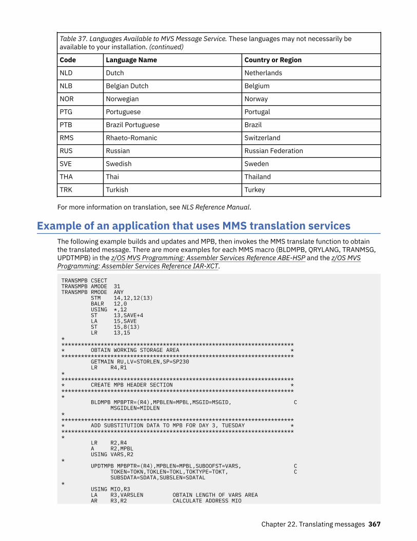
Table 37. Languages Available to MVS Message Service. These languages may not necessarily beavailable to your installation. (continued)
Code Language Name Country or Region
NLD Dutch Netherlands
NLB Belgian Dutch Belgium
NOR Norwegian Norway
PTG Portuguese Portugal
PTB Brazil Portuguese Brazil
RMS Rhaeto-Romanic Switzerland
RUS Russian Russian Federation
SVE Swedish Sweden
THA Thai Thailand
TRK Turkish Turkey
For more information on translation, see NLS Reference Manual.
Example of an application that uses MMS translation servicesThe following example builds and updates and MPB, then invokes the MMS translate function to obtainthe translated message. There are more examples for each MMS macro (BLDMPB, QRYLANG, TRANMSG,UPDTMPB) in the z/OS MVS Programming: Assembler Services Reference ABE-HSP and the z/OS MVSProgramming: Assembler Services Reference IAR-XCT.
TRANSMPB CSECTTRANSMPB AMODE 31TRANSMPB RMODE ANY STM 14,12,12(13) BALR 12,0 USING *,12 ST 13,SAVE+4 LA 15,SAVE ST 15,8(13) LR 13,15************************************************************************* OBTAIN WORKING STORAGE AREA ************************************************************************ GETMAIN RU,LV=STORLEN,SP=SP230 LR R4,R1************************************************************************* CREATE MPB HEADER SECTION ************************************************************************* BLDMPB MPBPTR=(R4),MPBLEN=MPBL,MSGID=MSGID, C MSGIDLEN=MIDLEN************************************************************************* ADD SUBSTITUTION DATA TO MPB FOR DAY 3, TUESDAY ************************************************************************* LR R2,R4 A R2,MPBL USING VARS,R2* UPDTMPB MPBPTR=(R4),MPBLEN=MPBL,SUBOOFST=VARS, C TOKEN=TOKN,TOKLEN=TOKL,TOKTYPE=TOKT, C SUBSDATA=SDATA,SUBSLEN=SDATAL* USING MIO,R3 LA R3,VARSLEN OBTAIN LENGTH OF VARS AREA AR R3,R2 CALCULATE ADDRESS MIO
Chapter 22. Translating messages 367

LA R5,MLEN GET LENGTH OF MIO AR R5,R3 CALCULATE ADDRESS OF OUTPUT BUFFER ST R4,VARSINBF CREATE ADDRESS LIST************************************************************************* ISSUE TRANSLATE TO OBTAIN MESSAGE TEXT REPRESENTED BY THE ** CREATED MPB ************************************************************************* TRANMSG MIO=MIO,MIOL=MIOLEN,INBUF=(VARSINBF,ONE), C OUTBUF=(R5),OUTBUFL=OUTAREAL,LANGCODE=LC************************************************************************* FREE STORAGE AREA ************************************************************************* FREEMAIN RU,LV=STORLEN,SP=SP230,A=(4)* L 13,SAVE+4 LM 14,12,12(13) BR 14 DROP***********************************************************************MPBL DC A(MPBLEN)MSGID DC CL10'MSGID2'MIDLEN DC A(MIDL)TOKN DC CL3'DAY'TOKL DC F'3'TOKT DC CL1'3'SDATA DC CL1'3'SDATAL DC A(SDL)MIOLEN DC A(MLEN)OUTAREAL DC A(STORLEN-(MPBLEN+VARSLEN+MLEN))ONE DC F'1'LC DC CL3'JPN'SAVE DC 18F'0'SP230 EQU 230STORLEN EQU 512SDL EQU 6MIDL EQU 6MPBLEN EQU (MPBVDAT-MPB)+(MPBMID-MPBMSG)+(MPBSUB-MPBSB)+MIDL+SDLMLEN EQU (MIOVDAT-MIO)+MIOMSGLR1 EQU 1R2 EQU 2R3 EQU 3R4 EQU 4R5 EQU 5*********************************************************************** DSECT CNLMMPB CNLMMCA CNLMMIOVARS DSECTVARSINBF DS FVARSAREA DS CL24VARSLEN EQU *-VARS END TRANSMPB
368 z/OS: z/OS MVS Assembler Services Guide

Chapter 23. Data compression and expansionservices
z/OS supports compression using two different algorithms. The first algorithm exploits the occurrence ofrepeated characters in a data stream. Encoded data contains a combination of symbols that representstrings of repeated characters and the original characters that are not repeated. The CSRCESRV serviceuses this algorithm to compress data.
Data that contains many repeat characters can exploit these services most effectively. Examples include:
• Data sets with fixed field lengths that might contain many blanks• 80-byte source code images of assembler language programs.
Using these services with other types of data might not result in appreciable data volume reduction. Insome cases, data volume might even be increased.
The second algorithm encodes data by replacing strings of characters with shorter fixed-length symbols.A key component of this technique is the symbol table, usually referred to as a dictionary. Encoded datacontains symbols that correspond to entries in the dictionary. The CSRCMPSC service uses this algorithmto compress data.
This service requires more storage than the CSRCESRV services, but is a good choice if you know whatyour data looks like and storage is not a concern.
Services provided by CSRCESRVData compression and expansion services, which your program invokes through the CSRCESRV macro, aredescribed as follows:
• Data Compression Service
This service compresses a block of data that you identify and stores that data in compressed form in anoutput area. The service uses an algorithm called run length encoding, which is a compressiontechnique that compresses repeating characters, such as blanks. In some cases, the service uses aninterim work area.
• Data Expansion Service
This service expands a block of data that you identify; the data must have been compressed by the datacompression service. The data expansion service reverses the algorithm that the data compression service used, and stores the data in its original form in an output area. In some cases, the service usesan interim work area.
• Query Service
This service queries the system to determine the following:
– Whether data compression is supported by the system currently installed– The size of the work area required by the compression or expansion service.
To use the data compression and data expansion services, you need the information that the queryservice provides. Invoke the query service before invoking either the data compression or dataexpansion services.
Note: These services do not provide a recovery routine (for example, ESTAE or FRR) because it would notcontribute to reliability or availability.
© Copyright IBM Corp. 1988, 2020 369

Using these servicesThe data compression, data expansion, and query services resides in SYS1.LPALIB. Your program caninvoke these services by using the CSRCESRV macro.
See z/OS MVS Programming: Assembler Services Reference ABE-HSP for complete instructions on how touse the CSRCESRV macro.
To invoke the data compression or data expansion services, follow these steps:
1. Invoke the query service by coding the CSRCESRV macro specifying SERVICE=QUERY. The macroreturns the information you need to invoke the data compression or data expansion service.
2. If you plan to compress data, check the information returned to ensure that compression is supported.3. Invoke the data compression service (or the data expansion service) by coding the CSRCESRV macro
specifying SERVICE=COMPRESS (or SERVICE=EXPAND).
Services provided by CSRCMPSCCompression takes an input string of data and, using a data area called a dictionary, produces an outputstring of compression symbols. Each symbol represents a string of one or more characters from the input.
Expansion takes an input string of compression symbols and, using a dictionary, produces an output stringof the characters represented by those compression symbols.
Parameters for the CSRCMPSC macro are in an area mapped by DSECT CMPSC of the CSRYCMPS macroand specified by the CBLOCK parameter of the CSRCMPSC macro. This area contains such information as:
• The address, ALET, and length of a source area. The source area contains the data to be compressed fora compression operation, or to be expanded for an expansion operation.
• The address, ALET, and length of a target area. After the macro runs, the target area contains thecompressed data for a compression operation, or the expanded data for an expansion operation.
• An indication of whether to perform compression or expansion.• The address and format of a dictionary to be used to perform the compression or expansion. The
dictionary must be in the same address space as the source area.
Compressing and expanding data is described in the following topics:
• “Compression and expansion dictionaries” on page 370• “Building the CSRYCMPS area” on page 371• “Determining if the CSRCMPSC macro can be issued on a system” on page 373
To help you use the compression services, the SYS1.SAMPLIB system library contains the following REXXexecs:
• CSRBDICT for building example dictionaries• CSRCMPEX for measuring the degree of compression that the dictionaries provide
When running on VM, two analogous macros are available:
• CSRBDICV for building example dictionaries• CSRCMPEV for measuring the degree of compression that the dictionaries provide
The prologs of the execs tell how to use them. For additional information about compression and usingthe execs, see Enterprise Systems Architecture/390 Data Compression.
Compression and expansion dictionariesTo accomplish compression and expansion, the macro uses two dictionaries: the compression dictionaryand the expansion dictionary. These dictionaries are related logically and physically. When you expanddata that has been compressed, you want the result to match the original data. Thus the dictionaries arecomplementary. When compression is done, the expansion dictionary must immediately follow the
370 z/OS: z/OS MVS Assembler Services Guide

compression dictionary, because the compression algorithm examines entries in the expansion dictionary.
Each dictionary consists of 512, 1024, 2048, 4096, or 8192 8-byte entries and begins on a pageboundary. When the system determines or uses a compression symbol, the symbol is 9, 10, 11, 12, or 13bits long, with the length corresponding to the number of entries in the dictionary. Specify the size of thedictionary in the CMPSC_SYMSIZE field of the CSRYCMPS mapping macro:SYMSIZE
Meaning1
Symbol size 9 bits, dictionary has 512 entries2
Symbol size 10 bits, dictionary has 1024 entries3
Symbol size 11 bits, dictionary has 2048 entries4
Symbol size 12 bits, dictionary has 4096 entries5
Symbol size 13 bits, dictionary has 8192 entries
The value of CMPSC_SYMSIZE represents the size of the compression and expansion dictionaries. Forexample, if CMPSC_SYMSIZE is 512, then the size of the compression dictionary is 512 and the size of theexpansion dictionary is 512.
Building the CSRYCMPS areaThe CSRYCMPS area is mapped by the CSRYCMPS mapping macro and is specified in the CBLOCKparameter of the CSRCMPSC macro. The area consists of 7 words that should begin on a word boundary.Unused bits in the first word must be set to 0.
• Set 4-bit field CMPSC_SYMSIZE in byte CMPSC_FLAGS_BYTE2 to a number from 1 to 5 to indicate boththe number of entries in the dictionary and the size of a compressed symbol.
• If expanding, turn on bit CMPSC_EXPAND in byte CMPSC_FLAGS_BYTE2. Otherwise, make sure that thebit is off.
• Whether compressing or expanding, you can turn on bit CMPSC_ZeroPaddingOK. This bit indicates thatzero padding of the output operand on the right up to the operand length, and up to a model-dependantintegral boundary is acceptable. Specifying this bit might help the performance of the operation. The bitis ignored if the machine does not support the capability, so the bit can be set unconditionally.
• Set field CMPSC_DICTADDR to the address of the necessary dictionary. If compressing, this should bethe compression dictionary, which must be immediately followed by the expansion dictionary. Ifexpanding, this should be the expansion dictionary. In either case, the dictionary must begin on a pageboundary, as the low order 12 bits of the address are assumed to be 0 when determining the address ofthe dictionary.
If running in AR mode, set field CMPSC_SOURCEALET to the ALET of the necessary dictionary. Note thatthe input area is also accessed using this ALET. If not in AR mode, make sure that the field contains 0.
Using the linkage editor can help you get the dictionary on the proper boundary. For example, you mayhave an object deck for each compression dictionary (CD), and expansion dictionary (ED), and a DDstatement for file OBJS, which represents the library containing the object decks. The followinginstructions linkage editor control statements define a dictionary with the name DICT that, whenloaded, will have the compression dictionary followed by the expansion dictionary, and will begin on apage boundary.
ORDER CD(P),EDINCLUDE OBJS(CD)INCLUDE OBJS(ED)NAME DICT(R)
Chapter 23. Data compression and expansion services 371

• In most cases, make sure that 3-bit field CMPSC_BITNUM in byte CMPSC_DICTADDR_BYTE3 is zero.This field has the following meaning:
– If compressing, place the first compression symbol at this bit in the leftmost byte of the targetoperand. Normally this field should be set to 0 for the start of compression.
– If expanding, expand beginning with the compression symbol that begins with this bit in the leftmostbyte of the source operand. Normally this field should be set to the value used for the start ofcompression.
• Set word CMPSC_TARGETADDR to the address of the output area. For compression, the output areacontains the compressed data; for expansion, it contains the expanded data.
If running in AR mode, set field CMPSC_TARGETALET to the ALET of the output area. If not in AR mode,make sure that the field contains 0.
• Set word CMPSC_TARGETLEN to the length of the output area.• Set word CMPSC_SOURCEADDR to the address of the input area. For compression, the input area
contains the data to be compressed; for expansion, it contains the compressed data.
If running in AR mode, set field CMPSC_SOURCEALET to the ALET of the input area. Note that thedictionary will also be accessed using this ALET. If not in AR mode, make sure that the field contains 0.
• Set word CMPSC_SOURCELEN to the length of the input area. For expansion, the length should be thedifference between CMPSC_TARGETLEN at the completion of compression and CMPSC_TARGETLEN atthe start of compression, increased by 1 if field CMPSC_BITNUM was nonzero upon completion ofcompression.
• Set word CMPSC_WORKAREAADDR to the address of a 192-byte work area for use by the CSRCMPSCmacro. The work area should begin on a doubleword boundary. This area does not need to be providedand the field does not have to be set if your code has verified that the hardware CMPSC instruction ispresent. The program can do the verification by checking that bit CVTCMPSH in mapping macro CVT ison.
When the CSRCMPSC service returns, it has updated the input CSRYCMPS area as follows:
• CMPSC_FLAGS is unchanged.• CMPSC_DICTADDR is unchanged, but bits CMPSC_BITNUM in field CMPSC_DICTADDR_BYTE3 are set
according to the last-processed compression symbol.• CMPSC_TARGETADDR is increased by the number of output bytes processed.• CMPSC_TARGETLEN is decreased by the number of output bytes processed.• CMPSC_SOURCEADDR is increased by the number of input bytes processed.• CMPSC_SOURCELEN is decreased by the number of input bytes processed.• CMPSC_WORKAREA is unchanged.
The target/source address and length fields are updated analogously to the corresponding operands ofthe MVCL instruction, so that you can tell upon completion of the operation how much data wasprocessed and where you might want to resume if you wanted to continue the operation.
Suppose that you had compressed a large area but wanted to expand it back into a small area of 80-byterecords. You might do the expansion as follows:
LA 2,MYCBLOCK USING CMPSC,2 XC CMPSC(CMPSC_LEN),CMPSC OI CMPSC_FLAGS_BYTE2,CMPSC_SYMSIZE_1 OI CMPSC_FLAGS_BYTE2,CMPSC_EXPAND L 3,EDICTADDR Address of expansion dictionary ST 3,CMPSC_DICTADDR Set dictionary address L 3,EXPADDR ST 3,CMPSC_SOURCEADDR Set compression area L 3,EXPLEN ST 3,CMPSC_SOURCELEN Set compression length LA 3,WORKAREA ST 3,CMPSC_WORKAREAADDR Set work area addressMORE DS 0H Label to continue*
372 z/OS: z/OS MVS Assembler Services Guide

* Your code to allocate an 80-byte output area would go here* ST x,CMPSC_TARGETADDR Save target expansion area LA 3,80 Set its length ST 3,CMPSC_TARGETLEN Set expansion length CSRCMPSC CBLOCK=CMPSC Expand C 15,=AL4(CMPSC_RETCODE_TARGET) Not done, target used up BE MORE Continue with operation DROP 2 . . DS 0F Align parameter on word boundaryMYCBLOCK DS (CMPSC_LEN)CL1 CBLOCK ParameterEXPADDR DS A Input expansion areaEXPLEN DS F Length of expansion areaEDICTADDR DS A Address of expansion dictionary DS 0D Doubleword align work areaWORKAREA DS CL192 Work area CSRYCMPS , Get mapping and equates
Note that this code loops while the operation is not complete, allocating a new 80-byte output record. Itdoes not have to update the CMPSC_BITNUM, CMPSC_SOURCEADDR, or CMPSC_SOURCELEN fields,because the service sets them up for continuation of the original operation.
If running in AR mode, the example would also have set the CMPSC_TARGETALET andCMPSC_SOURCEALET fields. The XC instruction zeroed those fields as needed when running in primaryASC mode.
Determining if the CSRCMPSC macro can be issued on a systemDo the following to tell if the system contains the software or hardware to run a CSRCMPSC macro:
1. Determine if CSRCMPSC is available, by running the following:
L 15,16 Get CVT address USING CVT,15 Set up addressability to the CVT TM CVTFLAG2,CVTCMPSC Is CSRCMPSC available? BZ NO_CSRCMPSC Branch if not available* Compression feature is available . .NO_CSRCMPSC DS 0H
2. Determine if the CMPSC hardware instruction is available, by running the following:
L 15,16 Get CVT address USING CVT,15 Set up addressability to the CVT TM CVTFLAG2,CVTCMPSH Is CMPSC hardware available? BZ NO_CMPSC_HARDWARE Branch if not available* CMPSC hardware is available . .NO_CMPSC_HARDWARE DS 0H
The remaining three topics in this chapter describe compression and expansion processing and thedictionary entries in much greater detail. If you plan to use the CSRBDICT exec to build your dictionary,you do not need to read these topics. If you plan to build your own dictionary, you will want to read:
• “Compression processing” on page 373• “Expansion processing” on page 374• “Dictionary entries” on page 374
Compression processingThe compression dictionary consists of a specified number of 8-byte entries. The first 256 dictionaryentries correspond to the 256 possible values of a byte and are referred to as alphabet entries. Theremaining entries are arranged in a downward tree, with the alphabet entries being the topmost entries inthe tree. That is, an alphabet entry may be a parent entry and contain the index of the first of one or more
Chapter 23. Data compression and expansion services 373

contiguous child entries. A child entry may, in turn, be a parent and point to its own children. Each entrymay be identified by its index, meaning the positional number of the entry in the dictionary; the first entryhas an index of 0.
An alphabet entry represents one character. A nonalphabet entry represents all of the charactersrepresented by its ancestors and also one or more additional characters called extension characters. Forcompression, the system uses the first character of an input string as an index to locate the correspondingalphabet entry. Then the system compares the next character or characters of the string against theextension character or characters represented by each child of the alphabet entry until a match is found.The system repeats this process using the children of the last matched entry, until the last possible matchis found, which might be a match on only the alphabet entry. The system uses the index of the lastmatched entry as the compression symbol.
The first extension character represented by a child entry exists as either a child character in the parent oras a sibling character. A parent can contain up to four or five child characters. If the parent has morechildren than the number of child characters that can be in the parent, a dictionary entry named a siblingdescriptor follows the entry for the last child character in the parent. The sibling descriptor can contain upto six additional child characters, and a dictionary entry named a sibling descriptor extension can containeight more child characters for a total of fourteen. These characters are called sibling characters. Thecorresponding additional child entries follow the sibling descriptor. If necessary, another siblingdescriptor follows the additional child entries, and so forth. The dictionary entries that are not siblingdescriptors or sibling descriptor extensions are called character entries.
If a nonalphabet character entry represents more than one extension character, the extension charactersafter the first are in the entry; they are called additional extension characters. The first extensioncharacter exists as a child character in the parent or as a sibling character in a sibling descriptor or siblingdescriptor extension. The nonalphabet character entries represent either:
• If the entry has no children or one child, from one to five extension characters.• If the entry has more than one child, one or two extension characters. If the entry represents one
extension character, it can contain five child characters. If it represents two extension characters, it cancontain four child characters.
Expansion processingThe dictionary used for expansion also consists of a specified number of 8-byte entries. The two types ofentries used for expansion are:
• Unpreceded entries• Preceded entries
The compression symbol, which is an index into the dictionary, locates that index's dictionary entry. Thesymbol represents a character string of up to 260 characters. If the entry is an unpreceded entry, theexpansion process places at offset 0 from the current processing point the characters designated by thatentry. Note that the first 256 correspond to the 256 possible values of a byte and are assumed todesignate only the single character with that byte value.
If the entry is a preceded entry, the expansion process places the designated characters at the specifiedoffset from the current processing point. It then uses the information in that entry to locate the precedingentry, which may be either an unpreceded or a preceded entry, and continues as described previously.
The sibling descriptor extension entries described earlier are also physically located within the expansiondictionary.
Dictionary entriesThe following notation is used in the diagrams of dictionary entries:{cc}
Character may be present
374 z/OS: z/OS MVS Assembler Services Guide

...The preceding field may be repeated
Compression dictionary entriesCompression entries are mapped by DSECTs in macro CSRYCMPD.
The first four entries that follow give the possible values for bits 0-2, which are designated CCT.
Character entry generic form (DSECT CMPSCDICT_CE)
CCTA 3-bit field (CMPSCDICT_CE_CHILDCT) specifying the number of children. The total number ofchildren plus additional extension characters is limited to 5. If this field plus the number of additionalcharacters is 6, it indicates that, in addition to the maximum number of children for this entry, there isa sibling descriptor entry that describes additional children. The sibling descriptor entry is located atdictionary entry CMPSCDICT_CE_FIRSTCHILDINDEX plus the value of CMPSCDICT_CE_CHILDCT. Thevalue of CMPSCDICT_CE_CHILDCT plus the number of additional extension characters must notexceed 6.
Character entry CCT=0 (DSECT CMPSCDICT_CE)
ACTA 3-bit field (CMPSCDICT_CE_AECCT) indicating the number of additional extension characters in theentry. Its value must not exceed 4. This field must be 0 in an alphabet entry.
ECAn additional extension character. The 5-character field CMPSCDICT_CE_CHILDCHAR is provided tohold the additional extension characters followed by the child characters.
Character entry CCT=1 (DSECT CMPSCDICT_CE)
XXXXXA 5-bit field (CMPSCDICT_CE_EXCHILD) with the first bit indicating whether it is necessary to examinethe character entry for the child character (looking either for additional extension characters or morechildren). The other bits are ignored when CCT=1.
ACTA 3-bit field (CMPSCDICT_CE_AECCT) indicating the number of additional extension characters. Itsvalue must not exceed 4. This field must be 0 in an alphabet entry.
CINDEXA 13-bit field (CMPSCDICT_CE_FIRSTCHILDINDEX) indicating the index of the first child. The index forchild n is then CMPSCDICT_CE_FIRSTCHILDINDEX + n-1.
ECAn additional extension character. The 5-character field CMPSCDICT_CE_CHILDCHAR is provided tohold the additional extension characters followed by the child characters.
Chapter 23. Data compression and expansion services 375

CCChild character, at bit n = 24 + (ACT * 8). The 5-character field CMPSCDICT_CE_CHILDCHAR isprovided to hold the additional extension characters followed by the child characters.
Character entry CCT>1 (DSECT CMPSCDICT_CE)
CCTA 3-bit field (CMPSCDICT_CE_CHILDCT) specifying the number of children. For this case, becauseCCT>1, the range for CCT is 2 to 6 if D=0 or 2 to 5 if D=1. If this field plus the value of D is 6, itindicates that, in addition to the maximum number of children for this entry (4 if D=1, 5 if D=0), thereis a sibling descriptor entry that describes additional children. The sibling descriptor entry is locatedat dictionary entry CMPSCDICT_CE_FIRSTCHILDINDEX plus the value of CMPSCDICT_CE_CHILDCT.
XXXXXA 5-bit field (CMPSCDICT_CE_EXCHILD) with a bit for each child in the entry. The field indicateswhether it is necessary to examine the character entry for the child character (looking either foradditional extension characters or more children). The bit is ignored if the child does not exist.
YYA 2-bit field (CMPSCDICT_CE_EXSIB) providing examine-child bits for the 13th and 14th siblingsdesignated by the first sibling descriptor for children of this entry. The bit is ignored if the child doesnot exist. Note that this is a subfield of CMPSCDICT_CE_AECCT. Do not set both this field and fieldCMPSCDICT_CE_AECCT in a character entry.
DA 1-bit field (CMPSCDICT_CE_ADDEXTCHAR) indicating whether there is an additional extensioncharacter. Note that this is a subfield of CMPSCDICT_CE_AECCT. Do not set both this field and fieldCMPSCDICT_CE_AECCT in a character entry. This bit must be 0 in an alphabet entry.
CINDEXA 13-bit field (CMPSCDICT_CE_FIRSTCHILDINDEX) indicating the index of the first child. The index forchild n is CMPSCDICT_CE_FIRSTCHILDINDEX + n-1.
ECAn additional extension character. The 5-character field CMPSCDICT_CE_CHILDCHAR is provided tohold the additional extension character followed by the child characters. There is no additionalextension character if D=0.
CCChild character. The 5-character field CMPSCDICT_CE_CHILDCHAR is provided to hold the additionalextension characters followed by the child characters. The first child character is at bit n = 24 + (D *8).
Alphabet entries (DSECT CMPSCDICT_CE)The alphabet entries have the same mappings as character entries but without the additional extensioncharacters. The character entries are “Character entry generic form (DSECT CMPSCDICT_CE)” on page375, “Character entry CCT=0 (DSECT CMPSCDICT_CE)” on page 375, “Character entry CCT=1 (DSECTCMPSCDICT_CE)” on page 375, and “Character entry CCT>1 (DSECT CMPSCDICT_CE)” on page 376.
Format 1 sibling descriptor (DSECT CMPSCDICT_SD)
376 z/OS: z/OS MVS Assembler Services Guide

SCTA 4-bit field (CMPSCDICT_SD_SIBCT) specifying the number of sibling characters. The number ofsibling characters is limited to 14. If this field is 15, it indicates that there are 14 sibling charactersassociated with this entry and that there is another sibling descriptor entry, which describesadditional children. That sibling descriptor entry is located at dictionary entry this-sibling-descriptor-index + 15. If there are 1 to 6 sibling characters, they are contained in this entry, and the dictionaryentries for those characters are located at this-sibling-descriptor-index + n, where n is 1 to 6. If thereare 7 to 14 sibling characters, the first 6 are as described previously, and characters 7 through 14 arelocated in the expansion dictionary entry. (See “Sibling descriptor extension entry (DSECTCMPSCDICT_SDE)” on page 378.) The index of the character entry is this-sibling-descriptor-index.The number of sibling characters should not be 0.
YYYYYYYYYYYYA 12-bit field (CMPSCDICT_SD_EXSIB), one for each sibling character, indicating whether to examinethe character entries for sibling characters 1 through 12. Recall that the examine-sibling indicator forsibling characters 13 and 14 for the first sibling descriptor is in the character entry fieldCMPSCDICT_CE_EXSIB. If this is not the first sibling descriptor for the child entry, then the characterentries for sibling characters 13 and 14 are examined irregardless. The bit is ignored if the siblingdoes not exist.
SCSibling character. Sibling characters 8 through 14 are in the expansion dictionary. (See “Siblingdescriptor extension entry (DSECT CMPSCDICT_SDE)” on page 378.) The 6-character field(CMPSCDICT_SD_CHILDCHAR) is provided to contain the sibling characters. The index of thecharacter entry for sibling character n is this-sibling-descriptor-index + n-1.
Expansion dictionary entriesExpansion entries are mapped by DSECTs in macro CSRYCMPD.
Unpreceded entry (DSECT CMPSCDICT_UE)
CSLA 3-bit field (CMPSCDICT_UE_COMPSYMLEN) indicating the number of characters contained inCMPSCDICT_UE_CHARS. These characters will be placed at offset 0 in the expanded output. This fieldshould not have a value of 0.
ECExpansion character. The 7-character field (CMPSCDICT_UE_CHARS) is provided to contain theexpansion characters.
Preceded entry (DSECT CMPSCDICT_PE)
PSLA 3-bit field (CMPSCDICT_PE_PARTSYMLEN) indicating the number of characters contained inCMPSCDICT_PE_CHARS. These characters will be placed at the offset indicated byCMPSCDICT_PE_OFFSET in the expanded output. This field must not be 0, because 0 indicates anunpreceded entry.
PrecIndexA 13-bit field (CMPSCDICT_UE_PRECENTINDEX) indicating the index of the dictionary entry withwhich processing is to continue.
Chapter 23. Data compression and expansion services 377
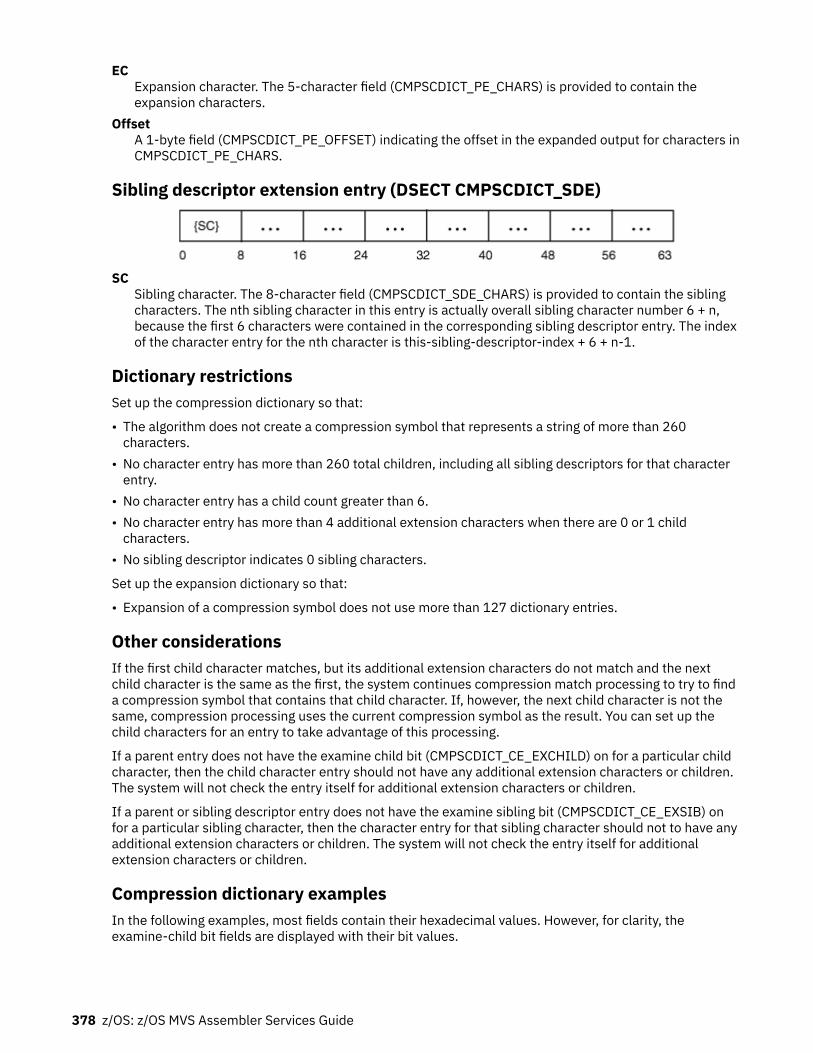
ECExpansion character. The 5-character field (CMPSCDICT_PE_CHARS) is provided to contain theexpansion characters.
OffsetA 1-byte field (CMPSCDICT_PE_OFFSET) indicating the offset in the expanded output for characters inCMPSCDICT_PE_CHARS.
Sibling descriptor extension entry (DSECT CMPSCDICT_SDE)
SCSibling character. The 8-character field (CMPSCDICT_SDE_CHARS) is provided to contain the siblingcharacters. The nth sibling character in this entry is actually overall sibling character number 6 + n,because the first 6 characters were contained in the corresponding sibling descriptor entry. The indexof the character entry for the nth character is this-sibling-descriptor-index + 6 + n-1.
Dictionary restrictionsSet up the compression dictionary so that:
• The algorithm does not create a compression symbol that represents a string of more than 260characters.
• No character entry has more than 260 total children, including all sibling descriptors for that characterentry.
• No character entry has a child count greater than 6.• No character entry has more than 4 additional extension characters when there are 0 or 1 child
characters.• No sibling descriptor indicates 0 sibling characters.
Set up the expansion dictionary so that:
• Expansion of a compression symbol does not use more than 127 dictionary entries.
Other considerationsIf the first child character matches, but its additional extension characters do not match and the nextchild character is the same as the first, the system continues compression match processing to try to finda compression symbol that contains that child character. If, however, the next child character is not thesame, compression processing uses the current compression symbol as the result. You can set up thechild characters for an entry to take advantage of this processing.
If a parent entry does not have the examine child bit (CMPSCDICT_CE_EXCHILD) on for a particular childcharacter, then the child character entry should not have any additional extension characters or children.The system will not check the entry itself for additional extension characters or children.
If a parent or sibling descriptor entry does not have the examine sibling bit (CMPSCDICT_CE_EXSIB) onfor a particular sibling character, then the character entry for that sibling character should not to have anyadditional extension characters or children. The system will not check the entry itself for additionalextension characters or children.
Compression dictionary examplesIn the following examples, most fields contain their hexadecimal values. However, for clarity, theexamine-child bit fields are displayed with their bit values.
378 z/OS: z/OS MVS Assembler Services Guide

Example 1Suppose the dictionary looks like the following:Hexadecimal Entry
DescriptionC1
Alphabet entry for character A; 2 child characters B and C. The first child index is X'100'.100
Entry for character B; no additional extension characters; no children.101
Entry for character C; additional extension character 1; 2 child characters D and E. The first child indexis X'200'.
200Entry for character D; 2 additional extension characters 1 and 2; no children.
201Entry for character E; 4 additional extension characters 1, 2, 3, and 4; no children.
If the input string is AD, the output string will consist of 2 compression symbols: one for A and one for D.When examining the dictionary entry for character A, the system determines that none of A's childrenmatch the next input character, D, and so returns the compression symbol for A. When examining thedictionary entry for character D, the system determines that it has no children, and so returns thecompression symbol for D.
If the input string is AB, the output string will consist of 1 compression symbol for both input characters.When examining the dictionary input for character A, the system determines that A's first child charactermatches the next input character, B, and so looks at entry X'100'. Because that entry has no additionalextension characters, a match is determined. Because there are no further input characters, the scanconcludes.
If the input string is AC, the output string will consist of 2 compression symbols: one for A and one for C.When examining the dictionary input for character A, the system determines that A's second childcharacter matches the next input character, C, and so looks at entry X'101'. Because that entry has an
Chapter 23. Data compression and expansion services 379

additional extension character, but the input string does not contain this character, no match is made, andthe output is the compression symbol for A. Processing character C results in the compression symbol forC.
If the input string is AC1, the output string will consist of 1 compression symbol. When examining thedictionary input for character A, the system determines that A's second child character matches the nextinput character, C, and so looks at entry X'101'. Because that entry has an additional extension character,and the input string does contain this character, 1, a match is made, and the output is the compressionsymbol for AC1.
Similarly, the set of input strings longer than one character compressed by this dictionary are:Hexadecimal Symbol
String100
AB101
AC1200
AC1D12201
AC1E1234
The compression symbol is the index of the dictionary entry. Based on this, you can see that theexpansion dictionary must result in the reverse processing; for example, if a compression symbol ofX'201' is found, the output must be the string AC1E1234. See “Expansion dictionary example” on page383 for expansion dictionary processing.
Example 2 for more than 5 childrenSuppose the dictionary looks like the following:Hexadecimal Entry
DescriptionC2
Alphabet entry for character B; child count of 6 (indicating 5 children plus a sibling descriptor); firstchild index is X'400', children are 1, 2, 3, 4, and 5.
400Entry for character 1; no additional extension characters; no children.
401-404Entries for characters 2 through 5; no additional extension characters; no children.
405Sibling descriptor; child count of 15, which indicates 14 children plus another sibling descriptor;sibling characters A, B, C, D, E, and F.
405Sibling descriptor extension. In the expansion dictionary entry X'405', the sibling characters are G,H, I, J, K, L, M, and N.
406Entry for character A; no additional extension characters; no children.
407-413Entries for characters B through N; no additional extension characters; no children.
414Next sibling descriptor; child count of 2; child characters O and P.
415Entry for character O; no additional extension characters; no children.
380 z/OS: z/OS MVS Assembler Services Guide

416Entry for character P; no additional extension characters; no children.
The set of input strings longer than one character compressed by this dictionary are:Hexadecimal Symbol
String400-404
B1, B2, B3, B4, B5406-40B
BA, BB, BC, BD, BE, BF40C-413
BG, BH, BI, BJ, BK, BL, BM, BN
Chapter 23. Data compression and expansion services 381
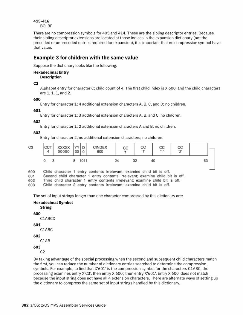
415-416BO, BP
There are no compression symbols for 405 and 414. These are the sibling descriptor entries. Becausetheir sibling descriptor extensions are located at those indices in the expansion dictionary (not thepreceded or unpreceded entries required for expansion), it is important that no compression symbol havethat value.
Example 3 for children with the same valueSuppose the dictionary looks like the following:Hexadecimal Entry
DescriptionC3
Alphabet entry for character C; child count of 4. The first child index is X'600' and the child charactersare 1, 1, 1, and 2.
600Entry for character 1; 4 additional extension characters A, B, C, and D; no children.
601Entry for character 1; 3 additional extension characters A, B, and C; no children.
602Entry for character 1; 2 additional extension characters A and B; no children.
603Entry for character 2; no additional extension characters; no children.
The set of input strings longer than one character compressed by this dictionary are:Hexadecimal Symbol
String600
C1ABCD601
C1ABC602
C1AB603
C2
By taking advantage of the special processing when the second and subsequent child characters matchthe first, you can reduce the number of dictionary entries searched to determine the compressionsymbols. For example, to find that X'601' is the compression symbol for the characters C1ABC, theprocessing examines entry X'C3', then entry X'600', then entry X'601'. Entry X'600' does not matchbecause the input string does not have all 4 extension characters. There are alternate ways of setting upthe dictionary to compress the same set of input strings handled by this dictionary.
382 z/OS: z/OS MVS Assembler Services Guide

Expansion dictionary exampleSuppose the expansion dictionary looks like the following:Hexadecimal Entry
DescriptionC1
Alphabet entry for character A. This by definition is an unpreceded entry.101
A preceded entry, with characters C and 1; with preceding entry index of X'C1'; offset of 1.201
A preceded entry, with characters E, 1, 2, 3, and 4; with preceding entry index of X'101'; offset of 3.
When processing an input compression symbol of X'201':
• Characters E1234 are placed at offset 3, and processing continues with entry X'101'.• Characters C1 are placed at offset 1, and processing continues with entry X'C1'.• Character A is placed at offset 0.
The expansion results in the 8 characters A, C, 1, E, 1, 2, 3, and 4 placed in the output string.
Chapter 23. Data compression and expansion services 383

384 z/OS: z/OS MVS Assembler Services Guide

Chapter 24. Accessing unit control blocks (UCBs)
Each device in a configuration is represented by a unit control block (UCB). In a dynamic configurationenvironment, a service obtaining UCB information needs to be able to detect any changes in theconfiguration that could affect the returned information. The MVS I/O configuration token provides thiscapability. You can scan UCBs with the UCBSCAN macro to obtain information about the devices in theconfiguration. You can also use the UCBINFO macro to obtain device information from a UCB.
The eligible device table (EDT) contains the definitions for the installation's device groups. The EDTINFOmacro allows you to obtain information from the EDT.
Detecting I/O configuration changesYou can use the MVS I/O configuration token to detect I/O configuration changes. The MVS I/Oconfiguration token is a 48-byte token that uniquely identifies an I/O configuration to the system. Thetoken will change whenever the software configuration definition changes. Thus, if your program obtainsthe current MVS I/O configuration token and compares it to one previously obtained, the program candetermine whether there has been a change in the I/O configuration: If the tokens do not match, the I/Oconfiguration has changed.
An optional parameter, IOCTOKEN, is available with the UCBSCAN macro. Specifying IOCTOKEN ensuresthat the system will notify the caller through a return code and will not return any data if the current I/Oconfiguration is not consistent with the configuration represented by the token specified as input by thecaller.
Use the following ways to obtain the current MVS I/O configuration token:
• Issue the IOCINFO macro. • Issue the UCBSCAN macro, setting the input specified by the IOCTOKEN parameter to binary zeroes.
The macro will then return the current I/O configuration token at the start of the scan.• Issue EDTINFO macro, setting the input specified by the IOCTOKEN parameter to binary zeroes.
Use of the MVS I/O configuration token can help prevent data inconsistencies that might occur if the I/Oconfiguration changes between the time the caller obtained the token and the time the service returns theinformation. For example, you can use the configuration token to determine whether the I/O configurationchanges during a UCB scan. If the IOCTOKEN parameter is specified with UCBSCAN, the caller will benotified through a return code if the set of UCBs changes while the scan is in progress. Checking for thisreturn code allows the caller to restart the scan to ensure that copies of all UCBs in the currentconfiguration are obtained.
An unauthorized program can use the MVS I/O configuration token to regularly check whether aconfiguration change has occurred, as in the following example:
• The program issues the IOCINFO macro to obtain the MVS I/O configuration token.• The program sets a time interval that is to expire in 10 minutes, using the STIMER macro.• When the time interval expires, the user-specified timer exit routine gets control and issues the
IOCINFO macro to obtain the MVS I/O configuration token that is current at this later time.• The program compares the newly-obtained token with the original one.• If the tokens match, no I/O configuration change has occurred, and the program resets the time interval
for another 10 minutes to check again at that time.• If the tokens do not match, a configuration change has occurred. The program then rebuilds its control
structures by using the UCBSCAN macro, specifying the IOCTOKEN parameter to check for any furtherI/O configuration changes while the rebuilding process is in progress. After the control structures arerebuilt for the new I/O configuration, the program resets the time interval for 10 minutes to check againfor I/O configuration changes.
© Copyright IBM Corp. 1988, 2020 385

Scanning UCBsYou can use the UCBSCAN macro with the COPY keyword to scan UCBs. On each invocation, UCBSCANmay return, in caller-supplied storage areas, a copy of one or more of the following UCB segments:
• UCB common segment• UCB common extension segment• UCB prefix extension segment• UCB device class extension segment
The scan can include all UCBs in the system, or be restricted to a specific device class. For example, youcould use UCBSCAN to find all DASD devices currently defined to the configuration. It is also possible torestrict the scan to UCBs for static and installation-static devices, or to include UCBs for dynamic devicesas well.
Example of a Program That Obtains Copies of All the UCBs: This example program obtains copies of allUCBs, including those for devices defined as dynamic. It uses the MVS I/O configuration token todetermine if the I/O configuration changes during the scan, and it restarts the scan if the I/O configurationhas changed. On each invocation of UCBSCAN, the system returns a copy of a UCB at the addressspecified by UCBAREA and return the current MVS I/O configuration token.
SCANEXMP CSECTSCANEXMP AMODE 31SCANEXMP RMODE ANY DS 0H BAKR R14,0 Save regs on linkage stack LR R12,R15 Set up code reg USING SCANEXMP,R12 LA R13,SAVEAREA Get save area address MVC SAVEAREA+4(4),FIRSTSAV First save area in chain** ...*RESCANLP DS 0H IOCINFO IOCTOKEN=TOKEN Get current IOCTOKEN XC SCANWORK,SCANWORK Clear scan work areaSCANLOOP DS 0H UCBSCAN UCBAREA=UCBCOPY,WORKAREA=SCANWORK,DYNAMIC=YES, + RANGE=ALL,IOCTOKEN=TOKEN LTR R15,R15 Was a UCB returned? BNZ SCANDONE No, either a configuration* change has occurred* or no more UCBs** Process UCB* B SCANLOOPSCANDONE DS 0H LA R02,12 Return code for a* configuration change CR R15,R02 Did a configuration change* occur? BE RESCANLP Yes, start scan againFINISHED DS 0H** ...*ENDIT DS 0H PR Return to caller EJECT** Register equates*R02 EQU 2R03 EQU 3R09 EQU 9R12 EQU 12R13 EQU 13R14 EQU 14R15 EQU 15 DS 0FFIRSTSAV DC CL4'F1SA' First save area IDSAVEAREA DS 18F Save area
386 z/OS: z/OS MVS Assembler Services Guide
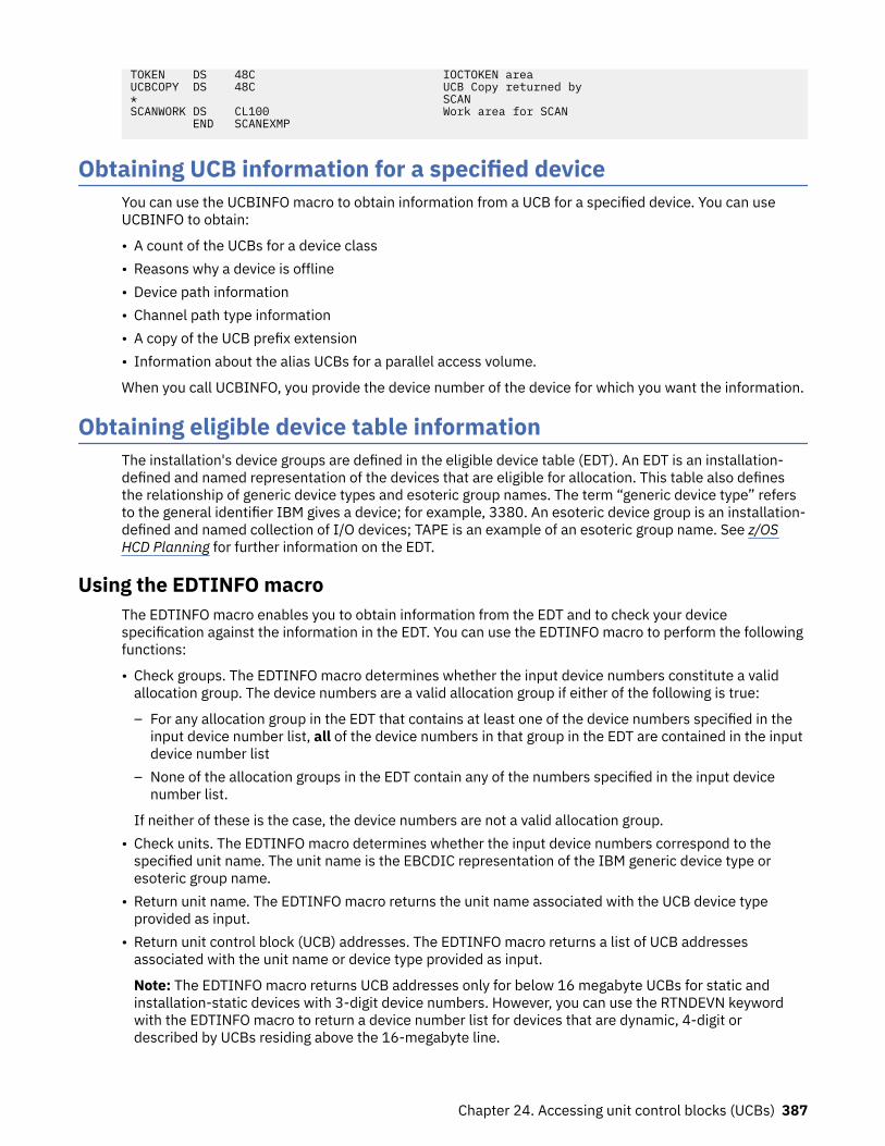
TOKEN DS 48C IOCTOKEN areaUCBCOPY DS 48C UCB Copy returned by* SCANSCANWORK DS CL100 Work area for SCAN END SCANEXMP
Obtaining UCB information for a specified deviceYou can use the UCBINFO macro to obtain information from a UCB for a specified device. You can useUCBINFO to obtain:
• A count of the UCBs for a device class• Reasons why a device is offline• Device path information• Channel path type information• A copy of the UCB prefix extension• Information about the alias UCBs for a parallel access volume.
When you call UCBINFO, you provide the device number of the device for which you want the information.
Obtaining eligible device table informationThe installation's device groups are defined in the eligible device table (EDT). An EDT is an installation-defined and named representation of the devices that are eligible for allocation. This table also definesthe relationship of generic device types and esoteric group names. The term “generic device type” refersto the general identifier IBM gives a device; for example, 3380. An esoteric device group is an installation-defined and named collection of I/O devices; TAPE is an example of an esoteric group name. See z/OSHCD Planning for further information on the EDT.
Using the EDTINFO macroThe EDTINFO macro enables you to obtain information from the EDT and to check your devicespecification against the information in the EDT. You can use the EDTINFO macro to perform the followingfunctions:
• Check groups. The EDTINFO macro determines whether the input device numbers constitute a validallocation group. The device numbers are a valid allocation group if either of the following is true:
– For any allocation group in the EDT that contains at least one of the device numbers specified in theinput device number list, all of the device numbers in that group in the EDT are contained in the inputdevice number list
– None of the allocation groups in the EDT contain any of the numbers specified in the input devicenumber list.
If neither of these is the case, the device numbers are not a valid allocation group.• Check units. The EDTINFO macro determines whether the input device numbers correspond to thespecified unit name. The unit name is the EBCDIC representation of the IBM generic device type oresoteric group name.
• Return unit name. The EDTINFO macro returns the unit name associated with the UCB device typeprovided as input.
• Return unit control block (UCB) addresses. The EDTINFO macro returns a list of UCB addressesassociated with the unit name or device type provided as input.
Note: The EDTINFO macro returns UCB addresses only for below 16 megabyte UCBs for static andinstallation-static devices with 3-digit device numbers. However, you can use the RTNDEVN keywordwith the EDTINFO macro to return a device number list for devices that are dynamic, 4-digit ordescribed by UCBs residing above the 16-megabyte line.
Chapter 24. Accessing unit control blocks (UCBs) 387

The UCBINFO macro can then be used to obtain device number information for a specific devicenumber.
If your program is authorized, running in supervisor state or with a program key mask of 0-7, you canuse the UCBLOOK macro to the obtain the actual UCB address from a given device number. See, z/OSMVS Programming: Authorized Assembler Services Reference SET-WTO, and z/OS MVS Programming:Authorized Assembler Services Guide for the UCBLOOK macro.
• Return group ID. The EDTINFO macro returns the allocation group ID corresponding to each UCBaddress specified as input.
• Return attributes. The EDTINFO macro returns general information about the unit name or device typespecified as input.
• Return unit names for a device class. The EDTINFO macro returns a list of generic device types oresoteric group names associated with the device class specified as input.
• Return UCB device number list. The EDTINFO macro returns the UCB device number list associated withthe unit name or UCB device type specified as input. You can also specify that the following be includedin the list:
– Devices defined to the system as dynamic– Devices defined with 4-digit device numbers– Devices with UCBs defined above 16 megabytes
• Return maximum eligible device type. The EDTINFO macro returns the maximum eligible device type(for the allocation and cataloging of a data set) associated with the unit name or device type, recordingmode, and density provided as input. The maximum eligible device type is the tape device type thatcontains the greatest number of eligible devices compatible with the specified recording mode anddensity.
388 z/OS: z/OS MVS Assembler Services Guide

Chapter 25. Setting up and using an internal reader
The internal reader is a software substitute for a card punch and a card reader, a tape drive, or a TSO/Eterminal. Instead of entering a job into the system (through JES) on punched cards, or through tape, youcan use the output of one job or step as the input to another job, which JES will process directly.
The internal reader facility is useful for several kinds of applications:
• You can use it to generate another job or a series of jobs from an already-executing job. An onlineapplication program may submit another job to produce a report, for example, so it does not have to doit itself.
• A job that produces a series of jobs can put its output to an internal reader for immediate execution. Forexample, a job that updates data bases and starts other applications based upon some inputparameters or real-time events, can use the internal reader for its output.
• The operator can start utility programs to read jobs from disk or tape files and submit them to thesystem. The IBM-supplied procedure ‘RDR’ is an example of a program that does this (see z/OS JES2Initialization and Tuning Guide).
• The operating system itself uses internal readers for submitting the JCL to start up started tasks orTSO/E logons.
Following is a discussion of the batch job internal reader, which is the facility you can use to submit a jobfrom within another job.
The process of setting up and using an internal reader involves five tasks:
• Creating and allocating a data set• Opening the data set• Putting records into the data set• Closing/deallocating the data set• Passing the data set/records to the job entry subsystem for processing
Started tasks that run under the MSTR subsystem have the ability to set up an internal reader. Toaccomplish this they must first successfully invoke the Request Job ID SSI call, and then performallocation. For more information on the Request Job ID call (SSI function code 20), see z/OS MVS Usingthe Subsystem Interface.
Allocating the internal reader data setYou can allocate an internal reader data set, in any address space, either with JCL or dynamically, asfollows:
• Define the data set in the JCL for a job:
//JOBJCL DD SYSOUT=(A,INTRDR)
Note:
1. “INTRDR” is an IBM-reserved name identifying the internal reader as the program to process thisdata set after it is created and written to.
2. The SYSOUT class on this DD statement becomes the message class for the submitted job unlessyou specify MSGCLASS on the JOB statement.
• Use the following dynamic allocation text unit keys to dynamically allocate an internal reader dataset:
– DALSYSOU — define the SYSOUT data set and its class.– DALSPGNM — specify the SYSOUT program name (INTRDR).
© Copyright IBM Corp. 1988, 2020 389

– DALCLOSE — request that INTRDR be deallocated at close.– DALRTDDN — request the return of the ddname assigned by dynamic allocation.– DALLRECL — specify the record length of any instream data set.– DALRECFM — specify the record format of any instream data set.
Note: DALCLOSE, DALRTDDN, DALLRECL and DALRECFM are optional dynamic allocation text unit keys.
For the format details of dynamic allocation text unit keys, see z/OS MVS Programming: AuthorizedAssembler Services Guide.
Note:
1. An INTRDR data set can contain any number of jobs.2. The output destination of the INTRDR data set becomes the default print/punch routing of all jobs
contained within it.3. INTRDR data sets contain sequential, fixed-length, or variable-length records. Instream data records
can be up to 254 bytes long. Note, however, that JCL images in the data sets must be exactly 80 byteslong.
Opening the internal reader data setYou can write to an internal reader using BSAM or QSAM or an ACB interface. With BSAM or QSAM, youcode DSORG=PS in the DCB. There is no advantage to specifying multiple buffers. The most efficientnumber of QSAM buffers (BUFNO in the DCB) is 1. You can use any of these interfaces in 24-bit or 31-bitaddressing mode. If you call in 31-bit mode, the ACB can be above the 16 MB line.
The DCB macro requires that you code the DDNAME keyword. If you code DALRTDDN on the dynamicallocation call, it means that you are requesting dynamic allocation to return the new DD name. If you dothis, you might choose to code a dummy DD name on the DCB or ACB macro. For example, you might codeDDNAME=*.
If you code DALRTDDN, move the returned DDNAME from the DALRTDDN text unit to the DCB or ACBbefore issuing the OPEN macro. The offset to the DDNAME field in the DCB is the same as the offset in theACB. You can use the DCBD mapping macro for either one and copy the DD name to the DCBDDNAM field.For information on using the OPEN, DCB, ACB, and DCBD macros, see z/OS DFSMS Macro Instructions forData Sets.
Opening the INTRDR data set identifies it to the JES and prepares it to receive records.
Opening an internal reader that is already open has no effect. Multiple tasks cannot have the sameinternal reader open at the same time.
Sending job output to the internal readerCode a WRITE (BSAM), PUT (QSAM), or PUT(ACB interface) macro to send records to the internal reader.You code the PUT macro differently for QSAM and for the ACB interface. See the VSAM documentation forhow to code PUT for the ACB interface.
Obtaining a job identifierIf you want to obtain the job identifier for a job, you must use an ENDREQ macro. see z/OS DFSMS MacroInstructions for Data Sets.
Issue an ENDREQ macro after writing a complete job to the internal reader. The job identifier is returnedin the RPLRBAR field of the request parameter list (RPL). See z/OS JES2 Commands or z/OS JES3Commands for details about the job identifier.
RPLRBAR is an 8-byte field. The first 3 bytes, xxx, are the characters JOB, TSU or STC. The remaining 5bytes, nnnnn, represent the five digits of the job number. See z/OS JES2 Initialization and Tuning Guide orz/OS JES3 Initialization and Tuning Guide for more information.
390 z/OS: z/OS MVS Assembler Services Guide

If you submit JCL, and JES does not recognize it as a job, RPLRBAR contains blanks or a job id from anearlier job submitted through the internal reader.
Note that the RPL cannot have records longer than 80 bytes. Specify the following options on the RPLmacro when creating an RPL:
OPTCD=(ADR,SEQ,SYN,NUP),RECLEN=80
Where:ADR
Specifies addressed data processing with no index references.SEQ
Specifies sequential processing.SYN
Specifies a synchronous request and that control should be returned after completion of the request.NUP
Specifies non-update mode (records retrieved are not updated or deleted).RECLEN=80
Specifies that the submitted JCL records are 80 bytes.
Note that you must issue a CLOSE macro after the last ENDREQ.
The format of job numbers being displayed as part of command responses or messages can changedepending on whether JES2 is set up to support greater than 65K jobs. When job numbers are potentiallygreater than 99,999, the format for job numbers is as follows: if the maximum allowed job number (highvalue of the JOBDEF RANGE= statement) is above 99,999, the job number format is J0nnnnnn. Thisformat is used unless the job number range is decreased below 100,000. Similarly, STCnnnnn becomesS0nnnnnn and TSUnnnnn becomes T0nnnnnn.
Note: If you use the PUT macro with the ACB interface to send the job output to the internal reader,allocate the RPL below the 16 MB line or a system abend X'36F' might occur in certain environments,such as JES3 levels earlier than z/OS V1R13 (HJS7780). Starting with z/OS V1R13, JES3 supportsallocating the RPL above the line.
Closing the internal reader data setWhile your program is writing records to the internal reader data set, the internal reader facility is writingthem into a buffer in your address space. Issue the CLOSE macro to close the internal reader data set, andto send the contents of the buffer to JES.
Filling the buffer in your address space sends the records to the JES for processing. JES considers aclosed data set to be a completed job stream and treats it as input. You can also send an internal readerdata set to the JES for processing by coding one of the following:
1. Code /*EOF as the last record in the job.
This control statement delimits the current job and makes it eligible for immediate processing by theJES2 input service. The internal reader data set remains open.
2. Code /*DEL as the last record in the job.
This control statement cancels the job, and requests the output from the job. The job is immediatelyscheduled for output processing. The output will consist of any JCL submitted so far, followed by amessage indicating that the job has been deleted before execution.
3. Code /*PURGE as the last record in the job.
This control statement is used only by JES2 internal readers. It cancels the current job and schedulesit for purge processing; no output is generated for the job.
4. Code /*SCAN as the last record in the job.
Chapter 25. Setting up and using an internal reader 391

This statement also applies only to JES2 internal readers. It requests that the current job be scannedfor JCL errors, but not executed.
You can put several groups of output records into the internal reader data set simply by starting eachgroup with another JCL JOB statement. The following example illustrates this.
//JOBA JOB D58ELM1,MORRIS//GENER EXEC PGM=IEBGENER//SYSIN DD DUMMY//SYSPRINT DD SYSOUT=A,DEST=2NDFLOOR//SYSUT2 DD SYSOUT=(M,INTRDR)//SYSUT1 DD DATA//JOBB JOB D58ELM1,MORRIS,MSGLEVEL=(1,1)//REPORT1 EXEC PGM=SUMMARY//OUTPUT DD SYSOUT=*//INPUT DD DSN=REPORTA,DISP=OLD//JOBC JOB D58ELM1,MORRIS,MSGLEVEL=(1,1)//REPORT2 EXEC PGM=SUMMARY//OUTPUT DD SYSOUT=A,DEST=3RDFLOOR//INPUT DD DSN=REPORTB,DISP=OLD/*EOF
In the preceding example, the IBM-supplied utility program IEBGENER is executed by job A. It reads fromSYSUT1, and submits to the internal reader, jobs B and C, which are report-producing programs. Note thatthe message class for jobs B and C will be M, the SYSOUT class on the internal reader DD statement. Also,the OUTPUT data set from job B, because it specifies “*” (defaulting to the job's message class), will beclass M.
The /*EOF control statement following the JCL indicates that the preceding jobs can be sent immediatelyto the job entry subsystem for input processing. Coding the CLOSE macro would have the same effect.
See z/OS JES2 Initialization and Tuning Guide or z/OS JES3 Initialization and Tuning Guide for moreinformation about setting up and using internal readers.
392 z/OS: z/OS MVS Assembler Services Guide

Chapter 26. Using the symbol substitution service
The ASASYMBM and ASASYMBF services substitute text for symbols in character strings. This chapterexplains how to explicitly call ASASYMBM or ASASYMBF to substitute text for symbols that you specify inapplication and vendor programs. It:
• Describes what symbols are• Lists the symbols that the system provides• Describes how to call ASASYMBM or ASASYMBF to substitute text for symbols.
Note: The system automatically substitutes text for symbols in dynamic allocations, parmlib members,system commands, and job control language (JCL). The system does not provide automatic support forother interfaces, such as application and vendor programs. Those interfaces must call ASASYMBM orASASYMBF to perform symbolic substitution.
What are symbols?Symbols are elements that allow the system to use the same source code for two or more uniqueinstances of the same program. Symbols represent the variable information in a program. The programcalls the ASASYMBM or ASASYMBF macro to substitute text for the symbols.
For example, suppose you define the following data set name, with the &TCASEID. symbol as the low-level qualifier:
TEST.&TCASEID.
Then suppose that two different instances of a program each call ASASYMBM or ASASYMBF, one withTEST001 as the substitution text for &TCASEID and the other with TEST002 as the substitution text. Theresulting data set names are:
TEST.TEST001 TEST.TEST002
Notice that one data set definition produces two unique instances of data sets to be used in the programs.
Types of symbolsThere are two types of symbols that you can specify in application or vendor programs:
• System symbols are defined to the system at initialization. Your installation specifies substitution textsfor system symbols or accepts their default values. When a program calls ASASYMBM or ASASYMBF, itcan accept the installation-defined substitution texts or override them. There are two types of systemsymbols:
– Static system symbols have substitution texts that are defined at system initialization and remainfixed for the life of an IPL. Static system symbols represent fixed values such as system names andsysplex names.
The DISPLAY SYMBOLS command displays the static system symbols and associated substitutiontexts that are currently in effect. See z/OS MVS System Commands for details about DISPLAYSYMBOLS.
– Dynamic system symbols have substitution texts that can change at any point in an IPL. Theyrepresent values that can change often, such as dates and times. A set of dynamic system symbols isdefined to the system; your installation cannot provide additional dynamic system symbols.
See the information on using system symbols in z/OS MVS Initialization and Tuning Reference for lists ofdynamic and static system symbols.
© Copyright IBM Corp. 1988, 2020 393

• User symbols are symbols that a caller defines on a call to ASASYMBM or ASASYMBF. They are validonly for the specific call. The caller specifies the names and substitution texts for user symbols in asymbol table. If the names of user symbols are the same as the names of system symbols, thesubstitution texts for the user symbols override the substitution texts for the system symbols.
The ASASYMBM service supports the use of sub-strings for both system and user symbols as described inz/OS MVS Initialization and Tuning Reference in section Using substrings of system symbols.
If your program accepts the substitution texts for the installation-defined system symbols, there is noneed to specify those system symbols in the symbol table that you provide to ASASYMBM or ASASYMBF;substitution for those system symbols is performed automatically. However, if your program wants tooverride the installation-defined substitution texts for system symbols, you must specify those systemsymbols in the symbol table. The symbol table is the only place where you can specify user symbols.
Examples of user symbolsLike system symbols, user symbols can represent any type of variable information in a program. Whenplanning to define user symbols, you should first determine if the system symbols provided by the system,and their associated substitution texts, meet your needs. Define user symbols only if you need additionalvalues.
Suppose you are writing a program that is to access several data sets each time it runs. The user is toprovide the name of the specific data set to be used.
Your first step is to create a pattern, or "skeleton", for the data set name. You decide to use the name ofthe system on which the program runs as a high-level qualifier, and the name of the data set that the userprovides as a low-level qualifier.
You decide to use the &SYSNAME system symbol to identify the system on which the program runs.Because &SYSNAME is already defined to the system, and you do not want to override its substitutiontext, you do not need to provide it to ASASYMBM or ASASYMBF. Because the system does not define asymbol to identify the input from the user, you provide the following user symbol to ASASYMBM orASASYMBF:
TESTDATA DC C'&&DATAID.' Define the symbol &DATAID
You begin by specifying, in your program, references to three data sets:
&SYSNAME..&DATAID..DS1 &SYSNAME..&DATAID..DS2 &SYSNAME..&DATAID..DS3
You then specify that the user is to provide, as input to the program, the substitution text for the &DATAIDuser symbol. For example:
EXEC PGM=MYPGM,PARM='DATA1'
Your program provides, as input to ASASYMBM or ASASYMBF, a symbol table that contains the &DATAIDuser symbol, with the substitution text that the user provided as input to the program:
DATAIDSUBTEXT DC C'DATA1' Substitution text for &DATAID
To determine the data set name to be used, your program also provides to ASASYMBM or ASASYMBF thepattern for the data set name, including the symbols for which substitution is to occur. For example:
SYS1.&SYSNAME..&DATAID..DS1 SYS1.&SYSNAME..&DATAID..DS2 SYS1.&SYSNAME..&DATAID..DS3
The data set names resolve to the following names after symbolic substitution:
SYS1.DATA1.DS1 SYS1.DATA1.DS2 SYS1.DATA1.DS3
394 z/OS: z/OS MVS Assembler Services Guide

“Calling the ASASYMBM or ASASYMBF service” on page 395 explains how to call ASASYMBM orASASYMBF to perform the substitution described in the example.
Calling the ASASYMBM or ASASYMBF serviceA call to ASASYMBM/ASASYMBF:
1. Defines, to the system, the system symbols that ASASYMBM/ASASYMBF is to use.2. Defines, to the system, user symbols that are specified in the symbol table (as described later).3. Substitutes values for the symbols in the symbol table, based on an input character string (pattern).4. Places the results of the substitution in an output buffer that the caller specifies.5. Places the length of the output buffer in a field.6. Provides a return code to the calling program.
You must include the ASASYMBP mapping macro to build the user parameter area (SYMBP) forASASYMBM/ASASYMBF. The information describes how to set up ASASYMBP to enable the desiredfunctions.
The two services differ as follows:
• ASASYMBM obtains and releases dynamic storage for use by the symbol substitution service. Input ismapped using either the SYMBP or SYMBFP DSECT of the ASASYMBP mapping macro.
• ASASYMBF allows callers to pass in a 1024 byte work area for the symbol substitution service to use asdynamic storage, so that there is no need to obtain (and release) storage for that purpose. ForASASYMBF, input is mapped by the SYMBFP DSECT of the ASASYMBP mapping macro.
Because the SYMBP and SYMBFP DSECTs are much the same, except for different field names and oneextra field (SymbfpWorkareaAddr) in SYMBFP, you can build the SYMBFP area in advance and then decideat runtime whether to call or LINK to ASASYMBM or ASASYMBF.
Setting up the ASASYMBP mapping macroBefore calling ASASYMBM/ASASYMBF to substitute text for a symbol, the caller must provide the symbolpattern and its length, an output buffer and its length, and an area in which to place the return code fromASASYMBM/ASASYMBF. The caller can optionally provide a symbol table and a time stamp.
The caller must code the following fields in the ASASYMBP mapping macro:Field
DescriptionSYMBPPATTERN@
Specifies the address of the input character string (pattern) that contains symbols to be resolved.SYMBPPATTERNLENGTH
Specifies the length of the input pattern specified in the PATTERN@ field.SYMBPTARGET@
Specifies the address of the buffer that is to contain the output from ASASYMBM/ASASYMBF (theresults of the symbolic substitution).
SYMBPTARGETLENGTH@Specifies the address of a fullword that:
• On input, contains the length of the output buffer specified in the TARGET@ field• On output, contains the length of the substituted text within the output buffer.
SYMBPRETURNCODE@Specifies the address of a fullword that is to contain the return code from ASASYMBM/ASASYMBF.
Before calling ASASYMBM/ASASYMBF, you can optionally code the following fields in the ASASYMBPmapping macro:
Chapter 26. Using the symbol substitution service 395

FieldDescription
SYMBPSYMBOLTABLE@Specifies the address of a symbol table mapped by the SYMBT or SYMBT1 DSECT. Specify an addressin this field if you want to do one or both of the following:
• Provide symbols in addition to the system symbols that are defined to the system, or override thesystem symbols that are defined to the system.
• Use additional functions of ASASYMBM/ASASYMBF, which are described in “Providing a symboltable to ASASYMBM / ASASYMBF” on page 396.
Otherwise, specify an address of 0 in this field.
SYMBPTIMESTAMP@Specifies the address of an eight-character area that contains the time stamp to be used. The formatof the time stamp is the same as the format of the system time of day clock (in other words, theformat of the value returned by the STCK instruction). Specify an address of zero to have the systemuse the current time stamp when substituting for system symbols that relate to the time or date. Bydefault, the input time stamp is Greenwich Mean Time. Use the TIMESTAMPISLOCAL orTIMESTAMPISSTCK bits to indicate that the input time stamp is local, or obtained from the systemtime of day clock.
After the call to ASASYMBM/ASASYMBF, the caller can examine the following:
• The fullword pointed to by the SYMBPRETURNCODE@ field• The fullword pointed to by the SYMBPTARGETLENGTH@ field• The area pointed to by the SYMBPTARGET@ field.
Providing a symbol table to ASASYMBM / ASASYMBFA program that calls ASASYMBM/ASASYMBF can optionally provide user symbols and their associatedsubstitution texts in a symbol table. The SYMBPSYMBOLTABLE@ field, in the user parameter area of theASASYMBP mapping macro, specifies the address of a symbol table, which is mapped by either DSECTSYMBT or SYMBT1. DSECT SYMBT is the default; turn on bit Symbt1Symbt1 to indicate that you are usingthe SYMBT1 DSECT.
Note that only the first two bytes of the SYMBT1 DSECT are compatible with SYMBT DSECT.
When you use a SYMBT1 DSECT, symbols provided within a user-built symbol table are required to beginwith an ampersand and end with a period and all symbol names must be less than 256 bytes (except foran input symbol area returned by the IEFSJSYM macro; see Input symbol area returned by IEFSJSYM).
The SYMBT1 DSECT supports the following functions beyond those provided by SYMBT:Multiple symbol tables:
In addition to the system symbol table, you can specify multiple user-provided symbol tables with onecall to ASASYMBM/ASASYMBF. Specify user-provided symbol tables in field Symbt1NextSymbtAddr.This address can point to a symbol table mapped by either the SYMBT or SYMBT1 DSECT, as indicatedby bit Symbt1Symbt1.
• If a SYMBT DSECT is found, then this is the last table in the queue.• If a SYMBT1 DSECT is found, then a zero in Symbt1NextSymbtAddr indicates that this is the last
table in the queue. When you specify multiple user-provided symbol tables, many of the options thatmay be specified within an individual SYMBT1/SYMBT DSECT are honored within the first SYMBT1only. These are all identified within the commentary for the SYMBT1 DSECT.
Continue after full:When the target buffer is not long enough to contain the full result, the system continues processing inorder to determine how long the target buffer must be to contain the full result. The system outputs inregister 0 the length required to fit the full result.
396 z/OS: z/OS MVS Assembler Services Guide

Preserve alignment:Text position is less sensitive to the length of the symbol's substitution text. If there is a chain ofSYMBT1s, this function is honored only for the first SYMBT1 of the chain. This function also impliesthe continue after full function.
Uncompressed double ampersand:Double ampersands are not compressed into one ampersand. If there is a chain of SYMBT1s, this ishonored for the first SYMBT1 of that chain only. This function also implies the continue after fullfunction.
Input symbol area returned by IEFSJSYM:The input symbol area is returned by the IEFSJSYM service, which extracts JCL symbols and theirvalues. This area is mapped by IEFSJSYD. This function also implies the continue after full function.
Notes:
• The input symbol area returned by IEFSJYSM is not in the same format as the symbol area normallyrequired by ASASYMBM/ASASYMBF using a SYMBT DSECT.
• The area returned by the IEFSJSYM macro is not considered a user-built symbol table and symbolsin this area do not begin with an ampersand and end with a period.
Setting up the symbol tableWhen you provide a symbol table to the ASASYMBM/ASASYMBF service (that is, when you specify a non-zero address in the SYMBPSYMBOLTABLE@ field), you can specify either DSECT SYMBT or SYMBT1 withbit Symbt1Symbt1 and code the following fields in the ASASYMBP mapping macro:
FieldDescription
SYMBTNUMBEROFSYMBOLSSpecifies the number of entries in the symbol table. The number can be zero.
SYMBTTABLEENTRIESSpecifies the beginning of the entries in the symbol table. If the SYMBTINDIRECTSYMBOLAREA bit isoff, the symbol table entries must be contiguous to the header, beginning at this field. Otherwise,place the SYMBTESYMBOLAREAADDR field in this field; SYMBTESYMBOLAREAADDR must point to anarea that contains the symbol table entries. SYMBTESYMBOLAREAADDR is a field in the SYMBTEstructure; for details about the ASASYMBP mapping, see z/OS MVS Data Areas in the z/OS Internetlibrary (www.ibm.com/servers/resourcelink/svc00100.nsf/pages/zosInternetLibrary).
SYMBTESpecifies an entry in the symbol table. Code one symbol table entry (SYMBTE) for each symbol in thesymbol table. The number of entries is specified in the SYMBTNUMBEROFSYMBOLS field. If theSYMBTINDIRECTSYMBOLAREA bit is off, the symbol table entries must be contiguous to the header,beginning at the SYMBTTABLEENTRIES field. Otherwise, the symbol table entries begin at the areapointed to by the SYMBTESYMBOLAREAADDR field.
Each symbol table entry (SYMBTE) must set the following fields:
• SYMBTESYMBOLPTR, when the SYMBTPTRSAREOFFSETS flag is off; it specifies the address of thearea that contains the name of the symbol
• SYMBTESYMBOFFSET, when the SYMBTPTRSAREOFFSETS flag is on; it specifies the offset to thesymbol from the beginning of the symbol area; you must also set up the area pointed to by the offset
• SYMBTESYMBOLLENGTH, which specifies the length of the symbol• SYMBTESUBTEXTPTR, when the SYMBTPTRSAREOFFSETS flag is off; it specifies the address of the
area that contains the substitution text for the symbol• SYMBTESUBTEXTOFFSET, when the SYMBTPTRSAREOFFSETS flag is on; it specifies the offset to
the substitution text from the beginning of the symbol area; you must also set up the area pointed toby the offset
• SYMBTESUBTEXTLENGTH, which specifies the length of the substitution text.
Chapter 26. Using the symbol substitution service 397

If you specify an address in the SYMBPSYMBOLTABLE@ field, you must also provide a symbol tableheader (SYMBTHEADER). Optionally, set one or more of the flags in the symbol table header to indicatethat ASASYMBM is to perform additional functions.
Note: The field and bit names in the following list are all prefixed by the characters SYMBT in theASASYMBP mapping macro. The SYMBT prefix is not used out of consideration for readability.
FlagFunction
CHECKNULLSUBTEXTSpecifies that ASASYMBM is to return a return code of X'0C' if the substitution text for a symbol is anull string (has a length of zero).
The default is to not check if the substitution text for a symbol is a null string.
INDIRECTSYMBOLAREASpecifies that the symbol area is not contiguous; it is pointed to by the SYMBTESYMBOLAREAADDRfield. For an example of a symbol area that is not contiguous, see Figure 109 on page 400.
The default is that the symbol area is contiguous.
NODEFAULTSYMBOLSSpecifies that ASASYMBM is not to use the default set of system symbols. In other words, ASASYMBMuses only the symbols that are defined in the user-provided symbol table.
When you do not set this flag, ONLYDYNAMICSYMBOLS, or ONLYSTATICSYMBOLS to on, the default isto use both dynamic and static system symbols.
ONLYDYNAMICSYMBOLSSpecifies that ASASYMBM is not to substitute text for the static system symbols.
ONLYSTATICSYMBOLSSpecifies that ASASYMBM is not to substitute text for the dynamic system symbols.
PTRSAREOFFSETSSpecifies that the pointer fields in the symbol table are offsets. The system adds the offset to theaddress of the symbol area to obtain the actual address of the operand.
The default is to indicate that the pointer fields in the symbol table are pointers.
MIXEDCASESYMBOLSSpecifies that the system is to recognize, within an input pattern, symbols that contain:
• All upper-case characters, and• Both upper-case and lower-case characters.
The default is to recognize symbols that match the symbols in the symbol table.
TIMESTAMPISGMTSpecifies that the input time stamp is Coordinated Universal Time (UTC) or Greenwich Mean Time(GMT). TIMESTAMPISGMT is the default when you provide a time stamp (in the area pointed to bySYMBPTIMESTAMP@) and you do not set this flag, TIMESTAMPISLOCAL, or TIMESTAMPISSTCK to on.
TIMESTAMPISLOCALSpecifies that the input time stamp is local time.
TIMESTAMPISSTCKSpecifies that the input time stamp is obtained from the system time of day (TOD) clock.
WARNNOSUBSpecifies that ASASYMBM is to return a X'10' return code when the system does not perform symbolicsubstitution.
The default is to not return a return code when the system does not perform symbolic substitution.
398 z/OS: z/OS MVS Assembler Services Guide

WARNSUBSTRINGSSpecifies that ASASYMBM is to return a X'04' return code when the system finds a substring error. Seethe information on using symbols in z/OS MVS Initialization and Tuning Reference for informationabout how the system performs symbolic substitution when errors occur in substringing.
The default is to not return a return code when the system finds a substring error.
The following is an example of a symbol table that is contiguous:
Figure 108. Contiguous Symbol Table
The following is an example of a symbol table that is not contiguous:
Chapter 26. Using the symbol substitution service 399

Figure 109. Non-contiguous Symbol Table
Rules for entering symbols in the symbol tableFollow these rules when specifying entries in the symbol table:
1. The names of the symbols must:
• Begin with an ampersand (&)• End with a period (.)• Contain 1-253 additional characters (in other words, you cannot create the symbol "&.").
Note: It is important that all symbols end with a period. If a symbol does not end with a period, syntaxerrors could result.
2. Specify the names of system symbols only if you want to override the installation-defined substitutiontexts for those system symbols. Ask the operator to enter a DISPLAY SYMBOLS command to displaythe system symbols and associated substitution texts that are currently in effect.
3. Do not begin the names of user symbols with the characters &SYS. The &SYS prefix is reserved forsystem symbols; use the &SYS prefix only when overriding substitution texts for system symbols.
4. The length of the substitution text cannot exceed the length of the symbol name plus the ampersand(&) unless the symbol name ends with an underscore, in which case the substitution text can be up to44 characters long.
Except for symbols ending with an underscore, this restriction prevents the flow of characters beyondestablished limits for text entry. For example, assume that the limit for text entry is column 71. If a linethat contains a four-character symbol extends to column 70, a substitution text of greater than sixcharacters would force the text beyond column 71.
When using a symbol that ends with an underscore, note that you must handle unintended results,such as truncation with no warning, which might occur if the resulting substitution causes flow ofcharacters to extend beyond an intended limit. For example, in a parmlib member, make sure that theresulting substitution would not cause characters to extend beyond column 71. While programs arenot expected to accommodate such line overflow, you can code your program to handle it.
400 z/OS: z/OS MVS Assembler Services Guide

IBM provides ISPF exec ASASYMUN to help you locate data that might encounter unexpected results ifsymbol names have underscores. ASASYMUN scans a PDS or PDSE looking for situations where asymbol name containing an underscore could cause different results than expected. For example, itlooks for a symbol (an ampersand followed by other characters) followed immediately by anunderscore with no delimiting period. You should change lines like these to add a period before theunderscore to delimit the symbol. The ASASYMUN exec works on any z/OS release but is only shippedin the z/OS V2R2 release or later.
The syntax of ASASYMUN is as follows:
EXEC execdsn(ASASYMUN) 'scandsn'
Where:execdsn
is the cataloged data set containing the ASASYMUN exec. Use execdsn(ASASYMUN) if the data setname is fully qualified. You can use alternate forms of execdsn(ASASYMUN) if the data set is in theSYSEXEC or SYSPROC concatenation of the user. For example, you might be able to specify just'(ASASYMUN)'.
scandsnis the PDS or PDSE you want to scan. Specify a data set contain statements subject to symbolsubstitution, like JCL or parmlib statements. If the data set name is fully-qualified, double thequotes around the name in addition to the single quotes surrounding the parameter. For example,specify '''fully.qual.dsn''' for a fully qualified data set.
Using symbols in programsYour program can call ASASYMBM to substitute text for the symbols that are specified in the program. Thefollowing examples show how to call ASASYMBM in various situations.
Example 1
OperationSet up the area that is to contain the substitution text. The caller does not provide a symbol table or timestamp.
LA 3,MYSYMBP USING SYMBP,3 XC SYMBP(SYMBP_LEN),SYMBP Initialize to zero LA 4,PATTERN Address of pattern ST 4,SYMBPPATTERN@ Save in SYMBP area LA 4,L'PATTERN Length of pattern ST 4,SYMBPPATTERNLENGTH Save in SYMBP area LA 4,TARGET Address of target ST 4,SYMBPTARGET@ Save in SYMBP area MVC TARGETLENGTH,=A(L'TARGET) Set length of target LA 4,TARGETLENGTH Address of target length ST 4,SYMBPTARGETLENGTH@ Save in SYMBP area** Because the caller did not provide a symbol table, we know that* we are using only the system symbols provided by MVS. Since we have* initialized the entire SYMBP area to 0, we do not have to* set up the SYMBPSYMBOLTABLE@ field.** Because the caller did not provide a timestamp, and because we* have initialized the entire SYMBP area to 0, we do not have to* set up the SYMBPTIMESTAMP@ field.* LA 4,RETURNCODE Address of return code ST 4,SYMBPRETURNCODE@ Save in SYMBP area DROP 3⋮** Note that to avoid the assembler substituting* for &SYSNAME, &YYMMDD, &HHMMSS, two ampersands are specified.* The resulting pattern, then, is actually* USERID.&SYSNAME..D&YYMMDD..T&HHMMSS
Chapter 26. Using the symbol substitution service 401
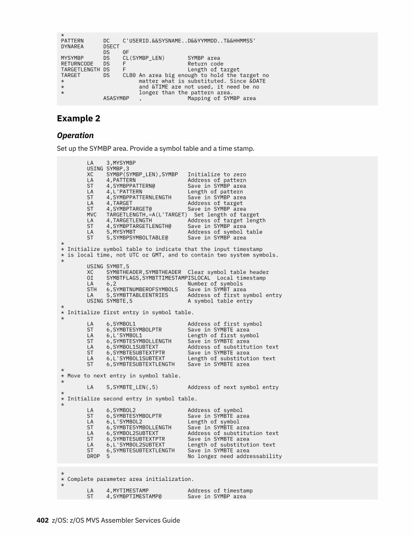
*PATTERN DC C'USERID.&&SYSNAME..D&&YYMMDD..T&&HHMMSS'DYNAREA DSECT DS 0FMYSYMBP DS CL(SYMBP_LEN) SYMBP areaRETURNCODE DS F Return codeTARGETLENGTH DS F Length of targetTARGET DS CL80 An area big enough to hold the target no* matter what is substituted. Since &DATE* and &TIME are not used, it need be no* longer than the pattern area. ASASYMBP , Mapping of SYMBP area
Example 2
OperationSet up the SYMBP area. Provide a symbol table and a time stamp.
LA 3,MYSYMBP USING SYMBP,3 XC SYMBP(SYMBP_LEN),SYMBP Initialize to zero LA 4,PATTERN Address of pattern ST 4,SYMBPPATTERN@ Save in SYMBP area LA 4,L'PATTERN Length of pattern ST 4,SYMBPPATTERNLENGTH Save in SYMBP area LA 4,TARGET Address of target ST 4,SYMBPTARGET@ Save in SYMBP area MVC TARGETLENGTH,=A(L'TARGET) Set length of target LA 4,TARGETLENGTH Address of target length ST 4,SYMBPTARGETLENGTH@ Save in SYMBP area LA 5,MYSYMBT Address of symbol table ST 5,SYMBPSYMBOLTABLE@ Save in SYMBP area** Initialize symbol table to indicate that the input timestamp* is local time, not UTC or GMT, and to contain two system symbols.* USING SYMBT,5 XC SYMBTHEADER,SYMBTHEADER Clear symbol table header OI SYMBTFLAGS,SYMBTTIMESTAMPISLOCAL Local timestamp LA 6,2 Number of symbols STH 6,SYMBTNUMBEROFSYMBOLS Save in SYMBT area LA 5,SYMBTTABLEENTRIES Address of first symbol entry USING SYMBTE,5 A symbol table entry** Initialize first entry in symbol table.* LA 6,SYMBOL1 Address of first symbol ST 6,SYMBTESYMBOLPTR Save in SYMBTE area LA 6,L'SYMBOL1 Length of first symbol ST 6,SYMBTESYMBOLLENGTH Save in SYMBTE area LA 6,SYMBOL1SUBTEXT Address of substitution text ST 6,SYMBTESUBTEXTPTR Save in SYMBTE area LA 6,L'SYMBOL1SUBTEXT Length of substitution text ST 6,SYMBTESUBTEXTLENGTH Save in SYMBTE area** Move to next entry in symbol table.* LA 5,SYMBTE_LEN(,5) Address of next symbol entry** Initialize second entry in symbol table.* LA 6,SYMBOL2 Address of symbol ST 6,SYMBTESYMBOLPTR Save in SYMBTE area LA 6,L'SYMBOL2 Length of symbol ST 6,SYMBTESYMBOLLENGTH Save in SYMBTE area LA 6,SYMBOL2SUBTEXT Address of substitution text ST 6,SYMBTESUBTEXTPTR Save in SYMBTE area LA 6,L'SYMBOL2SUBTEXT Length of substitution text ST 6,SYMBTESUBTEXTLENGTH Save in SYMBTE area DROP 5 No longer need addressability
** Complete parameter area initialization.* LA 4,MYTIMESTAMP Address of timestamp ST 4,SYMBPTIMESTAMP@ Save in SYMBP area
402 z/OS: z/OS MVS Assembler Services Guide

LA 4,RETURNCODE Address of return code ST 4,SYMBPRETURNCODE@ Save in SYMBP area DROP 3 No longer need addressability⋮** Note that in order to avoid the assembler's substituting* for &YYMMDD, &HHMMSS, &S1, &S2, two ampersands are specified.* The resulting pattern, then, is actually* USERID.&YYMMDD..&S1..&S2* Similarly, the resulting symbol names are* &S1; and &S2;*PATTERN DC C'USERID.D&&YYMMDD..T&&HHMMSS..&&S1..&&S2'SYMBOL1 DC C'&&S1.' First symbol is &S1SYMBOL1SUBTEXT DC C'S1V' Substitution text for &S1SYMBOL2 DC C'&&S2.' Second symbol is &S2SYMBOL2SUBTEXT DC C'S2V' Substitution text for &S2* Note that the substitution text values above are no longer than* the symbol names (counting the "&" but not the "."). This* helps to ensure that the substituted length is not greater* than the pre-substitution length.*DYNAREA DSECT DS 0FMYSYMBP DS CL(SYMBP_LEN) SYMBP area DS 0FMYSYMBT DS CL(SYMBT_LEN+2*SYMBTE_LEN) Symbol table with* room for two symbol entriesMYTIMESTAMP DS CL8 Time stamp that was set previously* Assume it represents local timeRETURNCODE DS F Return codeTARGETLENGTH DS F Input/Output Target LengthTARGET DS CL80 An area big enough to hold the target no* matter what is substituted ASASYMBP , Mapping of SYMBP, SYMBT, SYMBTE
Example 3
OperationUse the LINK macro to invoke the ASASYMBM service:
* Set up MYSYMBP as in previous examples.⋮ LINK EP=ASASYMBM,MF=(E,MYSYMBP)⋮DYNAREA DSECT DS 0FMYSYMBP DS CL(SYMBP_LEN) SYMBP area ASASYMBP , Mapping of SYMBP area
Example 4
OperationUse the LINKX macro to invoke the ASASYMBM service:
* Set up MYSYMBP as in previous examples.⋮ MVC MYLIST(MYSLIST_LEN),MYSLIST Initialize execute form LINKX EP=ASASYMBM,MF=(E,MYSYMBP),SF=(E,MYLIST) call service⋮MYSLIST LINKX SF=L Initialized list formMYSLIST_LEN EQU *-MYSLIST Length of list formDYNAREA DSECTMYLIST LINKX SF=L List form in dynamic area DS 0FMYSYMBP DS CL(SYMBP_LEN) SYMBP area ASASYMBP , Mapping of SYMBP area
Chapter 26. Using the symbol substitution service 403

404 z/OS: z/OS MVS Assembler Services Guide

Chapter 27. Using system logger services
This chapter covers the information you need to write a system logger application, including the followingtopics:
• “What is system logger?” on page 405• “The system logger configuration” on page 408.• “Overview of system logger services” on page 411.• “IXGINVNT: Managing the LOGR, LOGRY and LOGRZ policies” on page 421.• “IXGCONN: Connecting to and disconnecting from a log stream” on page 426.• “IXGWRITE: Writing to a log stream” on page 433.• “IXGBRWSE: Browsing/reading a log stream” on page 437.• “IXGDELET: Deleting log blocks from a log stream” on page 440.• “IXGIMPRT: Import log blocks” on page 441.• “IXGQUERY: Get information about a log stream or system logger” on page 442.• “IXGOFFLD: Initiate offload to DASD log data sets” on page 446.• “IXGUPDAT: Modify log stream control information” on page 447.• “Setting up the system logger configuration” on page 447.• “Reading data from log streams in data set format” on page 447.• “When things go wrong — Recovery scenarios for system logger” on page 453.
What is system logger?System logger is a set of services that allows an application to write, browse, and delete log data. You canuse system logger services to merge data from multiple instances of an application, including mergingdata from different systems across a sysplex.
For example, suppose you are concurrently running multiple instances of an application in a sysplex, andeach application instance can update a common database. It is important for your installation to maintaina common log of all updates to the database from across the sysplex, so that if the database should bedamaged, it can be restored from the backup copy. You can merge the log data from applications across the sysplex into a log stream, which is simply a collection of data in log blocks residing in the couplingfacility and on DASD (see Figure 110 on page 405).
Figure 110. System Logger Log Stream
© Copyright IBM Corp. 1988, 2020 405

The log streamA log stream is an application specific collection of data that is used as a log. The data is written to andread from the log stream by one or more instances of the application associated with the log stream. A logstream can be used for such purposes as a transaction log, a log for re-creating databases, a recovery log,or other logs needed by applications.
A system logger application can write log data into a log stream, which is simply a collection of data. Datain a log stream spans two kinds of storage:
• Interim storage, where data can be accessed quickly without incurring the overhead of DASD I/O.• DASD log data set storage, where data is hardened for longer term access. When the interim storage
medium for a log stream reaches a user-defined threshold, the log data is offloaded to DASD log datasets.
There are two types of log streams; coupling facility log streams and DASD-only log streams. The maindifference between the two types of log streams is the storage medium system logger uses to hold interimlog data:
• In a coupling facility log stream, interim storage for log data is in coupling facility list structures. See“Coupling facility log stream” on page 406.
• In a DASD-only log stream interim storage for log data is contained in local storage buffers on thesystem. Local storage buffers are data space areas associated with the system logger address space,IXGLOGR. See “DASD-only log stream” on page 407.
Your installation can use just coupling facility log streams, just DASD-only log streams, or a combinationof both types of log streams. The requirements and preparation steps for the two types of log streams aresomewhat different; see “Setting up the system logger configuration” on page 447.
Some key considerations for choosing either coupling facility log steams or DASD-only log streams are:
• The location and concurrent activity of writers and readers to a log stream's log data• The volume of log data written to a log stream.
Coupling Facility log streams are required when:
1. You require more than one concurrent log writer or log reader to the log stream from more than onesystem in the sysplex.
2. You are recording high volumes of log data being to the log stream.
You can use DASD-only log streams when:
1. You require no more than one concurrent log writer or log reader to the log stream from more than onesystem in the sysplex.
2. You are recording low volumes of log data to the log stream.
Note: Since DASD-only log streams always use staging data sets, high volume writers of log data may bethrottled back by the I/O required to record each record sequentially to the log stream's staging data sets.
With z/OS Release 3 and higher, you can also upgrade existing coupling facility log streams to use adifferent coupling facility structure. See “Updating an existing structure-based log stream to anotherstructure” on page 424.
Coupling facility log streamFigure 111 on page 407 shows how a coupling facility log stream spans two levels of storage; the couplingfacility for interim storage and DASD log data sets for more permanent storage. When the coupling facilityspace for the log stream fills, the data is offloaded to DASD log data sets. A coupling facility log streamcan contain data from multiple systems, allowing a system logger application to merge data from systemsacross the sysplex.
406 z/OS: z/OS MVS Assembler Services Guide

Figure 111. Log Stream Data on the Coupling Facility and DASD
When a system logger application writes a log block to a coupling facility log stream, system logger writesit first to a coupling facility list structure. System logger requires that a coupling facility list structure beassociated with each log stream. When the coupling facility structure space allocated for the log streamreaches the installation-defined threshold, system logger moves (offloads) the log blocks from thecoupling facility structure to VSAM linear DASD data sets, so that the coupling facility space for the logstream can be used to hold new log blocks. From a user's point of view, the actual location of the log datain the log stream is transparent.
DASD-only log streamFigure 112 on page 408 shows a DASD-only log stream spanning two levels of storage; local storagebuffers for interim storage, which is then offloaded to DASD log data sets for more permanent storage.
A DASD-only log stream has a single-system scope; only one system at a time can connect to a DASD-onlylog stream. Multiple applications from the same system can, however, simultaneously connect to a DASD-only log stream.
Chapter 27. Using system logger services 407

Figure 112. Log Stream Data in Local Storage Buffers and DASD Log Data Sets
When a system logger application writes a log block to a DASD-only log stream, system logger writes itfirst to the local storage buffers for the system and duplexes it to a DASD staging data set associated withthe log stream. When the staging data set space allocated for the log stream reaches the installation-defined threshold, system logger offloads the log blocks from local storage buffers to VSAM linear DASDdata sets. From a user's point of view, the actual location of the log data in the log stream is transparent.
Both a DASD-only log stream and a coupling facility log stream can have data in multiple DASD log datasets; as a log stream fills log data sets on DASD, system logger automatically allocates new ones for thelog stream.
The system logger configurationThe system logger configuration you use depends on whether or not you use a coupling facility.
Coupling facility log stream configuration: Figure 113 on page 409 shows all the parts involved when asystem logger application writes to a coupling facility log stream. In this example, a system loggerapplication runs on two systems in a sysplex. Both instances of the application write data to the same logstream, TRANSLOG. Each system contains a system logger address space. A system logger applicationuses system logger services to access the system logger capabilities.
When a system logger application writes data to a coupling facility log stream, system logger writes thedata to a coupling facility list structure associated with the log stream. Then, when the coupling facilitystructure fills with data, system logger offloads the data to DASD log data sets.
You can optionally elect to have coupling facility data duplexed to DASD staging data sets for a couplingfacility log stream.
408 z/OS: z/OS MVS Assembler Services Guide

Figure 113. A Complete Coupling Facility Log Stream Configuration
DASD-only log stream configuration: Figure 114 on page 410 shows all the parts involved when asystem logger application writes to a DASD-only log stream. System logger writes the data to the localstorage buffers on the system, duplexing it at the same time to the DASD staging data sets associatedwith the log stream. Then, when the staging data set fills with data, system logger offloads the data toDASD log data sets. Note that where duplexing to DASD staging data sets is an option for a couplingfacility log stream, it is a required automatic part of a DASD-only log stream. A system logger applicationuses system logger services to access the system logger capabilities.
Chapter 27. Using system logger services 409

Figure 114. A DASD-Only Configuration
For general configuration information, see the following references:
• The LOGR, LOGRY, and LOGRZ couple data sets (active system logger policy) in z/OS MVS Setting Up aSysplex
• Log data on the coupling facility in z/OS MVS Setting Up a Sysplex• Log data on DASD log data sets in z/OS MVS Setting Up a Sysplex• Duplexing log data in z/OS MVS Setting Up a Sysplex
The system logger componentThe system logger component resides in its own address space on each system in a sysplex. Some of thecomponent processing will differ, depending on whether a given log stream is a coupling facility logstream or a DASD-only log stream. The system logger component does the following:
• Provides a set of system services that allows a system logger application to use the system loggercomponent. See z/OS MVS Programming: Assembler Services Reference IAR-XCT.
• Maintains information in the active system logger policy about the current use of log streams and ifused, coupling facility list structures.
• For coupling facility log streams, system logger interacts with cross-system extended services (XES) toconnect to and use the coupling facility for system logger applications.
• Obtains local storage buffer space. For a coupling facility log stream, local storage buffers can be usedfor duplexing log data. For a DASD-only log stream, local storage buffers are used as interim storage forlog data before it is offloaded to DASD log data sets.
• Offloads data to DASD log data sets as follows:
For coupling facility log streams, system logger offloads log data from the coupling facility to DASD logdata sets as the coupling facility structure space associated with the log stream reaches theinstallation-defined thresholds.
For DASD-only log streams, system logger offloads log data from the local storage buffers to DASD logdata sets as the DASD staging data set space reaches the installation-defined thresholds.
• Automatically allocates new DASD log data sets for log streams.
410 z/OS: z/OS MVS Assembler Services Guide

• Maintains a backup copy of (duplexes) log data that is in interim storage for recovery. Log data in interimstorage is vulnerable to loss due to system or sysplex failure because it has not yet been hardened toDASD log data sets. System logger duplexes interim storage log data for both coupling facility andDASD-only log streams.
• Produces SMF record type 88 for system logger accounting on a single system. Record type 88 focuseson the usage of interim storage (coupling facility or local storage buffers) and log stream data for asystem in the sysplex. Using the record can help an installation avoid the STRUCTURE FULL or STAGINGDATA SET FULL exceptions, and perform other tuning and/or capacity planning analysis.
See z/OS MVS System Management Facilities (SMF) for more information on record type 88 and systemlogger accounting. Sample program IXGRPT1 in SYS1.SAMPLIB shows an example of producing a reportfrom SMF record type 88.
• Ensures that:
– When the last connection from a system disconnects from the log stream, all log data written by thatsystem to the log stream is offloaded to DASD log data sets.
System logger also deletes any staging data sets in use for a system at this time.– When the last connection to a coupling facility log stream in the sysplex disconnects, all coupling
facility log data is offloaded to DASD log data sets and the coupling facility space is returned to XESfor reallocation.
• Provides recovery support in the event of application, system, sysplex, or coupling facility structurefailure for coupling facility log streams. (See “Recovery performed for DASD-only log streams” on page453 for information about recovery for DASD-only log streams.)
Overview of system logger servicesThis information provides an overview of general information about system logger services, including:
• “Summary of system logger services” on page 411.• “Define authorization to system logger resources” on page 412.• “Synchronous and asynchronous processing” on page 415.• “How system logger handles gaps in the log stream” on page 417.• “Using the system logger answer area (ANSAREA parameter)” on page 419.• “Using ENF event code 48 in system logger applications” on page 421.
Summary of system logger servicesSystem logger provides the following set of services:IXGINVNT
Define and maintain log stream and coupling facility structure information in the active system loggercouple data set policy dynamically. See “IXGINVNT: Managing the LOGR, LOGRY and LOGRZ policies”on page 421.
You can also use the IXCMIAPU utility to specify log stream and structure definitions in the activeLOGR, LOGRY and LOGRZ policy. IXCMIAPU also enables you to request a report of current log streamdefinitions.
IXGCONNConnect and disconnect an application to and from a log stream. See page “IXGCONN: Connecting toand disconnecting from a log stream” on page 426.
IXGWRITEWrite user-defined log data to a log stream. See page “IXGWRITE: Writing to a log stream” on page433.
Chapter 27. Using system logger services 411

IXGBRWSEBrowse (read) data from a log stream. See page “IXGBRWSE: Browsing/reading a log stream” on page437.
IXGDELETDelete data from a log stream. See page “IXGDELET: Deleting log blocks from a log stream” on page440.
IXGIMPRTImport (write) log blocks to a log stream, with a log block identifier and time stamp. See page“IXGIMPRT: Import log blocks” on page 441.
IXGQUERYRetrieve information from a log stream. See page “IXGQUERY: Get information about a log stream orsystem logger” on page 442.
IXGOFFLDInitiate an offload of log data from the coupling facility structure for coupling facility log streams andfrom local storage buffers for DASD-only log streams to DASD log data sets. See page “IXGOFFLD:Initiate offload to DASD log data sets” on page 446.
IXGUPDATModify the UTC time stamp maintained in the control information for a log stream. See page“IXGUPDAT: Modify log stream control information” on page 447.
The following services contain parameters for both authorized and unauthorized programs:
• IXGCONN• IXGBRWSE• IXGWRITE• IXGDELET
All other system logger services and their parameters can be used by any program. All the unauthorizedguidance for System Logger is contained in this chapter. See the z/OS MVS Programming: AuthorizedAssembler Services Guide for guidance on using the authorized services.
Define authorization to system logger resourcesInstallations need to define authorization to system logger resources for both the system logger addressspace and logging functions and applications using the system logger services:
• For information on authorization for the system logger address space, see the chapter on planning forsystem logger functions in z/OS MVS Setting Up a Sysplex.
• If you are using the IXCMIAPU utility to update the active system logger couple data set policy, youmust define authorization to system logger resources for IXCMIAPU users. See the chapter on planningfor system logger functions in z/OS MVS Setting Up a Sysplex.
• To define authorization for system logger application programs, see “Authorization for system loggerapplication programs” on page 412.
Authorization for system logger application programsIBM recommends that installations use System Authorization Facility (SAF) to control access to systemlogger resources, such as log streams and coupling facility structures associated with log streams.
Define access for applications to the classes and resources for each service, as shown in Table 38 on page413. Note that only applications writing to coupling facility log streams need access to coupling facilitystructures.
412 z/OS: z/OS MVS Assembler Services Guide

Table 38. Required SAF authorization for system logger resources
System logger service Accesstype
SAF class and resource
IXGINVNT REQUEST=DEFINE TYPE=LOGSTREAM
IXGINVNT REQUEST=UPDATE TYPE=LOGSTREAM
IXGINVNT REQUEST=DELETE TYPE=LOGSTREAM
ALTER RESOURCE(log_stream_name) CLASS(LOGSTRM)
IXGINVNT REQUEST=DEFINE TYPE=LOGSTREAM
IXGINVNT REQUEST=UPDATE TYPE=LOGSTREAMSTRUCTNAME=structure_name
ALTER
UPDATE
RESOURCE(log_stream_name) CLASS(LOGSTRM)
RESOURCE(IXLSTR.structure_name) CLASS(FACILITY)
IXGINVNT REQUEST=DEFINE TYPE=LOGSTREAMLIKE=like_log_stream_name DASDONLY=NO and whenlike_log_stream_name has a structure name, that is,like_structure_name
ALTER
UPDATE
RESOURCE(log_stream_name) CLASS(LOGSTRM)
RESOURCE(IXLSTR.like_structure_name) CLASS(FACILITY)
IXGINVNT REQUEST=DEFINE TYPE=LOGSTREAM
IXGINVNT REQUEST=UPDATE TYPE=LOGSTREAMZAI=YES
ALTER
UPDATE
RESOURCE(log_stream_name) CLASS(LOGSTRM)
RESOURCE(IXGZAWARE_CLIENT) CLASS(FACILITY)
IXGINVNT REQUEST=DEFINE TYPE=STRUCTURE
IXGINVNT REQUEST=DELETE TYPE=STRUCTURE
ALTER RESOURCE(MVSADMIN.LOGR) CLASS(FACILITY)
IXGINVNT REQUEST=CHECKDEF TYPE=LOGSTREAM READ Depends upon the active system logger couple data set onthe system where the request occurs:
Either: RESOURCE(MVSADMIN.LOGR) CLASS(FACILITY)
or RESOURCE(MVSADMIN.LOGRY) CLASS(FACILITY)
or RESOURCE(MVSADMIN.LOGRZ) CLASS(FACILITY)
IXGINVNT REQUEST=CHECKDEF TYPE=STRUCTURE READ RESOURCE(MVSADMIN.LOGR) CLASS(FACILITY)
IXGCONN REQUEST=CONNECT AUTH=WRITE (for fullaccess to log stream services)
UPDATE RESOURCE(log_stream_name) CLASS(LOGSTRM)
IXGCONN REQUEST=CONNECT AUTH=WRITE (for limitedaccess to log stream services, meaning only for IXGWRITErequests and disconnecting from the log stream)
UPDATE RESOURCE(log_stream_name) CLASS(LOGSTRM) 3
IXGCONN REQUEST=CONNECT AUTH=READ READ RESOURCE(log_stream_name) CLASS(LOGSTRM)
64 bit virtual addressing support for system logger servicesSystem logger provides 64-bit addressing mode support for IXGBRWSE, IXGWRITE, and IXGIMPRT withthe BUFFER64 keyword. The BUFFER64 keyword allows callers to pass a data buffer whose address is a64-bit address. The 64-bit address can be anywhere in 64-bit storage, above or below the bar. BUFFER64is mutually exclusive with the BUFFER keyword. The size of the input field (4 bytes) specified on theBUFFLEN parameter remains unchanged.
If you code the IXGBRWSE, IXGWRITE, or IXGIMPRT services with the BUFFER64 keyword, you thenmust recompile the modules invoking these services.
You can call any of the system logger services in AMODE 64, but all addresses passed to the services willbe in 31-bit addresses, except for those coded in the BUFFER64 keyword on the IXGBRWSE, IXGWRITE,and IXGIMPRT services.
The following example shows a program in which system logger services are invoked using the BUFFER64keyword:
TITLE 'IXGASM64 - Logger Services Samples' IXGASM64 CSECT , IXGASM64 AMODE 31
3 Grant permission to SAF profile covering the (WRITE_ONLY_log-stream-name) resource only when deemed appropriate for the logstream exploiter. Refer to each log stream exploiter's planning and/or guidance documentation on their log stream accessrequirements.
Chapter 27. Using system logger services 413
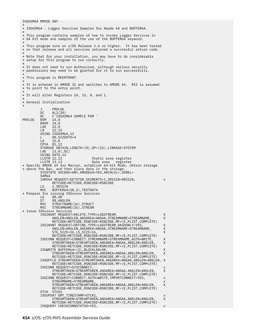
IXGASM64 RMODE ANY * * IXGASM64 - Logger Services Samples for Amode 64 and BUFFER64. * * This program contains samples of how to invoke Logger Services in * 64 bit mode and samples of the use of the BUFFER64 keyword. * * This program runs on z/OS Release 1.6 or higher. It has been tested * on that release and all services returned a successful return code. * * Note that for your installation, you may have to do considerable * setup for this program to run correctly. * * It does not need to run Authorized, although various security * permissions may need to be granted for it to run successfully. * * This program is REENTRANT. * * It is entered in AMODE 31 and switches to AMODE 64. R15 is assumed * to point to the entry point. * * It will alter Registers 14, 15, 0, and 1. * * General Initialization * J PROLOG DC AL1(20) DC C'IXGASM64 SAMPLE PGM ' PROLOG BSM 14,0 BAKR 14,0 LAE 12,0 LR 12,15 USING IXGASM64,12 L 00,SIZDATD+4 LA 15,0 CPYA 01,12 STORAGE OBTAIN,LENGTH=(0),SP=(15),LINKAGE=SYSTEM LAE 13,0(,01) USING DATD,13 LLGTR 12,12 Static area register LLGTR 13,13 Data area register * Specify AMODE 64 for Macros, establish 64-bit Mode, obtain storage * above the Bar, and then place data in the storage. SYSSTATE ASCENV=ANY,AMODE64=YES,ARCHLVL=,OSREL= SAM64 IARV64 REQUEST=GETSTOR,SEGMENTS=1,ORIGIN=ORIGIN, x RETCODE=RETCODE,RSNCODE=RSNCODE LG 2,ORIGIN MVC BUFFER64(50,2),TESTDATA * Prepare for issuing IXGxxxxx Services LA 08,40 ST 08,ANSLEN MVC STRUCTNAME(16),STRUCT MVC STREAMNAME(26),STREAM * Issue IXGxxxxx Services IXGINVNT REQUEST=DELETE,TYPE=LOGSTREAM, X ANSLEN=ANSLEN,ANSAREA=ANSAA,STREAMNAME=STREAMNAME, X RETCODE=RETCODE,RSNCODE=RSNCODE,MF=(E,PLIST,COMPLETE) IXGINVNT REQUEST=DEFINE,TYPE=LOGSTREAM,DASDONLY=YES, X ANSLEN=ANSLEN,ANSAREA=ANSAA,STREAMNAME=STREAMNAME, X STG_SIZE=16,LS_SIZE=16, X RETCODE=RETCODE,RSNCODE=RSNCODE,MF=(E,PLIST,COMPLETE) IXGCONN REQUEST=CONNECT,STREAMNAME=STREAMNAME,AUTH=WRITE, X STREAMTOKEN=STREAMTOKEN,ANSAREA=ANSAA,ANSLEN=ANSLEN, X RETCODE=RETCODE,RSNCODE=RSNCODE,MF=(E,PLIST,COMPLETE) IXGWRITE BUFFER64=(2),BLOCKLEN=50, X STREAMTOKEN=STREAMTOKEN,ANSAREA=ANSAA,ANSLEN=ANSLEN, X RETCODE=RETCODE,RSNCODE=RSNCODE,MF=(E,PLIST,COMPLETE) IXGOFFLD STREAMTOKEN=STREAMTOKEN,ANSAREA=ANSAA,ANSLEN=ANSLEN, X RETCODE=RETCODE,RSNCODE=RSNCODE,MF=(E,PLIST,COMPLETE) IXGCONN REQUEST=DISCONNECT, x STREAMTOKEN=STREAMTOKEN,ANSAREA=ANSAA,ANSLEN=ANSLEN, X RETCODE=RETCODE,RSNCODE=RSNCODE,MF=(E,PLIST,COMPLETE) IXGCONN REQUEST=CONNECT,AUTH=WRITE,IMPORTCONNECT=YES, x STREAMNAME=STREAMNAME, x STREAMTOKEN=STREAMTOKEN,ANSAREA=ANSAA,ANSLEN=ANSLEN, X RETCODE=RETCODE,RSNCODE=RSNCODE,MF=(E,PLIST,COMPLETE) STCK STCK1 IXGUPDAT GMT_TIMESTAMP=STCK1, x STREAMTOKEN=STREAMTOKEN,ANSAREA=ANSAA,ANSLEN=ANSLEN, X RETCODE=RETCODE,RSNCODE=RSNCODE,MF=(E,PLIST,COMPLETE) IXGQUERY CHECKCONNSTATUS=YES, x
414 z/OS: z/OS MVS Assembler Services Guide

STREAMTOKEN=STREAMTOKEN,ANSAREA=ANSAA,ANSLEN=ANSLEN, X RETCODE=RETCODE,RSNCODE=RSNCODE,MF=(E,PLIST,COMPLETE) IXGBRWSE REQUEST=START,OLDEST,BROWSETOKEN=BROWSETOKEN, x STREAMTOKEN=STREAMTOKEN,ANSAREA=ANSAA,ANSLEN=ANSLEN, X RETCODE=RETCODE,RSNCODE=RSNCODE,MF=(E,PLIST,COMPLETE) STCK STCK1 IXGIMPRT BUFFER64=(2),BLOCKLEN=50,BLOCKID=BLOCKID, X GMT_TIMESTAMP=STCK1,LOCALTIME=STCK1, x STREAMTOKEN=STREAMTOKEN,ANSAREA=ANSAA,ANSLEN=ANSLEN, x RETCODE=RETCODE,RSNCODE=RSNCODE,MF=(E,PLIST,COMPLETE) IXGBRWSE REQUEST=READCURSOR,BROWSETOKEN=BROWSETOKEN, x BUFFER64=(2),BUFFLEN=50,DIRECTION=OLDTOYOUNG, x BLKSIZE=RETURNSIZE,RETBLOCKID=RETBLOCKID, x STREAMTOKEN=STREAMTOKEN,ANSAREA=ANSAA,ANSLEN=ANSLEN, X RETCODE=RETCODE,RSNCODE=RSNCODE,MF=(E,PLIST,COMPLETE) IXGBRWSE REQUEST=END,BROWSETOKEN=BROWSETOKEN, x STREAMTOKEN=STREAMTOKEN,ANSAREA=ANSAA,ANSLEN=ANSLEN, X RETCODE=RETCODE,RSNCODE=RSNCODE,MF=(E,PLIST,COMPLETE) IXGDELET BLOCKS=ALL, x STREAMTOKEN=STREAMTOKEN,ANSAREA=ANSAA,ANSLEN=ANSLEN, X RETCODE=RETCODE,RSNCODE=RSNCODE,MF=(E,PLIST,COMPLETE) IXGCONN REQUEST=DISCONNECT, x STREAMTOKEN=STREAMTOKEN,ANSAREA=ANSAA,ANSLEN=ANSLEN, X RETCODE=RETCODE,RSNCODE=RSNCODE,MF=(E,PLIST,COMPLETE) IXGINVNT REQUEST=DELETE,STREAMNAME=STREAMNAME,TYPE=LOGSTREAM, x ANSAREA=ANSAA,ANSLEN=ANSLEN, X RETCODE=RETCODE,RSNCODE=RSNCODE,MF=(E,PLIST,COMPLETE) * Cleanup and return to caller L 00,SIZDATD+4 LA 15,0 LR 01,13 CPYA 01,13 STORAGE RELEASE,LENGTH=(0),ADDR=(1),SP=(15),LINKAGE=SYSTEM SLR 15,15 PR * Static data STATDATA DS 0F SIZDATD DS 0A DC AL1(0) DC AL3(DYNSIZE) DC A(DYNSIZE) TESTDATA DC CL50'TEST DATA FOR TESTCASE IXGASM64 ' STREAM DC CL26'LOGGER.STREAMA ' STRUCT DC CL16'LIST01 ' BLOCKID DC A(0) Blockid is 8 bytes in length DC A(256) BUFFER64 EQU 0 * Dynamic Data DATD DSECT SA00001 DS 36F Save area must be first in DATD RSNCODE DS F RETCODE DS F ANSLEN DS F RETURNSIZE DS F DS 0D STCK1 DS CL8 ORIGIN DS CL8 RETBLOCKID DS CL8 STRUCTNAME DS CL16 STREAMNAME DS CL26 STREAMTOKEN DS CL16 IXGANSAA DSECT=NO BROWSETOKEN DS CL4 PLIST DS CL256 BUFFER DS CL50 ORG *+1-(*-DATD)/(*-DATD) ENDDATD DS 0X DYNSIZE EQU ((ENDDATD-DATD+7)/8)*8 IXGASM64 CSECT , END
Synchronous and asynchronous processingDepending on the operating environment, an event control block (ECB) can be resident in one of twoplaces: the home address space (in private storage) or in common storage.
Chapter 27. Using system logger services 415

Use the MODE parameter on the IXGWRITE, IXGBRWSE, and IXGDELET services to choose one of thefollowing:
• MODE=SYNC• MODE=SYNCECB• MODE=SYNCEXIT• MODE=ASYNCNORESPONSE
The following conditions shows where the ECB might appear in an environment that includes a calleraddress space, a server address space, and the system logger address space. In these conditions, theserver provides services to the caller.
• Choosing MODE=SYNC
Choose MODE=SYNC to specify that the request be processed synchronously. When control returns tothe caller, all processing on behalf of the request is complete.
• Choosing MODE=SYNCECB
Choose MODE=SYNCECB to specify that the request be processed synchronously, if possible. If thesystem logger request cannot be completed synchronously, processing on behalf of the request mightstill be in progress when control returns to the caller (see MODE=ASYNCNORESPONSE). When theasynchronous processing for the request completes, the ECB specified on the system logger request isposted. Once the ECB is posted, the caller can examine the answer area to verify whether the requestcompleted successfully.
• Choosing MODE=ASYNCNORESPONSE
Choose MODE=ASYNCNORESPONSE on the IXGWRITE and IXGDELET requests to specify that therequest be processed asynchronously. The caller will not be informed when the request completes. Theanswer area returned in the ANSAREA parameter and mapped by IXGANSAA is not valid when youspecify MODE=ASYNCNORESPONSE.
When a system logger request cannot be completed synchronously, system logger indicates this byreturning to the invoking program with a specific return code X'4' and reason code X'401'(IxgRetCodeWarning and IxgRsnCodeProcessedAsynch, re: macro IXGCON).
Before system logger returns control to the caller it schedules an SRB to complete processing of therequest. While the SRB runs independent of the requesting task, the SRB might encounter an error fromwhich it cannot recover. The SRB ensures that the error condition is percolated to the task that issued thesystem logger request.
Note: Depending on the exploiter's structure, this task might not be the same task that originally issuedthe IXGCONN request to connect to a log stream.
Prior to percolating the error to the requesting task, system logger issues the SETRP macro, specifyingSERIAL=YES. System logger also places additional diagnostic information in the SDWA, as follows:SDWACMPC
The completion code, set to X'1C5'.SDWACRC
The reason code, set to X'85F'.SDWACOMU
The ECB address specified on the ECB keyword when system logger was invoked.
If the caller receives a return code indicating that system logger will process the request asynchronously,the application cannot free certain storage areas.
Reference information: See z/OS MVS Programming: Assembler Services Reference IAR-XCT for thespecific service's return code.
416 z/OS: z/OS MVS Assembler Services Guide

How system logger handles gaps in the log streamSystem logger might find data unexpectedly missing from or inaccessible in a log stream. These areas ofmissing information are called gaps and result from the following:
• System, sysplex, or coupling facility failure where the data could not be recovered.• A DASD log stream data set being deleted.• DASD I/O errors occurring during processing of an IXGBRWSE request to read log data.
If system logger encounters a gap during the processing of an IXGBRWSE or IXGDELET service, it returnsa return and reason code to the caller of the system logger service to report the condition and indicatewhether the service completed successfully. The other system logger services, IXGINVNT, IXGCONN, andIXGWRITE, are not affected by gaps in the log stream data.
See Table 39 on page 417 and Table 40 on page 417 for a summaries of how IXGBRWSE and IXGDELETservices handle gaps in the log stream.
Table 39. How IXGBRWSE Requests Handle Gaps in a Log Stream
IXGBRWSE Request Request Results
START SEARCH=search
READBLOCK SEARCH=search
Request completes with a non-zero return code and reason code.System logger positions the cursor at or reads the next youngest logblock or a block with an identical time stamp, if there is one.
START STARTBLOCKID=startblockid Request completes with a non-zero return code and reason code.System logger positions the cursor at or reads the next youngest logblock, if one exists.
READBLOCK BLOCKID=blockid Request fails with a non-zero return and reason code. No block isreturned.
READCURSOR Request completes with a non-zero return code and reason code.System logger reads the next valid block after the gap in thespecified direction, if there is one.
START OLDEST
RESET POSITION=OLDEST
When the oldest log block is within a gap of log data, the requestcompletes with a non-zero return code and reason code. Systemlogger positions or resets the cursor to the oldest valid block in thelog stream.
START YOUNGEST
RESET POSITION=YOUNGEST
The service completes without errors.
Table 40. How IXGDELET Requests Handle Gaps in a Log Stream
IXGDELET Request Request Results
BLOCKS=ALL This request is unaffected by gaps in the log stream. The servicecompletes successfully.
BLOCKS=RANGE If the block specified is at the start of the range specified, theservice fails with a non-zero return and reason code. No data isdeleted.
System logger returns the block identifier of the first accessibleblock toward the young end of the log stream.
If the block specified is not within a gap, the service completessuccessfully.
Dumping on data loss (804–type) conditionsThe DIAG option on the IXGINVNT service and IXCMIAPU TYPE(LOGR|LOGRY|LOGRZ) utility along withthe new DIAG options on the IXGCONN, IXGDELET and IXGBRWSE services allow additional diagnosticdata to be obtained when a log stream loss of data condition is encountered.
Chapter 27. Using system logger services 417

The following shows the default settings for all the services and the relationship between the servicespecifications in terms of whether or not Logger will request a dump for certain loss of data typeconditions.
Default settings:
DEFINE LOG STREAM DIAG(NO) IXGCONN (CONNECT) DIAG(NO_DIAG) IXGBRWSE (START) DIAG(NO_DIAG) IXGDELET DIAG(NO_DIAG)
Assuming a data loss (804) type condition was encountered on an IXGDELET request or on anyIXGBRWSE request for a browse session, the following shows whether or not a dump would be taken byLogger for this condition, where:No
No dump is taken for the condition.Yes
Dump is taken for the condition.
DEFINE LOG STREAM NO YES ----------------- ----------------- IXGCONN CONNECT NO_DIAG NO YES NO_DIAG NO YES ----------------------------------------------------------------
IXGBRWSE START NO_DIAG no no no no no yes NO no no no no no no YES no no no yes no yes
IXGDELET NO_DIAG no no no no no yes NO no no no no no no YES no no no yes no yes
Note: The specification on DIAG(YES) in the log stream definition also results in additional non-abenddiagnostics being collected for the log stream. For more information, see 'Enabling additional log streamdiagnostics' in z/OS MVS Diagnosis: Reference.
Define a log stream to allow additional dumping• IXGINVNT
Specify IXGINVNT REQUEST=DEFINE,TYPE=LOGSTREAM,...,DIAG=YES• IXCMIAPU Utility Program
Specify DEFINE LOGSTREAM ... DIAG(YES)
Define a log stream to allow additional dumping using LIKE• IXGINVNT
Specify IXGINVNT REQUEST=DEFINE,TYPE=LOGSTREAM,NAME=like.log.stream,...,DIAG=YES
Then IXGINVNT REQUEST=DEFINE,TYPE=LOGSTREAM,LIKE=like.log.stream• IXCMIAPU Utility Program
Specify DEFINE LOGSTREAM NAME (like.log.stream) ... DIAG(YES)
Then DEFINE LOGSTREAM LIKE(like.log.stream)
Update a log stream to allow additional dumping• IXGINVNT
418 z/OS: z/OS MVS Assembler Services Guide

Specify IXGINVNT REQUEST=UPDATE,TYPE=LOGSTREAM,...,DIAG=YES• IXCMIAPU Utility Program
Specify UPDATE LOGSTREAM ... DIAG(YES)
The update will take affect as each system obtains its first connection to the log stream. For example,assume there are two systems in an installation's sysplex, SYSA and SYSB, and SYSA had a connection tothe log stream prior to the update request and SYSB did not have any connections to the log stream. IfSYSB establishes a new (first) connection to the log stream, then the DIAG options will be in affect onSYSB. The DIAG settings prior to the update request will remain in affect on SYSA even if there is anotherconnection to the log stream on SYSA. However, if all the connections to the log stream on SYSA aredisconnected and then a new (first) connection is established to the logstream on SYSA, then the newDIAG options would then be in affect on SYSA.
Connect to a log stream and request additional dumping• IXGCONN
Specify IXGCONN REQUEST=CONNECT,...,DIAG=YES
Assuming the log stream that is being connected has been defined as DIAG(YES), then Logger will providea dump when a loss of data condition is encountered on browse and delete requests, unless the specificbrowse (start) or delete request specifies otherwise.
Browsing a log stream and request additional dumping• IXGBRWSE
Specify IXGBRWSE REQUEST=START,...,DIAG=YES when IXGCONNREQUEST=CONNECT,...,DIAG=NO_DIAG
• IXGCONN
Specify IXGCONN REQUEST=CONNECT,...,DIAG=YES then no specific DIAG options need to be coded onthe IXGBRWSE REQUEST=START invocation.
Assuming the log stream that is being browsed has been defined as DIAG(YES), then Logger will provide adump when a loss of data condition is encountered on any browse for this browse session.
Deleting log data from a log stream and request additional dumping• IXGDELET
Specify IXGDELET,...,DIAG=YES when IXGCONN REQUEST=CONNECT,...,DIAG=NO_DIAG• IXGCONN
Specify IXGCONN REQUEST=CONNECT,...,DIAG=YES then no specific DIAG options need to be coded onthe IXGDELET invocation.
Assuming the log stream that is having log data deleted has been defined as DIAG(YES), then Logger willprovide a dump when a loss of data condition is encountered on this delete request.
Using the system logger answer area (ANSAREA parameter)Every system logger service issued must include an answer area output field specified on the ANSAREAparameter. In this answer area, mapped by the IXGANSAA macro, system logger returns status anddiagnostic data.
Some generic answer area fields include:
ANSAA_PREFERRED_SIZEThe optimal size for the answer area field specified on the ANSAREA parameter. IXGCONNREQUEST=CONNECT returns this value.
Chapter 27. Using system logger services 419

The answer area must be at least 40 bytes long. If you specify a field that is less than that, the servicefails with a non-zero return code. To ascertain the optimal answer area size, look at theANSAA_PREFERRED_SIZE field of the answer area returned by the first system logger service yourapplication issues, either the IXGINVNT or IXGCONN REQUEST=CONNECT service.
ANSAA_ASYNCH_RETCODEFor asynchronously processed requests, system logger returns the return code in this field.
ANSAA_ASYNCH_RSNCODEFor asynchronously processed requests, system logger returns the reason code in this field.
ANSAA_DIAGxDiagnostic data. The content of these fields depend on any return and reason codes returned for arequest.
Specific service indicators include:
ANSAA_BLKFROMINACTIVEIndicates that the log block returned from an IXGBRWSE request came from the inactive portion ofthe log stream. For MULTIBLOCK=YES requests, this flag indicates that at least one log block returnedin the buffer came from an inactive portion of the log stream. Flag IXGBRMLT_FROMINACTIVE inIXBRMLT (from the IXGBRMLT macro) indicates which log blocks were in the inactive portion. Thisfield is only valid for IXGBRWSE requests that result in a log block being returned.
ANSAA_DYNMGMTOFENTRYTOELACTIVEIndicates that system logger is dynamically managing the entry-to-element ratio for the couplingfacility structure. The structure was defined in a LOGR couple data set. This field is only valid forIXGCONN requests, and is undefined when ANSA_DASDONLYLOGSTREAM is on.
ANSAA_DASDONLYLOGSTREAMThis flag in ANSAA_FLAGS1 indicates whether a log stream is DASD-only. It is output from anIXGCONN REQUEST=CONNECT service.
ANSAA_BROWSEMULTIBLOCKThis flag in ANSAA_FLAGS1 indicates whether this level of system logger supports IXGBRWSEMULTIBLOCK=YES requests. It is valid only for an IXGBRWSE REQUEST=START service.
ANSAA_BLKFROMDASDThis flag in ANSAA_FLAGS1 indicates that the log block returned from an IXGBRWSE request camefrom a log stream DASD offload data set. For MULTIBLOCK=YES requests, this flag indicates that atleast one log block returned in the buffer came from a log stream DASD offload data set. FlagIXGBRMLT_FROMDASD in IXBRMLT (from the IXGBRMLT macro) indicates which log blocks were readfrom DASD. This field is only valid for IXGBRWSE requests that result in a log block being returned.
ANSAA_USECDSTYPEISSETThis flag in ANSAA_USECDSTYPE (ANSAA_FLAGS3) indicates when one of the following explicit CDSdata type flags is set on.
When this indicator flag is not set on, it means the sysplex scope LOGR CDS data type is consideredfor use on this system. It is output only for an IXGCONN REQUEST=CONNECT , IXGINVNT, andIXGQUERY requests.
ANSAA_USECDSTYPELOGRThis flag in ANSAA_USECDSTYPE (ANSAA_FLAGS3) indicates when the sysplex scope LOGR CDS datatype is considered for use on this system.
This flag is valid only when ANSAA_USECDSTYPEISSET is also on.
ANSAA_USECDSTYPELOGRYThis flag in ANSAA_USECDSTYPE (ANSAA_FLAGS3) indicates when the single-system scope LOGRYCDS data type is expected for use on this system.
This flag is valid only when ANSAA_USECDSTYPEISSET is also on.
ANSAA_USECDSTYPELOGRZThis flag in ANSAA_USECDSTYPE (ANSAA_FLAGS3) indicates when the single-system scope LOGRZCDS data type is expected for use on this system.
420 z/OS: z/OS MVS Assembler Services Guide

This flag is valid only when ANSAA_USECDSTYPEISSET is also on.
For a complete description of the IXGANSAA macro, see z/OS MVS Data Areas in the z/OS Internet library(www.ibm.com/servers/resourcelink/svc00100.nsf/pages/zosInternetLibrary).
Using ENF event code 48 in system logger applicationsSystem logger issues ENF event code 48 to broadcast status changes in the system logger address space,log streams, and coupling facility structures. Since these status changes can affect the outcome of systemlogger service requests, IBM recommends that you use ENF event code 48 to receive notification of thesestatus changes, using the ENFREQ service to listen for event 48. Note that your program must beauthorized to use the ENFREQ service. Applications should issue the ENFREQ service to listen for event48 before connecting to a log stream.
Applications that do not want to use ENF event code 48 or that are unauthorized and cannot use ENFREQwill still receive logger service return and reason codes indicating failure or resource shortages. Theseapplications can then simply set a timer and then retry the requests to see if the problem has resolveditself.
References:
• See the z/OS MVS Programming: Authorized Assembler Services Guide for guidance about using theENFREQ macro.
• See the z/OS MVS Programming: Authorized Assembler Services Reference EDT-IXG for referenceinformation on the ENFREQ macro.
Note: The following topic has been moved to Coding a system logger complete exit for IXGBRWSE,IXGWRITE, and IXGDELET in z/OS MVS Programming: Authorized Assembler Services Guide.
IXGINVNT: Managing the LOGR, LOGRY and LOGRZ policiesThe IXGINVNT service allows your application program to manage and update the sysplex scope LOGRpolicy dynamically.
In addition to the sysplex scope LOGR policy, system logger supports up to two single-system scopepolicies, LOGRY and LOGRZ, in a sysplex. The LOGRY and LOGRZ policy information is similar to the LOGRpolicy information, except no structures can be defined by single-system scope policies and their logstreams must be DASD-only type. The log streams in the LOGRY and LOGRZ policies are managed asseparate resources from the log stream resources defined in the sysplex scope LOGR policy and the othersingle-system scope policy. Only one system in the sysplex can be using the LOGRY policy and only oneother system can be using the LOGRZ policy as their respective active CDS data type. A system cannot beusing the sysplex scope LOGR policy when a system is using either the LOGRY or LOGRZ single-systemscope policy.
The IXGINVNT macro can be used to define or update either the LOGRY or LOGRZ single-system scopepolicy information by executing the program request on the system that is using the intended single-system scope policy.
When you intend to specify LOGR policy information, you will need to execute the IXGINVNT macroprogram request on a system in the sysplex that is not using the single-system scope of LOGRY or LOGRZpolicies.
You can also use the IXCMIAPU utility to manage the sysplex scope LOGR policy or a single-system scopeLOGRY or LOGRZ policy (see z/OS MVS Setting Up a Sysplex). The reason and return codes for both theIXGINVNT service and the IXCMIAPU utility are documented with the reference information on theIXGINVNT service in z/OS MVS Programming: Assembler Services Reference IAR-XCT.
For guidance on specifying information in the sysplex scope LOGR couple data set or a single-systemscope LOGRY or LOGRZ couple data set using IXGINVNT or IXCMIAPU, see the system logger chapter ofz/OS MVS Setting Up a Sysplex.
Using IXGINVNT, your application program can:
Chapter 27. Using system logger services 421

• Define and update log streams definitions using REQUEST=DEFINE or REQUEST=UPDATE withTYPE=LOGSTREAM.
• Define a coupling facility structure associated with a log stream using REQUEST=DEFINE withTYPE=STRUCTURE (applies to LOGR policy only).
• Check whether a particular log stream or logger (coupling facility) structure definition exists in the activesystem logger couple data set policy using REQUEST=CHECKDEF.
• Delete log stream and coupling facility structure definitions using REQUEST=DELETE.
See "LOGRY and LOGRZ keywords and parameters for the administrative data utility" and "DEFINELOGSTREAM keywords and parameters" in z/OS MVS Setting Up a Sysplex for a comparison on thepertinent log stream keywords based on which system logger CDS type is being used.
Defining a model log stream in the LOGR couple data setUse the MODEL parameter on the IXGINVNT REQUEST=DEFINE service to define a dummy log streamthat other log stream definitions can reference. Using a model allows you to specify common log streamcharacteristics for many log streams only once.
This can streamline the process of defining new log streams in the active system logger couple data setpolicy, because you can specify the name of the model log stream on the LIKE keyword when you issuethe IXGINVNT service to define a new log stream. Note that any explicit definitions for the log stream youare defining override the definitions of the model log stream.
Figure 115 on page 422 shows how you can use the IXGINVNT service to define a log stream as a modeland then define a log stream modeled after it. The LS_DATACLAS parameter specifying the data class forthe log data sets for log stream STREAM1 overrides the LS_DATACLAS specified in the IXGINVNT requestfor log stream MODEL1.
IXGINVNT REQUEST=DEFINE TYPE=LOGSTREAM, STREAMNAME=MODEL1, STRUCTNAME=STRUCT1, MODEL=YES, HLQ=SYSPLEX1, STG_DUPLEX=YES, DUPLEXMODE=COND, STG_DATACLAS=STGDATA, STG_MGMTCLAS=STGMGMT, STG_STORCLAS=STGSTOR, LS_MGMTCLAS=LSMGMT, LS-STORCLAS=LSSTOR, LS_DATACLAS=LSDATA, STG_MGMTCLAS=LSMGMT, STG_STORCLAS=LSSTOR, ANSAREA=ANSAREA, ANSLEN=ANSLEN, RETCODE=RETCODE, RSNCODE=RSNCODE
IXGINVNT REQUEST=DEFINE TYPE=LOGSTREAM, STREAMNAME=STREAM1, LS_DATACLAS=LSDATA1 LIKE=MODEL1, ANSAREA=ANSARE1, ANSLEN=ANSLE1, RETCODE=RETCDE, RSNCODE=RSNCDE
Figure 115. Define a Log Stream as a Model and then Model a Log Stream After It
You cannot connect to a model log stream or use it to store log data. It is strictly for use as a model tostreamline the process of defining log streams.
You can use the LIKE parameter to reference a log stream that has not been defined as a model logstream using the MODEL parameter. Any log stream can be referenced on the LIKE parameter.
422 z/OS: z/OS MVS Assembler Services Guide

Defining a log stream as DASD-onlyYou can define a log stream as either a coupling facility log stream or DASD-only log stream using theDASDONLY parameter on the IXGINVNT REQUEST=DEFINE TYPE=LOGSTREAM service (see “The logstream” on page 406).
Specify or default to DASDONLY=NO, to define a coupling facility log stream. You must also specify astructure name on the STRUCTNAME parameter in the log stream definition for a coupling facility logstream.
Specify DASDONLY=YES, to define a DASD-only log stream, which is not associated with a coupling facilitystructure. When you define a DASD-only log stream, you can also specify MAXBUFSIZE to define themaximum buffer size that can be written to the DASD-only log stream. (For a coupling facility log stream,MAXBUFSIZE is specified on the IXGINVNT REQUEST=DEFINE TYPE=STRUCTURE request to define themaximum log block size that can be written to the log stream.)
Note that a DASD-only log stream is single-system in scope - only one system may write to a DASD-onlylog stream.
For set up steps for a DASD-only log stream, see the system logger chapter in z/OS MVS Setting Up aSysplex.
Upgrading an existing log stream configurationYou can upgrade a DASD-only log stream to use coupling facility storage, making it a coupling facility logstream, or you can upgrade an existing structure-based log stream to use a different coupling facilitystructure. To upgrade to a structure-based log stream, associate the structure with the log stream byupdating the log stream definition in the LOGR policy. Use the UPDATE request on either the IXGINVNTservice or the IXCMIAPU utility to specify the name of the coupling facility structue with theSTRUCTNAME parameter. All connectors to either the DASD-only log stream or the existing structure-based log stream being upgraded must be disconnected in order to make the upgrade. No failed or activeconnections can exist for the log stream.
When updating an existing log stream configuration, the GROUP attribute must be taken into account.
For details about updating the GROUP parameter, see "Parameters for REQUEST=UPDATE" under thetopic of IXGINVNT in z/OS MVS Programming: Assembler Services Reference IAR-XCT.
For examples of log stream configuration changes, see Upgrading an existing log stream configuration inz/OS MVS Setting Up a Sysplex.
Upgrading a log stream from DASD-only to coupling facilityYou can upgrade a log stream defined as DASD-only (DASDONLY=YES parameter on the log streamdefinition) to a coupling facility log stream. Do this by issuing the IXGINVNT REQUEST=UPDATE servicewith the STRUCTNAME parameter to associate a structure with the log stream.
To upgrade a log stream from DASD-only to coupling facility, the following must be true:
• The structure specified on the STRUCTNAME parameter must be defined in a structure definition in theLOGR policy.
• All connections (active or failed) to the log stream must be disconnected.
Before connecting to or issuing any system logger services against an upgraded log stream, you must alsomake sure that the structure associated with the log stream is specified in the CFRM policy couple dataset.
For guidance on upgrading a DASD-only log stream to a coupling facility based one, see the system loggerchapter in z/OS MVS Setting Up a Sysplex.
Chapter 27. Using system logger services 423

Updating an existing structure-based log stream to another structureYou can update an existing structure-based log stream to use a different coupling facility structure. Dothis by issuing the IXGINVNT REQUEST=UPDATE service with the STRUCTNAME parameter to identify thenew structure to be associated with the log stream.
To upgrade a structure-based log stream to use a new coupling facility structure, the following must betrue:
• The LOGR couple data set must be formatted at a z/OS Version 1 Release 2 (HBB7705) level or later.• The IXGINVNT request must be submitted on a system at z/OS Version 1 Release 3 or later.• The structure specified on the STRUCTNAME parameter must be defined in a structure definition in the
LOGR policy.• All connections (active or failed) to the log stream must be disconnected.
Before connecting to or issuing any system logger services against an upgraded log stream, you must alsomake sure that the structure associated with the log stream is specified in the CFRM policy couple dataset.
Sample procedures to update an existing structure-based log stream to anotherstructureYou can use one of the these sample procedures to perform a non-destructive or destructive update of anexisting structure-based log stream to another structure.
Steps for a non-destructive update of an existing structure-based log streamUse this sample procedure to perform a non-destructive update, which will maintain any existing logstream data.
1. Define a new new-structure-name structure definition in the CFRM policy that has the appropriateSIZE, INITSIZE, and other attributes defined, and ensure that this new structure is in the current CFRMpolicy for the sysplex.
2. Define a new new-structure-name structure in the LOGR policy with attributes MAXBUFSIZE,AVGBUFSIZE, and LOGSNUM, as needed.
3. Cause the exploiter to disconnect from the persistent-log-stream log stream.4. Confirm that no connections remain to the log stream in the sysplex. For example, you can issue the
following system command:
DISPLAY LOGGER,L,LSN=persistent-log-stream
The status will be AVAILABLE when there are no more connections.5. Update the persistent-log-stream log stream definition in the LOGR policy to map it to the newly
defined new-structure-name structure. For example:
IXCMIAPU type(logr)UPDATE LOGSTREAM NAME(persistent-log-stream) STRUCTNAME(new-structure-name)
6. Cause the exploiter to connect to the persistent-log-stream log stream.7. Confirm that the exploiter is connected on the expected z/OS images. For example:
DISPLAY LOGGER,L,LSN=persistent-log-stream
Steps for a destructive update of an existing structure-based log streamUse this sample procedure to perform a destructive update, which will delete the log stream and anyexisting data.
1. Cause the exploiter to disconnect from the original-log-stream log stream.2. Confirm that no connections remain to the log stream in the sysplex. For example, you can issue the
following system command:
424 z/OS: z/OS MVS Assembler Services Guide

DISPLAY LOGGER,L,LSN=original-log-stream
The status will be AVAILABLE when there are no more connections.3. Delete the original-log-stream log stream from the LOGR policy.4. Delete the original-structure structure from the LOGR policy.5. Redefine the structure in the LOGR policy with the original-structure name and attributes
MAXBUFSIZE, AVGBUFSIZE, and LOGSNUM, as needed.6. Redefine the log stream in the LOGR policy with the original-log-stream name and map it to the
redefined original-structure structure.7. Cause the exploiter to connect to the newly defined original-log-stream log stream.8. Confirm that the exploiter is connected on the expected z/OS images. For example:
DISPLAY LOGGER,L,LSN=original-log-stream
Renaming a log stream dynamicallyYou can rename a log stream dynamically using the NEWSTREAMNAME keyword on the IXGINVNTREQUEST=UPDATE request. Since many logging programs use a fixed log stream name, this function canbe very useful for log stream recovery. For example, if a log stream fails, the system might not be able toperform any logging for the log stream that has failed. Using the log stream rename function, you canrename the failing log stream and then use IXGINVNT REQUEST=DEFINE to define a new log stream withthe old name in order to start logging again. This function allows you to perform the following functions:
• Save the current data in a renamed log stream and start logging quickly by defining a new log streamwith the expected name
• Let existing services and utilities access the data in the renamed log stream to reduce the effect ofhaving some data missing from the log stream
• Perform problem diagnosis, such as data missing conditions, on the original (renamed) log streamresources at the same time that new work continues
You must have an active primary TYPE(LOGR) couple data formatted at an HBB7705 level or higher, or beoperating against a TYPE(LOGRY) or TYPE(LOGRZ) couple data set, in order to specify theNEWSTREAMNAME parameter.
For information, see:
• Renaming a log stream dynamically in z/OS MVS Setting Up a Sysplex.• IXGINVNT - Managing the LOGR, LOGRY and LOGRZ inventory couple data sets in z/OS MVS
Programming: Assembler Services Reference IAR-XCT.• The IXCMIAPU UPDATE LOGSTREAM request in z/OS MVS Setting Up a Sysplex.
Updating a log stream's attributesYou can update certain attributes of a DASD-only or coupling facility log stream using either theIXGINVNT UPDATE service or the IXCMIAPU utility. The updates are immediately reflected in the logstream definition in the intended active LOGR, LOGRY or LOGRZ couple data set, but some remainpending and do not take effect until specific events occur during processing as described in this section.
See "LOGRY and LOGRZ keywords and parameters for the administrative data utility" and "UPDATELOGSTREAM keywords and parameters" in z/OS MVS Setting Up a Sysplex for a comparison on thepertinent log stream keywords based on which system logger CDS type is being used.
The following attributes can be updated while there is an outstanding (active or failed-persistent)connection to the log stream. Some of the updates will not take effect immediately if there is anoutstanding connection. In order to update these attributes, the LOGR couple data set must be formattedat least at a certain format level or be operating against a LOGRY or LOGRZ type couple data set. See
Chapter 27. Using system logger services 425

"LOGR parameters for format utility (sysplex scope)" and "LOGRY or LOGRZ single-system scopeparameters for format utility" in z/OS MVS Setting Up a Sysplex for more details.
Note: If this requirement is not met, the UPDATE request fails.
Pending updates will take effect at different points for each log stream attribute as follows:
• The RETPD and AUTODELETE attribute updates take effect when a new offload data set is allocated(data set switch event) or on the subsequent first connection to the log stream in the sysplex.
• The LS_DATACLASS, LS_SIZE, LS_MGMTCLASS, LS_STORCLASS, and LS_ALLOCAHEAD attributeupdates will remain pending until a new offload data set is allocated (data set switch event) or on thesubsequent first connection to the log stream in the sysplex. For a coupling facility log stream, theupdate also takes effect during the next structure rebuild (user-managed or system-managed).
• The LOWOFFLOAD, HIGHOFFLOAD, OFFLOADRECALL, STG_DATACLAS, STG_MGMTCLAS,STG_STORCLAS, STG_SIZE, and WARNPRIMARY attribute updates remain pending until the subsequentfirst connection to the log stream in the sysplex. For a coupling facility log stream, the update also takeseffect during the next structure rebuild (user-managed or system-managed). The STG_DATACLAS,STG_MGMTCLAS, STG_STORCLAS, and STG_SIZE attribute updates are also committed when a newstaging data set needs to be allocated following one of the preceding conditions. In the case of a DASD-only logstream, the HIGHOFFLOAD, LOWOFFLOAD, OFFLOADRECALL, and WARNPRIMARY attributeupdates are also committed on the next offload data set switch.
• The LOGGERDUPLEX, STG_DUPLEX, and DUPLEXMODE attribute updates for a structure-basedlogstream remain pending until the subsequent first connection to the log stream in a sysplex or untilthe next successful structure rebuild (user-managed).
• The MAXBUFSIZE attribute update remains pending until the subsequent first connection to the DASD-only log stream in the sysplex.
• The ZAI and ZAIDATA attributes can be updated while there is an outstanding connection to the logstream. In this case, the change will immediately be reflected in the log stream definition. The updatedspecification will take effect on the following logger events for this log stream:
1. On the subsequent first connection to the log stream on a system (z/OS image).2. As a result of a SETLOGR FORCE,ZAICONN,LSN= command on the target system. or3. As a result of a SETLOGR FORCE,ZAICONN,ALL command when there is a connection to this log
stream currently using the ZAI=YES setting on the target system.
Note: Since the updated value can be used on a system by system basis, the installation should ensurethe proper actions are taken on all the systems with connections to the log stream in order to make useof the current value.
IXGCONN: Connecting to and disconnecting from a log streamUse the IXGCONN service to connect to or disconnect from a log stream. An application must issueIXGCONN with REQUEST=CONNECT before it can read, write, or delete data in a log stream.
When the IXGCONN REQUEST=CONNECT request completes, it returns a unique connection identifier,called a STREAMTOKEN, to the calling program. The application uses the token in subsequent loggerservice requests to identify its connection to the log stream.
In the answer area (IXGANSAA) returned by IXGCONN, bit Ansaa_DynMgmtOffEntryToEleActive is onwhen system logger is dynamically managing the entry-to-element ratio. See the system logger chapter inz/OS MVS Setting Up a Sysplex for information about dynamic management of the entry-to-element ratio.
For IXGCONN REQUEST=CONNECT AUTH=WRITE, bit Ansaa_WriteTriggersReturned indicates IXGWRITErequests may have the Ansaa_WriteTriggers filled in the answer area of the IXGWRITE. See “Writetriggers” on page 434 for additional information.
Additionally, for IXGCONN REQUEST=CONNECT AUTH=WRITE, output answer area indicator flagsAnsaa_WriteConnectLimitedAccess and Ansaa_WriteOnlyAccess indicates when the log streamconnection token can only be used to write log data into the log stream (IXGWRITE) and disconnect from
426 z/OS: z/OS MVS Assembler Services Guide

the log stream (IXGCONN). No other log stream access services are allowed for this connection type. Also,import type connections are not allowed in combination with this limited access type of log streamconnection.
Note: The following services contain parameters for both authorized and unauthorized programs:IXGCONN, IXGBRWSE, IXGWRITE, and IXGDELET. All other system logger services and their parameterscan be used by any program. All the unauthorized guidance for system logger is contained in this chapter.The following topics have moved to the Authorized Assembler Services Guide:
• Connecting as a resource manager in z/OS MVS Programming: Authorized Assembler Services Guide• Using ENF event 48 when a connect request is rejected in z/OS MVS Programming: Authorized
Assembler Services Guide• Coding a resource manager exit for IXGCONN in z/OS MVS Programming: Authorized Assembler Services
Guide.
Examples of ways to connect to the log streamAn application can connect to the log stream in different ways. Some of these are:
• One connection per address space: Once a program has connected to a log stream, any task running inthe same address space shares the connect status and can use the same stream token to issue othersystem logger services. Any task in the address space can disconnect the entire address space from thelog stream by issuing the IXGCONN REQUEST=DISCONNECT service.
• One connection per program: One or more tasks in a single address space can issue IXGCONNREQUEST=CONNECT individually to connect to the same log stream and receive separate streamtokens. Each program must disconnect from the log stream individually.
• Multiple systems connecting to a log stream: Multiple address spaces on one or more MVS systemscan connect to a single coupling facility log stream, but each one must issue IXGCONN individually toconnect and then disconnect from the log stream. Each one receives a unique stream token; addressspaces cannot share a stream token.
When an application issues IXGCONN to connect to a coupling facility log stream, the system loggeraddress space connects to the coupling facility list structure for the log stream.
Each task that issues IXGCONN REQUEST=CONNECT to connect to a log stream must later issueIXGCONN REQUEST=DISCONNECT to disconnect from the log stream. When a task disconnects from thelog stream, the stream token that identified the connection is invalidated. Any requests that use thestream token after the disconnect will be rejected.
If a task that issued the IXGCONN REQUEST=CONNECT request ends before issuing a disconnect request,system logger will automatically disconnect the task from the log stream. This means that the unique logstream connection identifier, or the STREAMTOKEN, will no longer be valid. The application will receive an“expired logstream token” error response if it then uses this same STREAMTOKEN after the task has beendisconnected on subsequent logger service requests.
Additional considerations for connecting to a DASD-only log streamIf you are writing an application for a DASD-only log stream, you must keep in mind that a DASD-only logstream is single-system in scope, meaning that only one system at a time can connect to a DASD-only logstream. (See “The log stream” on page 406 for a description of the two different types of log streams.)Multiple applications from the same system can connect to a DASD-only log stream, but only from onesystem at a time. An application trying to connect to a DASD-only log stream that already has anothersystem connected will fail. A second system cannot connect to the DASD-only log stream until the firstone disconnects.
The ANSAA_DASDONLYLOGSTREAM flag in the IXGANSAA mapping macro indicates whether a logstream is DASD-only.
Chapter 27. Using system logger services 427

When an application issues the IXGCONN request to connect to a DASD-only log stream, theSTUCTNAME, AVGBUFSIZE, and ELEMENTSIZE will be returned containing hexidecimal zeros, becausethey are all coupling facility structure related fields.
How system logger allocates structure space for a new log stream atconnection time
The first IXGCONN request in a sysplex issued for a coupling facility log stream initiates the allocation ofcoupling facility space for the log stream.
If there are multiple coupling facility log streams assigned to one coupling facility structure, system loggerdivides the structure space evenly between each log stream that has applications connected to it viaIXGCONN. This means that the first log stream that has an IXGCONN service issued against it gets 100%of the coupling facility structure space available. When a second log stream mapping to the couplingfacility structure has an IXGCONN service issued against it, system logger divides the structure evenlybetween the two log streams. The first log stream's available coupling facility space will be reduced byhalf to reapportion the rest of the space to the second log stream. This can result in some of the databeing off-loaded to DASD if the coupling facility space allocated to a log stream reaches its high thresholdas a result of the reapportionment of the structure space.
For example, if an installation defines two log streams to a single structure in the LOGR policy, but onlyone of the log streams actually has a connected application, then that one log stream can use the entirecoupling facility structure. When the second log stream connect occurs against the coupling facilitystructure, the space is gradually divided between the two log streams. Likewise, when the last disconnectis issued against one of the two log streams, all coupling facility structure space is again available to thefirst log stream.
Note that this process of reallocation of coupling facility space and subsequent offloading of couplingfacility data might not take place immediately after the log stream connect. The reallocation of spacemight occur gradually, with an offloading taking place some time after the original log stream connect.
Connect process and staging data setsCoupling Facility Log Streams: If an installation defines DASD staging data sets for a coupling facility logstream, the data sets are created, if necessary, during connection processing for the first IXGCONNrequest issued against a log stream from a particular system.
DASD-Only Log Stream: For a DASD-only log stream, the staging data set is automatically created duringthe first connect issued against the log stream. A staging data set is not optional for a DASD-only logstream.
Requesting authorization to the log stream for an applicationUse the AUTH parameter to specify whether the application issuing IXGCONN should have read or writeaccess to the log stream:
• If you specify AUTH=READ for an application, that application will only be able to issue IXGCONN,IXGBRWSE, and IXGQUERY requests. For AUTH=READ, the caller must have SAF read access toRESOURCE(log_stream_name) in CLASS(LOGSTRM).
• If you specify AUTH=WRITE for an application, that application can issue any system logger log streamaccess service, unless the connection is only allowed limited log stream services access.
– To connect to a log stream with an AUTH=WRITE specification, SAF profiles covering two separateresources are used to determine if access is allowed and whether full access to log stream servicescan be used or just limited log stream access (only IXGWRITE and disconnect requests) can be usedfor the connection. Refer to each log stream exploiter's planning and/or guidance documentation ontheir log stream access requirements. Grant permission to SAF profile covering theRESOURCE(WRITE_ONLY_log-stream-name) only when deemed appropriate for the log streamexploiter.
428 z/OS: z/OS MVS Assembler Services Guide

- For full service WRITE log stream access, the caller must have update (or higher level) access toRESOURCE(log-stream-name) in SAF CLASS(LOGSTRM). When this level of access is granted, all logstream access services can be used with the log stream token established on this connection.
- For limited service WRITE log stream access, the caller must have (at least) update access toRESOURCE(WRITE_ONLY_log-stream-name) in SAF CLASS(LOGSTRM). When this level of access isgranted, only IXGWRITE and IXGCONN (to disconnect) requests can be used with the log streamtoken established on this connection.
- When there are no profiles defined covering RESOURCE(log-stream-name) orRESOURCE(WRITE_ONLY_log-stream-name) in SAF CLASS(LOGSTRM), then AUTH=WRITEconnection is permitted as full service access to the log stream.
- When just the profile covering RESOURCE(log-stream-name) is defined, meaning no profile coveringRESOURCE(WRITE_ONLY_log-stream-name), then the connected is permitted according to theRESOURCE(log-stream-name) profile access. Access to the log stream will either be full serviceaccess or the connection is not allowed (denied).
- When just the profile covering RESOURCE(WRITE_ONLY_log-stream-name) is defined, meaning noprofile covering RESOURCE(log-stream-name), then the connection is permitted based on theRESOURCE (WRITE_ONLY_log-stream-name) profile access. Access to the log stream will either belimited service log stream access (can only write log data and disconnect from the log stream), oraccess is the connection that is not allowed (denied).
- When profiles covering both RESOURCE(WRITE_ONLY_log-stream-name) and RESOURCE(log-stream-name) are defined, then the connection is permitted based on the following combinations:
• access is permitted via both profiles, then access to the log stream will be full service access.• access is permitted via RESOURCE(log-stream-name) profile, but is defined via
RESOURCE(WRITE_ONLY_log-stream-name) profile, then access to the log stream will be fullservice access.
• access is permitted via RESOURCE(WRITE_ONLY_log-stream-name) profile, but it is denied viaRESOURCE(log-stream-name) profile, then access to the log stream will be limited service (canonly write log data and disconnect from the log stream).
• access is not permitted (denied) via both profiles, then the connection to the log stream will notbe allowed (denied).
When permission is not allowed for the profiles covering the resources noted above, system loggerwill provide an error of return code 8, reason code X'080D' (IxgRsnCodeNoSAFAuth) on the logstream connection attempt.
• If the SAF authorization check indicates that a security product is not available or if a profile coveringthe LOGSTRM class for each respective resource identified above is not defined, then the access will beallowed. Therefore, the caller will be allowed to connect to the log stream with the requested AUTHparameter value.
The Table 41 on page 429 table shows the combinations and results for the different SAF profileauthorization access checking, performed by system logger, in determining whether the connector isallowed and how to use the log stream.
Table 41. Results for the different SAF profile authorization access checking performed by system logger
(WRITE_ONLY_log-stream-name)
profile
(log-stream-name) profile
RC=0 RC=4 RC=8
RC=0 Allow-full Allow-limited Allow-limited
RC=4 Allow-full Allow-full Not-allowed
RC=8 Allow-full Not-allowed Not-allowed
The Table 42 on page 430 table shows the system logger APIs and the error return information when thefunctional API request is not honored based on the established type of log stream connection.
Chapter 27. Using system logger services 429

Table 42. Logger log stream access services (API) behavior
Logger log stream API AUTH=READ on connect AUTH=WRITE on connect -full service access
AUTH=WRITE on connect -limited service access
IxgWritenot allowed
rc8, rsn X'81C'allowed allowed
IxgBrwse allowed allowednot allowed
rc8, rsn X'81C'
IxgDeletnot allowed
rc8, rsn X'81C'allowed
not allowed
rc8, rsn X'81C'
IxgOffldnot allowed
rc8, rsn X'81C'allowed
not allowed
rc8, rsn X'81C'
IxgUpdatnot allowed
rc8, rsn X'81C'allowed
not allowed
rc8, rsn X'81C'
IxgQuery allowed allowednot allowed
rc8, rsn X'81C'
IxgImprtnot allowed
rc8, rsn X'81C'
allowed, or not allowed
rc8, rsn X'8D7'
not allowed
rc8, rsn X'8D7'
IxgConn withIMPORTCONNECT n/a
allowed, or not allowed
rc8, rsn X'8D6'
not allowed
rc8, rsn X'8D6'
Notes:
1. Only the log stream API services listed above are impacted as noted with this change which meansthat other logger API services (such as IGNINVNT) are not impacted.
2. Each service noted in the table should have its return and reason code information updated for thestated not allowed error indication of rc8, rsn X'081C (IxgRsnCodeNotAuthFunc).
IXGRSNCODENOTAUTHFUNC (X'081C' ) - see IxgConIXGWRITE, IXGDELET, IXGOFFLD, IXGUPDAT, IXGQUERY, and IXGBRWSE requests
ExplanationProgram error. The program either connected to the log stream with the AUTH=READ parameter and then tried to delete or write data or used another log stream access service requiring AUTH=WRITE access.You cannot write or delete data or use the other log stream access services when connected with read authority.ORThe program connected to the log stream with the AUTH=WRITE parameter and was granted limited access (for example, write only log data and disconnect) and then tried to perform a log stream access service other than IXGWRITE or IXGCONN (to disconnect).ActionIssue the IXGCONN service with AUTH=WRITE authority and then reissue this request.If AUTH=WRITE was already used when the error was encountered, then check with your installation's security administrator to obtain the appropriate access to the log stream.
3. Existing reason code X'08D6' (IxgRsnCodeConnTypeNotAllowed) has an expanded description.
IXGRSNCODECONNTYPENOTALLOWED (X'08D6') - see IxgCon IXGCONN REQUEST
430 z/OS: z/OS MVS Assembler Services Guide

Explanation Program error. One of the following occurred: 1. IMPORTCONNECT=YES is specified and there is at least one active write connect in the sysplex. 2. IMPORTCONNECT=YES is specified but the import type connection is not allowed in combination with a limited access type of log stream connection. 3. IMPORTCONNECT=NO is specified and there is an import connect active in the sysplex.
4. No changes for existing IXGIMPRT error conditions IxgRsnCodeRequestNotAllowed (X'08D7').
Requesting a write or import connection - IMPORTCONNECT parameterUse the IMPORTCONNECT parameter to specify whether a connection is a write or an import connection.The IMPORTCONNECT parameter is only valid with AUTH=WRITE.
• A write connection, (AUTH=WRITE IMPORTCONNECT=NO) specifies that you want to use theIXGWRITE request to write to a log stream. You must specify or default to IMPORTCONNECT=NO atconnect time in order to use the IXGWRITE request against a log stream.
You can have multiple write connects against a log stream, but only if there is no import connectionestablished for that log stream anywhere in the sysplex. Once one or more applications connect to a logstream as a write connection, any subsequent attempts to connect as an import connection will fail.
You cannot use the IXGIMPRT service against a log stream that has been connected to as a writeconnection from anywhere in the sysplex.
An import connection, (AUTH=WRITE IMPORTCONNECT=YES) specifies that you want to use theIXGIMPRT request to import log data from one log stream to another, maintaining the same log blockidentifier and UTC time stamp. You might do this to create a copy of a log stream. You must specifyIMPORTCONNECT=YES at connect time in order to use the IXGIMPRT request against a log stream.
You can have only one import connection for a log stream from anywhere in the sysplex. An importconnection cannot coexist with a write connection. Once an application connects to a log stream as animport connect, all subsequent AUTH=WRITE IMPORTCONNECT=YES|NO connect requests will fail.
You cannot use the IXGWRITE service against a log stream that has been connected to as an importconnection.
A user's log stream import connection attempt will not be allowed when the installation's security policywould result in a user's log stream AUTH=WRITE connection request to be a limited log stream accessconnection. For more details on a limited log stream access connection refer to “Requestingauthorization to the log stream for an application” on page 428 .
You cannot have both a write and an import connection to a log stream and you cannot issue both writeand import requests to the same log stream.
Specifying user data for a log streamSystem logger allows 64 bytes of user specified data to be associated with a log stream and stored in theactive system logger couple data set policy. The user data can be:
• Specified or changed using the USERDATA parameter on the disconnect request of IXGCONN.• Read using the USERDATA output parameter on the connect request of IXGCONN.
If an application codes the USERDATA parameter on a connect request when there is no user dataassociated with the log stream, IXGCONN returns a USERDATA field containing all zeros.
Only one copy of the log stream user data exists and any application connected to the log stream canupdate this copy when they disconnect. If you will have multiple connectors to a log stream, you shouldconsider using serialization or another protocol to protect the USERDATA field.
Chapter 27. Using system logger services 431

System logger processing at disconnection and expired stream tokenIf your program runs authorized (supervisor state, system PKM), see Writing an ENF event 48 listen exit inz/OS MVS Programming: Authorized Assembler Services Guide for more details related to log streamdisconnect processing and expired stream tokens.
Disconnection for an applicationWhen an application issues IXGCONN REQUEST=DISCONNECT to disconnect from a log stream for aspecific STREAMTOKEN, system logger rejects any new requests from that application for the specificSTREAMTOKEN.
If the application disconnects with outstanding asynchronous requests, the disconnect is accepted.Asynchronous requests then complete without notifying the disconnecting application.
Last disconnection for log stream on a systemSystem logger rejects any new requests from the system for that log stream. All the log data from thissystem is then offloaded to DASD log stream data sets. This may include log data written from othersystems connected to the log stream. For coupling facility log streams, the coupling facility resident datais offloaded to DASD log data sets. For DASD-only log streams, the log data in local storage buffers iswritten to DASD log data sets.
If the application disconnects with outstanding asynchronous requests, the disconnect is accepted.Asynchronous requests then complete without notifying the disconnecting application.
Last disconnection for a system in the sysplexSystem logger offloads all the log data to DASD log stream data sets.
For coupling facility log streams, the coupling facility resident data is offloaded to DASD log data sets. Anycoupling facility resources allocated for a coupling facility log stream are released. If a coupling facilitystructure is being shared among multiple log streams, the structure space is re-divided evenly amongcoupling facility log streams with connected applications at that time.
For DASD-only log streams, the log data in local storage buffers is offloaded to DASD log data sets.
Expired log stream tokenThere are conditions that will cause a log stream connection token to no longer be valid. This means thatthe unique log stream connection identifier, or the STREAMTOKEN, is no longer considered valid bysystem logger and the application receives an "expired log stream token" error response (refer toIxgRsnCodeExpiredStmToken in IXGCON macro) for Logger service requests using a stream token asinput.
An expired log stream token can be the result of an application explicitly or implicitly disconnecting from alog stream, or it can be the result of an action within system logger from either the CFRM policy, systemenvironmental conditions, or from internal or system logger component errors. When an applicationencounters an "expired stream token" condition unexpectedly, then it should re-connect to the log streamand obtain a valid stream token before making any subsequent Logger service requests.
An expired log stream can occur under the following conditions:
• The log stream connector disconnects from the log stream by issuing anIXGCONNREQUEST=DISCONNECT,STREAMTOKEN=xstreamtoken and then issues another systemlogger services attempting to use the same STREAMTOKEN value.
• The task (represented by a TCB or Task Control Block) that connected to the log stream terminates. Thisis often a problem that surfaces early in the coding of an application. Typically the application creates aninitialization task to obtain resources. That task connects to the log stream, stores the log stream inpersistent storage, and then terminates.
432 z/OS: z/OS MVS Assembler Services Guide

Because in this situation the "owning" task ended (through an end-of-task resource managementoperation), system logger automatically disconnects from the log stream. The correction for this is toconnect to the log stream from a task that does not terminate until the log stream is no longer needed.
• Any job step task (JST) terminates within the address space that has a connection to the log stream.System logger treats any job step task termination in a manner similar to an address space termination.That is, all log stream connections are disconnected and logger associations are terminated with theaddress space.
If this condition occurs and there remains an expected use of a log stream, a new log stream connectionwill be required.
• Based on how and where the log stream token is maintained in the connector's storage, the systemmight pass an incorrect log stream to system logger. If the incorrect log stream token meets the formatexpected by system logger, then a return code X'04', reason code X'82D' (IxgRsnCodeExpiredStmToken)condition is returned. Otherwise, the incorrect log stream token results in the return code X'08', reasoncode X'806' (IxgRsnCodeBadStmToken) condition.
An expired log stream token not caused by application can occur under the following conditions:
• For coupling facility log streams, that you are not currently using, Logger can also disconnect arequestor when certain structure failure conditions occur.
• After an I/O or access error occurs for a staging data set, if system logger is unable to allocate a newdata set for DASD-only log streams, system logger automatically disconnects the log stream.
• System logger disconnects all connectors on the target system as a result of an operator SETLOGRFORCE,DISConnect,LSN=logstreamname command.
• When the system logger address space terminates and is restarted while the log stream connector waspersistent (that is the application address space and connecting task remained intact) then anysubsequent use of a log stream token obtained before system logger terminated would be consideredexpired.
• Severe error conditions can also occur within the Logger component that might cause the log stream tobe disconnected unexpectedly.
Note that system logger will not disconnect a connector for log stream offload data set allocation errors ordata set "full" conditions. The allocation of log stream offload data sets does not result in an "expired logstream token" condition.
IXGWRITE: Writing to a log streamUse the IXGWRITE service to write data from the user's buffer to a log stream. The way system loggerprocesses an IXGWRITE request depends on whether the log stream is coupling facility or DASD-only:
For coupling facility log streams, system logger writes the data to the coupling facility structure spaceassociated with the log stream when an IXGWRITE request is issued. System logger also duplexes thedata to either local storage buffers or staging data sets.
For DASD-only log streams, system logger writes the data to interim storage in local storage buffers forthe system associated with the log stream. It is simultaneously duplexed to DASD staging data sets. Thesafe import point for a DASD-only log stream is changed for every successful write request.
The log block bufferBefore you issue the IXGWRITE service to write your data to the log stream, you must place the data in abuffer to form the log block. This buffer must follow these guidelines:
• The storage key for the buffer, specified on the BUFFKEY parameter, must be one of the following:
– If the caller is in problem program state, the buffer must be in the same storage key as the caller'sPSW key.
– If the caller is running in supervisor state, the buffer can be in any key (0 through 15).
Chapter 27. Using system logger services 433

• The buffer must be either ALET qualified (BUFFALET parameter), or reside in the caller's primaryaddress space.
• The buffer length specified on the BUFFLEN parameter must not exceed the maximum buffer sizedefined in the LOGR policy for the coupling facility structure or as defined for a DASD-only log stream inthe active system logger couple data set policy (LOGR, LOGRY, or LOGRZ).
The format of the data in the log block is entirely the choice of the application; system logger does nothave rules about how data looks in a log block.
For each log block written to the log stream, IXGWRITE returns a unique log block identifier which can beused on subsequent IXGDELET and IXGBRWSE requests to search for, delete, read, or set the browsecursor position to that log block.
Ensuring chronological sequence of log blocksWhen an application writes log blocks to a log stream, system logger generates a time stamp for theblock, in both local and Coordinated universal time (UTC), showing the time that system logger processedthe block. The local time stamp is the local time of the system where the IXGWRITE was issued. Note thatlocal time stamps can repeat because of daylight saving time. In such a case of duplicate time stamps,system logger will return the first block with a matching time stamp that it finds.
Log blocks are placed in the log stream in the order they were received by system logger. System loggergenerates a UTC time stamp for each log block it receives. Note that the order in which the log blocks arereceived is not necessarily the same order in which log blocks were written, because when multipleapplications write to the same log stream, the log blocks might not be received in the same order thatthey were written.
An application imbedded time stamp will not affect the order of the log blocks in the log stream. If anapplication needs to ensure that log blocks are received into the log stream in the order written, IBMrecommends that applications serialize on the log stream before they write to it.
Applications can optionally request that IXGWRITE return the time stamp that system logger generatesfor a log block using the TIMESTAMP parameter.
Write triggersIn the answer area (IXGANSAA) returned by IXGWRITE, bit Ansaa_WriteTriggersReturned indicates thatthe Ansaa_WriteTriggers section has been filled in.
The write triggers are returned for successful IXGWRITE requests (RETCODE = 0 or 4) and show logstream primary storage consumption information.
ANSAA_STRUCTUSEPERCENT is returned for coupling facility structure based log streams and indicatesthe percentage of CF structure elements in use (between 0 and 100) for the log stream.
ANSAA_STAGINGUSEPERCENT is returned for DASDONLY log streams and for CF structure based logstreams that duplex to staging data sets. The value indicates the percentage of staging data set space inuse (between 0 and 100).
The flags ANSAA_WRITEABOVEHIGHOFFLOAD, ANSAA_WRITEELEVATEDCAPACITY andANSAA_WRITEIMMINENTCAPACITY are filled in based on current primary storage usage and log streamdefinition HIGHOFFLOAD percentage. For CF structure based log streams, the flags are based onANSAA_STRUCTUSEPERCENT. For DASDONLY log streams, the flags are based onANSAA_STAGINGUSEPERCENT. ANSAA_WRITEABOVEHIGHOFFLOAD indicates the usage is greater thanHIGHOFFLOAD. ANSAA_WRITEELEVATEDCAPACITY indicates the usage above the 1/2 point betweenHIGHOFFLOAD and the log steam imminent threshold.
ANSAA_WRITEIMMINENTCAPACITY indicates the usage above the imminent threshold. The derivedvalue for the imminent threshold is the 2/3 point between HIGHOFFLOAD and 100% full.
434 z/OS: z/OS MVS Assembler Services Guide

When is data committed to the log stream?When you issue the IXGWRITE service to write data to a log stream, you cannot consider the datacommitted until system logger returns control to the user with a successful return code. Particularly whendealing with a coupling facility log stream, you should never rely on a block ID associated withuncommitted data. For example, consider the following scenario involving a coupling facility log stream:
1. Application 1 issues an IXGWRITE service, and the data is written to the coupling facility.2. Before the data can be duplexed to staging data sets and control returned to the user, application 2
issues IXGBRWSE for that block of data and successfully reads the data.3. Now, suppose the coupling facility fails - the data that application 2 read was never committed and is
now lost! Application 2 is using log data which no longer exists.4. At this point, system logger might assign the identical block ID to a different log block and applications
1 and 2, which are trying to share a log, are now out of sync.
For a DASD-only log stream there is less likelihood of losing data, because log data is duplexedautomatically to a staging data set. Data is committed when the log data has been written to local storagebuffers and duplexed to the staging data set. Note that for a DASD-only data set, log data cannot bebrowsed until it is committed.
See “Synchronous and asynchronous processing” on page 415 for more details on the methods used bysystem logger to provide return code information to the invoking program. When an IXGWRITE requestcannot be completed synchronously, system logger indicates this by returning to the invoking programwith the specific return code X'4' and reason code X'401' (IxgRetCodeWarning andIxgRsnCodeProcessedAsynch, re: macro IXGCON). IXGWRITE requests that are completed synchronouslywill result in system logger returning a return code X'0' or a return code of X'4' with a reason code otherthan X'401' (IxgRetCodeOK, or IxgRetCodeWarning and not IxgRsnCodeProcessedAsynch).
When the log stream coupling facility storage limit is reachedAn IXGWRITE request will be rejected with return code X'08' and reason code X'0860' when the storagelimit for the coupling facility structure associated with a coupling facility log stream is reached. Althoughthe data offload to DASD process generally ensures that data gets written to DASD before the couplingfacility structure fills up, this condition can occur due to sudden bursts of activity or when another logstream is activated and defined to the coupling facility. When this happens, system logger offloads datafrom the coupling facility to DASD immediately.
Applications should not issue any further write requests until the temporary condition has been resolved.Applications that do not want to use ENF event code 48 or that are unauthorized and cannot use ENFREQwould still receive system logger service return and reason codes indicating failure or resource shortages.These applications can then set a time and then retry the requests to see if the problem has resolveditself.
If system logger is unable to offload the log data because of log data set directory space shortages orother log stream offload issues, then the IXGWRITE request may also be rejected with return code X'08'and reason code X'085C' or X'085D'. You can retry your IXGWRITE (or IXGIMPRT) request periodically orwait for the ENF signal that the log stream is available, or disconnect from this log stream and connect toanother log stream. For additional actions related to log stream offloads, refer to system messagesIXG257I, IXG261E, IXG262A and IXG301I.
When the staging data set storage limit is reachedIf the staging data set storage limit for a coupling facility or DASD-only log stream connection is reached,an IXGWRITE request will be rejected with a return code of X'08' and a reason code of X'0865'. When thishappens, system logger initiates the offload process to move log data to DASD log data sets and deletecorresponding staging data set log data immediately. When offload processing completes, write requestscan complete successfully and the staging data set is available to hold duplexed log data again.
Applications should not resume issuing write requests until the temporary condition has been resolved.Applications that do not want to use ENF event code 48 or that are unauthorized and cannot use ENFREQ
Chapter 27. Using system logger services 435
will still receive logger service return and reason codes indicating failure or resource shortages. Theseapplications can then set a timer and then retry the requests to see if the problem has resolved itself.
If system logger is unable to offload the log data because of log data set directory space shortages orother log stream offload issues, then the IXGWRITE request may also be rejected with return code X'08'and reason code X'085C' or X'o85D'. You can retry your IXGWRITE (or IXGIMPRT) request periodically orwait for the ENF signal that the log stream is available, or disconnect from this log stream and connect toanother log stream. For additional actions related to log stream offloads refer to system messagesIXG257I, IXG261E, IXG262A and IXG301I.
When the staging data set is formattingAn IXGWRITE request will be rejected with a return code of X'08' and a reason code of X'0868 ' while thelog stream's staging datasets are being formatted. The first application to connect to a log stream on aparticular system causes logger to format the log stream's staging data sets on that system. Each systemhas its own set of staging datasets. Applications should not resume issuing write requests until thetemporary condition has been resolved. Applications that do not want to use ENF event code 48 or thatare unauthorized and cannot use ENFREQ will still receive system logger service return and reason codesindicating failure or resource shortages. These applications can simply set a timer and retry the requeststo see if the problem has resolved itself.
Limiting asynchronous IXGWRITE requestsThe number of concurrent IXGWRITE requests for each connector to a log stream that requiresasynchronous logger activity is limited. The limit is decided before the log block write request is accepted.If the amount of previous in-flight asynchronous writes is above the acceptable limit, then the newlyrequested write is rejected (the log data is not placed in the log stream). The limit of the connections forauthorized IXGWRITE invokers is 10,000, and for unauthorized IXGWRITE invokers is 2000. Anunauthorized invoker is the caller who is in supervisor state and has a PSW key 8 or larger.
Logger counts the number of IXGWRITE requests that require logger asynchronous activity based on a logstream connection. As the asynchronous activity is needed for an IXGWRITE request, logger increases thecount for that log stream connector, and logger decreases this count when the asynchronous write activitycompletes. Examples of logger asynchronous activity for a write request include, but are not limited to,IXGWRITE threads that are waiting on completion of logger's XES write (IXLLIST WRITE) requests orlogger's staging data set I/O (via Media Manager) requests.
If logger and the storage media used to hold the log blocks cannot keep pace with the incoming writerequests, logger can eventually reach an asynchronous write threshold of 2000 for unauthorized callers or10,000 for authorized callers. The limits are triggered for a short period of any new IXGWRITE requestsfor the log stream connector. IXGWRITE requests that complete synchronously are not included in thelimit counting. However, when the limit is reached, all new IXGWRITE requests for the invoker arerejected with return code X'08', reason code X'0867'. For information about the return code X'08', reasoncode X'0867', see Return and Reason codes table in IXGWRITE in z/OS MVS Programming: AuthorizedAssembler Services Reference EDT-IXG.
Logger allows new or reissued IXGWRITE requests for this connector when the number of in-flightasynchronous writes is adequately reduced. The number is no more than 85% of the limit threshold in-flight, which must be no more than 1700 for unauthorized callers and 8500 for authorized callers. Alogger ENF signal 48 is issued at this point indicating the log stream resources are available. Then, loggercan track sufficient write requests and only reject the requests whose write rate and volume are beyondthe limitation of logger.
Logger writes software symptom records to logrec and to logger's component trace area when logger hasencountered this limit condition and when the limit is resolved. Sample portions of logger symptomrecords for these conditions after running EREP reports as the following output:
5752SCLOG RIDS/IXGF2WRT RIDS/IXGINLPA#L LVLS/709FLDS/RETCODE VALU/H00000004 FLDS/REASON VALU/H04030017IXGF2WRT ASYNC LIMIT REACHED
5752SCLOG RIDS/IXGF2WRT RIDS/IXGINLPA#L LVLS/709
436 z/OS: z/OS MVS Assembler Services Guide

FLDS/RETCODE VALU/H00000004 FLDS/REASON VALU/H04030018IXGWRITE ASYNC LIMIT RELIEVED
IXGBRWSE: Browsing/reading a log streamUse the IXGBRWSE macro to read and browse a log stream for log block information. Applications can:
• Start a browse session and select the initial cursor position - (REQUEST=START)• Reset the browse cursor position - (REQUEST=RESET)• Read consecutive log blocks - (REQUEST=READCURSOR)• Select and read a specific log block - (REQUEST=READBLOCK)• End a browse session - (REQUEST=END)
IXGBRWSE reads the specified log block into an output buffer specified by the application.
IXGBRWSE terminologyBefore you can read information from the log stream, you start a browse session using theREQUEST=START request of IXGBRWSE. A browse session lasts from the time that an application issuesIXGBRWSE REQUEST=START until it issues IXGBRWSE REQUEST=END. A log stream can have multiplebrowse sessions occurring at the same time.
The REQUEST=START request returns a browse token, which is a unique 4-byte identifier for a particularbrowse session. Subsequent IXGBRWSE requests in a browse session use the browse token to identifythe session to system logger. Once an application issues the REQUEST=END request, the browse sessionends and system logger will no longer accept IXGBRWSE requests with the browse token for that session.
The browse cursor indicates where in the log stream IXGBRWSE will resume browsing on the nextrequest. Each browse session has a browse cursor.
IXGBRWSE requestsREQUEST=START starts the browse session for the application and sets the browse cursor to the desiredstarting point. You can specify the browse cursor position for a session using one of the following optionalparameters:
• OLDEST - which is the default, starts the browse session at the oldest (earliest) log block.• YOUNGEST - starts the browse session at the youngest (latest) log block. Note that the record that is the
youngest when the browse session starts might no longer be the youngest record at the end of thebrowse session because of concurrent write activity to the log stream.
• STARTBLOCKID - specifies that the browse session start at a specified log block identifier. The blockidentifier for a log block is returned by system logger when it is written to the log stream (IXGWRITE) inthe field specified by the RETBLOCKID parameter.
• SEARCH - specifies that the browse session start at the log block with the specified time stamp. See“Browsing for a log block by time stamp” on page 438 for details on how IXGBRWSE processes timestamps.
Field ANSAA_BROWSEMULTIBLOCK in the answer area will be set on if the level of system loggersupports MUTLIBLOCK=YES requests for REQUEST=READCURSOR.
REQUEST=RESET positions the browse cursor to either the oldest or youngest (POSITION=OLDEST orPOSITION=YOUNGEST) log block in the log stream.
REQUEST=READBLOCK reads a selected log block in the log stream. You identify the block you want toread by either the block identifier (BLOCKID parameter) or the time stamp (SEARCH parameter). Theblock identifier for a log block is returned by system logger in the field specified by the RETBLOCKIDparameter when the log block is written to the log stream (IXGWRITE).
REQUEST=READCURSOR reads the next oldest or youngest log block or blocks in the log stream,depending on the direction specified on the request (DIRECTION=OLDTOYOUNG or YOUNGTOOLD). The
Chapter 27. Using system logger services 437

block or blocks read also depends on the position of the cursor at the time you issue the request. TheMULTIBLOCK value determines whether one or more blocks will be returned.
Applications must take into account that reading a series of consecutive log blocks usingREQUEST=READCURSOR might not yield blocks in sequence by local time stamp. This can happen, forexample, because of daylight saving time.
Browsing both active and inactive dataUsing the VIEW parameter on IXGBRWSE, you can choose to browse just active log data or both activeand inactive log data. Active data is data that has not been deleted via IXGDELET. Inactive data is datathat has been deleted via IXGDELET but is still in the log stream because of a retention period specified inthe log stream definition in the active system logger couple data set policy. See z/OS MVS Setting Up aSysplex for information about the retention period.VIEW=ACTIVE
Specifies that the browse request browse just active data. VIEW=ACTIVE is the default.VIEW=ALL
Specifies that the browse request browse all data, both active and inactive.
The flag ANSAA_BLKFROMINACTIVE in the answer area indicates if the returned log block (or any of thereturned log blocks when MULTIBLOCK=YES is specified) came from inactive data. If MULTIBLOCK=YES isspecified, IXGBRMLT_FROMINACTIVE will indicate if a particular log block came from inactive data.
The VIEW parameter can be specified on both the REQUEST=START and REQUEST=RESET requests ofIXGBRWSE. For the duration of a browse session, the VIEW specification remains in effect.
Browsing for a log block by time stampSystem logger generates a time stamp in both local and Coordinated universal time (UTC) for each logblock in the log stream. The time stamp is returned in the TIMESTAMP output field when the block iswritten to the log stream using IXGWRITE. Note that the local time stamp is the local time of the systemwhere the IXGWRITE was issued.
You can use either the local or UTC time stamp on the SEARCH keyword to search for a system loggergenerated time stamp. You can specify the SEARCH keyword on the following IXGBRWSE requests:
• REQUEST=START, to set the cursor at a particular log block. or REQUEST=READBLOCK (to read aparticular log block),
• REQUEST=START, to set the cursor at a particular log block.
When you use a time stamp as a search criteria, IXGBRWSE searches in the oldest-to-youngest direction,searching for a log block with a matching time stamp. If no match is found, IXGBRWSE reads the nextlatest (younger) time stamp. When you search by time stamp, the search always starts with the oldest logblock in the log stream. Searches by time are not sensitive to the current browse cursor position.
See Figure 116 on page 439 for an example.
If the time stamp specified is older than any time stamp in the log stream, then the oldest time stamp isreturned.
If the time stamp specified is younger than any existing time stamps, the request is rejected and the callerreceives a return code of X'08' and a reason code of X'0804'.
438 z/OS: z/OS MVS Assembler Services Guide

Figure 116. Searching for a Log Block by Time
Given the example log stream in Figure 116 on page 439, system logger would do the following:
• If you specify 8:00 on the SEARCH keyword, this is older (earlier) than any log block in the log streamand IXGBRWSE will set the cursor at or returns the oldest time stamp, in this case, 9:00.
• If you specify 10:30 on the SEARCH keyword, IXGBRWSE sets the cursor at or returns the next latest(youngest) log block, 11:00.
• If you specify 12:00 on the SEARCH keyword, this time stamp is younger (later) than any existing logblock and IXGBRWSE rejects the request with a return code of X'08' and a reason code of X'0804'.
Browsing multiple log blocksUse IXGBRWSE REQUEST=READCURSOR with MULTIBLOCK=YES to read a set of consecutive log blocksin the specified direction and view. Mapping macro IXGBRMLT provides a mapping at the start of thebuffer area (IXGBRMHD), that indicates the number of log blocks that are returned plus an offset to thelast IXGBRMLT area in the buffer. IXGBRMLT also provides a mapping of the information returned for eachlog block on a MULTIBLOCK=YES request.
You can control how much information is returned about each log block with the RETBLOCKINFOparameter. When RETBLOCKINFO=NO is specified, system logger will return only enough informationabout each log block to allow the invoker to navigate through the buffer. If RETBLOCKINFO=YES isspecified, system logger will return more information about each log block in the output buffer, but it willuse more space in the caller's buffer since more information per log block is returned.
MAXNUMLOGBLOCKS can be used to limit the number of log blocks that will be returned in the bufferarea. When a non-zero value is specified, system logger will not return more than this requested numberof log blocks, even if there are more log blocks that meet the browse parameter criteria. If enough room isprovided in the caller's buffer and there are sufficient log blocks that meet the browse criteria, systemlogger will return the requested maximum number of log blocks. If there is not enough room in the buffer,or there are fewer log blocks remaining than the requested maximum number, system logger will returnas many of the remaining log blocks as fit into the caller's buffer.
Return and reason code considerationsOn IXGBRWSE REQUEST=READCURSOR requests, more than one log block may be returned to therequestor. Logger may encounter different conditions for different log blocks.
The following return and reason codes may be issued to indicate the particular condition:
• IXGBRWSE MODE=SYNCECB or MODE=SYNCEXIT requests that are processed asynchronously willresult in a return code of X'04' and a reason code of X'401', and will be handled in the same manner asMULTIBLOCK=NO requests.
• When an IXGBRWSE request results in a return code of X'0' with a reason code of X'0', then the returnand reason codes are always 0 for each IXGBMRLT for the log blocks, and data is always returned.
Chapter 27. Using system logger services 439

• When an IXGBRWSE request results in a return code of X'04' with a reason code of X'416', data isalways returned. Any combination of return code X'04' and reason code X'4xx' or return code X'00' andreason code X'000' may be returned in the output buffer area.
• If a return code of X'04' with a reason code of X'417' is returned, then only the last IXGBMRLT has areturn code of X'08'. There may be an earlier log record with an IXGBMRLT return code X'04' and reasoncode X'4xx'.
• It is possible to have some log records read back and then get an IXGBRMLT return and reason codethat requires a wait for an ENF 48 event. The IXGBRWSE return code would be X'04' with a reason codeof X'417', and the last IXGBRMLT would contain the ENF 48 condition (8/8xx).
• When the browse request reaches the end of log after moving some data into the buffer, the lastIXGBRMLT will have a return code of X'08' with a reason code of X'848' and IXGBRWSE will have areturn code of X'04' with a reason code of X'417'. If another IXGBRWSE is issued and there are still nomore log records to read, the IXGBRWSE service will have a return code of X'08' with a reason code ofX'848'. The buffer area is undefined for this return/reason code, so you cannot trust its contents.
Using IXGBRWSE and IXGWRITEIf you have applications issuing IXGWRITE and IXGBRWSE requests concurrently for the same couplingfacility log stream, ensure that the browse requests are issued only for committed log data. Data iscommitted to the log stream when system logger returns control to the application following anIXGWRITE request with a successful return code. This is important because data can be lost due tosystem or coupling facility failure between the time data appears on the structure associated with the logstream and a commit occurs. If you read uncommitted data that is subsequently lost, applications sharingthe same log stream can have different versions of log data. See also “When is data committed to the logstream?” on page 435.
Using IXGBRWSE and IXGDELET requests togetherIf you issue IXGDELET and IXGBRWSE requests concurrently, be careful not to delete information beforeyou try to read it. An IXGDELET request can also affect a browse session for a log stream by deleting arequested log block or the log block where the browse cursor is positioned. When an application issues anIXGBRWSE request for log data which has been deleted, the IXGBRWSE request will return non-zeroreturn and reason codes.
Applications might want to provide serialization on the log stream or some other installation protocol toprevent deletes (IXGDELET service) from being performed by other applications on the log stream duringa browse session.
IXGDELET: Deleting log blocks from a log streamUsing the IXGDELET service, you can mark some or all of the log blocks in the log stream for deletion. Fora coupling facility log stream, the group of blocks you specify for deletion can reside on both the couplingfacility and DASD log data sets. For a DASD-only log stream, the group of blocks you specify for deletioncan reside on both the local storage buffers and DASD log data sets. The way system logger processes logdata that is marked for deletion depends on the level of the current active primary system logger coupledata set in use on the system where the IXGDELET request occurs and whether a retention period andautomatic deletion have been specified for a log stream in the active system logger couple data set policy.See Deleting log data and log data sets in z/OS MVS Setting Up a Sysplex for more information.
Note: The following topic has been moved to Delete requests and resource manager exit processing inz/OS MVS Programming: Authorized Assembler Services Guide.
Using the BLOCKS parameterIf you specify BLOCKS(ALL) to delete all of the blocks in the log stream, system logger immediately marksas deleted all the blocks that exist at the time of the request. If other applications are writing to the logstream concurrently with the delete request, there might be log blocks in the log stream even after theIXGDELET BLOCKS(ALL) request is processed.
440 z/OS: z/OS MVS Assembler Services Guide

When you want to delete a subset of log blocks, specify BLOCKS(RANGE) and a block identifier on theBLOCKID parameter. System logger marks as deleted all the log blocks older (written earlier) than thespecified log block. See Figure 117 on page 441 for an illustration of how BLO CKS(RANGE) works. Notethat the block specified in BLOCKID is not deleted.
Figure 117. Deleting a Range of Log Blocks
IXGIMPRT: Import log blocksUse the IXGIMPRT service to write data to a log stream, specifying a log block identifier and UTC timestamp for each log block. This service can be used to import copies of log data from one log stream toanother, preserving the UTC time stamp and log block identifier assigned when the log block was writtento the source log stream. The source log stream is the original log stream, the log stream are importingblocks from. The log stream you import blocks to is the target log stream.
In order to use the IXGIMPRT service, the connection to the log stream must be an import connection,issued with AUTH=WRITE IMPORTCONNECT=YES. Note that when you specify AUTH=WRITEIMPORTCONNECT=YES for a connection, you cannot issue the IXGWRITE request against the connectedlog stream. See “IXGCONN: Connecting to and disconnecting from a log stream” on page 426 forinformation about the IMPORTCONNECT parameter.
You must be in task mode to issue the IXGIMPRT service or else the request is rejected.
Making sure log blocks are imported in sequence - Understanding log blockidentifiers
When you import data to a log stream (using IXGIMPRT), the requests are issued with a log blockidentifier and UTC time stamp identical to the matching log block in the source log stream. The applicationmust make sure to import these log blocks in ascending log block/UTC time stamp order.
Chapter 27. Using system logger services 441

For example, if the importing application has log blocks with identifiers 1, 2, and 4 ready to import, theapplication might need to wait and check for log block 3 before importing 1, 2, and 4 into a log stream.Once log block 4 has been imported, log block 3 can never be imported into the log stream (unless youdelete and redefine the log stream). In order to determine whether it is importing log blocks in the correctorder, the application must understand the way system logger generates log block identifiers.
The block identifier consists of the logical relative byte address of the log block in relation to the start ofthe log stream. The first log block written to a log stream is assigned a block identifier of one. Whenever asystem logger application writes a log block successfully to the log stream, system logger adds additionalcontrol information to the log block. To generate the sysplex-wide unique block identifier, system loggeruses:
• The block identifier of the last log block written.• The length of the current log block (specified by the caller).• The length of control information (determined by system logger).
The formula is as follows:
Length of current log block +length of control information +last log block identifier.
How do I know what the length of the control information is?Applications can ascertain the length of the control information generated by system logger using theIXGQUERY service, which returns the information in a buffer mapped by the IXGQBUF macro(QBUF_CONTROL_INFO_SIZE field).
Example: How log block identifiers are generatedThe following is an example of how log block identifiers are generated:
• The log block identifier generated for the first log block is one.• The first log block is one hundred bytes. The length of the control information system logger adds to a
log block for this log stream is 25 bytes: this information was found using the IXGQUERY service.• The block identifier for the second log block is generated by adding the first log block identifier to the
length of the first log block and the length of the control information: 1+100+25 or 126.• The 2ND log block is 50 bytes in length, and system logger again added 25 bytes of control information.
The block identifier for the third block is 50+25+126 or 201.
Making sure log data is safe to importIf your application is using IXGIMPRT to create a duplicate log, copying information from a source to atarget log stream, you must make sure that the data is safe to import. See “The safe import point: UsingIXGQUERY and IXGIMPRT together” on page 443.
IXGQUERY: Get information about a log stream or system loggerUse the IXGQUERY service to retrieve information about a log stream in the sysplex, or retrieve thesystem logger ZAI SERVER, PORT and TPNAME values pertaining to the z/OS IBM zAware server location.
When using the IXGQUERY service to retrieve information about a log stream in the sysplex, theinformation is returned in a buffer mapped by IXGQBUF. The information returned by IXGQUERY for a logstream includes:
• Safe import point. See “The safe import point: Using IXGQUERY and IXGIMPRT together” on page 443.• Control information size: This value shows the number of bytes that system logger adds to each log
block written to the log stream.
442 z/OS: z/OS MVS Assembler Services Guide

• Structure version number for coupling facility log streams. See “The coupling facility list structureversion number” on page 445.
For DASD-only log streams, this value shows the STCK format time stamp that the staging data set forthe DASD-only log stream was allocated.
• Group information about the log stream. Every log stream is in either group TEST or PRODUCTION. Seethe QBUF_GROUPVALUE field in the IXGQBUF mapping macro. TEST indicates that the log stream is atest log stream. PRODUCTION indicates that the log stream is a production log stream. Note that youmust specify a BUFFLEN value of 200 bytes or more to retrieve the group data for the log stream. Seethe GROUP keyword in “IXGINVNT: Managing the LOGR, LOGRY and LOGRZ policies” on page 421 inz/OS MVS Programming: Assembler Services Reference IAR-XCT.
• Information related to the size of the current offload data set and staging data set in the IXGQBUF. Notethat the maximum value returned in fields QBUF_LS_DS_SIZE and QBUF_STG_DS_SIZE is 2GB-1('7FFFFFFF'x ). For data set sizes greater than 2GB, '7FFFFFFF'X will be returned, but the full value willbe available in fields QBUF_FULL_LS_DS_SIZE and QBUF_FULL_STG_DS_SIZE.
• When QBUF_LS_Offload_Returned is turned on in the IXGQBUF, the fields QBUF_LS_HighOffload andQBUF_LS_LowOffload are filled in with the log stream definitional HIGHOFFLOAD and LOWOFFLOADfields.
• Information about the log stream definition values for the elevated and imminent capacity points, whichcorrespond to the IXGWRITE ANSAA flags ANSAA_WRITEELEVATEDCAPACITY andANSAA_WRITEIMMINENTCAPACITY. See “Write triggers” on page 434 for more information on the howthe ANSAA_WRITEELEVATEDCAPACITY and ANSAA_WRITEIMMINENTCAPACITY fields are set.
When using the IXGQUERY service to retrieve system logger parameter options, the information isreturned in a buffer mapped by IXGQZBUF. The information returned by IXGQUERY includes systemlogger parameter options for:
• ZAI SERVER value and significant length of value.• ZAI PORT value and significant length of value.• ZAI TPNAME value and significant length of value. Refer to the IXGQZBUF mapping macro keyword
IXGQZBUF_VERS=2 specification.
Since the system logger parameter options can change as a result of (SET or SETLOGR) commands, referto topic “Using ENF event code 48 in system logger applications” on page 421 for details on keepinginformed of when changes to these parameters occur.
You must be in task mode to issue the IXGQUERY service or else the request is rejected.
For information about the IXGQBUF and IXGQZBUF fields, see z/OS MVS Data Areas in the z/OS Internetlibrary (www.ibm.com/servers/resourcelink/svc00100.nsf/pages/zosInternetLibrary).
The safe import point: Using IXGQUERY and IXGIMPRT togetherIf you have an application (a resource manager, for example) that uses the IXGIMPRT service to importlog data from a source log stream to a target log stream, creating a duplicate or back-up log stream, youcan use IXGQUERY to ascertain the safe import point for a log block before importing it, to make sure thetwo log streams are synchronized.
See:
• “Coupling facility log streams and the safe import point” on page 443.• “DASD-only log streams and the safe import point” on page 445.
Coupling facility log streams and the safe import pointKeeping the log streams synchronized can be particularly difficult when the situation involved couplingfacility log streams. If the importing application imports data from a source to a target log stream before itis safely hardened on DASD log data sets or staging data sets, you might get inconsistencies between thesource and target log streams. For example, if an importing application involves coupling facility log
Chapter 27. Using system logger services 443

streams, it is particularly difficult to keep the two log streams synchronized. For example, Figure 118 onpage 444 illustrates the problem. This figure shows a source log stream, SOURCE1, that is written to byapplications on two systems, SYS1 and SYS2. SYS1 also contains the coupling facility containing thestructure associated with SOURCE1. That means that SYS1 contains a single point of failure and istherefore backed up by a staging data set. SYS2 is a failure independent connection and is not using astaging data set for SOURCE1.
SYS2 has written log blocks 4, 5, and 6 to the log stream coupling facility structure associated withSOURCE1. SYS1 wrote 1, 2, and 3 to the SOURCE1's coupling facility structure. The importing applicationon SYS3 browses log stream SOURCE1, seeing log blocks 1 through 6 and imports them to log streamTARGET1.
Meanwhile, on SYS1 log blocks 1 and 2 got duplexed to the staging data set, but before 3 could beduplexed, a failure in SYS1 knocked out both the MVS system and the coupling facility. When a rebuild isinitiated, only SYS2 can participate to repopulate the log stream. SYS2 repopulates the new structure withthe data it wrote (log blocks 4, 5, and 6) and gets blocks 1 and 2 from the staging data set for SYS1. Butlog block 3 is not repopulated to the rebuilt structure because the data was not committed to the stagingdata set. Thus, after the rebuild, log stream SOURCE1 contains blocks 1, 2, 4, 5, and 6, while TARGET1contains 1-6. The source and target log streams are now out of sync.
Figure 118. How Source and Target Log Streams Can Get Out of Sync
To prevent this problem, system logger provides the safe import point. This helps an application ensurethat log data is safe to import. The safe import point is the highest log block identifier that is no longer inthe coupling facility structure for a log stream. Any blocks with a block identifier less than or equal to thesafe import point can be safely imported to the target log stream. In the preceding example, log streamsSOURCE1 and TARGET1 are potentially out of sync unless the importing application on SYS3 determinesthe safe import point before importing the data to the target log stream. An application can determine thesafe import by doing one of the following:
• Issue IXGQUERY, which returns the safe import point.• Listen for ENF event 48 indicating that the safe import point has been updated, (field
IXGENFWrOffLoadSafeImportPoint in the parameter list mapped by macro IXGENF contains the latest
444 z/OS: z/OS MVS Assembler Services Guide

safe import point.) The ENF is issued when an offload operation completes. Notification that the offloadhas completed is presented on all systems in the sysplex that have a connection to the log stream.
For example, using the example in Figure 118 on page 444 again, log blocks 1-6 have been written to logstream SOURCE1. Log blocks 1 and 2 have been offloaded to DASD log data sets, so log stream SOURCE1starts with a safe import point of 2. As before, only blocks 1 and 2 from SYS1 are duplexed to SYS1'sstaging data set. Log block 3 has not yet been duplexed. The importing application has browsed logstream SOURCE 1 and seen blocks 1-6, but this time, before importing them all, it issues IXGQUERY tofind that the safe import point is 2. The resource manager exit imports only log blocks 1 and 2.
When the rebuild occurs, SYS2 repopulates the new structure with log blocks 1, 2, 4, 5, and 6. Again, logblock 3 is not repopulated to the rebuilt structure because the data was not committed to the staging datasets. When the browsing application is informed of the rebuild via ENF event (bitIXGENFStrRebuildComplete is on in the parameter list mapped by macro IXGENF) it should then do thefollowing to keep the target log stream synchronized with source log stream SOURCE1:
• Issue IXGQUERY for the new safe import point. Let's say the new safe import point is 6.• Browse log stream SOURCE1 from the last safe import point it knew about (2) to the new safe import
point (6). After the rebuild, SOURCE1 contains 4, 5, and 6.• Import log blocks 4, 5, and 6 to TARGET1.
The end result is that both SOURCE1 and TARGET1 match, containing log blocks 1, 2, 4, 5, and 6.
Note that an application can also try to change the safe import point by initiating an offload using theIXGOFFLD service.
DASD-only log streams and the safe import pointFor a DASD-only log stream data is duplexed to DASD staging data sets as it is written to the log stream.This means that the chance of losing data because of a system failure is far less; There is no lag timebetween a successful write and hardening of the data on DASD. And of course, a coupling facility failurewill not affect a DASD-only log stream. However, it can be helpful for an application to use the IXGQUERYservice to ensure that log data is safe to import from a DASD-only source log stream. For a DASD-only logstream, the safe import point is the highest log block identifier that has been successfully written to thelog stream. The safe import point for a DASD-only is updated with each successful write, because the logdata is simultaneously duplexed to DASD staging data sets. Any log blocks in the source log stream with ablock identifier less than or equal to the safe import point can be safely imported to the target log stream.An application can determine the safe import point by doing one of the following:
• Issue IXGQUERY, which returns the safe import point.• Listen for ENF event 48 indicating that the safe import point has been updated, (field
IXGENFWrOffLoadSafeImportPoint in the parameter list mapped by macro IXGENF contains the latestsafe import point.) The ENF is issued when an offload operation completes. Notification that the offloadhas completed is presented on all systems in the sysplex that have a connection to the log stream.
The coupling facility list structure version numberThe buffer returned by IXGQUERY (IXGQBUF) contains a version number. The meaning varies for DASD-only and coupling facility log streams, but the value is returned in fieldQBUF_STRUCT_VERSION_NUMBER for both. An alternate name for the field isQBUF_INSTANCE_VERSION_NUMBER.
For a DASD-only log stream, the version number is the time stamp in STCK format when the staging dataset for the DASD-only log stream was created.
For a coupling facility log stream, the version number is the coupling facility list structure versionnumber. This value shows the list structure version number of the coupling facility structure assigned tothe log stream. A version number is assigned when a structure is initially allocated in the coupling facilityand increases every time a structure is rebuilt or reallocated.
Chapter 27. Using system logger services 445

Using the coupling facility version numberThe coupling facility list structure version number returned for coupling facility log streams is helpful insituations where a rebuild occurs while the resource manager responsible for gathering data for a logstream was inactive at the time of the rebuild. A browsing application can tell if a rebuild has occurredsince it was last connected by checking to see if the coupling facility list structure version number hasincreased since the last browse session. If a browsing application connects to a log stream and issuesIXGQUERY to find that the version number has increased, it should then begin browsing from the last validsafe import point it knew about for the most up to date version of the log stream contents.
For example, imagine an application browses log blocks 1 through 6 in a source log stream in anticipationof importing them. Before importing the log blocks to the target log stream, the application checks for thesafe import point using IXGQUERY and imports only blocks 1 and 2. Then, the browsing application iscancelled or fails and disconnects from the log stream, saving the current coupling facility list structureversion number and safe import point it knows about (2).
A rebuild then occurs and the new content of the source log stream consists of 1, 2, 4, 5, and 6. Thebrowsing application then reconnects to the log stream and issues IXGQUERY for the new list structureversion number and safe import point. Since a rebuild has occurred, the version number will haveincreased. The browsing application begins browsing again from the last safe import point (2) to the newsafe import point (6), and only imports log blocks 4, 5, and 6.
IXGOFFLD: Initiate offload to DASD log data setsUse the IXGOFFLD service to initiate an offload of log data to DASD log data sets.
For coupling facility log streams log data is offloaded from the coupling facility structure associated witha log stream to DASD log data sets. Because offloading hardens log data on DASD log data sets, it updatesthe safe import point for a log stream. You can use IXGOFFLD to initiate an offload on a source log streamto increase the safe import point. This makes more log data available for safe import from the source tothe target log stream.
For DASD-only log streams log data is offloaded from local storage buffers to DASD log data sets.Offloading does not update the safe import point, because for DASD-only log streams, when an IXGWRITEservice is issued to write data to local storage buffer, the log data is automatically hardened on DASDstaging data sets at the same time. For DASD-only log streams, the safe import point is updated afterevery successful write request.
The number of off-loads initiated via IXGOFFLD are tracked in a field in SMF record 88.
You must be in task mode to issue the IXGOFFLD service or else the request is rejected.
Managing a target log stream: Using IXGIMPRT, IXGOFFLD, and IXGQUERYtogether
An application managing a target log stream can monitor the offloads occurring on the source log streamvia ENF event 48 writer offload completion events as an indication of when there will be more data toimport (IXGIMPRT) to the target log stream. But the application must also check the safe import point ofthe source log stream. The application can do this in one of two ways:
• Listen for ENF event 48, notifying them of a change to the safe import point (fieldIXGENFWrOffLoadSafeImportPoint in the parameter list mapped by macro IXGENF contains the latestsafe import point).
• Issuing the IXGQUERY service (see “The safe import point: Using IXGQUERY and IXGIMPRT together”on page 443) to verify that the data is safe to import to the target log stream.
You must verify the safe import point because it is not always updated for an IXGOFFLD initiated offloadeven though the safe import point is tied to offloading. This is true because of the way system loggermanages log data set control intervals that are not yet full.
446 z/OS: z/OS MVS Assembler Services Guide
IXGUPDAT: Modify log stream control informationUse the IXGUPDAT service to modify the UTC time stamp control information for a log stream. Oncemodified, the next log block written to the log stream will be assigned a UTC time stamp equal to orgreater than the one specified on the IXGUPDAT request.
For coupling facility log streams, the time stamp for a log stream maintained in the coupling facility listcontrols.
For DASD-only log streams, the time stamp for a log stream maintained in the local control blocks for thesystem associated with the log stream and the staging data set control records.
On the IXGUPDAT service, you must supply a time stamp that is equal to or greater than the current timestamp maintained in the Log Stream Control information. You can obtain the current time stamp for thelog stream by issuing the IXGQUERY service.
You must be in task mode to issue the IXGUPDAT service or else the request is rejected. The programissuing IXGUPDAT must also have specified AUTH=WRITE on the IXGCONN request to connect to the logstream to issue this request.
Why would I need to change a time stamp on a log stream? The IXGUPDAT service is useful mainly tocoupling facility log streams. If an application writes to multiple coupling facility log streams at the time ofa failure necessitating recovery processing, database recovery processing truncates the log streams tothe latest point consistent across all the log streams. This can mean a loss of data. For example, let's sayan application writes to two log streams. In log stream 1, the last log block written was at 9 A.M.. In logstream 2, the last log block was written at 9:15 A.M.. The recovery process logically truncates log stream2 data to 9 A.M., to be consistent with log stream 1 for recovery. This means that the data written to logstream 2 between 9:00 and 9:15 is lost.
In this situation, you would use IXGUPDAT to update the time stamp for log stream 1 to 9:15 or greater sothat all data for both log streams can be recovered. All data written to the two log streams up until 9:15A.M can then be recovered. IXGUPDAT lets you advance the time stamp for a log stream or streams to thelatest time among all the log streams. This ensures that log streams have a consistent time stamp andinclude all the data written to any of the log streams.
Rebuilds and IXGUPDAT processingFor a coupling facility log stream, when a rebuild occurs after you update a time stamp using IXGUPDAT,the time stamp for the log stream will be set for the time of the last log block written and recovered to thelog stream. This will be the last log block written, unless rebuild processing indicates a loss of datacondition for the log stream.
If the rebuild occurs after one or more successful write requests have occurred since the IXGUPDATrequest, the time stamp is reset for the last post-IXGUPDAT written and recovered log block time stamp.If however, the rebuild occurs before any write requests to the log stream since the IXGUPDAT request,the time stamp for the log stream reverts to the last pre-IXGUPDAT written and recovered write request.
Setting up the system logger configuration• To set up a system logger configuration for a logging function or application, see see the chapter on
planning for system logger functions in z/OS MVS Setting Up a Sysplex.• For system logger applications, IBM recommends that you use ENF event code 48 and write an ENF
event code 48 listen exit. See the topic on Writing an ENF event 48 listen exit in the z/OS MVSProgramming: Authorized Assembler Services Guide.
Reading data from log streams in data set formatThere are two ways that you can read data from log streams:
• Write a new application to read data that supports the log stream data format using the system loggerservices, particularly IXGBRWSE. See “IXGBRWSE: Browsing/reading a log stream” on page 437.
Chapter 27. Using system logger services 447

• Use the LOGR subsystem to access log stream data in data set format for existing applications that needto read log data but do not support the log stream format.
This information describes how to use the LOGR subsystem to access log stream data in data set format.For example, you might have existing applications that read logrec data in data set format. The LOGRsubsystem interface allows you to use your existing applications to read log stream output without havingto re-write them.
Is my application eligible for the LOGR subsystem?You can use the LOGR subsystem to access log stream data for programs that conform to the following:
• Use only BSAM or QSAM access methods.• Use only record lengths allowed by QSAM or BSAM in the log stream.
QSAM and BSAM access methods support up to approximately 32K record sizes while a log stream canuse a record size up to 64K-4. Make sure that the log stream uses a record size compatible with theaccess method if you want to use the LOGR subsystem to read log stream data. See z/OS DFSMS MacroInstructions for Data Sets for more information about access methods.
• Use only the following macros to access data:
– DCB– DCBE– RDJFCB– OPEN– GET (QSAM)– READ (BSAM)– CHECK (BSAM)– TRUNC (BSAM)– SYNADAF– SYNADRLS– CLOSE
Your program is NOT eligible for use with the LOGR subsystem if it uses the NOTE, POINT, and CNTRLmacros.
Preparing to use the LOGR subsystemIf you want to use the LOGR subsystem to read log stream data in data set format, make sure of thefollowing:
• The LOGR subsystem must be activated on each system where you expect to use it.
Note that you cannot use either the SETSSI ACTIVATE or SETSSI DEACTIVATE command to activate ordeactivate the LOGR subsystem. See the chapter on system logger functions in z/OS MVS Setting Up aSysplex.
Each system must have LOGR defined as a subsystem on the SUBSYS statement in the job that runs thesubsystem.
• The log stream owner must supply an exit that generates a view of its log data. You can use this toensure that the new application program is written with the correct data format in mind. See z/OS MVSProgramming: Assembler Services Guide.
• The system where the new log data reading application runs on must be in the same sysplex as the logstream.
• The application must have the appropriate SAF authority (READ/WRITE) to the log stream, SAFCLASS(LOGSTRM) RESOURCE(log_stream_name).
448 z/OS: z/OS MVS Assembler Services Guide

If there is no log stream class defined to a security product such as RACF, no access checking isperformed.
• Make sure the LOGR subsystem is activated.
References:
• See the chapter on planning for system logger functions in z/OS MVS Setting Up a Sysplex.• See z/OS MVS Initialization and Tuning Reference for information about the IEFSSNxx parmlib member.• See z/OS MVS System Commands for information about the SETSSI command.• See z/OS MVS Installation Exits for information about the LOGR subsystem exit.
Using the LOGR subsystemDo the following to use the LOGR subsystem:
1. Obtain the following information from the log stream owner:
• Name of the log stream.• Name of the exit routine.
2. Add the exit routine and log stream data to the JCL used to invoke the application using the SUBSYSstatement. See “JCL for the LOGR Subsystem” on page 449.
3. Make sure the LOGR subsystem has been activated. See “Preparing to use the LOGR subsystem” onpage 448.
JCL for the LOGR SubsystemUse the SUBSYS parameter to call the log stream subsystem (LOGR) to access log stream data.
//ddname DD DSNAME=log.stream.name,// SUBSYS=(LOGR[,exit_routine_name][,'SUBSYS-options1'][,'SUBSYS-options2'])
where:SUBSYS-options1: [FROM={({[yyyy/ddd][,hh:mm[:ss]]}) | OLDEST}][TO={({[yyyy/ddd][,hh:mm[:ss]]}) | YOUNGEST}][,DURATION=(nnnn,HOURS)][,VIEW={ACTIVE|ALL|INACTIVE}] [,GMT|LOCAL] SUBSYS-options2: defined by the log stream owner
Note: Quotation marks around keywords are required when parentheses, commas, equal signs, or blankcharacters are used within the SUBSYS keyword.
Other DD keywords are validated, if specified, but are ignored in the LOGR subsystem processing.DSNAME=log.stream.name
Specifies the name of the log stream to read. The name can be 1 to 26 characters in a data-set-nameformat.
SUBSYS=(LOGR[,exit_routine_name][,'SUBSYS-options1'][,'SUBSYS-options2'])Specifies that processing of this DD is to be handled by the LOGR subsystem. The exit_routine_nameis the second positional parameter and specifies the name of the exit routine to receive control fromthe LOGR subsystem.
Note: Contact your installation system programmer to ensure your exit_routine_name can be used asa log stream subsystem exit routine. See Authorization for system logger applications in z/OS MVSSetting Up a Sysplex
• Specify or use the default value to IXGSEXIT to use the log stream subsystem exit routine.• Specify IFBSEXIT to access records from the logrec log stream. See SUBSYS-options2 for logrec-specific parameters.
• Specify IFASEXIT to access records from SMF log streams. See SUBSYS-options2 for SMF-specificparameters.
Chapter 27. Using system logger services 449

SUBSYS-options1Specifies options that are meaningful to all exit routines. See the documentation for a specific logstream exit for exceptions to these common options. The keywords are:FROM=starting_time
Indicates the starting time of the first log stream block to be processed based on the log streamview that the VIEW keyword specifies. The first block is the one with a time stamp later than orequal to the specified time.OLDEST
Indicates the first block read is the oldest block on the log stream. OLDEST is the default.yyyy/ddd
Specifies the start date. If the date is omitted, the current date is assumed. yyyy is a 4-digityear number and ddd is a 3-digit day number from 001 through 366 (366 is valid only on leapyears). For example, code February 20, 2000 as 2000/051, and code December 31, 1996 as1996/366.
hh:mm[:ss]Specifies the start time. If the time is omitted, the first block written after midnight is used. hhis a 2–digit hour number from 00 to 23, mm is a two digit minute number from 00 to 59, and ssis a 2–digit second number from 00 to 59. The seconds field and associated : delimiter can beomitted if it is not required by the log stream owner.
The FROM keyword is mutually exclusive with the DURATION keyword.
TO=ending_timeIndicates the ending time of the last log stream block to be processed based on the log streamview that the VIEW keyword specifies. The last block is the one with a time stamp earlier than orequal to the specified time.YOUNGEST
Indicates the last block read will be the youngest block on the log stream at the time theallocation for the DD occurs. YOUNGEST is the default.
yyyy/dddSpecifies the end date. If the date is omitted, the current date is assumed. yyyy is a 4-digityear number and ddd is a 3-digit day number from 001 through 366 (366 is valid only on leapyears). For example, code March 7, 2001 as 2001/066, and code November 12, 2000 as2000/317.
hh:mm[:ss]Specifies the end time. If the time is omitted, the last block written before midnight will beused. If the end date is the same as the current day, then the youngest block on the log streamat the time the allocation for the DD occurs will be used. hh is a 2–digit hour number from 00to 23, mm is a two digit minute number from 00 to 59, and ss is a 2–digit second number from00 to 59. The seconds field and associated: delimiter can be omitted if it is not required by thelog stream owner.
The TO keyword is mutually exclusive with the DURATION keyword.
Note: If the value specified for the FROM keyword is greater than the value specified for the TOkeyword, the system ends the jobstep with a JCL error.
DURATION=(nnnn,HOURS)Specifies which blocks are to be processed. Each n is a numeric from 0 to 9. Specifying(nnnn,HOURS) requests the blocks for the last nnnn hours up to the youngest block that is to beprocessed based on the log stream view that the VIEW keyword specifies. The last nnnn hours arecalculated from the current time of the allocation for the DD.
The first block is the one with a time stamp greater than or equal to the calculated start time. Thelast block read is the youngest block on the log stream at the time the allocation for the DD occurs.
The DURATION keyword is mutually exclusive with the TO and the FROM keywords.
450 z/OS: z/OS MVS Assembler Services Guide

VIEW=ACTIVE|ALL|INACTIVESpecifies the view or portion of log data to be used to obtain records from the log stream. Systemlogger maintains two kinds of log stream data in a log stream: an active portion and an inactiveportion. The active portion of the log stream is the log data that the log stream owner has notlogically deleted through an IXGDELET request. The inactive portion of the log stream is the logdata that the log stream owner has logically deleted but that has not yet been physically deletedfrom the log stream because the retention period (RETPD) specified for the log stream has not yetexpired.
The VIEW option designates the portion(s) of the log stream to be used to obtain log data from thelog stream, in addition to applying the other parameters.
Because the other parameters also apply, the combination of the FROM, TO, or DURATIONparameters and the VIEW parameter might mean that the log stream subsystem exit returns nolog data or only a portion of the intended log data. For example, if FROM=starting_time andVIEW=INACTIVE are both specified, and the starting_time is later (younger) than the log data inthe inactive portion of the log stream, then there is no log data to meet the access criteria. In thesame way, if TO=ending_time and VIEW=ACTIVE are both specified, and the ending_time isearlier (older) than the log data in the active portion of the log stream, then there is no log data tomeet the access criteria.
ACTIVEThe view of the log stream is to include only active log data, in addition to applying the otherlog stream access parameters. ACTIVE is the default.
ALLThe view of the log stream is to include both active and inactive log data, in addition toapplying the other log stream access parameters.
INACTIVEThe view of the log stream is to include only the inactive log data, in addition to applying theother log stream access parameters.
GMT|LOCALSpecifies whether the time is local time (based on the time zone offset at the time the log waswritten) or GMT time. GMT is the default.
SUBSYS-options2Specifies unique exit routine options. See the following:
• For information about obtaining records from the logrec log stream, see z/OS MVS Diagnosis: Toolsand Service Aids.
• For information about obtaining records from SMF log streams, see Using SMF log streams in z/OSMVS System Management Facilities (SMF).
LOGR SUBSYS dynamic allocation considerationsDynamic allocation (SVC99) can also be used to allocate a LOGR SUBSYS DD for accessing log streamdata.
Refer to the information in z/OS MVS Programming: Authorized Assembler Services Guide dealing with theSVC 99 parameter list for details about using dynamic allocation.
IBM recommends using, at minimum, the following text unit keys:DALDDNAM
DDNAMEDALDSNAM
DSNAME - log stream nameDALSTATS
Data set status - SHR
Chapter 27. Using system logger services 451

DALRECFMRecord format (RECFM)
DALBLKSZBlock size (BLKSIZE)
DALSSNMSubsystem name - LOGR
DALSSPRMSubsystem parameters: exit name, SUBSYS-options 1, SUBSYS-options 2
The following examples show how to code the text units related to the LOGR SUBSYS options. The textunit key is identified followed by an example of the EBCDIC characters that would be used for theparticular example. The text units would need to be coded as required by the Dynamic Allocationprocessing. Note that spaces between the characters is for readability purposes.
Subsystem Name Request Specification - Key = '005F'Example: To request subsystem LOGR, code:
KEY # LEN PARM 005F 0001 0004 D3 D6 C7 D9
Subsystem Parameter Specification - Key = '0060'To specify these three parameters for the LOGR subsystemIFBSEXIT,'FROM=OLDEST,TO=YOUNGEST',DEVICESTATS, code:
Example 1:
KEY # LEN PARM 0060 0003 0008 C9 C6 C2 E2 C5 E7 C9 E3
LEN PARM 0017 C6 D9 D6 D4 7E D6 D3 C4 C5 E2 E3 6B E3 D6 7E E8 D6 E4 D5 C7 C5 E2 E3 LEN PARM 000B C4 C5 E5 C9 C3 C5 E2 E3 C1 E3 E2
Example 2: Here are a few examples of how to code the SUBSYS parameters when reading CICS® logstreams.
Assume the corresponding JCL DD options are desired (ignoring the JCL column alignment) and theSubsystem name text unit (key = '005F') is also coded as shown earlier.
a SUBSYS=(LOGR,DFHLG520,"FROM=(1998/350,12:00:00),GMT", COMPAT41) KEY # LEN PARM 0060 0003 0008 C4 C6 C8 D3 C7 F5 F2 F0
LEN PARM 001C C6 D9 D6 D4 7E 4D F1 F9 F9 F8 61 F3 F5 F0 6B F1 F2 7A F0 F0 7A F0 F0 5D 6B C7 D4 E3
LEN PARM 0008 C3 D6 D4 D7 C1 E3 F4 F1
b. SUBSYS=(LOGR,DFHLGCNV,"FROM=(1998/287,00:00:00), TO=(1998/287,17:30:00),LOCAL',DELETE)
KEY # LEN PARM 0060 0003 0008 C4 C6 C8 D3 C7 C3 D5 E5
LEN PARM 0035 C6 D9 D6 D4 7E 4D F1 F9 F9 F8 61 F2 F8 F7 6B F0 F0 7A F0 F0 7A F0 F0 5D 6B E3 D6 7E 4D F1 F9 F9 F8 61 F2 F8 F7 6B F1 F7
452 z/OS: z/OS MVS Assembler Services Guide

7A F3 F0 7A F0 F0 5D 6B D3 D6 C3 C1 D3
LEN PARM 0006 C4 C5 D3 C5 E3 C5
c. SUBSYS=(LOGR,DFHLG520,,LASTRUN)
KEY # LEN PARM 0060 0003 0008 C4 C6 C8 D3 C7 F5 F2 F0
LEN PARM LEN PARM 0000 - 0007 D3 C1 E2 E3 D9 E4 D5
When things go wrong — Recovery scenarios for system loggerThis information describes some of the failures that can affect system logger applications and the actiontaken by system logger in response.
System logger performs recovery differently for DASD-only versus coupling facility log streams. Recoveryfor DASD-only log streams need to be done by the application. Therefore, most of the information appliesto coupling facility log streams only. For DASD-only log streams, see “Recovery performed for DASD-onlylog streams” on page 453. Other recovery information pertinent to DASD-only log streams are notedunder each of the following topics.
For many of the failures, an application can listen for an ENF 48 event to find out when problems areresolved or resources are available again.
Note: The following topic has moved to When a resource manager fails in z/OS MVS Programming:Authorized Assembler Services Guide.
When a system logger application failsIf a system logger application fails while holding active connections to one or more log streams, systemlogger automatically disconnects the application from the log streams.
If the connection was the last connection to a log stream from a system, all log data written by thatsystem to the log stream is offloaded to DASD log data sets.
When an MVS system or sysplex failsThis information applies to coupling facility log streams only; for DASD-only log streams, see “Recoveryperformed for DASD-only log streams” on page 453.
When a system fails, system logger tries to safeguard all the coupling facility log data for the failed systemby offloading it to DASD log data sets so that it is on a persistent media.
Recovery processing for the failing system is done by a peer connector, which is another system in the sysplex with a connection to a coupling facility structure that the failing system was also connected to.Note that a peer connector need only be connected to the same coupling facility structure, not the samelog stream. See the chapter on planning for system logger functions in z/OS MVS Setting Up a Sysplex formore information.
When all the systems in a sysplex fail, there are no peer connectors to perform the recovery processingfor the failing systems, which would consist of offloading the coupling facility data for log streams to DASDlog data sets. Coupling facility resident log data continues to exist. Further recovery processing dependson whether or not the coupling facility also failed.
Recovery performed for DASD-only log streamsLike a coupling facility log stream, a DASD-only log stream is subject to system or system logger failure. ADASD-only log stream is not subject, however, to coupling facility or structure failures. When a failureoccurs involving a DASD-only log stream, system logger releases the exclusive ENQ on the log streamname serializing the log stream for one system. No system-level or peer recovery is performed for a
Chapter 27. Using system logger services 453

DASD-only log stream after a failure or as part of system initialization. System logger does not performsystem-level recovery for a DASD-only log stream because data is already safeguarded on DASD stagingdata sets, a non-volatile medium. For a DASD-only log stream, offload of log data to DASD log data sets isnot done as part of recovery processing for the same reason - log data is already on DASD staging datasets. Peer recovery is both unnecessary and not possible for a DASD-only log stream, because there areno peer systems connected to the log stream.
Recovery for a DASD-only log stream only takes place when an application reconnects to the log stream.As part of connect processing, system logger reads log data from the staging data set (associated with thelast connection to the log stream) into the local storage buffers of the current connecting system. Thisallows the application to control recovery, by selecting which system they wish to have reconnect to thelog stream and when. Note that for another system to connect to the log stream and perform recovery, thestaging data sets must reside on devices accessible by both systems.
When the system logger address space failsThis information applies to both coupling facility and DASD-only log streams.
If the system logger address space fails, any system logger requests from the system where the systemlogger component failed are rejected. See z/OS MVS Programming: Assembler Services Reference IAR-XCTfor information on system logger services.
When the coupling facility structure failsThis information applies to coupling facility log streams only.
The following coupling facility problems can occur, resulting in rebuild processing for the structure:
• Damage to or failure of the coupling facility structure.• Loss of connectivity to a coupling facility.• A coupling facility becomes volatile.
For complete information on rebuild processing, see z/OS MVS Programming: Sysplex Services Guide.
Damage to or failure of the coupling facility structureIf a coupling facility fails or is damaged, all systems connected to the coupling facility structure detect thefailure. The first system whose system logger component detects the failure initiates the structure rebuildprocess. The structure rebuild process results in the recovery of one or more of the affected couplingfacility structure's log streams. All the systems in the sysplex that are connected to the list structureparticipate in the process of rebuilding the log streams in a new coupling facility list structure.
When the rebuild starts, system logger issues an event 48 signal to inform applications that the rebuild isstarting and that the log streams associated to the coupling facility structure that is being rebuilt are notavailable. Bits IXGENFStrRebuildStart and IXGENFLogStreamsNotAvailable are on in the event 48parameter list mapped by macro IXGENF.
While the rebuild is in progress, system logger rejects any system logger service requests against the logstream. Applications must listen for another ENF event 48 to learn the status of the log stream afterrebuild processing is complete. The status will be one of the following:
• The structure rebuild has completed successfully, the coupling facility structure and associated logstreams are available, and system logger requests will be accepted. Bits IXGENFLogStreamsAvailableand IXGENFStrRebuildComplete are on in the event 48 parameter list mapped by macro IXGENF.
• The structure rebuild was unsuccessful and connection to the structure is not possible because thestructure is in a failed state. Log data still resides in staging data sets if they are used to duplex the logdata for the log stream. If staging data sets were not used, the data persists in the local storage bufferson each system. All system logger service requests against the log streams will be rejected. BitsIXGENFLogStreamsNotAvailable, IXGENFStrRebuildFailed, and IXGENFRebuildFailStrFail are on in theevent 48 parameter list mapped by macro IXGENF.
454 z/OS: z/OS MVS Assembler Services Guide

In this case, applications connected to the affected log streams must wait for the structure to be rebuiltsuccessfully and the system to issue an ENF 48 event to indicate that the log streams are available.
Loss of connectivity to the coupling facility structureIf a system loses connectivity to the coupling facility structure due to a hardware link failure, all thesystems connected to the log streams associated with the coupling facility detect the failure.
Then, based on the rebuild threshold specified, if any, in the structure definition in the CFRM policy, thesystem that lost connectivity may initiate a rebuild for the structure.
If a rebuild is initiated, the event 48 parameter list mapped by macro IXGENF has bitsIXGENFLogStreamsNotAvailable, and IXGENFStrRebuildStart, on, and field IXGENFStrName contains thename of the coupling facility structure affected. System logger rejects logger service requests issuedduring the rebuild process.
If XES cannot allocate a new coupling facility that all the systems affected can connect to, system loggerdoes one of the following, depending on whether the system or systems that cannot connect to the newcoupling facility structure were using staging data sets:
• If the system was using staging data sets, the rebuild process continues and the coupling facility logdata for the system is recovered from the staging data sets.
• If the system was not using staging data sets, the rebuild process is stopped. The systems go back tousing the source structure.
The systems that do not have connectivity to the old coupling facility structure issue an ENF 48 eventindicating that they do not have connectivity to the log stream.
The systems that can connect to the source structure issue an ENF 48 event indicating that the logstream is available to that system and can resume use of the log stream.
The installation should either update the CFRM to make the new coupling facility structure available toall the systems or else fix the hardware link problem and then have the operator initiate a rebuild for thestructure so that all the original systems will have connectivity.
Applications must listen for another ENF event 48 to learn the status of the log stream after rebuildprocessing is complete. The status will be one of the following:
• The structure rebuild has completed successfully, the coupling facility structure and associated logstreams are available, and system logger requests will be accepted. Bits IXGENFLogStreamsAvailableand IXGENFStrRebuildComplete are on in the event 48 parameter list mapped by macro IXGENF.
• The structure rebuild was unsuccessful. Connections to the structure are not available because thesystem receiving the ENF event code has lost connectivity to the structure.
All system logger service requests against the log streams will be rejected. BitsIXGENFLogStreamsNotAvailable, IXGENFStrRebuildFailed, and IXGENFRebuildFailLossConn are on inthe event 48 parameter list mapped by macro IXGENF.
A coupling facility becomes volatileIf a coupling facility changes to the volatile state, the system logger on each system using the couplingfacility structure is notified. A dynamic rebuild of the structure is initiated so that the log data can bemoved to a non-volatile coupling facility. During rebuild processing, system logger rejects any loggerservice requests.
If there is not a structure available in a non-volatile coupling facility, system logger will still rebuild thedata on a new volatile coupling facility. System logger may then change the way it duplexes couplingfacility data since the volatile coupling facility constitutes a single point of failure:
• For log streams defined with STG_DUPLEX=YES, system logger will begin duplexing data to staging datasets, if they were not already in use.
• For log streams defined with STG_DUPLEX=NO, system logger will keep on duplexing data to localstorage buffers on each system.
Chapter 27. Using system logger services 455

When the coupling facility space for a log stream becomes fullThis information applies to coupling facility log streams only.
Ordinarily, system logger offloads coupling facility resident log stream data to DASD log data sets beforethe coupling facility storage allocated to the log stream is fully utilized. Occasionally however, the couplingfacility storage allocated to a log stream reaches 100% utilization, for reasons such as a sudden burst oflogging activity or because your coupling facility is sized too small for the volume of log data.
Applications are notified of a filled log stream by system logger service return code of X'08' and a reasoncode of IXGRsnCodeCFLogStreamStorFull (X'0860'). System logger will not accept write requests untiloffload processing can be completed and applications receive an ENF signal with bitIXGENFStructureNotFull on.
When a staging data set becomes fullThis information applies to both coupling facility and DASD-only log streams.
The staging data sets for each system should not fill up. If they do, you probably have them sized toosmall for your volume of log data and should enlarge them.
When a DASD staging data set becomes full, IXGWRITE requests from the system with a staging data setfull condition will be rejected with a return code of X'08'and a reason code of IXGRsnCodeStagingDsFull(X'0865').
System logger will immediately begin offloading log data to DASD log data sets. If your staging data set istoo small, you may find that offloading occurs very frequently.
System logger will not accept write requests from the system associated with the staging data set untiloffload processing can be completed and applications receive an ENF signal indicating that the stagingdata set full condition has ended.
When a log stream is damagedThis information applies to both coupling facility and DASD-only log streams. damaged when it cannotrecover log data from either DASD staging data sets or the local storage buffers after a system, sysplex, orcoupling facility failure. Applications are notified of the damage by the following means:
• When they issue IXGCONN, they receive return code, X'04', reason code,IXGRsnCodePossibleLossOfData
• When they issue IXGBRWSE, they receive return code, X'04', reason code, IXGRsnCodeWarningGap• Their listen exit detects ENF event 48.
Applications should do the following to respond to a damaged log stream condition, depending on howcritical a data loss is to the application:
• Applications that absolutely cannot tolerate any data loss whatsoever, some short term transaction logsfor example, should stop issuing system logger services to the affected log stream, disconnect from thelog stream, perform recovery for the application, and then reconnect to a new log stream.
• Applications that can tolerate some data loss, such as archive logs that do not read a great deal of datafrom the log stream, may be able to continue using the log stream. See “How system logger handlesgaps in the log stream” on page 417 for a summary of the results of reading a damaged log stream.
When DASD log data set space fillsThis step applies to both coupling facility and DASD-only log streams.
The number of DASD log data sets available for log streams in a sysplex depends on whether you use thedefault (168 per log stream) or have provided additional directory extents in the LOGR couple data set.
System logger monitors usage of the available log stream directory space, notifying you as follows if youstart to run out of space:
456 z/OS: z/OS MVS Assembler Services Guide

• If you are using the DSEXTENT parameter in the LOGR couple data set system logger issues messagesIXG261E and IXG262A indicating that usage of directory extents is over 85% and 95% respectively.
• If you are using the default number of log data sets allowed for a log stream (168), system logger issuesmessage IXG257I indicating that the data set directory for the log stream is over 90% full.
If you have run out of log stream directory space, offloads may fail. When this occurs, system loggerissues message IXG301I. Offload processing for the log stream cannot complete until more log streamdirectory space or directory extents are made available. If the last disconnect to a log stream occurs andthe offload cannot complete successfully, the log stream is in a failed state. In this case, the log stream isconsidered 'in use' and there may be a failed-persistent connection to a structure associated with the logstream.
You can make more directory space available for a log stream in one of the following ways. Use theIXCMIAPU utility to run a report of the log stream definitions in the LOGR couple data set to help you withthis step. The LIST LOGSTREAM NAME(*) DETAIL(YES) statement outputs information showing which logstreams might be using large numbers of data sets and directory extents. See LOGR keywords andparameters for the administrative data utility in z/OS MVS Setting Up a Sysplex for more information aboutIXCMIAPU.
• Format another set of LOGR couple data sets with a higher DSEXTENT value and bringing them into thesysplex as the active primary and alternate LOGR couple data sets. You must have a LOGR couple dataset to use the DSEXTENT parameter. See Administrative data utility in z/OS MVS Setting Up a Sysplex forthe IXCL1DSU utility and the DSEXTENT parameter.
• Free directory extents currently in use in one of the following ways:
– Use a program that issues the IXGDELET service to delete enough data from the log stream to free upspace in the log stream data set directory.
Some products provide a program to delete log stream data. See Deleting log data and log data setsin z/OS MVS Setting Up a Sysplex for information on deletion programs provided for IBM products. Seethe documentation for the product to see if it provides a deletion program.
– Delete log stream definitions from the LOGR couple data set.
Identify and delete the definitions for unused or unnecessary log streams. This will free the directoryspace associated with the log streams, which may free up directory extents for use by other logstreams.
Note: Deleting DASD log data sets using a non-system logger method will not work because systemlogger will still count the data sets toward the data set directory entry limit. You cannot, for example:
– Use a TSO/E DELETE command to delete a log data set.– Use DFHSM to migrate log stream data sets to tape.
When unrecoverable DASD I/O errors occurThis information applies to both coupling facility and DASD-only log streams, with differences noted.
DASD I/O errors may occur against either log data sets or staging data sets. System logger tries to recoverfrom the error, but if it cannot, the error is characterized as an unrecoverable I/O error. See the following:
• “When unrecoverable DASD I/O errors occur during offload” on page 457• “When staging data set unrecoverable DASD I/O errors occur” on page 458
When unrecoverable DASD I/O errors occur during offloadDASD I/O errors may occur during offload processing, while log data is being written to DASD log datasets. When this happens, system logger tries to recover by closing the current log data set and allocating anew one. If this process fails, the I/O error is characterized as an unrecoverable I/O error.
In the case of unrecoverable I/O errors, system logger will accept subsequent IXGWRITE requests asfollows:
Chapter 27. Using system logger services 457

• For a coupling facility log stream, system logger will accept IXGWRITE requests if the log stream isconnected to a coupling facility where there is still room for log data. If the coupling facility is full or nocoupling facility exists, system logger rejects IXGWRITE requests.
• For a DASD-only log stream, system logger will accept IXGWRITE requests until the staging data set forthe system writing to the log stream is filled.
IXGBRWSE and IXGDELET requests may continue to work. I/O errors encountered in the process ofcompleting these requests are reported to the application in return and reason codes.
To correct an unrecoverable I/O problem, delete the log stream definition in the LOGR policy and redefineit with different log data set attributes, such as LS_DATACLAS, in order to get the log stream data setallocated in a usable location.
When staging data set unrecoverable DASD I/O errors occurDASD I/O errors may occur when log data is being duplexed to DASD staging data sets. When this occurs,system logger tries to recover by doing the following:
1. Offload current log data to DASD log data sets.2. Delete and unallocate the staging data set.3. Re-allocate a new instance of the staging data set.
In the meantime, system logger continues to accept write and other requests against the log stream.
If system logger cannot re-allocate a new staging data set, the I/O error is characterized asunrecoverable. In the case of an unrecoverable staging data set I/O error, system logger does thefollowing:
• For a coupling facility based log stream, system logger switches the duplexing mode to duplex logdata to local storage buffers. The system issues message IXG255I indicating that the duplexing modehas changed. Normal system logger processing continues. The log stream may be more vulnerable todata loss due to system, sysplex, or coupling facility failure.
• For a DASD-only log stream, system logger disconnects connectors from the log stream. The systemissues message IXG216I to indicate that connectors are being disconnected because a staging data setcould not be allocated.
458 z/OS: z/OS MVS Assembler Services Guide

Chapter 28. Unicode instruction services: CSRUNIC
The CSRUNIC macro provides support for processing hardware instructions related to unicode data.Unicode data uses the binary codes of the Unicode Worldwide Character Standard; these codes supportthe characters of most of the world's written languages.
See z/OS MVS Programming: Authorized Assembler Services Reference ALE-DYN or z/OS MVSProgramming: Assembler Services Reference ABE-HSP for more information about the CSRUNIC macro.
© Copyright IBM Corp. 1988, 2020 459

460 z/OS: z/OS MVS Assembler Services Guide

Chapter 29. Transactional execution
The transactional execution facility is a hardware-based facility that supports the notion of "transactions"through the use of such instructions as TBEGIN, TBEGINC, TABORT, and TEND (all of which are describedin z/Architecture Principles of Operation). A transaction either completes successfully or it aborts. When atransaction aborts, with the exception of a new instruction classified as a "non-transactional store",storage is unchanged from the time of the transaction begin from the program's perspective (except for adiagnostic block that can be provided).
• Only when bit CVTTX is on (in the CVT data area) or bit PSATX is on (in the PSA data area) does z/OSsupport the use of the TBEGIN instruction. You can check either bit; you do not have to check both.
• Only when bit CVTTXC is on (in the CVT data area) or bit PSATXC is on (in the PSA data area) does z/OSsupport the use of the TBEGINC instruction. You can check either bit; you do not have to check both.
The transactional execution facility applies special rules to instructions that are executed withintransactional execution mode. Some of these rules are described here. For a complete description, readthe section entitled "Restricted Instructions" in chapter 5 of z/Architecture Principles of Operation.Specifically, you can think of instructions executed within a transaction as block concurrent (as observedby other CPUs and the channel subsystem), with the transactional execution facility providing theserialization that you might otherwise implement yourself to accomplish block concurrency (whether thatbe an instruction such as CS, or an ENQ, latch, or system lock). The details of the block concurrency areimportant to understand and are part of z/Architecture Principles of Operation. For example, twotransactions conflict with each other if both need access to a particular cache line and at least one ofthem needs to write to that cache line. When such a conflict is detected, the transaction cannot completesuccessfully, but it might complete successfully upon being retried. The benefit of transactions is that,when no conflict exists, one processor might be able to complete its operation in a simple way, withouthaving to obtain software-managed serialization or utilize serializing instructions to protect itself.
There are two kinds of transactions: nonconstrained and constrained. Constrained transactions haveadditional restrictions. Many instructions are restricted from being used within a transaction.
Nonconstrained transactionsA nonconstrained transaction begins with a TBEGIN instruction, ends normally with a TEND instruction,can be aborted (ended abnormally) with a TABORT instruction and may abort for many system-definedreasons.
The TBEGIN instruction may provide a "transaction diagnostics block" (TDB, mapped by macro IHATDB).
The instruction after the TBEGIN instruction usually is a conditional relative branch (BRC instruction) thatcan handle the condition codes with which a TBEGIN instruction may complete:
• CC=0 (transaction initiation successful) should "fall through".• CC=1 (abort due to an indeterminate condition) should branch somewhere to deal with this situation.• CC=2 (abort due to a transient condition) should branch somewhere to deal with this situation (dealing
with this might retry, but should eventually "time out" and go to the fall-back path). While there is no"right number" for the question "how many times should I retry", a small number, such as 5, isconsidered within reason in general.
• CC=3 (abort due to a persistent condition) should branch somewhere to deal with this situation,eventually winding up in a "fall-back" path because for some reason, the system believes that thetransaction is unlikely ever to succeed.
Note: This applies to the current circumstances. For example, a list search on a hash table might notsucceed for the current hash, but for most other hashes might succeed.
• This needs a fall-back path.
Upon transaction abort, control flows to the instruction after the TBEGIN instruction.
© Copyright IBM Corp. 1988, 2020 461

Constrained transactionsA constrained transaction begins with a TBEGINC instructions and, as with a nonconstrained transaction,ends normally with a TEND instruction and may abort for many system-defined reasons.
The key difference is that, in the absence of repeated interruptions or other constraint violations, aconstrained transaction is assured of eventual completion. Thus, it does not need a fall-back path.
The TBEGINC instruction always completes with CC=0 so it does not need a conditional branch followingit.
The following restrictions apply to constrained transactions only:
• The transaction executes no more than 32 instructions.• All instructions within the transaction must be within 256 contiguous bytes of storage.• The only branches you may use are relative branches that branch forward (so there can be no loops).• All SS and SSE-format instructions may not be used.• Additional general instructions may not be used.• The transaction's storage operands may not access more than four octowords.• The transaction may not access storage operands in any 4 K-byte blocks that contain the 256 bytes of
storage beginning with the TBEGINC instruction.• Operand references must be within a single doubleword, except for some of the "multiple" instructions
for which the limitation is a single octoword.
Because there is no condition code other than 0 and no need for a conditional branch after the TBEGINC,a constrained transaction has no fall-back path. Therefore, you must be prepared for running in anenvironment that does not support constrained transactions (bit CVTTXC not on).
Upon abort, control flows to the TBEGINC instruction.
Planning to use transactional executionThe HLASM element of z/OS provides a print exit named ASMAXTXP, which you can use in your assembly.It flags as errors things that violate a transactional execution restriction, to the extent it can determinethose violations.
The user of transactions has control over such things as:
• The general register pairs that are to be saved at the initiation of a transaction (TBEGIN or TBEGINCinstruction) and restored upon a transaction abort.
• Whether access register modification is allowed within the transaction.
Note: Upon transaction abort, access register values are never restored.• Whether floating point operations are allowed within the nonconstrained transaction.
Note: Upon transaction abort, floating point register values are never restored.• Program interrupt filtering for a nonconstrained transaction. For example, the application may ask that
certain classes of program interrupts be presented to the application as an abort, rather than processedby the system as a program interrupt.
Consider the following simple transaction:
LA 2,Source_Data_WordLA 3,Target_Data_WordTBEGIN theTDB,X'8000' <<The "80" indicates to restore GRs 0-1 upon abort, each bit in that byte corresponds to a double register pair.>>BRC 7,Transaction_abortedL 1,0(,2)ST 1,0(,3)TEND<<When you get here, register 1 will have been changed by the "L", and the target word will have been set.>>...
462 z/OS: z/OS MVS Assembler Services Guide

Transaction_aborted DS 0H<<When you get here, all the registers will have the value they had before the TBEGIN instruction, the target word will be unchanged, and the TDB, identified onthe TBEGIN instruction, will contain information about the transaction abort.>>
You can think of stores within a transaction as being "rolled back" upon transaction abort. Similarly, youcan think of the registers as being saved at the transaction begin and then (optionally) rolled back to theirpre-transaction begin values.
When using nonconstrained transactions, the transaction must be serialized against the fall-back path.For example, if one processor is within a transaction and another within the fall-back path, each needs toknow enough to protect itself against the other. Also, typically, a fall-back path needs to be serializedagainst other concurrent execution of that fall-back path. You can think of the fall-back path as needing"real" serialization (hardware or software-provided) and the transaction needing to be able to tell that thefall-back path is running. One way of accomplishing this is for the fall-back path to set a footprint when ithas obtained "real" serialization and for the transaction to query that footprint. For example, consider agroup of updates that need to be done atomically:
Fall-Back Path
ENQ Set bit I_Have_ENQ the group of updates Reset bit I_Have_ENQ DEQ
Transaction
TBEGIN BRC xx,Transaction_Aborted If I_Have_ENQ is on then TABORT the group of updates TEND
Even this simple example is incomplete. To avoid cases where a spin would result (when the ENQ holderdoes not get a chance to reset the bit), the transaction path needs to limit the number of times that thetransaction is started over. This can be done using a counter in a register that is not restored upon theabort or a non-transactional store. Thus, at "Transaction_Aborted", there might be a test to see if flowshould proceed to the fall-back path or back to the TBEGIN.
Note: With this sort of approach, multiple transactional users do not conflict with each other with respectto the I_Have_ENQ bit (as, to them, it is just being read), but of course they do conflict with each otherwith respect to the stores in the update group. A fall-back path does conflict with the transaction suchthat its setting of I_Have_ENQ will cause an in-process transaction to be aborted.
Transactional execution debuggingYou can use the non-transactional store instruction (NTSTG) to save data (such as a count of passesthrough the transaction) that does not get rolled back when the transaction aborts. Somewhat similarly,you can place information in general registers that are designated not to be restored, or in accessregisters or floating point registers if you need it to persist even if the transaction aborts.
Transactional execution diagnosticsA program interrupt within a transaction is identified by bit 6 of the 16-bit interrupt code's being on. Thus,for example, a protection exception within transactional execution mode would be interrupt code X'0204'.
If the transaction gets a program interrupt that is not filtered (TBEGIN can identify some filtering ofprogram interrupts), normal z/OS program interrupt processing occurs (and the transaction is aborted).Information about the PSW and registers at the time of the program interrupt are captured by the systemand made available to your recovery routines, and certain diagnostic "rules" are applied.
ESPIE exit routines will get both the time of error registers/PSW and the transaction-begin registers/PSW.
• Bit EPIEPITX: The program interrupt occurred while within transactional execution.
Chapter 29. Transactional execution 463

• Existing fields EPIEGPR, EPIEG64S contain the time of error register information. When bit EPIEPITX isoff, these are the registers current when the program interrupt occurred. When bit EPIEPITX is on, theseare the registers that resulted from the transaction abort due to the program interrupt. Resume is doneusing these fields whether or not bit EPIEPITX is on.
• Existing fields EPIEPSW, EPIEPSW16 contain the time of error PSW information. When bit EPIEPITX isoff, this is the PSW current when the program interrupt occurred. When bit EPIEPITX is on, this is thePSW that resulted from the transaction abort due to the program interrupt (for a nonconstrainedtransaction, the address will be of the instruction following the TBEGIN; for a constrained transaction,the address will be of the TBEGINC instruction). Resume is done using these fields whether or not bitEPIEPITX is on.
• When bit EPIEPITX is on, new field EPIETXG64 contains the registers current when the programinterrupt occurred.
• When bit EPIEPITX is on, new field EPIETXPSW16 contains the PSW current when the programinterrupt occurred.
Note: A SPIE exit routine will not get control for a program interrupt during transactional execution.
For a recovery routine (whether FRR-type or ESTAE-type), there will be additional information in theSDWA:
• Bits SDWAPTX1 (within byte SDWAIC1H in field SDWAAEC1) and SDWAPTX2 (within byte SDWAIC2H infield SDWAAEC2): The program interrupt occurred while within transactional execution and therefore bitSDWAPTX1 is valid only when bit SDWAPCHK is on.
• Existing fields SDWAG64, SDWAG64H, and SDWAGRSV contain the time of error register information.These are the registers current when the program interrupt occurred.
• Existing field SDWAPSW16 contains the time of error register information. This is the PSW current whenthe program interrupt occurred.
• When bits SDWAPCHK and SDWAPTX2 are on, new field SDWATXG64 contains the registers thatresulted from the transaction abort due to the program interrupt.
• When bits SDWAPCHK and SDWAPTX2 are on, new field SDWATXPSW16 contains the PSW that resultedfrom the transaction abort due to the program interrupt.
The IEATXDC service is provided to help you test your applications. A nonconstrained transaction hasboth a transactional path and a fallback (non-transactional) path. With the IEATXDC service, you canrequest random aborts of transactions for your work unit so that, upon repeated runnings, you are likely toexercise both the non-abort and abort paths.
Debugging of problems that might occur within transactional execution mode can be much more difficultthan others since any stores done within the transaction have been rolled back by the time that thesystem gets to examine the time of error data. SLIP provides some help in this area:
• A new ERRTYP option, TXPROG, is supported. When specified, the SLIP trap will match only if the eventwas a program interrupt error event that occurred within transactional execution mode.
• The SLIP DISPLAY of an active trap will display, when non-0, the number of times that the SLIP trap wasexamined, but did not match because of the DATA keyword (in a transactional execution case, this couldbe normal, because the stores were rolled back when the error or PER program interrupt occurred). Thisis referred to as the transactional execution DATA filter mismatch count.
Note: If the value is 255, the count of events could have exceeded 255.• SLIP provides a new keyword TXIGD, Transactional eXecution IGnore Data, which indicates that a SLIP
trap is to ignore the DATA keyword filter that is also present in this trap if the event (whether error orPER) occurred while within transactional execution. This keyword may be specified on SLIP SET, andalso may be used on SLIP MOD. You might use TXIGD in the following case:
– Your SLIP trap with a DATA filter did not match, but the event still occurred.– The display of the SLIP trap showed a non-0 transactional execution count.– You think that roll back of stores when the transaction aborted might have led to the DATA filter's not
matching.
464 z/OS: z/OS MVS Assembler Services Guide

– By ignoring the DATA keyword, the trap might match and even though it will not have a DATA filterapplied as a result, it might match the right event.
The NOTXIGD keyword may also be specified.
The SLIP GTF record, at offset (decimal) 135, has a 1-byte count that is the transactional execution DATAfilter mismatch count.
Chapter 29. Transactional execution 465

466 z/OS: z/OS MVS Assembler Services Guide

Appendix A. Using the unit verification service
The information in this appendix describes using the unit verification service to obtain information fromthe eligible device table. IBM recommends that you use the EDTINFO macro instead; EDTINFO providesmore services and is easier to use than the unit verification service.
EDTINFO must be used to obtain information on units that are defined as:
• Dynamic,• Have 4-digit device addresses, or• Are described by unit control blocks (UCBs) that reside above the 16-megabyte line.
The IEFEB4UV routine interface maybe used, only, to obtain information on units that are static, have 3-digit device addresses and are described as UCBs residing below the 16-megabyte line.
Functions of unit verificationThe unit verification service (IEFEB4UV routine) enables you to obtain information from the eligible devicetable (EDT) and to check your device specification against the information in the EDT. See z/OS HCDPlanning for information on the EDT.
The unit verification service performs the following functions:
• Check groups• Check units• Return unit name• Return unit control block (UCB) addresses• Return group ID• Indicate that unit name is a look-up value• Return look-up value• Convert device type to look up value• Return attributes• Specify subpool for returned storage• Return unit names for a device class
Check groups - Function code 0This function determines whether the input device numbers make a valid allocation group. To be valid, thedevice grouping must include either all the device numbers being verified, or none of them. If not, theallocation group is split, and the input device numbers do not make up a valid allocation group.
Check units - Function code 1This function determines whether the input device numbers correspond to the unit name in the EDT. Inaddition to a return code in register 15, it sets to one the high-order flag bit of any device numbers in theparameter list that are not valid.
Return unit name - Function code 2This function returns the unit name associated with a look-up value provided as input. The unit name isthe EBCDIC representation of the IBM generic device type (for example, 3390) or the esoteric group name(for example, TAPE) from the EDT.
© Copyright IBM Corp. 1988, 2020 467

A look-up value is an internal representation of the unit name, which is used as an index into the EDT. Because teleprocessing devices do not have generic device names, you cannot use this function torequest information about teleprocessing devices.
Note: Do not use this function to determine whether a returned unit name is a generic CTC device or anesoteric group name that contains CTC devices. Instead, use the return attributes function (function code8) for this purpose.
Return unit control block (UCB) addresses - Function code 3This function returns the UCB pointer list that is associated with the unit name provided as input.
Return group ID - Function code 4This function returns the allocation group ID corresponding to each UCB address specified in the inputlist.
Indicate unit name is a look-up value - Function code 5The input to the check units and return UCB addresses functions can be specified as a 4-byte internalrepresentation of the unit name rather than as the unit name itself.
Return look-up value - Function code 6This function returns the 4-byte internal representation of the unit name that serves as an index into theEDT. It is the converse of the return unit name function.
Convert device type to look up value - Function code 7This function converts a 4-byte UCB device type to an internal representation of the unit name to serve asan index into the EDT. The convert device type to look up value function allows programs that have only a4-byte UCB device type to query the EDT. It can be used whenever a look-up value is required as input tothe unit verification service.
Return attributes - Function code 8This function returns general information about the specified unit name.
Specify subpool for returned storage - Function code 10This function is used with the return UCB addresses function or with the return unit names for a deviceclass function. You are able to specify for a particular subpool to return the requested information.
Return unit names for a device class - Function code 11This function returns a list of IBM generic device types (for example, 3390) and / or esoteric group names(for example, TAPE) associated with the input device class.
Callers of IEFEB4UVThe unit verification routine, IEFEB4UV, is for both problem program callers and for authorized callers. Itruns in task mode in the caller's key.
To use IEFEB4UV, the calling program must do the following:
• Create the input data structures and parameter list• Place the address of an 18-word save area in register 13• Provide a recovery environment• Pass control to IEFEB4UV using the LINK and LINKX macro.
468 z/OS: z/OS MVS Assembler Services Guide

On return, IEFEB4UV restores all registers except register 15, which contains a return code.
Input to and output from unit verification service routinesYou must supply a two-word parameter list when you invoke the unit verification routine (IEFEB4UV).
The first word contains the address of a unit table. The contents vary according to one or more functionsrequested.
The second word contains the address of a 2-byte field (FLAGS), in which you specify one or morefunctions requested.
The bits in the FLAGS parameter field have the following meanings:
Bit Function Requested
0 Check groups.
1 Check units.
2 Return unit name.
3 Return UCB addresses.
4 Return group ID.
5 Indicate that unit name is a look-up value.
6 Return look-up value.
7 Convert device name to a look-up value.
8 Return attributes.
10 Specify subpool for returned storage.
11 Return unit names for a device class.
12 -15 Reserved for IBM use.
Input parameter listFigure 119 on page 469 shows the input parameter list that is needed to invoke the unit verificationservice routine.
Figure 119. Input Parameter List
Input and output data structuresThe diagrams on the following pages show the input data structures and parameters needed to invoke theunit verification service routine. The output data structure that is returned by the routine is also shown.
You must declare the structures exactly as shown to get the response indicated by one or more functionsyou request in FLAGS.
Appendix A. Using the unit verification service 469

Because many of the input and output data structures are the same, you can request many of thefunctions in combinations with other functions. The following table lists the valid single functions andcombinations of functions that you can request in a single invocation of the unit verification service.
• Code• 0• 0, 1• 0, 1, 5• 1• 1, 5• 2• 2, 7• 2, 8• 2, 7, 8• 3• 3, 5• 3, 8• 3, 10• 3, 5, 7• 3, 5, 10• 3, 8, 10• 3, 5, 7, 10• 4• 6• 6, 8• 7• 8• 10, 11• 11
Register 15 if request failsOn return, register 15 contains a return code. If the invocation fails, it can be for one of the followingreasons:
1. If you request a function that is not valid or a combination of functions that are not valid, register 15contains a return code of 28 and the request fails.
2. If the JES control table (JESCT) does not contain valid pointers, the environment is incorrect. Register15 contains a return code of 24. The request fails.
3. If an empty UCB list is being returned to the caller, register 15 contains a return code of 36.
Requesting function code 0 (check groups)
InputSet bit 0 in FLAGS to 1.
The input unit table structure is shown in the following figure.
470 z/OS: z/OS MVS Assembler Services Guide

Figure 120. Requesting function code 0 (check groups)
OutputNone.
Register 15 contains one of the following return codes:
Code Meaning
0 The specified input is correct.
12 The device groupings are not valid.
24 The JESCT does not contain valid pointers.
28 The required input is not specified or is not valid.
36 An empty UCB list is being returned.
Requesting function code 1 (check units)
InputSet bit 1 in FLAGS to 1.
The input unit table structure is shown in Figure 121 on page 471.
Figure 121. Requesting function code 1 (check units)
OutputIf a device number is not valid, bit 0 of the FLAG byte is set to 1.
Appendix A. Using the unit verification service 471

Register 15 contains one of the following return codes:
Code Meaning
0 The specified input is correct.
4 The specified unit name is not valid.
8 Unit name has incorrect units assigned.
20 One or more device numbers are not valid.
24 The JESCT does not contain valid pointers.
28 The required input is not specified or is not valid.
36 An empty UCB list is being returned.
Requesting function code 2 (return unit name)
InputSet bit 2 in FLAGS to 1.
The input unit table structure is shown in Figure 122 on page 472.
Figure 122. Requesting function code 2 (return unit name)
OutputThe unit table contains the unit name as shown in the following figure.
Figure 123. Output from Function Code 2 (Return Unit Name)
Register 15 contains one of the following return codes:
Code Meaning
0 The unit table contains the EBCDIC unit name.
4 The look-up value could not be found in the EDT.
24 The JESCT does not contain valid pointers.
28 The required input is not specified or is not valid.
36 An empty UCB list is being returned.
472 z/OS: z/OS MVS Assembler Services Guide

Requesting function code 3 (return UCB addresses)
InputSet bit 3 in FLAGS to 1.
The input unit table structure is shown in Figure 124 on page 473.
Figure 124. Requesting function code 3 (return UCB addresses)
OutputThe unit table contains a pointer to the UCB Pointer List as shown in the following figure.
Figure 125. Output from Function Code 3 (Return UCB Addresses)
For unauthorized callers, the subpool default is 0. See function code 10 for a description of how to changethe default subpool. The caller must free the number of bytes in the length field from the subpool beforeexiting.
Register 15 contains one of the following return codes:
Code Meaning
0 The unit table contains the pointer to the UCB pointer list.
4 The unit name could not be found in the EDT.
16 Storage was not available for the UCB pointer list.
24 The JESCT does not contain valid pointers.
28 The required input is not specified or is not valid.
36 An empty UCB list is being returned.
Requesting function code 4 (return group ID)
InputSet bit 4 in FLAGS to 1.
Appendix A. Using the unit verification service 473

The input unit table structure is shown in Figure 126 on page 474.
Figure 126. Requesting function code 4 (return group ID)
Note: One fullword is provided in the group id list for each UCB in the UCB list. Initialize all entries to zero.
OutputThe group id list contains the group id corresponding to each UCB in the input UCB list.
Figure 127. Output from Function Code 4 (Return Group ID)
Note: If the UCB is not in the EDT, the group id for that particular entry remains zero.
Register 15 contains one of the following return codes:
Code Meaning
0 Processing is successful.
24 The JESCT does not contain valid pointers.
28 The required input is not specified or is not valid.
36 An empty UCB list is being returned.
Requesting function code 5 (indicate unit name is a look-up value)
InputSet bit 5 in FLAGS to 1.
The input unit table structure is shown in Figure 128 on page 475.
This function is not valid by itself. It must be used in combination with other functions that require a unitname as input. If you know the look-up value corresponding to the unit name, you can substitute it for the
474 z/OS: z/OS MVS Assembler Services Guide

unit name in the input unit table. The following figure represents the first two fullwords of the unit tablewhen function code 5 is requested.
Figure 128. Requesting function code 5 (indicate unit name is a look-up value)
OutputNone specifically associated with this function.
Register 15 contains one of the following return codes:Code
Meaning0
Processing is successful.4
The input look-up value could not be found in the EDT.24
The JESCT does not contain valid pointers.28
The required input is not specified or is not valid.36
An empty UCB list is being returned.
Requesting function code 6 (return look-up value)
InputSet bit 6 in FLAGS to 1.
The input unit table structure is shown in Figure 129 on page 475.
This function is the opposite of the return unit name function (Code 2). The following figure represents theunit table structure when you request function code 6.
Figure 129. Requesting function code 6 (return look-up value)
OutputThe unit table contains the look-up value.
Appendix A. Using the unit verification service 475

Figure 130. Output from Function Code 6 (Return Look-up Value)
Register 15 contains one of the following return codes:Code
Meaning0
Processing is successful.4
The unit name could not be found; no look-up value is returned.24
The JESCT does not contain valid pointers.28
The required input is not specified or is not valid.36
An empty UCB list is being returned.
Requesting function code 7 (convert device type to look-up value)
InputSet bit 7 in FLAGS to 1.
The input unit table structure is shown in Figure 131 on page 476.
Figure 131. Requesting function code 7 (convert device type to look-up value)
Note: The device type is in the format of the UCBTYP field of the UCB.
OutputThe unit table contains the look-up value.
476 z/OS: z/OS MVS Assembler Services Guide

Figure 132. Output from Function Code 7 (Convert Device Type to Look-up Value)
The conversion of the device type to a look-up value is done in place. There is no error checking of thedevice type.
Register 15 contains one of the following return codes:Code
Meaning0
Processing is successful.4
The input device type is not valid; no look-up value is returned.24
The JESCT does not contain valid pointers.28
The required input is not specified or is not valid.36
An empty UCB list is being returned.
Requesting function code 8 (return attributes)
InputSet bit 8 in FLAGS to 1.
The input unit table structure is shown in Figure 133 on page 477.
Figure 133. Requesting function code 8 (return attributes)
OutputThe attribute area contains the following:Byte
Contents
Appendix A. Using the unit verification service 477

0Length of the attribute area (X'0A') This must be filled in prior to calling the unit verification service.
1-2Flags describing the unit name:
• Bit 0 on — unit name is an esoteric group name• Bit 1 on — unit name is VIO-eligible• Bit 2 on — unit name contains 3330V units• Bit 3 on — unit name contains TP class devices• Bits 4-7 are not used.
3Number of device classes in the unit name
4-7Number of generic device types in the unit name
8-9Reserved
Register 15 contains one of the following return codes:Code
Meaning0
The unit name was found; the attributes are returned.4
The unit name was not found; no attributes are returned.24
The JESCT does not contain valid pointers.28
The required input is not specified or is not valid.36
An empty UCB list is being returned.
Requesting function code 10 (specify subpool for returned storage)
InputSet bit 10 in FLAGS to 1. This function is not valid alone and must be used with either the return UCBaddresses function (code 3) or the return unit name function for a device class (code 11). The input unittable structure is shown in Figure 134 on page 478.
Figure 134. Requesting function code 10 (specify subpool for returned storage)
OutputSee the output from the function that this is invoked in combination with.
478 z/OS: z/OS MVS Assembler Services Guide

The subpool field of the returned list contains the input subpool, and the returned list resides in thatsubpool. No error checking of the subpool is performed. If the subpool is not valid, the unit verificationroutine fails.
Requesting function code 11 (return unit names for a device class)
InputSet bit 11 in FLAGS to 1.
The following figure shows the input unit table structure.
Figure 135. Requesting Function Code 11 (Return Unit Names for a Device Class)
OutputThe unit table contains the pointer to the names list as shown in the following figure.
Figure 136. Output from Function Code 11 (Return Unit Names for a Device Class)
For unauthorized callers, the default subpool is 0. To change this default, see the description for functioncode 10 (specify subpool for returned storage). The caller must free the number of bytes in the lengthfield from the subpool before exiting.
Register 15 contains one of the following return codes:Code
Meaning0
The pointer to the names list is stored in the unit table.16
Storage was not available for the names list.24
The JESCT does not contain valid pointers.28
The required input is not specified or is not valid.
Appendix A. Using the unit verification service 479

36An empty UCB list is being returned.
Requesting multiple functions - ExamplesThe following examples show the input to and output from multiple functions.
Example 1 shows the multiple functions of codes 0 and 1.
Example 2 shows the multiple functions of codes 3 and 10.
Example 3 shows the multiple functions of codes 1 and 5.
Example 1 - Function codes 0 and 1
Input
Figure 137. Input for Function Codes 0 and 1
Output
Figure 138. Output from Function Codes 0 and 1
Note: All input device numbers make up a single allocation group and are associated with the esotericunit name DASD.
480 z/OS: z/OS MVS Assembler Services Guide

Example 2 - Function codes 3 and 10
Input
Figure 139. Input for Function Codes 3 and 10
Output
Figure 140. Output from Function Codes 3 and 10
The caller must free the UCB pointer list before exiting.
Example 3 - Function codes 1 and 5
Input
Figure 141. Input for Function Codes 1 and 5
Appendix A. Using the unit verification service 481

Output
Figure 142. Output from Function Codes 1 and 5
Note: Device 00E did not belong to the unit name that was associated with the input look-up value.
482 z/OS: z/OS MVS Assembler Services Guide

Appendix B. Accessibility
Accessible publications for this product are offered through IBM Documentation (www.ibm.com/docs/en/zos).
If you experience difficulty with the accessibility of any z/OS information, send a detailed message to theContact the z/OS team web page (www.ibm.com/systems/campaignmail/z/zos/contact_z) or use thefollowing mailing address.
IBM CorporationAttention: MHVRCFS Reader CommentsDepartment H6MA, Building 7072455 South RoadPoughkeepsie, NY 12601-5400United States
Accessibility features
Accessibility features help users who have physical disabilities such as restricted mobility or limited visionuse software products successfully. The accessibility features in z/OS can help users do the followingtasks:
• Run assistive technology such as screen readers and screen magnifier software.• Operate specific or equivalent features by using the keyboard.• Customize display attributes such as color, contrast, and font size.
Consult assistive technologiesAssistive technology products such as screen readers function with the user interfaces found in z/OS.Consult the product information for the specific assistive technology product that is used to access z/OSinterfaces.
Keyboard navigation of the user interfaceYou can access z/OS user interfaces with TSO/E or ISPF. The following information describes how to useTSO/E and ISPF, including the use of keyboard shortcuts and function keys (PF keys). Each guide includesthe default settings for the PF keys.
• z/OS TSO/E Primer• z/OS TSO/E User's Guide• z/OS ISPF User's Guide Vol I
Dotted decimal syntax diagramsSyntax diagrams are provided in dotted decimal format for users who access IBM Documentation with ascreen reader. In dotted decimal format, each syntax element is written on a separate line. If two or moresyntax elements are always present together (or always absent together), they can appear on the sameline because they are considered a single compound syntax element.
Each line starts with a dotted decimal number; for example, 3 or 3.1 or 3.1.1. To hear these numberscorrectly, make sure that the screen reader is set to read out punctuation. All the syntax elements thathave the same dotted decimal number (for example, all the syntax elements that have the number 3.1)
© Copyright IBM Corp. 1988, 2020 483

are mutually exclusive alternatives. If you hear the lines 3.1 USERID and 3.1 SYSTEMID, your syntaxcan include either USERID or SYSTEMID, but not both.
The dotted decimal numbering level denotes the level of nesting. For example, if a syntax element withdotted decimal number 3 is followed by a series of syntax elements with dotted decimal number 3.1, allthe syntax elements numbered 3.1 are subordinate to the syntax element numbered 3.
Certain words and symbols are used next to the dotted decimal numbers to add information about thesyntax elements. Occasionally, these words and symbols might occur at the beginning of the elementitself. For ease of identification, if the word or symbol is a part of the syntax element, it is preceded by thebackslash (\) character. The * symbol is placed next to a dotted decimal number to indicate that thesyntax element repeats. For example, syntax element *FILE with dotted decimal number 3 is given theformat 3 \* FILE. Format 3* FILE indicates that syntax element FILE repeats. Format 3* \* FILEindicates that syntax element * FILE repeats.
Characters such as commas, which are used to separate a string of syntax elements, are shown in thesyntax just before the items they separate. These characters can appear on the same line as each item, oron a separate line with the same dotted decimal number as the relevant items. The line can also showanother symbol to provide information about the syntax elements. For example, the lines 5.1*, 5.1LASTRUN, and 5.1 DELETE mean that if you use more than one of the LASTRUN and DELETE syntaxelements, the elements must be separated by a comma. If no separator is given, assume that you use ablank to separate each syntax element.
If a syntax element is preceded by the % symbol, it indicates a reference that is defined elsewhere. Thestring that follows the % symbol is the name of a syntax fragment rather than a literal. For example, theline 2.1 %OP1 means that you must refer to separate syntax fragment OP1.
The following symbols are used next to the dotted decimal numbers.? indicates an optional syntax element
The question mark (?) symbol indicates an optional syntax element. A dotted decimal numberfollowed by the question mark symbol (?) indicates that all the syntax elements with a correspondingdotted decimal number, and any subordinate syntax elements, are optional. If there is only one syntaxelement with a dotted decimal number, the ? symbol is displayed on the same line as the syntaxelement, (for example 5? NOTIFY). If there is more than one syntax element with a dotted decimalnumber, the ? symbol is displayed on a line by itself, followed by the syntax elements that areoptional. For example, if you hear the lines 5 ?, 5 NOTIFY, and 5 UPDATE, you know that thesyntax elements NOTIFY and UPDATE are optional. That is, you can choose one or none of them.The ? symbol is equivalent to a bypass line in a railroad diagram.
! indicates a default syntax elementThe exclamation mark (!) symbol indicates a default syntax element. A dotted decimal numberfollowed by the ! symbol and a syntax element indicate that the syntax element is the default optionfor all syntax elements that share the same dotted decimal number. Only one of the syntax elementsthat share the dotted decimal number can specify the ! symbol. For example, if you hear the lines 2?FILE, 2.1! (KEEP), and 2.1 (DELETE), you know that (KEEP) is the default option for theFILE keyword. In the example, if you include the FILE keyword, but do not specify an option, thedefault option KEEP is applied. A default option also applies to the next higher dotted decimalnumber. In this example, if the FILE keyword is omitted, the default FILE(KEEP) is used. However, ifyou hear the lines 2? FILE, 2.1, 2.1.1! (KEEP), and 2.1.1 (DELETE), the default optionKEEP applies only to the next higher dotted decimal number, 2.1 (which does not have an associatedkeyword), and does not apply to 2? FILE. Nothing is used if the keyword FILE is omitted.
* indicates an optional syntax element that is repeatableThe asterisk or glyph (*) symbol indicates a syntax element that can be repeated zero or more times. Adotted decimal number followed by the * symbol indicates that this syntax element can be used zeroor more times; that is, it is optional and can be repeated. For example, if you hear the line 5.1* dataarea, you know that you can include one data area, more than one data area, or no data area. If youhear the lines 3* , 3 HOST, 3 STATE, you know that you can include HOST, STATE, bothtogether, or nothing.
Notes:
484 z/OS: z/OS MVS Assembler Services Guide

1. If a dotted decimal number has an asterisk (*) next to it and there is only one item with that dotteddecimal number, you can repeat that same item more than once.
2. If a dotted decimal number has an asterisk next to it and several items have that dotted decimalnumber, you can use more than one item from the list, but you cannot use the items more thanonce each. In the previous example, you can write HOST STATE, but you cannot write HOST HOST.
3. The * symbol is equivalent to a loopback line in a railroad syntax diagram.
+ indicates a syntax element that must be includedThe plus (+) symbol indicates a syntax element that must be included at least once. A dotted decimalnumber followed by the + symbol indicates that the syntax element must be included one or moretimes. That is, it must be included at least once and can be repeated. For example, if you hear the line6.1+ data area, you must include at least one data area. If you hear the lines 2+, 2 HOST, and2 STATE, you know that you must include HOST, STATE, or both. Similar to the * symbol, the +symbol can repeat a particular item if it is the only item with that dotted decimal number. The +symbol, like the * symbol, is equivalent to a loopback line in a railroad syntax diagram.
Appendix B. Accessibility 485

486 z/OS: z/OS MVS Assembler Services Guide

Notices
This information was developed for products and services that are offered in the USA or elsewhere.
IBM may not offer the products, services, or features discussed in this document in other countries.Consult your local IBM representative for information on the products and services currently available inyour area. Any reference to an IBM product, program, or service is not intended to state or imply that onlythat IBM product, program, or service may be used. Any functionally equivalent product, program, orservice that does not infringe any IBM intellectual property right may be used instead. However, it is theuser's responsibility to evaluate and verify the operation of any non-IBM product, program, or service.
IBM may have patents or pending patent applications covering subject matter described in thisdocument. The furnishing of this document does not grant you any license to these patents. You can sendlicense inquiries, in writing, to:
IBM Director of LicensingIBM CorporationNorth Castle Drive, MD-NC119Armonk, NY 10504-1785United States of America
For license inquiries regarding double-byte character set (DBCS) information, contact the IBM IntellectualProperty Department in your country or send inquiries, in writing, to:
Intellectual Property LicensingLegal and Intellectual Property LawIBM Japan Ltd.19-21, Nihonbashi-Hakozakicho, Chuo-kuTokyo 103-8510, Japan
The following paragraph does not apply to the United Kingdom or any other country where suchprovisions are inconsistent with local law: INTERNATIONAL BUSINESS MACHINES CORPORATIONPROVIDES THIS PUBLICATION "AS IS" WITHOUT WARRANTY OF ANY KIND, EITHER EXPRESS ORIMPLIED, INCLUDING, BUT NOT LIMITED TO, THE IMPLIED WARRANTIES OF NON-INFRINGEMENT,MERCHANTABILITY OR FITNESS FOR A PARTICULAR PURPOSE. Some states do not allow disclaimer ofexpress or implied warranties in certain transactions, therefore, this statement may not apply to you.
This information could include technical inaccuracies or typographical errors. Changes are periodicallymade to the information herein; these changes will be incorporated in new editions of the publication.IBM may make improvements and/or changes in the product(s) and/or the program(s) described in thispublication at any time without notice.
This information could include missing, incorrect, or broken hyperlinks. Hyperlinks are maintained in onlythe HTML plug-in output for IBM Documentation. Use of hyperlinks in other output formats of thisinformation is at your own risk.
Any references in this information to non-IBM websites are provided for convenience only and do not inany manner serve as an endorsement of those websites. The materials at those websites are not part ofthe materials for this IBM product and use of those websites is at your own risk.
IBM may use or distribute any of the information you supply in any way it believes appropriate withoutincurring any obligation to you.
Licensees of this program who wish to have information about it for the purpose of enabling: (i) theexchange of information between independently created programs and other programs (including thisone) and (ii) the mutual use of the information which has been exchanged, should contact:
IBM CorporationSite Counsel2455 South Road
© Copyright IBM Corp. 1988, 2020 487

Poughkeepsie, NY 12601-5400USA
Such information may be available, subject to appropriate terms and conditions, including in some cases,payment of a fee.
The licensed program described in this document and all licensed material available for it are provided byIBM under terms of the IBM Customer Agreement, IBM International Program License Agreement or anyequivalent agreement between us.
Any performance data contained herein was determined in a controlled environment. Therefore, theresults obtained in other operating environments may vary significantly. Some measurements may havebeen made on development-level systems and there is no guarantee that these measurements will be thesame on generally available systems. Furthermore, some measurements may have been estimatedthrough extrapolation. Actual results may vary. Users of this document should verify the applicable datafor their specific environment.
Information concerning non-IBM products was obtained from the suppliers of those products, theirpublished announcements or other publicly available sources. IBM has not tested those products andcannot confirm the accuracy of performance, compatibility or any other claims related to non-IBMproducts. Questions on the capabilities of non-IBM products should be addressed to the suppliers ofthose products.
All statements regarding IBM's future direction or intent are subject to change or withdrawal withoutnotice, and represent goals and objectives only.
This information contains examples of data and reports used in daily business operations. To illustratethem as completely as possible, the examples include the names of individuals, companies, brands, andproducts. All of these names are fictitious and any similarity to the names and addresses used by anactual business enterprise is entirely coincidental.
COPYRIGHT LICENSE:
This information contains sample application programs in source language, which illustrate programmingtechniques on various operating platforms. You may copy, modify, and distribute these sample programsin any form without payment to IBM, for the purposes of developing, using, marketing or distributingapplication programs conforming to the application programming interface for the operating platform forwhich the sample programs are written. These examples have not been thoroughly tested under allconditions. IBM, therefore, cannot guarantee or imply reliability, serviceability, or function of theseprograms. The sample programs are provided "AS IS", without warranty of any kind. IBM shall not beliable for any damages arising out of your use of the sample programs.
Terms and conditions for product documentationPermissions for the use of these publications are granted subject to the following terms and conditions.
ApplicabilityThese terms and conditions are in addition to any terms of use for the IBM website.
Personal useYou may reproduce these publications for your personal, noncommercial use provided that all proprietarynotices are preserved. You may not distribute, display or make derivative work of these publications, orany portion thereof, without the express consent of IBM.
Commercial useYou may reproduce, distribute and display these publications solely within your enterprise provided thatall proprietary notices are preserved. You may not make derivative works of these publications, or
488 z/OS: z/OS MVS Assembler Services Guide

reproduce, distribute or display these publications or any portion thereof outside your enterprise, withoutthe express consent of IBM.
RightsExcept as expressly granted in this permission, no other permissions, licenses or rights are granted, eitherexpress or implied, to the publications or any information, data, software or other intellectual propertycontained therein.
IBM reserves the right to withdraw the permissions granted herein whenever, in its discretion, the use ofthe publications is detrimental to its interest or, as determined by IBM, the above instructions are notbeing properly followed.
You may not download, export or re-export this information except in full compliance with all applicablelaws and regulations, including all United States export laws and regulations.
IBM MAKES NO GUARANTEE ABOUT THE CONTENT OF THESE PUBLICATIONS. THE PUBLICATIONS AREPROVIDED "AS-IS" AND WITHOUT WARRANTY OF ANY KIND, EITHER EXPRESSED OR IMPLIED,INCLUDING BUT NOT LIMITED TO IMPLIED WARRANTIES OF MERCHANTABILITY, NON-INFRINGEMENT,AND FITNESS FOR A PARTICULAR PURPOSE.
IBM Online Privacy StatementIBM Software products, including software as a service solutions, ("Software Offerings") may use cookiesor other technologies to collect product usage information, to help improve the end user experience, totailor interactions with the end user, or for other purposes. In many cases no personally identifiableinformation is collected by the Software Offerings. Some of our Software Offerings can help enable you tocollect personally identifiable information. If this Software Offering uses cookies to collect personallyidentifiable information, specific information about this offering’s use of cookies is set forth below.
Depending upon the configurations deployed, this Software Offering may use session cookies that collecteach user’s name, email address, phone number, or other personally identifiable information for purposesof enhanced user usability and single sign-on configuration. These cookies can be disabled, but disablingthem will also eliminate the functionality they enable.
If the configurations deployed for this Software Offering provide you as customer the ability to collectpersonally identifiable information from end users via cookies and other technologies, you should seekyour own legal advice about any laws applicable to such data collection, including any requirements fornotice and consent.
For more information about the use of various technologies, including cookies, for these purposes, seeIBM’s Privacy Policy at ibm.com/privacy and IBM’s Online Privacy Statement at ibm.com/privacy/details inthe section entitled “Cookies, Web Beacons and Other Technologies,” and the “IBM Software Productsand Software-as-a-Service Privacy Statement” at ibm.com/software/info/product-privacy.
Policy for unsupported hardwareVarious z/OS elements, such as DFSMSdfp, JES2, JES3, and MVS, contain code that supports specifichardware servers or devices. In some cases, this device-related element support remains in the producteven after the hardware devices pass their announced End of Service date. z/OS may continue to serviceelement code; however, it will not provide service related to unsupported hardware devices. Softwareproblems related to these devices will not be accepted for service, and current service activity will cease ifa problem is determined to be associated with out-of-support devices. In such cases, fixes will not beissued.
Minimum supported hardwareThe minimum supported hardware for z/OS releases identified in z/OS announcements can subsequentlychange when service for particular servers or devices is withdrawn. Likewise, the levels of other softwareproducts supported on a particular release of z/OS are subject to the service support lifecycle of those
Notices 489

products. Therefore, z/OS and its product publications (for example, panels, samples, messages, andproduct documentation) can include references to hardware and software that is no longer supported.
• For information about software support lifecycle, see: IBM Lifecycle Support for z/OS (www.ibm.com/software/support/systemsz/lifecycle)
• For information about currently-supported IBM hardware, contact your IBM representative.
Programming interface informationThis information is intended to help the customer to code macros that are available to all assemblerlanguage programs. This information documents intended programming interfaces that allow thecustomer to write programs to obtain services of z/OS.
TrademarksIBM, the IBM logo, and ibm.com are trademarks or registered trademarks of International BusinessMachines Corp., registered in many jurisdictions worldwide. Other product and service names might betrademarks of IBM or other companies. A current list of IBM trademarks is available on the Web atCopyright and Trademark information (www.ibm.com/legal/copytrade.shtml).
UNIX is a registered trademark of The Open Group in the United States and other countries.
490 z/OS: z/OS MVS Assembler Services Guide

Index
Special Characters/*DEL statement 391/*EOF statement 391/*PURGE statement 391/*SCAN statement 391//JOBLIB DD statement 41//STEPLIB DD statement 41
Numerics24-bit addressing mode
description 29SPIE routine consideration 121
31-bit addressing modedescription 29SPIE consideration 121
46D system completion code 12164-bit address space
description 201using assembler instructions
binary operations 20464-bit addressing mode (AMODE)
modal instructionsAMODE 24 206AMODE 31 206AMODE 64 206
non-modal instructions 20664-bit instructions
pitfalls to avoid 20764–bit virtual addressing support
system logger servicesexample 413
AABDUMP symptom area 177ABEND dump
requesting 174ABEND macro
choosing to issue 130invoking RTM 166STEP parameter 151
abnormal conditiondetect 121percolation 125process 121
abnormal terminationways to avoid with ENQ/DEQ 113when deleting a SPIE/ESPIE environment 121when issuing CLOSE 199
access listadding an entry 257adding entry for data space 257adding entry for hiperspace 285definition 251type 252
access list entryadding 257deleting 257
access registeruse 251, 266using 251
access to a data objectpermanent object 299temporary object 300
accessibilitycontact IBM 483features 483
add an entry to an access listdescription 257example 257
addressAMODE indicator 31
address space control modedefinition 251switching 251
address space priority 25addressing mode
affect on BAL and BALR instruction 30bit in the PSW 30changing 30, 31, 53, 121considerations when passing control 31indicator 30, 31, 53, 121of alias entry point 53of SPIE routine 121specifying 30, 31, 53, 121
ALESERV macroADD request
example 257, 285use 257, 285
DELETE requestexample 257
example 276ALET
ALET qualified address 5purpose 5when ALET qualification is required 5
ALET (access list entry token)definition 251example of loading a zero into an AR 256loading into an AR 256use 251
ALET (address list entry token)for primary address space 255with a value of zero 255
ALET-qualified addressused in macro parameter list 258
algorithmrun length encoding 369used by data compression service 369used by data expansion service 369
aliasaddressing mode 53
Index 491

alias (continued)establishing 53
AMODE 64issuing macros 208linkage conventions
register 15 contents 207AMODE program attribute
changing 29, 30indicator 29, 30purpose 29specifying 29, 30value 30
anchor 217answer area
system loggersize 419
APF-authorizationwhen needed by problem state program 41
application resourcereleasing through recovery 129
AR (access register)example of loading an ALET of zero into 256rules for coding 255use 251, 266using 251
AR informationformatting and displaying 259
AR instructionfor manipulating contents of ARs 255
AR modecoding instructions 255description 251example 254importance of comma 255importance of the contents of ARs 256issuing macros 258rules for coding 255use 251writing programs 254
AR mode programcall a primary mode program 22call an AR mode program 22defined 5linkage procedure 20pass parameters 23receive control from a caller 20, 21return control to a caller 21
ARCHECK subcommandformatting and displaying AR information 259
architecture level 181ARR (associated recovery routine)
choosing 133using 152
ASC modeAR mode program defined 5definition 251primary mode program, defined 5switching 251switching mode 5when control is received 5
assembler examplewindow service 309
assembler instructionexamples of use in AR mode 256
assembler instruction (continued)use in AR mode 254–256
assistive technologies 483ATTACH and ATTACHX macros
ASYNCH parameter 151defining a recovery routine 132ECB parameter 166ESTAI parameter 132, 142ETXR parameter 166PURGE parameter 150STAI parameter 132TERM parameter 151
ATTACH macroaddressing mode consideration 41creating subpools 195DPMOD parameter 26ECB parameter, use 27ETXR parameter, use 27example of sharing DU-ALs 276GSPL parameter 195GSPV parameter 195LPMOD parameter 26requesting subpool ownership 195sharing a DU-AL with subtask 276SHSPL parameter 195SHSPV parameter 195specify subpools 195SZERO parameter 195TASKLIB parameter 41, 42use 25, 34, 41
authorization requirementsIXGCONN service 428system logger 412system logger application program 412system logger couple data set 412system logger, IXCMIAPU utility 412
availabilityincreasing through recovery 129
BBAL instruction 30BALR instruction 30BAS (branch and save) instruction 30BAS instruction 30base register
establishing 18BASR (branch and save instruction register form) 30BASR instruction 30BASSM (branch and save and set mode) 30BASSM instruction 30, 49BLDL macro 44, 48, 49BLDMPB macro 365blocks of an object
definition 295identifying blocks to be viewed 304size 295updating blocks in a temporary object 306updating blocks on DASD 307
BLOCKS parameter on DSPSERV 267, 273, 283, 287branch instruction
BAL (branch and link) 30BALR (branch and link register) 30BAS instruction 30
492 z/OS: z/OS MVS Assembler Services Guide

branch instruction (continued)BASR instruction 30BASSM instruction 30BSM instruction 30use 49use with XCTL, danger 51
branching tableuse in analyzing return codes 38
bring a load module into virtual storage 41BSM (branch and set mode) 30BSM instruction 30build a symptom record 183
CCALL macro
use 37, 38, 47, 49callable cell pool service
advantages of using 217compared to the CPOOL macro 217data space 274data space example 274
calling programdefinition 5
calling sequence identifier 53cell
allocating 221deallocating 221
cell poolactivating 220anchor 217contracting 220creating 220deactivating 220disconnecting 220expanding 220extent 217obtaining 193obtaining status about 221size 218storage 218
cell pool serviceCSRC4ACT service 220CSRC4BLD service 220CSRC4CON service 220CSRC4DAC service 220CSRC4DIS service 220CSRC4EXP service 220CSRC4FR1 service 221CSRC4FR2 service 221CSRC4FRE service 221CSRC4GET service 221CSRC4GT1 service 221CSRC4GT2 service 221CSRC4RF1 service 221CSRC4RFR service 221CSRC4RG1 service 221CSRC4RGT service 221CSRPACT service 220CSRPBLD service 220CSRPCON service 220CSRPDAC service 220CSRPDIS service 220CSRPEXP service 220
cell pool service (continued)CSRPFR1 service 221CSRPFR2 service 221CSRPFRE service 221CSRPGET service 221CSRPGT1 service 221CSRPGT2 service 221CSRPRFR service 221CSRPRFR1 service 221CSRPRGT service 221CSRPRGT1 service 221query 221return code 221type of service
control 220cell storage 218central storage
sharing through IARVSERV macro 333changing
example 31, 32using BSM or BASSM 30
CHAP macrouse 26
characters printed on an MCS console 344check groups function of unit verification service 467check units function of unit verification service 467checkpoint 317checkpoint/restart
manage storage 279, 293CHKPT macro 317CHNGDUMP command 174choose the name of a data space 268CnzConv macro
retrieving console information 349code
descriptor 346message routing 345
code instructions in AR mode 255comma
careful use of in AR mode 255communication
in a recovery environment 141in a sysplex environment 348provided by recovery 129
compilermessage
invoking 359compress data
steps required 370using the data compression service 369
compressionof data
description 373symbols 371
concatenated data sets 42concurrent request for resource
limiting 111connect
allocating coupling facility space 428to a log stream 426
consoleCnzConv macro 349CONVCON macro 349determining status 351
Index 493

console (continued)determining the name or ID 350parameter list
initializing field 350retrieving information 349validating a name or ID 351
constrained transactions 462contact
z/OS 483control
in a dynamic structure 50in a simple structure 39return 39, 40, 50
control virtual storage 193CONVCON macro
parameter list 350retrieving console information 349
conventionfor passing control 34
convert device type to look-up value function of unitverification service 468converting central to virtual address 340CONVTOD macro
using 341coupling facility
structure storage limit reached 435system logger
damage 454failure 454, 456full condition 456loss of connectivity to 455
system logger data on 407coupling facility structure
system loggerstorage limit reached 435
coupling facility version numberIXGQUERY service 445
CPOOL macrouse 193
CPUTIMER macrousing 342
CPYA instructiondescription 256example 256
createhiperspace 280subpool 195task 25
create data spaceexample 257, 270, 278rules for 267
create hiperspaceexample 283
CSRCESRV macro 370CSRCMPSC macro 370, 373CSREVW window service
defining a view of an object 303CSRIDAC window service
obtaining access to a data object 301terminating access to an object 309
CSRL16J servicepassing control with all registers intact 32
CSRREFR window servicerefreshing changed data 307
CSRSAVE window serviceupdating a permanent object on DASD 307
CSRSCOT window servicesaving interim changes in a scroll area 306updating a temporary object 306
CSRVIEW window servicedefining a view of an object 303terminating a view of an object 308
CSVINFO macroComparison with CSVQUERY 53MIPR 53
CSVQUERY macroComparison with CSVINFO 53
current size of data space 268
DDAE (dump analysis and elimination)
dump not suppressed 179dump suppression 174providing information through recovery 138
DASD (direct access storage device)data transfer from by window services 296updating a permanent object on DASD 307
DASD log data setspace 456
DASD-onlylog stream 423
DASD-only log streamsystem logger data on 408
data compression and expansion servicedata which can exploit 369recovery routine 369
data compression and expansion servicesusing 369
data compression servicesteps required to compress data 370using 369
data control blockdeleting load modules that contain 199SNAP dump 179
data expansion serviceusing 369
data objectaccess to a data object, procedure for 301defining a view 302defining multiple views 305extending the size 305identifying 301mapping 295, 297, 298multiple objects, example 298multiple windows to an object, example 298obtaining
access to a data object, overview 300–302refreshing changed data 307saving interim changes 306scroll area 302scroll area to DASD, example 297specifying type of access 302structure 295temporary object, example 297terminating access to an object 309updating a temporary object 306window to a scroll area, example 297
494 z/OS: z/OS MVS Assembler Services Guide

data object (continued)window to DASD, example 297
data privacy 209data set
dump 179data sharing with IARVSERV macro 333data space
access data 266choosing the name for 268compared to address space 261create 266creating 267default size 262definition 261, 266delete 266deleting 274dumping storage 279establish addressability 270example 257, 262example of creating 278example of deleting 278example of moving data into and out 270example of using 278extending current size 272identifying the origin 269illustration 261loading pages into central storage 273managing storage 263paging out of central storage 273release storage 266restoring 279rules for using 266saving 279SCOPE=ALL 267SCOPE=COMMON 267SCOPE=SINGLE 267shared between two programs 275, 276sharing with IARVSERV macro 333specify size 268storage available for 262use 261, 266using efficiently 278
data space storagemanaging 263release 266releasing 273rules for releasing 273
data to be viewed 304data-in-virtual
mapping a hiperspace object to an address spacewindow 291mapping into hiperspace 289, 290
data-in-virtual objectdefinition 227, 295mapped into data space storage 277
data-in-virtual windowrequirements for 227
date and time of dayobtaining 341
DCB parameter 44DD statements required for dumps 174DE parameter 44debugging aid for call sequence 53define multiple views of an object 305
define the expected window reference pattern 304define view of a data object 302define window disposition 303delete
access list entryexample 257
data spaceexample 257
hiperspacedescription 287example 293
delete data spaceexample 278
delete data spacesrules 274
DELETE macrolowering the responsibility count 198
delete message 344delete messages already written 349deleting
from a log streamillustration 441
DEQ macro 116descriptor code 346DETACH macro
use 27device
verification 467device class
unit name 468DFP requirement for window service 302dictionary
compression 370entries 374expansion 370
directory entryPDS (partitioned data set) 29
disconnectingfrom a log stream 426
dispatching priorityassign 26
display AR information 259DIV (data-in-virtual) service
restrictionswhen using IARVSERV macro 339
DIV macroexample 292example of mapping object into data space 277mapping a data-in-virtual object to a hiperspace
example 290mapping a hiperspace as a data-in-virtual object
example 292mapping object to a data space 277programming example 243retain mode 237, 240, 241rules for invoking 242sharing data in a window among tasks 242use
save 238unaccess 242unidentify 242unmap 241
using data-in virtual 227when to use data-in-virtual 227
Index 495

DOM macrofunction 349
DPMOD parameter on ATTACH 26DSPSERV macro
CREATE requestexample 257, 270, 283, 288, 291, 292
DELETE requestexample 257, 287, 291, 292use 319
EXTEND requestexample 272
LOAD serviceuse 273
OUT serviceuse 273
RELEASE requestuse 287, 320
rules 273DU-AL
add entry 266compared with a PASN-AL 253definition 252illustration 253
dumpABEND dump 173data sets for 179index in SNAP dump 179not suppressed 179requesting 173requesting in recovery 138select type 173SNAP dump 173, 179summary 179suppression 174symptom 174SYSABEND dump 173SYSMDUMP dump 173SYSUDUMP dump 173Transaction dump 173, 180types a problem program can request 173
dump service 173dump storage in a data space 279duplicate
names in unique task libraries, 43resource request 112
dynamic I/O configuration changedetecting 385
dynamic load module structureadvantage 34description 34
EEAR instruction
description 256ECB (event control block)
description 102parameter of ATTACH 27, 28, 102
EDT (eligible device table)description 387obtaining information 387unit verification service
IEFEB4UV routine 467EDTINFO macro 387
end-of-task exit routine 28ENF event code 48
system logger application 421ENQ macro
example 112use 49
entry pointadding 53address 37, 53alias use 53identifier 53identify 37
EP parameter 43EPIE (extended program interruption element) 123EPLOC parameter 43error
recovering from software 127ESD (external symbol dictionary)
AMODE/RMODE indicator 29ESO hiperspace
definition 282ESPIE environment
deleting 121establishing 121
ESPIE macrooption 121, 123use 121using 123
ESPIE percolation 125establish addressability to a data space
definition 252example 278
ESTAE and ESTAEX macros0 parameter 132ASYNCH parameter 151CT parameter 132, 167defining a recovery routine 132OV parameter 167PARAM parameter 142PURGE parameter 150TERM parameter 151
ESTAE and ESTAEX routinedefinition 132
ESTAE-type recovery routine (extended specify taskabnormal exit)
providing 132ESTAI routine
definition 132ETR (External Time Reference hardware facility)
checking for TOD-clock synchronization 341ETXR parameter of ATTACH
use 27event
signal completion 102EVENTS macro
use 102exabyte
description 201example
data object mapped to a window 296mapping
permanent object that has no scroll area 297, 298multiple objects 298object to multiple windows 298
496 z/OS: z/OS MVS Assembler Services Guide

example (continued)permanent object that has a scroll area 297structure of a data object 296system logger services
64–bit virtual addressing support 413temporary object 297window services coding example 309
exclusive resource control 111EXCP macro 88EXCPVR macro 89exit routine
altering register content 124altering the old PSW 124end-of-task 28functions performed by 124register contents on entry 123specifying 121
expand datasteps required 370
expanded datausing the data expansion service 369
expansionof data
description 374explicit requests for virtual storage 189extend current size of data space
example 272procedure 272
extend current size of hiperspaceprocedure for 287
EXTEND parameter on DSPSERV 272, 287extend the size of an object 305extent 217
Ffeedback xxvfind
load module 42form
execute 197list 197standard 197
format AR information 259frame
assigning 319repossessing 319
FREEMAIN macrouse 189, 192
functionscheck groups 467, 470check units 467, 471convert device type to look-up value 468, 476indicate unit name is a look-up value 468, 474return attributes 468, 477return group ID 468, 473return look-up value 468, 475return unit control block (UCB) address 468, 473return unit name 467, 472return unit names for a device class 468, 479specify subpool for returned storage 468, 478
Ggap in reference pattern service
defining 325definition 325
gap in reference pattern servicesdefinition 325
GENNAME parameter on DSPSERV 267, 268, 283GETMAIN macro
creating subpools 195LOC parameter 190requesting storage at an address 190type 190use 190
gigabyte 29global resource 109global resource serialization 116GQSCAN macro
function 116GRS effects scope 119result 119TOKEN parameter 117
GRSaffects scope on GQSCAN macro 119
guard areachanging its size 213
Hhiperspace
as data-in-virtual object 291compared to address space 261creating 280, 283default size 262definition 261, 280deleting 287extending current size 287fast data transfer 285illustration 261managing storage 263manipulating data
illustration 280mapping data-in-virtual object into 289, 290referencing data 283releasing storage 287restoring 293saving 293shared between two programs 285specify size 268storage available for 262two types 281window services use 296
hiperspace storagemanaging 263releasing 287rules for releasing 287
HSPALET parameter on HSPSERV macro 285HSPSERV macro
example 285read operation 284, 285SREAD and SWRITE operation
example 288illustration 284
write operation 284
Index 497

HSTYPE parameter on DSPSERV 283
II/O configuration change
detecting 385I/O configuration token
detecting I/O configuration changes with 385IARR2V macro
ASID parameter 340converting a central storage address to virtual 340IARVSERV sharing effectiveness 340NUMVALID parameter 340NUMVIEW parameter 340RSA parameter 340STOKEN parameter 340VSA parameter 340WORKREG parameter 340
IARV64 macrousing 208
IARVSERV macroCHANGEACCESS parameter 336copy-on-write
CVT mapping macro hardware check 338data sharing 333diagnostics 339example of use 338IARVRL mapping macro
required fields 337parameters description 337RANGLIST parameter 337READONLY parameter 337restrictions using DIV (data-in-virtual) service 339restrictions using DIV (data-in-virtual) services 339RETAIN parameter 338SHARE parameter 336SHAREDWRITE parameter 337sharing effectiveness 340SHRDATA IPCS subcommand 339TARGET_VIEW parameter 337types of views 335UNIQUEWRITE parameter 337
identify a data object 301identify a window 303identify blocks to be viewed 304identify the origin of the data space 269IEAARR macros
defining a recovery routine 132IEALSQRY macro
tracking entries in the linkage stack 163IEANTCR callable service 313IEANTDL callable service 313IEANTRT callable service 313IEFEB4UV routine
authorized caller 468caller's function 468key 468mode 468problem program caller 468
implicit requests for virtual storage 196import connection
IXGCONN serviceIMPORTCONNECT parameter 431
import log blocks
import log blocks (continued)IXGIMPRT service 441, 442
INADDR parameter on the GETMAIN macro 190INADDR parameter on the STORAGE macro 192indicator
in a PDS entry 29in an entry point address 31, 41
initial size of data space 268initiate offload
IXGOFFLD service 446inline parameter list
use 37installation limit
amount of storage for data space and hiperspace 268on amount of storage for data space and hiperspace 262on size of data space and hiperspace 262size of data space 268
interlockavoiding 115illustration 115
internal reader facilityallocating the data set 389closing the data set 391coding /*DEL 391coding /*EOF 391coding /*PURGE 391definition 389example 392opening the data set 390sending records to the data set 390setting up and using 389tasks involved in using 389through dynamic allocation 389through JCL 389
interval timing, establish 342INTRDR data set 389IOCINFO macro 385IPCS (interactive program control system)
formatting and displaying AR information 259ISGENQ macro
compared to the ENQ macro 116using for shared resources 116using with the DEQ macro 116
issue macros in AMODE 64 208issue macros in AR mode 258IXGANSAA macro
answer area mapping 419IXGBRWSE service
browse cursor 437browse session 437browse token 437MULTIBLOCK parameter 439read data from a log stream 437REQUEST=READBLOCK 437REQUEST=READCURSOR 437REQUEST=RESET 437REQUEST=START 437searching for a log block by time stamp
illustration 439with IXGDELET service 440with IXGWRITE service 440
IXGCONN serviceallocating coupling facility space at connection 428authorization requirements 428
498 z/OS: z/OS MVS Assembler Services Guide

IXGCONN service (continued)connect process and staging data sets 428connecting to and disconnection from a log stream 426,427disconnect from a log stream 432import connection 431user data for a log stream
USERDATA parameter 431write connection 431
IXGDELET servicedelete data from a log stream
illustration 441deleting data from a log stream 440
IXGIMPRT serviceimport log blocks 441, 442manage a target log stream 446safe import point 443
IXGINVNT serviceDASDONLY parameter 423managing the LOGR, LOGRY and LOGRZ policies 421MODEL parameter
example 422IXGOFFLD service
initiate offload 446manage a target log stream 446
IXGQUERY servicecoupling facility version number 445log stream information 442manage a target log stream 446safe import point 443
IXGUPDAT servicemodify log stream control information 447time stamp 447
IXGWRITE serviceBUFFALET parameter 434log block buffer
BUFFKEY parameter 433BUFFLEN parameter 434
sequence of log blocks 434write to a log stream 433
JJES (job entry subsystem)
and the internal reader 389–391job library
reason for limiting size 44use 41when to define 44
job outputsending to the internal reader 390
job step taskcreate 25
JPA (job pack area) 42
Kkeyboard
navigation 483PF keys 483shortcut keys 483
LLAE instruction
description 256example 256
LAM instructiondescription 256example 256, 257
languagechecking availability 362
librarydescription 42search 42
limit priority 26linear data set
creating a 228link library 41LINK macro
addressing mode consideration 41use 41, 47–49when to use 199
linkageconsideration 30editor 29
linkage conventionsadvantages of using the linkage stack 7AR mode program linkage procedure 20AR mode program, defined 5establish a base register 18for branch instruction 5in AMODE 64
register 15 contents 207introduction 5parameter convention 22primary mode program linkage procedure 18primary mode program, defined 5register save area, provide 6register, saving 5using a caller-provided save area 8using the linkage stack 7
linkage stackadvantages of using 7at time of retry 163considerations for ESTAE-type recovery routines 150example of using the 7how to use 7
LINKX macrouse 47
loadregisters and pass control 35virtual storage 321
load an ALET into an AR 256load instruction in AR mode
example 255load list 42LOAD macro
indicating addressing mode 41use 41, 46, 49when to use 198
load modulealias 53characteristic 34execution 34how to avoid getting an unusable copy 46
Index 499

load module (continued)location 41more than one version 43name 53search for 42structure type 34use count 48, 51using an existing copy 46
load module execution 34loaded module
information 53LOC parameter on the GETMAIN macro 190LOC parameter on the STORAGE macro
requesting storage at an address 192local resource 109location of a load module 41log block buffer
BUFFALET parameter 434BUFFKEY parameter 433BUFFLEN parameter 434
log dataon DASD log data sets 407, 408
log data setsallocation 408
log streamconnection to
IXGCONN service 426DASD-only 423definition 405delete data from
illustration 441deleting data from
IXGDELET service 440different ways of connecting to 427disconnection from
IXGCONN service 426gaps in 417illustration 405JCL specification 449model
example 422read from
IXGBRWSE service 437write to
IXGWRITE service 433writing to
sequence of log blocks 434log stream information
IXGQUERY service 442log stream time stamp
IXGUPDAT service 447LOGR subsystem
read log data in data set formateligible applications 448
using 449LOGR, LOGRY and LOGRZ policies
managingIXGINVNT service 421
Logrec Data Setdescription 181
look-up value for the EDTdefined 468obtaining 468
LPA (link pack area) 42
LPMOD parameter on ATTACH 26LQB (language query block) 363
Mmacro
form 197issuing in AMODE 64 208issuing in AR mode 258reenterable form 197way of passing parameters 197
mainline routinedefinition in a recovery environment 131
manage a target log stream 446managing the LOGR, LOGRY and LOGRZ policies
IXGINVNT service 421manipulate data in hiperspace 280manipulate the contents of ARs 255map data-in-virtual object into data space
rules for problem state program 277map data-in-virtual object into hiperspace
example 290rules for problem state program 289
map hiperspace as data-in-virtual objectexample 292
map object into data spaceusing DIV macro 277
map object to a data spaceusing DIV macro 277
maximum size of data space 268MCS console
characters displayed 344megabyte 29member names
establish 53MEMLIMIT
definition 202memory object
attributes 203creating
example of 210deleting a 213discard pages that back pages 212example of creating with a guard area 214example of creating, using and freeing a 215example of deleting a 213ownership 209releasing physical resources that back pages of 213
memory objectsdata privacy 209
messagedeleting 344, 349descriptor code 346disposition 346example of WTO 347identifier 347indicator in first character 346MLWTO (multiple-line) 345replying 347routing 345single-line 345translating 353writing 344
message compiler
500 z/OS: z/OS MVS Assembler Services Guide

message compiler (continued)invoking 359
message filecompiling 359
message skeletoncreating 355format 356validating 358
message textformat 357
messagesz/OS MVS Programming: Assembler Services Guidexxvii, xxviii
MIPRCSVINFO macro 53
MLWTO (multiple-line) messageconsiderations for using 345
MMS (MVS message service)coding example 367support for additional language 366
modeprimary 251
MODE parameter 415MODE=ASNYCNORESPONSE parameter 416modify log stream control information
IXGUPDAT service 447module
obtaining a copy 46pass control 49
move data between hiperspace and address space 283MPB (message parameter block)
buildingusing BLDMPB and UPDTMPB 365
using for new message 365multiple versions of load modules 43MVS macro
issuing in AMODE 64 208issuing in AR mode 258
Nname
resource 109name a data space 268NAME parameter on DSPSERV 267, 268, 283name/token callable service
link-editing with your application 317use of the service 313
name/token paircreating 314deciding which to use 315definition 313deleting 314home 316level
home address space 314primary address space 314system 314task 314, 315
retrieving the token 314navigation
keyboard 483non-reenterable load module 198non-shared standard hiperspace
non-shared standard hiperspace (continued)creating 283definition 282
nonconstrained transactions 461NUMRANGE parameter on HSPSERV 284
Oobtain access to a data object 301operator
consoles, characters displayed 344messages, writing 344
optionRESET parameter 123SET parameter 123TEST parameter 123
origin of data space 269originating task 25OUTNAME parameter on DSPSERV 267, 268overlay load module structure 34
Ppage
faults, decreasing 323movement 319size 319
page out virtual storage 321page-ahead function 321paging I/O 319paging service
input 322list of services 319
parallel executionwhen to choose 25
parameter convention 22parameter list
description 35example of passing 36indicate end 37inline, use 37location 51
parameter list for AR mode programillustration 23
PASN-ALadd entry 266compared with a DU-AL 253definition 253
pass controlbetween control sections 35between programs with all registers intact 32between programs with different AMODEs 31, 49between programs with the same AMODE 31in a dynamic structure 41, 47, 50, 52in a simple structure 34–36, 40preparation 35prepare 36using a branch instruction 37, 50using CALL 38using LINK 47using the CSRL16J service 32with a parameter list 36with return 36, 47
Index 501

pass control (continued)without control program assistance 34, 49without return 35, 50
pass parameterlist 197register 197
pass return address 35PDS directory entry
AMODE indicator 29RMODE indicator 29
percolatedefinition in a recovery environment 133
percolationESPIE 125
permanent objectaccess to a permanent object, procedure for 301accessing an existing object 302creating a new object 302data transfer 296data-in-virtual object, relationship 295defining a view 302defining multiple views 305definition 295extending the size 305functions supported for 299identifying 301mapping a scroll area to a permanent object, example297mapping with no scroll area, example 297new object, creating 302obtaining
access to a permanent object, overview 300–302overview of supported function 299refreshing changed data 307refreshing, overview 301requirements for new object 302saving changes, overview 301saving interim changes 306scroll area 302size, maximum 295specifying new or old status 302specifying type of access for an existing object 302structure 295terminating access to a permanent object 309updating on DASD 307
PGLOAD macropage-ahead function 321use 319
PGOUT macrouse 319
PGRLSE macrouse 319
PGSER macroinput 323page-ahead function 321protecting a range of virtual storage pages 321use 320
PICA (program interruption control area)pointer 122purpose 121restore previous 122
PIE (program interruption element)purpose 121
planned overlay load module structure 34
pointer-defined entry point address 31post bit 102POST macro
use 102prepare to pass control
with return 36without return 35
primary modedescription 251
primary mode programcall a program 20defined 5linkage procedure 18pass parameters 22receive control from a caller 18return control to a caller 19
priorityaddress space 25assign 26change 26control program's influence 25dispatch 26higher, when to assign 26limit 26subtask 26task 26
privacy, memory object data 209private library 41processor storage management 319, 331program availability
increasing through recovery 129program design 34program interruption
cause 121determine cause 122determining the type 124
program management 29program mask 122program object
definition 41protecting
via serialization 108PSL (page service list) 323PSW (program status word)
addressing mode bit 30, 31PUT macro 390
Qqname of a resource
purpose 109QRYLANG macro 362query service
using 369
Rrange list entry 337RANGLIST parameter on HSPSERV 284, 289RB (request block)
considerations for ESTAE-type recovery routines 149relationship to ESTAE-type recovery routines 132
read
502 z/OS: z/OS MVS Assembler Services Guide

read (continued)from a log stream 437log data in data set format
LOGR subsystem 447LOGR subsystem
eligible applications 448read from a standard hiperspace 285, 288read operation
for standard hiperspace 284, 285recovery
ABEND dumprequesting 138
ABEND macrochoosing to issue 130invoking RTM 166STEP parameter 151
activatedstate of recovery routine 130
advanced topics 166advantages of providing 129AMODE
ESTAE-type recovery routine 160retry from an ESTAE-type recovery routine 161
ARRchoosing 133using 152
ASC modeESTAE-type recovery routine 160retry from an ESTAE-type recovery routine 161
ATTACH and ATTACHX macrosASYNCH parameter 151ECB parameter 166ESTAI parameter 132, 142ETXR parameter 166PURGE parameter 150STAI parameter 132TERM parameter 151
attached task 132authorization
ESTAE-type recovery routine 159retry from an ESTAE-type recovery routine 161
availabilityincreasing 129
communicationbetween processes 129means available to recovery routines 141parameter area 132, 141registers 141SDWA 135, 141SETRP macro 135
concepts 128condition of the linkage stack
ESTAE-type recovery routine 160retry from an ESTAE-type recovery routine 162
correcting errors 139DAE
providing information 138deactivated
state of recovery routine 130deciding whether to provide 128defined
state of recovery routine 130designing into your program 127dispatchable unit mode
recovery (continued)dispatchable unit mode (continued)
ESTAE-type recovery routine 160retry from an ESTAE-type recovery routine 161
DU-ALESTAE-type recovery routine 160retry from an ESTAE-type recovery routine 162
dumpABEND dump 138checking for previous 138requesting 138
environmentESTAE-type recovery routine 159factors other than register contents 159register contents 153retry from an ESTAE-type recovery routine 161STAE and STAI routines 169summary for ESTAE-type recovery routine and itsretry routine 162understanding 152
errorsexamples 130
ESTAE and ESTAEX macros0 parameter 132ASYNCH parameter 151CT parameter 132, 167defining a recovery routine 132OV parameter 167PARAM parameter 142PURGE parameter 150TERM parameter 151
ESTAE and ESTAEX routineactivated 132deactivated 132defined 132definition 132no longer defined 132
ESTAE-type recovery routineadditional considerations 151linkage stack considerations 150outstanding I/Os 150providing 132RB considerations 149RB relationship 132return codes 155special considerations 149
ESTAI routineactivated 132deactivated 132defined 132definition 132no longer defined 132rules for retry RB 150
examplecoded 164mainline routine with one recovery routine 134mainline routine with several recovery routines 135
footprints 138, 142from software errors 127general concepts 128IEALSQRY macro 163in control
state of recovery routine 130interrupt status
Index 503

recovery (continued)interrupt status (continued)
ESTAE-type recovery routine 160retry from an ESTAE-type recovery routine 162
mainline routinedefinition 131
minimizing errors 139multiple recovery routines 167MVS-provided 128no longer defined
state of recovery routine 131no longer in control
state of recovery routine 130not providing 129outstanding I/O
restoring quiesced restorable I/O operations 151outstanding I/Os
controlling 150parameter area
accessing 141, 143checking the contents 137contents 142footprints 138, 142passing 132, 141, 142setting up 141
percolatecompared with retry 139definition 133
program availabilityincreasing 129
program maskESTAE-type recovery routine 160retry from an ESTAE-type recovery routine 162
quiesced restorable I/O operationrestoring 151
recovery routinechoosing 132definition 131nested 167objectives 136options 133order of control 134percolating 141providing 127providing recovery for a recovery routine 167retrying 139states 130summary of states 133writing 135
recursionavoiding 138definition 138
register contentsentry to a recovery routine 153entry to a retry routine 156restoring 140return from a recovery routine 155STAE or STAI retry routines 171STAE routine 169summary of where to find information 153
retrycompared with percolate 139definition 133
retry point
recovery (continued)retry point (continued)
definition 131retry routine
definition 131description 140
routines in a recovery environmentdefinition 131interaction 134mainline routine 131recovery routine 131retry routine 131
RTMinvoking 166
SDWAaccessing 144accessing the SDWARC1 DSECT 145checking important fields 137directly manipulating fields 138freeing 140IHASDWA mapping macro 144summary of important fields 145updating 135, 144updating through SETRP macro 138updating through VRADATA macro 138using 144
SDWA storage keyESTAE-type recovery routine 160retry from an ESTAE-type recovery routine 161
serviceability dataproviding 129saving 138updating the SDWA 138
SETRP macrocommunicating recovery options to the system 144COMPCOD parameter 144DUMP parameter 138FRESDWA parameter 140, 156indicating percolation 141indicating retry 139RC parameter 139, 141REASON parameter 144RECPARM parameter 138REMREC parameter 140RETADDR parameter 139RETREGS parameter 140, 156supplying a retry address 139updating the SDWA 135, 144
STAE macro0 parameter 132CT parameter 132defining a recovery routine 132
STAE retry routine 170STAE routine
return codes 170using 168work area 169
STAI retry routine 170STAI routine
return codes 170using 168work area 169
state of recovery routineactivated 130
504 z/OS: z/OS MVS Assembler Services Guide

recovery (continued)state of recovery routine (continued)
deactivated 130defined 130in control 130no longer defined 131no longer in control 130
system loggerapplication failure 453coupling facility failure 454coupling facility full 456DASD log data set space fills 456log stream damage 456peer connector 453staging data set full 456system failure 453system logger address space failure 454unrecoverable I/O errors 457
task 132validity checking of user parameters 129VRADATA macro
updating the SDWA variable recording area 138writing recovery routines
checking for the SDWA 136checking important fields in the SDWA 137checking the parameter area 137comparison of retry and percolate 139correcting or minimizing errors 139determining if the recovery routine can retry 139determining the first recovery routine to get control137determining why the routine was entered 137establishing addressability to the parameter area137locating the parameter area 137providing information for DAE 138requesting a dump 138saving serviceability data 138saving the return address to the system 136
recursionavoiding in recovery 138definition in recovery 138
reenterableload module 46, 49, 196macro 197
reenterable codeuse 190, 192, 197
reenterable load moduleuse 191, 196
reference pattern service 323, 331reference unit in reference pattern service
choosing 325definition 325
reference unit in reference pattern servicesdefinition 325
REFPAT macroexample 330use 323using 326
refresh changed data in an object 307refreshable module 198REGION system parameter 189register
altering the content 124
register (continued)provide a save area 6save 6
register 1pass parameters 35
register 14use 36when to restore 35
register 15use 35
registers 2-12 37release
data space and hiperspace storage 263data space storage
rules 273hiperspace storage
rules for 287resource 113virtual storage 319
RELEASE parameter on HSPSERV macro 285release storage in data spaces
rules 273remove
entry from access list 257REPLACE option for a window 303reply to WTOR message 347request
dump 173request for resource
limit concurrent 111requesting
conditionally 113exclusive control 111pair 115shared control 111unconditionally 113
requirements for window serviceDFP requirement 302SMS requirement 302
RESERVE macro 116resource
cleaning up 127collecting information 116control 101duplicate request 112global 109local 109name list 109naming 109process request 112protecting 101, 109, 112, 113release 113releasing through recovery 129requesting 101, 109, 112, 113scope 117serially reusable 101, 109, 112, 113types that can be shared 109using 108, 116
resource protectionvia serialization 108
resource queueextracting information 116
resource serializationavoiding an interlock 115
Index 505

resource serialization (continued)requesting exclusive control 111requesting shared control 111
responsibility count for a loaded module 198restore
data space 279hiperspace 293PICA (program interrupt control area) 122registers upon return 39
RETAIN option for a window 303retry
definition in recovery environment 133retry point
definition 131retry routine
definition 131ensure correct level of the linkage stack 163
return addresspass 35
return attributes function of unit verification service 468return code
analyzing 38establish 39for cell pool service 221using 38
return group ID function of unit verification service 468return look-up value function of unit verification service 468RETURN macro
use 39, 40return UCB addresses function of unit verification service468return unit name function of unit verification service 467returned storage
specify subpool 468reusability attributes of a load module 49reusable module 46reuse of a save area 37RIB (resource information block)
used with GQSCAN macro 117RMODE program attribute
indicator in PDS entry 29purpose 29specifying 29, 41use 41value 29
routecode 345message 345
route message 345route the message 345RTM (recovery termination manager)
MVS component that handles recovery 127run length encoding 369run-time message file
updating 362
SSAC instruction
example 257use 251
safe import pointIXGIMPRT service 443IXGQUERY service 443
SAR instructiondescription 256example 256
savedata space 279hiperspace 293
save areaexample of using a 7, 9, 11, 12, 17how to tell if used 40pass address 35reuse 37using a caller-provided save area 8who must provide 6
save interim changes to a permanent object 306SAVE macro
example of using 9use 53
scopeALL parameter value on GQSCAN macro 119on GQSCAN macro
as affected by GRS 119STEP parameter value on GQSCAN macro 117, 119SYSTEM parameter value on GQSCAN macro 117, 119SYSTEMS parameter value on GQSCAN macro 117, 119
scope of a resourcechanging 109STEP, when to use 109SYSPLEX, when to use 111SYSTEMS, when to use 111
SCOPE parameter on DSPSERV 267scroll area
data transfer 296definition 296mapping a scroll area to DASD, example 297mapping a window to a scroll area, example 297obtaining a scroll area 302refreshing a scroll area 307saving changes in, overview 301saving interim changes in a 306storage used for 296updating a permanent object from a scroll area 307updating DASD from, overview 301use 296
SCROLL hiperspace 281SDB (structured data base) format
description 182SDWA (system diagnostic work area)
providing symptom data for a dump 177SDWAARER field 146SDWAARSV field 148SDWACID field 138, 148SDWACLUP bit 139, 148SDWACMPC field 137, 146SDWACOMU field 148SDWACRC field 137, 146SDWAEAS bit 138, 148SDWAEC1 field 146SDWAEC2 field 147SDWAG64 field 146, 149SDWAGRSV field 146SDWAINTF bit 147, 148SDWALNTH field 148SDWALSLV field 149, 163SDWAMLVL field 138, 149
506 z/OS: z/OS MVS Assembler Services Guide

SDWA (system diagnostic work area) (continued)SDWAPARM field 137, 146SDWAPERC bit 137, 148SDWARPIV bit 146SDWARRL field 138, 149SDWASC field 138, 148SDWASPID field 148SDWASR00 field 140SDWASRSV field 147SDWATEAR field 148SDWATEAV bit 148SDWATEIV bit 148SDWATRAN field 148SDWATXG64 field 149SDWATXPSW16 field 149SDWAXFLG field 147, 148
search for a load moduleareas/libraries searched 43limiting 42order 42
sending to IBMreader comments xxv
serially reusableuse 108
serviceability dataproviding through recovery 129saving in the SDWA 138
set upaddressability to a data space
example 257system logger configuration 447
SETRP macroCOMPCOD parameter 144DUMP parameter 138FRESDWA parameter 140, 156RC parameter 139, 141REASON parameter 144RECPARM parameter 138REMREC parameter 140RETADDR parameter 139RETREGS parameter 140, 156updating the SDWA 135
share subpools 194, 196shared pages 333shared resource control
through the ENQ macro 111through the RESERVE macro 116
shared standard hiperspacedefinition 282
shared storagewith IARVSERV macro 333
sharing data in virtual storagesummary 2
sharing data in virtual storage (IARVSERV macro) 333sharing data spaces 276shortcut keys 483simple load module structure 34SMS requirement for window service 302SNAP data control block 179SNAP dump
index 179requesting 179
SNAP macrouse 179
SNAPX macrouse 179
software errorrecovering 127
specify subpool for returned storage 468specifying
in source code 29using linkage editor control card 29
SPIE (specify program interruption exit) environmentaddressing mode 121adjusting 122canceling 122definition 121reestablishing 122
SPIE macroaddressing mode restriction 121use 121
STAE macro0 parameter 132CT parameter 132defining a recovery routine 132
STAE routineusing 168
staging data setsformatting 436full condition 456storage limit reached 435
STAI routineusing 168
STAM instructiondescription 256
standard hiperspacedefinition 281example of creating 283non-shared 282read and write operation 285shared 282use 282
START parameter on DSPSERV 273, 287STATUS macro 26STCKCONV macro
using 341STCKSYNC macro
using 341step library
reason for limiting size 44use 41
STIMER macrousing 342
STIMERM macrousing 342
STOKEN parameter on ALESERV 257STOKEN parameter on DSPSERV 257, 267, 283STOKEN parameter on HSPSERV 284storage
freshly obtained 230managing data space 274subpool returned storage 468
storage available for data space and hiperspace 262STORAGE macro
OBTAIN requestexample 289
use 189–192storage request
Index 507

storage request (continued)explicit 189implicit 189
storage subpool 193structure of a data object 295subpool
characteristic 195creating 195handling 193in task communication 196ownership 195sharing 194, 196storage key for 195transferring ownership 196
subpool releasedefinition 193
substitution token 356subtask
communication with tasks 27control 25create 25priority 26starting 26stopping 26terminating 27, 102
summary dump 179summary of changes xxviiisuppression
of dumps 174symbol substitution
summary 3symptom
provided by a recovery routine 177required for dump suppression 145
symptom dump 174symptom record
description 181SYMRBLD macro
building a symptom record 181, 183SYMREC macro
symptom recording 181SYSABEND ABEND dump 173SYSMDUMP ABEND dump 173sysplex environment
communication 348SYSSTATE AMODE64= macro
example 208use 208
SYSSTATE macroexample 258use 46, 179, 258
system convention for parameter list 35SYSTEM inclusion resource name list 109system log
writing 348system logger
ANSAREA parameter 419answer area
size 419answer area mapping
IXGANSAA macro 419authorization requirements 412component 410configuration
system logger (continued)configuration (continued)
illustration 409, 410connecting to and disconnection from a log stream 427DASD-only log stream 408definition 405delete data from a log stream
illustration 441IXGDELET service 440
disconnect service 432IXGBRWSE service
MULTIBLOCK parameter 439REQUEST=READBLOCK 437REQUEST=READCURSOR 437REQUEST=RESET 437REQUEST=START 437searching for a log block by time stamp 438with IXGDELET service 440with IXGWRITE service 440
log data setsallocation 408
log streamillustration 405
LOGR subsystemeligible applications 448using 449
managing the LOGR, LOGRY and LOGRZ policiesIXGINVNT service 421
model log streamexample 422
peer connectorin recovery 453
readlog data in data set format 447, 448
read from a log streambrowse cursor 437browse session 437browse token 437IXGBRWSE service 437
recoveryapplication failure 453coupling facility failure 454coupling facility full 456DASD log data set space fills 456log stream damage 456staging data set full 456system failure 453system logger address space failure 454unrecoverable I/O errors 457
searching for a log block by time stampillustration 439
servicesoverview 411
staging data setsformatting 436storage limit reached 435
status changesENF event code 48 421
summary 3user data for a log stream 431writing to a log stream
IXGWRITE service 433system logger application
ENF event code 48 421
508 z/OS: z/OS MVS Assembler Services Guide

system logger application (continued)example 405
system logger configurationset up 447
system logger services64–bit virtual addressing support
example 413authorization requirements 412gaps in the log stream 417IXGBRWSE service
browse cursor 437browse session 437browse token 437MULTIBLOCK parameter 439REQUEST=READBLOCK 437REQUEST=READCURSOR 437REQUEST=RESET 437REQUEST=START 437searching for a log block by time stamp 438with IXGDELET service 440with IXGWRITE service 440
IXGCONN serviceallocating coupling facility space at connection 428authorization requirements 428connect process and staging data sets 428disconnect from a log stream 432import connection 431user data for a log stream 431write connection 431
IXGDELET serviceillustration 441
IXGWRITE serviceBUFFALET parameter 434BUFFKEY parameter 433BUFFLEN parameter 434committing data 435coupling facility structure storage limit reached 435log block buffer 433sequence of log blocks 434staging data set is formatting 436staging data set storage limit reached 435
mode parameter 415MODE=ASYNCNORESPONSE parameter 416MODE=SYNC parameter 416MODE=SYNCECB parameter 416overview 411searching for a log block by time stamp
illustration 439synchronous and asynchronous processing 415system logger applications 405
system resourcereleasing through recovery 129
system-generated PICA 123SYSUDUMP ABEND dump 173
Ttarget program
definition 5task
advantage of creating additional 25communication with subtasks 27create 25library, establishing 41
task (continued)priority, affect on processing 26synchronization 102
TASKLIB parameter of ATTACH 41, 42tasks in a job step
illustration 27TCB (task control block)
address 25remove 27
temporary objectaccess to a temporary object, procedure for 302accessing a temporary object 301creating a temporary object 301data transfer 296defining a view 302defining multiple views 305definition 295extending the size 305functions supported for 300initialized value 296mapping a window, example 297obtaining
access to a temporary object, overview 300, 302overview of supported function 300refreshing changed data 307refreshing, overview 301saving changes, overview 301scroll area 302size of, maximum 295specifying the object size 302storage used for 296structure 295terminating access to a temporary object 309updating a temporary object 306
terminate access to an object 309terminate view of an object 308test return codes 38time interval
example of using 342TIME macro
using 341time of day and date
obtaining 341timer synchronization
checking 341TIMEUSED macro
using 343TOD (time-of-day) clock
checking for synchronization with ETR 341converting value 341obtaining content 341
tokenused with GQSCAN macro 118
TRANMSG macro 363Transaction dump 173transactional execution 461transactional execution debugging 463transactional execution diagnostics 463transfer data between hiperspace and address space 283translate message 353TTIMER macro
using 342
Index 509

UUCB (unit control block)
obtaining device information 387scanning 386
UCBINFO macro 387UCBSCAN macro 386unit name
device class 468is a look-up value function of unit verification service468
unit verification servicedescription 467examples 480FLAGS parameter field 469functions 467–469, 480IEFEB4UV routine 468input and output
data structure 469parameter list required 469purpose 467requesting multiple functions 480
update a permanent object on DASD 307update a temporary object 306UPDTMPB macro 365use an entry to an access list
example 257use count 48use count for a loaded module 51use data spaces efficiently 278use of data space and hiperspace 262user interface
ISPF 483TSO/E 483
user listuse
access 232identify 231map 234reset 240savelist 239
using a memory objectuse the storage 210
using transactional executiong 462
VV-type address constant
use to pass control 37V=R (virtual=central) storage
allocation 319VERBEXIT DAEDATA subcommand
indicating why dump was not suppressed 179verification
device 467version record
format 355virtual storage
controlling 193explicit requests for 189freeing 198implicit requests for 196loading 319, 321obtaining via CPOOL 193
virtual storage (continued)page-ahead function 321paging out 321releasing 319, 320sharing with IARVSERV macro 333specifying the amount allocated to a task 189subpool 193using efficiently 189why use above the bar 202
virtual storage window 227, 230VRADATA macro
to customize dump suppression 177using in a recovery environment 138
VSL (virtual subarea list) 322VSM (virtual storage management) 189, 199
Wwait
bit 102condition 102long 102
WAIT macrouse 102
ways that window services can map an object 296window
affect of terminating access to an object 309blocks to be viewed, identifying 304changing a view in a window 308changing the view, overview 301data to be viewed, identifying 304defining
window, overview 301, 303–306definition 295identifying a window 303identifying blocks to be viewed 304mappping
to a window, example 297, 298multiple objects, example 298multiple windows 305refreshing a window 307REPLACE option 303RETAIN option 303size 303storage for 303terminating a view in a window 308to multiple windows, example 298updating a permanent object from a window 307use 295window disposition 303window reference pattern 304windows with overlapping view 305, 306
window serviceintroduction 295overview 295use 300
window servicesfunctions provided 296overview 295services provided 296using window services 300ways to map an object 296
WLM goal modedispatching priority 25
510 z/OS: z/OS MVS Assembler Services Guide

work areaused by data compression service 369used by data expansion service 369
writeto the operator with reply 344to the operator without reply 347to the programmer 348to the system log 348
write connectionIXGCONN service
IMPORTCONNECT parameter 431WRITE macro 390write message 344write operation
for standard hiperspace 284write programs in AR mode 254write to a standard hiperspace 285, 288writing
to a log stream 433WTL macro
writing to the system log 348WTO macro
descriptor code for 346example 347MLWTO (multiple-line) form 345single-line form 345use 344
WTOR macroexample 347use 344
XX-macro
definition 258rules for using 258
XCTL macroaddressing mode consideration 41lowering the responsibility count 198use 41, 50use with branch instructions, danger 51
XCTLX macrouse 50
Zz/Architecture
setting and checking the addressing mode 207z/Architecture instructions
using the 64-bit GPR 205z/Architecture processes S/390 instructions, how
examples 204z/OS MVS Programming: Assembler Services Guide
messages xxvii, xxviii
Index 511

512 z/OS: z/OS MVS Assembler Services Guide


IBM®
Product Number: 5650-ZOS
SA23-1368-40