zq375 s en 500813 - advatek.myftp.org
TRANSCRIPT

AWT35-500813 Issue AG
ZQ375Checkweigher
Service Manual

ZQ375_s_en_500813.book
© Avery Weigh-Tronix, LLC 2013. All rights reserved.
No part of this publication may be reproduced, stored in an electronic retrieval system, or transmitted in any form or by any means, electronic, mechanical, photocopying, recording or otherwise without the prior written consent of the copyright owner, or as permitted by law or under license. Full acknowledgment of the source must be given. Avery Weigh-Tronix is a registered trade mark of the Avery Weigh-Tronix, LLC. This publication was correct at the time of going to print however, Avery Weigh-Tronix, LLC reserves the right to alter without notice the specification, design, price or conditions of supply of any product or service at any time.
All third party brands and product names used within this document are trademarks or registered trademarks of their respective holders.

ZQ375 Checkweigher Service Manual 3
Table of Contents
page
Manual revision history ............................................................................................................................. 7
Chapter 1 General information and warnings ......................................................................................... 9About this manual .............................................................................................................. 9
Text conventions ......................................................................................................... 9Special messages ....................................................................................................... 9
Installation ........................................................................................................................ 11Torque specifications ................................................................................................ 11Proper grounding of cables ....................................................................................... 11Safe handling of equipment with batteries ................................................................ 12Wet conditions ........................................................................................................... 12
Routine maintenance ....................................................................................................... 12Cleaning the machine ...................................................................................................... 13Training ............................................................................................................................ 13Sharp objects ................................................................................................................... 13FCC and EMC declarations of compliance ...................................................................... 14
Chapter 2 Introduction ............................................................................................................................ 15Front panel ....................................................................................................................... 16
Annunciators ............................................................................................................. 18Tolerance entry procedure ............................................................................................... 19Numeric entry procedure ................................................................................................. 20ID Entry Procedure .......................................................................................................... 20Powering up the ZQ375 ................................................................................................... 21Battery option ................................................................................................................... 21
Installation ................................................................................................................. 22Proper charging of the ZQ-BAT ................................................................................. 23Checkweigher Operation on Battery Power .............................................................. 24
Battery states indicated by LEDs ..................................................................................... 25Accessing the menus ....................................................................................................... 26Menu annunciators .......................................................................................................... 28String index/character data entry ..................................................................................... 29Exiting the menus ............................................................................................................ 30
Chapter 3 Introduction to the menus ..................................................................................................... 31Quick Code parameter entry ............................................................................................ 32Default Values .................................................................................................................. 33
Chapter 4 User level menus .................................................................................................................... 34User menu ....................................................................................................................... 34
Time .......................................................................................................................... 35Date ........................................................................................................................... 36Site ID ........................................................................................................................ 37Seal ........................................................................................................................... 37
About menu ...................................................................................................................... 38Bootloader ................................................................................................................. 38Firmware and Application .......................................................................................... 39Serial ......................................................................................................................... 39Option ........................................................................................................................ 39Enet ........................................................................................................................... 40Download .................................................................................................................. 41
Audit menu ....................................................................................................................... 42

4 ZQ375 Checkweigher Service Manual
Counter ..................................................................................................................... 42Print ........................................................................................................................... 43
Chapter 5 Diagnostics level menus ....................................................................................................... 45Diag menu ....................................................................................................................... 45
Scale ......................................................................................................................... 46Current Zero .............................................................................................................. 46Display ...................................................................................................................... 47Buttons ...................................................................................................................... 47Ports .......................................................................................................................... 47Inputs ........................................................................................................................ 48Outputs ...................................................................................................................... 49Options ...................................................................................................................... 50Logs .......................................................................................................................... 50
Chapter 6 ADMIN level menus ................................................................................................................ 51Setup menu ..................................................................................................................... 51Calibration Procedure ...................................................................................................... 52
Accessing calibration ................................................................................................ 53Zero Procedure ......................................................................................................... 53Span Procedure ........................................................................................................ 53Alternate zero procedures ......................................................................................... 54Linearity Procedure ................................................................................................... 55Input Calibration Procedure ...................................................................................... 56Gravity Factor Procedure .......................................................................................... 57Display ...................................................................................................................... 58Calibration Unit .......................................................................................................... 59Print calibration report ............................................................................................... 59
Scale ................................................................................................................................ 60Accessing scale configuration ................................................................................... 61Capacity .................................................................................................................... 61Division ...................................................................................................................... 61Units .......................................................................................................................... 62Stable ........................................................................................................................ 63AZT ........................................................................................................................... 64Filter .......................................................................................................................... 65Ranges ...................................................................................................................... 67
System ............................................................................................................................. 70Site ............................................................................................................................ 71Display ...................................................................................................................... 71Buttons ...................................................................................................................... 73Display values ........................................................................................................... 74Tare ........................................................................................................................... 75Config ........................................................................................................................ 76Archive ...................................................................................................................... 77Serial ......................................................................................................................... 79Application ................................................................................................................. 79Update ....................................................................................................................... 80Password .................................................................................................................. 81Z-Lock ....................................................................................................................... 82
Ports ................................................................................................................................ 83Serial ......................................................................................................................... 84Ethernet ..................................................................................................................... 86Protocol ..................................................................................................................... 91P.F.Edit ..................................................................................................................... 94PLC ........................................................................................................................... 94Printer ........................................................................................................................ 97

ZQ375 Checkweigher Service Manual 5
Interlock ..................................................................................................................... 98File ........................................................................................................................... 100Options .................................................................................................................... 102
Inputs ............................................................................................................................. 107Outputs .......................................................................................................................... 108
Chapter 7 Communication port protocols ........................................................................................... 109SMA Protocol Level 1 .................................................................................................... 109
Standard Scale Response Message ....................................................................... 110Unrecognized Command Response ....................................................................... 110About Command Response .................................................................................... 110Scale Information Command Response .................................................................. 111
SMA Level 2 ................................................................................................................... 112Level 2 commands .................................................................................................. 112
ENQ & B-Cast commands ............................................................................................. 113NCI commands .............................................................................................................. 113PLC Configuration information ....................................................................................... 114
ModBus/TCP ........................................................................................................... 114Ethernet/IP Implicit Messaging: ............................................................................... 116Ethernet/IP Explicit Messaging: ............................................................................... 116
Network Tokens ............................................................................................................. 117
Chapter 8 Option modules .................................................................................................................... 121USB Device option module (PN AWT05-505633) ......................................................... 121Current Loop/RS485/RS422 module (PN AWT05-505634) ........................................... 123802.11g Wireless communication module (PN AWT05-800049) ................................... 125AC relay module ............................................................................................................ 127
Accessing the main PC board ................................................................................. 127Installing the option module ..................................................................................... 128Option Setup ........................................................................................................... 128
Chapter 9 Printed reports ..................................................................................................................... 129Configuration report ....................................................................................................... 129Calibration report ........................................................................................................... 129Audit report .................................................................................................................... 130
Chapter 10 Print formatting .................................................................................................................. 131Print Format Editor ......................................................................................................... 131Editing an existing print string ........................................................................................ 132Inserting tokens, etc. ...................................................................................................... 134Other scale tokens ......................................................................................................... 136Transmitting leading zeroes ........................................................................................... 137Print format errors .......................................................................................................... 138
Chapter 11 Print tokens, parameters and default print formats ........................................................ 139System variable token table ........................................................................................... 139
Additional token tables ............................................................................................ 140Parameter table ............................................................................................................. 141ASCII characters ............................................................................................................ 144Application variable token table ..................................................................................... 145Control codes ................................................................................................................. 147Default print formats ....................................................................................................... 148
Chapter 12 Complete menu structures ................................................................................................ 156
Chapter 13 Technical illustrations ...................................................................................................... 160Stainless steel enclosure parts and assembly ............................................................... 160Parts Lists ...................................................................................................................... 161ZQ-BAT Battery assembly and installation .................................................................... 162

6 ZQ375 Checkweigher Service Manual
ZQ375 / Column/ Torsion Base ..................................................................................... 163 ....................................................................................................................................... 164Torsion Base Spare Parts Kits ...................................................................................... 165Diamond base assembly and parts ............................................................................... 166Diamond base loadcell kits ............................................................................................ 167Diamond base column assembly and parts ................................................................... 168Opto 22 Assembly ......................................................................................................... 169802.11g wireless option module assembly .................................................................... 170Light stack option ........................................................................................................... 171System block diagram ................................................................................................... 172Wiring, jumpers and switches ........................................................................................ 173Wiring, jumpers and switches (continued) ..................................................................... 174Keypad overlay replacement procedure ........................................................................ 175
To change the keypad you will need these tools: ................................................... 175Process to remove and replace the keypad overlay ............................................... 175

ZQ375 Checkweigher Service Manual 7
Manual revision historyCurrentIssue
Date Created Details of Changes
AA April 2012 New manual
AB April 2012 Added torsion base loadcell wiring table to z-folds. Added SMA 2 info to chapter 7. Fixed a note in Endian section of chapter 6. Added token 603 to token table in chapter 11.
AC April 2012 Added kits to z-folds, changed front cover photo and many other small updates.
AD October 2012 Enhancements and references to firmware 1.0.1.0
AE November 2012 Fixed light stack wiring diagram in section 13.11
AF December 2012 Added service connectors kit to parts list. AC relay module added to chapter 8.
AG April 2013 Changed some part numbers in the torsion base misc. parts list, Chapter 13.

8 ZQ375 Checkweigher Service Manual

ZQ375 Checkweigher Service Manual 9
1.1 About this manual
1 General information and warnings
1.1 About this manual
This manual is divided into chapters by the chapter number and the large text at the top of a page. Subsections are labeled using the 1.1 and 1.1.1 convention. The names of the chapter and the next subsection level appear at the top of alternating pages of the manual to remind you of where you are in the manual. The manual name and page numbers appear at the bottom of the pages.
1.1.1 Text conventions
Key names are shown in bold and reflect the case of the key being described. If a key has dual functions, the function is shown first followed by the key name in parentheses and in bold, such as in these examples: F1, SELECT, PRINT, etc.
Displayed messages appear in bold italic type and reflect the case of the displayed message.
1.1.2 Special messages
Examples of special messages you will see in this manual are defined below. The heading words have specific meanings to alert you to additional information or the relative level of hazard.
DANGER!THIS IS A DANGER SYMBOL.DANGER MEANS THAT FAILURE TO FOLLOW SPECIFIC PRACTICES OR PROCEDURES WILL CAUSE INJURY OR DEATH.
ELECTRICAL WARNING!THIS IS AN ELECTRICAL WARNING SYMBOL.ELECTRICAL WARNINGS MEAN THAT FAILURE TO FOLLOW SPECIFIC PRACTICES OR PROCEDURES MAY RESULT IN ELECTROCUTION, ARC BURNS, EXPLOSIONS OR OTHER HAZARDS THAT MAY CAUSE INJURY OR DEATH.
WARNING! This is a Warning symbol. Warnings mean that failure to follow specific practices and procedures may have major consequences such as injury or death.

10 ZQ375 Checkweigher Service Manual
1 General information and warnings
CAUTION!This is a Caution symbol.Cautions give information about procedures that, if not observed, could result in damage to equipment or corruption to and loss of data.
NOTE: This is a Note symbol. Notes give additional and important information, hints and tips that help you to use your product.

ZQ375 Checkweigher Service Manual 11
1.2 Installation
1.2 Installation
1.2.1 Torque specifications
There are four sizes of strain reliefs exiting the checkweigher: PG11, PG7, PG13.5 and NPT 3/4”. The torque specifications for the locknuts which hold the strain reliefs to the checkweigher housing and the specs for the dome nuts which seal the cable that passes through the strain relief are shown in the table below.
1.2.2 Proper grounding of cables
Cable shield wires should be grounded directly to the studs provided at the bottom of the enclosure, close to the strain relief entry point, with wire lengths at a minimum.
NO USER SERVICEABLE PARTS. REFER TO QUALIFIED SERVICE PERSONNEL FOR SERVICE.
CAUTION: The acorn nuts holding the back plate of the indicator in place must each be tightened, in multiple passes, in the following pattern to a final torque of 0.68 N-m (approximately 6 in-lbs) to ensure proper gasket sealing.
1
23
45
6
7
89
10
11
12
13
14
checkweigher back plate
3/4” NPTStrain Relief
PG13.5 Strain Relief
PG11 Strain Relief
PG7 Strain Relief
Dome Nut66.4 lb-in7.5 N-m
33.2 lb-in3.75 N-m
33.2 lb-in3.75 N-m
22.1 lb-in2.5 N-m
Lock Nut44.2 lb-in5 N-m
22.1 lb-in2.5 N-m
22.1 lb-in2.5 N-m
14.4 lb-in1.62 N-m

12 ZQ375 Checkweigher Service Manual
1 General information and warnings
1.2.3 Safe handling of equipment with batteries
1.2.4 Wet conditions
Under wet conditions, the plug must be connected to the final branch circuit via an appropriate socket / receptacle designed for washdown use.
Installations within the USA should use a cover that meets NEMA 3R specifications as required by the National Electrical Code under section 410-57. This allows the unit to be plugged in with a rain tight cover fitted over the plug.
Installations within Europe must use a socket which provides a minimum of IP56 protection to the plug / cable assembly. Care must be taken to make sure that the degree of protection provided by the socket is suitable for the environment.
1.3 Routine maintenance
Always turn off the machine and isolate from the power supply before starting any routine maintenance to avoid the possibility of electric shock.
CAUTION: Danger of explosion if battery is incorrectly replaced. Replace only with the same or equivalent type recommended by the manufacturer. Dispose of used batteries according to the manufacturer’s instructions.
ATTENTION: Il y a danger d'explosion s'il y a remplacement incorrect de la batterie, remplacer uniquement avec une batterie du même type ou d'un type équivalent recommandé par le constructeur. Mettre au rebut les batteries usagées conformément aux instructions du fabricant.
IMPORTANT: This equipment must be routinely checked for proper operation and calibration.Application and usage will determine the frequency of calibration required for safe operation.

ZQ375 Checkweigher Service Manual 13
1.4 Cleaning the machine
1.4 Cleaning the machine
1.5 Training
Do not attempt to operate or complete any procedure on a machine unless you have received the appropriate training or read the instruction books.
To avoid the risk of RSI (Repetitive Strain Injury), place the machine on a surface which is ergonomically satisfactory to the user. Take frequent breaks during prolonged usage.
1.6 Sharp objects
We do not recommend the use of sharp objects such as knives or screwdrivers to operate the keys. This may shorten the life span of the keys.
Table 1.1 Cleaning DOs and DON’Ts
DO DO NOT
Wipe down the outside of standard products with a clean cloth, moistened with water and a small amount of mild detergent
Attempt to clean the inside of the machine
Use harsh abrasives, solvents, scouring cleaners or alkaline cleaning solutions
Spray the cloth when using a proprietary cleaning fluid
Spray any liquid directly on to the display windows

14 ZQ375 Checkweigher Service Manual
1 General information and warnings
1.7 FCC and EMC declarations of compliance
United States
Canada
European Countries
This equipment has been tested and found to comply with the limits for a Class A digital device, pursuant to Part 15 of the FCC Rules. These limits are designed to provide reasonable protection against harmful interference when the equipment is operated in a commercial environment. This equipment generates, uses, and can radiate radio frequency energy and, if not installed and used in accordance with the instruction manual, may cause harmful interference to radio communications. Operation of this equipment in a residential area is likely to cause harmful interference in which case the user will be required to correct the interference at his own expense.
This digital apparatus does not exceed the Class A limits for radio noise emissions from digital apparatus set out in the Radio Interference Regulations of the Canadian Department of Communications.
Le présent appareil numérique n’émet pas de bruits radioélectriques dépassant les limites applicables aux appareils numériques de la Classe A prescrites dans le Règlement sur le brouillage radioélectrique edicté par le ministère des Communications du Canada.
WARNING: This is a Class A product. In a domestic environment, this product may cause radio interference in which the user may be required to take adequate measures.

ZQ375 Checkweigher Service Manual 15
2 IntroductionThis manual covers the installation, connections, configuration and servicing of the ZQ375 checkweigher, shown in Figure 2.1. The checkweigher has a USB port, 2 serial COM ports and an Ethernet port. Current Loop/RS485/RS422, USB Device and Wireless 802.11g internal modules are available options.
The checkweigher also has three logic level inputs with configurable functions and three set point outputs. See the Specification literature for a full list of specifications.
Figure 2.1 ZQ375 checkweigher w/indoor display
The ZQ375 can connect to USB flash drives, printers, remote displays, computers and other peripheral devices.

16 ZQ375 Checkweigher Service Manual
2 Introduction
2.1 Front panel
The front panel, shown in Figure 2.2, consists of the keys and the display.
Figure 2.2 ZQ375 front panel
The function of the keys on the front panel are listed below.
ZQ375
GROSSNETTARECOUNTPRINT SP1 SP2 SP3 %
PTozgkglb
TARE SELECT ZERO PRINT UNITS
F1ESC
OVERTARGETUNDERID
Never press a key with anything but your finger. Damage to the overlay may result if sharp or rough objects are used.
Weigh / Checkweigh mode - In weigh mode the TARE key will work as configured via the Admin menu.(See the Service manual). In checkweigh mode, the TARE key does not function and the display will show cAnt.Menu navigation - Acts as an up arrow key.Numeric / Tolerance Entry - Increments a value.Weigh / Checkweigh mode - Press this key to change from weighing mode to checkweighing mode and vice versa.Menu navigation - Acts as a Down Arrow key.Numeric / Tolerance Entry - Decrements a value.
Weigh / Checkweigh mode - Press to perform a print function.Menu navigation - Functions as the Left Arrow key.Numeric / Tolerance Entry - Functions as a backspace.
Weigh / Checkweigh mode - Press to zero the weight display.Menu navigation - Functions as an Enter key to accept displayed choices.Numeric / Tolerance Entry - Functions as an Enter key.
Weigh / Checkweigh mode - Press UNITS to cycle the displayed unit of measure through all the available units of measure.Menu navigation - Functions as the Right Arrow key.Numeric / Tolerance Entry - Moves the cursor position to the right in the Numeric Entry Procedure.
TARE
SELECT
ZERO
UNITS

ZQ375 Checkweigher Service Manual 17
2.1 Front panel
Weigh / Checkweigh mode - Press UNDER to briefly display the active under value. Press and hold UNDER to add or modify an existing under value tolerance.Menu navigation - N/ANumeric / Tolerance Entry - N/AWeigh / Checkweigh mode - TARGET key acquires a target value, when applicable. Its function changes in different applications. See the appropriate application section.Menu navigation - N/ANumeric / Tolerance Entry - N/AWeigh / Checkweigh mode - Press OVER to briefly display the active over value. Press and hold OVER to add or modify an existing over value tolerance.Menu navigation - N/ANumeric / Tolerance Entry - N/AWeigh / Checkweigh mode - Press the ID key briefly to view the active ID number. Press and hold the ID key to view a prompt for ID number entry. Use the Numeric Entry Procedure on page 20 to scroll in a new ID.Menu navigation - N/ANumeric / Tolerance Entry - N/AWeigh / Checkweigh mode - Press to access PLU database, if enabled. Press and hold to access the menu password display. Menu navigation - Press to escape a screen without doing anything and move up in the menu.Numeric / Tolerance Entry - Press to escape a screen without doing anything and move up in the menu.
UNDER
TARGET
OVER
ID
F1

18 ZQ375 Checkweigher Service Manual
2 Introduction
2.1.1 Annunciators
The annunciators on the display are shown and labeled in Figure 2.3.
Figure 2.3 Annunciators
These annunciators will light during operation to inform the user of the weighing mode, active unit of measure, etc.
Table 2.1 Circle Annunciator assignments
Annunciator Indicates
Circle 1 (left most) Network activity
Circle 2 Custom unit
Circle 5 Transaction counter
Gross + Circle 5 Gross total
Net + Circle 5 Net total
Tare + Circle 5 Transaction total
GROSSNETTARECOUNTPRINT SP1 SP2 SP3 %
PTozgkglb
Target segment
Oversegments
Under segments
Units ofmeasure
See Table 2.1SetpointsBatterylevel
ActiveDisplay
Stable
Centerof Zero
Preset tarePercent
Transaction counter

ZQ375 Checkweigher Service Manual 19
2.2 Tolerance entry procedure
2.2 Tolerance entry procedure
When you are in a tolerance entry screen the yellow OVER segments flash as a reminder. Figure 2.4 shows the key functions when in this
Figure 2.4 Key functions in tolerance entry
In tolerance entry screens, the segments shown in Figure 2.4 flash. Use the keys, as described in Figure 2.4, to enter a value on the display. Following is an example:
Example: To increase a value of 0.002 to 0.125:
Press and hold TARE() key until the number approaches 0.125. Number will increase by 0.010s for a short time and then by 0.100s.
Press and release TARE() to increment the right most digit by 1.
If you overshoot, press and release SELECT() to decrement the right most digit by 1.
Press and hold SELECT() to decrease the value by 0.010s and then by 0.100s, the longer you hold it.
When the display show 0.125, or the value you desire, press the ZERO key to enter or accept the value. The screen returns to the previous mode.
If you are in a target or tolerance value entry screen and no key is pressed within five seconds, the scale will act as if the F1/Escape key was pressed and return to the previous screen without saving any information.
TARE / -
SELECT / -
These segments flash in tolerance entry mode
Press to increment right most digit by 1.Press and hold to rapidly increase the value, first by 10s and then by 100s
Press to decrement right most digit by 1.Press and hold to rapidly decrease the value, first by 10s and then by 100s

20 ZQ375 Checkweigher Service Manual
2 Introduction
2.3 Numeric entry procedure
The keys in Figure 2.5 have alternate functions in numeric entry screens.
Figure 2.5 Key function during numeric entry
In numeric entry screens, the segments shown in Figure 2.5 flash. Use the keys, as described in Figure 2.5, to enter a value on the display. Following is an example:
Example: To key in the number 507:
Repeatedly press the TARE() or SELECT() key until 5 appears on the display.
Press the UNITS() key once to move cursor one space to the right.
Repeatedly press the TARE() or SELECT() key until 0 appears on the display.
Press the UNITS() key once to move cursor one space to the right.
Repeatedly press the TARE() or SELECT() key until 7 appears on the display.
Press the ZERO key to enter or accept the value.
Press the PRINT() key to move the entry function one digit to the left. This effectively deletes the current value in that position and allows you to enter a new value in that position.
2.4 ID Entry Procedure
1. To enter an ID number press and hold the ID key …
The current ID number is displayed with the digit or digits flashing.
2. Within five seconds begin to use the Numeric entry procedure, described above, to scroll in a new ID and press ZERO to accept.
3. The new ID number is now active.
TARE / -
SELECT / -
PRINT / -
UNITS / -
ZERO / -
F1 / ESC -
These segments flash in numeric entry mode
Press to increment the flashing number
Press to decrement the flashing number
Press to backspace cursor in a number
Press to advance cursor in a number
Press to accept a value
Press to escape an entry screen
If the entry screen times out and disappears, repeat step 1 and try again. You must start the number entry procedure within five seconds.

ZQ375 Checkweigher Service Manual 21
2.5 Powering up the ZQ375
2.5 Powering up the ZQ375
Power is always on as long as the power cable is plugged into the appropriate electrical outlet. Power can be supplied by:
l AC power cord connected to a properly grounded outlet (100 VAC - 240 VAC, 50 or 60 Hz)
l AC to DC power converter. (12 to 36 VDC)
l Optional ZQ-BAT rechargeable battery
2.6 Battery option
The ZQ375 can be operated on battery power by the ZQ-BAT battery option. See Figure 2.6.
Figure 2.6 ZQ-BAT battery option installed in the column

22 ZQ375 Checkweigher Service Manual
2 Introduction
2.6.1 Installation
The battery pack is easy to install. The projections on the side of the pack slide into the slots in the column. The tab on the top of the pack goes over the threaded stud on the column and the pack is secured in place with the star knob. See Figure 2.7.
Figure 2.7 ZQ-BAT installation
Attach the battery cable from the indicator to the connector on the top of the battery.
The battery has five annunciator lights to tell you when the unit is charging, when the battery level is low or high, when there is a fault in the battery and when the battery is on or off. Below these lights is the ON/OFF button. See Figure 2.8.
Figure 2.8 Top of ZQ-BAT battery pack
For wiring of the battery refer to page 162.
Battery Full LED
Battery Charging LED
Battery Fault LED
Battery ON LED
Battery Low LED
ON/OFFKey

ZQ375 Checkweigher Service Manual 23
2.6 Battery option
2.6.2 Proper charging of the ZQ-BAT
Charging the battery pack using the supplied wall charger
1. Turn the battery pack ON.
2. Plug the charger into an outlet, then connect it to the battery.
The LOW and FAULT indicators may turn on if the battery pack is not switched on.
3. Once connected to the charger, the CHARGING indicator will blink green to indicate the battery is in a slow pre-charge state.
4. After 75 seconds the charger will automatically switch to its fast charge state, and the indicator will stay solid green.
5. Once the battery is fully charged, the CHARGING indicator will shut off and the FULL indicator will turn green.
6. Disconnect the battery from the charger and turn the battery pack OFF.
Charging the battery pack through a ZQ375 indicator:
1. Connect the battery pack to a ZQ375 indicator and turn the battery pack ON.
2. Plug the indicator power cord into an outlet
The LOW and FAULT indicators may turn on if the battery pack is not switched on.
3. The CHARGING indicator will blink green to indicate the battery is in a slow pre-charge state.
4. After 75 seconds the charger will automatically switch to its fast charge state, and the indicator will stay solid green.
5. Once the battery is fully charged, the CHARGING indicator will shut off and the FULL indicator will turn green. At this point the indicator will stop the charging sequence and simply maintain the voltage of the battery until it is needed. This prevents the battery from being overcharged, allowing it to be left either ON or OFF without damage.
6. The battery can now be used to power your ZQ indicator and scale system.
Battery life is rated at 16 hours continuous duty.
Frequent charging of a battery that is not in a low state will decrease the battery life span.

24 ZQ375 Checkweigher Service Manual
2 Introduction
If so configured, the checkweigher will automatically switch off the battery after a set amount of time if no scale motion or keypad activity occurs.
2.6.3 Checkweigher Operation on Battery Power
1. To operate the checkweigher using the battery pack, be sure the pack is fully charged and connected to the checkweigher. Press the ON/OFF key on the battery pack …
The Battery ON LED will light.
2. The ZQ375 should power up as soon as the battery is turned on.
3. To power down the battery and the ZQ375, press the ON/OFF key …
The Battery ON LED light will go out and the ZQ375 will power down.
WARNING: Ensure the battery is fully charged before its first use.
Begin recharging the battery pack as soon as possible after the LOW indicator LED comes on. Discharging the battery too far beyond this point may damage the battery.
ZQ375 Checkweigher Service Manual 25
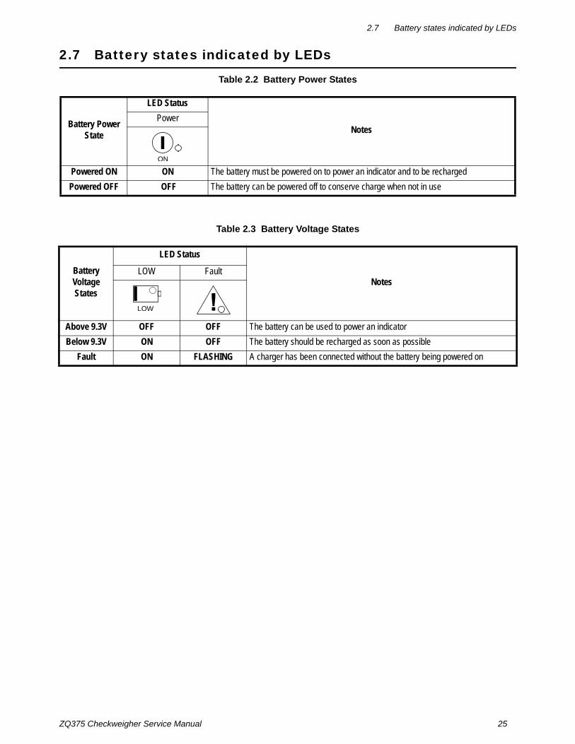
2.7 Battery states indicated by LEDs
2.7 Battery states indicated by LEDs
Table 2.2 Battery Power States
Table 2.3 Battery Voltage States
Battery Power State
LED Status
NotesPower
Powered ON ON The battery must be powered on to power an indicator and to be recharged
Powered OFF OFF The battery can be powered off to conserve charge when not in use
ON
Battery Voltage States
LED Status
NotesLOW Fault
Above 9.3V OFF OFF The battery can be used to power an indicator
Below 9.3V ON OFF The battery should be recharged as soon as possible
Fault ON FLASHING A charger has been connected without the battery being powered on
LOW

26 ZQ375 Checkweigher Service Manual
2 Introduction
Table 2.4 Battery Charging States
2.8 Accessing the menus
Follow these steps to access the various menus in the checkweigher.
1. With the checkweigher powered up and in normal operating mode, press and hold the F1 key …
Pass is briefly displayed, then a flashing 0, prompting you to enter the password.
2. Key in the password for the menu you want to access and press the ZERO key to accept it …
The first item in the top level of the menu you accessed is displayed.
3. Use the navigation keys, shown below, to navigate through the menu structure. The symbols appear on the bottom of the keys.
Battery Charging States
LED Status
NotesCharging Full Fault
Pre-Charge FLASHING OFF OFF The battery is slowly charged for 75 seconds
Fast Charge ON OFF OFFNo faults were found so the battery is now charged quickly
Fully Charged (Wall Charger)
OFF ON OFFThe unit is fully charged and should be disconnected from the power supply
Maintenance Charging (QZ375)
OFF ON OFFThe unit is fully charged and the indicator is simply maintaining the correct voltage
Waiting OFF OFF FLASHINGOver Temp - Battery is hot and needs to cool before charging continues
No Power - The battery circuit has not been turned on
Charging Failure
OFF OFF ON
Battery is above the allowed voltage
Battery has been discharged below 5V
Other failure
CHARGING FULL
You can view the active application name. From the flashing 0 display in the password entry screen. Press F1 and the application name is briefly displayed, then the checkweigher returns to normal operating mode.

ZQ375 Checkweigher Service Manual 27
2.8 Accessing the menus
Menu Navigation Keys:
Press SELECT/ to move down in a menu
Press TARE/ to move up in a menu, except at the
bottom item in a menu, then use ZERO/ or F1
Press PRINT/ to move left in a menu
Press UNITS/ to move right in a menu
Press ZERO/ to accept a value or choice and move up in the menu.
Press F1 to escape and move up in the menu

28 ZQ375 Checkweigher Service Manual
2 Introduction
2.9 Menu annunciators
The menu structure is made up of menu items, parameters, value entry screens and lists from which you choose one item. To help you know where you are in the menu, the bar graph at the top of the display is on while the checkweigher is in the menus and will change appearance according to the following rules:
All segments flashing This means you are in the menu structure but not in any of the following screens.
Center flashing / others solid This means you are in a Quick Code prompt screen. See Quick Code parameter entry on page 32.
Center flashing / others off This means you are in a numeric entry screen. Enter a number and press ZERO to accept.
Right flashing / others off This means you are in a list. Scroll through the choices with the PRINT and UNITS keys and press ZERO to accept.
Left flashing / others off This means you are in a data entry. See String index/character data entry on page 29 for more information.
Every alternate segment flashing This means you are in octet entry for IP, Subnet or Gateway address.

ZQ375 Checkweigher Service Manual 29
2.10 String index/character data entry
2.10 String index/character data entry
Below are guidelines to create or edit text and scale information for print formats. This is a sample of a string entry display.
Left-flashing bar graph segments indicate you are in the String Index select mode. Use the Table 1 key legend to:
l move to the index number you want to editl add a new index numberl delete an existing index number.
After you select the index number, use the Table 2 key actions to edit the character for that index number.
When these segments are flashing, you are in the string index select mode. In this mode you select the index character you want to edit or add/delete a character.
String Indexnumber
Character(ASCII characters
are entered asdecimal values)
Table 1: Key Action When In The String Index Select Mode
Action TARE SELECT ZERO PRINT UNITS F1
Momentary Key PressDeletes current
character
Selects the index character for editing
using the key actions in Table 2
EXITMoves left one position in the
index
Moves right one position in
the indexESC/Abort
Long Key PressDeletes current
character
Append new character after this point
Default character added is 32 (space)
Does nothing
Page Up(Decrements index by 10)
Page Down(Increments index by 10)
Does nothing
Table 2: Key Action When In The Character Edit Mode
Action TARE SELECT ZERO PRINT UNITS F1
Single Key PressIncrements the flashing digit by
1
Decrements the flashing
digit by 1Enter
Delete flashing digit
Add Digit ESC/Abort
Long Key PressMove flashing
digit leftMove flashing
digit rightDoes nothing
Delete the entire entry
Does nothing Does nothing

30 ZQ375 Checkweigher Service Manual
2 Introduction
2.11 Exiting the menus
1. If you are at the bottom item in a menu use ZERO to accept a choice or value and move up a level, or use F1 to escape and move up one level without accepting the choice or value. From that point, press the TARE key repeatedly until …
SAVE no is displayed. This means “Do not save changes. “
2. Use the PRINT or UNITS key to scroll through the choices: SAVE no, SAVEYES and CAnCEL. Press ZERO to accept the displayed choice.
If you choose SAVE no or SAVEYES the checkweigher exits the menu and returns to normal weighing mode.
OR
If you choose CAnCEL, the checkweigher remains in the menu.

ZQ375 Checkweigher Service Manual 31
3 Introduction to the menusMenus, accessed through passwords, are available in the checkweigher to customize and configure the checkweigher for your purposes. The menu levels and their passwords are shown below:
Some menus appear in more than one menu level. As you can see in the table above, the 111 password gives you access to three menus; User, About and Audit. The 3570 password gives you access to those three plus the Diagnostics menu. The 3088 password gives you access to those four plus the Setup menu.
This allows the supervisor to control access to some or all of the menus based on the passwords shared. The menus are the same no matter which menu level you access them from.
See Accessing the menus on page 26 for instructions on how to enter a password to get to the menus. Key functions in the menus are shown below.
Menu Navigation Keys:
Password Menu Level Accessed Menus
111 USER User, About, Audit
3570 DIAGNOSTICS Diag, User, About, Audit
3088 ADMIN Setup, Diag, User, About, Audit
2580 CALIBRATE Calib
1793 SUPER Application specific items. See User manual.
The CALIBRATE menu level accesses the calibration procedure only. You can also access the calibration menu through the Setup menu using the ADMIN password.
The menus are always explained in a sequential manner to cover all information in a logical fashion. You will probably never access all the menu items in this manner. You can navigate to the area of the menu that needs to be changed by using the menu maps and key navigation legends which are inserted as a reminder with most menus.
Press SELECT/ to move down in a menu
Press TARE/ to move up in a menu, except at the
bottom item in a menu, then use ZERO/ or F1
Press PRINT/ to move left in a menu
Press UNITS/ to move right in a menu
Press ZERO/ to accept a value or choice and move up in the menu.
Press F1 to escape and move up in the menu

32 ZQ375 Checkweigher Service Manual
3 Introduction to the menus
3.1 Quick Code parameter entry
The Quick Code parameter entry lets you quickly jump to sections of the menu. Here’s how it works:
1. Access the 3088 ADMIN menu. Press and hold the ZERO key for one second. When you release the key …
P- 0 is displayed.
2. Refer to the Quick Code table in Figure 3.1, find the parameter you want to access, key in that number and press ZERO …
The screen will show the associated menu item.
3. Use the normal procedures to set the menu item and to save the changes you make.
Figure 3.1 Quick Code table
Setup AuditUserDiag About54321
SerialApp. EnetOptionFirmBoot Dload4.1 4.2 4.3 4.4 4.5 4.6 4.7
Site ID SealTime Date3.1 3.2 3.3 3.4
Buttons Ports InputsDisplayScale Options LogsOutputsCur.Zero2.1 2.2 2.3 2.4 2.5 2.6 2.7 2.8 2.9
Calib Scale System Ports Input Output1.1 1.2 1.3 1.4 1.5 1.6
Out 1 Out 2 Out 31.6.1 1.6.2 1.6.3
In 1 In 2 In 31.5.1 1.5.2 1.5.3
E-net Protcl P.F. Edit PLC Printer OptionsInterL FileSerial1.4.1 1.4.2 1.4.3 1.4.4 1.4.5 1.4.6 1.4.7 1.4.8 1.4.9
Port1 Port21.4.1.1 1.4.1.2
Site Display Buttons D-vals Tare Config Archive Serial App Update Passwd
1.3.1 1.3.2 1.3.3 1.3.4 1.3.5 1.3.6 1.3.7 1.3.8 1.3.9 1.3.10 1.3.11
Scale 11.2.1
Capacty Dvision Units Stable AZT Filter Ranges1.2.1.1 1.2.1.2 1.2.1.3 1.2.1.4 1.2.1.5 1.2.1.6 1.2.1.7
Scale 11.1.1
Zero Span Linear Input Gravity Display Cal.Unit Print1.1.1.1 1.1.1.2 1.1.1.3 1.1.1.4 1.1.1.5 1.1.1.6 1.1.1.7 1.1.1.8
Z-Lock
1.3.12

ZQ375 Checkweigher Service Manual 33
3.2 Default Values
3.2 Default Values
Each area of the world has different requirements for checkweigher configuration. The table below shows all the default values listed for all the different sites covered by the checkweigher.
USA GB CAN EU CHINA INDIA
Capacity 5 6 5 6 6 6
Division 0.002 .002 .002 .002 .002 .002
Unit of measure 1 lb kg kg kg kg kg
Unit of Measure 2 off g g g g g
Cal unit lb kg kg kg kg kg
Cal wt 5 6 5 6 6 6
Zero Range 100 2 2 2 2 2
Over Basis Percent Division Percent Division Division Division
Separator decimal decimal decimal comma decimal decimal
Date Format MM-DD-YY DD-MM-YY DD-MM-YY DD-MM-YY DD-MM-YY DD-MM-YY
Time Format 12 Hr 24 24 24 24 24
Average 10 10 10 10 10 10
Filter Constant 1 1 1 1 1 1
Filter Threshold .2 .2 .2 .2 .2 .2
Motion Div. 3 .25 3 3 3 3
Under Cap. Div. 250 20 250 250 250 250
AZT Div. 1 .25 .5 .5 .5 .5
App Sim375 Mid375 Sim375 Mid375 Sim375 Sim375

34 ZQ375 Checkweigher Service Manual
4 User level menus
4 User level menusThe USER level (password 111) contains the User, About, and Audit menus arranged as shown in Figure 4.1.
Figure 4.1 USER level (password 111) menus
4.1 User menu
The User menu is shown in Figure 4.2.
Figure 4.2 User menu
User About AuditSee
page 34See
page 38See
page 42
NormalWeighing Mode
Press andhold F1 key
Enter 111& press ZERO
SELECT =
TARE =
PRINT =
UNITS =
ZERO =
F1 = Escape or
User
Site ID SealTime Date
Set Style
h- m- s-
12hr 12hr-AP 24hr
Set Style
y- m- d-
MMDD4YMMDD2Y DDMM2Y DDMM4Y
Reference Accessingthe menus onpage 26
EnterSite ID
View Seal
Status
SELECT =
TARE =
PRINT =
UNITS =
ZERO =
F1 = Escape or

ZQ375 Checkweigher Service Manual 35
4.1 User menu
Use this menu to set the time, date, site ID, and to see the physical seal status. Each is explained below:
4.1.1 Time
User Time
1. Access the User menu and press SELECT …
tiME is displayed. Use this to set the time and clock style.
Set time
Time Set
2. Press SELECT …
SEt is displayed.
3. Press SELECT …
h- x is displayed, with the x flashing. This is a numeric entry screen for the hour value.
4. Use the Numeric entry procedure on page 20 and key in the hour of the day using military (24 hr) time and press ZERO …
The choice is made and M- x is displayed, with the x flashing. This is a numeric entry screen for the minute value.
5. Key in the minute value and press ZERO …
The choice is made and S- x is displayed, with the x flashing. This is a numeric entry screen for the second value.
6. Key in the seconds value and press ZERO …
The choice is made and SEt is displayed.
Style
Time Set Style
7. Press UNITS …
StYLE is displayed. Use this to set the style of clock for printouts. Choices are 12hr, 12hr-AP (AM/PM) and 24hr (military time).
8. Press SELECT …
12hr is displayed.
The and symbols stand for direction moved in the menu. So User Time illustrates that you move down from User to Time. This will help you keep track of where you are in the menu strucutre.

36 ZQ375 Checkweigher Service Manual
4 User level menus
9. Press PRINT or UNITS to scroll through the choices. Press ZERO when your choice is displayed …
The choice is made and StYLE is displayed.
10. Press TARE …
tiME is displayed.
4.1.2 Date
User Time Date
1. Press UNITS to move to the next menu item …
dAtE is displayed.
Set date
Date Set
2. Press SELECT …
SEt is displayed.
3. Press SELECT …
y- x is displayed, with the x flashing. This is a numeric entry screen for the year value.
4. Use the Numeric entry procedure on page 20 and key in the year and press ZERO …
The choice is made and M- x is displayed, with the x flashing. This is a numeric entry screen for the month.
5. Key in the month value and press ZERO …
The choice is made and d- x is displayed, with the x flashing. This is a numeric entry screen for the day value.
6. Key in the day value and press ZERO …
The choice is made and SEt is displayed.
Style
Date Set Style
7. Press UNITS to move to the next menu item …
StYLE is displayed. Use this to set the style of date for printouts. Choices are MMDD2Y, MMDD4Y, DDMM2Y and DDMM4Y.
8. Press SELECT …
MMDD2Y is displayed.
9. Press PRINT or UNITS to scroll through the choices. Press ZERO when your choice is displayed …
The choice is made and StYLE is displayed.

ZQ375 Checkweigher Service Manual 37
4.1 User menu
10. Press TARE …
dAtE is displayed.
4.1.3 Site ID
User Time Date Site ID
1. From dAtE, press UNITS to move to the next menu item …
SitE id is displayed. Use this item to enter a site ID number or checkweigher location reference number (up to six characters).
2. Press SELECT …
A string entry screen is displayed. Refer to String index/character data entry on page 29
3. Key in the site ID number on the numeric keypad and press ZERO to accept …
SitE id is displayed.
4.1.4 Seal
User Time Date Site ID Seal
1. From SitE id, press UNITS …
SEAL is displayed.
2. Press SELECT …
no SEAL or SEALEd is displayed. This is the status of the physical seal jumper inside the checkweigher. If the unit is sealed, no changes can be made to the configuration of the checkweigher.
3. Press F1 to return to the SEAL display.
4. To exit the menu, see Exiting the menus on page 30.
The Site ID can be used in transmitted or printed information.
The seal jumper, P9, is located near the top left corner of the main PCB. If the jumper is installed, the checkweigher is sealed. This means the ADMIN and CALIB menus cannot be accessed and the display will flash SEALEd. Only Time and Date can be changed when the indicator is Sealed.

38 ZQ375 Checkweigher Service Manual
4 User level menus
4.2 About menu
The About menu is shown in Figure 4.3.
Figure 4.3 About menu
Use this menu to display information about the various items shown in Figure 4.3. Each is explained below:
4.2.1 Bootloader
About Boot
1. Access the About menu and press SELECT …
boot is displayed.
2. Press SELECT …
PArtno is displayed
Serial
About
App. EnetOptionFirmBoot
VersionPartno
IP GatewaySubnet
VersionPartno
VersionPartno
Version
Mac
Dload
Sserial Dserial
Type
Reference Accessing the menus on page 26
Displays the bootloader
PN
Displays the bootloaderversion #
Displays the firmware
part number
Displays the firmware
version number
Displays the application
part number
Displays the application
version number
ViewSerial
Number
DisplaysIP address
DisplaysSubnet
info
DisplaysGateway
info
DisplaysMacinfo
SELECT =
TARE =
PRINT =
UNITS =
ZERO =
F1 = Escape or
Definitions:Bootloader Software that makes the electronics run.
Firmware Embedded system software that creates core functions of the product.
App Specific software to create specific behavior for a given installation. For example: counting, accumulation, peak, etc.

ZQ375 Checkweigher Service Manual 39
4.2 About menu
3. Press SELECT …
The bootloader part number is displayed.
4. Press ZERO to return to the PArtno item.
5. Press UNITS …
VErSion is displayed.
6. Press SELECT …
The version number of the bootloader is displayed.
7. Press ZERO to return to the VErSion item.
8. Press TARE to return to the boot item.
4.2.2 Firmware and Application
About Boot Firmware and Application
1. From boot, press UNITS to move to the next item …
FirM is displayed. This stands for firmware.
2. Repeat the same pattern of key presses in steps 2 through 8 above to view the part number and version for the FirM (firmware) and APP (application) menu items.
4.2.3 Serial
About Boot Firmware Application Serial
1. With APP displayed, press UNITS to move to the next item in this level …
SEriAL is displayed.
2. Press SELECT …
The checkweigher’s serial number is displayed.
3. Press TARE to return to the SEriAL display.
4.2.4 Option
About Boot Firmware Application Serial Option
1. From SEriAL, press UNITS to move to the next item in this level …
oPtion is displayed. Use this to view the version and type of installed option module.
The Serial Number should match the serial number that is printed on the indicator ID tag and is also included in the printed calibration report.

40 ZQ375 Checkweigher Service Manual
4 User level menus
2. Press SELECT …
VErSion is displayed.
3. Press SELECT to see the version of the installed option module …
The version is displayed. If there is no installed option module, cAnt is displayed.
4. Press ZERO …
VErSion is displayed.
5. Press UNITS to move to the next item …
tYPE is displayed.
6. Press SELECT to see the type of the installed option module …
The type of module is displayed. If there is no installed option module, cAnt is displayed.
7. Press ZERO …
tYPE is displayed.
8. Press TARE …
oPtion is displayed.
4.2.5 Enet
About Boot Firmware Application Serial Option Enet
1. From oPtion, press UNITS to move to the next menu item …
EnEt is displayed. Use this item to view the values for the IP, Subnet, Gateway and MAC addresses.
IP
Enet IP
2. Press SELECT …
iP is displayed. Use this item to view the four part IP address.
3. Press SELECT …
0 xxx is displayed. This is first octet of the IP address
4. Press ZERO …
1 xxx is displayed. This is second octet of the IP address.
If the indicator is connected to an ethernet network, the values displayed will be the current assigned addresses.

ZQ375 Checkweigher Service Manual 41
4.2 About menu
5. Press ZERO …
2 xxx is displayed. This is third octet of the IP address.
6. Press ZERO …
3 xxx is displayed. This is fourth octet of the IP address.
7. Press ZERO …
iP is displayed.
MAC
Enet IP Subnet & Gateway & MAC
8. Press UNITS …
Subnet is displayed.
9. Repeat this sequence of key presses for the Subnet, Gateway and MAC addresses.
10. When you are finished, press TARE to return to the Enet menu item.
4.2.6 Download
About Boot Firmware Application Serial Option Enet Dload
1. Press UNITS …
dLoAd is displayed. This stands for download. Under SSEriAL you can view the serial number of the software application that created the configuration file. Under dSEriAL you can view the serial number of the software application that downloaded the configuration file. This is used for security and licensing purposes.
Sserial
Dload Sserial
2. Press SELECT …
SSEriAL is displayed.
3. Press SELECT …
The 1st half of the serial number of the creating application of the configuration file is displayed.
4. Press ZERO to show the 2nd half.
5. Press F1 …
SSEriAL is displayed.
If the license number of your Configuration Software application does not match either the SSerial or DSerial numbers you will be unable to upload the existing configuration file from the indicator. Contact AWTX Technical Support for assistance.

42 ZQ375 Checkweigher Service Manual
4 User level menus
Dserial
Dload Sserial Dserial
6. Press UNITS …
dSEriAL is displayed.
7. Press SELECT …
The 1st half of the serial number of the downloading application of the configuration file was downloaded to, is displayed.
8. Press ZERO to show the 2nd half.
9. Press F1 …
dSEriAL is displayed.
10. Press TARE twice …
About is displayed.
11. To exit the menu, see Exiting the menus on page 30.
4.3 Audit menu
The Audit menu is shown in Figure 4.4.
Figure 4.4 Audit menu
Use this menu to display audit counters for configuration and calibration and to print the information. Each is explained below:
4.3.1 Counter
Audit Counter
1. Access the Audit menu and press SELECT …
countEr is displayed. This has two counters that tell you how many times the checkweigher has been configured and calibrated.
Audit
PrintCounter
Config Calib
Port 1 Port 2 USB
Reference Accessing the menus on page 26
SELECT =
TARE =
PRINT =
UNITS =
ZERO =
F1 = Escape or Displaysnumber of
configurations
Displaysnumber of
calibrations

ZQ375 Checkweigher Service Manual 43
4.3 Audit menu
Config
Counter Config
2. Press SELECT …
conFig is displayed.
3. Press SELECT again …
A number appears showing how many times the checkweigher has been configured.
4. Press ZERO …
conFig is displayed.
Calibration
Counter Config Calib
5. Press UNITS to move to the next item in this level …
cALib is displayed.
6. Press SELECT …
A number appears showing how many times the checkweigher has been calibrated.
7. Press ZERO …
cALib is displayed.
8. Press TARE …
countEr is displayed.
4.3.2 Print
Audit Counter Print
1. Press UNITS …
Print is displayed.
Port 1/Port 2/USB
Print Port 1 Port 2 USB
2. Press SELECT …
Port1 is displayed. This is the first of three choices: Port 1, Port 2 or uSb. Use these to select which port to print the audit report through.
Printing to USB requires that a USB flash drive is connected to the indicator host USB. Printing to USB will create a folder on the flash drive and a comma separated file with the data.

44 ZQ375 Checkweigher Service Manual
4 User level menus
3. Press PRINT or UNITS to scroll through the choices and press ZERO when your choice is displayed …
Print is displayed.
4. To exit the menu, see Exiting the menus on page 30.

ZQ375 Checkweigher Service Manual 45
5.1 Diag menu
5 Diagnostics level menusThe DIAGNOSTICS level (password 3570) is the same as the USER level except it adds the Diag menu. The DIAGNOSTICS level is shown in Figure 5.1.
Figure 5.1 DIAGNOSTICS level (password 3570) menus
5.1 Diag menu
Use the Diag menu to check or verify the performance of the checkweigher. The diagnostic tests available include: Scale A to D to view output from the connected scale base or load device, the current zero offset from calibration zero, a display segment test, a front panel keypad or button test, serial Com ports and USB host port test, remote inputs and outputs test, and an option module test if installed. You can print an error log report that provides information on previous error conditions such as overloads or underloads. The Diag menu is shown in Figure 5.2.
Figure 5.2 Diag menu
Each of the items in the Diag menu is explained below:
Diag User About AuditSee page 34 See page 38 See page 42See page 45
The and symbols stand for direction moved in the menu. So Diag Scale illustrates that you move down from Diag to Scale. This will help you keep track of where you are in the menu structure.
Reference Accessing the menus on page 26
Diag
Buttons Ports InputsDisplayScale Options LogsOutputs
Port1 Port2 USB
Print Clear
Cur.Zero
Value Clear
1 2 3Viewscale output
in A to D
Continuousdisplay
test
Testbutton
function(ZERO exits
the test)
Testconfigured
inputs Togglesselected output
on and off
Test installedoptions
Loopbacktest
Performswrite/read
test
Loopbacktest
SELECT =
TARE =
PRINT =
UNITS =
ZERO =
F1 = Escape or
46 ZQ375 Checkweigher Service Manual
5 Diagnostics level menus
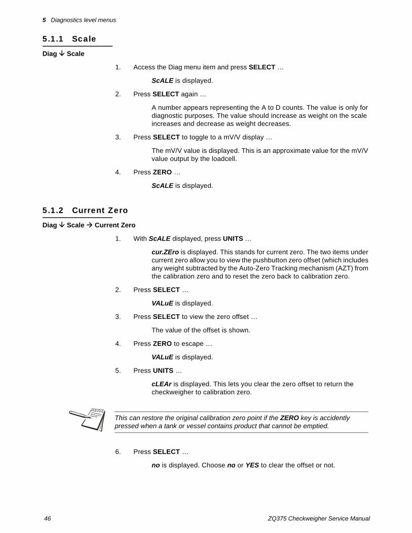
5.1.1 Scale
Diag Scale
1. Access the Diag menu item and press SELECT …
ScALE is displayed.
2. Press SELECT again …
A number appears representing the A to D counts. The value is only for diagnostic purposes. The value should increase as weight on the scale increases and decrease as weight decreases.
3. Press SELECT to toggle to a mV/V display …
The mV/V value is displayed. This is an approximate value for the mV/V value output by the loadcell.
4. Press ZERO …
ScALE is displayed.
5.1.2 Current Zero
Diag Scale Current Zero
1. With ScALE displayed, press UNITS …
cur.ZEro is displayed. This stands for current zero. The two items under current zero allow you to view the pushbutton zero offset (which includes any weight subtracted by the Auto-Zero Tracking mechanism (AZT) from the calibration zero and to reset the zero back to calibration zero.
2. Press SELECT …
VALuE is displayed.
3. Press SELECT to view the zero offset …
The value of the offset is shown.
4. Press ZERO to escape …
VALuE is displayed.
5. Press UNITS …
cLEAr is displayed. This lets you clear the zero offset to return the checkweigher to calibration zero.
6. Press SELECT …
no is displayed. Choose no or YES to clear the offset or not.
This can restore the original calibration zero point if the ZERO key is accidently pressed when a tank or vessel contains product that cannot be emptied.

ZQ375 Checkweigher Service Manual 47
5.1 Diag menu
7. Press UNITS to toggle between the two choices and press ZERO when your choice is displayed …
If you choose YES, the offset is cleared and cLEAr is displayed. If you choose no, the offset is not cleared and cLEAr is displayed.
8. Press TARE …
cur.ZEro is displayed.
5.1.3 Display
Diag Scale Current Zero Display
1. With cur.ZEro displayed, press UNITS …
diSPLAy is displayed.
2. Press SELECT …
The segments of the display light up in progression and continue until you press any key.
After you press any key, diSPLAy is displayed.
5.1.4 Buttons
Diag Scale Current Zero Display Buttons
1. With diSPLAy displayed, press UNITS …
buttonS is displayed.
2. Press SELECT …
tESting is briefly displayed followed by dashes.
3. Press any key to test if it is functioning and its name or value will be displayed. Press ZERO to escape the test.
ZERO is briefly displayed then buttonS.
5.1.5 Ports
Diag Scale Current Zero Display Buttons Ports
1. With buttonS displayed, press UNITS …
PortS is displayed.
2. Press SELECT …
Port 1 is displayed. Use this to do a loopback test on port 1.

48 ZQ375 Checkweigher Service Manual
5 Diagnostics level menus
3. Press SELECT to test this port …
tESting is briefly displayed and then PASS or FAiL, depending on if the send and receive lines are jumpered (pass) or not (fail). Add a jumper or wire between the transmit output and receive input. On an external 9 pin connector the transmit line is pin 2 and the receive line is pin 3.
The PASS or FAiL is displayed briefly and Port 1 is displayed.
4. Press UNITS to advance to the next item …
Port 2 is displayed. Use this to do a loopback test on port 2.
5. Press SELECT to test this port …
tESting is briefly displayed and then PASS or FAiL, depending on if the transmit and receive lines are jumpered (pass) or not (fail).
The PASS or FAiL is displayed briefly and Port 2 is displayed.
6. Press UNITS to advance to the next item …
uSb is displayed. Use this to test a connected USB flash drive.
7. Press SELECT to test …
oPEn is briefly displayed, then WritE is briefly displayed, then rEAd is briefly displayed, then PASS or FAiL, depending on if the USB device is working correctly or not. The PASS or FAiL is displayed briefly and uSb is displayed.
If no USB device is plugged in when you begin the test, oPEn is briefly displayed, then no uSb is briefly displayed, then uSb.
8. From the uSb display, press TARE …
PortS is displayed.
5.1.6 Inputs
Diag Scale Current Zero Display Buttons Ports Inputs
1. With PortS displayed, press UNITS …
inPutS is displayed.
2. Press SELECT …
in 000 is displayed, if no inputs are jumpered.
It is recommended that you insert the jumper (a paper clip works) into the external cable connector to validate the wiring and not just the internal ports. See System block diagram on page 172 for I/O configuration of the serial ports TB3.
The input test is used to verify if external switches wired to the input ports on TB2 are functioning properly.

ZQ375 Checkweigher Service Manual 49
5.1 Diag menu
3. To test input 1, jumper pins 1 and 2 of the I/O connector on the checkweigher …
The first digit becomes 1 until the jumper is removed.
4. To test input 2, jumper pins 1 and 3 of the I/O connector on the checkweigher …
The second digit becomes 2 until the jumper is removed.
5. To test input 3, jumper pins 1 and 4 of the I/O connector on the checkweigher ….
The third digit becomes 3 until the jumper is removed.
6. Press ZERO …
inPutS is displayed.
5.1.7 Outputs
Diag Scale Current Zero Display Buttons Ports Inputs Outputs
1. With inPutS displayed, press UNITS …
outPutS is displayed.
2. Press SELECT …
outPut1 is displayed.
3. Press SELECT …
o.1-oFF is displayed.
4. Press PRINT or UNITS to toggle the output on (o.1-on) and repeat to turn it oFF.
Output 1 will be toggled on and off as you press the keys. This is shown by the annunciator (SP1) on the display turning on and off.
5. Press ZERO or F1 to stop the test …
outPut1 is displayed.
6. Press UNITS to go to the next output. Repeat the steps to test output 2 and 3.
7. When finished, press TARE …
outPutS is displayed.
The output test is used to verify if external relays or lights (etc.) connected to TB2 are properly wired and functioning properly.
CAUTION: Be sure to take proper precautions to ensure material controlled by the scale outputs will not create a hazardous condition during an output test.
50 ZQ375 Checkweigher Service Manual
5 Diagnostics level menus
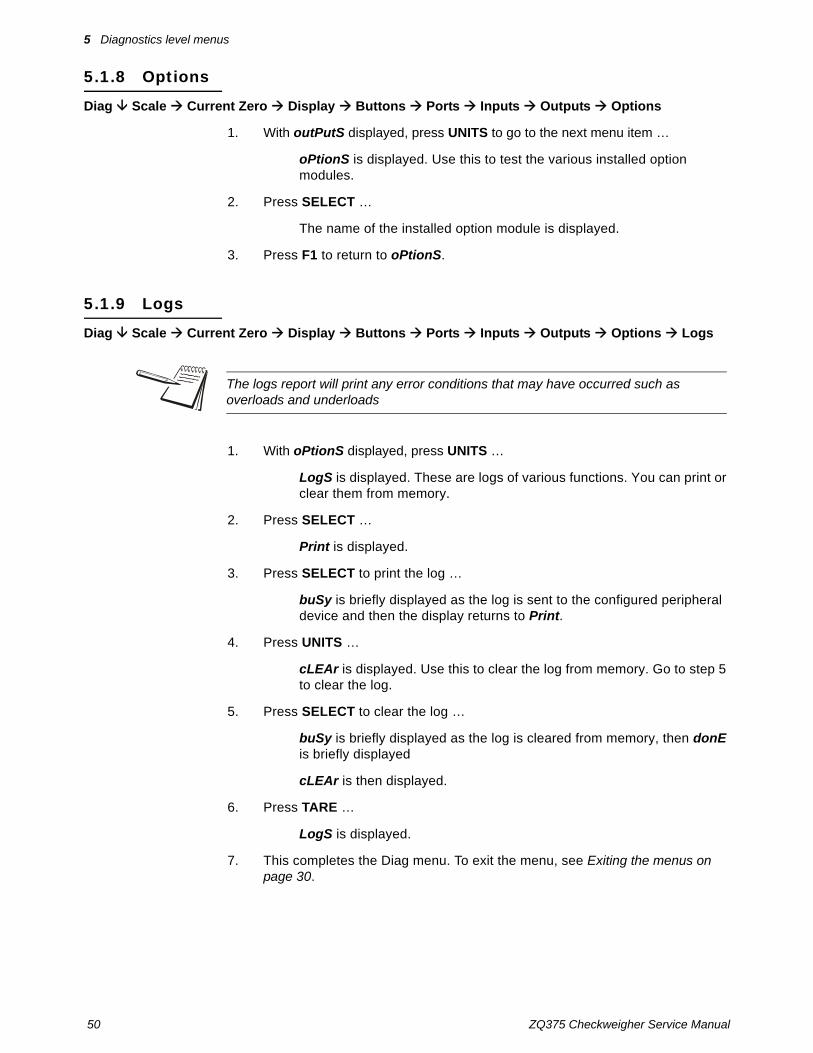
5.1.8 Options
Diag Scale Current Zero Display Buttons Ports Inputs Outputs Options
1. With outPutS displayed, press UNITS to go to the next menu item …
oPtionS is displayed. Use this to test the various installed option modules.
2. Press SELECT …
The name of the installed option module is displayed.
3. Press F1 to return to oPtionS.
5.1.9 Logs
Diag Scale Current Zero Display Buttons Ports Inputs Outputs Options Logs
1. With oPtionS displayed, press UNITS …
LogS is displayed. These are logs of various functions. You can print or clear them from memory.
2. Press SELECT …
Print is displayed.
3. Press SELECT to print the log …
buSy is briefly displayed as the log is sent to the configured peripheral device and then the display returns to Print.
4. Press UNITS …
cLEAr is displayed. Use this to clear the log from memory. Go to step 5 to clear the log.
5. Press SELECT to clear the log …
buSy is briefly displayed as the log is cleared from memory, then donE is briefly displayed
cLEAr is then displayed.
6. Press TARE …
LogS is displayed.
7. This completes the Diag menu. To exit the menu, see Exiting the menus on page 30.
The logs report will print any error conditions that may have occurred such as overloads and underloads

ZQ375 Checkweigher Service Manual 51
6.1 Setup menu
6 ADMIN level menusThe ADMIN level (password 3088) is the same as the DIAG level except it adds the Setup menu. The ADMIN level is shown in Figure 6.1.
Figure 6.1 ADMIN level
6.1 Setup menu
In the Setup menu there are various submenus available to configure specific sections of the scale operation. The top level items in the Setup menu are shown in Figure 6.2.
Figure 6.2 Setup menu (password 3088)
Each of the items in the Setup menu are explained in the following sections.
Setup Diag User About Audit
See page 34 See page 38 See page 42See page 45See page 51
Setup
Calib Scale System Ports Input Output
See page 52 See page 60 See page 70 See page 83 See page 107 See page 108

52 ZQ375 Checkweigher Service Manual
6 ADMIN level menus
6.2 Calibration Procedure
Use the Calib menu to perform Zero and Span calibration, add Linearity correction points, manually input calibration parameters for Zero and Span, manually input Gravitational correction values, view the live weight, set the calibration unit of measure and print out a calibration report. Follow the menu in Figure 6.3 and the steps that follow.
Figure 6.3 Calibrate menu
The calibration procedure can be accessed directly following this procedure:
The and symbols stand for direction moved in the menu. So Calib Scale 1 illustrates that you move down from Calib to Scale 1. This will help you keep track of where you are in the menu structure.
Calib
Zero Span Linear Input Gravity Display Cal.Unit
LB 1000g
Pt2 Pt3 Pt4
LastCal.Zero Temp
Zero Span
Counts mV
Counts mV
XXXX
XXXX
c xxxxG-fact Lat Alt Calc
Port 1 Port 2 USB
Scale 1
Reference Accessing the menus on page 26
Viewlive scale
weight
SELECT =
TARE =
PRINT =
UNITS =
ZERO =
F1 = Escape or

ZQ375 Checkweigher Service Manual 53
6.2 Calibration Procedure
6.2.1 Accessing calibration
Calib Scale 1
1. Press and hold F1 …
Pass is briefly displayed, then a flashing 0, prompting you to enter the password.
2. Use the Numeric entry procedure on page 20 and key in the password, 2580, and press ZERO to accept it …
cALib is displayed.
3. Press SELECT …
ScALE 1 is displayed. There is only one scale available to calibrate so continue to the next step.
6.2.2 Zero Procedure
Calib Scale 1 Zero
1. From ScALE 1 press SELECT …
ZEro is displayed.
2. Press SELECT again …
cAL.ZEro is displayed. Use this to record the zero point.
3. To perform a normal calibration, from the cAL.Zero display, press SELECT …
c xxxx is displayed. The c denotes the fact you are in the calibration procedure. The numeric value is the current weight value seen by the checkweigher.
4. Remove all weight from the scale and press ZERO …
buSy is briefly displayed and then c 0 is displayed, if the zero procedure was successful. If not successful, repeat steps 3 and 4.
5. Press ZERO …
cAL.ZEro is displayed.
6.2.3 Span Procedure
Calib Scale 1 Zero Span
1. From cAL.ZEro display, press TARE …
Zero is displayed.
On the initial zero calibration of the checkweigher to a new scale, the zero cal counts by appear unstable. Continue to the span calibration and when completed the condition should correct itself.

54 ZQ375 Checkweigher Service Manual
6 ADMIN level menus
2. Press UNITS …
SPAn is displayed.
3. Press SELECT to span the scale …
XXXX is displayed with a flashing right digit.
4. Press ZERO to accept the displayed span weight or use the Numeric entry procedure on page 20 and key in your span weight (not to exceed the configured capacity) and press ZERO …
c xxx is displayed. This is the current weight on the scale. The c is a reminder that you are in the calibration procedure.
5. Place the span weight on the scale and press ZERO …
buSy is briefly displayed and then c XXXX is displayed, which should be the same as the span weight you keyed in. The span procedure is complete.
6. Press ZERO …
SPAn is displayed.
6.2.4 Alternate zero procedures
Last Zero and Temporary Zero
As you can see in the Calibrate menu there are two other items under Zero; Last and Temp.
Last Use Last zero if certified test weights placed on the scale display a slightly inaccurate value. Be sure that the scale is at zero before the test weights are added and enter the calibration procedure and select Last zero. The last acquired zero value will be assigned as the new Cal Zero value. Continue to the SPAN procedure without removing the test weights. Key in the value of the test weights on the scale and complete the SPAN procedure. The test weights will now read accurately.
Temp. Use Temp. zero when the product weight on the scale, such as in a tank or vessel, appears to be inaccurate but cannot be removed to establish a no-load condition. Enter the calibration procedure and select Temp. zero. The current weight on the scale will be temporarily assigned as the Cal Zero value. Continue to the SPAN procedure, key in the value of the test weights and place them on the scale and complete the SPAN procedure. The original Cal Zero is restored after exiting the span procedure and the current product weight will now be correctly represented. Due to factors that created the original inaccuracy, it may be necessary to re-zero the scale when the tank or vessel is empty.
To save calibration or any changes you make in the menus, when you are finished making the changes, press TARE or F1 repeatedly until the display shows SAVE no. Press UNITS and SAVE YES is displayed. Press ZERO to accept this. All changes will be saved and the checkweigher will return to normal weighing mode.

ZQ375 Checkweigher Service Manual 55
6.2 Calibration Procedure
With Last or Temp zero displayed, press SELECT …
buSY and donE are briefly displayed, followed by Last or Temp depending on which procedure you are performing.
7. Press TARE …
ZEro is displayed.
8. Press UNITS …
SPAn is displayed.
9. Continue the regular span procedure.
6.2.5 Linearity Procedure
Calib Scale 1 Zero Span Linear
1. From SPAn, press UNITS …
LinEAr is displayed. Linearity allows you to add up to three linearization points for the scale. The points are numbered 2, 3 and 4 because, internally, the zero reference point is point 1 and the span point is point 5.
2. With LinEAr displayed, press SELECT …
Pt2 is displayed.
3. Press ZERO …
A flashing 0 is displayed. This is the screen for entering the point 2 test weight.
4. Use the Numeric entry procedure on page 20 and key in a value for the weight and press ZERO …
c xxx is displayed. This is the live weight on the scale.
5. Place the test weight, equal to the value keyed in during step 4 above, on the scale and press ZERO …
buSy is briefly displayed and then c xxx is displayed again.
6. Press ZERO …
Pt2 is displayed. This completes the setting of linearization point 2.
7. Repeat steps 3 through 6 for points 3 and 4, if necessary.
8. Press TARE …
LinEAr is displayed.
Perform the linearity procedure only if test weights applied to the scale between the zero and span calibration points are showing slight inaccuracies, such as ± a few divisions. If large inaccuracies are recorded, this indicates a possible mechanical problem or possible loadcell failure which linearity calibration may not be able to correct.

56 ZQ375 Checkweigher Service Manual
6 ADMIN level menus
6.2.6 Input Calibration Procedure
Calib Scale 1 Zero Span Linear Input
1. From LinEAr press UNITS …
inPut is displayed. This menu item allows you to enter calibration data recorded from an earlier calibration procedure using the numeric keypad.
Zero
Input Zero
2. Press SELECT …
ZEro is displayed. This is for entering a value for zero in either ADC counts or mv/V.
3. Press SELECT …
countS is displayed. Use this to enter a zero point using ADC counts or press UNITS to toggle to mV if you want to set the zero point using mV/V.
4. With countS or mV displayed, press ZERO to access the value entry screen.
5. Use the Numeric entry procedure on page 20 and key in the count value or the mV/V (millivolts per volt) value you want for the zero point and press ZERO to accept it …
ZEro is displayed.
Span
Input Zero Span
6. Press UNITS …
SPAn is displayed.
7. Press SELECT …
A flashing value is displayed representing the span weight.
8. Press ZERO to accept this or use the Numeric entry procedure on page 20 and key in the span weight that corresponds with the span ADC or mV/V value and press ZERO to accept it …
countS is displayed. Use this to enter a span using ADC counts or press UNITS to scroll to mV if you want to set the span using mV/V.
9. With countS or mV displayed, press ZERO to access the value entry screen.
Input calibration is useful to restore an checkweigher back to previous calibration settings if inadvertently changed or to clone a replacement ZQ375 checkweigher.
Current settings for zero and span values can be obtained from a printed calibration report. See Print calibration report on page 59.

ZQ375 Checkweigher Service Manual 57
6.2 Calibration Procedure
10. Use the Numeric entry procedure on page 20 and key in the count value or the mV/V value you want for the span and press ZERO to accept it …
SPAn is displayed.
11. Press TARE …
inPut is displayed.
6.2.7 Gravity Factor Procedure
Calib Scale 1 Zero Span Linear Input Gravity
1. From inPut press UNITS …
grAvitY is displayed. Use this item to key in a gravity constant value. If the scale has been calibrated at a different location that has a significantly different gravitational factor than the installation site, and it is not possible to re-calibrate with known test weights, the scale can be adjusted using this gravity factor.
Gravity factor
Gravity G-Fact
2. To set the gravity factor, press SELECT …
g-FACt is displayed.
3. If you know the local gravitation factor (allowable range is 9.70000 to 9.90000) and want to key it in, proceed to step 4.ORIf you do not know the local gravitation factor but can determine the approximate latitude and altitude of the installation site, then the checkweigher can calculate the gravity factor from these two values. Skip to step .
4. Press SELECT …
The current setting for the gravity factor is displayed.
5. Use the Numeric entry procedure on page 20 and key in the new gravitation factor and press ZERO …
The value is accepted and the display returns to g-FACt. Proceed to step 14.
Latitude
Gravity G-Fact Lat
6. From the g-FACt display, press UNITS …
LAt is displayed. This stands for latitude.
7. Press SELECT …
A value entry screen appears.

58 ZQ375 Checkweigher Service Manual
6 ADMIN level menus
8. Use the Numeric entry procedure on page 20 and key in the latitude for the installation site. The valid range is 0 to 90. A positive value works for north or south of the equator. Press ZERO to accept it …
LAt is displayed.
Altitude
Gravity G-Fact Lat Alt
9. Press UNITS …
ALt is displayed. This stands for altitude.
10. Press SELECT …
A value entry screen appears.
11. Use the Numeric entry procedure on page 20 and key in the altitude for the installation site. The valid range is 0 to 30,000 ft. (10000 m). Press ZERO to accept it …
ALt is displayed.
Calculate gravity factor
Gravity G-Fact Lat Alt Calc
12. After you have entered the latitude and altitude values, press UNITS …
CALC is displayed. This stands for calculate.
13. Press SELECT …
buSY is displayed while the checkweigher calculates the gravity factor and loads this value as the gravity factor. CALC is then displayed. Be sure to save the changes when you exit the menu and test the accuracy with a know weight.
14. Press TARE …
grAvitY is displayed.
6.2.8 Display
Calib Scale 1 Zero Span Linear Input Gravity Display
1. From grAvitY press UNITS …
diSPLAY is displayed. Use this item to view live scale weight while in the calibration menu.
CAUTION: Verify with local agencies if adjusting the gravity factor is accepted in your area. It may be required that calibration be done with certified weights.

ZQ375 Checkweigher Service Manual 59
6.2 Calibration Procedure
2. Press ZERO to view the live weight …
The live weight value is displayed.
3. Press F1 …
diSPLAY is displayed.
6.2.9 Calibration Unit
Calib Scale 1 Zero Span Linear Input Gravity Display Cal.Unit
1. From diSPLAY press UNITS …
CAL.unit is displayed. This stands for calibration unit. This is the unit of measure of the weights used during calibration.
2. Press SELECT …
Lb or 1000g is displayed.
3. Use PRINT or UNITS to toggle between the choices and press ZERO to accept the displayed choice.
CAL.unit is displayed.
6.2.10 Print calibration report
Calib Scale 1 Zero Span Linear Input Gravity Display Cal.Unit Print
1. From CAL.unit press UNITS …
Print is displayed. Use this print function to print a calibration report through Port 1, Port 2 or to USB. This information can be used in the future to restore calibration.
2. Press SELECT …
Port 1 is displayed.
3. Use PRINT or UNITS to scroll through the choices and press ZERO to accept the displayed choice.
The calibration report will be printed to a peripheral device through the chosen port.
4. Press TARE twice to return to the cALib item.
5. This completes the Calib menu. To exit the menu, see Exiting the menus on page 30.
Use the ZERO key to zero the checkweigher so you can add test weights to validate the accuracy of the scale.

60 ZQ375 Checkweigher Service Manual
6 ADMIN level menus
6.3 Scale
Use the Scale menu to configure the scale operating parameters such as capacity and division size, available units of measure, motion and auto zero tracking values, filtering parameters, range of operation for zeroing the scale, over and underload conditions and the return to gross zero region or band. Refer to the menu in Figure 6.3 and the steps that follow.
Figure 6.4 Scale menu
Access the Scale menu. See Accessing the menus on page 26.
CAUTION: Be sure you follow all local weights and measures regulations.
Some parameters may be set automatically by your choice of SitE in the System menu item.
Scale
Capacty Dvision Units Stable AZT Filter Ranges
0-rnge O-cap G-zero
Avg Const T-hold
Div Time
Div Time
Unit 1 Unit 2 Unit 3 Unit 4
Lb 1000 g Oz Gr Lb-oz
0.000001 0.000002 0.000005 100 200 500
Ratio String
Unit Custom
Cust 1 OffCust 2 Cust 3
Cust 1 Cust 2 Cust 3
Basis
Percent Div
O-Load U-Load
Scale 1
Reference Accessing the menus on page 26
Key inscale capacity
Key in % of scale capacity
Key in 0 to10000 div.
Key in valuebased on
Basischosen
Not forUnit 1
to
SELECT =
TARE =
PRINT =
UNITS =
ZERO =
F1 = Escape or

ZQ375 Checkweigher Service Manual 61
6.3 Scale
6.3.1 Accessing scale configuration
Scale Scale 1
With Scale displayed, press SELECT …
ScALE 1 is displayed. There is only one scale available so continue to Capacity.
6.3.2 Capacity
Scale Scale 1 Capacty
1. From ScALE 1 press SELECT …
A value is shown on the screen with the right digit flashing. This is the current setting for the capacity of the scale.
2. Press ZERO to accept this or key in a new value and press ZERO …
cAPActY is displayed.
6.3.3 Division
Scale Scale 1 Capacty Dvision
1. From cAPActY press UNITS …
dViSion is displayed. This stands for division size.
2. Press SELECT …
The current division size is displayed.
3. Press PRINT or UNITS to scroll through the division size choices. Choices are 0.000001, 0.000002, 0.000005, 0.00001, 0.00002, 0.00005, 0.0001, 0.0002, 0.0005, 0.001, 0.002, 0.005, 0.01, 0.02, 0.05, 0.1, 0.2, 0.5, 1, 2, 5, 10, 20, 50, 100, 200 and 500. The default value is 1. Press ZERO to accept the displayed choice.
dViSion is displayed.
The capacity that you enter should never exceed the rated capacity of the scale that is connected.
Division sizes for other units of measure are automatically calculated by the checkweigher.

62 ZQ375 Checkweigher Service Manual
6 ADMIN level menus
6.3.4 Units
Scale Scale 1 Capacty Dvision Units
1. From dViSion press UNITS …
unitS is displayed.
Unit
Units Unit
2. Press SELECT …
unit is displayed. From this item you can choose which units of measure are available when the user presses the UNITS key during normal weighing. You can have up to four units for viewing. They are listed as: unit 1, unit 2, unit 3 and unit 4. You can assign any of the following units of measure to any of these: lb, 1000g, oz, gr, lb-oz, cuSt 1, cuSt 2, cuSt 3, cuSt 4 or oFF.
cuSt stands for custom unit. To use a custom unit you must first create them by entering a ratio and a string to define it. See the section below on creating a custom unit before continuing with the rest of the unit menu item. You can ignore all the 10x steps if you do not want to create a custom unit of measure.
Custom unit creation
Units Unit Custom (refer to Figure 6.4)
3a. With unit displayed, press UNITS …
cuStom is displayed.
3b. Press SELECT …
cuSt 1 is displayed. Press the UNITS key to scroll through the other three custom units. The process to set up a custom unit is the same for all four but it will be explained just once below.
3c. With the custom unit you want to create displayed, press SELECT …
rAtio is displayed. The ratio is the number you divide into the calibration unit of measure to create the custom unit. Example: Ratio would equal 2000 if you wanted to convert pounds to tons.
3d. Press ZERO …
The data entry screen appears.
3e. Use the Numeric entry procedure on page 20 and key in the value for the ratio of your custom unit and press ZERO …
The value is saved and rAtio is displayed.
3f. Press PRINT or UNITS to scroll to the other menu item …
String is displayed.

ZQ375 Checkweigher Service Manual 63
6.3 Scale
3g. Press SELECT …
A string entry screen is displayed. Refer to String index/character data entry on page 29 for instructions on how to enter a string label for the custom unit of measure. This is only used when data is transmitted out one of the communication ports.
3h. When you are finished, press ZERO to accept the changes …
String is displayed.
4. Press TARE twice to return to cuStom.
4a. Press PRINT or UNITS to scroll to the other menu item …
unit is displayed.
5. Press SELECT and continue with the following steps to choose up to four units of measure.
unit x displayed.
6. Press SELECT …
The current unit of measure is displayed.
7. Press PRINT or UNITS to scroll through the choices. Press ZERO to accept the displayed choice …
unit x is displayed again.
8. Press PRINT or UNITS to scroll to the other menu items and repeat the procedure up to four units of measure …
9. Repeatedly press TARE (or F1) until unitS is displayed.
6.3.5 Stable
Scale Scale 1 Capacty Dvision Units Stable
1. From unitS press UNITS to scroll to the next menu item …
StAbLE is displayed. Use this parameter to set the stability window for the scale. Set a division window and a time window which will be used to determine when the stability icon will be displayed. If weight does not change more than the division window size within the time window, the icon will be visible indicating a stable condition. Set both diV and timE to 0 to disable stability.
The StAbLE time value is used during normal operation as the length of time the checkweigher will continue to check for a ‘motion stable’ condition after the ZERO, TARE or PRINT button is pressed. If the intended operation cannot be completed before the timeout, cAnt is displayed and the key request is ignored.

64 ZQ375 Checkweigher Service Manual
6 ADMIN level menus
Divisions
Stable Div
2. Press SELECT …
diV is displayed. This stands for the division size of the motion window.
3. Press SELECT …
A value entry screen is displayed.
4. Use the Numeric entry procedure on page 20 and key in a value for the motion window (3 divisions is default) and press ZERO to accept …
diV is displayed.
Time
Stable Div Time
5. Press UNITS to scroll to the next menu item …
timE is displayed. This is the time window, in seconds, for stability.
6. Press SELECT …
A value entry screen is displayed.
7. Use the Numeric entry procedure on page 20 and key in a value for the time window (1 second is default) and press ZERO to accept …
timE is displayed.
8. Press TARE …
StAbLE is displayed.
6.3.6 AZT
Scale Scale 1 Capacty Dvision Units Stable AZT
From StAbLE press UNITS to scroll to the next menu item …
AZt is displayed. Automatic Zero Tracking has the same parameters (diV and timE) as StAbLE in step 1. Set them the same way you did for StAbLE. 3 divisions and 1 second are default values for these parameters. Set diV to 0 to disable AZT.
The diV value defines a ± range around zero. When scale weight is not at the center of zero but inside this range for the time value entered, ½ of the weight will be subtracted. This process is repeated until weight is inside the center of zero region.
In certain applications, such as when batching product that starts falling slowly onto the scale, it may require disabling AZT or changing the default values to reduce the effect.

ZQ375 Checkweigher Service Manual 65
6.3 Scale
6.3.7 Filter
Scale Scale 1 Capacty Dvision Units Stable AZT Filter
1. From AZt press UNITS to scroll to the next menu item …
FiLtEr is displayed. Use this to filter out vibrations affecting the scale. Under this item you have three parameters to set: AVg (average), conSt (constant) and t-hoLd (threshold).
Instructions on setting these items start in step 2. To find the best settings for your filter needs, follow the steps 1a to 1g.
1a. Determine the amount of positive and negative force exerted by the vibration on the scale.
To do this: Set t-hoLd to 0.0, conSt to 0, and AVg to 1.0. Return to weigh mode and, with a typical item on the scale, observe the weight swings. Record the difference between the highest and lowest displayed weight values. Add 30 to 50% to this value. This is a good starting value for the t-hoLd setting. Do not set your checkweigher to this value until told to in step 1g.
1b. Setting AVg to higher values increases the filtering effect.
To do this: Set t-hoLd to 0.0, conSt to 0, and AVg to 10. Check the stability of the scale by exiting to normal weigh mode, remove all weight from the scale and/or press ZERO and observe the Center of Zero annunciator. If it is on all the time your scale is stable. If the Center of Zero light blinks, more filtering is required. Go to step 1c.
1c. Repeat step 1b but increase AVg by 10.
Keep repeating steps 1b and 1c until the scale is stable or you’ve tried an Average value up to 80. If the scale is still not stable go to step 1d.
1d. Setting the conSt to higher values increases the filtering effect.
To do this: Set t-hoLd to 0.0, conSt to 1, and AVg to 80. Check the stability of the scale by exiting to normal weight mode and observe the Center of Zero annunciator. If it is on all the time your scale is stable. If the Center of Zero light blinks, more filtering is required. Go to step 1e.
Default settings are:AVG = 10Const = 1t-hold = 100 (factory default based on 5000 lb capacity)
These values will provide the best weight response for the majority of scale installations. In adverse conditions, where wind, vibration or other conditions are affecting the stability of the weight displayed, refer to the following instructions to improve the performance of the checkweigher.
If you are using Ztools to configure your scale it will attempt to calculate filtering based upon your capacity and division size used.

66 ZQ375 Checkweigher Service Manual
6 ADMIN level menus
1e. Repeat step 1d but increase the conSt by 1. Keep repeating steps 1d and 1e until the scale is stable or you’ve tried the entire range of Constant (10). If the scale is still not stable, decrease your display update rate and start over at step 1a using the new, slower display rate.
1f. After the conSt value is established you may wish to lower the AVg value to improve display response time.
1g. After a final value for t-hoLd, conSt and AVg has been set, enter the t-hoLd value established in step 1a. If this value is too small your scale will act as if the filtering is off or not working.
Increase the t-hoLd value until your scale stabilizes.
If the Threshold value is too high, your scale will react slowly to weight changes.
When filtering is properly adjusted the scale will be stable at zero and will rapidly display a stable test weight value.
Follow the steps below to set these three items.
Average
Filter Avg
2. With FiLtEr is displayed, press SELECT …
AVG is displayed.
3. Press SELECT …
The current value is displayed. 20 is the default value.
4. Press ZERO to accept this value or key in a new one and press ZERO …
AVG is displayed.
Constant
Filter Avg Const
5. Press UNITS …
conSt is displayed.
6. Press SELECT …
The current value is displayed. 0 is the default value.
7. Press ZERO to accept this value or key in a new one (1-10) and press ZERO …
conSt is displayed.

ZQ375 Checkweigher Service Manual 67
6.3 Scale
Threshold
Filter Avg Const T-hold
8. Press UNITS …
t-hoLd is displayed.
9. Press SELECT …
The current value is displayed. 0 is the default value. When 0 is the threshold value, filtering is always on.
10. Press ZERO to accept this value or key in a new one and press ZERO …
t-hoLd is displayed.
11. Press TARE …
FiLtEr is displayed.
12. Press UNITS to move to the next item …
rAngES is displayed
6.3.8 Ranges
Scale Scale 1 Capacty Dvision Units Stable AZT Filter Ranges
Zero Range
Ranges 0-Rnge
1. From rAngES press SELECT …
0-rngE is displayed. Use this to set the percentage of capacity which can be zeroed off the scale by pressing the ZERO key.
2. Press SELECT …
A value entry screen is displayed.
3. Use the Numeric entry procedure on page 20 and key in a percent of scale capacity and press ZERO to accept …
0-rngE is displayed.
Over capacity
Ranges 0-Rnge O-cap
4. Press UNITS to scroll to the next menu item …
o-cAP is displayed. This stands for over capacity. Use this to configure the over/under capacity function of the scale.
If a weight added to the scale exceeds the threshold value, it temporarily disables the filtering and allows the display to quickly indicate the actual weight applied before the filtering is re-activated.

68 ZQ375 Checkweigher Service Manual
6 ADMIN level menus
5. With o-cAP displayed, press SELECT …
bASis is displayed. Use this to choose what the over and under capacity function is based on.
6. Press SELECT …
The current setting, PErcEnt or diV, is displayed. Choose to base over/under capacity on a percent (PErcEnt) or to a number of divisions (diV).
7. Use PRINT and UNITS to toggle between the choices and press ZERO to accept the choice …
bASis is displayed.
8. Press UNITS …
o-LoAd is displayed. This stands for overload. Once you’ve picked the basis for an over capacity condition, use this item to set the value that triggers the overload condition.
9. Press SELECT …
The current setting is displayed.
10. Use the Numeric entry procedure on page 20 and key in the percent or division value and press ZERO to accept …
o-LoAd is displayed.
11. Press UNITS …
u-LoAd is displayed. This stands for underload. Use this item to set the value that triggers the underload condition.
12. Press SELECT …
The current setting is displayed.
13. Key in the percent or division value and press ZERO to accept …
u-LoAd is displayed.
14. Press TARE …
o-cAP is displayed.
Gross zero band
Ranges 0-Rnge O-cap G-zero
15. Press UNITS to scroll to the next menu item …
g-ZEro is displayed. Use this to configure the gross zero band. This is a parameter used to perform the tare clear function and set the Return to Zero range for Autoprint, Acccumulate, Checkweighing, Counting and Batch functions. You can enter a value between 0 and 10000 divisions.
16. With g-ZEro displayed, press SELECT …
A value entry screen is displayed.

ZQ375 Checkweigher Service Manual 69
6.3 Scale
17. Use the Numeric entry procedure on page 20 and key in a value between 0 and 10000 divisions and press ZERO to accept …
g-ZEro is displayed. This completes the Scale menu.
18. Press TARE twice …
ScALE is displayed.
This completes the Scale menu. Go to the next section for the next menu item, SYStEm.

70 ZQ375 Checkweigher Service Manual
6 ADMIN level menus
6.4 System
Use the System menu to configure system parameters such as loading defaults for the country of operation, setting available display modes and tare functions, selection of the scale application mode, and several other functions that will be described. Refer to Figure 6.5 as you setup the items of the System menu.
Figure 6.5 System menu
System
A bold box and text = default value
for USA
Site Display Buttons D-vals
Gross Tare Net Min Max G total N total
T total C total Trancnt Count Pc Wt A2D Cnt
Print Units Select Tare
Start Stop ID
SampleZero
F1 Target
Dec.Pt Update M-dash C-zero
0.25 0.50
Off On
1 2 5 10 20
Decimal Comma
USA GB CAN EU CHINA INDIA
Off On Off On Off On Off On Off On Off On Off On
Off On Off On Off On Off On Off On Off On
OffOn OffOn OffOn OffOn OffOn OffOn
OffOn OffOn OffOn OffOn OffOn
Tare Config
Print Reset
Pushbt Preset Tarecl
Off On
Port 1 Port 2 USB Config Cal All
Archive Serial
Enable
Off On
Port 1 Port 2 USB
OffOn
App Update
No Yes
Manual Auto
Passwd
Admin Diag Calib
OffOn Pwrup
Sim375 Mid375 Adv375 Per375
Grad375
Setup
OffOn
Percent
Off On
Yes No Yes No
Cust1 Cust2
Enable
Off On
Time
Z-Lock
Reference Accessing the menus on page 26
Key in serial number of
checkweigher
Defaults varywith application
SELECT =
TARE =
PRINT =
UNITS =
ZERO =
F1 = Escape or
Key in timein
minutes

ZQ375 Checkweigher Service Manual 71
6.4 System
With ScALE displayed, press UNITS …
SYStEm is displayed. This is the next item in the Setup menu.
6.4.1 Site
System Site
1. Press SELECT …
SitE is displayed. Choose your area of operation of the checkweigher. Choices are: uSA, gb, cAn, Eu, chinA and indiA. This sets the defaults needed for your area when the checkweigher is reset.
2. Press SELECT …
The current site is displayed.
3. Press PRINT or UNITS to scroll to the other choices and press ZERO to accept the displayed choice.
bUSY is briefly displayed, then SitE.
6.4.2 Display
System Site Display
1. From SitE, press UNITS …
diSPLAy is displayed.
Decimal Point
Display Dec.Pt
2. From diSPLAy, press SELECT …
dEc.Pt is displayed. This configures whether a decimal point or comma is used to separate whole and fractional numbers.
3. Press SELECT …
The current choice is displayed, dEcimAL or comma.
Items in bold boxes and text are default values for the USA. Other sites will have different defaults for the following:Calibration Unit, Capacity, Division, Unit 1, Zero range, Over/Under basis, Decimal point separator, Time style, Date style
CAUTION: Be sure you follow all local weights and measures regulations.

72 ZQ375 Checkweigher Service Manual
6 ADMIN level menus
4. Press PRINT or UNITS to toggle between the choices and press ZERO to accept the displayed choice.
dEc.Pt is displayed.
Update
Display Dec.Pt Update
5. From dEc.Pt, press UNITS …
uPdAte is displayed. This configures the number of display refreshes per second. Choices are 1, 2, 5, 10 and 20.
6. Press SELECT …
The current choice is displayed.
7. Press PRINT or UNITS to scroll to the other choices and press ZERO to accept the displayed choice.
uPdAte is displayed.
Motion Dashes
Display Dec.Pt Update M-dash
8. From uPdAte, press UNITS …
m-dASh is displayed. If enabled, the display will show dashes during motion.
9. Press SELECT …
The current choice (oFF or on) is displayed.
10. Press PRINT or UNITS to scroll to the other choice and press ZERO to accept the displayed choice.
m-dASh is displayed.
Center of Zero
Display Dec.Pt Update M-dash C-zero
11. From m-dASh, press UNITS …
c-ZEro is displayed. Choose the center-of-zero window size to be 0.25 or 0.50 division. If the weight is within this window, the zero annunciator on the display will be lit.
12. Press SELECT …
The current choice is displayed.
Lowering the update rate can sometimes improve stability of the display in noisy environments, e.g. vibration or wind.

ZQ375 Checkweigher Service Manual 73
6.4 System
13. Press PRINT or UNITS to scroll to the other choice and press ZERO to accept the displayed choice.
c-ZEro is displayed. This is the last item in the Display menu.
14. Press TARE …
diSPLAy is displayed.
6.4.3 Buttons
System Site Display Buttons
1. From diSPLAy, press UNITS …
buttonS is displayed. Use this item to configure each button (key) on or oFF. This allows you to limit the front panel function to suit your situation. Follow the same procedure for each key to turn it on or off. on is the default value for all the buttons.
2. Press SELECT …
The key name is displayed.
3. Press SELECT …
on or oFF is displayed.
4. Press PRINT or UNITS to scroll to the other choice and press ZERO to accept the displayed choice.
The key name is displayed.
5. Press UNITS …
The next key name is displayed.
6. Repeat steps 3 through 5 for all the keys you want to change. Refer to the list of buttons in the menu found in Figure 6.5 on page 70. When finished press TARE …
buttonS is displayed.

74 ZQ375 Checkweigher Service Manual
6 ADMIN level menus
6.4.4 Display values
System Site Display Buttons D-Vals
1. From buttonS, press UNITS …
d-VALS is displayed. This stands for the displayable active values. In normal weighing mode, press SELECT to scroll through all enabled values. Follow the same procedure for each active value to turn it on or off. Defaults vary with the application that is active.
Below is the complete list of display values:
2. Press SELECT …
The display value is displayed.
3. Press SELECT …
on or oFF is displayed.
4. Press PRINT or UNITS to scroll to the other choice and press ZERO to accept the displayed choice.
The display value is displayed.
5. Press UNITS …
The next display value is displayed.
6. Repeat steps 3 through 5 for all the display values you want to change. When finished press TARE …
d-VALS is displayed.
Display Values
1 Gross 8 Tare Total
2 Tare 9 Count Total
3 Net 10 Transaction Total
4 NA 11 NA
5 NA 12 NA
6 Gross Total 13 A2D Counts
7 Net Total 14 Percent (Net/Tare)
Below is a list of the applications and the default display values for each:
Sim375 - Gross
Mid375 - Gross, Tare, Net, Transaction Total
Adv375 - Gross, Tare, Net, Transaction Total
Per375 - Gross, Tare, Net, Transaction Total, Percent
Grad375 - Gross, Tare, Net, Transaction Total

ZQ375 Checkweigher Service Manual 75
6.4 System
6.4.5 Tare
System Site Display Buttons D-Vals Tare
1. From d-VALS, press UNITS …
tArE is displayed. Use this item to set the type of tare entry and the tare autoclear functions.
Pushbutton tare
Tare Pushbt
2. Press SELECT …
PuShbt is displayed. This stands for pushbutton tare. Enable this to use the TARE key to tare weight from the scale.
3. Press SELECT …
on or oFF is displayed. on is the default value for pushbutton tare.
4. Press PRINT or UNITS to toggle to the other choice and press ZERO to accept the displayed choice.
PuShbt is displayed.
Preset tare
Tare Pushbt Preset
5. Press UNITS …
PrESEt is displayed. This stands for preset tare. Preset tare values are entered in a password protected menu and can be recalled, if this parameter is enabled.
6. Press SELECT …
on or oFF is displayed. oFF is the default value for preset tare.
7. Press PRINT or UNITS to toggle to the other choice and press ZERO to accept the displayed choice.
PrESEt is displayed.
Pushbutton and keyboard entry tare can both be set to on simultaneously. The TARE key must be enabled in the Button menu.
If preset tare is enabled, pushbutton tare and keyboard entry tare will be disabled automatically.
Preset Tares are entered in the Supervisor menu. See the User manual.

76 ZQ375 Checkweigher Service Manual
6 ADMIN level menus
Auto tare clear
Tare Pushbt Enter Preset Tarecl
8. Press UNITS …
tArEcl is displayed. This stands for automatic tare clear. Enable this to automatically clear a tare after a weighment when the weight stabilizes inside the gross zero band.
9. Press SELECT …
on or oFF is displayed. oFF is the default value.
10. Press PRINT or UNITS to toggle to the other choice and press ZERO to accept the displayed choice.
tArEcl is displayed.
11. Press TARE …
tArE is displayed.
6.4.6 Config
System Site Display Buttons D-Vals Tare Config
1. From tArE, press UNITS …
conFig is displayed. Use this to print out the configuration data through one of the ports or reset the configuration, calibration or database to factory defaults. Follow these steps:
Config Print
2. From conFig press SELECT …
Print is displayed. Use this to print the checkweigher configuration information. You pick the port to use for printing in the following steps. See the extensive list in Chapter 9 - Printed reports (page 129)
3. Press SELECT …
Port 1 is displayed. The other choices are Port 2 and uSb (text file).
4. Press PRINT or UNITS to scroll to the other choices and press ZERO to accept the displayed choice.
no is displayed. Choose no to abort the print function or choose YES to print the configuration file.
If USB is selected, a USB flash drive must be installed to create the text file of the checkweigher configuration.

ZQ375 Checkweigher Service Manual 77
6.4 System
5. Press PRINT or UNITS to toggle between the no and YES choices. Press ZERO when your choice is displayed.
If you chose YES, the configuration list is printed through the chosen port and then Print is displayed. If you chose no, the print action is aborted and Print is displayed.
Reset
Config Print Reset
6. With Print displayed press the UNITS key …
rESEt is displayed. Under this item you can choose to reset the conFig (configuration) and cAL (calibration) memory or choose ALL to reset both of them at once.
7. Press PRINT or UNITS to scroll through the choices and press ZERO to accept the displayed choice.
no is displayed. Choose no to abort the reset or choose YES to continue.
8. Press PRINT or UNITS to toggle between the no and YES choices. Press ZERO when your choice is displayed.
If you chose YES, the chosen selected memory item is reset to factory defaults and then rESEt is displayed. If you chose no, the action is aborted and rESEt is displayed.
9. Press TARE …
conFig is displayed.
6.4.7 Archive
System Site Display Buttons D-Vals Tare Config Archive
1. From conFig, press UNITS …
ArchiVE is displayed. This stands for electronic archive. In other regions it is known as an alibi memory or tally roll. These will be transmitted via configured communications ports. These reports can be used to confirm a weighment if it is ever in dispute. Only records that are qualified as a LEGAL record, per site motion criteria, are considered as entries to this log.
The indicator has memory capacity to store approximately 5,000 transactions.
The Archive report uses a rolling memory configuration (FIFO) so the oldest transaction will be written over first when all the memory slots are filled.

78 ZQ375 Checkweigher Service Manual
6 ADMIN level menus
Enable
Archive Enable
2. Press SELECT …
EnAbLE is displayed.
3. Press SELECT …
oFF or on is displayed. Choose on to enable a PC query.
4. Press PRINT or UNITS to toggle between the choices and press ZERO to accept the displayed choice.
EnAbLE is displayed. If enabled, a print item appears in the menu to the right of EnAbLE. Continue to step for instructions to print the archive or skip to step 8 to move to the next menu item.
Archive Enable Print
5. Press UNITS …
Print is displayed. You can choose to print the archive from Port 1, 2 or to USB. (USB device must be installed)
6. Press SELECT …
Port 1 is displayed.
7. Press PRINT or UNITS to scroll through the choices and press ZERO to accept the displayed choice.
Print is displayed.
8. Press TARE …
ArchiVE is displayed.

ZQ375 Checkweigher Service Manual 79
6.4 System
6.4.8 Serial
System Site Display Buttons D-Vals Tare Config Archive Serial
1. From ArchiVE, press UNITS …
SEriAL is displayed. Use this to record the serial number of the checkweigher.
2. Press SELECT …
A value entry screen is displayed.
3. Use the Numeric entry procedure on page 20 and key in the first four digits of the 9 digit serial number of the checkweigher and press ZERO, then key in the last five digits of the serial number and press ZERO to accept it. The serial number is located on the label attached to the checkweigher.
SEriAL is displayed.
6.4.9 Application
System Site Display Buttons D-Vals Tare Config Archive Serial App
1. From SEriAL, press UNITS …
APP is displayed. Use this item to enable an application. Choose from this list:
Sim375 - Simple checkweighingMid375 - Mid-range checkweighing abilities Adv375 - Advanced checkweighingPer375 - Checkweighing based on percent, not weightGrad375 - Grading by weightcUSt 1 - Custom application provided by the AWTX specials groupcUSt 2 - Custom application provided by the AWTX specials group
2. Press SELECT …
The current application is displayed.
3. Press PRINT or UNITS to scroll through the choices and press ZERO to accept the displayed choice.
APP is displayed. When you exit the menu and save your changes, the checkweigher will boot up in the new application.
Refer to the User manual for configuration settings and operation instructions for the selected application.

80 ZQ375 Checkweigher Service Manual
6 ADMIN level menus
6.4.10 Update
System Site Display Buttons D-Vals Tare Config Archive Serial App Update
1. From APP, press UNITS …
uPdAtE is displayed. This menu will allow you to set the conditions for the indicator to accept software updates from a remote site. If connected to the internet, the indicator can accept a software update file via FTP. The software update can be installed manually or automatically when the file is received or on the next powerup.
Manual
Update Manual
2. Press SELECT …
MAnuAL is displayed. Choices under this are no and YES. Choose YES to start the update process. Choose no to not do an update. no is the default.
3. Press SELECT …
The current choice is displayed.
4. Press PRINT or UNITS to toggle between the choices and press ZERO to accept the displayed choice.
If you choose no, no update occurs and MAnuAL is displayed. If you choose YES, the checkweigher will update and reboot.
Auto
Update Manual Auto
5. From MAnuAL, press UNITS …
Auto is displayed. Choices under this are on, PwruP and oFF. Choose on (the default setting) and the checkweigher will update anytime it receives an update via FTP. Choose PwruP to have the checkweigher auto-update on powerup if an update is available. Choose oFF to turn auto-update off.
6. Press SELECT …
The current choice is displayed.
Manual update selection only applies when AUTO update is disabled and only if a file has been FTP’d to the checkweigher and is waiting to update.

ZQ375 Checkweigher Service Manual 81
6.4 System
7. Press PRINT or UNITS to scroll through the choices and press ZERO to accept the displayed choice.
Auto is displayed.
8. Press TARE …
uPdAtE is displayed.
6.4.11 Password
System Site Display Buttons D-Vals Tare Config Archive Serial App Update Passwd
1. From uPdAtE, press UNITS …
PASSWd is displayed. Use this to change the password for the Admin, Diag and Calib menus.
2. Press SELECT …
AdMin is displayed.
3. Press PRINT or UNITS to scroll through the choices and press ZERO to accept the displayed choice.
The current password for the chosen menu is displayed.
4. Use the Numeric entry procedure on page 20 and key in a new password and press ZERO to accept it or press F1 to escape without changing the password.
The menu name is displayed.
5. Press TARE …
PASSWd is displayed.
If Auto = oFF, the only way to update the checkweigher is to use the MAnuAL update and select YES.
If the ADMIN password is changed, be sure to keep a record of it available for service personnel or they may not be able to perform required maintenance when necessary.

82 ZQ375 Checkweigher Service Manual
6 ADMIN level menus
6.4.12 Z-Lock
System Site Display Buttons D-Vals Tare Config Archive Serial App Update Passwd Z-Lock
1. From PASSWd, press UNITS …
Z-LocK is displayed. This stands for zero lock.
Use this to enable and configure the zero lock feature during an automated weighing process. When enabled, if the scale does not achieve a stable, gross zero condition some time within X minutes (the time you configure), then the indicator locks up and displays a message in three, one second displays: Z-LocK PrESS ZEro. The operator must press ZERO to unlock the indicator.
2. From Z-LocK press SELECT …
EnAbLE is displayed.
3. Press SELECT …
The current setting is displayed: oFF or on. oFF is the default.
4. Press UNITS to toggle between the choices and press ZERO when your choice is displayed.
EnAbLE is displayed.
5. Press UNITS …
timE is displayed. Use this to set the time value, in minutes, for this function. 60 minutes is the default
6. Press SELECT …
The current value is displayed.
7. Press ZERO to accept the current value or key in a new value and press ZERO to accept …
timE is displayed.
8. Press TARE twice …
SYStEM is displayed.
This completes the System menu. Continue to the next section of the manual to continue with the next menu item, PortS.

ZQ375 Checkweigher Service Manual 83
6.5 Ports
6.5 Ports
Use the Ports menu to configure the scale communication ports and protocols for connection to external devices. Detailed descriptions are provided in each section below. Refer to Figure 6.6.
Figure 6.6 Ports menu
With SYStEM, displayed, press UNITS …
PortS is displayed.
Items in bold boxes and text are default values for the USA. Other sites will have different defaults for the following:Calibration Unit, Capacity, Division, Unit 1, Zero range, Over/Under basis, Decimal point separator, Time style, Date style
Ports
Port1 Port2
Enet Protcl P.F. Edit
Baud D-Bits Parity S-Bits C-trol Select
300 600
7 8
None Odd Even
1200 2400 4800 9600 19200 38400 57600 115200
1 2
None Hard Soft
Port1-2 Port1-H
IP Addr
Key inIP address
Subnet
Key inSubnetaddress
Gateway
Key inGatewayaddress
DHCP
Off
Conn.No
Port x Type x Host x
Off Client Server
PLC Printer
Prtr 1 Prtr 2
Brand Bind
Zebra Epson HP14– HP15–
Port 1 Port 2
HP85–
PrnFt1 PrnFt40…
Off On
Enable
Enet 1 Enet 5
On
Proto 1 Proto 5
Type x Attr x
Prnft Inhib Rate Address Enq
1 40
Off On
1 2 5 10 20
Port 1 Port 2 Enet 1 File Option
Print ENQ SMA B-Cast PLC FTP
Prtr 1 Prtr 2 Prtr.USBEnet 5
None
Type Endian Trade In Out
Enet IP M TCP
Little Big
Off On 1 2 3 4 5 6 7 8 9 10
Type Value
Sint8 Uint8 Sint16 Uint16 Sint32 Uint32 Float
11 12 13 14 15 16
Options
An. out Serial
Baud D-Bits Parity S-Bits
Lo Hi Cal
Enable
Off On
Zero Span
Choosebaud rate
Choosedata bits
Chooseparity
Choosestop bits
InterL
Reset
File
ModePath
USBFTP
Numbrd D_TConstnt
Serial
Net 1
Bus 1
E-net 1 E-net 5
NCI
Auto
Percent
Prn RTZ
Off On
Off On
Accum
Off On
Zero Span
Adjust
ZA 0.0
Adjust
SA 0.0
Reference Accessing the menus on page 26
Create PrintFormats
Key in% of
capacity
Resetsequence
to 0
See selections
under Ports menu
See NetworkToken list
Key in1-254
(0 def.)
Key in1-254
(5 def.)
Key inHost address
Key in 1 thru65535
Port 1only
Port 1only
SELECT =
TARE =
PRINT =
UNITS =
ZERO =
F1 = Escape or

84 ZQ375 Checkweigher Service Manual
6 ADMIN level menus
6.5.1 Serial
Ports Serial
1. With PortS displayed, press SELECT …
SEriAL is displayed.
2. Press SELECT …
Port 1 is displayed. Port 1 and Port 2 have the same parameters so they’ll only be explained once below. To set up Port 2, press UNITS to scroll to Port 2.
Baud
Serial Port Baud
3. With Port 1 or Port 2 displayed, press SELECT …
bAud is displayed. Use this to set the baud rate for the port. Choices are 300, 600, 1200, 2400, 4800, 9600, 19200, 38400, 57600 and 115200. 9600 is the default value.
4. Press SELECT …
The current baud setting is displayed.
5. Press PRINT or UNITS to scroll through the choices and press ZERO to accept the displayed value …
bAud is displayed.
Data Bits
Serial Port Baud D-Bits
6. Press UNITS …
d-bitS is displayed. Use this to set the data bits value for the port. Choices are 7 or 8 and 8 is the default.
7. Press SELECT …
The current setting is displayed.
8. Press PRINT or UNITS to toggle between the choices and press ZERO to accept the displayed value …
d-bitS is displayed.
Parity
Serial Port Baud D-Bits Parity
9. Press UNITS …
PArity is displayed. Use this to set the parity for the port. Choices are None, Odd or Even.

ZQ375 Checkweigher Service Manual 85
6.5 Ports
10. Press SELECT …
The current setting is displayed.
11. Press PRINT or UNITS to scroll through the choices and press ZERO to accept the displayed value …
PArity is displayed.
Stop Bits
Serial Port Baud D-Bits Parity S-Bits
12. Press UNITS …
S-bitS is displayed. Use this to set the stop bits for the port. Choices are 1 or 2.
13. Press SELECT …
The current setting is displayed.
14. Press PRINT or UNITS to toggle between the choices and press ZERO to accept the displayed value …
S-bitS is displayed.
Flow control
Serial Port Baud D-Bits Parity S-Bits C-trol
15. Press UNITS …
c-trol is displayed. Use this to set the flow control for the port. Choices for Port 1 are nonE, hArd or SoFt. Choices for Port 2 are nonE or SoFt. Default is nonE for both ports.
hArdStands for hardware flow control. If wired, a device can stop the checkweigher and restart it for transmitting. Example is the CTS signal on a PC serial port or print busy output on a Line or Lister printer.
SoFtStands for software handshaking. This allows a device to start and stop the checkweigher transmit by sending Xon or Xoff characters.
Port 1 has both hArd and SoFt. Port 2 does not have hardware handshaking.
16. Press SELECT …
The current setting is displayed.
Hardware flow control on Port 1 is only available if Port1-H is selected and Jumper P5 is in position 1.
See the photo in section Wiring, jumpers and switches on page 173.

86 ZQ375 Checkweigher Service Manual
6 ADMIN level menus
17. Press PRINT or UNITS to scroll through the choices and press ZERO to accept the displayed value …
c-trol is displayed.
Port select
Serial Port Baud D-Bits Parity S-Bits C-trol Select
18. Press UNITS …
SELEct is displayed. Use this to select Port 1 and Port 2 (Port1-2) or just Port 1 with full hardware flow control capability (Port1-h).
19. Press SELECT …
The current setting is displayed.
20. Press PRINT or UNITS to toggle between the choices and press ZERO to accept the displayed value …
SELEct is displayed.
21. This completes the selections for Port 1 and 2. Repeatedly press TARE until …
SEriAL is displayed.
6.5.2 Ethernet
Ports Serial E-nEt
1. From SEriAL display, press UNITS …
E-nEt is displayed. Use these menu items to setup the ethernet port.
IP Address
E-nEt IP Addr
The IP address is the unique address for a device which is part of an Ethernet network. IPv4 is supported by this checkweigher. The address is a numeric entry in four parts or octets (###. ###. ###. ###).
2. From E-nEt display, press SELECT …
iP Addr is displayed. Use this to key in the static IP address of the checkweigher.
3. Press SELECT …
The first octet value entry screen is displayed.
If DHCP setting is on (default) the indicated IP address will not apply and will not be available to a static configured network. A DHCP server will issue the network addresses.

ZQ375 Checkweigher Service Manual 87
6.5 Ports
4. Use the Numeric entry procedure on page 20 and key in the first octet of the IP address and press ZERO …
The second octet value entry screen is displayed.
5. Key in the second octet of the IP address and press ZERO …
The third octet value entry screen is displayed.
6. Key in the third octet of the IP address and press ZERO …
The fourth octet value entry screen is displayed.
7. Key in the fourth octet of the IP address and press ZERO …
iP Addr is displayed.
Subnet address
E-nEt IP Addr Subnet
The Subnet Mask address is used to divide a network into smaller subnets. The address is a numeric entry in four parts or octets (###. ###. ###. ###).
8. From iP Addr display, press UNITS …
SubnEt is displayed. Use this to key in the static subnet mask address of the checkweigher.
9. Press SELECT …
The first octet value entry screen is displayed.
10. Use the Numeric entry procedure on page 20 and key in the first octet of the subnet address and press ZERO …
The second octet value entry screen is displayed.
11. Key in the second octet of the subnet address and press ZERO …
The third octet value entry screen is displayed.
12. Key in the third octet of the subnet address and press ZERO …
The fourth octet value entry screen is displayed.
13. Key in the fourth octet of the subnet address and press ZERO …
SubnEt is displayed.
Typically devices within a network share the same address for the first three octets (network address) and each device will have a unique setting or value for the fourth octet (device address).
Typically the subnet mask address is set to 255,255,255,0 which means the first three octets in the device network are the same and only the fourth octet of the IP address is unique for each device.

88 ZQ375 Checkweigher Service Manual
6 ADMIN level menus
Gateway address
E-nEt IP Addr Subnet Gateway
The Gateway address allows one network a gateway to another network. The address is a numeric entry in four parts or octets (###. ###. ###. ###).
14. From SubnEt display, press UNITS …
gAtEWAy is displayed. Use this to key in the static gateway address of the checkweigher.
15. Press SELECT …
The first octet value entry screen is displayed.
16. Use the Numeric entry procedure on page 20 and key in the first octet of the gateway address and press ZERO …
The second octet value entry screen is displayed.
17. Key in the second octet of the gateway address and press ZERO …
The third octet value entry screen is displayed.
18. Key in the third octet of the gateway address and press ZERO …
The fourth octet value entry screen is displayed.
19. Key in the fourth octet of the gateway address and press ZERO …
gAtEWAy is displayed
DHCP
E-nEt IP Addr Subnet Gateway DHCP
20. From gAtEWAy display, press UNITS …
dhcP is displayed. Use this to enable or disable DHCP capability. This allows a DHCP server to automatically set the checkweigher IP, subnet and gateway addresses. Choices are on (enabled) or oFF (disabled). Default is on.
21. Press SELECT …
The current setting is displayed.
In most simple networks a gateway address is not used and is set to 0,0,0,0. If the checkweigher is part of a network that uses an access point to another network, then a gateway address may be required. (Consult the site IT specialist)
If DHCP is enabled on, the above settings for the IP, Subnet and Gateway are set by the network server. In applications where the checkweigher ethernet port is connected directly to a PC, laptop, printer or other non-DHCP device, you must set DHCP to OFF.

ZQ375 Checkweigher Service Manual 89
6.5 Ports
22. Press PRINT or UNITS to toggle between the choices and press ZERO to accept the displayed value …
dhcP is displayed.
Connection number
E-nEt IP Addr Subnet Gateway DHCP Conn.No
23. From dhcP display, press UNITS …
con.no is displayed. This stands for connection number. This lets you set the Port, tyPE and hoSt for each of 5 (E-nEt 1 through E-nEt 5) Ethernet ports. This allows multiple (up to five) devices to access or control information to/from the checkweigher. (Referred to as E-nEt 1 through E-nEt 5 in Protocol menu)
24. Press SELECT …
E-nEt 1 is displayed. This is the first connection number. The process for setting the port, type and host is the same for each connection so the process will be explained just once below.
25. Press SELECT …
Port x is displayed. You can key any port number from 1 to 65535.
26. Press SELECT …
A value entry screen is displayed.
27. Use the Numeric entry procedure on page 20 and key in a port number and press ZERO …
Port x is displayed.
28. Press UNITS …
tyPE x is displayed. Use this to set the type of connection; oFF, cLiEnt or SErVEr.
Some port numbers are reserved. Contact your IT department for the correct port number to use.
If the Ethernet port connection is to a PLC, the tyPE setting must be set to oFF.
If tyPE is set to oFF, it disables the selected port from communication to a server or client on the network.
The cLiEnt selection is typically used when the checkweigher(s) is connected to a print server or a shared printer on the network.
Host IP Address is only used if the tyPE setting is cLiEnt for this port connection.

90 ZQ375 Checkweigher Service Manual
6 ADMIN level menus
29. Press PRINT or UNITS to scroll through the choices and press ZERO to accept the displayed value …
tyPE x is displayed.
30. Press UNITS …
hoSt x is displayed. Use this to enter the host IP address
31. Press SELECT …
The first value entry screen is displayed.
32. Use the Numeric entry procedure on page 20 and key in the first octet of the host IP address and press ZERO …
The second value entry screen is displayed.
33. Key in the second octet of the host IP address and press ZERO …
The third value entry screen is displayed.
34. Key in the third octet of the host IP address and press ZERO …
The fourth value entry screen is displayed.
35. Key in the fourth octet of the host IP address and press ZERO …
hoSt x is displayed.
36. Press TARE to return to E-nEt x. If another connection is required, press the UNITS key to scroll to the next E-nEt x and repeat the above steps.
37. Repeatedly press TARE until …
E-nEt is displayed. This completes the ethernet portion of the Ports menu.

ZQ375 Checkweigher Service Manual 91
6.5 Ports
6.5.3 Protocol
Ports Serial E-nEt ProtcL
1. With E-nEt display, press UNITS …
ProtcL is displayed. Use this to configure up to 5 communication protocols. These protocols define the information sent to and from specific types of communication equipment.
Each protocol you will set the type, the binding and the attributes.
Type x - In this item you choose the method to send and receive data for Protocol x, where x = 1 to 5: Print, Enquire, SMA, Broadcast, PLC, FTP, NCI and none.
Bind x - In this item you choose the physical connection, or hardware, for the communication for Protocol x: Port 1, Port 2, Ethernet 1 through Ethernet 5, File, Option module, Printer 1, Printer 2, or Printer-USB. Some Bindings will not apply for certain Type selections.
Attr x- In this item you choose the print format and other properties that are required for the Type and Binding selected for Protocol x. Some attributes will not apply for certain Types or Binding combinations.
2. Press SELECT …
Prot 1 is displayed. There are 5 protocols available by scrolling through the list with the UNITS key. Each has the same choices so the process will be explained just once below.
Which Attributes and Bindings apply to the selected Type will be described in the detailed descriptions below.

92 ZQ375 Checkweigher Service Manual
6 ADMIN level menus
Type x
Protcl Prot x Type x
3. From Prot x, press SELECT …
tyPE x is displayed. This is to set the method of communication for Prot x. The choices are:
nonE Choose this to disable the selected protocol.
Print Choose this when you want to press the PRINT key or when using Autoprint to send the data through the selected binding (Port) using the associated attributes.
Enq, Choose this to send data when the checkweigher receives the configured enquire code from an external device. The information will be sent through the selected binding using the associated attributes. See ENQ & B-Cast commands on page 113.
SMA Choose this to send and receive data when using the SMA (Scale Manufacturers Association) protocol. See SMA Protocol Level 1 on page 109. The information will be sent through the bound port using attributes that are pre-defined by the SMA protocol.
b-cASt Choose this to send data continuously through the selected binding using the associated attributes. Typical use is for remote scoreboards, displays and the Analog output option if installed. See ENQ & B-Cast commands on page 113.
PLC Choose this to send and receive data to/from a PLC network. A binding of Enet x (1 thru 5) is required. The attributes are established using the PLC menu described later in this manual.
FtP Choose this to send data via FTP. A binding of Enet x (1 thru 5) is required. The Rate attribute determines the time (in minutes) between attempted FTP updates. A second Protocol is required to complete the FTP setup. This additional protocol requires a Type x = PRINT, Bind x = File and Attributes x will need a Print Format. Also, set File Path = FTP and define the File Mode (File naming convention) in the File menu described later in this manual.
nci Choose this to use the NCI communication protocol. See NCI commands on page 113.
4. Press PRINT or UNITS to scroll through the choices and press ZERO to accept the displayed value …
tyPE x is displayed.

ZQ375 Checkweigher Service Manual 93
6.5 Ports
Bind x
Protcl Prot x Type x Bind x
5. Press UNITS …
bind x is displayed. This is the hardware the protocol is bound to. The x is a reminder of which protocol you are in. The choices are Port 1, Port 2, E-nEt 1 - E-nEt 5, FiLe, oPtion, Prtr 1, Prtr 2 and Prtr.uSb.
6. Press PRINT or UNITS to scroll through the choices and press ZERO to accept the displayed value …
bind x is displayed.
Attribute x
Protcl Prot x Type x Bind x Attr x
7. Press UNITS …
Attr x is displayed. Use this to set the properties for protocol x. The x is a reminder of which protocol you are in. The choices are PrnFt, inhib, rate, AddrESS, and Enq.
PrnFt, Choose a print format from the documented list. Key in the format number. Print format 1 is the default.
inhib This is motion inhibit. Choose on to enable or oFF to disable. If enabled, data transmission or file creation will be inhibited until there is no motion on the scale or until the process times out. oFF is the default.
rAtE This is the transmit rate associated with broadcast type. Choices are 1, 2, 5, 10 or 20 Hz. 5 Hz is the default.
AddrESS Key in the node address if using an RS-485 option in a multidrop network. Choices are 1 to 254.
Enq Key in the enquire character used to request a print function to occur from the communications port. Choices are 1 to 254. 5 is the default value (ASCII ENQ character).
8. Press PRINT or UNITS to scroll through the choices and press ZERO to accept the displayed value …
Attr x is displayed.
9. Press TARE …
Prot x is displayed.
10. Repeat this process (steps 2 - 9) for each protocol you want to configure. When finished press TARE repeatedly until …
Protcl is displayed. This completes the settings in the Protocol menu.

94 ZQ375 Checkweigher Service Manual
6 ADMIN level menus
6.5.4 P.F.Edit
Ports Serial E-net Protcl P.F.Edit
From Protcl, press UNITS …
P.F.Edit is displayed. This stands for print format editor. Please refer to the section Print formatting on page 131 for the procedures to edit or create print formats.
6.5.5 PLC
Ports Serial E-net Protcl P.F.Edit PLC
1. With P.F.Edit displayed, press UNITS …
PLc is displayed. Use this to setup a programmable logic controller connected to the checkweigher.
Net 1
PLC Net 1
2. Press SELECT …
nEt 1 is displayed. There is only 1 network so continue to the next step.
Type
PLC Net 1 Type
3. Press SELECT …
tYPE is displayed. In this item you can choose; EnEt iP or M tcP. Choose EnEt iP to enable Ethernet IP. Choose M tcP to enable Modbus-TCP.
4. Press SELECT to see the first choice, then press PRINT or UNITS to toggle between the choices and press ZERO to accept the displayed choice …
tYPE is displayed.
If connecting to a PLC, the E-NET configuration menu does not require any special configuration and the Client/Server selection for tYPE setting must be set to oFF.

ZQ375 Checkweigher Service Manual 95
6.5 Ports
Endian
PLC Net 1 Type Endian
5. Press UNITS …
EndiAn is displayed. Choices for this item are big or LittLE. Default is LittLE.
6. Press SELECT to see the first choice, then press PRINT or UNITS to scroll through the choices and press ZERO to accept the displayed value …
EndiAn is displayed.
Trade
PLC Net 1 Type Endian Trade
7. Press UNITS …
trAdE is displayed. This stands for word swap or trade configuration. Choices for this item are on or oFF. Default is oFF.
8. Press SELECT to see the first choice, then press PRINT or UNITS to scroll through the choices and press ZERO to accept the displayed value …
trAdE is displayed.
In
PLC Net 1 Type Endian Trade In
9. Press UNITS …
in is displayed. This stands for inbound data configuration. You will first select one of the 16 memory registers available for inbound data. Then you will select the data type and then the network token you want assigned to that memory register.
ENDIAN: Big = Most Significant Byte, Least Significant ByteLittle = Least Significant Byte, Most Significant Byte
TRADE: On = WORD2,WORD1Off = WORD1,WORD2
The PLC configuration determines the appropriate checkweigher settings for Endian and Trade.

96 ZQ375 Checkweigher Service Manual
6 ADMIN level menus
10. Press SELECT …
in 1 is displayed. This is the first of 16 inbound data configuration memory registers.
11. Press PRINT or UNITS to scroll through the choices and press SELECT …
tyPE is displayed. Below is a table showing the choices for the Type, a description and a range of values for that data type.
12. Press SELECT …
Sint is displayed. This is the first choice in the list shown in the left column of the table above.
13. Press PRINT or UNITS to scroll through the choices and press ZERO to accept the displayed choice …
tyPE is displayed.
14. Press UNITS …
VALuE is displayed. This stands for the network token value to be assigned to the inbound data memory register. See the list of possible choices in SMA Level 2 on page 112 then continue with step 15.
15. Press SELECT …
The value entry screen is displayed.
16. Use the Numeric entry procedure on page 20 and key in the value for the network token you want from the table above and press ZERO to accept the displayed choice …
VALuE is displayed.
17. Press TARE …
in 1 is displayed.
Type Description Range of Value
SINT8 - 1 byte Signed Character -127 to 127
UINT8 - 1 byte Unsigned Character 0 to 255
SINT16 - 2 bytes Signed Integer -32767 to 32767
UINT16 - 2 bytes Unsigned Integer 0 to 65535
SINT32 - 4 bytes Signed Long -2,147,483,647 to 2,147,483,647
UINT32 - 4 bytes Unsigned Long 0 to 4,294,967,295
Float - 4 bytes Floating Point 1.0 x 10-37 to 1.0 x 1037
Double - 8 bytes Double precision floating point 1.0 x 10-1023 to 1.0 x 101023
The Type and order of the Values selected must coincide with the configuration of the PLC register setup. Consult with the site IT specialist.

ZQ375 Checkweigher Service Manual 97
6.5 Ports
18. Repeat the process from step 11 to 17 for any other inbound memory registers you want to configure. Press TARE to return to the in menu item …
in is displayed.
Out
PLC Net 1 Type Endian Trade In Out
19. Press UNITS …
out is displayed. This stands for outbound data configuration. This menu item is exactly like the in menu item except it is for outbound data. Follow the same process to set up the 16 memory registers.
20. Press TARE repeatedly until PLc is displayed.
6.5.6 Printer
Ports Serial E-nEt ProtcL P.F.Edit PLC Printer
1. With PLc displayed, press UNITS to continue to the next menu parameter …
PrintEr is displayed.
2. Press SELECT …
Prtr 1 is displayed. You can choose to set up this printer or Prtr 2. The setup procedure is the same. Follow these steps for both:
Enable
Printer Prtr 1 Enable
3. Press SELECT …
EnAbLE is displayed. Choice under this item are oFF (default) or on.
4. Press SELECT …
The current setting is displayed.
5. Press PRINT or UNITS to toggle between the choices and press ZERO to accept the displayed choice …
EnAbLE is displayed.
The PrintEr menu is used when the checkweigher is interfaced with one of the printers listed in the brAnd submenu. This is necessary to ensure all the appropriate control codes are added to the selected print format.
If either PRTR1 or PRTR2 selections are enabled, then the port that is Binded may occasionally send out a set of random characters to test for a connected printer. Be sure to disable these settings if the indicator is not connected to one of the printer brands listed.

98 ZQ375 Checkweigher Service Manual
6 ADMIN level menus
Brand
Printer Prtr 1 Enable Brand
6. Press UNITS …
brAnd is displayed. Choices under this item are the five printer models supported by this checkweigher: ZEbrA, EPSnPoS, hP 14--, hp15-- and hp85--.
7. Press SELECT …
The current model is displayed.
8. Press PRINT or UNITS to scroll through the choices and press ZERO to accept the displayed choice …
brAnd is displayed.
Bind
Printer Prtr 1 Enable Brand Bind
9. Press UNITS …
bind is displayed. Choices under this item are: Port 1, Port 2 and EnEt 1 through EnEt 5. Choose which port the printer output is attached to.
10. Press PRINT or UNITS to scroll through the choices and press ZERO to accept the displayed choice …
bind is displayed.
11. Press TARE twice …
PrintEr is displayed. This completes the settings in the PrintEr menu.
6.5.7 Interlock
Ports Serial E-nEt ProtcL P.F.Edit PLC Printer Interl
1. With PrintEr displayed, press UNITS to continue to the next menu parameter …
intErL is displayed. This stands for Interlock. Under this item you can setup autoprint and print-return-to-zero parameters which are interlocked with weight values.
Autoprint
Interl Auto
2. Press SELECT …
Auto is displayed. This is the autoprint parameter. Under this parameter you can key in a scale capacity percentage (0.0-100.0), above which the checkweigher will perform a print function. You can also enable or disable this function.
3. Press SELECT …
PErcEnt is displayed.

ZQ375 Checkweigher Service Manual 99
6.5 Ports
4. Press SELECT …
The numeric entry screen is displayed.
5. Use the Numeric entry procedure on page 20 and key in the percent of scale capacity above which the checkweigher will do an autoprint function. Press ZERO to accept …
PErcEnt is displayed.
6. Press UNITS to continue to the next menu parameter …
Print is displayed. Use this to enable or disable autoprinting. Choices are on or oFF. If enabled and a percentage is set in the other parameter, autoprinting will occur. If disabled, autoprinting will not occur even if a percentage is entered.
7. Press SELECT …
The current setting is displayed.
8. Press PRINT or UNITS to toggle between the choices and press ZERO to accept the displayed choice …
Print is displayed.
9. Press UNITS to continue to the next menu parameter …
AccUm is displayed. Use this to enable or disable auto-accumulation. Choices are on or oFF. If enabled and a percentage is set in the other parameter, auto-accumulation will occur. If disabled, auto-accumulation will not occur even if a percentage is entered.
10. Press SELECT …
The current setting is displayed.
11. Press PRINT or UNITS to toggle between the choices and press ZERO to accept the displayed choice …
AccUm is displayed.
12. Press TARE …
Auto is displayed.
The displayed weight must drop below the Autoprint percentage to re-arm the Autoprint operation
Type = Print must be selected in the Protocol menu for Autoprint to function.

100 ZQ375 Checkweigher Service Manual
6 ADMIN level menus
Print - Return to Zero
Interl Auto Prn Rtz
13. Press UNITS to continue to the next menu parameter …
Prn rtZ is displayed. Choices for this item or oFF or on. This stands for Print - Return to Zero. If set to on, the weight on the scale must fall into the gross zero band before the next weighment can be printed. oFF is the default value.
14. Press SELECT …
The current setting is displayed.
15. Press PRINT or UNITS to toggle between the choices and press ZERO to accept the displayed choice …
Prn rtZ is displayed.
16. Press TARE …
intErL is displayed.
6.5.8 File
Ports Serial E-nEt ProtcL P.F.Edit PLC Printer Interl File
1. Press UNITS to continue to the next menu parameter …
FiLE is displayed. Use this item to configure how and where files are saved.
Path
File Path
2. Press SELECT …
PAth is displayed. Use this item to choose where the file is saved, internally for transfer by FtP using an Ethernet port or to a connected USb flash drive.
3. Press SELECT …
The current setting is displayed.

ZQ375 Checkweigher Service Manual 101
6.5 Ports
4. Press PRINT or UNITS to toggle between the choices and press ZERO to accept the displayed choice …
PAth is displayed.
Mode
File Path Mode
5. Press UNITS to continue to the next menu parameter …
ModE is displayed. Use this item to configure the file convention;
conStAntThis will create a single file that will be appended to as new information is saved.
nuMbrdThis will create new file appended with a sequential number for each transaction.
d_tThis will create a new file and the file name will be appended with the date and time (including seconds) for each transaction.
When the FILE > PATH is set for USB, a USB flash drive can be installed into the USB Host port and transactions will be transferred to the flash drive as they occur. If the flash drive is not installed, transactions will be saved onto the Flash memory in the indicator.
The size of the print format will determine the number that can be stored but with a typical print format the indicator should be capable of storing several thousand transactions. The saved transactions will transfer immediately when the USB flash drive is re-installed. The message CoPYing will display as each stored file is transferred to the flash drive. If using the d_t file mode this could take a few seconds to transfer each file. Do not remove the flash drive until the message donE is finally displayed. Stored transactions will then be cleared after the transfer.
Filename Examples:<MODEL>_<SERIAL>XXXXXX.txt where <MODEL> is the model number, <Serial> is the serial number, XXXXXX is either nothing, the sequential number, or the time and date.
Sequential number increments from 000001 – 999999 …. when RESET starts at 000001
Date = YYYY_MM_DD__HH_MM_SSwith double underscore between DD and HH
Examples:Constant: ZQ375_120450001.txtNumbered: ZQ375_120450001_000001.txtD_T: ZQ375_120450001_2012_01_31__10_31_23.txt
If transactions are being store on the indicator Flash memory, only a single Constant or Numbered file will be created. If using the Date & Time file naming convention then individual files will be created.

102 ZQ375 Checkweigher Service Manual
6 ADMIN level menus
6. Press SELECT …
The current setting is displayed.
7. Press PRINT or UNITS to scroll through the three choices and press ZERO to accept the displayed choice …
ModE is displayed.
Reset
File Path Mode Reset
8. Press UNITS to continue to the next menu parameter …
rESEt is displayed. Reset will clear all stored transactions and also reset the numbered file sequence to 000001.
9. Press SELECT …
Any stored transaction will be cleared and the numbered sequence is restarted at 000001. rESEt is displayed.
10. Press TARE …
FiLE is displayed.
6.5.9 Options
Ports Serial E-nEt ProtcL P.F.Edit PLC Printer Interl File > Options
1. With FiLE displayed, press UNITS to continue to the next menu parameter …
oPtionS is displayed. Use this parameter to enable any of the available option modules, to configure the Analog output module or setup the serial port settings for the Current Loop/RS485/RS422 communication module.
Bus 1
Options Bus 1
2. Press SELECT …
buS 1 is displayed. There is only 1 bus available on this checkweigher so continue to the next step.
Enable
Options Bus 1 Enable
3. Press SELECT …
EnAbLE is displayed. Use this to enable the installed option module. The modules available for the checkweigher are:
l 802.11 wireless module (see note below)l Current Loop/RS485 module

ZQ375 Checkweigher Service Manual 103
6.5 Ports
l USB-D(evice) module
Choices are oFF (default) or on. oFF will disable the installed module and on will enable it.
4. Press SELECT …
The current setting is displayed.
5. Press PRINT or UNITS to toggle between the choices and press ZERO to accept the displayed choice …
EnAbLE is displayed.
An.out
Options Bus 1 Enable An.out
6. Press UNITS to continue to the next menu parameter …
An.out is displayed. This stands for the Analog output option card. This card allows you to output voltage or current to an external device that increases in direct proportion to the value on the indicator display. Use this menu item to configure the analog output option.
7. Press SELECT …
Lo is displayed. Use this to set the display value which is equal to the lowest analog output.
8. Press SELECT …
Current value is displayed.
The USB-D option does not require any further setup to enable.
The 802.11 wireless communications option can only be configured through the use of the Ztools computer software package. This is due to the complexity of the security and SSID settings required.
The Analog Ouput option card is not available in the ZQ375.
The Protocol and Print Format menus are used to configure the analog output. Typical settings would be:Prot X
Type X = B-castBind X = OptionAttr X Prnft = 32 for displayed value output, Rate = 20 for maximum update speed
of the analog output signal
Refer to Wiring, jumpers and switches (continued) on page 174 for jumper configuration settings on the analog option.

104 ZQ375 Checkweigher Service Manual
6 ADMIN level menus
9. Key in a value (negative values can be entered) and press ZERO …
Lo is displayed.
10. Press UNITS …
hi is displayed. This is the display value at which the analog output will be at maximum. The value entered can be between 0 and the maximum number of the displayed value.
11. Press SELECT …
Current value is displayed.
12. Key in a value and press ZERO …
hi is displayed.
13. Press UNITS …
cAL is displayed. Use this to calibrate the analog output.
14. Press SELECT …
ZEro is displayed. Use this to set the analog output zero point.
15. Press ZERO …
AdJuSt is displayed and then ZA x.x. The value shown is the offset adjustment for Zero. The allowable adjustment setting is from -50.0 to 50.0 and provides sufficient range for any necessary Zero offset compensation.
16. To adjust the zero output up or down by small increments, press TARE or SELECT, respectively. To adjust the zero output up or down by large increments, press PRINT or UNITS, respectively. When you are done, press ZERO.
ZEro is displayed.
CAUTION: The output will run to the minimum value when a fault occurs and when you enter the Setup menus, so plan accordingly!
Always perform the ZERO adjustment prior to the SPAN adjustment procedure.
When setting the ZERO adjustment it is recommended that you approach from the positive side of zero.
Example: On a 4 - 20ma adjustment, make the necessary adjustments until you are just slightly above 4.00ma and then only press the SELECT key until the external device finally reads 4.00ma and then do not press SELECT again as this may cause non-linear readings at intermediate weight values.

ZQ375 Checkweigher Service Manual 105
6.5 Ports
17. Press UNITS …
SPAn is displayed. Use this to set the analog output span point.
18. Press SELECT …
19. AdJuSt is displayed and then SA xx.x. The value shown is the offset adjustment for Span. The allowable adjustment setting is from 50.0 to 150.0 and provides sufficient range for any necessary Span offset compensation.
20. Repeat the procedure in step 16 to adjust the span.
21. Press TARE …
An.out is briefly displayed as the span point is set then ZEro is displayed.
22. Press UNITS …
SPAn is displayed. Use this to set the analog output span point.
23. Repeatedly press TARE until …
An.out is displayed.
Serial
Options Bus 1 Enable An.out Serial
24. From An.out, press UNITS to advance to the next menu item …
SEriAL is displayed. Use this item to configure communication protocol for those options modules that require it.
25. Press SELECT …
bAud is displayed. Use this to set the baud rate.
26. Press SELECT …
The current baud rate is displayed.
27. Press UNITS or PRINT to scroll through the choices. Press SELECT when your choice is displayed …
bAud is displayed.
28. Press UNITS …
d-bits is displayed. Use this to set the data bits.
When setting the SPAN adjustment it is recommended that you approach from the low side of the span value.
Example: On a 4 - 20ma adjustment, make the necessary adjustments until you are just slightly below 20.00ma and then only press the TARE key until the external device finally reads 20.00ma and then do not press TARE again as this may cause non-linear readings at intermediate weight values.

106 ZQ375 Checkweigher Service Manual
6 ADMIN level menus
29. Press SELECT …
The current data bit value is displayed.
30. Press UNITS to toggle between the choices: 7 or 8. Press SELECT when your choice is displayed …
d-bits is displayed.
31. Press UNITS …
PAritY is displayed. Use this to set the parity.
32. Press SELECT …
The current data bit value is displayed.
33. Press UNITS or PRINT to scroll through the choices: nonE, odd or EVEn. Press SELECT when your choice is displayed …
PAritY is displayed.
34. Press UNITS …
S-bitS is displayed. Use this to set the stop bits.
35. Press SELECT …
The current stop bit value is displayed.
36. Press UNITS to toggle between the choices: 1 or 2. Press SELECT when your choice is displayed …
S-bitS is displayed.
37. Press TARE repeatedly until …
PortS is displayed.
This completes the Ports menu. Continue to the next section for the next item in the Setup menu.

ZQ375 Checkweigher Service Manual 107
6.6 Inputs
6.6 Inputs
There are three inputs in the checkweigher. Use this menu to enable or disable each input. Figure 6.7 shows the Inputs menu.
Figure 6.7 Inputs menu
1. With PortS displayed, press UNITS …
inPut is displayed.
2. Press SELECT …
in 1 is displayed.
3. Press SELECT …
The current setting is displayed: oFF or on (default).
4. Press UNITS to toggle between the choices and press ZERO to accept the displayed choice …
in 1 is displayed.
5. Press UNITS …
in 2 is displayed.
6. Repeat the process for enabling or disabling input 2 and input 3.
7. When finished press TARE until …
inPut is displayed.
8. Press UNITS …
outPut is displayed.
Input
In 1 In 2 In 3
On Off
Reference Accessing the menus on page 26
SELECT =
TARE =
PRINT =
UNITS =
ZERO =
F1 = Escape or
The function of an input that is ON is defined in the Supervisor menu. Refer to the User manual for instructions.

108 ZQ375 Checkweigher Service Manual
6 ADMIN level menus
6.7 Outputs
There are three outputs in the checkweigher. Use this menu to enable or disable each output. Figure 6.8 shows the Outputs menu.
Figure 6.8 Outputs menu
1. With outPut displayed, press SELECT …
out 1 is displayed.
2. Press SELECT …
out 1 is displayed.
3. Press SELECT …
The current setting is displayed: oFF or on (default).
4. Press UNITS to toggle between the choices and press ZERO to accept the displayed choice …
out 1 is displayed.
5. Press UNITS …
out 2 is displayed.
6. Repeat the process for enabling or disabling output 2 and output 3.
7. When finished press TARE until …
outPut is displayed.
This completes the service menus for the ZQ375 checkweigher. See Exiting the menus on page 30 to save the setup and return to normal weigh mode.
Output
Out 1 Out 2 Out 3
OnOff
Reference Accessing the menus on page 26
SELECT =
TARE =
PRINT =
UNITS =
ZERO =
F1 = Escape or
Outputs are defaulted OFF. This disables the physical output and also the SPx annunciators on the display. If connecting external relays, lights or other control devices to the TB2 terminal in the indicator you must enable these ON.
The function of an output that is ON is defined in the Supervisor menu. Refer to the User manual for instructions.

ZQ375 Checkweigher Service Manual 109
7.1 SMA Protocol Level 1
7 Communication port protocols
7.1 SMA Protocol Level 1
SMA protocol is maintained by an external organization. For definitive and current details on this protocol go to www.scalemanufacturers.org.
Sent Action Response
<LF>W<CR> Weight of the current scale is return. Standard response (displayed weight)
<LF>P<CR>Indicator attempts to capture a stable weight on the current scale.
Standard response (displayed weight). W eight is returned as center dashes < ------ > if a stable weight cannot be
<LF>Z<CR> Indicator attempts to zero the current scale. Standard response (displayed weight)
<LF>T<CR> Indicator attempts to tare the current scale. Standard response (displayed weight)
<LF>T<xxxxxx.xxx><CR>The indicator attempts to set the current scale’s tare weight to the value that was sent.
Standard response (displayed weight)
<LF>M<CR> The indicator returns the current scale’s Tare weight. Standard response (tare weight)
<LF>C<CR>The indicator sets the current scale’s Tare weight to zero.
Standard response (gross weight)
<LF>U<CR>The indicator will cycle the unit of measure on the current scale
Standard response (displayed weight)
<LF>U<uuu><CR>The indicator will set the unit of measure to <uuu> on the current scale.
Standard response (displayed weight)
<LF>D<CR> The indicator will return a diagnostic message.
<LF><r><e><c><m><CR> <r> = ‘R’ (RAM error) or ‘ ‘ (space) (RAM ok) <e> = ‘E’ (EEPROM
<LF>A<CR>The indicator will respond with the first line of the About data.
See “About Command Response” (below)
<LF>B<CR>The indicator will respond with the rest of the About data.
See “About Command Response” (below)
<LF>I<CR>The indicator will respond with the first line of the scale Information data. (for the current scale)
See “Scale Information Command Response” (below)
<LF>N<CR>The indicator will respond with the rest of the scale Information data. (for the current scale)
See “Scale Information Command Response” (below)
<ESC> The indicator will reboot itself None

110 ZQ375 Checkweigher Service Manual
7 Communication port protocols
7.1.1 Standard Scale Response Message
<LF><s><r><n><m><f><xxxxxx.xxx><uuu><CR><LF> Line feed Start of the response message.<s> Scale Status ‘Z’ Center of Zero
‘O’ Over Capacity‘U’ Under Capacity‘E’ Zero Error‘T’ Tare Error<space> None of the above conditions.
<r> range Multi-interval range. Always ‘1’ if multi-interval is disabled.<n> gross/net status ‘G’ = Gross weight
‘T’ = Tare weight‘N’ = Net weight
<m> Motion status ‘M’ = scale is in motion<space> = scale is stable
<f> Future use <space> = always a space.
7.1.2 Unrecognized Command Response
<LF>?<CR>
7.1.3 About Command Response
The ‘A’ and ‘B’ commands are used together to get all of the scale about data. The ‘A’ command will always return the 1st response below. The ‘B’ command must be sent multiple times to get the 2nd, 3rd, and 4th responses. Once the 4th response is received, the next ‘B’ command will return an Unrecognized Command Response. At this point you would have to send another ‘A’ command to get the 1st response again.
<LF><xxx>:<yyyyy><CR>
1st response: <xxx> = “SMA”<yyyyy> = compliance level/revision
2nd response: <xxx> = “MFG”<yyyyy> = manufacturer
3rd response: <xxx> = “MOD”<yyyyy> = software part number
4th response: <xxx> = “REV”<yyyyy> = software revision

ZQ375 Checkweigher Service Manual 111
7.1 SMA Protocol Level 1
7.1.4 Scale Information Command Response
The ‘I’ and ‘N’ commands are used together to get all of the scale information data. The ‘I’ command will always return the 1st response below. The ‘N’ command must be sent multiple times to get the 2nd, 3rd, 4th, 5th, and 6th responses. Once the 6th response is received, the next ‘N’ command will return an Unrecognized Command Response. At this point you would have to send another ‘I’ command to get the 1st response again.
<LF><xxx>:<yyyyy><CR>
1st response: <xxx> = “SMA”<yyyyy> = compliance level/revision
2nd response: <xxx> = “TYP”<yyy> = ‘S’
3rd response: <xxx> = “CAP”<yyyyy> = uuu:ccc:n:d where
uuu = unit of measureccc = capacity of the range lower range (capacity of the scale is multi-interval is disabled)n = least significant count-by digit for this ranged = decimal point position for this range‘0’ = none‘1’ = xxxx.x‘2’ = xxx.xxetc.
4th response: <xxx> = “CAP”<yyyyy> = uuu:ccc:n:d where
uuu = unit of measureccc = capacity of the range upper range (4th response will not be sent if multi-interval is disabled)n = least significant count-by digit for this ranged = decimal point position for this range‘0’ = none‘1’ = xxxx.x‘2’ = xxx.xxetc.
5th response: <xxx> = “CMD”<yyyyy> = “PTMCU” list of supported SMA commands. Level 1 commands are not included in the list.
6th response: <xxx> = “END”<yyyyy> = nothing
7th & more -responses: Subsequent N commands will return a ‘?’ response. Unrecognized
Command Response

112 ZQ375 Checkweigher Service Manual
7 Communication port protocols
7.2 SMA Level 2
7.2.1 Level 2 commands
<LF>XA<CR> This will initiate an Accumulate command. The indicator will perform an Accumulation transaction if all required conditions are met.
The command will also perform the same function as pressing the PRINT key on the front panel. Response will be to any communication ports that are binded to a Type = Print. The port that initiated the command will also receive an <LF>xa<CR> response.
<LF>XB<CR> This will initiate a PRINT command. The command will also perform the same function as pressing the PRINT key on the front panel. Response will be to any communication ports that are binded to a Type = Print. The port that initiated the command will also receive an <LF>xb<CR> response.
<LF>XVS<n>:<value><CR> The indicator will set the <value> of the variable specified by the Network token. A valid XVS command will receive a response of <LF>xvs<CR>. To verify an XVS command was successful requires sending the XVG command to confirm the value of the variable.
<LF>XVG<n><CR> The indicator will get or return the value of the variable specified by the network token. A valid response is in the form of <value><CR>.
SMA Level 2 command/response protocol allows use of some of the Network Tokens shown in Network Tokens on page 117. Tokens from 1001 and above are supported. Many of the other values represented by tokens 1 to 999 are available using SMA level 1 commands.
The XVS and XVG commands use lb for the unit of measure.
If multiple indicators are connected on a RS485 multi-drop network, each will have a unique address. The network device can use SMA protocol to communicate to individual indicators by adding the indicator address <addr> following the initial <LF> character to any of the SMA level 1 or 2 commands. As an example the standard weight command would be <LF><addr>W<CR>. The response will also include the indicator address value following the initial <LF><addr>... See Standard Scale Response Message on page 110 for details.

ZQ375 Checkweigher Service Manual 113
7.3 ENQ & B-Cast commands
7.3 ENQ & B-Cast commands
7.4 NCI commands
A ACCUM command "If ACCUM APP is active this command will generate an accumulation transaction, but it does not perform the print function"
P PRINT command "Performs same function as pressing the PRINT key. All Ports that are binded with PRINT type will transmit the assigned print format"
S SELECT command Performs same function as pressing the SELECT key
T TARE command Performs same function as pressing the TARE key
U UNITS command Performs same function as pressing the UNITS key
Z ZERO command Performs same function as pressing the ZERO key
F1 F1 command Performs same function as pressing the F1 key
L TARGET command Performs same function as pressing the TARGET key
O OVER command Performs same function as pressing the OVER key
N UNDER command Performs same function as pressing the UNDER key
Upper or lower case characters will perform the same function.
Refer to AWTX Control Document SCP-01 for complete details on NCI command protocol.
W <Cr> Weight request Returns decimal weight, units and status
S <Cr> Status request Returns status.
Z <Cr> Zero request Scale is Zeroed and returns scale status
H <Cr> High Resolution Weight request "Returns decimal wt in 10x or x100 resolution with units and status.For x100 resolution set the associated PROT > ATTR > ENQ menu value to 100.For all other values the H command will return x10 resolution"
U <Cr> Units request Changes unit of measure and then returns decimal weight in the new units with status.
M <Cr> Metrology Raw Counts request Returns normalized raw counts and scale status.
T <Cr> Tare request Scale is Tared and returns scale status.
all else Unrecognized command Returns <Cr> ? <Lf>

114 ZQ375 Checkweigher Service Manual
7 Communication port protocols
7.5 PLC Configuration information
At the PLC select the size that matches the number of bytes for each item configured in the indicators data type setting. If possible use the same data type for all data.
7.5.1 ModBus/TCP
Starting Register Locations for PLC Configuration
Input Read Only 30001 (Mirrored at the Read/Write Locations)Input Read/Write 40001Output Read/Write 41025
If connecting to a PLC there are required configuration settings in the SETUP > PORTS menu.
In the PROTCL menu set TYPE x = PLC and BIND x = Enet x
In E-NET menu you must configure the proper network IP address settings in IP ADDR, set DHCP = OFF (PLC's are not DHCP reliant), and CONN > E-NET x > TYPE x = OFF (PLC’s do not use Client/Server topology)
In PLC menu configure the settings as required for the connected PLC network.
DATA TYPE TABLE
Typical PLC Terminology Indicator Terminology Data TYPE Size
SINT SINT8 8 Bits (Signed Value / -127 to 127)
USINT UNIT8 8 Bits (Unsigned Value / 0-255)
INT SINT16 16 Bits (Signed Value /-32767 to 32767)
UINT UNIT16 16 Bits (Unsigned Value / 0 to 65535)
DINT SINT32 32 Bits (Signed Value / -2,147,483,647 to 2,147,483,647)
UDINET UNIT32 32 Bits (Unsigned Value / 0 to 4,294,967,295)
REAL FLOAT 32 Bits (Signed Decimal Value / 1.0E-37 to 1.0E37
2 Byte Example
Indicator Data Type (out) ModBus Register
SINT16 41025
SINT16 41026
4 Byte Example
Indicator Data Type (out) ModBus Register
SINT32 41025
SINT32 41027

ZQ375 Checkweigher Service Manual 115
7.5 PLC Configuration information
Note each register holds 2-bytes or 1-word. If a 4-byte or 2-word data type is used 2-registers are required for each item. This makes the starting register number for each item skip a register number between items.

116 ZQ375 Checkweigher Service Manual
7 Communication port protocols
7.5.2 Ethernet/IP Implicit Messaging:
AWTX Assembly Instance and Size
INPUT/OPUTPUT SIZE: Is the number of elements (items) configured in the indicator for the data IN and OUT not the number of bytes.
7.5.3 Ethernet/IP Explicit Messaging:
AWTX Indicator Input Point Object (PLC Data Out)CLASS: 64 hexATTRIBUTE: 3 hex
AWTX Indicator Output Point Object (PLC Data in)CLASS: 65 hexATTRIBUTE: 3 hex
Assembly Instance
Size
Input 100 Refer to the number of items configured for Out Configuration at the indicator
Output 112 Refer to the number of items configured for In Configuration at the indicator
Configuration 128 0
PLC Instance Supported services for this attribute (hex value)
Data Type Indicator Input (In) Configuration Data
Data Element Location 1= First Element 2=Second Element
0E (Get Attribute Single) Based on network configuration in indicator. See DATA TYPE TABLE
1-16 ( Bound to the instance x)
PLC Instance Supported services for this attribute (hex value)
Data Type Indicator Output (Out) Configuration Data
Data Element Location 1= First Element 2=Second Element
10 (Set Attribute Single) Based on network configuration in indicator. See DATA TYPE TABLE
1-16 ( Bound to the instance x)

ZQ375 Checkweigher Service Manual 117
7.6 Network Tokens
7.6 Network Tokens
Token Name of ValueInbound to net1
Outbound from net 1
Description of Value
0 Disabled X X No data in or out
1 Gross X Output GROSS weight to the network.
2 Tare X XInput/Output the current active “TARE” weight value to/from the network.
3 Net X Output NET weight to the network.
4 Motion / Weight Steady XOutput to the network to determine the stability of the scale. 0 = MOTION / not stable1 = NO-MOTION / stable
6 Overload X
Output to network to determine if the scale has an OVERLOAD condition.0 = Not OVERLOAD1 = OVERLOAD
7 Underload X
Output to network to determine if the scale has an UNDERLOAD condition.0 = Not UNDERLOAD1 = UNDERLOAD
8Center of Zero / zero balance
X
Output to the network to determine if the scale is at Center of Zero / zero balance.0 = NOT Center of Zero / zero balance1 = Center of Zero / zero balance
9 Active Units of Measure X X
If the value in the register is:0 = LB1 = KG2 = OZ3 = Grams4 = LB’s / OZ’s 5 = Custom # 16 = Custom # 27 = Custom # 38 = Custom # 4
257 Watch Dog Counter XOutput the value of the WATCHDOG counter to the network. Enables the operator to verify scale is functioning.
310 Serial Number XOutput the indicator serial number, unique ID, to the network.

118 ZQ375 Checkweigher Service Manual
7 Communication port protocols
313 Indicator Healthy Status X
Output of 2 bytes to the network indicating any faults in the indicator. When no errors, the value output to the network is 0xFFFF.Byte#1:Bit # 0 = Any FaultBit # 1 = ADC ErrorBit # 2 = N/ABit # 3 = N/ABit # 4 = N/ABit # 5 = OverloadBit # 6 = UnderloadBit # 7 = N/AByte # 2:Bit # 0 – bit # 7 is not used at this time.
700
Input 1-3StateON is activeOFF is not active
X
If the value in the register is:0 = input #1, #2, and #3 ON1 = input #1 OFF2 = input #2 OFF3 = input #1 and #2 OFF4 = input #3 OFF5 = input #1 and #3 OFF6 = input #2 and #3 OFF7 = input #1, #2. and #3 OFF
800
Output 1-3StateON is activeOFF is not active
X
If the value in the register is:0 = set point #1, #2, and #3 ON1 = set point #1 OFF2 = set point #2 OFF3 = set point #1 and #2 OFF4 = set point #3 OFF5 = set point #1 and #3 OFF6 = set point #2 and #3 OFF7 = set point #1, #2. and #3 OFF
900 Remote PB_Zero XAllows the network to perform a PB_ZERO operation. PB_ZERO operation dependant upon indicator configuration.
901 Remote PB_Tare XAllows the network to perform a PB_TARE operation. PB_TARE operation dependant upon indicator configuration.
902 Remote Print XAllows the network to perform a PRINT operation. PRINT operation dependant upon indicator configuration.
904 Remote Units XAllows the network to perform a UNITS KEY operation. UNITS operation dependant upon indicator configuration.
1001 ID X X Input/Output ID value to/from network
1002Tare Channels (1 to 10)
X XInput/Output the “Active Tare Channel 1-10” value to/from network
Token Name of ValueInbound to net1
Outbound from net 1
Description of Value

ZQ375 Checkweigher Service Manual 119
7.6 Network Tokens
Token NameInbound to net1
Outbound from net 1
DescriptionSI
M
MID
ADV
PER
GRAD
1029Active Grad Zone WeightGRAD (number) is shown on the indicator display.
XNet Weight Value is only available for a stable scale with a weight value with in a grading zone.
X
1030 Grad 1 X X Grading ZONE 1 Assigned Value X
1031 Grad 2 X X Grading ZONE 2 Assigned Value X
1032 Grad 3 X X Grading ZONE 3 Assigned Value X
1033 Grad 4 X X Grading ZONE 4 Assigned Value X
1034 Grad 5 X X Grading ZONE 5 Assigned Value X
1035 Grad 6 X X Grading ZONE 6 Assigned Value X
1036 Grad 7 X X Grading ZONE 7 Assigned Value X
1037 Grad 8 X X Grading ZONE 8 Assigned Value X
1038 Grad 9 X X Grading ZONE 9 Assigned Value X
1039 Grad 10 X X Grading ZONE 10 Assigned Value X
1040 Grad 11 X X Grading ZONE 11 Assigned Value X
1041 Cnt of Tot Wt X Statistical Count of Net Weight X X
1042 Cnt of Under Wt X Statistical Count of Under Weight X X
1043 Cnt of Target Wt X Statistical Count of Target Weight X X
1044 Cnt of Over Wt X Statistical Count of Over Weight X X
1045 Mean Net Wt X Statistical Mean Net Weight X X
1046 Median Net Wt X Statistical Median Net Weight X X
1047 SD Net Wt X Statistical Standard Deviation of Net Weight X X
1048 CV Net Wt X Coefficient of Variance of Net Weight X X
1049 Max Net Wt X Statistical Maximum Net Weight X X
1050 Min Net Wt X Statistical Minimum Net Weight X X
1051 Basis X Checkweigh Basis X X X
1052 Minimum X Checkweigh Minimum Value X X X
1053 Target Lo X X Checkweigh Target Lo Value X X X
1054 Target Hi X X Checkweigh Target Hi Value X X X
1055 Tolerance Lo X X Checkweigh Tolerance Lo Value X X X
1056 Tolerance Hi X X Checkweigh Tolerance Hi Value X X X
1057 Target X X Checkweigh Target Value X X X
1060 Maximum X Checkweigh Maximum Value X X X
1061Under Divisions per Segment
X X Checkweigh Under Division per Segment Value X X X
1062Over Divisions per Segment
X X Checkweigh Over Division per Segment Value X X X
1063 UAO X Under/ Accept/ Over Value (Net WT) X X X X
1064 RAR X Reject/ Accpet/ Reject Value (Net WT) X X X X

120 ZQ375 Checkweigher Service Manual
7 Communication port protocols
1066PLU TYPELimits or Sample
X X
Sample = 0Limits = 1Changes mode on entry of new PLU Channel Value
X
1071 PLU Channel X X PLU Channel (0 - 500) X
1072 PLU Number X PLU Number of Active PLU Channel X
1073Target Lo“Limits” type only
X PLU Low Target Value X
1074Target Hi“Limits” type only
X PLU High Target Value X
1075Tolerance Lo“Sample” type only
X PLU Low Tolerance Value X
1076Tolerance Hi“ Sample” type only
X PLU High Tolerance Value X
1077 Target X PLU Target Value X
1078 Transaction Count X PLU Transacation Counter X
1079 Gross Accum X PLU Accum Gross Weight Value X
1080 Net Accum X PLU Accum Net Weight Value X
1081 Under Accum X PLU Accum Under Weight Value X
1082 Target Accum X PLU Accum Target Weight Value X
1083 Over Accum X PLU Accum Over Weight Value X
1084 Under Count X PLU Under Weighment Count X
1085 Target Count X PLU Target Weighment Count X
1086 Over Count X PLU Over Weighment Count X
1087 Pieceweight X PLU Piece Weight Value X
1091 Transaction Count X Checkweigh Trans Counter X
1092 Transaction PLU Number X Checkweigh Trans PLU Number X
1094 Transaction SysCount X Checkweigh Trans System Counter X
1095 Transaction GrossWt X Checkweigh Trans Gross Weight X
1096 Transaction NetWt X Checkweigh Trans Net Weight X
1099 Transaction ID X Checkweigh Trans ID X
Token NameInbound to net1
Outbound from net 1
DescriptionSI
M
MID
ADV
PER
GRAD

ZQ375 Checkweigher Service Manual 121
8.1 USB Device option module (PN AWT05-505633)
8 Option modulesThe ZQ375 has three option modules available. This chapter covers the description and installation of these modules:
l USB Device modulel Current Loop/RS485/RS422l 802.11g Wireless communication module
8.1 USB Device option module (PN AWT05-505633)
Figure 8.1 shows the USB Device option module. This provides connection for a USB client device. See Options on page 102 for information on configuring the checkweigher and this module.
Figure 8.1 USB Device option module
On the option modules, S1 switch settings must all be OFF to operate.

122 ZQ375 Checkweigher Service Manual
8 Option modules
Figure 8.2 shows the option module in place on the main board of the checkweigher. All the option modules connect to the main board at terminal J4. Screws, at the four locations noted by the arrows, hold the board in place.
Figure 8.2 USB Device option module on main board
Driver required when connected to a PC. Download driver from the password protected portion of www.wtxweb.com.

ZQ375 Checkweigher Service Manual 123
8.2 Current Loop/RS485/RS422 module (PN AWT05-505634)
8.2 Current Loop/RS485/RS422 module (PN AWT05-505634)
Figure 8.3 shows the Current Loop/RS485/RS422 option module. This provides Current Loop/RS485/RS422 communication to and from connected devices. See Options on page 102 for information on configuring the indicator and this module.
Figure 8.3 Current Loop/RS485/RS422 module

124 ZQ375 Checkweigher Service Manual
8 Option modules
Figure 8.4 shows the option module in place on the main board of the indicator. All the option modules connect to the main board at terminal J4. Screws, at the four locations noted by the arrows, hold the board in place.
Figure 8.4 Current Loop/RS485/RS422 option module on main board

ZQ375 Checkweigher Service Manual 125
8.3 802.11g Wireless communication module (PN AWT05-800049)
8.3 802.11g Wireless communication module (PN AWT05-800049)
Figure 8.5 shows the 802.11g wireless communication option module. This provides 802.11g wireless communication.
Figure 8.5 802.11g wireless communication option module
The 802.11 wireless communications option can only be configured through the use of the Ztools computer software package. This is due to the complexity of the security and SSID settings required.

126 ZQ375 Checkweigher Service Manual
8 Option modules
Figure 8.6 802.11g wireless communication antenna and connection point
Figure 8.7 shows the option module in place on the main board of the checkweigher. All the option modules connect to the main board at terminal J4. Screws, at the four locations noted by the arrows, hold the board in place.
Figure 8.7 802.11g wireless communication option module on main board

ZQ375 Checkweigher Service Manual 127
8.4 AC relay module
8.4 AC relay module
The AC relay converts three logic level outputs into AC solid state relays internal to the indicator. The AC relay module is shown in Figure 8.8.
Figure 8.8 AC relay option module
8.4.1 Accessing the main PC board
Stainless steel case
1. Remove the acorn nuts on the back panel of the indicator.
2. Carefully remove the back. Be aware of the ground wire attached to the back
plate.
WARNING: Risk of Electrical Shock. Insure power is removed from the indicator before installing the option card.
This option card is capable of switching up to 1Amp Max. per channel at 20-120VAC.
Please refer to the appropriate National Electrical Code regulations with regards to the switched AC mains voltage wiring sizes and insulation requirements.

128 ZQ375 Checkweigher Service Manual
8 Option modules
8.4.2 Installing the option module
1. Plug the option module into terminal J4 on the main board. See Figure 8.9. Use the included standoffs and screws to fasten the module to the main board at the four locations noted by the arrows.
Figure 8.9 AC Relay option module on main board
2. Attach 22AWG min. wires between the:
Option card TB1 pin 5 (OUT1) and the Main Board TB2 pin 5 (OUT1) : SP1
Option card TB1 pin 6 (OUT2) and the Main Board TB2 pin 6 (OUT2) : SP2
Option card TB1 pin 7 (OUT3) and the Main Board TB2 pin 7 (OUT3) : SP3
These wires are shown in place in Figure 8.9.
8.4.3 Option Setup
See the Setpoints section of the Service manual for your indicator for information on configuring the indicator and this module.

ZQ375 Checkweigher Service Manual 129
9.1 Configuration report
9 Printed reports
9.1 Configuration report
Below is a partial sample printout of a configuration report.
Parameter Value Data TypeSCALE_1_STABILITY_DIV 3 DOUBLE
SCALE_1_STABILITY_TIME 1 DOUBLE SCALE_1_AZT_DIV 3 DOUBLE
SCALE_1_AZT_TIME 1 DOUBLE SCALE_1_ZERO_RANGE 100 DOUBLE
SCALE_1_OVER_CAP_BASIS 0 ENUM SCALE_1_OVER_CAP_DIV 9 INTEGER SCALE_1_OVER_CAP_PER 105 DOUBLE
SCALE_1_UNDER_CAP_DIV 250 INTEGER SCALE_1_UNDER_CAP_PER 20 DOUBLE
SCALE_1_CZERO 0.25 DOUBLE SCALE_1_GZERO_BAND 10 INTEGER DISPLAY_SEPARATOR 0 ENUM
DISPLAY_UPDATE_RATE 10 INTEGER SITE_ID SiteId STRING
CALIBRATION_PASSWORD 2580 INTEGER COM1_BAUD_RATE 9600 INTEGER COM1_DATA_BITS 8 INTEGER
COM1_PARITY 0 ENUM COM1_STOP_BITS 0 ENUM
COM1_CONTROL 0 ENUM etc.
9.2 Calibration report CALIBRATION REPORT
Parameter Value
SCALE_1_ZERO_COUNTS Value = 255037
SCALE_1_LIN_FACTOR_1_WT Value = 0.00000000
SCALE_1_LIN_FACTOR_1_CNT Value = 0
SCALE_1_LIN_FACTOR_2_WT Value = 0.00000000
SCALE_1_LIN_FACTOR_2_CNT Value = 0
SCALE_1_LIN_FACTOR_3_WT Value = 0.00000000
SCALE_1_LIN_FACTOR_3_CNT Value = 0
SCALE_1_SPAN_FACTOR Value = 0.00000909
SCALE_1_GRAVITY Value = 9.8043
SCALE_1_ZERO_MV Value = 0.38003510
SCALE_1_SPAN_MV Value = 1.63769878
SCALE_1_ALTITUDE Value = 0.00000000
SCALE_1_LATITUDE Value = 0.00000000
SCALE_1_SPAN_COUNTS Value = 1099040
SCALE_1_CAL_WEIGHT Value = 10.0000000
UNIT SERIAL NUMBER Value = 20120111

130 ZQ375 Checkweigher Service Manual
9 Printed reports
9.3 Audit report
AUDIT LOG REPORT
Parameter old value new value Time
PROTOCOL_1_TYPE 0 1 2012-03-20 10:12:30
SCALE_1_UNIT3 2 4 2012-03-20 10:08:17
PROTOCOL_1_TYPE 1 0 2012-03-20 10:00:27
PROTOCOL_2_FORMAT_1 1 40 2012-03-20 09:14:45
SCALE_1_UNIT4 0 5 2012-03-20 09:10:35
SCALE_1_UNIT3 0 2 2012-03-20 09:10:30
SCALE_1_UNIT2 0 2 2012-03-20 09:10:27
SCALE_1_SPAN_FACTOR 0.00003265 0.00003707 2012-03-20 09:09:43
SCALE_1_ZERO_COUNTS 394685 -651448 2012-03-20 09:09:27
PROTOCOL_2_BIND 0 0 2012-03-20 09:09:14
PROTOCOL_2_TYPE 0 3 2012-03-20 09:09:12

ZQ375 Checkweigher Service Manual 131
10 Print formatting
10.1 Print Format Editor
The Print Format Editor creates custom print formats by letting you insert ASCII characters, scale tokens and variables into a print string. See Print tokens, parameters and default print formats on page 139 for the ASCII characters, scale tokens and variables that can be used.
When you use scale tokens or variables, you must append a function number to the token or variable. The function number used depends on whether you want to print the Value, Name or Data Type of the token. The most common function usage is to print the token Value but in certain situations you may want to print the token Name. The token Data Type is reserved for special application usage.
You can also append optional parameters to a token or variable to modify the default behavior. For example, the optional parameters allow you to change the printed format such as the number of digits or characters, or use leading zeros instead of spaces, etc. The token that is selected will determine what optional parameters are available. See Print tokens, parameters and default print formats on page 139 for a list of the optional parameter tables.
The ZM series indicator also supports the UTF-8 Unicode character set which is used for numerical HTML Coding values and to support many foreign language character sets.
Following are tables showing the key functions in the string indexing and character editing modes. Use them for reference.
After you select the index number, use key actions described in Table 2, below, to edit the character for that index number.
Table 1: Key Functions for String Indexing
Action TARE SELECT ZERO PRINT UNITS F1
Momentary Key PressDeletes current
character
Selects the index character for editing
using the key actions in Table 2
EXITMoves left one position in the
index
Moves right one position in
the indexESC/Abort
Long Key PressDeletes current
character
Append new character after this point
Default character added is 32 (space)
Does nothing
Page Up(Increments index by 10)
Page Down(Decrements index by 10)
Does nothing
Table 2: Key Functions for Character Editing
Action TARE SELECT ZERO PRINT UNITS F1
Single Key PressIncrements the flashing digit by
1
Decrements the flashing
digit by 1Enter
Delete flashing digit
Add Digit ESC/Abort
Long Key PressMove flashing
digit leftMove flashing
digit rightDoes nothing
Delete the entire entry
Does nothing Does nothing

132 ZQ375 Checkweigher Service Manual
10 Print formatting
10.2 Editing an existing print string
Here is an example of how to edit an existing print string.
1. In the Admin menu, under Setup>Ports you will find P.F.Edit. With P.F.Edit displayed, press SELECT …
PrnFt 1 is displayed. This is Print Format 1.
2. Press UNITS or PRINT to scroll until the display shows the print format number you want to edit.
In this example let’s use format 1 (standard gross, tare and net printout) and add a company name as the header or first line of the printout. Refer to Default print formats on page 148 to view the default settings for print format number 1
3. So from PRNFT1 press SELECT …
The first character in the print format will be displayed:
Since we want to add a header to the beginning of the printout we will want to insert in front of string index number 1. If you wanted to add characters or tokens in a different area of the printout then you would scroll using the UNITS key until the string index number you want to insert in front of is displayed.
For this example let’s add the company name ABC Company. Start by adding up the number of characters in the company name including any spaces. Then add to this number the carriage return and line feed if necessary. For this example that would be 13 characters. (example of adding up the 13 characters)
To center the company name on a printed ticket, you must add spaces in front of the company name. This will add to the total count of characters to insert.
GROSSlb
Number of characters to insert
Text, etc. to insert
Decimal value to enter
A
1
65
B
2
66
C
3
67
Sp
4
32
C
5
67
o
6
111
m
7
109
p
8
112
a
9
97
n
10
110
y
11
121
12
Cr
13
13
Lf
10

ZQ375 Checkweigher Service Manual 133
10.2 Editing an existing print string
4. To insert characters into a print string, press and hold the SELECT key. After you hold the SELECT key for about 3 seconds the Index number will start to automatically increment by 1 about every second as Spaces (dec 32) are inserted into the print string. You will still see the current string character on the right side of the display but the string index number will increment as spaces are inserted in front of this character. So for this example, press and hold SELECT until the display shown below appears, then release the SELECT key …
5. To start the entry of the company name press the PRINT key to scroll backwards until string index number 1 is again displayed, as shown below.
6. Press SELECT and the display will show the center bar segments flashing as well as the right digit. This shows you are in the editing mode.
7. Using the numeric keypad enter 65, the decimal value for A and press ZERO
8. Press UNITS to advance to the next string index number and press SELECT …
X, 32 is displayed, where X is the next string index number
9. Enter the decimal value for the next letter in the company name and press ZERO.
10. Repeat steps 8 and 9 until the last character is entered. In this example that would be 13, 10 for the line feed.
GROSSlb
GROSSlb
GROSSlb
GROSSlb

134 ZQ375 Checkweigher Service Manual
10 Print formatting
11. Press the ZERO to accept the new characters into the print string.
12. Press TARE or F1 until SAVE NO is displayed. Then press UNITS and SAVEYES is displayed. Press ZERO to save.
13. After the indicator reboots press the PRINT key to test the results.
10.3 Inserting tokens, etc.
To insert tokens, application variables or optional parameters to add to an existing token there are special characters available to use during character editing. When you are at the string index position where you wish to insert a token or variable, press and hold SELECT to insert a space (32). Then press PRINT to return to the index position and press SELECT. With the 32”displayed, press the C key. This will be displayed:
Now press the SELECT key to scroll through the following special characters …
] - (Closing bracket) End an optional parameter. Added automatically when a Start parameter opening bracket [ is inserted. See the Parameter table on page 141
[ - (Opening bracket) Start an optional parameter. When [ is selected a ] is automatically added to the string for your benefit.
A - (Application variable) See Application variable token table on page 145 for available variables that can be selected to print
t - (Token) See System variable token table on page 139 for available print tokens that can be selected to print.
When a token t (or APP variable A) is selected, a decimal 49 is automatically added to indicate printing of the value. If you want to print the name of the token (or APP variable) then change (edit) the 49 to a 50.
Do not forget step 11 or the changes will not be entered into the print string

ZQ375 Checkweigher Service Manual 135
10.3 Inserting tokens, etc.
Token entry example
If the token for Time is to be inserted, press the SELECT key until a t is flashing, then enter 200 (decimal value for Time) and press ZERO. This will insert the Time into the print string at the selected location. Add appropriate spacing in front or after as needed for proper alignment in the printed data.
More scale token examples
Above is a typical example of using a scale token. Upon creating the token, t1 for Gross weight, the indicator automatically appends an additional number in the next character location. The value of the number in this next location identifies what function of the token is being used.
Decimal 1 = 49 is the actual Gross weight value.
Decimal 2 = 50 is the token name, “Gross”, applied to that token
The value 1 in the above screen will be whatever index value you started from.
GROSSlb
GROSSlb
IdentifiesScale Token
Scale Tokennumber 1 -
Gross
This ASCII number identifies the type of scale token. In this case it identifies the token as the word
Gross

136 ZQ375 Checkweigher Service Manual
10 Print formatting
10.4 Other scale tokens
In addition to the above, you can examine the tokens available and do much more with the data. For example suppose the Customer’s PC can’t cope with decimal point in the weight value from the scale. We can add optional parameters after the Gross weight token to remove the decimal point. This print format character sequence would look like this …
[ = t501 indicates the start of an optional parameter
68 = D for decimal point parameter
50 = 2 for hide decimal point
] = t502 indicates the end of the optional parameter
GROSSlb
GROSSlb
GROSSlb
GROSSlb
GROSSlb
GROSSlb
GROSSlb
GROSSlb
The above token and function will output the text “Gross”
The above token and function will output the Gross weight value.
Characters 5 to 8 will remove the decimal point from the weight transmitted using an attribute parameter. You may need to refer to the Parameter table on page 141 for more detail on
necessary character values.

ZQ375 Checkweigher Service Manual 137
10.5 Transmitting leading zeroes
10.5 Transmitting leading zeroes
A Customer may wish to have the data transmitted with leading zeros and not spaces. The print format sequence would look like this …
[ = t501 indicates the start of an optional parameter
90 = Z for leading zero parameters
49 = 1 for use leading zeros
] = t502 indicates the end of the optional parameter
For more examples of editing formats consult Print tokens, parameters and default print formats on page 139.
GROSSlb
GROSSlb
GROSSlb
GROSSlb
GROSSlb
GROSSlb
GROSSlb
The above token and function will output the text “Gross”
The above token and function will output the Gross weight value.
GROSSlb
Characters 5 to 8 will add the leading zeros to the weight transmitted using an optional parameter. You may need to refer to Parameter table on page 141 for more detail on
necessary character values.

138 ZQ375 Checkweigher Service Manual
10 Print formatting
10.6 Print format errors
Error Description
0 No error - print string OK
1 Print format number out of range
2 Parser error - no memory
3 A or T token character not found
4 Token Delimiter is missing.
5 Print token invalid range
6 Application variable invalid range
7 Aspect data invalid, codepoint is NOT 1, 2 or 3
8 Invalid UTF8 string
9 Left parameter bracket not found
10 Right parameter bracket not found
11 Dot separator not found
12 Token tag string is invalid
13 UTF8 codepoint to large
14 Token to large
15 Error within optional parameter

ZQ375 Checkweigher Service Manual 139
11 Print tokens, parameters and default print formats
11.1 System variable token table
Token # Token name Token DescriptionFunction “1”
(dec 49)Function “2”
(dec 50)Parameter Table
decimal Value Name
1 GWT Gross Weight value "Gross " Weight
2 SAT Tare Weight value "Tare " Weight
3 NWT Net Weight value "Net " Weight
9 UNIT Unit "lb" (or active unit) "Units" Unit
10 PGW Peak Gross Weight value "Peak Gross" Weight
11 PNW Peak Net Weight value "Peak Net" Weight
12 CNT Count value "Count" Integer
13 PCE Piece Weight value "Piece Weight" Weight
15 WSTAT Weight Status " " (space) or "M" "Weight Status" String
16 ACT Active Display Value value active display name Weight
104 GAT Accumulated Gross Weight Total value "Gross Total" Weight
105 TAT Accumulated Tare Weight Total value "Tare Total" Weight
106 NAT Accumulated Net Weight Total value "Net Total" Weight
107 CAT Accumulated Count Value Total value "Count Total" Integer
200 TIM Time value "Time" Time
201 DAT Date value "Date" Date
250 OUT1 Output 1 “OUT1”
251 OUT2 Output 2 “OUT2”
252 OUT3 Output 3 “OUT3”
300 RTN Transaction Count value "Transaction Count" Integer
302 CKSM Checksum see Checksum table "Checksum" Checksum
309 SITE Site ID value "Site ID" String
310 SN Serial Number value "Serial Number" String
311 LK Condec Units "L" or "K"
312 STAT Condec Status " " (space) stable, "M" motion, "O" out of range
313 DIS Status Bytes See ASCII characters on page 144
"Status"
314 UTID Unique Transaction ID value UTID
500 NULL Null null char (dec 0)
501 SOP Start Optional Parameters [
502 EOP End Optional Parameters ]
603 Printer Wrapper Disabled
650 BOLD Format Bold Esc Esc B

140 ZQ375 Checkweigher Service Manual
11.1.1 Additional token tables
651 ITAL Format Italic Esc Esc I
652 UNDR Format Underline Esc Esc U
653 LAND Format Landscape Esc Esc L
654 FF Format Formfeed Esc Esc F
655 WRAP Format Line Wrap Esc Esc W
Token # Token name Token DescriptionFunction “1”
(dec 49)Function “2”
(dec 50)Parameter Table
DIS token table: AWTX Status Byte format
Byte 1 Byte 2 Byte 3
Bit 0 1 = Under or OverLoad 1 = Center Zero 0
Bit 1 0 1=Gross 1
Bit 2 1=kg 1=Net 1=Overload
Bit 3 1=lb 0 1=Motion
Bit 4 1 1 1
Bit 5 1 1 1
Bit 6 0 0 0
Bit 7 0 0 0
WSTAT token table
"O" Overload
"U" Underload
"M" Motion
"S" Stable
"E" Cal error
TARE token table
"NT" no tare active
"T" pushbutton tare active
"PT" preset tare active
Example: Stable and valid gross weight in lb unit of measure would return "822"

ZQ375 Checkweigher Service Manual 141
11.2 Parameter table
Parameter TableParameter
DescriptionParameter character
Default Value Alternate Values Comments
WEIGHT
Width W (87) 7 1 - 9 characters sets minimum width
Precision P (80)0 = normal precision
0 - 8 characters sets number of digits right of decimal
Leading Zero Z (90)0 = Leading
Spaces1 = Leading Zeros
Sign p (112) 1 = Show -
2 = Show +
3 = Show All
4 = Hide All
Multiplier m (109) 0 = None 1 = *10, 2 = *100, 3 = *1000, 4 = *10000, 5 = *100000
Decimal Point D (68) 1 = Show 2 = Hide
Justification J (74) 1 = Right 2 = Left
Unit of Measure u (117) 1 = Current
2 = Calibration unit
allows printing in alternate units
3 = Rounded current unit
4 = Rounded calibration unit
5 = Unit 1
6 = Unit 2
7 = Unit 3
8 = Unit 4
Reset R (82) Accumulators and Counters only clear or reset value after printing
UNITUnit of Measure U (85) 1 = Current
2 = Default calibration unit
3 = Unit 1
4 = Unit 2
5 = Unit 3
6 = Unit 4
Justification J (74) 1 = Right 2 = Left
TIME
Format F (70)0 = As
Configured
1 = HH:MM:SS (12hr)
2 = HH:MM AM/PM
3 = HH:MM:SS (24hr)
Seperator s (115) 7 = Colon (:)
1 = None
2 = Comma (,)
3 = Period or Decimal Point (.)
4 = Backslash (\)
5 = Space ( )
6 = Forward Slash (/)
7 = Colon (:)
8 = Dash (-)

142 ZQ375 Checkweigher Service Manual
DATE
Format F (70)0 = As
Configured
1 = MM-DD-YY
2 = MM-DD-YYYY
3 = DD-MM-YY
4 = DD-MM-YYYY
Seperator s (115) 8 = Dash (-)
1 = None
2 = Comma (,)
3 = Period or Decimal Point (.)
4 = Backslash (\)
5 = Space ( )
6 = Forward Slash (/)
7 = Colon (:)
8 = Dash (-)
UNITUnit of Measure U (85) 1 = Current
2 = Default calibration unit
allows printing of alternate unit name (used in conjunction with "u" parameter
in weight table
3 = Unit 1
4 = Unit 2
5 = Unit 3
6 = Unit 4
Justification J (74) 1 = Right 2 = Left
INTEGER
Justification J (74) 1 = Right 2 = Left
Leading Zero Z (90)0 = Leading
Spaces1 = Leading Zeros
Multiplier m (109) 0 = None 1 = *10, 2 = *100, 3 = *1000, 4 = *10000, 5 = *100000
Reset R (82) Accumulators and Counters only
STRING Justification J (74) 1 = Right 2 = Left
Parameter TableParameter
DescriptionParameter character
Default Value Alternate Values Comments

ZQ375 Checkweigher Service Manual 143
CHECKSUM Mode M (77) 0 = None
1 = Stop
Place necessary Checksum type Start parameter in front of first character to calculate checksum
Place the Stop checksum after the last character to calculate checksum
Place the Send checksum after the Stop checksum
2 = Transmit LSB First
3 = Transmit MSB First
4 = Send CRC 7-Bit
50 = Start CCITT
51 = Start SDLC / HDLC
52 = Start CRC 16 (0000)
53 = Start CRC 12
54 = Start IRCC 16
55 = Start IRCC 8
56 = Start Xmodem
57 = Start Sum 16
58 = Start Sum 8
59 = Start CRC 16 (FFFF)
60 = Start Inverse IRCC 8
61 = Start Sum 16 (W/O Twos)
62 = BCC
Parameter TableParameter
DescriptionParameter character
Default Value Alternate Values Comments

144 ZQ375 Checkweigher Service Manual
11.3 ASCII characters
0
01
02
03
04
05
06
07
08
09
010
011
012
013
014
015
016
017
018
019
020
021
022
023
024
025
026
027
028
029
030
031
032
033
034
035
036
037
038
039
040
041
042
043
044
045
046
047
048
049
050
051
052
053
054
055
056
057
058
059
060
061
062
063
064
065
066
067
068
069
070
071
072
073
074
075
076
077
078
079
080
081
082
083
084
085
086
087
088
089
090
091
092
093
094
095
096
097
098
099
0100
0101
0102
0103
0104
0105
0106
0107
0108
0109
0110
0111
0112
0113
0114
0115
0116
0117
0118
0119
0120
0121
0122
0123
0124
0125
0126
0127
0128
0129
0130
0131
0132
0133
0134
0135
0136
0137
0138
0139
0140
0141
0142
0143
0144
0145
0146
0147
0148
0149
0150
0151
0152
0153
0154
0155
0156
0157
0158
0159
0160
0161
0162
0163
0164
0165
0166
0167
0168
0169
0170
0171
0172
0173
0174
0175
0176
0177
0178
0179
0180
0181
0182
0183
0184
0185
0186
0187
0188
0189
0190
0191
0192
0193
0194
0195
0196
0197
0198
0199
0200
0201
0202
0203
0204
0205
0206
0207
0208
0209
0210
0211
0212
0213
0214
0215
0216
0217
0218
0219
0220
0221
0222
0223
0224
0225
0226
0227
0228
0229
0230
0231
0232
0233
0234
0235
0236
0237
0238
0239
0240
0241
0242
0243
0244
0245
0246
0247
0248
0249
0250
0251
0252
0253
0254
0255
Code Cont. Print Hex# Char. Char.
Code Cont. Print Hex# Char. Char.
Code Cont. Print Hex# Char. Char.
Code Cont. Print# Char. Char.
Code Cont. Print# Char. Char.
Code Cont. Print# Char. Char.
NUL
SOH
STX
ETX
EOT
ENG
ACK
BEL
BS
HT
LF
VT
FF
CR
S0
S1
DLE
DC1
DC2
DC3
DC4
NAK
SYN
ETB
CAN
EM
SUB
ESC
FS
GS
RS
US
SP
!
"
#
$
%
&
'
(
)
*
+
,
00
01
02
03
04
05
06
07
08
09
0A
0B
0C
0D
0E
0F
10
11
12
13
14
15
16
17
18
19
1A
1B
1C
1D
1E
1F
20
21
22
23
24
25
26
27
28
29
2A
2B
2C
2D
2E
2F
30
31
32
33
34
35
36
37
38
39
3A
3B
3C
3D
3E
3F
40
41
42
43
44
45
46
47
48
49
4A
4B
4C
4D
4E
4F
50
51
52
53
54
55
56
57
58
59
5A
5B
5C
5D
5E
5F
60
61
62
63
64
65
66
67
68
69
6A
6B
6C
6D
6E
6F
70
71
72
73
74
75
76
77
78
79
7A
7B
7C
7D
7E
7F
-
.
/
0
1
2
3
4
5
6
7
8
9
:
;
<
=
>
?
@
A
B
C
D
E
F
G
H
I
J
K
L
M
N
O
P
Q
R
S
T
U
V
W
X
Y
Z
[
\
]
^
_
`
a
b
c
d
e
f
g
h
i
j
k
l
m
n
o
p
q
r
s
t
u
v
w
x
y
z
{
|
}
~
DEL
NA
NA
NA
NA
NA
NA
NA
NA
NA
NA
NA
NA
NA
NA
NA
NA
NA
NA
NA
NA
NA
NA
NA
NA
NA
NA
NA
NA
NA
NA
NA
NA
NA
NA
NA
NA
NA
NA
NA
NA
NA
NA
NA
NA
NA
NA
NA
NA
NA
NA
NA
NA
NA
NA
NA
NA
NA
NA
NA
NA
NA
NA
NA
NA
NA
NA
NA
NA
NA
NA
NA
NA
NA
NA
NA
NA
NA
NA
NA
NA
NA
NA
NA
NA
NA
NA
NA
NA
NA
NA
NA
NA
NA
NA
NA
NA
NA
NA
NA
NA
NA
NA
NA
NA
NA
NA
NA
NA
NA
NA
NA
NA
NA
NA
NA
NA
NA
NA
NA
NA
NA
NA
NA
NA
NA
NA
NA
NA
Z
[
\
]
^
_
`
a
b
c
d
e
f
g
h
i
j
k
l
m
n
o
p
q
r
s
t
u
v
w
x
y
z
{
|
}
~
-
.
/
0
1
2
3
4
5
6
7
8
9
:
;
<
=
>
?
@
A
B
C
D
E
F
G
H
I
J
K
L
M
N
O
P
Q
R
S
T
U
V
W
X
Y
LF
FF
CR
4
3
—
—
—
5
6
ø
Ø
ß
§
↑
↓
→
←
!
"
#
$
%
&
'
(
)
*
+
,

ZQ375 Checkweigher Service Manual 145
11.4 Application variable token table
If the Application Variable is unavailable for the selected application, the value will be 0 and the name will be “invalid”.
App Variable Description"Function ""1"
(dec 49)"Function ""2"
(dec 50)
1 ID ID ID INTEGER
2 Tare Channel value "Tare Channel" INTEGER
29 Grading Net Weight value “GradStr” FLOAT
30 Grade 1 value “Grad1” FLOAT
31 Grade 2 value “Grad2” FLOAT
32 Grade 3 value “Grad3” FLOAT
33 Grade 4 value “Grad4” FLOAT
34 Grade 5 value “Grad5” FLOAT
35 Grade 6 value “Grad6” FLOAT
36 Grade 7 value “Grad7” FLOAT
37 Grade 8 value “Grad8” FLOAT
38 Grade 9 value “Grad9” FLOAT
39 Grade 10 value “Grad10” FLOAT
40 Grade 11 value “Grad11” FLOAT
41 Net Wt Count value “Cnt of Tot Wt” INTEGER
42 Under Wt Count value “Cnt of Under Wt” INTEGER
43 Target Wt Count value “Cnt of Target Wt” INTEGER
44 Over Wt Count value “Cnt of Over Wt” INTEGER
45 Mean Net Wt value “Mean Net Wt” FLOAT
46 Median Net Wt value “Median Net Wt” FLOAT
47 Standard Dev Wt value “SD Net Wt” FLOAT
48 Coefficent Var Net Wt value “CV Net Wt” FLOAT
49 Max Net Wt value “Max Net Wt” FLOAT
50 Min Net Wt value “Min Net Wt” FLOAT
51 Basis value “Basis” INTEGER
52 Minimum value “Minimum” FLOAT
53 Target Low value “Target Lo” FLOAT
54 Target High value “Target Hi” FLOAT
55 Tolerance Low value “Tolerance Lo” FLOAT
56 Tolerance High value “Tolerance Hi” FLOAT
57 Target value “Target” FLOAT
58 Under Divisons value “Under Divisions” INTEGER
59 Over Divisions value “Over Divisions” INTEGER
60 Maximum value “Maximum” FLOAT
61 Under Segment Div value “Under Divisions per Segment” INTEGER
62 Over Segment Div value “Over Divisions per Segment” INTEGER

146 ZQ375 Checkweigher Service Manual
63 Checkweigh Net Wt value "UNDER", "ACCEPT", "OVER" FLOAT
64 Checkweigh Net Wt value "ACCEPT" , "REJECT" FLOAT
65 XR4500 Red / Green Light Control value
“XR4500 Light” STRING
66 Type value “Type” INTEGER
67 X-Bar value “XBar" FLOAT
68 X-Bar/R value “XBar/R" FLOAT
69 X-Bar Message value "XBar Message" STRING
71 PLU Channel value “PLU Channel” INTEGER
72 PLU Number PLU Number “PLU Number” INTEGER
73 PLU Target Low value “Target Lo” FLOAT
74 PLU Target High value “Target Hi” FLOAT
75 PLU Tolerance Low value “Tolerance Lo” FLOAT
76 PLU Tolerance High value “Tolerance Hi” FLOAT
77 PLU Target value “Target” FLOAT
78 PLU Transaction Count
value “Transaction Count” INTEGER
79 PLU Gross Accum value “Gross Accum” FLOAT
80 PLU Net Accum value “Net Accum” FLOAT
81 PLU Under Accum value “Under Accum” FLOAT
82 PLU Target Accum value “Target Accum” FLOAT
83 PLU Over Accum value “Over Accum” FLOAT
84 PLU Under Count PLU Under Count “Under Count” INTEGER
85 PLU Target Count PLU Target Count “Target Count” INTEGER
86 PLU Over Count PLU Over Count “Over Count” INTEGER
87 PLU Piece Weight value “Pieceweight” FLOAT
88 PLU units PLU units “units” STRING
91 Transaction Count value “Transaction Count” INTEGER
92 Transaction PLU Number
Transaction PLU Number “Transaction PLUNumber” INTEGER
93 Transaction Time Date Transaction Time & Date “Transaction TimeDate” STRING
94 Transaction Sys Count value “Transaction SysCount” INTEGER
95 Transaction Gross Wt value “Transaction GrossWt” FLOAT
96 Transaction Net Wt value “Transaction NetWt” FLOAT
97 Transaction UOM Transaction UOM “Transaction UofM” STRING
98 Transaction U/A/O Transaction U/A/O “Transaction UAO” STRING
99 Transaction ID Transaction ID “Transaction ID” INTEGER
App Variable Description"Function ""1"
(dec 49)"Function ""2"
(dec 50)
When application variables are used in a print format they typically only get updated by a Print command. If using ENQ or B-Cast protocols use the P (Print) command to get active values for application variables.

ZQ375 Checkweigher Service Manual 147
11.5 Control codes
Decimal Control Code DescriptionControl Code
Name
1 Start of Heading SOH
2 Start of Text STX
3 End of Text ETX
4 End of Transmission EOT
5 Enquiry ENQ
6 Acknowledge ACK
7 Bell BEL
8 Backspace BS
9 Horizontal Tab TAB
10 Line Feed (New Line) LF
11 Veriticle Tab VT
12 Form Feed (New Page) FF
13 Carriage Return CR
14 Shift Out SO
15 Shift In SI
16 Data Link Escape DLE
17 Device Control 1 DC1
18 Device Control 2 DC2
19 Device Control 3 DC3
20 Device Control 4 DC4
21 Negative Acknowledge NAK
22 Synchronous Idle SYN
23 End of Block ETB
24 Cancel CAN
25 End of Medium EM
26 Substitute SUB
27 Escape ESC
28 File Separator FS
29 Group Separator GS
30 Record Separator RS
31 Unit Separator US

148 ZQ375 Checkweigher Service Manual
11.6 Default print formats
Num Description Tokenized Format Example Print Format Editor Position
1General
Weighing
{T.GWT.2[W6]} {T.GWT.1} {T.UNIT.1}#CR#LF{T.SAT.2[W6]} {T.SAT.1} {T.UNIT.1}#CR#LF{T.NWT.2[W6]} {T.NWT.1} {T.UNIT.1}#CR#LF
1 2 3 4 5 6 7 8 9 10 11 12 13 14 15 16 17 18 19 20
T.GWT 2 [ W 6 ] T.GWT 1 T.UNIT 1 #CR #LF T.SAT 2 [ W 6 ]
t1 50 t501 87 54 t502 32 t1 49 32 t9 49 13 10 t2 50 t501 87 54 t502
21 22 23 24 25 26 27 28 29 30 31 32 33 34 35 36 37 38 39 40
T.SAT 1 T.UNIT 1 #CR #LF T.NWT 2 [ W 6 ] T.NWT 1 T.UNIT 1
32 t2 49 32 t9 49 13 10 t3 50 t501 87 54 t502 32 t3 49 32 t9 49
41 42 43 44 45 46 47 48 49 50 51 52 53 54 55 56 57 58 59 60
#CR #LF
13 10
2Accumulate
Format
{T.RTN.2}: {T.RTN.1}#CR#LF{T.GWT.2[W6]} {T.GWT.1} {T.UNIT.1}#CR#LF{T.SAT.2[W6]} {T.SAT.1} {T.UNIT.1}#CR#LF{T.NWT.2[W6]} {T.NWT.1} {T.UNIT.1}#CR#LF
1 2 3 4 5 6 7 8 9 10 11 12 13 14 15 16 17 18 19 20
T.RTN 2 : T.RTN 1 #CR #LF T.GWT 2 [ W 6 ] T.GWT 1 T.UNIT 1
t300 50 58 32 t300 49 13 10 t1 50 t501 87 54 t502 32 t1 49 32 t9 49
21 22 23 24 25 26 27 28 29 30 31 32 33 34 35 36 37 38 39 40
#CR #LF T.SAT 2 [ W 6 ] T.SAT 1 T.UNIT 1 #CR #LF T.NWT 2 [ W
13 10 t2 50 t501 87 54 t502 32 t2 49 32 t9 49 13 10 t3 50 t501 87
41 42 43 44 45 46 47 48 49 50 51 52 53 54 55 56 57 58 59 60
6 ] T.NWT 1 T.UNIT 1 #CR #LF
54 t502 32 t3 49 32 t9 49 13 10
7 RD Format{T.ACT.1} {T.UNIT.1} {T.ACT.2[W1]}#CR#LF
1 2 3 4 5 6 7 8 9 10 11 12 13 14 15 16 17 18 19 20
T.ACT 1 T.UNIT 1 T.ACT 2 [ W 1 ] #CR #LF
t16 49 32 t9 49 32 t16 50 t501 87 49 t502 13 10
8Accum Total
Format
{T.RTN.2}: {T.RTN.1}#CR#LF{T.GAT.2} {T.GAT.1} {T.UNIT.1}#CR#LF {T.TAT.2} {T.TAT.1} {T.UNIT.1}#CR#LF {T.NAT.2} {T.NAT.1} {T.UNIT.1}#CR#LF
1 2 3 4 5 6 7 8 9 10 11 12 13 14 15 16 17 18 19 20
T.RTN 2 : T.RTN 1 #CR #LF T.GAT 2 T.GAT 1 T.UNIT 1 #CR #LF T.TAT 2
t300 50 58 32 t300 49 13 10 t104 50 32 t104 49 32 t9 49 13 10 t105 50
21 22 23 24 25 26 27 28 29 30 31 32 33 34 35 36 37 38 39 40
T.TAT 1 T.UNIT 1 #CR #LF T.NAT 2 T.NAT 1 T.UNIT 1 #CR #LF
32 t105 49 32 t9 49 13 10 t106 50 32 t106 49 32 t9 49 13 10
12Displayed
Weight with Status
{T.ACT.2[W1]} {T.ACT.1} {T.UNIT.1} {T.WSTAT.1[W1]}#CR#LF
1 2 3 4 5 6 7 8 9 10 11 12 13 14 15 16 17 18 19 20
T.ACT 2 [ W 1 ] T.ACT 1 T.UNIT 1 T.WSTAT
1 [ W 1 ] #CR
t16 50 t501 87 49 t502 32 t16 49 32 t9 49 32 t15 49 t501 87 49 t502 13
21 22 23 24 25 26 27 28 29 30 31 32 33 34 35 36 37 38 39 40
#LF
10
Gross 272.04 lb Tare 95.88 lb Net 176.16 lb
Transaction Count: 10 Gross 272.04 lb Tare 95.88 lb Net 176.16 lb
272.04 lb G
Transaction Count: 10Gross Total 0.00 lb Tare Total 0.00 lb Net Total 0.00 lb
G 272.04 lb O

ZQ375 Checkweigher Service Manual 149
13
Basic Weight Ticket with Site ID, Time and
Date
{T.TIM.1}#TAB{T.DAT.1}#CR#LF{A.1.2[W6]} {A.1.1[W6]}#CR#LF{T.GWT.2[W6]} {T.GWT.1} {T.UNIT.1}#CR#LF{T.SAT.2[W6]} {T.SAT.1} {T.UNIT.1}#CR#LF{T.NWT.2[W6]} {T.NWT.1} {T.UNIT.1}#CR#LF
1 2 3 4 5 6 7 8 9 10 11 12 13 14 15 16 17 18 19 20
T.TIM 1 #TAB T.DAT 1 #CR #LF A.1 2 [ W 6 ] A.1 1 [ W 6 ]
t200 49 9 t201 49 13 10 a1 50 t501 87 54 t502 32 a1 49 t501 87 54 t502
21 22 23 24 25 26 27 28 29 30 31 32 33 34 35 36 37 38 39 40
#CR #LF T.GWT 2 [ W 6 ] T.GWT 1 T.UNIT 1 #CR #LF T.SAT 2 [ W
13 10 t1 50 t501 87 54 t502 32 t1 49 32 t9 49 13 10 t2 50 t501 87
41 42 43 44 45 46 47 48 49 50 51 52 53 54 55 56 57 58 59 60
6 ] T.SAT 1 T.UNIT 1 #CR #LF T.NWT 2 [ W 6 ] T.NWT 1
54 t502 32 t2 49 32 t9 49 13 10 t3 50 t501 87 54 t502 32 t3 49 32
61 62 63 64 65 66 67 68 69 70 71 72 73 74 75 76 77 78 79 80
T.UNIT 1 #CR #LF
t9 49 13 10
14
Basic Weight Ticket with
Time and Date and Register
{T.TIM.1} {T.DAT.1}#CR#LF {T.GWT.2[W1]} {T.GWT.1} {T.UNIT.1}#CR#LF{A.2.1[W1]} {T.SAT.2[W1]} {T.SAT.1} {T.UNIT.1}#CR#LF {T.NWT.2[W1]} {T.NWT.1} {T.UNIT.1}#CR#LF
1 2 3 4 5 6 7 8 9 10 11 12 13 14 15 16 17 18 19 20
T.TIM 1 T.DAT 1 #CR #LF T.GWT 2 [ W 1 ] T.GWT 1 T.UNIT
t200 49 32 t201 49 13 10 32 32 t1 50 t501 87 49 t502 32 t1 49 32 t9
21 22 23 24 25 26 27 28 29 30 31 32 33 34 35 36 37 38 39 40
1 #CR #LF A.2 1 [ W 1 ] T.SAT 2 [ W 1 ] T.SAT 1
49 13 10 a2 49 t501 87 49 t502 32 t2 50 t501 87 49 t502 32 t2 49 32
41 42 43 44 45 46 47 48 49 50 51 52 53 54 55 56 57 58 59 60
T.UNIT 1 #CR #LF T.NWT 2 [ W 1 ] T.NWT 1 T.UNIT 1 #CR #LF
t9 49 13 10 32 32 t3 50 t501 87 49 t502 32 t3 49 32 t9 49 13 10
15Accumulated
Gross{T.GAT.2} {T.GAT.1} {T.UNIT.1}#CR#LF
1 2 3 4 5 6 7 8 9 10 11 12 13 14 15 16 17 18 19 20
T.GAT 2 T.GAT 1 T.UNIT 1 #CR #LF
t104 50 32 t104 49 32 t9 49 13 10
16Accumulated
Net{T.NAT.2} {T.NAT.1} {T.UNIT.1}#CR#LF
1 2 3 4 5 6 7 8 9 10 11 12 13 14 15 16 17 18 19 20
T.NAT 2 T.NAT 1 T.UNIT 1 #CR #LF
t106 50 32 t106 49 32 t9 49 13 10
17Basic Accum
Ticket
{T.GAT.2} {T.GAT.1} {T.UNIT.1}#CR#LF {T.TAT.2} {T.TAT.1} {T.UNIT.1}#CR#LF {T.NAT.2} {T.NAT.1} {T.UNIT.1}#CR#LF
1 2 3 4 5 6 7 8 9 10 11 12 13 14 15 16 17 18 19 20
T.GAT 2 T.GAT 1 T.UNIT 1 #CR #LF T.TAT 2 T.TAT 1 T.UNIT 1 #CR #LF
t104 50 32 t104 49 32 t9 49 13 10 t105 50 32 t105 49 32 t9 49 13 10
21 22 23 24 25 26 27 28 29 30 31 32 33 34 35 36 37 38 39 40
T.NAT 2 T.NAT 1 T.UNIT 1 #CR #LF
t106 50 32 t106 49 32 t9 49 13 10
Num Description Tokenized Format Example Print Format Editor Position
03:15:43 02-08-2016 ID 8262 Gross 272.04 lb Tare 95.88 lb Net 176.16 lb
03:15:43 02-08-2016 G 272.04 lb1 T 95.88 lb N 176.16 lb
Gross Total 0.00 lb
Net Total 0.00
Gross Total 0.00 lb Tare lb Net lb
Total 0.00 Total 0.00

150 ZQ375 Checkweigher Service Manual
19
2.5 in. X 4.0 in. Barcode Ticket
with Site ID, Time and Date
OD#CR#LFN#CR#LFq464#CR#LFQ812,20+0#CR#LFS2#CR#LFD8#CR#LFZT#CR#LFA55,650,3,4,1,1,N,"{T.TIM.1} {T.DAT.1}"#CR#LFB100,690,3,3,2,4,40,B,"ID {A.1.1}"#CR#LFB180,690,3,3,2,4,40,B,"G {T.GWT.1} {T.UNIT.1}"#CR#LFB265,690,3,3,2,4,40,B,"T {T.SAT.1} {T.UNIT.1}"#CR#LFB370,690,3,3,2,4,40,B,"N {T.NWT.1} {T.UNIT.1}"#CR#LFP1#CR#LF#FF
1 2 3 4 5 6 7 8 9 10 11 12 13 14 15 16 17 18 19 20
O D #CR #LF N #CR #LF q 4 6 4 #CR #LF Q 8 1 2 , 2 0
79 68 13 10 78 13 10 113 52 54 52 13 10 81 56 49 50 44 50 48
21 22 23 24 25 26 27 28 29 30 31 32 33 34 35 36 37 38 39 40
+ 0 #CR #LF S 2 #CR #LF D 8 #CR #LF Z T #CR #LF A 5 5 ,
43 48 13 10 83 50 13 10 68 56 13 10 90 84 13 10 65 53 53 44
41 42 43 44 45 46 47 48 49 50 51 52 53 54 55 56 57 58 59 60
6 5 0 , 3 , 4 , 1 , 1 , N , " T.TIM 1 [ F 2
54 53 48 44 51 44 52 44 49 44 49 44 78 44 34 t200 49 t501 70 50
61 62 63 64 65 66 67 68 69 70 71 72 73 74 75 76 77 78 79 80
] T.DAT 1 [ F 2 ] " #CR #LF B 1 0 0 , 6 9 0 ,
t502 32 t201 49 t501 70 50 t502 34 13 10 66 49 48 48 44 54 57 48 44
81 82 83 84 85 86 87 88 89 90 91 92 93 94 95 96 97 98 99 100
3 , 3 , 2 , 4 , 4 0 , B , " I D A.1 1 "
51 44 51 44 50 44 52 44 52 48 44 66 44 34 73 68 32 a1 49 34
101 102 103 104 105 106 107 108 109 110 111 112 113 114 115 116 117 118 119 120
#CR #LF B 1 8 0 , 6 9 0 , 3 , 3 , 2 , 4 , 4
13 10 66 49 56 48 44 54 57 48 44 51 44 51 44 50 44 52 44 52
121 122 123 124 125 126 127 128 129 130 131 132 133 134 135 136 137 138 139 140
0 , B , " G T.GWT 1 T.UNIT 1 " #CR #LF B 2 6 5 ,
48 44 66 44 34 71 32 t1 49 32 t9 49 34 13 10 66 50 54 53 44
141 142 143 144 145 146 147 148 149 150 151 152 153 154 155 156 157 158 159 160
6 9 0 , 3 , 3 , 2 , 4 , 4 0 , B , " T
54 57 48 44 51 44 51 44 50 44 52 44 52 48 44 66 44 34 84 32
161 162 163 164 165 166 167 168 169 170 171 172 173 174 175 176 177 178 179 180
T.SAT 1 T.UNIT 1 " #CR #LF B 3 7 0 , 6 9 0 , 3 , 3
t2 49 32 t9 49 34 13 10 66 51 55 48 44 54 57 48 44 51 44 51
181 182 183 184 185 186 187 188 189 190 191 192 193 194 195 196 197 198 199 200
, 2 , 4 , 4 0 , B , " N T.NWT 1 T.UNIT 1 " #CR
44 50 44 52 44 52 48 44 66 44 34 78 32 t3 49 32 t9 49 34 13
201 202 203 204 205 206
#LF P 1 #CR #LF #FF
10 80 49 13 10 12
Num Description Tokenized Format Example Print Format Editor Position
02:23 12-08-16
ID 10
G 2242 lb
N 2242 lb
T 0 lb

ZQ375 Checkweigher Service Manual 151
20
1.25 x 1.00 Thermal Label
Ticket with Time and Date
#CR#LF OD#CR#LF N#CR#LF q248#CR#LF Q173,24+0#CR#LF S2#CR#LF D8#CR#LF ZT#CR#LF A18,8,0,3,1,1,N,"{T.TIM.1[F2]}"#CR#LF A134,8,0,3,1,1,N,"{T.DAT.1[F2]}"#CR#LF A30,47,0,4,1,1,N,"G {T.GWT.1} {T.UNIT.1}"#CR#LF A30,81,0,4,1,1,N,"T {T.SAT.1} {T.UNIT.1}"#CR#LF A30,116,0,4,1,1,N,"N {T.NWT.1} {T.UNIT.1}"#CR#LF P1#CR#LF #FF
1 2 3 4 5 6 7 8 9 10 11 12 13 14 15 16 17 18 19 20
#CR #LF O D #CR #LF N #CR #LF q 2 4 8 #CR #LF Q 1 7 3 ,
13 10 79 68 13 10 78 13 10 113 50 52 56 13 10 81 49 55 51 44
21 22 23 24 25 26 27 28 29 30 31 32 33 34 35 36 37 38 39 40
2 4 + 0 #CR #LF S 2 #CR #LF D 8 #CR #LF Z T #CR #LF A 1
50 52 43 48 13 10 83 50 13 10 68 56 13 10 90 84 13 10 65 49
41 42 43 44 45 46 47 48 49 50 51 52 53 54 55 56 57 58 59 60
8 , 8 , 0 , 3 , 1 , 1 , N , " T.TIM 1 [ F 2
56 44 56 44 48 44 51 44 49 44 49 44 78 44 34 t200 49 t501 70 50
61 62 63 64 65 66 67 68 69 70 71 72 73 74 75 76 77 78 79 80
] " #CR #LF A 1 3 4 , 8 , 0 , 3 , 1 , 1 , N
t502 34 13 10 65 49 51 52 44 56 44 48 44 51 44 49 44 49 44 78
81 82 83 84 85 86 87 88 89 90 91 92 93 94 95 96 97 98 99 100
, " T.DAT 1 [ F 2 ] " #CR #LF A 3 0 , 4 7 , 0 ,
44 34 t201 49 t501 70 50 t502 34 13 10 65 51 48 44 52 55 44 48 44
101 102 103 104 105 106 107 108 109 110 111 112 113 114 115 116 117 118 119 120
4 , 1 , 1 , N , " G T.GWT 1 T.UNIT 1 " #CR #LF A
52 44 49 44 49 44 78 44 34 71 32 t1 49 32 t9 49 34 13 10 65
121 122 123 124 125 126 127 128 129 130 131 132 133 134 135 136 137 138 139 140
3 0 , 8 1 , 0 , 4 , 1 , 1 , N , " T T.SAT
51 48 44 56 49 44 48 44 52 44 49 44 49 44 78 44 34 84 32 t2
141 142 143 144 145 146 147 148 149 150 151 152 153 154 155 156 157 158 159 160
1 T.UNIT 1 " #CR #LF A 3 0 , 1 1 6 , 0 , 4 , 1
49 32 t9 49 34 13 10 65 51 48 44 49 49 54 44 48 44 52 44 49
161 162 163 164 165 166 167 168 169 170 171 172 173 174 175 176 177 178 179 180
, 1 , N , " N T.NWT 1 T.UNIT 1 " #CR #LF P 1 #CR #LF
44 49 44 78 44 34 78 32 t3 49 32 t9 49 34 13 10 80 49 13 10
181 182 183 184 185 186 187 188 189 190 191 192 193 194 195 196 197 198 199 200
#FF
12
Num Description Tokenized Format Example Print Format Editor Position
G 2242 lb
02:23 12-8-16
T 0 lb
N 2242 lb

152 ZQ375 Checkweigher Service Manual
21
2.50 x 4.00 Thermal Label Ticket with ID, Time and Date
#CR#LFOD#CR#LFN#CR#LFq464#CR#LFQ812,24+0#CR#LFS2#CR#LFD8#CR#LFZT#CR#LFA40,120,0,1,2,2,N,"{T.TIM.1} {T.DAT.1}"#CR#LFA60,225,0,1,3,4,N,"ID {A.1.1}"#CR#LFA30,360,0,1,3,5,N,"G {T.GWT.1} {T.UNIT.1}"#CR#LFA30,490,0,1,3,5,N,"T {T.SAT.1} {T.UNIT.1}"#CR#LFA30,620,0,1,3,5,N,"N {T.NWT.1} {T.UNIT.1}"#CR#LFP1#CR#LF#FF
1 2 3 4 5 6 7 8 9 10 11 12 13 14 15 16 17 18 19 20
#CR #LF O D #CR #LF N #CR #LF q 4 6 4 #CR #LF Q 8 1 2 ,
13 10 79 68 13 10 78 13 10 113 52 54 52 13 10 81 56 49 50 44
21 22 23 24 25 26 27 28 29 30 31 32 33 34 35 36 37 38 39 40
2 4 + 0 #CR #LF S 2 #CR #LF D 8 #CR #LF Z T #CR #LF A 4
50 52 43 48 13 10 83 50 13 10 68 56 13 10 90 84 13 10 65 52
41 42 43 44 45 46 47 48 49 50 51 52 53 54 55 56 57 58 59 60
0 , 1 2 0 , 0 , 1 , 2 , 2 , N , " T.TIM 1 [
48 44 49 50 48 44 48 44 49 44 50 44 50 44 78 44 34 t200 49 t501
61 62 63 64 65 66 67 68 69 70 71 72 73 74 75 76 77 78 79 80
F 2 ] T.DAT 1 [ F 2 ] " #CR #LF A 6 0 , 2 2 5
70 50 t502 32 t201 49 t501 70 50 t502 34 13 10 65 54 48 44 50 50 53
81 82 83 84 85 86 87 88 89 90 91 92 93 94 95 96 97 98 99 100
, 0 , 1 , 3 , 4 , N , " I D A.1 1 " #CR #LF
44 48 44 49 44 51 44 52 44 78 44 34 73 68 32 a1 49 34 13 10
101 102 103 104 105 106 107 108 109 110 111 112 113 114 115 116 117 118 119 120
A 3 0 , 3 6 0 , 0 , 1 , 3 , 5 , N , " G
65 51 48 44 51 54 48 44 48 44 49 44 51 44 53 44 78 44 34 71
121 122 123 124 125 126 127 128 129 130 131 132 133 134 135 136 137 138 139 140
T.GWT 1 T.UNIT 1 " #CR #LF A 3 0 , 4 9 0 , 0 , 1
32 t1 49 32 t9 49 34 13 10 65 51 48 44 52 57 48 44 48 44 49
141 142 143 144 145 146 147 148 149 150 151 152 153 154 155 156 157 158 159 160
, 3 , 5 , N , " T T.SAT 1 T.UNIT 1 " #CR #LF A 3
44 51 44 53 44 78 44 34 84 32 t2 49 32 t9 49 34 13 10 65 51
161 162 163 164 165 166 167 168 169 170 171 172 173 174 175 176 177 178 179 180
0 , 6 2 0 , 0 , 1 , 3 , 5 , N , " N T.NWT
48 44 54 50 48 44 48 44 49 44 51 44 53 44 78 44 34 78 32 t3
181 182 183 184 185 186 187 188 189 190 191 192 193 194 195 196 197 198 199 200
1 T.UNIT 1 " #CR #LF P 1 #CR #LF #FF
49 32 t9 49 34 13 10 80 49 13 10 12
Num Description Tokenized Format Example Print Format Editor Position
G 2242 lb
02:23 12-8-16
T 0 lb
N 2242 lb
ID 10

ZQ375 Checkweigher Service Manual 153
22
4.00 x 6.00 Thermal Label Ticket with ID, Time and Date
#CR#LFOD#CR#LFN#CR#LFq816#CR#LFQ1218,20+0#CR#LFS2#CR#LFD8#CR#LFZT#CR#LFA190,135,0,2,2,2,N,"{T.TIM.1} {T.DAT.1}"#CR#LFA190,275,0,2,3,3,N,"ID {A.1.1}"#CR#LFA90,545,0,2,4,4,N,"G {T.GWT.1} {T.UNIT.1}"#CR#LFA90,685,0,2,4,4,N,"T {T.SAT.1} {T.UNIT.1}"#CR#LFA90,825,0,2,4,4,N,"N {T.NWT.1} {T.UNIT.1}"#CR#LFP1#CR#LF#FF
1 2 3 4 5 6 7 8 9 10 11 12 13 14 15 16 17 18 19 20
#CR #LF O D #CR #LF N #CR #LF q 8 1 6 #CR #LF Q 1 2 1 8
13 10 79 68 13 10 78 13 10 113 56 49 54 13 10 81 49 50 49 56
21 22 23 24 25 26 27 28 29 30 31 32 33 34 35 36 37 38 39 40
, 2 0 + 0 #CR #LF S 2 #CR #LF D 8 #CR #LF Z T #CR #LF A
44 50 48 43 48 13 10 83 50 13 10 68 56 13 10 90 84 13 10 65
41 42 43 44 45 46 47 48 49 50 51 52 53 54 55 56 57 58 59 60
1 9 0 , 1 3 5 , 0 , 2 , 3 , 3 , N , " T.TIM
49 57 48 44 49 51 53 44 48 44 50 44 51 44 51 44 78 44 34 t200
61 62 63 64 65 66 67 68 69 70 71 72 73 74 75 76 77 78 79 80
1 [ F 2 ] T.DAT 1 [ F 2 ] " #CR #LF A 1 9 0 ,
49 t501 70 50 t502 32 t201 49 t501 70 50 t502 34 13 10 65 49 57 48 44
81 82 83 84 85 86 87 88 89 90 91 92 93 94 95 96 97 98 99 100
2 7 5 , 0 , 2 , 3 , 3 , N , " I D A.1 1
50 55 53 44 48 44 50 44 51 44 51 44 78 44 34 73 68 32 a1 49
101 102 103 104 105 106 107 108 109 110 111 112 113 114 115 116 117 118 119 120
" #CR #LF A 9 0 , 5 4 5 , 0 , 2 , 4 , 4 , N
34 13 10 65 57 48 44 53 52 53 44 48 44 50 44 52 44 52 44 78
121 122 123 124 125 126 127 128 129 130 131 132 133 134 135 136 137 138 139 140
, " G T.GWT 1 T.UNIT 1 " #CR #LF A 9 0 , 6 8 5 ,
44 34 71 32 t1 49 32 t9 49 34 13 10 65 57 48 44 54 56 53 44
141 142 143 144 145 146 147 148 149 150 151 152 153 154 155 156 157 158 159 160
0 , 2 , 4 , 4 , N , " T T.SAT 1 T.UNIT 1 " #CR
48 44 50 44 52 44 52 44 78 44 34 84 32 t2 49 32 t9 49 34 13
161 162 163 164 165 166 167 168 169 170 171 172 173 174 175 176 177 178 179 180
#LF A 9 0 , 8 2 5 , 0 , 2 , 4 , 4 , N , "
10 65 57 48 44 56 50 53 44 48 44 50 44 52 44 52 44 78 44 34
181 182 183 184 185 186 187 188 189 190 191 192 193 194 195 196 197 198 199 200
N T.NWT 1 T.UNIT 1 " #CR #LF P 1 #CR #LF #FF
78 32 t3 49 32 t9 49 34 13 10 80 49 13 10 12
23 ZQ375 GTN
{T.TIM.1[F2]}#TAB{T.DAT.1[F2]}#CR#LF{T.GWT.2[W6]}: {T.GWT.1} {T.UNIT.1}#CR#LF{T.NWT.2[W6]}: {T.NWT.1} {T.UNIT.1}#CR#LF{T.SAT.2[W6]}: {T.SAT.1} {T.UNIT.1}#CR#LF
1 2 3 4 5 6 7 8 9 10 11 12 13 14 15 16 17 18 19 20
T.TIM 1 #TAB T.DAT 1 #CR #LF T.GWT 2 [ W 6 ] : T.GWT 1 T.UNIT 1
t200 49 9 t201 49 13 10 t1 50 t501 87 54 t502 58 32 t1 49 32 t9 49
21 22 23 24 25 26 27 28 29 30 31 32 33 34 35 36 37 38 39 40
#CR #LF T.NWT 2 [ W 6 ] : T.NWT 1 T.UNIT 1 #CR #LF T.SAT 2 [
13 10 t3 50 t501 87 54 t502 58 32 t3 49 32 t9 49 13 10 t2 50 t501
41 42 43 44 45 46 47 48 49 50 51 52 53 54 55 56 57 58 59 60
W 6 ] : T.SAT 1 T.UNIT 1 #CR #LF
87 54 t502 58 32 t2 49 32 t9 49 13 10
Num Description Tokenized Format Example Print Format Editor Position
G 2242 lb
02:23 12-8-16
T 0 lb
N 2242 lb
ID 10
03:15 am 02-08-2016
Gross: 272.04 lb
Tare 176.16 lb
Net 95.88 lb

154 ZQ375 Checkweigher Service Manual
24
ZQ375 Checkweigher Under / Accept
/ Over Band
{A.63.2}: {A.63.1} {T.UNIT.1}#CR#LF
1 2 3 4 5 6 7 8 9 10 11 12 13 14 15 16 17 18 19 20
A.63 2 : A.63 1 T.UNIT #CR #LF
a63 50 58 32 a63 49 32 t9 13 10
25
ZQ375 Checkweigher Accept / Reject
Band
{A.64.2}: {A.64.1} {T.UNIT.1}#CR#LF
1 2 3 4 5 6 7 8 9 10 11 12 13 14 15 16 17 18 19 20
A.64 2 : A.64 1 T.UNIT #CR #LF
a64 50 58 32 a64 49 32 t9 13 10
26
Brecknell RD-65 (Setup RD
for Data Format #3)
{T.ACT.2[W1]} {T.ACT.1[W6]} {T.UNIT.1[W2]} #CR#LF
1 2 3 4 5 6 7 8 9 10 11 12 13 14 15 16 17 18 19 20
T.ACT 2 [ W 1 ] T.ACT 1 [ W 6 ] T.UNIT [ W 2 ]
32 t16 50 t501 87 49 t502 32 t16 49 t501 87 54 t502 32 t9 t501 87 50 t502
21 22 23 24 25 26 27 28 29 30 31 32 33 34 35 36 37 38 39 40
#CR #LF
13 10
27ZQ375 Net Weighment with Band
{T.NWT.1} {T.UNIT.1} {A.63.2}#CR#LF
1 2 3 4 5 6 7 8 9 10 11 12 13 14 15 16 17 18 19 20
T.NWT 1 T.UNIT 1 A.63 2 #CR #LF
t3 49 32 t9 49 32 a63 50 13 10
28ZQ375
Standard Deviation
{A.56.2} = {A.56.1} {T.UNIT.1}#CR#LF{A.55.2} = {A.55.1} {T.UNIT.1}#CR#LF#CR#LF{A.44.2} = {A.44.1}#CR#LF{A.42.2} = {A.42.1}#CR#LF{A.43.2} = {A.43.1}#CR#LF{A.45.2} = {A.45.1} {T.UNIT.1}#CR#LF{A.49.2} = {A.49.1} {T.UNIT.1}#CR#LF{A.50.2} = {A.50.1} {T.UNIT.1}#CR#LF{A.47.2} = {A.47.1}#CR#LF{A.48.2} = {A.48.1} PCT#CR#LF{A.41.2} = {A.41.1}#CR#LF
1 2 3 4 5 6 7 8 9 10 11 12 13 14 15 16 17 18 19 20
A.56 2 = A.56 1 T.UNIT 1 #CR #LF A.55 2 = A.55 1 T.UNIT 1
a56 50 32 61 a56 49 32 t9 49 13 10 a55 50 32 61 a55 49 32 t9 49
21 22 23 24 25 26 27 28 29 30 31 32 33 34 35 36 37 38 39 40
#CR #LF #CR #LF A.44 2 = A.44 1 #CR #LF A.42 2 = A.42 1 #CR #LF
13 10 13 10 a44 50 32 61 a44 49 13 10 a42 50 32 61 a42 49 13 10
41 42 43 44 45 46 47 48 49 50 51 52 53 54 55 56 57 58 59 60
A.43 2 = A.43 1 #CR #LF A.45 2 = A.45 1 T.UNIT 1 #CR #LF A.49
a43 50 32 61 a43 49 13 10 a45 50 32 61 a45 49 32 t9 49 13 10 a49
61 62 63 64 65 66 67 68 69 70 71 72 73 74 75 76 77 78 79 80
2 = A.49 1 T.UNIT 1 #CR #LF A.50 2 = A.50 1 T.UNIT 1 #CR
50 32 61 a49 49 32 t9 49 13 10 a50 50 32 61 a50 49 32 t9 49 13
81 82 83 84 85 86 87 88 89 90 91 92 93 94 95 96 97 98 99 100
#LF A.47 2 = A.47 1 #CR #LF A.48 2 = A.48 1 P C T #CR
10 a47 50 32 61 a47 49 13 10 a48 50 32 61 a48 49 32 80 67 84 13
101 102 103 104 105 106 107 108 109 110 111 112 113 114 115 116 117 118 119 120
#LF A.41 2 = A.41 1 #CR #LF
10 a41 50 32 61 a41 49 13 10
Num Description Tokenized Format Example Print Format Editor Position
Accept: 176.16 lb
Reject: 142 lb
G 272.04 lb
3.601 lb OVER
ACCEPT: 15.004 lbACCEPT: 15.003 lbOVER: 17.504 OVER: 17.504 lbTolerance Hi= 0.550 lbTolerance Lo= 0.240 lb
Cnt of Over Wt= 5Cnt of Under Wt= 4Cnt of Target Wt= 5Mean Net Wt= 16.504 lbMax Net Wt= 17.504 lbMin Net Wt= 15.003 lbSD Net Wt= 1.370
lb

ZQ375 Checkweigher Service Manual 155
29
ZQ375 X-Bar / R (Need TREND
Message)
{A.54.2} = {A.54.1} {T.UNIT.1}#CR#LF{A.53.2} = {A.53.1} {T.UNIT.1}#CR#LF#CR#LF{A.45.2} = {A.45.1} {T.UNIT.1}#CR#LF{A.46.2} = {A.46.1} {T.UNIT.1}#CR#LF
1 2 3 4 5 6 7 8 9 10 11 12 13 14 15 16 17 18 19 20
A.54 2 = A.54 1 T.UNIT 1 #CR #LF A.53 2 = A.53 1 T.UNIT 1
a54 50 32 61 a54 49 32 t9 49 13 10 a53 50 32 61 a53 49 32 t9 49
21 22 23 24 25 26 27 28 29 30 31 32 33 34 35 36 37 38 39 40
#CR #LF #CR #LF A.45 2 = A.45 1 T.UNIT 1 #CR #LF A.46 2 = A.46 1
13 10 13 10 a45 50 32 61 a45 49 t9 49 13 10 a46 50 32 61 a46 49
41 42 43 44 45 46 47 48 49 50 51 52 53 54 55 56 57 58 59 60
1 T.UNIT #CR #LF
49 t9 13 10
30 ZQ375 Grading{A.29.2} {A.29.1} {T.UNIT.1}#CR#LF
1 2 3 4 5 6 7 8 9 10 11 12 13 14 15 16 17 18 19 20
A.29 2 A.29 1 T.UNIT 1 #CR #LF
a29 50 32 a29 49 32 t9 49 13 10
32 Analog Output {T.ACT.1}
1 2 3 4 5 6 7 8 9 10 11 12 13 14 15 16 17 18 19 20
T.ACT 1
t16 49
33
ZQ375 Accept / Reject w/
XR4500 Light Control
{A.65.1}#CR#LF{T.ACT.2[W1]} {T.ACT.1[W6]} {T.UNIT.1}#CR#LF
1 2 3 4 5 6 7 8 9 10 11 12 13 14 15 16 17 18 19 20
A.65 1 #CR #LF T.ACT 2 [ W 1 ] T.ACT 1 [ W 6 ] T.UNIT [
t16 49 13 10 t16 50 t501 87 49 t502 32 t16 49 t501 87 54 t502 32 t9 t501
21 22 23 24 25 26 27 28 29 30 31 32 33 34 35 36 37 38 39 40
W 2 ] #CR #LF
87 50 t502 13 10
Num Description Tokenized Format Example Print Format Editor Position
OVER = 3.100 lbUNDER = 2.900 lb
AVG = 3.5206 lbRANGE = 1.20 lb
Grad3 6.005 lb
6.005
&G 6.005 lb

156 ZQ375 Checkweigher Service Manual
12 Complete menu structures
User
Site ID SealTime Date
Set Style
h- m- s-
12hr 12hr-AP 24hr
Set Style
y- m- d-
MMDD4YMMDD2Y DDMM2Y DDMM4Y
Serial
About
App. EnetOptionFirmBoot
VersionPartno
IP GatewaySubnet
VersionPartno
VersionPartno
Version
Mac
Dload
Sserial Dserial
Type
Diag
Buttons Ports InputsDisplayScale Options LogsOutputs
Port1 Port2 USB
Print Clear
Cur.Zero
Value Clear
1 2 3
Audit
PrintCounter
Config Calib
Port 1 Port 2 USB
About MenuUser Menu
Audit Menu
Diagnostics Menu
EnterSite ID
View Seal
Status
Displays the bootloader
PN
Displays the bootloaderversion #
Displays the firmware
part number
Displays the firmware
version number
Displays the application
part number
Displays the application
version number
ViewSerial
Number
DisplaysIP address
DisplaysSubnet
info
DisplaysGateway
info
DisplaysMacinfo
Viewscale output
in A to D counts or mV/V
Continuousdisplay
test
Testbutton
function(ZERO exits
the test)
Testconfigured
inputs Togglesselected output
Test installedoptions
Loopbacktest
Performswrite/read
test
Loopbacktest
Menu Navigation Keys:
Press SELECT/ to move down in a menu
Press TARE/ to move up in a menu, except at the
bottom item in a menu, then use ZERO/ or F1
Press PRINT/ to move left in a menu
Press UNITS/ to move right in a menu
Press ZERO/ to accept a value or choice and move up in the menu.
Press F1 to escape and move up in the menu
See User menu on page 34
See Audit menu on page 42
See Diag menu on page 45
See About menu on page 38

ZQ375 Checkweigher Service Manual 157
Calib
Zero Span Linear Input Gravity Display Cal.Unit
LB 1000g
Pt2 Pt3 Pt4
LastCal.Zero Temp
Zero Span
Counts mV
Counts mV
XXXX
XXXX
c xxxxG-fact Lat Alt Calc
Port 1 Port 2 USB
Scale 1
Calibration Menu
Scale
Capacty Dvision Units Stable AZT Filter Ranges
0-rnge O-cap G-zero
Avg Const T-hold
Div Time
Div Time
Unit 1 Unit 2 Unit 3 Unit 4
Lb 1000 g Oz Gr Lb-oz
0.000001 0.000002 0.000005 100 200 500
Ratio String
Unit Custom
Cust 1 OffCust 2 Cust 3
Cust 1 Cust 2 Cust 3
Basis
Percent Div
O-Load U-Load
Scale 1
Scale MenuView
live scaleweight
Key inscale capacity
Key in % of scale capacity
Key in 0 to10000 div.
Key in valuebased on Basis
chosen
Not forUnit 1
to
Menu Navigation Keys:
Press SELECT/ to move down in a menu
Press TARE/ to move up in a menu, except at the
bottom item in a menu, then use ZERO/ or F1
Press PRINT/ to move left in a menu
Press UNITS/ to move right in a menu
Press ZERO/ to accept a value or choice and move up in the menu.
Press F1 to escape and move up in the menu
See Calibration Procedure on page 52
See Scale on page 60

158 ZQ375 Checkweigher Service Manual
System
A bold box and text = default value
for USA
Site Display Buttons D-vals
Gross Tare Net Min Max G total N total
T total C total Trancnt Count Pc Wt A2D Cnt
Print Units Select Tare
Start Stop ID
SampleZero
F1 Target
Dec.Pt Update M-dash C-zero
0.25 0.50
Off On
1 2 5 10 20
Decimal Comma
USA GB CAN EU CHINA INDIA
Off On Off On Off On Off On Off On Off On Off On
Off On Off On Off On Off On Off On Off On
OffOn OffOn OffOn OffOn OffOn OffOn
OffOn OffOn OffOn OffOn OffOn
Tare Config
Print Reset
Pushbt Preset Tarecl
Off On
Port 1 Port 2 USB Config Cal All
Archive Serial
Enable
Off On
Port 1 Port 2 USB
OffOn
App Update
No Yes
Manual Auto
Passwd
Admin Diag Calib
OffOn Pwrup
Sim375 Mid375 Adv375 Per375
Grad375
Setup
OffOn
Percent
Off On
Yes No Yes No
Cust1 Cust2
Enable
Off On
Time
Z-Lock
System Menu
Key in serial number of
checkweigher
Defaults varywith application
See System on page 70 Key in
time in minutes

ZQ375 Checkweigher Service Manual 159
Ports
Port1 Port2
Enet Protcl P.F. Edit
Baud D-Bits Parity S-Bits C-trol Select
300 600
7 8
None Odd Even
1200 2400 4800 9600 19200 38400 57600 115200
1 2
None Hard Soft
Port1-2 Port1-H
IP Addr
Key inIP address
Subnet
Key inSubnetaddress
Gateway
Key inGatewayaddress
DHCP
Off
Conn.No
Port x Type x Host x
Off Client Server
PLC Printer
Prtr 1 Prtr 2
Brand Bind
Zebra Epson HP14– HP15–
Port 1 Port 2
HP85–
PrnFt1 PrnFt40…
Off On
Enable
Enet 1 Enet 5
On
Proto 1 Proto 5
Type x Attr x
Prnft Inhib Rate Address Enq
1 40
Off On
1 2 5 10 20
Port 1 Port 2 Enet 1 File Option
Print ENQ SMA B-Cast PLC FTP
Prtr 1 Prtr 2 Prtr.USBEnet 5
None
Type Endian Trade In Out
Enet IP M TCP
Little Big
Off On 1 2 3 4 5 6 7 8 9 10
Type Value
Sint8 Uint8 Sint16 Uint16 Sint32 Uint32 Float
11 12 13 14 15 16
Options
An. out Serial
Baud D-Bits Parity S-Bits
Lo Hi Cal
Enable
Off On
Zero Span
Choosebaud rate
Choosedata bits
Chooseparity
Choosestop bits
InterL
Reset
File
ModePath
USBFTP
Numbrd D_TConstnt
Serial
Net 1
Bus 1
E-net 1 E-net 5
NCI
Auto
Percent
Prn RTZ
Off On
Off On
Accum
Off On
Zero Span
Adjust
ZA 0.0
Adjust
SA 0.0
Input
In 1 In 2 In 3
On Off
Output
Out 1 Out 2 Out 3
OnOff
Ports Menu
Input Menu
Output Menu
Key in% of
capacity
Resetsequence
to 0
See selectionsunder Ports menu
See NetworkToken list
Key in1-254
(0 def.)
Key in1-254
(5 def.)
Key inHost address
Key in 1 thru65535
Port 1only
Port 1only
Create PrintFormats
See Ports on page 83
See Inputs on page 107
See Outputs on page 108

160 ZQ375 Checkweigher Service Manual
13 Technical illustrations
13.1 Stainless steel enclosure parts and assembly
12
7
5
6
9
8
A
3
415
30
3132
B9
11
10
17
1920
2118
9
8
15
23
24
26
27
28
22
A
8
16
25
29
8
25
B
12
13
14
15
9
16
CAUTION: The acorn nuts holding the back plate of the checkweigher in place must each be tightened, in multiple passes, a criss-cross pattern to a final torque of 0.68 N-m (approximately 6 in-lbs) to ensure proper gasket sealing. See illustration of the pattern in Torque specifications on page 11
Strain ReliefTorque Specs
3/4” NPTStrain Relief
PG13.5 Strain Relief
PG11 Strain Relief
PG7 Strain Relief
Dome Nut66.4 lb-in7.5 N-m
33.2 lb-in3.75 N-m
33.2 lb-in3.75 N-m
22.1 lb-in2.5 N-m
Lock Nut44.2 lb-in5 N-m
22.1 lb-in2.5 N-m
22.1 lb-in2.5 N-m
14.4 lb-in1.62 N-m
ITEM DESCRIPTION QTY
1 KEYPAD, ZQ375 1
2 ENCLOSURE, WELDMENT-ZM303 1
3 KNOB, 4 LOBE-M6 2
4 WASHER,RUBBER,BLUE 2
5 DISPLAY LCD CHECKMATE IBN SEG 1
6 PCB ASSY DSPL/KYPD INTFC 1
7 SCREW/WASHER ASSY M3.0X0.5X8MM 4
8 NUT,M3 W/EXT LOCK WASHER 12
9 SCREW, M3 x.5 6mm LG SEMS PHILIPS PAN HEAD 13
10 BRACKET, PC BOARD 1
11 NUT,M4 W/EXT LOCK WASHER 11
12 SHIELD, POWER SUPPLY 1
13 POWER SPLY 100-240VAC 65W 24V 1
14 CABLE ASSY, ZMXXX POWER SUPPLY 1
15 POWER CORD KIT, ZMXXX USA 1
16 WIRE GND ZM PWR SUPPLY TO CHAS 1
17 CABLE ASSY MAIN/DSPL INTFC ZM 1
18 PCB ASSY, MAIN ZMXX 1
19 PCB ASSY, CARD ENGINE MCF54450 1
20 SCREW, M3x10mm LONG 2
21 SPACER,RD-3.2MMID X 3.0MM LG 2
22 STANDOFF,HEX M3X0.5X14mm M/F 4
23 GASKET 1
24 PANEL, BACK ENCLOSURE 1
25 WIRE, GROUND ZMXXX SERIES 1
26 LABEL,WHT POLY TAMPER 4X3 1
27 VENT,MEMBRANE GREY W/NUT 1
28 NUT, ACORN-M4 14
29 LABEL,GROUND (YELLOW) 1
30 NUT,LOCK STR RELIEF PG13.5 THR 1
O-RING PG 13.5 BUNA-N 1
STRAIN RELIEF,PWR CORD .24-.47 1
31 NUT,LOCK STR RELIEF PG7 THR'D 2
PG7 'O' RING SEAL:HUMMEL OR-07 2
STRAIN RELIEF,PWR CORD .11-.26 2
32 NUT,LOCK STR RELIEF 3/4" NPT 1
O-RING 3/4" NPT BUNA-N 1
STRAIN RELIEF,PWR CORD .39-.62 1

ZQ375 Checkweigher Service Manual 161
13.2 Parts Lists
Stainless steel enclosure parts
Item #(page 160)
PN Description Qty.
10 AWT20-505669 BRACKET, PC BOARD 1
12 AWT20-505670 SHIELD, POWER SUPPLY 1
13 AWT25-501098 POWER SPLY 100-240VAC 65W 24V 1
14 AWT25-501063 CABLE ASSY, ZQ POWER SUPPLY 1
15 AWT25-501064 POWER CORD KIT, ZQ NA 1
16 AWT25-501162 WIRE GND ZQ PWR SUPPLY TO CHAS 1
23 AWT20-505668 GASKET, UNIVERSAL ZM303 1
24 AWT20-505912 PANEL, BACK ENCLOSURE 1
25 AWT25-501072 WIRE, GROUND ZQ SERIES 1
KIT AWT20-800263 - Stainless Steel Enclosure Subassembly
Item #(page 160)
Description Qty.
2 ENCLOSURE, WELDMENT 1
ZQ375 KEYPAD (PN AWT25-800084 can be ordered alone)
1
AWT05-506053 - Strain Relief Kit for Stanless steel enclosure
Item #(page 160)
Description Qty.
32 O-RING PG 13.5 BUNA-N 5
34 O-RING 3/4" NPT BUNA-N 5
33 PG7 'O' RING SEAL:HUMMEL OR-07 10
33 STRAIN RELIEF,PWR CORD .11-.26 10
32 STRAIN RELIEF,PWR CORD .24-.47 5
33 NUT,LOCK STR RELIEF PG7 THR'D 10
32 NUT,LOCK STR RELIEF PG13.5 THR 5
34 STRAIN RELIEF,PWR CORD .39-.62 5
CORD,BLACK NEOPRENE - .25" DIA 5
CORD,BLACK NEOPRENE - .62" DIA 5
AWT05-506052 - SS Hardware kit
Item #(page 160)
Description Qty.
3 KNOB, 4 LOBE-M6 10
4 WASHER,RUBBER,BLUE 10
11 NUT,M4 W/EXT LOCK WASHER 55
27 VENT,MEMBRANE GREY W/NUT 5
CABLE CLAMP 5
PAD,NEOPRENE-1"DIA 10
TIE,CABLE 5
Common Parts
Item #(page 160)
PN Description Qty.
AWT25-501095 CABLE ASSY, POWER ALLOY 1
17 AWT25-501168 CABLE ASSY MAIN/DSPL INTFC ZQ 1
AWT25-501234 Spacer, Card Engine ZQ Series 1
19 AWT25-500934 PCB ASSY, CARD ENGINE MCF54450 1
6 AWT25-500949 PCB ASSY DSPL/KYPD INTFC 1
1 AWT25-800084 OVERLAY, KEYPAD 1
18 AWT25-501117 PCB ASSY, MAIN 1
AWT05-506054 - Kit, M4 ACORN NUT
NUT, ACORN-M4 100
AWT05-506301 - Kit Service Connectors for ZQ Indicator
PN DESC QTY
18009-0011 TERMINAL BLOCK,PLUG 2 PIN 1
AWT25-500782 TERMINAL BLOCK, 7 POS PLUG PHOENIX ONLY 1
AWT25-500945 TERMINAL BLOCK 6 POS PLUG 3.8 1
AWT25-500946 TERMINAL BLOCK 8 POS PLUG 3.5 1
AWT20-800264 - REPLACEMENT DISPLAY KIT
Item #(page 160)
Description QTY
9SCREW, M3 x.5 6mm LG SEMS PHILIPS PAN HEAD
5
8 NUT,M3 W/EXT LOCK WASHER 4
6PCB ASSY, DISPLAY/KEYPAD INTERFACE CHECKMATE
1
5DISPLAY LCD CHECKMATE NEG IMAGE IBN SEG
1
7 SCREW/WASHER ASSY M3.0X0.5X8MM 4
SPACER, FOAM 1
TAPE, TRANSPARENT 12.7mm WIDE 60
LABEL FORMAT, BOX-IND/KIT 1
AWT05-506055 - Universal Hardware Kit(Parts appear in one or more ZM/ZQ body styles)
Description Qty.
LOSKID7/16"HEX,1/16"THK W/9672 10
SPACER,RD-3.2MMID X 3.0MM LG 10
SCREW, FHD MACH M3X.5X5MM LG 20
NUT,M3 W/EXT LOCK WASHER 30
SCREW/WASHER ASSY M3.0X0.5X8MM 20
SCREW, M3 x.5 6mm LG SEMS PHILIPS PAN HEAD 65
SCREW, M3x10mm LONG 10
STANDOFF,HEX M3X0.5X14mm M/F 20
SPACER, FOAM 5
AC4 NYL.BLK ARROW CLIP 2
SCREW,MACH P/HD M4X12MM SST 4
STANDOFF,HEX M3X0.5X14mm M/F 4

162 ZQ375 Checkweigher Service Manual
13.3 ZQ-BAT Battery assembly and installation
2
1
13
6
3
5
4
7
9
10
8
11
12
14
15
16
17
ITEM DESCRIPTION QTY
1 BATTERY HOUSING 1
RUBBER,SPRT 2
2 GASKET,SILICONE 1
3 BATTERY HOUSING,TOP 1
4 SCREW,HEX HD,M4 * 10 10
5 WASHER, NYLON,4.0MM *0.8MM 10
6KEYPAD, BATTERY, OVERLAY FOR CHECKMATE
1
LBL BARCODE,30MM*6MM 1
7LOOM, CONNECT BATTERY PACK WITH INDICATOR
1
8LOOM,CONNECT CHARGING BOARD AND WATER PROOF CONNECTOR
1
9PCB ASSY,BATTERY CHARGE,CHECKMATE
1
10 M3X6 REC.PAN HD.(SEMS SHKPRF) 4
11 BATTERY (PN AWT25-800112) 1
12 BATTERY LOOM 1
13 INSULATOR 1
14 BOLT,HEX HEAD,M6*20,SST 2
15 M6 LOCKNUT STAINLESS STEEL 2
16 VENT,MEMBRANE GREY W/NUT 1
17 WSHR,NPRN.453IDX.755ODX.031THK 1
When wiring the checkweigher for the the ZQ-BAT battery pack, the voltage must be taken from TB5, the green connector, not TB4, the orange one in the photo at left. The blue wire in the battery pack must be wired to TB2 pin 7.
Battery pack wiring:Black goes to TB5 pin 2 (Gnd)Brown goes to TB5 pin 1 (+V)Blue goes to TB2 pin 7 (Auto Shutoff Signal)
Replacement battery PN is AWT25-800112

ZQ375 Checkweigher Service Manual 163
13.4 ZQ375 / Column/ Torsion Base
5
2
3
4
7
6
8
9
10
11
12
6
13
14
15
3
5
176
18
18
1
16
19
ITEM DESCRIPTION QTY
1 ENCLOSURE ASSY, ZQ375,BP 1
2 COLUMN,SST,290MM 1
3 M6 DOMED NUT : SS 3
4 NUT, M0.31-18UNC, SST 2
5 FOOT, BLUE, M0.31-18UNC 6
6 WASHER, LOCK SST 1/4 7
7 BOLT,M6*8 HEXHD,SST 5
8 BS SUBASSY, 9*9IN, 5LB/3KG 1
9 SHROUD,CLOSED CORNERS 9*9,SST 1
10 PLATE,SST, 9*9IN 1
11 RUBBER,CONDUCTIVE 4
12
13 BRIDGE LC, LOW PROFILE SST 8*8 1
14 Loadcell (See loadcell kits on page 165) 1
PLATE, MOUNTING,SST 1
CUSHION LC, SUPPORT,SST 1
SCR STOP, M6*0.5 PITCH,SST 1
15 BASE, SST,9*9IN 1
16 SPIRIT-LEVEL BUBBLE 1
17 LBL RATING,9IN*9IN,5LB/3KG 1
FOIL TRANSPARENT, BACK ADH3M467 1
18 BOLT,M6*25, HEX HD SST 3
19 PROTECTION SCREW M6 0.5 PITCH SS 1
There are two types of load cells available for the ZQ375 torsion bases:
A BSG loadcell is for general use and is IP65 rated.
A BSF loadcell is rated for food areas and is IP69K rated.
Loadcell wiring for each base is shown below.
BSG BSF-EXC = BLK BLK+EXC = GRN BLU-SEN = BRN GRY+SEN = BLU GRN-SIG = WHT RED+SIG = RED WHTSHLD = YEL YEL

164 ZQ375 Checkweigher Service Manual
13.5 Torsion Base Spare Parts Kits
BSF Loadcell Spare Parts Kits
BSG Loadcell Spare Parts Kits
BSF 10kg Replacement Kit, PN AWT20-800253
Item on page 163 Description Qty
14 LC,10KG,C3,PW15AH 1
19 PROTECTION SCREW M6 0.5 PITCH SS 1
BSF 20kg Replacement Kit, PN AWT20-800254
Item on page 163 Description Qty
14 LC,20KG,C3,PW15AH 1
19 PROTECTION SCREW M6 0.5 PITCH SS 1
BSF 50kg Replacement Kit, PN AWT20-800255
Item on page 163 Description Qty
14 LC 50KG,C3,PW15AH 1
19 PROTECTION SCREW M6 0.5 PITCH SS 1
BSF 100kg Replacement Kit, PN AWT20-800256
Item on page 163 Description Qty
14 LC,100KG,C3,PW15AH 1
19 PROTECTION SCREW M6 0.5 PITCH SS 1
BSG 10kg Replacement Kit, PN AWT20-800257
Item on page 163 Description Qty
14 LC,10KG,IP66,VISHAY MODEL 1130 1
19 SCR,M1/4-28UNF*3/4IN 1
BSG 20kg Replacement Kit, PN AWT20-800258
Item on page 163 Description Qty
14 LC,20KG,IP66,VISHAY MODEL 1130 1
19 SCR,M1/4-28UNF*3/4IN 1
BSG 50kg Replacement Kit, PN AWT20-800259
Item on page 163 Description Qty
14 LC,50KG,IP66,VISHAY MODEL 1130 1
19 SCR,M1/4-28UNF*3/4IN 1
BSF Hardware Kit - PN AWT20-800260
BSG Hardware Kit - PN AWT20-800261
Torsion Foot Spare Parts Kit - AWT05-800075
Misc. Spare Parts for the Torsion Base
Description Qty.
NUT,HALF THREAD,0.31-18UNC,SST 20
PLUG, NYLON,7.1MM*3MM 10
BOLT,HEX HEAD,M6*20,SST 10
BOLT,M6*8 HEXHD,SST 5
BOLT,M6*25,SST 25
WASHER, LOCK SST 1/4 25
Description Qty.
NUT,HALF THREAD,0.31-18UNC,SST 20
BOLT,0.25IN-20UNC,1.5IN 10
BOLT,0.25IN-20UNC-1IN 10
BOLT,0.25IN-28UNF,1.25IN 5
BOLT,M6*8 HEXHD,SST 5
WASHER, LOCK SST 1/4 25
BOLT,0.25IN-28UNF,1.25IN 5
Description Qty.
FOOT, BLUE, M0.31-18UNC 6
NUT, HALF THREAD, 0.31-18UNC, SST 6
NUT, M0.31-18UNC, SST 2
Item on page 163
PN Description Qty.
10 AWT05-800081 SUPPORT PLATE, ASSY, SST 12X14 1
9 AWT20-800066 SHROUD, CLOSED CORNERS, 12x14 IN 1
9 AWT20-800059 SHROUD,CLOSED CORNERS 9x9,SST 1
9 AWT05-800080 SUPPORT PLATE ASSY, SST, 9X9 IN 1
16 AWT20-800017 SPIRIT-LEVEL BUBBLE 5

ZQ375 Checkweigher Service Manual 165
13.6 Diamond base assembly and parts
AWT15-501383 -Diamond Base Hardware Kit
AWT15-501402 - Level Bubble Replacement Kit
Description Qty.
WASHER,SST,M8 5
WASHER, LOCK SST 7/16 20
WASHER, LOCK SST 5/16 20
WASHER, LOCK SST 1/4 30
WASHER, LOCK SST #8 10
WASHER, FLAT SS 5/16 20
WASHER, FLAT SS #8 10
SPRING,GRNDG-DIAMOND BENCH SCA 10
SCREW,HEX HD SS 8-32 X .625 10
NUT,JAM HEX SST .31-18UNC 25
NUT,CAP-SST,8-32UNC-2B 10
NUT,CAP-SST,8-32UNC-2B 10
NUT,CAP-SST,.31-18UNC-2B 20
NUT, M0.31-18UNC, SST 5
NUT, HEX SS 7/16-14UNC 20
NUT, HEX SS 1/4-20UNC 30
NUT, HEAVY HEX, .3125-18, SST 20
NUT, CAP, HEXAGON, .44-14 UNC 20
NUT, CAP HEX SS 1/4-20UNC 30
M6 DOMED NUT : SS 5
CABLE CLAMP,MALLORY# N4B 5
BRACKET, LEVEL 5
BOLT,HEX HD,SS 7/16 X2 3/4 20
BOLT, THREAD RELIEF,.31-18 X 1 20
BOLT, HEX HD SS .31-18 X .75 20
BOLT, HEX HD SS .25-20 X .62 20
Description Qty.
LEVEL BUBBLE .63DIA 5
ADH TAPE .025THK .660DIA DBL/S 5 AWT20-800262 - Feet - Spare Parts Kit
Description Qty.
FOOT, .31-18 UNC, FULL THREAD 5
FOOT, BLUE, M0.31-18UNC 6
NUT,HALF THREAD,0.31-18UNC,SST 6
Diamond base wiring
Description Color
+Excitation GRN
+Sense YEL
+Output WHT
Shield (Gnd) WHT/ORN
-Output RED
-Sense BLU
-Excitation BLK

166 ZQ375 Checkweigher Service Manual
13.7 Diamond base loadcell kits
Parts for Scale PN AWT05-800027
Part Number Description Qty
49098-0075 WEIGH BAR ASSY,FLS 125LB W/TIN LEADS 1
AWT15-501351 SET, SPIDER WELDMENT, 20 X 20, SST 100/200 LB 1
AWT20-800186 DECK MACHINING, BS2020, SST 1
Parts for Scale PN AWT05-800028
Part Number Description Qty
49098-0083 WEIGH BAR ASSY,FLS 250LB W/TIN LEADS 1
AWT15-501351 SET, SPIDER WELDMENT, 20 X 20, SST 100/200 LB 1
AWT20-800186 DECK MACHINING, BS2020, SST 1
Parts for Scale PN AWT05-800029
Part Number Description Qty
49098-0083 WEIGH BAR ASSY,FLS 250LB W/TIN LEADS 1
AWT15-501379 SET, SPIDER WELDMENT, BS2424-A 1
AWT20-800195 DECK MACHINING, SST, BS2424 1
Parts for Scale PN AWT05-800030
Part Number Description Qty
49098-0109 WEIGH BAR ASSY,FLS 625LB W/TIN LEADS 1
AWT15-501385 SET, SPIDER WELDMENT, BS2424-A, 500 LB 1
AWT20-800195 DECK MACHINING, SST, BS2424 1
Parts for Scale PN AWT05-506057
Part Number Description Qty
49098-0067 WEIGH BAR ASSY,FLS 70 LB W/TIN LEADS 1
AWT15-501376 SET, SPIDER WELDMENT, BS1414-A 1
AWT20-507242 DECK, BS1414, SST 1
Parts for Scale PN AWT05-506058
Part Number Description Qty
49098-0067 WEIGH BAR ASSY,FLS 70 LB W/TIN LEADS 1
AWT15-501377 SET, SPIDER WELDMENT, BS1818-A 1
AWT20-507247 DECK, BENCH SCALE, BS1818-A, SST 1
Parts for Scale PN AWT05-506106
Part Number Description Qty
49098-0075 WEIGH BAR ASSY,FLS 125LB W/TIN LEADS 1
AWT15-501379 SET, SPIDER WELDMENT, BS2424-A1 1
AWT20-800195 DECK MACHINING, SST, BS2424 1
Parts for Scale PN AWT05-800053
Part Number Description Qty
49098-0083 WEIGH BAR ASSY,FLS 250LB W/TIN LEADS 1
AWT15-501379 SET, SPIDER WELDMENT, BS2424-A 1
AWT20-800195 DECK MACHINING, SST, BS2424 1
Parts for Scale PN AWT05-506059
Part Number Description Qty
49098-0083 WEIGH BAR ASSY,FLS 250LB W/TIN LEADS 1
AWT15-501378 SET, SPIDER WELDMENT, BS1824-A 1
AWT20-507254 DECK, BENCH SCALE, BS1824-A, SST 1
Parts for Scale PN AWT05-800054
Part Number Description Qty
49098-0109 WEIGH BAR ASSY,FLS 625LB W/TIN LEADS 1
AWT15-501385 SET, SPIDER WELDMENT, BS2424-A, 500 LB 1
AWT20-800195 DECK MACHINING, SST, BS2424 1
Parts for Scale PN AWT05-800051
Part Number Description Qty
49098-0075 WEIGH BAR ASSY,FLS 125LB W/TIN LEADS 1
AWT15-501351 SET, SPIDER WELDMENT, 20 X 20, SST 100/200 LB 1
AWT20-800186 DECK MACHINING, BS2020, SST 1
Parts for Scale PN AWT05-800052
Part Number Description Qty
49098-0083 WEIGH BAR ASSY,FLS 250LB W/TIN LEADS 1
AWT15-501351 SET, SPIDER WELDMENT, 20 X 20, SST 100/200 LB 1
AWT20-800186 DECK MACHINING, BS2020, SST 1

ZQ375 Checkweigher Service Manual 167
13.8 Diamond base column assembly and parts
2
5
1
3
3
4
4
6
7
8
910
11
12 1314
15
17
16
ITEM DESCRIPTION QTY
1 ASSY, COLUMN, BSAO SERIES 1
2BRACKET, IND MTG, WLD BS2020orBRACKET, IND MTG, WLD BS2424
1
1
3 BOLT, HEX HD SS .25-20 X .62 4
4 WASHER, LOCK SST 1/4 6
5 NUT, HEX SS 1/4-20UNC 4
6 NUT, CAP HEX SS 1/4-20UNC 6
7 NUT, M0.31-18UNC, SST 1
8 CABLE CLAMP,MALLORY# N4B 2
9 NUT,CAP-SST,8-32UNC-2B 2
10 NUT,HALF THREAD,0.31-18UNC,SST 1
11 FOOT, BLUE, M0.31-18UNC 1
12 BOLT, HEX HD SS .31-18 X .75 4
13 WASHER, LOCK CS/ZP 5/16 4
14 WASHER, FLAT SS 5/16 4
15 NUT,CAP-SST,.31-18UNC-2B 4
16 WASHER,SST,M8 1
17 M6 DOMED NUT : SS 1

168 ZQ375 Checkweigher Service Manual
13.9 Opto 22 Assembly
1
16
17
18
3
2
4
5
6
78
9
10
11
12
13
14
15
20
19
21
22
ITEM DESCRIPTION QTY
1 BOT,OPT22 BOX,SST 1
2 CORD,BLACK NEOPRENE - .25" DIA 1
3 STRAIN RELIEF,PWR CORD .11-.26 2
4 PG7 'O' RING SEAL:HUMMEL OR-07 2
5 NUT,LOCK STR RELIEF PG7 THR'D 2
6 LAB RATING,OPT22 1
FOIL CLEAR, BACK 3M467 1
7 CORD,BLACK NEOPRENE - 9MM DIA 0.15
8 STRAIN RELIEF,PWR CORD .16-.31 1
9 O-RING PG9 BUNA-N 1
10 NUT,LOCK STR RELIEF PG9 THR'D 1
11CABLE,USED FOR THE CONNECTION BETWEEN ZQ-OPTO BOX AND INDICATOR
1
12 M3 NUT+CAPT SHKPF WSHR:MS BRZN 2
13PCB ASSY,OPTO 22 IF,CHECKMATEPN AWT25-001120
1
14 Unknown (Screw) 3
15 SEALING , OPT22 BOX 1
16 COVER,OPT22 BOX,SST 1
17 SCREW, M4 * 10 HEX HD 10
18 WASHER, NYLON,4.0MM *0.8MM 10
19 Unknown (washer) 3
20 NUT,M3*13,SST 3
21 KNOB, 4 LOBE-M6 1
22 PAD,NEOPRENE-1"DIA 1
Any cable that goes up to the indicator must come through this hole in the housing.

ZQ375 Checkweigher Service Manual 169
13.10 802.11g wireless option module assembly
5
3
4
1
2
6
7
ITEM DESCRIPTION QTY
1 STANDOFF,HEX M3X0.5X14mm M/F 4
2PCB ASSY,WIFI CONVERSION,CHECKMATE
1
3 SCREW,MACH P/HD M3X0.5 5MM SST 4
4 PCB MODULE,WIFI,2.4GHZ 1
5 M2 X 4MM SS SCREW PAN 2
6 CABLE ASSY,RJ45 TO RJ45 1' BLK 1
7 WiFi ANTENNA ASSEMBLY 1

170 ZQ375 Checkweigher Service Manual
13.11 Light stack option
24
1 22
13
23
25
OVD
CON1
S3+ S3- S2+ S2- S1+ S1- 24V
5V
CON2
OVD K3 K2 K1 0VD 24V
Pin7 Pin6 Pin5 Pin4 Pin3 Pin2 Pin1
TB3 (COM1)
5VGND
TB2 (I/O PORT)
OUT1 OUT2 OUT3
TB5 (share same connector with battery)
24V GND
Pin 1 Pin 6 Pin 5 Pin 6 Pin 7 Pin 1 Pin 2 Blue Orange Red Yellow Green Black Brown
Indicator
OPTO22 Option Pack
Loom (AWT25-800107)
Red
Orange
Green
Yellow
When making connnections inside the checkweigher for the light stack, voltage must be taken from the + pin of TB5, the green connector in the photo at left.
Wiring inside the light stack box.
Orange
Green
Red
Yellow

ZQ375 Checkweigher Service Manual 171
13.12 System block diagram
ZX3XX SeriesMain PCB/ Card Engine Kit
J4
P10
TB1 TB2 TB3 J3 J2 TB5 TB4
P3
S1
Ethern
et
US
BPower Supply100-240 VAC65W 24VDC
Display Select
ZQ375
S1
Scale InterfaceDescription-EXC+EXC-SEN
TB1
234567
+SEN-SIG+SIGSHIELD
1
Input / OutputDescriptionGNDInput 1Input 2
TB2
234567
Input 3Digital Out 1Digital Out 2Digital Out 3
1
Relay Voltage8
Com 1 & 2 RS232DescriptionGNDTX1RTS / TX2
TB3
23456
RX1CTS / RX25VDC
1
Power InputDescription
9-36 VDC
GND
TB5
2
1
TB4 P3
34
121
2
ZM3XX SeriesDisplay / Keypad PCB
P10
P1
J1
Keypad
Display
Option Module
P4

172 ZQ375 Checkweigher Service Manual
13.13 Wiring, jumpers and switches
Remote Input Wiring ChartOrigin Destination
RemoteInput
MainBoard
Signal
GND
IN
TB2-1
TB2-2, 3 or 4 Input 1, 2, or 3
IN
OUT GND
TB2-2, 3 or 4
SW
GND
Sense (Excitation) jumpers shown in the jumpered position.
4 wire loadcells require jumper.6 wire loadcells do not require jumper.
ZQ375 Main PC board
Flow control jumper
Jumper shown in position 2 (default) for 2 comm ports.
Position 1 = Hardware flow control for port 1.
Display Select Switch
See the settings for these switches in the System block diagram on page 172.

ZQ375 Checkweigher Service Manual 173
13.14 Wiring, jumpers and switches (continued)
Component Side
P2 - Jumper On = RCV SinkingP2 - Jumper Off = RCV Sourcing
P1 - Jumper On = TerminatedP1 - Jumper Off = Unterminated
Pin Jumper12345678910
FunctionGND (isolated)XMTAXMTBRCVARCVBNC20ma TX Out20ma TX Return20ma RCV Input20ma RCV Return
All S1 switches must beset to OFF.
ON
RS485 Current Loop Option module(PN AWT05-505634)
Component Side Component Side
USB Device Module(PN AWT05-505633)
Wireless 802.11g Module(PN AWT05-800049)
All S1 switches must be set to OFF All S1 switches must be
set to OFF

174 ZQ375 Checkweigher Service Manual
13.15 Keypad overlay replacement procedure
Problems that arise due to the keypad being changed are not warrantable, such as keys not functioning correctly or water ingress through the front panel.
The IP69K rating cannot be guaranteed when changing the keypad overlay. If you are in an environment that requires the IP69K rating, it is advised that you order the keypad/enclosure assembly instead of changing out the keypad.
13.15.1 To change the keypad you will need these tools:
l A razor blade
l A container big enough to place the indicator case in
l Rubbing alcohol.
l A large wooden dowel or wooden kitchen rolling pin.
13.15.2 Process to remove and replace the keypad overlay
1. Open the enclosure and remove all electronic P.C. boards, including the display board.
2. Use the razor blade to remove the old overlay and remove as much of the glue as possible.
3. Place some rubbing alcohol in the container, enough to be able to submerge the front of the enclosure where the keypad was. No more than ½ an inch should be needed.
4. Place the enclosure face down in the rubbing alcohol and soak it for 30 minutes.
5. Use the razor blade to remove all remaining glue.
6. Let the enclosure dry for at least 5 minutes.
7. Place new keypad on the enclosure; ensure that the keypad is aligned correctly.
8. Use rolling pin on the overlay to ensure good contact between the enclosure and the keypad overlay.
ZQ375 SST
l AWT20-800263 Enclosure

ZQ375 Checkweigher Service Manual 175

176 ZQ375 Checkweigher Service Manual


Avery Weigh-Tronix USA1000 Armstrong Dr.Fairmont MN 56031 USATel:507-238-4461Fax:507-238-4195Email: [email protected]
Avery Weigh-Tronix UKFoundry Lane,Smethwick, West Midlands,England B66 2LPTel:+44 (0)870 903 4343Fax: +44 (0)121 224 8183Email: [email protected]