zsi web 082012 r1 final hosewarehouse
DESCRIPTION
ZSI Engineering Hose Routing Clamps and Blocks Catalog ReferenceTRANSCRIPT

www.zsi-inc.com
No. 9

– 2 – www.zsi-inc.com
Omega Series™ (10) Alpha Series™ (11) Porce-A-Clamp™ (12)
Z-Strut Channels (For Strut Mounted Clamping Systems)
Z8125 (35) Z1000 (34) Z875 (35) Z1625 (34)
1 5 8" x 1 5 8" 1 5 8" x 1" 1 5 8" x 7 8" 1 5 8" x 13 16"
Cushioned Clamping Systems (Overview - page 4-5)(For Vibration Resistance, Shock Absorption, Isolation of Dissimilar Metals)
Cush-A-Clamp® (6) Cush-A-Claw (7) Cush-A-Grip™ (8) Cush-A-Clip (8) Cush-A-Strip™ (9)
Insulating Clamping Systems (For Support of Insulated Tube or Pipe)
Saddle Up (13) Cush-A-Therm™ (14-15) CalClamp™ (16-18) Quick-Clip (19) Cush-A-Click (19)
Flame RetardantFlame Retardant Flame RetardantFlame Retardant Flame RetardantFlame Retardant
Flame RetardantHalogen FreeFlame RetardantHalogen Free
Flame RetardantHalogen FreeFlame RetardantHalogen Free
Flame RetardantHalogen FreeFlame RetardantHalogen Free
Surface Mount Strut MountSS fffffffffffffff MM
Loop & Hose Clamps (For Support of Pipe, Tube, Hose or Cable)
SPN (20)
SPW (20)
SPD (21)
HVN (21)
HSN (21)
SPH (22) SPP (23)
SVN (24) SVW (24) LVZ (25) SSN (25) Cable Clamp (25)
Python Clamps (32)
Table of Contents
Cush-A-Block (Rooftop Support Systems)
Non-Mettalic (26) Metalllic (27-31)
Page 2

Engineering Catalog www.zsi-inc.com – 3 –
Z-Clamp Products (Overview - page 48) (For In line Clamping of High Pressure Hydraulic Pipe, Tube, or Hose)
Z-Clamp (page 48-50) Hardware (51) Z-Clamp Adapters (52-53) Rubber Bushing (53)
Beta Clamp Products (For Support of High Pressure Hydraulic Pipe, Tube, or Hose)
Beta Clamp Product Overview - (36-37) Beta Standard (38-39) Beta Heavy (40-41)
Beta Twin (42-43) Beta “Smoothie” (44) Beta “Smoothie” Twin (44) Beta Rubber Inserts (45-46) Beta Adapter (47)
Gamma Pads (For Vibration Dampening of Power Units or Compressors)
Gamma Anti-Vibration Pads (54-55)
Quick Disconnects (page 56) (For Pneumatic & Hydraulic Connections)
BRECO Interchange Data . . . . . . . . . . . . . . . . . . . . . . . . . . . . . . . . . . . . . . . . . . . . . . . . . . . . . . . 94 – 113
Technical data – BETA CLAMPS . . . . . . . . . . . . . . . . . . . . . . . . . . . . . . . . . . . . . . . . . . . . . . . . . . . . . 114
Z-Clamp & Beta Installation . . . . . . . . . . . . . . . . . . . . . . . . . . . . . . . . . . . . . . . . . . . . . . . . . . . . 115 – 117
Technical Data . . . . . . . . . . . . . . . . . . . . . . . . . . . . . . . . . . . . . . . . . . . . . . . . . . . . . . . . . . . . . . 118 – 120
Part Number Index . . . . . . . . . . . . . . . . . . . . . . . . . . . . . . . . . . . . . . . . . . . . . . . . . . . . . . . . . . 121 – 123
Table of Contents
Page 3
– 4 – www.zsi-inc.com
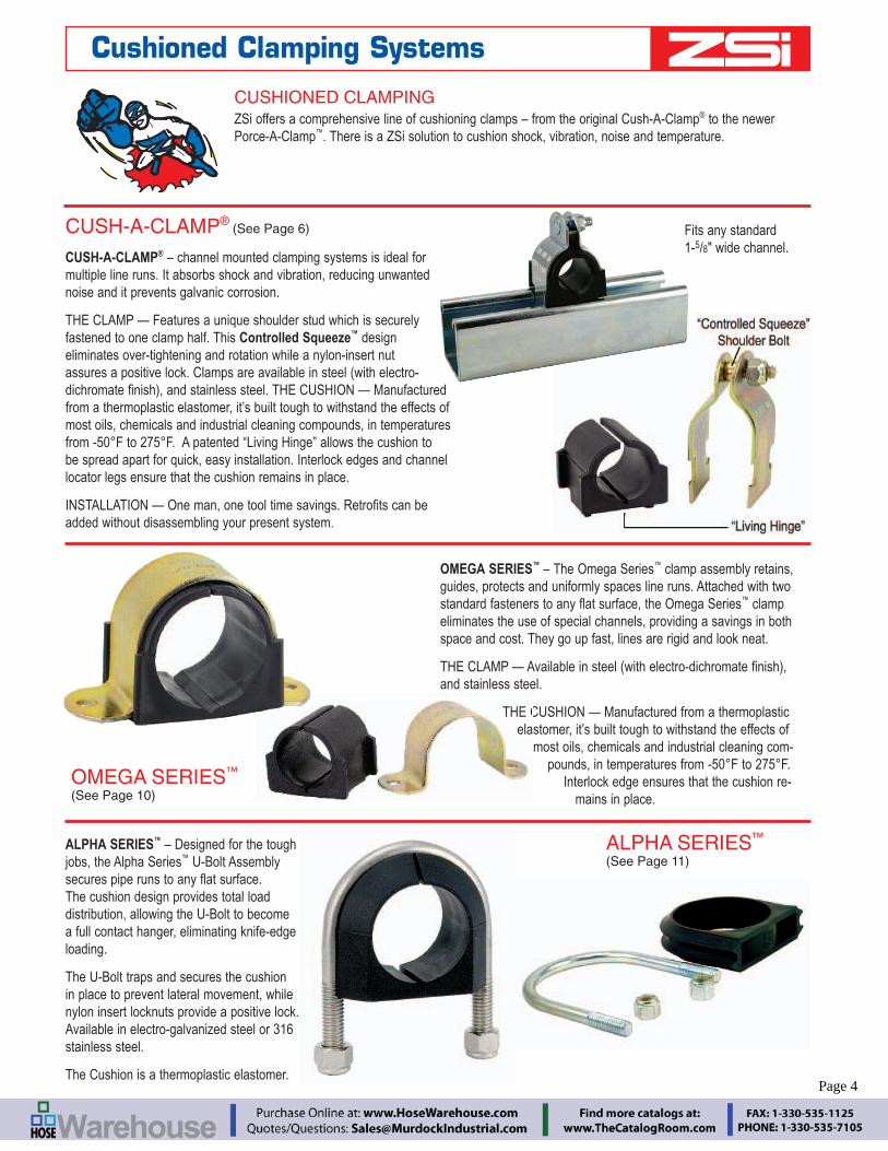
OMEGA SERIES™ – The Omega Series™ clamp assembly retains, guides, protects and uniformly spaces line runs. Attached with two
™ clamp eliminates the use of special channels, providing a savings in both space and cost. They go up fast, lines are rigid and look neat.
and stainless steel.
THE CUSHION — Manufactured from a thermoplastic elastomer, it’s built tough to withstand the effects of
most oils, chemicals and industrial cleaning com-pounds, in temperatures from -50°F to 275°F.
Interlock edge ensures that the cushion re-mains in place.
CUSH-A-CLAMP® – channel mounted clamping systems is ideal for multiple line runs. It absorbs shock and vibration, reducing unwanted noise and it prevents galvanic corrosion.
THE CLAMP — Features a unique shoulder stud which is securely fastened to one clamp half. This Controlled Squeeze™ design eliminates over-tightening and rotation while a nylon-insert nut assures a positive lock. Clamps are available in steel (with electro-
from a thermoplastic elastomer, it’s built tough to withstand the effects of most oils, chemicals and industrial cleaning compounds, in temperatures from -50°F to 275°F. A patented “Living Hinge” allows the cushion to be spread apart for quick, easy installation. Interlock edges and channel locator legs ensure that the cushion remains in place.
added without disassembling your present system.
ALPHA SERIES™ – Designed for the tough jobs, the Alpha Series™ U-Bolt Assembly
The cushion design provides total load distribution, allowing the U-Bolt to become a full contact hanger, eliminating knife-edge loading.
The U-Bolt traps and secures the cushion in place to prevent lateral movement, while nylon insert locknuts provide a positive lock. Available in electro-galvanized steel or 316 stainless steel.
The Cushion is a thermoplastic elastomer.
THE Cela
Fits any standard 1-5/8" wide channel.
CUSHIONED CLAMPINGZSi offers a comprehensive line of cushioning clamps – from the original Cush-A-Clamp® to the newer Porce-A-Clamp™. There is a ZSi solution to cushion shock, vibration, noise and temperature.
CUSH-A-CLAMP® (See Page 6)
OMEGA SERIES™
(See Page 10)
ALPHA SERIES™
(See Page 11)
Cushioned Clamping Systems
Page 4

BREC
O Qu
ick
Disc
onne
ctGa
mm
a Pa
dsZ-
Clam
psBe
ta C
lam
psZ-
Stru
t Cha
nnel
sCu
sh-A
-Blo
ckLo
op &
Hos
e Cl
amps
Insu
latin
g Cl
ampi
ngCu
shio
ned
Clam
ping
Engineering Catalog www.zsi-inc.com – 5 –
CUSH-A-STRIP™ is manufactured from a thermoplastic elastomer, Cush-A-Strip™ is designed for use from -50°F to 275°F. Cush-A-Strip™ is Packaged in 20 foot rolls in an E-Z dispenser box for conve-nience in handling and storage.
Cush-A-Strip™ is designed for use with standard steel clamps ranging from 1⁄4" tube to 6" pipe.
The special locking lip edges ensure that Cush-A-Strip™ will remain in place with a balanced grip.
Porce-A-Clamp™ Replaces Porcelain and Maple Cable Clamp. Assembly consists of thermoplastic elastomer cushion with plated or stainless steel clamp. Plated steel and stainless are both supplied with
the cable at the clamping location.
Porce-A-Clamp™ offers a convenient alternative to troublesome porcelain since it is made from non-breakable material.
Flame RetardantHalogen FreeFlame RetardantHalogen Free
Flame RetardantFlame Retardant
FLAME RETARDANT PRODUCTS
They are available in two different types of cushion. The Flame Retardant/High Hardness cushion is designed for applications such as wire and cable insulation, electrical connectors, seals, gaskets and boots. The Halogen-Free/Flame Retardant cushions contain an opti-mal combination of rubbers and thermoplastics reactively combined
Flame retardant options are indicated by the logos shown below.
CUSH-A-STRIP™
(See Page 9)
PORCE-A-CLAMP™
(See Page 12)
Cushioned Clamping Systems
CUSH-A-GRIP
(See Page 8)
CUSH-A-CLAW
(See Page 7)CUS CSee Page 7)
CUSH-A-CLIP
(See Page 8)
Cush-A-Grip non-metallic strut clamps allow quick and easy attach-ment of pipe, tube, and hose to Z-Strut support channels and are corrosion resistant. They offer a cost effective alternative to metallic clamps.
Cush-A-Claw Grabs on to your Tube, Pipe, or Hose and holds it in place. The unique one piece patent pending design allows for quick, simple, and easy installation. It will not rust because it's molded from the same choice TPE Material of some of our other products that you've come to know and trust.
Avalable for surface mount, or strut mount.
Cush-A-Clip is a simple, economical lightweight hanger for support-ing tubing. The secure but non-tightening design allows for expan-sion, greatly reducing joint fractures
Page 5
– 6 – www.zsi-inc.com
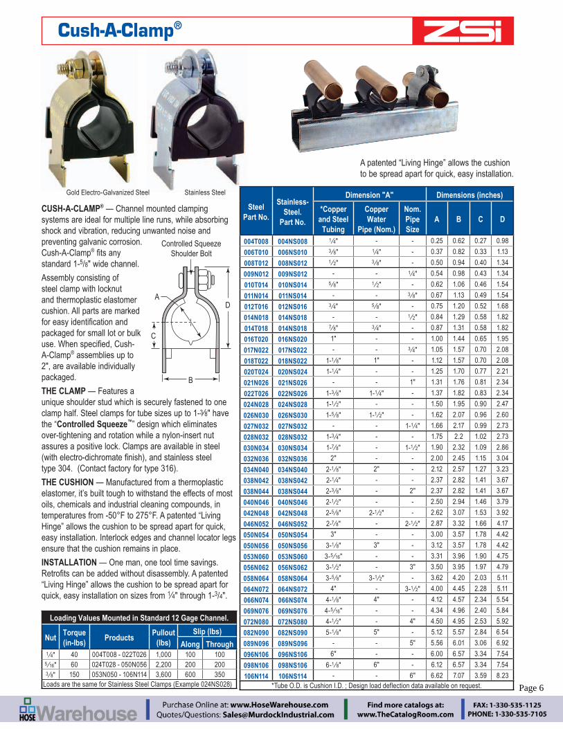
CUSH-A-CLAMP® — Channel mounted clamping systems are ideal for multiple line runs, while absorbing shock and vibration, reducing unwanted noise and preventing galvanic corrosion. Cush-A-Clamp®
standard 1-5/8" wide channel.
Assembly consisting of steel clamp with locknut and thermoplastic elastomer cushion. All parts are marked
packaged for small lot or bulk
A-Clamp® assemblies up to 2", are available individually packaged.
THE CLAMP — Features a unique shoulder stud which is securely fastened to one clamp half. Steel clamps for tube sizes up to 1-3⁄8" have the “Controlled Squeeze™” design which eliminates over-tightening and rotation while a nylon-insert nut assures a positive lock. Clamps are available in steel
THE CUSHION — Manufactured from a thermoplastic elastomer, it’s built tough to withstand the effects of most oils, chemicals and industrial cleaning compounds, in temperatures from -50°F to 275°F. A patented “Living Hinge” allows the cushion to be spread apart for quick, easy installation. Interlock edges and channel locator legs ensure that the cushion remains in place.
INSTALLATION — One man, one tool time savings.
“Living Hinge” allows the cushion to be spread apart for quick, easy installation on sizes from 1⁄4" through 1-3/4".
C
B
D
Controlled SqueezeShoulder Bolt
A
Gold Electro-Galvanized Steel Stainless Steel
A patented “Living Hinge” allows the cushion to be spread apart for quick, easy installation.
Cush-A-Clamp®
Steel Part No.
Stainless-Steel.
Part No.
Dimension "A" Dimensions (inches)
*Copper and Steel
Tubing
Copper Water
Pipe (Nom.)
Nom. Pipe Size
A B C D
004T008 004NS008 1 ⁄4" - - 0.25 0.62 0.27 0.98
006T010 006NS010 3 ⁄8" 1 ⁄4" - 0.37 0.82 0.33 1.13
008T012 008NS012 1 ⁄2" 3 ⁄8" - 0.50 0.94 0.40 1.34
009N012 009NS012 - - 1 ⁄4" 0.54 0.98 0.43 1.34
010T014 010NS014 5 ⁄8" 1 ⁄2" - 0.62 1.06 0.46 1.54
011N014 011NS014 - - 3 ⁄8" 0.67 1.13 0.49 1.54
012T016 012NS016 3 ⁄4" 5 ⁄8" - 0.75 1.20 0.52 1.68
014N018 014NS018 - - 1 ⁄2" 0.84 1.29 0.58 1.82
014T018 014NS018 7 ⁄8" 3 ⁄4" - 0.87 1.31 0.58 1.82
016T020 016NS020 1" - - 1.00 1.44 0.65 1.95
017N022 017NS022 - - 3 ⁄4" 1.05 1.57 0.70 2.08
018T022 018NS022 1-1 ⁄8" 1" - 1.12 1.57 0.70 2.08
020T024 020NS024 1-1 ⁄4" - - 1.25 1.70 0.77 2.21
021N026 021NS026 - - 1" 1.31 1.76 0.81 2.34
022T026 022NS026 1-3 ⁄8" 1-1 ⁄4" - 1.37 1.82 0.83 2.34
024N028 024NS028 1-1 ⁄2" - - 1.50 1.95 0.90 2.47
026N030 026NS030 1-5 ⁄8" 1-1 ⁄2" - 1.62 2.07 0.96 2.60
027N032 027NS032 - - 1-1 ⁄4" 1.66 2.17 0.99 2.73
028N032 028NS032 1-3 ⁄4" - - 1.75 2.2 1.02 2.73
030N034 030NS034 1-7 ⁄8" - 1-1 ⁄2" 1.90 2.32 1.09 2.86
032N036 032NS036 2" - - 2.00 2.45 1.15 3.04
034N040 034NS040 2-1 ⁄8" 2" - 2.12 2.57 1.27 3.23
038N042 038NS042 2-1 ⁄4" - - 2.37 2.82 1.41 3.67
038N044 038NS044 2-3 ⁄8" - 2" 2.37 2.82 1.41 3.67
040N046 040NS046 2-1 ⁄2" - - 2.50 2.94 1.46 3.79
042N048 042NS048 2-5 ⁄8" 2-1 ⁄2" - 2.62 3.07 1.53 3.92
046N052 046NS052 2-7 ⁄8" - 2-1 ⁄2" 2.87 3.32 1.66 4.17
050N054 050NS054 3" - - 3.00 3.57 1.78 4.42
050N056 050NS056 3-1 ⁄8" 3" - 3.12 3.57 1.78 4.42
053N060 053NS060 3-5 ⁄16" - - 3.31 3.96 1.90 4.75
056N062 056NS062 3-1 ⁄2" - 3" 3.50 3.95 1.97 4.79
058N064 058NS064 3-5 ⁄8" 3-1 ⁄2" - 3.62 4.20 2.03 5.11
064N072 064NS072 4" - 3-1 ⁄2" 4.00 4.45 2.28 5.11
066N074 066NS074 4-1 ⁄8" 4" - 4.12 4.57 2.34 5.54
069N076 069NS076 4-5 ⁄16" - - 4.34 4.96 2.40 5.84
072N080 072NS080 4-1 ⁄2" - 4" 4.50 4.95 2.53 5.92
082N090 082NS090 5-1 ⁄8" 5" - 5.12 5.57 2.84 6.54
089N096 089NS096 - - 5" 5.56 6.01 3.06 6.92
096N106 096NS106 6" - - 6.00 6.57 3.34 7.54
098N106 098NS106 6-1 ⁄8" 6" - 6.12 6.57 3.34 7.54
106N114 106NS114 - - 6" 6.62 7.07 3.59 8.23*Tube O.D. is Cushion I.D. ; Design load deflection data available on request.
Loading Values Mounted in Standard 12 Gage Channel.
NutTorque (in-lbs)
ProductsPullout
(lbs)Slip (lbs)
Along Through1 ⁄4" 40 004T008 - 022T026 1,000 100 100
5 ⁄16" 60 024T028 - 050N056 2,200 200 2003 ⁄8" 150 053N050 - 106N114 3,600 600 350
Page 6

BREC
O Qu
ick
Disc
onne
ctGa
mm
a Pa
dsZ-
Clam
psBe
ta C
lam
psZ-
Stru
t Cha
nnel
sCu
sh-A
-Blo
ckLo
op &
Hos
e Cl
amps
Insu
latin
g Cl
ampi
ngCu
shio
ned
Clam
ping
Engineering Catalog www.zsi-inc.com – 7 –
Cush-A-Claw
SizeRange
The Cush-A-Claw Grabs on to your Tube, Pipe, or Hose and holds it in place. The unique one piece patent pending design allows for quick, simple, and easy installation. It will not rust because it's mold-ed from the same choice TPE Material of some of our other products that you've come to know and trust.
Easy Snap-in Installation of Tube, Pipe, or Hose
Sure Grip Strut Base easily rotates into strut
Will not Rust
Non Conducting
Saves Time and Money
Temp Range: -50° to 275° F
Works Great Indoors or Outdoors
Six Sizes of Tube and Three Sizes of EMT
Designed for Light Duty Loads and Applications
Prevents Galvanic Corrosion of Dissimilar Metals
An Excellent Alternative to Steel, Stainless Steel, or Galvanized Clamps.
Cush-A-Claw® is manufactured under U.S. patent D631739
Surface Mounted
Strut Mounted
75 Lbs. Load(safety Factor 3)
O.D. Tube Size EMTS Conduit SizesStrut
Mount Part #
Surface Mount Part #.
Size Strut Mount Part #
Surface Mount Part #.
Size
O.D. In. O.D. In.
CL-04 CLS-04 14" 0.250 EMT-1/2 EMTS-1/2 1
2" 0.706
CL-06 CLS-06 38" 0.375 EMT-3/4 EMTS-3/4 3
4" 0.922
CL-08 CLS-08 12" 0.500 EMT-1 EMTS-1 1" 1.163
CL-10 CLS-10 58" 0.625
CL-12 CLS-12 34" 0.750
CL-14 CLS-14 78" 0.875
CL-18 CLS-18 118" 1.125
Insert Twist & Lock Position Pipe Snap In
Position Mount w/Screw Position Pipe Snap In
Side grooves provide Centering guide
Counter-sunk hole allows tightening of any type of #10 fastener
Page 7

– 8 – www.zsi-inc.com
A SIMPLE, ECONOMICAL, LIGHTWEIGHT HANGER FOR SUPPORTING TUBING
Manufactured from polyamide alloy
U.L. Rated
Sizes from 3/8" to 1-1⁄8"
One piece design makes installation a snap.
No nuts to tighten, no parts to lose.
Temperatures from -40°F to 275°F
Secure but non-tightening design allows for expansion, greatly reducing joint fractures
Size
CUSH-A-CLIP
CUSH-A-GRIP Multi-size adjustment capability allows four clamp
complete with stainless steel bolt and captured nut hardware.
FEATURES
ADVANTAGES Reduces inventory SKU’s
projects using both tube and pipe sizes Easy installation, Non conducting Permissible outdoors
No galvanic reaction, Will not rust
BENEFITS Lowers overall inventory costs Works with screw or nut driver Resists vibration Use in place of steel clamps with steel tube Multi-environmental Covers a wide range of applications and
maintains thermal barrier For use on copper tube Use in place of stainless, aluminum,
PVC or hot dipped galvanized clamps
SizeRange
Hex Bolt
"V" Pad
B
C
D
V-Pad
17⁄16"
A
Patented Product
Cush-A-Clip, Cush-A-Grip
Part Number
Tube Sizes Only
Wt.⁄ 100
3 ⁄8" 2.51 ⁄2" 2.55 ⁄8" 3.03 ⁄4" 3.07 ⁄8" 4.5
1-1 ⁄8" 4.5
Part No.
O.D. Tube Sizes
Pipe Sizes
Metric Sizes
Diameters (in)
CG-10 1 ⁄4" 3 ⁄8" 1 ⁄2" 1 ⁄4" 6mm – 14mm 0.25 – 0.54
CG-20 5 ⁄8" 3 ⁄4" 7 ⁄8" 3 ⁄8" – 1 ⁄2" 15mm – 22mm 0.62 – 0.87
CG-30 7 ⁄8" 1" 1-1 ⁄8" 3 ⁄4" 22mm – 28mm 0.87 – 1.12
CG-40 1" 1-1 ⁄8" 1-1 ⁄4" 3 ⁄4" – 1" 26mm – 32mm 1.00 – 1.31
Part No.
Nominal Pipe Size
Dimensions Hex Head Cap Screw & Lock Nut"A" "B" "C" "D"
CG-10 1 ⁄4" 1-15 ⁄16" 1-3 ⁄8" 3 ⁄8" 3 ⁄16" 1 ⁄4"-20 x 1-1 ⁄2"
CG-20 3 ⁄8" 2-3 ⁄8" 1-5 ⁄8" 7 ⁄16" 1 ⁄4" 1 ⁄4"-20 x 2"
CG-30 1 ⁄2" 2-9 ⁄16" 1-13 ⁄16" 7 ⁄16" 5 ⁄16" 1 ⁄4"-20 x 2"
CG-40 3 ⁄4" 2-11 ⁄16" 1-15 ⁄16" 7 ⁄16" 5 ⁄16" 1 ⁄4"-20 x 2"
Page 8

BREC
O Qu
ick
Disc
onne
ctGa
mm
a Pa
dsZ-
Clam
psBe
ta C
lam
psZ-
Stru
t Cha
nnel
sCu
sh-A
-Blo
ckLo
op &
Hos
e Cl
amps
Insu
latin
g Cl
ampi
ngCu
shio
ned
Clam
ping
Engineering Catalog www.zsi-inc.com – 9 –
Lock-lip EdgeCompression Ribs
1.62"
Varies up to 0.23"
Manufactured from a thermoplastic elastomer, Cush-A-Strip™ is designed for use from -50°F to 275°F.
Easy Stocking – Packaged in 20 foot rolls in an E-Z dispenser box for convenience in handling and storage. Cush-A-Strip™ roll part number is S-716
Easy Measuring – Marked in 1⁄4" increments for fast measuring and cutting, while eliminating waste.
Lock-lip edges ensure that Cush-A-Strip™ will remain in place with a balanced grip.
Clamps ordered separately. They are available with a standard
steel, in sizes ranging from 1⁄4" tube to 6" pipe.
(1) Cut appropriate length strip using the cutting schedule shown on right.
(2) Place the pipe on the Cush-A-Strip™
(3) Insert the clamps in the strut
(4) Tighten the clamps.
Cush-A-Strip™
Cush-A-Strip™ Cutting Guide
Clamp Part No. Dimensions (Inches)
Gold Plated Steel
Stainless Steel Type
304
Clamp Size O.D.
Tube Size O.D.
Pipe Size (Nom.)
Cutting Schedule
N008C NS008 1 ⁄2" 1 ⁄4" – 7 ⁄8N101C NS101 5 ⁄8" 3 ⁄8" – 1-1 ⁄8N012C NS012 3 ⁄4" 1 ⁄2" 1 ⁄4" 1-1 ⁄2N014C NS014 7 ⁄8" 5 ⁄8" 3 ⁄8" 2
N016C NS016 1" 3 ⁄4" – 2-1 ⁄4N018C NS018 1-1 ⁄8" 7 ⁄8" 1 ⁄2" 3
N020C NS020 1-1 ⁄4" 1" 3 ⁄4" 3-1 ⁄4N022C NS022 1-3 ⁄8" 1-1 ⁄8" – 3-5 ⁄8N024C NS024 1-1 ⁄2" 1-3 ⁄16" – 3-7 ⁄8N024C NS024 1-1 ⁄2" 1-1 ⁄4" 1" 4
N026C NS026 1-5 ⁄8" 1-3 ⁄8" – 4-1 ⁄2N028C NS028 1-3 ⁄4" 1-1 ⁄2" – 4-7 ⁄8N030C CS030 1-7 ⁄8" 1-5 ⁄8" 1-1 ⁄4" 5-1 ⁄4N032C CS032 2" 1-3 ⁄4" 5-1 ⁄2N034C CS034 2-1 ⁄8" 1-7 ⁄8" 1-1 ⁄2" 6
N036C CS036 2-1 ⁄4" 2" – 6-3 ⁄8N038C CS038 2-3 ⁄8" 2-1 ⁄8" – 6-3 ⁄4N040C CS040 2-1 ⁄2" 2-1 ⁄4" – 7-1 ⁄4N042C CS042 2-5 ⁄8" 2-3 ⁄8" 2" 7-1 ⁄2N044C CS044 2-3 ⁄4" 2-1 ⁄2" – 8
N048C CS048 3" 2-3 ⁄4" – 8-3 ⁄4N050C CS050 3-1 ⁄8" 2-7 ⁄8" 2-1 ⁄2" 9-1 ⁄4N054C CS054 3-1 ⁄4" 3" – 9-1 ⁄2N060C CS060 3-3 ⁄4" 3-1 ⁄2" 3" 11
N068C CS068 4-1 ⁄4" 4" 3-1 ⁄2" 12-1 ⁄4N076C CS076 4-3 ⁄4" 4-1 ⁄2" 4" 14
N092C CS092 5-3 ⁄4" – 5" 15-1 ⁄2N110C CS110 6-7 ⁄8" – 6" 18-1 ⁄2
* Gold Plated Steel Clamps Supplied with Fixed Stud and Nylon Lock Nut* Stainless Steel Clamps Supplied with fixed Stud and Nylon Lock Nut from 1 ⁄2" through 1-3 ⁄4" Sizes and 1-7 ⁄8" through 6-7 ⁄8" Sizes are supplied with a Loose Bolt and Hex Nut
Page 9

– 10 – www.zsi-inc.com
The Omega Series™ clamp assembly retains, guides, protects and uniformly spaces line runs. Attached with two
Omega Series™ clamp eliminates the use of special channels, providing a savings in both space and cost. They go up fast, lines are rigid and look neat.
THE CLAMP — Steel with electro-
304.
THE CUSHION — Manufactured from a thermoplastic elastomer, it’s built tough to withstand the effects of most oils, chemicals and industrial cleaning compounds, in temperatures from -50°F to 275°F. Interlock edge ensures that the cushion remains in place.
Stainless Steel
C
ED
B
A
F
Assembly consists of clamp and thermoplastic elastomer cushion. Fasteners not included.
Gold Electro-Galvanized Steel
Omega Series™
Steel Part No.
Stainless Steel
Part No.
Copper & Steel Tubing
O.D.
Copper Water Pipe
(Nom.)
Pipe Size
(Nom.)
Dimensions (inches)Hanging Design LoadA B C D E F
004M007 004MS007 1 ⁄4" - - 0.25 0.48 0.60 0.22 0.26 0.78 50
006M008 006MS008 3 ⁄8" 1 ⁄4" - 0.37 0.62 0.66 0.31 0.26 0.81 50
008M011 008MS011 1 ⁄2" 3 ⁄8" 1 ⁄4" 0.50 0.81 0.83 0.40 0.26 0.98 50
010M013 010MS013 5 ⁄8" 1 ⁄2" 3 ⁄8" 0.62 0.93 0.85 0.46 0.26 0.98 50
012M015 012MS015 3 ⁄4" 5 ⁄8" - 0.75 1.02 0.90 0.50 0.26 0.98 50
014M017 014MS017 7 ⁄8" 3 ⁄4" 1 ⁄2" 0.87 1.12 1.03 0.53 0.26 0.98 50
016M019 016MS019 1" - - 1.00 1.24 1.04 0.59 0.26 0.98 50
018M020 018MS020 - - 3 ⁄4" 1.05 1.40 1.11 0.70 0.26 0.98 50
018M021 018MS021 1-1 ⁄8" 1" - 1.12 1.40 1.17 0.70 0.26 0.98 50
020M024 020MS024 1-1 ⁄4" - - 1.25 1.60 1.20 0.77 0.26 1.56 50
021M026 021MS026 - - 1" 1.31 1.71 1.28 0.81 0.26 1.56 50
022M026 022MS026 1-3 ⁄8" 1-1 ⁄4" - 1.37 1.71 1.28 0.83 0.26 1.56 50
024M028 024MS028 1-1 ⁄2" - - 1.50 1.85 1.36 0.90 0.26 1.56 200
026M030 026MS030 1-5 ⁄8" 1-1 ⁄2" - 1.62 1.98 1.43 0.96 0.26 1.56 200
027M032 027MS032 - - 1-1 ⁄4" 1.66 2.12 1.55 0.99 0.34 1.56 400
028M032 028MS032 1-3 ⁄4" - - 1.75 2.12 1.55 1.02 0.34 1.56 400
030M034 030MS034 1-7 ⁄8" - 1-1 ⁄2" 1.87 2.25 1.64 1.09 0.34 1.56 400
032M036 032MS036 2" - - 2.00 2.38 1.69 1.15 0.34 1.56 400
034M040 034MS040 2-1 ⁄8" - - 2.12 2.62 1.86 1.27 0.34 1.56 400
038M044 038MS044 2-3 ⁄8" - 2" 2.37 2.88 1.94 1.41 0.34 1.56 400
040M046 040MS046 2-1 ⁄2" - - 2.50 3.00 2.00 1.47 0.34 1.56 400
042M048 042MS048 2-5 ⁄8" 2-1 ⁄2" - 2.62 3.13 2.07 1.53 0.34 1.56 400
046M052 046MS052 2-7 ⁄8" - 2-1 ⁄2" 2.87 3.38 2.19 1.65 0.34 1.56 400
050M056 050MS056 3-1 ⁄8" 3" - 3.12 3.68 2.32 1.78 0.34 1.56 400
056M062 056MS062 3-1 ⁄2" - 3" 3.50 4.06 2.50 1.97 0.34 1.56 400
058M064 058MS064 3-5 ⁄8" 3-1 ⁄2" - 3.62 4.19 2.57 2.03 0.34 1.56 700
064M072 064MS072 4" - 3-1 ⁄2" 4.00 4.68 2.82 2.28 0.34 1.56 700
066M074 066MS074 4-1 ⁄8" 4" - 4.12 4.84 3.05 2.34 0.43 1.56 800
072M080 072MS080 4-1 ⁄2" - 4" 4.50 5.22 3.24 2.53 0.43 1.56 800
082M090 082MS090 5-1 ⁄8" 5" - 5.12 5.82 3.55 2.84 0.43 1.56 800
089M096 089MS096 - - 5" 5.56 6.31 4.00 3.06 0.56 1.56 1,200
098M106 098MS106 6-1 ⁄8" 6" - 6.12 6.90 4.31 3.34 0.56 1.56 1,200
106M114 106MS114 - - 6" 6.62 7.39 4.56 3.58 0.56 1.56 1,200
PART NO. SUFFIX Cushions Example
NONE Thermoplastic elastomer 004M007 (STEEL) 004MS007 (STAINLESS STEEL)
N Flame RetardantFlame Retardant 004M007N (STEEL) 004MS007N (STAINLESS STEEL)
NH Flame RetardantHalogen FreeFlame RetardantHalogen Free
004M007NH (STEEL) 004MS007NH (STAINLESS STEEL)
Note: Fasteners not included.
Page 10

BREC
O Qu
ick
Disc
onne
ctGa
mm
a Pa
dsZ-
Clam
psBe
ta C
lam
psZ-
Stru
t Cha
nnel
sCu
sh-A
-Blo
ckLo
op &
Hos
e Cl
amps
Insu
latin
g Cl
ampi
ngCu
shio
ned
Clam
ping
Engineering Catalog www.zsi-inc.com – 11 –
Designed for the tough jobs, the Alpha Series™ U-Bolt Assembly secures pipe
surface. The cushion design provides total load distribution, allowing the U-Bolt to become a full contact hanger, eliminating knife-edge loading. The U-Bolt traps and secures the cushion in place to prevent lateral movement, while nylon insert locknuts provide a positive lock.
Alpha Series™ U-Bolt Assembly con-forms to MIL-S-901D for shock testing.
FHC
D
E
AB
B
1/2" thru 6" assembly.
C H F
A
DE
8" thru 12" assembly – Two piece cushion design
30°.017π
30°.017π
GG
Alpha Series™
Assy.Part No.
Pipe Size
(Nom.)
Tube Size
(O.D.)
Dimensions (Inches)Torque
Design Load
Slip ThroughA
Dia.B
RadiusC D E F G H
1 ⁄2" – 0.840 0.80 1.60 1.50 0.67 0.68 1 ⁄4 1 ⁄4-20 UNC-2B 100 485 500
– 7 ⁄8" 0.875 0.80 1.60 1.50 0.67 0.68 1 ⁄4 1 ⁄4-20 UNC-2B 100 485 5003 ⁄4" – 1.05 0.90 1.80 1.60 0.78 0.68 1 ⁄4 1 ⁄4-20 UNC-2B 100 485 500
UB1TA – 1" 1.00 0.90 1.80 1.60 0.78 0.68 1 ⁄4 1 ⁄4-20 UNC-2B 100 485 500
– 1-1 ⁄4" 1.25 1.02 2.05 1.70 0.91 0.68 1 ⁄4 1 ⁄4-20 UNC-2B 100 485 500
UB1PA 1" – 1.31 1.02 2.05 1.70 0.91 0.68 1 ⁄4 1 ⁄4-20 UNC-2B 100 485 500
– 1-3 ⁄8" 1.375 1.02 2.05 1.70 0.91 0.68 1 ⁄4 1 ⁄4-20 UNC-2B 100 485 500
1-1 ⁄4" – 1.66 1.27 2.55 2.10 1.08 1.24 3 ⁄8 3 ⁄8-16 UNC-2B 150 1,220 500
1-1 ⁄2" – 1.90 1.40 2.80 2.20 1.19 1.24 3 ⁄8 3 ⁄8-16 UNC-2B 150 1,220 500
UB2PA 2" – 2.37 1.67 3.35 2.50 1.45 1.24 3 ⁄8 3 ⁄8-16 UNC-2B 150 1,220 500
2-1 ⁄2" – 2.87 1.95 3.90 3.00 1.69 1.24 1 ⁄2 1 ⁄2-13 UNC-2B 200 2,260 500
UB3PA 3" – 3.50 2.27 4.55 3.30 2.00 1.24 1 ⁄2 1 ⁄2-13 UNC-2B 200 2,260 500
3-1 ⁄2" – 4.00 2.52 5.05 3.70 2.25 1.24 1 ⁄2 1 ⁄2-13 UNC-2B 200 2,260 500
UB4PA 4" – 4.50 2.50 5.50 3.90 2.50 1.24 1 ⁄2 1 ⁄2-13 UNC-2B 200 2,260 500
UB5PA 5" – 5.56 3.25 6.56 4.50 3.03 1.24 1 ⁄2 1 ⁄2-13 UNC-2B 200 2,260 500
UB6PA 6" – 6.62 3.87 7.75 5.40 3.56 1.44 5 ⁄8 5 ⁄8-11 UNC-2B 250 3,620 500
UB8PA 8" – 8.62 4.85 9.82 6.40 4.56 1.44 5 ⁄8 5 ⁄8-11 UNC-2B 250 3,620 500
UB10PA 10" – 10.75 6.08 12.16 7.70 5.68 1.65 3 ⁄4 3 ⁄4-10 UNC-2B 275 5,420 500
UB12PA 12" – 12.75 7.13 14.25 8.70 6.68 1.65 3 ⁄4 3 ⁄4-10 UNC-2B 275 5,420 500
SUFFIX
Clamp Cushion Example
NONE Electro-galvanized Thermoplastic elastomer
6Stainless Steel,
Type 316 Thermoplastic elastomer
N6Stainless Steel,
Type 316 Flame RetardantFlame RetardantN Electro-galvanized
NH Electro-galvanizedFlame RetardantHalogen FreeFlame RetardantHalogen FreeNH6
Stainless Steel,Type 316
Page 11

– 12 – www.zsi-inc.com
Replaces Porcelain and Maple Cable Clamp. Assembly consists of thermoplastic elastomer cushion with plated or stainless steel clamp. Plated steel and stainless are both supplied with Silicon Bronze bolt and nut.
Non-breakable material
Chemical and UV resistant
U.L. Listed - Burning stops within 10 seconds after two
Plated Steel, or Stainless steel clamps
Dielectric strength 640 volts per mil
One piece cushion design, available with Flame retardant / Halogen Free cushions
around the Cable at the Clamping Location.
.25"
R Size
R
H
A
.85"
2.12"
The hinged cushion allows easy installation of the wire, but the components will not get separated and lost or broken.
Porce-A-Clamp™
Part No.Dimensions (Inches)
Total Assy. Height - HSize/
Hole Dia.A R
006CC018 3 ⁄8 1.12 0.56 1.82008CC018 1 ⁄2 1.12 0.56 1.82010CC018 5 ⁄8 1.12 0.56 1.82012CC026 3 ⁄4 1.62 0.81 2.34014CC026 7 ⁄8 1.62 0.81 2.34016CC026 1 1.62 0.81 2.34018CC026 1-1 ⁄8 1.62 0.81 2.34020CC034 1-1 ⁄4 2.12 1.06 2.86022CC034 1-3 ⁄8 2.12 1.06 2.86024CC034 1-1 ⁄2 2.12 1.06 2.86026CC034 1-5 ⁄8 2.12 1.06 2.86028CC042 1-3 ⁄4 2.62 1.31 3.50030CC042 1-7 ⁄8 2.62 1.31 3.50032CC042 2 2.62 1.31 3.50034CC042 2-1 ⁄8 2.62 1.31 3.50036CC050 2-1 ⁄4 3.12 1.56 4.05038CC050 2-3 ⁄8 3.12 1.56 4.05040CC050 2-1 ⁄2 3.12 1.56 4.05042CC050 2-5 ⁄8 3.12 1.56 4.05044CC058 2-3 ⁄4 3.62 1.81 4.75046CC058 2-7 ⁄8 3.62 1.81 4.75048CC058 3 3.62 1.81 4.75050CC058 3-1 ⁄8 3.62 1.81 4.75052CC066 3-1 ⁄4 4.12 2.06 5.125054CC066 3-3 ⁄8 4.12 2.06 5.125056CC066 3-1 ⁄2 4.12 2.06 5.125058CC066 3-5 ⁄8 4.12 2.06 5.125060CC074 3-3 ⁄4 4.62 2.31 5.54062CC074 3-7 ⁄8 4.62 2.31 5.54064CC074 4 4.62 2.31 5.54066CC074 4-1 ⁄8 4.62 2.31 5.54068CC080 4-1 ⁄4 5.00 2.50 5.92070CC080 4-3 ⁄8 5.00 2.50 5.92072CC080 4-1 ⁄2 5.00 2.50 5.92
SUFFIX
Note: All clamps have Silicon Bronze Hardware
Clamp Cushion Example
Z Plated SteelFlame RetardantFlame Retardant
006CC018Z
S Stainless Steel 006CC018S
ZH Plated Steel Flame RetardantHalogen FreeFlame RetardantHalogen Free
006CC018ZH
SH Stainless Steel 006CC018SH
Page 12

BREC
O Qu
ick
Disc
onne
ctGa
mm
a Pa
dsZ-
Clam
psBe
ta C
lam
psZ-
Stru
t Cha
nnel
sCu
sh-A
-Blo
ckLo
op &
Hos
e Cl
amps
Insu
latin
g Cl
ampi
ngCu
shio
ned
Clam
ping
Engineering Catalog www.zsi-inc.com – 13 –
The Saddle-Up Pipe Insulation Saddle is a formed metal shield designed to allow insulated refrigeration pipe or tubing to pass through the support without need to compromise the vapor barrier and protects from crushing or damage at hanger and support locations. Made from 20 gage electro-galvanized steel the ribbed design along its 12 inch length offers the superior support needed to spread out loading on insulation which reduces the potential for internal cavity creation between the pipe and insulation. The Z-Strut mounting option provides a time tested secure and safe attachment method so there is no need for other tie downs to the support.
OTHER FEATURES INCLUDE:
Shipped with all necessary hardware to attach to Z-Strut or any other industry standard 15⁄8" wide strut channel.
Each Saddle individually marked with part number
Counter Sunk attachment Hole and Flat Head Machine Screw prevent possible damage to insulation.
Electro-Galvanized Steel provides excellent rust protection and has no exposed fabricated edges.
ASSEMBLY SIDE VIEW
CHANNELNUT
1/4” X 3/4” FLAT HEADMACHINE SCREW
ASSEMBLY END VIEW
Z-STRUT™ CHANNEL
B
A
12”
INSULATION SADDLE
Saddle-Up
Dimensions (Inches)1⁄2"
Insulation
3⁄4" Insulation
1" Insulation
11⁄2" Insulation
Part Number
B Saddle Width
A Radius
OD Tube Size
OD With Insulation
OD Tube Size
OD With Insulation
OD Tube Size
OD With Insulation
OD Tube Size
OD With Insulation
SD150 11 ⁄2 3 ⁄43 ⁄8 13 ⁄8 – – – – – –1 ⁄2 11 ⁄2 – – – – – –
SD200 2 1
5 ⁄8 15 ⁄8 3 ⁄8 17 ⁄8 – – – –3 ⁄4 13 ⁄4 1 ⁄2 2 – – – –7 ⁄8 17 ⁄8 – – – – – –
SD250 21 ⁄2 11 ⁄411 ⁄8 21 ⁄8 5 ⁄8 21 ⁄8 3 ⁄8 23 ⁄8 – –13 ⁄8 23 ⁄8 3 ⁄4 21 ⁄4 1 ⁄2 21 ⁄2 – –– – 7 ⁄8 23 ⁄8 – – – –
SD300 3 11 ⁄215 ⁄8 25 ⁄8 11 ⁄8 25 ⁄8 5 ⁄8 25 ⁄8 – –– – 13 ⁄8 27 ⁄8 3 ⁄4 23 ⁄4 – –– – – – 7 ⁄8 27 ⁄8 – –
SD350 31 ⁄2 13 ⁄421 ⁄8 31 ⁄8 15 ⁄8 31 ⁄8 11 ⁄8 31 ⁄8 3 ⁄8 33 ⁄823 ⁄8 33 ⁄8 – – 13 ⁄8 33 ⁄8 1 ⁄2 31 ⁄2
SD450 41 ⁄2 21 ⁄4
25 ⁄8 35 ⁄8 21 ⁄8 35 ⁄8 15 ⁄8 35 ⁄8 5 ⁄8 35 ⁄8– – 23 ⁄8 37 ⁄8 – – 3 ⁄4 33 ⁄4– – – – – – 7 ⁄8 37 ⁄8
31 ⁄8 41 ⁄8 25 ⁄8 41 ⁄8 21 ⁄8 41 ⁄8 11 ⁄8 41 ⁄8– – – – 23 ⁄8 43 ⁄8 13 ⁄8 43 ⁄8
SD550 51 ⁄2 23 ⁄435 ⁄8 45 ⁄8 31 ⁄8 45 ⁄8 25 ⁄8 45 ⁄8 15 ⁄8 45 ⁄841 ⁄8 51 ⁄8 35 ⁄8 51 ⁄8 31 ⁄8 51 ⁄8 21 ⁄8 51 ⁄8– – – – – – 23 ⁄8 53 ⁄8
SD650 61 ⁄2 31 ⁄4– – 41 ⁄8 55 ⁄8 35 ⁄8 55 ⁄8 25 ⁄8 55 ⁄8– – – – 41 ⁄8 61 ⁄8 31 ⁄8 61 ⁄8
Page 13

– 14 – www.zsi-inc.com
Length
Hole Size
CushionO.D.
WallThickness
Cush-A-Therm™ Clamp is a perfect crush-resistant airtight seal for chilled refrigeration or mechanical pipe lines that require continuous insulation.
The rigid foam construction has an insulating tape inner lining which supports tube and absorbs vibration of operating pipe lines.
The outer cover consists of a special rubber coating which seals the cushion after installation in order to prevent condensation.
It's strong closed-cell structure is ideal for liquid cooling lines to prevent condensation, save energy, and maintain the vapor barrier.
AIRTIGHT CRUSH-RESISTANT INSULATION CLAMP
Cush-A-Therm™
NOTE: Complete assembly supplied with gold electro-galvanized channel clamp and hardware
FEATURES
Flammability is Self-Extinguishing as tested under ASTM D 635
Maintains thermal barrier protection
Prevents condensation
Properly supports pipe and tube
Absorbs vibration
Polyurethane foam laminated with a rubber lining
Dimensions (Inches)Nominal 1⁄2"
Wall ThicknessNominal 3⁄4"
Wall ThicknessNominal 1"
Wall ThicknessNominal 1-1/2"
Wall ThicknessNominal 2"
Wall Thickness
Hole Size
Copper I.D.
PipeO.D.
IPS LengthPartNo.
CushionO.D.
PartNo.
CushionO.D.
PartNo.
CushionO.D.
PartNo.
CushionO.D.
PartNo.
CushionO.D.
3 ⁄8 ID 1 ⁄4 3 ⁄8 - 2.953" UX3812 1.33 UX3834 1.81 UX3810 2.31 UX3815 3.31 –
1 ⁄2 ID 3 ⁄8 1 ⁄2 1 ⁄4 2.953" UX1212 1.44 UX1234 1.89 UX1210 2.39 UX1215 3.39 –
5 ⁄8 ID 1 ⁄2 5 ⁄8 3 ⁄8 2.953" UX5812 1.56 UX5834 2.05 UX5810 2.54 UX5815 3.54 UX5820 4.54
3 ⁄4 ID 5 ⁄8 3 ⁄4 - 2.953" UX3412 1.69 UX3434 2.22 UX3410 2.71 UX3415 3.71 UX3420 4.71
7 ⁄8 ID 3 ⁄4 7 ⁄8 1 ⁄2 2.953" UX7812 1.81 UX7834 2.44 UX7810 2.82 UX7815 3.82 UX7820 4.82
1-1 ⁄8 ID 1 1-1 ⁄8 3 ⁄4 2.953" UX11812 2.19 UX11834 2.76 UX11810 3.06 UX11815 4.06 UX11820 5.06
1-3 ⁄8 ID 1-1 ⁄4 1-3 ⁄8 1 2.953" UX13812 2.31 UX13834 3.19 UX13810 3.33 UX13815 4.33 UX13820 5.33
1-5 ⁄8 ID 1-1 ⁄2 1-5 ⁄8 1-1 ⁄4 2.953" UX15812 2.56 UX15834 3.35 UX15810 3.65 UX15815 4.65 UX15820 5.65
1-7 ⁄8 ID – 1-7 ⁄8 2.953" UX17812 2.81 UX17834 3.58 UX17810 4.43 UX17815 5.43 UX17820 6.43
2-1 ⁄8 ID 2 2-1 ⁄8 - 2.953" UX21812 3.23 UX21834 3.86 UX21810 4.16 UX21815 5.16 UX21820 6.16
2-3 ⁄8 ID 2-1 ⁄4 2-3 ⁄8 2 2.953" UX23812 3.48 UX23834 4.29 UX23810 3.92 UX23815 4.92 UX23820 5.92
2-5 ⁄8 ID 2-1 ⁄2 2-5 ⁄8 - 3.937" UX25812 4.13 UX25834 4.87 UX25810 4.87 UX25815 5.87 UX25820 6.87
2-7 ⁄8 ID – 2-7 ⁄8 2-1 ⁄2 3.937" UX27812 4.38 UX27834 4.57 UX27810 4.67 UX27815 5.67 UX27820 6.67
3-1 ⁄8 ID 3 3-1 ⁄8 - 3.937" UX31812 4.63 UX31834 5.00 UX31810 5.14 UX31815 6.14 UX31820 7.14
3-1 ⁄2 ID – 3-1 ⁄2 3 3.937" UX31212 4.88 UX31234 5.35 UX31210 5.89 UX31215 6.89 UX31220 7.89
3-5 ⁄8 ID 3-1 ⁄2 3-5 ⁄8 - 3.937" UX35812 5.13 UX35834 5.94 UX35810 6.44 UX35815 7.44 UX35820 8.44
4-1 ⁄8 ID 4 4-1 ⁄8 3-1 ⁄2 3.937" UX41812 5.63 UX41834 6.14 UX41810 6.48 UX41815 7.48 UX41820 8.48 Page 14

BREC
O Qu
ick
Disc
onne
ctGa
mm
a Pa
dsZ-
Clam
psBe
ta C
lam
psZ-
Stru
t Cha
nnel
sCu
sh-A
-Blo
ckLo
op &
Hos
e Cl
amps
Insu
latin
g Cl
ampi
ngCu
shio
ned
Clam
ping
Engineering Catalog www.zsi-inc.com – 15 –
AIRTIGHT CRUSH-RESISTANT INSULATION CLAMP
Cush-A-Therm™
INSTALLATION IS AS EASY AS 1-2-3!
Plastic Connector
v.s. Plastic Alternative
Pipe Insulation
Air Space (loss of insulation)
Insulation Glued to Cush-A-Thermwhich Avoids Air Space and Loss of Insulation
Plastic Connector is Thermal Conductor
Only Insulation Contacts Pipeno Thermal Conductor
Pipe Insulation
Cush-A-Therm
Pipe Insulation
Pipe Insulation
Cush-A-Therm
1. Insulation slides over pipes. Self adhesive surfaces provide seal.
2 Put in place and glue to insulation. 3. Wrap and seal with ProTape.
Page 15

– 16 – www.zsi-inc.com
Cal-Clamp InsulationCAL-CLAMP CRUSH RESISTANT INSULATION
MODEL “HW” - For Hot or Cold applications Works equally well on both hot and cold lines.
Includes the strut clamps required for installation with strut.
Special order insulation lengths, double sheet metal wrap, load bearing plates and alternate sheet metal gauges are available upon request.
MODEL “CWP” - For applications requiring a wet lag insulation
Insulations extends 1" beyond sheet metal.
The minimum length for our “CWP” insert is 6” .
Includes the strut clamps required for installation with strut.
Special order insulation lengths, double sheet metal wrap, load bearing plates and alternate sheet metal gauges are available upon request.
Material:
for water resistance, encased in a 360 degree A-653 Galvanized Sheet Metal jacket (304SS and 316SS
Minimum 140PSI compressive strength. Working Temperature is 42 to 1200 degrees F. Lower temps upon request.
Sheet Metal Gauge1
Insulation Thickness
I.P.S. NOMINAL
1" 1-1 ⁄2" 2" 2-1 ⁄2" 3" 4"
1 ⁄2" to 1-1 ⁄2" 24 20
2" to 5" 20
6" 20 16
8" to 24" 16
1A double thickness of sheet metal is recommended on the lower half when used with rollers or when hanger span exceeds ten feet.
Maximum Allowable Load (lbs)
Pipe Size HW/CWP1 ⁄2" 51
3 ⁄4" 62
1" 72
1-1 ⁄4" 92
1-1 ⁄2" 123
2" 164
2-1 ⁄2" 225
3" 276
4" 388
5" 500
6" 612
8" 827
10" 1102
12" 1326
Insulation Length Specification (in.)
Insulation Thickness
I.P.S.NOMINAL
1" 1-1 ⁄2" 2" 2-1 ⁄2" 3" 4"
1 ⁄2" to 1-1 ⁄2" 4"* 6"
2" 6"
2-1 ⁄2"’ to 6" 6" 9"
8" to 10" 9"
12" to 18" 12"
*CWP Model Inserts have a minimum length of 6"
**Larger Sizes Available Upon Requestt
Page 16

BREC
O Qu
ick
Disc
onne
ctGa
mm
a Pa
dsZ-
Clam
psBe
ta C
lam
psZ-
Stru
t Cha
nnel
sCu
sh-A
-Blo
ckLo
op &
Hos
e Cl
amps
Insu
latin
g Cl
ampi
ngCu
shio
ned
Clam
ping
Engineering Catalog www.zsi-inc.com – 17 –
Cal-Clamp InsulationMODEL “HW”
For Hot or Cold applications
Strut Clamp included
Model HWP, Insulation and Strut Clamps
IPSPipe OD
1 ⁄2" 1" 11 ⁄2" 2" 21 ⁄2" 3"
Part No.
Insulation O.D.
Part No.
Insulation O.D.
Part No.
Insulation O.D.
Part No.
Insulation O.D.
Part No.
Insulation O.D.
Part No.
Insulation O.D.
34" 1.05 HWP3412 2.16 HWP3410 2.82 HWP3415 3.95 HWP3420 4.95 HWP3425 - HWP3430 -
1" 1.315 HWP112 2.41 HWP110 3.45 HWP115 4.45 HWP120 5.51 HWP125 - HWP130 -
1-14" 1.66 HWP11412 2.72 HWP11410 3.45 HWP11415 4.95 HWP11420 5.51 HWP11425 - HWP11430 -
1-12" 1.99 HWP11212 2.99 HWP11210 3.95 HWP11215 4.95 HWP11220 6.57 HWP11225 7.57 HWP11230 8.57
2" 2.375 HWP212 3.42 HWP210 4.45 HWP215 5.51 HWP220 6.57 HWP225 7.57 HWP230 8.57
2-12" 2.875 HWP21212 3.93 HWP21210 4.95 HWP21215 6.57 HWP21220 7.57 HWP21225 8.57 HWP21230 9.57
3" 3.5 HWP312 4.56 HWP310 5.51 HWP315 6.57 HWP320 7.57 HWP325 8.57 HWP330 9.57
3-12" 4 HWP31212 5.07 HWP31210 6.57 HWP31215 7.57 HWP31220 8.57 HWP31225 9.57 HWP31230 10.7
4" 4.5 HWP412 5.57 HWP410 6.57 HWP415 7.57 HWP420 8.57 HWP425 9.57 HWP430 10.7
5" 5.563 HWP512 6.64 HWP510 7.57 HWP515 8.57 HWP520 9.57 HWP525 10.7 HWP530 11.7
6" 6.625 HWP612 7.71 HWP610 8.57 HWP615 9.57 HWP620 10.7 HWP625 11.7 HWP630 12.7
8" 8.625 HWP812 9.74 HWP810 10.7 HWP815 11.7 HWP820 12.7 HWP825 13.95 HWP830 14.95
10" 10.75 HWP1012 11.87 HWP1010 12.7 HWP1015 13.95 HWP1020 14.95 HWP1025 15.95 HWP1030 16.95
12" 12.75 HWP1212 13.88 HWP1210 14.95 HWP1215 15.95 HWP1220 16.95 HWP1225 17.95 HWP1230 18.95
Model HWT, Copper Tube Sizes, Insulation and Strut Clamps
Copper
Tube
Tube
OD
1 ⁄2" 1" 11 ⁄2" 2" 21 ⁄2" 3"
Part
No.
Insulation
O.D.
Part
No.
Insulation
O.D.
Part
No.
Insulation
O.D.
Part
No.
Insulation
O.D.
Part
No.
Insulation
O.D.
Part
No.
Insulation
O.D.1
2" 58" HWT5812 1.66 HWT5812 2.82 HWT5812 3.45 - - - - - -
34" 7
8" HWT7812 1.92 HWT7812 2.82 HWT7812 3.95 HWT7812 4.95 - - - -
1" 1-18" HWT11812 2.16 HWT11812 2.82 HWT11812 3.95 HWT11812 4.95 - - - -
1-14" 1-3
8" HWT13812 2.41 HWT13812 3.45 HWT13812 4.45 HWT13812 5.51 - - - -
1-12" 1-5
8" HWT15812 2.72 HWT15812 3.45 HWT15812 4.95 HWT15812 5.51 - - - -
2" 2-18" HWT21812 3.16 HWT21812 3.95 HWT21812 4.95 HWT21812 6.57 HWT21812 7.57 HWT21812 8.57
2-12" 2-5
8" HWT25812 3.66 HWT25812 4.45 HWT25812 5.51 HWT25812 6.57 HWT25812 7.57 HWT25812 8.57
3" 3-18" HWT31812 4.16 HWT31812 4.95 HWT31812 6.57 HWT31812 7.57 HWT31812 8.57 HWT31812 9.57
4" 4-18" HWT41812 5.16 HWT41812 6.57 HWT41812 7.57 HWT41812 8.57 HWT41812 9.57 HWT41812 10.7
5" 5-18" HWT51812 6.16 HWT51812 7.57 HWT51812 8.57 HWT51812 9.57 HWT51812 10.7 HWT51812 11.7
6" 6-18" HWT61812 7.16 HWT61812 8.57 HWT61812 9.57 HWT61812 10.7 HWT61812 11.7 HWT61812 12.7 Page 17

– 18 – www.zsi-inc.com
Cal-Clamp InsulationMODEL “CW”
For applications requiring a wet lag insulation. Insulations extends 1" beyond metal.
Strut Clamp included
Model CWP, Insulation and Strut Clamps
IPSPipe OD
1 ⁄2" 1" 11 ⁄2" 2" 21 ⁄2" 3"
Part No.
Insulation O.D.
Part No.
Insulation O.D.
Part No.
Insulation O.D.
Part No.
Insulation O.D.
Part No.
Insulation O.D.
Part No.
Insulation O.D.
3 ⁄4" 1.05 CWP3412 2.16 CWP3410 2.82 CWP3415 3.95 CWP3420 4.95 CWP3425 - CWP3430 -
1" 1.315 CWP112 2.41 CWP110 3.45 CWP115 4.45 CWP120 5.51 CWP125 - CWP130 -
1-1 ⁄4" 1.66 CWP11412 2.72 CWP11410 3.45 CWP11415 4.95 CWP11420 5.51 CWP11425 - CWP11430 -
1-1 ⁄2" 1.99 CWP11212 2.99 CWP11210 3.95 CWP11215 4.95 CWP11220 6.57 CWP11225 7.57 CWP11230 8.57
2" 2.375 CWP212 3.42 CWP210 4.45 CWP215 5.51 CWP220 6.57 CWP225 7.57 CWP230 8.57
2-1 ⁄2" 2.875 CWP21212 3.93 CWP21210 4.95 CWP21215 6.57 CWP21220 7.57 CWP21225 8.57 CWP21230 9.57
3" 3.5 CWP312 4.56 CWP310 5.51 CWP315 6.57 CWP320 7.57 CWP325 8.57 CWP330 9.57
3-1 ⁄2" 4 CWP31212 5.07 CWP31210 6.57 CWP31215 7.57 CWP31220 8.57 CWP31225 9.57 CWP31230 10.7
4" 4.5 CWP412 5.57 CWP410 6.57 CWP415 7.57 CWP420 8.57 CWP425 9.57 CWP430 10.7
5" 5.563 CWP512 6.64 CWP510 7.57 CWP515 8.57 CWP520 9.57 CWP525 10.7 CWP530 11.7
6" 6.625 CWP612 7.71 CWP610 8.57 CWP615 9.57 CWP620 10.7 CWP625 11.7 CWP630 12.7
8" 8.625 CWP812 9.74 CWP810 10.7 CWP815 11.7 CWP820 12.7 CWP825 13.95 CWP830 14.95
10" 10.75 CWP1012 11.87 CWP1010 12.7 CWP1015 13.95 CWP1020 14.95 CWP1025 15.95 CWP1030 16.95
12" 12.75 CWP1212 13.88 CWP1210 14.95 CWP1215 15.95 CWP1220 16.95 CWP1225 17.95 CWP1230 18.95
Model CWT, Copper Tube Sizes, Insulation and Strut Clamps
Copper
Tube
Tube
OD
1 ⁄2" 1" 11 ⁄2" 2" 21 ⁄2" 3"
Part
No.
Insulation
O.D.
Part
No.
Insulation
O.D.
Part
No.
Insulation
O.D.
Part
No.
Insulation
O.D.
Part
No.
Insulation
O.D.
Part
No.
Insulation
O.D.
1 ⁄2" 58" CWT5812 1.66 CWT5812 2.82 CWT5812 3.45 - - - - -
3 ⁄4" 78" CWT7812 1.92 CWT7812 2.82 CWT7812 3.95 CWT7812 4.95 - - - -
1" 118" CWT11812 2.16 CWT11812 2.82 CWT11812 3.95 CWT11812 4.95 - - - -
1-1 ⁄4" 138" CWT13812 2.41 CWT13812 3.45 CWT13812 4.45 CWT13812 5.51 - - - -
1-1 ⁄2" 158" CWT15812 2.72 CWT15812 3.45 CWT15812 4.95 CWT15812 5.51 - - - -
2" 218" CWT21812 3.16 CWT21812 3.95 CWT21812 4.95 CWT21812 6.57 CWT21812 7.57 CWT21812 8.57
21 ⁄2" 258" CWT25812 3.66 CWT25812 4.45 CWT25812 5.51 CWT25812 6.57 CWT25812 7.57 CWT25812 8.57
3" 318" CWT31812 4.16 CWT31812 4.95 CWT31812 6.57 CWT31812 7.57 CWT31812 8.57 CWT31812 9.57
4" 418" CWT41812 5.16 CWT41812 6.57 CWT41812 7.57 CWT41812 8.57 CWT41812 9.57 CWT41812 10.7
5" 518" CWT51812 6.16 CWT51812 7.57 CWT51812 8.57 CWT51812 9.57 CWT51812 10.7 CWT51812 11.7
6" 618"" CWT61812 7.16 CWT61812 8.57 CWT61812 9.57 CWT61812 10.7 CWT61812 11.7 CWT61812 12.7 Page 18

BREC
O Qu
ick
Disc
onne
ctGa
mm
a Pa
dsZ-
Clam
psBe
ta C
lam
psZ-
Stru
t Cha
nnel
sCu
sh-A
-Blo
ckLo
op &
Hos
e Cl
amps
Insu
latin
g Cl
ampi
ngCu
shio
ned
Clam
ping
Engineering Catalog www.zsi-inc.com – 19 –
Size
The great advantage with the Cush-A-Click is it retains an unbroken vapor barrier seal, eliminating the problem of sweating on metal
installation of refrigeration systems allowing the barrier seal to run the length of the pipe work without cutting the insulation material. The Cush-A-Click quickly secures both the pipe and the insulation.
Time and labor savings
Simple, secure installation of refrigeration and plumbing pipe work
No break insulation material
Corrosion resistance
Light weightSize
Quick-Clip’s unique one-piece composite polyamide alloy design combines strength with light weight. It will overcome the problems of using cable ties for pip-ing, electrical, optical and network cabling
Quick Clip locates easily on 3⁄8" rod
No breaks in insulation material
Fast and easy installation, saves time and money
Single handed installation
Manufactured from a composite polyamide, tested from -40°F to
Studding panel inserts.
QUICK-CLIP
CUSH-A-CLICK
Slide onto threaded rod, twist to engage. Insert pipe and clip to lock.
Quick-Clip, Cush-A-Click
CLAMPING RANGE
Part No.
Standard Copper
Metric Copper
Copper Tube
Condensate Drain
(no insulation)with 3 ⁄8"
Insulationwith 1 ⁄2"
Insulation
CC12 3 ⁄4" - - - -
CC14 7 ⁄8" 22mm - - yes
CC16 1" - 1 ⁄4" tube - -
CC18 1-1 ⁄8" 28mm 3 ⁄8" tube - -
CC20 1-1 ⁄4" - 1 ⁄2" tube 1 ⁄4" tube -
CC22 1-3 ⁄8" - 5 ⁄8" tube 3 ⁄8" tube yes
CC24 1-1 ⁄2" - 7 ⁄8" tube 5 ⁄8" tube -
CC26 1-5 ⁄8" 42mm 1-1 ⁄8" tube 3 ⁄4" tube yes
CC32 2" - - 7 ⁄8" tube -
CC34 2-1 ⁄8" 54mm 1-3 ⁄8" tube 1-1 ⁄8" tube yes
Inside diameter: Certain clips have two or more positions to accommodate both metric and standard sizes
CLAMPING RANGE
Part No.
Standard Copper
Metric Copper
Copper TubeCondensate
Drain(no insulation)
with 3 ⁄8" Insulation
with 1 ⁄2" Insulation
QC12 3 ⁄4" - - - -
QC14 7 ⁄8" 22mm - - yes
QC16 1" - 1 ⁄4" tube - -
QC18 1-1 ⁄8" 28mm 3 ⁄8" tube - -
QC20 1-1 ⁄4" - 1 ⁄2" tube 1 ⁄4" tube -
QC22 1-3 ⁄8" - 5 ⁄8" tube 3 ⁄8" tube yes
QC24 1-1 ⁄2" - 7 ⁄8" tube 5 ⁄8" tube -
QC26 1-5 ⁄8" 42mm 1-1 ⁄8" tube 3 ⁄4" tube yes
QC32 2" - - 7 ⁄8" tube -
QC34 2-1 ⁄8" 54mm 1-3 ⁄8" tube 1-1 ⁄8" tube yes
Inside diameter: Certain clips have two or more positions to accommodate both metric and standard sizes
Page 19

– 20 – www.zsi-inc.com
.406
D
L
Width .75F
SPN LOOP CLAMPSPLATED STEEL LOOP CLAMPS, 1⁄2" WIDE
FEATURES:
Light to medium duty steel clamp
E.P.D.M. cushion for electrical insulation and vibration absorption
Steel clamps are zinc electroplated for corrosion resistance
Some sizes available in aluminum. Contact factory for details.
L
D F
.26"
1/2"
.265 Dia.
SPW LOOP CLAMPSPLATED STEEL 3⁄4" WIDE
LAMPS WIDE
FEATURES:
Light to medium duty steel clamp
E.P.D.M. cushion for electrical insulation and vibration absorption
Steel clamps are zinc electroplate for corrosion resistance
Color - Silver with black durable cushion.
Temperature range
Available in stainless steel. Some sizes available in aluminum. Contact factory for details.
SPN, SPW Loop Clamps
SPNPlated Steel
Part No.Stainless Steel
Part No.Size In.
Dimensions (inches)
D L FSPN-03 SPN-03SS 3/16" 0.188 0.375 0.032
SPN-04 SPN-04SS 1/4" 0.250 0.406 0.032
SPN-05 SPN-05SS 5/16" 0.312 0.438 0.032
SPN-06 SPN-06SS 3/8" 0.375 0.469 0.032
SPN-07 SPN-07SS 7/16" 0.438 0.500 0.032
SPN-08 SPN-08SS 1/2" 0.500 0.531 0.032
SPN-09 SPN-09SS 9/16" 0.562 0.563 0.032
SPN-10 SPN-10SS 5/8" 0.625 0.594 0.032
SPN-11 SPN-11SS 11/16" 0.688 0.625 0.032
SPN-12 SPN-12SS 3/4" 0.750 0.750 0.032
SPN-14 SPN-14SS 7/8" 0.875 0.813 0.032
SPN-16 SPN-16SS 1" 1.000 0.875 0.032
SPN-18 SPN-18SS 1-1/8" 1.125 0.938 0.032
SPN-20 SPN-20SS 1-1/4" 1.250 1.000 0.032
SPN-22 SPN-22SS 1-3/8" 1.375 1.156 0.032
SPN-24 SPN-24SS 1-1/2" 1.500 1.219 0.032
SPN-26 SPN-26SS 1-5/8" 1.625 1.281 0.032
SPN-28 SPN-28SS 1-3/4" 1.750 1.344 0.032
SPN-30 SPN-30SS 1-7/8" 1.875 1.406 0.032
SPN-32 SPN-32SS 2" 2.000 1.469 0.040
SPN-34 SPN-34SS 2-1/8" 2.125 1.531 0.040
SPN-36 SPN-36SS 2-1/4" 2.250 1.630 0.040
SPN-38 SPN-38SS 2-3/8" 2.375 1.690 0.040
SPN-40 SPN-40SS 2-1/2" 2.500 1.719 0.040
SPN-42 SPN-42SS 2-5/8" 2.625 1.810 0.040
SPN-48 SPN-48SS 3" 3.000 1.969 0.040
SPN-52 SPN-52SS 3-1/4" 3.250 2.130 0.040
SPN-56 SPN-56SS 3-1/2" 3.500 2.250 0.040
SPN-64 SPN-64SS 4" 4.000 2.500 0.040
SPWPart No.
Size in
Dimensions (inches)
D L F
SPW-04 1/4" 0.250 0.656 0.031
SPW-06 3/8" 0.375 0.718 0.031
SPW-07 7/16" 0.438 0.730 0.031
SPW-08 1/2" 0.500 0.781 0.031
SPW-09 9/16" 0.563 0.800 0.031
SPW-10 5/8" 0.625 0.843 0.031
SPW-12 3/4" 0.750 0.906 0.031
SPW-14 7/8" 0.875 0.968 0.031
SPW-16 1" 1.000 1.031 0.031
SPW-18 1-1/8" 1.125 1.093 0.050
SPW-20 1-1/4" 1.250 1.140 0.050
SPW-24 1-1/2" 1.500 1.280 0.050
SPW-26 1-5/8" 1.625 1.350 0.050
SPW-28 1-3/4" 1.750 1.410 0.050
SPW-30 1-7/8" 1.875 1.470 0.050
SPW-32 2" 2.000 1.530 0.050
SPW-36 2-1/4" 2.250 1.660 0.050
SPW-40 2-1/2" 2.500 1.780 0.050Page 20

BREC
O Qu
ick
Disc
onne
ctGa
mm
a Pa
dsZ-
Clam
psBe
ta C
lam
psZ-
Stru
t Cha
nnel
sCu
sh-A
-Blo
ckLo
op &
Hos
e Cl
amps
Insu
latin
g Cl
ampi
ngCu
shio
ned
Clam
ping
Engineering Catalog www.zsi-inc.com – 21 –
SPD LOOP CLAMPS2-TUBE CUSHIONED CABLE CLAMPS, PLATED STEEL 3⁄4" WIDE
Size
GF .406
Width .75
FEATURES:
Medium duty steel clamp that can be slipped over two tubes or multiple wires and closed with a bolt at assembly.
Steel clamps are zinc electroplate for corrosion resistance
E.P.D.M. cushion for electrical insulation and vibration absorption
Available in stainless steel. Some sizes available in aluminum. Contact factory for details.
HVN LOOP CLAMPSVINYL DIPPED GALVANIZED STEEL 1⁄2" WIDE
.5"
E
.281"
L
D
C.048"
B
PVC COATING
W
FEATURES:
Black vinyl plastic coated
Galvanized Steel for corrosion resistance
Temperature range
HSN LOOP CLAMPSSTAINLESS STEEL 1⁄2" WIDE
FEATURES:
Stainless steel, Type 301 or 304
.5”E .281”
L D
C.048”
B
SPD, HVN, HSN Loop Clamps
SPDPart No.
Size In.Dimensions
(in)
F GSPD-08 1 ⁄2" 0.50 0.764
SPD-12 3 ⁄4" 0.75 0.889
SPD-16 1" 1.00 1.014
SPD-20 1-1 ⁄4" 1.125 1.159
HVNPart No.
Size in.
Dimensions (in)
D L E B C W
HVN-04 1 ⁄4" 0.250 0.500 0.250 0.250 0.188 1 ⁄2"
HVN-05 5 ⁄16" 0.312 0.531 0.312 0.312 0.218 5 ⁄8"
HVN-06 3 ⁄8" 0.375 0.562 0.312 0.375 0.281 5 ⁄8"
HVN-08 1 ⁄2" 0.500 0.687 0.312 0.500 0.343 5 ⁄8"
HVN-09 9 ⁄16" 0.562 0.750 0.312 0.562 0.437 5 ⁄8"
HVN-10 5 ⁄8" 0.625 0.812 0.312 0.625 0.406 5 ⁄8"
HVN-12 3 ⁄4" 0.750 0.875 0.312 0.750 0.468 5 ⁄8"
HSN stainless steel
Part Number
Size in.
Dimensions (in)
D L E B C W
HSN-04 1 ⁄4" 0.250 0.500 0.250 0.250 0.188 1 ⁄2"
HSN-05 5 ⁄16" 0.312 0.531 0.312 0.312 0.218 5 ⁄8"
HSN-06 3 ⁄8" 0.375 0.562 0.312 0.375 0.281 5 ⁄8"
HSN-08 1 ⁄2" 0.500 0.687 0.312 0.500 0.343 5 ⁄8"
HSN-09 9 ⁄16" 0.562 0.750 0.312 0.562 0.437 5 ⁄8"
HSN-10 5 ⁄8" 0.625 0.812 0.312 0.625 0.406 5 ⁄8"
HSN-12 3 ⁄4" 0.750 0.875 0.312 0.750 0.468 5 ⁄8"
Page 21

– 22 – www.zsi-inc.com
SPH Clamps
SPH CLAMPCUSH-A-RING
The Cush-A-Ring is a unique rubber lined hanger for copper and steel tube or pipe. The SPH-1 thru SPH-10 is a two-part clamp that has a hinged side with a single screw patented locking system. The quick locking system is easy to close with one hand which makes it easier and faster for installation. The noise insulating rubber lining is made of UV-resistant EPDM rubber. The Cush-A-Ring is zinc plated for corrosion resistance.
FEATURES: Rubber lined, noise insulated
With quick locking system
Clamp easy to close with one hand
UV-resistant black EPDM rubber lining
Zinc plated
ASTM E-84
Meets - Buy America Act
SPH-1 thru SPH-10SPH-11 thru SPH-14
B
H
h
M6 3⁄8”
s
b
D
B
h
b
D
< Ø 141 mm M6> Ø 159 mm M8
s
3⁄8”
SPHPart No.
Dimensions (in)
D IP CT B H h b x s
SPH-1 11 - 14 1 ⁄4" 3 ⁄8" 1.9 1.4 0.87 20 x 1.25
SPH-2 15 - 18 3 ⁄8" 1 ⁄2" 1.9 1.4 0.87 20 x 1.25
SPH-3 20 - 23 1 ⁄2" 3 ⁄4" 2.2 1.6 0.94 20 x 1.25
SPH-4 25 - 28 3 ⁄4" 1 2.4 1.8 1.10 20 x 1.25
SPH-5 31 - 35 1 1-1 ⁄4" 2.6 2.0 1.20 20 x 1.25
SPH-6 40 - 43 1-1 ⁄4" 1-1 ⁄2" 3.0 2.4 1.30 20 x 1.25
SPH-7 48 - 53 1-1 ⁄2" - 3.3 2.6 1.50 20 x 1.50
SPH-8 54 - 56 - 2 3.5 2.8 1.60 20 x 1.50
SPH-9 57 - 63 2 - 3.7 3.1 1.70 20 x 1.50
BELOW PARTS HAVE 2 BOLT CONFIGURATIONS
SPH-10 64-70 - 2 1 ⁄2" 4.5 3.9 2.20 23 x 2.00
SPH-11 73-80 2 1 ⁄2" 3 5.0 4.3 2.40 23 x 2.00
SPH-12 83-91 3 - 5.4 4.8 2.60 25 x 2.50
SPH-13 100- 105 - 4 6.0 5.3 2.90 25 x 2.50
SPH-14 108-114 4 - 6.3 5.7 3.10 25 x 2.50 Page 22

BREC
O Qu
ick
Disc
onne
ctGa
mm
a Pa
dsZ-
Clam
psBe
ta C
lam
psZ-
Stru
t Cha
nnel
sCu
sh-A
-Blo
ckLo
op &
Hos
e Cl
amps
Insu
latin
g Cl
ampi
ngCu
shio
ned
Clam
ping
Engineering Catalog www.zsi-inc.com – 23 –
SPP Clamps
SPP CLAMPSCUSH-A-RING
FEATURES: With quick locking system Clamp easy to close with one hand Specially formulated, green, UV and age resistant EPDM rubber
lining Perfect for PEX, Fusion, CPVC and PVC pipe ASTM E-84 Complies with MSS SP-58 and SP-69 Material steel, zinc plated
The Cush-A-Ring is a unique rubber lined hanger for PEX, CPVC, and PVC pipe. The SPP-1 thru SPP-10 has a two-part clamp with a hinged side and a single screw patented locking system. The quick locking system is easy to close with one hand which makes it easier and faster for installation. The noise insulating rubber lining is made of UV-resistant EPDM rubber. The Cush-A-Ring is zinc plated for corrosion resistance.
SPP-1 thru SPH-10 SPP-11 thru SPH-14
B
H
h
M6
b
s D
3⁄8”
B
H
h
M6
b
s
D
3⁄8” SPPPart No.
Dimensions (in)
D IP CT B H h b x s
SPP-1 15-18 1 ⁄4" 3 ⁄8" 1.9 1.4 0.87 20 x 1.25
SPP-2 20-23 3 ⁄8" 1 ⁄2" 2.2 1.7 0.94 20 x 1.25
SPP-3 25-28 1 ⁄2" 3 ⁄4" 2.4 1.9 1.00 20 x 1.25
SPP-4 31-35 3 ⁄4" 1 2.6 2.2 1.20 20 x 1.25
SPP-5 40-43 1 1-1 ⁄4" 3.0 2.6 1.30 20 x 1.25
SPP-6 48-53 1-1 ⁄4" 1-1 ⁄2" 3.3 3.0 1.50 20 x 1.50
SPP-7 54-56 1-1 ⁄2" - 3.5 3.0 1.60 20 x 1.50
SPP-8 60-65 - 2 4.3 3.4 1.70 20 x 1.50
SPP-9 57 - 63 2 - 3.7 3.1 1.70 20 x 1.50
SPP-10 64-70 - 2 1 ⁄2" 4.5 3.9 2.20 23 x 2.00
BELOW PARTS HAVE 2 BOLT CONFIGURATIONS
SPP-11 73-80 2 1 ⁄2" 3 5.0 4.3 2.40 23 x 2.00
SPP-12 83-91 3 - 5.4 4.8 2.60 25 x 2.50
SPP-13 100- 105 - 4 6.0 5.3 2.90 25 x 2.50
SPP-14 108-114 4 - 6.3 5.7 3.10 25 x 2.50 Page 23

– 24 – www.zsi-inc.com
SVN LOOP CLAMPSVINYL DIPPED - GALVANIZED STEEL 1⁄2" WIDE
.5"
L
.312"
F
D
PVCCOATED
.281
FEATURES:
Medium duty steel clamp that can be slipped over a tube or wire and closed with a bolt at assembly. Holes provide easy alignment. Its pre developed shape allows
Galvanized Steel
PVC coated, black color
SVW LOOP CLAMPSVINYL DIPPED GALVANIZED STEEL 3⁄4" WIDE
FEATURES:
Medium duty steel clamp that can be slipped over a tube or wire and closed with a bolt at assembly. Holes pro-vide easy alignment. Its pre developed shape allows for
Galvanized Steel
PVC coated, black color
.75"
L
F
.312"
.406"
D
PVCCOATED
SVN, SVW Loop Clamps
SVNPart No.
Size in.Dimensions (in)
D L FSVN-03 3 ⁄16" 0.187 0.500 0.032
SVN-04 1 ⁄4" 0.250 0.531 0.032
SVN-05 5 ⁄16" 0.312 0.562 0.032
SVN-06 3 ⁄8" 0.375 0.593 0.032
SVN-08 1 ⁄2" 0.500 0.656 0.048
SVN-09 9 ⁄16" 0.562 0.687 0.048
SVN-10 5 ⁄8" 0.625 0.718 0.048
SVN-12 3 ⁄4" 0.750 0.781 0.048
SVN-14 7 ⁄8" 0.875 0.843 0.048
SVN-16 1" 1.000 0.906 0.048
SVN-18 1-1 ⁄8" 1.125 0.968 0.048
SVWPart No.
Size in.Dimensions (in)
D L F
SVW-04 1 ⁄4" 0.250 0.656 0.032
SVW-05 5 ⁄16" 0.312 0.562 0.032
SVW-06 3 ⁄8" 0.375 0.0718 0.032
SVW-08 1 ⁄2" 0.500 0.781 0.048
SVW-09 9 ⁄16" 0.562 0.812 0.048
SVW-10 5 ⁄8" 0.625 0.843 0.048
SVW-12 3 ⁄4" 0.750 0.906 0.048
SVW-13 13 ⁄16" 0.812 0.937 0.048
SVW-14 7 ⁄8" 0.875 0.968 0.048
SVW-15 15 ⁄16" 0.937 1.000 0.048
SVW-16 1" 1.000 1.031 0.048
SVW-18 1-1 ⁄8" 1.125 1.092 0.048
SVW-20 1-1 ⁄4" 1.125 1.156 0.048
SVW-22 1-3 ⁄8" 1.375 1.218 0.048
Page 24

BREC
O Qu
ick
Disc
onne
ctGa
mm
a Pa
dsZ-
Clam
psBe
ta C
lam
psZ-
Stru
t Cha
nnel
sCu
sh-A
-Blo
ckLo
op &
Hos
e Cl
amps
Insu
latin
g Cl
ampi
ngCu
shio
ned
Clam
ping
Engineering Catalog www.zsi-inc.com – 25 –
SSN LOOP CLAMPSSTAINLESS STEEL 1⁄2" WIDE
.281"
.5"
L
.312"
F
D
FEATURES:
Medium duty steel clamp that can be slipped over a tube or wire and closed with a bolt at assembly. Holes provide easy align-ment. Its pre-developed shape allows for proper
Stainless steel, type 301 or 304
1"
.531"
D
PVCCOATED
F
L
.562"
LVZ LOOP CLAMPSVINYL DIPPED GALVANIZED STEEL 1" WIDE
FEATURES:
Heavy duty steel clamp
Galvanized Steel
PVC coated, black color
Cable Clamps are perfect for securing wires and cables in the electric, automotive and aircraft industries.
A
C
CABLE CLAMPS
LVZ, SSN Loop Clamps
SSN stainless steel
Part No.
Size in.
Dimensions (in)
D L F
SSN-03 3 ⁄16" 0.187 0.500 0.032
SSN-04 1 ⁄4" 0.250 0.531 0.032
SSN-05 5 ⁄16" 0.312 0.562 0.032
SSN-06 3 ⁄8" 0.375 0.593 0.032
SSN-08 1 ⁄2" 0.500 0.656 0.048
SSN-09 9 ⁄16" 0.562 0.687 0.048
SSN-10 5 ⁄8" 0.625 0.718 0.048
SSN-12 3 ⁄4" 0.750 0.781 0.048
SSN-14 7 ⁄8" 0.875 0.843 0.048
SSN-16 1" 1.000 0.906 0.048
SSN-18 1-1 ⁄8" 1.125 0.968 0.048
LVZPart No.
Size in.Dimensions (in)
D L FLVZ-18 1-1 ⁄8" 1.13 1.218 0.048
LVZ-19 1-3 ⁄16" 1.19 1.250 0.048
LVZ-20 1-1 ⁄4" 1.25 1.281 0.048
LVZ-21 1-5 ⁄16" 1.31 1.312 0.048
LVZ-24 1-1 ⁄2" 1.50 1.406 0.048
LVZ-25 1-9 ⁄16" 1.56 1.437 0.048
LVZ-28 1-3 ⁄4" 1.75 1.531 0.048
LVZ-29 1-13 ⁄16" 1.81 1.562 0.048
LVZ-32 2" 2.00 1.687 0.048
LVZ-33 2-1 ⁄16" 2.06 1.718 0.048
LVZ-36 2-1 ⁄4" 2.25 1.812 0.048
LVZ-40 2-1 ⁄2" 2.50 1.937 0.048
LVZ-42 2-5 ⁄8" 2.63 2.000 0.048
LVZ-44 2-3 ⁄4" 2.75 2.062 0.048
LVZ-46 2-7 ⁄8" 2.88 2.125 0.048
LVZ-57 3-9 ⁄16" 3.56 2.437 0.048
CCUV Black also available upon request Closed Bottom
Part No. A (in.) C (in.). Screw Dia. (in.)CC3-1
8 0.130 0.358 0.21
CC3-316 0.189 0.358 0.21
CC3-14 0.260 0.358 0.21
CC3-516 0.307 0.358 0.21
CC3-38 0.382 0.362 0.21
CC5-18 0.114 0.500 0.21
CC5-14 0.232 0.500 0.21
CC5-38 0.358 0.500 0.21
CC5-12 0.480 0.500 0.21
CC5-916 0.543 0.500 0.21
CC5-34 0.732 0.500 0.21
CC5-78 0.858 0.500 0.21
CC5-1-18 01.10 0.500 0.21 Page 25
– 26 – www.zsi-inc.com
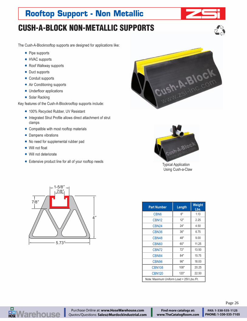
The Cush-A-Blockrooftop supports are designed for applications like:
Pipe supports
HVAC supports
Roof Walkway supports
Duct supports
Conduit supports
Air Conditioning supports
Solar Racking
Key features of the Cush-A-Blockrooftop supports include:
100% Recycled Rubber, UV Resistant
clamps
Compatible with most rooftop materials
Dampens vibrations
No need for supplemental rubber pad
Will not deteriorate
Extensive product line for all of your rooftop needs
4”
5.73”
7/8”
7/8”
1-5/8”
Typical Application Using Cush-a-Claw
Rooftop Support - Non Metallic
CUSH-A-BLOCK NON-METALLIC SUPPORTS
Part Number LengthWeight
Lbs.CBN6 6" 1.13
CBN12 12" 2.25
CBN24 24" 4.50
CBN36 36" 6.75
CBN48 48" 9.00
CBN60 60" 11.25
CBN72 72" 13.50
CBN84 84" 15.75
CBN96 96" 18.00
CBN108 108" 20.25
CBN120 120" 22.50
Note: Maximum Uniform Load = 250 Lbs./Ft.
Page 26

BREC
O Qu
ick
Disc
onne
ctGa
mm
a Pa
dsZ-
Clam
psBe
ta C
lam
psZ-
Stru
t Cha
nnel
sCu
sh-A
-Blo
ckLo
op &
Hos
e Cl
amps
Insu
latin
g Cl
ampi
ngCu
shio
ned
Clam
ping
Engineering Catalog www.zsi-inc.com – 27 –
CBS-Base Series
Part No. WeightUniform Load Capacity
(Lbs) *
CBS 4.80 lbs. 2,500 *
* This load is only for the capacity of the components in this assembly. Please consult roofing manufacturer or engineer for roof load capacity
The channel for Cush-A-Block support assemblies includes a variety
alloys including Aluminum, Stainless Steel both 304 & 316, PVC coated, Powder coated, Zinc Trivalent Chromium, Pre-Galvanized and Hot Dipped Galvanized.
Cush-A-Block features:
100% Recycled Rubber
Meets the Buy America Act and
Independent Laboratory Tested to the following
- Freeze/Thaw Environmental Simulation
Resistance to Freeze and Thaw
Dampens Vibrations
Compatible with most rooftop materials
Base Area Shown = 33.1 Sq. In. For use in bearing calculations
CUSH-A-BLOCK SUPPORTSCBS BASE SERIES, CBS-PRB SERIES WITH PIPE ROLLER
CUSH-A-BLOCK SUPPORTS
Cush-A-Block support applications:
Solar Racking
Pipe & Conduit supports
HVAC, Duct, Cable Tray supports
Air Conditioning supports
Roof Walkway supports
www.zsi-inc.com
Cush-A-Block
4"
107⁄8"
5"
Rooftop Support - Metallic
Page 27

– 28 – www.zsi-inc.com
CBS2D shown with two bases
The CBS Series provides a longer mounting surface with strut lengths up to 463
8"
www.zsi-inc.com
Cush-A-Block
www.zsi-inc.com
Cush-A-Block
www.zsi-inc.com
Cush-A-Block
www.zsi-inc.com
Cush-A-Block
Width
Strut LengthTotal Length
CUSH-A-BLOCK SUPPORTSCBS SERIES W/METAL CHANNEL
Standard strut mount pipe clamps are used to secure the pipes.
Note: Roof supports come pre-assembled
Rooftop Support - Metallic
CBS-Support With 1316" Pre-Galv. Steel Channel
Part No.
No. of Bases
Strut Length
Total Length
Weight (Lbs)
Uniform Load Capacity (Lbs) *
www.zsi-inc.com
Cush-A-Block
95⁄16"47⁄8"
107⁄8"5"
CBS1S 1 9.312" 10-78" 5.62 2,500 *
CBS2S 2 22.375" 24" 11.56 5,000 *
CBS3S 3 34.375" 36" 17.41 7,500 *
CBS4S 4 46.375" 48" 23.25 10,000 *
CBS-Support With 158" Pre-Galv. Steel Channel
www.zsi-inc.com
Cush-A-Block
95⁄16"
55⁄8"
107⁄8"5"
CBS1D 1 9.312" 10-78" 6.26 2,500 *
CBS2D 2 22.375" 24" 13.10 5,000 *
CBS3D 3 34.375" 36" 19.77 7,500 *
CBS4D 4 46.375" 48" 26.44 10,000 *
CBS Support With 2716" Pre-Galv. Steel Channel
95⁄16"
www.zsi-inc.com
Cush-A-Block
67⁄16"
107⁄8"5"
CBS1RD 1 9.312" 10-78" 6.69 2,500 *
CBS2RD 2 22.375" 24" 14.13 5,000 *
CBS3RD 3 34.375" 36" 21.35 7,500 *
CBS4RD 4 46.375" 48" 28.58 10,000 *
* This load is only for the capacity of the components in this assembly. Please consult roofing manufacturer or engineer for roof load capacity
Page 28

BREC
O Qu
ick
Disc
onne
ctGa
mm
a Pa
dsZ-
Clam
psBe
ta C
lam
psZ-
Stru
t Cha
nnel
sCu
sh-A
-Blo
ckLo
op &
Hos
e Cl
amps
Insu
latin
g Cl
ampi
ngCu
shio
ned
Clam
ping
Engineering Catalog www.zsi-inc.com – 29 –
CBS-CB–Bridge Series - Bridge Length Supports With 2 CBS Bases and Channel
Part No.Strut
LengthTotal
LengthWeight (Lbs)
Uniform Load Capacity (Lbs) *
CBS28BR 28" 29-34" 13.96 1,491*
CBS36BR 36" 37-34" 15.18 1,160*
CBS42BR 42" 43-34" 16.09 994*
CBS50BR 50" 51-34" 17.31 835*
CBS60BR 60" 61-34" 18.84 696*
* This load is only for the capacity of the components in this assembly. Please consult roofing manufacturer or engineer for roof load capacity
es - Bridge Length Supports With 2 CBS Bases and Channel
Strut Total Weight Uniform Load
www.zsi-inc.com
Cush-A-Block
www.zsi-inc.com
Cush-A-Block
Strut Length
Total Length
55⁄8"
5"
CUSH-A-BLOCK SUPPORTSCBS-BR BRIDGE SERIES WITH CHANNEL
CBS-EX-Extension Series Support With Threaded Rod Extension and Channel
Part No. HeightWeight (Lbs)
Uniform Load Capacity (Lbs) *
CBS8EX 8" 6.89 1,000 *
CBS12EX 12" 7.34 1,000 *
CBS16EX 16" 15.85 2,000 *
* This load is only for the capacity of the components in this assembly. Please consult roofing manufacturer or engineer for roof load capacity
www.zsi-inc.com
Cush-A-Block
Height
95⁄16"
5"
107⁄8"
13⁄16" Strut
www.zsi-inc.com
Cush-A-Block
www.zsi-inc.com
Cush-A-Block
24"Height
15⁄8" Strut
26"
5"
CUSH-A-BLOCK SUPPORTSCBS-CE SERIES WITH RAISED CHANNEL
CBS8EX, CBS12EX
CBS16EX
CBS8EX, CBS12EX
CBS16EX
Standard strut mount pipe clamps are used to secure the pipes.
Note: Roof supports come pre-assembled
Standard strut mount pipe clamps are used to secure the pipes.
Note: Roof supports come pre-assembled
Rooftop Support - Metallic
Page 29

– 30 – www.zsi-inc.com
Back-to-Back Pre-Galv Steel Channel
Part No.Base Width
Strut Width
Weight (Lbs)
Uniform Load Capacity (Lbs) *
CBS3RB 30-58" 24" 30.62 3,500 *
CBS4RB 42-58" 36" 32.96 3,250 *
* This load is only for the capacity of the components in this assembly. Please consult roofing manufacturer or engineer for roof load capacity
Pre-Galv Steel Channel
Part No.
Base Width
Strut Width
Base Length
Weight (Lbs)
Uniform Load Capacity (Lbs) *
CBS1RB 18-58" 12"
10-78"
19.35 3,000 *
CBS2RB 30-58" 24" 21.05 1,500 *
* This load is only for the capacity of the components in this assembly. Please consult roofing manufacturer or engineer for roof load capacity
StrutWidth
TotalWidth
www.zsi-inc.comCush-A
-Block
www.zsi-inc.comCush-A
-Block
107⁄8"
10"
www.zsi-inc.com
Cush-A-B
lock
www.zsi-inc.com
Cush-A-B
lock
StrutWidth
TotalWidth
107⁄8"
16"
CUSH-A-BLOCK SUPPORTSCBS-RB SERIES WITH RAISED BRIDGE MEDIUM SUPPORT
Standard strut mount pipe clamps are used to secure the pipes.
Note: Roof supports come pre-assembled
CUSH-A-BLOCK SUPPORTSCBS-RB SERIES WITH RAISED CHANNEL HEAVY SUPPORT
Standard strut mount pipe clamps are used to secure the pipes.
Note: Roof supports come pre-assembled
Rooftop Support - Metallic
Page 30

BREC
O Qu
ick
Disc
onne
ctGa
mm
a Pa
dsZ-
Clam
psBe
ta C
lam
psZ-
Stru
t Cha
nnel
sCu
sh-A
-Blo
ckLo
op &
Hos
e Cl
amps
Insu
latin
g Cl
ampi
ngCu
shio
ned
Clam
ping
Engineering Catalog www.zsi-inc.com – 31 –
CUSH-A-BLOCK SUPPORTSCBS-DS SERIES, ADJUSTABLE WIDTH DUCT SUPPORT
CUSH-A-BLOCK SUPPORTSCBS-PRB SERIES, WITH PIPE ROLLER
CBS-DS-Duct Support Series With Adjustable Width and Height
Part No.
WidthWeight (Lbs)
Uniform Load at Min. Width(Lbs) *Min. Max.
CBS1DS 19-14" 26-3
4" 29.61 1,909 *
CBS2DS 24-78" 39-7
8" 31.19 1,477 *
CBS3DS 38" 62-38" 34.87 967 *
CBS4DS 62-38" 103-5
8" 41.70 589 *
* This load is only for the capacity of the components in this assembly. Please consult roofing manufacturer or engineer for roof load capacity
The telescopic crossbeam provides easy size adjustments.
www.zsi-inc.comCush-A
-Block
www.zsi-inc.com
Cush-A-B
lock
Height
Width(min/max)
Duct
BaseLength
Standard strut mount pipe clamps are used to secure the pipes.
Note: Roof supports come pre-assembled
Note: Roof supports come pre-assembled
CBS-R-Roller-Series With 1-58" Pre-Galv. Steel Channel With Rollers
Part No.Pipe Size
(O.D.)Height
Overall Height to Roller Center
Weight (Lbs)
Uniform Load Capacity (Lbs) *
CBS1PRB 1" to 2"8"
7"
9.03 2,500 *
CBS2PRB 2" to 3-12" 8.70 2,500 *
CBS3PRB 4" to 6" 8-18" 9.21 2,500 *
CBS4PRB 8" to 10" 9-78" 8-1
4" 14.11 2,500 *
* This load is only for the capacity of the components in this assembly. Please consult roofing manufacturer or engineer for roof load capacity
www.zsi-inc.comCush-A
-Block
Height
Roller Size
107⁄8"
9.312"
5"
Rooftop Support - Metallic
Page 31

– 32 – www.zsi-inc.com
PYTHON SERIESSTRONG:hose clamps keep their grip on the hose and can be reused. Rolled up band edges ensure a smooth transition between band and hose. Hexagonal screw head with drive slot makes for easy accessibility.
The Python II provides greater clamping force with less trouble than heavy-duty T-Bolt type clamps.
Lower cost than T-Bolts with superb performance.
Thicker band for greater tensile strength.
Greater clamping range than T-Bolt 11⁄2" clamping range over 2" diameter
Zinc plated or 304, 316, or 430 stainless steel
Non perforated band with embossed threads safely seals without cutting the hose.
Python Cable Clamps
Python – Zinc Plated, or Stainless Steel Type 304
Zinc Plated
Part No.
Stainless Steel
Part No.
SAE Size
Clamping Range
in. mm
PY-03 PY-30 3 5 ⁄16 - 9 ⁄16 8-14
PY-04 PY-40S 4 7 ⁄16 - 11 ⁄16 11-17
PY-06 PY-60 6 1 ⁄2 - 13 ⁄16 13-20
PY-08 PY-80S 8 5 ⁄8 - 15 ⁄16 15-24
PY-10 PY-100 10 3 ⁄4 - 1-1 ⁄8 19-28
PY-12 PY-120 12 7 ⁄8 - 1-1 ⁄4 22-32
PY-16 PY-160 16 1-1 ⁄16 - 1-1 ⁄2 26-38
PY-20 PY-200 20 1-1 ⁄4 - 1-3 ⁄4 32-44
PY-24 PY-240 24 1-1 ⁄2 - 2 38-50
PY-28 PY-280 28 1-3 ⁄4 - 2-1 ⁄4 44-56
PY-32 PY-320 32 2 - 2-9 ⁄16 50-65
PY-40 PY-400 40 2-5 ⁄16 - 3 58-75
PY-44 PY-440 44 2-11 ⁄16 - 3-3 ⁄8 68-85
PY-52 PY-520 52 3 - 3-3 ⁄4 77-95
PY-64 PY-640 64 3-7 ⁄16 - 4-7 ⁄16 87-112
PY-80 PY-800 80 4-1 ⁄8 - 5-7 ⁄16 104-138
PY-96 PY-960 96 5-1 ⁄8 - 6-1 ⁄2 130-165
PY-104 PY-1040 104 5-7 ⁄8 - 7-1 ⁄8 150-180
PY-122 PY-1220 122 6-7 ⁄8 - 8-1 ⁄8 175-205
PY-138 PY-1380 138 7-7 ⁄8 - 9-1 ⁄8 200-231
PY-154 PY-1540 154 8-7 ⁄8 - 10-1 ⁄16 226-256
PY-170 PY-1700 170 9-7 ⁄8 - 11-1 ⁄8 251-282
PY-186 PY-1860 186 10-7 ⁄8 - 12-1 ⁄8 277-307
PYTHON II – Stainless Steel Type 316
Part No.Clamping Range
in. mm
PY-331 5 ⁄16 - 9 ⁄16 8 -14
PY-431 7 ⁄16 - 11 ⁄16 11-17
PY-631 1 ⁄2 - 13 ⁄16 13-20
PY-831 5 ⁄8 - 15 ⁄16 15-24
PY-1031 3 ⁄4 - 1-1 ⁄8 19-28
PY-1231 7 ⁄8 - 1-1 ⁄4 22-32
PY-1631 1-1 ⁄16 - 1-1 ⁄2 26-38
PY-2031 1-1 ⁄4 - 1-3 ⁄4 32-44
PY-2431 1-1 ⁄2 - 2 38-50
PY-2831 1-1 ⁄4 - 2-1 ⁄4 32-57
PY-3231 1 ⁄2 - 2-1 ⁄2 38-64
PY-3631 1-3 ⁄4 - 2-3 ⁄4 44-70
PY-4031 2 - 3 51-76
PY-4431 2-1 ⁄4 - 3-1 ⁄4 57-83
PY-4831 2-1 ⁄2 - 3-1 ⁄2 64-89
PY-5231 2-3 ⁄4 - 3-3 ⁄4 70-95
PY-5631 3 - 4 76-102
PY-6031 3-1 ⁄4 - 4-1 ⁄4 83-108
PY-6431 3-1 ⁄2 - 4-1 ⁄2 89-114
PY-7231 3-1 ⁄2 - 5 89 -127
PY-8031 4 - 5-1 ⁄2 102-140
PY-8831 4 - 1 ⁄2-6 114-152
PY-9631 5 - 6-1 ⁄2 127-165
PY-10431 5-1 ⁄2 - 7 140-178
PY-11231 6 - 7-1 ⁄2 152-191
PY-12031 6-1 ⁄2 - 8 165-203
PY-12831 7 - 8-1 ⁄2 178-216
PY-13831 7-5 ⁄8 - 9-1 ⁄8 194-232
PY-15431 8-5 ⁄8 - 10-1 ⁄8 219-257
PY-17031 9-5 ⁄8 - 11-1 ⁄8 244-283
PY-18631 10-5 ⁄8 - 12-1 ⁄8 270-308 Page 32

BREC
O Qu
ick
Disc
onne
ctGa
mm
a Pa
dsZ-
Clam
psBe
ta C
lam
psZ-
Stru
t Cha
nnel
sCu
sh-A
-Blo
ckLo
op &
Hos
e Cl
amps
Insu
latin
g Cl
ampi
ngCu
shio
ned
Clam
ping
Engineering Catalog www.zsi-inc.com – 33 –
QUICK-CLIP
(See Page 19)
STRUT PRODUCTSZSi offers a line of standard strut channel and a variety of clamps tailored for use with strut. Cush-A-Clamp®, Cush-A-Therm™, and Porce-A-Clamp™ provide cushioned clamping solutions.
1-5 8"13 16"7 8"1"
All Z-Strut is 1-5 8" Wide, With 7 8" opening
Z1625 Z1000 Z875 Z8125
CUSH-A-CLAMP®
(See Page 6)
PORCE-A-CLAMP™
(See Page 12)
CUSH-A-CLIP
(See Page 8)
CUSH-A-GRIP
(See Page 8)
CUSH-A-CLAW
(See Page 7)
CUSH-A-CLICK
(See Page 19)
ZSi's family of non-metallic strut clamps allow quick and easy attachment of pipe, tube, and hose to Z-Strut support channels and are corrosion resistant. They are all a great and cost effective alternative to metallic clamps.
ZSi's family of cushioned clamps presented earlier in the catalog offer solutions for isolation of the pipes from vibration or thermal transfers.
are available.
Complementing products are offered for quick connection of pipe, tube and hose to strut.
SADDLE-UP
(See Page 13)
CUSH-A-THERM™
(See Page 14)
Z-Strut and Z-strut Clamps
Page 33

– 34 – www.zsi-inc.com
Z1625 PGSolid ChannelPre-Galvanized
Z1625 SH PGSlotted ChannelPre-Galvanized
Z1625 SSSolid Channel304 Stainless Steel
Z1625 EASolid ChannelExtruded Aluminum
Z1625 SERIES1 5 8"
1 5 8"
7 8"
MATERIAL/FINISH
Pre-galvanized – Steel conforming to ASTM A653 GR 33.
Z1000 SERIES
1"
1 5 8"7 8"
MATERIAL/FINISH
Pre-galvanized – Steel conforming to ASTM A653 GR 33.Z1000 PGSolid ChannelPre-Galvanized
Z1000 PGSolid Channel304 Stainless Steel
Z-Strut™ Channel
Z1625 - 15/8" x 15/8" Channel, 12 Ga.Solid Channel Slotted Channel
LengthSteel
Channel Wt. Each
Aluminum Channel Wt. Each
Pre-galvanized Part No.
Stainless Steel Type 304 Part No.
Extruded Aluminum Part No.
Pre-galvanized Part No.
Z1625-06PG Z1625-06SS Z1625-06EA Z1625SH-06PG 0' – 6" 0.95 0.38Z1625-12PG Z1625-12SS Z1625-12EA Z1625SH-12PG 1' – 0" 1.90 0.76Z1625-18PG Z1625-18SS Z1625-18EA Z1625SH-18PG 1' – 6" 3.04 1.22Z1625-24PG Z1625-24SS Z1625-24EA Z1625SH-24PG 2' – 0" 3.80 1.52Z1625-30PG Z1625-30SS Z1625-30EA Z1625SH-30PG 2' – 6" 4.94 1.98Z1625-36PG Z1625-36SS Z1625-36EA Z1625SH-36PG 3' – 0" 5.70 2.28Z1625-42PG Z1625-42SS Z1625-42EA Z1625SH-42PG 3' – 6" 6.84 2.74Z1625-48PG Z1625-48SS Z1625-48EA Z1625SH-48PG 4' – 0" 7.60 3.04Z1625-54PG Z1625-54SS Z1625-54EA Z1625SH-54PG 4' – 6" 8.74 3.50Z1625-60PG Z1625-60SS Z1625-60EA Z1625SH-60PG 5' – 0" 9.50 3.80
Z1000 - 15/8" x 1" Channel, 12 Ga.Solid Channel
Pre-galvanized Part No.
Stainless Steel Type 304 Part No.
Length Weight
Z1000-06PG Z1000-06SS 0' – 6" 0.70Z1000-12PG Z1000-12SS 1' – 0" 1.40Z1000-18PG Z1000-18SS 1' – 6" 2.24Z1000-24PG Z1000-24SS 2' – 0" 2.80Z1000-30PG Z1000-30SS 2' – 6" 3.64Z1000-36PG Z1000-36SS 3' – 0" 4.20Z1000-42PG Z1000-42SS 3' – 6" 5.04Z1000-48PG Z1000-48SS 4' – 0" 5.60Z1000-54PG Z1000-54SS 4' – 6" 6.44Z1000-60PG Z1000-60SS 5' – 0" 7.00
Page 34

BREC
O Qu
ick
Disc
onne
ctGa
mm
a Pa
dsZ-
Clam
psBe
ta C
lam
psZ-
Stru
t Cha
nnel
sCu
sh-A
-Blo
ckLo
op &
Hos
e Cl
amps
Insu
latin
g Cl
ampi
ngCu
shio
ned
Clam
ping
Engineering Catalog www.zsi-inc.com – 35 –
Z875 SERIES
7 8"
1 5 8"7 8"
Z875 PGSlotted ChannelPre-Galvanized
Z875 PGSolid ChannelPre-Galvanized
MATERIAL/FINISH
Pre-galvanized – Steel conforming to ASTM A653 GR 33.
Z8125 PGSolid ChannelPre-Galvanized
Z8125 PGSolid ChannelStainless Steel
Z8125 PGSolid ChannelExtruded Aluminum
Z8125 PGSlotted ChannelPre-Galvanized
Z8125 SERIES1 5 8"
7 8"13 16"
MATERIAL/FINISH
Pre-galvanized – Steel conforming to ASTM A653 GR 33.
Z-Strut™ Channel
Z875 - 15/8" x 7/8" Channel, 12 Ga.Solid Channel Slotted Channel
Length Wt. EachPre-galvanized Part No.
Pre-galvanized Part No.
Z875-06PG Z875SH-06PG 0' – 6" 0.68Z875-12PG Z875SH-12PG 1' – 0" 1.35Z875-18PG Z875SH-18PG 1' – 6" 2.16Z875-24PG Z875SH-24PG 2' – 0" 2.70Z875-30PG Z875SH-30PG 2' – 6" 3.51Z875-36PG Z875SH-36PG 3' – 0" 4.05Z875-42PG Z875SH-42PG 3' – 6" 4.86Z875-48PG Z875SH-48PG 4' – 0" 5.40Z875-54PG Z875SH-54PG 4' – 6" 6.21Z875-60PG Z875SH-60PG 5' – 0" 6.75
Z8125 - 15/8" x 13/16" Channel, 14 Ga.
Solid ChannelSlotted
Channel
LengthSteel
Channel Wt. Each
Aluminum Channel Wt. EachPre-galvanized
Part No.
Stainless Steel Type 304 Part No.
Extruded Aluminum Part No.
Pre-galvanized Part No.
Z8125-06PG Z8125-06SS Z8125-06EA Z8125SH-06PG 0' – 6" 0.49 0.23Z8125-12PG Z8125-12SS Z8125-12EA Z8125SH-12PG 1' – 0" 0.97 0.45Z8125-18PG Z8125-18SS Z8125-18EA Z8125SH-18PG 1' – 6" 1.55 0.72Z8125-24PG Z8125-24SS Z8125-24EA Z8125SH-24PG 2' – 0" 1.94 0.90Z8125-30PG Z8125-30SS Z8125-30EA Z8125SH-30PG 2' – 6" 2.52 1.17Z8125-36PG Z8125-36SS Z8125-36EA Z8125SH-36PG 3' – 0" 2.91 1.35Z8125-42PG Z8125-42SS Z8125-42EA Z8125SH-42PG 3' – 6" 3.49 1.62Z8125-48PG Z8125-48SS Z8125-48EA Z8125SH-48PG 4' – 0" 3.88 1.80Z8125-54PG Z8125-54SS Z8125-54EA Z8125SH-54PG 4' – 6" 4.46 2.07Z8125-60PG Z8125-60SS Z8125-60EA Z8125SH-60PG 5' – 0" 4.85 2.25
Page 35

– 36 – www.zsi-inc.com
Beta Clamps are ideal for clamping pipe, tube, hose, and electric cables. They are an economical and easy way of securing them in all types of terrestrial, marine, O.E.M. and Industrial applications. Thanks to the advanced features and the breadth and depth of our product offering, Beta Clamps are used in all areas of industrial, mobile and
press technology, instrumentation and control technology and many more.
Beta Clamps offer shock-absorption, vibration dampening and noise reducing properties.
Beta Clamps feature a practical and economical design which make for quick, easy pipe installation and layout.
Using weldable plates, it’s easy to anchor the clamps to machinery and steel work.
Fast, safe, economic installation and service in piping system.
Upper and lower clamp half are identical.
Ribs in clamp bore are designed to absorb shock and vibra-tion in the direction of the tube axis.
Due to their design the clamps can be easily cleaned.
CLAMP BODY
Aluminum is available for use in high heat applications
CLAMP COMPONENTS – The other metallic components of the clamps are manufactured in:
Lower and upper plates: steel, stainless steel type 304
Screw bolts: steel, S40C, stainless steel type 304
Other metallic on request.
Install by welding theweld plate to existing steel
Attach to C-Rail usingZSI C-Rail Nuts
Attach to Z-Strut Channelusing our exclusive Z-StrutChannel Adapter Nut
ZSi offers an installation option for all of your application needs.
COMMON WELDED METHOD
DIN RAIL MOUNTED
Z-STRUT MOUNTED
Beta Clamps - Overview
Page 36

BREC
O Qu
ick
Disc
onne
ctGa
mm
a Pa
dsZ-
Clam
psBe
ta C
lam
psZ-
Stru
t Cha
nnel
sCu
sh-A
-Blo
ckLo
op &
Hos
e Cl
amps
Insu
latin
g Cl
ampi
ngCu
shio
ned
Clam
ping
Engineering Catalog www.zsi-inc.com – 37 –
BETA STANDARD BETA HEAVY
BETA TWIN BETA SMOOTHIE
BETA SMOOTHIE TWIN BETA SPECIAL METALS (ALUMINUM, STAINLESS STEEL)
BETA RUBBER INSERTS BETA ADAPTER
For standard hydraulics and systems with less than 1500 PSI without dynamic loads
Polypropylene cushion
Steel components
For systems with greater than 1500 PSI operating pressure, operations with pressure surges, and applications with wide
Absorbs high levels of shock, noise, and vibration
Polypropylene cushion & steel components
For standard hydraulics, general pipe construction and electrical cables
Polypropylene cushion
Steel components
Reduces wear on hose connection caused by vibration and surge.
Chamfered and smooth core protects hose cover and extends hose life.
Uses Beta Standard hardware
Polypropylene cushion
Steel components
Reduces wear on hose connection caused by vibration and surge.
Chamfered and smooth core protects hose cover and extends hose life.
Uses Beta Twin hardware
Polypropylene cushion
Steel components
Aluminum cushions with steel components are used in high heat applications up to 500°
Stainless steel clamp hardware with polypropylene cushion are used in applications where external corrosion is a concern.
Allows a clamping junction to be inserted into hydraulic lines.
The adapter body is offered in two sizes for use with the Z-Clamp adapter inserts.
Available in standard and heavy
One cushion block provides
cushioning.
Smooth bore core can be used on hose, or for vibration reduction
Beta Clamps - Overview
Page 37

– 38 – www.zsi-inc.com
BETA CLAMPSSTANDARD SERIES
BETA STANDARD SERIES
Recommended for systems with less than 1500 PSI without dynamic loads.
Use for standard hydraulics, general pipe construction, electrical cables, and general duty piping applications subject to moderate levels of shock and vibration.
Aluminum cushions and are used in higher heat applications up to 500 Degrees.
INSTALLATION - Refer to pages 115-117 for complete installation guide.
S C
Assembly Types
B R SI Z
Size
A2
A1
H1
1.2"
3mm (.12")Thick
3mm (.12") Thick
H2
A3
Steel w/ Polypropylene Cushion Steel w/
Aluminum Cushion
Beta Clamps - Standard
GroupPartNo. *
Tube Size
Pipe Size
Metric Size
Dimensions - inch (mm) Wt⁄ 100
BoltA1 A2 A3 H1 H2
S1
S-1004 1⁄4 – –
0.78 1.34 1.41 0.62 1.25 17
1 ⁄4"-20 x 11 ⁄4"
S-1006 3 ⁄8 – –
SM-1006 – – 6mm
S-1007 – 1 ⁄8 –
SM-1008 – – 8mm
SM-1012 – – 12mm
S2
S-2008 1 ⁄2 – –
1.02 1.57 1.65 0.76 1.54 20
1 ⁄4"-20 x 13 ⁄8"
S-2009 – 1 ⁄4 –
S-2010 5 ⁄8 – –
S-2011 – 3 ⁄8 –
SM-2014 – – 14mm
SM-2015 – – 15mm
SM-2018 – – 18mm
S3
S-3012 3 ⁄4 – –
1.29 1.96 2.04 0.80 1.61 24
1 ⁄4"-20 x 11 ⁄2"
S-3014 – 1 ⁄2 –
S-3015 7 ⁄8 – –
S-3016 – –
SM-3020 – – 20mm
SM-3025 – – 25mm
S4S-4017 – 3 ⁄4 –
1.57 2.28 2.36 0.94 1.88 30
1 ⁄4"-20 x 13 ⁄4"S-4018 11 ⁄8 – –
SM-4030 – – 30mm
S5
S-5020 11 ⁄4 – –
2.04 2.75 2.83 1.25 2.52 40
1 ⁄4"-20 x 21 ⁄2"
S-5021 – –
S-5024 11 ⁄2 – –
S-5027 – 11 ⁄4 –
SM-5035 – – 35mm
S6S-6028 13 ⁄4 – –
2.59 3.38 3.46 1.41 2.83 47
1 ⁄4"-20 x 23 ⁄4"S-6030 – 11 ⁄2 –
S-6032 – –
S7
S-7038 – –
3.70 4.75 4.81 2.00 4.05 97
1 ⁄4"-20 x 4"
S-7036 21 ⁄4 – –
S-7040 21 ⁄2 – –
S-7044 23 ⁄4 – –
S-7048 – –
SUFFIX
*For additional sizes contact factory. Note: Add assembly type to part number. Example: S-1004S-SS provides the complete assembly as shown with stainless steel components.
Components Cushion Examplenone Steel S-1004S-AL Steel Aluminum S-1004S-AL-SS Stainless Steel S-1004S-SS
Page 38

BREC
O Qu
ick
Disc
onne
ctGa
mm
a Pa
dsZ-
Clam
psBe
ta C
lam
psZ-
Stru
t Cha
nnel
sCu
sh-A
-Blo
ckLo
op &
Hos
e Cl
amps
Insu
latin
g Cl
ampi
ngCu
shio
ned
Clam
ping
Engineering Catalog www.zsi-inc.com – 39 –
SWP-1 Weld Plate
SCP-1 Cover Plate
(2) SHB-1 Hex Bolts
CushionsS1004-C
11 mm
2 mm28 mm11 mm
Beta Clamps - Standard
STANDARD SERIES COVER PLATE STANDARD SERIES SAFETY PLATESCP-1 Use with Group S1 SP-1 Use with Group S1SCP-2 Use with Group S2 SP-2 Use with Group S2SCP-3 Use with Group S3 SP-3 Use with Group S3SCP-4 Use with Group S4 SP-4 Use with Group S4SCP-5 Use with Group S5 SP-5 Use with Group S5SCP-6 Use with Group S6 SP-6 Use with Group S6SCP-7 Use with Group S7
HEX BOLT (Two required per assembly) STANDARD SERIES CAP SCREW (Two required per assembly)SHB-1 Use with Group S1 SC-1 Use with Group S1SHB-2 Use with Group S2 SC-2 Use with Group S2SHB-3 Use with Group S3 SC-3 Use with Group S3SHB-4 Use with Group S4 SC-4 Use with Group S4SHB-5 Use with Group S5 SC-5 Use with Group S5SHB-6 Use with Group S6 SC-6 Use with Group S6SHB-7 Use with Group S7
STACKING BOLTS (Two required per assembly) C-RAIL NUT (Two required per assembly)SB-1 Use with Group S1 SRN-1-6 1 ⁄4" nut, Use with SCR RailSB-2 Use with Group S2SB-3 Use with Group S3SB-4 Use with Group S4SB-5 Use with Group S5SB-6 Use with Group S6
STANDARD SERIES WELD PLATE C-RAILSWP-1 Use with Group S1 SCR-1SWP-2 Use with Group S2 SCR-2SWP-3 Use with Group S3SWP-4 Use with Group S4SWP-5 Use with Group S5SWP-6 Use with Group S6SWP-7 Use with Group S7
STRUT NUT - For connection to Z-Strut Channel (Two required per assembly)
Z-Strut
ZSA1-8 Use with Groups S1-S8 Z1625 1-5/8" x 1-5/8"
Z8125 1-5/8" x 13/16"
Z1000 1-5/8" x 1"
Z875 1-5/8" x 7/8"
ORDERING EXAMPLE
S-1004-S
Assembly Includes
Quantity Part No. Description
1 Each SWP-1 Weld Plate 1 Each SCP-1 Cover Plate 2 Each SHB-1 Hex Bolts
1 set S1004-C Cushions
Page 39

– 40 – www.zsi-inc.com
BETA HEAVY SERIES
Recommended systems with greater than 1500 PSI operating pressure, operations with pressure surges, and applications with wide temperature
Absorbs high levels of shock, noise, and vibration Cushions are polypropylene (Green
Aluminum cushions and are used in higher heat applications up to 500 Degrees.
INSTALLATION - Refer to pages 115-117 for complete installation guide.
BETA CLAMPSHEAVY SERIES
Steel w/ Polypropylene Cushion
Steel w/ Aluminum Cushion
H1
B1
B1
A2
Size
T
T
H2
A3
A1
S C
Assembly Types
B R D
Beta Clamps - Heavy
GroupPart No.
Tube Size
Pipe Size
Dimensions-inch(mm) Wt⁄ 100
Hex BoltA1 A2 A3 B1 H1 H2 T
H3
H-3004 1 ⁄4 –
1.29 2.87 2.16 1.18 0.94 1.88 0.31
65
3 ⁄8"-16 x 1-3 ⁄4"
H-3006 3 ⁄8 – 65
H-3007 – 1 ⁄8 65
H-3008 1 ⁄2 – 65
H-3009 – 1 ⁄4 65
H-3010 5 ⁄8 – 65
H-3011 – 3 ⁄8 65
H4
H-4012 3 ⁄4 –
1.77 3.34 2.75 1.18 1.25 2.51 0.31
83
3 ⁄8"-16 x 2-1 ⁄4"
H-4014 – 1 ⁄2 82
H-4015 7 ⁄8 – 83
H-4016 – 83
H-4017 – 3 ⁄4 83
H5
H-5020 11 ⁄4 –
2.36 3.93 3.30 1.18 1.49 2.99 0.31
1043 ⁄8"-16 x
2-3 ⁄4"H-5021 – 104
H-5024 11 ⁄2 – 103
H-5027 – 11 ⁄4 103
H6
H-6028 13 ⁄4 –
3.54 5.90 4.52 1.77 2.16 4.33 0.39
266
1 ⁄2"-13 x 4"
H-6030 – 11 ⁄2 276
H-6032 – 267
H-6034 21 ⁄4 – 266
H-6038 23 ⁄8 267
H-6040 21 ⁄2 – 264
H7
H-7044 23 ⁄4 –
4.80 7.08 5.98 2.36 2.75 5.51 0.39
510
5 ⁄8"-11x 5-1 ⁄4"
H-7046 – 21 ⁄2 525
H-7050 – 506
H-7056 – 495
H-7057 31 ⁄2 – 510
H8 H-8072 –6.61 8.86 8.07 3.15 3.94 7.87 0.59
6353 ⁄4"-10 x
7-1 ⁄2"
H9H-9089 – 8.07 10.63 9.92 3.54 4.53 9.06 0.59 625 7 ⁄8"-9 x
8-1 ⁄4"H-9106 – 635
SUFFIX
*For additional sizes contact factory. Note: Add assembly type to part number. Example: H-3004S-SS provides the complete assembly as shown with stainless steel components.
Components Cushion
NONE Steel H-3004S
-AL Steel Aluminum H-3004S-AL
-SS Stainless Steel H-3004S-SS Page 40

BREC
O Qu
ick
Disc
onne
ctGa
mm
a Pa
dsZ-
Clam
psBe
ta C
lam
psZ-
Stru
t Cha
nnel
sCu
sh-A
-Blo
ckLo
op &
Hos
e Cl
amps
Insu
latin
g Cl
ampi
ngCu
shio
ned
Clam
ping
Engineering Catalog www.zsi-inc.com – 41 –
HWP-3 Weld Plate
HCP-3 Cover Plate
(2) HHB-3 Hex Bolts
Cushions H3011-C
22 mm
5 mm40 mm
13 mm
Beta Clamps - Heavy
HEAVY SERIES COVER PLATE HEAVY SERIES SAFETY PLATEC-RAIL NUTS (Two required per single
assembly)
HCP-3 Use w/Group H3 HSP-3 Use w/Group H3HRN-3-5
3 ⁄8" nut, Use w/Groups H3-H5 HCP-4 Use w/Group H4 HSP-4 Use w/Group H4
HCP-5 Use w/Group H5 HSP-5 Use w/Group H5HRN-6
7 ⁄16" nut, Use w/Group H6HCP-6 Use w/Group H6 HSP-6 Use w/Group H6
HCP-7 Use w/Group H7 HSP-7 Use w/Group H7 Note: Rail mounted stacking kit is only available on groups
H3, H4, and H5HCP-8 Use w/Group H8 HSP-8 Use w/Group H8
HCP-9 Use w/Group H9 HSP-9 Use w/Group H9
HEAVY SERIES HEX BOLTS (Two required per single assembly)
HEAVY SERIES STACKING BOLTS (Two required per single assembly)
C-RAIL
HHB-3 Use w/Group H3 HSB-3 Use w/Group H3 HCR-1
HHB-4 Use w/Group H4 HSB-4 Use w/Group H4 HCR-2
HHB-5 Use w/Group H5 HSB-5 Use w/Group H5
HHB-6 Use w/Group H6 HSB-6 Use w/Group H6
HHB-7 Use w/Group H7 HSB-7 Use w/Group H7
HHB-8 Use w/Group H8 HSB-8 Use w/Group H8
HHB-9 Use w/Group H9 HSB-9 Use w/Group H9
HEAVY SERIES WELD PLATE HEAVY SERIES DOUBLE WELD PLATE HEAVY SERIES DOUBLE COVER PLATE
HWP-3 Use w/Group H3 HDP-3 Use w/Group H3 DCP-3 Use w/Group H3
HWP-4 Use w/Group H4 HDP-4 Use w/Group H4 DCP-4 Use w/Group H4
HWP-5 Use w/Group H5 HDP-5 Use w/Group H5 DCP-5 Use w/Group H5
HWP-6 Use w/Group H6 HDP-6 Use w/Group H6 DCP-6 Use w/Group H6
HWP-7 Use w/Group H7 HDP-7 Use w/Group H7 DCP-7 Use w/Group H7
HWP-8 Use w/Group H8
HWP-9 Use w/Group H9
ORDERING EXAMPLE
H3004-S
Assembly Includes
Quantity Part No. Description
1 Each HWP-3 Weld Plate 1 Each HCP-3 Cover Plate 2 Each HHB-3 Hex Bolts 1 set H3011-C Cushions
Page 41
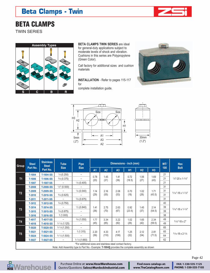
– 42 – www.zsi-inc.com
BETA CLAMPSTWIN SERIES
S C
Assembly Types
B R
H1
H2H3
Size Size
A1A3A2
5mm(.2")
30mm(1.2")
BETA CLAMPS TWIN SERIES are ideal for general-duty applications subject to moderate levels of shock and vibration. Cushions in this series are Polypropylene
Call factory for additional sizes and cushion materials
INSTALLATION - Refer to pages 115-117 for complete installation guide.
Beta Clamps - Twin
GroupSteel
Part No.
Stainless Steel
Part No.
Tube Size
Pipe Size
Dimensions - inch (mm) WT⁄ 100
Hex Bolt
A1 A2 A3 H1 H2 H3
T1T-1004 T-1004-SS 1 ⁄4 –
0.78 1.45 1.41 0.72 1.06 1.69 21
1 ⁄4"-20 x 1-3 ⁄8"T-1006 T-1006-SS 3 ⁄8 – 21
T-1007 T-1007-SS – 1 ⁄8 21
T2
T-2008 T-2008-SS 1 ⁄2" (0 –
1.14 2.16 2.08 0.70 1.02 1.71
31
5 ⁄16"-18 x 1-3 ⁄8"T-2009 T-2009-SS – 1 ⁄4 31
T-2010 T-2010-SS 5 ⁄8 – 31
T-2011 T-2011-SS – 3 ⁄8 31
T3
T-3012 T-3012-SS 3 ⁄4 (0 –
1.41 2.75 2.63 0.92 1.45 2.14
40
5 ⁄16"-18 x 1-3 ⁄4"T-3014 T-3014-SS – 1 ⁄2 39
T-3015 T-3015-SS 7 ⁄8 – 39
T-3016 T-3016-SS – 38
T4T-4017 T-4017-SS – 3 ⁄4 (1 1.77 3.34 3.22 1.02 1.65 2.34 49
5 ⁄16"-18 x 2"T-4018 T-4018-SS 1-1 ⁄8 – 49
T5
T-5020 T-5020-SS 1-1 ⁄4 (1 –
2.20 4.33 4.17 1.25 2.12 2.81
65
5 ⁄16-18 x 2-3 ⁄8T-5021 T-5021-SS – 65
T-5024 T-5024-SS 1-1 ⁄2 – 64
T-5027 T-5027-SS – 1-1 ⁄4 62
*For additional sizes and stainless steel contact factory. Note: Add Assembly type to Part No.- Example: T-1004S provides the complete assembly as shown
Page 42

BREC
O Qu
ick
Disc
onne
ctGa
mm
a Pa
dsZ-
Clam
psBe
ta C
lam
psZ-
Stru
t Cha
nnel
sCu
sh-A
-Blo
ckLo
op &
Hos
e Cl
amps
Insu
latin
g Cl
ampi
ngCu
shio
ned
Clam
ping
Engineering Catalog www.zsi-inc.com – 43 –
(1) TB-1 Hex Bolt
TC-1 Cover Plate
Cushions T2008-S
TP-1 Weld Plate
Beta Clamps - Twin
TWIN SERIES COVER PLATE TWIN SERIES SAFETY PLATE
TC-1 Use with Group T1 TSP-1 Use with Group T1
TC-2 Use with Group T2 TSP-2 Use with Group T2
TC-3 Use with Group T3 TSP-3 Use with Group T3
TC-4 Use with Group T4 TSP-4 Use with Group T4
TC-5 Use with Group T5 TSP-5 Use with Group T5
TWIN HEX BOLT C-RAIL NUT
TB-1 Use with Group T1 SRN-1-6 1 ⁄4" Nut,
TB-2 Use with Group T2 Use with Group T1
TB-3 Use with Group T3 TRN-2-5 5 ⁄16" Nut,
TB-4 Use with Group T4 Use with Group T2 to T5
TB-5 Use with Group T5
TWIN STACKING BOLT C-RAIL
TSB-1 Use with Group T1 SCR-1
TSB-2 Use with Group T2 SCR-2
TSB-3 Use with Group T3
11 mm
2 mm28 mm11 mm
TSB-4 Use with Group T4
TSB-5 Use with Group T5
TWIN SERIES WELD PLATE
TP-1 Use with Group T1
TP-2 Use with Group T2
TP-3 Use with Group T3
TP-4 Use with Group T4
TP-5 Use with Group T5
ORDERING EXAMPLE
T2008-S Assembly Includes
Quantity Part No. Description
1 Each TP-1 Weld Plate 1 Each TC-1 Cover Plate 1 Each TB-1 Hex Bolts 1 set T2008-S Cushions
Page 43

– 44 – www.zsi-inc.com
Beta "Smoothie" is ideal for general-duty applications where there is a need to reduce wear on hose connection caused by vibration and surge.
Chamfered and smooth core protects hose cover and extends the life of the hose
Uses Standard Beta hardware
Reduces wear on hose connection caused by vibration and surge
INSTALLATION - Refer to pages 115-117 for complete installation guide.
BETA “SMOOTHIE” STANDARD SERIES
S C
Assembly Types
B R SI Z
Size
A2A1
H1
3 mm(.12")
Plate is 30mm (1.2") x “A3”x 3 mm (.12") Thick
H2
BETA “SMOOTHIE” TWIN SERIES
Beta "Smoothie" is ideal for general-duty applications where there is a need to reduce wear on hose connection caused by vibration and surge.
Chamfered and smooth core protects hose cover and extends the life of the hose
Uses Standard Beta Twin hardware
Reduces wear on hose connection caused by vibration and surge
INSTALLATION - Refer to pages 115-117 for complete installation guide.
S C
Assembly Types
B R
H1
H2H3
Size Size
A1A3
Plate is 30mm (1.2") x “A2”x 5 mm (.2") Thick
Beta Clamps - "Smoothie"
GroupPart No.
SAE 100R1 Hose Size
Dimensions (Inches)WT⁄ 100
BoltA1 A2 A3 H1 H2
S2S-2004H 1 ⁄4 1.02 1.57 1.65 0.76 1.535 20 1 ⁄4 – 20
x 13 ⁄8S-2006H 3 ⁄8" (0.69 1.02 1.57 1.65 0.76 1.535 20
S3S-3008H 1 ⁄2 1.29 1.96 2.04 0.80 1.61 25 1 ⁄4 – 20
x 11 ⁄2S-3010H 5 ⁄8" (0.93 1.29 1.96 2.04 0.80 1.61 25
S4 S-4012H 3 ⁄4 1.57 2.28 2.36 0.94 1.88 291 ⁄4 – 20 x 13 ⁄4
S5 S-5016H 2.05 2.75 2.83 1.25 2.52 391 ⁄4 – 20 x 21 ⁄2
*For additional sizes and stainless steel contact factory. Note: Add Assembly type to Part No.- Example: S-2004HS provides the
complete assembly as shown
GroupPart No.
SAE 100R1 Hose Size
Dimensions (Inches) WT⁄ 100
BoltA1 A2 A3 H1 H2 H3
T2T-2004H 1 ⁄4 1.14 2.16 2.08 0.70 1.02 1.71 31 5 ⁄16 – 18
x 13 ⁄8T-2006H 3 ⁄8" (0.69 1.14 2.16 2.08 0.70 1.02 1.71 31
T3 T-3008H 1 ⁄2 1.41 2.75 2.63 0.92 1.45 2.14 395 ⁄16 – 18
x 13 ⁄4
T4T-4010H 5 ⁄8 1.77 3.34 3.22 1.02 1.65 2.34 49 5 ⁄16 – 18
x 2T-4012H 3 ⁄4" (1.10 1.77 3.34 3.22 1.02 1.65 2.34 49
T5 T-5016H 2.2 4.33 4.17 1.25 2.12 2.81 655 ⁄16 – 18
x 23 ⁄8*For additional sizes and stainless steel contact factory.
Note: Add Assembly type to Part No.- Example: T-2004HS provides the complete assembly as shown Page 44
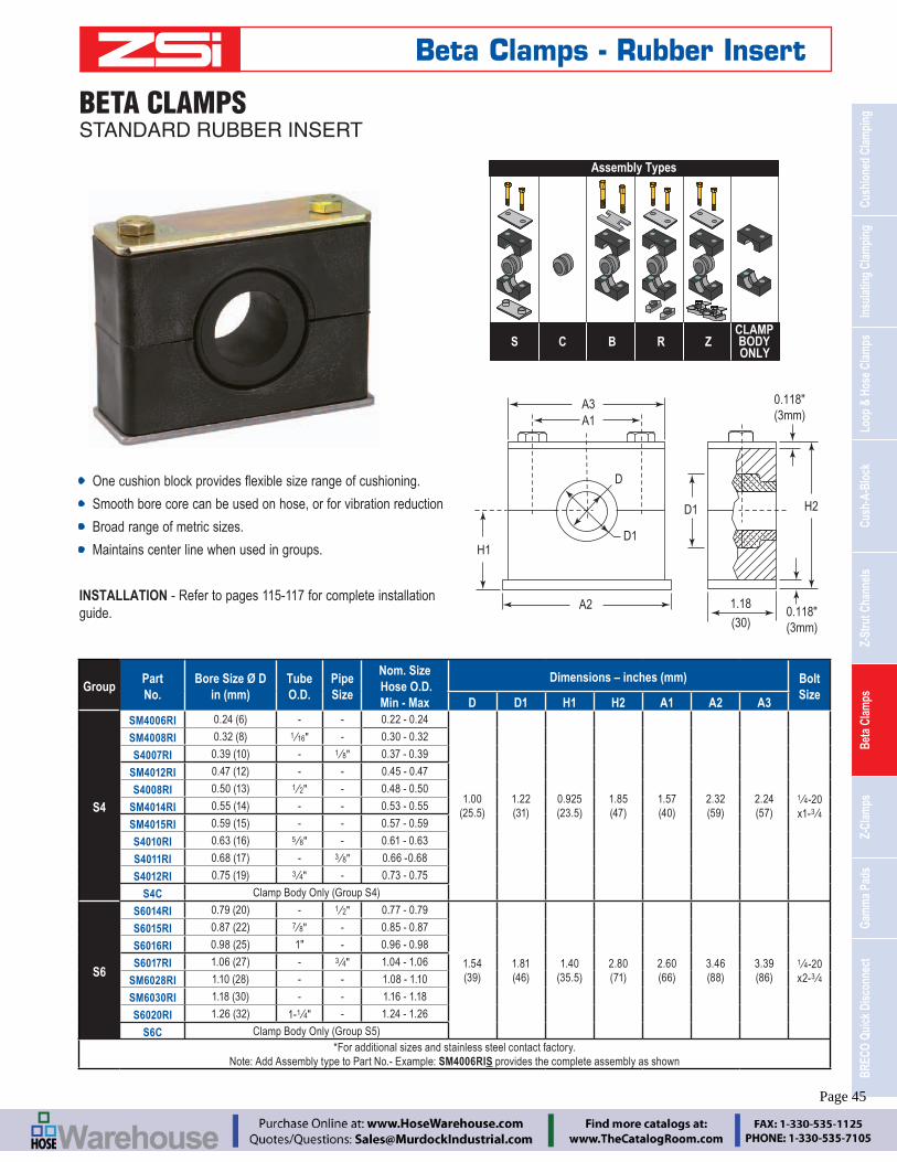
BREC
O Qu
ick
Disc
onne
ctGa
mm
a Pa
dsZ-
Clam
psBe
ta C
lam
psZ-
Stru
t Cha
nnel
sCu
sh-A
-Blo
ckLo
op &
Hos
e Cl
amps
Insu
latin
g Cl
ampi
ngCu
shio
ned
Clam
ping
Engineering Catalog www.zsi-inc.com – 45 –
BETA CLAMPSSTANDARD RUBBER INSERT
Smooth bore core can be used on hose, or for vibration reduction
Broad range of metric sizes.
Maintains center line when used in groups.
INSTALLATION - Refer to pages 115-117 for complete installation guide.
0.118"(3mm)
0.118"(3mm)
1.18
(30)
A1
A2
A3
D
D1
D1
H1
H2
Assembly Types
CLAMPBODYONLY
BS R ZC
Beta Clamps - Rubber Insert
GroupPart No.
Bore Size Ø Din (mm)
TubeO.D.
Pipe Size
Nom. Size Hose O.D.Min - Max
Dimensions – inches (mm) Bolt Size
D D1 H1 H2 A1 A2 A3
S4
SM4006RI - - 0.22 - 0.24
1.00 1.22 0.925 1.85 1.57 2.32 2.24 1 ⁄4-20 x1-3 ⁄4
SM4008RI 1 ⁄16" - 0.30 - 0.32
S4007RI - 1 ⁄8" 0.37 - 0.39
SM4012RI - - 0.45 - 0.47
S4008RI 1 ⁄2" - 0.48 - 0.50
SM4014RI - - 0.53 - 0.55
SM4015RI - - 0.57 - 0.59
S4010RI 5 ⁄8" - 0.61 - 0.63
S4011RI - 3 ⁄8" 0.66 -0.68
S4012RI 3 ⁄4" - 0.73 - 0.75
S4C
S6
S6014RI - 1 ⁄2" 0.77 - 0.79
1.54 1.81 1.40 2.80 2.60 3.46 3.39 1 ⁄4-20 x2-3 ⁄4
S6015RI 7 ⁄8" - 0.85 - 0.87
S6016RI 1" - 0.96 - 0.98
S6017RI - 3 ⁄4" 1.04 - 1.06
SM6028RI - - 1.08 - 1.10
SM6030RI - - 1.16 - 1.18
S6020RI 1-1 ⁄4" - 1.24 - 1.26
S6C*For additional sizes and stainless steel contact factory.
Note: Add Assembly type to Part No.- Example: SM4006RIS provides the complete assembly as shown
Page 45
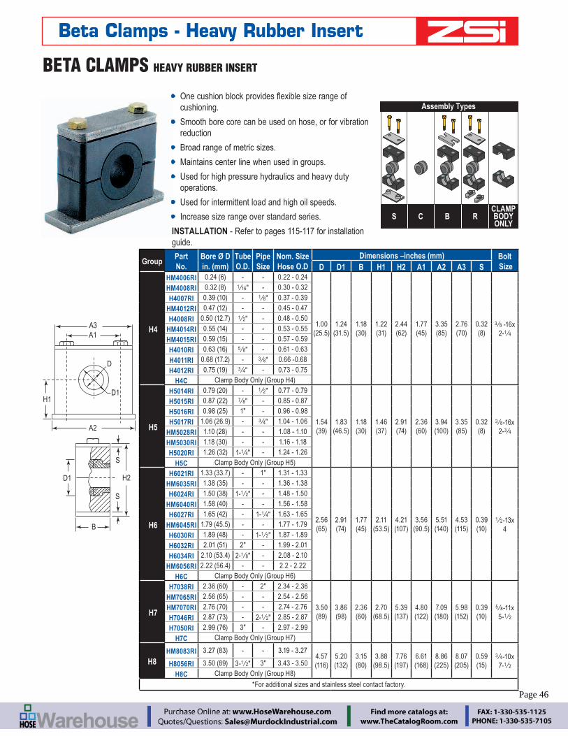
– 46 – www.zsi-inc.com
BETA CLAMPS HEAVY RUBBER INSERT
cushioning.
Smooth bore core can be used on hose, or for vibration reduction
Broad range of metric sizes.
Maintains center line when used in groups.
Used for high pressure hydraulics and heavy duty operations.
Used for intermittent load and high oil speeds.
Increase size range over standard series.
INSTALLATION - Refer to pages 115-117 for installation guide.
A1
H1
H2
B
A3
D1
D1
D
A2
S
S
Assembly Types
CLAMPBODYONLY
S RC B
Beta Clamps - Heavy Rubber Insert
GroupPart No.
Bore Ø D in. (mm)
Tube O.D.
Pipe Size
Nom. Size Hose O.D
Dimensions –inches (mm) Bolt SizeD D1 B H1 H2 A1 A2 A3 S
H4
HM4006RI - - 0.22 - 0.24
1.00 1.24 1.18 1.22 2.44 1.77 3.35 2.76 0.32 3 ⁄8 -16x 2-1 ⁄4
HM4008RI 1 ⁄16" - 0.30 - 0.32
H4007RI - 1 ⁄8" 0.37 - 0.39
HM4012RI - - 0.45 - 0.47
H4008RI 1 ⁄2" - 0.48 - 0.50
HM4014RI - - 0.53 - 0.55
HM4015RI - - 0.57 - 0.59
H4010RI 5 ⁄8" - 0.61 - 0.63
H4011RI - 3 ⁄8" 0.66 -0.68
H4012RI 3 ⁄4" - 0.73 - 0.75
H4C
H5
H5014RI - 1 ⁄2" 0.77 - 0.79
1.54 1.83 1.18 1.46 2.91 2.36 3.94 3.35 0.32 3 ⁄8-16x 2-3 ⁄4
H5015RI 7 ⁄8" - 0.85 - 0.87
H5016RI 1" - 0.96 - 0.98
H5017RI - 3 ⁄4" 1.04 - 1.06
HM5028RI - - 1.08 - 1.10
HM5030RI - - 1.16 - 1.18
H5020RI 1-1 ⁄4" - 1.24 - 1.26
H5C
H6
H6021RI - 1" 1.31 - 1.33
2.56 2.91 1.77 2.11 4.21 3.56 5.51 4.53 0.39 1 ⁄2-13x 4
HM6035RI - - 1.36 - 1.38
H6024RI 1-1 ⁄2" - 1.48 - 1.50
HM6040RI - - 1.56 - 1.58
H6027RI - 1-1 ⁄4" 1.63 - 1.65
HM6045RI - - 1.77 - 1.79
H6030RI - 1-1 ⁄2" 1.87 - 1.89
H6032RI 2" - 1.99 - 2.01
H6034RI 2-1 ⁄8" - 2.08 - 2.10
HM6056RI - - 2.2 - 2.22
H6C
H7
H7038RI - 2" 2.34 - 2.36
3.50 3.86 2.36 2.70 5.39 4.80 7.09 5.98 0.39 5 ⁄8-11x 5-1 ⁄2
HM7065RI - - 2.54 - 2.56
HM7070RI - - 2.74 - 2.76
H7046RI - 2-1 ⁄2" 2.85 - 2.87
H7050RI 3" - 2.97 - 2.99
H7C
H8HM8083RI - - 3.19 - 3.27
4.57 5.20 3.15 3.88 7.76 6.61 8.86 8.07 0.59 3 ⁄4-10x 7-1 ⁄2H8056RI 3-1 ⁄2" 3" 3.43 - 3.50
H8C*For additional sizes and stainless steel contact factory.
Page 46
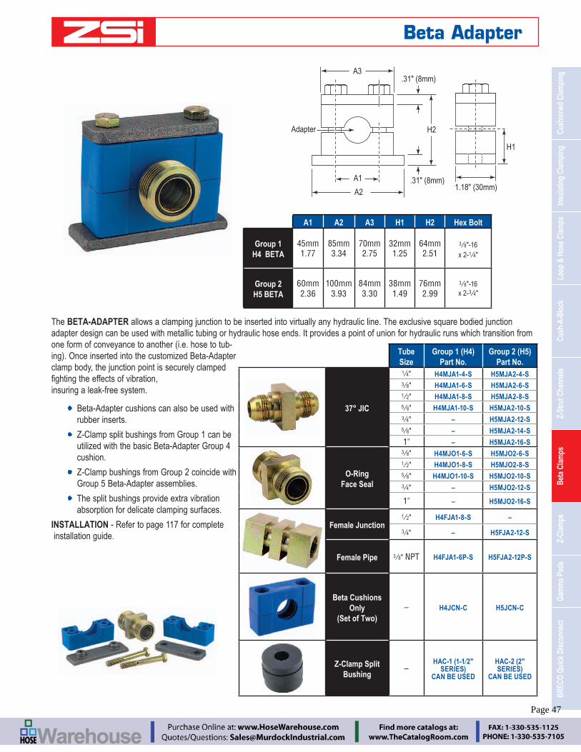
BREC
O Qu
ick
Disc
onne
ctGa
mm
a Pa
dsZ-
Clam
psBe
ta C
lam
psZ-
Stru
t Cha
nnel
sCu
sh-A
-Blo
ckLo
op &
Hos
e Cl
amps
Insu
latin
g Cl
ampi
ngCu
shio
ned
Clam
ping
Engineering Catalog www.zsi-inc.com – 47 –
The BETA-ADAPTER allows a clamping junction to be inserted into virtually any hydraulic line. The exclusive square bodied junction adapter design can be used with metallic tubing or hydraulic hose ends. It provides a point of union for hydraulic runs which transition from one form of conveyance to another (i.e. hose to tub-
clamp body, the junction point is securely clamped
insuring a leak-free system.
Beta-Adapter cushions can also be used with rubber inserts.
Z-Clamp split bushings from Group 1 can be utilized with the basic Beta-Adapter Group 4 cushion.
Z-Clamp bushings from Group 2 coincide with Group 5 Beta-Adapter assemblies.
The split bushings provide extra vibration absorption for delicate clamping surfaces.
INSTALLATION - Refer to page 117 for complete installation guide.
.31" (8mm)
.31" (8mm)
H2
A1
A2
A3
Adapter
1.18" (30mm)
H1
Beta Adapter
A1 A2 A3 H1 H2 Hex Bolt
Group 1H4 BETA
45mm 1.77
85mm 3.34
70mm 2.75
32mm 1.25
64mm 2.51
3 ⁄8"-16 x 2-1 ⁄4"
Group 2H5 BETA
60mm 2.36
100mm 3.93
84mm 3.30
38mm 1.49
76mm 2.99
3 ⁄8"-16 x 2-3 ⁄4"
Tube Size
Group 1 (H4) Part No.
Group 2 (H5) Part No.
37° JIC
1 ⁄4" H4MJA1-4-S H5MJA2-4-S 3 ⁄8" H4MJA1-6-S H5MJA2-6-S 1 ⁄2" H4MJA1-8-S H5MJA2-8-S 5 ⁄8" H4MJA1-10-S H5MJA2-10-S 3 ⁄4" – H5MJA2-12-S 5 ⁄8" – H5MJA2-14-S
1" – H5MJA2-16-S
O-Ring Face Seal
3 ⁄8" H4MJO1-6-S H5MJO2-6-S 1 ⁄2" H4MJO1-8-S H5MJO2-8-S 5 ⁄8" H4MJO1-10-S H5MJO2-10-S 3 ⁄4" – H5MJO2-12-S
1" – H5MJO2-16-S
Female Junction 1 ⁄2" H4FJA1-8-S –
3 ⁄4" – H5FJA2-12-S
Female Pipe 3 ⁄8" NPT H4FJA1-6P-S H5FJA2-12P-S
Beta Cushions Only
(Set of Two) – H4JCN-C H5JCN-C
Z-Clamp Split Bushing
– SERIES) CAN BE USED
HAC-2 (2" SERIES)
CAN BE USED
Page 47

– 48 – www.zsi-inc.com
O-RING FACE SEAL
FEMALE JUNCTION ADAPTER
37° FLARE MALE JUNCTION ADAPTER
The Z-Clamp is designed to maintain a consistent center line dimension for horizontal clamping or vertical stackable clamping applications. Z-Clamp maintains that center line while accommodating the same, or different diameter tubing, hose or pipe. Suited for all types of hydraulic hose, tubing, and pipe clamping applications, the Z-Clamp provides yet another alternative to the broadest cushion clamping product line in the world.
A Z-Clamp consists of an adapter framework which is offered in two versions. One has mounting bolts between each adapter insert and the other has two additional mounting bolts at each end of the frame.
Z-CLAMP UNITS
Standard framework, bolts between each adapter
The Z-Clamp inserts are also used with the Beta Adapter.
Z-CLAMP & BETA ADAPTER OPTIONAL ADAPTERS
RUBBER SPLIT BUSHINGS
Outside hole framework, bolts between each adapter and two additional bolts at each endZ-Clamps can be stacked for even
more line clamping ability.
Z–Clamp - Overview
Page 48

BREC
O Qu
ick
Disc
onne
ctGa
mm
a Pa
dsZ-
Clam
psBe
ta C
lam
psZ-
Stru
t Cha
nnel
sCu
sh-A
-Blo
ckLo
op &
Hos
e Cl
amps
Insu
latin
g Cl
ampi
ngCu
shio
ned
Clam
ping
Engineering Catalog www.zsi-inc.com – 49 –
Z-CLAMP - MULTIPLE LINE CLAMPING SYSTEMSTANDARD CLAMP UNITS
The standard Z-Clamp unit features an anchor bolt between each of the adapter inserts.
The junction adapter provides break points in lines allowing for shorter hose and tubing runs reducing leaks at connection points by securing the adapter against vibration within the Z-Clamp units. These break points may also serve as securely clamped change-over points between hose and tube, and vice versa.
Stackable for space conservation
Maintains consistent center line dimensions between lines both
Mix and match pipe, tube, hose and junction adapters
Suited for all types of hydraulic applications
Available in standard and outside hole
INSTALLATION - Refer to page 117 for complete installation guide.
R
A
B
E
BCDoubleMetalThickness
H
F G (Bolt Holes,Between Holes Only)
Note: Adapters and Hardware are ordered separately. Please see pages 51-53 for selection of these items.
Z–Clamp - Standard
Part No.
# Adapter Holes
# Bolts
A B C E F G H R
HAC-1 Series 1-1⁄2" 14 Gauge
HAC-1-2 2 1 2.938" 1.5" 0.719" 0.75" 1.469" 0.344" 0.550" 0.422"
HAC-1-3 3 2 4.406" 1.5" 0.719" 0.75" 1.469" 0.344" 0.550" 0.422"
HAC-1-4 4 3 5.940" 1.5" 0.719" 0.75" 1.469" 0.344" 0.550" 0.422"
HAC-1-5 5 4 7.140" 1.5" 0.594" 0.75" 1.343" 0.344" 0.550" 0.422"
HAC-1-6 6 5 8.938" 1.5" 0.719" 0.75" 1.469" 0.344" 0.550" 0.422"
HAC-1-7 7 6 10.188" 1.5" 0.594" 0.75" 1.343" 0.344" 0.550" 0.422"
HAC-1-32 32 31 48.00" 1.5" - 0.75" - 0.344" 0.550" 0.422"
HAC-2 Series 2" 14 Gauge
HAC-2-2 2 1 3.875" 2" 0.938" 1" 1.938" 0.344" 0.550" 0.594"
HAC-2-3 3 2 5.641" 2" 0.844" 1" 1.844" 0.344" 0.550" 0.594"
HAC-2-4 4 3 7.891" 2" 0.938" 1" 1.938" 0.344" 0.550" 0.594"
HAC-2-5 5 4 9.672" 2" 0.844" 1" 1.844" 0.344" 0.550" 0.594"
HAC-2-6 6 5 11.672" 2" 0.813" 1" 1.813" 0.344" 0.550" 0.594"
HAC-2-7 7 6 13.625" 2" 0.813" 1" 1.813" 0.344" 0.550" 0.594"
HAC-2-24 24 23 48.00" 2" - 1" - 0.344" 0.550" 0.594"
HAC-3 Series 3" 11 Gauge
HAC-3-2 2 1 6.766" 3" 1.875" 1.5" 3.375" 0.406" 0.750" 1.063"
HAC-3-3 3 2 8.703" 3" 1.406" 1.5" 2.984" 0.406" 0.750" 1.063"
HAC-3-4 4 3 11.703" 3" 1.406" 1.5" 2.797" 0.406" 0.750" 1.063"
HAC-3-5 5 4 14.703" 3" 1.406" 1.5" 2.859" 0.406" 0.750" 1.063"
HAC-3-6 6 5 17.703" 3" 1.406" 1.5" 2.859" 0.406" 0.750" 1.063"
HAC-3-16 16 15 48.00" 3" - 1.5" - 0.406" 0.750" 1.063"
NOTE: Hardware & Adapters not included.
Page 49

– 50 – www.zsi-inc.com
Z-CLAMPOUTSIDE HOLE CLAMP UNITS
Stackable for space conservation
Maintains consistent center line dimensions between lines both
Mix and match pipe, tube, hose and junction adapters
Suited for all types of hydraulic applications
INSTALLATION - Refer to page 117 for complete installation guide.
A
C B
R
B DoubleMetalThickness
H
G (Bolt Holes,Between Holes andat Each End)
B
E
Note: Adapters and Hardware are ordered separately. Please see pages 51-53 for selection of these items.
Z–Clamp - Outside Holes
Part No.
# Adapter Holes
# Bolts
A B C E G H R
HAC-1 Series 1-1⁄2"
HAC 1-1-2 1 2 2.188" 1.5" 0.344" 0.75" 0.344" 0.550" 0.422"
HAC 1-2-3 2 3 3.797" 1.5" 0.391" 0.75" 0.344" 0.550" 0.422"
HAC 1-3-4 3 4 5.297" 1.5" 0.391" 0.75" 0.344" 0.550" 0.422"
HAC 1-4-5 4 5 6.797" 1.5" 0.391" 0.75" 0.344" 0.550" 0.422"
HAC 1-5-6 5 6 8.297" 1.5" 0.391" 0.75" 0.344" 0.550" 0.422"
HAC-2 Series 2"
HAC-2-1-2 1 2 2.656" 2" 0.328" 1" 0.344" 0.550" 0.594"
HAC-2-2-3 2 3 4.766" 2" 0.391" 1" 0.344" 0.550" 0.594"
HAC-2-3-4 3 4 6.797" 2" 0.391" 1" 0.344" 0.550" 0.594"
HAC-2-4-5 4 5 8.297" 2" 0.391" 1" 0.344" 0.550" 0.594"
HAC-3 Series 3"
HAC-3-1-2 1 2 4.000" 3" 0.500" 1.5" 0.406" 0.750" 1.063"
HAC-3-2-3 2 3 6.859" 3" 0.422" 1.5" 0.406" 0.750" 1.063"
HAC-3-3-4 3 4 9.859" 3" 0.422" 1.5" 0.406" 0.750" 1.063"
HAC-3-4-5 4 5 12.859" 3" 0.422" 1.5" 0.406" 0.750" 1.063"Page 50

BREC
O Qu
ick
Disc
onne
ctGa
mm
a Pa
dsZ-
Clam
psBe
ta C
lam
psZ-
Stru
t Cha
nnel
sCu
sh-A
-Blo
ckLo
op &
Hos
e Cl
amps
Insu
latin
g Cl
ampi
ngCu
shio
ned
Clam
ping
Engineering Catalog www.zsi-inc.com – 51 –
A
B
SOCKET HEAD STACKING NUT
THREAD ADAPTER (Install or Stack)
Z-CLAMPHARDWARE
A
B
WELD NUT
A
L
C
B
A
HEX BOLT and HEX NUT
LOCK WASHER
Z–Clamp - Hardware
Part No. HAC Series A B Dia. Thread sizeS-1 1 1.335" 1 ⁄2" 5 ⁄16"-18
S-2 2 1.800" 1 ⁄2" 5 ⁄16"-18
S-3 3 2.780" 11 ⁄16" 3 ⁄8"
Part No. HAC Series A B Dia. Thread sizeT-1 1 & 2 1.38" 0.63" 5 ⁄16"-18
T-3 3 2.00" 0.88" 3 ⁄8"-16
Part No. HAC Series ThreadSize A B C LW-1 / W-2 HAC 1&2 5 ⁄16-18 0.437 0.12 0.875 3 ⁄4
W-3 HAC 3 3 ⁄8-16 0.531 0.151 1.00 1.00
Part No. HAC Series Thread size AHB-1 HAC 1 & 2 5 ⁄16"-18 3 ⁄4"
HB-3 HAC 3 3 ⁄8"-16 1"
Part No. HAC Series sizeHW-1 HAC 1 & 2 5 ⁄16"
HW-3 HAC 3 3 ⁄8"
Page 51

– 52 – www.zsi-inc.com
II
H
C CDD
E
B Ref.
F
G
A
O-RING FACE SEAL
Offered in a wide range of sizes in JIC, NPT, SAE, and ORFS
Zinc plated to prevent corrosion
related leaks
FOR USE with BETA ADAPTERS & Z-CLAMPS
AA .25" .25"
.54
E
D
B
B
37° FLARE MALE JUNCTION ADAPTER
FOR USE with BETA ADAPTERS & Z-CLAMPS
Offered in a wide range of sizes in JIC, NPT, SAE, and
Zinc plated to prevent corrosion
vibration related leaks
Z–Clamp - Adapters
Part No.
Tube Size
Dimensions – inchesA B. C D E F. G I (Thread) H
MJO-1-6 3 ⁄8" 1.00" 1.96" 0.43" 0.28" 0.54" 0.26" 0.84" 11 ⁄16"-16 0.496"
MJO-1-8 1 ⁄2" 1.00" 2.10" 0.50" 0.28" 0.54" 0.38" 0.84" 13 ⁄16"-16 0.621"
MJO-1-10 5 ⁄8" 1.00" 2.30" 0.60" 0.28" 0.54" 0.48" 0.84" 1"-14 0.748"
MJO-2-6 3 ⁄8" 1.50" 2.08" 0.43" 0.34" 0.54" 0.26" 1.20" 11 ⁄16"-16 0.496"
MJO-2-8 1 ⁄2" 1.50" 2.22" 0.50" 0.34" 0.54" 0.38" 1.20" 13 ⁄16"-16 0.621"
MJO-2-10 5 ⁄8" 1.50" 2.42" 0.60" 0.34" 0.54" 0.48" 1.20" 1"-14 0.748"
MJO-2-12 3 ⁄4" 1.50" 2.52" 0.65" 0.34" 0.54" 0.61" 1.20" 1-3 ⁄16"-12 0.873"
MJO-2-16 1" 1.50" 2.58" 0.68" 0.34" 0.54" 0.81" 1.20" 1-7 ⁄16"-12 1.058"
MJO-3-20 1-1 ⁄4" 2.25" 2.98" 0.68" 0.437" 0.75" 1.02" 2.12" 1-11 ⁄16"-12 1.309"
MJO-3-24 1-1 ⁄2" 2.25" 2.98" 0.68" 0.437" 0.75" 1.26" 2.12" 2"-12 1.621"
Part No.
Tube SizeDimensions – Inches E
(Thread)A B D1-1⁄2" Series
MJA-1-4 1 ⁄4" 0.76" 1" 0.84" 7 ⁄16"-20
MJA-1-6 3 ⁄8" 0.76" 1" 0.84" 9 ⁄16"-18
MJA-1-8 1 ⁄2" 0.87" 1" 0.84" 3 ⁄4"-16
MJA-1-10 5 ⁄8" 0.96" 1" 0.84" 7 ⁄8"-14
2" SeriesMJA-2-4 1 ⁄4" 0.76" 1-1 ⁄2" 1.20" 7 ⁄16"-20
MJA-2-6 3 ⁄8" 0.76" 1-1 ⁄2" 1.20" 9 ⁄16"-18
MJA-2-8 1 ⁄2" 0.87" 1-1 ⁄2" 1.20" 3 ⁄4"-16
MJA-2-10 5 ⁄8" 0.96" 1-1 ⁄2" 1.20" 7 ⁄8"-14
MJA-2-12 3 ⁄4" 1.07" 1-1 ⁄2" 1.20" 1-1 ⁄16"-12
MJA-2-14 7 ⁄8" 1.10" 1-1 ⁄2" 1.20" 1-3 ⁄16"-12
MJA-2-16 1" 1.10" 1-1 ⁄2" 1.20" 1-5 ⁄16"-12
Page 52

BREC
O Qu
ick
Disc
onne
ctGa
mm
a Pa
dsZ-
Clam
psBe
ta C
lam
psZ-
Stru
t Cha
nnel
sCu
sh-A
-Blo
ckLo
op &
Hos
e Cl
amps
Insu
latin
g Cl
ampi
ngCu
shio
ned
Clam
ping
Engineering Catalog www.zsi-inc.com – 53 –
SPLIT RUBBER BUSHINGS
C
D
E
A
B
ANTI-VIBRATION SPLIT RUBBER BUSHING
Unique “grip” design secures cushion in place
High quality EPDM rubber provides superior vibration damping with excellent oil resistance.
FEMALE JUNCTION ADAPTER
G GB Ref.
F D DE E
C
A
FOR USE with BETA ADAPTERS & Z-CLAMPS
Offered in a wide range of sizes in JIC, NPT, SAE, and ORFS
Zinc plated to prevent corrosion
related leaks
FOR USE with BETA ADAPTERS & Z-CLAMPS
Z–Clamp - Adapters
Part No. Tube Size Pipe Size A B C D E
HAC-1 1-1⁄2" SeriesG-1-4 1 ⁄4" – 0.235" 0.975" 0.875" 0.50" 1.312"
G-1-6 3 ⁄8" – 0.360" 0.975" 0.875" 0.50" 1.312"
G-1-8 1 ⁄2" – 0.485" 0.975" 0.875" 0.50" 1.312"
G-1-10 5 ⁄8" – 0.610" 0.975" 0.875" 0.50" 1.312"
G-1-12 3 ⁄4" – 0.735" 0.975" 0.875" 0.50" 1.312"
HAC-2 2" Series
G-2-4 1 ⁄4" – 0.235" 1.350" 1.250" 0.50" 1.312"
G-2-6 3 ⁄8" – 0.360" 1.350" 1.250" 0.50" 1.312"
G-2-8 1 ⁄2" – 0.485" 1.350" 1.250" 0.50" 1.312"
G-2-4P – 1 ⁄4" 0.525" 1.350" 1.250" 0.50" 1.312"
G-2-10 5 ⁄8" – 0.610" 1.350" 1.250" 0.50" 1.312"
G-2-6P 3 ⁄8" 0.660" 1.350" 1.250" 0.50" 1.312"
G-2-12 3 ⁄4" 0.735" 1.350" 1.250" 0.50" 1.312"
G-2-8P – 1 ⁄2" 0.825" 1.350" 1.250" 0.50" 1.312"
G-2-14 7 ⁄8" – 0.860" 1.350" 1.250" 0.50" 1.312"
G-2-16 1" – 0.985" 1.350" 1.250" 0.50" 1.312"
G-2-12P 3 ⁄4" 1.035" 1.350" 1.250" 0.50" 1.312"
HAC-3 3" Series
G-3-4 1 ⁄4" – 0.234" 2.287" 2.187" 0.750" 1.750"
G-3-6 3 ⁄8" – 0.360" 2.287" 2.187" 0.750" 1.750"
G-3-8 1 ⁄2" – 0.485" 2.287" 2.187" 1.750"
G-3-4P – 1 ⁄4" 0.525" 2.287" 2.187" 0.750" 1.750"
G-3-10 5 ⁄8" – 0.610" 2.287" 2.187" 0.750" 1.750"
G-3-6P – 3 ⁄8" 0.660" 2.287" 2.187" 0.750" 1.750"
G-3-12 3 ⁄4" – 0.735" 2.287" 2.187" 0.750" 1.750"
G-3-8P – 1 ⁄2" 0.825" 2.287" 2.187" 0.750" 1.750"
G-3-14 7 ⁄8" – 0.860" 2.287" 2.187" 0.750" 1.750"
G-3-16 1" – 0.985" 2.287" 2.187" 0.750" 1.750"
G-3-12P – 3 ⁄4" 1.035" 2.287" 2.187" 0.750" 1.750"
G-3-20 1-1 ⁄4" 1.235" 2.287" 2.187" 0.750" 1.750"
G-3-16P – 1" 1.300" 2.287" 2.187" 0.750" 1.750"
G-3-24 1-1 ⁄2" – 1.485" 2.287" 2.187" 0.750" 1.750"
G-3-20P – 1-1 ⁄4" 1.645" 2.287" 2.187" 0.750" 1.750"
G-3-24P – 1-1 ⁄2" 1.885" 2.287" 2.187" 0.750" 1.750"
G-3-32 2" – 1.985" 2.287" 2.187" 0.750" 1.750"
Part No.
Dimensions – Inches G (Thread)A B C D E. F
FJA-1-6-P 1" 2-13 ⁄16" 0.84" 0.84" 0.30" 0.54" 3 ⁄8" N.P.T.
FJA-2-12-P 1-1 ⁄2" 3-1 ⁄8" 1.20" 0.97" 0.32" 0.54" 3 ⁄4" N.P.T.
FJA-3-20-P 2-1 ⁄4" 2-5 ⁄8" 2.12" 0.49" 0.45" 0.74" 1-1 ⁄4" N.P.T.
FJA-1-8 1" 2-13 ⁄16" 0.84" 0.84" 0.30" 0.54" 3 ⁄4"-16 SAE
FJA-2-12 1-1 ⁄2" 3-1 ⁄8" 1.20" 0.97" 0.32" 0.54" 1-1 ⁄16"-12 SAE
FJA-3-20 2-1 ⁄4" 2-5 ⁄8" 2.12" 0.49" 0.45" 0.74" 1-5 ⁄8"-12 SAE
Page 53

– 54 – www.zsi-inc.com
surge, galvanic corrosion and unwanted noise are a major concern. Imprope p op-erly cushioned equipment, pipe, tube, or hose invites failure and potentialproblems. New developments in cushioned clamping and vibration isolation products from ZSi provide the proper solutions to combat these eeffects.
ZSi's products have earned a well-deserved reputation for unparaalleled quality and effectiveness. As industry develops new needs, ZSi can andd will respond with superior quality products and innovative solutions.
E.V.A.
Rubber/Cork
Iso-Cube
Competition
ANTI-VIBRATION PAD PERFORMANCE
Nor
mal
ized
Vib
ration
Red
uction
(VR
)
Vibration Frequency (VF)Test Table Speed (TS)
GAMMA PADS
GAMMA Anti-Vibration Pads
Page 54

BREC
O Qu
ick
Disc
onne
ctGa
mm
a Pa
dsZ-
Clam
psBe
ta C
lam
psZ-
Stru
t Cha
nnel
sCu
sh-A
-Blo
ckLo
op &
Hos
e Cl
amps
Insu
latin
g Cl
ampi
ngCu
shio
ned
Clam
ping
Engineering Catalog www.zsi-inc.com – 55 –
GAMMA SHIELD - RUBBER MAT GAMMA STANDARD PAD
ISO - CUBE - SOLID RUBBER TOUGH GAMMA EXTREME PAD
The BEST latest generation in vibration dampening technology. In the most severe vibration extremes, testing shows the E.V.A. pad outperforms cork and rubber by greater than 3:1 and outperforms our competitor's
comes from the special composite foam center which is structurally more sound than cork. E.V.A. is not affected by oils or
chemicals that can break down cork and is much more effective at vibration dampening than
solid rubber. Designed to withstand 50 psi. Choose E.V.A. to get the best
The Industry Standard Highest quality elastomeric oil resistant padding. Designed to withstand 50 psi. The rubber pads are corrugated on both sides and laminated to the cork center.
Natural rubber pads designed to reduce vibration and noise ema-nating from refrigeration or AC equipment. Circular design offers a suction cup effect eliminating the need to bolt the pads down. A standard 18" pad divides into eighty-one 2" segments which may be cut or torn into smaller pads. The 50 durometer pads will withstand a load of 180 psi with great resiliency.
Shields equipment from vibration and movement when lesser amounts of vibration absorption is needed.
GAMMA Anti-Vibration Pads
Part No. DescriptionAR-2 2" x 2" x 3 ⁄8" All Rubber AV Pad
AR-3 3" x 3" x 3 ⁄8" All Rubber AV Pad
AR-4 4" x 4" x 3 ⁄8" All Rubber AV Pad
AR-6 6" x 6" x 3 ⁄8" All Rubber AV Pad
AR-18 18" x 18" x 3 ⁄8" All Rubber AV Pad
Part No. DescriptionAC-2 2" x 2" x 7 ⁄8" Cork / Rubber AV Pad
AC-3 3" x 3" x 7 ⁄8" Cork / Rubber AV Pad
AC-4 4" x 4" x 7 ⁄8" Cork / Rubber AV Pad
AC-6 6" x 6" x 7 ⁄8" Cork / Rubber AV Pad
AC-18 18" x 18" x 7 ⁄8" Cork / Rubber AV Pad
Part No. DescriptionAS-2 2" x 2" x 3 ⁄4" Iso-Cube
AS-18 18" x 18" x 3 ⁄4" Iso-Cube
Part No. DescriptionAV-2 2" x 2" x 7 ⁄8" EVA Pad
AV-3 3" x 3" x 7 ⁄8" EVA Pad
AV-4 4" x 4" x 7 ⁄8" EVA Pad
AV-6 6" x 6" x 7 ⁄8" EVA Pad
AV-18 18" x 18" x 7 ⁄8" EVA Pad
Page 55

– 56 – www.zsi-inc.com
B PAGE 58-59
C, D PAGE 60-61
SV SAFETY PAGE 62-64
SVPC PLASTIC PAGE 62-64
INTERCHANGE PLUGS PAGE 65
Industrial Interchange
J SOCKETS / PLUGS PAGE 66
Tru-Flate
L SOCKETS / PLUGS PAGE 67
Lincoln
O SOCKETS / PLUGS PAGE 68
6600 SOCKETS / PLUGS PAGE 76
ISO "A"
6100 SOCKETS / PLUGS PAGE 74
Wing Nut
DS SOCKETS / PLUGS PAGE 71-72
ISO "B"
W SOCKETS / PLUGS PAGE 77
Enerpac
4000 SOCKETS / PLUGS PAGE 73
Pioneer
H SOCKETS / PLUGS PAGE 79-80
Snap-Tite
INJECTION MOLD SOCKET / PLUGS PAGE 81-82
Mold Mate
FF SOCKETS / PLUGS PAGE 75
Flat Face
ST SOCKETS / PLUGS PAGE 78
Straight Thru
GARDEN HOSE SOCKETS / PLUGS PAGE 83
TL SOCKETS / PLUGS PAGE 70
DW,U PAGE 69
Universal Coupler
HOSE BARB - PAGE 84
STANDARD PUSH LOCK
IN LINE LUBRICATOR PAGE 83
PNEUMATIC SYSTEMS
MISCELLANEOUS
HYDRAULIC SYSTEMS
PIPE FITTINGS
BRASS PAGE 85-86
STEEL PAGE 87
REUSABLE FITTINGS PAGE 85
BLOW GUNS & TIPS PAGE 89-90
DRAIN COCKS PAGE 88
SWIVEL FITTINGS PAGE 88
HOSE MANIFOLDS PAGE 91
AIR HOSES
RECOIL PAGE 92
Table of Contents
Page 56

BREC
O Qu
ick
Disc
onne
ctGa
mm
a Pa
dsZ-
Clam
psBe
ta C
lam
psZ-
Stru
t Cha
nnel
sCu
sh-A
-Blo
ckLo
op &
Hos
e Cl
amps
Insu
latin
g Cl
ampi
ngCu
shio
ned
Clam
ping
Engineering Catalog www.zsi-inc.com – 57 –
How to Select: Proper coupler selection is important because of the variety of media for which they are used. All couplers consist of two basic components – a socket and a plug. The type of coupler varies by the valving arrangements in these two components.
Four basic factors should be considered to assure proper selection:
One Way Shut-Off Two Way Shut-Off Straight-Thru
In a "One Way Shut-Off," only the socket has valving to shut off the flow when disconnected; it is, therefore, installed on the pressure side of the line. The plug has no valving and exhausts the downstream line at disconnect.
The "Two Way Shut-Off" provides valving in both the socket and the plug, thereby shutting off flow at both of the disconnected ends. Originally developed for hydraulic lines, they are suitable for many other media because of the variety of metals and seal compounds offered.
"Straight-Thru" couplers, as the name implies, do not have valving in either the socket or the plug. Therefore, both ends of the line are exhausted at disconnect.
Manual Automatic Safety Coupler
Manual sockets require manual retraction of the sleeve to both connect and disconnect the plug. The "BL Series" is an optional feature available on manual sockets. After connection, the sleeve is rotated locking the coupler against accidental disconnect.
Automatic sockets accept the plug by simple insertion into the socket and do not require retraction of the sleeve to connect. The "SL Series" is an optional feature on automatic sockets to prevent accidental disconnect. It is functionally the same as the "BL Series" on manual sockets.
Safety sockets are a variation of automatic operation. The socket accepts the plug by insertion. The sleeve is moved straight forward to lock and turn on the air. The sleeve is moved back by rotating first to the left and then to the right. This shuts off the supply line, exhausts the downstream line, and then releases the plug.
Type – Operation – Flow – Media
Operation: Operation refers to the action required to connect and disconnect a coupler. Operation is a function of sockets only and does not vary for plugs.
Flow:
Media:
Straight-Thru couplers are suitable where there is no pressure in the line at connect or disconnect and loss of media at disconnect does not matter.
Quick Detachable Couplers
Page 57

– 58 – www.zsi-inc.com
Sleeve-Lock Option (shown on right)
Sleeve-Lock feature locks manual socket against accidental disconnect. To connect, align ball with slot. After connection, rotate sleeve to lock. To disconnect, realign ball with slot and retract sleeve. Sizes available with sleeve lock are shown in the tables on following pages.
BRECO "B" Series couplers are designed for rigid mounting that allows a simple push-to-connect operation, constructed of a solid brass body and a steel valve. The "B" Series are mechanically interchangeable with the "C" , "SV", "SVPC" & "D" Series, and similar industrial interchange couplings made by other manufacturers and accept plugs that conform to MIL-C4109-F. Plugs used with the "B" Series are the Industrial Interchange plugs that are found on page 65 of this catalog.
BODY SIZE
14" 3
8" 12" 3
4"300
Locking Device 3 pawls 4 pawls 5 pawls 6 pawlsVacuum Data
Not Recommended -- Connected 27.4 inches Hg
g )
2 3 4 5 6 7 8 910
10
20
20
40
30
60 50
80 90 100
200
150
3 "
3 "
1 "
1 "
Inlet Pressure 100 PSI 80 PSI
70
10
20
40
30
60 50
80 90
100
200
150
70
Flow
In S
CFM
Pressure Drop in PSI
Series “B” (1 ", 3 ", 1 ", 3 ")
Performance:
Material: Brass body and sleeve
Seal: Buna-N
Working Pressure: 300 PSIG; vacuum to 26"Hg
Connection Sizes: 18" to 1" NPT
14" to 1" Hose Barb
14" to 1
2" Push-on Hose Barb
Interchangeability: Complies with A-A-59439, ANSI/NFPA T3.20.14-1990 & IS0 6150-B
"B" Series Sockets
Page 58

Mis
cella
neou
sHy
drau
lic S
yste
ms
Pneu
mat
ic S
yste
ms
Hose
, Saf
ety
Air L
ine
Prod
ucts
Blow
Gun
sPi
pe F
ittin
gsGa
rden
, Lub
ricat
orM
old
ST. H
6600
, W61
00, F
F40
00TL
, DS
O, D
W, U
J,L
SV, S
VPC,
Int P
lugs
C, D
B
Engineering Catalog www.zsi-inc.com – 59 –
MA
LE T
HR
EAD
SIZE AUTOMATICSLEEVE LOCK
THD SIZE NPT
14"
B-2BM1-B B-2BM1-B-SL 18-27
B-2BM2-B B-2BM2-B-SL 14-18
B-2BM3-B B-2BM3-B-SL 38-18
38"
B-3BM2-B B-3BM2-B-SL 14-18
B-3BM3-B B-3BM3-B-SL 38-18
B-3BM4-B B-3BM4-B-SL 12-14
12"
B-4BM2-B B-4BM2-B-SL 14-18
B-4BM3-B B-4BM3-B-SL 38-18
B-4BM4-B B-4BM4-B-SL 12-14
B-4BM6-B B-4BM6-B-SL 34-14
34"
B-6BM4-B B-6BM4-B-SL 12-14
B-6BM6-B B-6BM6-B-SL 34-14
B-6BM8-B B-6BM8-B-SL 1-1112
FEM
ALE
TH
REA
D
SIZE AUTOMATICSLEEVE LOCK
THD SIZE NPT
14"
B-2BF1-B B-2BF1-B-SL 18-27
B-2BF2-B B-2BF2-B-SL 14-18
B-2BF3-B B-2BF3-B-SL 38-18
38"
B-3BF2-B B-3BF2-B-SL 14-18
B-3BF3-B B-3BF3-B-SL 38-18
B-3BF4-B B-3BF4-B-SL 12-14
12"
B-4BF2-B B-4BF2-B-SL 14-18
B-4BF3-B B-4BF3-B-SL 38-18
B-4BF4-B B-4BF4-B-SL 12-14
B-4BF6-B B-4BF6-B-SL 34-14
34"
B-6BF4-B B-6BF4-B-SL 12-14
B-6BF6-B B-6BF6-B-SL 34-14
B-6BF8-B B-6BF8-B-SL 1-1112
PUSH
-LO
CK B
AR
B
SIZEPART NO. HOSE
I.D.AUTOMATIC SLEEVE LOCK
14"
B-2BPS2-B B-2BPS2-B-SL 14"
B-2BPS3-B B-2BPS3-B-SL 38"
38"
B-3BPS3-B B-3BPS3-B-SL 38"
B-3BPS4-B B-3BPS4-B-SL 12"
12" B-4BPS4-B B-4BPS4-B-SL 1
2"
REU
SEA
BLE
HO
SE F
ITTI
NG
S SIZEPART NO. HOSE
BRASS SLEEVE LOCK I.D. O.D.
14"
B-2BE2-B -
14"
12"
B-2BG2-B - 916"
B-2BH2-B B-2BH2-B-SL 58"
38"
B-3BH3-B B-3BH3-B-SL3
8"
58"
B-3BK3-B B-3BK3-B-SL 1116"
STA
NDA
RD H
OSE
BA
RB
SIZE AUTOMATICSLEEVE LOCK
HOSE I.D.
14"
B-2BS2-B B-2BS2-B-SL 14"
B-2BS5-B B-2BS5-B-SL 516"
B-2BS3-B B-2BS3-B-SL 38"
38"
B-3BS2-B B-3BS2-B-SL 14"
B-3BS5-B B-3BS5-B-SL 516"
B-3BS3-B B-3BS3-B-SL 38"
B-3BS4-B B-3BS4-B-SL 12"
12"
B-4BS2-B B-4BS2-B-SL 14"
B-4BS3-B B-4BS3-B-SL 38"
B-4BS4-B B-4BS4-B-SL 12"
B-4BS6-B B-4BS6-B-SL 34"
34"
B-6BS4-B B-6BS4-B-SL 12"
B-6BS6-B B-6BS6-B-SL 34"
B-6BS8-B B-6BS8-B-SL 1
"B" Series Sockets
Page 59

– 60 – www.zsi-inc.com
FEM
ALE
PIP
E TH
REA
D
BODY SIZE
THD OR HOSE SIZE
"C" SERIESBODY SIZE
THD OR HOSE SIZE
"D" SERIES
BRASS W/ BRASS SLEEVE
STEEL (-S) STAINLESS -(SS)
BRASS W/ STEEL SLEEVE
BRASS W/STEEL SLEEVE SLEEVE LOCK
14"
18–27 B-2CF1-B -
14"
18–27 D320 D320BL
14–18 B-2CF2-B B-2CF2-SS 1
4–18 D340 D340BL3
8–18 B-2CF3-B - 38–18 D360 D360BL
38"
14–18 - B-3CF2-S
38"
14–18 D440 D440BL
38–18 B-3CF3-B B-3CF3-S 3
8–18 D460 D460BL1
2–14 - B-3CF4-S 12–14 D480 D480BL
12"
14–18 - -
12"
14–18 D540 D540BL
38–18 - B-4CF3-S 3
8–18 D560 D560BL1
2–14 B-4CF4-B B-4CF4-S 12–14 D580 D580BL
34–14 - B-4CF6-S 3
4–14 D5120 D5120BL
Features:
1.
2. Precision molded seals form a "bubble tight" seal for reliable
are standard. Ethelyne Propelyne, Viton and Neoprene seals are available as options with the "D" series.
3. Proven ball locking mechanism with large numbers of hardened steel or stainless steel locking balls evenly distribute the load to resist wear and provide positive connections and allows a swiveling action to reduce hose torque.
4. Integral sleeve guard protects the sleeve and resists accidental disconnects for the "C" series.
5. Knurling and/or grooves on the sleeve provide a gripping surface for ease of operation.
6. Wide range of body sizes, materials, options and end
Operation:
Sleeve type couplings are widely used to connect air and low pres-
locking mechanism consisting of captive steel balls that engage the locking groove on the mating plug. The sliding spring loaded sleeve on the socket must be manually retracted in order to connect or dis-connect the plug.
Performance:
"C" & "D" Series (14", 3
8", 12")
20
10
40
30
60 50
80 100
150
70
20
10
40
30
60 50
80 100
150
70
2 3 4 5 6 7 8 9 10 20
Inlet Pressure 100 PSI 80 PSI
1 "
3 "
1 "
Flow
In S
CFM
Pressure Drop in PSI
"D" Series Options:
Sleeve-Lock feature locks manual socket against accidental disconnect. Sizes available with sleeve-lock are shown in tables on following page.
Material: Brass body and socket end, zinc-plated steel sleeve
Working Pressure: 300 PSIG; vacuum to 26"Hg
Interchangeability: Complies with ANSI/NFPA T3.20.14-1990 & IS0 6150-B
BODY SIZE1
4" 38" 1
2"300 300 300
Locking Device Steel Balls
Not Recommended -- Connected 27.4 27.4 27.4
37 70 150
62
1 3
7
45
"C", "D" Series Sockets
Page 60

Mis
cella
neou
sHy
drau
lic S
yste
ms
Pneu
mat
ic S
yste
ms
Hose
, Saf
ety
Air L
ine
Prod
ucts
Blow
Gun
sPi
pe F
ittin
gsGa
rden
, Lub
ricat
orM
old
ST. H
6600
, W61
00, F
F40
00TL
, DS
O, D
W, U
J,L
SV, S
VPC,
Int P
lugs
C, D
B
Engineering Catalog www.zsi-inc.com – 61 –
"C", "D" Series SocketsNotes: Plugs for use with "C" & "D" Series sockets are shown on page 65.
REU
SEA
BLE
HO
SE F
ITTI
NG
S
BODY SIZE
THREAD SIZE OR HOSE SIZE
BRASS W/BRASS SLEEVE
14" 1
2" B-2CE2-B
14" 9
16" B-2CG2-B
14" 5
8" B-2CH2-B
38" 5
8" B-2CH3-B
38" 11
16" B-2CK3-B
PUSH
-LO
CK B
AR
B BODY SIZE
THD OR HOSE SIZE
"C" SERIESBODY SIZE
THD OR HOSE SIZE
"D" SERIES
BRASS W/ BRASS SLEEVE
STEEL (-S) STAINLESS -(SS)
BRASS W/ STEEL SLEEVE
BRASS W/STEEL SLEEVE SLEEVE LOCK
14"
14" B-2CPS2-B - 1
4"1
4" D344 D344BL3
8" B-2CPS3-B - 38" D364 D364BL
38" 3
8" - B-3CPS3-S 38"
38" D464 D464BL
12"
38" - B-4CPS3-S 1
2" D484 D484BL1
2" - B-4CPS4-S 12" 1
2" D584 D584BL
STA
NDA
RD H
OSE
BA
RB
BODY SIZE
THD OR HOSE SIZE
"C" SERIESBODY SIZE
THD OR HOSE SIZE
"D" SERIES
BRASS W/ BRASS SLEEVE
STEEL (-S) STAINLESS -(SS)
BRASS W/ STEEL SLEEVE
BRASS W/STEEL SLEEVE SLEEVE LOCK
14"
14" B-2CS2-B -
14"
14" D342 D342BL
516" B-2CS25-B - 5
16" D352 D352BL3
8" B-2CS3-B - 38" D362 D362BL
38"
14" - -
38"
14" D442 D442BL
516" - - 5
16" D452 D452BL3
8" - B-3CS3-S 38" D462 D462BL
12" - B-3CS4-S 1
2" D482 D482BL
12"
14" - -
12"
14" D542 D542BL
38" - B-4CS3-S 3
8" D562 D562BL1
2" - B-4CS4-S 12" D582 D582BL
34" - B-4CS6-S 3
4" D5122 D5122BL
MA
LE T
HR
EAD
BODY SIZE
THD OR HOSE SIZE
"C" SERIESBODY SIZE
THD OR HOSE SIZE
"D" SERIES
BRASS W/ BRASS SLEEVE
STEEL (-S) STAINLESS -(SS)
BRASS W/ STEEL SLEEVE
BRASS W/STEEL SLEEVE SLEEVE LOCK
14"
18–27 B-2CM1-B -
14"
18–27 D321 D321BL
14–18 B-2CM2-B B-2CM2-SS 1
4–18 D341 D341BL3
8–18 B-2CM3-B - 38–18 D361 D361BL
38"
14–18 - B-3CM2-S
38"
14–18 D441 D441BL
38–18 B-3CM3-B B-3CM3-S 3
8–18 D461 D461BL1
2–14 - B-3CM4-S 12–14 D481 D481BL
12"
14–18 - -
12"
14–18 D541 D541BL
38–18 - B-4CM3-S 3
8–18 D561 D561BL1
2–14 B-4CM4-B B-4CM4-S 12–14 D581 D581BL
34–14 - B-4CM6-S 3
4–14 D5121 D5121BL
Page 61
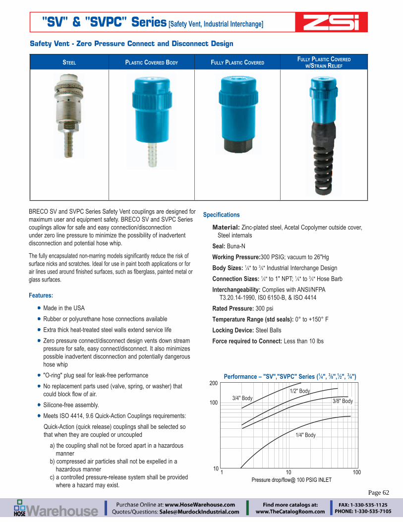
– 62 – www.zsi-inc.com
"SV" & "SVPC" Series [Safety Vent, Industrial Interchange]
BRECO SV and SVPC Series Safety Vent couplings are designed for maximum user and equipment safety. BRECO SV and SVPC Series couplings allow for safe and easy connection/disconnection under zero line pressure to minimize the possibility of inadvertent disconnection and potential hose whip.
surface nicks and scratches. Ideal for use in paint booth applications or for
glass surfaces.
Features:
Made in the USA
Rubber or polyurethane hose connections available
Extra thick heat-treated steel walls extend service life
Zero pressure connect/disconnect design vents down stream pressure for safe, easy connect/disconnect. It also minimizes possible inadvertent disconnection and potentially dangerous hose whip
"O-ring" plug seal for leak-free performance
Silicone-free assembly.
Meets ISO 4414, 9.6 Quick-Action Couplings requirements:
that when they are coupled or uncoupled
manner hazardous manner
where a hazard may exist.
Material: Zinc-plated steel, Acetal Copolymer outside cover, Steel internals
Seal: Buna-N
Working Pressure:300 PSIG; vacuum to 26"Hg
Body Sizes: 14" to 3
4" Industrial Interchange Design
Connection Sizes: 14" to 1" NPT; 1
4" to 34" Hose Barb
Interchangeability: Complies with ANSI/NFPA T3.20.14-1990, IS0 6150-B, & ISO 4414
Rated Pressure: 300 psi
Temperature Range (std seals):
Locking Device: Steel Balls
Force required to Connect: Less than 10 lbs
Safety Vent - Zero Pressure Connect and Disconnect Design
100
100
200
10
1/2" Body
101
Pressure drop/flow@ 100 PSIG INLET
3/4" Body
1/4" Body
3/8" Body
Performance – "SV","SVPC" Series (14", 3
8",12", 3
4")
STEEL PLASTIC COVERED BODY FULLY PLASTIC COVEREDFULLY PLASTIC COVERED
W/STRAIN RELIEF
Page 62

Mis
cella
neou
sHy
drau
lic S
yste
ms
Pneu
mat
ic S
yste
ms
Hose
, Saf
ety
Air L
ine
Prod
ucts
Blow
Gun
sPi
pe F
ittin
gsGa
rden
, Lub
ricat
orM
old
ST. H
6600
, W61
00, F
F40
00TL
, DS
O, D
W, U
J,L
SV, S
VPC,
Int P
lugs
C, D
B
Engineering Catalog www.zsi-inc.com – 63 –
Depressurized& UnlockedPlug can now be inserted or, removed
Pressurized& Locked
Vents Allow Pressure tobe Released
1
1
2 3
4
5
5
Socket EndBody
Sleeve
Vent Holes forPressure Release
Plug isInserted Into
the SV Coupler
Operation:
SV and SVPC Series Safety Vent couplers are nearly effortless to connect and great for hose use. They are also especially useful for single-hand operation when they are mounted to hard lines such as an overhead air drop.
Once inserted into the SV or SVPC socket, the plug is lightly gripped and will stay in place allowing the operator to use the same hand to slide the sleeve straight forward to the "on" position.
SV or SVPC Series sockets can also be used as a 3-way valve
without disengaging the plug. By turning and sliding the sleeve to the "exhaust" position, downstream air pressure is relieved but the plug remains locked in place. Turning and sliding the sleeve in the
BRECO SV or SVPC Series couplers are the ultimate solution to accidental disconnect hose whip dangers.
REMOVE PLUG – OUTPUT PRESSURE IS AUTOMATICALLY ZERO
REMOVE PRESSURE FROM OUTPUT -- ACTS AS A SHUT-OFF VALVE --
"SV" & "SVPC" Series [Safety Vent, Industrial Interchange]
Twist grip up & slide backto release pressure
InputOutput
Output Pressure is Released
Vent Holes release pressure to eliminate “Hose Whip”, and
make the coupler “Self Cleaning”
InputOutput
When Output=0 pressure turn slightly down &forward to allow release. Coupler automaticallyprevents this action if pressure not yet released
InputOutput
Since output pressure is zero, and coupleris in release position, Plug can be removed
InputOutput
SYSTEM UNDER PRESSURE (BOTH SOURCE AND OUTPUT)
INSERT PLUG – OUTPUT IS ZERO PRESSURE
PLUG IS LOCKED IN PLACE, NOW RESTORE OUTPUT PRESSURE
Make sure sleeve is fully extended to allow pressure on the output plug
InputOutput
Make sure sleeve is fully retracted toallow insertion of the plug.
Output pressure is zero at this point.
InputOutput
sleeve
InputOutput
Page 63

– 64 – www.zsi-inc.com
HO
SE B
AR
B (R
EQU
IRES
HO
SE C
LAM
P)
BODY SIZE PART NO. STEEL SIZE PART NO. BODY PLASTIC COVERED1
4" 14" SV3603 1
4" SVPC36031
4" 38" SV3703 3
8" SVPC37031
2" 38" SV5705 3
8" SVPC57051
2" 12" SV5805 1
2" SVPC58051
2" 34" SV5905 3
4" SVPC59053
8" 14" SV4604 1
4" SVPC46043
8" 38" SV4804 3
8" SVPC48043
8" 12" SV4904 1
2" SVPC49043
4" 34" SV6906 3
4" SVPC6906
BODY SIZE PART NO. FULLY PLASTIC COVERED, W/STRAIN RELIEF
SIZE PART NO FULLY PLASTIC COVERED, W/O STRAIN RELIEF
38" 3
8" SVPCA66.R
38" Body
12" Body
38" SVPCA62.R
38" Body
12" Body
38" 3
8" SVPCA66.P 38" SVPCA62.P
38" 7
16" SVPCA76.P 716" SVPCA72.P
38" 1
2" SVPCA86 12" SVPCA82
12" 7
16" SVPC276.P 716" SVPC272.P
12" 3
8" SVPC266.R 38" SVPC262.R
12" 3
8" SVPC266.P 38" SVPC262.P
12" 1
2" – 12" SVPC282
FEM
ALE
PIP
E TH
REA
DBODY SIZE PART NO. / STEEL SIZE PART NO. / BODY PLASTIC COVERED SIZE PART NO. / FULLY PLASTIC COVERED
14" 1
4" SV3003 14" SVPC3003 1
4" –
38" Body
12" Body
14" 3
8" SV3203 38" SVPC3203 3
8" –3
8" 14" SV4004 1
4" SVPC4004 14" –
38" 3
8" SV4204 38" SVPC4204 3
8" SVPCA60 3
8" 12" SV4404 1
2" SVPC4404 12" SVPCA80
12" 3
8" SV5005 38" SVPC5005 3
8" –1
2" 12" SV5205 1
2" SVPC5205 12" SVPC280
12" 3
4" SV5405 34" SVPC5405 3
4" SVPC21203
4" 34" SV6406 3
4" SVPC6406 34" –
34" 1" SV6606 1" – 1" –
Note:
All SV, SVPC Sockets feature a Silicone-free assembly.
".P" part number - Poly Hose
".R" part number - Rubber Hose
SVPCA82, SVPCA86 can be used with either Rubber or Poly Hose
Part numbers ending in "6" have strain relief as shown
MA
LE P
IPE
THR
EAD
BODY SIZE PART NO. / STEEL SIZEPART NO. /
BODY PLASTIC COVERED1
4" 14" SV3103 1
4" SVPC31031
4" 38" SV3303 3
8" SVPC33033
8" 14" SV4104 1
4" SVPC41043
8" 38" SV4304 3
8" SVPC43043
8" 12" SV4504 1
2" SVPC45041
2" 38" SV5105 3
8" SVPC51051
2" 12" SV5305 1
2" SVPC5305 1
2" 34" SV5505 3
4" SVPC55053
4" 34" SV6506 3
4" SVPC65063
4" 1" SV6706 1" SVPC6706
"SV" & "SVPC" Series [Safety Vent, Industrial Interchange]
PUSH
-ON H
OSE
STE
M
BODY SIZE PART NO. / STEEL SIZEPART NO. /
BODY PLASTIC COVERED1
4" 14" SV1513 1
4" SVPC15131
4" 38" SV1713 3
8" SVPC17133
8" 38" SV1714 3
8" SVPC17143
8" 12" SV1814 1
2" SVPC18141
2" 12" SV1815 1
2" SVPC1815
Page 64

Mis
cella
neou
sHy
drau
lic S
yste
ms
Pneu
mat
ic S
yste
ms
Hose
, Saf
ety
Air L
ine
Prod
ucts
Blow
Gun
sPi
pe F
ittin
gsGa
rden
, Lub
ricat
orM
old
ST. H
6600
, W61
00, F
F40
00TL
, DS
O, D
W, U
J,L
SV, S
VPC,
Int P
lugs
C, D
B
Engineering Catalog www.zsi-inc.com – 65 –
Industrial Interchange PlugsBRECO Industrial Interchange plugs mate with sockets which conform to MIL -C4109-F. They are for use with any BRECO "B", "C", "D", "SV", "DM" & "SVPC" Series sockets. The industrial Interchange Plugs are completely interchangeable with similar plugs manufactured by other quick coupling manufacturers conforming to MIL-C4109-F requirements.
"B"
SER
IES
PLU
GS
FEM
ALE
PIP
E
PART NO. BRASS SIZE THREAD SIZE
B-B2F2-B 14" 1
4"–18B-B3F3-B 3
8" 38"–18
B-B4F4-B 12" 1
2"–14
PART NO. STEEL (S) STAINLESS (SS) SIZE THREAD SIZE
B-B2F1-S
14"
18–27
B-B2F2-S 14"–18
B-B2F2-SS 14"–18
B-B2F3-S 38"–18
B-B3F2-S
38"
14"–18
B-B3F3-S 38"–18
B-B3F4-S 12"–14
B-B4F2-S
12"
14"–18
B-B4F3-S 38"–18
B-B4F4-S 12"–14
B-B4F6-S 34"–14
B-B6F4-S
34"
12"–14
B-B6F6-S 34"–14
B-B6F8-S 1-1112"
"B"
SER
IES
PLU
GS
MA
LE P
IPE
PART NO. BRASS SIZE THREAD SIZE
B-B2M2-B 14" 1
4"–18B-B3M3-B 3
8" 38"–18
B-B4M4-B 12" 1
2"–14B-B6M6-B 3
4" 34"–14
PART NO. STEEL STAINLESS (SS) SIZE THREAD SIZE
B-B2M1-S
14"
18–27
B-B2M2-S 14"–18
B-B2M2-SS 14"–18
B-B2M3-S 38"–18
P421.A
38"
18–27
B-B3M2-S 14"–18
B-B3M3-S 38"–18
B-B3M4-S 12"–14
B-B4M2-S
12"
14"–18
B-B4M3-S 38"–18
B-B4M4-S 12"–14
B-B4M6-S 34"–14
B-B6M4-S3
4"
12"–14
B-B6M6-S 34"–14
B-B6M8-S 1-1112"
BALL CHECK PLUG PART NO. SIZE THREAD SIZE
P341G 14" 1
4" x 14"
P361G 14" 1
4" x 38"
P581G 12" 1
2" x 12"
"B"
SER
IES
PLU
GS
HO
SE B
AR
B
PART NO.STEEL
SIZE HOSE "ID"
B-B2S2-S1
4"
14"
B-B2S25-S 516"
B-B2S3-S 38"
B-B3S2-S3
8"
14"
B-B3S3-S 38"
B-B3S4-S 12"
B-B4S3-S1
2"
38"
B-B4S4-S 12"
B-B4S6-S 34"
B-B6S4-S3
4"
12"
B-B6S6-S 34"
B-B6S8-S 1
"B"
SER
IES
PLU
GS
PU
SH-L
OC
K B
AR
B
PART NO.STEEL
SIZE HOSE "ID"
B-B2PS2-S 1
4"
14"
B-B2PS3-S 38"
B-B3PS2-S
38"
14"
B-B3PS3-S 38"
B-B3PS4-S 12"
B-B4PS3-S1
2"
38"
B-B4PS4-S 12"
"B"
SER
IES
PLU
GS
R
E-U
SAB
LE
PART NO.STEEL
SIZE ID
SIZE OD
B-B2E2-S 14" 1
2"
B-B2H2-S 14" 5
8"
B-B2H3-S 38" 5
8"
B-B2K3-S 38" 11
16"
Hardened wear points (Steel plugs only) and solid barstock construction provide long service life. Precision machined surfaces and hardened load bearing areas resist the efforts of mechanical shock in the most rugged applications.
Page 65
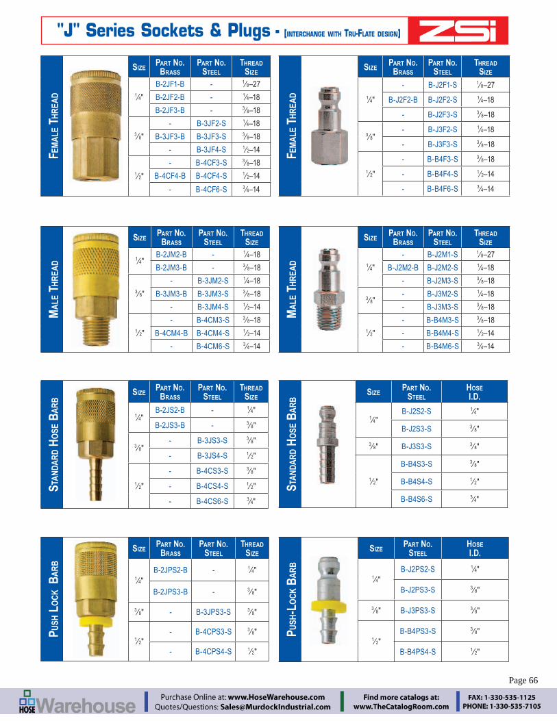
– 66 – www.zsi-inc.com
FEM
ALE
TH
REA
DSIZE
PART NO.BRASS
PART NO. STEEL
THREAD SIZE
14"
B-2JF1-B - 18–27
B-2JF2-B - 14–18
B-2JF3-B - 38–18
38"
- B-3JF2-S 14–18
B-3JF3-B B-3JF3-S 38–18
- B-3JF4-S 12–14
12"
- B-4CF3-S 38–18
B-4CF4-B B-4CF4-S 12–14
- B-4CF6-S 34–14
MA
LE T
HR
EAD
SIZEPART NO.
BRASSPART NO.
STEELTHREAD
SIZE
14"
B-2JM2-B - 14–18
B-2JM3-B - 38–18
38"
- B-3JM2-S 14–18
B-3JM3-B B-3JM3-S 38–18
- B-3JM4-S 12–14
12"
- B-4CM3-S 38–18
B-4CM4-B B-4CM4-S 12–14
- B-4CM6-S 34–14
STA
NDA
RD H
OSE
BA
RB
SIZEPART NO.
BRASSPART NO.
STEELTHREAD
SIZE
14"
B-2JS2-B - 14"
B-2JS3-B - 38"
38"
- B-3JS3-S 38"
- B-3JS4-S 12"
12"
- B-4CS3-S 38"
- B-4CS4-S 12"
- B-4CS6-S 34"
PUSH
LO
CK B
AR
B
SIZEPART NO.
BRASSPART NO.
STEELTHREAD
SIZE
14"
B-2JPS2-B - 14"
B-2JPS3-B - 38"
38" - B-3JPS3-S 3
8"
12"
- B-4CPS3-S 38"
- B-4CPS4-S 12"
FEM
ALE
TH
REA
D
SIZEPART NO.
BRASSPART NO.
STEELTHREAD
SIZE
14"
- B-J2F1-S 18–27
B-J2F2-B B-J2F2-S 14–18
- B-J2F3-S 38–18
38"
- B-J3F2-S 14–18
- B-J3F3-S 38–18
12"
- B-B4F3-S 38–18
- B-B4F4-S 12–14
- B-B4F6-S 34–14
MA
LE T
HR
EAD
SIZEPART NO.
BRASSPART NO.
STEELTHREAD
SIZE
14"
- B-J2M1-S 18–27
B-J2M2-B B-J2M2-S 14–18
- B-J2M3-S 38–18
38"
- B-J3M2-S 14–18
- B-J3M3-S 38–18
12"
- B-B4M3-S 38–18
- B-B4M4-S 12–14
- B-B4M6-S 34–14
STA
NDA
RD H
OSE
BA
RB
SIZEPART NO.
STEELHOSE I.D.
14"
B-J2S2-S 14"
B-J2S3-S 38"
38" B-J3S3-S 3
8"
12"
B-B4S3-S 38"
B-B4S4-S 12"
B-B4S6-S 34"
PUSH
-LO
CK B
AR
B
SIZEPART NO.
STEELHOSE I.D.
14"
B-J2PS2-S 14"
B-J2PS3-S 38"
38" B-J3PS3-S 3
8"
12"
B-B4PS3-S 38"
B-B4PS4-S 12"
"J" Series Sockets & Plugs - [INTERCHANGE WITH TRU-FLATE DESIGN]
Page 66
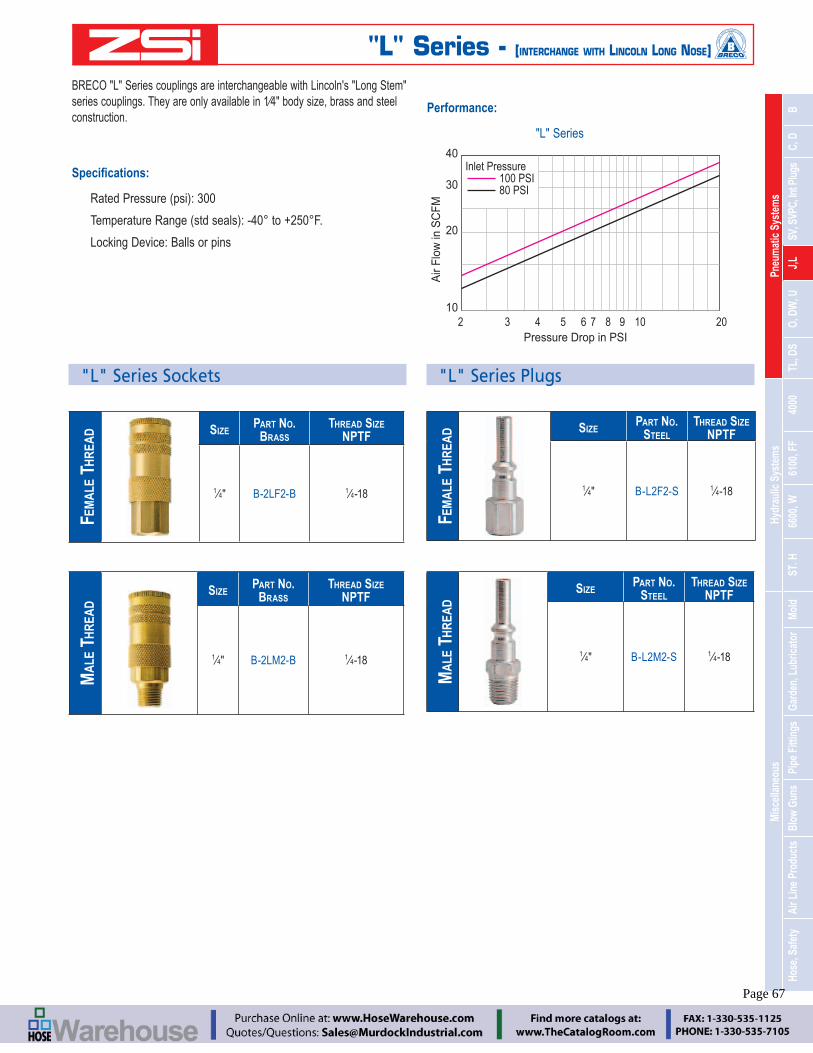
Mis
cella
neou
sHy
drau
lic S
yste
ms
Pneu
mat
ic S
yste
ms
Hose
, Saf
ety
Air L
ine
Prod
ucts
Blow
Gun
sPi
pe F
ittin
gsGa
rden
, Lub
ricat
orM
old
ST. H
6600
, W61
00, F
F40
00TL
, DS
O, D
W, U
J,L
SV, S
VPC,
Int P
lugs
C, D
B
Engineering Catalog www.zsi-inc.com – 67 –
BRECO "L" Series couplings are interchangeable with Lincoln's "Long Stem"
construction.
Locking Device: Balls or pins
Performance:
"L" Series
20
10
40
30
2 3 4 5 6 7 8 9 10 20Pressure Drop in PSI
Air
Flow
in S
CFM
Inlet Pressure 100 PSI 80 PSI
"L" Series Sockets
FEM
ALE
TH
REA
D SIZEPART NO.
BRASSTHREAD SIZE
NPTF
14" B-2LF2-B 1
4-18
MA
LE T
HR
EAD
SIZEPART NO.
BRASS THREAD SIZE
NPTF
14" B-2LM2-B 1
4-18
"L" Series Plugs
FEM
ALE
TH
REA
D SIZEPART NO.
STEELTHREAD SIZE
NPTF
14" B-L2F2-S 1
4-18
MA
LE T
HR
EAD
SIZEPART NO.
STEELTHREAD SIZE
NPTF
14" B-L2M2-S 1
4-18
"L" Series - [INTERCHANGE WITH LINCOLN LONG NOSE]
Page 67

– 68 – www.zsi-inc.com
BRECO “O” Series couplings are manual to connect designs and interchange with ¼” body size ARO 210 series plugs.
Rated Pressure: 300 psi
Locking Device: Stainless Steel pins
All Brass construction
Performance:
"O" Series
20
10
40
30
20
10
40
30
2 3 4 5 6 7 8 9 10 20 Pressure Drop in PSI
Air F
low
in S
CFM
Inlet Pressure 100 PSI 80 PSI
FEM
ALE
TH
REA
D
SIZEPART NO.
BRASSPART NO.
STEELTHD SIZE NPTF
14"
B-2OF2-B - 14–18
B-2OF3-B - 38–18
- B-2OF2-S 14–18
38" B-3OF3-B - 3
8–18
MA
LE T
HR
EAD
SIZEPART NO.
BRASSPART NO.
STEELTHD SIZE NPTF
14"
B-2OM2-B - 14–18
B-2OM3-B - 38–18
- B-2OM2-S 14–18
38" B-3OM3-S 3
8-27
STA
NDA
RD H
OSE
BA
RB SIZE
PART NO.BRASS
HOSE I.D.
14"
B-2OS2-B 14"
B-2OS3-B 38"
PUSH
-LO
CK H
OSE
BA
RB SIZE
PART NO.BRASS
HOSE I.D.
14"
B-2OPS2-B 14"
B-2OPS3-B 38"
*Push-Lock hose barbs are designed for use with Push-Lock hose and do not require clamps.
FEM
ALE
PIP
E TH
REA
D SIZEPART NO.
STEEL THREAD SIZE NPTF
14"
B-O2F2-S 14-18
B-O2F3-S 38-18
38" B-O3F3-S 3
8-18 MA
LE P
IPE
THR
EAD SIZE
PART NO. STEEL THREAD SIZE NPTF
14"
B-O2M1-S 18"
B-O2M2-S 14-18
B-O2M3-S 38-18
38" B-O3M3-S 3
8-18
STA
NDA
RD H
OSE
BA
RB SIZE
PART NO. STEEL
HOSE I.D.
14"
B-O2S2-S 14"
B-O2S3-S 38"
PUSH
-LO
K H
OSE
BA
RB SIZE
PART NO. STEEL
HOSE I.D.
14" B-O2PS2-S 1
4"
"O" Series - [INTERCHANGE WITH ARO 210]
Page 68
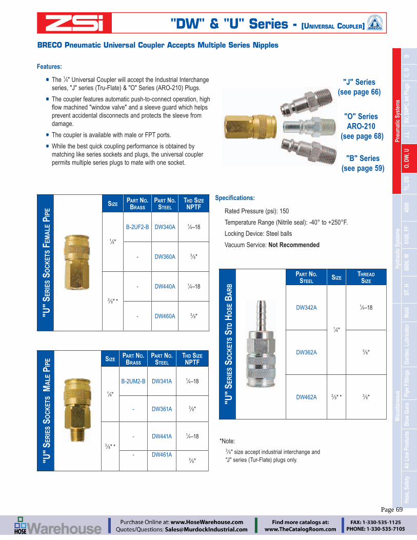
Mis
cella
neou
sHy
drau
lic S
yste
ms
Pneu
mat
ic S
yste
ms
Hose
, Saf
ety
Air L
ine
Prod
ucts
Blow
Gun
sPi
pe F
ittin
gsGa
rden
, Lub
ricat
orM
old
ST. H
6600
, W61
00, F
F40
00TL
, DS
O, D
W, U
J,L
SV, S
VPC,
Int P
lugs
C, D
B
Engineering Catalog www.zsi-inc.com – 69 –
BRECO Pneumatic Universal Coupler Accepts Multiple Series Nipples
Features:
The 14" Universal Coupler will accept the Industrial Interchange
The coupler features automatic push-to-connect operation, high
prevent accidental disconnects and protects the sleeve from damage.
The coupler is available with male or FPT ports.
While the best quick coupling performance is obtained by matching like series sockets and plugs, the universal coupler permits multiple series plugs to mate with one socket.
BODY SIZE 1
4"
Locking Device: Steel balls
Vacuum Service: Not Recommended
"U"
SER
IES
SOC
KET
S M
ALE
PIP
E SIZEPART NO.
BRASSPART NO.
STEELTHD SIZENPTF
14"
B-2UM2-B DW341A 14–18
- DW361A 38"
38" *
- DW441A 14–18
- DW461A3
8"
"U"
SER
IES
SOC
KET
S FE
MA
LE P
IPE
SIZEPART NO.
BRASSPART NO.
STEELTHD SIZENPTF
14"
B-2UF2-B DW340A 14–18
- DW360A 38"
38" *
- DW440A 14–18
- DW460A 38"
"B" Series (see page 59)
"J" Series (see page 66)
"O" Series ARO-210
(see page 68)
"U"
SER
IES
SOC
KET
S ST
D H
OSE
BA
RB
PART NO. STEEL
SIZETHREAD
SIZE
DW342A
14"
14–18
DW362A 38"
DW462A 38" * 3
8"
"DW" & "U" Series - [UNIVERSAL COUPLER]
*Note:
38" size accept industrial interchange and
Page 69

– 70 – www.zsi-inc.com
Push to Connect/Lock...Twist to Unlock
Features
Engineered for speedy coupling and uncoupling.
To lock - push in;
To unlock - give the coupler unit sleeve a 18" turn.
Designed to protect against accidental uncoupling. A variety of
Standard Twist-Lock couplings are ideal for low to medium air
Size 14"
Rated Pressure (psi): 250
Temperature Range (Nitrile seal):
Locking Device: Twist-Lock
Vacuum Service: 27 HG
Materials:
Aluminum bodies and zinc plated steel sleeves. Buna-N seals. Brass adapters.
Performance:
20
10
30
78
20
10
30
78
2 3 4 5 6 7 8 9 10 201
Flow
in S
CFM
Pressure Drop in PSI
Inlet Pressure 100 PSI 80 PSI
FEM
ALE
TH
REA
D
SIZE PART NO. THREAD SIZE NPT
14"
B-2TLF1-S 18"
B-2TLF2-S 14"
B-2TLF3-S 38"
12"
B-4TLF2-S 14"
B-4TLF3-S 38"
B-4TLF4-S 12"
B-4TLF6-S 34"
"TL" Series SocketsST
D. H
OSE
BA
RB SIZE PART NO. THREAD SIZE
NPT
14" B-TL2S2-S 1
4"
MA
LE T
HR
EAD
SIZE PART NO. THREAD SIZE NPT
14"
B-TL2M1-S 1
B-TL2M2-S 14"
12"
B-TL4M2-S 14"
B-TL4M3-S 38"
B-TL4M4-S 12"
B-TL4M6-S 34"
FEM
ALE
TH
REA
D
SIZE PART NO. THREAD SIZE NPT
14"
B-TL2F1-S 18"
B-TL2F2-S 14"
12"
B-TL4F2-S 14"
B-TL4F3-S 38"
"TL" Series Plugs
MA
LE T
HR
EAD
SIZE PART NO. THREAD SIZE NPT
14"
B-2TLM2-S 14"
B-2TLM3-S 38"
12"
B-4TLM2-S 14"
B-4TLM3-S 38"
B-4TLM4-S 12"
"TL" Series - [STANDARD AND HEAVY DUTY SCHRADER INTERCHANGE]
Page 70

Mis
cella
neou
sHy
drau
lic S
yste
ms
Pneu
mat
ic S
yste
ms
Hose
, Saf
ety
Air L
ine
Prod
ucts
Blow
Gun
sPi
pe F
ittin
gsGa
rden
, Lub
ricat
orM
old
ST. H
6600
, W61
00, F
F40
00TL
, DS
O, D
W, U
J,L
SV, S
VPC,
Int P
lugs
C, D
B
Engineering Catalog www.zsi-inc.com – 71 –
Features:
1. ISO B, Hardened plugs and sleeves along with solid bar stock construction assures long service life by providing maximum resis-tance to damage caused by hydraulic and mechanical shock.
2.
3. BRECO’s conical valve with its 360° metal to metal valve stop maintains valve alignment and insures that poppets open fully every time.
4. Captive valve seal assures "bubble tight" poppet sealing. The valve seal is positively captured by the metal poppet to minimize
5. Durable ball locking mechanism assures reliable connections every time. Many ball bearing distribute the load while providing alignment and excellent swiveling action to reduce hose torque and prolong hose life.
6. Broad range of metals and seal materials allow the use of most
7. Industry-wide interchangeability with most major manufacturers
market.
Applications
"DS" Series sockets incorporate valves in both socket and plug
sockets are normally referred to as "hydraulic couplings", but they are used extensively with other media where objectionable. The "DS" Series sockets are available in ROHS compliant steel and brass.
Interchangeability
"DS" Series couplings are known as "Industrial Interchange" couplings because they are dimensionally and operationally inter-changeable with similar couplings of the same size manufactured by others.
RATED PRESSURE, COUPLED
SIZEBRASS STEEL STAINLESS STEEL
PSI BAR PSI BAR PSI BAR1DS 1
8" 3,000 207 4,000 275 5,000 3442DS 1
4" 2,700 186 3,700 225 3,700 2553DS 3
8" 2,200 152 3,700 255 3,700 2554DS 1
2" 2,250 155 5,000 345 4,250 2936DS 3
4" 2,000 138 4,000 275 3,500 2428DS 1" 1,500 103 4,000 275 2,500 173
2
1
34579
10
20
50
30
50
1DS
2DS
3DS
4DS
6DS
8DS
40 30 20 10 7 5 3 2 1 0.7 0.5 100 70
Flow Rate, gpm
(Hydraulic Oil at 100°F)
Pres
sure
Dro
p, P
SI
1
12
2
4
35
6
7
Performance:
"DS" Series Double ShutOff [ISO 7241-1 SERIES B]
Page 71

– 72 – www.zsi-inc.com
Ordering Information:
"DS" Series couplings are available in ROHS compliant plated steel, brass, and 303 stainless steel as standard. Brass couplings have
are available, consult factory.
Example 2DSF2-B-SL.
40
30
20
1/2" 1" 10 8
6
4 3
2
1
40
30
20
10 8
6
4 3
2
1 40 60 80 20 10 8 7 6 5 4 3 2 1
3/8" 3/4"
SIZE
DUST PLUG PART NO.
DUST CAP PART NO.
ALUMINUM POLYURETHANE ALUMINUM POLYURETHANE1
8" BH1-65 BH1-65M BH1-66 BH1-66M1
4" BH2-65 BH2-65M BH2-66 BH2-66M3
8" BH3-65 BH3-65M BH3-66 BH3-66M1
2" BH4-65 BH4-65M BH4-66 BH4-66M3
4" BH6-65 BH6-65M BH6-66 BH6-66M1" BH8-65 BH8-65M BH8-66 BH8-66M
Performance:
DS Series 38" to 1"
Test Fluid: Oil-200 SUS
Dust Plugs and Dust Caps Features:
BRECO offers a complete line of dust plugs and caps for their hydraulic quick couplings. Each series shown in this catalog
that style of coupling.
Protective dust plugs and caps play a crucial role in the use of quick couplings and no purchase of a hydraulic quick coupling is complete without the selection of an appropriate dust plug and cap. When ordering the dust cap/plug body size must correspond to that of the socket or plug.
Dust plugs and caps serve a two-fold function. They keep the mating surface clean and free of contamination and protect the critical mating elements of the coupling halves when they are disconnected. In this way the plug is protected from damage that would make the total coupling unusable.
FEM
ALE
TH
REA
D SIZE PART NO. THREAD
SIZENPTFBRASS STEEL
TYPE 303 STAINLESS
18" 1DSF1-B 1DSF1-S 1DSF1-SS 1
8-271
4"2DSF2-B 2DSF2-S 2DSF2-SS 1
4-182DSF2-BI - - 1
4-183
8" 3DSF3-B 3DSF3-S 3DSF3-SS 38-18
12" 4DSF4-B 4DSF4-S 4DSF4-SS 1
2-143
4" 6DSF6-B 6DSF6-S 6DSF6-SS 34-14
1 8DSF8-B 8DSF8-S 8DSF8-SS 1-11 1 2
FEM
ALE
TH
REA
D SIZE
PART NO. THREAD SIZE
NPTFBRASS STEELTYPE 303 STAINLESS
18" DS1F1-B DS1F1-S DS1F1-SS 1
8-271
4"DS2F2-B DS2F2-S DS2F2-SS 1
4-18DS2F2-BI - - 1
4-183
8" DS3F3-B DS3F3-S DS3F3-SS 38-18
12" DS4F4-B DS4F4-S DS4F4-SS 1
2-143
4" DS6F6-B DS6F6-S DS6F6-SS 34-14
1" DS8F8-B DS8F8-S DS8F8-SS 1-11 12
"DS" Series Sockets "DS" Series Plugs
Note: Plug DS2F2-BI for Carpet Cleaners (Standard EPDM Seals)
Contact Factory for larger sizes
Note: Socket 2DSF2-BI for Carpet Cleaners (Standard EPDM Seals)
Contact Factory for larger sizes
Flow in USGPM
Pres
sure
Dro
p in
PD
I"DS" Series Double ShutOff - [ISO 7241-1 SERIES B]
Page 72
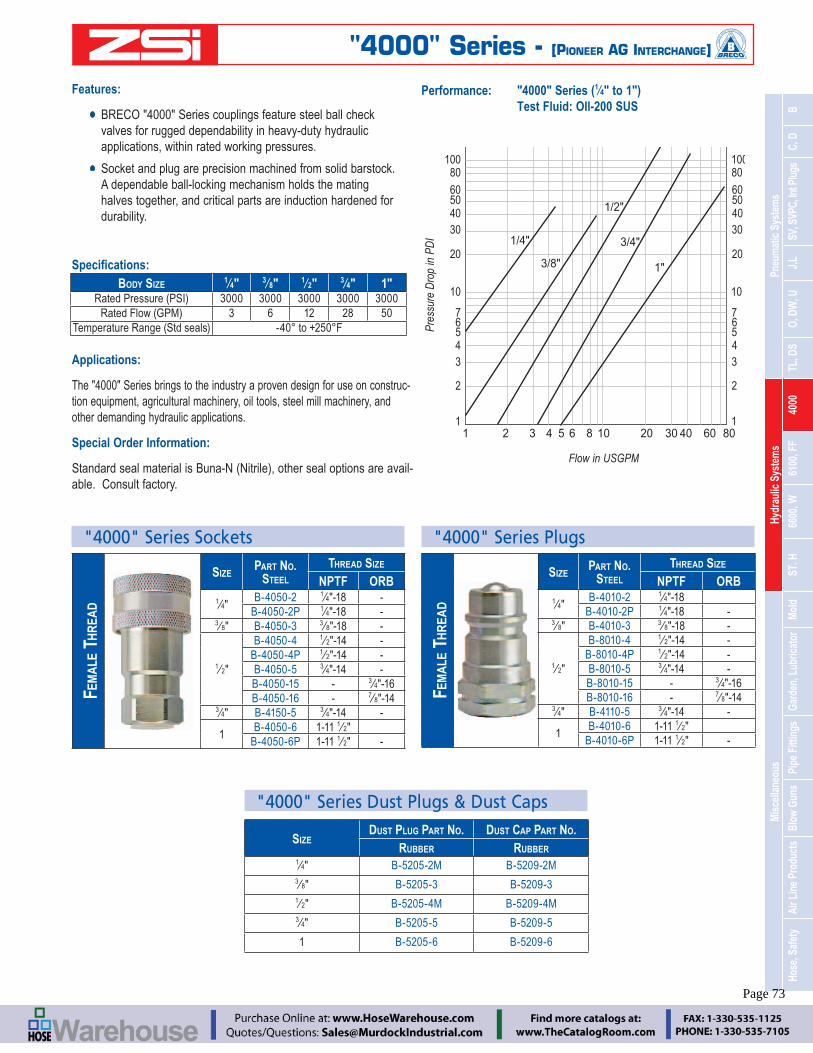
Mis
cella
neou
sHy
drau
lic S
yste
ms
Pneu
mat
ic S
yste
ms
Hose
, Saf
ety
Air L
ine
Prod
ucts
Blow
Gun
sPi
pe F
ittin
gsGa
rden
, Lub
ricat
orM
old
ST. H
6600
, W61
00, F
F40
00TL
, DS
O, D
W, U
J,L
SV, S
VPC,
Int P
lugs
C, D
B
Engineering Catalog www.zsi-inc.com – 73 –
Features:
BRECO "4000" Series couplings feature steel ball check valves for rugged dependability in heavy-duty hydraulic applications, within rated working pressures.
Socket and plug are precision machined from solid barstock. A dependable ball-locking mechanism holds the mating halves together, and critical parts are induction hardened for durability.
Applications:
The "4000" Series brings to the industry a proven design for use on construc-tion equipment, agricultural machinery, oil tools, steel mill machinery, and other demanding hydraulic applications.
Special Order Information:
-able. Consult factory.
Performance: "4000" Series (14" to 1")
Test Fluid: OIl-200 SUS
BODY SIZE 14" 3
8" 12" 3
4" 1"3000 3000 3000 3000 3000
3 6 12 28 50
21 3 4 5 6 8 10 20 40 30 60 80 1
2
34567
10
20
40 30
60 50
80 100
1
2
34567
10
20
4030
6050
80100
1/4" 3/4"
1/2"
1"3/8"
SIZE DUST PLUG PART NO. DUST CAP PART NO.
RUBBER RUBBER1
4" B-5205-2M B-5209-2M3
8" B-5205-3 B-5209-31
2" B-5205-4M B-5209-4M3
4" B-5205-5 B-5209-5
1 B-5205-6 B-5209-6
FEM
ALE
TH
REA
D
SIZE PART NO. STEEL
THREAD SIZE
NPTF ORB1
4"B-4050-2 1
4"-18 -B-4050-2P 1
4"-18 -3
8" B-4050-3 38"-18 -
12"
B-4050-4 12"-14 -
B-4050-4P 12"-14 -
B-4050-5 34"-14 -
B-4050-15 - 34"-16
B-4050-16 - 78"-14
34" B-4150-5 3
4"-14 -
1B-4050-6 1-11 1 2"
B-4050-6P 1-11 12" -
"4000" Series Sockets "4000" Series Plugs
FEM
ALE
TH
REA
D
SIZE PART NO. STEEL
THREAD SIZE
NPTF ORB1
4"B-4010-2 1
4"-18B-4010-2P 1
4"-18 -3
8" B-4010-3 38"-18 -
12"
B-8010-4 12"-14 -
B-8010-4P 12"-14 -
B-8010-5 34"-14 -
B-8010-15 - 34"-16
B-8010-16 - 78"-14
34" B-4110-5 3
4"-14 -
1B-4010-6 1-11 1
2"B-4010-6P 1-11 1
2" -
"4000" Series Dust Plugs & Dust Caps
Flow in USGPM
Pres
sure
Dro
p in
PD
I
"4000" Series - [PIONEER AG INTERCHANGE]
Page 73

– 74 – www.zsi-inc.com
SIZE3
4" 34" 1 11
4" 112"
Dash Number -08 -12 -16 -20 -24
Female Half 3000 3000 3000 2750 2000Male Half 3000 3000 3000 2500 2500
Complete Coupling Assembly 3000 3000 3000 2750 2500
12 28 50 76 100*Minimum burst pressure is equal to three times the rated pressure.
Not recommended for continuous hydraulic impulse applications at rated pressures.
Performance:
"6100" Series (12" to 1-1
2") Test Fluid: OIL-200 SUS
CO
UPL
ING W
ITH W
ING N
UT
SIZETHREAD
SIZE NPTF
PART NO.WITH
FLANGEWITHOUT FLANGE
34"
12-14 B-6100-08 B-6120-08
34-14 B-6100-12 B-6120-12
1" 1 -1112 B-6100-16 B-6120-16
1 14" 1 1
4 -1112 B-6100-20 B-6120-20
1 12" 1 1 2 -111
2 B-6100-24 B-6120-24
CO
UPL
ING W
ITH H
EX N
UT
SIZETHREAD
SIZE NPTF
PART NO.WITH
FLANGEWITHOUT FLANGE
34"
12-14 B-6110-08 B-6130-08
34-14 B-6110-12 B-6130-12
1" 1 -1112 B-6110-16 B-6130-16
1 1 4" 1 14 -111
2 B-6110-20 B-6130-20
1 12" 1 1 2 -111
2 B-6110-24 B-6130-24
2
2
13
3
4
4
5 6
6
7 8
8
10
10
20
20
40 30
30
50 100
2
1
346810
2030
150 70
1/2"
3/4"
1" 1 1/2"1 1/4"
Flow in USGPM
Pres
sure
Dro
p in
PD
I
"6100" Series Coupling Assemblies
Sockets
WIN
G N
UT SIZE
PART NO. BRASS
THREAD SIZE NPTF
34"
B-6125-08 12-14
B-6125-12 34-14
1" B-6125-16 1 -11 12
1 14" B-6125-20 11
4-11 12
1 12" B-6125-24 11
2-11 12
HEX
NU
T
SIZEPART NO.
BRASSTHREAD SIZE
NPTF3
4"B-6135-08 1
2-14B-6135-12 3
4-141" B-6135-16 1 -11 1
2
1 14" B-6135-20 11
4-11 12
1 12" B-6135-24 11
2-11 12
Plugs
Dust Plugs & Dust Caps
SIZEDUST PLUG
PART NO. - BRASSDUST CAP
PART NO. - BRASS3
4" B-6109-08 B-6108-081" B-6109-16 B-6108-16
1 14" B-6109-20 B-6108-20
1 1 2" B-6109-24 B-6108-24
OPT
ION
AL
FLA
NG
E SIZE PART NO. - STEEL
34" B-6107-08
1" B-6107-16
1 14" B-6107-20
1 1 2" B-6107-24
PLU
G
SIZE PART NO. - BRASS THREAD
SIZE NPTF
WITHOUT FLANGE
WITH FLANGE
34"
B-6105-08 B-6115-08 12-14
B-6105-12 B-6115-12 34-14
1" B-6105-16 B-6115-16 1 -11 12
1 14" B-6105-20 B-6115-20 11
4-11 12
1 12" B-6105-24 B-6115-24 11
2-11 12
"6100" Series - [Wing Nut]
Page 74
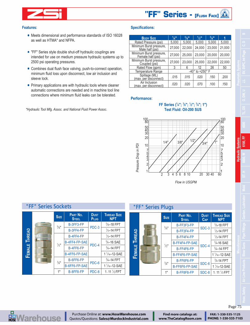
Mis
cella
neou
sHy
drau
lic S
yste
ms
Pneu
mat
ic S
yste
ms
Hose
, Saf
ety
Air L
ine
Prod
ucts
Blow
Gun
sPi
pe F
ittin
gsGa
rden
, Lub
ricat
orM
old
ST. H
6600
, W61
00, F
F40
00TL
, DS
O, D
W, U
J,L
SV, S
VPC,
Int P
lugs
C, D
B
Engineering Catalog www.zsi-inc.com – 75 –
Features:
Meets dimensional and performance standards of ISO 16028 as well as HTMA* and NFPA.
"FF" Series style double shut-off hydraulic couplings are intended for use on medium pressure hydraulic systems up to 2500 psi operating pressures.
sleeve lock.
Primary applications are with hydraulic tools where cleaner automatic connections are needed and in machine tool line
*Hydraulic Tool Mfg. Assoc. and National Fluid Power Assoc.
BODY SIZE 14" 3
8" 12" 3
4" 15,000 5,000 5,000 5,000 5,000
Minimum Burst pressure, 27,000 22,000 24,000 23,000 21,000
Minimum Burst pressure, 27,000 25,000 23,000 20,000 20,000
Minimum Burst pressure, 27,000 23,000 25,000 22,000 22,000
3 6 12 26 50Temperature Range
.015 .015 .020 .150 .200
Air Inclusion .020 .020 .070 .100 .150
FEM
ALE
TH
REA
D
SIZEPART NO.
STEELDUST CAP
THREAD SIZE NPT
38"
B-FF3F3-FPSDC-3
38-18 FPT
B-FF3F4-FP 12-14 FPT
12"
B-FF4F4-FP
SDC-4
12-14 FPT
B-FF4F4-FP-SAE 34-16 SAE
B-FF4F6-FP 34–14 FPT
B-FF4F6-FP-SAE 1 1 16–12-SAE
34"
B-FF6F6-FPSDC-6
34-14 FPT
B-FF6F6-FP-SAE 1 116-12-SAE
1" B-FF8F8-FP SDC-8 1 - 11 12 FPT
Performance:
FF Series (14"; 3
8"; 12"; 3
4"; 1") Test Fluid: Oil-200 SUS
2 3 4 5 6 8 10 20 40 30 60 1
2345710
20 3/8" 1" 1/2"
3/4" 1/4"
40 30
50
80 100
1
23457
10
20
4030
50
80100
"FF" Series Sockets
FEM
ALE
TH
REA
D
SIZEPART NO.
STEELDUST PLUG
THREAD SIZE NPT
38"
B-3FF3-FPPDC-3
38–18 FPT
B-3FF4-FP 12–14 FPT
12"
B-4FF4-FP
PDC-4
12–14 FPT
B-4FF4-FP-SAE 34–16 SAE
B-4FF6-FP 34–14 FPT
B-4FF6-FP-SAE 1 1 16–12-SAE
34"
B-6FF6-FPPDC-6
34–14 FPT
B-6FF6-FP-SAE 1 1 16–12-SAE
1" B-8FF8-FP PDC-8 1 - 11 12 FPT
"FF" Series Plugs
Flow in USGPM
Pres
sure
Dro
p in
PD
I
"FF" Series - [FLUSH FACE]
Page 75

– 76 – www.zsi-inc.com
Applications:
The versatile "6600" Series couplings are used in a wide range of hydraulic applications including construction equipment, manufactur-ing machinery, and in-plant systems. They can be found anywhere
for operation or maintenance of equipment. Rugged construction makes it a good choice for mobile applications including dump trucks, snow plows, refuse hauling, mining, asphalt paving, truck trailer connections and many more. In-plant machinery applications
production, and many varieties of plant maintenance and production equipment.
Features:
BRECO "6600" Series couplings feature poppet valves with solid metal perch that maintains valve alignment and prevents
case hardened to make the couplings resistant to damage from brinelling and mechanical shock.
The durable ball-locking mechanism ensures a reliable connec-tion every time.
These couplings have female pipe and straight thread end
Series A in ISO 7241-1. Socket and plug are interchangeable with other parts compatible with ISO 7241-1.
SIZE1
4" 38" 1
2" 34" 1
Working Pressure 5000 4000 4000 4000 4000 Temperature Range
1
2
21 3
3
4
4
5
5
6
6
7
7
89
9
10
10
20
20
40
40
30
30
60
60
50
50
80 100
80 100
3/8"
1/4"
3/4"
1/2"
1"
Series “6600” 1/4"Test Fluid: Oil-200 SUS
Pres
sure
Dro
p in
PSI
Flow in US Gal/Min
"6600" Series Sockets
FEM
ALE
TH
REA
D
SIZE PART NO. STEEL
THREAD SIZE NPTF ORB
14"
B-6601-2-4 18-27 -
B-6601-4-4 14-18 -
38" B-6601-6-6 3
8-18 916-18
12"
B-6601-8-10 12-14 -
B-6601-12-10 34-14 -
B-6608-8-10 - 34-16
B-6608-10-10 - 12-12
B-6608-12-10 - 1 116-12
34"
B-6601-12-12 34-14 1 1
16-12 B-6608-12-12 - -
1"B-6601-16-16 1 - 11 1
2
B-6608-16-16 - 1 5 16-12
FEM
ALE
TH
REA
D
SIZE PART NO. STEEL
THREAD SIZE NPTF ORB
14"
B-6602-2-4 18-27 -
B-6602-4-4 14-18 -
38" B-6602-6-6 3
8-18 -
12"
B-6602-8-10 12-14 -
B-6602-12-10 34-14 -
B-6610-6-6 - 916-18
B-6610-8-10 - 34-16
B-6610-10-10 - 78-14
B-6610-12-10 - 1 116-12
34"
B-6602-12-12 34-14 -
B-6610-12-12 - 1 116-12
1"B-6602-16-16 1 - 11 1
2
B-6610-16-16 - 1 516-12
"6600" Series PlugsDust Plugs & Dust Caps
SIZE DUST PLUG PART NO.
DUST CAP PART NO.
14" B-6659-4 B-6657-4
38" B-6659-6 B-6657-6
12" B-6659-10 B-6657-10
34" B-6659-12 B-6657-12
1" B-6659-16 B-6657-16
"6600" Series - [ISO 7241-1 SERIES A]
Page 76

Mis
cella
neou
sHy
drau
lic S
yste
ms
Pneu
mat
ic S
yste
ms
Hose
, Saf
ety
Air L
ine
Prod
ucts
Blow
Gun
sPi
pe F
ittin
gsGa
rden
, Lub
ricat
orM
old
ST. H
6600
, W61
00, F
F40
00TL
, DS
O, D
W, U
J,L
SV, S
VPC,
Int P
lugs
C, D
B
Engineering Catalog www.zsi-inc.com – 77 –
Features:
1. Machined from solid steel bar stock for durability.
2. The "W" Series has a threaded sleeve locking mechanism, mates with matching male threads on the plug. The two halves must be manually threaded together for connection.
3. Hard, chrome alloy balls are used for valving. They are spring loaded for positive sealing of the valve.
4. The valve provides a metal-to-metal seal between the ball and a coined seat.
5. The body seal is polyurethane which resists high pressure extrusion.
6. A threaded valve retainer provides a valve stop that assures positive valve alignment.
Applications:
The "W" Series couplings with their threaded union locking system and precision ball-type check valves, are designed for extreme high pressure applications such as found on portable hydraulic rams.
SIZE1
4" 38"
10,000
1
1
3
2
4
5
6
Performance:
Note:
Protective dust plugs and caps play a crucial role in the life of a quick coupling and no purchase of a hydraulic quick coupling is complete without the selection of an appropriate dust plug and cap.
Dust Plugs & Dust Caps
SIZE DUST PLUG PART NO.
STEEL
DUST CAP PART NO.
STEEL1
4" B-3005-2 B-3009-23
8" B-3005-3 B-3009-3
"W" Series Sockets
SIZE PART NO. THREAD
SIZEVALVE NON-VALVE
14" B-2WM2-S B-2WEM2-S 1
4-18 Male
38"
B-3WM3-S B-3WEM3-S 38-18 Male
B-3WF3-S B-3WEF3-S 38 -18 Female
"W" Series Plugs
SIZE PARTNO. THREAD SIZE
NPFTVALVE NON-VALVE
14" B-W2F2-S B-W2EF2-S 1
4-18 Female
38" B-W3F3-S B-W3EF3-S 3
8-18 Female
2 3 4 5 61 8 9710
20
40
30
6050
80
100
150
10
20
40
30
6050
80
100
150
1/4"
3/8"
Series "W" (1/4", 3/8")Test Fluid: OIL-200 SUS
Pres
sure
Dro
p in
PSI
Flow In USGPM
"W" Series - [HIGH PRESSURE COUPLING, ENERPAC INTERCHANGE]
Page 77

– 78 – www.zsi-inc.com
SIZE1
8" 14" 3
8" 12" 3
4" 1 114" 11
2"
Brass 2500 5200 2700 2200 1700 1200 1700 1400Steel 2600 5500 3500 2700 2700 2000 - -
Stainless Steel 4200 6700 5500 3000 3000 1700 - -Temperature Range
Performance:
"ST" Series Sockets
FEM
ALE
TH
REA
D
SIZE
PART NO. THREAD SIZE
NPTFBRASSTYPE 303 STAINLESS
18" 1STF1-B 1STF1-SS 1
8-27
14" 2STF2-B 2STF2-SS 1
4-18
38" 3STF3-B 3STF3-SS 3
8 -18
12" 4STF4-B 4STF4-SS 1
2-14
34" 6STF6-B 6STF6-SS 3
4-14
1" 8STF8-B 8STF8-SS 1 -11 12
MA
LE T
HR
EAD
SIZE
PART NO. THREAD SIZE
NPTFBRASSTYPE 303 STAINLESS
18" 1STM1-B 1STM1-SS 1
8-271
4" 2STM2-B 2STM2-SS 14-18
38" 3STM3-B 3STM3-SS 3
8-181
2" 4STM4-B 4STM4-SS 12-14
34" 6STM6-B 6STM6-SS 3
4-14
1" 8STM8-B 8STM8-SS 1 -11 12
20
10
30 1/8" 1/4" 3/8"
543
2
1.1 .2 .4 .5 .8 1 2 4 6 8 10 20 30 50 100
68
1/2"
3/4" 1"
Pres
sure
Dro
p in
PSI
Flow in US Gal/Min
Series "ST"Test Fluid: OIL-200 SUS
FEM
ALE
TH
REA
D
SIZE
PART NO. THREAD SIZE
NPTFBRASS STEELTYPE 303 STAINLESS
18" ST1F1-B ST1F1-S ST1F1-SS 1
8 -27
14"
ST2F2-B ST2F2-S ST2F2-SS1
4-18- ST2F2-S-E -
38" ST3F3-B ST3F3-S ST3F3-SS 3
8-141
2" ST4F4-B ST4F4-S ST4F4-SS 12-14
34" ST6F6-B ST6F6-S ST6F6-SS 3
4-14
1" ST8F8-B ST8F8-S ST8F8-SS 1 -11 12
Note: ST2F2-S-E is extended plug
MA
LE T
HR
EAD
SIZE
PART NO. THREAD SIZE
NPTMBRASS STEELTYPE 303 STAINLESS
18" ST1M1-B ST1M1-S ST1M1-SS 1
8-271
4" ST2M2-B ST2M2-S ST2M2-SS 1
38" ST3M3-B ST3M3-S ST3M3-SS 3
8-141
2" ST4M4-B ST4M4-S ST4M4-SS 12-14
34" ST6M6-B ST6M6-S ST6M6-SS 3
4-14
1" ST8M8-B ST8M8-S ST8M8-SS 1 -11 12
"ST" Series - [STRAIGHT THRU DESIGN]
Page 78

Mis
cella
neou
sHy
drau
lic S
yste
ms
Pneu
mat
ic S
yste
ms
Hose
, Saf
ety
Air L
ine
Prod
ucts
Blow
Gun
sPi
pe F
ittin
gsGa
rden
, Lub
ricat
orM
old
ST. H
6600
, W61
00, F
F40
00TL
, DS
O, D
W, U
J,L
SV, S
VPC,
Int P
lugs
C, D
B
Engineering Catalog www.zsi-inc.com – 79 –
Socket Features:
Latch Mechanism
- Manual connect and disconnect
- Steel sleeves are hardened to provide maximum service life
Material and Finish
- Machined from solid bar stock
- Steel components are zinc plated
Coupled Seal
dynamic impulse
Plug Features:
Machined from solid bar stock
Steel plugs are hardened and zinc plated to provide heavy duty performance
double shut-off quick disconnects
Seals
- Valve seals are crimped in place to maintain integrity
Performance:
LATCH BALLS
MANUAL SLEEVE
O-RING SEAL WITHTEFLON BACK-UP RING
VALVE GUIDE
SOCKET VALVEWITH “WING”
CRIMPEDVALVE SLEEVE
VALVE STOPVALVEDCONFIGURATIONS
SHOWN
SOCKET
PLUG
1086
43
2
12 3 4 5 61 8 20 30 40 60 100 200
20
30
50
80100
200300
10
1/4" 1/2" 3/4"3/8"
Pres
sure
Dro
p in
PSI
Pressure Drop in US Gal/Min
Series “H” - Valved or Non-ValvedTest Fluid: Hydraulic Oil at 100°F
"H" Series - [INTERCHANGE WITH SNAPTITE SERIES H]
Page 79

– 80 – www.zsi-inc.com
"H" Series Sockets (with Valve)FE
MA
LE P
IPE
SIZENPT
THREAD SIZE
PART NO.
STEEL WITH VALVE
BRASS WITH VALVE
14" 1
4-18 B-VHC4-4F B-VHC4-4F-B
38" 3
8-18 B-VHC6-6F B-VHC6-6F-B
12" 1
2-14 B-VHC8-8F B-VHC8-8F-B
34" 3
4-14 B-VHC12-12F B-VHC12-12F-B
MA
LE P
IPE
SIZENPT
THREAD SIZE
PART NO.
STEEL WITH VALVE
BRASS WITH VALVE
14" 1
4-18 B-VHC4-4M B-VHC4-4M-B
38" 3
8-18 B-VHC6-6M B-VHC6-6M-B
12" 1
2-14 B-VHC8-8M B-VHC8-8M-B
34" 3
4-14 B-VHC12-12M B-VHC12-12M-B
"H" Series Sockets (non Valve)
FEM
ALE
PIP
E
SIZENPT
THREAD SIZE
PART NO.
STEEL NON-VALVE
BRASS NON-VALVE
14" 1
4-18 B-PHC4-4F B-PHC4-4F-B
38" 3
8-18 B-PHC6-6F B-PHC6-6F-B
12" 1
2-14 B-PHC8-8F B-PHC8-8F-B
34" 3
4-14 B-PHC12-12F B-PHC12-12F-B
MA
LE P
IPE
SIZENPT
THREAD SIZE
PART NO. STEEL
NON-VALVEBRASS
NON-VALVE
14" 1
4-18 B-PHC4-4M B-PHC4-4M-B
38" 3
8-18 B-PHC6-6M B-PHC6-6M-B
12" 1
2-14 B-PHC8-8M B-PHC8-8M-B
34" 3
4-14 B-PHC12-12M B-PHC12-12M-B
"H" Series Plugs (with Valve)
FEM
ALE
PIP
E
SIZETHREAD
SIZE
PART NO.
STEEL WITH VALVE
BRASS WITH VALVE
14" 1
4-18 B-VHN4-4F B-VHN4-4F-B
38" 3
8-18 B-VHN6-6F B-VHN6-6F-B
12" 1
2-14 B-VHN8-8F B-VHN8-8F-B
34" 3
4-14 B-VHN12-12F B-VHN12-12F-B
MA
LE P
IPE
SIZETHREAD
SIZE
PART NO.
STEEL WITH VALVE
BRASS WITH VALVE
14" 1
4-18 B-VHN4-4M B-VHN4-4M-B
38" 3
8-18 B-VHN6-6M B-VHN6-6M-B
12" 1
2-14 B-VHN8-8M B-VHN8-8M-B
34" 3
4-14 B-VHN12-12M B-VHN12-12M-B
"H" Series Plugs (non Valve)
FEM
ALE
PIP
E
SIZETHREAD
SIZE
PART NO.
STEEL NON-VALVE
BRASS NON-VALVE
14" 1
4-18 B-PHN4-4F B-PHN4-4F-B
38" 3
8-18 B-PHN6-6F B-PHN6-6F-B
12" 1
2-14 B-PHN8-8F B-PHN8-8F-B
34" 3
4-14 B-PHN12-12F B-PHN12-12F-B
MA
LE P
IPE
SIZETHREAD
SIZE
PART NO. STEEL
NON-VALVEBRASS
NON-VALVE
14" 1
4-18 B-PHN4-4M B-PHN4-4M-B
38" 3
8-18 B-PHN6-6M B-PHN6-6M-B
12" 1
2-14 B-PHN8-8M B-PHN8-8M-B
34" 3
4-14 B-PHN12-12M B-PHN12-12M-B
SIZE
STATIC PRESSURE RATING (PSI)—MATERIAL—
RATED FLOW (GPM)
VALVED NON-VALVEDBRASS STEEL1
4" 2,250 6,500 4.5 4.53
8" 2,250 4,500 6.5 6.51
2" 2,000 4,000 17 203
4" 2,000 3,500 35 40
"H" Series - [INTERCHANGE WITH SNAPTITE SERIES H]
Page 80

Mis
cella
neou
sHy
drau
lic S
yste
ms
Pneu
mat
ic S
yste
ms
Hose
, Saf
ety
Air L
ine
Prod
ucts
Blow
Gun
sPi
pe F
ittin
gsGa
rden
, Lub
ricat
orM
old
ST. H
6600
, W61
00, F
F40
00TL
, DS
O, D
W, U
J,L
SV, S
VPC,
Int P
lugs
C, D
B
Engineering Catalog www.zsi-inc.com – 81 –
1. Available with or without valves in the coupler. Non-valved couplers
shut off automatically upon disconnect. Valved couplers can be used with either valved or non-valved nipples. A valved nipple, however, must be used with a newly designed "AV" coupler.
2. Nipples are designed to be recessed below mold surfaces to provide
3. with standard hose barb or Push-Lok barbs for easy installation.
4. Couplers and nipples are made of corrosion resistant brass, and valved couplers or valved nipples have a Viton O-ring on poppet and Silicone interface seal as standard for use with water glycol (anti-
Applications
coolant lines to molds and dies, on injection molding machinery in the -
cantly reduce machine downtime by providing fast and easy connection of coolant lines during mold changes. Their short nipples can be recessed
Mold Series couplers are available with or without valves in the female half.
couplers shut off when disconnected.
Selection Guidelines
Injection Mold Series couplings are designed for a maximum working pressure of 200 PSI. Most thermoplastic and thermostat heat transfer
capacities ranging from 10 to 40 gpm, with most from 10 to 15 gpm Normal medial opening pressures are 20 to 60 PSI for these systems. Heat trans-fer systems using oil generally operate from 10 to 30 PSI. However, their
circulated at least once per minute.
The number of hose connections in a single mold system results in a cumu-lative pressure drop. Please note the Pressure Drop vs. Flow Rate chart provided, to select the appropriate size.
Temperature is another important consideration. Injection Mold Series cou-plings with their standard Silicone seal have a temperature capability of -90°
beyond these limits.
External conditions of temperature, corrosive atmospheres, and other ab-normalities may affect coupling performance and must be considered when selection is made consult factory with questions.
Performance:
Injection Mold Series (14"; 3
8"; 12")
8 10 20 6 4 2 1 .8
2
1
46810
20
504030
0.80.60.4
2
1
468
10
20
504030
0.80.60.4
1/4"
3/8"
1/2"
ValvedNon-Valved
Flow in USGPM
CB
Mold Counterbore
A
CAT. NO. NPT A B CB-PN251 1
8" .687 .687 1.000B-PN252 1
4" .843 .937 1.278B-PN253 3
8" 1.00 .937 1.373B-PN352 1
4" 1.00 1.092 1.450B-PN353 3
8" 1.00 1.125 1.574B-PN354 1
2" 1.187 1.250 –B-PN554 1
2" 1.250 1.500 1.750B-PN556 3
4" 1.500 1.562 1.750
PERFORMANCE DATAFLOW - WATER - GPM,
10 PSIG PRESSURE DROP
200 Series Straight-Thru 4.52.3
300 SeriesStraight-Thru 10.0
High Flow 13.85.9
500 Series Straight-Thru 28.2
Rated Pressure: 200 PSI
3
1
2
4
4
[INTERCHANGE WITH FOSTER FJT, DME JIFFY-TITE AND JIFFY-MATIC AND PARKER INJECTION MOLD SERIES]
Pres
sure
Dro
p in
PD
I
Injection Mold Series
Page 81

– 82 – www.zsi-inc.com
STR
AIG
HT
SIZE
PART NO.HOSE
IDBRASSNON-VALVED
BRASSWITH VALVE
14"
B-PC204 B-PC204AV 14"
B-PC204-BP PC204AV-BP 14"
B-PC205 B-PC205AV 516"
B-PC206 B-PC206AV 38"
B-PC206-BP B-PC206AV-BP 38"
38"
B-PC306 B-PC306V 38"
B-PC306-BP B-PC306V-BP 38"
B-PC308 B-PC308V 12"
B-PC308-BP B-PC308V-BP 12"
12"
B-PC504 - 12"
B-PC504-BP - 12"
B-PC506 - 34"
Injection Mold Series PlugsInjection Mold Series Sockets
FEM
ALE
PIP
E TH
REA
D
SIZEPART NO. THREAD
SIZE NPTFBRASS STEEL
14"
B-BPN251F B-PN251F 18"-27
B-BPN252F B-PN252F 14"-18
B-BPN253F B-PN253F 38"-18
38"
B-BPN352F B-PN352F 14"-18
B-BPN353F B-PN353F 38"-18
45 D
EGR
EE
SIZE
PART NO.HOSE
IDBRASSNON-VALVED
BRASSWITH VALVE
14"
B-PC224 B-PC224AV 14"
B-PC224-BP B-PC224AV-BP 14"
B-PC225 B-PC225AV 516"
B-PC226 B-PC226AV 38"
B-PC226-BP B-PC226AV-BP 38"
38"
B-PC326 B-PC326V 38"
B-PC326-BP B-PC326V-BP 38"
B-PC328 B-PC328V 12"
B-PC328-BP B-PC328V-BP 12"
90 D
EGR
EE
SIZE
PART NO.HOSE
IDBRASSNON-VALVED
BRASSWITH VALVE
14"
B-PC214 B-PC214AV 14"
B-PC214-BP B-PC214AV-BP 14"
B-PC215 B-PC215AV 516"
B-PC216 B-PC216AV 38"
B-PC216-BP B-PC216AV-BP 38"
38"
B-PC316 B-PC316V 38"
B-PC316-BP B-PC316V-BP 38"
B-PC318 B-PC318V 12"
B-PC318-BP B-PC318V-BP 12"
MA
LE P
IPE
THR
EAD
SIZEPART NO.
BRASSTHREAD SIZE
NPTF
14"
B-PN251 18"-27
B-PN252 14"-18
B-PN253 38"-18
38"
B-PN352 14"-18
B-PN353 38"-18
B-PN354 12"-14
12"
B-PN554 12"-14
B-PN556 34"-14
Injection Mold Series
Page 82

Mis
cella
neou
sHy
drau
lic S
yste
ms
Pneu
mat
ic S
yste
ms
Hose
, Saf
ety
Air L
ine
Prod
ucts
Blow
Gun
sPi
pe F
ittin
gsGa
rden
, Lub
ricat
orM
old
ST. H
6600
, W61
00, F
F40
00TL
, DS
O, D
W, U
J,L
SV, S
VPC,
Int P
lugs
C, D
B
Engineering Catalog www.zsi-inc.com – 83 –
Features:
Provides secure nipple-to-hose clamping. Made from high-quality bar stock.
In-Line Lubricators
Features:
Available in 12", 3
4" and 1" NPT pipe sizes.
Adapters may be used for smaller pipe diameters.
Simple, in-line installation.
Leak-proof, transparent sight disk allows visual oil level inspection.
Lightweight and portable.
Rugged construction, low maintenance.
Low cost
the adjustment valve with a screwdriver. The portable BL Series lubricators are ruggedly constructed of cast aluminum alloy and require minimal maintenance.
MODEL NO. BL-0 BL-1 BL-2 BL-3Pipe Size 1
2" NPT 34" NPT 3
4" NPT 1" NPT1.4 fl. oz. 3.7 fl. oz. 11 fl. oz. 17 fl. oz.
40 ml 110 ml 320 ml 480 ml500 260 300 250
Air Flow Cap 30 70 70 150
4 1 4" 6 7 102 1
4" 2 3 4" 3 12" 4 1 4"
2 14" 2 3 4" 3 3
4" 414 22 38 69
Features:
Brass and stainless steel construction for heavy duty service.
Durable 4-ball locking mechanism for secure connections.
Temperature-resistant BUNA seals for a leak-free service life.
Applications:
The Garden Hose couplings are used anywhere water hoses are connected and disconnected frequently. They are used on a wide variety of applications including garden hoses, wash down system, and mobile water tank lines. The unvalved design permits maximum
Body Size 34"
PLU
G
SIZEPART NO.
THREAD SIZE NH
34" B-7465 3
4-1112
SOC
KET
SIZEPART NO.
THREAD SIZE NH
34" B-7455 3
4-1112
Garden Hose Couplings
UpperReservoir
LowerReservoir
Oil Reservoir
Garden Hose, In-line Lubricators
Page 83

– 84 – www.zsi-inc.com
MA
LE P
USH
-LO
CK H
OSE
BA
RB
PART NO. HOSE I.D. NPT THREAD
POM-2-1 14" 1
8-27
POM-2-2 14" 1
4-18
POM-2-3 14" 3
8-18
POM-3-1 38" 1
8-27
POM-3-2 38" 1
4-18
POM-3-3 38" 3
8-18
POM-3-4 38" 1
2-14
POM-3-6 38" 3
4-14
POM-4-2 12" 1
4-18
POM-4-3 12" 3
8-18
POM-4-4 12" 1
2-14
POM-4-6 12" 3
4-14
POM-6-4 34" 1
2-14
POM-6-6 34" 3
4-14
FEM
ALE
PU
SH-L
OC
K H
OSE
BA
RB PART NO. HOSE I.D. NPT THREAD
POF-2-1 14" 1
8-27
POF-2-2 14" 1
4-18
POF-2-3 14" 3
8-18
POF-3-1 38" 1
8-27
POF-3-2 38" 1
4-18
POF-3-3 38" 3
8-18
POF-3-4 38" 1
2-14
POF-4-2 12" 1
4-18
POF-4-3 12" 3
8-18
POF-4-4 12" 1
2-14
POF-6-6 34" 3
4-14
HO
SE S
PLIC
ER P
USH
-LO
CK
PART NO. HOSE I.D.
POS-2-2 14"
POS-3-3 38"
POS-4-4 12"
POS-6-6 34"
REG
ULA
R H
OSE
SPL
ICER
PART NO. HOSE I.D.
HS-2-2 14"
HS-3-3 38"
HS-4-4 12"
MA
LE H
OSE
BA
RB
PART NO.
HOSE I.D.
NPT THREAD SIZE
HBM-1-1 18" 1
8-27
HBM-1-2 18" 1
4-18
HBM-25-1 316" 1
8-27
HBM-25-2 316" 1
4-18
HBM-2-1 14" 1
8-27
HBM-2-2 14" 1
4-18
HBM-2-3 14" 3
8-18
HBM-5-1 516" 1
8-27
HBM-5-2 516" 1
4-18
HBM-5-3 516" 3
8-18
HBM-3-1 38" 1
8-27
HBM-3-2 38" 1
4-18
HBM-3-3 38" 3
8-18
HBM-3-4 38" 1
2-14
HBM-3-6 38" 3
4-14
HBM-4-2 12" 1
4-18
HBM-4-3 12" 3
8-18
HBM-4-4 12" 1
2-14
HBM-4-6 12" 3
4-14
HBM-7-3 58" 3
8-18
HBM-7-4 58" 1
2-14
HBM-7-6 58" 3
4-14
HBM-6-4 34" 1
2-14
HBM-6-6 34" 3
4-14
HBM-8-6 1 34"-14
HBM-8-8 1 1 -11 12"
FEM
ALE
HO
SE B
AR
B
PART NO.
HOSE I.D.
NPT THREAD SIZE
HBF-1-1 18" 1
8-27
HBF-1-2 18" 1
4-18
HBF-25-1 316" 1
8-27
HBF-25-2 316" 1
4-18
HBF-2-1 14" 1
8-27
HBF-2-2 14" 1
4-18
HBF-2-3 14" 3
8-18
HBF-5-1 516" 1
8-27
HBF-5-2 516" 1
4-18
HBF-5-3 516" 3
8-18
HBF-3-1 38" 1
8-27
HBF-3-2 38" 1
4-18
HBF-3-3 38" 3
8-18
HBF-3-4 38" 1
2-14
HBF-4-2 12" 1
4-18
HBF-4-3 12" 3
8-18
HBF-4-4 12" 1
2-14
HBF-6-6 34" 3
4-14
Features:
Hose Barbs & Push-Lock Hose Barbs
Page 84
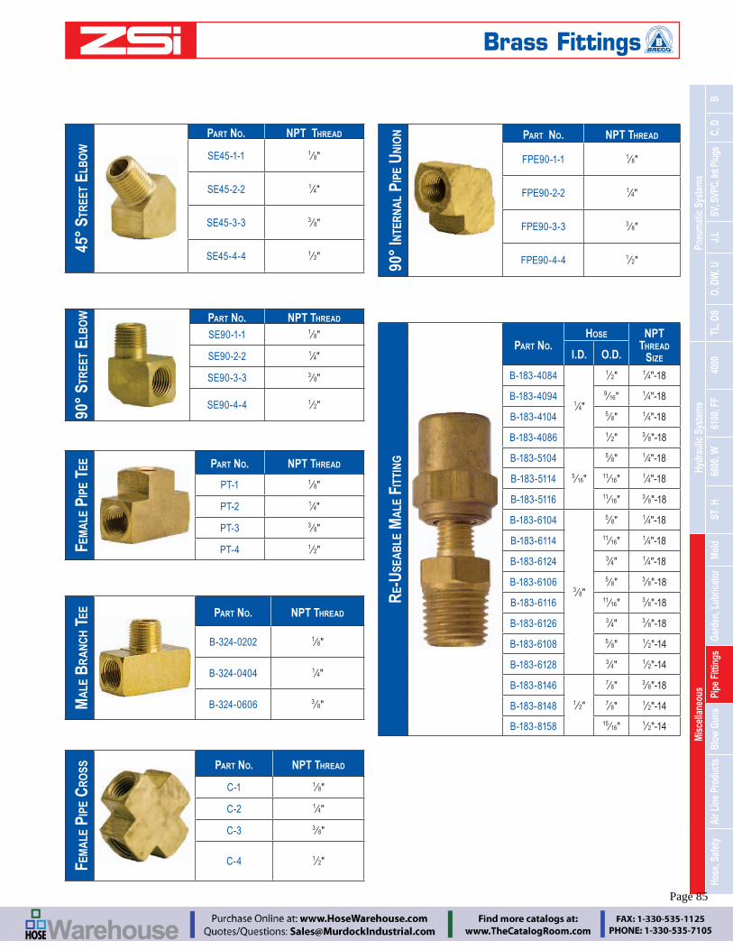
Mis
cella
neou
sHy
drau
lic S
yste
ms
Pneu
mat
ic S
yste
ms
Hose
, Saf
ety
Air L
ine
Prod
ucts
Blow
Gun
sPi
pe F
ittin
gsGa
rden
, Lub
ricat
orM
old
ST. H
6600
, W61
00, F
F40
00TL
, DS
O, D
W, U
J,L
SV, S
VPC,
Int P
lugs
C, D
B
Engineering Catalog www.zsi-inc.com – 85 –
90°
STR
EET
ELB
OW PART NO. NPT THREAD
SE90-1-1 18"
SE90-2-2 14"
SE90-3-3 38"
SE90-4-4 12"
45°
STR
EET
ELB
OW
PART NO. NPT THREAD
SE45-1-1 18"
SE45-2-2 14"
SE45-3-3 38"
SE45-4-4 12"
FEM
ALE
PIP
E TE
E PART NO. NPT THREAD
PT-1 18"
PT-2 14"
PT-3 38"
PT-4 12"
MA
LE B
RA
NC
H T
EE PART NO. NPT THREAD
B-324-0202 18"
B-324-0404 14"
B-324-0606 38"
FEM
ALE
PIP
E C
RO
SS PART NO. NPT THREAD
C-1 18"
C-2 14"
C-3 38"
C-4 12"
90°
INTE
RN
AL
PIPE
UN
ION PART NO. NPT THREAD
FPE90-1-1 18"
FPE90-2-2 14"
FPE90-3-3 38"
FPE90-4-4 12"
RE-
USE
AB
LE M
ALE
FIT
TIN
G
PART NO.HOSE NPT
THREAD SIZEI.D. O.D.
B-183-4084
14"
12" 1
4"-18
B-183-4094 916" 1
4"-18
B-183-4104 58" 1
4"-18
B-183-4086 12" 3
8"-18
B-183-5104
516"
58" 1
4"-18
B-183-5114 1116" 1
4"-18
B-183-5116 1116" 3
8"-18
B-183-6104
38"
58" 1
4"-18
B-183-6114 1116" 1
4"-18
B-183-6124 34" 1
4"-18
B-183-6106 58" 3
8"-18
B-183-6116 1116" 3
8"-18
B-183-6126 34" 3
8"-18
B-183-6108 58" 1
2"-14
B-183-6128 34" 1
2"-14
B-183-8146
12"
78" 3
8"-18
B-183-8148 78" 1
2"-14
B-183-8158 1516" 1
2"-14
Brass Fittings
Page 85

– 86 – www.zsi-inc.com
MA
LE R
EDU
CIN
G H
EX N
IPPL
E
PART NO.
NPTF THREAD
EXTERNAL
NPTF THREAD
EXTERNAL
B-379-0402 14" 1
8"
B-379-0602 38" 1
8"
B-379-0604 38" 1
4"
B-379-0806 12" 3
8"
MA
LE H
EX N
IPPL
E
PART NO. NPT THREAD
B-370-0202 18"
B-370-0404 14"
B-370-0606 38"
B-370-0808 12"
B-370-1212 34"
FEM
ALE
HEX
NIP
PLE
PART NO. NPT THREAD
B-371-0202 18"
B-371-0404 14"
B-371-0606 38"
B-371-0808 12"
FEM
AIL
E R
EDU
CER
BU
SHIN
G
PART NO.
NPT THREAD
EXTERNAL
NPTF THREAD INTERNAL
PRB-2-1 14" 1
8"
PRB-3-1 38" 1
8"
PRB-3-2 38" 1
4"
PRB-4-1 12" 1
8"
PRB-4-2 12" 1
4"
PRB-4-3 12" 3
8"
PRB-6-3 34" 3
8"
PRB-6-4 34" 1
2"
PRB-8-4 1 12"
PRB-8-6 1 34"
MA
LE -
FEM
ALE
ADA
PTER
PART NO.
NPT THREAD EXTERNAL
NPTF THREAD INTERNAL
AD-1-1 18" 1
8"
AD-1-2 18" 1
4"
AD-2-2 14" 1
4"
AD-2-3 14" 3
8"
AD-3-3 38" 3
8"
AD-3-4 38" 1
2"
AD-4-4 12" 1
2"
AD-4-6 12" 3
4"
AD-6-6 34" 3
4"
RED
UC
ING A
DAPT
ER
PART NO.
NPT THREAD INTERNAL
NPTF THREAD
INTERNAL
B-377-0402 18" 1
4"
B-377-0604 14" 3
8"
B-377-0806 38" 1
2"
CLO
SE N
IPPL
ES
PART NO. NPT THREAD
N-1 18"
N-2 14"
N-3 38"
N-4 12"
N-6 34"
HEX
HEA
D P
LUG
S
PART NO. NPT THREAD
SHP-1 18"
SHP-2 14"
SHP-3 38"
SHP-4 12"
Brass - Bushings, Adapters, Nipples
Page 86

Mis
cella
neou
sHy
drau
lic S
yste
ms
Pneu
mat
ic S
yste
ms
Hose
, Saf
ety
Air L
ine
Prod
ucts
Blow
Gun
sPi
pe F
ittin
gsGa
rden
, Lub
ricat
orM
old
ST. H
6600
, W61
00, F
F40
00TL
, DS
O, D
W, U
J,L
SV, S
VPC,
Int P
lugs
C, D
B
Engineering Catalog www.zsi-inc.com – 87 –
PIPE
CO
UPL
ING
PART NUMBER
FEMALE PIPE 1
FEMALE PIPE 2
B-5000-2 18" 1
8"B-5000-4-2 1
4" 18"
B-5000-4 14" 1
4"B-5000-6-2 3
8" 18"
B-5000-6-4 38" 1
4"B-5000-6-6 3
8" 38"
B-5000-8-4 12" 1
4"B-5000-8-6 1
2" 38"
B-5000-8 12" 1
2"
HEX
PIP
E N
IPPL
E
PART NUMBER
MALE PIPE 1
MALE PIPE 2
B-5404-2 18" 1
8"
B-5404-4-2 14" 1
8"
B-5404-4 14" 1
4"
B-5404-6 38" 3
8"
B-5404-8-4 12" 1
4"
B-5404-8-6 12" 3
8"
B-5404-8 12" 1
2"
MA
LE E
LBO
W
PART NUMBER
MALE PIPE 1
MALE PIPE 2
B-5500-2 18" 1
8"
B-5500-4-2 14" 1
8"
B-5500-4 14" 1
4"
B-5500-6-4 38" 1
4"
B-5500-6 38" 3
8"
B-5500-8-4 12" 1
4"
B-5500-8-6 12" 3
8"
B-5500-8 12" 1
2"
EXPA
ND
ING P
IPE
ADA
PTER
B-5
405
PART NUMBER
MALE PIPE 1
FEMALE PIPE 2
B-5405-2-4 18" 1
4"
B-5405-2-6 18" 3
8"
B-5405-2-8 18" 1
2"
B-5405-4-4 14" 1
4"
B-5405-4-6 14" 3
8"
B-5405-4-8 14" 1
2"
B-5405-4-12 14" 3
4"
B-5405-6-6 38" 3
8"
B-5405-6-8 38" 1
2"
B-5405-8-8 12" 1
2"
FEM
ALE
PIP
E TE
E
PART NUMBER
FEMALE PIPE CONNECTIONS
B-5605-2 18"
B-5605-4 14"
B-5605-6 38"
B-5605-8 12"
90°
STR
EET
ELB
OW
PART NUMBER
MALE PIPE 1
FEMALE PIPE 2
B-5502-2 18" 1
8"
B-5502-2-4 18" 1
4"
B-5502-2-6 18" 3
8"
B-5502-4-2 14" 1
8"
B-5502-4 14" 1
4"
B-5502-4-6 14" 3
8"
B-5502-6-4 38" 1
4"
B-5502-6 38" 3
8"
B-5502-6-8 38" 1
2"
B-5502-8-4 12" 1
4"
B-5502-8-6 12" 3
8"
B-5502-8-8 12" 1
2"
CLA
MPS
PART NO. SIZE
HOSE O.D.
B-1113 12" 1
4"
B-1315 916
516
B-1518 58" 3
8"
Steel Pipe Fittings
Page 87

– 88 – www.zsi-inc.com
Drain Cocks - Brass Fittings
The design of the drain cock uses metal-to-metal seal which requires only hand tightening to assure positive leak-proof performance.
External seal.
Materials: Brass bodies/steel handles except where noted.
Pressure:
Used With: Copper, aluminum, steel hose and plastic tubing where applicable.
Temperature
Conformance: Designed for automotive or industrial use. Not intended for natural gas, LPG, nuclear or aircraft application, except as noted.
MALE PIPE THREAD
PART NO.
18" DC-1
14" DC-2
38" DC-3
Drain Cocks, Swivel Fittings
Features:
Steel body (1 and 3 Aluminum body (1
300 PSIG inlet maximum
Swivel FittingsZero Pressure Connect and Disconnect Design
Standard SwivelNon-Marring
Single Swivel
Non-Marring Dual Swivel
BRECO Swivel Fittings improve maneuverability and ergonomics when using air tools and spray guns. Functioning like a universal
ideal for applications where non-marring and scratch reduction is needed.
NON-MARRING DUAL SWIVEL
PART NO. DESCRIPTION
190010A 3 ⁄8" FPT x 1 ⁄4" MPT190011A 3 ⁄8" FPT x 3 ⁄8" MPT190012 1 ⁄2" FPT x 1 ⁄2" MPT
NON-MARRING SINGLE SWIVEL
PART NO. DESCRIPTION
190040 3 ⁄8" FPT x 1
190041 3 ⁄8" FPT x 3 ⁄8" MPT190042 1
2" FPT x 1 2" MPT
STANDARD SWIVEL (WITHOUT PLASTIC COVERING)
PART NO. DESCRIPTION
190026A 14" FPT x 1 4"MPT
190029A 38" " FPT x 1 4" MPT
190027A 38" FPT x 3
8" MPT190028 1
2" FPT x 1 2" MPTWhen used with percussion tools, a minimum of 18" of hose between tool and swivel is required. Page 88

Mis
cella
neou
sHy
drau
lic S
yste
ms
Pneu
mat
ic S
yste
ms
Hose
, Saf
ety
Air L
ine
Prod
ucts
Blow
Gun
sPi
pe F
ittin
gsGa
rden
, Lub
ricat
orM
old
ST. H
6600
, W61
00, F
F40
00TL
, DS
O, D
W, U
J,L
SV, S
VPC,
Int P
lugs
C, D
B
Engineering Catalog www.zsi-inc.com – 89 –
GUNS ONLY, NO TIPS INCLUDED
GUN ONLY DESCRIPTION116482 Lever Action Gun Only- NO TIPS INCLUDED301804 Pistol Grip Gun Only - NO TIPS INCLUDED
BLOW GUNS AND TIPS
GUN
W/NOZZLE SHOWN
NOZZLE
ONLY DESCRIPTION
PERFORMANCE @100 PSIG
FLOW CFM
OUTLET BLOCKED
NOISE LEVEL DBA
BG21 LEVER GUN W/NOZZLE
BGN1 Standard nozzle for general
blowing and drying applications
17.5 20 89.5
BG2B5 LEVER GUN W/NOZZLE
BGNB5 Air Screen nozzle
reduces chip fly back
5 18 85
BG25 LEVER GUN W/NOZZLE
BGN5 High flow safety nozzle for general dusting and
chip removal
20 20 89BG45 PISTOL GUN W/NOZZLE
LEVER GUN W/NOZZLE
BGN6 Needle tip nozzle
for fine flow and for small holes
- -
LEVER GUN W/NOZZLE
BGN7 Rubber tipped nozzle for deli-cate surfaces and for blowing
out fluid lines
- -
BG2X3 LEVER GUN W/NOZZLE
BGX3
for extending reach15 21 85.5
BG2X6 LEVER GUN W/NOZZLE
BGX6
for extending reach
14.1 22 84
BG2X12 LEVER GUN W/NOZZLE BGX12
for extending reach
13.3 24 85.5BG4X12 PISTOL GUN W/NOZZLE
– BGN2 Flexible extension - - -
– BGN3 Flexible extension - - -
BG-CPLR LEVER GUN W/NOZZLE
BGADP Quick change nozzle adapter
- - -
* WARNING: To be OSHA compliant, non-relieving nozzles may only be used when the blowgun’s inlet pressure is regulated to 30 PSI maximum.
BG-CPLR SHOWN W/OPTIONAL
QUICK CHANGE ADAPTER
BRECO BG Series Blowguns combine durability, performance,
Features:
Lever activation
10 different nozzle choices
Blow gun kit provides versatility
Quick-disconnect nozzle adapter
14" NPT inlet
OSHA Compliant* @ Max 150 PSI inlet PressureCompliant @ Max 150 PSI inl
BG45
*WARNING: To be OSHA compliant, non-relieving nozzles may only be used when the blowgun’s inlet pressure is regulated to 30 PSI maximum.
Pistol grip blow guns are ergonomically designed for operator comfort and safety.
Features:
Lightweight nylon body insulates from refrigerated air
Machined brass valve, nozzle & hose inlet for strength
Lever style trigger with comfortable grip for variable air
14" NPT female inlet
125 PSIG inlet maximum
and 1910.95 noise level @ Max 150 PSI inlet Pressure
PART NO. DESCRIPTIONFLOW (CFM) @ 100 PSIG
BG45Pistol Grip Gun with BGN5
20.0
BG4X12 Pistol Grip Gun with BGX12 13.3301804 Pistol Grip Gun Only –
Other BG Series nozzles and extensions may also be used with this blow gun.
BG Series Blow Guns & Tips
Page 89

– 90 – www.zsi-inc.com
BGX6
BGADP(Patented Quick-Disconnect Nozzle Adapter)
BGN6
BGN5
BGN7 BGNB5
BG-CPLR(116482 Gun with BGADP Quick-Disconnect Nozzle Adapter shown)
Blow Gun Kit
popular nozzles for industrial and automotive uses. This kit includes a high quality, lever-operated heavy-duty blow gun featuring a patented quick dis-connect nozzle adapter which allows users to switch
safety nozzle, six inch extension safety nozzle, rubber tip nozzle, needle tip nozzle, and air-screen safety nozzle. For handy storage, a clear vinyl compartmented snap pouch is included. Ideally suited as a counter sale product. To Order Complete Kit Use Part Number - BGQKIT
Air Chucks
Three BRECO Air Chucks are available: a right angle heavy-duty air chuck, a heavy duty straight body air chuck, and a dual air
14" FPT
inlets.
PART NO. DESCRIPTION
AC40 Right Angle Air Chuck, 1
AC42 Dual Air ChuckAC45 Straight Body Air Chuck, 1
Dual Air Chuck
Straight Body Air ChuckRight Angle
Air Chuck
N7
BG
BGX6BGX6
BGN6
BGX6
Air Line Products
The BRECO Blow gun provides greater force for chip removal with less air consumption...saving energy without loss of performance. The features of this low cost blow gun offer top performance for any application.
Easy Operation: Thumb lever operation allows operator to have maximum control. Hooked shaped body for convenient stor-
tip prevents pressure buildup above 29 PSIG if nozzle is obstructed.
Inlet Sizes: 14" NPT
Temp. Range:
Inlet Pressure:
Regulated Pressure:
Weight: 2.07 oz.
Caution:air, nor in applications which may exceed maximum recommended operating conditions.
Safety Blow Gun B-8003
Page 90

Mis
cella
neou
sHy
drau
lic S
yste
ms
Pneu
mat
ic S
yste
ms
Hose
, Saf
ety
Air L
ine
Prod
ucts
Blow
Gun
sPi
pe F
ittin
gsGa
rden
, Lub
ricat
orM
old
ST. H
6600
, W61
00, F
F40
00TL
, DS
O, D
W, U
J,L
SV, S
VPC,
Int P
lugs
C, D
B
Engineering Catalog www.zsi-inc.com – 91 –
Free swivel under pressure eliminates hose twist
3-WAY Hose Manifold
3-WAY Hose Manifold with Sockets and Swivel Plugs
PART NO. DESCRIPTION INLET OUTLET
301787.01
3-Way Manifold
1 4" 14"
301805 38" 1
4"
301820 12" 3
8"6124-A 3-Way Flat Manifold 1
4" 14"
PART NO. DESCRIPTION INLET OUTLET
MAN2525A 3-Way Manifold with three D341 Sockets
14" FPT Sockets 1 4"
Industrial Interchange
MAN3825A 3-Way Manifold with three D341 Sockets
3 ⁄8" FPT; Sockets 1 4" Industrial Interchange
MAN5038A 3-Way Manifold with three D461 Sockets
12" FPT Sockets 3 8"
Industrial Interchange
6124 Flat Manifold w/ 3 sockets 14" plug 1
4" sockets
MF-2 Manifold w/ 3 sockets & 14" plug 1
4" sockets
MF-3 Manifold w/ 3 sockets & 3 8" plug 38" sockets
PART NO. DESCRIPTION INLET OUTLET
MAN2525S*
3-Way Manifold with three
Swivel Plugs
14" FPT Swivel Plug 1
4" Industrial Interchange
MAN3825S* 38" FPT Swivel Plug 1
4" Industrial Interchange
MAN5038S* 12" FPT; Swivel Plug 3
8" Industrial Interchange
* Note: Swivel Plugs are OPEN. Connection is needed to avoid leak path.
Add versatility to your compressed air systems and simplify multiple tool operations. The BRECO 3-Way Hose Manifolds allow three work stations to use the same air supply. Featuring a port design to maxi-
similar products on the market. Each manifold accepts three quick couplers or outlet hoses. Manifold has female NPT inlet and three female NPT outlets. Manifolds are available in three different inlet/outlet sizes.
An expanded style of our 3-Way Hose Manifold is available pre-assembled with a choice of three D Series manual sockets or three swivel plugs. This operational versatility allows three independent work stations to function with the same air supply. The port design
Free swiveliminate3-Way Manifold Shown
3-Way Flat Manifold
3-Way Manifold
Hose Manifolds
Page 91

– 92 – www.zsi-inc.com
-ting End Pre-Installed with Thread Compound 15’ and 25’ Lengths
BRECO Polyurethane Recoil Hose has greater durability than other types of hose due to exceptional wear characteris-tics. Polyurethane Recoil Hose is kink resistant and has exceptional memory characteristics due to elastic properties of
accessories. The BRECO Polyurethane Recoil Hose products are pre-bagged for convenience. Ideally suited as counter sale products.
PART NO. I.D. X O.D. LENGTH MPT FITTINGS
DCPOLY15 1 ⁄4" x 3 ⁄8" 15' 1 ⁄4" Rigid x 1 ⁄4" Swivel
DCPOLY25 1 ⁄4" x 3 ⁄8" 25' 1 ⁄4" Rigid x 1 ⁄4" Swivel
DCPOLY15ASSY 1 ⁄4" x 3 ⁄8" 15' DW340A Universal Socket x 1 ⁄4" Swivel
DCPOLY25ASSY 1 ⁄4" x 3 ⁄8" 25' DW340A Universal Socket x 1 ⁄4" Swivel
Features:
Greater durability than other recoil hoses due to exceptional wear characteristics
Longer life expectancy due to kink resistant properties
Superior recoil memory due to elastic properties
Pre-assembled and ready to use
Construction: Yellow polyurethane recoil hose with
Working Pressure: 170 PSIG @ 75F
Working Length: 80-90% of hose length DCPOLY15
DCPOLY15ASSY
DW340AUNIVERSALSwivel Fitting
Polyurethane Recoil Hose
Page 92

Mis
cella
neou
sHy
drau
lic S
yste
ms
Pneu
mat
ic S
yste
ms
Hose
, Saf
ety
Air L
ine
Prod
ucts
Blow
Gun
sPi
pe F
ittin
gsGa
rden
, Lub
ricat
orM
old
ST. H
6600
, W61
00, F
F40
00TL
, DS
O, D
W, U
J,L
SV, S
VPC,
Int P
lugs
C, D
B
Engineering Catalog www.zsi-inc.com – 93 –
Pressurized lines employing quick-disconnect couplers should be considered potentially hazardous and must be used with safety in mind. Proper selection and use of appropriate couplers will help you maintain a safe working environment for personnel, equipment, and products.
BRECO quick-disconnect couplers are precision devices—do not modify, strike, or otherwise abuse the coupling halves. Never exceed the pressure or temperature limits and always protect the hose and coupler assembly from moving equipment.
Be cautious when moving pressurized hoses as some types of quick-disconnect couplers may unintentionally disconnect if the coupler
Safety Vent Couplers
BRECO Safety Vent couplers are designed to minimize the pos-sibility of inadvertent disconnection and potentially hazardous hose whip. BRECO SV and SVPC Series Safety Vent couplers are "zero pressure" connect/disconnect type couplers designed to safely vent downstream pressure prior to disengaging the plug.
BRECO SVPC and SV Series Safety Vent Couplers
Safety Vent couplers are nearly effortless to connect and great for hose use. They are also especially useful for single-hand operation when they are mounted to hard lines such as an overhead air drop. Once inserted into the SV socket, the plug is lightly gripped and will stay in place allowing the operator to use the same hand to slide the sleeve straight forward to the "on" position. As the sleeve is being moved to the "on" position, the SV socket will securely lock the plug
SV Series sockets can also be used as a 3-way valve to turn off the
the plug. By turning and sliding the sleeve to the "exhaust" position, downstream air pressure is relieved but the plug remains locked in place. Turning and sliding the sleeve in the opposite direction allows
BRECO SV Series couplers are the ultimate solution to accidental disconnect hose whip dangers.
BRECO SVPC Series Safety Vent Couplers
The SVPC Series Safety Vent couplers provide the same safety vent features as the SV Series, and are plastic encapsulated to prevent
-
We strongly recommend that the end user obtain proper training before using quick-disconnect couplers, air blowguns, and other BRECO products. Thoughtful analysis of the user’s needs and application must be given before selecting a product.
Our dedicated employees and distributors are eager to explain the features, benefits, and proper selection of BRECO products,
and answer your questions regarding their correct application and safe use.
encounters an obstacle as the hose is dragged. The pressurized media subsequently escaping from the freed line can force the hose assembly to violently whip about, possibly causing personal injury, equipment/product damage, and economic loss. BRECO Safety Vent couplers and plugs, designed to minimize hose whip hazards, should be used wherever the risk is present. Personnel must be instructed
disconnecting pressurized lines.
Above all, always wear appropriate personal protection equipment and safety glasses when working with, or near, pressurized lines utilizing quick-disconnect couplers.
ries sockets will prevent plug release until the downstream line pres-sure is vented to atmosphere and the plug can be safely removed.
Ball-Lock Option
-tion and is available on BRECO D Series and DM Series sockets. Couplers with the BL designation are constructed with sleeves hav-ing a slot that must be aligned with a ball or pin before the sleeve is allowed to retract. Rotating the sleeve 180 degrees so the slot is not aligned with the ball or pin will minimize the chance of accidental sleeve retraction.
Ball Check Plugs
Ball check plugs are offered in several sizes of Industrial Interchange
a check valve when the plug is disconnected from the coupler. The check valve action minimizes hose whip by causing the pressurized gas to escape slowly from the disconnected hose.
Air Blowguns
-tion, and other operations. The blowguns are available with zinc or nylon bodies with a variety of optional nozzles for nearly any use.
compliant models to suit your particular needs.
Blow Guns and nozzles that comply with OSHA regulations will limit the pressure of air exiting the nozzle to less than 30 PSIG when the nozzle is dead-headed.
(*) Note: If a non-OSHA compliant blow gun nozzle (BGN6, or BGN7) is used, air pressure to the gun’s inlet must be regulated to less than 30 PSIG to meet OSHA regulations.
Think Safety First
Page 93

– 94 – www.zsi-inc.com
5100-S2-12B B-6105-12
5100-S2-16B B-6105-16
5100-S2-20B B-6105-20
5100-S2-24B B-6105-24
5100-S5-12B B-6125-12
5100-S5-12B B-6115-12
5100-S5-16B B-6125-16
5100-S5-16B B-6115-16
5100-S5-20B B-6125-20
5100-S5-20B B-6115-20
5100-S5-24B B-6125-24
5100-S5-24B B-6115-24
5101-12B B-6100-12
5101-12B B-6120-12
5101-16B B-6100-16
5101-16B B-6120-16
5101-20B B-6100-20
5101-20B B-6120-20
5101-24B B-6100-24
5101-24B B-6120-24
5110-S5-12B B-6135-12
5110-S5-16B B-6135-16
5110-S5-20B B-6135-20
5110-S5-24B B-6135-24
5601-12-10S B-6601-12-10
5601-12-12S B-6601-12-12
5601-16-16S B-6601-16-16
5601-2-4S B-6601-2-4
5601-4-4S B-6601-4-4
5601-6-6S B-6601-6-6
5601-8-10S B-6601-8-10
5602-12-10S B-6602-12-10
5602-12-12S B-6602-12-12
5602-16-16S B-6602-16-16
5602-2-4S B-6602-2-4
5602-4-4S B-6602-4-4
5602-6-6S B-6602-6-6
5602-8-10S B-6602-8-10
5608-12-10S B-6608-12-10
5608-12-12S B-6608-12-12
5608-16-16s B-6608-16-16
5608-8-10S B-6608-8-10
5610-10-10S B-6610-10-10
5610-12-10S B-6610-12-10
5610-12-12S B-6610-12-12
5610-16-16a B-6610-16-16
5610-8-10S B-6610-8-10
5657-10 B-6657-10
5657-12 B-6657-12
5657-16 B-6657-16
5657-4 B-6657-4
5657-6 B-6657-6
5659-10 B-6659-10
5659-12 B-6659-12
5659-16 B-6659-16
5659-4 B-6659-4
5659-6 B-6659-6
FD40-1000-02-04 B-2BF1-B
FD40-1000-04-04 B-2BF2-B
FD40-1000-04-06 B-3BF2-B
FD40-1000-06-04 B-2BF3-B
FD40-1000-06-06 B-3BF3-B
FD40-1000-08-06 B-3BF4-B
FD40-1000-08-08 B-4BF4-B
FD40-1001-02-04 B-2BM1-B
FD40-1001-04-04 B-2BM2-B
FD40-1001-04-06 B-3BM2-B
FD40-1001-06-04 B-2BM3-B
FD40-1001-06-06 B-3BM3-B
FD40-1001-08-06 B-3BM4-B
FD40-1001-08-08 B-4BM4-B
FD40-1013-02-04 B-B2F1-S
FD40-1013-04-04 B-B2F2-S
FD40-1013-06-04 B-B2F3-S
FD40-1013-06-06 B-B3F3-S
FD40-1013-08-06 B-B3F4-S
FD40-1013-08-08 B-B4F4-S
FD40-1014-02-04 B-B2M1-S
FD40-1014-04-04 B-B2M2-S
FD40-1014-04-06 B-B3M2-S
FD40-1014-06-04 B-B2M3-S
FD40-1014-06-06 B-B3M3-S
FD40-1014-06-08 B-B4M3-S
FD40-1014-08-06 B-B3M4-S
FD40-1014-08-08 B-B4M4-S
FD40-1016-04-04 B-B2PS2-S
FD40-1016-06-06 B-B3PS3-S
FD40-1016-08-08 B-B4PS4-S
FD40-1019-04-04 B-B2S2-S
FD40-1019-06-06 B-B3S3-S
FD40-1019-08-08 B-B4S4-S
FD41-1000-04-04 B-2OF2-B
FD41-1000-06-04 B-2OF3-B
FD41-1013-04-04 B-O2F2-S
FD41-1014-04-04 B-O2M2-S
FD42-1001-04-04 B-4050-2P
FD42-1002-04-04 B-4010-2P
FD43-1001-02-04 B-2CF1-B
FD43-1001-02-04 D320
FD43-1001-04-04 B-2CF2-B
FD43-1001-04-04 D340
FD43-1001-04-06 B-3CF2-S
FD43-1001-04-06 D440
FD43-1001-06-04 B-2CF3-B
FD43-1001-06-04 D360
FD43-1001-06-06 B-3CF3-S
FD43-1001-06-06 D460
FD43-1011-02-04 B-2CM1-B
FD43-1011-02-04 D321
FD43-1011-04-04 B-2CM2-B
FD43-1011-04-04 D341
FD43-1011-04-06 B-3CM2-S
FD43-1011-04-06 D441
FD43-1011-06-04 B-2CM3-B
FD43-1011-06-04 D361
FD43-1011-06-06 B-3CM3-S
FD43-1011-06-06 D461
FD43-1011-08-06 B-3CM4-S
FD43-1011-08-06 D481
FD43-1011-08-08 B-4CM4-S
FD43-1011-08-08 D581
FD43-1013-08-06 B-3CF4-S
FD43-1013-08-08 B-4CF4-S
FD43-1013-08-08 D580
FD43-1031-04-04 B-2CPS2-B
FD43-1031-04-04 D344
FD43-1031-06-04 B-2CPS3-B
FD43-1031-06-04 D364
FD45-1002-02-02 DS1F1-S
FD45-1002-04-04 DS2F2-S
FD45-1002-06-06 DS3F3-S
FD45-1002-08-10 DS4F4-S
FD45-1002-12-12 DS6F6-S
FD45-1002-16-16 DS8F8-S
FD45-1003-02-02 1DSF1-S
FD45-1003-04-04 2DSF2-S
FD45-1003-06-06 3DSF3-S
FD45-1003-08-10 4DSF4-S
FD45-1003-12-12 6DSF6-S
FD45-1003-16-16 8DSF8-S
FD45-1004-04-04 DS2F2-SS
FD45-1004-06-06 DS3F3-SS
FD45-1004-08-10 DS4F4-SS
FD45-1004-12-12 DS6F6-SS
FD45-1004-16-16 DS8F8-SS
FD45-1005-04-04 2DSF2-SS
FD45-1005-06-06 3DSF3-SS
FD45-1005-08-10 4DSF4-SS
FD45-1005-12-12 6DSF6-SS
FD45-1005-16-16 8DSF8-SS
FD45-1040-02 BH1-66M
FD45-1040-04 BH2-66M
FD45-1040-06 BH3-66M
FD45-1040-10 BH4-66M
FD45-1040-12 BH6-66M
FD45-1040-16 BH8-66M
FD45-1041-02 BH1-65M
FD45-1041-04 BH2-65M
FD45-1041-06 BH3-65M
FD45-1041-10 BH4-65M
FD45-1041-12 BH6-65M
FD45-1041-16 BH8-65M
FD45-1046-04-04 DS2F2-BI
FD45-1086-02-02 DS1F1-B
FD45-1086-04-04 DS2F2-B
FD45-1086-06-06 DS3F3-B
FD45-1086-08-10 DS4F4-B
FD45-1086-12-12 DS6F6-B
FD45-1086-16-16 DS8F8-B
FD45-1101-02-02 1DSF1-B
FD45-1101-04-04 2DSF2-B
FD45-1101-06-06 3DSF3-B
FD45-1101-08-10 4DSF4-B
FD45-1101-12-12 6DSF6-B
FD45-1101-16-16 8DSF8-B
FD45-1206-04-04 2DSF2-BI
FD89-1001-06-06 B-3FF3-FP
FD89-1001-08-08 B-3FF4-FP
FD89-1001-08-08 B-4FF4-FP
FD89-1001-12-08 B-4FF6-FP
FD89-1001-12-12 B-6FF6-FP
FD89-1002-06-06 B-FF3F3-FP
FD89-1002-08-08 B-FF3F4-FP
FD89-1002-08-08 B-FF4F4-FP
FD89-1002-12-08 B-FF4F6-FP
FD89-1002-12-12 B-FF6F6-FP
Aeroquip to BRECO Interchange
Interchangeability Charts
Note: Interchange is based on best available information. We cannot guarantee the accuracy and recommend confirmation of detailed specifications prior to ordering.Page 94

Inde
xTe
chni
cal D
ata
BREC
O In
dust
rial I
nter
chan
ge
Engineering Catalog www.zsi-inc.com – 95 –
C10 B-4CF4-S
C10 D580
C10-23 B-4CF3-S
C10-23 D560
C10-45 B-4CS4-S
C10-45 D582
C1B B-2JM2-B
C2-23B B-2JF3-B
C2-42B B-2JS2-B
C20-23B B-2CF3-B
C20-23B D360
C20-42B B-2CS2-B
C20-42B D342
C20-44B B-2CS3-B
C20-44B D362
C20B B-2CF2-B
C20B D340
C21-03B B-2CM3-B
C21-03B D361
C21B B-2CM2-B
C21B D341
C25 B-3CM3-S
C25-02 B-3CM2-S
C25-02 D441
C25-04 B-3CM4-S
C26 B-3CF3-S
C26 D460
C26-22 B-3CF2-S
C26-22 D440
C26-24 B-3CF4-S
C26-24 D480
C26-44 B-3CS3-S
C26-44 D462
C26-44L B-3CPS3-S
C26-44L D464
C26-45 B-3CS4-S
C26-45 D482
C28 B-2LF2-B
C2B B-2JF2-B
C35 B-3OM3-S
C36 B-3OF3-S
C45 B-2OM2-S
C46 B-2OF2-S
C5 B-3JM3-S
C5-04 B-3JM4-S
C6 B-3JF3-S
C6-24 B-3JF4-S
C6-44 B-3JS3-S
C6-44L B-3JPS3-S
C6-45 B-3JS4-S
C60 B-2UF2-B
C60 DW340A
C61 B-2UM2-B
C61 DW341A
C7 B-3JM2-S
C8 B-3JF2-S
C9 B-4CM4-S
C9 D581
C9-03 B-4CM3-S
C9-03 D561
CP1 B-J2M2-S
CP1-03 B-J2M3-S
CP1-42 B-J2S2-S
CP1-42L B-J2PS2-S
CP1-44 B-J2S3-S
CP1-44L B-J2PS3-S
CP17 B-B4M4-S
CP17-03 B-B4M3-S
CP17-45 B-B4S4-S
CP18 B-B4F4-S
CP18-23 B-B4F3-S
CP1B B-J2M2-B
CP2 B-J2F2-S
CP2-23 B-J2F3-S
CP20 B-B2F2-S
CP20-23 B-B2F3-S
CP20B B-B2F2-B
CP21 B-B2M2-S
CP21-03 B-B2M3-S
CP21-42 B-B2S2-S
CP21-42L B-B2PS2-S
CP21-44 B-B2S3-S
CP21-44L B-B2PS3-S
CP21B B-B2M2-B
CP25 B-B3M3-S
CP25-02 B-B3M2-S
CP25-04 B-B3M4-S
CP25-42L B-B3PS2-S
CP25-44 B-B3S3-S
CP25-44L B-B3PS3-S
CP25-45 B-B3S4-S
CP26 B-B3F3-S
CP26-22 B-B3F2-S
CP26-24 B-B3F4-S
CP27 B-L2M2-S
CP28 B-L2F2-S
CP2B B-J2F2-B
CP35 B-O3M3-S
CP36 B-O3F3-S
CP37 B-O2M2-S
CP38 B-O2F2-S
CP5 B-J3M3-S
CP5-44 B-J3S3-S
CP5-44L B-J3PS3-S
CP6 B-J3F3-S
CP7 B-J3M2-S
CP8 B-J3F2-S
CPST1 ST1M1-S
CPST1B ST1M1-B
CPST2 ST1F1-S
CPST2B ST1F1-B
CPST3 ST2M2-S
CPST3B ST2M2-B
CPST4 ST2F2-S
CPST4B ST2F2-B
CPST5 ST3M3-S
CPST5B ST3M3-B
CPST6 ST3F3-S
CPST6B ST3F3-B
CPST7 ST4M4-S
CPST8 ST4F4-S
CST1B 1STM1-B
CST2B 1STF1-B
CST3B 2STM2-B
CST4B 2STF2-B
CST5B 3STM3-B
CST6B 3STF3-B
CST7B 4STM4-B
CST8B 4STF4-B
Amflo to BRECO Interchange
Interchangeability Charts
Note: Interchange is based on best available information. We cannot guarantee the accuracy and recommend confirmation of detailed specifications prior to ordering.Page 95

– 96 – www.zsi-inc.com
1101STB ST2M2-B1101STS ST2M2-S1102STB ST2F2-B1102STS ST2F2-S1103STB ST3M3-B1103STS ST3M3-S1105STB ST3F3-B1105STS ST3F3-S1109STB ST4M4-B1109STS ST4M4-S
110ST 2STF2-B1110STB ST4F4-B1110STS ST4F4-S
111ST 3STF3-B112ST 2STM2-B115ST 3STM3-B117ST 4STF4-B119ST 4STM4-B
120 B-4CF4-S120 D5801201 B-B4M4-S1202 B-B4F4-S1203 B-B4M3-S1204 B-B4F3-S1207 B-B4S3-S1208 B-B4S4-S120A B-4BF4-B121 B-4CM3-S121 D561
121A B-4BM3-B122 B-4CM4-S122 D581
122A B-4BM4-B123 B-4CF3-S123 D560
123A B-4BF3-B127 B-4CS3-S127 D562128 B-4CS4-S128 D582
128A B-4BS4-B128A B-3BS4-B
128AL B-4BPS4-B140 B-2OF2-B1401 B-O2M2-S1402 B-O2F2-S1403 B-O2M3-S1404 B-O2M1-S1405 B-O2F3-S1406 B-O2S2-S141 B-2OF3-B142 B-2OM2-B143 B-2OS2-B145 B-2OM3-B150 B-2CF2-B150 D3401501 B-B2M2-S
1501-B B-B2M2-B1502 B-B2F2-S
1502B B-B2F2-B1503 B-B2M3-S1504 B-B2M1-S1505 B-B2F3-S
1506 B-B2S2-S1506L B-B2PS2-S1508 B-B2S3-S
1508L B-B2PS3-S1509 B-B2F1-S150A B-2BF2-B150U B-2UF2-B150U DW340A151 B-2CF3-B151 D360
151A B-2BF3-B152 B-2CM2-B152 D341
152A B-2BM2-B152U B-2UM2-B152U DW341A153 B-2CS2-B153 D342
153A B-2BS2-B153AL B-2BPS2-B153L B-2CPS2-B153L D344155 B-2CM3-B155 D361
155A B-2BM3-B156 B-2CS3-B156 D362
156A B-2BS3-B156AL B-2BPS3-B156L B-2CPS3-B156L D364158 B-2CF1-B158 D320
158A B-2BF1-B159 B-2CM1-B159 D321
159A B-2BM1-B160 B-2JF2-B1601 B-J2M2-S
1601B B-J2M2-B1602 B-J2F2-S
1602B B-J2F2-B1603 B-J2M3-S1604 B-J2M1-S1605 B-J2F3-S1606 B-J2S2-S
1606L B-J2PS2-S1608 B-J2S3-S
1608L B-J2PS3-S161 B-2JF3-B162 B-2JM2-B163 B-2JS2-B
163L B-2JPS2-B165 B-2JM3-B166 B-2JS3-B
166L B-2JPS3-B170 B-2LF2-B1701 B-L2M2-S1702 B-L2F2-S3401 B-B6M6-S3402 B-B6F6-S340A B-6BF6-B342A B-6BM6-B
343A B-6BS6-B580 B-3CF3-S580 D4605801 B-B3M3-S5802 B-B3F3-S5803 B-B3M2-S5804 B-B3F2-S5805 B-B3F4-S5806 B-B3S3-S
5806L B-B3PS3-S5808 B-B3S4-S5809 B-B3M4-S580A B-3BF3-B581 B-3CM3-S
581A B-3BM3-B582 B-3CF2-S582 D440
582A B-3BF2-B583 B-3CM2-S583 D441
583A B-3BM2-B584 B-3CF4-S584 D480
584A B-3BF4-B586 B-3CS3-S586 D462
586A B-3BS3-B586AL B-3BPS3-B586L B-3CPS3-S586L D464587 B-3CM4-S
587A B-3BM4-B588 B-3CS4-S588 D482590 B-3JF3-S5901 B-J3M3-S5902 B-J3F3-S5903 B-J3M2-S5904 B-J3F2-S5906 B-J3S3-S
5906L B-J3PS3-S591 B-3JM3-S592 B-3JF2-S593 B-3JM2-S598 B-3JS3-S
598L B-3JPS3-S
Coilhose to BRECO Interchange
Interchangeability Charts
Note: Interchange is based on best available information. We cannot guarantee the accuracy and recommend confirmation of detailed specifications prior to ordering.Page 96

Inde
xTe
chni
cal D
ata
BREC
O In
dust
rial I
nter
chan
ge
Engineering Catalog www.zsi-inc.com – 97 –
16-263 2DSF2-S
16-363 3DSF3-S
16-463 4DSF4-S
16-663 6DSF6-S
16-863 8DSF8-S
17-263 DS2F2-S
17-363 DS3F3-S
17-463 DS4F4-S
17-663 DS6F6-S
17-863 DS8F8-S
18-300 B-4050-3
18-400 B-4050-4
18-415 B-4050-15
18-600 B-4050-5
18-660 B-4150-5
18-800 B-4050-6
19-300 B-4010-3
19-400 B-8010-4
19-415 B-8010-15
19-600 B-8010-5
19-660 B-4110-5
19-800 B-4010-6
30-200 B-2WM2-S
30-300 B-3WM3-S
30-300F B-3WF3-S
31-200 B-W2F2-S
31-300 B-W3F3-S
3HTF3 B-3FF3-FP
3HTF4 B-3FF4-FP
4HTF4 B-4FF4-FP
4HTF6 B-4FF6-FP
56-100 B-6601-2-4
56-200 B-6601-4-4
56-300 B-6601-6-6
56-400 B-6601-8-10
56-600 B-6601-12-10
56-660 B-6601-12-12
56-800 B-6601-16-16
57-100 B-6602-2-4
57-200 B-6602-4-4
57-300 B-6602-6-6
57-400 B-6602-8-10
57-600 B-6602-12-10
57-660 B-6602-12-12
57-800 B-6602-16-16
6HTF6 B-6FF6-FP
78-1000 B-6125-20
78-1200 B-6125-24
78-600 B-6125-12
78-800 B-6125-16
79-1000 B-6105-20
79-1200 B-6105-24
79-600 B-6105-12
79-800 B-6105-16
8HTF8 B-8FF8-FP
B16-263 2DSF2-B
B16-363 3DSF3-B
B16-463 4DSF4-B
B16-663 6DSF6-B
B16-863 8DSF8-B
B17-263 DS2F2-B
B17-363 DS3F3-B
B17-463 DS4F4-B
B17-663 DS6F6-B
B17-863 DS8F8-B
DC1 B-2JM2-B
DC10 B-4CF4-S
DC10 D580
DC1023 B-4CF3-S
DC1023 D560
DC103 B-2JM3-B
DC1044 B-4CS3-S
DC1044 D562
DC1045 B-4CS4-S
DC1045 D582
DC1046 B-4CS6-S
DC1046 D5122
DC2 B-2JF2-B
DC20 B-2CF2-B
DC20 D340
DC2021 B-2CF1-B
DC2021 D320
DC2023 B-2CF3-B
DC2023 D360
DC2042 B-2CS2-B
DC2042 D342
DC2042L B-2CPS2-B
DC2042L D344
DC2044 B-2CS3-B
DC2044 D362
DC2044L B-2CPS3-B
DC2044L D364
DC20S B-2CF2-SS
DC21 B-2CM2-B
DC21 D341
DC2101 B-2CM1-B
DC2101 D321
DC2103 B-2CM3-B
DC2103 D361
DC21S B-2CM2-SS
DC221 B-2JF1-B
DC223 B-2JF3-B
DC242 B-2JS2-B
DC242L B-2JPS2-B
DC244 B-2JS3-B
DC244L B-2JPS3-B
DC25 B-3CM3-S
DC2502 B-3CM2-S
DC2502 D441
DC2504 B-3CM4-S
DC26 B-3CF3-S
DC26 D460
DC2622 B-3CF2-S
DC2622 D440
DC2624 B-3CF4-S
DC2624 D480
DC2644 B-3CS3-S
DC2644 D462
DC2644L B-3CPS3-S
DC2644L D464
DC2645 B-3CS4-S
DC2645 D482
DC28 B-2LF2-B
DC35 B-3OM3-S
DC36 B-3OF3-S
DC37 B-2OM2-B
DC3703 B-2OM3-B
DC38 B-2OF2-B
DC3823 B-2OF3-B
DC3842 B-2OS2-B
DC3842L B-2OPS2-B
DC3844 B-2OS3-B
DC3844L B-2OPS3-B
DC5 B-3JM3-S
DC504 B-3JM4-S
DC6 B-3JF3-S
DC624 B-3JF4-S
DC644 B-3JS3-S
DC644L B-3JPS3-S
DC645 B-3JS4-S
DC7 B-3JM2-S
DC7024 B-6BF4-B
DC7028 B-6BF6-B
DC7028 B-6BF8-B
DC7045 B-6BS4-B
DC7046 B-6BS6-B
DC7048 B-6BS8-B
DC7104 B-6BM4-B
DC7106 B-6BM6-B
DC7108 B-6BM8-B
DC8 B-3JF2-S
DC9 B-4CM4-S
DC9 D581
DC903 B-4CM3-S
DC903 D561
DCB10 B-4BF4-B
DCB1023 B-4BF3-B
DCB1026 B-4BF6-B
DCB1044 B-4BS3-B
DCB1045 B-4BS4-B
DCB1046 B-4BS6-B
DCB20 B-2BF2-B
DCB2023 B-2BF3-B
DCB2042 B-2BS2-B
DCB2044 B-2BS3-B
DCB21 B-2BM2-B
DCB2103 B-2BM3-B
DCB25 B-3BM3-B
DCB2502 B-3BM2-B
DCB2504 B-3BM4-B
DCB26 B-3BF3-B
DCB2622 B-3BF2-B
DCB2624 B-3BF4-B
DCB2644 B-3BS3-B
DCB2645 B-3BS4-B
DCB9 B-4BM4-B
DCB903 B-4BM3-B
DCB906 B-4BM6-B
DCP1 B-J2M2-S
DCP101 B-J2M1-S
DCP103 B-J2M3-S
DCP142 B-J2S2-S
DCP142L B-J2PS2-S
DCP144 B-J2S3-S
DCP144L B-J2PS3-S
DCP17 B-B4M4-S
DCP1703 B-B4M3-S
DCP1706 B-B4M6-S
DCP1744 B-B4S3-S
DCP1745 B-B4S4-S
DCP1746 B-B4S6-S
DCP18 B-B4F4-S
Dixon to BRECO Interchange [PAGE 1 OF 2]
Interchangeability Charts
Note: Interchange is based on best available information. We cannot guarantee the accuracy and recommend confirmation of detailed specifications prior to ordering.Page 97

– 98 – www.zsi-inc.com
Interchangeability Charts
DCP1823 B-B4F3-S
DCP1826 B-B4F6-S
DCP2 B-J2F2-S
DCP20 B-B2F2-S
DCP2021 B-B2F1-S
DCP2023 B-B2F3-S
DCP20B B-B2F2-B
DCP20S B-B2F2-SS
DCP21 B-B2M2-S
DCP2101 B-B2M1-S
DCP2103 B-B2M3-S
DCP2142 B-B2S2-S
DCP2142L B-B2PS2-S
DCP2144 B-B2S3-S
DCP2144L B-B2PS3-S
DCP21B B-B2M2-B
DCP21S B-B2M2-SS
DCP221 B-J2F1-S
DCP223 B-J2F3-S
DCP25 B-B3M3-S
DCP2502 B-B3M2-S
DCP2504 B-B3M4-S
DCP2542L B-B3PS2-S
DCP2544 B-B3S3-S
DCP2544L B-B3PS3-S
DCP2545 B-B3S4-S
DCP26 B-B3F3-S
DCP2622 B-B3F2-S
DCP2624 B-B3F4-S
DCP27 B-L2M2-S
DCP28 B-L2F2-S
DCP35 B-O3M3-S
DCP36 B-O3F3-S
DCP37 B-O2M2-S
DCP3703 B-O2M3-S
DCP3742 B-O2S2-S
DCP3742L B-O2PS2-S
DCP3744 B-O2S3-S
DCP38 B-O2F2-S
DCP3823 B-O2F3-S
DCP5 B-J3M3-S
DCP544 B-J3S3-S
DCP544L B-J3PS3-S
DCP6 B-J3F3-S
DCP7 B-J3M2-S
DCP7024 B-B6F4-S
DCP7026 B-B6F6-S
DCP7028 B-B6F8-S
DCP7104 B-B6M4-S
DCP7106 B-B6M6-S
DCP7108 B-B6M8-S
DCP7145 B-B6S4-S
DCP7146 B-B6S6-S
DCP7148 B-B6S8-S
DCP8 B-J3F2-S
HT3F3 B-FF3F3-FP
HT3F4 B-FF3F4-FP
HT4F4 B-FF4F4-FP
HT4F6 B-FF4F6-FP
HT6F6 B-FF6F6-FP
HT8F8 B-FF8F8-FP
SS16-263 2DSF2-SS
SS16-363 3DSF3-SS
SS16-463 4DSF4-SS
SS16-663 6DSF6-SS
SS16-863 8DSF8-SS
SS17-263 DS2F2-SS
SS17-363 DS3F3-SS
SS17-463 DS4F4-SS
SS17-663 DS6F6-SS
SS17-863 DS8F8-SS
STFC2 2STF2-B
STFC2SS 2STF2-SS
STFC3 3STF3-B
STFC3SS 3STF3-SS
STFC4 4STF4-B
STFC4SS 4STF4-SS
STFC6 6STF6-B
STFC6SS 6STF6-SS
STFC8 8STF8-B
STFC8SS 8STF8-SS
STFP2 ST2F2-S
STFP2B ST2F2-B
STFP2SS ST2F2-SS
STFP3 ST3F3-S
STFP3B ST3F3-B
STFP3SS ST3F3-SS
STFP4 ST4F4-S
STFP4B ST4F4-B
STFP4SS ST4F4-SS
STFP6 ST6F6-S
STFP6B ST6F6-B
STFP6SS ST6F6-SS
STFP8 ST8F8-S
STFP8B ST8F8-B
STFP8SS ST8F8-SS
STMC2 2STM2-B
STMC2SS 2STM2-SS
STMC3 3STM3-B
STMC3SS 3STM3-SS
STMC4 4STM4-B
STMC4SS 4STM4-SS
STMC6 6STM6-B
STMC6SS 6STM6-SS
STMC8 8STM8-B
STMC8SS 8STM8-SS
STMP2 ST2M2-S
STMP2B ST2M2-B
STMP2SS ST2M2-SS
STMP3 ST3M3-S
STMP3B ST3M3-B
STMP3SS ST3M3-SS
STMP4 ST4M4-S
STMP4B ST4M4-B
STMP4SS ST4M4-SS
STMP6 ST6M6-S
STMP6B ST6M6-B
STMP6SS ST6M6-SS
STMP8 ST8M8-S
STMP8B ST8M8-B
STMP8SS ST8M8-SS
UDC20 B-2UF2-B
UDC20 DW340A
UDC21 B-2UM2-B
UDC21 DW341A
VHC200 B-VHC4-4F
VHC200B B-VHC4-4F-B
VHC300 B-VHC6-6F
VHC300B B-VHC6-6F-B
VHC400 B-VHC8-8F
VHC400B B-VHC8-8F-B
VHC600 B-VHC12-12F
VHC600B B-VHC12-12F-B
VHN200 B-VHN4-4F
VHN200B B-VHN4-4F-B
VHN300 B-VHN6-6F
VHN300B B-VHN6-6F-B
VHN400 B-VHN8-8F
VHN400B B-VHN8-8F-B
VHN600 B-VHN12-12F
VHN600B B-VHN12-12F-B
Dixon to BRECO Interchange [PAGE 2 OF 2]
Note: Interchange is based on best available information. We cannot guarantee the accuracy and recommend confirmation of detailed specifications prior to ordering.Page 98

Inde
xTe
chni
cal D
ata
BREC
O In
dust
rial I
nter
chan
ge
Engineering Catalog www.zsi-inc.com – 99 –
Faster to BRECO Interchange
2FFI-12-12-SAE-M B-FF4F4-FP-SAE
2FFI-12-34-NPT-M B-FF4F6-FP
2FFI-12-NPT-F B-FF4F4-FP
2FFI-34-34-SAE-M B-FF6F6-FP-SAE
2FFI-34-NPT-M B-FF6F6-FP
2FFI1212SAEF B-4FF4-FP-SAE
2FFI1234NPTF B-4FF6-FP
2FFI12NPTF B-4FF4-FP
2FFI3434SAEF B-6FF6-FP-SAE
2FFI34NPTF B-6FF6-FP
2FFN-38-12-NPT-M B-FF3F4-FP
2FFN-38-NPT-F B-3FF3-FP
2FFN-38-NPT-M B-FF3F3-FP
2FFN38-12NPT-F B-3FF4-FP
2MV-34-NPT-M B-8010-5
2NS-12-NPT-M B-8010-4
2NV-12-NPT-M B-8010-4P
2NV12-12SAE-M B-8010-15
2NV12-58SAE-M B-8010-16
ANV-1-NPT-F B-6601-16-16
ANV-1-NPT-M B-6602-16-16
ANV-14-NPT-F B-6601-4-4
ANV-14-NPT-M B-6602-4-4
ANV-34-NPT-F B-6601-12-12
ANV-34-NPT-M B-6602-12-12
ANV-38-NPT-F B-6601-6-6
ANV-38-NPT-M B-6602-6-6
ANV34-34-SAE-F B-6608-12-12
ANV34-34-SAE-M B-6610-12-12
FB-12/34-NPT-F-5 B-6125-12
FB-12/34-NPT-M-5 B-6105-12
FB-16/1-NPT-F-5 B-6125-16
FB-16/1-NPT-M-5 B-6105-16
FB-20/114NPT-F-5 B-6125-20
FB-20/114NPT-M-5 B-6105-20
HNV-1-NPT-F 8DSF8-S
HNV-1-NPT-F-2 8DSF8-SS
HNV-1-NPT-F-5 8DSF8-B
HNV-1-NPT-M DS8F8-S
HNV-1-NPT-M-1 DS8F8-SS
HNV-1-NPT-M-5 DS8F8-B
HNV-12-NPT-F 4DSF4-S
HNV-12-NPT-F-2 4DSF4-SS
HNV-12-NPT-F-5 4DSF4-B
HNV-12-NPT-M DS4F4-S
HNV-12-NPT-M-1 DS4F4-SS
HNV-12-NPT-M-5 DS4F4-B
HNV-14-NPT-F 2DSF2-S
HNV-14-NPT-F-1 2DSF2-SS
HNV-14-NPT-F-5 2DSF2-B
HNV-14-NPT-M DS2F2-S
HNV-14-NPT-M-1 DS2F2-SS
HNV-14-NPT-M-5 DS2F2-B
HNV-18-NPT-F 1DSF1-S
HNV-18-NPT-M DS1F1-S
HNV-34-NPT-F 6DSF6-S
HNV-34-NPT-F-2 6DSF6-SS
HNV-34-NPT-F-5 6DSF6-B
HNV-34-NPT-M DS6F6-S
HNV-34-NPT-M-1 DS6F6-SS
HNV-34-NPT-M-5 DS6F6-B
HNV-38-NPT-F 3DSF3-S
HNV-38-NPT-F-1 3DSF3-SS
HNV-38-NPT-F-5 3DSF3-B
HNV-38-NPT-M DS3F3-S
HNV-38-NPT-M-1 DS3F3-SS
HNV-38-NPT-M-5 DS3F3-B
MV-34-NPT-F B-4050-5
NS-12-NPT-F B-4050-4
NS-38-NPT-F B-4050-3
NS-38-NPT-M B-4010-3
NV-1-NPT-F B-4050-6
NV-1-NPT-M B-4010-6
NV-12-12SAE-F B-4050-15
NV-12-58SAE-F B-4050-16
NV-12-NPT-F B-4050-4P
NV-12-NPT-F B-6601-8-10
NV-12-NPT-M B-6602-8-10
NV-14-NPT-F B-4050-2P
NV-14-NPT-M B-4010-2P
NV12-12SAE-F B-6608-8-10
NV12-12SAE-M B-6610-8-10
NVP34-NPT-F B-4150-5
NVP34-NPT-M B-4110-5
PVVM-14-NPT-M B-W2F2-S
PVVM-38-NPT-M B-W3F3-S
PVVM1/14-NPT-F B-2WM2-S
PVVM1/38-NPT-F B-3WM3-S
TNV-04-NPT-F B-VHC4-4F
TNV-04-NPT-M B-VHN4-4F
TNV-06-NPT-F B-VHC6-6F
TNV-06-NPT-M B-VHN6-6F
TNV-08-NPT-F B-VHC8-8F
TNV-08-NPT-M B-VHN8-8F
TNV-12-NPT-F B-VHC12-12F
TNV-12-NPT-F-5 B-VHC12-12F-B
TNV-12-NPT-M B-VHN12-12F
TNV-12-NPT-M-5 B-VHN12-12F-B
Interchangeability Charts
Note: Interchange is based on best available information. We cannot guarantee the accuracy and recommend confirmation of detailed specifications prior to ordering.Page 99

– 100 – www.zsi-inc.com
Interchangeability ChartsFoster to BRECO Interchange [Page 1 of 2]
10-3 B-B2M2-S10-3B B-B2M2-B10-3G P341G
10-3S/S B-B2M2-SS100FP ST8F8-S
100FPB ST8F8-B100FPS ST8F8-SS100FS 8STF8-B
100FSS 8STF8-SS100MP ST8M8-S
100MPB ST8M8-B100MPS ST8M8-SS100MS 8STM8-B
11-3 B-B2F2-S11-3B B-B2F2-B
11-3S/S B-B2F2-SS12-3 B-B2M1-S
12FPB ST1F1-B12FPS ST1F1-SS12FS 1STF1-B
12FSS 1STF1-SS12MP ST1M1-S
12MPB ST1M1-B12MPS ST1M1-SS12MS 1STM1-B13-3 B-B2F1-S14-3 B-B2M3-S
14-3GB P361G15-3 B-B2F3-S1513 B-2CPS2-B1513 D34416-3 B-B2S2-S
165-3 B-B2S25-S17-3 B-B2S3-S1713 B-2CPS3-B1713 D3641714 B-3CPS3-S1714 D4641814 D4841815 B-4CPS4-S1815 D584
210-10 B-O2M2-S210-11 B-O2F2-S210-12 B-O2M1-S
210-1513 B-2OPS2-B210-16 B-O2S2-S210-17 B-O2S3-S
210-1713 B-2OPS3-B210-3003 B-2OF2-B210-3003 B-2OF2-S210-3103 B-2OM2-B210-3103 B-2OM2-S210-3203 B-2OF3-B210-3303 B-2OM3-B210-3603 B-2OS2-B210-3703 B-2OS3-B
210-51 B-O2PS2-S25FP ST2F2-S
25FPB ST2F2-B25FPS ST2F2-SS
25FS 2STF2-B25FSS 2STF2-SS25MP ST2M2-S
25MPB ST2M2-B25MPS ST2M2-SS25MS 2STM2-B2803 B-2CF1-B2803 D3202903 B-2CM1-B2903 D3213003 B-2CF2-B3003 D340
3003S/S B-2CF2-SS310-42 B-O3M3-S
310-4204 B-3OF3-S310-4204 B-3oF3-B
310-43 B-O3F3-S310-4304 B-3OM3-S
3103 B-2CM2-B3103 D341
3103S/S B-2CM2-SS3203 B-2CF3-B3203 D3603303 B-2CM3-B3303 D3613603 B-2CS2-B3603 D3423653 B-2CS25-B3653 D3523703 B-2CS3-B3703 D36238FP ST3F3-S
38FPB ST3F3-B38FPS ST3F3-SS38FS 3STF3-B
38FSS 3STF3-SS38MP ST3M3-S
38MPB ST3M3-B38MPS ST3M3-SS38MS 3STM3-B40-4 B-B3M2-S4004 B-3CF2-S4004 D4404015 D54041-4 B-B3F2-S4104 B-3CM2-S4104 D44142-4 B-B3M3-S
42-4B B-B3M3-B4204 B-3CF3-S4204 D4604204 B-3CF3-B43-4 B-B3F3-S4304 B-3CM3-S4304 D4614304 B-3CM3-B44-4 B-B3M4-S4404 B-3CF4-S4404 D48045-4 B-B3F4-S
4504 B-3CM4-S4504 D48146-4 B-B3S2-S4604 D4424704 D45248-4 B-B3S3-S4804 B-3CS3-S4804 D46249-4 B-B3S4-S4904 B-3CS4-S4904 D4824905 D54150-5 B-B4M2-S5005 B-4CF3-S5005 D56050FP ST4F4-S
50FPB ST4F4-B50FPS ST4F4-SS50FS 4STF4-B
50FSS 4STF4-SS50MP ST4M4-S
50MPB ST4M4-B50MPS ST4M4-SS50MS 4STM4-B51-3 B-B2PS2-S51-4 B-B3PS2-S5105 B-4CM3-S5105 D56152-5 B-B4M3-S5205 B-4CF4-S5205 D5805205 B-4CF4-B53-5 B-B4F3-S5305 B-4CM4-S5305 D5815305 B-4CM4-B54-5 B-B4M4-S
54-5B B-B4M4-B54-5G P581G5405 B-4CF6-S5405 D512055-5 B-B4F4-S5505 B-4CM6-S5505 D512156-5 B-B4M6-S5605 D54257-5 B-B4F6-S5705 B-4CS3-S5705 D5625805 B-4CS4-S5805 D58259-5 B-B4S3-S5905 B-4CS6-S5905 D512260-5 B-B4S4-S61-5 B-B4S6-S64-6 B-B6M4-S65-6 B-B6F4-S66-6 B-B6M6-S67-6 B-B6F6-S
68-6 B-B6M8-S69-6 B-B6F8-S70-6 B-B6S4-S71-3 B-B2PS3-S71-4 B-B3PS3-S71-5 B-B4PS3-S71-6 B-B6S6-S72-6 B-B6S8-S75FP ST6F6-S
75FPB ST6F6-B75FPS ST6F6-SS75FS 6STF6-B
75FSS 6STF6-SS75MP ST6M6-S
75MPB ST6M6-B75MPS ST6M6-SS75MS 6STM6-B81-4 B-B3PS4-S81-5 B-B4PS4-S
A04DC B-6657-4A04DP B-6659-4A06DC B-6657-6A06DP B-6659-6A08DC B-6657-10A08DP B-6659-10A12DC B-6657-12A12DP B-6659-12A16DC B-6657-16A16DP B-6659-16
AF15-04 B-6601-4-4AF15-06 B-6601-6-6AF15-08 B-6601-8-10AF15-12 B-6601-12-12AF15-16 B-6601-16-16AM15-04 B-6602-4-4AM15-06 B-6602-6-6AM15-08 B-6602-8-10AM15-12 B-6602-12-12AM15-16 B-6602-16-16B2DC-DP BH2-66MB2DC-DP BH2-65MB3DC-DP BH3-66MB3DC-DP BH3-65MB4DC-DP BH4-66MB4DC-DP BH4-65MB6DC-DP BH6-66MB6DC-DP BH6-65MB8DC-DP BH8-66MB8DC-DP BH8-65M
BL1513 D344BLBL1713 D364BLBL1714 D464BLBL1814 D484BLBL1815 D584BLBL2803 D320BLBL2903 D321BLBL3003 D340BLBL3103 D341BLBL3203 D360BLBL3303 D361BL
BL3603 D342BLBL3653 D352BLBL3703 D362BLBL4004 D440BLBL4015 D540BLBL4104 D441BLBL4204 D460BLBL4304 D461BLBL4404 D480BLBL4504 D481BLBL4604 D442BLBL4704 D452BLBL4804 D462BLBL4904 D482BLBL4905 D541BLBL5005 D560BLBL5105 D561BLBL5205 D580BLBL5305 D581BLBL5405 D5120BLBL5505 D5121BLBL5605 D542BLBL5705 D562BLBL5805 D582BLBL5905 D5122BL
FFP06-06F B-FF3F3-FPFFP06-08F B-FF3F4-FPFFS06-06 B-3FF3-FPFFS06-08 B-3FF4-FP
FH22F B-PHN4-4FFH22FB B-PHN4-4F-BFH22M B-PHN4-4M
FH22MB B-PHN4-4M-BFH33F B-PHN6-6F
FH33FB B-PHN6-6F-BFH33M B-PHN6-6M
FH33MB B-PHN6-6M-BFH44F B-PHN8-8F
FH44FB B-PHN8-8F-BFH44M B-PHN8-8M
FH44MB B-PHN8-8M-BFHP2F2 B-VHN4-4F
FHP2F2B B-VHN4-4F-BFHP2M2 B-VHN4-4M
FHP2M2B B-VHN4-4M-BFHP3F3 B-VHN6-6F
FHP3F3B B-VHN6-6F-BFHP3M3 B-VHN6-6M
FHP3M3B B-VHN6-6M-BFHP4F4 B-VHN8-8F
FHP4F4B B-VHN8-8F-BFHP4M4 B-VHN8-8M
FHP4M4B B-VHN8-8M-BFHS2 B-PHC4-4F
FHS2B B-PHC4-4F-BFHS2F2 B-VHC4-4F
FHS2F2B B-VHC4-4F-BFHS2M2 B-VHC4-4M
FHS2M2B B-VHC4-4M-BFHS3 B-PHC6-6F
Note: Interchange is based on best available information. We cannot guarantee the accuracy and recommend confirmation of detailed specifications prior to ordering.Page 100

Inde
xTe
chni
cal D
ata
BREC
O In
dust
rial I
nter
chan
ge
Engineering Catalog www.zsi-inc.com – 101 –
Interchangeability Charts
Foster to BRECO Interchange [PAGE 2 OF 2]
FHS3B B-PHC6-6F-BFHS3F3 B-VHC6-6F
FHS3F3B B-VHC6-6F-BFHS3M3 B-VHC6-6M
FHS3M3B B-VHC6-6M-BFHS4 B-PHC8-8F
FHS4B B-PHC8-8F-BFHS4F4 B-VHC8-8F
FHS4F4B B-VHC8-8F-BFHS4M4 B-VHC8-8M
FHS4M4B B-VHC8-8M-BFM1513 B-2BPS2-BFM1713 B-2BPS3-BFM1714 B-3BPS3-BFM1814 B-3BPS4-BFM1815 B-4BPS4-BFM2803 B-2BF1-BFM2903 B-2BM1-BFM3003 B-2BF2-BFM3103 B-2BM2-BFM3203 B-2BF3-BFM3303 B-2BM3-BFM3603 B-2BS2-BFM3653 B-2BS5-BFM3703 B-2BS3-BFM4004 B-3BF2-BFM4015 B-4BF2-BFM4104 B-3BM2-BFM4204 B-3BF3-BFM4304 B-3BM3-BFM4404 B-3BF4-BFM4504 B-3BM4-BFM4604 B-3BS2-BFM4704 B-3bS5-BFM4804 B-3BS3-BFM4904 B-3BS4-BFM4905 B-4BM2-BFM5005 B-4BF3-BFM5105 B-4BM3-BFM5205 B-4BF4-BFM5305 B-4BM4-BFM5405 B-4BF6-BFM5505 B-4BM6-BFM5605 B-4BS2-BFM5705 B-4BS3-BFM5805 B-4BS4-BFM5905 B-4BS6-BFM6206 B-6BF4-BFM6306 B-6BM4-BFM6406 B-6BF6-BFM6506 B-6BM6-BFM6606 B-6BF8-BFM6706 B-6BM8-BFM6806 B-6BS4-BFM6906 B-6BS6-BFM7006 B-6BS8-B
FMSB3-3 B-2BE2-BFMSB5-3 B-2BG2-BFMSB7-3 B-2BH2-BFMSD7-4 B-3BH3-B
FMSD9-3 B-2BK3-BFMSD9-4 B-3BK3-B
FP251 B-PN251FP251F B-PN251F
FP251FB B-BPN251FFP252 B-PN252
FP252F B-PN252FFP252FB B-BPN252F
FP253 B-PN253FP253F B-PN253FFP352 B-PN352
FP352F B-PN352FFP352FB B-BPN352F
FP353 B-PN353FP353F B-PN353F
FP353FB B-BPN353FFP354 B-PN354FP554 B-PN554FP556 B-PN556FS204 B-PC204
FS204P B-PC204-BPFS204V B-PC204AV
FS204VP B-PC204AV-BPFS205 B-PC205
FS205V B-PC205AVFS206 B-PC206
FS206P B-PC206-BPFS206V B-PC206AV
FS206VP B-PC206AV-BPFS214 B-PC214
FS214P B-PC214-BP*FS214V B-PC214AV
FS214VP B-PC214AV-BPFS215 B-PC215
FS215V B-PC215AVFS216P B-PC216-BPFS216V B-PC216AV
FS216VP B-PC216AV-BPFS224 B-PC224
FS224P B-PC224-BP*FS224V B-PC224AV
FS224VP B-PC224AV-BPFS225 B-PC225
FS225V B-PC225AVFS226 B-PC226
FS226P B-PC226-BPFS226V B-PC226AV
FS226VP B-PC226AV-BPFS261 B-PC216FS306 B-PC306
FS306P B-PC306-BPFS306V B-PC306V
FS306VP B-PC306V-BPFS306VP B-PC308V-BP
FS308 B-PC308FS308P B-PC308-BPFS308V B-PC308VFS316 B-PC316
FS316P B-PC316-BPFS316V B-PC316V
FS316VP B-PC316V-BPFS318 B-PC318
FS318P B-PC318-BPFS318V B-PC318V
FS318VP B-PC318V-BPFS326 B-PC326
FS326P B-PC326-BPFS326V B-PC326V
FS326VP B-PC326V-BPFS328 B-PC328
FS328P B-PC328-BPFS328V B-PC328V
FS328VP B-PC328V-BPFS504 B-PC504
FS504P B-PC504-BPFS506 B-PC506
FWNP10 B-6105-20FWNP6 B-6105-12FWNP8 B-6105-16FWNS10 B-6125-20FWNS6 B-6125-12FWNS8 B-6125-16
H1B 1DSF1-BH1DP BH1-65H1S 1DSF1-S
H1SS 1DSF1-SSH2B 2DSF2-B
H2B-103 2DSF2-BIH2DP BH2-65H2S 2DSF2-S
H2SS 2DSF2-SSH3B 3DSF3-B
H3DP BH3-65H3S 3DSF3-S
H3SS 3DSF3-SSH4B 4DSF4-B
H4DP BH4-65H4S 4DSF4-S
H4SS 4DSF4-SSH6B 6DSF6-B
H6DP BH6-65H6S 6DSF6-S
H6SS 6DSF6-SSH8B 8DSF8-B
H8DP BH8-65H8S 8DSF8-S
H8SS 8DSF8-SSK1B DS1F1-BK1S DS1F1-S
K1SS DS1F1-SSK2B DS2F2-B
K2B-103 DS2F2-BIK2S DS2F2-S
K2SS DS2F2-SSK3B DS3F3-BK3S DS3F3-S
K3SS DS3F3-SSK4B DS4F4-BK4S DS4F4-S
K4SS DS4F4-SS
K6B DS6F6-BK6S DS6F6-S
K6SS DS6F6-SSK8B DS8F8-BK8S DS8F8-S
K8SS DS8F8-SSLN10 B-L2M2-SLN11 B-L2F2-S
LN3003 B-2LF2-BLN3103 B-2LM2-BPB3-3 B-B2E2-SPB5-3 B-B2H2-SPB7-3 B-B2H3-SPD9-3 B-B2K3-SSB3-3 B-2CE2-BSB5-3 B-2CG2-BSB7-3 B-2CH2-BSD7-3 B-2CH3-BSD9-3 B-2CK3-BSHD10 B-TL2M2-SSHD11 B-TL2F2-SSHD12 B-TL2M1-SSHD13 B-TL2F1-SSHD16 B-TL2S2-S
SHD2803 B-2TLF1-SSHD3003 B-2TLF2-SSHD3103 B-2TLM2-SSHD3203 B-2TLF3-SSHD3303 B-2TLM3-S
SHD50 B-TL4M2-SSHD5005 B-4TLF3-SSHD5105 B-4TLM3-SSHD52 B-TL4M3-S
SHD5205 B-4TLF4-SSHD53 B-TL4F3-S
SHD5305 B-4TLM4-SSHD54 B-TL4M4-S
SHD5405 B-4TLF6-SSL1513 B-2BPS2-B-SLSL1713 B-2BPS3-B-SLSL1714 B-3BPS3-B-SLSL1814 B-3BPS4-B-SLSL1815 B-4BPS4-B-SLSL2803 B-2BF1-B-SLSL2903 B-2BM1-B-SLSL3003 B-2BF2-B-SLSL3103 B-2BM2-B-SLSL3203 B-2BF3-B-SLSL3303 B-2BM3-B-SLSL3603 B-2BS2-B-SLSL3653 B-2BS5-B-SLSL3703 B-2BS3-B-SLSL4004 B-3BF2-B-SLSL4015 B-4BF2-B-SLSL4104 B-3BM2-B-SLSL4204 B-3BF3-B-SLSL4304 B-3BM3-B-SLSL4404 B-3BF4-B-SLSL4504 B-3BM4-B-SLSL4604 B-3BS2-B-SL
SL4704 B-3bS5-B-SLSL4804 B-3BS3-B-SLSL4904 B-3BS4-B-SLSL4905 B-4BM2-B-SLSL5005 B-4BF3-B-SLSL5105 B-4BM3-B-SLSL5205 B-4BF4-B-SLSL5305 B-4BM4-B-SLSL5405 B-4BF6-B-SLSL5505 B-4BM6-B-SLSL5605 B-4BS2-B-SLSL5705 B-4BS3-B-SLSL5805 B-4BS4-B-SLSL5905 B-4BS6-B-SLSL6206 B-6BF4-B-SLSL6306 B-6BM4-B-SLSL6406 B-6BF6-B-SLSL6506 B-6BM6-B-SLSL6606 B-6BF8-B-SLSL6706 B-6BM8-B-SLSL6806 B-6BS4-B-SLSL6906 B-6BS6-B-SLSL7006 B-6BS8-B-SLSLSB7-3 B-2BH2-B-SLSLSD7-4 B-3BH3-B-SLSLSD9-4 B-3BK3-B-SL
TF10 B-J2M2-STF11 B-J2F2-STF12 B-J2M1-STF13 B-J2F1-STF14 B-J2M3-STF15 B-J2F3-S
TF1513 B-2JPS2-BTF16 B-J2S2-STF17 B-J2S3-S
TF1713 B-2JPS3-BTF1714 B-3JPS3-STF2803 B-2JF1-BTF3003 B-2JF2-BTF3103 B-2JM2-BTF3203 B-2JF3-BTF3303 B-2JM3-BTF3603 B-2JS2-BTF3703 B-2JS3-B
TF40 B-J3M2-STF4004 B-3JF2-S
TF41 B-J3F2-STF4104 B-3JM2-STF42 B-J3M3-S
TF4204 B-3JF3-STF43 B-J3F3-S
TF4304 B-3JM3-STF4404 B-3JF4-STF4504 B-3JM4-S
TF48 B-J3S3-STF4804 B-3JS3-STF4904 B-3JS4-S
TF51 B-J2PS2-STF71 B-J2PS3-S
Note: Interchange is based on best available information. We cannot guarantee the accuracy and recommend confirmation of detailed specifications prior to ordering.Page 101
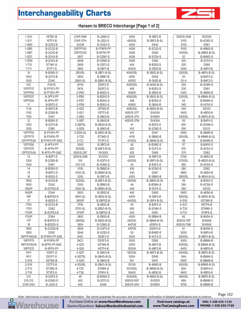
– 102 – www.zsi-inc.com
Interchangeability ChartsHansen to BRECO Interchange [Page 1 of 2]
1-S10 1STM1-B1-S11 1STF1-B1-SB3 B-2CE2-B1-SB5 B-2CG2-B1-SB7 B-2CH2-B1-SD7 B-2CH3-B1-SD9 B-2CK3-B1-T10 ST1M1-S1-T11 ST1F1-S
10 B-B2M2-S1000 B-2CF2-B1000 D34010C P341G
10FFP37 B-FF3F3-FP10FFP50 B-FF3F4-FP10FFS37 B-3FF3-FP10FFS50 B-3FF4-FP
11 B-B2F2-S11-B B-B2F2-B1100 B-2CM2-B1100 D34112 B-B2M1-S
1200 B-2CF3-B1200 D360
12FFP50 B-FF4F4-FP12FFP75 B-FF4F6-FP
12FFP75UN B-FF4F4-FP-SAE12FFS50 B-4FF4-FP12FFS75 B-4FF6-FP
12FFS75UN B-4FF4-FP-SAE13 B-B2F1-S
1300 B-2CM3-B1300 D361
14 B-B2M3-S15 B-B2F3-S16 B-B2S2-S
1600 B-2CS2-B1600 D342
1600P B-2CPS2-B1600P D344
16P B-B2PS2-S17 B-B2S3-S
1700 B-2CS3-B1700 D362
1700P B-2CPS3-B1700P D364
17P B-B2PS3-S18 B-B2S25-S
1800 B-2CS25-B1800 D352
19FFP106UN B-FF6F6-FP-SAE19FFP75 B-FF6F6-FP
19FFS106UN B-6FF6-FP-SAE19FFS75 B-6FF6-FP
1H11 1DSF1-S1K11 DS1F1-S2-S15 2STM2-B2-S16 2STF2-B2-T15 ST2M2-S2-T16 ST2F2-S210 B-2OF2-S
210-212 B-2OM2-S21AP-25H B-J2S2-S
21AP-25M B-J2M2-S21AP-37H B-J2S3-S
22238 B-O2S3-S25FFP100 B-FF8F8-FP25FFS100 B-8FF8-FP
2607 B-O2M1-S2608 B-O2M2-S2609 B-O2F2-S2800 B-2BF1-B
2800SL B-2BF1-B-SL2900 B-2BM1-B
2900-SL B-2BM1-B-SL2H16 2DSF2-S2K16 DS2F2-S
3-PB3 B-B2E2-S3-PB5 B-B2H2-S3-PD7 B-B2H3-S3-PD9 B-B2K3-S3-S20 3STM3-B3-S21 3STF3-B3-SB3 B-2BE2-B3-SB7 B-2BH2-B
3-SB7SL B-2BH2-B-SL3-SD9 B-2BK3-B
3-SD9-SL B-2BK3-B-SL3-T20 ST3M3-S3-T21 ST3F3-S3000 B-2BF2-B
3000SL B-2BF2-B-SL30SVS-25F SV300330SVS-25M SV3103
310 B-3OF3-S310-313 B-3OM3-S
3100 B-2BM2-B3100-SL B-2BM2-B-SL
3200 B-2BF3-B3200SL B-2BF3-B-SL
3300 B-2BM3-B3300-SL B-2BM3-B-SL
3600 B-2BS2-B3600-SL B-2BS2-B-SL3600P B-2BPS2-B3700 B-2BS3-B
3700-SL B-2BS3-B-SL3700P B-2BPS3-B3800 B-2BS5-B
3800SL B-2BS5-B-SL3804 B-O3M3-S3806 B-O3F3-S3946 B-O2S2-S3H21 3DSF3-S3K21 DS3F3-S4-S25 4STM4-B4-S26 4STF4-B4-SD7 B-3BH3-B
4-SD7SL B-3BH3-B-SL4-SD9 B-3BK3-B
4-SD9SL B-3BK3-B-SL4-T25 ST4M4-S4-T26 ST4F4-S
40 B-B3M2-S400 B-3CF2-S400 D440
4000 B-3BF2-B4000SL B-3BF2-B-SL
4004 D4424006 B-3CS3-S4006 D4624008 B-3CS4-S4008 D482404 B-B3S2-S
40400 B-3BS2-B40400SL B-3BS2-B-SL
4050 D45240500 B-3bS5-B
40500SL B-3bS5-B-SL406 B-B3S3-S
40600 B-3BS3-B40600SL B-3BS3-B-SL
408 B-B3S4-S40800 B-3BS4-B
40800SL B-3BS4-B-SL40SVS-37F SV420440SVS-37H SV480440SVS-37M SV4304
41 B-B3F2-S410 B-3CM2-S410 D441
4100 B-3BM2-B4100SL B-3BM2-B-SL
42 B-B3M3-S420 B-3CF3-S420 D460
4200 B-3BF3-B4200SL B-3BF3-B-SL
43 B-B3F3-S430 B-3CM3-S430 D461
4300 B-3BM3-B4300SL B-3BM3-B-SL
44 B-B3M4-S440 B-3CF4-S440 D480
4400 B-3BF4-B4400SL B-3BF4-B-SL
45 B-B3F4-S450 B-3CM4-S450 D481
4500 B-3BM4-B4500SL B-3BM4-B-SL4HP26 4DSF4-S4KP26 DS4F4-S
50 B-B4M2-S5000 B-4CF3-S5000 D5605000 B-4BF3-B
5000A B-4BF2-B5000SL B-4BF3-B-SL
500A D540501 D541
50100 B-4BM2-B50100SL B-4BM2-B-SL
50400 B-4BS2-B50400SL B-4BS2-B-SL
50SVS-50F SV520550SVS-50H SV5805
50SVS-50M SV53055100 B-4CM3-S5100 D5615100 B-4BM3-B
5100SL B-4BM3-B-SL52 B-B4M3-S
520 B-4CF4-S520 D580
5200 B-4BF4-B5200SL B-4BF4-B-SL
53 B-B4F3-S53-A B-B4F2-S530 B-4CM4-S530 D581
5300 B-4BM4-B5300SL B-4BM4-B-SL
54 B-B4M4-S540 B-4CF6-S540 D5120
5400 B-4BF6-B5400SL B-4BF6-B-SL
55 B-B4F4-S550 B-4CM6-S550 D5121
5500 B-4BM6-B5500SL B-4BM6-B-SL
56 B-B4M6-S57 B-B4F6-S570 B-4CS3-S570 D562
5700 B-4BS3-B5700SL B-4BS3-B-SL
580 B-4CS4-S580 D582
5800 B-4BS4-B5800SL B-4BS4-B-SL
59 B-B4S3-S590 B-4CS6-S590 D5122
5900 B-4BS6-B5900SL B-4BS6-B-SL6-S30 6STM6-B6-S31 6STF6-B6-T30 ST6M6-S6-T31 ST6F6-S
60 B-B4S4-S60SVS-75F SV640660SVS-75M SV6506
61 B-B4S6-S6200 B-6BF4-B
6200SL B-6BF4-B-SL6300 B-6BM4-B
6300SL B-6BM4-B-SL6400 B-6BF6-B
6400SL B-6BF6-B-SL64A B-B6M4-S6500 B-6BM6-B
6500SL B-6BM6-B-SL65A B-B6F4-S6600 B-6BF8-B
6600SL B-6BF8-B-SL66A B-B6M6-S6700 B-6BM8-B
Note: Interchange is based on best available information. We cannot guarantee the accuracy and recommend confirmation of detailed specifications prior to ordering.Page 102
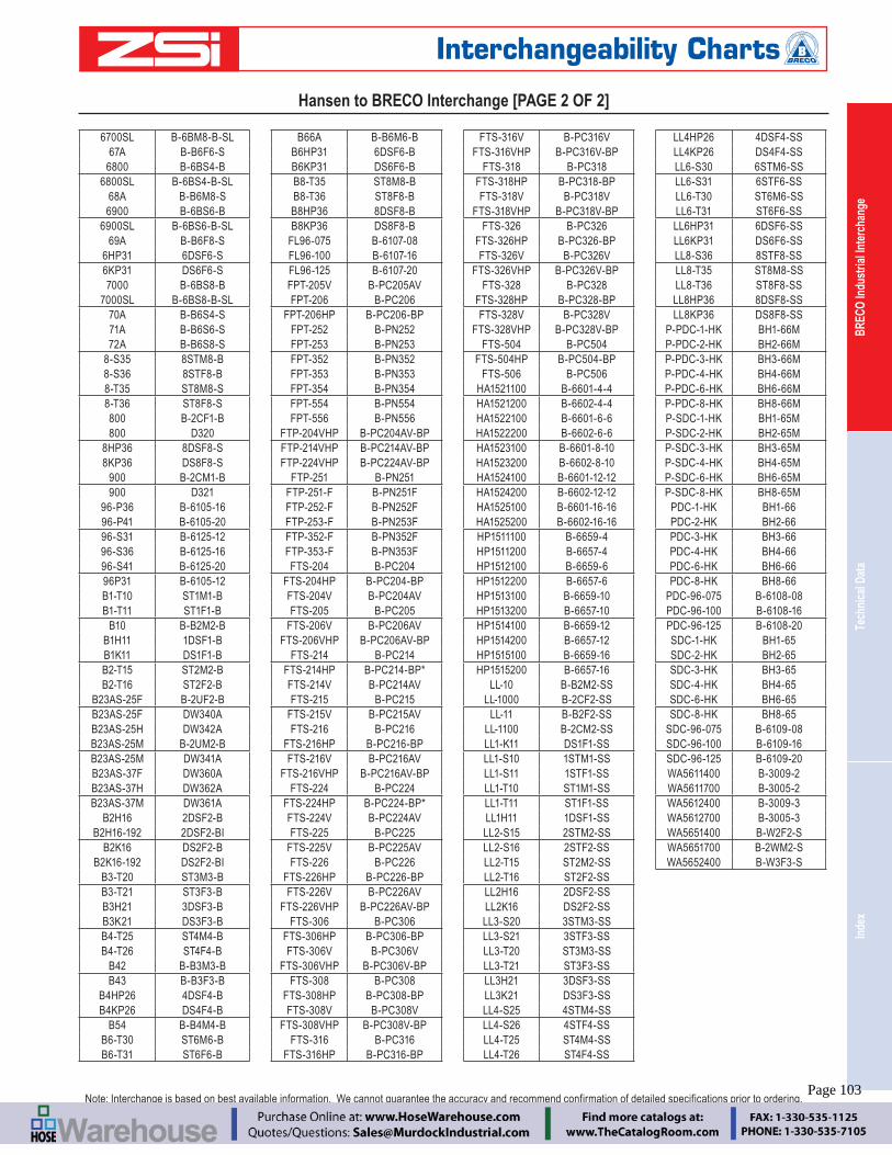
Inde
xTe
chni
cal D
ata
BREC
O In
dust
rial I
nter
chan
ge
Engineering Catalog www.zsi-inc.com – 103 –
Interchangeability Charts
6700SL B-6BM8-B-SL67A B-B6F6-S
6800 B-6BS4-B6800SL B-6BS4-B-SL
68A B-B6M8-S6900 B-6BS6-B
6900SL B-6BS6-B-SL69A B-B6F8-S
6HP31 6DSF6-S6KP31 DS6F6-S7000 B-6BS8-B
7000SL B-6BS8-B-SL70A B-B6S4-S71A B-B6S6-S72A B-B6S8-S
8-S35 8STM8-B8-S36 8STF8-B8-T35 ST8M8-S8-T36 ST8F8-S800 B-2CF1-B800 D320
8HP36 8DSF8-S8KP36 DS8F8-S
900 B-2CM1-B900 D321
96-P36 B-6105-1696-P41 B-6105-2096-S31 B-6125-1296-S36 B-6125-1696-S41 B-6125-2096P31 B-6105-12B1-T10 ST1M1-BB1-T11 ST1F1-B
B10 B-B2M2-BB1H11 1DSF1-BB1K11 DS1F1-BB2-T15 ST2M2-BB2-T16 ST2F2-B
B23AS-25F B-2UF2-BB23AS-25F DW340AB23AS-25H DW342AB23AS-25M B-2UM2-BB23AS-25M DW341AB23AS-37F DW360AB23AS-37H DW362AB23AS-37M DW361A
B2H16 2DSF2-BB2H16-192 2DSF2-BI
B2K16 DS2F2-BB2K16-192 DS2F2-BI
B3-T20 ST3M3-BB3-T21 ST3F3-BB3H21 3DSF3-BB3K21 DS3F3-BB4-T25 ST4M4-BB4-T26 ST4F4-B
B42 B-B3M3-BB43 B-B3F3-B
B4HP26 4DSF4-BB4KP26 DS4F4-B
B54 B-B4M4-BB6-T30 ST6M6-BB6-T31 ST6F6-B
B66A B-B6M6-BB6HP31 6DSF6-BB6KP31 DS6F6-BB8-T35 ST8M8-BB8-T36 ST8F8-BB8HP36 8DSF8-BB8KP36 DS8F8-B
FL96-075 B-6107-08FL96-100 B-6107-16FL96-125 B-6107-20FPT-205V B-PC205AVFPT-206 B-PC206
FPT-206HP B-PC206-BPFPT-252 B-PN252FPT-253 B-PN253FPT-352 B-PN352FPT-353 B-PN353FPT-354 B-PN354FPT-554 B-PN554FPT-556 B-PN556
FTP-204VHP B-PC204AV-BPFTP-214VHP B-PC214AV-BPFTP-224VHP B-PC224AV-BP
FTP-251 B-PN251FTP-251-F B-PN251FFTP-252-F B-PN252FFTP-253-F B-PN253FFTP-352-F B-PN352FFTP-353-F B-PN353FFTS-204 B-PC204
FTS-204HP B-PC204-BPFTS-204V B-PC204AVFTS-205 B-PC205
FTS-206V B-PC206AVFTS-206VHP B-PC206AV-BP
FTS-214 B-PC214FTS-214HP B-PC214-BP*FTS-214V B-PC214AVFTS-215 B-PC215
FTS-215V B-PC215AVFTS-216 B-PC216
FTS-216HP B-PC216-BPFTS-216V B-PC216AV
FTS-216VHP B-PC216AV-BPFTS-224 B-PC224
FTS-224HP B-PC224-BP*FTS-224V B-PC224AVFTS-225 B-PC225
FTS-225V B-PC225AVFTS-226 B-PC226
FTS-226HP B-PC226-BPFTS-226V B-PC226AV
FTS-226VHP B-PC226AV-BPFTS-306 B-PC306
FTS-306HP B-PC306-BPFTS-306V B-PC306V
FTS-306VHP B-PC306V-BPFTS-308 B-PC308
FTS-308HP B-PC308-BPFTS-308V B-PC308V
FTS-308VHP B-PC308V-BPFTS-316 B-PC316
FTS-316HP B-PC316-BP
FTS-316V B-PC316VFTS-316VHP B-PC316V-BP
FTS-318 B-PC318FTS-318HP B-PC318-BPFTS-318V B-PC318V
FTS-318VHP B-PC318V-BPFTS-326 B-PC326
FTS-326HP B-PC326-BPFTS-326V B-PC326V
FTS-326VHP B-PC326V-BPFTS-328 B-PC328
FTS-328HP B-PC328-BPFTS-328V B-PC328V
FTS-328VHP B-PC328V-BPFTS-504 B-PC504
FTS-504HP B-PC504-BPFTS-506 B-PC506
HA1521100 B-6601-4-4HA1521200 B-6602-4-4HA1522100 B-6601-6-6HA1522200 B-6602-6-6HA1523100 B-6601-8-10HA1523200 B-6602-8-10HA1524100 B-6601-12-12HA1524200 B-6602-12-12HA1525100 B-6601-16-16HA1525200 B-6602-16-16HP1511100 B-6659-4HP1511200 B-6657-4HP1512100 B-6659-6HP1512200 B-6657-6HP1513100 B-6659-10HP1513200 B-6657-10HP1514100 B-6659-12HP1514200 B-6657-12HP1515100 B-6659-16HP1515200 B-6657-16
LL-10 B-B2M2-SSLL-1000 B-2CF2-SS
LL-11 B-B2F2-SSLL-1100 B-2CM2-SSLL1-K11 DS1F1-SSLL1-S10 1STM1-SSLL1-S11 1STF1-SSLL1-T10 ST1M1-SSLL1-T11 ST1F1-SSLL1H11 1DSF1-SSLL2-S15 2STM2-SSLL2-S16 2STF2-SSLL2-T15 ST2M2-SSLL2-T16 ST2F2-SSLL2H16 2DSF2-SSLL2K16 DS2F2-SSLL3-S20 3STM3-SSLL3-S21 3STF3-SSLL3-T20 ST3M3-SSLL3-T21 ST3F3-SSLL3H21 3DSF3-SSLL3K21 DS3F3-SSLL4-S25 4STM4-SSLL4-S26 4STF4-SSLL4-T25 ST4M4-SSLL4-T26 ST4F4-SS
LL4HP26 4DSF4-SSLL4KP26 DS4F4-SSLL6-S30 6STM6-SSLL6-S31 6STF6-SSLL6-T30 ST6M6-SSLL6-T31 ST6F6-SSLL6HP31 6DSF6-SSLL6KP31 DS6F6-SSLL8-S36 8STF8-SSLL8-T35 ST8M8-SSLL8-T36 ST8F8-SSLL8HP36 8DSF8-SSLL8KP36 DS8F8-SS
P-PDC-1-HK BH1-66MP-PDC-2-HK BH2-66MP-PDC-3-HK BH3-66MP-PDC-4-HK BH4-66MP-PDC-6-HK BH6-66MP-PDC-8-HK BH8-66MP-SDC-1-HK BH1-65MP-SDC-2-HK BH2-65MP-SDC-3-HK BH3-65MP-SDC-4-HK BH4-65MP-SDC-6-HK BH6-65MP-SDC-8-HK BH8-65M
PDC-1-HK BH1-66PDC-2-HK BH2-66PDC-3-HK BH3-66PDC-4-HK BH4-66PDC-6-HK BH6-66PDC-8-HK BH8-66
PDC-96-075 B-6108-08PDC-96-100 B-6108-16PDC-96-125 B-6108-20SDC-1-HK BH1-65SDC-2-HK BH2-65SDC-3-HK BH3-65SDC-4-HK BH4-65SDC-6-HK BH6-65SDC-8-HK BH8-65
SDC-96-075 B-6109-08SDC-96-100 B-6109-16SDC-96-125 B-6109-20WA5611400 B-3009-2WA5611700 B-3005-2WA5612400 B-3009-3WA5612700 B-3005-3WA5651400 B-W2F2-SWA5651700 B-2WM2-SWA5652400 B-W3F3-S
Hansen to BRECO Interchange [PAGE 2 OF 2]
Note: Interchange is based on best available information. We cannot guarantee the accuracy and recommend confirmation of detailed specifications prior to ordering.Page 103
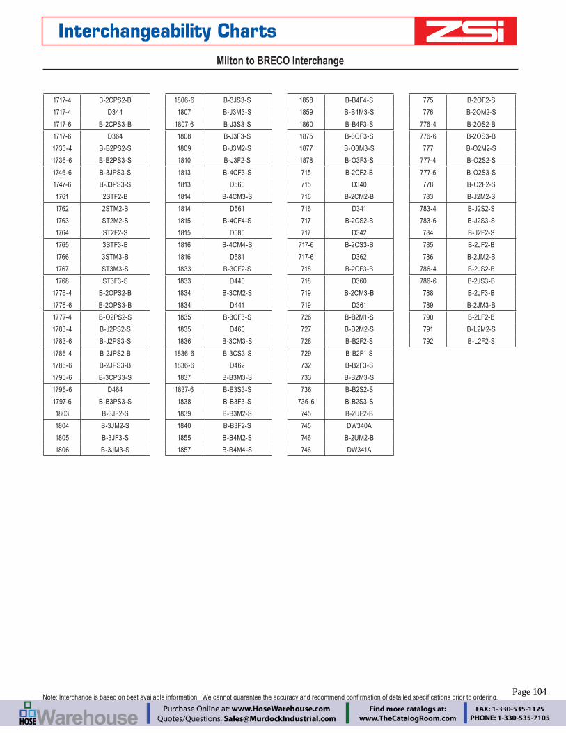
– 104 – www.zsi-inc.com
Interchangeability ChartsMilton to BRECO Interchange
1717-4 B-2CPS2-B
1717-4 D344
1717-6 B-2CPS3-B
1717-6 D364
1736-4 B-B2PS2-S
1736-6 B-B2PS3-S
1746-6 B-3JPS3-S
1747-6 B-J3PS3-S
1761 2STF2-B
1762 2STM2-B
1763 ST2M2-S
1764 ST2F2-S
1765 3STF3-B
1766 3STM3-B
1767 ST3M3-S
1768 ST3F3-S
1776-4 B-2OPS2-B
1776-6 B-2OPS3-B
1777-4 B-O2PS2-S
1783-4 B-J2PS2-S
1783-6 B-J2PS3-S
1786-4 B-2JPS2-B
1786-6 B-2JPS3-B
1796-6 B-3CPS3-S
1796-6 D464
1797-6 B-B3PS3-S
1803 B-3JF2-S
1804 B-3JM2-S
1805 B-3JF3-S
1806 B-3JM3-S
1806-6 B-3JS3-S
1807 B-J3M3-S
1807-6 B-J3S3-S
1808 B-J3F3-S
1809 B-J3M2-S
1810 B-J3F2-S
1813 B-4CF3-S
1813 D560
1814 B-4CM3-S
1814 D561
1815 B-4CF4-S
1815 D580
1816 B-4CM4-S
1816 D581
1833 B-3CF2-S
1833 D440
1834 B-3CM2-S
1834 D441
1835 B-3CF3-S
1835 D460
1836 B-3CM3-S
1836-6 B-3CS3-S
1836-6 D462
1837 B-B3M3-S
1837-6 B-B3S3-S
1838 B-B3F3-S
1839 B-B3M2-S
1840 B-B3F2-S
1855 B-B4M2-S
1857 B-B4M4-S
1858 B-B4F4-S
1859 B-B4M3-S
1860 B-B4F3-S
1875 B-3OF3-S
1877 B-O3M3-S
1878 B-O3F3-S
715 B-2CF2-B
715 D340
716 B-2CM2-B
716 D341
717 B-2CS2-B
717 D342
717-6 B-2CS3-B
717-6 D362
718 B-2CF3-B
718 D360
719 B-2CM3-B
719 D361
726 B-B2M1-S
727 B-B2M2-S
728 B-B2F2-S
729 B-B2F1-S
732 B-B2F3-S
733 B-B2M3-S
736 B-B2S2-S
736-6 B-B2S3-S
745 B-2UF2-B
745 DW340A
746 B-2UM2-B
746 DW341A
775 B-2OF2-S
776 B-2OM2-S
776-4 B-2OS2-B
776-6 B-2OS3-B
777 B-O2M2-S
777-4 B-O2S2-S
777-6 B-O2S3-S
778 B-O2F2-S
783 B-J2M2-S
783-4 B-J2S2-S
783-6 B-J2S3-S
784 B-J2F2-S
785 B-2JF2-B
786 B-2JM2-B
786-4 B-2JS2-B
786-6 B-2JS3-B
788 B-2JF3-B
789 B-2JM3-B
790 B-2LF2-B
791 B-L2M2-S
792 B-L2F2-S
Note: Interchange is based on best available information. We cannot guarantee the accuracy and recommend confirmation of detailed specifications prior to ordering.Page 104
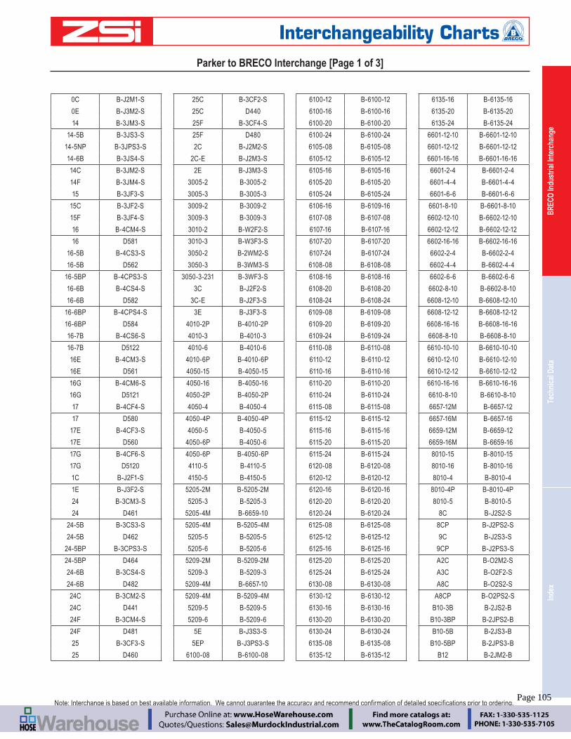
Inde
xTe
chni
cal D
ata
BREC
O In
dust
rial I
nter
chan
ge
Engineering Catalog www.zsi-inc.com – 105 –
Interchangeability Charts
0C B-J2M1-S
0E B-J3M2-S
14 B-3JM3-S
14-5B B-3JS3-S
14-5NP B-3JPS3-S
14-6B B-3JS4-S
14C B-3JM2-S
14F B-3JM4-S
15 B-3JF3-S
15C B-3JF2-S
15F B-3JF4-S
16 B-4CM4-S
16 D581
16-5B B-4CS3-S
16-5B D562
16-5BP B-4CPS3-S
16-6B B-4CS4-S
16-6B D582
16-6BP B-4CPS4-S
16-6BP D584
16-7B B-4CS6-S
16-7B D5122
16E B-4CM3-S
16E D561
16G B-4CM6-S
16G D5121
17 B-4CF4-S
17 D580
17E B-4CF3-S
17E D560
17G B-4CF6-S
17G D5120
1C B-J2F1-S
1E B-J3F2-S
24 B-3CM3-S
24 D461
24-5B B-3CS3-S
24-5B D462
24-5BP B-3CPS3-S
24-5BP D464
24-6B B-3CS4-S
24-6B D482
24C B-3CM2-S
24C D441
24F B-3CM4-S
24F D481
25 B-3CF3-S
25 D460
25C B-3CF2-S
25C D440
25F B-3CF4-S
25F D480
2C B-J2M2-S
2C-E B-J2M3-S
2E B-J3M3-S
3005-2 B-3005-2
3005-3 B-3005-3
3009-2 B-3009-2
3009-3 B-3009-3
3010-2 B-W2F2-S
3010-3 B-W3F3-S
3050-2 B-2WM2-S
3050-3 B-3WM3-S
3050-3-231 B-3WF3-S
3C B-J2F2-S
3C-E B-J2F3-S
3E B-J3F3-S
4010-2P B-4010-2P
4010-3 B-4010-3
4010-6 B-4010-6
4010-6P B-4010-6P
4050-15 B-4050-15
4050-16 B-4050-16
4050-2P B-4050-2P
4050-4 B-4050-4
4050-4P B-4050-4P
4050-5 B-4050-5
4050-6P B-4050-6
4050-6P B-4050-6P
4110-5 B-4110-5
4150-5 B-4150-5
5205-2M B-5205-2M
5205-3 B-5205-3
5205-4M B-6659-10
5205-4M B-5205-4M
5205-5 B-5205-5
5205-6 B-5205-6
5209-2M B-5209-2M
5209-3 B-5209-3
5209-4M B-6657-10
5209-4M B-5209-4M
5209-5 B-5209-5
5209-6 B-5209-6
5E B-J3S3-S
5EP B-J3PS3-S
6100-08 B-6100-08
6100-12 B-6100-12
6100-16 B-6100-16
6100-20 B-6100-20
6100-24 B-6100-24
6105-08 B-6105-08
6105-12 B-6105-12
6105-16 B-6105-16
6105-20 B-6105-20
6105-24 B-6105-24
6106-16 B-6109-16
6107-08 B-6107-08
6107-16 B-6107-16
6107-20 B-6107-20
6107-24 B-6107-24
6108-08 B-6108-08
6108-16 B-6108-16
6108-20 B-6108-20
6108-24 B-6108-24
6109-08 B-6109-08
6109-20 B-6109-20
6109-24 B-6109-24
6110-08 B-6110-08
6110-12 B-6110-12
6110-16 B-6110-16
6110-20 B-6110-20
6110-24 B-6110-24
6115-08 B-6115-08
6115-12 B-6115-12
6115-16 B-6115-16
6115-20 B-6115-20
6115-24 B-6115-24
6120-08 B-6120-08
6120-12 B-6120-12
6120-16 B-6120-16
6120-20 B-6120-20
6120-24 B-6120-24
6125-08 B-6125-08
6125-12 B-6125-12
6125-16 B-6125-16
6125-20 B-6125-20
6125-24 B-6125-24
6130-08 B-6130-08
6130-12 B-6130-12
6130-16 B-6130-16
6130-20 B-6130-20
6130-24 B-6130-24
6135-08 B-6135-08
6135-12 B-6135-12
6135-16 B-6135-16
6135-20 B-6135-20
6135-24 B-6135-24
6601-12-10 B-6601-12-10
6601-12-12 B-6601-12-12
6601-16-16 B-6601-16-16
6601-2-4 B-6601-2-4
6601-4-4 B-6601-4-4
6601-6-6 B-6601-6-6
6601-8-10 B-6601-8-10
6602-12-10 B-6602-12-10
6602-12-12 B-6602-12-12
6602-16-16 B-6602-16-16
6602-2-4 B-6602-2-4
6602-4-4 B-6602-4-4
6602-6-6 B-6602-6-6
6602-8-10 B-6602-8-10
6608-12-10 B-6608-12-10
6608-12-12 B-6608-12-12
6608-16-16 B-6608-16-16
6608-8-10 B-6608-8-10
6610-10-10 B-6610-10-10
6610-12-10 B-6610-12-10
6610-12-12 B-6610-12-12
6610-16-16 B-6610-16-16
6610-8-10 B-6610-8-10
6657-12M B-6657-12
6657-16M B-6657-16
6659-12M B-6659-12
6659-16M B-6659-16
8010-15 B-8010-15
8010-16 B-8010-16
8010-4 B-8010-4
8010-4P B-8010-4P
8010-5 B-8010-5
8C B-J2S2-S
8CP B-J2PS2-S
9C B-J2S3-S
9CP B-J2PS3-S
A2C B-O2M2-S
A3C B-O2F2-S
A8C B-O2S2-S
A8CP B-O2PS2-S
B10-3B B-2JS2-B
B10-3BP B-2JPS2-B
B10-5B B-2JS3-B
B10-5BP B-2JPS3-B
B12 B-2JM2-B
Parker to BRECO Interchange [Page 1 of 3]
Note: Interchange is based on best available information. We cannot guarantee the accuracy and recommend confirmation of detailed specifications prior to ordering.Page 105

– 106 – www.zsi-inc.com
Interchangeability Charts
B12E B-2JM3-B
B13 B-2JF2-B
B13A B-2JF1-B
B13E B-2JF3-B
B14 B-3JM3-B
B15 B-3JF3-B
B16 B-4CM4-B
B17 B-4CF4-B
B20-3B B-2CS2-B
B20-3B D342
B20-3BP B-2CPS2-B
B20-3BP D344
B20-5B B-2CS3-B
B20-5B D362
B20-5BP B-2CPS3-B
B20-5BP D364
B22 B-2CM2-B
B22 D341
B22A B-2CM1-B
B22A D321
B22E B-2CM3-B
B22E D361
B23 B-2CF2-B
B23 D340
B23A B-2CF1-B
B23A D320
B23E B-2CF3-B
B23E D360
B24 B-3CM3-B
B25 B-3CF3-B
B2C B-J2M2-B
B30-3B B-2BS2-B
B30-3BP B-2BPS2-B
B30-5B B-2BS3-B
B30-5BP B-2BPS3-B
B32 B-2BM2-B
B32A B-2BM1-B
B32E B-2BM3-B
B33 B-2BF2-B
B33-SL B-2BF2-B-SL
B33A B-2BF1-B
B33E B-2BF3-B
B34 B-3BM3-B
B34-5B B-3BS3-B
B34-5BP B-3BPS3-B
B34-6B B-3BS4-B
B34C B-3BM2-B
B34F B-3BM4-B
B35 B-3BF3-B
B35-SL B-3BF3-B-SL
B35C B-3BF2-B
B35F B-3BF4-B
B36 B-4BM4-B
B36-6B B-4BS4-B
B36-6BP B-4BPS4-B
B36-7B B-4BS6-B
B36E B-4BM3-B
B36G B-4BM6-B
B37 B-4BF4-B
B37-SL B-4BF4-B-SL
B37E B-4BF3-B
B37G B-4BF6-B
B38 B-6BM6-B
B38-7B B-6BS6-B
B38-8B B-6BS8-B
B38J B-6BM8-B
B39 B-6BF6-B
B39F B-6BF4-B
B39J B-6BF8-B
B3C B-J2F2-B
B50-3BP B-2OPS2-B
B50-5BP B-2OPS3-B
B52 B-2OM2-B
B52E B-2OM3-B
B53 B-2OF2-B
B53E B-2OF3-B
B72 B-2LM2-B
B73 B-2LF2-B
BH1-60 1DSF1-B
BH1-61 DS1F1-B
BH2-60 2DSF2-B
BH2-60-W 2DSF2-BI
BH2-61 DS2F2-B
BH2-61-W DS2F2-BI
BH2C B-B2M2-B
BH2E B-B3M3-B
BH2F B-B4M4-B
BH2G B-B6M6-B
BH3-60 3DSF3-B
BH3-61 DS3F3-B
BH3C B-B2F2-B
BH3E B-B3F3-B
BH3F B-B4F4-B
BH4-60 4DSF4-B
BH4-61 DS4F4-B
BH6-60 6DSF6-B
BH6-61 DS6F6-B
BH8-60 8DSF8-B
BH8-61 DS8F8-B
BPN251F B-BPN251F
BPN252F B-BPN252F
BPN253F B-BPN253F
BPN352F B-BPN352F
BPN353F B-BPN353F
BST-1 1STF1-B
BST-1M 1STM1-B
BST-2 2STF2-B
BST-2M 2STM2-B
BST-3 3STF3-B
BST-3M 3STM3-B
BST-4 4STF4-B
BST-4M 4STM4-B
BST-6 6STF6-B
BST-6M 6STM6-B
BST-8 8STF8-B
BST-8M 8STM8-B
BST-N1 ST1F1-B
BST-N1M ST1M1-B
BST-N2 ST2F2-B
BST-N2M ST2M2-B
BST-N3 ST3F3-B
BST-N3M ST3M3-B
BST-N4 ST4F4-B
BST-N4M ST4M4-B
BST-N6 ST6F6-B
BST-N6M ST6M6-B
BST-N8 ST8F8-B
BST-N8M ST8M8-B
EZ-251-4FP SV3003
EZ-251-4HB SV3603
EZ-251-4MP SV3103
EZ-251-4PL SV1513
EZ-251-6FP SV3203
EZ-251-6HB SV3703
EZ-251-6MP SV3303
EZ-251-6PL SV1713
EZ-371-6FP SV4204
EZ-371-6HB SV4804
EZ-371-6MP SV4304
EZ-371-6PL SV1714
EZ-501-12FP SV5405
EZ-501-8FP SV5205
EZ-501-8HB SV5805
EZ-501-8MP SV5305
EZ-501-8PL SV1815
EZ-751-12FP SV6406
EZ-751-12MP SV6506
EZ-751-16FP SV6606
FE-501-12FO B-4FF6-FP-SAE
FE-502-12FO B-FF4F6-FP-SAE
FE501-8FP B-4FF4-FP
FE502-12FP B-FF4F6-FP
FF-371-6FP B-3FF3-FP
FF-371-8FP B-3FF4-FP
FF-372-6FP B-FF3F3-FP
FF-372-8FP B-FF3F4-FP
FF502-8FP B-FF4F4-FP
FR-1001 PDC-8
FR-1002 SDC-8
FR-501 PDC-4
FR-502 SDC-4
FR-751 PDC-6
FR-752 SDC-6
H0C B-B2M1-S
H0E B-B3M2-S
H0F B-B4M3-S
H1-62 1DSF1-S
H1-63 DS1F1-S
H1-65 BH1-65
H1-65M B-6659-4
H1-65M BH1-65M
H1-66 BH1-66
H1-66M B-6657-4
H1-66M BH1-66M
H1C B-B2F1-S
H1E B-B3F2-S
H1F B-B4F3-S
H2-62 2DSF2-S
H2-63 DS2F2-S
H2-65 BH2-65
H2-65M BH2-65M
H2-66 BH2-66
H2-66M BH2-66M
H2C B-B2M2-S
H2CE B-B2M3-S
H2E B-B3M3-S
H2E-F B-B3M4-S
H2F B-B4M4-S
H2F-G B-B4M6-S
H2G B-B6M6-S
H2G-F B-B6M4-S
H2G-J B-B6M8-S
H3-62 3DSF3-S
H3-63 DS3F3-S
H3-65 BH3-65
H3-65M BH3-65M
H3-66 BH3-66
H3-66M BH3-66M
H3C B-B2F2-S
H3C-E B-B2F3-S
H3E B-B3F3-S
H3E-F B-B3F4-S
H3F B-B4F4-S
H3F-G B-B4F6-S
Parker to BRECO Interchange [PAGE 2 OF 3]
Note: Interchange is based on best available information. We cannot guarantee the accuracy and recommend confirmation of detailed specifications prior to ordering.Page 106

Inde
xTe
chni
cal D
ata
BREC
O In
dust
rial I
nter
chan
ge
Engineering Catalog www.zsi-inc.com – 107 –
Interchangeability Charts
H3G B-B6F6-S
H3G-F B-B6F4-S
H3G-J B-B6F8-S
H4-62 4DSF4-S
H4-63 DS4F4-S
H4-65 BH4-65
H4-65M BH4-65M
H4-66 BH4-66
H4-66M BH4-66M
H4EP B-B3PS2-S
H4F B-B4S3-S
H4FP B-B4PS3-S
H5E B-B3S3-S
H5EP B-B3PS3-S
H5F B-B4S4-S
H5F-G B-B4S6-S
H5FP B-B4PS4-S
H5G B-B6S6-S
H5G-F B-B6S4-S
H5G-J B-B6S8-S
H6-62 6DSF6-S
H6-63 DS6F6-S
H6-65 BH6-65
H6-65M BH6-65M
H6-66 BH6-66
H6-66M BH6-66M
H6E B-B3S4-S
H6EP B-B3PS4-S
H8-62 8DSF8-S
H8-63 DS8F8-S
H8-65 BH8-65
H8-65M BH8-65M
H8-66 BH8-66
H8-66M BH8-66M
H8C B-B2S2-S
H8C-D B-B2S25-S
H8CP B-B2PS2-S
H9C B-B2S3-S
H9CP B-B2PS3-S
L2C B-L2M2-S
L3C B-L2F2-S
NR-37 SDC-3
NR-50 PDC-3
PC204 B-PC204
PC204-AV B-PC204AV
PC204-BP B-PC204-BP
PC204AV-BP B-PC204AV-BP
PC205 B-PC205
PC205AV B-PC205AV
PC206 B-PC206
PC206-BP B-PC206-BP
PC206AV B-PC206AV
PC206AV-BP B-PC206AV-BP
PC214 B-PC214
PC214-BP B-PC214-BP*
PC214AV B-PC214AV
PC214AV-BP B-PC214AV-BP
PC215 B-PC215
PC215AV B-PC215AV
PC216 B-PC216
PC216-BP B-PC216-BP
PC216AV B-PC216AV
PC216AV-BP B-PC216AV-BP
PC224 B-PC224
PC224-BP B-PC224-BP*
PC224AV B-PC224AV
PC224AV-BP B-PC224AV-BP
PC225 B-PC225
PC225AV B-PC225AV
PC226 B-PC226
PC226-BP B-PC226-BP
PC226AV B-PC226AV
PC226AV-BP B-PC226AV-BP
PC306 B-PC306
PC306-BP B-PC306-BP
PC306V B-PC306V
PC306V-BP B-PC306V-BP
PC308 B-PC308
PC308-BP B-PC308-BP
PC308V B-PC308V
PC308V-BP B-PC308V-BP
PC316 B-PC316
PC316-BP B-PC316-BP
PC316V B-PC316V
PC316V-BP B-PC316V-BP
PC318 B-PC318
PC318-BP B-PC318-BP
PC318V B-PC318V
PC318V-BP B-PC318V-BP
PC326 B-PC326
PC326-BP B-PC326-BP
PC326V B-PC326V
PC326V-BP B-PC326V-BP
PC328 B-PC328
PC328-BP B-PC328-BP
PC328V B-PC328V
PC328V-BP B-PC328V-BP
PC504 B-PC504
PC504-BP B-PC504-BP
PC506 B-PC506
PN251 B-PN251
PN251F B-PN251F
PN252 B-PN252
PN252F B-PN252F
PN253 B-PN253
PN253F B-PN253F
PN352 B-PN352
PN352F B-PN352F
PN353 B-PN353
PN353F B-PN353F
PN354 B-PN354
PN554 B-PN554
PN556 B-PN556
S22 B-2CM2-SS
S23 B-2CF2-SS
SH1-62 1DSF1-SS
SH1-63 DS1F1-SS
SH2-62 2DSF2-SS
SH2-63 DS2F2-SS
SH2C B-B2M2-SS
SH3-62 3DSF3-SS
SH3-63 DS3F3-SS
SH3C B-B2F2-SS
SH4-62 4DSF4-SS
SH4-63 DS4F4-SS
SH6-62 6DSF6-SS
SH6-63 DS6F6-SS
SH8-62 8DSF8-SS
SH8-63 DS8F8-SS
SST-1 1STF1-SS
SST-1M 1STM1-SS
SST-2 2STF2-SS
SST-2M 2STM2-SS
SST-3 3STF3-SS
SST-3M 3STM3-SS
SST-4 4STF4-SS
SST-4M 4STM4-SS
SST-6 6STF6-SS
SST-6M 6STM6-SS
SST-8 8STF8-SS
SST-8M 8STM8-SS
SST-N1 ST1F1-SS
SST-N1M ST1M1-SS
SST-N2 ST2F2-SS
SST-N2M ST2M2-SS
SST-N3 ST3F3-SS
SST-N3M ST3M3-SS
SST-N4 ST4F4-SS
SST-N4M ST4M4-SS
SST-N6 ST6F6-SS
SST-N6M ST6M6-SS
SST-N8 ST8F8-SS
SST-N8M ST8M8-SS
ST-N1 ST1F1-S
ST-N1M ST1M1-S
ST-N2 ST2F2-S
ST-N2M ST2M2-S
ST-N3 ST3F3-S
ST-N3M ST3M3-S
ST-N4 ST4F4-S
ST-N4M ST4M4-S
ST-N6 ST6F6-S
ST-N6M ST6M6-S
ST-N8 ST8F8-S
ST-N8M ST8M8-S
TL-251-4FP B-2TLF2-S
TL-251-4MP B-2TLM2-S
TL-251-6MP B-2TLM3-S
TL-254-2FP B-TL2F1-S
TL-254-2MP B-TL2M1-S
TL-254-4FP B-TL2F2-S
TL-254-4HB B-TL2S2-S
TL-254-4MP B-TL2M2-S
TL-501-12FP B-4TLF6-S
TL-501-6FP B-4TLF3-S
TL-501-6MP B-4TLM3-S
TL-501-8FP B-4TLF4-S
TL-501-8MP B-4TLM4-S
TL-504-12MP B-TL4M6-S
TL-504-4FP B-TL4F2-S
TL-504-4MP B-TL4M2-S
TL-504-6FP B-TL4F3-S
TL-504-6MP B-TL4M3-S
TL-504-8MP B-TL4M4-S
TR-37 B-6659-6
TR-37 B-6657-6
UC-251-4FP B-2UF2-B
UC-251-4FP DW340A
UC-251-4MP B-2UM2-B
UC-251-4MP DW341A
UC-251-6FP DW360A
UC-251-6MP DW361A
Parker to BRECO Interchange [PAGE 3 OF 3]
Note: Interchange is based on best available information. We cannot guarantee the accuracy and recommend confirmation of detailed specifications prior to ordering.Page 107

– 108 – www.zsi-inc.com
Interchangeability Charts
PCC to BRECO Interchange [PAGE 1 OF 3]
10WDP-B B-6109-2010WF10-B B-6125-2012WDP-B B-6109-2412WF12-B B-6125-24
1EF1-B 1STF1-B1EF1-S 1STF1-SS1EM1-B 1STM1-B1EM1-S 1STM1-SS
1HF1 1DSF1-S1HF1-B 1DSF1-B1HF1-S 1DSF1-SS2AGDP B-5205-2M2AGF2 B-4050-2P
2AGF2-PV B-4050-22CM4B2-B B-PC224AV-BP
2CM4B2-B-E B-PC224-BP*2CM4B3-B B-PC226AV-BP
2CM4B3-B-E B-PC226-BP2CM4S2-B B-PC224AV
2CM4S2-B-E B-PC2242CM4S2.5-B B-PC225AV
2CM4S2.5-B-E B-PC2252CM4S3-B B-PC226AV
2CM4S3-B-E B-PC2262CM9B2-B B-PC214AV-BP
2CM9B2-B-E B-PC214-BP*2CM9B3-B B-PC216AV-BP
2CM9B3-B-E B-PC216-BP2CM9S2-B B-PC214AV
2CM9S2-B-E B-PC2142CM9S2.5-B B-PC215AV
2CM9S2.5-B-E B-PC2152CM9S3-B B-PC216AV
2CM9S3-B-E B-PC2162CMB2-B B-PC204AV-BP
2CMB2-B-E B-PC204-BP2CMB3-B B-PC206AV-BP
2CMB3-B-E B-PC206-BP2CMS2-B B-PC204AV
2CMS2-B-E B-PC2042CMS2.5-B B-PC205AV
2CMS2.5-B-E B-PC2052CMS3-B B-PC206AV
2CMS3-B-E B-PC2062DB2-B B-2BPS2-B2DB3-B B-2BPS3-B2DF1-B B-2BF1-B2DF2-B B-2BF2-B2DF3-B B-2BF3-B2DM1-B B-2BM1-B2DM2-B B-2BM2-B2DM3-B B-2BM3-B2DS2-B B-2BS2-B2DS3-B B-2BS3-B2EF2-B 2STF2-B2EF2-S 2STF2-SS2EM2-B 2STM2-B2EM2-S 2STM2-SS2FB2-B B-2CPS2-B2FB2-B D3442FB3-B B-2CPS3-B2FB3-B D3642FF1-B B-2CF1-B2FF1-B D3202FF2-B B-2CF2-B2FF2-B D340
2FF2-S B-2CF2-SS2FF3-B B-2CF3-B2FF3-B D3602FM1-B B-2CM1-B2FM1-B D3212FM2-B B-2CM2-B2FM2-B D3412FM2-S B-2CM2-SS2FM3-B B-2CM3-B2FM3-B D3612FS2-B B-2CS2-B2FS2-B D342
2FS2.5-B B-2CS25-B2FS3-B B-2CS3-B2FS3-B D3622HDP BH2-65M
2HDP-A BH2-652HF2 2DSF2-S
2HF2-B 2DSF2-B2HF2-S 2DSF2-SS2JB2-B B-2JPS2-B2JB3-B B-2JPS3-B2JF1-B B-2JF1-B2JF2-B B-2JF2-B2JF3-B B-2JF3-B2JM2-B B-2JM2-B2JM3-B B-2JM3-B2JS2-B B-2JS2-B2JS3-B B-2JS3-B2KDP B-6659-42KF1 B-6601-2-42KF2 B-6601-4-4
2LF2-B B-2LF2-B2LM2-B B-2LM2-B2MF2-B B-2OF2-B
2MF2-PL B-2OF2-S2MF3-B B-2OF3-B2MM2-B B-2OM2-B
2MM2-PL B-2OM2-S2MM3-B B-2OM3-B2MS2-B B-2OS2-B2MS3-B B-2OS3-B2SHDF2 B-2TLF2-S2SHDF3 B-2TLF3-S2SHDM2 B-2TLM2-S2SHDM3 B-2TLM3-S
2TDP B-3005-22TM2 B-2WM2-S
2UF2-B B-2UF2-B2UF2-B DW340A2UF3-B DW360A2UM2-B B-2UM2-B2UM2-B DW341A2UM3-B DW361A2US2-B DW342A2US3-B DW362A
2VF2 B-VHC4-4F2VF2-B B-VHC4-4F-B
2VF2-B-E B-PHC4-4F-B2VF2-E B-PHC4-4F2VM2 B-VHC4-4M
2VM2-B B-VHC4-4M-B2VM2-B-E B-PHC4-4M-B2VM2-E B-PHC4-4M3AGDP B-5205-33AGF3 B-4050-3
3CM4B3-B B-PC326V-BP3CM4B3-B-E B-PC326-BP3CM4B4-B B-PC328V-BP
3CM4B4-B-E B-PC328-BP3CM4S3-B B-PC326V
3CM4S3-B-E B-PC3263CM4S4-B B-PC328V
3CM4S4-B-E B-PC3283CM9B3-B B-PC316V-BP
3CM9B3-B-E B-PC316-BP3CM9B4-B B-PC318V-BP
3CM9B4-B-E B-PC318-BP3CM9S3-B B-PC316V
3CM9S3-B-E B-PC3163CM9S4-B B-PC318V
3CM9S4-B-E B-PC3183CMB3-B B-PC306V-BP
3CMB3-B-E B-PC306-BP3CMB4-B B-PC308V-BP
3CMB4-B-E B-PC308-BP3CMS3-B B-PC306V
3CMS3-B-E B-PC3063CMS4-B B-PC308V
3CMS4-B-E B-PC3083DB3-B B-3BPS3-B3DF2-B B-3BF2-B3DF3-B B-3BF3-B3DF4-B B-3BF4-B3DM2-B B-3BM2-B3DM3-B B-3BM3-B3DM4-B B-3BM4-B3DS2-B B-3BS2-B3DS3-B B-3BS3-B3DS4-B B-3BS4-B3EF3-B 3STF3-B3EF3-S 3STF3-SS3EM3-B 3STM3-B3EM3-S 3STM3-SS
3FB3 B-3CPS3-S3FB3 D4643FF2 B-3CF2-S3FF2 D4403FF3 B-3CF3-S3FF3 D4603FF4 B-3CF4-S3FF4 D4803FM2 B-3CM2-S3FM2 D4413FM3 B-3CM3-S3FM3 D4613FM4 B-3CM4-S3FM4 D4813FS2 D4423FS3 B-3CS3-S3FS3 D4623FS4 B-3CS4-S3FS4 D4823HDP BH3-65M
3HDP-A BH3-653HF3 3DSF3-S
3HF3-B 3DSF3-B3HF3-S 3DSF3-SS3HTDP PDC-33HTF3 B-3FF3-FP3HTF4 B-3FF4-FP3JB3 B-3JPS3-S
3JF2 B-3JF2-S3JF3 B-3JF3-S3JF4 B-3JF4-S3JM2 B-3JM2-S3JM3 B-3JM3-S3JM4 B-3JM4-S3JS3 B-3JS3-S3JS4 B-3JS4-S3KDP B-6659-63KF3 B-6601-6-6
3MF3-PL B-3OF3-S3MM3-PL B-3OM3-S
3TDP B-3005-33TF3 B-3WF3-S3TM3 B-3WM3-S
3UF3-B DW460A3UM3-B DW461A3US3-B DW462A
3VF3 B-VHC6-6F3VF3-B B-VHC6-6F-B
3VF3-B-E B-PHC6-6F-B3VF3-E B-PHC6-6F3VM3 B-VHC6-6M
3VM3-B B-VHC6-6M-B3VM3-B-E B-PHC6-6M-B3VM3-E B-PHC6-6M4AGF4 B-4050-4
4AGF4-PV B-4050-4P4AGF6 B-4050-5
4AGOF4 B-4050-154AGOF5 B-4050-16
4CMB4-B-E B-PC504-BP4CMS4-B-E B-PC5044CMS6-B-E B-PC506
4DB4-B B-4BPS4-B4DF3-B B-4BF3-B4DF4-B B-4BF4-B4DF6-B B-4BF6-B4DM3-B B-4BM3-B4DM4-B B-4BM4-B4DM6-B B-4BM6-B4DS3-B B-4BS3-B4DS4-B B-4BS4-B4DS6-B B-4BS6-B4EF4-B 4STF4-B4EF4-S 4STF4-SS4EM4-B 4STM4-B4EM4-S 4STM4-SS
4FB3 B-4CPS3-S4FB4 B-4CPS4-S4FB4 D5844FF3 B-4CF3-S4FF3 D5604FF4 B-4CF4-S4FF4 D5804FF6 B-4CF6-S4FM3 B-4CM3-S4FM3 D5614FM4 B-4CM4-S4FM4 D5814FM6 B-4CM6-S4FM6 D51214FS3 B-4CS3-S4FS3 D5624FS4 B-4CS4-S4FS4 D582
Note: Interchange is based on best available information. We cannot guarantee the accuracy and recommend confirmation of detailed specifications prior to ordering.Page 108

Inde
xTe
chni
cal D
ata
BREC
O In
dust
rial I
nter
chan
ge
Engineering Catalog www.zsi-inc.com – 109 –
Interchangeability ChartsPCC to BRECO Interchange [PAGE 2 OF 3]
4FS6 B-4CS6-S4FS6 D51224HDP BH4-65M
4HDP-A BH4-654HF4 4DSF4-S
4HF4-B 4DSF4-B4HF4-S 4DSF4-SS4HTDP PDC-44HTF4 B-4FF4-FP4HTF6 B-4FF6-FP
4HTOF4 B-4FF4-FP-SAE4HTOF6 B-4FF6-FP-SAE
4KDP B-5205-4M4KDP B-6659-104KF4 B-6601-8-104KF6 B-6601-12-10
4KOF4 B-6608-8-104SHDF3 B-4TLF3-S4SHDF4 B-4TLF4-S4SHDF6 B-4TLF6-S4SHDM3 B-4TLM3-S4SHDM4 B-4TLM4-S
4VF4 B-VHC8-8F4VF4-B B-VHC8-8F-B
4VF4-B-E B-PHC8-8F-B4VF4-E B-PHC8-8F4VM4 B-VHC8-8M
4VM4-B B-VHC8-8M-B4VM4-B-E B-PHC8-8M-B4VM4-E B-PHC8-8M6AGDP B-5205-56AGF6 B-4150-56DF4-B B-6BF4-B6DF6-B B-6BF6-B6DF8-B B-6BF8-B6DM4-B B-6BM4-B6DM6-B B-6BM6-B6DM8-B B-6BM8-B6DS4-B B-6BS4-B6DS6-B B-6BS6-B6DS8-B B-6BS8-B6EF6-B 6STF6-B6EF6-S 6STF6-SS6EM6-B 6STM6-B6EM6-S 6STM6-SS6HDP BH6-65M
6HDP-A BH6-656HF6 6DSF6-S
6HF6-B 6DSF6-B6HF6-S 6DSF6-SS6HTDP PDC-66HTF6 B-6FF6-FP
6HTOF6 B-6FF6-FP-SAE6KDP B-6659-126KF6 B-6601-12-12
6KOF6 B-6608-12-126VF6 B-VHC12-12F
6VF6-B B-VHC12-12F-B6VF6-B-E B-PHC12-12F-B6VF6-E B-PHC12-12F6VM6 B-VHC12-12M
6VM6-B B-VHC12-12M-B6VM6-B-E B-PHC12-12M-B6VM6-E B-PHC12-12M6WDP-B B-6109-086WF4-B B-6125-08
6WF6-B B-6125-128AGDP B-5205-68AGF8 B-4050-6
8AGF8-PV B-4050-6P8EF8-B 8STF8-B8EF8-S 8STF8-SS8EM8-B 8STM8-B8EM8-S 8STM8-SS8HDP BH8-65M
8HDP-A BH8-658HF8 8DSF8-S
8HF8-B 8DSF8-B8HF8-S 8DSF8-SS8HTDP PDC-88HTF8 B-8FF8-FP8KDP B-6659-168KF8 B-6601-16-16
8KOF8 B-6608-16-168WDP-B B-6109-168WF8-B B-6125-16AG2DC B-5209-2MAG2F2 B-4010-2
AG2F2-PV B-4010-2PAG3DP B-5209-3AG3F3 B-4010-3AG4F4 B-8010-4
AG4F4-PV B-8010-4PAG4F6 B-8010-5
AG4OF4 B-8010-15AG4OF5 B-8010-16AG6DC B-5209-5AG6F6 B-4110-5AG8DC B-5209-6AG8F8 B-4010-6
AG8F8-PV B-4010-6PB3B2 B-B3PS2-S
CM2F1 B-PN251FCM2F1-B B-BPN251FCM2F2 B-PN252F
CM2F2-B B-BPN252FCM2F3 B-PN253F
CM2F3-B B-BPN253FCM2M1-B B-PN251CM2M2-B B-PN252CM2M3-B B-PN253
CM3F2 B-PN352FCM3F2-B B-BPN352FCM3F3 B-PN353F
CM3F3-B B-BPN353FCM3M2-B B-PN352CM3M3-B B-PN353CM3M4-B B-PN354CM4M4-B B-PN554CM4M6-B B-PN556
D2B2 B-B2PS2-SD2B3 B-B2PS3-SD2E2 B-B2E2-SD2F1 B-B2F1-SD2F2 B-B2F2-S
D2F2-B B-B2F2-BD2F2-S B-B2F2-SSD2F3 B-B2F3-SD2M1 B-B2M1-SD2M2 B-B2M2-S
D2M2-B B-B2M2-BD2M2-S B-B2M2-SS
D2M3 B-B2M3-SD2S2 B-B2S2-S
D2S2.5 B-B2S25-SD2S3 B-B2S3-SD3B3 B-B3PS3-SD3B4 B-B3PS4-SD3F2 B-B3F2-SD3F3 B-B3F3-S
D3F3-B B-B3F3-BD3F4 B-B3F4-SD3M2 B-B3M2-SD3M3 B-B3M3-S
D3M3-B B-B3M3-BD3M4 B-B3M4-SD3S2 B-B3S2-SD3S3 B-B3S3-SD3S4 B-B3S4-SD4B4 B-B4PS4-SD4F3 B-B4F3-SD4F4 B-B4F4-S
D4F4-B B-B4F4-BD4F6 B-B4F6-SD4M2 B-B4M2-SD4M3 B-B4M3-SD4M4 B-B4M4-S
D4M4-B B-B4M4-BD4M6 B-B4M6-SD4S3 B-B4S3-SD4S4 B-B4S4-SD4S6 B-B4S6-SD6F4 B-B6F4-SD6F6 B-B6F6-SD6F8 B-B6F8-SD6M4 B-B6M4-SD6M6 B-B6M6-SD6M8 B-B6M8-SD6S4 B-B6S4-SD6S6 B-B6S6-SD6S8 B-B6S8-SE1F1 ST1F1-S
E1F1-B ST1F1-BE1F1-S ST1F1-SSE1M1 ST1M1-S
E1M1-B ST1M1-BE1M1-S ST1M1-SS
E2F2 ST2F2-SE2F2-B ST2F2-BE2F2-S ST2F2-SSE2M2 ST2M2-S
E2M2-B ST2M2-BE2M2-S ST2M2-SS
E3F3 ST3F3-SE3F3-B ST3F3-BE3F3-S ST3F3-SSE3M3 ST3M3-S
E3M3-B ST3M3-BE3M3-S ST3M3-SS
E4F4 ST4F4-SE4F4-B ST4F4-BE4F4-S ST4F4-SSE4M4 ST4M4-S
E4M4-B ST4M4-BE4M4-S ST4M4-SS
E6F6 ST6F6-SE6F6-B ST6F6-BE6F6-S ST6F6-SS
E6M6 ST6M6-SE6M6-B ST6M6-BE6M6-S ST6M6-SS
E8F8 ST8F8-SE8F8-B ST8F8-BE8F8-S ST8F8-SSE8M8 ST8M8-S
E8M8-B ST8M8-BE8M8-S ST8M8-SS
H1F1 DS1F1-SH1F1-B DS1F1-BH1F1-S DS1F1-SSH2DC BH2-66M
H2DC-A BH2-66H2F2 DS2F2-S
H2F2-B DS2F2-BH2F2-S DS2F2-SSH3DC BH3-66M
H3DC-A BH3-66H3F3 DS3F3-S
H3F3-B DS3F3-BH3F3-S DS3F3-SSH4DC BH4-66M
H4DC-A BH4-66H4F4 DS4F4-S
H4F4-B DS4F4-BH4F4-S DS4F4-SSH6DC BH6-66M
H6DC-A BH6-66H6F6 DS6F6-S
H6F6-B DS6F6-BH6F6-S DS6F6-SSH8DC BH8-66M
H8DC-A BH8-66H8F8 DS8F8-S
H8F8-B DS8F8-BH8F8-S DS8F8-SSHT3DC SDC-3HT3F3 B-FF3F3-FPHT3F4 B-FF3F4-FPHT4DC SDC-4HT4F4 B-FF4F4-FPHT4F6 B-FF4F6-FP
HT4OF4 B-FF4F4-FP-SAEHT4OF6 B-FF4F6-FP-SAEHT6DC SDC-6HT6F6 B-FF6F6-FP
HT6OF6 B-FF6F6-FP-SAEHT8DC SDC-8HT8F8 B-FF8F8-FPJ2B2 B-J2PS2-SJ2B3 B-J2PS3-SJ2F1 B-J2F1-SJ2F2 B-J2F2-S
J2F2-B B-J2F2-BJ2F3 B-J2F3-SJ2M1 B-J2M1-SJ2M2 B-J2M2-S
J2M2-B B-J2M2-BJ2M3 B-J2M3-SJ2S2 B-J2S2-SJ2S3 B-J2S3-SJ3B3 B-J3PS3-SJ3F2 B-J3F2-SJ3F3 B-J3F3-SJ3M2 B-J3M2-S
Note: Interchange is based on best available information. We cannot guarantee the accuracy and recommend confirmation of detailed specifications prior to ordering.Page 109

– 110 – www.zsi-inc.com
Interchangeability Charts
PCC to BRECO Interchange [PAGE 3 OF 3]
1-FP ST8F8-S1-MP ST8M8-S12-FP ST4F4-S12-MP ST4M4-S14-FP ST2F2-S14-MP ST2M2-S18-FP ST1F1-S18-MP ST1M1-S
2NS-12-M B-8010-42NV-12-UNF-M B-8010-152NV-12-UNF-M B-6610-8-10
34-FP ST6F6-S34-MP ST6M6-S38-FP ST3F3-S38-MP ST3M3-S53-A B-B4F2-S
A210-10 B-O2M2-SA210-11 B-O2F2-S
A210-3003 B-2OF2-SA210-3103 B-2OM2-SA310-42 B-O3M3-SA310-43 B-O3F3-SANV-1-F B-6601-16-16ANV-1-M B-6602-16-16ANV-12-M B-6602-8-10ANV-14-F B-6601-4-4ANV-14-M B-6602-4-4ANV-34-F B-6601-12-12ANV-34-M B-6602-12-12
ANV-34-SAE-M B-6610-12-12ANV-38-F B-6601-6-6ANV-38-M B-6602-6-6
B-1-FC 8STF8-BB-1-FP ST8F8-BB-1-MC 8STM8-BB-1-MP ST8M8-BB-12-FC 4STF4-BB-12-FP ST4F4-BB-12-MC 4STM4-B
B-12-MP ST4M4-BB-14-FC 2STF2-BB-14-FP ST2F2-BB-14-MC 2STM2-BB-14-MP ST2M2-BB-18-FC 1STF1-BB-18-FP ST1F1-BB-18-MC 1STM1-BB-18-MP ST1M1-BB-34-FC 6STF6-BB-34-FP ST6F6-BB-34-MC 6STM6-BB-34-MP ST6M6-BB-38-FC 3STF3-BB-38-FP ST3F3-BB-38-MC 3STM3-BB-38-MP ST3M3-B
C-3003M-SS B-2CF2-SSFB -24-F B-6125-24FB-08-F B-6125-08FB-08-M B-6105-08FB-12-F B-6125-12FB-12-M B-6105-12FB-16-B B-6125-16FB-16-M B-6105-16FB-20-F B-6125-20FB-20-M B-6105-20FB-24-M B-6105-24
FF06-N12F B-3FF4-FPFF06-N12M B-FF3F4-FPFF06-N38F B-3FF3-FPFF06-N38M B-FF3F3-FPFF08-N12F B-4FF4-FPFF08-N12M B-FF4F4-FPFF08-N34F B-4FF6-FPFF08-N34M B-FF4F6-FPFF08-S34F B-4FF4-FP-SAEFF08-S34M B-FF4F4-FP-SAEFF12-N34F B-6FF6-FP
FF12-N34M B-FF6F6-FPFF12-S1116F B-6FF6-FP-SAEFF12-S1116M B-FF6F6-FP-SAE
HNV-1-F 8DSF8-SHNV-1-F-2 8DSF8-SSHNV-1-F-5 8DSF8-BHNV-1-M DS8F8-S
HNV-1-M-2 DS8F8-SSHNV-1-M-5 DS8F8-BHNV-12-F 4DSF4-S
HNV-12-F-2 4DSF4-SSHNV-12-F-5 4DSF4-BHNV-12-M DS4F4-S
HNV-12-M-2 DS4F4-SSHNV-12-M-5 DS4F4-B
HNV-14-F 2DSF2-SHNV-14-F-2 2DSF2-SSHNV-14-F-5 2DSF2-BHNV-14-M DS2F2-S
HNV-14-M-2 DS2F2-SSHNV-14-M-5 DS2F2-B
HNV-18-F 1DSF1-SHNV-18-F-2 1DSF1-SSHNV-18-F-5 1DSF1-BHNV-18-M DS1F1-S
HNV-18-M-2 DS1F1-SSHNV-18-M-5 DS1F1-BHNV-34-F 6DSF6-S
HNV-34-F-2 6DSF6-SSHNV-34-F-5 6DSF6-BHNV-34-M DS6F6-S
HNV-34-M-2 DS6F6-SSHNV-34-M-5 DS6F6-B
HNV-38-F 3DSF3-SHNV-38-F-2 3DSF3-SSHNV-38-F-5 3DSF3-BHNV-38-M DS3F3-S
HNV-38-M-2 DS3F3-SSHNV-38-M-5 DS3F3-B
I-10-3 B-B2M2-SI-11-3 B-B2F2-SI-12-3 B-B2M1-SI-13-3 B-B2F1-SI-14-3 B-B2M3-SI-15-3 B-B2F3-S
I-2803-A B-2BF1-BI-2803-M B-2CF1-BI-2803-M D320I-2903-A B-2BM1-BI-2903-M B-2CM1-BI-2903-M D321I-3003-A B-2BF2-BI-3003-M B-2CF2-BI-3003-M D340I-3103-A B-2BM2-BI-3103-M B-2CM2-BI-3103-M D341I-3203-A B-2BF3-BI-3203-M B-2CF3-BI-3203-M D360I-3303-A B-2BM3-BI-3303-M B-2CM3-BI-3303-M D361
I-40-4 B-B3M2-SI-4004-A B-3BF2-BI-4004-M B-3CF2-SI-4004-M D440
I-41-4 B-B3F2-SI-4104-A B-3BM2-BI-4104-M B-3CM2-SI-4104-M D441
I-42-4 B-B3M3-SI-4204-A B-3BF3-BI-4204-M B-3CF3-SI-4204-M D460
I-43-4 B-B3F3-SI-4304-A B-3BM3-BI-4304-M B-3CM3-S
J3M3 B-J3M3-SJ3S3 B-J3S3-SK2DC B-6657-4K2F1 B-6602-2-4K2F2 B-6602-4-4K3DC B-6657-6K3F3 B-6602-6-6K4DC B-5209-4MK4DC B-6657-10K4F4 B-6602-8-10K4F6 B-6602-12-10
K4OF4 B-6610-8-10K4OF5 B-6610-10-10K6DC B-6657-12K6F6 B-6602-12-12
K6OF6 B-6610-12-12K8DC B-6657-16K8F8 B-6602-16-16
K8OF8 B-6610-16-16L2F2 B-L2F2-SL2M2 B-L2M2-SM2F2 B-O2F2-SM2F3 B-O2F3-SM2M1 B-O2M1-S
M2M2 B-O2M2-SM2M3 B-O2M3-SM2S2 B-O2S2-SM2S3 B-O2S3-SM3F3 B-O3F3-SM3M3 B-O3M3-S
P-2HF2-B 2DSF2-BIP-H2F2-B DS2F2-BISHD2F1 B-TL2F1-SSHD2F2 B-TL2F2-SSHD2M1 B-TL2M1-SSHD2M2 B-TL2M2-SSHD2S2 B-TL2S2-SSHD4F3 B-TL4F3-SSHD4M2 B-TL4M2-SSHD4M3 B-TL4M3-SSHD4M4 B-TL4M4-S
T2DC B-3009-2T2F2 B-W2F2-ST3DC B-3009-3T3F3 B-W3F3-SV2F2 B-VHN4-4F
V2F2-B B-VHN4-4F-BV2F2-B-E B-PHN4-4F-B
V2F2-E B-PHN4-4FV2M2 B-VHN4-4M
V2M2-B B-VHN4-4M-BV2M2-B-E B-PHN4-4M-BV2M2-E B-PHN4-4M
V3F3 B-VHN6-6FV3F3-B B-VHN6-6F-B
V3F3-B-E B-PHN6-6F-BV3F3-E B-PHN6-6FV3M3 B-VHN6-6M
V3M3-B B-VHN6-6M-BV3M3-B-E B-PHN6-6M-BV3M3-E B-PHN6-6M
V4F4 B-VHN8-8FV4F4-B B-VHN8-8F-B
V4F4-B-E B-PHN8-8F-BV4F4-E B-PHN8-8FV4M4 B-VHN8-8M
V4M4-B B-VHN8-8M-BV4M4-B-E B-PHN8-8M-BV4M4-E B-PHN8-8M
V6F6 B-VHN12-12FV6F6-B B-VHN12-12F-B
V6F6-B-E B-PHN12-12F-B
V6F6-E B-PHN12-12FV6M6 B-VHN12-12M
V6M6-B B-VHN12-12M-BV6M6-B-E B-PHN12-12M-BV6M6-E B-PHN12-12M
W10-BMF B-6107-20W10DC-B B-6108-20W10F10-B B-6105-20W12-BMF B-6107-24W12DC-B B-6108-24W12F12-B B-6105-24W6-BMF B-6107-08W6DC-B B-6108-08W6F4-B B-6105-08W6F6-B B-6105-12W8-BMF B-6107-16W8DC-B B-6108-16W8F8-B B-6105-16
PCI to BRECO Interchange [PAGE 1 OF 2]
Note: Interchange is based on best available information. We cannot guarantee the accuracy and recommend confirmation of detailed specifications prior to ordering.Page 110

Inde
xTe
chni
cal D
ata
BREC
O In
dust
rial I
nter
chan
ge
Engineering Catalog www.zsi-inc.com – 111 –
Interchangeability ChartsPCI to BRECO Interchange [PAGE 2 OF 2]
I-44-4 B-B3M4-SI-4404-A B-3BF4-BI-4404-M B-3CF4-SI-4404-M D480
I-45-4 B-B3F4-SI-4504-A B-3BM4-BI-4504-M B-3CM4-S
I-50-5 B-B4M2-SI-5005-A B-4BF3-BI-5005-M B-4CF3-SI-5005-M D560I-5105-A B-4BM3-BI-5105-M B-4CM3-SI-5105-M D561
I-52-5 B-B4M3-SI-5205-A B-4BF4-BI-5205-M B-4CF4-SI-5205-M D580
I-53-5 B-B4F3-SI-5305-A B-4BM4-BI-5305-M B-4CM4-SI-5305-M D581
I-54-5 B-B4M4-SI-5405-A B-4BF6-B
I-55-5 B-B4F4-SI-5505-A B-4BM6-B
I-56-5 B-B4M6-SI-57-5 B-B4F6-S
I-6206-A B-6BF4-BI-6306-A B-6BM4-B
I-64-6 B-B6M4-SI-6406-A B-6BF6-B
I-65-6 B-B6F4-S
I-6506-A B-6BM6-BI-66-6 B-B6M6-S
I-6606-A B-6BF8-BI-67-6 B-B6F6-S
I-6706-A B-6BM8-BI-68-6 B-B6M8-SI-69-6 B-B6F8-S
NS-12-F B-4050-4NS-38-F B-4050-3NS-38-M B-4010-3NSP-34-F B-4150-5NSP-34-M B-4110-5
NV-1-F B-4050-6NV-1-M B-4010-6NV-12-F B-4050-4PNV-12-F B-6601-8-10NV-12-M B-8010-4P
NV-12-UNF-F B-4050-15NV-12-UNF-F B-6608-8-10
NV-14-F B-4050-2PNV-14-M B-4010-2P
PT-10 B-J2M2-SPT-11 B-J2F2-SPT-12 B-J2M1-SPT-13 B-J2F1-SPT-14 B-J2M3-SPT-15 B-J2F3-S
PT-2803-M B-2JF1-BPT-3003-M B-2JF2-BPT-3103-M B-2JM2-BPT-3203-M B-2JF3-BPT-3303-M B-2JM3-B
PT-40 B-J3M2-S
PT-4004-M B-3JF2-SPT-41 B-J3F2-S
PT-4104-M B-3JM2-SPT-42 B-J3M3-S
PT-4204-M B-3JF3-SPT-43 B-J3F3-S
PT-4304-M B-3JM3-SPT-4404-M B-3JF4-SPT-4504-M B-3JM4-SPV-12/34-F B-4050-5PVV-14-F B-2WM2-SPVV-14-M B-W2F2-SPVV-38-F B-3WM3-SPVV-38-M B-W3F3-SSS-1-FC 8STF8-SSSS-1-FP ST8F8-SSSS-1-MC 8STM8-SSSS-1-MP ST8M8-SSSS-12-FC 4STF4-SSSS-12-FP ST4F4-SSSS-12-MC 4STM4-SSSS-12-MP ST4M4-SSSS-14-FC 2STF2-SSSS-14-FP ST2F2-SSSS-14-MC 2STM2-SSSS-14-MP ST2M2-SSSS-18-FC 1STF1-SSSS-18-FP ST1F1-SSSS-18-MC 1STM1-SSSS-18-MP ST1M1-SSSS-34-FC 6STF6-SSSS-34-FP ST6F6-SSSS-34-MC 6STM6-SS
SS-34-MP ST6M6-SSSS-38-FC 3STF3-SSSS-38-FP ST3F3-SSSS-38-MC 3STM3-SSSS-38-MP ST3M3-SSTNV-04-F B-VHC4-4F
TNV-04-F-02 B-VHC4-4MTNV-04-F-5 B-VHC4-4F-BTNV-04-M B-VHN4-4F
TNV-04-M-02 B-VHN4-4MTNV-04-M-5 B-VHN4-4F-B
TNV-06-F B-VHC6-6FTNV-06-F-02 B-VHC6-6MTNV-06-F-5 B-VHC6-6F-BTNV-06-M B-VHN6-6F
TNV-06-M-02 B-VHN6-6MTNV-06-M-5 B-VHN6-6F-B
TNV-08-F B-VHC8-8FTNV-08-F-02 B-VHC8-8MTNV-08-F-5 B-VHC8-8F-BTNV-08-M B-VHN8-8F
TNV-08-M-02 B-VHN8-8MTNV-08-M-5 B-VHN8-8F-B
TNV-12-F B-VHC12-12FTNV-12-F-02 B-VHC12-12MTNV-12-F-5 B-VHC12-12F-BTNV-12-M B-VHN12-12F
TNV-12-M-02 B-VHN12-12MTNV-12-M-5 B-VHN12-12F-B
BS-101-1 DS1F1-B
BS-101-3 DS3F3-B
BS-101-4 DS4F4-B
BS-101-6 DS6F6-B
BS-101-8 DS8F8-B
BS-105-1 1DSF1-B
BS-105-2 2DSF2-B
BS-105-3 3DSF3-B
BS-105-4 4DSF4-B
BS-105-6 6DSF6-B
BS-105-8 8DSF8-B
BS101-2 DS2F2-B
FFE-491-6 B-FF6F6-FP
FFE-491-8 B-FF8F8-FP
FFE-495-6 B-6FF6-FP
FFE-495-8 B-8FF8-FP
FFE491-3 B-FF3F3-FP
FFE491-3-8 B-FF3F4-FP
FFE491-4 B-FF4F4-FP
FFE491-4-3/4 B-FF4F6-FP
FFE495-3 B-3FF3-FP
FFE495-3-8 B-3FF4-FP
FFE495-4 B-4FF4-FP
S101-1 DS1F1-S
S101-2 DS2F2-S
S101-3 DS3F3-S
S101-4 DS4F4-S
S101-6 DS6F6-S
S101-8 DS8F8-S
S105-1 1DSF1-S
S105-2 2DSF2-S
S105-3 3DSF3-S
S105-4 4DSF4-S
S105-6 6DSF6-S
S105-8 8DSF8-S
S21F-6 B-4110-5
S25-3 B-4050-3
S25-4 B-4050-4
S25-4P B-4050-4P
S25-8P B-4050-6
S25A-2P B-4050-2P
S25F-6 B-4150-5
S31-3 B-W3F3-S
S35-2 B-2WM2-S
S35-3 B-3WF3-S
S41-2P B-4010-2P
S41-3 B-4010-3
S511W-10 B-6105-20
S511W-6 B-6105-12
S511W-8 B-6105-16
S515-W10 B-6125-20
S515-W6 B-6125-12
S515W-8 B-6125-16
S561-2 B-6602-4-4
S561-3 B-6602-6-6
S561-4 B-6602-8-10
S561-6 B-6602-12-12
S561-8 B-6602-16-16
S565-2 B-6601-4-4
S565-3 B-6601-6-6
S565-4 B-6601-8-10
S565-6 B-6601-12-12
S565-8 B-6601-16-16
S71-4 B-8010-4
S71-4P B-8010-4P
S801-2F B-O2F2-S
S801-2M B-O2M2-S
S805-2 B-2OF2-B
S821-2F B-B2F2-S
S821-2M B-B2M2-S
S821-3-2F B-B3F2-S
S821-3-2M B-B3M2-S
S821-3F B-B3F3-S
S821-3M B-B3M3-S
S825-2 B-2CF2-B
S825-2 D340
S825-2M B-2CM2-B
S825-2M D341
S825-3 B-3CF3-S
S825-3 D460
S825-3M B-3CM3-S
SS-101-1 DS1F1-SS
SS-101-2 DS2F2-SS
SS-101-3 DS3F3-SS
SS-101-4 DS4F4-SS
SS-101-6 DS6F6-SS
SS-101-8 DS8F8-SS
SS-105-1 1DSF1-SS
SS-105-2 2DSF2-SS
SS-105-3 3DSF3-SS
SS-105-4 4DSF4-SS
SS-105-6 6DSF6-SS
SS-105-8 8DSF8-SS
Safeway to BRECO Interchange
Note: Interchange is based on best available information. We cannot guarantee the accuracy and recommend confirmation of detailed specifications prior to ordering.Page 111

– 112 – www.zsi-inc.com
Stucci to BRECO Interchange
Snap-Tite to BRECO Interchange
60C4-4F B-4050-2P60N4-4F B-4010-2P61C-12-12 B-6601-12-1261C-16-16 B-6601-16-1661C-4-4 B-6601-4-461C6-6F B-6601-6-661C8-8F B-6601-8-10
61N-12-12 B-6602-12-1261N-16-16 B-6602-16-1661N-4-4 B-6602-4-461N6-6F B-6602-6-661N8-8F B-6602-8-10
72C12-12F 6DSF6-S72C16-16F 8DSF8-S72C4-4F 2DSF2-S72C6-6F 3DSF3-S72C8-8F 4DSF4-S
72N12-12F DS6F6-S72N16-16F DS8F8-S72N4-4F DS2F2-S72N6-6F DS3F3-S72N8-8F DS4F4-S
74C12-12EF B-6FF6-FP-SAE74C16-16F B-8FF8-FP74C6-6F B-3FF3-FP74C6-8F B-3FF4-FP74C8-8F B-4FF4-FP
74N12-12EF B-FF6F6-FP-SAE74N12-12F B-FF6F6-FP74N16-16F B-FF8F8-FP74N6-6F B-FF3F3-FP74N6-8F B-FF3F4-FP74N8-12F B-FF4F6-FP
74N8-8F B-FF4F4-FPB72C12-12F 6DSF6-BB72C16-16F 8DSF8-BB72C4-4F 2DSF2-BB72C6-6F 3DSF3-BB72C8-8F 4DSF4-B
B72N12-12F DS6F6-BB72N16-16F DS8F8-BB72N4-4F DS2F2-BB72N6-6F DS3F3-BB72N8-8F DS4F4-B
B78C12-12F B-6125-12B78C12-8F B-6125-08B78C16-16F B-6125-16B78C20-20F B-6125-20B78C24-24F B-6125-24B78N12-12F B-6105-12B78N12-8F B-6105-08B78N16-16F B-6105-16B78N20-20F B-6105-20B78N24-24F B-6105-24BPHC12-12F B-PHC12-12F-BBPHC12-12M B-PHC12-12M-BBPHC4-4F B-PHC4-4F-BBPHC4-4M B-PHC4-4M-BBPHC6-6F B-PHC6-6F-BBPHC6-6M B-PHC6-6M-BBPHC8-8F B-PHC8-8F-BBPHC8-8M B-PHC8-8M-B
BPHN12-12F B-PHN12-12F-BBPHN12-12M B-PHN12-12M-BBPHN4-4F B-PHN4-4F-BBPHN4-4M B-PHN4-4M-B
BPHN6-6F B-PHN6-6F-BBPHN6-6M B-PHN6-6M-BBPHN8-8F B-PHN8-8F-BBPHN8-8M B-PHN8-8M-B
BVHC12-12F B-VHC12-12F-BBVHC12-12M B-VHC12-12M-BBVHC4-4F B-VHC4-4F-BBVHC4-4M B-VHC4-4M-BBVHC6-6F B-VHC6-6F-BBVHC6-6M B-VHC6-6M-BBVHC8-8F B-VHC8-8F-BBVHC8-8M B-VHC8-8M-B
BVHN12-12F B-VHN12-12F-BBVHN12-12M B-VHN12-12M-BBVHN4-4F B-VHN4-4F-BBVHN4-4M B-VHN4-4M-BBVHN6-6F B-VHN6-6F-BBVHN6-6M B-VHN6-6M-BBVHN8-8F B-VHN8-8F-BBVHN8-8M B-VHN8-8M-BPHC12-12F B-PHC12-12FPHC12-12M B-PHC12-12MPHC4-4F B-PHC4-4FPHC4-4M B-PHC4-4MPHC6-6F B-PHC6-6FPHC6-6M B-PHC6-6MPHC8-8F B-PHC8-8FPHC8-8M B-PHC8-8M
PHN12-12F B-PHN12-12FPHN12-12M B-PHN12-12MPHN4-4F B-PHN4-4FPHN4-4M B-PHN4-4MPHN6-6F B-PHN6-6F
PHN6-6M B-PHN6-6MPHN8-8F B-PHN8-8FPHN8-8M B-PHN8-8M
S72C12-12F 6DSF6-SSS72C16-16F 8DSF8-SSS72C4-4F 2DSF2-SSS72C6-6F 3DSF3-SSS72C8-8F 4DSF4-SS
S72N12-12F DS6F6-SSS72N16-16F DS8F8-SSS72N4-4F DS2F2-SSS72N6-6F DS3F3-SSS72N8-8F DS4F4-SSVHC12-12F B-VHC12-12FVHC12-12M B-VHC12-12MVHC4-4F B-VHC4-4FVHC4-4M B-VHC4-4MVHC6-6F B-VHC6-6FVHC6-6M B-VHC6-6MVHC8-8F B-VHC8-8FVHC8-8M B-VHC8-8M
VHN12-12F B-VHN12-12FVHN12-12M B-VHN12-12MVHN4-4F B-VHN4-4FVHN4-4M B-VHN4-4MVHN6-6F B-VHN6-6FVHN6-6M B-VHN6-6MVHN8-8F B-VHN8-8FVHN8-8M B-VHN8-8M
F-8WF8-B B-6125-16F.10WF10-B B-6125-20F.6WF6-B B-6125-12
F.A131/2NPT B-4FF4-FPF.A173/4NPT B-6FF6-FPF.A173/4SAE B-6FF6-FP-SAEF.A211NPT B-8FF8-FPF.A91/2NPT B-3FF4-FPF.A93/8NPT B-3FF3-FP
F.BIR100NPT B-6601-16-16F.BIR12NPT B-4050-4PF.BIR12NPT B-6601-8-10F.BIR14NPT B-6601-4-4F.BIR34NPT B-6601-12-12F.BIR38NPT B-6601-6-6F.IR12NPT B-4050-4F.IR34NPT B-4150-5F.IR38NPT B-4050-3
F.IRB100NPT 8DSF8-SF.IRB12NPT 4DSF4-SF.IRB14NPT 2DSF2-SF.IRB18NPT 1DSF1-SF.IRB34NPT 6DSF6-SF.IRB38NPT 3DSF3-S
F.IRBOV100NPT 8DSF8-BF.IRBOV12NPT 4DSF4-BF.IRBOV14NPT 2DSF2-BF.IRBOV18NPT 1DSF1-BF.IRBOV34NPT 6DSF6-BF.IRBOV38NPT 3DSF3-BF.IRBX100NPT 8DSF8-SSF.IRBX12NPT 4DSF4-SSF.IRBX14NPT 2DSF2-SSF.IRBX18NPT 1DSF1-SSF.IRBX34NPT 6DSF6-SSF.IRBX38NPT 3DSF3-SSF.IRV100NPT B-4050-6F.IRV14NPT B-4050-2P
F.IVHP14NPT B-2WM2-SF.IVHP38NPT B-3WF3-SM-BIR34NPT B-6602-12-12M.A131/2SAE B-FF4F4-FP-SAEM.A133/4NPT B-FF4F6-FPM.A173/4NPT B-FF6F6-FPM.A173/4SAE B-FF6F6-FP-SAEM.A211NPT B-FF8F8-FP
M.BIR100NPT B-6602-16-16M.BIR12NPT B-6602-8-10
M.BIR12NPT B-8010-4PM.BIR14NPT B-6602-4-4M.BIR38NPT B-6602-6-6
M.FIRG12ANPT B-FF4F4-FPM.FIRG12NPT B-FF3F4-FPM.FIRG38NPT B-FF3F3-FP
M.IR12NPT B-8010-4M.IR34NPT B-4110-5M.IR38NPT B-4010-3
M.IRB100NPT DS8F8-SM.IRB12NPT DS4F4-SM.IRB14NPT DS2F2-SM.IRB18NPT DS1F1-SM.IRB34NPT DS6F6-SM.IRB38NPT DS3F3-S
M.IRBOV100NPT DS8F8-BM.IRBOV12NPT DS4F4-BM.IRBOV14NPT DS2F2-BM.IRBOV18NPT DS1F1-BM.IRBOV34NPT DS6F6-BM.IRBOV38NPT DS3F3-BM.IRBX100NPT DS8F8-SSM.IRBX12NPT DS4F4-SSM.IRBX14NPT DS2F2-SS
M.IRBX18NPT DS1F1-SSM.IRBX34NPT DS6F6-SSM.IRBX38NPT DS3F3-SSM.IRV14NPT B-4010-2P
M.IVHP38NPT B-W3F3-SM.W10F10-B B-6105-20M.W6F6-B B-6105-12M.W8F8-B B-6105-16
Interchangeability Charts
Note: Interchange is based on best available information. We cannot guarantee the accuracy and recommend confirmation of detailed specifications prior to ordering.Page 112

Inde
xTe
chni
cal D
ata
BREC
O In
dust
rial I
nter
chan
ge
Engineering Catalog www.zsi-inc.com – 113 –
Tomco to BRECO Interchange
100 B-2OF2-B101 B-2OM2-B104 B-2OS2-B105 B-2OS3-B106 B-2OF3-B107 B-2OM3-B1100 B-2LF2-B1109 B-L2M2-S1110 B-L2F2-S180 B-2BM1-B
1802 B-B2M1-S1803 B-B2F1-S1804 B-B2M2-S1805 B-B2F2-S1806 B-B2M3-S1807 B-B2F3-S181 B-2BM2-B182 B-2BM3-B1824 B-B2S2-S1826 B-B2S3-S183 B-2BF1-B184 B-2BF2-B185 B-2BF3-B186 B-2BS2-B187 B-2BS3-B200 B-O2M2-S202 B-O2M1-S2152 B-J2M1-S2153 B-J2F1-S2154 B-J2M2-S2155 B-J2F2-S2156 B-J2M3-S2157 B-J2F3-S2164 B-J2S2-S2166 B-J2S3-S2181 B-2JM2-B2182 B-2JM3-B2183 B-2JF1-B2184 B-2JF2-B2185 B-2JF3-B2186 B-2JS2-B2188 B-2JS3-B300 B-O2F2-S400 B-O2S2-S500 B-O2S3-S
51P-12 B-6105-1251P-16 B-6105-1651P-20 B-6105-2051P-8 B-6105-08
51W-12 B-6125-1251W-16 B-6125-1651W-20 B-6125-2051W-8 B-6125-08B3-1 B-2BE2-BB7-1 B-2BH2-B
C2-16 B-4050-2PC3-21 B-4050-3C4-10 B-4050-16C4-26 B-4050-4PC4-26 B-4050-4
C4-31 B-4050-5C4-8 B-4050-15C6-31 B-4150-5C8-36 B-4050-6
CA5602-16 B-6601-4-4CA5603-21 B-6601-6-6CA5604-26 B-6601-8-10CA5604-31 B-6601-12-10CA5604-8 B-6608-8-10CA5606-31 B-6601-12-12CA5608-36 B-6601-16-16
D9-1 B-2BK3-BEC3-21 B-3FF3-FPEC3-26 B-3FF4-FPEC4-26 B-4FF4-FPEC4-31 B-4FF6-FPEC6-31 B-6FF6-FPEC8-36 B-8FF8-FPEP3-21 B-FF3F3-FPEP3-26 B-FF3F4-FPEP4-26 B-FF4F4-FPEP4-31 B-FF4F6-FPEP6-31 B-FF6F6-FPEP8-36 B-FF8F8-FPJC2-15 B-2WM2-SJC3-20 B-3WM3-SJP2-16 B-W2F2-SJP3-21 B-W3F3-SM180 B-2CM1-BM180 D321M181 B-2CM2-BM181 D341M182 B-2CM3-BM182 D361M183 B-2CF1-BM183 D320M184 B-2CF2-BM184 D340M185 B-2CF3-BM185 D360M186 B-2CS2-BM186 D342M187 B-2CS3-BM187 D362MB3-1 B-2CE2-BMB5-1 B-2CG2-BMB7-1 B-2CH2-BMD7-1 B-2CH3-BMD9-1 B-2CK3-BP2-16 B-4010-2PP3-21 B-4010-3P4-10 B-8010-16P4-26 B-8010-4PP4-26 B-8010-4P4-31 B-8010-5P4-8 B-8010-15P6-31 B-4110-5P8-36 B-4010-6
PA5602-16 B-6602-4-4PA5603-21 B-6602-6-6
PA5604-10 B-6610-10-10PA5604-26 B-6602-8-10PA5604-31 B-6602-12-10PA5604-8 B-6610-8-10PA5606-31 B-6602-12-12PA5608-36 B-6602-16-16
PT400 B-3CF2-SPT400 B-3JF2-SPT400 D440PT410 B-3CM2-SPT410 B-3JM3-SPT410 D441PT420 B-3JF3-SPT420 B-3CF3-SPT420 D460PT430 B-3JM4-SPT430 B-3CM3-SPT440 B-3CF4-SPT440 B-3JF4-SPT440 D480PT450 B-3CM4-SPT480 B-3CS3-SPT480 B-3JS3-SPT480 D462
PT480P B-3CPS3-SPT480P D464PT490 B-3CS4-SPT490 B-3JS4-SPT490 D482SP1 ST1F1-B
SP1-303 ST1F1-SSSP1-S ST1F1-SSP1M ST1M1-B
SP1M-303 ST1M1-SSSP1M-S ST1M1-S
SP2 ST2F2-BSP2-303 ST2F2-SSSP2-S ST2F2-SSP2M ST2M2-B
SP2M-303 ST2M2-SSSP2M-S ST2M2-S
SP3 ST3F3-BSP3-303 ST3F3-SSSP3-S ST3F3-SSP3M ST3M3-B
SP3M-303 ST3M3-SSSP3M-S ST3M3-S
SP4 ST4F4-BSP4-303 ST4F4-SSSP4-S ST4F4-SSP4M ST4M4-B
SP4M-303 ST4M4-SSSP4M-S ST4M4-S
SP6 ST6F6-BSP6-S ST6F6-SSP6M ST6M6-B
SP6M-S ST6M6-SSP8 ST8F8-B
SP8-S ST8F8-SSP8M ST8M8-B
SP8M-S ST8M8-SST1 1STF1-B
ST1-303 1STF1-SSST1M 1STM1-B
ST1M-303 1STM1-SSST2 2STF2-B
ST2-303 2STF2-SSST2M 2STM2-B
ST2M-303 2STM2-SSST3 3STF3-B
ST3-303 3STF3-SSST3M 3STM3-B
ST3M-303 3STM3-SSST4 4STF4-B
ST4-303 4STF4-SSST4M 4STM4-B
ST4M-303 4STM4-SSST6 6STF6-B
ST6M 6STM6-BST8 8STF8-B
ST8M 8STM8-BT40 B-J3M2-ST40 B-B3M2-S
T4000 B-3BF2-BT41 B-J3F2-ST41 B-B3F2-S
T4100 B-3BM2-BT42 B-J3M3-ST42 B-B3M3-S
T4200 B-3BF3-BT43 B-J3F3-ST43 B-B3F3-S
T4300 B-3BM3-BT44 B-B3M4-S
T4400 B-3BF4-BT45 B-B3F4-S
T4500 B-3BM4-BT48 B-J3S3-ST48 B-B3S3-S
T4800 B-3BS3-BT4800F B-3BPS3-B
T48P B-J3PS3-ST49 B-B3S4-S
T4900 B-3BS4-BT50 B-B4M2-S
T500 B-4CF3-ST500 D560
T5000 B-4BF3-BT510 B-4CM3-ST510 D561
T5100 B-4BM3-BT52 B-B4M3-S
T520 B-4CF4-ST520 D580
T5200 B-4BF4-BT53 B-B4F3-S
T530 B-4CM4-ST530 D581
T5300 B-4BM4-BT54 B-B4M4-S
T5400 B-4BF6-BT55 B-B4F4-S
T5500 B-4BM6-BT56 B-B4M6-ST57 B-B4F6-ST570 B-4CS3-ST570 D562
T5700 B-4BS3-BT580 B-4CS4-ST580 D582
T5800 B-4BS4-BT59 B-B4S3-S
T590 B-4CS6-ST590 D5122
T5900 B-4BS6-BT60 B-B4S4-ST61 B-B4S6-S
TB3-1 B-B2E2-STB7-1 B-B2H3-STD9-1 B-B2K3-STH1-11 1DSF1-S
TH1-11-002 1DSF1-BTH1-11-303 1DSF1-SS
TH2-16 2DSF2-STH2-16-002 2DSF2-BTH2-16-303 2DSF2-SS
TH3-21 3DSF3-STH3-21-002 3DSF3-BTH3-21-303 3DSF3-SS
TH4-26 4DSF4-STH4-26-002 4DSF4-BTH4-26-303 4DSF4-SS
TH6-31 6DSF6-STH6-31-002 6DSF6-BTH6-31-303 6DSF6-SS
TH8-36 8DSF8-STH8-36-002 8DSF8-BTH8-36-303 8DSF8-SS
TK1-11 DS1F1-STK1-11-002 DS1F1-BTK1-11-303 DS1F1-SS
TK2-16 DS2F2-STK2-16-002 DS2F2-BTK2-16-303 DS2F2-SS
TK3-21 DS3F3-STK3-21-002 DS3F3-BTK3-21-303 DS3F3-SS
TK4-26 DS4F4-STK4-26-002 DS4F4-BTK4-26-303 DS4F4-SS
TK6-31 DS6F6-STK6-31-002 DS6F6-BTK6-31-303 DS6F6-SS
TK8-36 DS8F8-STK8-36-002 DS8F8-BTK8-36-303 DS8F8-SS
TLC-15 B-2TLM2-STLC-16 B-2TLF2-STLC-20 B-2TLM3-S
Interchangeability Charts
Note: Interchange is based on best available information. We cannot guarantee the accuracy and recommend confirmation of detailed specifications prior to ordering.Page 113

– 114 – www.zsi-inc.com
Recommended Clamping for Bends
Bends in the line should be clamped on BOTH sides of the bend as shown.
Beta Clamp Technical Data
Recommended Pipe Clamp Spacing
Clamp Spacing
Pipe O.D. Spacing
in mm ft - in. m0.24" – 0.5" 6 – 12.7 3' - 3" 1.00.5" – 0.87" 12.7 – 22 3' - 11" 1.2
0.87" – 1.26" 22 – 32 4' - 11" 1.51.26" – 1.5" 32 – 38 6' - 7" 2.01.5" – 2.24" 38 – 57 8' - 10" 2.7
2.24" – 2.95" 57 – 75 9' - 10" 3.02.95" – 3" 75 – 76.1 11' - 6" 3.53" – 3.5" 76.1 – 88.9 12' - 2" 3.73.5" – 4" 88.9 – 102 13' - 1" 4.04" – 4.5" 102 – 114 14' - 9" 4.5
4.5" – 6.6" 114 – 168 16' - 5" 5.06.6" – 8.6" 168 – 219 19' - 8" 6.08.6" – 12.8" 219 – 324 21' - 12" 6.712.8" – 14" 324 – 356 22' - 12" 7.014" – 16" 356 – 406 24' - 7" 7.5
16" – 16.5" 406 – 419 26' - 11" 8.216.5" – 20" 419 – 508 27' - 11" 8.520" – 20.5" 508 – 521 29' - 6" 9.020.5" – 22" 521 – 558 32' - 10" 10.022" – 31.5" 558 – 800 41' - 0" 12.5
Tightening Torque
Clamp Group Bolt Size
Aluminum Cushion Polypropylene Cushion Polyamide Cushion
Lbf Nm Lbf Nm Lbf Nm
Beta Standard
S1 - S7 1 ⁄4"-20 7 10 6 8 6 8
Beta Heavy
H3, H4 3 ⁄8"-16 22 30 9 12 15 20H5 3 ⁄8"-16 26 35 11 15 18 25H6 1 ⁄2"-13 41 55 29 30 30 40H7 5 ⁄8"-11 89 120 33 45 41 55
Beta Twin
T1 1 ⁄4"-20 - - 4 6 4 6T2 - T5 5 ⁄16"-18 - - 9 12 9 12
The outlined particulars are approximate values and are only valid as references, which are not binding, also with regard to possible protection of third parties, and they do not exempt you from your own examination of suitability of the products delivered by us. Therefore, these values can only be used in a limited sense for construction
purposes. The application of the products is carried out outside our control possibilities and, therefore, is exclusively subject to your own area of responsibility. If, however, liability should be possible, it would be limited for all damages to the value of the goods supplied by us and in use by you. It goes without saying, that we guarantee the
perfect quality of our products according to our general sales and delivery conditions.
BETA CLAMP MATERIAL PROPERTIES
Material Properties Polypropylene (PP)Density – 0.906 g/cm3
Tensile strength DIN 53454 25-35 N/mm2Flexure stress limit DIN 53452 36N N/mm2
Compressive strength DIN 53454 90 N/mm2Impact strength DIN 53453 No break
Thermo Properties Polypropylene (PP)Max. temp. resistance -30 to 90°CThermal conductivity 15 x 10-5 /°C
Linear expansion coeff. 0.22 W/[mk]
Electrical Properties Polypropylene (PP)
Specific volume DIN 53482 1016 ohm x cm
Chemical Properties Polypropylene (PP)
Consistent for weak acids, solvents, mineral oils and seawater.
Page 114
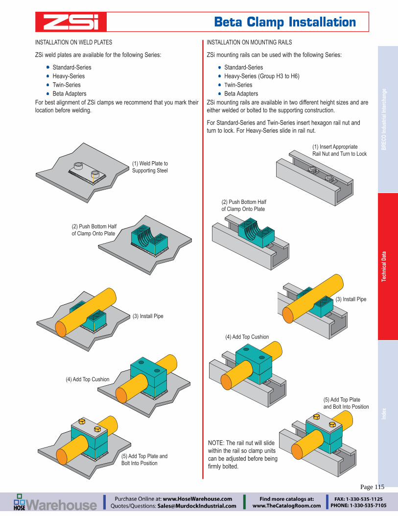
Inde
xTe
chni
cal D
ata
BREC
O In
dust
rial I
nter
chan
ge
Engineering Catalog www.zsi-inc.com – 115 –
INSTALLATION ON WELD PLATES
ZSi weld plates are available for the following Series:
Standard-Series Heavy-Series Twin-Series Beta Adapters
For best alignment of ZSi clamps we recommend that you mark their location before welding.
INSTALLATION ON MOUNTING RAILS
ZSi mounting rails can be used with the following Series:
Standard-Series
Twin-Series Beta Adapters
ZSi mounting rails are available in two different height sizes and are either welded or bolted to the supporting construction.
For Standard-Series and Twin-Series insert hexagon rail nut and turn to lock. For Heavy-Series slide in rail nut.
(1) Weld Plate toSupporting Steel
(2) Push Bottom Halfof Clamp Onto Plate
(3) Install Pipe
(4) Add Top Cushion
(5) Add Top Plate andBolt Into Position
(1) Insert AppropriateRail Nut and Turn to Lock
(2) Push Bottom Halfof Clamp Onto Plate
(3) Install Pipe
(4) Add Top Cushion
(5) Add Top Plateand Bolt Into Position
NOTE: The rail nut will slide within the rail so clamp units can be adjusted before being
Beta Clamp Installation
Page 115

– 116 – www.zsi-inc.com
MULTI-LEVEL ASSEMBLY
ZSi multi-level pipe clamps permit easy stacking of several tubes or pipes of the same group. The clamps are connected by stacking bolts.
Safety plates are inserted between the clamps to prevent the stack-ing bolts from turning.
The example below shows a stacking clamp added to a welded
plates, rails, or strut in the same manner.
INSTALLATION ON Z-STRUT CHANNEL
The Z-Strut Nuts can be used with any clamp using a 1/4-20 mounting bolt. This includes:
Standard-Series
Beta Rubber Inserts
(1) Insert Z-Strut NutsInto Z-Strut ChannelAnd Turn to Lock
(3) Install Pipe
(4) Add Top Cushion
(5) Add Top Plateand Bolt Into Position
(2) Push Bottom Halfof Clamp Onto Z-Strut Nuts
NOTE: The Z-Strut Nut will slide within the Z-Strut Chan-nel so clamp units can be
bolted.
(1) After the Top Cushion isAdded, Secure it with theStack Bolts
(2) Add Safety Plate toPrevent Stacking Boltsfrom Turning
(2) Assemble Another ClampOnto the Stacking Bolt inSame Manner as Single Clampsare Installed
Beta Clamp Installation
Page 116

Inde
xTe
chni
cal D
ata
BREC
O In
dust
rial I
nter
chan
ge
Engineering Catalog www.zsi-inc.com – 117 –
(5) Add Top Plateand Bolt into Position
(4) Add Top Cushion
Installation of Z-Clamps
Z-Clamps are installed in much the same manner as Beta Clamps. The weld studs are welded onto exiting structure and the clamp assembled onto them.
(1) Weld Studs toSupporting Steel
(2) Place the lower Z-ClampFrame Onto the Studs
(3) Attach the Stacking Bolts to the Frame and then Insert the Desired Adapters
(4) Bolt Top Frame Ontothe Bottom to Secure Assembly
Installation of Beta Adapter
Beta Adapters are installed in much the same manner as Beta Clamps. The weld plate is welded onto existing structure and the Beta cushion and adapter is assembled onto it.
(1) Weld Plate toSupporting Steel
(2) Push Bottom Halfof Clamp Onto Plate(3) Insert the Desired
Adapter
O-RING FACE SEALFEMALE JUNCTION ADAPTER
37° FLARE MALE JUNCTION ADAPTER
Z-CLAMP & BETA ADAPTER OPTIONAL ADAPTERS
RUBBER SPLIT BUSHINGSFEMALE JUNCTION
Beta Clamp Installation
Page 117

– 118 – www.zsi-inc.com
Standard Weight Pipe Data
Nom. Diameter (In.) Nom. Wt./Ft. (lbs.)
Length Containing One Cu. Ft.
Gallons / Linear Ft. (Gallons)Pipe Inside Outside
1 ⁄8 0.269 0.405 0.245 2,526.000 0.00301 ⁄4 0.364 0.540 0.425 1,383.800 0.00543 ⁄8 0.493 0.675 0.568 754.360 0.00991 ⁄2 0.622 0.840 0.851 473.910 0.01583 ⁄4 0.824 1.050 1.131 270.030 0.02771 1.049 1.315 1.679 166.620 0.0449
11 ⁄4 1.380 1.660 2.273 96.275 0.077711 ⁄2 1.610 1.900 2.718 70.733 0.10582 2.067 2.375 3.653 49.913 0.1743
21 ⁄2 2.469 2.875 5.793 30.077 0.24873 3.068 3.500 7.580 19.479 0.3840
31 ⁄2 3.548 4.000 9.110 14.565 0.51364 4.026 4.500 10.790 11.312 0.66135 5.047 5.563 14.620 7.198 1.03936 6.065 6.625 18.970 4.984 1.50088 7.981 8.625 28.550 2.878 2.5988
10 10.020 10.750 40.480 1.826 4.0963
Steel Pipe Data — Schedule No 40 & 80
Nominal Size (In.)
O.D. (In.)
Schedule No.
Wall Thick. (In.)
Weight. per Foot
(lbs)
Weight of Water
per Foot (lbs)3 ⁄8 0.675
40 0.091 0.567 0.08380 0.126 0.738 0.061
1 ⁄2 0.84040 0.109 0.850 0.13280 0.147 1.087 0.101
3 ⁄4 1.05040 0.113 1.130 0.23080 0.154 1.473 0.186
1 1.31540 0.133 1.678 0.37480 0.179 2.171 0.311
11 ⁄4 1.66040 0.140 2.272 0.64780 0.191 2.996 0.555
11 ⁄2 1.90040 0.145 2.717 0.88280 0.200 3.631 0.765
2 2.37540 0.154 3.652 1.45280 0.218 5.022 1.279
21 ⁄2 2.87540 0.203 5.790 2.07280 0.276 7.660 1.834
3 3.50040 0.216 7.570 3.20080 0.300 10.250 2.860
31 ⁄2 4.00040 0.226 9.110 4.28080 0.318 12.510 3.850
4 4.50040 0.237 10.790 5.51080 0.337 14.980 4.980
5 5.56340 0.258 14.620 8.66080 0.375 20.780 7.870
6 6.62540 0.280 18.970 12.51080 0.432 28.570 11.290
8 8.62540 0.322 28.550 21.60080 0.500 43.390 19.800
10 10.75040 0.365 40.480 34.10080 0.593 64.400 31.100
12 12.7540 0.406 53.600 48.50080 0.687 88.600 44.000
14 14.00040 0.437 63.000 58.50080 0.750 107.000 51.200
16 16.00040 0.500 83.000 76.50080 0.843 137.000 69.700
18 18.00040 0.563 105.000 97.20080 0.937 171.000 88.500
20 20.00040 0.593 123.000 120.40080 1.031 209.000 109.400
Copper Tube Data - Type L
Size (In.)
O.D. (In.)
O.D. (In.)
Wall Thick. (In.)
Weight per Foot (lbs)
Weight of Water / Ft. (lbs)
1 ⁄4 3 ⁄8 0.375 0.030 0.126 0.0343 ⁄8
1 ⁄2 0.500 0.035 0.198 0.0621 ⁄2 5 ⁄8 0.625 0.040 0.285 0.1005 ⁄8 3 ⁄4 0.750 0.042 0.362 0.1513 ⁄4 7 ⁄8 0.875 0.045 0.455 0.2091 11 ⁄8 1.125 0.050 0.655 0.357
11 ⁄4 13 ⁄8 1.375 0.055 0.884 0.54611 ⁄2 15 ⁄8 1.625 0.060 1.140 0.7672 21 ⁄8 2.125 0.070 1.750 1.341
21 ⁄2 25 ⁄8 2.625 0.080 2.480 2.0643 31 ⁄8 3.125 0.090 3.330 2.949
31 ⁄2 35 ⁄8 3.625 0.100 4.290 3.9894 41 ⁄8 4.125 0.110 5.380 5.1885 51 ⁄8 5.125 0.125 7.610 8.0816 61 ⁄8 6.125 0.140 10.200 11.6168 81 ⁄8 8.125 0.200 19.290 20.289
10 101 ⁄8 10.125 0.250 30.100 31.59012 121 ⁄8 12.125 0.280 40.400 45.426
Copper Tube Data - Type KSize (In.)
O.D. (In.)
O.D. (In.)
Wall Thick. (In.)
Weight per Foot (lbs)
Weight of Water / Ft. (lbs)
1 ⁄4 3 ⁄8 0.375 0.035 0.145 0.0323 ⁄8
1 ⁄2 0.500 0.049 0.269 0.0551 ⁄2 5 ⁄8 0.625 0.049 0.344 0.0945 ⁄8 3 ⁄4 0.750 0.049 0.418 0.1443 ⁄4 7 ⁄8 0.875 0.065 0.641 0.1881 11 ⁄8 1.125 0.065 0.839 0.337
11 ⁄4 13 ⁄8 1.375 0.065 1.040 0.52711 ⁄2 15 ⁄8 1.625 0.072 1.360 0.7432 21 ⁄8 2.125 0.083 2.060 1.310
21 ⁄2 25 ⁄8 2.625 0.095 2.920 2.0003 31 ⁄8 3.125 0.109 4.000 2.960
31 ⁄2 35 ⁄8 3.625 0.120 5.120 3.9004 41 ⁄8 4.125 0.134 6.510 5.0605 51 ⁄8 5.125 0.160 9.670 8.0006 61 ⁄8 6.125 0.192 13.870 11.2008 81 ⁄8 8.125 0.271 25.900 19.500
10 101 ⁄8 10.125 0.338 40.300 30.42312 121 ⁄8 12.125 0.405 57.800 43.675
Technical Data
Drill Sizes for NPT Pipe Taps
Tap Size (In.)
Threads/Inch
Drill Dia. (In.)
1 ⁄8 27 R1 ⁄4 18 7 ⁄16
3 ⁄8 18 37 ⁄64
1 ⁄2 14 23 ⁄32
3 ⁄4 14 59 ⁄64
1 111 ⁄2 15 ⁄32
11 ⁄4 111 ⁄2 11 ⁄211 ⁄2 111 ⁄2 147 ⁄64
2 111 ⁄2 27 ⁄32
21 ⁄2 8 25 ⁄83 8 31 ⁄4
31 ⁄2 8 33 ⁄44 8 41 ⁄4
Tap & Drill Sizes
Tap Size (In.)
Threads/Inch
Drill Size (In.)
1⁄4 20 75⁄16 18 F3⁄8 16 5⁄16
7⁄16 14 U1⁄2 13 27⁄64
9⁄16 12 31⁄645⁄8 11 17⁄323⁄4 10 21⁄327⁄8 9 49⁄64
1 8 7⁄811⁄8 7 63⁄64
11⁄4 7 17⁄64
13⁄8 6 17⁄32
11⁄2 6 111⁄32
13⁄4 5 19⁄16
2 41⁄2 125⁄32
Page 118
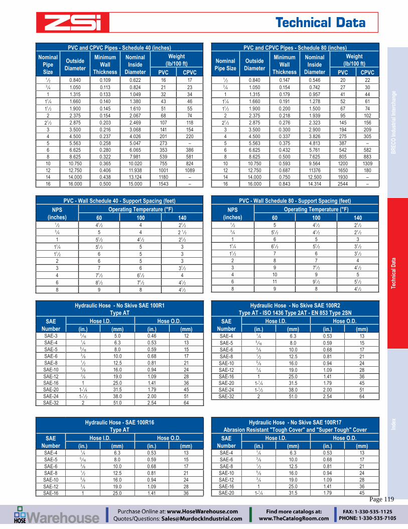
Inde
xTe
chni
cal D
ata
BREC
O In
dust
rial I
nter
chan
ge
Engineering Catalog www.zsi-inc.com – 119 –
Hydraulic Hose - No Skive SAE 100R1 Type AT
SAE Number
Hose I.D. Hose O.D.(in.) (mm) (in.) (mm)
SAE-3 3 ⁄16 5.0 0.46 12SAE-4 1 ⁄4 6.3 0.53 13SAE-5 5 ⁄16 8.0 0.59 15SAE-6 3 ⁄8 10.0 0.68 17SAE-8 1 ⁄2 12.5 0.81 21SAE-10 5 ⁄8 16.0 0.94 24SAE-12 3 ⁄4 19.0 1.09 28SAE-16 1 25.0 1.41 36SAE-20 1-1 ⁄4 31.5 1.79 45SAE-24 1-1 ⁄2 38.0 2.00 51SAE-32 2 51.0 2.54 64
Hydraulic Hose - No Skive SAE 100R2 Type AT - ISO 1436 Type 2AT - EN 853 Type 2SN
SAE Number
Hose I.D. Hose O.D.(in.) (mm) (in.) (mm)
SAE-4 1 ⁄4 6.3 0.53 13SAE-5 5 ⁄16 8.0 0.59 15SAE-6 3 ⁄8 10.0 0.68 17SAE-8 1 ⁄2 12.5 0.81 21SAE-10 5 ⁄8 16.0 0.94 24SAE-12 3 ⁄4 19.0 1.09 28SAE-16 1 25.0 1.41 36SAE-20 1-1 ⁄4 31.5 1.79 45SAE-24 1-1 ⁄2 38.0 2.00 51SAE-32 2 51.0 2.54 64
Hydraulic Hose - SAE 100R16 Type AT
SAE Number
Hose I.D. Hose O.D.(in.) (mm) (in.) (mm)
SAE-4 1 ⁄4 6.3 0.53 13SAE-5 5 ⁄16 8.0 0.59 15SAE-6 3 ⁄8 10.0 0.68 17SAE-8 1 ⁄2 12.5 0.81 21SAE-10 5 ⁄8 16.0 0.94 24SAE-12 3 ⁄4 19.0 1.09 28SAE-16 1 25.0 1.41 36
Hydraulic Hose - No Skive SAE 100R17 Abrasion Resistant "Tough Cover" and "Super Tough" Cover
SAE Number
Hose I.D. Hose O.D.(in.) (mm) (in.) (mm)
SAE-4 1 ⁄4 6.3 0.53 13SAE-6 3 ⁄8 10.0 0.68 17SAE-8 1 ⁄2 12.5 0.81 21SAE-10 5 ⁄8 16.0 0.94 24SAE-12 3 ⁄4 19.0 1.09 28SAE-16 1 25.0 1.41 36SAE-20 1-1 ⁄4 31.5 1.79 45
PVC and CPVC Pipes - Schedule 40 (inches)
Nominal Pipe Size
Outside Diameter
Minimum Wall
Thickness
Nominal Inside
Diameter
Weight (lb/100 ft)
PVC CPVC1 ⁄2 0.840 0.109 0.622 16 173 ⁄4 1.050 0.113 0.824 21 231 1.315 0.133 1.049 32 34
11 ⁄4 1.660 0.140 1.380 43 4611 ⁄2 1.900 0.145 1.610 51 552 2.375 0.154 2.067 68 74
21 ⁄2 2.875 0.203 2.469 107 1183 3.500 0.216 3.068 141 1544 4.500 0.237 4.026 201 2205 5.563 0.258 5.047 273 –6 6.625 0.280 6.065 353 3868 8.625 0.322 7.981 539 58110 10.750 0.365 10.020 755 82412 12.750 0.406 11.938 1001 108914 14.000 0.438 13.124 1180 –16 16.000 0.500 15.000 1543 –
PVC and CPVC Pipes - Schedule 80 (inches)
Nominal Pipe Size
Outside Diameter
Minimum Wall
Thickness
Nominal Inside
Diameter
Weight (lb/100 ft)
PVC CPVC1 ⁄2 0.840 0.147 0.546 20 223 ⁄4 1.050 0.154 0.742 27 301 1.315 0.179 0.957 41 44
11 ⁄4 1.660 0.191 1.278 52 6111 ⁄2 1.900 0.200 1.500 67 742 2.375 0.218 1.939 95 102
21 ⁄2 2.875 0.276 2.323 145 1563 3.500 0.300 2.900 194 2094 4.500 0.337 3.826 275 3055 5.563 0.375 4.813 387 –6 6.625 0.432 5.761 542 5828 8.625 0.500 7.625 805 88310 10.750 0.593 9.564 1200 130912 12.750 0.687 11376 1650 18014 14.000 0.750 12.500 1930 –16 16.000 0.843 14.314 2544 –
PVC - Wall Schedule 40 - Support Spacing (feet)
NPS (inches)
Operating Temperature (°F)60 100 140
1 ⁄2 41 ⁄2 4 21 ⁄2 3 ⁄4 5 4 2 1 ⁄2 1 51 ⁄2 41 ⁄2 21 ⁄2
11 ⁄4 51 ⁄2 5 311 ⁄2 6 5 32 6 5 33 7 6 31 ⁄2 4 71 ⁄2 61 ⁄2 46 81 ⁄2 71 ⁄2 41 ⁄2 8 9 8 41 ⁄2
PVC - Wall Schedule 80 - Support Spacing (feet)
NPS (inches)
Operating Temperature (°F)60 100 140
1 ⁄2 5 41 ⁄2 21 ⁄2 3 ⁄4 51 ⁄2 41 ⁄2 21 ⁄2 1 6 5 3
11 ⁄4 61 ⁄2 51 ⁄2 31 ⁄2 11 ⁄2 7 6 31 ⁄2 2 8 7 43 9 71 ⁄2 41 ⁄2 4 10 9 56 11 91 ⁄2 51 ⁄2 8 9 8 41 ⁄2
Technical Data
Page 119
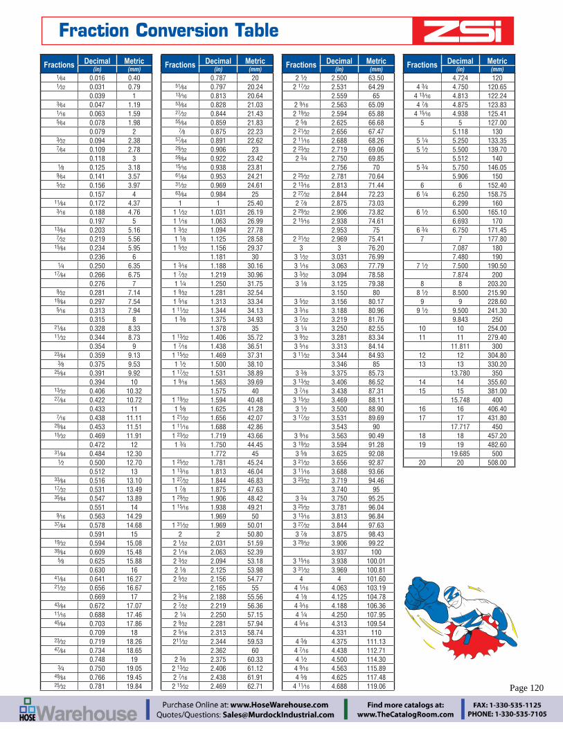
– 120 – www.zsi-inc.com
Fractions Decimal Metric(in) (mm)
1⁄64 0.016 0.40 1⁄32 0.031 0.79
0.039 1 3⁄64 0.047 1.19 1⁄16 0.063 1.59 5⁄64 0.078 1.98
0.079 2 3⁄32 0.094 2.38 7⁄64 0.109 2.78
0.118 3 1⁄8 0.125 3.18 9⁄64 0.141 3.57 5⁄32 0.156 3.97
0.157 4 11⁄64 0.172 4.37 3⁄16 0.188 4.76
0.197 5 13⁄64 0.203 5.16 7⁄32 0.219 5.56 15⁄64 0.234 5.95
0.236 6 1⁄4 0.250 6.35 17⁄64 0.266 6.75
0.276 7 9⁄32 0.281 7.14 19⁄64 0.297 7.54 5⁄16 0.313 7.94
0.315 8 21⁄64 0.328 8.33 11⁄32 0.344 8.73
0.354 9 23⁄64 0.359 9.13 3⁄8 0.375 9.53 25⁄64 0.391 9.92
0.394 10 13⁄32 0.406 10.32 27⁄64 0.422 10.72
0.433 11 7⁄16 0.438 11.11 29⁄64 0.453 11.51 15⁄32 0.469 11.91
0.472 12 31⁄64 0.484 12.30 1⁄2 0.500 12.70
0.512 13 33⁄64 0.516 13.10 17⁄32 0.531 13.49 35⁄64 0.547 13.89
0.551 14 9⁄16 0.563 14.29 37⁄64 0.578 14.68
0.591 15 19⁄32 0.594 15.08 39⁄64 0.609 15.48 5⁄8 0.625 15.88
0.630 16 41⁄64 0.641 16.27 21⁄32 0.656 16.67
0.669 17 43⁄64 0.672 17.07 11⁄16 0.688 17.46 45⁄64 0.703 17.86
0.709 18 23⁄32 0.719 18.26 47⁄64 0.734 18.65
0.748 19 3⁄4 0.750 19.05 49⁄64 0.766 19.45 25⁄32 0.781 19.84
Fractions Decimal Metric(in) (mm)
0.787 20 51⁄64 0.797 20.24 13⁄16 0.813 20.64 53⁄64 0.828 21.03 27⁄32 0.844 21.43 55⁄64 0.859 21.83 7⁄8 0.875 22.23 57⁄64 0.891 22.62 29⁄32 0.906 23 59⁄64 0.922 23.42 15⁄16 0.938 23.81 61⁄64 0.953 24.21 31⁄32 0.969 24.61 63⁄64 0.984 25
1 1 25.401 1⁄32 1.031 26.191 1⁄16 1.063 26.991 3⁄32 1.094 27.781 1⁄8 1.125 28.581 5⁄32 1.156 29.37
1.181 301 3⁄16 1.188 30.161 7⁄32 1.219 30.961 1⁄4 1.250 31.751 9⁄32 1.281 32.541 5⁄16 1.313 33.341 11⁄32 1.344 34.131 3⁄8 1.375 34.93
1.378 351 13⁄32 1.406 35.721 7⁄16 1.438 36.511 15⁄32 1.469 37.311 1⁄2 1.500 38.10
1 17⁄32 1.531 38.891 9⁄16 1.563 39.69
1.575 401 19⁄32 1.594 40.481 5⁄8 1.625 41.28
1 21⁄32 1.656 42.071 11⁄16 1.688 42.861 23⁄32 1.719 43.661 3⁄4 1.750 44.45
1.772 451 25⁄32 1.781 45.241 13⁄16 1.813 46.041 27⁄32 1.844 46.831 7⁄8 1.875 47.63
1 29⁄32 1.906 48.421 15⁄16 1.938 49.21
1.969 501 31⁄32 1.969 50.01
2 2 50.802 1⁄32 2.031 51.592 1⁄16 2.063 52.392 3⁄32 2.094 53.182 1⁄8 2.125 53.982 5⁄32 2.156 54.77
2.165 552 3⁄16 2.188 55.562 7⁄32 2.219 56.362 1⁄4 2.250 57.152 9⁄32 2.281 57.942 5⁄16 2.313 58.74211⁄32 2.344 59.53
2.362 602 3⁄8 2.375 60.33
2 13⁄32 2.406 61.122 7⁄16 2.438 61.912 15⁄32 2.469 62.71
Fractions Decimal Metric(in) (mm)
2 1⁄2 2.500 63.502 17⁄32 2.531 64.29
2.559 652 9⁄16 2.563 65.092 19⁄32 2.594 65.882 5⁄8 2.625 66.68
2 21⁄32 2.656 67.472 11⁄16 2.688 68.262 23⁄32 2.719 69.062 3⁄4 2.750 69.85
2.756 702 25⁄32 2.781 70.642 13⁄16 2.813 71.442 27⁄32 2.844 72.232 7⁄8 2.875 73.03
2 29⁄32 2.906 73.822 15⁄16 2.938 74.61
2.953 752 31⁄32 2.969 75.41
3 3 76.203 1⁄32 3.031 76.993 1⁄16 3.063 77.793 3⁄32 3.094 78.583 1⁄8 3.125 79.38
3.150 803 5⁄32 3.156 80.173 3⁄16 3.188 80.963 7⁄32 3.219 81.763 1⁄4 3.250 82.553 9⁄32 3.281 83.343 5⁄16 3.313 84.143 11⁄32 3.344 84.93
3.346 853 3⁄8 3.375 85.73
3 13⁄32 3.406 86.523 7⁄16 3.438 87.313 15⁄32 3.469 88.113 1⁄2 3.500 88.90
3 17⁄32 3.531 89.693.543 90
3 9⁄16 3.563 90.493 19⁄32 3.594 91.283 5⁄8 3.625 92.08
3 21⁄32 3.656 92.873 11⁄16 3.688 93.663 23⁄32 3.719 94.46
3.740 953 3⁄4 3.750 95.25
3 25⁄32 3.781 96.043 13⁄16 3.813 96.843 27⁄32 3.844 97.633 7⁄8 3.875 98.43
3 29⁄32 3.906 99.223.937 100
3 15⁄16 3.938 100.013 31⁄32 3.969 100.81
4 4 101.604 1⁄16 4.063 103.194 1⁄8 4.125 104.784 3⁄16 4.188 106.364 1⁄4 4.250 107.954 5⁄16 4.313 109.54
4.331 1104 3⁄8 4.375 111.134 7⁄16 4.438 112.714 1⁄2 4.500 114.304 9⁄16 4.563 115.894 5⁄8 4.625 117.48
4 11⁄16 4.688 119.06
Fractions Decimal Metric(in) (mm)
4.724 1204 3⁄4 4.750 120.65
4 13⁄16 4.813 122.244 7⁄8 4.875 123.83
4 15⁄16 4.938 125.415 5 127.00
5.118 1305 1⁄4 5.250 133.355 1⁄2 5.500 139.70
5.512 1405 3⁄4 5.750 146.05
5.906 1506 6 152.40
6 1⁄4 6.250 158.756.299 160
6 1⁄2 6.500 165.106.693 170
6 3⁄4 6.750 171.457 7 177.80
7.087 1807.480 190
7 1⁄2 7.500 190.507.874 200
8 8 203.208 1⁄2 8.500 215.90
9 9 228.609 1⁄2 9.500 241.30
9.843 25010 10 254.0011 11 279.40
11.811 30012 12 304.8013 13 330.20
13.780 35014 14 355.6015 15 381.00
15.748 40016 16 406.4017 17 431.80
17.717 45018 18 457.2019 19 482.60
19.685 50020 20 508.00
Fraction Conversion Table
Page 120

Inde
xTe
chni
cal D
ata
BREC
O In
dust
rial I
nter
chan
ge
Engineering Catalog www.zsi-inc.com – 121 –
Part No. ...................Page Part No. ...................Page Part No. ...................Page Part No. ...................Page
190.............................88
1164...........................89
1900...........................88
3017...........................91
6124...........................91
301804.......................89
301805.......................91
301820.......................91
004M ..........................10
004N ............................6
004T .............................6
006C ..........................12
006M ..........................10
006N ............................6
006T .............................6
008C ..........................12
008M ..........................10
008N ............................6
008T .............................6
009N ............................6
010C ..........................12
010M ..........................10
010N ............................6
010T .............................6
011N ............................6
012C ..........................12
012M ..........................10
012N ............................6
012T .............................6
014C ..........................12
014M ..........................10
014N ............................6
014T .............................6
016C ..........................12
016M ..........................10
016N ............................6
016T .............................6
017N ............................6
018C ..........................12
018M ..........................10
018N ............................6
018T .............................6
020C ..........................12
020M ..........................10
020N ............................6
020T .............................6
021M ..........................10
021N ............................6
022C ..........................12
022M ..........................10
022N ............................6
022T .............................6
024C ..........................12
024M ..........................10
024N ............................6
026C ..........................12
026M ..........................10
026N ............................6
027M ..........................10
027N ............................6
028C ..........................12
028M ..........................10
028N ............................6
030C ..........................12
030M ..........................10
030N ............................6
032C ..........................12
032M ..........................10
032N ............................6
034C ..........................12
034M ..........................10
034N ............................6
036C ..........................12
038M ..........................10
038N ............................6
040C ..........................12
040M ..........................10
040N ............................6
042C ..........................12
042M ..........................10
042N ............................6
044C ..........................12
046C ..........................12
046M ..........................10
046N ............................6
048C ..........................12
050C ..........................12
050M ..........................10
050N ............................6
052C ..........................12
053N ............................6
054C ..........................12
056C ..........................12
056M ..........................10
056N ............................6
058C ..........................12
058M ..........................10
058N ............................6
060C ..........................12
064C ..........................12
064M ..........................10
064N ............................6
066C ..........................12
066M ..........................10
066N ............................6
068C ..........................12
069N ............................6
070C ..........................12
072M ..........................10
072N ............................6
082M ..........................10
082N ............................6
089M ..........................10
089N ............................6
096N ............................6
098M ..........................10
098N ............................6
106M ..........................10
106N ............................6
1DS.............................72
1ST .............................78
2DS.............................72
2ST .............................78
3DS.............................72
3ST .............................78
4DS.............................72
4ST .............................78
6DS.............................72
6ST .............................78
8DS.............................72
8ST .............................78
AC ..............................55
AC4 ............................90
AD ..............................86
AR...............................55
AS ..............................55
AV ...............................55
B-11 ............................87
B-13 ............................87
B-15 ............................87
Part Number Index
Page 121

– 122 – www.zsi-inc.com
B-18 ............................85
B-2B ............................59
B-2CE ..........................61
B-2CF ..........................60
B-2CG .........................61
B-2CH .........................61
B-2CK ..........................61
B-2CM .........................61
B-2CP ..........................61
B-2CS ..........................61
B-2J .............................66
B-2L .............................67
B-2O ...........................68
B-2TL ...........................70
B-2U ............................69
B-2W ..........................77
B-30 ............................77
B-324 ..........................85
B-37 ............................86
B-3B ............................59
B-3CF ..........................60
B-3CM .........................61
B-3CP ..........................61
B-3CS ..........................61
B-3F ............................75
B-3J .............................66
B-3O ...........................68
B-3W ..........................77
B-40 ............................73
B-41 ............................73
B-4B ............................59
B-4C .......................60,66
B-4FF ...........................75
B-4T ............................70
B-50 ............................87
B-52 ............................73
B-54 ............................87
B-55 ............................87
B-56 ............................87
B-61 ............................74
B-66 ............................76
B-6B ............................59
B-6F ............................75
B-74 ............................83
B-80 ............................73
B-8F ............................75
B-B2 ............................65
B-B3 ............................65
B-B4 .......................65,66
B-B6 ............................65
B-BP .............................82
B-FF .............................75
B-J ...............................66
B-L ...............................67
B-O .............................68
B-PC ............................82
B-PH ............................80
B-PN .......................81,82
B-TL .............................70
B-VHC .........................80
B-VHN .........................80
B-W2 ..........................77
B-W3 ..........................77
BG .........................89,90
BH1 to BH8 .................72
C-1 to C-4 ....................85
CBN ............................26
CBS .............................27
CBS12EX .....................29
CBS16EX .....................29
CBS1D ........................28
CBS1DS.......................31
CBS1PRB .....................31
CBS1RB .......................30
CBS1RD .......................28
CBS1S .........................28
CBS28BR .....................29
CBS2D ........................28
CBS2DS.......................31
CBS2PRB .....................31
CBS2RB .......................30
CBS2RD .......................28
CBS2S .........................28
CBS36BR .....................29
CBS3D ........................28
CBS3DS.......................31
CBS3PRB .....................31
CBS3RB .......................30
CBS3RD .......................28
CBS3S .........................28
CBS42BR .....................29
CBS4D ........................28
CBS4DS.......................31
CBS4PRB .....................31
CBS4RB .......................30
CBS4RD .......................28
CBS4S .........................28
CBS50BR .....................29
CBS60BR .....................29
CBS8EX .......................29
CC1 ............................19
CC2 ............................19
CC3 ............................25
CC5 ............................25
CG ................................8
CL .................................7
CLS ...............................7
CS ................................9
CWP ...........................18
CWT ...........................18
D320 ..........................60
D321 ..........................61
D340 ..........................60
D341 ..........................61
D342 ..........................61
D344 ..........................61
D352 ..........................61
D360 ..........................60
D361 ..........................61
D362 ..........................61
D364 ..........................61
D440 ..........................60
D441 ..........................61
D442 ..........................61
D452 ..........................61
D460 ..........................60
D461 ..........................61
D462 ..........................61
D464 ..........................61
D480 ..........................60
D481 ..........................61
D482 ..........................61
D484 ..........................61
D5120 ........................60
D5121 ........................61
D5122 ........................61
D540 ..........................60
D541 ..........................61
D542 ..........................61
D560 ..........................60
D561 ..........................61
D562 ..........................61
D580 ..........................60
D581 ..........................61
Part No. ...................Page Part No. ...................Page Part No. ...................Page Part No. ...................Page
Part Number Index
Page 122

Inde
xTe
chni
cal D
ata
BREC
O In
dust
rial I
nter
chan
ge
Engineering Catalog www.zsi-inc.com – 123 –
D582 ..........................61
D584 ..........................61
DC-1 to DC-3 ...............88
DCP ............................41
DCPOLY .......................92
DS...............................72
DW .............................69
EMT ..............................7
FJA ..............................53
FPE ..............................85
G-1 to G-3 ...................53
H-3 to H-9 ....................40
H30 ............................41
H40 ............................46
H4C ............................46
H4F .............................47
H4J .............................47
H4M ...........................47
H50 ............................46
H5C ............................46
H5FJ ............................47
H5J .............................47
H5M ...........................47
H60 ............................46
H6C ............................46
H70 ............................46
H7C ............................46
H80 ............................46
H8C ............................46
HAC .......................49,50
HB-1 ............................51
HB-3 ............................51
HBF .............................84
HBM ...........................84
HCP ............................41
HCR ............................41
HDP ............................41
HHB ............................41
HM .............................46
HRN ............................41
HS ..............................84
HSB .............................41
HSN ............................21
HSP .............................41
HVN ...........................21
HW .............................51
HWP ...........................41
HWP1 to HWP8 ...........17
HWT ...........................17
LVZ ..............................25
MAN ...........................91
MF ..............................91
MJA ............................52
MJO ............................52
N-1 to N-6 ...................86
N0 ................................9
N1 ................................9
NS ................................9
P3 ...............................65
P4 ...............................65
P5 ...............................65
PC ...............................82
PDC ............................75
POF .............................84
POM ...........................84
POS ............................84
PRB .............................86
PT ...............................85
PY ...............................32
QC .............................19
RPC ...............................8
S-1 ..............................51
S-10 ............................38
S-2 ..............................51
S-2004H ......................44
S-2006H ......................44
S-2008 ........................38
S-2009 to S-2011 .........38
S-3 ..............................51
S-3008H ......................44
S-3010H ......................44
S-3012 to S4018 .........38
S-4012H ......................44
S-5016H ......................44
S-5020 to S-6032 .........38
S-70 ............................38
S1004-C ......................39
S40 .............................45
S4C ............................45
S60 .............................45
S6C ............................45
SB ...............................39
SC ..............................39
SCP .............................39
SCR .............................43
SD...............................13
SDC ............................75
SE45 ...........................85
SE90 ...........................85
SHB .............................39
SHP .............................86
SM ..............................38
SM4 ............................45
SM6 ............................45
SP ...............................39
SPD .............................21
SPH .............................22
SPN ............................20
SPP .............................23
SPW ............................20
SRN .......................39,43
SSN ............................25
ST ...............................78
SV ...............................64
SVN ............................24
SVPC ...........................64
SVW ...........................24
SWP ............................39
T-1...............................51
T-10.............................42
T-20.............................44
T-3...............................51
T-30 to T-50 ..................44
T20 .............................43
TB ...............................43
TC ...............................43
TP ...............................43
TRN .............................43
TSB .............................43
TSP ..............................43
UB ..............................11
UX ..............................14
W-1 to W-3 .................51
Z10 .............................39
Z16 .............................39
Z81 .............................39
Z87 .............................39
ZSA .............................39
Part No. ...................Page Part No. ...................Page Part No. ...................Page Part No. ...................Page
Part Number Index
Page 123

© Copyright 2012 ZSi All Rights reserved / Printed & Designed in the USA / HP / 10M / 8.12
ZSi World Headquarters 45065
Page 124