zx-a10 cable fault tester manual-gdzx
TRANSCRIPT

ZX-A10 Cable Fault Tester

- 1 -
CatalogueChapter Ⅰ Functions introduction........................................................................................- 4 -
2.Introduction of panel.............................................................................................- 6 -
Chapter II software introduction.....................................................................................- 8 -
1. Host........................................................................................................................ - 8 -
2.Introduction of test system control panel..........................................................- 8 -
Chapter III Test procedure of......................................................................................... - 13 -
Chapter IV Introduction of test method........................................................................- 14 -
1. Test theory...........................................................................................................- 14 -
2. Low voltage pulse method....................................................................................- 14 -
3. Impulse flash-over current method.................................................................- 20 -
The sixth section introduces the pathfinder.................................................................... - 26 -
Synopsis.............................................................................................................................- 26 -
I. basic composition and main purpose............................................................................- 27 -
Ii. Technical indicators....................................................................................................... - 27 -
Iii. Operation instructions................................................................................................. - 28 -
Routing detection..............................................................................................................- 32 -
V. matters needing attention............................................................................................ - 33 -
Complete sets of instruments...........................................................................................- 34 -
Section 7 introduction of fixed point instrument.............................................................- 34 -
I. overall overview............................................................................................................. - 34 -
Ii. Technical features..........................................................................................................- 35 -
Iii. Technical parameters................................................................................................... - 35 -

- 2 -
1. Standard configuration......................................................................................... - 35 -
2. receiver host connection and control.................................................................. - 36 -
Iv. Site installation and operation..................................................................................... - 36 -
1. Connect the sensor to a suitable probe or probe................................................ - 36 -
2. Connect the sensor with the handle.................................................................... - 37 -
3. Adjust the height of the handle............................................................................- 37 -
4. Connect the sensor and headset with the receiver host.....................................- 38 -
5. receiver host......................................................................................................... - 38 -
5.1 opening of receiver host.............................................................................- 38 -
5.2 self-test of battery power...........................................................................- 38 -
5.3 one-button fit knob.................................................................................... - 38 -
5.4 display of measurement interface............................................................. - 39 -
5. Starting to use cable fault precise locating instrument............................................... - 39 -
1.1 precise fixed-point operation procedures..........................................................- 40 -
1.2 shutdown............................................................................................................ - 40 -

- 3 -
Notice: Thank you for selecting our product. This device is highly integrated
precise instrument with same function of notebook. Do not use to surf on
internet if without testing cable fault, to avoid virus and bring inconvenience to
your test work and equipment maintenance . We suggest you to arrange
professional person operate and keep. Please charge regularly once a month.
Do not open host chassis if not professional.
Warning:
When test power cable's high resistance fault , by taking impulse flash
method the fault point should be discharged and have an open flame . Please
note that it is strictly prohibited to test in high gas, high concentration flammable
gas environment.In case of safety accident cause by wrong use, the equipment
manufacturer has nothing to do with it!

- 4 -
ChapterⅠ Functions introductionElectric cable faults testing device is networking cable fault test platform based
on embedded computer platform. It is integrated USB communication technology,touch-screen technology and 3G communication technology and this greatly improvedthe performance of the instrument in practice and is easy to operate.
This device provides you a specified cable management software to reduceyour workload. The whole system meet the requirements of general technicalconditions for testing equipment "DL/T849.1 ~ DL/T849.3-2004", Electric PowerIndustry Standards of the Peoples’ Republic of China.
The test system is composed three parts: a host computer system ,path tracerand cable fault locator . It is mainly used for testing all kinds of power cable fault, cableroute, cable burial depth and daily management and maintenance of cable data. It canalso be used for accurate testing of railway and airport signal control cable fault andstreetlight cable fault.
◆Adopts embedded industrial computer platform, Industrial grade using
environment,high stability. Lithium electricity power supply, convenient for site test.
◆12.1 inch large screen system,touch mouse operation,Computer XP operating
platform integrated software.
◆Adopts the latest USB communication interface,signal collecting stability, can
realize double control and double display by use with a notebook computer, The host
can automatically select five kinds of sampling frequency from 6.25MHz to 100MHz,
adaptive pulse width can meet the testing requirements of different cable lengths to
reduce the rough measurement error and improve test accuracy.
◆Software realize searching fault automatically , display distance automatically ,
double vernier movement which can be accurate to 0.15 m. Waveform can be freely
compressed and extended,two waveforms closer to the standard displaying in one
screen for you to accurately compare and analyze, improve test accuracy and reduce

- 5 -
error.
◆The host can equip with WIFI receiver and 3G software to get remote on-site test
help and suggestions from our experts. Technicians can help on-site testing through
android testing software at any time and anywhere.
◆ 8G memory multiple kinds of field waveform and field wiring diagram,can be
used with a tap.
◆Precise locator can directly display the distance from tester to fault point. We use
squelch technology which is another innovation of domestic similar products. It helps
you in locating fault precisely and quickly and also helps your reduce damage and loss
arising from power off.
◆The newly developed intelligent combined sampler has replaced the tedious field
connection. It has the features of intuitive waveform, easy analysis, complete isolation
from the high voltage, and absolute safety for the main engine and operators.
Test parameters
Can test cable fault at different voltage levels. Can test cable fault of different cablesections, different dielectric and different cable materials. Can test open-circuit cablefault, short-circuit cable fault, low-resistance cable fault, high-resistance leakage cablefault and high-resistance flash-over cable fault.
1) Can test all faults of railway communication control cable, streetlight cable andairport signal cable.
2) Can test wave transmitting velocity in any cable of known length.3) Can test buried route and depth of power cable.
Test distance: no less than 60Km
Min. test distance (non-detection area): 0-5m or without
Locating error: ±0.2m

- 6 -
Test error: system error is no ore than ±1%
*Resolution: V/fm,V is transmitting velocity m/μs;software cursor is 0.15m.
Sampling frequency: 6.25MHz,12.5MHz,25MHz,50MHz,100MHz (Adaptive pulse
width).
Power source and power consumption: AC 220V±10%, power consumption≤15W
DC 12V(7AH), power consumption≤20W
Standby time: continuous working 4 hours
2.Introduction of panelpanel is as follow drawing, please select corresponding output end and switch
according to test requirement.
1) Power adapter: AC220V, 50Hz , a full charge require 6 hours .
2) Indicating lightPower indication : Monochromatic diode , red light is always on when instrument
work normally.
Under-voltage indication: Red diode light is on and alarm ring when

- 7 -
under-voltage.
If the host displays under-voltage, please shut down the device and charging by220V adapter . After 30 seconds, you can restart the device.
Low voltage pulse indication: Green diode light is on after start, work statue is
pulse method testing.
Impulse flash-over indication: Red diode, red light is on when working statue isin multiple pulse sampling position.
3) Output socket: BNC-50KY(Q9) plug for signal output.
4) Output amplitude: This is used for adjusting input and output pulse amplitudeaccording to waveform displayed in LCD. If adjustment is not enough, reflection pulsewill be very small even can not be sampled( as shown in Fig.3). If over adjust, reflectionpulse wont intersect with baseline even baseline will be a oblique line(as shown inFig.4). Usually, adjust amplitude button to 1/3, then adjust again according to samplingwaveform or re-sample.
5) Switch: Press to start system and enter working interface. Please shutdownaccording to Windows XP tips. Do not shutdown system by this button.
6) Display Screen: 12.1in. LCD with touch screen system. It is strictly forbidden tooverpressure the non-touch system by hand,operate by touch mouse on the lower rightcorner,forbidden to put heavy object on screen or squeeze it.
7) Reset: Refresh main board program. Press this button after start, pulseindication light will flash one time and test program is in working statue. Please exitsystem and press refresh button to refresh program once there is a port error hint andre-enter test program.
8) USB: Can send waveform and date to computer to analyze, store and print.

- 8 -
Can use wireless network card to connect to internet.9) Touch-control mouse: same to normal mouse for system operation.
Chapter II software introduction
1. Host1) Click on cable test iconic on desktop, screen display as figure as below ..
2) Shutdown windows first, then shut down power supply. Do not shutdown powersupply when test system is in operating or shutdown system frequently.
3) Please connect lithium battery charger if host is under voltage. Red light will beon while charging and it will turn to green after fully charge.
Main interface of testing software
2.Introduction of test system control panelPress “cable fault test”button to enter into testing panel. Testing panel is divided into 4
parts: menu bar, status bar, waveform display area and functional buttons.

- 9 -
Test system interface two-screen diagram
Test system interface single screen diagram
The upper part of the graphic display area is the real-time waveform, and the lower partis the manual analysis area.
Double-click the above waveform to load the manual analysis area.Red label is single

- 10 -
and double screen displayconversion button.
(1) Menu barmenu bar includes two menus"file” menu: includes "Open file", "save file" two menu.select "open file",read out the waveform saved before,select"save file",save the waveform and test data,"testing report",the contents display on the screen will be formed into a "cable fault
testing report" .select "print" or"close" button to finish job you want to do.Choose "Store",test waveform and data can
be stored on the computer'shard disk or floppy disk,for data preservation.
(2)Status barStatus bar includes 5 parts: test method,frequency,wave speed,fault,time. All of
these information will be displayed automatically in "Automatic waveform area" and"manual waveform area" according to your selection.
(3)Waveform display areaThis area will display sampled waveform. It is divided into“ automatic waveform
area” and “manual waveform area”. The "automatic waveform area" automaticallyoptimizes a waveform during testing,when use low voltage pulse method to test ,it willbe clip position automatically and calculate the fault distance automatically, the currentsampling test method has no such function.
Select a waveform in the "automatic waveform area" and click on it ,and it willappear a waveform immediately in the "manual waveform area" where you can analyze,process and clip position.The blue cursor line is the start location cursor, green cursor isthe fault screens cursor,Click the mouse to the inflection point, the cursor on the point,the distance immediately out.The fault distance is shown directly in the small grid of thecursor line.
(4)Functional buttonsFunctional buttons area is in the bottom of screen and composed by 8 buttons,
function of 8 buttons as below :

- 11 -
◆Test setting”:Using when system testing. Select “test method”,“cable
length/frequency”,“cable type/wave speed”according to tested cable. Window menu
includes two sub-menus: “fault test ” and “speed test”. Each menu item tocorrespond to a test method. You need to input cable full length if you test velocity.
Testing software interface
“Test method”menu includes 2 sub-menus: “LV pulse method(TDR)”,and “Impulse HV
flash-over method(ICM)”.“cable length/frequency”corresponds to the following five types: you only need to
choose a approximate lengthaccording to the length of tested cable , and choose corresponding sampling frequency
at the same time, so that thesampling automatically adapted to pulse width, the resulting waveform is more standard
and the inflection point ismore clear.
shown as below:
Optional approximate length range as below:●5m<L<615 m Sampling frequency 100MHz

- 12 -
●615m<L<1229 m Sampling frequency 50MHz
●1229m<L<2458 m Sampling frequency 25MHz
●2458<L<4915 m Sampling frequency 10MHz
●4915m<L<50000m Sampling frequency 6.25MHz
“cable type/wave speed”included :●Oil-paper: V=160m/μS●Non-drop: V=144m/μS●Cross-linked polyethylene:V=172m/μS●PVC :V=184m/μS●Optional medium: V=***m/μSFive menu items, choose one menu equals to choose one speed. Add medium
according to user's special cable.If the wave speed tested not included in above,please input wave velocity of the selected medium by clicking # at the bottom left ofthe test software interface (the instrument has been set for you when leaving thefactory),input the selected wave velocity.
◆ “Single/more” button: Single means sample one time to get 1 waveform,
continuous means sample one time to get continuous waveform.
◆“Synchronization(sync)”button: When you need to compare two waveform
to analysis, click this button then two waveform will be back initial end in same scale.
◆“Sample” button: Press this button one time to get one sample and will draw
waveform in display area.
◆“Zoom+/Zoom-(automatic area )”shrink” button: Stretch or shrink waveform
to get a full view to help you analysis and locate fault point. Click one time to
stretch/shrink waveform one time.
◆“Zoom+/Zoom-(manual area )” button: Stretch or shrink waveform to get a
full view to help you analysis and locate fault point. Click one time to stretch/shrink
waveform one time.
◆“<<cursor” button: This button is used to fine-tuning blue/green cursor to left.

- 13 -
◆“cursor>>” button: This button is used to fine-tuning blue/green cursor to right.
◆ “Exit”: Exit system.
Chapter III Test procedure ofPlease follow procedures below to resolve cable fault quickly:1. Analyze nature of cable fault and cable type.
Different cable type is tested by different method, different cable medium has
different testing velocity, different cable has different voltage-resistant level. You need to
know these information before test.2.Test cable full length by and proofread wave velocity by LV impulse method.
Test full length of cable can help us to understand cable fault clearly and judge
nature of cable fault (high impedance fault or low impedance fault). Meantime we can
calculate wave velocity to make accurate test.3. Choose proper test method, make rough test by cable fault locate host.
Different test method is for different cable fault. Low impedance fault (open-circuit
or short circuit) is tested by LV impulse method, high impedance fault (leakage or
flash-over) is tested by multiple pulse method or impulse HV flash-over method.
Choose proper method test cable full length and fault approximate position.
Faultnature
InsulationResistance
Breakdown situation
Open circuit reak-down by DC or high voltage impulse
Lowresistance
less-than
10ZCan be break-down by high voltage impulse ifresistance is not very low
Highresistance
more-than
10Zigh-voltage pulse breakdown
flashover reak-down by DC or high voltage impulse
Remark: Zo is characteristic impedance value. For electric cable it is usually
between 10—40.
Low voltage flash-over method is simple, can be tested directly . You should pay

- 14 -
attention to the wire connection and the DC high voltage added when you use highvoltage flash-over method. The maximum voltage withstanding for oil paper cable andcrosslinked polyethylene cable is 50KV and 35 KV, generally, you can not exceed theselevels. The ground wire of high voltage device should be connected with the leadsheathing of the cable tested.
4.Test the path of cable by cable tracing tester
You must know cable route before precisely locating cable fault.5. Locating fault point precisely by cable fault locator.
Connect HV device according to fixing point discharge mode and increase voltage
according to cable characteristic and voltage resistance level. Locating cable fault
position in a range of 1m.
Chapter IV Introduction of test method
1. Test theoryAccording to TDR theory, this device will send a series of electric impulse to tested
cable, then receive reflection impulse due to impedance variation. We can according to
electric wave transmitting velocity in cable and time duration of two reflection impulse
inflection point to calculate the distance from test initial terminal to fault position by
S=VT/2.
S represents distance from test initial terminal to fault position,
V represents electric wave transmitting velocity in cable,
T represents required time duration wave propagate in cable.
This system can test cable by 4 methods: Low voltage pulse method, multiple
impulse method, , DC HV flash-over method and impulse HV flash-over method
method.
2. Low voltage pulse method
Low voltage pulse method is used to test wave transmitting velocity in cable, cable
full length, low-impedance(fault phase impedance is less than 1K) and open circuit
fault,short circuit fault.
Basic theory of impulse testing method

- 15 -
when testing faults, the cable can be considered as a evenly distributedtransmission line. In according to transmission line theory, exert a impulse voltage inone end of the cable, this impulse will transmit through the cable in a certain speed( thisspeed is depends on the dielectric constant and the magnetic conductivity). In thefault-position or when the resistance is unevenly, the impulse will be reflected. Writedown the transmission time span △T, △T times the transmission speed V, theposition of the faults can be work out.
Lx = V· △T /2Lx refers to the distance from beginning end to the fault point.Measure the length of the cable:L=V·T/2
Measure the impulse transmit speed:V=2L / TAdd LV impulse to fault phase, the impulse will transmit to impedance mismatch
point, like middle connector, T connector, short circuit point or terminal. These point willreflect impulse and it will be received by tester.
If transmission pulse is in same phase with reflecting pulse, the fault is open circuitfault or terminal open circuit fault. If in opposite phase, the fault is short circuit or lowimpedance fault.
If insulation resistance of fault point is lower than characteristic impedance evenzero electric resistance, the fault is called low resistance fault or short circuit fault.
If insulation resistance is infinite or in normal but voltage can not reach to user end,the fault is called open circuit fault.
Connect fault phase and ground wire to input terminal of tester( another end ofinput wire connect to aviation plug), connect USB interface of test system to computerUSB interface.

- 16 -
●Test velocity (low resistance fault, open circuit fault and short circuit fault)
For some cable, the wave transmission speed is unknown, we can test it if we
know the full length of the cable.
Select “fault test”and “TDR” in “work mode”menu. Input cable full length then press“Test” button, then press “Sample” button. Adjust “range”button according to waveformand baseline to get clear waveform.
If no waveform display or reflecting waveform is too small, please fine-tune inputamplitude to re-sample.
If instrument crashes while sampling, indicate Error, press reset key to restore.

- 17 -
●Test fault(low resistance fault, open circuit fault and short circuit fault)
open circuit failure waveform tested by low voltage pulse method

- 18 -
short circuit fault or low resistance fault waveform tested by low voltage pulse
method
When you test cable fault, first select “TDR”in work mode menu, then select
corresponding sample frequency and impulse velocity according to cable full length,
then press “sample”button. Open circuit waveform or short circuit waveform will be
displayed on screen(Shown as fig.above). Select one waveform from tn-pulse
waveform and it will be displayed in “manual waveform area”, locating fault position by
cursor and you will get test result.
- 19 -
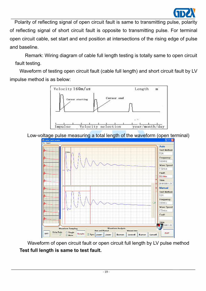
Polarity of reflecting signal of open circuit fault is same to transmitting pulse, polarity
of reflecting signal of short circuit fault is opposite to transmitting pulse. For terminal
open circuit cable, set start and end position at intersections of the rising edge of pulse
and baseline.
Remark: Wiring diagram of cable full length testing is totally same to open circuitfault testing.Waveform of testing open circuit fault (cable full length) and short circuit fault by LV
impulse method is as below:
Low-voltage pulse measuring a total length of the waveform (open terminal)
Waveform of open circuit fault or open circuit full length by LV pulse methodTest full length is same to test fault.

- 20 -
Waveform for impulse flash-over current samplingAnalysis in "manual waveform area":press"Zoom+/Zoom-"button,make the testedwaveform width is more suitable for fault distance interpretation.then use cursor
and "<<cursor/cursor>>" to select more suitable waveform inflection point.Moving cursor to read fault distance: this software is fully automatic, divided into
two areas, the upper area will automatically draw the waveform to choose the optimalone and automatically clip;Automatic display fault distance.If you think unassured, youcan do the following operation: double-click any point in the upper zone to select thewaveform to the lower zone, and there are "cursors" andcorresponding"<<cursor/cursor>>" button bottom right of the screen.press cursor tomove the cursor line to the inflection point of start waveform and echo waveform.Thenumber displayed between the two cursors is the distance from the fault point to thetest end.
Then press "save" to save or cancel .
3. Impulse flash-over current method
High resistance fault occupy 90% of total fault. Although most of them can betested by multiple pulse method, it can not resolve the problem of voltage drop and ultrahigh resistance fault discharge. We can use impulse HV flash-over current method orDC HV flash-over method to resolve these faults.
For impulse HV flash-over method, we usually use current sample method.Connect wires according to wire diagram, the select transmitting velocity. Fine-tuningamplitude to 1/3 position, then press “sample”button.

- 21 -
Adjust ball gap (operator box current is more than 10A-15A is regarded as notdischarge, you need to adjust ball gap and boost impulse voltage) and switch on powersupply to boost voltage of cable be tested. Fault point will discharge once the voltage toa certain value. You can adjust “input amplitude” to get more standard waveform.Impulse flash-over wave as below :If system crashed (terminal error), exit the testing system and press “reset”button tore-enter into system and re-sample.
Waveform characteristics: Transmitting pulse is positive then reflecting pulse isalso positive but there is negative reflecting pulse in front edge which is far smaller thanpositive pulse.This inflection point is the inflection point of fault point
When you set the position of cursor, blue cursor should be in intersection ofpositive pulse rising edge and baseline. Green cursor should be in intersection ofnegative reflecting pulse drop edge and baseline. You can use fine-tuning to movecursor to proper position. Test result area display the rough test distance.
If no negative pulse, then set terminal cursor in intersection of rising edge ofreflecting pulse and baseline, the fault distance display on screen will increase about15%. Deduct this 15% you will get accurate fault distance.
If need to enlarge waveform to see inflection point clearly in manual analysis area,choose single screen operation, analyze waveform , rough test with small error .
Notice: Please adjust ball gap according to cable voltage grade (1mm representsapproximately 3KV).

- 22 -
Wire connection for impulse HV flash-over method
4. HV flash-over test method waveform
(1) Waveform when fault near to testing terminal

- 23 -
(2) Waveform when fault in middle part of cable
(a)Near (b)Far
(3)Waveform when fault is near test end terminal
(a)short cable (b)long cable
(4)Diagram of waveform changing of HV flash-over method
(a)Very near (b)Near

- 24 -
Cable initial terminal Cable middle cable
Notice for HV flash-over method:
Because high operating voltage may cause heavily personnel injury or device
damage, you must pay special attentions to following items if you use multiple pulse
method or impulse HV flash-over method:
1) HV instruments should be operated by professional. Before you connect wires
or move device, make sure that power is off and completely discharged.
2) HV test instruments and cable fault locator should use separate power source
and connecting wires of cable fault locator should be far from HV wire. Computer
should cut off external power supply and remove mouse.
3) Make sure that HV ground terminal and operate box ground terminal connects
to cable sheath and earth.
4) If you use flash-over method, make sure that you made right setting in “work
mode” menu or it may damage LV pulse circuitry of test instruments.
5) Before testing, you should add HV to make sure that every connecting point
doesn’t discharge but fault point is already discharged, then start test.
6) There should be some protections if you test by HV near combustible materials.

- 25 -
Chapter V Accessories of
1.Current sampler
When you use HV flash-over method, connects red and black wiring terminal of
sampler to red and black clips of testing wiring and put current sampler parallel to
capacitor ground wire about 3-5cm far. The distance is depends on signal-intensity, the
standard is to get better waveform.
2.connecting cable
We provides you one connecting cables for flash-over test. Shown as below:
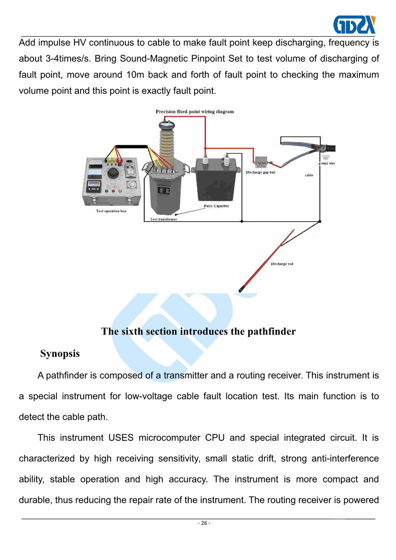
3.Wiring diagram of precisely locating
Precisely locating is key point of cable fault test. Remove HM-A100 host and
HM251 multiple pulse generator after rough test and connect wires as shown below.
- 26 -
Add impulse HV continuous to cable to make fault point keep discharging, frequency is
about 3-4times/s. Bring Sound-Magnetic Pinpoint Set to test volume of discharging of
fault point, move around 10m back and forth of fault point to checking the maximum
volume point and this point is exactly fault point.
The sixth section introduces the pathfinder
Synopsis
A pathfinder is composed of a transmitter and a routing receiver. This instrument is
a special instrument for low-voltage cable fault location test. Its main function is to
detect the cable path.
This instrument USES microcomputer CPU and special integrated circuit. It is
characterized by high receiving sensitivity, small static drift, strong anti-interference
ability, stable operation and high accuracy. The instrument is more compact and
durable, thus reducing the repair rate of the instrument. The routing receiver is powered

- 27 -
by large capacity battery and has the advantage of longer waiting time.
I. basic composition and main purpose
This instrument consists of the following two parts:
Transmitter: sends test signal to the tested low voltage cable.
Routing receiver: receiving signals by antennas near buried cables (low-voltage cables).
To facilitate the detection of buried cables paths and receiving antenna can be
horizontal, vertical, and depth of 45 ° Angle adjustment.
Cable path signal generator Cable Path Signal Received
Ii. Technical indicators
1. Detection distance < 15km
2. Detection depth 3m
3. Routing error < 5cm
4. Transmitter:
Output frequency: transmission frequency 9.82kHz
Output power: 2W
5. Routing receiver:
Input frequency: 9.82kHz
Detection routing error: 2cm

- 28 -
Detection depth error: 5cm
Electric pool: 9V battery, working for 8 hours continuously
Iii. Operation instructions
3.1 preparation before detection
1. Test the battery level
Routing receiver: after starting up, display the battery power. If less than
10%, replace the battery.
2. Suspended cable ends
Under normal circumstances, the end of the tested low-voltage cable is
disconnected from the ground, so it is only necessary to disconnect the cable
starting end from the distribution cabinet (the zero line grounding must be
unwound).
3.2 use method of transmitter
Note: when the transmitter is working, the peak output voltage can reach
300V (open circuit voltage). Do not touch the output end with your hands to avoid
electric shock. Do not connect the transmitter to live cable and do not short-circuit
the output directly.
1. Please close the transmitter before connecting it.
2. Insert the red and black output lines into the corresponding output jack of
the transmitter.
3. Red output wire clip, clip in the cable good phase. Then the cable is well
grounded.
If the cable is fully armored, the outer sheath is not broken. Can also open

- 29 -
the test end armoring, red clip clip on the armoring for testing.
4. Black output line clamp test end of the clamp system.
5. Connect the 12V power adapter, turn on the power switch of the
transmitter and display the work
Voltage, transmission frequency. The transmitter is working.
6. Short-circuit the output red-black clamp when the machine is turned on.
FIG. 1 transmitter connection diagram
3.3 function and usage of routing receiver
1) function of routing receiver
Detect the routing and burial depth of low-voltage cables. The detection
principle is peak value method and null value method.
Peak method (rough measurement method) : rotate the probe and probe
rod into a 90 degree Angle and parallel to the ground, and perpendicular to the
direction of low-voltage cable. At this point, the peak point is the point when the
signal is the strongest when it is directly above the low-voltage cable (the speaker
is the loudest). This detection method is called peak method (see figure 2). Move
the probe left and right along the low-voltage cable, and the signal is weakened
(the speaker sound is weakened), that is, the middle sound is loud, while the two

- 30 -
sides sound is small. The measured line at the peak point is the direction of the
low-voltage cable. For rough routing.
FIG. 2 peak method Figure 3. Valley method
Valley method (precision method) : if the probe is rotated to a 0 degree
Angle with the probe rod, the probe is perpendicular to the ground. When the
low-voltage cable is directly above, the signal received is the weakest (the speaker
sound is the smallest, this point is the null point), this detection method is called
null value method, or dumb point method (see figure 3). Move the probe left and
right along the low-voltage cable, and the signal will be stronger (the speaker will
be louder), that is, the middle sound will be smaller, and the two sides will be louder.
The connection of its null point (or dummy point) is the direction of the low-voltage
cable. For precise routing.
2) routing receiver usage
(1) open the routing receiver power switch, and adjust the "amplitude
adjustment" knob;

- 31 -
(2) at the beginning to find the measured low voltage cable;
The method is as follows: 3 meters away from the transmitter, use the peak
method mentioned above to detect every cable in the vicinity, and the low-voltage
cable to be tested is the one with the loudest sound.
Continue to find the cable route
At this time, the null method is used to detect the low-voltage cable routing,
because this method is more accurate in the absence of other interference
detection.
3) detect the buried depth of low-voltage cable
The method is as follows: firstly, the null value method is used to find out the
low-voltage cable routing, and this point is set as point A; Then rotate the probe
into a 45-degree Angle with the probe rod. The lower end of the probe is attached
to the ground and vertically aligned with the direction of the low-voltage cable.
Move it horizontally (left and right). When the first null value of the received signal
appears, i.e., when the sound is the minimum, record the point as B (C), and the
straight-line distance of AB (AC) point on the ground is the buried depth of the
low-voltage cable, AD. The general error is about 5CM. (see figure 4) this method
is also called triangulation:
Actual burial depth = AD+ correction coefficient 5CM
Note: the accuracy of detecting the buried depth of low-voltage cables will
be affected by soil conditions, adjacent cables and cable metal materials. When
detecting the buried depth, avoid the bend of the low-voltage cable, and leave the
transmitter 10 meters away, so as to avoid inaccurate depth determination or

- 32 -
increase the error.
Figure 4.
Routing detection
1. Influence of adjacent cables
When the signal strength measured on one side of the low-voltage cable is
much lower than that on the other side, it may be affected by other cables adjacent
to the low-voltage cable. At this time, the ground cable should be re-inserted so
that the ground wire does not cross any adjacent cables, and the ground cable and
the measured low voltage cable as far as possible. Using the peak method test, the
loudest speaker sound is measured under the low voltage cable.
2. Detect low-voltage cable bends
When testing the route of low-voltage cable with null value method, the route
should be close to the curve of low-voltage cable at a slow speed, so that the
specific position of the curve can be measured near the outside of the low-voltage
cable. However, if the detection is carried out at a relatively fast speed, it will
suddenly increase the sound of the loudspeaker at the corner and make people
misjudge.
Probe around
The null value method was used for detection. When the probe comes to the

- 33 -
surround of the low-voltage cable, if the probe swings to the opposite side of the
surround, the routing receiver will reflect the normal peak; A very strong peak
occurs when the oscillation is directly above the circle.
Detect in dense areas
Adjacent cables interfere with the normal reception of the routing receiver. At
this time, the signal strength of the tested low-voltage cable should be increased,
and the signal strength of adjacent cables should be reduced. The method is as
follows:
(1) change the transmitter to the other end of the tested low-voltage cable to
send signals;
(2) improve the grounding situation, mobile ground brazing location.
V. matters needing attention
This instrument is used for outdoor work. Keep it clean and dry. When not in
use, the instrument should be put into a packing box and stored in a low
temperature and dry place. Before each operation, the battery power of the routing
receiver should be tested. When the meter is not used for a long time, the battery in
the routing receiver should be taken out; Route receiver battery replacement
method:
1. Prepare a 9V (block) battery;
2. Open the box cover of the pathfinder receiver;
3. Replace the old battery with a new one;
4. Install the instrument cover.

- 34 -
Complete sets of instruments
1. Cable path signal generator
2. One cable path signal receiver
3. One handle
4. One path signal receiving antenna
5. One core aviation plug cable
6. Two red and black test clip wires
7. One DC12V 3A power adapter
8. One copy of the manual
Section 7 introduction of fixed point instrument
I. overall overview
Due to the extremely complex environment of power cable
laying, accurate positioning is always a crucial step in cable fault
testing. Even if there is an accurate coarse side distance, it is
difficult for us to locate it quickly and accurately due to the
influence of external environment. Cable fault sound accurate
point magnetic meter is a portable, ultra-quiet, visual impact discharge receive accurate point
instrument, is specially used with high pressure surge generator, it utilizes advanced intelligent
background noise and sound track of new technology, which can realize continuous
optimization, the perfect sound effects, sound recording impact discharge characteristics and
implementation of the field will pick up the signal.
When the front-end continuous shock discharge is applied, the sound of the shock
discharge at the fault point within the range of the thick side spreads on the ground above the

- 35 -
cable and is recorded by the ground probe sensor on the ground. The distance between the
detection point and the real fault point of the cable can be obtained by means of the noise
volume of impulse discharge.
Ii. Technical features
Ultra-quiet noise reduction processing, excellent discharge sound quality, background is
more quiet, choose listening headphones for fast and reliable point fault location.
Select ultra-quiet technology and BNR intelligent background noise reduction technology,
can adjust the impact discharge volume.
Mold design of special self-falling sensor, and equipped with soft pavement, hardened
pavement, lawn sensor joint.
The selection of reliable imported connectors, to ensure the purity of sound, user-friendly
design of a highly adjustable probe handle, very applicable.
Iii. Technical parameters
Sensor dynamic range: sound channel >104dB.
Impact discharge sound amplification factor >90dB, impact discharge volume limit
84dB(A).
LCD: high brightness color screen, 320 x 240 pixels suitable for outdoor.
Continuous working time on site: alkaline replaceable battery, convenient for site use
1. Standard configuration:
• one receiver host, model number, including shoulder strap
• a sensor (ground probe microphone).
• one height adjustable handle with a height range of 450-750 mm

- 36 -
• one earphone with sound quality
• one signal line connecting the receiver host to the sensor, 1.20m long
• one hard ground probe, 18mm long
• one grass probe, 75 mm long
• 6 alkaline batteries, model IEC R6
• a manual in Chinese
2.receiver host connection and control
The following figure shows the connection method and control keys of the receiver host:
LCD display, one-button adjustment button, receiver host startup (long press 10 seconds
and the red LED indicator flashes)/shutdown (long press 3 seconds), mute open/close, connect
socket, connect sensor, connect socket, open earphone and prepare sensor
Iv. Site installation and operation
1. Connect the sensor to a suitable probe or probe
The sensor can be connected to two different probes, the standard configuration includes
an 18mm long hard ground probe and a 75mm long grass probe. The above probes and probes
can be threaded to suit a variety of ground covering conditions.

- 37 -
2. Connect the sensor with the handle
The figure below shows how to connect the adjustable handle to the sensor:
3. Adjust the height of the handle
The figure below shows the method to adjust the height of the handle:

- 38 -
4. Connect the sensor and headset with the receiver host
Connect the headset to the black socket of the receiver host. Note the white marking on
the aligning plug and socket. The plug is plug and play, do not rotate!
5, receiver host
5.1 opening of receiver host
The host can be turned on or off after pressing the power on and off button of the
receiver host. After a dozen seconds, the receiver host is ready for use, and the measurement
interface will be displayed.
5.2 self-test of battery power
When you boot up, please first look at the upper right corner of the display, check the
alkaline battery remaining power. If you find that the percentage of battery power is close to
25%, please charge it first, and use it after the power is more than 50%.
5.3 one-button fit knob
The host of the receiver is mainly adjusted by one-key fit single-key. Please refer to the
figure below for the use of one-button adjustment button:

- 39 -
gestures Measure the function of the
interface
Adjust the volume (sound
amplification)
5.4 display of measurement interface
Provide the sound signal in the headset, and display the relevant information that may be
useful when you are close to the fault point during the precise fixing process through the
measurement interface.
5. Starting to use cable fault precise locating instrument
Please connect the high-voltage integrated shock generator (high-voltage unit) to the
fault cable and start to apply the appropriate shock voltage, so that flashover breakdown
discharge occurs at the fault point of the fault cable. Appropriate impulse voltage refers to the
type of cable that is suitable for the test, and the maximum allowable impulse voltage will not
cause damage to the cable under test. For more details about using high voltage shock
generator (high voltage unit), please read the operation manual of integrated high voltage
power supply of this product.

- 40 -
1.1 precise fixed-point operation procedures
When you are close to the failure point, please follow the following procedures:
steps action
1 Place your ground-penetrating microphone in the starting position.
If no sound signal can be picked up at the measuring point. Please follow the cable
path under test. When you find that you have received the first useful shock
discharge sound signal, the LCD on the left side of the host will automatically display
the sound size of the measurement point.
If you are in a longer area and cannot pick up the shock discharge sound signal
through the ground probe microphone or headset, you should try to pinpoint the
exact point from the starting point in the opposite direction.
2
Please continue along the path of the cable under test, moving the distance one step
at a time, and adjust the position of the central axis of the cable under test at any
time if necessary. At each measuring point, please remain several impulse
discharge signals.
As you approach the cable failure point, you will hear a more intense knocking
sound, and the sound size of the current measurement point displayed will increase
sharply.
3Please send out to the microphone rotate 180 °, again with a smaller interval
near the point of failure.
4
Please continue to narrow the step distance to find the fault with the loudest
sound and determine the location of the fault point as accurately as possible. Then
make a precise mark on the ground.
1.2 shutdown:
Please press the power on/off button of the host machine for a long time.

- 41 -
Important note: when this set of equipment is used to test cable high-resistance fault,
flashover method shall be adopted. The fault point shall discharge with open fire. Please note
that it is strictly prohibited to test in high-gas and high-concentration flammable gas
environment. In this case, please contact the manufacturer and take other measures to test. In
the event of safety accidents and equipment manufacturers have nothing to do!
Sincerely thank you for using our company's cable fault test equipment. Due to our
continuous upgrading and improvement of the instrument, the physical appearance of the
instrument you see may be slightly different from the instruction, but its operating principle
and operation method are basically the same. Special need to give you that this tester is
integrated design, program curing, high reliability. Therefore, under the condition that it is not
connected with the high-pressure equipment, you can feel free to learn the operation
repeatedly according to the instructions and master its functions without worrying about the
damage to the instrument. When you have any problems in the operation or crash, you can
reset or shutdown to restart. I believe that as long as you learn diligently, you will soon master
the instrument operation and fault testing methods.
With cable tester, I believe it will bring great convenience to your work, and can solve
more than 98% of your work in the fault. If you encounter any difficulties and problems in use,
please contact our company in time. We will wholeheartedly provide you with the best
service.
Note:
Welcome to choose our instruments and equipment. This machine is a highly integrated
precision instrument with the same function as a laptop. Please do not use it on the Internet
when there is no test cable fault. Special person is recommended to keep it and use it. If it is

- 42 -
not used for half a year, please charge it once and do not open the main case at will.
Important note:
When testing the cable high-resistance fault with this set of equipment, flashover method
shall be adopted, and the fault point shall discharge and have the phenomenon of open fire.
When testing, please note that it is strictly prohibited to test in the environment of high gas
and high concentration flammable gas. In this case, please contact the manufacturer and take
other measures to test. In the event of safety accidents and equipment manufacturers have
nothing to do!