zyxel es-2108 series
TRANSCRIPT
ZyXEL ES-2108 Series (ES-2108/ES-2108G/ES-2108PWR/ES-2108-LC)
Ethernet Switch
Support Notes Version 3.60
Feb 2006
ES-2108 Series Switch Support Notes
All contents copyright (c) 2006 ZyXEL Communications Corporation. 2
INDEX How to manage & maintain your Switch?
Firmware Upgrade Restore a Configuration File Backing Up a Configuration File Load Factory Defaults
Physical Switch connection Connecting two switches via Fiber Channel (2108-LC) Separating a physical network into many virtual networks
Introduction to Virtual LAN Port Based Virtual LAN Setting up Port Based VLAN IEEE 802.1Q Tag-based VLAN Setting up Tag-based VLAN
To ring a network by building reducdent links and connections between Switch Introduction to Spanning Tree Protocol How does Spanning Tree Protocol Work?
Switching security MAC freeze
Centralized Management Introduction of SNMPc and NetAtlas *NetAtlas v1.02 supports ES-2108 & ES-2108G Cluster Management -- iStacking
FAQ What is ES-2108-LC
What is the default setting of the IP parameters? What is the default login Name and Password of the Web Configuration? How to access the Switch through the console port? What is default login password of the console, telnet, and FTP? How to change the password? How to access the Command Line Interface? If I forgot the Switch password, how can I reset the password to default? How do I configure an IP address? Is Online Help available on the Web GUI? How to restart device from Web? How to check the current running firmware version? Is the mini GBIC transceiver hot-swappable? What fiber cable can I use for the 100FX port? How far does the 100FX port support in Kilometer on ES-2108-LC? Do I need any addition stuff (such like transceiver) when I connect 2
ES-2108 Series Switch Support Notes
All contents copyright (c) 2006 ZyXEL Communications Corporation. 3
100FX Ports? Is Port 8 on EC-2108-LC the "Dual-Personality interface" which will share the interface with the Mini-GB (SFP) or 100FX Port? When I enabled Port Isolated mode, what is the uplink port on ES-2108-LC?
Remaining: The following demonstration may not use the exact model that you are using. However, their functions and settings work the same way.
ES-2108 Series Switch Support Notes
All contents copyright (c) 2006 ZyXEL Communications Corporation. 4
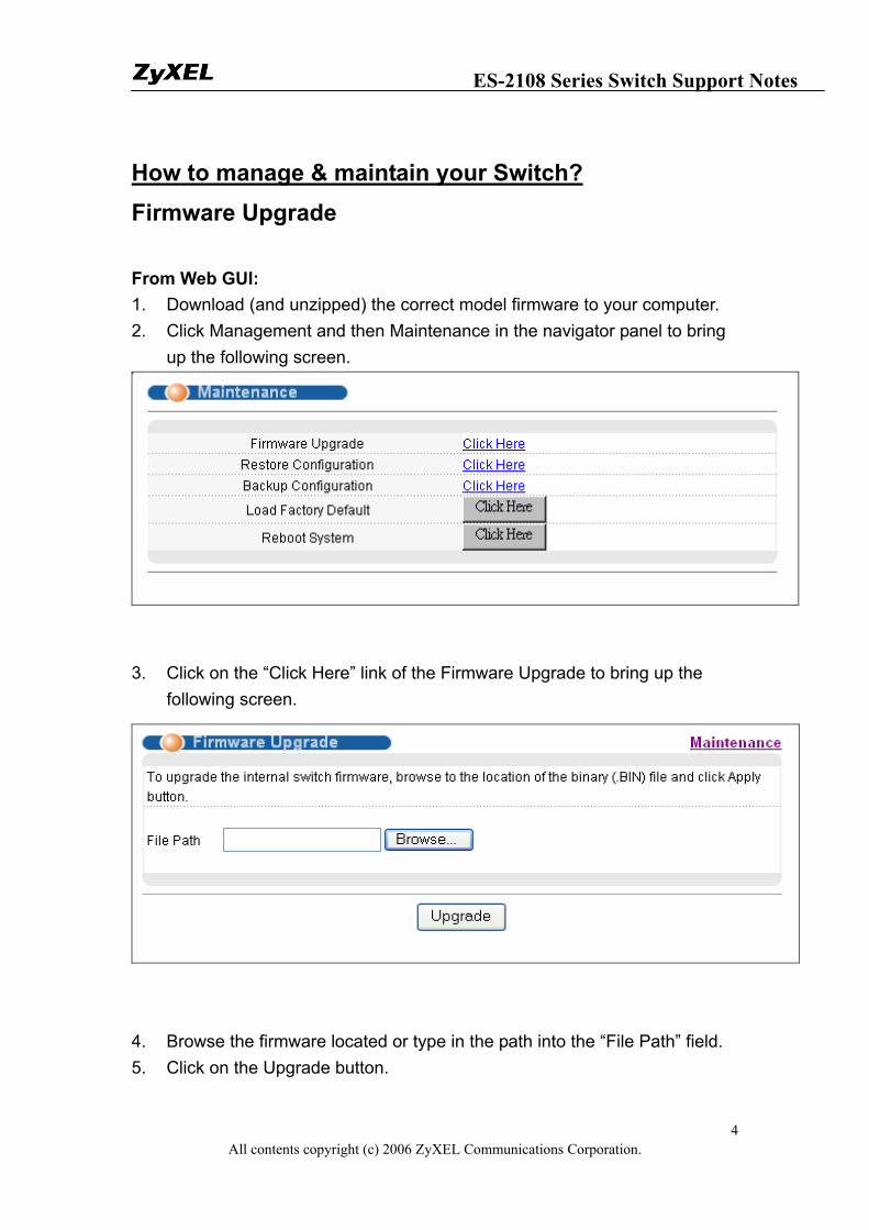
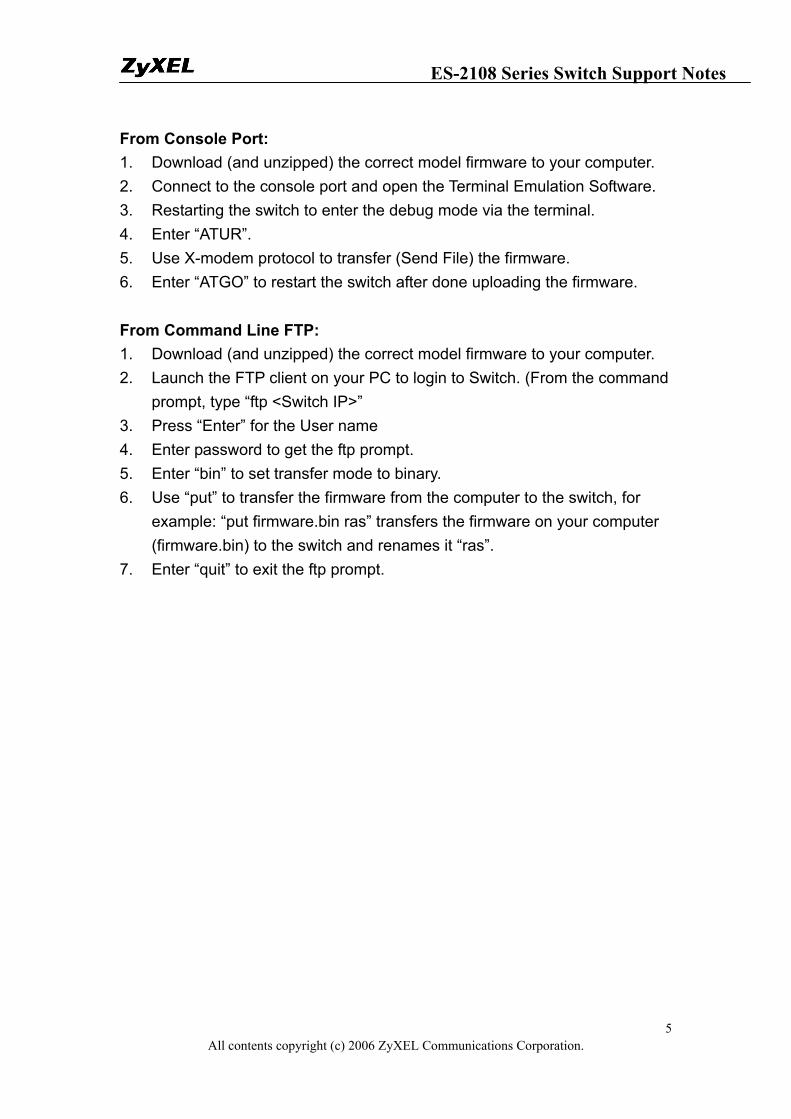
How to manage & maintain your Switch? Firmware Upgrade From Web GUI: 1. Download (and unzipped) the correct model firmware to your computer. 2. Click Management and then Maintenance in the navigator panel to bring
up the following screen.
3. Click on the “Click Here” link of the Firmware Upgrade to bring up the
following screen.
4. Browse the firmware located or type in the path into the “File Path” field. 5. Click on the Upgrade button.
ES-2108 Series Switch Support Notes
All contents copyright (c) 2006 ZyXEL Communications Corporation. 5
From Console Port: 1. Download (and unzipped) the correct model firmware to your computer. 2. Connect to the console port and open the Terminal Emulation Software. 3. Restarting the switch to enter the debug mode via the terminal. 4. Enter “ATUR”. 5. Use X-modem protocol to transfer (Send File) the firmware. 6. Enter “ATGO” to restart the switch after done uploading the firmware. From Command Line FTP: 1. Download (and unzipped) the correct model firmware to your computer. 2. Launch the FTP client on your PC to login to Switch. (From the command
prompt, type “ftp <Switch IP>” 3. Press “Enter” for the User name 4. Enter password to get the ftp prompt. 5. Enter “bin” to set transfer mode to binary. 6. Use “put” to transfer the firmware from the computer to the switch, for
example: “put firmware.bin ras” transfers the firmware on your computer (firmware.bin) to the switch and renames it “ras”.
7. Enter “quit” to exit the ftp prompt.
ES-2108 Series Switch Support Notes
All contents copyright (c) 2006 ZyXEL Communications Corporation. 6
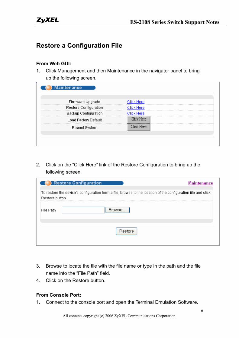
Restore a Configuration File From Web GUI: 1. Click Management and then Maintenance in the navigator panel to bring
up the following screen.
2. Click on the “Click Here” link of the Restore Configuration to bring up the
following screen.
3. Browse to locate the file with the file name or type in the path and the file
name into the “File Path” field. 4. Click on the Restore button. From Console Port: 1. Connect to the console port and open the Terminal Emulation Software.
ES-2108 Series Switch Support Notes
All contents copyright (c) 2006 ZyXEL Communications Corporation. 7
2. Restarting the Switch to enter the debug mode via the terminal. 3. Enter “ATLC” 4. Use X-modem protocol to transfer (Send File) the firmware. 5. Enter “ATGO” to restart the Switch after done uploading the configuration
file. From Command Line FTP: 1. Download (and unzipped) the correct model firmware to your computer. 2. Launch the FTP client on your PC to login to Switch. (From the command
prompt, type “ftp <Switch IP>”. 3. Press “Enter” for the User name 4. Enter password to get the ftp prompt. 5. Enter “bin” to set transfer mode to binary. 6. Use “put” to transfer the the configuration file from the computer to the
switch, for example: “put comfig.rom rom-0” transfers the firmware on your computer (config.rom) to the switch and renames it “rom-0”.
7. Enter “quit” to exit the ftp prompt.
ES-2108 Series Switch Support Notes
All contents copyright (c) 2006 ZyXEL Communications Corporation. 8
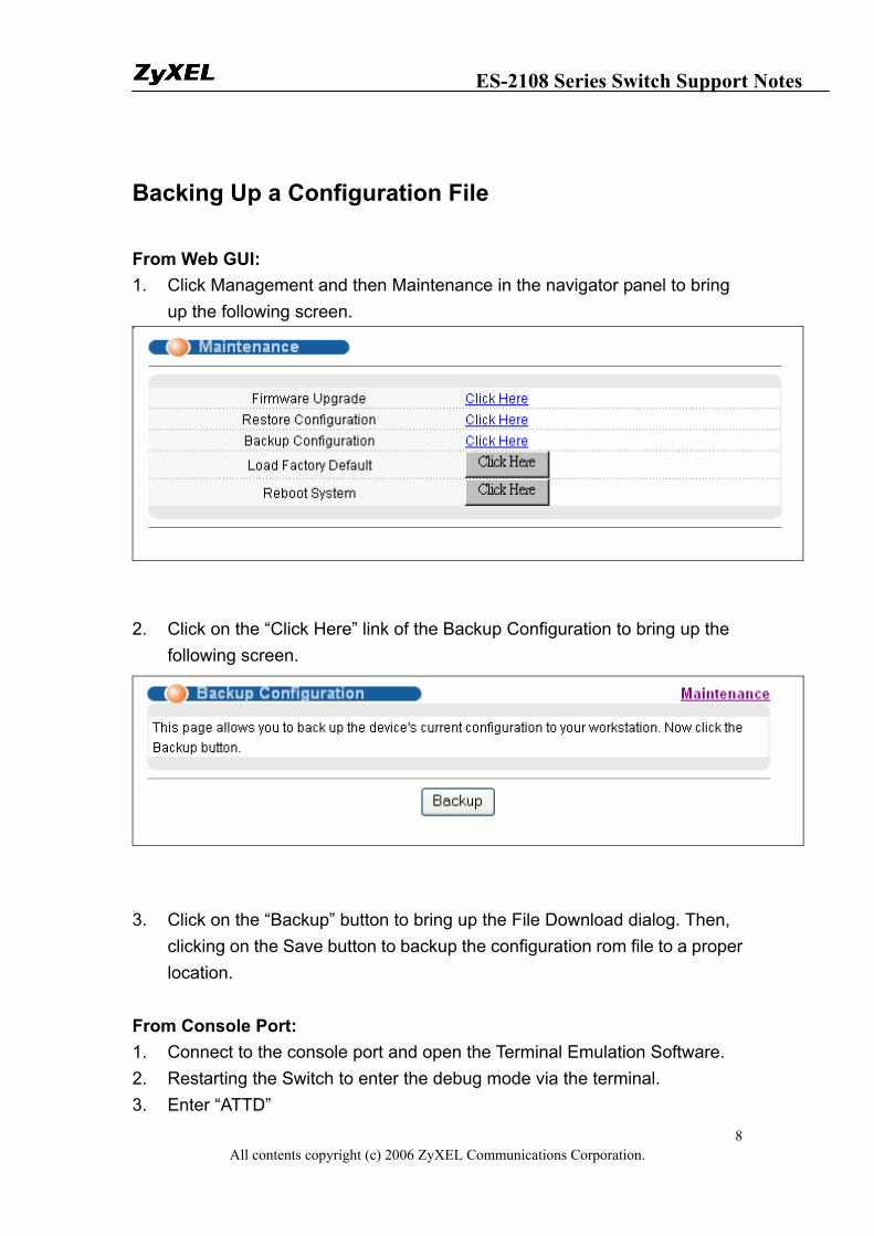
Backing Up a Configuration File From Web GUI: 1. Click Management and then Maintenance in the navigator panel to bring
up the following screen.
2. Click on the “Click Here” link of the Backup Configuration to bring up the
following screen.
3. Click on the “Backup” button to bring up the File Download dialog. Then,
clicking on the Save button to backup the configuration rom file to a proper location.
From Console Port: 1. Connect to the console port and open the Terminal Emulation Software. 2. Restarting the Switch to enter the debug mode via the terminal. 3. Enter “ATTD”
ES-2108 Series Switch Support Notes
All contents copyright (c) 2006 ZyXEL Communications Corporation. 9
4. Use X-modem protocol to transfer (Receive File) the firmware. 5. Enter “ATGO” to restart the Switch after done uploading the configuration
file. From Command Line FTP: 1. Download (and unzipped) the correct model firmware to your computer. 2. Launch the FTP client on your PC to login Switch. (From the command
prompt, type “ftp <Switch IP>” 3. Press “Enter” for the User name 4. Enter password to get the ftp prompt. 5. Enter “bin” to set transfer mode to binary. 6. Use “get” to transfer the firmware from the computer to the switch, for
example: “get rom-0 config.rom” transfers the firmware on your computer (config.rom) to the switch and renames it “config.rom”.
7. Enter “quit” to exit the ftp prompt.
ES-2108 Series Switch Support Notes
All contents copyright (c) 2006 ZyXEL Communications Corporation. 10
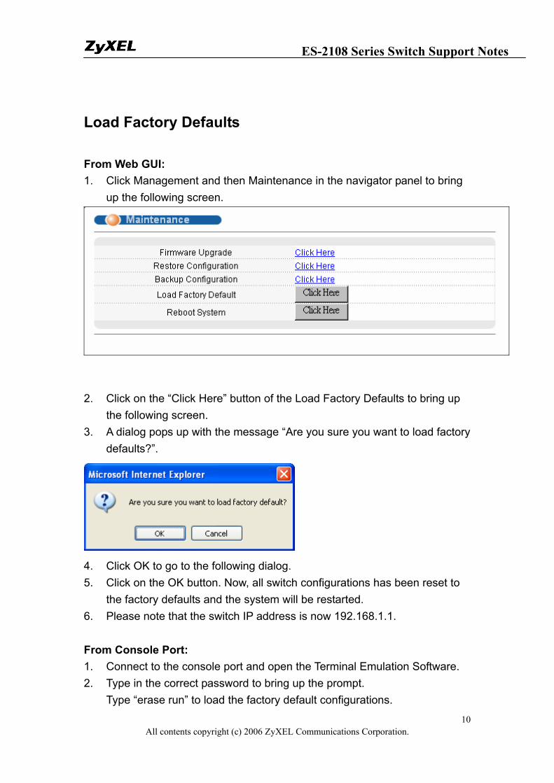
Load Factory Defaults From Web GUI: 1. Click Management and then Maintenance in the navigator panel to bring
up the following screen.
2. Click on the “Click Here” button of the Load Factory Defaults to bring up
the following screen. 3. A dialog pops up with the message “Are you sure you want to load factory
defaults?”.
4. Click OK to go to the following dialog. 5. Click on the OK button. Now, all switch configurations has been reset to
the factory defaults and the system will be restarted. 6. Please note that the switch IP address is now 192.168.1.1. From Console Port: 1. Connect to the console port and open the Terminal Emulation Software. 2. Type in the correct password to bring up the prompt.
Type “erase run” to load the factory default configurations.
ES-2108 Series Switch Support Notes
All contents copyright (c) 2006 ZyXEL Communications Corporation. 11
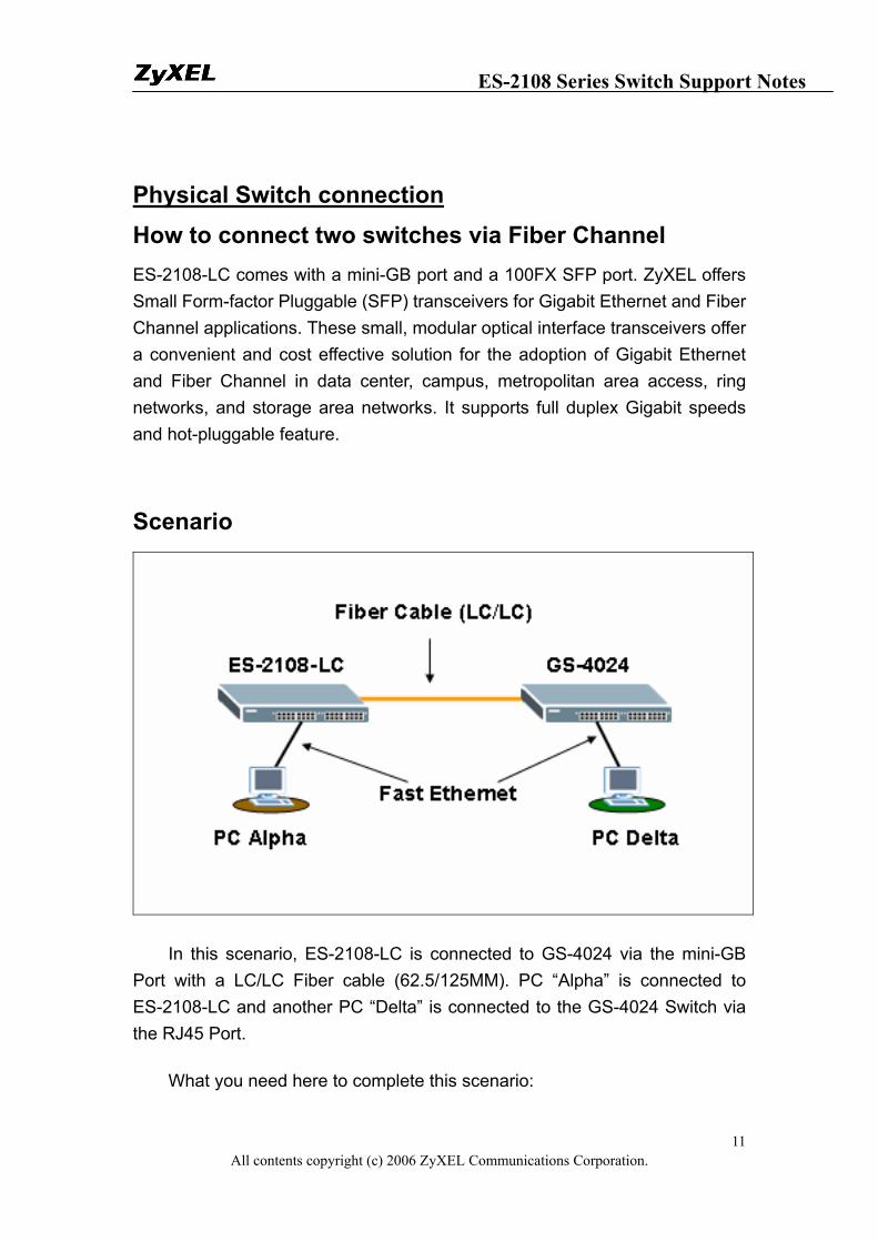
Physical Switch connection How to connect two switches via Fiber Channel ES-2108-LC comes with a mini-GB port and a 100FX SFP port. ZyXEL offers Small Form-factor Pluggable (SFP) transceivers for Gigabit Ethernet and Fiber Channel applications. These small, modular optical interface transceivers offer a convenient and cost effective solution for the adoption of Gigabit Ethernet and Fiber Channel in data center, campus, metropolitan area access, ring networks, and storage area networks. It supports full duplex Gigabit speeds and hot-pluggable feature.
Scenario
In this scenario, ES-2108-LC is connected to GS-4024 via the mini-GB Port with a LC/LC Fiber cable (62.5/125MM). PC “Alpha” is connected to ES-2108-LC and another PC “Delta” is connected to the GS-4024 Switch via the RJ45 Port.
What you need here to complete this scenario:
ES-2108 Series Switch Support Notes
All contents copyright (c) 2006 ZyXEL Communications Corporation. 12
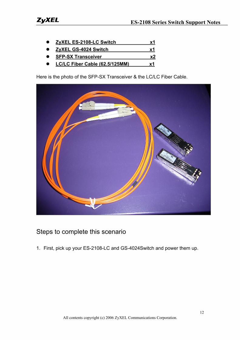
ZyXEL ES-2108-LC Switch x1 ZyXEL GS-4024 Switch x1 SFP-SX Transceiver x2 LC/LC Fiber Cable (62.5/125MM) x1
Here is the photo of the SFP-SX Transceiver & the LC/LC Fiber Cable.
Steps to complete this scenario
1. First, pick up your ES-2108-LC and GS-4024Switch and power them up.
ES-2108 Series Switch Support Notes
All contents copyright (c) 2006 ZyXEL Communications Corporation. 13
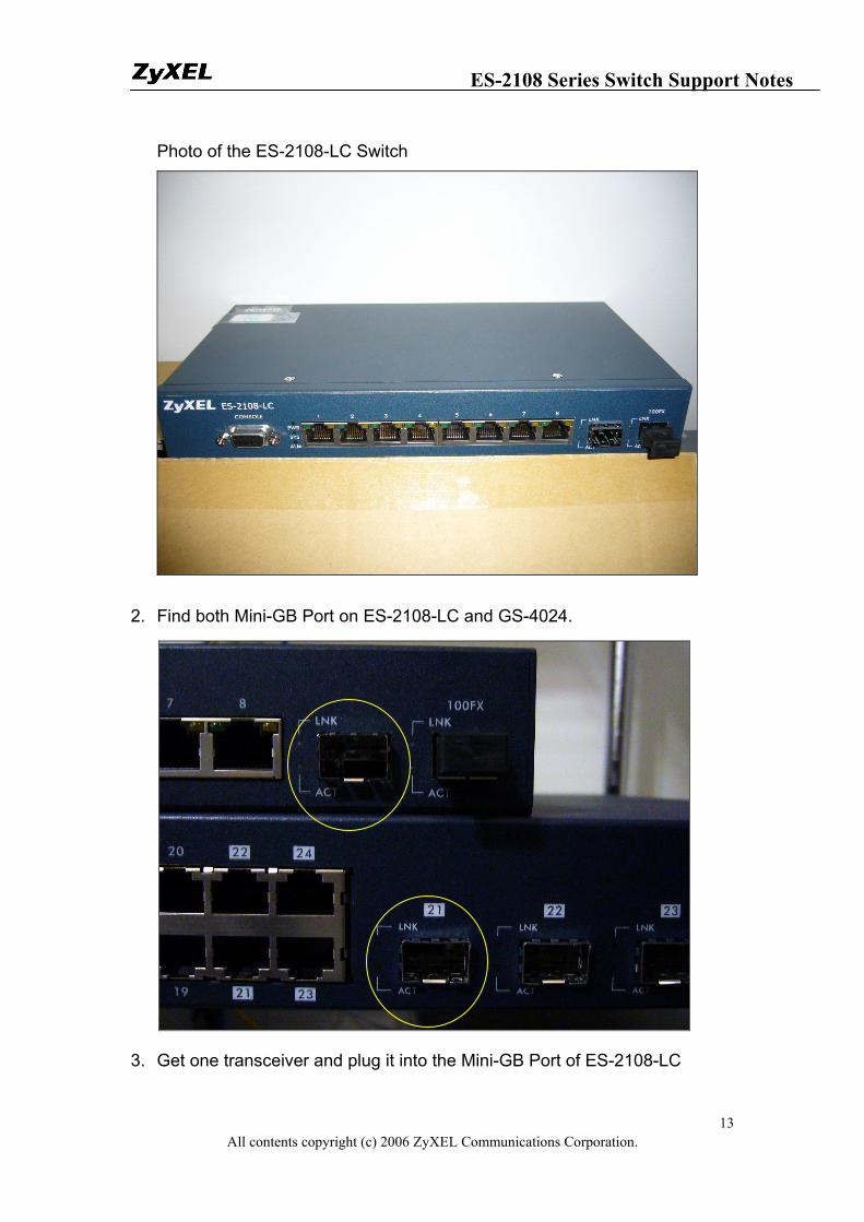
Photo of the ES-2108-LC Switch
2. Find both Mini-GB Port on ES-2108-LC and GS-4024.
3. Get one transceiver and plug it into the Mini-GB Port of ES-2108-LC
ES-2108 Series Switch Support Notes
All contents copyright (c) 2006 ZyXEL Communications Corporation. 14
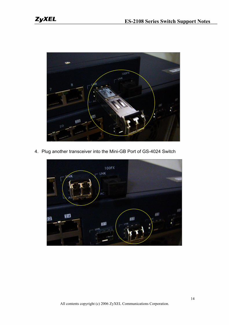
4. Plug another transceiver into the Mini-GB Port of GS-4024 Switch
ES-2108 Series Switch Support Notes
All contents copyright (c) 2006 ZyXEL Communications Corporation. 15
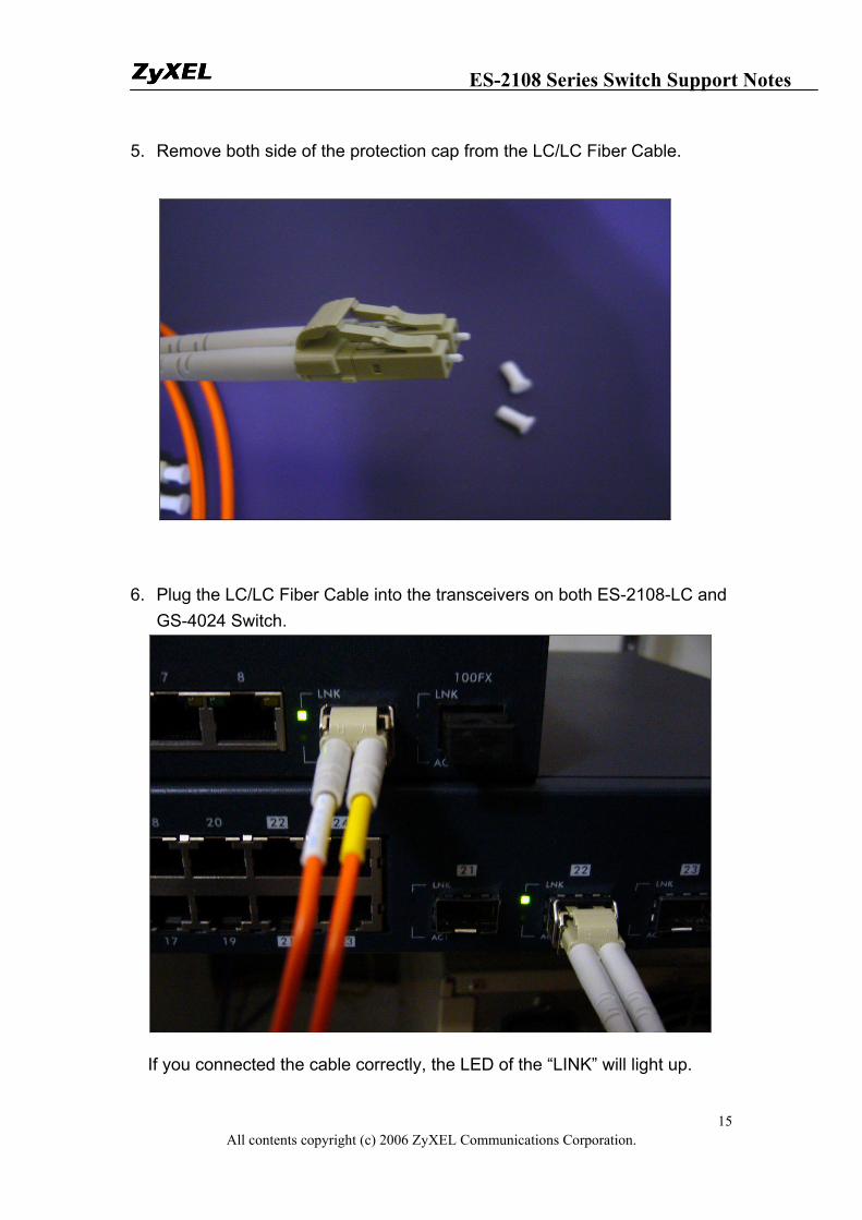
5. Remove both side of the protection cap from the LC/LC Fiber Cable.
6. Plug the LC/LC Fiber Cable into the transceivers on both ES-2108-LC and GS-4024 Switch.
If you connected the cable correctly, the LED of the “LINK” will light up.
ES-2108 Series Switch Support Notes
All contents copyright (c) 2006 ZyXEL Communications Corporation. 16
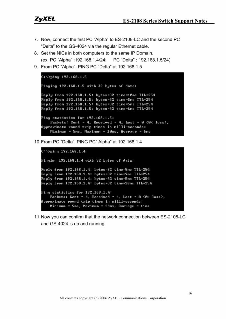
7. Now, connect the first PC “Alpha” to ES-2108-LC and the second PC “Delta” to the GS-4024 via the regular Ethernet cable.
8. Set the NICs in both computers to the same IP Domain. (ex, PC “Alpha” :192.168.1.4/24; PC “Delta” : 192.168.1.5/24)
9. From PC “Alpha”, PING PC “Delta” at 192.168.1.5
10. From PC “Delta”, PING PC” Alpha” at 192.168.1.4
11. Now you can confirm that the network connection between ES-2108-LC
and GS-4024 is up and running.
ES-2108 Series Switch Support Notes
All contents copyright (c) 2006 ZyXEL Communications Corporation. 17
Separating a physical network into many virtual networks
What is Virtual LAN?
• VLAN Overview
A VLAN (Virtual Local Area Network) allows a physical network to be partitioned into multiple logical networks. Stations on a logical network belong to one group called VLAN Group. A station can belong to more than one group. The stations on the same VLAN group can communicate with each other. With VLAN, a station cannot directly talk to or hear from stations that are not in the same VLAN group(s); the traffic must first go through a router.
In MTU or IP-DSLAM applications, VLAN is vital in providing isolation and security among the subscribers. When properly configured, VLAN prevents one subscriber from accessing the network resources of another on the same LAN, thus a user will not see the printers and hard disks of another user in the same building.
VLAN also increases network performance by limiting broadcasts to a smaller and more manageable logical broadcast domain. A VLAN group is a broadcast domain. In traditional Layer-2 switched environments, all broadcast packets go to each and every individual port. With VLAN, all broadcasts are confined to a specific broadcast domain.
There are two most popular VLAN implementations, Port-based VLAN and IEEE 802.1q Tagged VLAN. ES-2108-LC supports both VLAN implementations. The most difference between both VLAN implementations is Tagged VLAN can across Layer-2 switch but Port-based VLAN cannot.
• Port-based VLAN
Port-based VLANs are VLANs where the packet forwarding decision is based
ES-2108 Series Switch Support Notes
All contents copyright (c) 2006 ZyXEL Communications Corporation. 18
on the destination MAC address and its associated port. You must define outgoing ports allowed for each port when using port-based VLANs. Note that VLAN only governs the outgoing traffic, in the other word, it is unidirectional. Therefore, if you wish to allow two subscriber ports to talk to each other, e.g., between conference rooms in a hotel, you must define the egress (outgoing port) for both ports. An egress port is an outgoing port, that is, a port through which a data packet leaves.
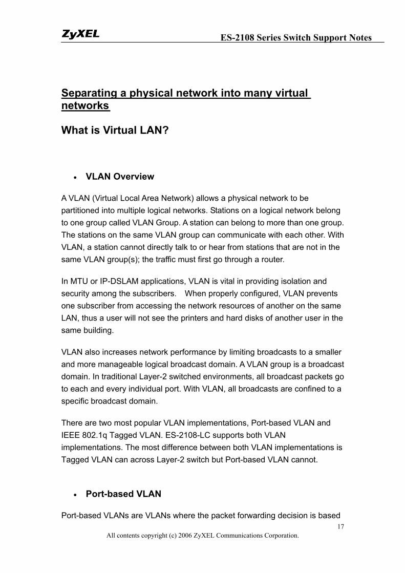
There are 5 hosts (Host A, B, C, D and E) connected to a 5-port layer-2 switch which supported port-based VLAN.
Case 1: Host A and Host B can talk to each other, because they are in the same VLAN group. But Host A and Host B can't talk to Host C, D, and E.
Port-based VLAN definition:
• Egress port for port 1: port 2 • Egress port for port 2: port 1
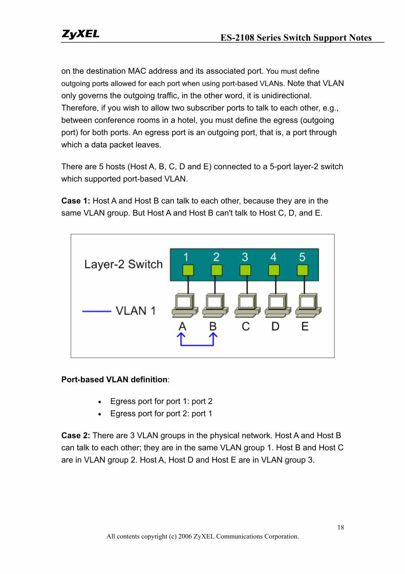
Case 2: There are 3 VLAN groups in the physical network. Host A and Host B can talk to each other; they are in the same VLAN group 1. Host B and Host C are in VLAN group 2. Host A, Host D and Host E are in VLAN group 3.
ES-2108 Series Switch Support Notes
All contents copyright (c) 2006 ZyXEL Communications Corporation. 19
Port-based VLAN definition:
• Egress port for port 1: port 2, port 4, port 5 • Egress port for port 2: port 1, port 3 • Egress port for port 3: port 2 • Egress port for port 4: port 1, port 5 • Egress port for port 5: port 1, port 4
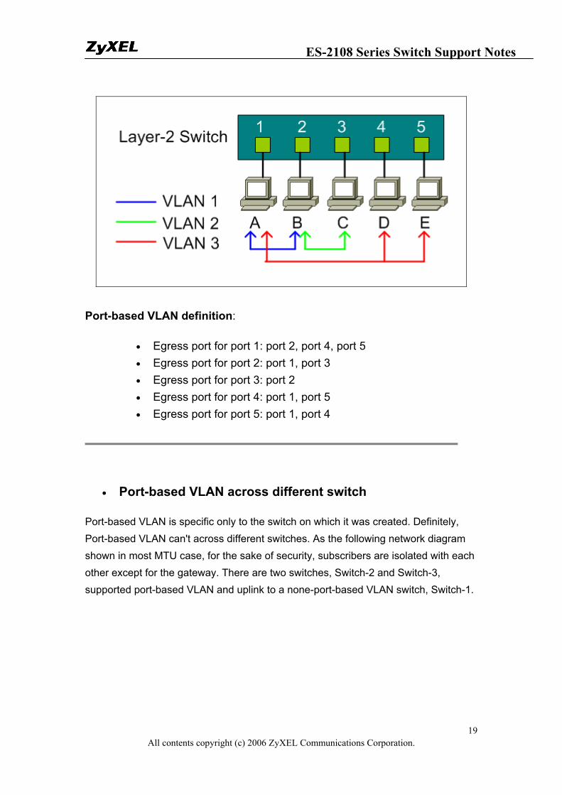
• Port-based VLAN across different switch
Port-based VLAN is specific only to the switch on which it was created. Definitely, Port-based VLAN can't across different switches. As the following network diagram shown in most MTU case, for the sake of security, subscribers are isolated with each other except for the gateway. There are two switches, Switch-2 and Switch-3, supported port-based VLAN and uplink to a none-port-based VLAN switch, Switch-1.
ES-2108 Series Switch Support Notes
All contents copyright (c) 2006 ZyXEL Communications Corporation. 20
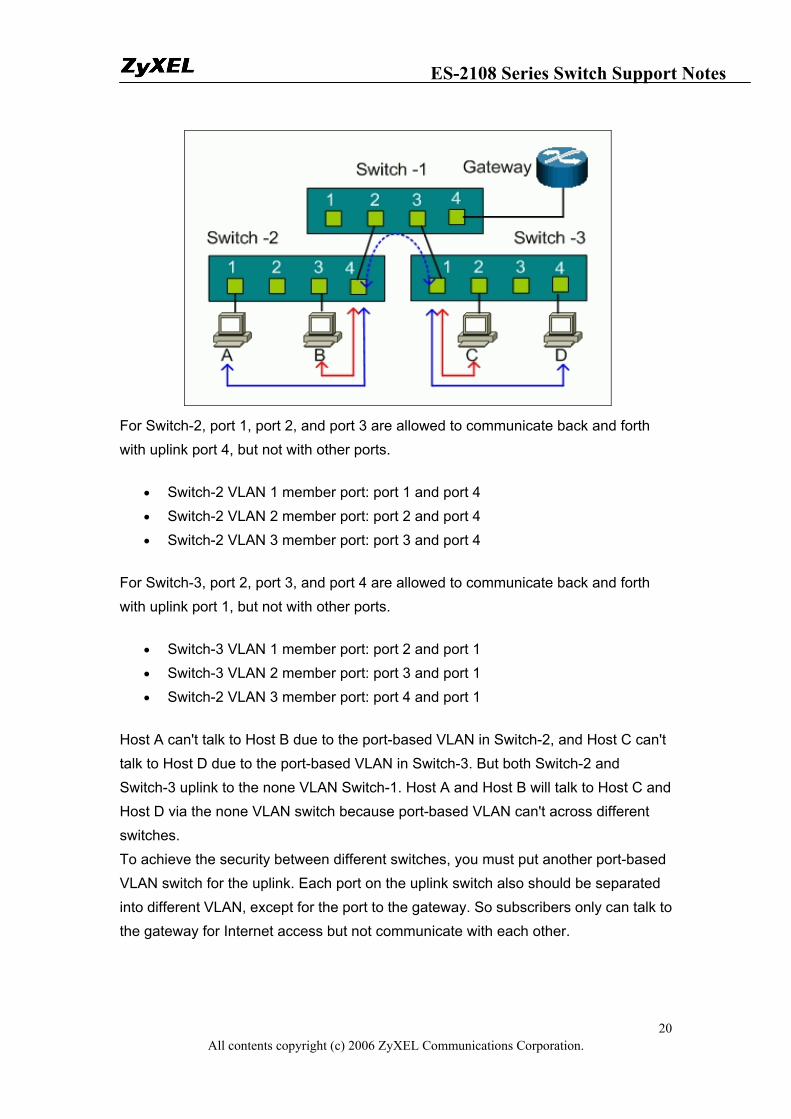
For Switch-2, port 1, port 2, and port 3 are allowed to communicate back and forth with uplink port 4, but not with other ports.
• Switch-2 VLAN 1 member port: port 1 and port 4 • Switch-2 VLAN 2 member port: port 2 and port 4 • Switch-2 VLAN 3 member port: port 3 and port 4
For Switch-3, port 2, port 3, and port 4 are allowed to communicate back and forth with uplink port 1, but not with other ports.
• Switch-3 VLAN 1 member port: port 2 and port 1 • Switch-3 VLAN 2 member port: port 3 and port 1 • Switch-2 VLAN 3 member port: port 4 and port 1
Host A can't talk to Host B due to the port-based VLAN in Switch-2, and Host C can't talk to Host D due to the port-based VLAN in Switch-3. But both Switch-2 and Switch-3 uplink to the none VLAN Switch-1. Host A and Host B will talk to Host C and Host D via the none VLAN switch because port-based VLAN can't across different switches. To achieve the security between different switches, you must put another port-based VLAN switch for the uplink. Each port on the uplink switch also should be separated into different VLAN, except for the port to the gateway. So subscribers only can talk to the gateway for Internet access but not communicate with each other.
ES-2108 Series Switch Support Notes
All contents copyright (c) 2006 ZyXEL Communications Corporation. 21
For Switch-1, port 1, port2, and port 3 are allowed to communicate back and forth with uplink port 4, but not with other ports.
• Switch-1 VLAN 1 member port: port 1 and port 4 • Switch-1 VLAN 2 member port: port 2 and port 4 • Switch-1 VLAN 3 member port: port 3 and port 4
How to configure Port-Based VLAN
Port-based VLANs are VLANs where the packet forwarding decision is based on the destination MAC address and its associated port.
ES-2108 Series Switch Support Notes
All contents copyright (c) 2006 ZyXEL Communications Corporation. 22
Scenario
In this scenario, Port Based VLAN is used to separate one physical Switch into two smaller logical Switches. Port 1~4 and 9, 10 are in one group. And Port 5~10 are in another group. Port-based VLANs are specific only to the switch on which they were created.
ES-2108 Series Switch Support Notes
All contents copyright (c) 2006 ZyXEL Communications Corporation. 23
Configuring your Switch to fulfill this scenario (GUI)
1. Connect port 1 with a PC or Notebook via the RJ45 Cable. 2. By default the MGMT IP on every port is 192.168.1.1/24 3. Set your NIC to 192.168.1.2/24 4. Open an Internet browser such as IE and give http://192.168.1.1 on
the URL. 5. By default you will need to put “admin” as the username and “1234” as
the password. 6. After you login successfully, you will see a similar screen like below.
7. First, we need to tell the Switch to run VLAN as port based instead of 802.1q based. In order to do so, we first click on the “Basic Setting”, then “Switch Setup”; on your right screen the VLAN Type, choose “Port Based” instead of “802.1Q”, and click “Apply” to save your changes.
ES-2108 Series Switch Support Notes
All contents copyright (c) 2006 ZyXEL Communications Corporation. 24
8. Now, you need to tell the Switch how you are going to separate the physical Switch into some logical small Switches. Thus, we click “Advanced Application” then “VLAN”. On the right screen, check the boxes to suit your need. In this case, we need to make port 1~4 and port 9, 10 in a group in order for them to communicate in both ways. And port 5~10 in another group but these two groups cannot talk with each others. Here we also logically defined Port 9 and Port 10 as the uplink ports. Therefore, both groups can pass data to Port 9 and Port 10. In another word, these two ports belong to both of the groups on the same time. Please confirm if your setting looks similar to below.
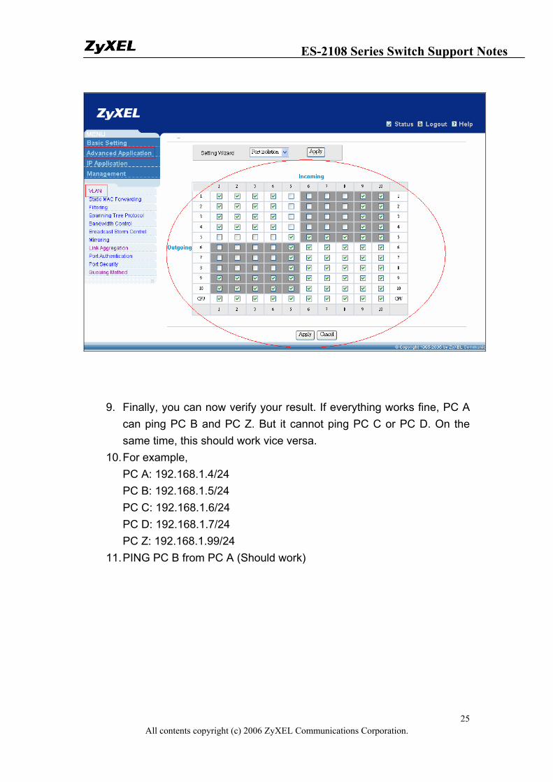
ES-2108 Series Switch Support Notes
All contents copyright (c) 2006 ZyXEL Communications Corporation. 25
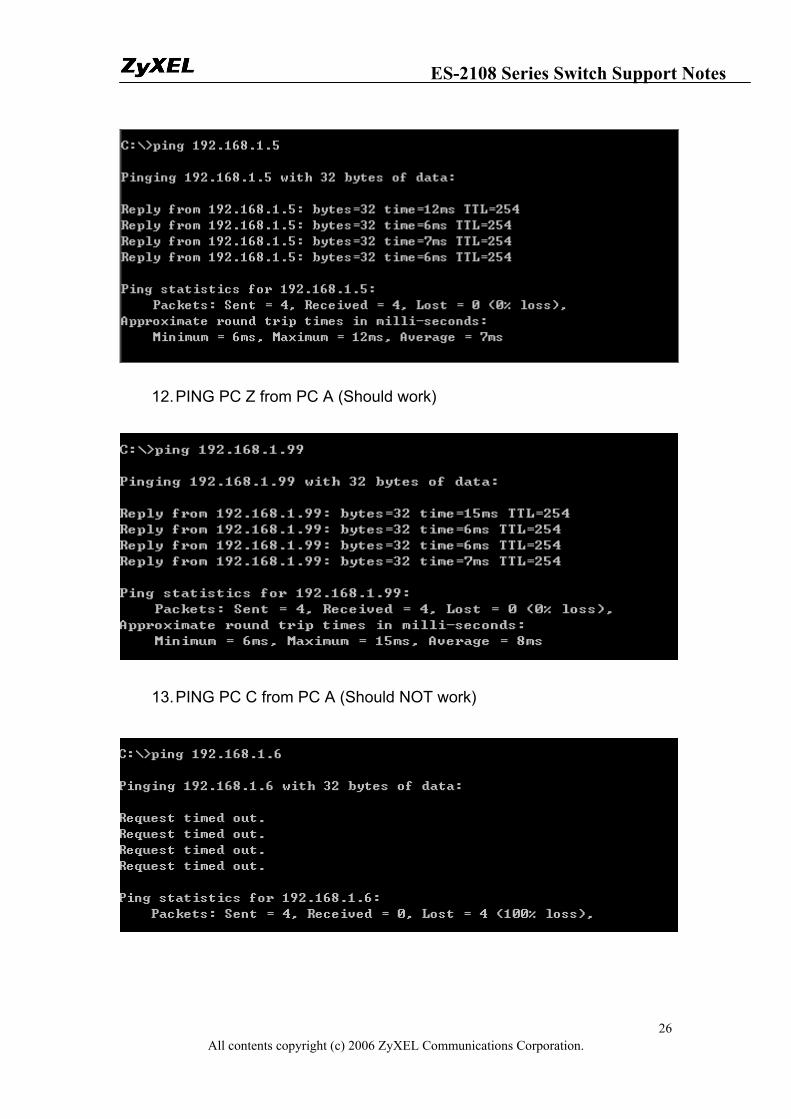
9. Finally, you can now verify your result. If everything works fine, PC A can ping PC B and PC Z. But it cannot ping PC C or PC D. On the same time, this should work vice versa.
10. For example, PC A: 192.168.1.4/24 PC B: 192.168.1.5/24 PC C: 192.168.1.6/24 PC D: 192.168.1.7/24 PC Z: 192.168.1.99/24
11. PING PC B from PC A (Should work)
ES-2108 Series Switch Support Notes
All contents copyright (c) 2006 ZyXEL Communications Corporation. 26
12. PING PC Z from PC A (Should work)
13. PING PC C from PC A (Should NOT work)
ES-2108 Series Switch Support Notes
All contents copyright (c) 2006 ZyXEL Communications Corporation. 27
Configuring your Switch to fulfill this scenario (CLI)
1. Connect the Switch Console port with your PC or Notebook. 2. Open your Terminal program.(Ex, Hyper Terminal in Windows
System) 3. Make sure that your port settings are
bps:9600 Data bits:8 Parity: None Stop bits:1 Flow control: None:
4. After you connected successfully, give the correct user name and password.
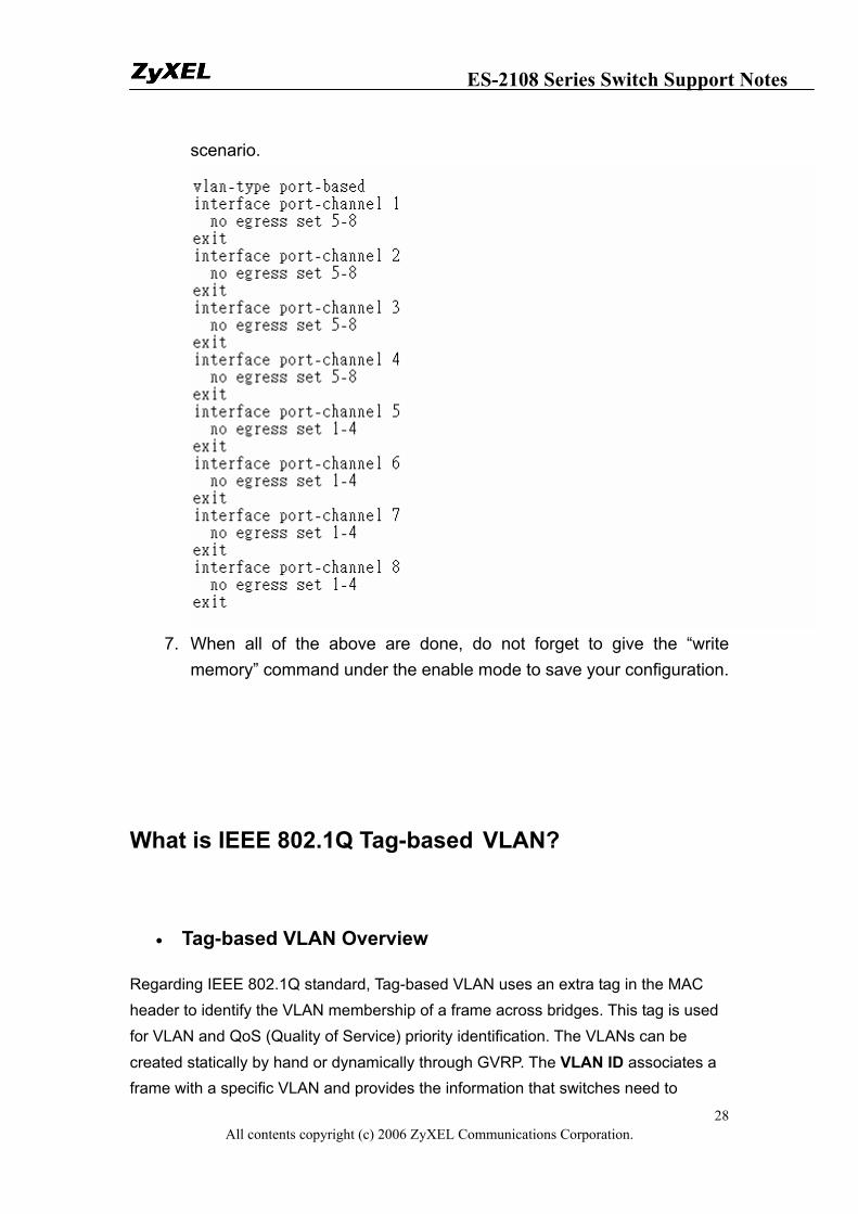
5. Put “en” or “enable” to go into the privileged mode. Then put “config” to go into the configuration mode.
6. Put the following commands to setup Port Based VLAN on the ES-2108-LC Switch in this
ES-2108 Series Switch Support Notes
All contents copyright (c) 2006 ZyXEL Communications Corporation. 28
scenario.
7. When all of the above are done, do not forget to give the “write
memory” command under the enable mode to save your configuration.
What is IEEE 802.1Q Tag-based VLAN?
• Tag-based VLAN Overview
Regarding IEEE 802.1Q standard, Tag-based VLAN uses an extra tag in the MAC header to identify the VLAN membership of a frame across bridges. This tag is used for VLAN and QoS (Quality of Service) priority identification. The VLANs can be created statically by hand or dynamically through GVRP. The VLAN ID associates a frame with a specific VLAN and provides the information that switches need to
ES-2108 Series Switch Support Notes
All contents copyright (c) 2006 ZyXEL Communications Corporation. 29
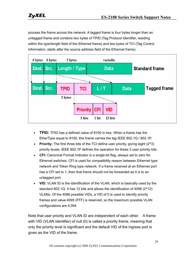
process the frame across the network. A tagged frame is four bytes longer than an untagged frame and contains two bytes of TPID (Tag Protocol Identifier, residing within the type/length field of the Ethernet frame) and two bytes of TCI (Tag Control Information, starts after the source address field of the Ethernet frame).
• TPID: TPID has a defined value of 8100 in hex. When a frame has the EtherType equal to 8100, this frame carries the tag IEEE 802.1Q / 802.1P.
• Priority: The first three bits of the TCI define user priority, giving eight (2^3) priority levels. IEEE 802.1P defines the operation for these 3 user priority bits.
• CFI: Canonical Format Indicator is a single-bit flag, always set to zero for Ethernet switches. CFI is used for compatibility reason between Ethernet type network and Token Ring type network. If a frame received at an Ethernet port has a CFI set to 1, then that frame should not be forwarded as it is to an untagged port.
• VID: VLAN ID is the identification of the VLAN, which is basically used by the standard 802.1Q. It has 12 bits and allows the identification of 4096 (2^12) VLANs. Of the 4096 possible VIDs, a VID of 0 is used to identify priority frames and value 4095 (FFF) is reserved, so the maximum possible VLAN configurations are 4,094.
Note that user priority and VLAN ID are independent of each other. A frame with VID (VLAN Identifier) of null (0) is called a priority frame, meaning that only the priority level is significant and the default VID of the ingress port is given as the VID of the frame.
ES-2108 Series Switch Support Notes
All contents copyright (c) 2006 ZyXEL Communications Corporation. 30
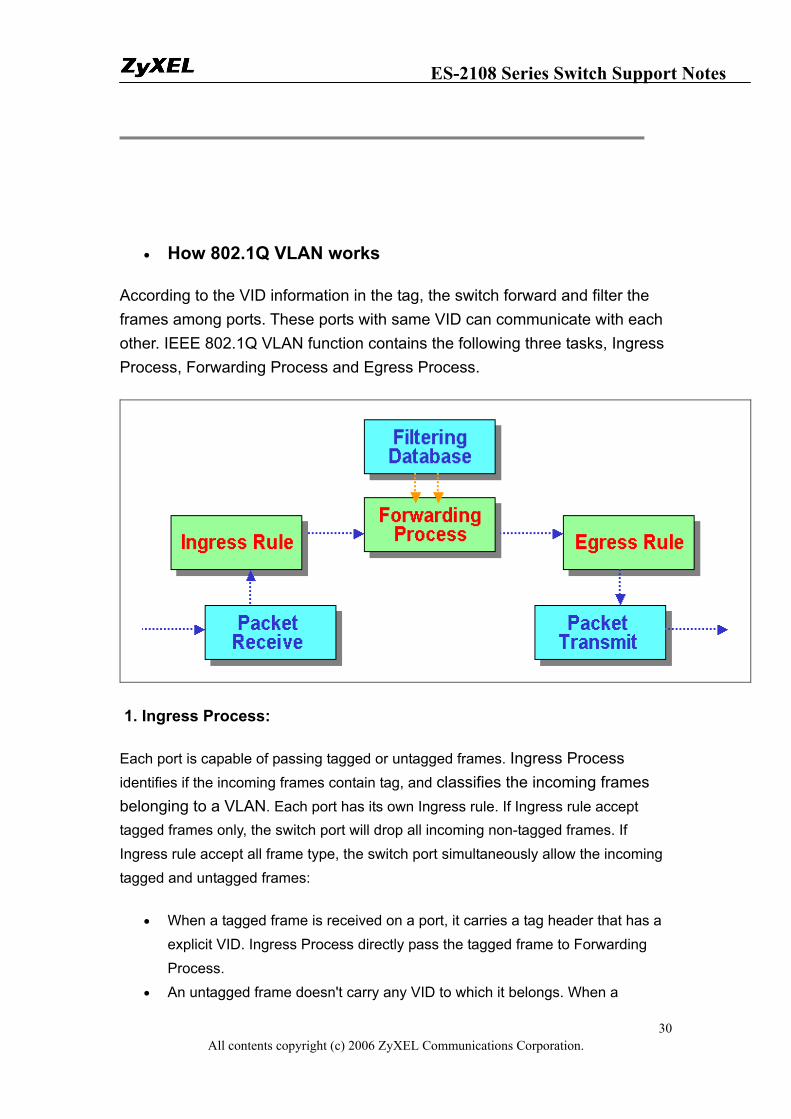
• How 802.1Q VLAN works
According to the VID information in the tag, the switch forward and filter the frames among ports. These ports with same VID can communicate with each other. IEEE 802.1Q VLAN function contains the following three tasks, Ingress Process, Forwarding Process and Egress Process.
1. Ingress Process:
Each port is capable of passing tagged or untagged frames. Ingress Process identifies if the incoming frames contain tag, and classifies the incoming frames belonging to a VLAN. Each port has its own Ingress rule. If Ingress rule accept tagged frames only, the switch port will drop all incoming non-tagged frames. If Ingress rule accept all frame type, the switch port simultaneously allow the incoming tagged and untagged frames:
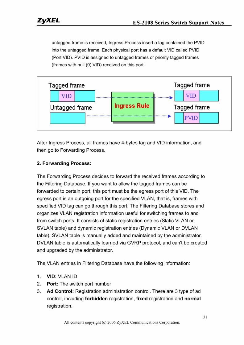
• When a tagged frame is received on a port, it carries a tag header that has a explicit VID. Ingress Process directly pass the tagged frame to Forwarding Process.
• An untagged frame doesn't carry any VID to which it belongs. When a
ES-2108 Series Switch Support Notes
All contents copyright (c) 2006 ZyXEL Communications Corporation. 31
untagged frame is received, Ingress Process insert a tag contained the PVID into the untagged frame. Each physical port has a default VID called PVID (Port VID). PVID is assigned to untagged frames or priority tagged frames (frames with null (0) VID) received on this port.
After Ingress Process, all frames have 4-bytes tag and VID information, and then go to Forwarding Process.
2. Forwarding Process:
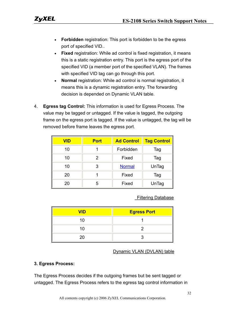
The Forwarding Process decides to forward the received frames according to the Filtering Database. If you want to allow the tagged frames can be forwarded to certain port, this port must be the egress port of this VID. The egress port is an outgoing port for the specified VLAN, that is, frames with specified VID tag can go through this port. The Filtering Database stores and organizes VLAN registration information useful for switching frames to and from switch ports. It consists of static registration entries (Static VLAN or SVLAN table) and dynamic registration entries (Dynamic VLAN or DVLAN table). SVLAN table is manually added and maintained by the administrator. DVLAN table is automatically learned via GVRP protocol, and can't be created and upgraded by the administrator.
The VLAN entries in Filtering Database have the following information:
1. VID: VLAN ID 2. Port: The switch port number 3. Ad Control: Registration administration control. There are 3 type of ad
control, including forbidden registration, fixed registration and normal registration.
ES-2108 Series Switch Support Notes
All contents copyright (c) 2006 ZyXEL Communications Corporation. 32
• Forbidden registration: This port is forbidden to be the egress port of specified VID..
• Fixed registration: While ad control is fixed registration, it means this is a static registration entry. This port is the egress port of the specified VID (a member port of the specified VLAN). The frames with specified VID tag can go through this port.
• Normal registration: While ad control is normal registration, it means this is a dynamic registration entry. The forwarding decision is depended on Dynamic VLAN table.
4. Egress tag Control: This information is used for Egress Process. The value may be tagged or untagged. If the value is tagged, the outgoing frame on the egress port is tagged. If the value is untagged, the tag will be removed before frame leaves the egress port.
VID Port Ad Control Tag Control
10 1 Forbidden Tag
10 2 Fixed Tag
10 3 Normal UnTag
20 1 Fixed Tag
20 5 Fixed UnTag
Filtering Database
VID Egress Port
10 1
10 2
20 3
Dynamic VLAN (DVLAN) table
3. Egress Process:
The Egress Process decides if the outgoing frames but be sent tagged or untagged. The Egress Process refers to the egress tag control information in
ES-2108 Series Switch Support Notes
All contents copyright (c) 2006 ZyXEL Communications Corporation. 33
Filtering Database. If the value is tagged, the outgoing frame on the egress port is tagged. If the value is untagged, the tag will be removed before frame leaves the egress port.
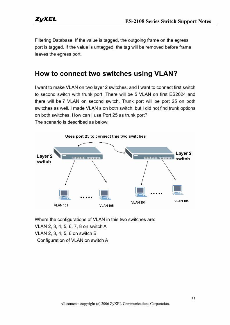
How to connect two switches using VLAN?
I want to make VLAN on two layer 2 switches, and I want to connect first switch to second switch with trunk port. There will be 5 VLAN on first ES2024 and there will be 7 VLAN on second switch. Trunk port will be port 25 on both switches as well. I made VLAN s on both switch, but I did not find trunk options on both switches. How can I use Port 25 as trunk port? The scenario is described as below:
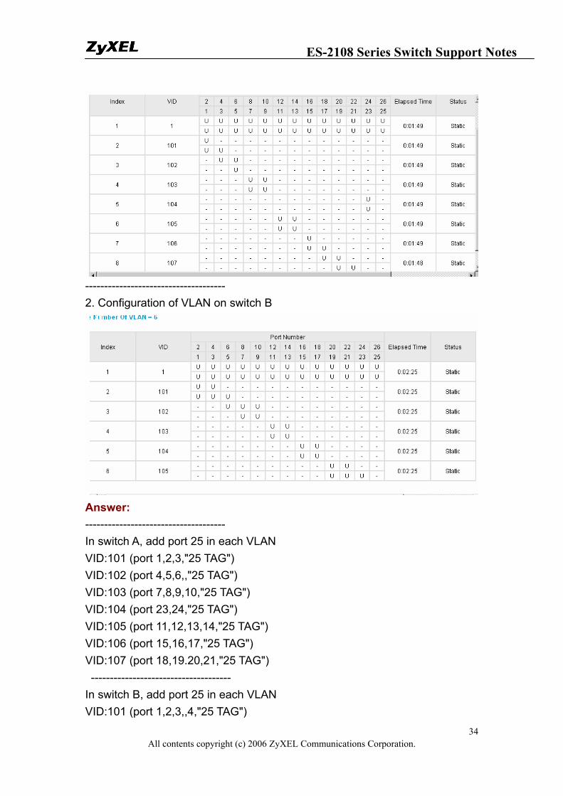
Where the configurations of VLAN in this two switches are: VLAN 2, 3, 4, 5, 6, 7, 8 on switch A VLAN 2, 3, 4, 5, 6 on switch B Configuration of VLAN on switch A
ES-2108 Series Switch Support Notes
All contents copyright (c) 2006 ZyXEL Communications Corporation. 34
------------------------------------- 2. Configuration of VLAN on switch B
Answer: ------------------------------------- In switch A, add port 25 in each VLAN VID:101 (port 1,2,3,"25 TAG") VID:102 (port 4,5,6,,"25 TAG") VID:103 (port 7,8,9,10,"25 TAG") VID:104 (port 23,24,"25 TAG") VID:105 (port 11,12,13,14,"25 TAG") VID:106 (port 15,16,17,"25 TAG") VID:107 (port 18,19.20,21,"25 TAG") ------------------------------------- In switch B, add port 25 in each VLAN VID:101 (port 1,2,3,,4,"25 TAG")
ES-2108 Series Switch Support Notes
All contents copyright (c) 2006 ZyXEL Communications Corporation. 35
VID:102 (port 6,7,8,9,10,"25 TAG") VID:103 (port 11,12,13,14,"25 TAG") VID:104 (port 15,16,17,18,"25 TAG") VID:105 (port 19,20,21,23,22"25 TAG) Clients in same VLAN on both switches can communicate each other. PVID:
Set PVID on switch 1 Port 1, 2, 3 : 101 Port 4, 5, 6 : 102 Port 7, 8, 9, 10 : 103 Port 23, 24: 104 Port 11, 12, 13, 14: 105 Port 15, 16, 17: 106 Port 18, 19, 20, 21: 107 port 25: PVID=any
Set PVID on switch 2: Port 1, 2, 3, 4 : 101 Port 6, 7, 8, 9, 10, : 102 Port 11, 12, 13, 14, : 103 Port 15, 16, 17, 18: 104 Port 19, 20, 21, 22, 23: 105 Port 25:PVID=any
ES-2108 Series Switch Support Notes
All contents copyright (c) 2006 ZyXEL Communications Corporation. 36
To ring a network by building reducdent links and connections between Switch
What is Spanning Tree Protocol
• Spanning Tree Overview
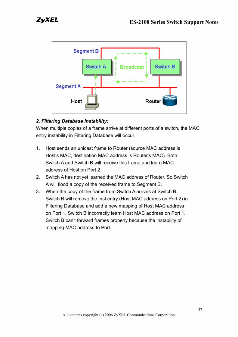
Spanning-Tree Protocol (STP) is a Layer 2 protocol designed to run on bridges and switches. The specification for STP is defined in IEEE 802.1d. The main purpose of STP is to ensure that you do not run into a loop situation when you have redundant paths in your network. STP detects/disables network loops and provides backup links between switches or bridges. It allows the device to interact with other STP compliant devices in your network to ensure that only one path exists between any two stations on the network. The redundant topology without STP will cause the following problem: 1. Broadcast storm: Without Spanning Tree loop avoidance mechanism, each switch will endlessly flood broadcast packets to all ports. This situation is called broadcast storm.
1. When Host sends a broadcast frame, like an ARP request to Router, the frame will be received by Switch A.
2. Switch A identify the destination MAC address field (broadcast FF:FF:FF:FF:FF:FF) in the frame and determine to flood it onto Segment B.
3. When the broadcast frame arrives at Switch B, Switch will repeat above process, flood it to Segment A.
4. The broadcast frame will endlessly travel around the loop network even Router has already received this frame.
ES-2108 Series Switch Support Notes
All contents copyright (c) 2006 ZyXEL Communications Corporation. 37
2. Filtering Database Instability: When multiple copies of a frame arrive at different ports of a switch, the MAC entry instability in Filtering Database will occur.
1. Host sends an unicast frame to Router (source MAC address is Host's MAC, destination MAC address is Router's MAC). Both Switch A and Switch B will receive this frame and learn MAC address of Host on Port 2.
2. Switch A has not yet learned the MAC address of Router. So Switch A will flood a copy of the received frame to Segment B.
3. When the copy of the frame from Switch A arrives at Switch B, Switch B will remove the first entry (Host MAC address on Port 2) in Filtering Database and add a new mapping of Host MAC address on Port 1. Switch B incorrectly learn Host MAC address on Port 1. Switch B can't forward frames properly because the instability of mapping MAC address to Port.
ES-2108 Series Switch Support Notes
All contents copyright (c) 2006 ZyXEL Communications Corporation. 38
How STP Works
Spanning Tree provide a loop-free network. When a switch supported STP recognize a loop in the network topology, it blocks one or more redundant ports. Spanning Tree Protocol continually explore the network, so when the network topology changes, STP automatically reconfigure switch ports to avoid the failure by blocking certain port. Spanning tree algorithm aware switches (bridges) exchange configuration messages periodically. The configuration message is a multicast frame called BPDU (Bridge Protocol Data Unit) or Hello message. According to BPDU, these STP aware will construct a loop free network with "tree" architecture. STP operation is listed as the following: 1. Select a root bridge Only one switch/ bridge can be selected as the root bridge in a given network. All other decisions in the network, such as which port is blocked and which port is put in forwarding mode, are made regarding this root bridge. The root bridge is the "root" of the constructed "tree".
1. One of the important field included in the BPDU is the bridge ID. Each bridge has unique bridge ID. The root bridge is the bridge with the lowest bridge ID in the spanning tree network.
ES-2108 Series Switch Support Notes
All contents copyright (c) 2006 ZyXEL Communications Corporation. 39
2. The bridge ID includes two parts, bridge priority (2 bytes) and bridge MAC address (6 bytes). The 802.1d default bridge priority is 32768. For example, a switch with default priority 32768 (8000 hex), MAC address is 00:A0:C5:12:34:56, its bridge ID is 8000:00A0:C512:3456.
3. On the root bridge, all its ports are designated ports. Designated ports are always in the forwarding state. While in forwarding state, a port can receive and send traffic.
2. Select a root port for the non-root bridge For the non-root switch/bridge, there will be one root port. The root port is the port through which this non-root switch / bridge communicates with the root bridge (the "leaf" side of the "tree").
1. The root port is the port on the non-root bridge with the lowest path cost to the root bridge. The root port is normally in forwarding state.
2. Path cost is the total cost of transmitting a frame on to a LAN through that port to bridge root. It is assigned according to the bandwidth of the link. The slower the media, the higher the cost. Some of the path costs specified in the IEEE 802.1d specification are listed below.
Link Speed Recommended
Cost Recommended
Cost Range
4Mbps 250 100 to 1000
10Mbps 100 50 to 600
16Mbps 62 40 to 400
100Mbps 19 10 to 60
1Gbps 4 3 to 10
10Gbps 2 1 to 5
3. When multiple ports have the same path cost to root bridge, the port with lowest port priority is selected as root port.
3. Select a designated port on each segment
ES-2108 Series Switch Support Notes
All contents copyright (c) 2006 ZyXEL Communications Corporation. 40
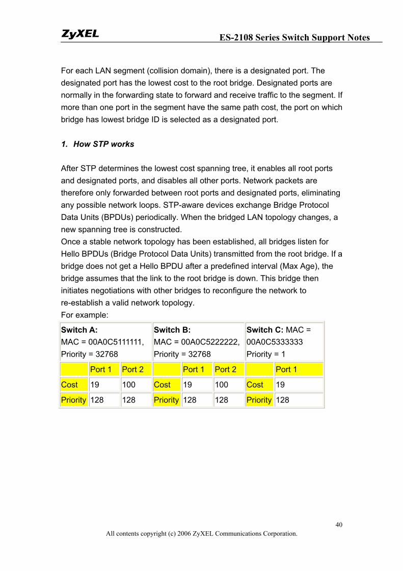
For each LAN segment (collision domain), there is a designated port. The designated port has the lowest cost to the root bridge. Designated ports are normally in the forwarding state to forward and receive traffic to the segment. If more than one port in the segment have the same path cost, the port on which bridge has lowest bridge ID is selected as a designated port. 1. How STP works After STP determines the lowest cost spanning tree, it enables all root ports and designated ports, and disables all other ports. Network packets are therefore only forwarded between root ports and designated ports, eliminating any possible network loops. STP-aware devices exchange Bridge Protocol Data Units (BPDUs) periodically. When the bridged LAN topology changes, a new spanning tree is constructed. Once a stable network topology has been established, all bridges listen for Hello BPDUs (Bridge Protocol Data Units) transmitted from the root bridge. If a bridge does not get a Hello BPDU after a predefined interval (Max Age), the bridge assumes that the link to the root bridge is down. This bridge then initiates negotiations with other bridges to reconfigure the network to re-establish a valid network topology. For example:
Switch A: MAC = 00A0C5111111, Priority = 32768
Switch B: MAC = 00A0C5222222, Priority = 32768
Switch C: MAC = 00A0C5333333 Priority = 1
Port 1 Port 2 Port 1 Port 2 Port 1
Cost 19 100 Cost 19 100 Cost 19
Priority 128 128 Priority 128 128 Priority 128
ES-2108 Series Switch Support Notes
All contents copyright (c) 2006 ZyXEL Communications Corporation. 41
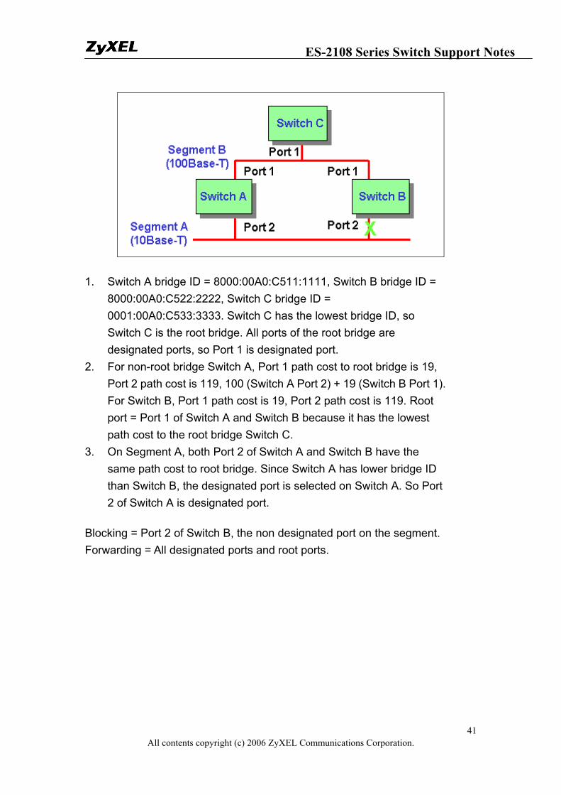
1. Switch A bridge ID = 8000:00A0:C511:1111, Switch B bridge ID = 8000:00A0:C522:2222, Switch C bridge ID = 0001:00A0:C533:3333. Switch C has the lowest bridge ID, so Switch C is the root bridge. All ports of the root bridge are designated ports, so Port 1 is designated port.
2. For non-root bridge Switch A, Port 1 path cost to root bridge is 19, Port 2 path cost is 119, 100 (Switch A Port 2) + 19 (Switch B Port 1). For Switch B, Port 1 path cost is 19, Port 2 path cost is 119. Root port = Port 1 of Switch A and Switch B because it has the lowest path cost to the root bridge Switch C.
3. On Segment A, both Port 2 of Switch A and Switch B have the same path cost to root bridge. Since Switch A has lower bridge ID than Switch B, the designated port is selected on Switch A. So Port 2 of Switch A is designated port.
Blocking = Port 2 of Switch B, the non designated port on the segment. Forwarding = All designated ports and root ports.
ES-2108 Series Switch Support Notes
All contents copyright (c) 2006 ZyXEL Communications Corporation. 42
Switching security
MAC freeze
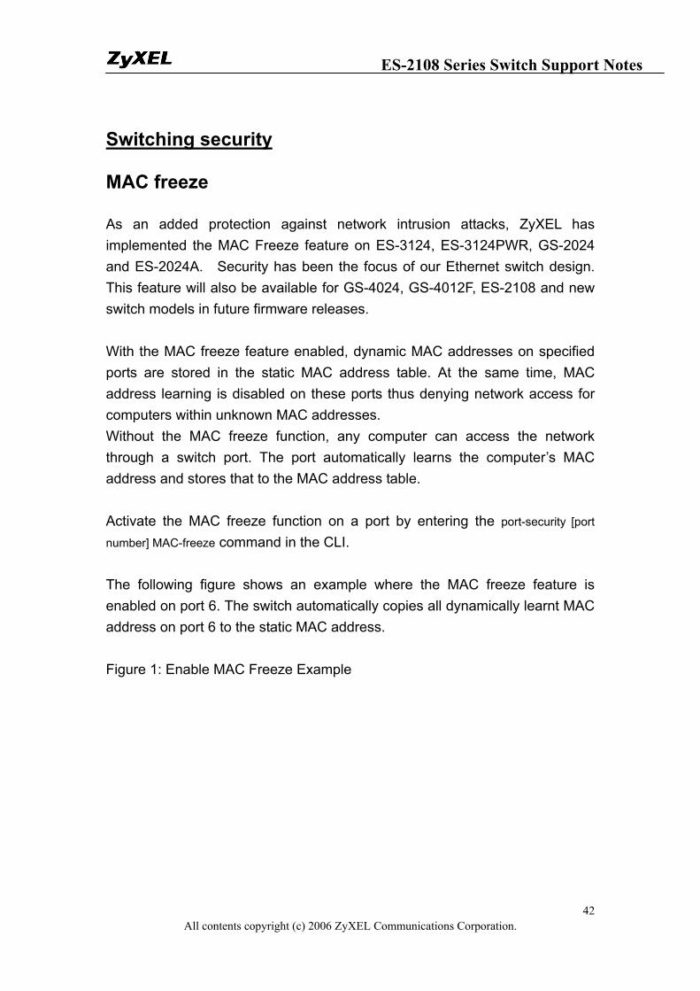
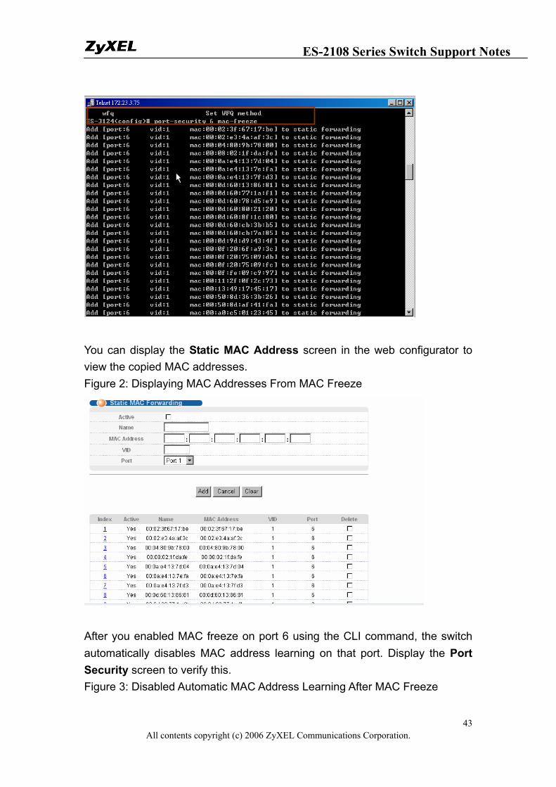
As an added protection against network intrusion attacks, ZyXEL has implemented the MAC Freeze feature on ES-3124, ES-3124PWR, GS-2024 and ES-2024A. Security has been the focus of our Ethernet switch design. This feature will also be available for GS-4024, GS-4012F, ES-2108 and new switch models in future firmware releases. With the MAC freeze feature enabled, dynamic MAC addresses on specified ports are stored in the static MAC address table. At the same time, MAC address learning is disabled on these ports thus denying network access for computers within unknown MAC addresses. Without the MAC freeze function, any computer can access the network through a switch port. The port automatically learns the computer’s MAC address and stores that to the MAC address table. Activate the MAC freeze function on a port by entering the port-security [port
number] MAC-freeze command in the CLI. The following figure shows an example where the MAC freeze feature is enabled on port 6. The switch automatically copies all dynamically learnt MAC address on port 6 to the static MAC address. Figure 1: Enable MAC Freeze Example
ES-2108 Series Switch Support Notes
All contents copyright (c) 2006 ZyXEL Communications Corporation. 43
You can display the Static MAC Address screen in the web configurator to view the copied MAC addresses. Figure 2: Displaying MAC Addresses From MAC Freeze
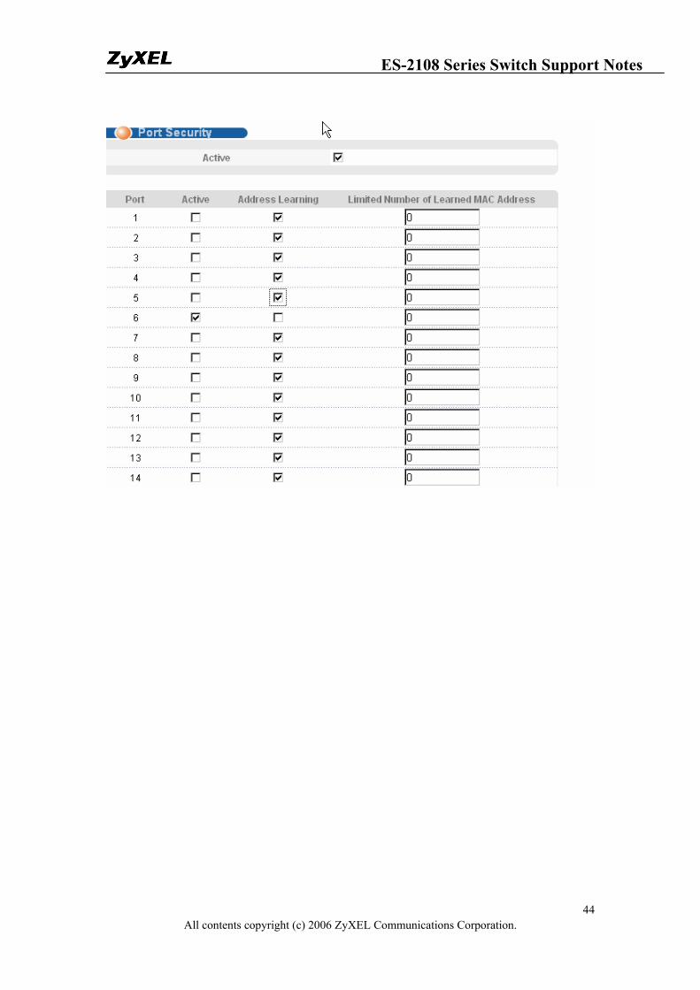
After you enabled MAC freeze on port 6 using the CLI command, the switch automatically disables MAC address learning on that port. Display the Port Security screen to verify this. Figure 3: Disabled Automatic MAC Address Learning After MAC Freeze
ES-2108 Series Switch Support Notes
All contents copyright (c) 2006 ZyXEL Communications Corporation. 44
ES-2108 Series Switch Support Notes
All contents copyright (c) 2006 ZyXEL Communications Corporation. 45
Centralized Management
Introduction of SNMPc and NetAtlas
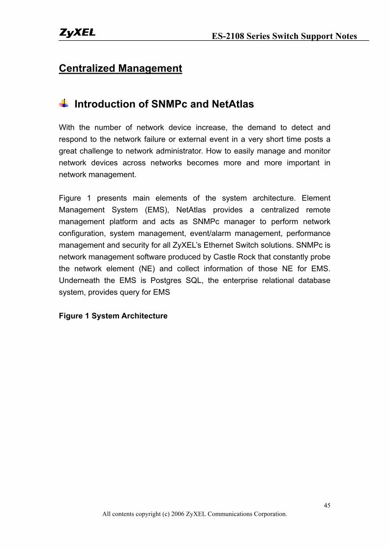
With the number of network device increase, the demand to detect and respond to the network failure or external event in a very short time posts a great challenge to network administrator. How to easily manage and monitor network devices across networks becomes more and more important in network management. Figure 1 presents main elements of the system architecture. Element Management System (EMS), NetAtlas provides a centralized remote management platform and acts as SNMPc manager to perform network configuration, system management, event/alarm management, performance management and security for all ZyXEL’s Ethernet Switch solutions. SNMPc is network management software produced by Castle Rock that constantly probe the network element (NE) and collect information of those NE for EMS. Underneath the EMS is Postgres SQL, the enterprise relational database system, provides query for EMS Figure 1 System Architecture
ES-2108 Series Switch Support Notes
All contents copyright (c) 2006 ZyXEL Communications Corporation. 46
Overview of SNMPc
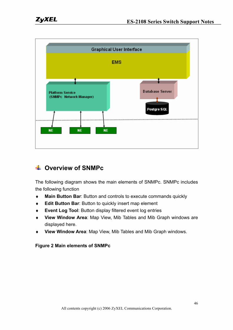
The following diagram shows the main elements of SNMPc. SNMPc includes the following function ♦ Main Button Bar: Button and controls to execute commands quickly ♦ Edit Button Bar: Button to quickly insert map element ♦ Event Log Tool: Button display filtered event log entries ♦ View Window Area: Map View, Mib Tables and Mib Graph windows are
displayed here. ♦ View Window Area: Map View, Mib Tables and Mib Graph windows. Figure 2 Main elements of SNMPc
ES-2108 Series Switch Support Notes
All contents copyright (c) 2006 ZyXEL Communications Corporation. 47
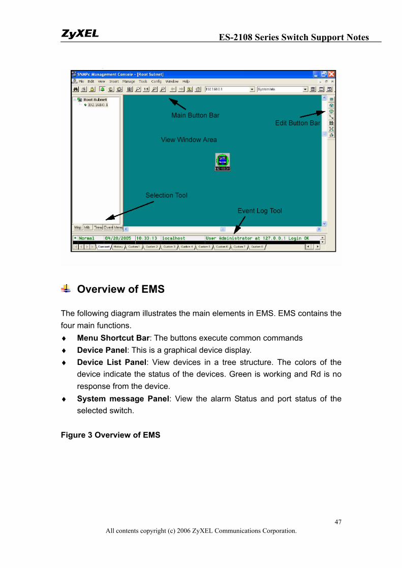
Overview of EMS
The following diagram illustrates the main elements in EMS. EMS contains the four main functions. ♦ Menu Shortcut Bar: The buttons execute common commands ♦ Device Panel: This is a graphical device display. ♦ Device List Panel: View devices in a tree structure. The colors of the
device indicate the status of the devices. Green is working and Rd is no response from the device.
♦ System message Panel: View the alarm Status and port status of the selected switch.
Figure 3 Overview of EMS

ES-2108 Series Switch Support Notes
All contents copyright (c) 2006 ZyXEL Communications Corporation. 48
Configuration of adding a new device via SNMPc
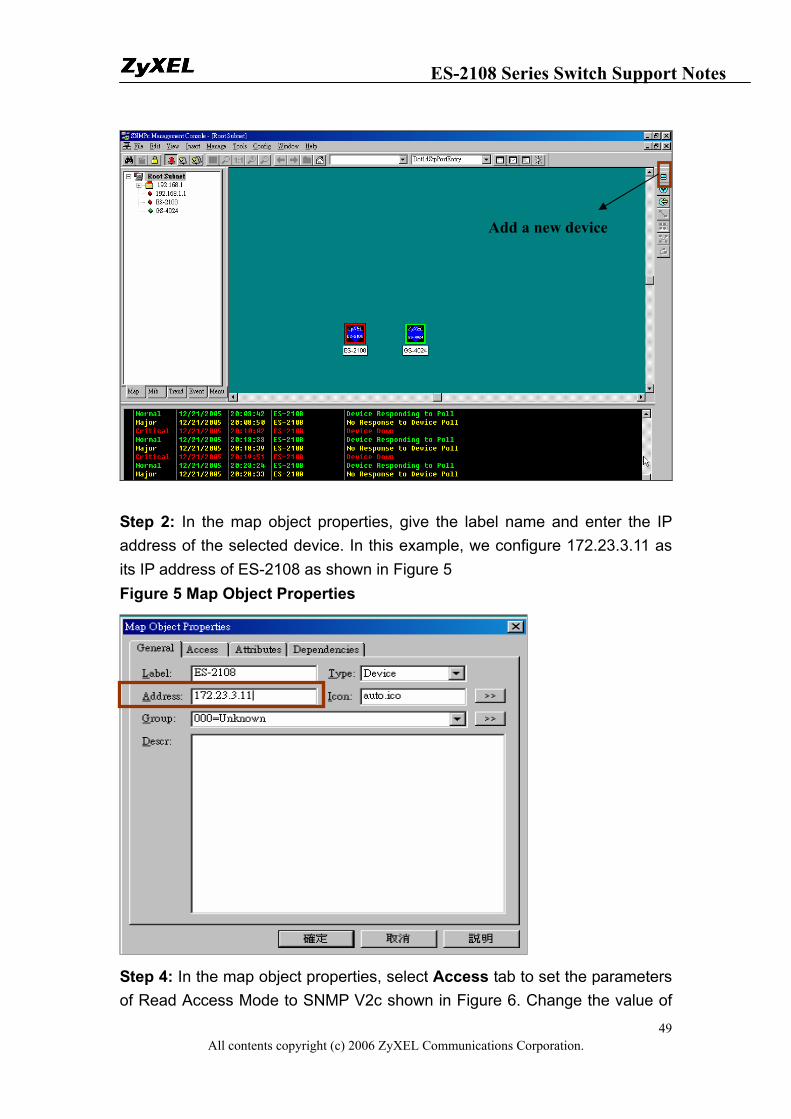
In the following example, we will illustrate how to get started with SNMPc and Netatlas with adding a new device. Follow the procedures from Step 1 to Step 11. Step 1: In the edit button bar shown in the Figure 4 where you may select the icon to insert a new element. Figure 4 Adding a new Device
ES-2108 Series Switch Support Notes
All contents copyright (c) 2006 ZyXEL Communications Corporation. 49
Step 2: In the map object properties, give the label name and enter the IP address of the selected device. In this example, we configure 172.23.3.11 as its IP address of ES-2108 as shown in Figure 5 Figure 5 Map Object Properties
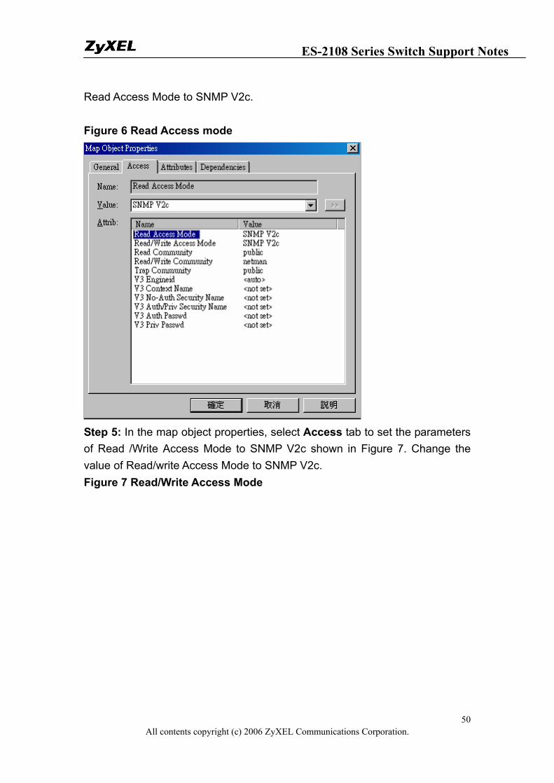
Step 4: In the map object properties, select Access tab to set the parameters of Read Access Mode to SNMP V2c shown in Figure 6. Change the value of
Add a new device
ES-2108 Series Switch Support Notes
All contents copyright (c) 2006 ZyXEL Communications Corporation. 50
Read Access Mode to SNMP V2c. Figure 6 Read Access mode
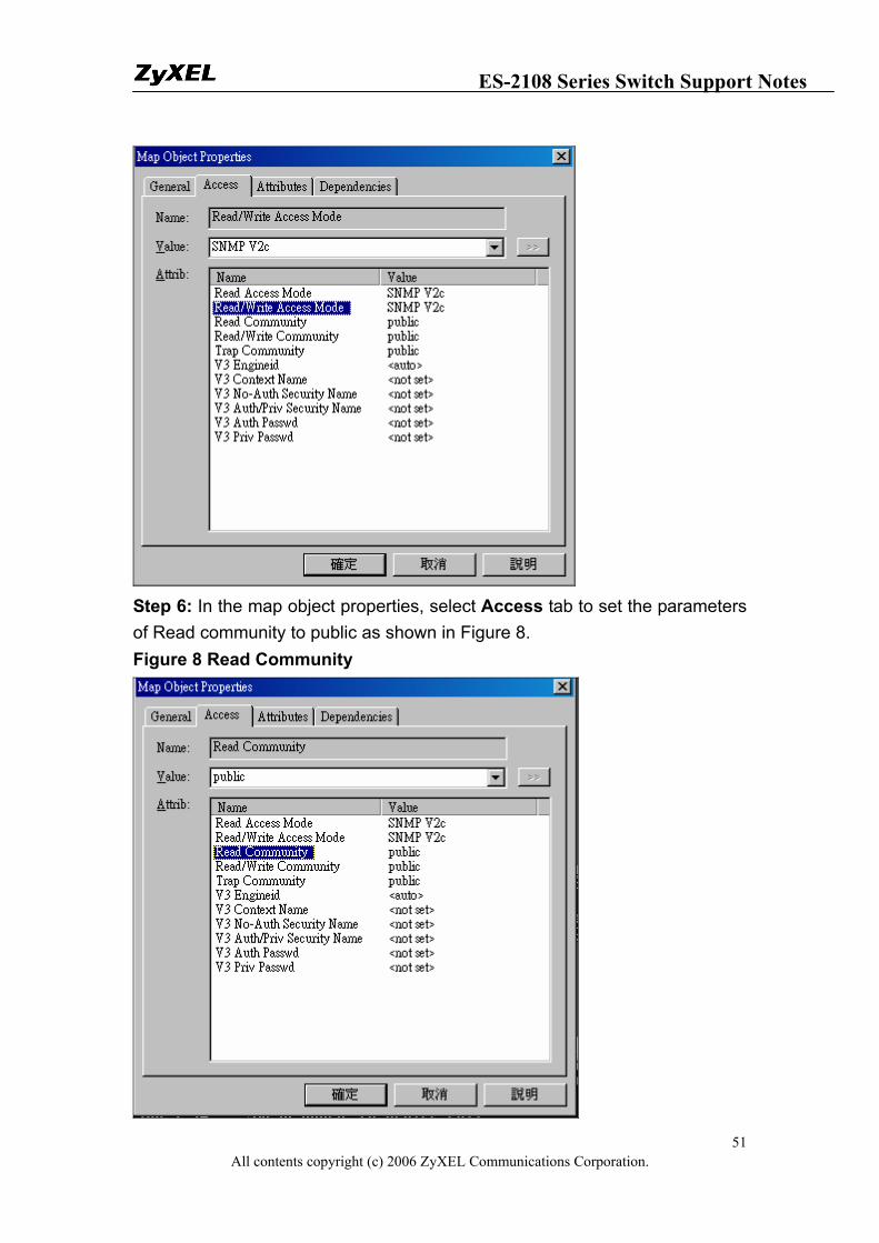
Step 5: In the map object properties, select Access tab to set the parameters of Read /Write Access Mode to SNMP V2c shown in Figure 7. Change the value of Read/write Access Mode to SNMP V2c. Figure 7 Read/Write Access Mode
ES-2108 Series Switch Support Notes
All contents copyright (c) 2006 ZyXEL Communications Corporation. 51
Step 6: In the map object properties, select Access tab to set the parameters of Read community to public as shown in Figure 8. Figure 8 Read Community
ES-2108 Series Switch Support Notes
All contents copyright (c) 2006 ZyXEL Communications Corporation. 52
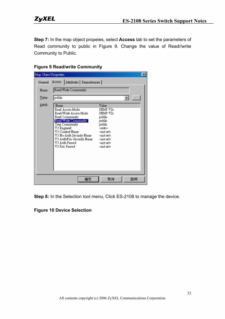
Step 7: In the map object propeies, select Access tab to set the parameters of Read community to public in Figure 9. Change the value of Read//write Community to Public. Figure 9 Read/write Community
Step 8: In the Selection tool menu, Click ES-2108 to manage the device. Figure 10 Device Selection
ES-2108 Series Switch Support Notes
All contents copyright (c) 2006 ZyXEL Communications Corporation. 53
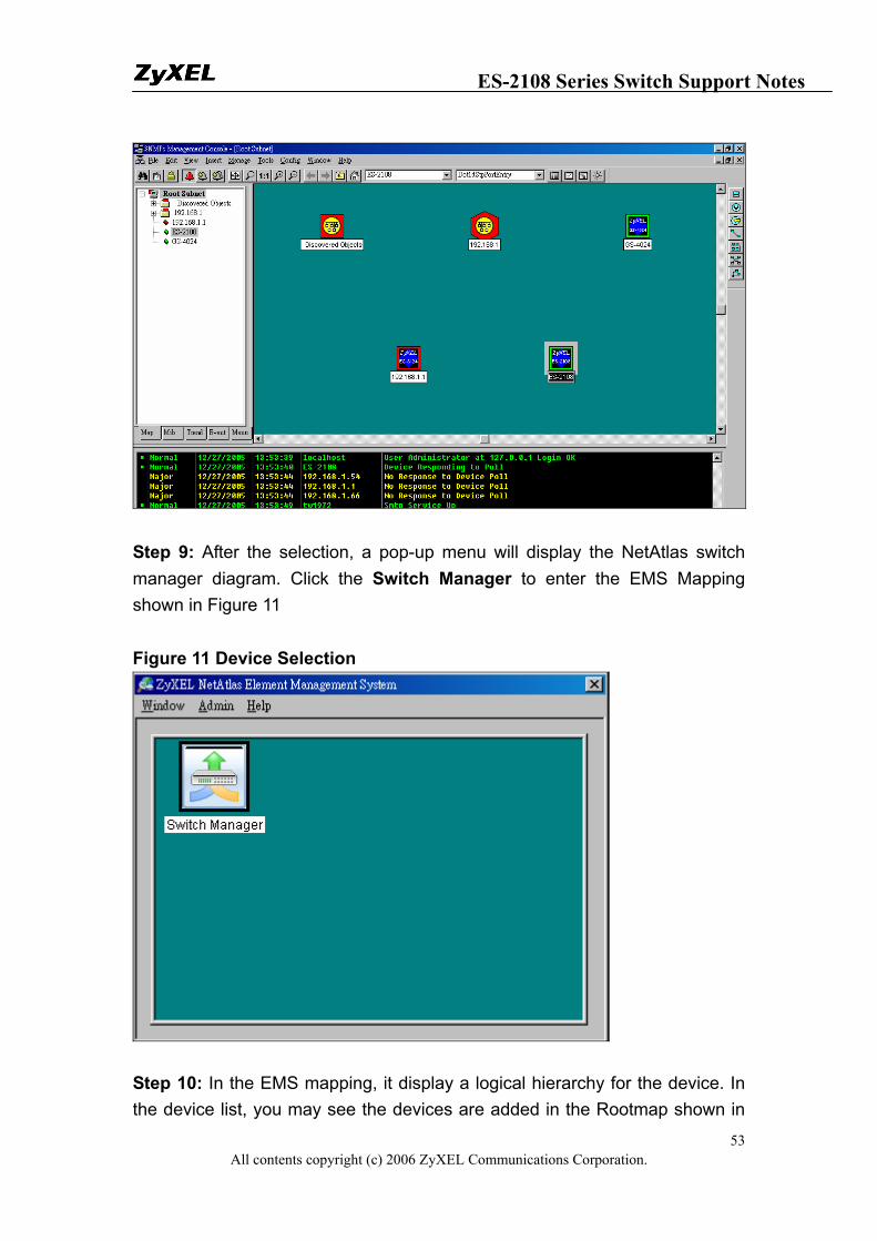
Step 9: After the selection, a pop-up menu will display the NetAtlas switch manager diagram. Click the Switch Manager to enter the EMS Mapping shown in Figure 11 Figure 11 Device Selection
Step 10: In the EMS mapping, it display a logical hierarchy for the device. In the device list, you may see the devices are added in the Rootmap shown in
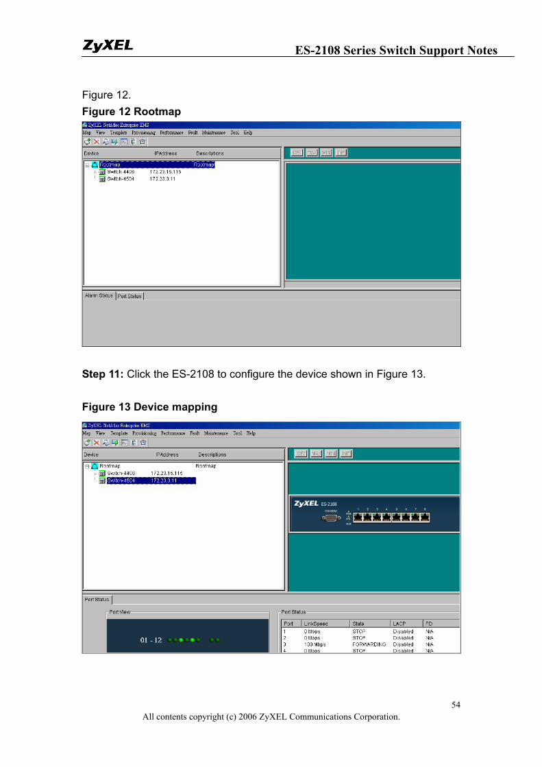
ES-2108 Series Switch Support Notes
All contents copyright (c) 2006 ZyXEL Communications Corporation. 54
Figure 12. Figure 12 Rootmap
Step 11: Click the ES-2108 to configure the device shown in Figure 13. Figure 13 Device mapping
ES-2108 Series Switch Support Notes
All contents copyright (c) 2006 ZyXEL Communications Corporation. 55
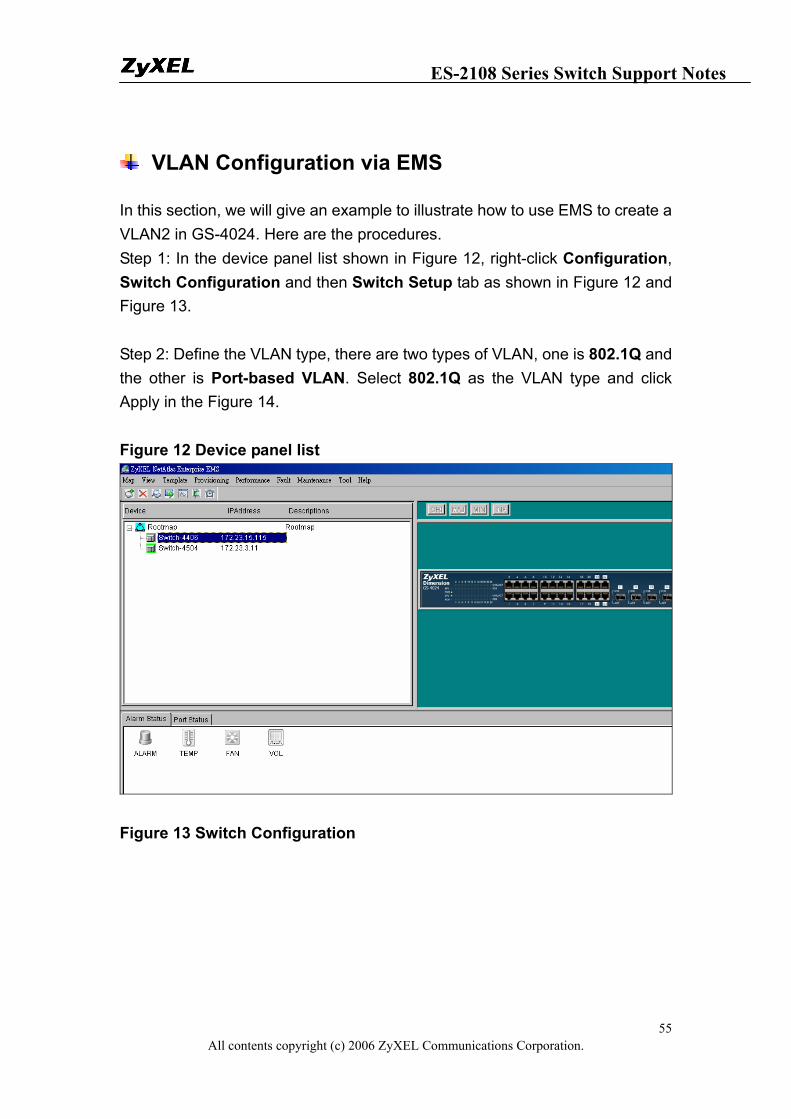
VLAN Configuration via EMS
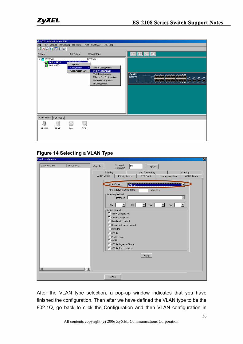
In this section, we will give an example to illustrate how to use EMS to create a VLAN2 in GS-4024. Here are the procedures. Step 1: In the device panel list shown in Figure 12, right-click Configuration, Switch Configuration and then Switch Setup tab as shown in Figure 12 and Figure 13. Step 2: Define the VLAN type, there are two types of VLAN, one is 802.1Q and the other is Port-based VLAN. Select 802.1Q as the VLAN type and click Apply in the Figure 14. Figure 12 Device panel list
Figure 13 Switch Configuration
ES-2108 Series Switch Support Notes
All contents copyright (c) 2006 ZyXEL Communications Corporation. 56
Figure 14 Selecting a VLAN Type
After the VLAN type selection, a pop-up window indicates that you have finished the configuration. Then after we have defined the VLAN type to be the 802.1Q, go back to click the Configuration and then VLAN configuration in
ES-2108 Series Switch Support Notes
All contents copyright (c) 2006 ZyXEL Communications Corporation. 57
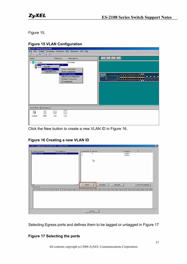
Figure 15. Figure 15 VLAN Configuration
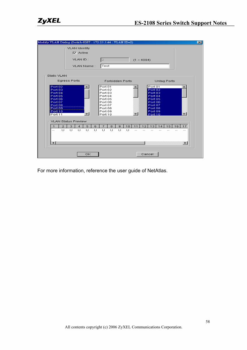
Click the New button to create a new VLAN ID in Figure 16. Figure 16 Creating a new VLAN ID
Selecting Egress ports and defines them to be tagged or untagged in Figure 17 Figure 17 Selecting the ports
ES-2108 Series Switch Support Notes
All contents copyright (c) 2006 ZyXEL Communications Corporation. 58
For more information, reference the user guide of NetAtlas.
ES-2108 Series Switch Support Notes
All contents copyright (c) 2006 ZyXEL Communications Corporation. 59
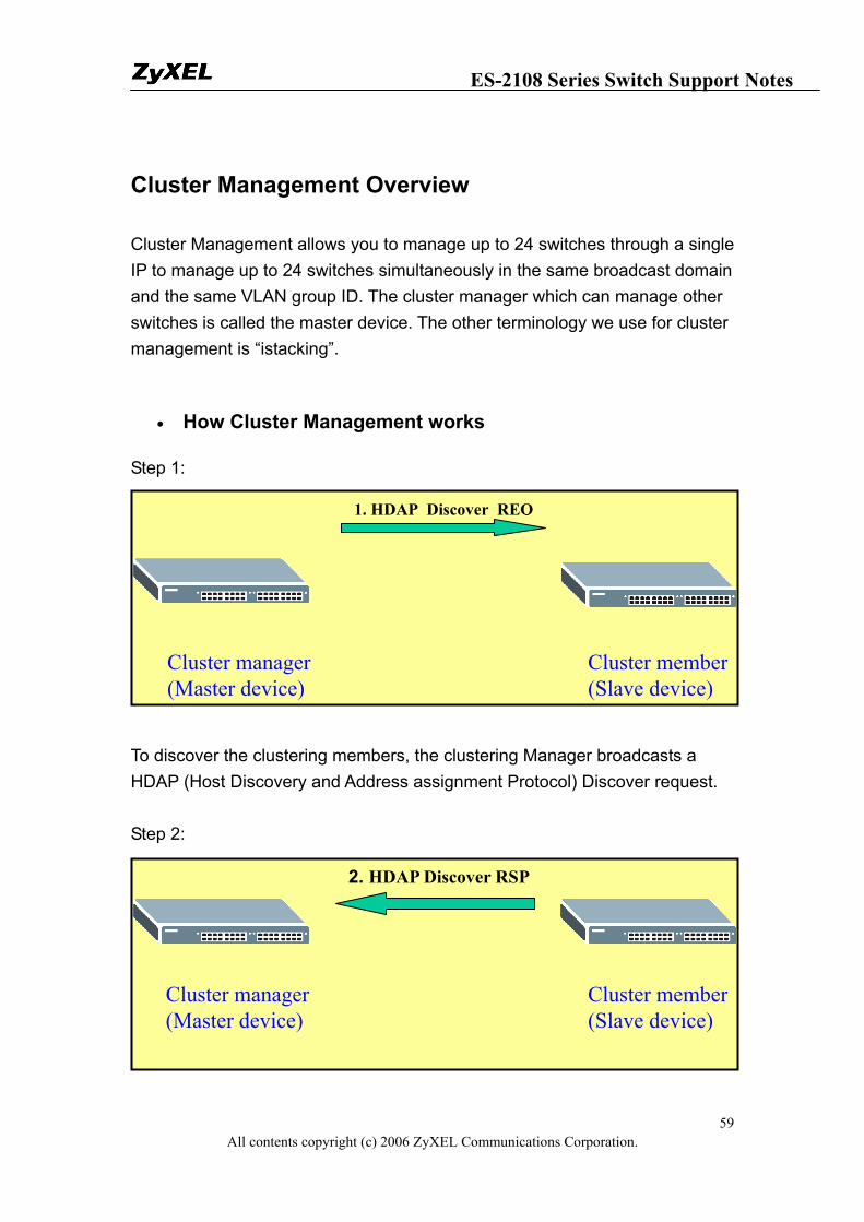
Cluster Management Overview
Cluster Management allows you to manage up to 24 switches through a single IP to manage up to 24 switches simultaneously in the same broadcast domain and the same VLAN group ID. The cluster manager which can manage other switches is called the master device. The other terminology we use for cluster management is “istacking”.
• How Cluster Management works
Step 1:
To discover the clustering members, the clustering Manager broadcasts a HDAP (Host Discovery and Address assignment Protocol) Discover request. Step 2:
Cluster manager (Master device)
1. HDAP Discover REQ
Cluster member(Slave device)
Cluster manager (Master device)
2. HDAP Discover RSP
Cluster member(Slave device)
ES-2108 Series Switch Support Notes
All contents copyright (c) 2006 ZyXEL Communications Corporation. 60
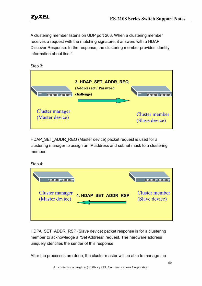
A clustering member listens on UDP port 263. When a clustering member receives a request with the matching signature, it answers with a HDAP Discover Response. In the response, the clustering member provides identity information about itself. Step 3:
HDAP_SET_ADDR_REQ (Master device) packet request is used for a clustering manager to assign an IP address and subnet mask to a clustering member. Step 4:
HDPA_SET_ADDR_RSP (Slave device) packet response is for a clustering member to acknowledge a "Set Address" request. The hardware address uniquely identifies the sender of this response. After the processes are done, the cluster master will be able to manage the
Cluster manager (Master device)
3. HDAP_SET_ADDR_REQ(Address set / Password challenge)
Cluster member(Slave device)
Cluster manager (Master device)
4. HDAP_SET_ADDR_RSP Cluster member(Slave device)
ES-2108 Series Switch Support Notes
All contents copyright (c) 2006 ZyXEL Communications Corporation. 61
slave switch.
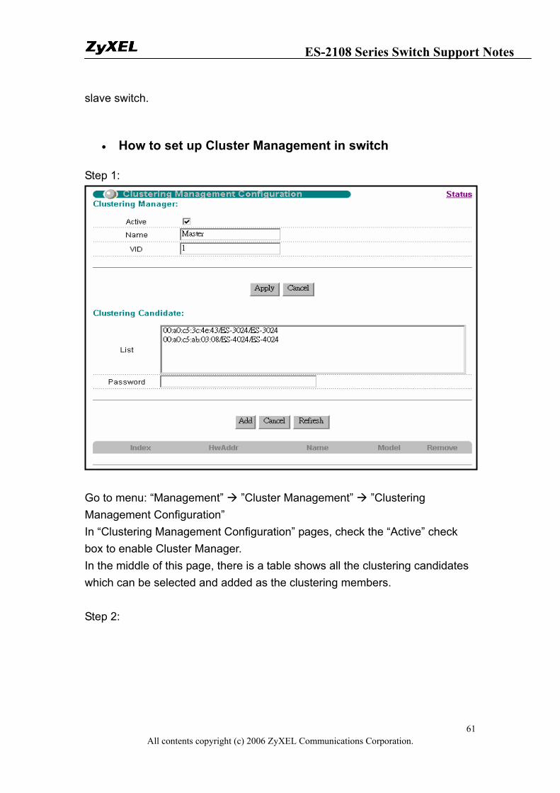
• How to set up Cluster Management in switch
Step 1:
Go to menu: “Management” ”Cluster Management” ”Clustering Management Configuration” In “Clustering Management Configuration” pages, check the “Active” check box to enable Cluster Manager. In the middle of this page, there is a table shows all the clustering candidates which can be selected and added as the clustering members. Step 2:
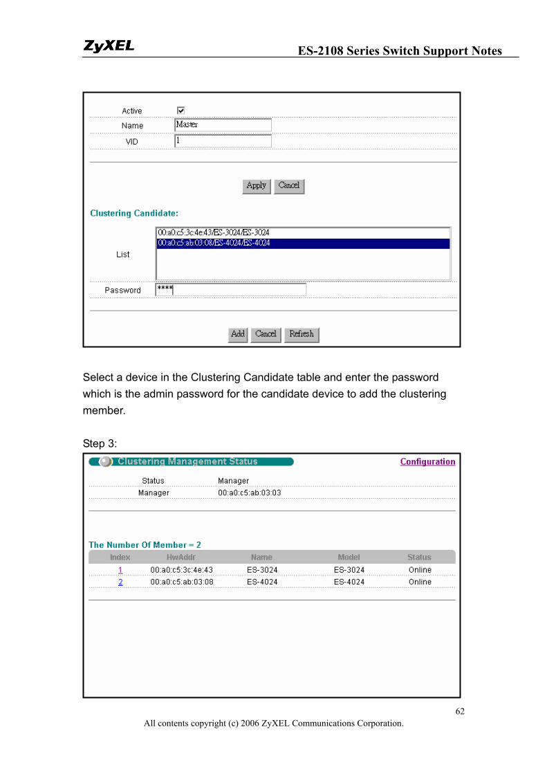
ES-2108 Series Switch Support Notes
All contents copyright (c) 2006 ZyXEL Communications Corporation. 62
Select a device in the Clustering Candidate table and enter the password which is the admin password for the candidate device to add the clustering member. Step 3:
ES-2108 Series Switch Support Notes
All contents copyright (c) 2006 ZyXEL Communications Corporation. 63
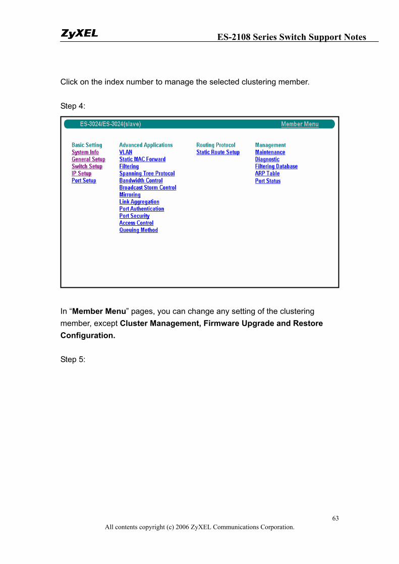
Click on the index number to manage the selected clustering member. Step 4:
In “Member Menu” pages, you can change any setting of the clustering member, except Cluster Management, Firmware Upgrade and Restore Configuration. Step 5:
ES-2108 Series Switch Support Notes
All contents copyright (c) 2006 ZyXEL Communications Corporation. 64
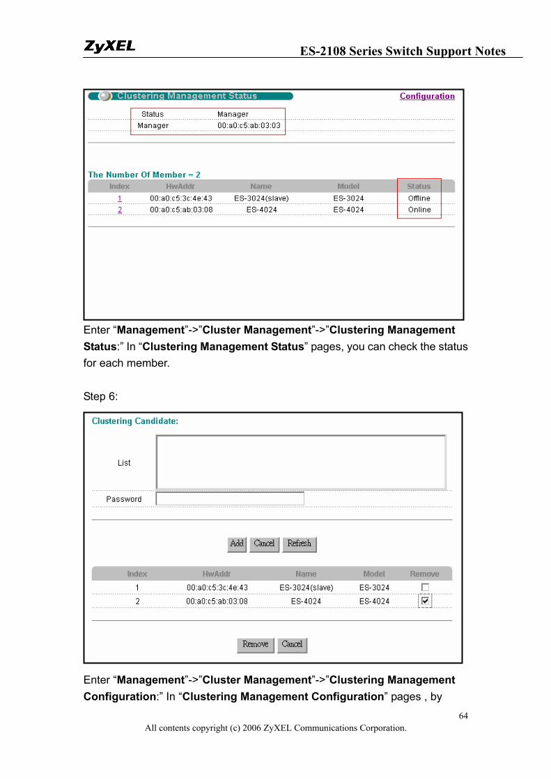
Enter “Management”->”Cluster Management”->”Clustering Management Status:” In “Clustering Management Status” pages, you can check the status for each member. Step 6:
Enter “Management”->”Cluster Management”->”Clustering Management Configuration:” In “Clustering Management Configuration” pages , by
ES-2108 Series Switch Support Notes
All contents copyright (c) 2006 ZyXEL Communications Corporation. 65
checking the remove checkbox and then, click on the Remove button to remove a cluster member. FAQ
What is ES-2108-LC?
The ES-2108-LC is a layer 2 stand-alone Ethernet switch with 8 10/100Mbps ports, one slots for mini GBIC transceivers, one 100FX Port and one console port for local management.
What is the default setting of the IP parameters?
IP address: 192.168.1.1 Subnet: 255.255.255.0
What is the default login Name and Password of the Web Configurator?
ID: admin Password: 1234
How to access my SWITCH through the console port?
Connect the male 9-pin end of the console cable to the console port of the Switch. Connect the female end to a serial port (COM1, COM2 or other COM port) of your computer, which has terminal emulation software configured to the follow parameters: Terminal emulation: VT100 Baud rate: 9600 bps Data bits: 8
ES-2108 Series Switch Support Notes
All contents copyright (c) 2006 ZyXEL Communications Corporation. 66
Parity: none Stop bit: 1 Flow control: none
What is default login password of the console, telnet, and FTP?
Password: 1234
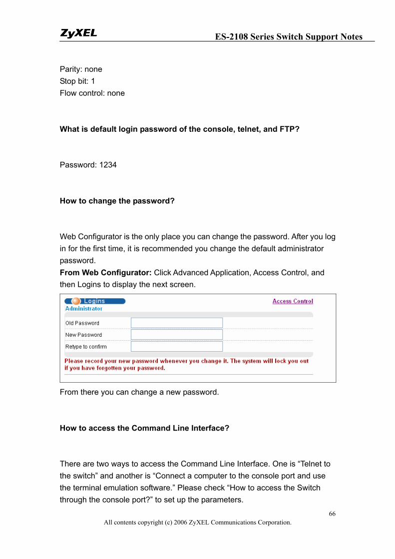
How to change the password?
Web Configurator is the only place you can change the password. After you log in for the first time, it is recommended you change the default administrator password. From Web Configurator: Click Advanced Application, Access Control, and then Logins to display the next screen.
From there you can change a new password.
How to access the Command Line Interface?
There are two ways to access the Command Line Interface. One is “Telnet to the switch” and another is “Connect a computer to the console port and use the terminal emulation software.” Please check “How to access the Switch through the console port?” to set up the parameters.
ES-2108 Series Switch Support Notes
All contents copyright (c) 2006 ZyXEL Communications Corporation. 67
If you forget the password, how to reset the password to default?
If you forget the password, you will need to reload the factory default configuration. Please be aware that you will lose all previous configurations. 1. Connect the console cable to your computer and open the terminal
emulation software. 2. Power off and then power on the Switch, and press any key to enter the
debug mode when the screen shows “Press any key to enter Debug Mode within 3 seconds.”
3. Type “atlc” and press the enter key 4. When the message “starting XMODEM upload” appears, do XMODEM
upload of the default rom file to the Switch 5. After it is done uploading the rom file successfully, type “atgo” to leave the
debug mode. 6. The system will be restarted automatically. After the system is up, you
should be able to log in with the default password “1234” and the IP address is now 192.168.1.1.
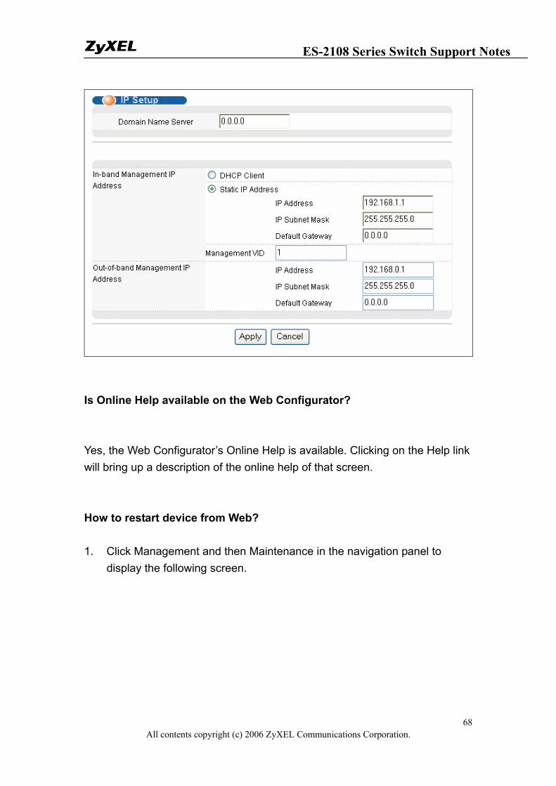
How do I configure an IP address?
From Web Configurator: Click Basic Setting and then IP Setup to display the next screen. *ES-2108 series does NOT have the Out-of-band Management interface.
ES-2108 Series Switch Support Notes
All contents copyright (c) 2006 ZyXEL Communications Corporation. 68
Is Online Help available on the Web Configurator?
Yes, the Web Configurator’s Online Help is available. Clicking on the Help link will bring up a description of the online help of that screen.
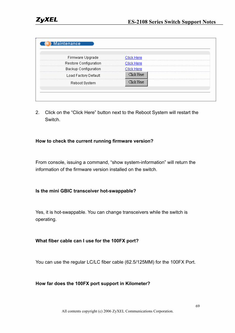
How to restart device from Web?
1. Click Management and then Maintenance in the navigation panel to display the following screen.
ES-2108 Series Switch Support Notes
All contents copyright (c) 2006 ZyXEL Communications Corporation. 69
2. Click on the “Click Here” button next to the Reboot System will restart the
Switch.
How to check the current running firmware version?
From console, issuing a command, “show system-information” will return the information of the firmware version installed on the switch.
Is the mini GBIC transceiver hot-swappable?
Yes, it is hot-swappable. You can change transceivers while the switch is operating.
What fiber cable can I use for the 100FX port?
You can use the regular LC/LC fiber cable (62.5/125MM) for the 100FX Port.
How far does the 100FX port support in Kilometer?
ES-2108 Series Switch Support Notes
All contents copyright (c) 2006 ZyXEL Communications Corporation. 70
The maximum cable length can support up to 2 KM.
Do I need any addition stuff (such like transceiver) when I connect 2
100FX Ports?
No, you do not need another transceiver. However, the LC/LC Fiber is mandatory to connect two 100FX Ports.
Is Port 8 on EC-2108-LC the "Dual-Personality interface" which will share
the interface with the Mini-GB (SFP) or 100FX Port?
No, they are all dedicated ports and none of them are “Dual-Personality interface”. So actually there are 10 dedicated ports on ES-2108-LC.
When I enabled Port Isolated mode, what is the uplink port on
ES-2108-LC?
Both the Mini-GB (SFP) Port and the 100FX Port are the uplink ports when the Switch is in Port Isolated Mode. Each isolated port can communicate with the uplink port(s).