© 1998, stryker corporation - medical equipment | off ... manuals/stryker_tps_5100_manual.pdf · 4...
TRANSCRIPT

1
IMPORTANT INFORMATION: File this in your TPS records
Total Performance System ConsoleREF 5100-1 and 5100-2
Irrigation ConsoleREF 5100-50 and 5100-52
User's Guide••••••••••••••••••••••
Includes setup, safety, repair, and warrantyinformation for the Stryker Total Performance System.
For answers to questions about other equipment, seethe information supplied with that equipment.
TP
S C
onsole 5100-1, 5100-2, 5100-50, and 5100-52
4100 E. MilhamKalamazoo, Michigan 49001 U.S.A.1-800-253-32101-616-323-7700Fax 1-800-999-3811
European Authorized Rep:RA/QA ManagerStrykerBP 50040-95946 Roissy CDGFrancePhone: 33-1-48-17-50-00

2
© 1998, Stryker Corporation
3
Software License NoticeStryker® TPS™ Surgical Tool System products contain software that is installed in the products by Stryker Corporation. StrykerCorporation owns this software; this software is never sold. Each sale of a software containing product is not a sale of such software; itincludes only a license to use the software in the product in which the software was initially installed.
Any license granted by Stryker Corporation to use the software contained in its; products does not give the licensee the right to copy,alter, disassemble, reverse engineer, create derivative works of such software or to use such software in either original or modified form inany product other than the Stryker Corporation product in which the software was initially installed by Stryker Corporation.
ContentsSoftware License Notice..................................................................................... 3
Where to Find Answers ...................................................................................... 4
Warning, Caution, Note Defined ......................................................................... 4
Important Safety Instructions ............................................................................ 5
System Overview ................................................................................................ 6
Operating InstructionsConnecting the EquipmentSymbol Definition................................................................................................ 7
The Control ScreenTPS Start-Up ScreenNo Handpiece Detected ...................................................................................... 8
Functions of the Control ScreenElements of the Control Screen ......................................................................... 9
Select Your System SettingsStandard Features ............................................................................................. 10
Quick Reference Guide (Icon Definition) .......................................................... 11
Handpiece ScreensSaw Handpiece Screen (TPS Oscillating and Sagittal Saws) ........................... 12
Rotary Handpiece Screen (TPS Universal and MicroDrills& TPS MicroDriver) ............................................................................................. 13
Stryker Endoscopy Handpiece Screen(SE5 hand-controlled Endo Shaver, QuadraCut Shaver, QuadraCut Bone Plug,and QuadraCut Small Joint) ................................................................................ 14
Other ScreensMain Option Screen .......................................................................................... 15System Information Screen.............................................................................. 16Handpiece Adjustment Screen ........................................................................ 17Console Adjustment Screen ............................................................................ 18Footswitch Adjustment Screen ....................................................................... 19Footswitch Button Mapping Screen ................................................................ 20Handpiece Button Mapping Screen................................................................. 21Surgeon Preference Screen ............................................................................. 22Messages and Error Messages ........................................................................ 23
Specifications .................................................................................................... 24
Repair/Loaner ProgramLimited Warranty ............................................................................................... 25
Stryker International Subsidiaries ................................................................... 26
4
Where to Find Answers
When you have questions about your Stryker TPS products, there are several places tofind the answers.
In this book
Use this book to set up your system and select console options. This book alsocontains information on system safety, repair, and component warranty.............................................................................................................................................
In TPS component instructions
For answers to questions about any TPS handpiece, attachment, or component , seethe information supplied with that component. A copy of TPS Cleaning, Maintenanceand Sterilization Recommendations is also supplied with each component.............................................................................................................................................
From your Stryker Sales Representative
If you can't find an answer in any of the materials provided or you have questions aboutother Stryker Instruments products, call your Stryker Sales Representative.............................................................................................................................................
From Stryker Customer Service
Please contact our Customer Service Department to order product information litera-ture, a cutting accessories guide, additional TPS maintenance manuals, and componentinstructions by dialing 1-800-253-3210. Outside the U.S.A., contact your nearestStryker subsidiary.............................................................................................................................................
Warning • Caution • Note
This symbol is used to alert the reader to important safety and precautionary information.When displayed on the actual device, it refers the user to accompanying documents.
Please read this manual and follow all instructions carefully. The words WARNING, CAUTION andNOTE carry special meanings and should be carefully reviewed.
WARNING: The personal safety of the patient and/or user may be involved. Disregarding thisinformation could result in injury to the patient and/or O.R. staff.
CAUTION: These instructions point out special service procedures or precautions that must befollowed to avoid damaging the instrument.
NOTE: This provides special information to make maintenance easier or important instructionsmore clear.

5
IMPORTANT SAFETY INSTRUCTIONS
SYSTEM SAFETY■ DO NOT modify ground of power cord.
■ Equipment not suitable for use in the presence offlammable anesthetic mixture with air or with oxygen ornitrous oxide.
■ The Stryker Total Performance System is designed tobe used by persons familiar with surgical procedures.Misuse may cause injury to both patient and systemcomponents. Prior to each use, system componentsshould be inspected for damage. DO NOT use ifdamage is apparent.
■ Use only Stryker TPS components and accessoriesunless otherwise specified.
■ Clean and sterilize handpieces and accessories beforefirst and every use.
■ Use of safety glasses by user and O.R. staff is recom-mended to prevent eye injuries.
HANDPIECE SAFETY■ Read this booklet and the information supplied
with your TPS components. Component instruc-tions provide specific safety information. Refer tothe instructions supplied with Stryker Endoscopyhandpieces when using those handpieces inconjunction with the TPS console.
■ Activate and deactivate handpieces from the sametrigger device. For example, if a handpiece is activatedby the footswitch it must be deactivated from thefootswitch. Exception: In the 1T mode, handpieces canbe deactivated from any device.
■ DO NOT attempt to change a saw, bur, or drill whilehandpiece is running.
■ Stryker handpieces which fail due to long life and/ornose bearing failure may allow foreign matter tomigrate or emit from the distal tip of the handpiece.Fluid may leak into the surgical site, such that mea-sures may be required, per the physician's discretion,to protect the patient from infection.
■ Never rest handpiece on the patient. Improperhandling of a handpiece could result in damage orburns to tissue.
■ Do not place a footswitch-controlled TPS handpiecenear or on a magnetic pad or tray. The magnetic fieldcan simulate a Universal Handswitch and may causethe handpieces to run inadvertently.
■ DO NOT modify any bur to fit the handpieces. Use
only Stryker approved burs. Other burs may not fitproperly in the handpiece. During use they may comeout of the handpiece or bend which would result indamage to tissue in the surgical site due to loss ofcontrol of the bur.
■ Burs and blades are intended for single use only.
■ Excessive pressure, such as bending or prying, maycause accessory to bend or break and cause tissuedamage to patient and/or O.R. staff.
■ Heavy sideloads and/or long operating periodsoccasionally will cause overheating of the distal tip andthe body of handpieces to the point where the hand-piece is uncomfortable to hold or causes injury to thepatient.
■ If the recommended duty cycle is not followed, thehandpiece may overheat and cause injury to patientand/or operating room staff. See the Duty Cycleinformation supplied with each handpiece.
■ Excessive pressure, such as bending and/or pryingwith a bur, may cause the bur to bend or fracture. Ifoperated at a high speed, it is possible that the bur willbend yet further. This could result in damage to tissuein the surgical site, handpiece vibration that causes losttactile control, or breakage of the bur such that thebroken piece would be ejected at a high velocityendangering the patient and/or O.R. staff. It is there-fore recommended that safety glasses be used.
■ Excessive pressure, such as bending and prying withblade, may cause the blade to bend or fracture andcould result in damage to tissue in the surgical siteand/or loss of tactile control.
■ If using a device with a safety lock, such as aMicroDriver or Universal Handswitch, always place thatdevice in the SAFE position when not in use. IMPOR-TANT: Be aware that the TPS footswitch will overridethe Universal Handswitch SAFE setting.
■ DO NOT use a bur or blade without the appropriateguard or attachment as user and/or patient injury mayresult.
■ Please note the handpiece starts with rapid accelera-tion when the footswitch or handswitch is activated.
■ During initial use of your TPS handpieces, monitor theheat response in relation to the type of surgicalprocedure being performed. Frequently check thedistal tip and body until you are familiar with itstemperature rise characteristics. Failure to pay closeattention to handpiece temperature may cause burninjury to patient.
WARNING: The personal safety of the patient and/or user may be involved. Disregarding this informationcould result in injury to the patient and/or O.R. staff. Read and understand the following warnings.
6
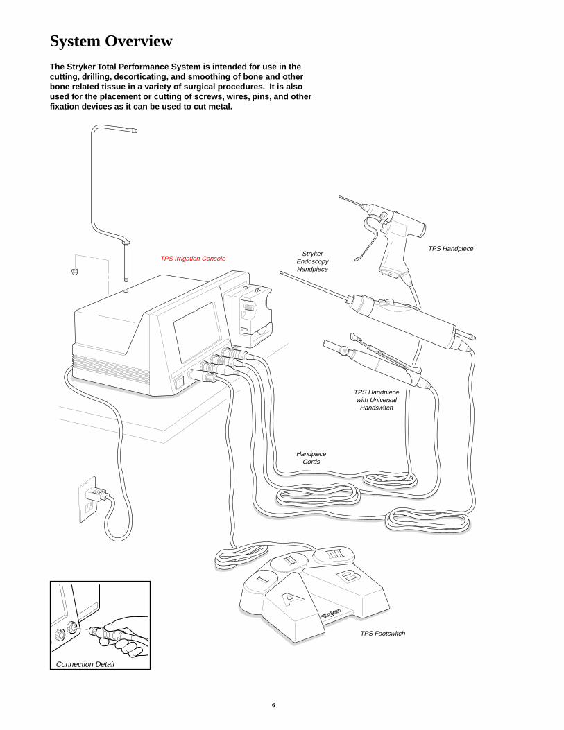
Connection Detail
System OverviewThe Stryker Total Performance System is intended for use in thecutting, drilling, decorticating, and smoothing of bone and otherbone related tissue in a variety of surgical procedures. It is alsoused for the placement or cutting of screws, wires, pins, and otherfixation devices as it can be used to cut metal.
TPS Footswitch
TPS Handpiece
TPS Irrigation ConsoleStryker
EndoscopyHandpiece
TPS Handpiecewith UniversalHandswitch
HandpieceCords
7
Operating Instructions
The TPS Console powers multiple handpieces while allowing the user to program a number of customizedsettings.
WARNING: Before using this system, read and understand the information in this manual and theinstructions supplied with each TPS component and Stryker Endoscopy handpieces. Pay closeattention to the User/Patient Safety Information .
WARNING: Familiarization with the Total Performance System prior to use is important. If you haveany questions, contact your Stryker Instruments representative or Stryker Customer Service at 1-800-253-3210.
WARNING: Prior to use, system components should be operated and inspected for any damage. DO NOT useif damage is apparent.
Connecting the Equipment
This is a system overview. For specific instructions on each TPScomponent, refer to the information supplied with the component.
1. Place your console on a sturdy, flat surface near a hospital grade outlet.
2. Plug the console's power cord into the recessed power socket on the back ofthe console.
3. Plug the other end of the power cord into a hospital-grade wall outlet.
4. Turn on the console. The on/off switch is located on the front of the console.
NOTE: As you set up the system, the console's screen will change to indicate thevarious components as they are plugged in.
5. If using a Footswitch, plug the footswitch cable into the console port markedFOOTSWITCH. Align orientation marks and gently push connectors together.
CAUTION: All TPS Cords have push/pull connectors. Do not thread or twistfor insertion or removal.
6. Plug the handpiece cord(s) into the console port(s) marked HANDPIECE. Alignconnector orientation marks and gently push connectors together.NOTE: Ports marked TPS 1 and TPS 2 are for Stryker TPS handpieces only.The port marked ENDO is intended for the following list of Stryker Endoscopyhandpieces: SE5 Hand-controlled, (272-704); QuadraCut Shaver (275-701);QuadraCut Bone Plug (275-705); and QuadraCut small Joint (275-601).
NOTE: If using a TPS Universal Handswitch, attach it to the handpiece before youplug the cord into the handpiece.
7. Plug the other end of the handpiece cord(s) into the handpiece(s).
8. Attach cutting accessories to handpieces. Instructions supplied with eachhandpiece or attachment provide details for cutting accessory assembly.
WARNING: Use only Stryker approved cutting accessories.
9. If using an Irrigation Console (REF 5100-50 or 5100-52), assemble IrrigationPole (REF 5100-50-28) to the console as shown. Hang irrigation bag from pole.Install irrigation cassette into the pump. Attach irrigation clips to handpieces andconnect tubing.
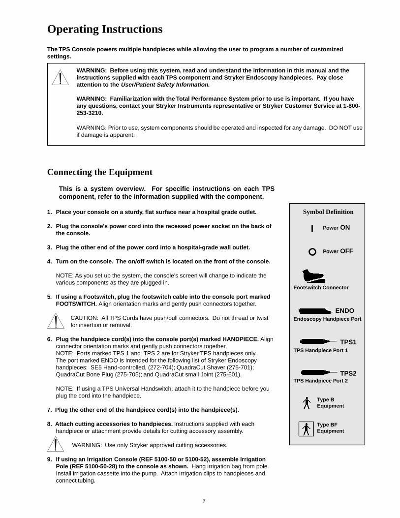
Symbol Definition
Power ON
Power OFF
Footswitch Connector
ENDOEndoscopy Handpiece Port
TPS1TPS Handpiece Port 1
TPS2TPS Handpiece Port 2
Type BEquipment
Type BFEquipment
8
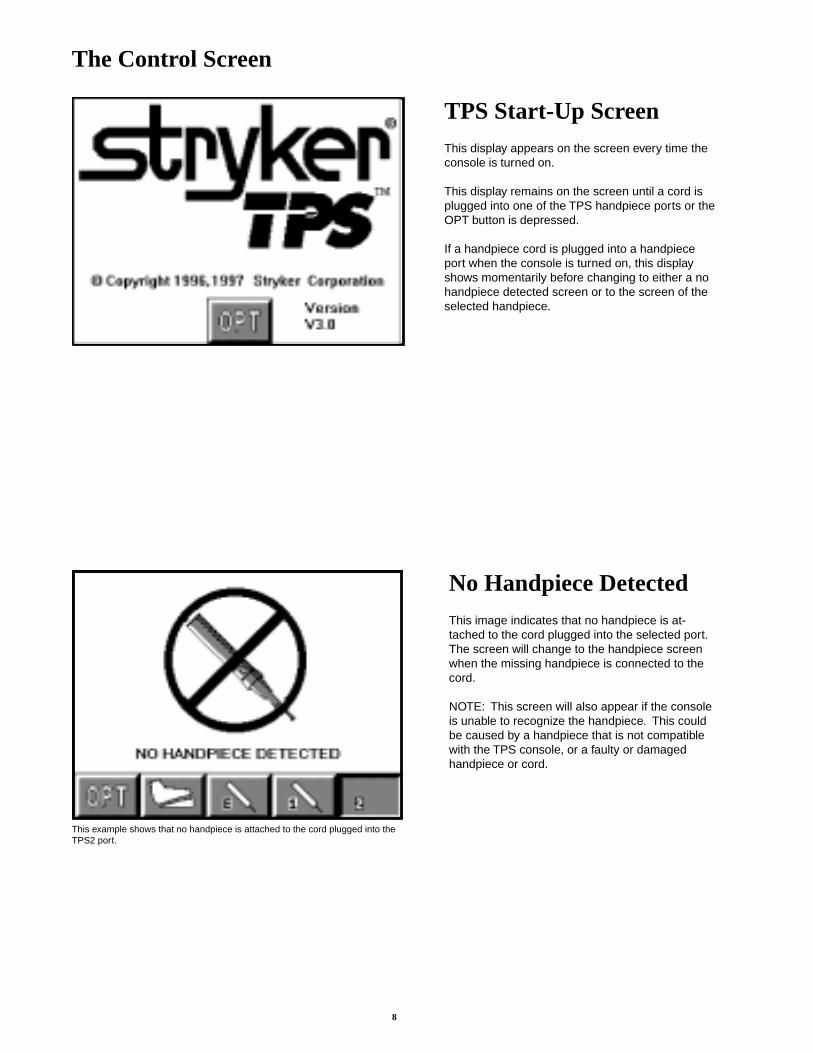
The Control Screen
No Handpiece DetectedThis image indicates that no handpiece is at-tached to the cord plugged into the selected port.The screen will change to the handpiece screenwhen the missing handpiece is connected to thecord.
NOTE: This screen will also appear if the consoleis unable to recognize the handpiece. This couldbe caused by a handpiece that is not compatiblewith the TPS console, or a faulty or damagedhandpiece or cord.
This example shows that no handpiece is attached to the cord plugged into theTPS2 port.
TPS Start-Up ScreenThis display appears on the screen every time theconsole is turned on.
This display remains on the screen until a cord isplugged into one of the TPS handpiece ports or theOPT button is depressed.
If a handpiece cord is plugged into a handpieceport when the console is turned on, this displayshows momentarily before changing to either a nohandpiece detected screen or to the screen of theselected handpiece.
9
Functions of the Control Screen
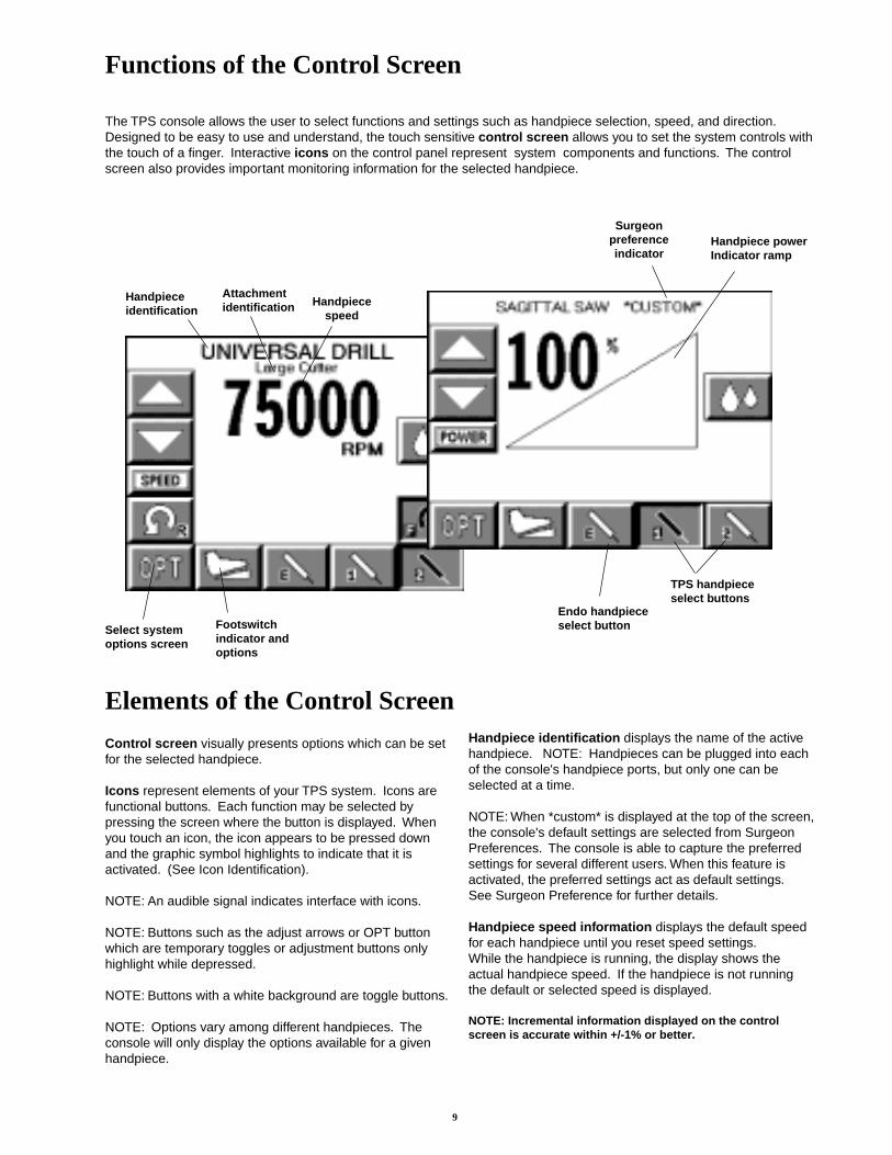
The TPS console allows the user to select functions and settings such as handpiece selection, speed, and direction.Designed to be easy to use and understand, the touch sensitive control screen allows you to set the system controls withthe touch of a finger. Interactive icons on the control panel represent system components and functions. The controlscreen also provides important monitoring information for the selected handpiece.
Select systemoptions screen
Footswitchindicator andoptions
Handpieceidentification
Handpiecespeed
TPS handpieceselect buttons
Endo handpieceselect button
Elements of the Control Screen
Attachmentidentification
Handpiece powerIndicator ramp
Surgeonpreferenceindicator
Control screen visually presents options which can be setfor the selected handpiece.
Icons represent elements of your TPS system. Icons arefunctional buttons. Each function may be selected bypressing the screen where the button is displayed. Whenyou touch an icon, the icon appears to be pressed downand the graphic symbol highlights to indicate that it isactivated. (See Icon Identification).
NOTE: An audible signal indicates interface with icons.
NOTE: Buttons such as the adjust arrows or OPT buttonwhich are temporary toggles or adjustment buttons onlyhighlight while depressed.
NOTE: Buttons with a white background are toggle buttons.
NOTE: Options vary among different handpieces. Theconsole will only display the options available for a givenhandpiece.
Handpiece identification displays the name of the activehandpiece. NOTE: Handpieces can be plugged into eachof the console's handpiece ports, but only one can beselected at a time.
NOTE: When *custom* is displayed at the top of the screen,the console's default settings are selected from SurgeonPreferences. The console is able to capture the preferredsettings for several different users. When this feature isactivated, the preferred settings act as default settings.See Surgeon Preference for further details.
Handpiece speed information displays the default speedfor each handpiece until you reset speed settings.While the handpiece is running, the display shows theactual handpiece speed. If the handpiece is not runningthe default or selected speed is displayed.
NOTE: Incremental information displayed on the controlscreen is accurate within +/-1% or better.
10
Select Your System SettingsNOTE: When the console is turned on, its defaultsetting is factory default unless a Surgeon Preferencesetting is selected as the start up default. See SurgeonPreference for further details.
1. Handpiece select buttons enable you to activate thehandpiece plugged into one of the three ports on thefront of the console. To display the control screen forthe handpiece plugged into the TPS 1 port, touchthe corresponding handpiece select icon. The iconhighlights and appears pressed down.
NOTE: Selecting a handpiece icon activates thecorresponding handpiece and displays its specificcontrol screen.
2. Change the maximum handpiece speed. Press theadjustment arrows to change the handpiece speedsetting incrementally until the desired speed is reached.
• Saws - The set point is displayed as a percentage ofmaximum power and vertical line on the speed ramp.During handpiece operation, the percentage readingand speed ramp displays the power level.
• Rotary handpieces - The speed set point is displayed.During handpiece operation, the current speed isdisplayed.
3. Select various settings as desired. Refer to thecontrol screens on the following pages for details foreach handpiece.
4. Select the OPT icon to access the MAIN OPTIONscreen. This screen allows access to general consoleand user settings as well as direct access to eachhandpiece option screen.
NOTE: Alternatively, the screen returns to the activehandpiece control screen when the handpiece isactivated or the handpiece name is touched.
5. Touch the EXIT icon to return to the active hand-piece control screen.
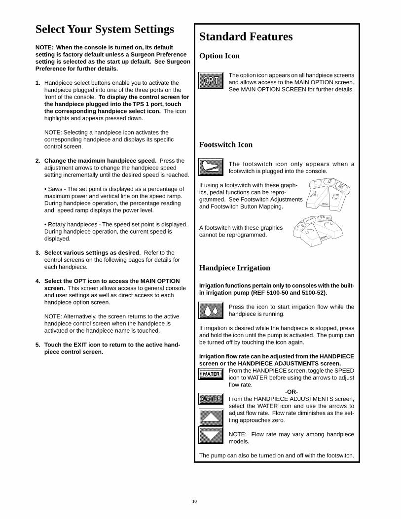
Handpiece Irrigation
Irrigation functions pertain only to consoles with the built-in irrigation pump (REF 5100-50 and 5100-52).
Press the icon to start irrigation flow while thehandpiece is running.
If irrigation is desired while the handpiece is stopped, pressand hold the icon until the pump is activated. The pump canbe turned off by touching the icon again.
Irrigation flow rate can be adjusted from the HANDPIECEscreen or the HANDPIECE ADJUSTMENTS screen.
From the HANDPIECE screen, toggle the SPEEDicon to WATER before using the arrows to adjustflow rate.
-OR-From the HANDPIECE ADJUSTMENTS screen,select the WATER icon and use the arrows toadjust flow rate. Flow rate diminishes as the set-ting approaches zero.
NOTE: Flow rate may vary among handpiecemodels.
The pump can also be turned on and off with the footswitch.
Option Icon
The option icon appears on all handpiece screensand allows access to the MAIN OPTION screen.See MAIN OPTION SCREEN for further details.
Footswitch Icon
The footswitch icon only appears when afootswitch is plugged into the console.
If using a footswitch with these graph-ics, pedal functions can be repro-grammed. See Footswitch Adjustmentsand Footswitch Button Mapping.
A footswitch with these graphicscannot be reprogrammed.
Standard Features
11
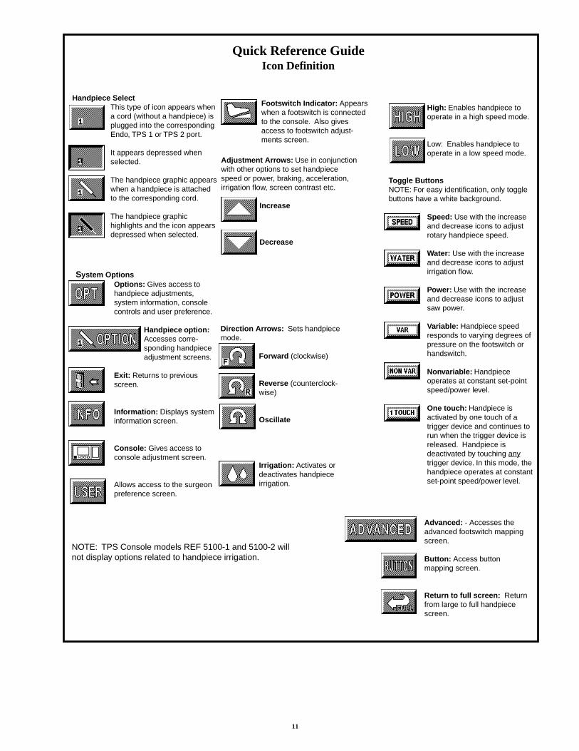
System OptionsOptions: Gives access tohandpiece adjustments,system information, consolecontrols and user preference.
Handpiece option:Accesses corre-sponding handpieceadjustment screens.
Exit: Returns to previousscreen.
Information: Displays systeminformation screen.
Console: Gives access toconsole adjustment screen.
Allows access to the surgeonpreference screen.
Handpiece SelectThis type of icon appears whena cord (without a handpiece) isplugged into the correspondingEndo, TPS 1 or TPS 2 port.
It appears depressed whenselected.
The handpiece graphic appearswhen a handpiece is attachedto the corresponding cord.
The handpiece graphichighlights and the icon appearsdepressed when selected.
High: Enables handpiece tooperate in a high speed mode.
Low: Enables handpiece tooperate in a low speed mode.
Toggle ButtonsNOTE: For easy identification, only togglebuttons have a white background.
Speed: Use with the increaseand decrease icons to adjustrotary handpiece speed.
Water: Use with the increaseand decrease icons to adjustirrigation flow.
Power: Use with the increaseand decrease icons to adjustsaw power.
Variable: Handpiece speedresponds to varying degrees ofpressure on the footswitch orhandswitch.
Nonvariable: Handpieceoperates at constant set-pointspeed/power level.
One touch: Handpiece isactivated by one touch of atrigger device and continues torun when the trigger device isreleased. Handpiece isdeactivated by touching anytrigger device. In this mode, thehandpiece operates at constantset-point speed/power level.
Footswitch Indicator: Appearswhen a footswitch is connectedto the console. Also givesaccess to footswitch adjust-ments screen.
Quick Reference GuideIcon Definition
Direction Arrows: Sets handpiecemode.
Forward (clockwise)
Reverse (counterclock-wise)
Oscillate
Irrigation: Activates ordeactivates handpieceirrigation.
Adjustment Arrows: Use in conjunctionwith other options to set handpiecespeed or power, braking, acceleration,irrigation flow, screen contrast etc.
Increase
Decrease
Advanced: - Accesses theadvanced footswitch mappingscreen.
Button: Access buttonmapping screen.
Return to full screen: Returnfrom large to full handpiecescreen.
NOTE: TPS Console models REF 5100-1 and 5100-2 willnot display options related to handpiece irrigation.
12
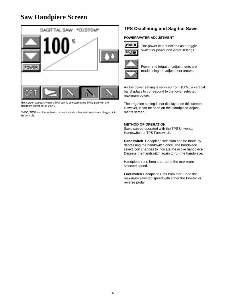
Saw Handpiece Screen
TPS Oscillating and Sagittal Saws
POWER/WATER ADJUSTMENT
The power icon functions as a toggleswitch for power and water settings.
Power and irrigation adjustments aremade using the adjustment arrows.
As the power setting is reduced from 100%, a verticalbar displays to correspond to the lower selectedmaximum power.
The irrigation setting is not displayed on this screen.However, it can be seen on the Handpiece Adjust-ments screen.
METHOD OF OPERATIONSaws can be operated with the TPS UniversalHandswitch or TPS Footswitch.
Handswitch Handpiece selection can be made bydepressing the handswitch once. The handpieceselect icon changes to indicate the active handpiece.Depress the handswitch again to run the handpiece.
Handpiece runs from start-up to the maximumselected speed.
Footswitch Handpiece runs from start-up to themaximum selected speed with either the forward orreverse pedal.
This screen appears when a TPS saw is selected at the TPS1 port with themaximum power set at 100%.
ENDO, TPS2 and the footswitch icons indicate other instruments are plugged intothe console.
13
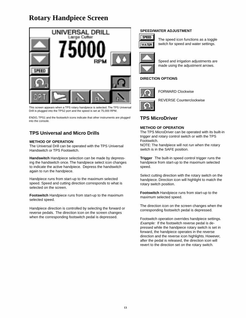
Rotary Handpiece Screen
This screen appears when a TPS rotary handpiece is selected. The TPS UniversalDrill is plugged into the TPS2 port and the speed is set at 75,000 RPM.
ENDO, TPS1 and the footswitch icons indicate that other instruments are pluggedinto the console.
SPEED/WATER ADJUSTMENT
The speed icon functions as a toggleswitch for speed and water settings.
Speed and irrigation adjustments aremade using the adjustment arrows.
DIRECTION OPTIONS
FORWARD Clockwise
REVERSE Counterclockwise
TPS MicroDriver
METHOD OF OPERATIONThe TPS MicroDriver can be operated with its built-intrigger and rotary control switch or with the TPSFootswitch.NOTE: The handpiece will not run when the rotaryswitch is in the SAFE position.
Trigger The built-in speed control trigger runs thehandpiece from start-up to the maximum selectedspeed.
Select cutting direction with the rotary switch on thehandpiece. Direction icon will highlight to match therotary switch position.
Footswitch Handpiece runs from start-up to themaximum selected speed.
The direction icon on the screen changes when thecorresponding footswitch pedal is depressed.
Footswitch operation overrides handpiece settings.Example: If the footswitch reverse pedal is de-pressed while the handpiece rotary switch is set inforward, the handpiece operates in the reversedirection and the reverse icon highlights. However,after the pedal is released, the direction icon willrevert to the direction set on the rotary switch.
TPS Universal and Micro Drills
METHOD OF OPERATIONThe Universal Drill can be operated with the TPS UniversalHandswitch or TPS Footswitch.
Handswitch Handpiece selection can be made by depress-ing the handswitch once. The handpiece select icon changesto indicate the active handpiece. Depress the handswitchagain to run the handpiece.
Handpiece runs from start-up to the maximum selectedspeed. Speed and cutting direction corresponds to what isselected on the screen.
Footswitch Handpiece runs from start-up to the maximumselected speed.
Handpiece direction is controlled by selecting the forward orreverse pedals. The direction icon on the screen changeswhen the corresponding footswitch pedal is depressed.
14
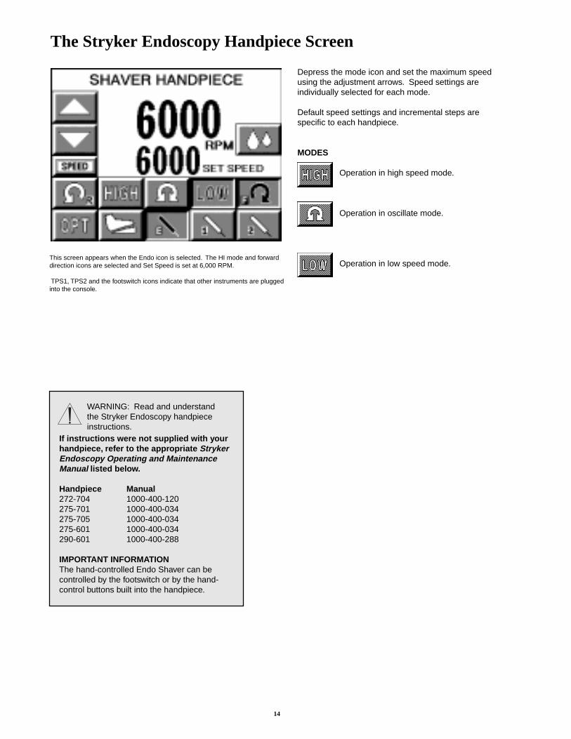
Depress the mode icon and set the maximum speedusing the adjustment arrows. Speed settings areindividually selected for each mode.
Default speed settings and incremental steps arespecific to each handpiece.
MODES
Operation in high speed mode.
Operation in oscillate mode.
Operation in low speed mode.
The Stryker Endoscopy Handpiece Screen
This screen appears when the Endo icon is selected. The HI mode and forwarddirection icons are selected and Set Speed is set at 6,000 RPM.
TPS1, TPS2 and the footswitch icons indicate that other instruments are pluggedinto the console.
WARNING: Read and understandthe Stryker Endoscopy handpieceinstructions.
If instructions were not supplied with yourhandpiece, refer to the appropriate StrykerEndoscopy Operating and MaintenanceManual listed below.
Handpiece Manual272-704 1000-400-120275-701 1000-400-034275-705 1000-400-034275-601 1000-400-034290-601 1000-400-288
IMPORTANT INFORMATIONThe hand-controlled Endo Shaver can becontrolled by the footswitch or by the hand-control buttons built into the handpiece.
15
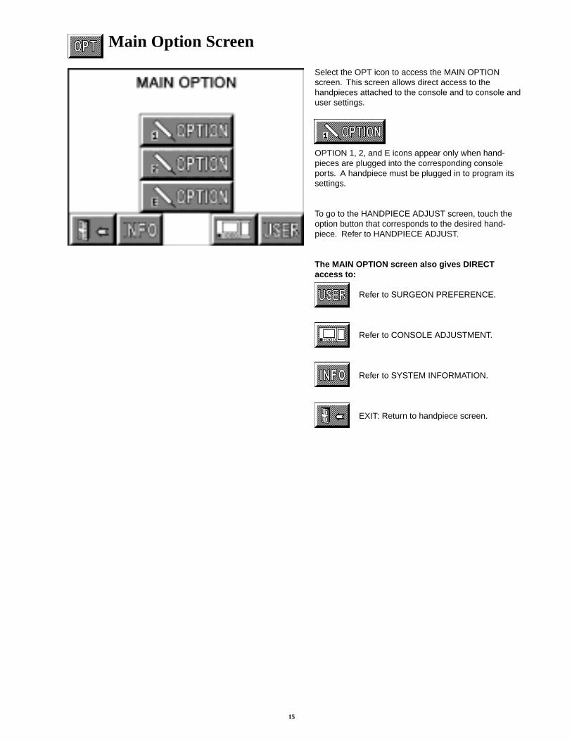
Main Option Screen
Select the OPT icon to access the MAIN OPTIONscreen. This screen allows direct access to thehandpieces attached to the console and to console anduser settings.
OPTION 1, 2, and E icons appear only when hand-pieces are plugged into the corresponding consoleports. A handpiece must be plugged in to program itssettings.
To go to the HANDPIECE ADJUST screen, touch theoption button that corresponds to the desired hand-piece. Refer to HANDPIECE ADJUST.
The MAIN OPTION screen also gives DIRECTaccess to:
Refer to SURGEON PREFERENCE.
Refer to CONSOLE ADJUSTMENT.
Refer to SYSTEM INFORMATION.
EXIT: Return to handpiece screen.
16
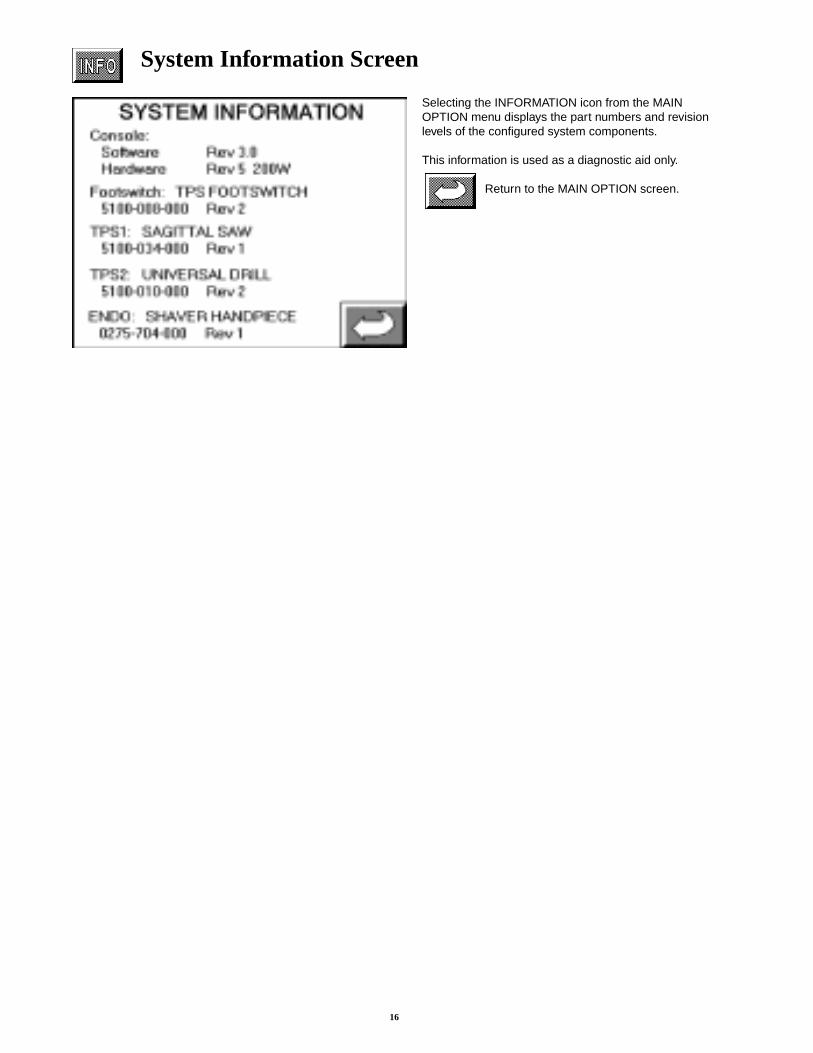
System Information Screen
Selecting the INFORMATION icon from the MAINOPTION menu displays the part numbers and revisionlevels of the configured system components.
This information is used as a diagnostic aid only.
Return to the MAIN OPTION screen.
17
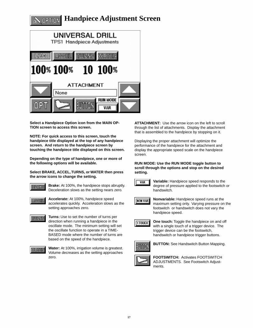
Handpiece Adjustment Screen
Select a Handpiece Option icon from the MAIN OP-TION screen to access this screen.
NOTE: For quick access to this screen, touch thehandpiece title displayed at the top of any handpiecescreen. And return to the handpiece screen bytouching the handpiece title displayed on this screen.
Depending on the type of handpiece, one or more ofthe following options will be available.
Select BRAKE, ACCEL, TURNS, or WATER then pressthe arrow icons to change the setting.
Brake: At 100%, the handpiece stops abruptly.Deceleration slows as the setting nears zero.
Accelerate: At 100%, handpiece speedaccelerates quickly. Acceleration slows as thesetting approaches zero.
Turns: Use to set the number of turns perdirection when running a handpiece in theoscillate mode. The minimum setting will setthe oscillate function to operate in a TIME-BASED mode where the number of turns arebased on the speed of the handpiece.
Water: At 100%, irrigation volume is greatest.Volume decreases as the setting approacheszero.
ATTACHMENT: Use the arrow icon on the left to scrollthrough the list of attachments. Display the attachmentthat is assembled to the handpiece by stopping on it.
Displaying the proper attachment will optimize theperformance of the handpiece for the attachment anddisplay the appropriate speed scale on the handpiecescreen.
RUN MODE: Use the RUN MODE toggle button toscroll through the options and stop on the desiredsetting.
Variable: Handpiece speed responds to thedegree of pressure applied to the footswitch orhandswitch.
Nonvariable: Handpiece speed runs at themaximum setting only. Varying pressure on thefootswitch or handswitch does not vary thehandpiece speed.
One touch: Toggle the handpiece on and offwith a single touch of a trigger device. Thetrigger device can be the footswitch,handswitch or handpiece trigger buttons.
BUTTON: See Handswitch Button Mapping.
FOOTSWITCH: Activates FOOTSWITCHADJUSTMENTS. See Footswitch Adjust-ments.

18
Console Adjustment Screen
Select the CONSOLE ADJUSTMENTS icon from theMAIN OPTION screen to access this screen.
Select CONTRAST, BRIGHTNESS or VOLUME thenpress the arrow icons to change the setting.
Contrast : Screen contrast lightens athigher settings. The chosen settingremains until reset.
Brightness: Screen brightnessintensifies at higher settings.
Volume: The audible signal is louder athigher settings.
Use the BIG SCREEN toggle button to select one ofthe following options.
Automatic: A big screen is displayed whilethe handpiece is running and automaticallyreturns to the full screen when handpiecestops.
On: The big screen is continuously dis-played. It can be temporarily switched backto the full screen by touching the Full Screenicon which appears in the lower right cornerof each handpiece screen. See example ofscreens below.
Off: The big screen option is turned off.Only a full screen is displayed.
Example of big screen.Example of full screen.
19
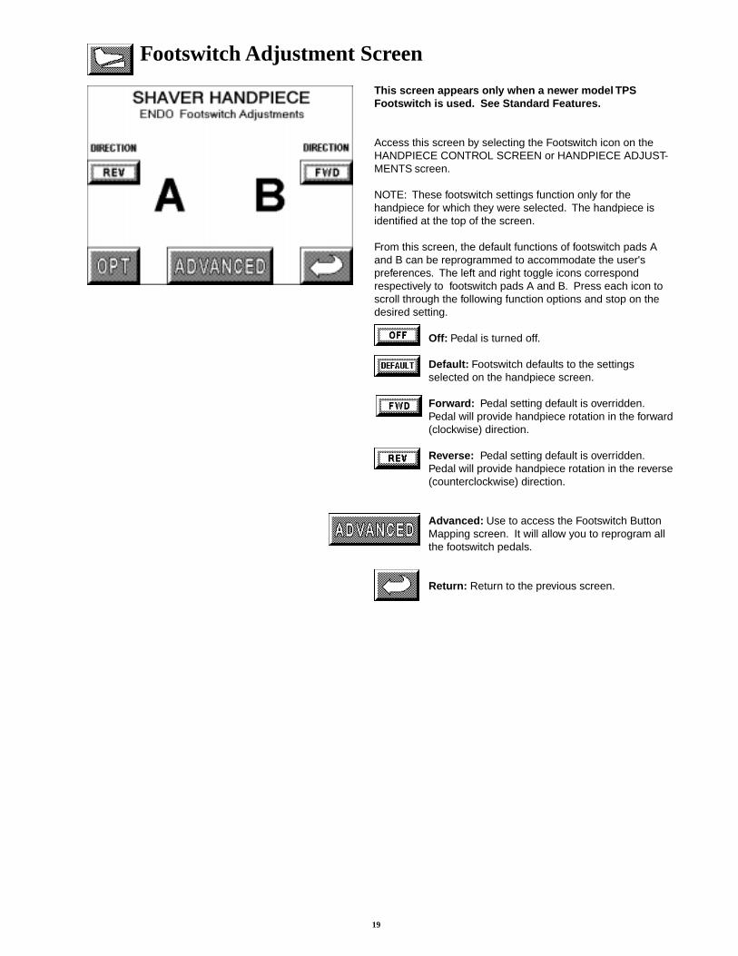
This screen appears only when a newer model TPSFootswitch is used. See Standard Features.
Access this screen by selecting the Footswitch icon on theHANDPIECE CONTROL SCREEN or HANDPIECE ADJUST-MENTS screen.
NOTE: These footswitch settings function only for thehandpiece for which they were selected. The handpiece isidentified at the top of the screen.
From this screen, the default functions of footswitch pads Aand B can be reprogrammed to accommodate the user'spreferences. The left and right toggle icons correspondrespectively to footswitch pads A and B. Press each icon toscroll through the following function options and stop on thedesired setting.
Off: Pedal is turned off.
Default: Footswitch defaults to the settingsselected on the handpiece screen.
Forward: Pedal setting default is overridden.Pedal will provide handpiece rotation in the forward(clockwise) direction.
Reverse: Pedal setting default is overridden.Pedal will provide handpiece rotation in the reverse(counterclockwise) direction.
Advanced: Use to access the Footswitch ButtonMapping screen. It will allow you to reprogram allthe footswitch pedals.
Return: Return to the previous screen.
Footswitch Adjustment Screen
20
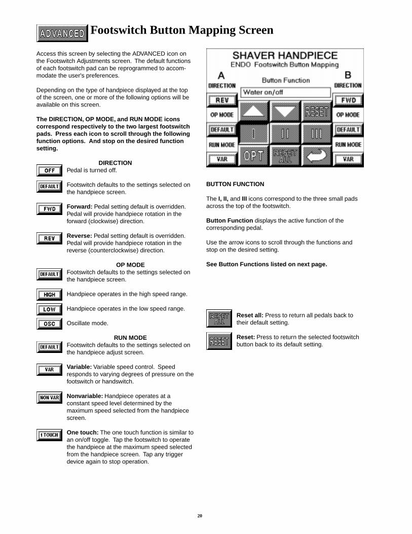
Footswitch Button Mapping Screen
Access this screen by selecting the ADVANCED icon onthe Footswitch Adjustments screen. The default functionsof each footswitch pad can be reprogrammed to accom-modate the user's preferences.
Depending on the type of handpiece displayed at the topof the screen, one or more of the following options will beavailable on this screen.
The DIRECTION, OP MODE, and RUN MODE iconscorrespond respectively to the two largest footswitchpads. Press each icon to scroll through the followingfunction options. And stop on the desired functionsetting.
DIRECTIONPedal is turned off.
Footswitch defaults to the settings selected onthe handpiece screen.
Forward: Pedal setting default is overridden.Pedal will provide handpiece rotation in theforward (clockwise) direction.
Reverse: Pedal setting default is overridden.Pedal will provide handpiece rotation in thereverse (counterclockwise) direction.
OP MODEFootswitch defaults to the settings selected onthe handpiece screen.
Handpiece operates in the high speed range.
Handpiece operates in the low speed range.
Oscillate mode.
RUN MODEFootswitch defaults to the settings selected onthe handpiece adjust screen.
Variable: Variable speed control. Speedresponds to varying degrees of pressure on thefootswitch or handswitch.
Nonvariable: Handpiece operates at aconstant speed level determined by themaximum speed selected from the handpiecescreen.
One touch: The one touch function is similar toan on/off toggle. Tap the footswitch to operatethe handpiece at the maximum speed selectedfrom the handpiece screen. Tap any triggerdevice again to stop operation.
BUTTON FUNCTION
The I, II, and III icons correspond to the three small padsacross the top of the footswitch.
Button Function displays the active function of thecorresponding pedal.
Use the arrow icons to scroll through the functions andstop on the desired setting.
See Button Functions listed on next page.
Reset all: Press to return all pedals back totheir default setting.
Reset: Press to return the selected footswitchbutton back to its default setting.
21
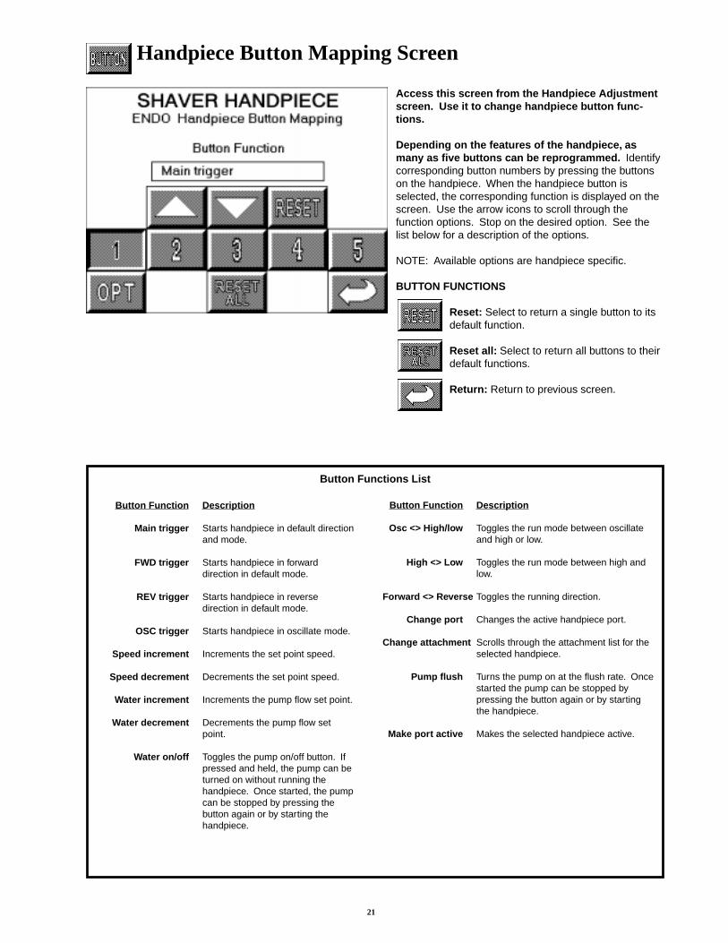
Handpiece Button Mapping Screen
Access this screen from the Handpiece Adjustmentscreen. Use it to change handpiece button func-tions.
Depending on the features of the handpiece, asmany as five buttons can be reprogrammed. Identifycorresponding button numbers by pressing the buttonson the handpiece. When the handpiece button isselected, the corresponding function is displayed on thescreen. Use the arrow icons to scroll through thefunction options. Stop on the desired option. See thelist below for a description of the options.
NOTE: Available options are handpiece specific.
BUTTON FUNCTIONS
Reset: Select to return a single button to itsdefault function.
Reset all: Select to return all buttons to theirdefault functions.
Return: Return to previous screen.
Button Function Description
Main trigger Starts handpiece in default directionand mode.
FWD trigger Starts handpiece in forwarddirection in default mode.
REV trigger Starts handpiece in reversedirection in default mode.
OSC trigger Starts handpiece in oscillate mode.
Speed increment Increments the set point speed.
Speed decrement Decrements the set point speed.
Water increment Increments the pump flow set point.
Water decrement Decrements the pump flow setpoint.
Water on/off Toggles the pump on/off button. Ifpressed and held, the pump can beturned on without running thehandpiece. Once started, the pumpcan be stopped by pressing thebutton again or by starting thehandpiece.
Button Function Description
Osc <> High/low Toggles the run mode between oscillateand high or low.
High <> Low Toggles the run mode between high andlow.
Forward <> Reverse Toggles the running direction.
Change port Changes the active handpiece port.
Change attachment Scrolls through the attachment list for theselected handpiece.
Pump flush Turns the pump on at the flush rate. Oncestarted the pump can be stopped bypressing the button again or by startingthe handpiece.
Make port active Makes the selected handpiece active.
Button Functions List
22
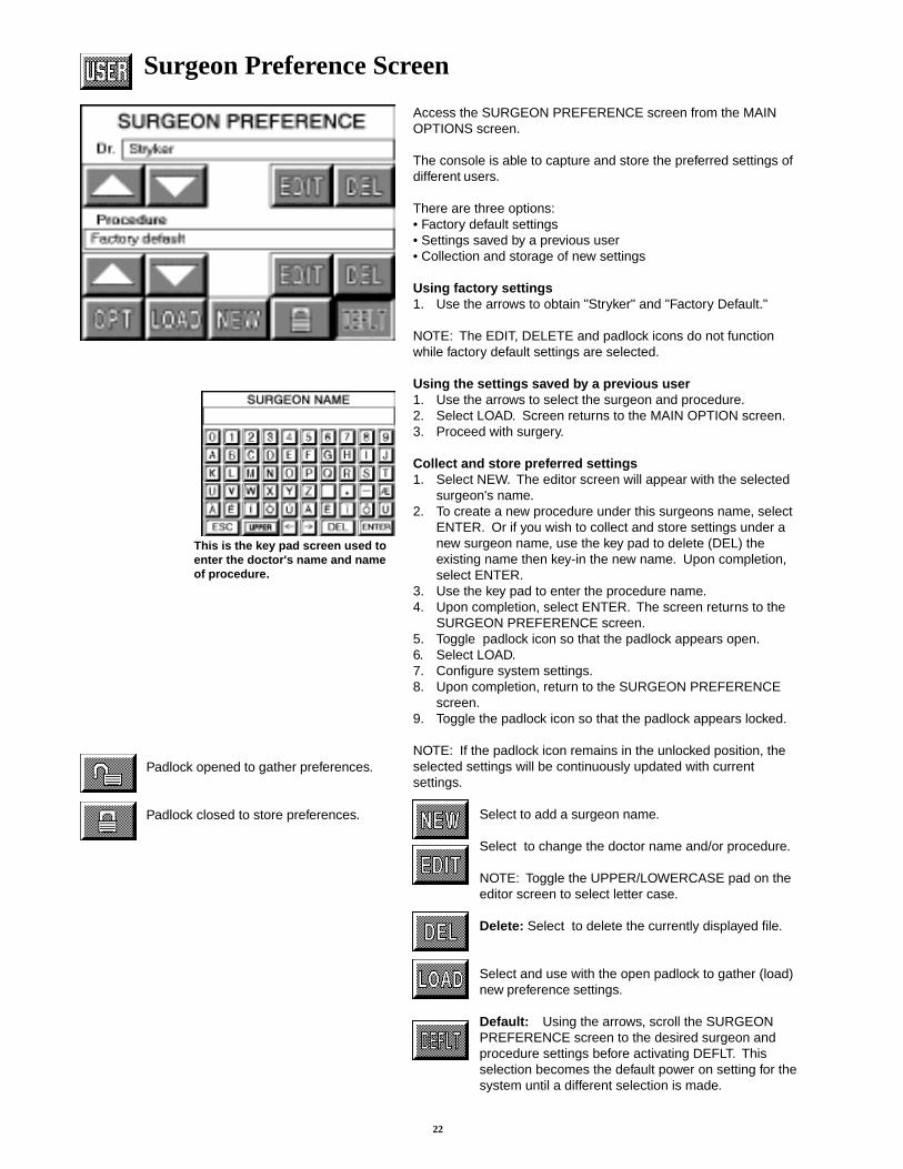
Surgeon Preference Screen
Access the SURGEON PREFERENCE screen from the MAINOPTIONS screen.
The console is able to capture and store the preferred settings ofdifferent users.
There are three options:• Factory default settings• Settings saved by a previous user• Collection and storage of new settings
Using factory settings1. Use the arrows to obtain "Stryker" and "Factory Default."
NOTE: The EDIT, DELETE and padlock icons do not functionwhile factory default settings are selected.
Using the settings saved by a previous user1. Use the arrows to select the surgeon and procedure.2. Select LOAD. Screen returns to the MAIN OPTION screen.3. Proceed with surgery.
Collect and store preferred settings1. Select NEW. The editor screen will appear with the selected
surgeon's name.2. To create a new procedure under this surgeons name, select
ENTER. Or if you wish to collect and store settings under anew surgeon name, use the key pad to delete (DEL) theexisting name then key-in the new name. Upon completion,select ENTER.
3. Use the key pad to enter the procedure name.4. Upon completion, select ENTER. The screen returns to the
SURGEON PREFERENCE screen.5. Toggle padlock icon so that the padlock appears open.6. Select LOAD.7. Configure system settings.8. Upon completion, return to the SURGEON PREFERENCE
screen.9. Toggle the padlock icon so that the padlock appears locked.
NOTE: If the padlock icon remains in the unlocked position, theselected settings will be continuously updated with currentsettings.
Select to add a surgeon name.
Select to change the doctor name and/or procedure.
NOTE: Toggle the UPPER/LOWERCASE pad on theeditor screen to select letter case.
Delete: Select to delete the currently displayed file.
Select and use with the open padlock to gather (load)new preference settings.
Default: Using the arrows, scroll the SURGEONPREFERENCE screen to the desired surgeon andprocedure settings before activating DEFLT. Thisselection becomes the default power on setting for thesystem until a different selection is made.
This is the key pad screen used toenter the doctor's name and nameof procedure.
Padlock opened to gather preferences.
Padlock closed to store preferences.
23
MessagesMessage If you select OK to this question:
Delete all the surgeon's procedures? The surgeon ID and all procedures will be deleted.
Change the name of all the surgeon's Procedures listed under the surgeon will be moved underprocedures? the current surgeon's name.
Identical record found.
Maximum number of records exceeded. Please delete inactive records.
Initializing console hardware. Please wait.
Handpiece has reached recommended service interval. Please return for service at earliest convenience.
Handpiece does not support the selected preference. Default handpiece setting will be used.
Handpiece temperature has exceeded its nominal operating range and may cause burning.
Handpiece temperature has exceeded its operating range. Allow to cool before restarting.
Procedure name unspecified.
Ensure handpiece speed does not exceed specified attachment limitations. Failure to do so may result in user and/or patientinjury.
Error MessagesMessage Action to TakeError 001. Console hardware fault detected. Return console to Stryker for repair.
Error 002. Console hardware fault detected. Turn unit off and on again. If problem persists, returnContact your Stryker service representative. console to Stryker for repair.
Error 003. Console hardware fault detected. Turn unit off and on again. If problem persists, returnContact your Stryker service representative. console to Stryker for repair.
Error 004. Footswitch fault detected, right pedal will be disabled. Unplug Footswitch from console and plug in again.Contact your Stryker service representative. If problem persists, return footswtich to Stryker for repair.
Error 005. Footswitch fault detected, left pedal will be disabled. Unplug Footswitch from console and plug in again.Contact your Stryker service representative. If problem persists return footswtich to Stryker for repair.
Error 006. Footswitch unreadable. Unplug Footswitch from console andContact your Stryker service representative. plug in again. If problem persists,
return footswitch to Stryker for repair.
Error 007. Handpiece fault detected, handpiece triggers will be Unplug cord from handpiece and plug in again.disabled. Contact your Stryker service representative. If problem persists, return handpiece to Stryker for repair.
Error 008. Handpiece unreadable. Unplug handpiece from console and plug in again.Contact your Stryker service representative. If problem persists, return handpiece Stryker for repair.
Error 009. Handpiece requires additional console hardware. Call your Stryker Instruments sales representative.Contact your Stryker service representative.
Error 010 Handpiece requires additional console hardware. Call your Stryker Instruments sales representative.Contact your Stryker service representative.
Error 011 Handpiece requires additional console hardware. Call your Stryker Instruments sales representative.Contact your Stryker service representative.
24
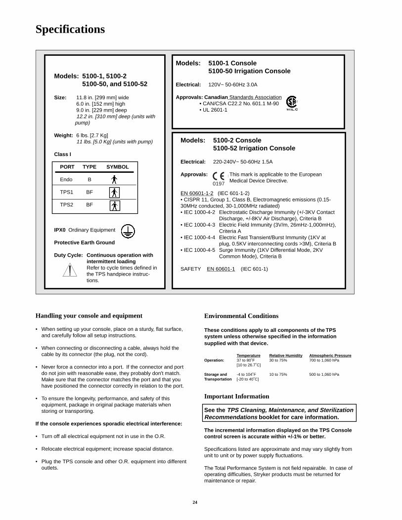
Specifications
Models: 5100-2 Console5100-52 Irrigation Console
Electrical: 220-240V~ 50-60Hz 1.5A
Approvals: This mark is applicable to the EuropeanMedical Device Directive.
EN 60601-1-2 (IEC 601-1-2)• CISPR 11, Group 1, Class B, Electromagnetic emissions (0.15-30MHz conducted, 30-1,000MHz radiated)• IEC 1000-4-2 Electrostatic Discharge Immunity (+/-3KV Contact
Discharge, +/-8KV Air Discharge), Criteria B• IEC 1000-4-3 Electric Field Immunity (3V/m, 26mHz-1,000mHz),
Criteria A• IEC 1000-4-4 Electric Fast Transient/Burst Immunity (1KV at
plug, 0.5KV interconnecting cords >3M), Criteria B• IEC 1000-4-5 Surge Immunity (1KV Differential Mode, 2KV
Common Mode), Criteria B
SAFETY EN 60601-1 (IEC 601-1)
Models: 5100-1 Console5100-50 Irrigation Console
Electrical: 120V~ 50-60Hz 3.0A
Approvals: Canadian Standards Association• CAN/CSA C22.2 No. 601.1 M-90• UL 2601-1
Models: 5100-1, 5100-25100-50, and 5100-52
Size: 11.8 in. [299 mm] wide6.0 in. [152 mm] high9.0 in. [229 mm] deep12.2 in. [310 mm] deep (units with
pump)
Weight: 6 lbs. [2.7 Kg]11 lbs. [5.0 Kg] (units with pump)
Class I
PORT TYPE SYMBOL
Endo B
TPS1 BF
TPS2 BF
IPX0 Ordinary Equipment
Protective Earth Ground
Duty Cycle: Continuous operation withintermittent loadingRefer to cycle times defined inthe TPS handpiece instruc-tions.
Handling your console and equipment
• When setting up your console, place on a sturdy, flat surface,and carefully follow all setup instructions.
• When connecting or disconnecting a cable, always hold thecable by its connector (the plug, not the cord).
• Never force a connector into a port. If the connector and portdo not join with reasonable ease, they probably don't match.Make sure that the connector matches the port and that youhave positioned the connector correctly in relation to the port.
• To ensure the longevity, performance, and safety of thisequipment, package in original package materials whenstoring or transporting.
If the console experiences sporadic electrical interference:
• Turn off all electrical equipment not in use in the O.R.
• Relocate electrical equipment; increase spacial distance.
• Plug the TPS console and other O.R. equipment into differentoutlets.
0197
Environmental Conditions
These conditions apply to all components of the TPSsystem unless otherwise specified in the informationsupplied with that device.
Temperature Relative Humidity Atmospheric PressureOperation: 37 to 80˚F 30 to 75% 700 to 1,060 hPa
[10 to 26.7˚C]
Storage and -4 to 104˚F 10 to 75% 500 to 1,060 hPaTransportation [-20 to 40˚C]
Important Information
See the TPS Cleaning, Maintenance, and SterilizationRecommendations booklet for care information.
The incremental information displayed on the TPS Consolecontrol screen is accurate within +/-1% or better.
Specifications listed are approximate and may vary slightly fromunit to unit or by power supply fluctuations.
The Total Performance System is not field repairable. In case ofoperating difficulties, Stryker products must be returned formaintenance or repair.
25
Repair and Loaner Program
This service is available in the United States only. Outside the U.S.A., contact your Stryker salesrepresentative or your nearest subsidiary listed on the last page.
On request, Stryker Instruments will provide a loaner unit for your use while repairs arebeing made.Please clean and sterilize all potentially contaminated products being sent in for repair,credit, or return of a loaner unit. The policy of Stryker Instruments is not to accept orprocess potentially contaminated products which do not meet this requirement.
Also, please be aware that it is unlawful to transport bio-contaminated products throughinterstate commerce which are not properly packaged and labeled as such.
1. Contact Stryker Customer Service at 1-800-253-3210 to request a loaner. Provide aname and address for shipping. Every effort will be made to send a loaner unit immediately.
2. Send the inoperative unit to Stryker with a purchase order number of authorization forrepair. The order should explain the nature of the difficulty. Also, provide a name andaddress for shipping the repaired instruments.
Return the inoperative unit to: Stryker InstrumentsRepair Department4100 E. MilhamKalamazoo, Michigan, 49001.
3. The repaired unit will be shipped back and the repair invoice will follow under separatecover. Under most conditions, repair turnaround time will be approximately 2-3 weeks.
4. As soon as your repaired unit is returned, return the loaner to Stryker Instruments.
Limited WarrantyFor all TPS products unless otherwise specified.In the U.S.A. only, products of Stryker Instruments are warranted to the original purchaser for a period of oneyear from the date of purchase, with exceptions noted below. Products are warranted to be free from defects inmaterial and workmanship. Abnormal wear and tear or damage caused by misuse or by failure to performnormal and routine maintenance as set out in the Maintenance Manual or Operating Instructions, or as demon-strated by an authorized Stryker Instruments representative, is not covered by the warranty. Any effort at fieldrepair or adjustment may invalidate your warranty.
The warranty extends to all purchasers and is limited to the repair or replacement of the product without chargewhen returned prepaid to Stryker Instruments. There are no other expressed warranties. This warranty givesyou specific legal rights and you may have other rights which vary by state and municipality.
For selected products.● Universal Handswitch is warranted for a period of 6 months from date of invoice.● Handpiece cords are warranted for a period of 6 months from date of invoice.● Cutting accessories are not warranted.

26
Stryker International Subsidiaries
European Authorized Rep: Phone: 33-1-48-17-50-00RA/QA Manager FAX: 33-1-48632175StrykerBP 50040-95946 Roissy CDGFrance
Stryker SA Phone: 41-21-963-87-01European Headquarters FAX: 41-21-963-87-0019, Avenue De Belmont1820 MontreuxSwitzerland
Stryker BV Phone: 31-4029-22522Marinums van Meeiweg 17 FAX: 31-4132-511355657 EN EindhovenThe NetherlandsMailing:PO Box 87475605 LS EindhovenThe Netherlands
Stryker Medical B.V. Phone: 31-4132-61555Nijverheidsstraat 2 FAX: 31-4132-52320Postbus 175405 AJ UdenThe Netherlands
Stryker Corp.- U.K.Branch Phone: 44-1635-262400Medway House FAX: 44-1635-5803005000 Newbury Business ParkLondon Road NewburyBerkshire, U.K. RG14 2ST
Stryker Deutschland GmbH Phone: 49-208-999060Gewerbeallee 18 FAX: 49-208-9990666D-45478 Mulheim an der RuhrGermany
Stryker France SARL Phone: 33-1-48-17-50-00BP 50040-95946 Roissy CDG FAX: 33-1-48632175France
Stryker Italy SRL Phone: 39-2-57512788Milanofiori FAX: 39-2-57500634Palazzo N420089 RozzanoMilano, Italy
Stryker Pacific, Limited Phone: 852-814-746310/F., Sungib Industrial Centre FAX: 852-873-021053 Wong Chuk Hang RoadAberdeen, Hong Kong
Stryker Australia Pty. Ltd. Phone: 61-2-439-5100Unit 20, 39 Herbert St. FAX: 61-2-439-6400St. Leonards NSW 2065PO Box 50Australia
Stryker Beijing Liaison Office Phone: 86-1-831-3388Room 2037, Xiyuan Hotel Extension: 2037Beijing, China FAX: 86-1-831-4577
Extension: 2037
Stryker Far East Inc., India Phone: 91-11-572-2407Flat-2A, Ashoka Chambers 91-11-573-2959B-5 Rajendra Park, Pusa Road FAX: 91-11-573-2959New Delhi 110060 India
Stryker Far East Inc., Singapore Phone: 65-287-8851Block 204, #04-103 65-287-8353Hougang Street 21 FAX: 65-382-3920Singapore 1953
Stryker Far East Inc., Taiwan Phone: 886-2-5014403Rm. 708, 7F, No. 147 FAX: 886-2-5099394Chien Kuo North RoadSection 2Taipei, Taiwan
Matsumoto Phone: 81-6203-2060Medical Instruments, Inc. FAX: 81-6202-35484-7 Awajimachi Nichome, Chuo-kuOsaka 541, Japan
Stryker Korea Limited Phone: 82-2-718-2972Room 1407, Guhsung Bldg. FAX: 82-2-718-2974541, Dohwa-Dong, Mapo-KuSeoul, Korea
Stryker Americas/Middle East Phone: 616-385-26002725 Fairfield Road 800-726-2725Kalamazoo, Michigan 49002 USA FAX: 616-385-1062Mailing Address:P.O. Box 4085Kalamazoo, Michigan 49003-4085 USA
Stryker Canada - Toronto Phone: 416-332-32353375 North Service Road FAX: 416-332-7674Unit C-9Burlington, OntarioCanada L7N362
Stryker Canada - Montreal Phone: 514-685-402472 3rd Avenue North FAX: 514-685-4024Roxboro, QuebecCanada H8Y 2L9

27

28
4100 E. Milham AvenueKalamazoo, Michigan U.S.A. 49001-6197(800) 253-3210Fax: 1-(800) 999-3811
European Authorized Rep: RA/QAManager
StrykerBP 50040-95946 Roissy CDGFrance
Phone: 33-1-48-17-50-00
5100-1-700 Rev-E7/98
Eur
opea
n eq
uiv.
510
0-1-
714
Rev
-BJa
pane
se e
quiv
. 510
0-1-
724
Rev
-B