instructions · 2015-02-23 · instructions youkits transmitter kit ... ic m4 screw 4 ic1 db107...
TRANSCRIPT

INSTRUCTIONS YOUKITS TRANSMITTER KIT
MODEL TT1A The 2-band TT1A transmitter is a 2-tube crystal controlled 2-band QRP CW transmitter
delivering around 4W. With the supplied crystals, TT2A works at 7.030 and 14.060. However, apart from the band switch, crystal sockets are used in the kit, offering a more flexible frequency switching. Crystals ranging from 60m – 20m can be plugged in to work without altering the tank coil.
Part List Symbol No Description Symbol No Description CAPACITORS MISCELLANEOUS C1, C3, C5, C6, C12
5600P / 1000V disc Tube Socket 2
C2 5600P, can be omitted C4, 100P / 1000V mica Crystal Socket 2 C7 1000P / 1000V mica Key Socket 3.5 mm pink C8 470uF / 16V electrolytic Mute Socket 3.5 mm green C9, C10, C11 0.1 CN1, CN2 Green Connector VC1, VC2 2 - 7P ceramic V-cap CN3 Band SW Connector CT1,CT2 365P air variable S1 S/R Switch TUBES S2 Band Switch V1 6N1 BNC Connector 2 V2 6P15 J3 Jump with a wire DIODES Tank Coil Form 25 Dia PPR Tube D1* 1N4752 + 1N4756 Solder Tag 2 D2, D3 1N4148 M3 Screw 8 IC M4 Screw 4 IC1 DB107 Brass Pillar 12mm, 2 RELAYS M3 Nut 4 RL1 TQ2-5V relay M3 Spring Spacer 2 RL2 5V relay M4 Spring Spacer 2 RESISTORS Power Connector 4-pin Aviation R1 47K / 1W Screen Plate R2 100 / 1W Shaft Coupler 3 R3 20K / 2W R4* 47 / 1W Shaft 3 R5 22K / 1W Enameled Wire R6 100 / 1W Hookup Wire R7 6.8K /2W CRYSTAL RF CHOKES Y1 7.030 MHz, 49S / U RFC1, RFC2 220uH Y2 14.060 MHz, 49S / U RFC3, RFC4 100uH colour code
1

Note: *Some kits are supplied with 49U crystals (taller package). With 49U crystals, no zener diodes are required at D1. R4 is 150 ohms.
2

CONSTRUCTION GUIDE Read this guide completely before starting work on your kit. It contains important
rk easier.
. Mount the two air variable capacitors to the screen plate. Insert a M4 spring spacer between plate and the capacitor so that the capacitor shaft is vertical
2. ntact the air capacitors.
pillars. It is easier to keep the holes in line if they are drilled along the red track. Caution! The
information that will make your wo
STEP-BY-STEP ASSEMBLY 1
the mounting holes of the screento the screen. Mount the band switch to the screen plate. Two solder tags of the wafer have to be bent so that they will not co
3. Drill two 3 mm holes in the tank form. These are the mounting holes for the 12 mm brass
tube surface is very slippery, and drilling bit tends to slide away if the 3 mm drill is used to start. Therefore, start the drilling work with a smaller drilling bit, say 1.8 - 2 mm, and then use the 3 mm drill. The smaller hole works as a guide, and the 3 mm drill would not slide. Fasten the two brass pillars to the form. Use a spring spacer on the screw head.
3
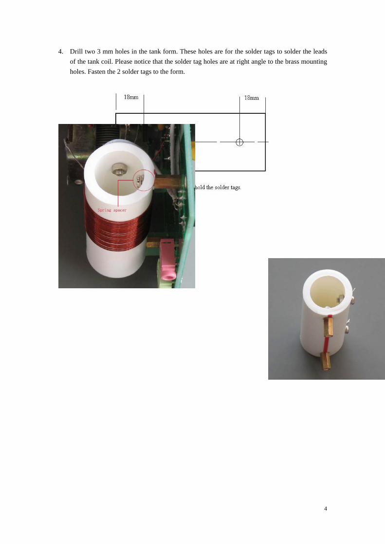
4. Drill two 3 mm holes in the tank form. These holes are for the solder tags to solder the leads of the tank coil. Please notice that the solder tag holes are at right angle to the brass mounting
holes. Fasten the 2 solder tags to the form.
4

5. Wind the tank coil, with about one wire space between turns (not very critical). Wind 21 turns with the supplied enameled wire. First, remove the enamel of around 10 mm from one end.
Tin this end, and then solder to one solder tag. Keep the wire tight while winding. Remove the enamel of the other end, tin and older to the tag. Count turns from the solder tag at the right side and tap at 10 turn. It is easy to tap. Remove some enamel with a knife at the tap position and tin. Solder a length of 55 mm tinned copper wire to the tinned tap point.
6. Solder components to the PCB. First, let us get to know some of the components:
5

Capacitors: 562 indicating 5600P. In some kits 5600P caps may be replaced with 103 (0.01uF). Both 562 and 103 work well in the kits.
Inductors: Color code 100uH used at RFC3 and 4; 220uH black inductor used at RFC1 and RFC2
nductors, diodes, BD107, and relays to the PCB. the bar of RL1. Never assembly it in the wrong
is “+”. d to the GND pad. The lead connected to th
able capacitor.
. RFC1 may be replaced with a 22k resistor. 7. Solder resistors, capacitors, tube sockets, i
Use crystal sockets at Y1 and Y2. Note direction. The longer lead of the 470uF cap
8. Solder VC1 and VC2. Solder the rotor lea e adjusting screw is the rotor lead of the vari
9. One
6

1N4752 (33V) and one 1N4756 (47V) are in series to make an 80V zener diode. No connector is needed at CN4. Connect the Send / Receive switch to the pads with wires. No connector is needed at J3 (DS1). Bridge J3 with wire
10. .
7
8
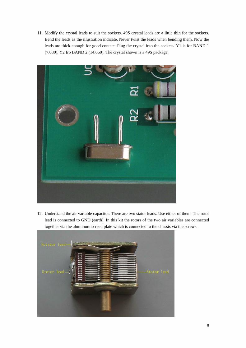
11. Modify the crystal leads to suit the sockets. 49S crystal leads are a little thin for the sockets. Bend the leads as the illustration indicate. Never twist the leads when bending them. Now the leads are thick enough for good contact. Plug the crystal into the sockets. Y1 is for BAND 1 (7.030), Y2 fro BAND 2 (14.060). The crystal shown is a 49S package.
12. Understand the air variable capacitor. There are two stator leads. Use either of them. The rotor
lead is connected to GND (earth). In this kit the rotors of the two air variab are connected together via the aluminum screen plate which is connected to the chassis via t e screws.
les h

13. Understand the band switch. This switch has four groups of contacts. Two groups are used in this kit.
CT2 (Underneath
e screen does not short-circuit the PCB tracks (One track runs HT!). If the screen edge is too ose to the PCB track, trim the edge a little to have enough clearance between the screen and t e tracks.
16. Wire the tank coil to the band switch and CT1 and CT2. The pad marked “A”
14. Solder a 220P/1000V mica capacitor across the stator and rotator leads of
CT2). Wire the band switch and CT2 as illustrated. 15. Assemble the screen assembly to the PCB assembly. Make sure that th
clh is connected to
the stator of CT1. The pad marked “B” is not used.
9

17. 18. e tank
19. r via the aluminum screen plate which is t the
20. rrent of V 0.1A,
incides wi
21. edge. N
2. Connect one BNC connector to ANT pads. This connector is the output and is connected to the antenna.
3. Connect one BNC connector to RX. This connector is connected to the receiver. When S/R switch is at S position, RL2 shifts ANT to RX port. The kit has a mute control voltage (MUTE) to supply around 6V which can be used to mute the receiver in case your receiver needs such a control voltage.
o CN2 via the
Connect a hookup wire between ANT ground pad and the rotator lead of CT2. The ANT output pad should be connected to the point where CT2 is connected to thcoil. In this kit the two air variables are connected togetheconnected to the chassis via the screws. An excellent arrangement would be to connectwo capacitors together with copper strip and connect them to earth at one point only. J3 is used to connect a 100mA meter, or a 100mA light bulb to observe the anode cu
2 while tuning up(Bulb rating less than 100mA is preferred. With the bulb of 6.3V only a week red dot can be observed when the tank is not resonant). The current dip co
th the maximum power. However, you can observe the power meter while tuning CT1.Connect the heaters of V1 and V2. The wires should be twisted and placed along the
ever place them near the grid of V1 or RL1.
2
2
24. Connect HT (210 – 300V DC) to CN1 and HEATER power (6.3V AC) taviation socket (Other type socket is fine). The supplied wires can be used for these purposes.
10

25. Assemble the shaft couplers and the shafts.
11

Solder a 220P across the stator and rotator leads of CT2
Connect MAINBOARD CN1 (HT) to the aviation connector; connect MAINBOARD CN2 (HEATER) to the aviation connector as indicated. You may define the pins in your own way. Connect this aviation connector to the power supply with 4 wires or a 4-wire cable.
12

POWER SUPPLY Power supply is not included in the kit. If you happen to have a power supply which has a
250 – 330V DC (70mA; 100mA is better) output and 6.3V AC (1.5A), you can use this kit now. However, if you do not have such a power supply at hand, you have to build it. The optional power supply kit does not include the power transformer.
Part List of the Optional Power Supply Kit Symbol No Description IC1 Rectifier, D2UB100 / D3UB100 C1 Electrolytic, 47uF / 450V R1 Resistor 220k / 2W F1 Fuse, 0.5A
Valve Technical Information 6N1 6P15 Heater Voltage 6.3V 6.3V Heater Current 600mA 760mA Anode Voltage 300V max 330V max Anode Current 7.5mA 30mA Anode Dissipation 2.2W max 12W max Screen Voltage -- 330V max When building the power supply, pay attention to the polarity of the 47uF capacitor, and the “+” and “-” leads of the rectifier bridge D2UB100. Never solder the leads in the wrong pads.
Connect CN1 (AC IN) to the transformer secondary
not contain the heater 6.3V
output leads (210 – 250V). Connect CN2 (HT OUT) to the aviation connector. CN2 supplies the filtered 250 – 330V DC to the transmitter. This board does
13

connectors. Please connect the 6.3V leads of the transformer to the aviation connector directly.
are used, one for the heater, the other heaters require around
1.36A rmer which supplies 5.7 – 7V (1.5A er with the secon 80V (100mA) should meet fact 70mA is OK). Two switc to operate the heater and HT separately. Turn on the heater first, and then turn on
According to the tube ratings, one 30 – 40W transformer with 6.3V and 210 – 250V secondary windings meet the requirement. In the diagram two transformers for the high voltage. The
. A small transfo) is enough. One transformdary ranging from 210 – 2
the requirement (Inhes are used
the HT after the heaters have been heated fully. In reality one transformer will do. In this case the heater
switch can be omitted. Turn on the power, both heater and HT are on. It all depends on what you can obtain whether to adopt the 2- transformer or 1-transformer plan. If the local mains is 110V, use 110V input transformer.
With the 47uF filter capacitor (C1), the rectified voltage is higher than the input AC. For example, the secondary is 220V AC. After it is rectified and smoothed, the output voltage without load is approximately 220V×1.414 = 311V. The voltage is too high? Do not worry. When the load is connected, the output is around 220V×1.2 = 264V.
14
ALIGNMENT AND USE CAUTION: This project is considerably sa
the builder must keep in mind. 1. The voltage used to power this kit can be2. Turn off the power supply and wait unt
circuit change is needed. 3. When testing and adjusting the operating
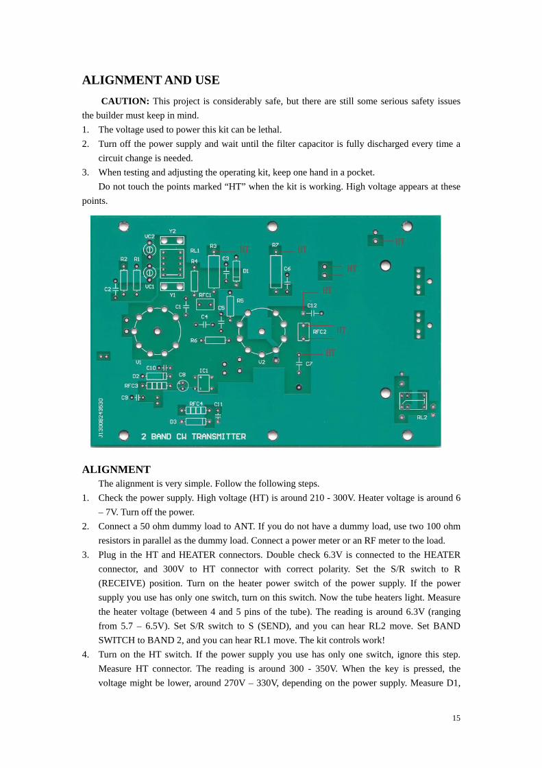
Do not touch the points marked “HT” wpoints.
H ater voltage is around 6 – 7V. Turn off the power.
2. Connect a 50 ohm dummy load to ANT. If you do not have a dumm load, use two 100 ohm resistors in parallel as the dummy load. Connect a power meter or an F meter to the load.
. Plug in the HT and HEATER connectors. Double check 6.3V is connected to the HEATER
voltage might be lower, around 270V – 330V, depending on the power supply. Measure D1,
fe, but there are still some serious safety issues
lethal. il the filter capacitor is fully discharged every time a
kit, keep one hand in a pocket. hen the kit is working. High voltage appears at these
ALIGNMENT
The alignment is very simple. Follow the following steps. 1. Check the power supply. High voltage (HT) is around 210 - 300V. e
yR
3connector, and 300V to HT connector with correct polarity. Set the S/R switch to R (RECEIVE) position. Turn on the heater power switch of the power supply. If the power supply you use has only one switch, turn on this switch. Now the tube heaters light. Measure the heater voltage (between 4 and 5 pins of the tube). The reading is around 6.3V (ranging from 5.7 – 6.5V). Set S/R switch to S (SEND), and you can hear RL2 move. Set BAND SWITCH to BAND 2, and you can hear RL1 move. The kit controls work!
4. Turn on the HT switch. If the power supply you use has only one switch, ignore this step. Measure HT connector. The reading is around 300 - 350V. When the key is pressed, the
15

the reading is around 85 – 90V. Note: D1 is not required if 49U crystals are used.
5. mum S”.
ear at . If er
can om
knob
. Press the key and tune CT1 to increase the power. Decrease CT2 a ay), and tune CT1 again for maximum power output. The maximum power
lower than that of 40m. You have
irp and make the crystal hot. It is a compromise.
r a
7.
Plug in the key to KEY socket. Set BAND SWITCH to BAND1. Set CT2 to maxicapacitance (Fully meshed, i.e. turn to the end counter-clockwise). Set S/R switch to “Press the key. Tune CT1 to increase the power output, and the maximum power will appone point. At this point, the anode current dips if you have a 100mA meter in inserted in J3a light bulb is inserted, it dims or goes out if a 6.3V 0.1A bulb is used. The maximum powoutput coincides with the current dip. If you do not have such a meter, do not worry. You observe the power meter while tune CT1. In reality, you can tell the maximum power frthe receiver. The monitored sound becomes stronger when the rig produces themaximum power. Now release the key. You have tested 40m. Mark the position of CT1 if you like. Set to BAND 2little (about half woutput coincides with the current dip. The output power istested 20m. The power output will be increased if the value of R4 is reduced. However, smaller value will cause ch
6. Set to BAND 1. Monitor the tone with a receiver. The note should stable, clean and almost perfect. If a serious constant frequency drift is noted in the long key test (holding the key fovery long time), some measure has to be taken to solve the drift. The frequency drift indicates too much heat is generated in the crystal and this crystal cannot withstand the heat. The oscillating level has to be limited. Solder a 22k resistor across the socket of Y1 to reduce the oscillating level. Set to BAND 2. Usually there is no such a problem as frequency drift in BAND 2, because the oscillating level is much lower relatively. The crystal frequency can be calibrated by adjusting VC1 and VC2.
CHIRP Without D1 the chirp tends to appear, unless 49U crystals are used. In this kit one 1N4752
16

andoscil d at D1, and
m
“
aximum power. For example, plug in a 5.320 crystal. What you have to do is to tune CT1. You n
14.0max
shou
EN encl Met
othe oles on the rear l
PCBMet Ass
one 1N4756 are combined to make an 80V zener for D1, stabilizing the power supply of the lator to suit 49S crystals. With 49U crystals, 1N4752 and 1N4756 are not require
in this case R4 should be increased to 150 ohms to reduce the oscillating level. R4 is also a chirp cure. Increase the value will improve the chirp. However, greater value would reduce the output power.
USING THE KIT
Connect ANT to the antenna. Connect the receiver antenna to RX. Set S/R switch to “R”. Now your receiver is connected to the antenna via RL2. Turn on the power. Unlike the transistor, the tube is not the turn-on-to-work device. Wait for 1 – 2 minutes for the tube to work. Set S/R switch to “S”, and your receiver is connected to the antenna. Press the key. Tune CT1 for the
aximum power output, which coincides with the anode current dip. If the current dip does not coincide with the power output, decrease CT2 and re-peak CT1. Now send CW codes. Blue light flashes through the small windows of V2 if the light is turned off in your room. Set S/R switch to R” immediately after the sending is finished. Wait for you luck!
WORKING ON OTHER METERBANDS
The frequency range for BAND 1 is 5 – 7.50MHz. 60m – 40m is covered. Simply pull out 7.030 crystal, and plug in a crystal ranging from 5 – 7.30MHz. Re-tune CT1 to produce the mdo ot have to change the band coil. That simple!
The frequency range for BAND 2 is 10 – 14.50MHz. 30m – 20m is covered. Simply pull out 60 crystal, and plug in a crystal ranging from 10 – 14.30MHz. Re-tune CT1 to produce the imum power. The kit works at 17 – 15m by changing the required crystals. However the tap of the tank coil ld be altered.
CLOSURE The enclosure is not included in this kit. However, it is not difficult to make a simple
osure, using wooden or metal plates.
hod 1: Use two pieces of wooden or metal plates measuring 105*51 mm, one as the front face, the
r the rear wall. Drill holes in the front face for the shaft to stick out. Drill hwa l for the BNC and aviation and 3.5 mm connectors. Mount the front face and rear wall to the
assembly. hod 2: Use four pieces of wooden plates or one piece metal sheeting to make a frame like structure.
emble the PCB to the frame.
17

Title
Num
ber
Revi
sion
Size A4
Dat
e:24
-Aug
-201
2Sh
eet
of
File
:D
:\ 新建文件夹
(2)\E
le2\
THU
ND
ER\T
h-B
PFD
.DD
BD
raw
n By
:
CT1
CT2
BAN
D S
W
S2
40M
20M
AN
T
RX
250
- 300
V
220P
/100
0V
L1
V1
MU
TE
KEY
AC1
V+2
AC 3
V- 4
IC1
D1C1
R1
R2
R3
R4
R5
R6
R7
C2
C3
C4
C5
C6
C7
C9
C10
C11
C12
VC
1V
C2
Y1
Y2
RFC
1
RFC
2 1 2 J3
45
45
6.3V
6.3V
1 2CN
2
HEA
TER
1 2CN
1
HT
C8
RFC
3
RFC
4
D2
D2
RL1
RL2
12
CN
4
S / R
1 2CN
3
BAN
D
To 4
, 5 o
f V1,
V2
1
2 3
7
23
9
2 BA
ND
TU
BE C
W T
RA
NSC
EIV
ER
CRY
STA
L SW
ITCH
ING
V2
1,6