(443 kb) - pier
TRANSCRIPT

Progress In Electromagnetics Research B, Vol. 44, 327–343, 2012
ANALYSIS OF AXIALLY MAGNETIZED PERMANENTMAGNET BEARING CHARACTERISTICS
S. I. Bekinal1, *, T. R. Anil1, and S. Jana2
1Department of Mechanical Engineering, Gogte Institute of Technol-ogy, Belgaum 590008, India2Propulsion Division, National Aerospace Laboratories, Bangalore560017, India
Abstract—The use of permanent magnets as bearings has gainedattention of researchers nowadays. The characteristics of forces andmoments have to be analysed thoroughly for the proper design ofpermanent magnet bearings. This paper presents a mathematicalmodel of an axially magnetized permanent magnet bearing (ringmagnets) using Coulombian model and a vector approach to estimatethe force, moment and stiffness. A MATLAB code is developedfor evaluating the parameters for five degrees of freedom (threetranslational and two rotational) of the rotor. Furthermore, itis extended to analyse stacked ring magnets with alternate axialpolarizations. The proposed model is validated with the availableliterature. Comparison of force and stiffness results of the presentedmodel with the results of three dimensional (3D) finite element analysisusing ANSYS shows good agreement. Finally, the cross coupledstiffness values in addition to the principal stiffness values are presentedfor elementary structures and also for stacked structures with three ringpermanent magnets.
1. INTRODUCTION
Permanent magnet bearings are contact free bearings wherein therotor is levitated using an attractive or repulsive forces generatedbetween the magnets. The contact free feature of permanent magnetbearings offers attractive advantages like friction free and lubricationfree operation, low maintenance, long life etc. Exhaustive work iscarried out by Yonnet [1, 2], Delamare et al. [3] for synthesizing
Received 9 August 2012, Accepted 24 September 2012, Scheduled 1 October 2012* Corresponding author: Siddappa Iranna Bekinal ([email protected]).

328 Bekinal, Anil, and Jana
different configurations of the magnetic bearings. These are usedin many applications such as flywheels, turbo molecular pumps,turbomachines and conveyor systems [4–7]. It is proposed that theforce and stiffness of the permanent magnet bearing can be increased iflayers of rings are stacked with specific magnetization pattern [8]. Theanalytical equations for calculating the magnetic field [9–14], force andstiffness [15–20] in bearings for both axial and radial magnetizationare widely available in the recent past. However in these works, thering magnets are concentric, which might not be prevailing in actualscenario. The expressions for evaluating the moments on the rotor in anaxially polarized bearings are presented by Jiang et al. [21, 22]. Theseanalytical expressions involve elliptical integrals which are tedious todeal. The present work focuses on the mathematical treatment forevaluating force, moment and stiffness characteristics of a permanentmagnet bearing considering three translational (x, y and z) and twoangular (ξ and γ) degrees of freedom of the rotor magnet ring using asimple vector approach [23]. A MATLAB code is written for estimatingthe forces, moments, stiffness and cross coupled stiffnesses between thestator-rotor made of two non-concentric ring magnets and for multiplerings based on the Coulombian model. The results of mathematicalmodel are compared with a case available in the literature [24] and withthe results of 3D finite element analysis using ANSYS. Finally, a full5 × 5 stiffness matrix (Eq. (1)) representing five degrees of freedomis developed for elementary structures of the bearings and stackedstructure with three ring permanent magnets.
K =
KXX KXY KXZ KXξ KXγ
KY X KY Y KY Z KY ξ KY γ
KZX KZY KZZ KZξ KZγ
KξX KξY KξZ Kξξ Kξγ
KγX KγY KγZ Kγξ Kγγ
(1)
2. FORCE, STIFFNESS AND MOMENT ESTIMATION
The forces between the two ring magnets, one fixed to the rotorand the other to the stator, need to be calculated to estimate thebearing characteristics. Two different methods, namely, a dipole andsurface charge density are used to calculate the forces between thetwo magnets. The dipole method is limited to specific cases, as thisprovides results for the dimensions of magnets which are equal to or lessthan the air gap. The latter method is used in the permanent magnetbearings where magnet dimensions are larger than the bearing rotor-stator gap, thereby utilized in the present analysis. In this method,

Progress In Electromagnetics Research B, Vol. 44, 2012 329
Figure 1. Configuration of permanent magnet bearing.
it is assumed that the permanent magnet surface is charged with apositive and negative charge according to the direction of polarization.The forces of attraction or repulsion between the polarized surfaces ofthe magnets are calculated using the Coulomb’s law of force. The basicconfiguration of a permanent magnet bearing is shown in Fig. 1.
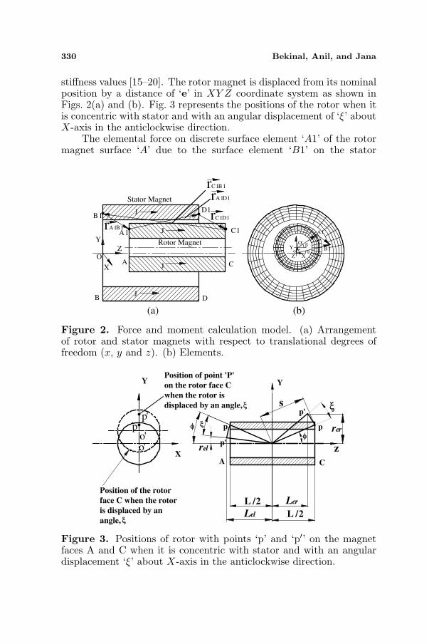
The inner magnet is fixed to the rotor and the stator to theouter magnet. In the present analysis it is assumed that the innermagnet can move in x, y and z translational directions and ξ andγ angular directions with respect to the outer magnet. The innerand outer radii of the inner permanent magnet ring are R1 and R2respectively. The inner and outer radii of the outer permanent magnetring are R3 and R4 respectively. The thicknesses of the outer and innermagnets are L = Z1 − Z0 and L = Z3 − Z2 respectively. Magneticpolarizations (J) of both the magnets are in the axial direction asdepicted by Fig. 1. Modeling of the bearing is carried out by knowingthe forces acting on the rotor magnet which in turn can be utilizedto estimate the bearing stiffness. The Coulombian model of themagnets is adopted, wherein each permanent magnet is represented bysurfaces with fictitious magnetic pole surface densities in the directionof polarization. Fig. 2(a) shows the arrangement of rotor and statormagnets with magnetization in the axial direction. Surfaces A and Care the fictitious charged surfaces of rotor magnet and surfaces B and Dare for the stator magnet. There are magnetic forces of attraction andrepulsion between the charged surfaces of the rotor and stator magnet.The net force acting is the bearing reactions for various positions ofthe rotor. In literature, analytical or semi-analytical expressions arederived and used for the purpose of calculating the bearing forces and
330 Bekinal, Anil, and Jana
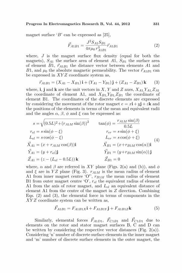
stiffness values [15–20]. The rotor magnet is displaced from its nominalposition by a distance of ‘e’ in XY Z coordinate system as shown inFigs. 2(a) and (b). Fig. 3 represents the positions of the rotor when itis concentric with stator and with an angular displacement of ‘ξ’ aboutX-axis in the anticlockwise direction.
The elemental force on discrete surface element ‘A1’ of the rotormagnet surface ‘A’ due to the surface element ‘B1’ on the stator
A1
B1
O'
e
X
Y
Z
β
αo
D
X
JB
J
J
J
ZO
C
Y
A
D1B1
A1 C1rA1B1
rA1D1
rC1B1
rC1D1
Rotor Magnet
Stator Magnet
(a) (b)
Figure 2. Force and moment calculation model. (a) Arrangementof rotor and stator magnets with respect to translational degrees offreedom (x, y and z). (b) Elements.
ξ
ξ
φ
φ
CA
p
p'
p'
p
Ler
Lel
rel
rer
s
Y
z
Y
Xo'o'
p'p
ξ
ξ
L / 2
L / 2
Position of the rotor
face C when the rotor
is displaced by an
angle,
Position of point 'P'
on the rotor face C
when the rotor is
displaced by an angle,
Figure 3. Positions of rotor with points ‘p’ and ‘p′’ on the magnetfaces A and C when it is concentric with stator and with an angulardisplacement ‘ξ’ about X-axis in the anticlockwise direction.
Progress In Electromagnetics Research B, Vol. 44, 2012 331
magnet surface ‘B’ can be expressed as [25],
~FA1B1 =J2SA1SB1
4πµ0 r3A1B1
~rA1B1 (2)
where, J is the magnet surface flux density (equal for both themagnets), SA1 the surface area of element A1, SB1 the surface areaof element B1, ~rA1B1 the distance vector between elements A1 andB1, and µ0 the absolute magnetic permeability. The vector ~rA1B1 canbe expressed in XY Z coordinate system as,
~rA1B1 = (XA1 −XB1) i + (YA1 − YB1) j + (ZA1 − ZB1)k (3)
where, i, j and k are the unit vectors in X, Y and Z axes, XA1,YA1,ZA1
the coordinate of element A1, and XB1,YB1,ZB1 the coordinate ofelement B1. The coordinates of the discrete elements are expressedby considering the movement of the rotor magnet e = xi+ yj+ zk andthe positions of the elements in terms of the mean and equivalent radiiand the angles α, β, φ and ξ can be expressed as:
s =√
(0.5L)2+(rA1M sin(β))2 tan(φ) =rA1M sin(β)
0.5Lrel = s sin(φ− ξ) rer = s sin(φ + ξ)Lel = s cos(φ− ξ) Ler = s cos(φ + ξ)~XA1 = (x + rA1M cos(β))i ~XB1 = (x+rB1M cos(α))i~YA1 = (y + rel)j ~YB1 = (y+rB1M sin(α)) j~ZA1 = (z − (Lel − 0.5L))k ~ZB1 = 0
(4)
where, α and β are referred in XY plane (Figs. 2(a) and (b)), and φand ξ are in Y Z plane (Fig. 3). rA1M is the mean radius of elementA1 from inner magnet centre ‘O′’, rB1M the mean radius of elementB1 from outer magnet centre ‘O’, rel the equivalent radius of elementA1 from the axis of rotor magnet, and Lel an equivalent distance ofelement A1 from the centre of the magnet in Z direction. CombiningEqs. (2) and (3), the elemental force in terms of components in theXY Z coordinate system can be written as,
~FA1B1 = FA1B1X i + FA1B1Y j + FA1B1Zk (5)
Similarly, elemental forces ~FA1D1, ~FC1B1 and ~FC1D1 due toelements on the rotor and stator magnet surfaces B, C and D canbe written by considering the respective vector distances (Fig. 2(a)).Considering ‘n’ number of discrete surface elements in the inner magnetand ‘m’ number of discrete surface elements in the outer magnet, the

332 Bekinal, Anil, and Jana
resultant forces in X, Y and Z axes, on the rotor magnet can beexpressed as a summation of all the elemental forces which is presentedbelow (Eqs. (6)–(8)).
FX =∑p=n, q=m
p=1, q=1FApBqX +
∑p=n, q=m
p=1, q=1FApDqX
+∑p=n, q=m
p=1, q=1FCpBqX +
∑p=n, q=m
p=1, q=1FCpDqX (6)
FY =∑p=n, q=m
p=1, q=1FApBqY +
∑p=n, q=m
p=1, q=1FApDqY
+∑p=n, q=m
p=1, q=1FCpBqY +
∑p=n, q=m
p=1, q=1FCpDqY (7)
FZ =∑p=n, q=m
p=1, q=1FApBqZ +
∑p=n, q=m
p=1, q=1FApDqZ
+∑p=n, q=m
p=1, q=1FCpBqZ +
∑p=n, q=m
p=1, q=1FCpDqZ (8)
The stiffness of the bearing in Cartesian coordinate system can beobtained by the numerical differentiation scheme, once the resultantforces are computed. A three-point midpoint formula for differentiationis used to obtain stiffness values in radial, axial and angular directions.In general, a three-point midpoint formula can be written as,
f ′ (X0) =12h
[f (X0 + h)− f (X0 − h)]− h2
6f (3) (ξ1) (9)
where ξ1 lies between (X0 − h) and (X0 + h).The principal radial stiffness exerted between two ring permanent
magnets along X direction at x can be expressed as follows:
KXX =dFX
dX=
12 ∆x
[FX (x + ∆x)− FX (x−∆x)]− ∆x
6
2
F 3X (ξ) (10)
where ξ lies between (x−∆x) and (x + ∆x) and for smaller values of∆x. Eq. (10) can be expressed as:
KXX∼= dFX
dX=
12 ∆x
[FX (x + ∆x)− FX (x−∆x)] (11)
Similarly, principal radial stiffness along Y and principal axial stiffnessin Z direction can be written as follows (Eqs. (12) and (13)):
KY Y∼= dFY
dY=
12 ∆y
[FY (y + ∆y)− FY (y −∆y)] (12)
KZZ∼= dFZ
dZ=
12 ∆z
[FZ (z + ∆z)− FZ (z −∆z)] (13)

Progress In Electromagnetics Research B, Vol. 44, 2012 333
Cross coupled radial and axial-radial stiffnesses can be expressed as(Eqs. (14)–(16)):
KXY = KY X∼= dFX
dY=
12 ∆y
[FX (x + ∆x)− FX (x−∆x)] (14)
KXZ = KZX∼= dFX
dZ=
12 ∆z
[FX (x + ∆x)− FX (x−∆x)] (15)
KY Z = KZY∼= dFZ
dY=
12 ∆y
[FZ (z + ∆z)− FZ (z −∆z)] (16)
Movements inside the bearing necessitates estimation of momentacting on the rotor. In practical cases the rotor magnet movementcan be assumed as a rigid body movement, thus the moment of theforces acting on the rotor magnet calculated about its centre of gravity(geometric centre for axisymmetric and isotropic magnets) providesuseful information about the dynamics of the rotor magnet. Themoment due to elemental force ~FA1B1 about the centre of gravity ofthe inner magnet can be written as,
MA1B1X = FA1B1Y × Lel + FA1B1Z × rel
MA1B1Y = FA1B1X × Lel − FA1B1Z × rA1M cos(β)MA1B1Z = −FA1B1X × rel + FA1B1Y × rA1M cos(β)
(17)
Similarly, the moments due to elemental forces ~FA1D1, ~FC1B1 and~FC1D1 about the centre of gravity of the rotor magnet can be writtenby following the proper sign convention.
The net moment acting on the rotor magnet are expressed usingEq. (17) as,
MX =∑p=n, q=m
p=1, q=1MApBqX +
∑p=n, q=m
p=1, q=1MApDqX
+∑p=n, q=m
p=1, q=1MCpBqX +
∑p=n, q=m
p=1, q=1MCpDqX (18)
MY =∑p=n, q=m
p=1, q=1MApBqY +
∑p=n, q=m
p=1, q=1MApDqY
+∑p=n, q=m
p=1, q=1MCpBqY +
∑p=n, q=m
p=1, q=1MCpDqY (19)
MZ =∑p=n, q=m
p=1, q=1MApBqZ +
∑p=n, q=m
p=1, q=1MApDqZ
+∑p=n, q=m
p=1, q=1MCpBqZ +
∑p=n, q=m
p=1, q=1MCpDqZ (20)
The principal moment stiffnesses exerted between the two ringpermanent magnets can be expressed as,
Kξξ = Kγγ∼= dMξ
dξ=
12 ∆ξ
[Mξ (ξ + ∆ξ)−Mξ (ξ −∆ξ)] (21)

334 Bekinal, Anil, and Jana
The cross coupled angular, axial-angular and radial-angular stiffnessescan be expressed as (Eqs. (22)–(25)):
Kξγ = Kγξ∼= dMξ
dγ=
12 ∆γ
[Mξ (ξ + ∆ξ)−Mξ (ξ −∆ξ)] (22)
KξZ = KZξ∼= dMZ
dξ=
12 ∆ξ
[MZ (Z + ∆Z)−MZ (Z −∆Z)] (23)
KξX = KXξ = KY γ = KγY∼= dMξ
dX
=1
2∆X[Mξ (ξ + ∆ξ)−Mξ (ξ −∆ξ)] (24)
KξY = KY ξ∼= dMξ
dY=
12 ∆Y
[Mξ (ξ + ∆ξ)−Mξ (ξ −∆ξ)] (25)
The forces and moment acting on the rotor magnet as well as theradial, axial and moment stiffness of the bearing for two differentconfigurations are calculated and presented in the following section.This mathematical model can be used for different configurations ofpermanent magnet bearings made of axially magnetized ring magnets.
3. VALIDATION OF PROPOSED MODEL
The proposed mathematical model is used to determine the axialforce and stiffness of an axially magnetized permanent magnet bearingshown in Fig. 1. Geometrical parameters considered for the analysisare presented in Table 1.
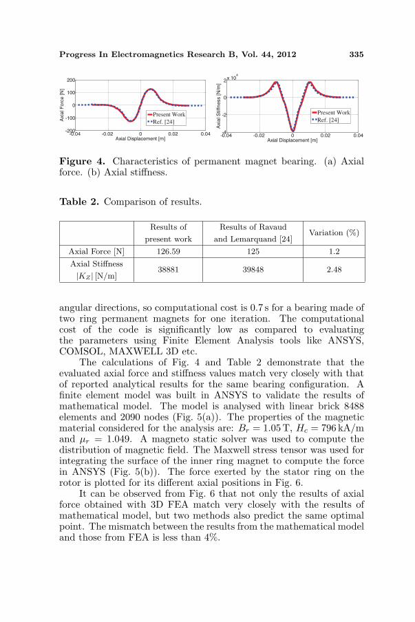
The inner magnet is placed in such a way that its magnetizationdirection is same as that of the stator magnet. This configurationproduces positive radial stiffness; however, axial stiffness becomesnegative. The axial force and stiffness values along with the resultsof [24] are graphed in Fig. 4. Table 2 presents a comparison of theproposed model with that reported in Ravaud and Lemarquand [24].MATLAB code developed for the mathematical model includes thecalculation of forces, stiffnesses and moments in axial, radial and
Table 1. Dimensions of the configuration.
Inner ring dimensions Outer ring dimensions
Inner radius [mm] R1 = 10 R3 = 22
Outer radius [mm] R2 = 20 R4 = 32
Thickness, L [mm] Z1− Z0 = 10 Z3− Z2 = 10
Flux density [T] J1 = 1 J2 = 1
Progress In Electromagnetics Research B, Vol. 44, 2012 335
-0.04 -0.02 0 0.02 0.04-200
-100
0
100
200
Axial Displacement [m]
Axia
l F
orc
e [N
]
Present Work
Ref. [24]
-0.04 -0.02 0 0.02 0.04-4
-2
0
2x 10
4
Axial Displacement [m]
Axia
l S
tiffn
ess [N
/m]
Present Work
Ref. [24]
Figure 4. Characteristics of permanent magnet bearing. (a) Axialforce. (b) Axial stiffness.
Table 2. Comparison of results.
Results of
present work
Results of Ravaud
and Lemarquand [24]Variation (%)
Axial Force [N] 126.59 125 1.2
Axial Stiffness
|KZ | [N/m]38881 39848 2.48
angular directions, so computational cost is 0.7 s for a bearing made oftwo ring permanent magnets for one iteration. The computationalcost of the code is significantly low as compared to evaluatingthe parameters using Finite Element Analysis tools like ANSYS,COMSOL, MAXWELL 3D etc.
The calculations of Fig. 4 and Table 2 demonstrate that theevaluated axial force and stiffness values match very closely with thatof reported analytical results for the same bearing configuration. Afinite element model was built in ANSYS to validate the results ofmathematical model. The model is analysed with linear brick 8488elements and 2090 nodes (Fig. 5(a)). The properties of the magneticmaterial considered for the analysis are: Br = 1.05T, Hc = 796 kA/mand µr = 1.049. A magneto static solver was used to compute thedistribution of magnetic field. The Maxwell stress tensor was used forintegrating the surface of the inner ring magnet to compute the forcein ANSYS (Fig. 5(b)). The force exerted by the stator ring on therotor is plotted for its different axial positions in Fig. 6.
It can be observed from Fig. 6 that not only the results of axialforce obtained with 3D FEA match very closely with the results ofmathematical model, but two methods also predict the same optimalpoint. The mismatch between the results from the mathematical modeland those from FEA is less than 4%.

336 Bekinal, Anil, and Jana
(a) (b)
Figure 5. Results of finite element analysis in ANSYS. (a) Finiteelement model of ring magnets. (b) Force exerted on the inner ring.
-0.01 -0.005 0-150
-100
-50
0
50
100
150
Mathematical model
3D FEA
Axial Displacement [m]
Ax
ial
Fo
rce
[N]
-0.005 -0.01
Figure 6. Axial force comparison.
4. ANALYSIS OF AXIALLY MAGNETIZED BEARINGCONFIGURATIONS
4.1. Elementary Structures
Two elementary configurations, as shown in Fig. 7 are analysed forforce, moment and stiffness parameters. The configuration in Fig. 7(a)is suitable for radial bearing application developing positive radialstiffness having negative axial stiffness. The configuration presentedin Fig. 7(b) is suitable for axial bearing application (positive axialstiffness and negative radial stiffness).
The axial force and stiffness computed for various axial positionsof the rotor magnet in the configurations I and II are presented in Fig. 8and Fig. 9 respectively. The axial force and stiffness are calculated atdifferent radial offset values (0.5, 0.75 and 1 mm) of the rotor magnetin the positive X direction.
The results presented in Figs. 8 and 9 show that there is a leastinfluence of radial offset on the axial force and stiffness values. Themoment acting on the rotor magnet as a result of radial displacements

Progress In Electromagnetics Research B, Vol. 44, 2012 337
Configuration I Configuration II
(a) (b)
Figure 7. Configurations of permanent magnet bearing. (a) Polariza-tion in the same direction. (b) Polarization in the opposite direction.
-0.03 -0.02 -0.01 0 0.01 0.02 0.03
-100
0
100
Axia
l F
orc
e[N
]
-6
-4
-2
0
2x10
4
Ax
ial
Sti
ffn
ess
[N/m
]
Axial Displacement [m] Axial Displacement [m]-0.03 -0.02 -0.01 0 0.01 0.02 0.03
0 mm
0.75 mm
0.5 mm
1 mm
0 mm
0.75 mm
0.5 mm
1 mm
(a) (b)
Figure 8. Characteristics of configuration I. (a) Axial force. (b) Axialstiffness.
-200
-100
0
100
200
Ax
ial
Forc
e[N
]
-2
0
2
4
6x10
4
Ax
ial
Stiff
nes
s[N
/m]
-0.03 -0.02 -0.01 0 0.01 0.02 0.03Axial Displacement [m]
(a)
-0.03 -0.02 -0.01 0 0.01 0.02 0.03Axial Displacement [m]
(b)
0 mm
0.75 mm
0.5 mm
1 mm
0 mm
0.75 mm
0.5 mm
1 mm
Figure 9. Characteristics of configuration II. (a) Axial force. (b)Axial stiffness.
(0.5, 0.75 and 1 mm) are calculated as a function of various axialpositions of the rotor for configurations I and II and are plotted inFig. 10.
It has been observed from analysis that the radial displacementof the rotor in X-axis generates moment about the Y -axis of therotor magnet and vice-versa. The resultant moment about the Z-axisof the rotor magnet is zero. The results show that the magnitudesof moment increase with the higher radial offset value in both the

338 Bekinal, Anil, and Jana
configurations and they vanish when the inner magnet is concentricwith the outer magnet. Direction of the moment changes accordingto the magnetization direction of the inner magnet with respect to theouter magnet. The radial forces and stiffness values of both the bearingconfiguration are calculated as a function of radial displacement andare presented in Fig. 11.
The results shown in Fig. 11 demonstrate that the bearingconfiguration I generates positive radial stiffness and configuration IIgenerates negative radial stiffness showing a similar trend as cited byearlier researcher [3]. A full 5 × 5 stiffness matrix at an axial offsetof 2.8 mm for the configuration I is presented in Table 3. The angulardisplacements of the rotor ξ about X-axis and γ about Y -axis areconsidered when the rotor is radially centred.
The calculations shown in Table 3 demonstrate that no crosscoupling of stiffnesses between X and Y as well as between ξ andγ directions. Results of configuration II are obtained by changing thesign of respective cell values of Table 3.
Mo
me
nt
abou
t Y
axis
[Nm
]
Mo
ment
abou
t Y
axis
[Nm
]
-0.03 -0.02 -0.01 0 0.01 0.02 0.03Axial Displacement [m]
(a)
-0.03 -0.02 -0.01 0 0.01 0.02 0.03Axial Displacement [m]
(b)
0.06
0.04
0.02
0
-0.02
-0.04
-0.06
0.06
0.04
0.02
0
-0.02
-0.04
-0.06
0 mm
0.75 mm
0.5 mm
1 mm
0 mm
0.75 mm
0.5 mm
1 mm
Figure 10. Moment about Y -axis at various radial displacements inX-axis. (a) Configuration I. (b) Configuration II.
-2 -1.5 -1 -0.5 0 0.5 1 1.5 2-50
-40
-30
-20
-10
0
10
20
30
40
50
-3
-2
-1
0
1
2
3x10
4
Radial Displacement [mm]
Rad
ial
Fo
rce
[N]
Rad
ial
Sti
ffn
ess
[N/m
]
-2 -1.5 -1 -0.5 0 0.5 1 1.5 2
Configuration I
Configuration II
Configuration I
Configuration II
Radial Displacement [mm]
(a) (b)
Figure 11. Characteristics of configuration I and II. (a) Radial force.(b) Radial stiffness.

Progress In Electromagnetics Research B, Vol. 44, 2012 339
Table 3. Results of configuration I.
X Y Z ξ γ
X 11.3N/mm 0 * 0 0
Y 0 11.3N/mm ** 0 0
Z * ** −22.61N/mm # ##
ξ 0 0 # −1.15Nm/rad 0
γ 0 0 ## 0 −1.15Nm/rad
where ∗ = −2.03N/mm at x = 0.5mm # = 179.8 Nm/rad at ξ = 10◦
= −3.99N/mm at x = 1.0 mm = 191.8Nm/rad at ξ = 15◦
= −5.98N/mm at x = 1.5mm, = 195Nm/rad at ξ = 20◦
∗∗ = −2.03N/mm at y = 0.5mm ## = 179.8Nm/rad at γ = 10◦
= −3.99N/mm at y = 1.0mm = 191.8Nm/rad at γ = 15◦
= −5.98N/mm at y = 1.5mm, = 195 Nm/rad at γ = 20◦.
Figure 12. Cross-section view of a permanent magnet bearingcomposed of three ring pairs with alternate axial polarizations: R1 =10mm, R2 = 20mm, R3 = 22 mm, R4 = 32mm, J = 1T, the heightof each ring permanent magnet = 10mm.
4.2. Stacked Structures with Three Ring PermanentMagnets
The configuration composed of three ring pairs with alternate axialpolarizations is presented in Fig. 12. The variation of axial forceand stiffness of the configuration with radial offset for different axialpositions of the rotor is depicted by Fig. 13.
The proposed mathematical approach leads to following observa-tions:

340 Bekinal, Anil, and Jana
0 mm
0.5 mm
0.75 mm
1 mm
-0.04 -0.03 -0.02 -0.01 0 0.01 0.02 0.03 0.04-600
-400
-200
0
200
400
600
-2
-1
0
1
2x10
5
Axial Displacement [m]-0.04 -0.03 -0.02 -0.01 0 0.01 0.02 0.03 0.04
Axial Displacement [m]
0 mm
0.75 mm
0.5 mm
1 mm
Ax
ial
Forc
e[N
]
Ax
ial
Stiff
nes
s[N
/m]
(a) (b)
Figure 13. Characteristics of permanent magnet bearing made ofthree ring pairs. (a) Axial force. (b) Axial stiffness.
-0.04 -0.03 -0.02 -0.01 0 0.01 0.02 0.03 0.04-0.5-0.4
-0.3
-0.2
-0.1
0
0.1
0.2
0.3
0.40.5
Axial Displacement [m]
Mo
men
t ab
ou
t Y
ax
is [
Nm
]
0 mm
0.5 mm
0.75 mm1 mm
Figure 14. Moment about Y -axis at various radial displacements inX-axis.
• The maximum axial force exerted by the outer rings on the innerrings = 544N and maximum axial stiffness, |KZ | = 183990 N/m(for concentric rings).
• For a radial offset of 1 mm in X direction, maximum force =552.85N and stiffness, |KZ | = 193300 N/m.
Negative axial stiffness implies, suitability for radial bearingapplication. The moment acting on the rotor magnet as the resultof radial displacements are plotted in Fig. 14. The maximum momentacting on the rotor about Y -axis is estimated as 0.4Nm for a radialoffset of 1mm in X direction. A full 5× 5 stiffness matrix at an axialoffset of 3.0 mm for the configuration shown in Fig. 12 is presented inTable 4. The angular displacements of the rotor ξ about X-axis and γabout Y -axis are considered when the rotor is radially centred.

Progress In Electromagnetics Research B, Vol. 44, 2012 341
Table 4. Results of configuration composed of three ring pairs withalternate axial polarizations (Fig. 12).
X Y Z ξ γ
X 49.73N/mm 0 * 0 0
Y 0 49.73N/mm ** 0 0
Z * ** −99.46N/mm # ##
ξ 0 0 # −34Nm/rad 0
γ 0 0 ## 0 −34Nm/rad
where ∗ = −9.79N/mm at x = 0.5 mm # = 1077.8Nm/rad at ξ = 10◦
= −20N/mm at x = 1.0mm = 1088Nm/rad at ξ = 15◦
= −30N/mm at x = 1.5mm, = 1571Nm/rad at ξ = 20◦
∗∗ = −9.79N/mm at y = 0.5mm ## = 1077.8Nm/rad at γ = 10◦
= −20N/mm at y = 1.0mm = 1088Nm/rad at γ = 15◦
= −30N/mm at y = 1.5mm, = 1571Nm/rad at γ = 20◦.
5. CONCLUSION
A simple mathematical formulation employing the Coulombian modelusing a vector approach is presented for the investigation of forces(radial and axial), moments on the rotor and stiffness of a permanentmagnet bearing. Comparison of the results obtained for an axiallymagnetized permanent magnet bearing with that reported in theliterature and 3D FEA shows very good agreement. An attempt hasbeen made to determine the effect of radial and axial displacementsof the rotor on force, stiffness and moment in a permanent magnetbearing. It is observed that the effect of radial displacement on theforce and stiffness is least, whereas on the moment is quite prominent(magnitude of moment about X or Y -axis increases with the higherradial offset value). The magnitude of moment increases with anincrease in the number of rings in the stack. Full evaluation of thepermanent magnet bearing performance is presented by calculating5 × 5 stiffness matrix representing five degrees of freedom. Thepresented work can be used for optimizing the design of an axiallymagnetized permanent magnet bearing for wide applications and also,this method involves less computations than the approaches utilizingelliptical integrals.
342 Bekinal, Anil, and Jana
REFERENCES
1. Yonnet, J. P., “Passive magnetic bearings with permanentmagnets,” IEEE Trans. Magn., Vol. 14, No. 5, 803–805, 1978.
2. Yonnet, J. P., “Permanent magnetic bearings and couplings,”IEEE Trans. Magn., Vol. 17, No. 1, 1169–1173, 1981.
3. Delamare, J., E. Rulliere, and J. P. Yonnet, “Classification andsynthesis of permanent magnet bearing configurations,” IEEETrans. Magn., Vol. 31, No. 6, 4190–4192, 1995.
4. Chu, H. Y., Y. Fan, and C. S. Zhang, “A novel design forthe flywheel energy storage system,” Proceedings of the EighthInternational Conference on Electrical Machines and Systems,Vol. 2, 1583–1587, 2005.
5. Guilherme, G. S., R. Andrade, and A. C. Ferreira, “Magneticbearing sets for a flywheel system,” IEEE Trans. on AppliedSuperconductivity, Vol. 17, No. 2, 2150–2153, 2007.
6. Ohji, T., et al., “Conveyance test by oscillation and rotation to apermanent magnet repulsive-type conveyor,” IEEE Trans. Magn.,Vol. 40, No. 4, 3057–3059, 2004.
7. Hussien, A., et al., “Application of the repulsive-type magneticbearing for manufacturing micromass measurement balanceequipment,” IEEE Trans. Magn., Vol. 41, No. 10, 3802–3804,2005.
8. Yonnet, J. P., et al., “Stacked structures of passive magneticbearings,” J. Appl. Phys., Vol. 70, No. 10, 6633–6635, 1991.
9. Ravaud, R., G. Lemarquand, and R. Lemarquand, “Analyticalcalculation of the magnetic field created by permanent magnetrings,” IEEE Trans. Magn., Vol. 44, No. 8, 1982–1989, 2008.
10. Babic, S. I. and C. Akyel, “Improvement in the analyticalcalculation of the magnetic field produced by permanent magnetrings,” Progress In Electromagnetics Research C, Vol. 5, 71–82,2008.
11. Ravaud, R. and G. Lemarquand, “Comparison of the Coulombianand Amperian current models for calculating the magnetic fieldproduced by radially magnetized arc-shaped permanent magnets,”Progress In Electromagnetics Research, Vol. 95, 309–327, 2009.
12. Ravaud, R., G. Lemarquand, V. Lemarquand, and C. Depollier,“Discussion about the analytical calculation of the magnetic fieldcreated by permanent magnets, ” Progress In ElectromagneticsRe-search B, Vol. 11, 281–297, 2009.
13. Ravaud, R., G. Lemarquand, and V. Lemarquand, “Magnetic fieldcreated by tile permanent magnets,” IEEE Trans. Magn., Vol. 45,
Progress In Electromagnetics Research B, Vol. 44, 2012 343
No. 7, 2920–2926, 2009.14. Selvaggi, J. P., et al., “Calculating the external magnetic field
from permanent magnets in permanent-magnet motors — Analternative method,” IEEE Trans. Magn., Vol. 40, No. 5, 3278–3285, 2004.
15. Lang, M., “Fast calculation method for the forces and stiffnessesof permanent-magnet bearings,” 8th International Symposium onMagnetic Bearing, 533–537, 2002.
16. B. Paden, N. Groom, and J. Antaki, “Design formulas forpermanent-magnet bearings,” ASME Trans., Vol. 125, 734–739,2003.
17. Azukizawa, T., S. Yamamoto, and N. Matsuo, “Feasibility studyof a passive magnetic bearing using the ring shaped permanentmagnets,” IEEE Trans. Magn., Vol. 44, No. 11, 4277–4280, 2008.
18. Samanta, P. and H. Hirani, “Magnetic bearing configurations:Theoretical and experimental studies,” IEEE Trans. Magn.,Vol. 44, No. 2, 292–300, 2008.
19. Ravaud, R., G. Lemarquand, and V. Lemarquand, “Force andstiffness of passive magnetic bearings using permanent magnets.Part 1: Axial magnetization,” IEEE Trans. Magn., Vol. 45, No. 7,2996–3002, 2009.
20. Ravaud, R., G. Lemarquand, and V. Lemarquand, “Force andstiffness of passive magnetic bearings using permanent magnets.Part 2: Radial magnetization,” IEEE Trans. Magn., Vol. 45,No. 9, 3334–3342, 2009.
21. Jiang, W., et al., “Forces and moments in axially polarized radialpermanent magnet bearings,” Proceedings of Eighth InternationalSymposium on Magnetic Bearings, Mito, Japan, 521–526, 2002.
22. Jiang, W., et al., “Stiffness analysis of axially polarized radialpermanent magnet bearings,” Proceedings of Eighth InternationalSymposium on Magnetic Bearings, Mito, Japan, 527–532, 2002.
23. Bekinal, S. I., T. R. Anil, and S. Jana, “Force, momentand stiffness characteristics of permanent magnet bearings,”Proceedings of National Symposium on Rotor Dynamics, IndianInstitute of Technology, Madras, India, 161–168, 2011.
24. Ravaud, R. and G. Lemarquand, “Halbach structures forpermanent magnets bearings,” Progress In ElectromagneticResearch M, Vol. 14, 263–277, 2010.
25. Mukhopadhaya, S. C., et al., “Fabrication of a repulsive-type magnetic bearing using a novel arrangement of permanentmagnets for vertical-rotor suspension,” IEEE Trans. Magn.,Vol. 39, No. 5, 3220–3222, 2003.