© boardworks ltd 2010 1 of 24 electric circuits. © boardworks ltd 2010 2 of 24 teacher’s notes...
TRANSCRIPT
© Boardworks Ltd 20101 of 24
Electric Circuits

© Boardworks Ltd 20102 of 24
Teacher’s notes included in the Notes Page
Flash activity (these activities are not editable) Virtual experiment
Accompanying worksheet
For more detailed instructions, see the Getting Started presentation

© Boardworks Ltd 20103 of 24
What is an electric circuit?
At the beginning of the lesson, your teacher had to press a switch to turn the interactive whiteboard on. Pressing the switch completed an electric circuit.
Look around you now. What objects can you see that contain electric circuits?
An electric circuit is made up of the following:
a source of electricity, such as a battery
a conducting material, usually a wire, through which electricity can flow
a component to use some of the electricity, such as a light bulb
a switch to break the circuit.
© Boardworks Ltd 20104 of 24
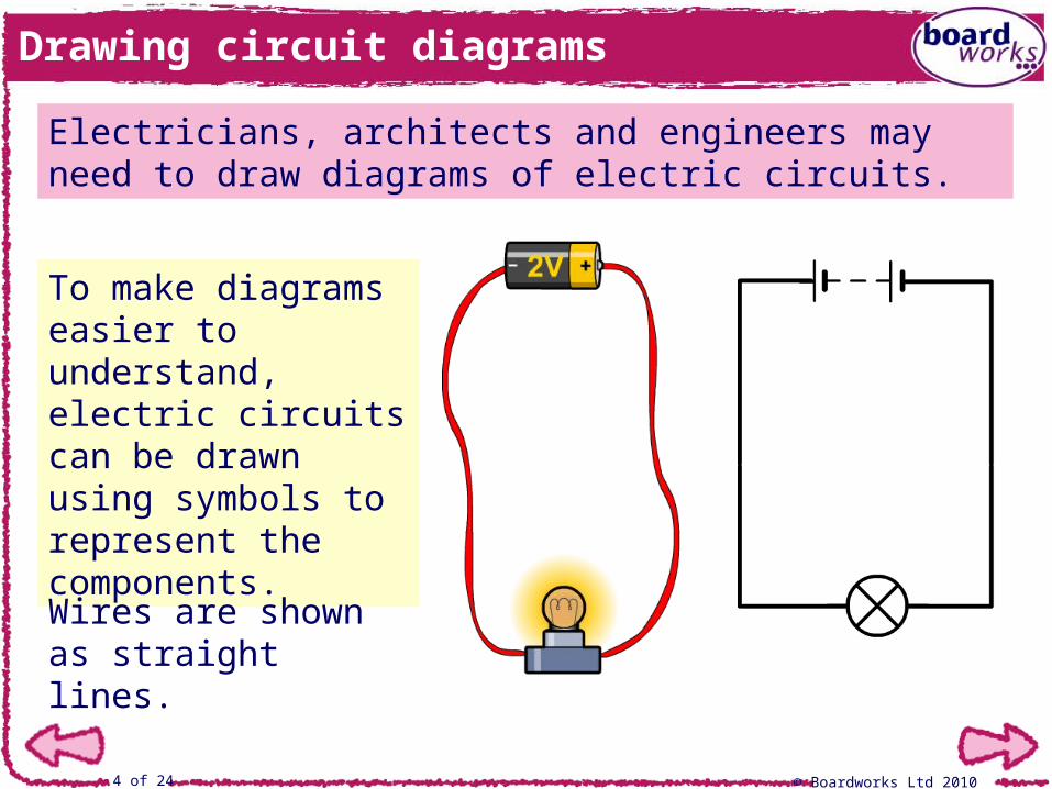
Drawing circuit diagrams
Electricians, architects and engineers may need to draw diagrams of electric circuits.
To make diagrams easier to understand, electric circuits can be drawn using symbols to represent the components.
Wires are shown as straight lines.

© Boardworks Ltd 20105 of 24
Circuit symbols

© Boardworks Ltd 20106 of 24
What is current?
Current is a measure of how much electric charge flows through a circuit. The more charge that flows, the larger the current.
Current is measured using an ammeter, which must be connected in series in the circuit.
When two or more circuit components are connected in series, the same current flows through each component.
The units for current are amps (A).
© Boardworks Ltd 20107 of 24
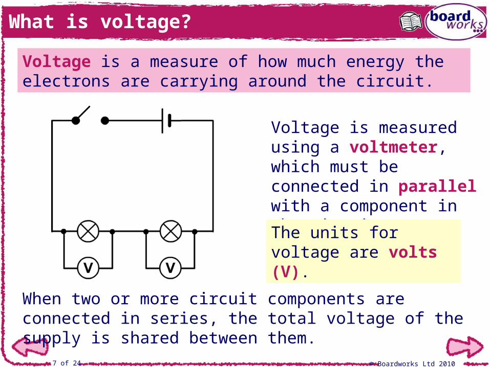
What is voltage?
Voltage is a measure of how much energy the electrons are carrying around the circuit.
When two or more circuit components are connected in series, the total voltage of the supply is shared between them.
Voltage is measured using a voltmeter, which must be connected in parallel with a component in the circuit.
The units for voltage are volts (V).
© Boardworks Ltd 20108 of 24
Current and voltage in series circuits

© Boardworks Ltd 20109 of 24
Case study: electricity and the heart
Most of the body is controlled by electrical impulses from the brain or different organs. A small area within the heart, called the sinoatrial node (SAN), controls its beating.
Sometimes the rhythm of the heart can be disrupted – beating too quickly or in an uncontrolled way. This can lead to death if a normal rhythm isn’t established quickly.
A defibrillator can be used to shock the heart into re-establishing a normal rhythm. Unsynchronized current flows from the defibrillator into the heart, causing it to momentarily stop beating. It can then restart with a more controlled rhythm.

© Boardworks Ltd 201010 of 24
© Boardworks Ltd 201011 of 24
What is resistance?
© Boardworks Ltd 201012 of 24
Factors affecting resistance
© Boardworks Ltd 201013 of 24
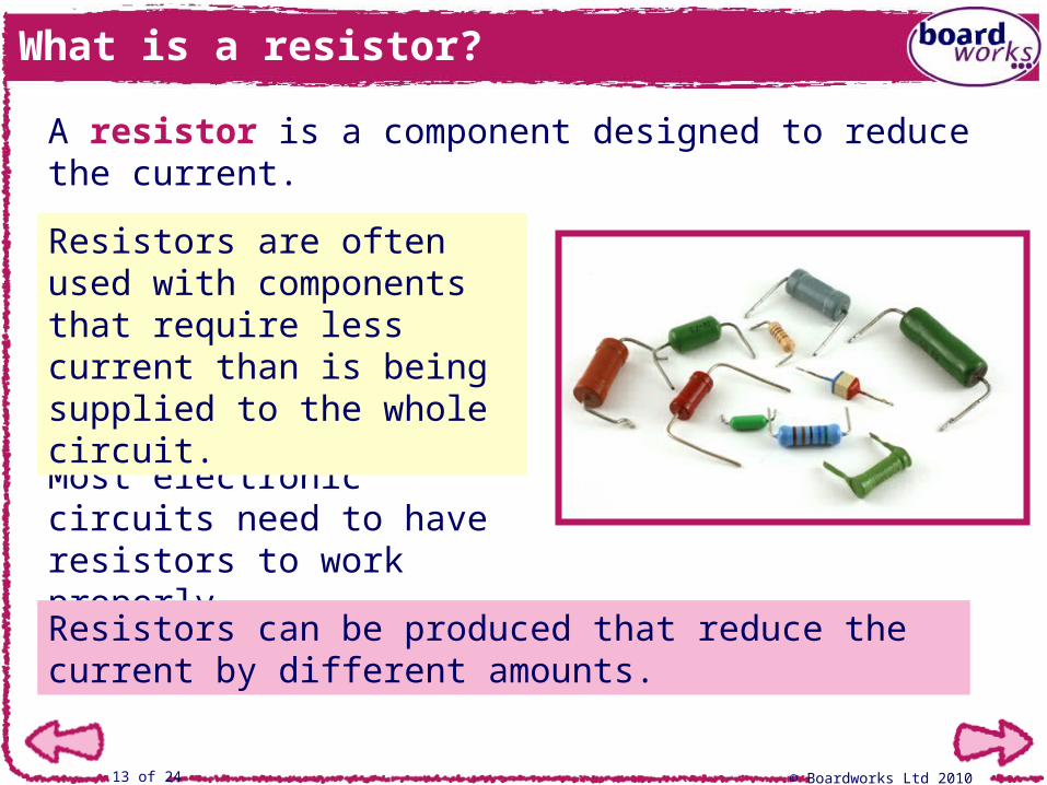
What is a resistor?
A resistor is a component designed to reduce the current.
Most electronic circuits need to have resistors to work properly.
Resistors are often used with components that require less current than is being supplied to the whole circuit.
Resistors can be produced that reduce the current by different amounts.

© Boardworks Ltd 201014 of 24
True or false?

© Boardworks Ltd 201015 of 24
Case study: the heating effect of resistance
High resistance in a wire can produce heat.
Resistance is important in a filament light bulb. The filament is made from a very thin, long piece of high resistance wire. The resistance is so high that when electricity flows through the wire, it glows ‘white hot’ and emits light.
Electricity is transmitted across the country with a very high voltage and a low current. This reduces the resistance in the wire and the heat produced.
© Boardworks Ltd 201016 of 24
© Boardworks Ltd 201017 of 24
Ohm’s law
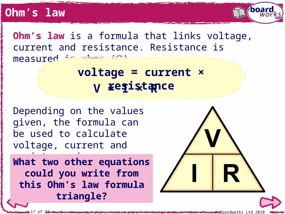
Depending on the values given, the formula can be used to calculate voltage, current and resistance in a circuit.
Ohm’s law is a formula that links voltage, current and resistance. Resistance is measured in ohms ().
What two other equations could you write from this
Ohm’s law formula triangle?
voltage = current × resistance
V = I × R
© Boardworks Ltd 201018 of 24
What does Ohm’s law mean?
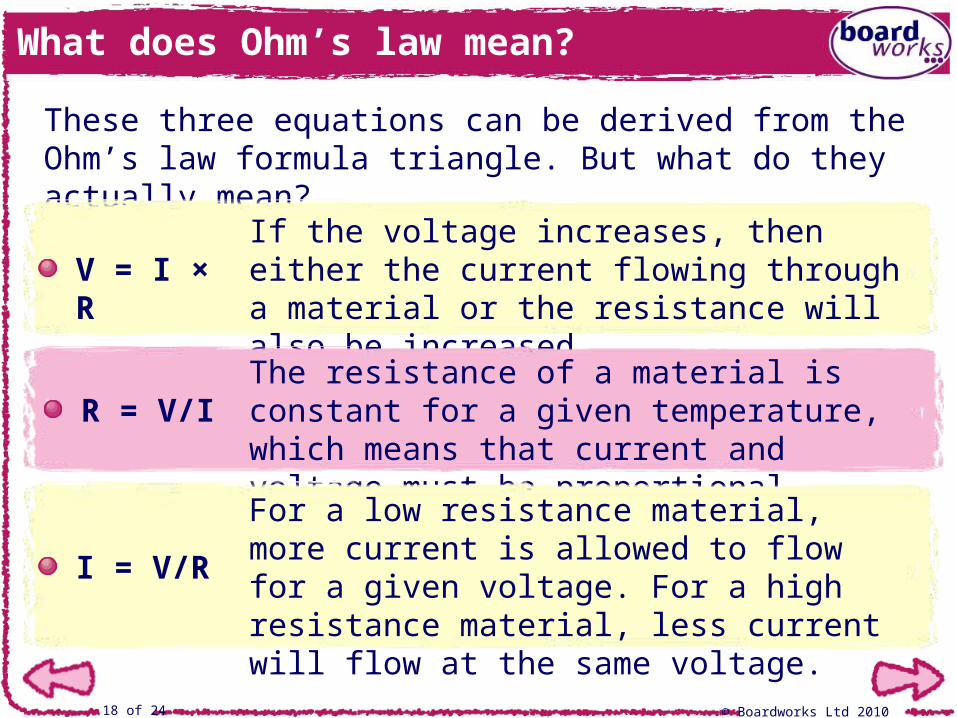
These three equations can be derived from the Ohm’s law formula triangle. But what do they actually mean?
If the voltage increases, then either the current flowing through a material or the resistance will also be increased.
V = I × R
R = V/IThe resistance of a material is constant for a given temperature, which means that current and voltage must be proportional.
I = V/R
For a low resistance material, more current is allowed to flow for a given voltage. For a high resistance material, less current will flow at the same voltage.

© Boardworks Ltd 201019 of 24
Ohm’s law calculations

© Boardworks Ltd 201020 of 24
Using Ohm’s law
Ohm’s law can be used to calculate the resistance of a component in a circuit.
Which equation would you use to calculate resistance?
It is difficult to measure the resistance of a component in a circuit directly, so it is usually done by measuring the voltage and current through the component instead.
Which instrument would be used to measure the current?
Which instrument would be used to measure the voltage?
R = V/I
voltmeter
ammeter
© Boardworks Ltd 201021 of 24
Investigating resistors
© Boardworks Ltd 201022 of 24
Case study: dimmer switches
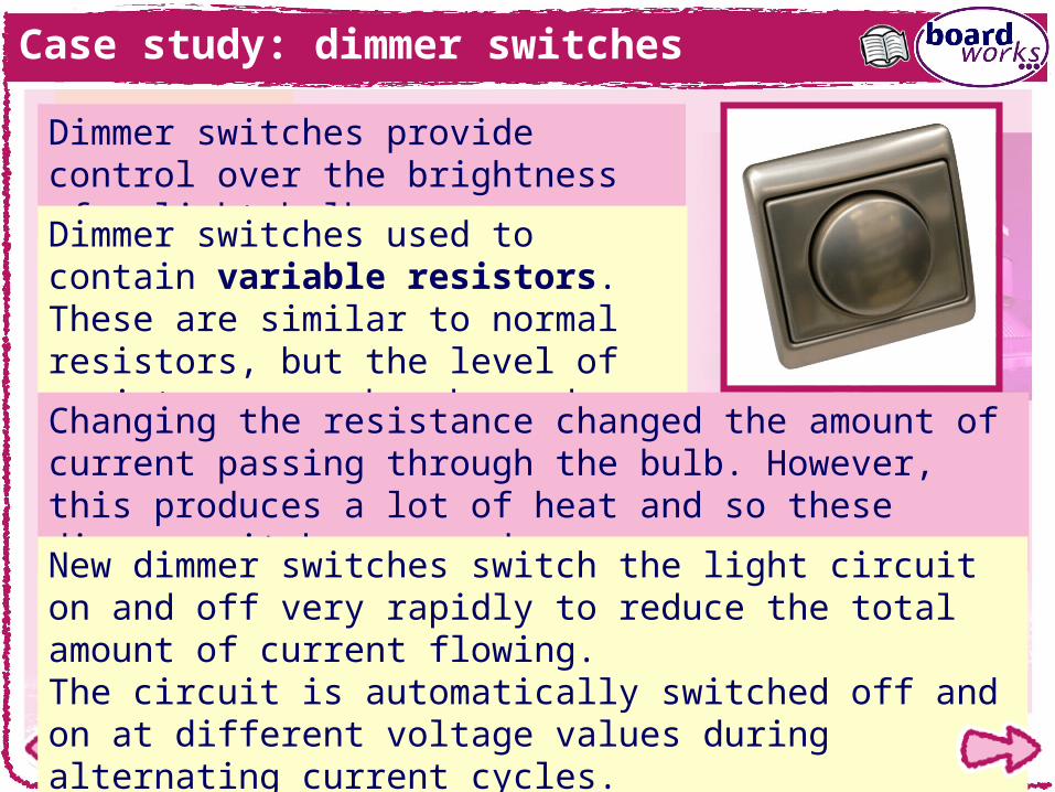
Dimmer switches provide control over the brightness of a light bulb.
Dimmer switches used to contain variable resistors. These are similar to normal resistors, but the level of resistance can be changed.
Changing the resistance changed the amount of current passing through the bulb. However, this produces a lot of heat and so these dimmer switches were dangerous.
New dimmer switches switch the light circuit on and off very rapidly to reduce the total amount of current flowing. The circuit is automatically switched off and on at different voltage values during alternating current cycles.

© Boardworks Ltd 201023 of 24
You are an electrical engineer and have been asked to train some new employees.
You should include the following:
a brief description of how a voltmeter and ammeter are used in a circuit to measure voltage and current
a diagram of a series circuit showing how to measure the current and voltage across the battery and another component
an explanation of how to use Ohm’s law to calculate resistance, current and voltage, with worked examples.
Prepare a handout about Ohm’s law and electric circuits.

© Boardworks Ltd 201024 of 24
Multiple-choice quiz