com · changes in the insulating materials insuri.'1g a tighter structure, contributing to...
TRANSCRIPT

Westinghouse
•
Network Grid System
Network � /"�
Primary Feeder
TrtlnSforrner -;?"'-� ) <!f/4-VoOlt
"{ .... ;..........;..........----+--+--........ -+-�*- Nefwatk
Prtlleclor
Descriptive Bulletin 47-150 Page 1
Spacemiser liquid-Immersed Network Transformers
300 to 2500 Kva, Three Phase, 60 Hertz, HV: 2400 to 34500 volts, LV: 216Y /125 or 480Y /277 volts Vault and Subway
Application The Westinghouse Spacemiser Network transformer, as pictured, is designed for use in grid type secondary network systems. These systems are most commonly used where there exists a high load density such as in metropolitan areas,
A typical example of a grid system using this type of transformer is illustrated in the schematic drawing, This system is recog� nized as the most dependable system in use today because the loss of one element will not cause service interruption to any load on the system, i,e" if the power supply to any load is lost. that load will be serviced by the other power sources in the system,
Network transformers are also used in spot network system applications (See B-9458),
Westinghouse Network Transformers Feature :
A heavy duty, high temperature baked finish that allows continued operation of the unit in its normally corrosive environment
Copper bearing steel for further corrosion resistance-assures reduction In repair and/or replacement costs,
Insuldur system of thermally stabilized insulating material-allows user 12% additional Kva capacity on 55/650 rated units or full Kva capacity at 40"C ambient,
Incorporation of a standard high voltage switch, a network transformer and a low voltage protector (See DB 35-550) into a self-contained installation-helps to reduce overall installation costs.
All aluminum windings for initial economy to the purchaser and continued availability of supply.
November, 1971 Supersedes DB 47 -150, dated December, 1963 E,D,C j2081 JOB www .
Elec
tricalP
artM
anua
ls . c
om
Descriptive Bulletin 47-150 Page 2
Design Features
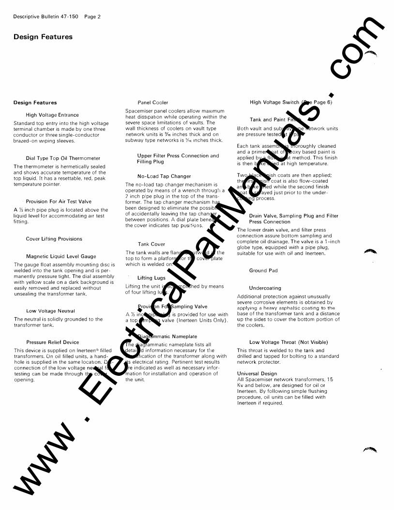
Design Features
High Voltage Entrance
Standard top entry into the high voltage terminal chamber is made by one three conductor or three single-conductor brazed-on Wiping sleeves.
Dial Type Top Oil Thermometer
The thermometer is hermetically sealed and shows accurate temperature of the top liquid. It has a resettable, red, peak tem perature pointer.
Provision For Air Test Valve
A Y, inch pipe plug is located above the liquid level for accommodating air test fitting.
Cover Lifting Provisions
Magnetic Liquid Level Gauge
The gauge float assembly mounting disc is welded into the tank opening and is permanently pressure tight. The dial assembly with yellow scale on a dark background is easily removed and replaced without unsealing the transformer tank.
Low Voltage Neutral The neutral is solidly grounded to the transformer tank,
Pressure Relief Device
This device is supplied on Inerteen® filled transformers. On oil filled units, a handhole is supplied in the same location. DIsconnection of the low voltage neutral for testing can be made through the cover opening.
Panel Cooler
Spacemiser panel coolers allow maximum heat diSSipation while operating within the severe space limitations of vaults. The wall thickness of coolers on vault type network units is 0/,6 inches thick and on subway type networks is 5;;6 Inches thick.
Upper Filter Press Connection and Filling Plug
No-Load Tap Changer
The no-load tap changer mechanism is operated by means of a wrench through a 2 inch pipe plug in the top of the transformer. The tap changer mechanism has been designed to eliminate the possibility of accidentally leaving the tap changer between positions. A dial beneath the cover indicates tap
Tank Cover
The tank walls are flanged outward at the top to form a platform for the cover plate which is welded on.
Lifting Lugs
Lifting the unit is accomplished by means of four lifting lugs.
Provision For Sampling Valve
A Y, inch pipe plug is provided for use with a top sampling valve (Inerteen Units Only)
Diagrammatic Nameplate
The diagrammatic nameplate lists all detailed information necessary for the identification of the transformer along with its electrical rating. Pertinent test results are indicated as well as necessary information for installation and operation of the unit.
High Voltage Switch (See Page 6)
Tank and Paint Finish
Both vault and subway type network units are pressure tested at 8 psi.
Each tank assembly is thoroughly cleaned and a primer coat of epoxy based paint is applied by a flow-coat method. This finish is then bake dried at high temperature.
Two black finish coats are then applied; the first finish coat is also flow-coated and bake dried while the second finish coat is sprayed just prior to the undercoating process.
Drain Valve, Sampling Plug and Filter Press Connection
The lower drain valve, and filter press connection assure bottom sampling and complete oil drainage. The valve is a l-inch globe type, equipped with a pipe plug, suitable for use with oil and Inerteen.
Ground Pad
Undercoating
Additional protection against unusually severe corrosive elements is obtained by applying a heavy asphaltic coati ng to the base of the transformer tank and a distance up the sides to cover the bottom portion of the coolers.
Low Voltage Throat (Not Visible)
This throat is welded to the tank and drilled and tapped for bolting to a standard network protector.
Universal Design All Spacemiser network transformers. 15 Kv and below. are designed for oil or Inerteen. By following simple flushing procedure. oil units can be filled with Inerteen if required.
www . El
ectric
alPar
tMan
uals
. com

Descriptive Bulletin 47-150 Page 3
Design Features
www . El
ectric
alPar
tMan
uals
. com
Descriptive Bulletin 47-150 Page 4
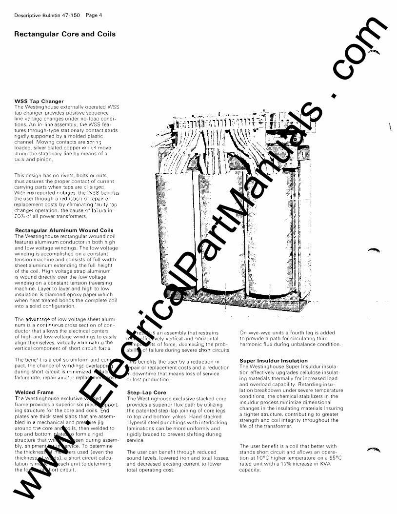
Rectangular Core and Coils
WSS Tap Changer The Westilighouse externally ooerated WSS tap changer provides positive sequence line changes under no�loac condi� tions. An assembly, WSS fea-tures through-type stationary contact studs ngld y supported by a molded plastic channel. Moving contacts are loaded, silver plated copper move
tne stationary Ilile by means of a and pinion.
This desig.'1 has no rivets. bolts or nuts. thus assures the proper contact of current carrying parts when taps are With no reported the the user through a replacement costs by
operation, the cause In all power transformers.
Rectangular Aluminum Wound Coils The Westinghouse rectangular wound coil features aluminum conductor in both high and low voltage windiligs. The low voltage winding is accomplished on a constant tension macr:ine and consists of full width sheet aluminum extending the full height of the coil. High voltage strap aluminum IS wound directly over the low voltage winding on a constant tension traversing machine. Layer to layer and high to low insulation IS diamond epoxy paper which when heat treated bonds the complete coil Into a solid co.'1figuration.
The of low voltage sheet aluml num is a cross section of con-ductor that allows tr:e electrical centers of high and low voltage windings to easily align themselves. virtually the vertical component of short Circuit
The bene"t is a coli so uniform and com� pact, the chance of overlapping during short circuit IS reducing failure rate. repair replar:ement cost.
Welded Frame Westinghouse exclusive welded
frame provides a superior six piece ing structure for the core and coils. plates are thick steel slabs that are assembled in mechanical and pressure Jig around core and coils, then welded to top and bottcm plates to form a rigid structure chat will not loosen during assembly, shipment, or in service. To determine the thickness of :-ne:-nbers used (even the thickness of welds), a short circuit calculation is made for each unit to determine the forces of short ci ICUI!.
The result IS an assembly that restrains more effectively vertical and 'wrizontal components of force, the prob-ability of failure durin�l severe circuits.
This benefits the user by a reduction in repair or replacement costs and a reduction in downtime that means loss of service or los: production.
Step-Lap Core The Westinghouse exclusive stacked core provides a superior flux path by utilizing the patented step-lap Joining of core legs to top and bottom yokes Hand stacked Hypersil steel punchings with interlockin�j laminations can be more uniformly and rigidly braced to prevent shifting dUring service.
The user can benefit through reduced sound levels. lowered iron and total losses. and decreased exciting current to lower total operating cost.
On wye-wye urllts a fourth leg is added to prOVide a path for circulating third harmonic flux dUring unbalance condition.
Super Insuldur Insulation The Westinghouse Super Insuldur insula� lion effectively upgrades cellulose insulating matenals thermally for rncreased load and overload capability. Retarding insulation breakdown under severe temperature conditions, the chem!cal stabilizers In the Insuldur process minimize dimensional changes in the insulating materials insuri.'1g a tighter structure, contributing to greater strength and coil integrity throughout the life of the transformer.
The user benefit is a coil that better with stands short circuit and allows an operation at 10°C higher temperature on a 55°C rated ullit with a 1 2% increase In KVA capacity.
\
www . El
ectric
alPar
tMan
uals
. com

Rectangular Aluminum Wound Coils
Welded Frame Construction
Super
Insuldur
Insulation
Descriptive Bulletin 47-150 Page 5
Rectangular Core and Coils
WSS Tap Changer
www . El
ectric
alPar
tMan
uals
. com

Descriptive Bulletin 47-150 Page 6
Bushings and Terminal Chamber
Bushings Low Voltage Type RFW Standard on network transformers is the low voltage rolled flange welded RFW bushing. This completely sealed hermetic bushing utilizes rolled flange construction for attaching the hardware to the porcelain.
The hardware is inert-arc welded to the tank and stud. The result is a very high strength jOint but with resilient mounting so that mechanical shock is not transmitted to the porcelain. The porcelain of the RFW bushing is externally removable without untanking the transformer.
High Voltage Switch and Terminal Chamber The primary switch is of the rotary type. The three operating pOSitions, indicated by the position of the external switch handle, are: open, closed and ground. No sequence-enforcing device is necessary because the sequence is inherent in the design.
The switch is designed so that when it is moved from open to ground or frorn ground to open the operator must pause in the closed position until he disengages a mechanical stop. This pause allows time for an electrical Interlock to engage, if the transformer is energized, and prevent further movement of the switch.
In any position, the switch handle is held against accidental movement by a springloaded latch which must be released by the operator before he can change pOSItions. This latch also makes it possible to padlock the switch in any position.
The use of one-piece rotary Insulating drum With sliding contacts babbitted accurately mto place eliminates alignment problems. A stainless steel operati ng shaft With a spring-loaded silicone rubber packing gland assembly eliminates the leakage problems in thiS area.
High conductivity copper in blades and contacts will carry 400 amperes continuously without exceeding a 55C temperature rise. In the ground pOSition the switch will withstand 15000 amperes for five seconds without damage.
The SWitch chamber IS furnished with a filling plug, magnetic liqUid level gauge, and comblOation drain valve and sampling plug.
The standard switch assembly is welded to the transformer tank with termlOai chamber compartment located above switch compartment on Spacemiser network transformers.
www . El
ectric
alPar
tMan
uals
. com
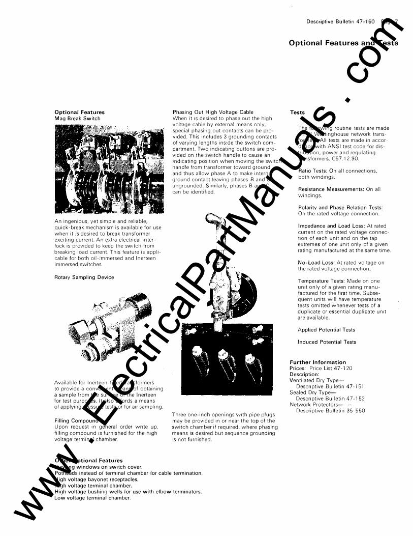
Optional Features Mag Break Switch
An ingenious, yet simple and reliable, quick-break mechanism is available for use when it is desired to break transformer exciting current. An extra electrical inter, lock is prOVided to keep the SWitch from breaking load current This feature is applicable for both oil-immersed and Inerteen immersed switches,
Rotary Sampling Device
Available for Inerleen-filled transformers to provide a convenient means of obtaining a sample from the surface of the Inerteen for test purposes, It also affords a means of applying pressure tests or for air sampling,
Filling Compound Upon request in general order wnte up, filling compound IS furnished for the hiQh voltage terminal chamber.
Other Optional Features Viewing windows on switch cover.
Phasing Out High Voltage Cable When it IS desired to phase out the high voltage cable by external means o.'lly, special phasing out contacts can be provided, ThiS includes 3 grounding contacts of varying lengths ins:de the switch compartment. Two indicating buttons are provided on the SWitch handle to cause an indicating position when moving the switch handle from transformer toward ground and thus allow phase A to make internal ground contact leaving phases B and C ungrounded, Similarly, phases B and C can be identified,
Three one-inch openings With pipe plugs may be provided In or near the top of the switch chamber if required, where phasing means is desired but sequence grounding is not furnished,
Potheads instead of terminal chamber for cable termination, High voltage bayonet receptacles, High voltage terminal chamber. High voltage bushing wells for use with elbow terminators, Low voltage terminal chamber.
Descriptive Bulletin 47-150 Page 7
Optional Features and Tests
Tests
The following routine tests are made on all Westinghouse network transformers. All tests are made in accor �
dance with ANSI test code for distribution. power and regulating transformers, C57,12.90.
Ratio Tests: On all connections, both windlllgs,
Resistance Measurements: On all windlllgs,
Polarity and Phase Relation Tests: On the rated voltage connection,
Impedance and Load Loss: At rated current on the rated voltage connec� tlon of each unit and on the tap extremes of one unit only of a given rating manufactured at the same time.
No-Load Loss: At rated voltage on the rated voltage con nection,
Temperature Tests: Made on one unit only of a given ratlllg manufactured for the first time, Subsequent units will have temperature tests omitted whenever tests of a duplicate or essential duplicate unit are available.
Applied Potential Tests
Induced Potential Tests
Further Information Prices: Price list 47- 120 Description: Ventilated Dry Type
Descflptive Bulletin 47-151 Sealed Dry Type-
Descflptive Bulletin 47-152 Network Protectors- -
Descriptive Bulletin 35-550
www . El
ectric
alPar
tMan
uals
. com
Descriptive Bulletin 47-150 Page 8
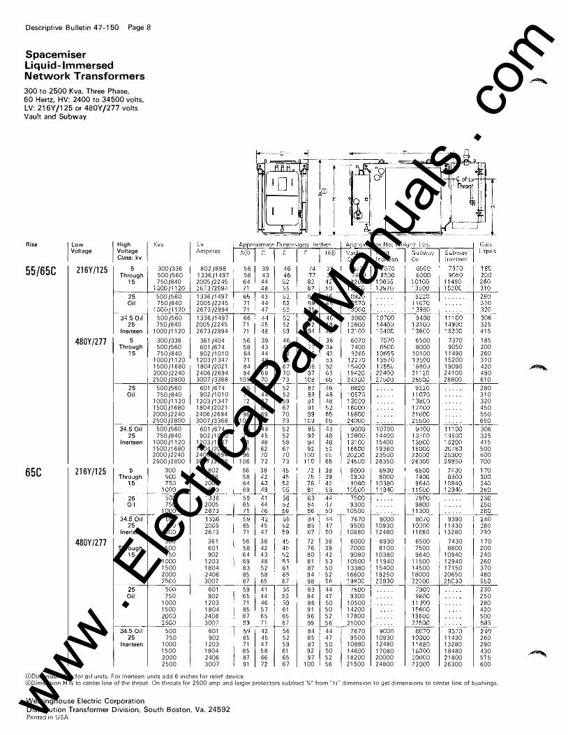
Spacemiser Liquid-Immersed Network Transformers
300 to 2500 Kva, Three Phase, 60 Hertz. HV: 2400 to 34500 volts. LV: 216Y /125 or 480Y /277 volts Vault and Subway
Rise I low Voltage
55/65C 216Y/125 I High I Voltage
Class: kv
5 Through
15
Kva I ��peres
300/336 I 802/898 i 56 1 39 500/560 ' 1336/1497. 58 43 750/840 I 2605/22iU-5 64 , 44
1 ___ -+....:1 000/1� !3/2994 2.1+� !--=,.-+--,::':""'j-.,:c=...._+-. ::..":.:..::-+-:..::c:::.:..-. .. ,,-+...:.,==:,-,-+:..::,:=-,,-+-::.:..::'--.. 25 500/560 1336/1497 , 65 I 43
65C
Oil 750/840 2005/2245 i 71 i 44
-34-.50�"" 500/560 1336/1497 66 ' 100011120 2673/2994 ' 71 I 47
480Yj277 I
216Yj125
25 750/840 2005/2245 71 I Inerteen 1000/1120 2673/2994 71 5 300/336 361/404
Through 500/560 601 /674 15 7501840 90211010
25 Oil
34.5 Oil 25
Inerteen
1000/1120 1203/1347 150011680 180412021
! 200012240 240612694 2500/2800 300713368
500/560 6011674 7501840 902/1010
1000/1120 1203/1347 1500/1680 1804/2021 2000/2240 240612694 2500/2800 3007/3368
500/560 6011674 750/840 90211010
1000/1120 120311347 150011680 180412021 200012240 2406/2694 250012800 3007/3368
56 58 64 71 84 94
101 65 71 72 86 96
106 65 71 71 86 96
106
39 43 44 48 59 68 70 43 44 47 61 69 71 44 45 48 62 70 72
325 415
46 6070 6500 7370 185 46 7400 8000 9050 200 52 10100 11490 260 55 15200 310 67 19090 420 70 24100 490 73 28800 610 52 280 52 310 59 320 67 450 70 550 73 650 52 10700 306 52 14400 325 59 15400 415 67 19360 500 70 23500 600 73 28350 700
Thr���h,
1
�gg 199� �; I :� �'"'! I 300 802 56 : 38
25 �-�
50�
0�-+--"·
1":'=c�' -"�
59 4�1
-+·�·�·+-�":-+:"::':�r �=::'��:'��--+-" �"::"::-·" ��=��'���-
480Y/217
Oil , 750 2005 65 44 1- 34.50i1ni 1 ��� �� :�
25 750 65 45 Inerteen 1000 2673 71 47
5 300 361 56 38 Through 500 601 58 42
15 750 902 64 43 I 1000 1203 69 48 1500 1804 83 52 2000 2406 85 58 2500 3007 87 65
---:2:-::5'-
-+ �-5::-0:-:0:--
--+- 601 59 41 Oil 750 902 65 44
r:4.50il 25
Inerleen
1000 1203 71 46 1500 1804 85 57 I 61
-�-�-g-g - .. �6g�
87
�� "n' ��
500 601 42 56 750 902 65 45 52
1000 1203 71 47 59 1500 1804 85 58 61 2000 2406 87 66 65 2500 3007 91 72 67
<DDimension A is for oil units. For Inerteen units add 6 inches for relief device.
9300 , 9aOO 1050�, 11300
7670 9000 '-a-0
-7n' 9390
9500 10930 10000 11430 10880 12480 11680 13280
72 38 6000 I 6930 6500 I 7430 170 76 39 7000 8100 7500 8600 200 80 42 9080 10380 9640 10940 240 81 53 10500 , 11940 11500 , 12940 i 260 87 50 13380 I 15400 14500 I 17150 370 94 ! 52 16600 , 19250 18000 · 20650 480 98 _5:-c6�t-'1-=9cc8,�.c.2=.28,-3,-0�+-=::-�:
,_t-'2...c.5-,-03,,-0,--+--:5...::5.c.0_ 83 44 75�� I ... . . 230 84 47 9300 , . . . . . 250 86 50 10500 I 280 91 50 14200 · 420 96 52 17800 500 99 56 21 000 +:c_,:.,.�t-'===----1i-':'�':':"".-+''''::''::'''''''-84 44 7670 85 47 9500 10930 87 50 10880 12480 92 50 14600 17080 97 52 18200 20000
100 56 21500 24800
11430 13280 18480 21800 26300
260 290 430 515 600
<DDimension H is to center line of the throat On throats for 2500 amp and larger protectors subtract %" from "'H'· dimenslon to get dimensions to center line of bushings.
Westinghouse Electric Corporation Distribution Transformer Division, South Boston, Va. 24592 Pri nted in liSA www .
Elec
tricalP
artM
anua
ls . c
om