overview of flow around airfoil cfd process workbench geometry physics mesh solution results
TRANSCRIPT

CFD Pre-Lab 2
Simulation of TurbulentFlow
around an Airfoil
Seong Mo Yeon, and Timur Dogan
11/12/2013

Overview of Flow Around Airfoil CFD Process Workbench Geometry Physics Mesh Solution Results
Outline

Simulation of flow around airfoil will be conducted for this lab
Computational fluid dynamics (CFD) results for drag and lift coefficients, coefficient of pressure around the airfoil will be compared to experimental fluid dynamics (EFD)
This lab will cover concept of boundary layer and flow separation
Overview of Flow Around Airfoil
Flow visualization around airfoil(starts at 5:34)

Boundary Layer◦ Defined by Ludwig Prandtl◦ Generated by viscosity near wall◦ Cause of lift and drag forces◦ Inviscid vs. viscous flow◦ Flow separation
Note: Refer to Chapter 9 of your book for more details
Overview of Flow Around Airfoil
Flow visualization of boundary layer(Start at 3:21)

The overall procedure for simulation of flow around airfoil is shown on chart below
Although we will be making the mesh before we define the physics you have to know the physics to design appropriate mesh.
CFD Process
Geometry Physics Mesh Solution Results
Airfoil (ANSYS Design Modeler)
Structured (ANSYS Mesh)
Non-uniform (ANSYS Mesh)
General (ANSYS Fluent - Setup)
Model (ANSYS Fluent - Setup)
Boundary Conditions (ANSYS
Fluent -Setup)
Reference Values (ANSYS Fluent -
Setup)
Turbulent
Solution Methods (ANSYS Fluent -
Solution)
Monitors (ANSYS Fluent - Solution)
Solution Initialization
(ANSYS Fluent -Solution)
Plots (ANSYS Fluent- Results)
Graphics and Animations (ANSYS
Fluent- Results)
C-Domain (ANSYS Design Modeler)
O-Domain (ANSYS Design Modeler)
Solution Initialization
(ANSYS Fluent - Solution)
Solution Controls (ANSYS Fluent -
Solution)
Run Calculation(ANSYS Fluent -
Solution)
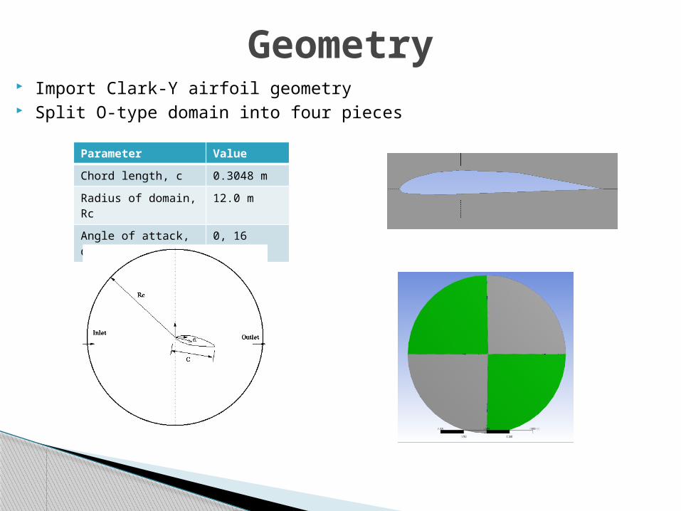
Geometry
Parameter Value
Chord length, c 0.3048 m
Radius of domain, Rc
12.0 m
Angle of attack, α 0, 16
Import Clark-Y airfoil geometry Split O-type domain into four pieces

Inviscid and viscous models Air properties based on experimental temperature measurements Boundary Conditions (BC)
◦ No-slip: velocities are zero (), pressure gradient () is zero◦ Inlet velocity: extracted from experimental data◦ Outlet: (gauge) pressure is imposed to the boundary ()
Inlet – Velocity inlet BC
Outlet – Pressure outlet BC
Wall – No slip BCPhysics
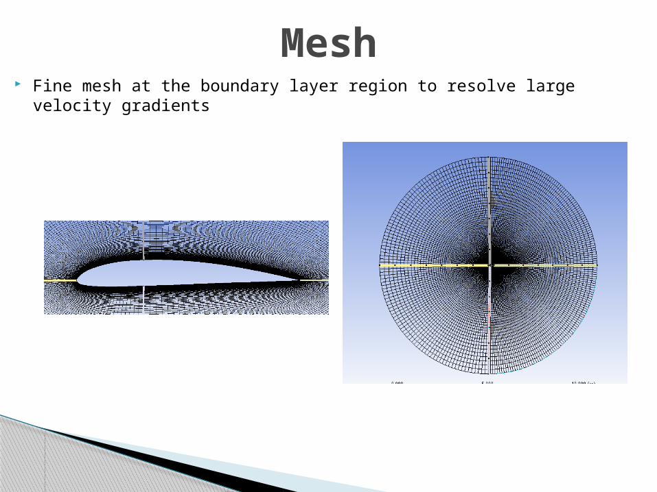
Mesh Fine mesh at the boundary layer region to resolve large velocity gradients

If you have problems with solution convergence reduce Under-Relaxation Factors. This issue is more likely to occur for large angle of attack cases.
Also you may need to increase the number of iterations
Solution

Results
0 4 8 12 16 20
0.000
0.200
0.400
0.600
0.800
1.000
1.200
Coefficent of Lift (Cl) Distribution
Benchmark Data
Pressure Distribution Measurement
Load Cell Measurement
CFD
AoA
Cl
0 4 8 12 16 20
0.000
0.050
0.100
0.150
0.200
0.250
0.300
Coefficent of Drag (Cd) Distribution
Benchmark Data
Wake Velocity Profile Pitot
Load Cell Measurement
Wake Velocity Profile Hot-wire
CFD
AoA
Cd
-20 0 20 40 60 80 100
-2.50000
-2.00000
-1.50000
-1.00000
-0.50000
0.00000
0.50000
1.00000
1.50000
Coefficent of Pressure (Cp ) Distribution at 0 AOA
Benchmark DataExperimental-2013Experimental-2012experimental-2010CFD
X/Chord
Cp -20 0 20 40 60 80 100
-2.500000
-2.000000
-1.500000
-1.000000
-0.500000
0.000000
0.500000
1.000000
1.500000
Coefficent of Pressure (Cp ) Distribution at 16 AOA
Benchmark Data
Experimental-2013
X/Chord
Cp

Pressure distribution around airfoil Velocity vectors near wall and
boundary layer development Stream lines around airfoil
Results