· web viewthe manufacturer shall have a product testing program, including determination of...
TRANSCRIPT

SECTION 11 60 01BROADCAST, THEATER AND STAGE EQUIPMENT
Display hidden notes to specifier. (Don't know how? Click Here)
Copyright 2017 - 2018 ARCAT, Inc. - All rights reserved
PART 1 GENERAL
1.1 SECTION INCLUDES
A. Sound-control doors including the following:1. Integrated sound control door assemblies.
B. Acoustic room components including the following:1. Sound-absorbing and sound-diffusing panels.2. Tunable wall panels.3. Motorized acoustical banners.
C. Theater and stage equipment including the following:1. Acoustical clouds.2. Acoustical shells, DIVA.3. Acoustical shells, Maestro.4. Orchestra pit fillers.5. Stage platforms.6. Tiered audience seating platforms.
D. Specialty casework including the following:1. Musical instrument storage casework.2. Music library system.3. Fixed theater make-up stations.4. Portable theater make-up stations.5. Metal shelving systems.
E. Audience seating including the following:1. Fixed seating - Boston Series.2. Fixed seating - Chicago Series.3. Fixed seating - Madrid Series.4. Fixed seating - Milan Series.5. Fixed seating - Naples Series.6. Fixed seating - New York Series.7. Fixed seating - Sydney Series.
F. Special purpose rooms including the following:1. Modular sound-isolation practice rooms.
G. Mobile performance systems including the following:1. Mobile stage and performance system.
H. Curtains and Rigging Systems:1. Fire curtain systems, brail fire curtain.2. Fire curtain systems, straight lift curtain, proscenium opening up to 18'T x 34'W.3. Fire curtain systems, straight lift curtain, proscenium opening up to 22'T x 42'W.
11 60 01-1

4. Fire curtain systems, straight lift curtain, proscenium opening up to 30'T x 50'W.5. Fire curtain systems, straight lift curtain, proscenium opening greater than 30'T x
50'W.6. Fire curtain systems, curtain accessories.7. Counterweight rigging.8. Helios hoist.9. PowerLift hoist.10. Varion hoist.11. Titan hoist.12. PowerAssist hoist.13. PowerLine hoist.14. Self-Climbing hoist.15. Performer hoist.16. Custom line shaft hoist.17. Drum hoist.18. Pile-up drum hoist.19. Motorized rigging accessories.20. Motorized rigging, control system.21. Stage curtains and tracks.22. Rope and dead hung rigging.
1.2 RELATED SECTIONS
A. Section 01 35 00 - Special Procedures.
B. Section 05 12 00 - Structural Steel Framing.
C. Section 05 50 00 - Metal Fabrications.
D. Section 05 50 00 - Metal Fabrications.
E. Section 06 10 00 - Rough Carpentry.
F. Section 08 11 13.16 - Custom Hollow Metal Doors and Frames.
G. Section 08 71 53 - Security Door Hardware.
H. Section 09 22 16.13 - Non-Structural Metal Stud Framing.
I. Section 09 21 16.23 - Gypsum Board Shaft Wall Assemblies.
J. Section 09 65 13 - Resilient Base and Accessories.
K. Section 12 32 16 - Manufactured Plastic-Laminate-Clad Casework.
L. Section 13 21 48 - Sound-Conditioned Rooms.
M. Division 26 - Electrical for power wiring.
1.3 REFERENCES
A. American Concrete Institute (ACI):1. ACI 117 - Standard Specification for Tolerances for Concrete Construction and
Materials.
B. American Hardboard Association (AHA):1. AHA A135.4-95: Basic Hardboard.
11 60 01-2

C. American Laminators Association (ALA):1. ALA GP 28.
D. American National Standards Institute (ANSI):1. ANSI 115.1: Specifications for Steel Door and Frame Preparation for Hardware.2. ANSI A208.1 - Particleboard.3. ANSI A208.2 - Medium Density Fiberboard.4. ANSI A250.10: Test Procedure and Acceptance Criteria for Prime Painted Steel
Surfaces for Steel Doors and Frames.5. ANSI B17.1 - Keys and Key seats.6. ANSI B18.2.1 - Square, Hex, Heavy Hex, and Askew Head Bolts and Hex, Heavy
Hex, Hex Flange, Lobed Head, and Lag Screws.7. ANSI B18.2.2 - Nuts for General Application: Machine Screw Nuts, Hex, Square, Hex
Flange, and Coupling Nuts.8. ANSI E1.4 - Entertainment Technology - Manual Counterweight Rigging Systems.9. ANSI E1.6-1 - Entertainment Technology - Powered Hoist Systems.10. ANSI E1.22 - Entertainment Technology - Fire Safety Curtain Systems.11. ANSI-BHMA A156.9 - Cabinet Hardware.12. ANSI/BIFMA X5.1 2011 - Office Furnishings - General-Purpose Office.13. ANSI/BIFMA X5.4-2012 - Office Furnishings - Lounge Seating.
E. American Plywood Association (APA).1. Performance Standards and Policies for Structural Use Panels.
F. American Society of Civil Engineers (ASCE):1. ASCE 7 - Minimum Design Loads for Buildings and Other Structures.
G. Architectural Woodwork Institute (AWI):1. Quality Manual, 8th Edition.
H. ASTM International (ASTM):1. ASTM A 36/A 36M - Standard Specification for Carbon Structural Steel.2. ASTM A48 - Standard Specification for Gray Iron Castings.3. ASTM A153 - Standard Specification for Pipe, Steel, Black and Hot-Dipped, Zinc-
Coated, Welded and Seamless.4. ASTM A 500 -Standard Specification for Cold-Formed Welded and Seamless Carbon
Steel Structural Tubing in Rounds and Shapes.5. ASTM A501 - Standard Specification for Hot-Formed Welded and Seamless Carbon
Steel Structural Tubing.6. ASTM A510 - Standard Specification for General Requirements for Wire Rods and
Coarse Round Wire, Carbon Steel, and Alloy Steel.7. ASTM A513 - Standard Specification for Electric-Resistance-Welded Carbon and
Alloy Steel Mechanical Tubing.8. ASTM A1008/A 1008M - Standard Specification for Steel, Sheet, Cold-Rolled,
Carbon, Structural, High-Strength Low-Alloy, High-Strength Low-Alloy with Improved Formability, Solution Hardened, and Bake Hardenable.
9. ASTM A1011 - Standard Specification for Steel, Sheet and Strip, Hot Rolled, Carbon, Structural, High-Strength Low Alloy, High-Strength Low Alloy With Improved Formability, and Ultra High Strength.
10. ASTM B85 - Standard Specification for Aluminum Alloy Die Castings.11. ASTM B209 - Specification for Aluminum and Aluminum-Alloy Sheet and Plate.12. ASTM B221 - Specification for Aluminum and Aluminum-Alloy Extruded Bars, Rods,
Wire, Profiles, and Tubes.13. ASTM B429 - Specification for Aluminum-Alloy Extruded Structural Pipe and Tube.14. ASTM C423 - Standard Test Method for Sound Absorption and Sound Absorption
Coefficients by the Reverberation Room Method.
11 60 01-3

15. ASTM C510 - Standard Specification for General Requirements for Steel Rods and Coarse Round Wire, Carbon Steel.
16. ASTM C503 - Specification for Silvered Flat Glass Mirror.17. ASTM E84 - Standard Test Method for Surface Burning Characteristics of Building
Materials.18. ASTM E90 - Standard Test Method for Laboratory Measurement of Airborne Sound
Transmission Loss of Building Partitions and Elements.19. ASTM E 413 - Classification for Rating Sound Transmission.20. ASTM E488 - Standard Test Methods for Strength of Anchors in Concrete and
Masonry Elements.21. ASTM E795 - Practices for Mounting Test Specimens during Sound Absorption Tests.22. ASTM F851: Test Method for Self-Rising Seat Mechanisms.
I. Audio Engineering Society (AES): AES-4id - AES information document for room acoustics and sound reinforcement systems -- Characterization and measurement of surface scattering uniformity.
J. Builders Hardware Manufacturers Association (BHMA): ANSI/BHMA A156.9 - Cabinet Hardware.
K. California, Department of Consumers Affairs, Bureau of Home Furnishings and Thermal Insulation:1. California Technical Bulletin 117 - requirements, Test Procedures and Apparatus for
Testing Flame Retardance of Resilient Filling Materials Used in Upholstered Furniture.2. California Technical Bulletin 133 - Flammability Test Procedure for Seating Furniture
for Use in Public Occupancies.
L. Canadian Electrical Code (CDC).
M. Code of Federal Regulations (CFR):1. 16 CFR 1201 - Safety Standard for Architectural Glazing Materials.2. 16 CFR 1610.61 - Clarification of Flammability Standard for Clothing Textiles (CS
191-53).
N. GREENGUARD Environmental Institute (GEI): GREENGUARD certified low emitting products.
O. Hardwood Plywood and Veneer Association (HPVA): HPVA HP-1 - Hardwood and Decorative Plywood.
P. International Organization for Standardization (ISO): ISO 9001 Quality management systems - Requirements.
Q. International Building Code (IBC).
R. Laminating Materials Association:1. LMA EDG-1: Voluntary Product Standard and Typical Physical Properties of
Edgebanding Materials.2. LMA SAT-1: Voluntary Product Standard and Typical Physical Properties of Saturated
Paper Overlays.
S. National Association of Architectural Metal Manufacturers (NAAMM): Metal Finishes Manual for Architectural and Metal Products.
T. National Electrical Code (NEC).
U. National Electrical Manufacturers Association (NEMA): NEMA LD 3-2000 - High Pressure Decorative Laminates.
11 60 01-4

V. National Fire Protection Association (NFPA): NFPA 80 - Standard For Fire Doors and Other Opening Protectives.
W. Underwriter's Laboratory (UL):1. UL 10C - Standard for Positive Pressure Fire Tests of Door Assemblies.2. UL 723 - Test For Surface Burning Characteristics of Building Materials.3. UL 1480, UL 2043 - Fire Test for Heat and Visible Smoke Release for Discrete
Product and Their Accessories Installed in Air-Heating Spaces.
X. U.S. Architectural & Transportation Barriers Compliance Board: Americans with Disabilities Act (ADA) and Architectural Barriers Act (ABA) Accessibility Guidelines for Buildings and Facilities.
Y. U.S. Department of Commerce, National Institute of Standards and Technology: DOC PS 1: U.S. Product Standard for Construction and Industrial Plywood.
Z. US Green Building Council (USGBC): Leadership in Energy and Environmental Design (LEED).
1.4 SUBMITTALS
A. Submit under provisions of Section 01 30 00 - Administrative Requirements.
B. Product Data: Manufacturer's data sheets on each product to be used, including:1. Provide test results by certified independent testing laboratory indicating compliance
with performance requirements.2. Rated capacities, construction details, material descriptions, dimensions of individual
components, profiles, and finishes.3. Delivery, storage, handling, and installation instructions and recommendations.4. Maintenance instructions and recommendations.
C. LEED Submittals:1. Manufacturer's certificate indicating that composite wood products and adhesives
contain no added urea formaldehyde.2. Manufacturer's certificate indicating percentages by weight of post-consumer and pre-
consumer recycled content. Include statement indicating costs for each product having recycled content.
3. Credit EQ 4.4: Manufacturer's Signed Confirmation indicating that composite wood products and adhesives used in acoustical shells contain no urea formaldehyde.
D. Shop Drawings:1. Submit component and project specific installation drawings, cut sheets, and
schedules showing all information necessary to fully explain the design features, appearance, function, fabrication, installation, and use of system components in all phases of operation. Submit for approval before beginning any fabrication, installation, or erection.
2. A copy of the Bill of Material shall be included with the submission for approval.3. Include fabrication and installation details. Distinguish between factory and field work.4. Include plans, elevations, sections, attachments and work by other trades.5. Include wiring diagrams when applicable.6. Indicate seismic bracing and fastening requirements as applicable.
E. Coordination Drawings: Project-specific Coordination Drawings, indicating the following items drawn and coordinated with each other. Include information required by Installers of each item in order to coordinate the Work. Include the following:1. Relationship of items shown on separate Shop Drawings.2. Dimensions and required clearances of adjacent or related work.
11 60 01-5

3. Order of assembly of separate items.4. Information required for interface with other trades and components, including
mechanical, electrical, and communication work.
F. Product Schedule:1. Use designations indicated on the Drawings.2. Include room locations, dimensions, accessories, finishes, and project specific notes.
G. Verification Samples:1. Exposed Finishes and Finish Materials: Not less than 4 by 4 inches (102 by 102 mm),
for each type, color, pattern, surface and material selected.2. Curtain Materials: Not less than 12 by 12 inches (305 by 305 mm).
H. Closeout Submittals:1. Operation and Maintenance Data: For adjusting, repairing and replacing components
and accessories.2. Warranty: Submit manufacturer's warranty.
I. Field Quality Control Reports: Documenting inspections and demonstrations of installed products and equipment.
1.5 QUALITY ASSURANCE
A. Source Limitations: Obtain all products from a single manufacturer through one source providing a comprehensive material and installation package:
B. Manufacturer Qualifications: Minimum 5 years' experience in manufacture of similar products in use in similar environments, including project size, and complexity, and with the production capacity to meet the construction and installation schedule.
C. Installer Qualifications: Experienced in installation of the work of this section and acceptable to the manufacturer.
D. Electrical Components: Listed and labeled per NFPA 70, Article 100 by a testing agency acceptable to authorities having jurisdiction.
E. Testing of Seats: All qualifying seats must have been independently tested and passed ANSI/BIFMA X5.4-2012 standards for Office Furnishings - Lounge Seating.1. Seating Durability: A load of 125 pounds shall be applied to the seat. The chair shall
be tested to 10,000 cycles.2. Backrest Durability Horizontal: A load of 75 pounds shall be applied to the backrest.
The chair shall be tested to 10,000 cycles.3. Backrest Durability Vertical: A load of 200 pounds shall be applied to the backrest.
The chair shall be tested to 10,000 cycles.4. Arm Durability Vertical: A load of 150 pounds shall be applied to the armrest structure.
The chair shall be tested to 10,000 cycles.5. Arm Durability Horizontal: A load of 100 pounds shall be applied to the armrest
structure. The chair shall be tested to 10,000 cycles.6. Drop Test: Release 300 pounds test bag one time from a height of 6 inches above
uncompressed seat surface.7. Load Test: Seat must hold 600 pounds load for 30 minutes without damage to the
seat.
F. Regulatory Requirements: Where components are indicated to comply with accessibility requirements, comply with the U.S. Architectural & Transportation Barriers Compliance Board's "Americans with Disabilities Act (ADA) and Architectural Barriers Act (ABA) Accessibility Guidelines for Buildings and Facilities".
11 60 01-6

G. Curtain and Rigging Systems, Manufacturer Qualifications: Minimum 5 years experience in manufacture of similar products in use in similar environments, including project size, and complexity, and with the production capacity to meet the construction and installation schedule.1. Theatrical rigging systems are specialized overhead lifting systems. Due to the highly
specialized nature of theatrical rigging equipment, and the safety requirements of the equipment, the rigging products provided for this work shall be the products of a single rigging manufacturer for quality, consistency and ease of integration. Accessory items such as wire rope, fittings, and curtain tracks may be from other specialty manufacturers.
2. The rigging manufacturer shall have the following programs in place.a. The manufacturer shall have a product testing program, including determination
of recommended working loads for products based on destructive testing and review by a licensed engineer.
b. The manufacturer of the performance equipment shall have a quality management system that is registered to the ISO 9001standard.
c. The manufacturer shall carry primary product and general liability insurance of $2,000,000 each, with excess liability coverage of $10,000,000 and a Contractors Professional Liability policy with $2,000,000 coverage.
H. Rigging Systems, Installer Qualifications: Manufacturer's authorized representative, trained and approved for installation of units required for this Project.1. The Rigging Contractor shall be an approved rigging manufacturer or an authorized
representative or dealer of an approved manufacturer. The contractor shall have been installing stage rigging systems for a period of five years or more, and shall have completed at least ten installations of this type and scope. The AHJ shall be the final judge of the suitability of experience.
2. The Rigging Contractor shall employ an Entertainment Technician Certification Program (ETCP) Certified Theatre Rigger. A Certified Rigger shall be either the project manager or site foreman, and be responsible for the overall project including the layout, inspection, and onsite user training.
I. Rigging Systems, Minimum Standards of Safety, the following factors shall be used:1. Cables & Fittings: 8:1 Safety Factor.2. Cable D/d ratio: Sheave tread diameter is the minimum D/d ratio per the "Wire Rope
User Manual" or recommended by the wire rope manufacturer.3. Tread Pressures: 500 lbs. for cast iron, 900 lbs. for Nylatron, 1000 lbs. for steel.4. Maximum Fleet Angle: 1-1/2 degrees.5. Steel: 1/5 of yield strength or per AISC Specification.6. Bearings: Two times required load at full speed for 2000 hours.7. Bolts: Minimum SAE J429 Grade 5 (ISO R898 Class 8.8), zinc plated.8. Motors: 1.0 AGMA Service Factor.9. Gearboxes: 1.25 Mechanical Strength Service Factor, 1.0 Gearing Service Factor.
J. Mock-Up: Provide a mock-up for evaluation of surface preparation techniques and installation workmanship.1. Finish areas designated by Architect including shims, sealants, and accessories.2. Provide full size units, if accepted, units may remain as part of the completed work.3. Do not proceed with remaining work until workmanship is approved by Architect.4. Refinish mock-up area as required to produce acceptable work.
1.6 DELIVERY, STORAGE, AND HANDLING
A. Deliver materials in manufacturer's original unopened containers with manufacturer's labels attached. Do not deliver material until spaces to receive them are clean, dry, and ready for their installation. Ship to jobsite only after roughing-in, painting and other finishing work has been completed, installation areas are ready to accept work.
11 60 01-7

B. Handle and install materials to avoid damage.
1.7 PROJECT CONDITIONS
A. Environmental Limitations: Do not deliver or install materials until spaces are enclosed and weather tight, wet work in spaces is complete and dry, HVAC system is operating and maintaining ambient temperature at occupancy levels during the remainder of the construction period.
B. Field Measurements: Verify field measurements as indicated on Shop Drawings. Where measurements are not possible, provide control dimensions and templates.1. Coordinate installation and location of blocking and supports as requested.2. Verify openings, clearances, storage requirements and other dimensions relevant to
the installation and final application.3. Where applicable, coordinate locations of electrical junction boxes.
C. Field Measurements: Verify field measurements as indicated on Shop Drawings. Where measurements are not possible, provide control dimensions and templates.1. Coordinate locations of electrical junction boxes.
D. Ensure that products of this section are supplied to affected trades in time to prevent interruption of construction progress.
1.8 WARRANTY
A. Special Warranty for Sound Control Doors: Manufacturer's written warranty indicating manufacturer's intent to repair or replace components of sound-control door assemblies that fail in materials or workmanship within 5 years from date of Substantial Completion. Failures are defined to include, but are not limited to, the following:1. Fracturing or breaking of unit components including doors and hardware resulting
from normal use other than vandalism.2. Warping or deterioration of components not resulting from leaks, flooding, or other
uncontrolled moisture or humidity.3. Failure of acoustical gaskets and seals.
B. Special Warranty for Acoustic Room Components: Manufacturer's written warranty indicating manufacturer's intent to repair or replace panels that fail in materials or workmanship. Failures are defined to include, but are not limited to, the following:1. Fracturing or breaking of unit components which results from normal wear and tear
and normal use other than vandalism.2. Warping of components not resulting from leaks, flooding, or other uncontrolled
moisture or humidity.3. Failure of unit to perform acoustically in accordance with manufacturer's published
data.4. Sound-Absorbing and Sound-Diffusing Panels Warranty Period: 5 years.5. Tunable Wall Panels Warranty Period: 5 years.6. Motorized Acoustical Banners Warranty Period: 3 years.
C. Special Warranty for Specialty Casework: Manufacturer's written warranty indicating manufacturer's intent to repair or replace components of specialty casework that fail in materials or workmanship within 10 years from date of Substantial Completion. Failures are defined to include, but are not limited to, the following:1. Fracturing or breaking of casework components including doors, panels, shelves, or
hardware resulting from normal wear and tear and normal use other than vandalism.2. Delamination or other failures of glue bond of components.3. Warping of casework components not resulting from leaks, flooding, or other
uncontrolled moisture or humidity.
11 60 01-8

4. Failure of operating hardware.
D. Special Warranty for Fixed Audience Seating: Manufacturer's written warranty indicating manufacturer's intent to repair or replace components of fixed audience seating that fail in materials or workmanship.1. Failures include, but are not limited to, the following:
a. Fracturing or breaking of unit components which results from normal wear and tear and normal use other than vandalism.
b. Delamination or other failures of glue bond of components.c. Warping of components not resulting from leaks, flooding, or other uncontrolled
moisture or humidity.2. Damage from deliberate destruction and vandalism is excluded.3. Warranty Period:
a. Structure (including back bracket, standard, metal base): 10 years.b. Operating mechanisms (including seat/back cushion, wood works (wood
panels/armrest/ADA end arms), plastic parts (plastic shells, polypropylene armrest), tip-up seat mechanism, writing tablet (including writing tablet mechanism): 5 years.
c. Accessories (such numbering, aisle light, moveable base, and similar items): 3 years.
E. Special Warranty for Special Purpose Rooms: Manufacturer's written warranty indicating manufacturer's intent to repair or replace components of sound-isolation practice rooms that fail in materials or workmanship within 5 years from date of Substantial Completion. Failures are defined to include, but are not limited to, the following:1. Fracturing or breaking of room components, including doors, panels, or hardware, that
results from normal wear and tear and normal use other than vandalism.2. Delamination or other failures of glue bond of components.3. Warping of components not resulting from leaks, flooding, or other uncontrolled
moisture or humidity.4. Failure of operating hardware.5. Failure of acoustical gaskets and seals.6. Failure of room to perform acoustically in accordance with manufacturer's published
data.
F. Special Warranty for Curtain Systems: Provide manufacturer's standard limited 3 year warranty against defects in materials or workmanship from the date of Substantial Completion. The warranty is contingent on inspection of the equipment and training of its use being provided annually by an Entertainment Technician Certification Program (ETCP) Certified Theatre Rigger at the Owner's expense. It is the responsibility of the end user to make arrangements for the annual inspection and training. Failure to obtain the inspection and training annually shall result in a one year warranty. The warranty shall not cover equipment that has become defective due to misuse, abuse, accident, act of God, alteration, vandalism, ordinary wear and tear, improper maintenance, or used not in a manner intended.
G. Special Warranty for Mobile Stage Systems (Showmobile): Provide manufacturer's standard limited 5 year warranty from the date of delivery of the product.
H. Special Warranty for Rigging Systems: Provide manufacturer's standard limited 3 year warranty against defects in materials or workmanship from the date of Substantial Completion. The warranty is contingent on inspection of the equipment and training of its use being provided annually by an Entertainment Technician Certification Program (ETCP) Certified Theatre Rigger at the Owner's expense. It is the responsibility of the end user to make arrangements for the annual inspection and training. Failure to obtain the inspection and training annually shall result in a one year warranty. The warranty shall not cover equipment that has become defective due to misuse, abuse, accident, act of God, alteration,
11 60 01-9

vandalism, ordinary wear and tear, improper maintenance, or used not in a manner intended.
1.9 EXTRA MATERIALS/ATTIC STOCK FOR FIXED AUDIENCE SEATING
A. Furnish the following extra materials from the same manufacturing run as the original products that match products installed. Package with protective coating and identified with product labels.1. Full-size units of the following seating components equal to 5 percent of amount
installed for each type and finish installed, but no fewer than two units:a. Arm standards (both center and end standards).b. Wooden/Plastic seat back and cushion covers.c. Seat bottom.d. Lighting Components devices.e. Fabric.
PART 2 PRODUCTS
2.1 MANUFACTURERS
A. Acceptable Manufacturer: Wenger Corporation, JR Clancy and GearBoss, which is located at: 555 Park Dr.; Owatonna, MN 55060 ; Toll Free Tel: 800-4WENGER (493-6437); Tel: (507) 455-4100; Fax: (507) 455-4258; Email:request info ([email protected]); Web:https://www.wengercorp.com|http://www.jrclancy.com
B. Acceptable Manufacturer: Wenger Corporation; JR Clancy , which is located at: 7041 Interstate Island Rd, Syracuse, NY 13209. Tel: (315) 451-3440. www.jrclancy.com.
C. Substitutions: Not permitted.
D. Requests for substitutions shall be considered in accordance with provisions of Section 01 60 00 - Product Requirements.1. Manufacturers seeking approval shall submit the following:
a. Product data, including third-party certified acoustical data and proposed layout for this project.
b. Project references: Minimum of 5 installations not less than 3 years old, with owner contact information.
c. Sample warranty.2. Submit substitution request not less than required days prior to bid date.3. Approval shall be indicated by issuance of written Addendum.4. Approved manufacturers shall meet separate requirements of Submittals Article.
E. Rigging Systems, Requirements for Approval: Other equipment manufacturers seeking approval shall submit the following information at least 2 weeks prior to the bid opening date. Approval of manufacturers shall be by addenda. Failure to submit any of the required information shall automatically disqualify the manufacturers from consideration of approval.1. Evidence that the manufacturer has been in business for a minimum of ten years
manufacturing stage equipment.2. A listing of 10 equivalent installations, including:
a. Name, address and telephone number of owner;.b. Name, address and telephone number of architect;.c. Scope of work.
3. A brief written description of the manufacturer's operation including facilities, financial capabilities, and experience of key personnel.
4. Written, third party evidence showing that the manufacturer has the testing, quality management and insurance programs required above in place.
11 60 01-10

2.2 INTEGRATED SOUND CONTROL DOOR ASSEMBLlES
A. Basis of Design: Sound Control Door Assemblies as manufactured by Wenger Corporation.
B. Performance Requirements: Provide sound-control door assemblies identical to assemblies tested by an independent testing agency per ASTM E 90 with the specified minimum certified STC rating per ASTM E 413 for the configurations indicated.1. Acoustical performance shall meet manufacturer's published data for transmission
loss based on door type specified.
C. Compliance for Fire-Rated Sound-Control Door and Frame Assemblies:1. NFPA 80 compliant, listed and labeled by a testing and inspection agency acceptable
to authorities having jurisdiction.2. Test at equalized pressure per UL 10C.
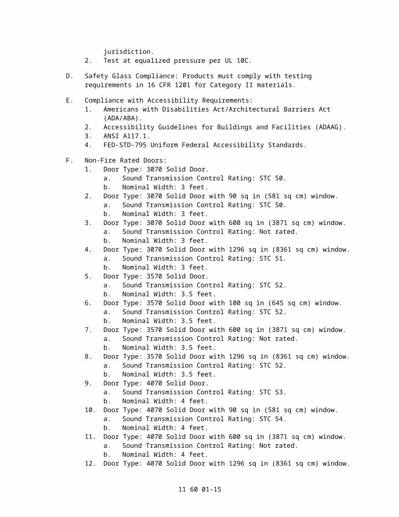
D. Safety Glass Compliance: Products must comply with testing requirements in 16 CFR 1201 for Category II materials.
E. Compliance with Accessibility Requirements:1. Americans with Disabilities Act/Architectural Barriers Act (ADA/ABA).2. Accessibility Guidelines for Buildings and Facilities (ADAAG).3. ANSI A117.1.4. FED-STD-795 Uniform Federal Accessibility Standards.
F. Non-Fire Rated Doors:1. Door Type: 3070 Solid Door.
a. Sound Transmission Control Rating: STC 50.b. Nominal Width: 3 feet.
2. Door Type: 3070 Solid Door with 90 sq in (581 sq cm) window.a. Sound Transmission Control Rating: STC 50.b. Nominal Width: 3 feet.
3. Door Type: 3070 Solid Door with 600 sq in (3871 sq cm) window.a. Sound Transmission Control Rating: Not rated.b. Nominal Width: 3 feet.
4. Door Type: 3070 Solid Door with 1296 sq in (8361 sq cm) window.a. Sound Transmission Control Rating: STC 51.b. Nominal Width: 3 feet.
5. Door Type: 3570 Solid Door.a. Sound Transmission Control Rating: STC 52.b. Nominal Width: 3.5 feet.
6. Door Type: 3570 Solid Door with 100 sq in (645 sq cm) window.a. Sound Transmission Control Rating: STC 52.b. Nominal Width: 3.5 feet.
7. Door Type: 3570 Solid Door with 600 sq in (3871 sq cm) window.a. Sound Transmission Control Rating: Not rated.b. Nominal Width: 3.5 feet.
8. Door Type: 3570 Solid Door with 1296 sq in (8361 sq cm) window.a. Sound Transmission Control Rating: STC 52.b. Nominal Width: 3.5 feet.
9. Door Type: 4070 Solid Door.a. Sound Transmission Control Rating: STC 53.b. Nominal Width: 4 feet.
10. Door Type: 4070 Solid Door with 90 sq in (581 sq cm) window.a. Sound Transmission Control Rating: STC 54.b. Nominal Width: 4 feet.
11. Door Type: 4070 Solid Door with 600 sq in (3871 sq cm) window.a. Sound Transmission Control Rating: Not rated.
11 60 01-11

b. Nominal Width: 4 feet.12. Door Type: 4070 Solid Door with 1296 sq in (8361 sq cm) window.
a. Sound Transmission Control Rating: STC 53.b. Nominal Width: 4 feet.
13. Door Type: 6070 Solid Door.a. Sound Transmission Control Rating: Not rated.b. Nominal Width: 6 feet.
14. Door Type: 6070 Solid Door with 90 sq in (581 sq cm) window.a. Sound Transmission Control Rating: Not rated.b. Nominal Width: 6 feet.
15. Door Type: 6070 Solid Door with 600 sq in (3871 sq cm) window.a. Sound Transmission Control Rating: Not rated.b. Nominal Width: 6 feet.
16. Door Type: 6070 Solid Door with 1296 sq in (8361 sq cm) window.a. Sound Transmission Control Rating: 51.b. Nominal Width: 6 feet.
G. Fire Rated Doors: 1 Hour rating.1. Door Type: 3070 Solid Door.
a. Sound Transmission Control Rating: STC 49.b. Nominal Width: 3 feet.
2. Door Type: 3070 Solid Door with 90 sq in (581 sq cm) window.a. Sound Transmission Control Rating: STC 48.b. Nominal Width: 3 feet.
3. Door Type: 3070 Solid Door with 600 sq in (3871 sq cm) window.a. Sound Transmission Control Rating: Not rated.b. Nominal Width: 3 feet.
4. Door Type: 3570 Solid Door.a. Sound Transmission Control Rating: Not rated.b. Nominal Width: 3.5 feet.
5. Door Type: 3570 Solid Door with 90 sq in (581 sq cm) window.a. Sound Transmission Control Rating: Not rated.b. Nominal Width: 3.5 feet.
6. Door Type: 4070 Solid Door.a. Sound Transmission Control Rating: Not rated.b. Nominal Width: 4 feet.
7. Door Type: 4070 Solid Door with 90 sq in (581 sq cm) window.a. Sound Transmission Control Rating: Not rated.b. Nominal Width: 4 feet.
8. Door Type: 6070 Solid Door.a. Sound Transmission Control Rating: Not rated.b. Nominal Width: 6 feet.
9. Door Type: 6070 Solid Door with 90 sq in (581 sq cm) window.a. Sound Transmission Control Rating: Not rated.b. Nominal Width: 6 feet.
H. Sound-Control Door Assemblies: Provide sound-control door assemblies consisting of acoustically engineered door and frame combination with engineered sound seals.1. Designation in schedule on Drawings: SCD# ___.2. Door Configuration: Single leaf.3. Door Configuration: Double leaf.4. Door Configuration: As scheduled on Drawings.5. Door Leaf Size: 36 inch (91 mm).6. Door Leaf Size: 42 inch (107 mm).7. Door Leaf Size: 48 inch (122 mm).8. Door Leaf Size: As scheduled on Drawings.
11 60 01-12

9. Glazing Lite Size, per Door: None.10. Glazing Lite Size, per Door: 90 sq in (581 sq cm).11. Glazing Lite Size, per Door: 600 sq in (3871 sq cm).12. Glazing Lite Size, per Door: 1296 sq in (8361 sq cm).13. Glazing Lite Size, per Door: As scheduled on Drawings.14. Fire Rating: None.15. Fire Rating: 60 minutes.16. Fire Rating: As scheduled on Drawings.17. Assembly Sound Transmission Class (STC): ___.18. Assembly Sound Transmission Class (STC): Not rated.19. Assembly Sound Transmission Class (STC): As scheduled on Drawings.
I. General: Provide flush-type steel sound-control doors minimum 2-1/2 inch (64 mm) thick, with split, crimped, and gasketed isolation construction with harmonically unbalanced steel face thicknesses and window lite thicknesses. Fabricate without visible seams on exposed faces.1. Door Cores: Manufacturer's standard meeting specified STC rating.2. Door Cores: Manufacturer's standard meeting specified STC and fire rating.3. Door Cores: Manufacturer's standard meeting requirements for STC and fire rating as
scheduled on Drawings.4. Door Face Sheets: 14 gauge/0.067 inch (1.7 mm) and 12 gauge/0.093 inch (2.3 mm)
cold-rolled steel sheet, on opposing faces.
J. Door Hardware Reinforcement: Minimum 14 gauge (0.067 inch) (1.7 mm), hot-rolled or cold-rolled steel sheet as reinforcement for hinges, lock face, flush bolts, closers, and concealed holders.
K. Acoustic Vision Lite Assembly: Metal-framed unit consisting of harmonic vibration-resistant 1/4 inch (6.0 mm) and 3/8 inch (9.0 mm) thick laminated glazing with 2.81 inch (71 mm) interspace.
L. Frame Fabrication:1. Materials: 14 gauge/0.067 inch (1.7 mm) cold-rolled steel sheet.2. Construction: Full-welded unit.3. Corners: Mitered and reinforced.4. Frame Design: Split frame design with integrated frame support for metal threshold.5. Frame Acoustic Liner, Non-Fire-Rated Doors: Factory-installed sound-absorbing
material behind acoustic seal rabbet.
M. Frame Hardware Reinforcement: Minimum 14 gauge/0.067 inch (1.7 mm) reinforcement for hinges, lock face, and closers.
N. Door Hardware: Provide manufacturer's standard acoustical seals, threshold, and hinges required to achieve sound control performance requirements specified.
O. Acoustical Seals:1. Head and Jambs, Non-Fire-Rated Doors: Extruded flexible vinyl with dual magnetic
seals, uninterrupted at hinge and latch.2. Head and Jambs, Fire Rated Doors: Silicone compression seal, uninterrupted at hinge
and latch, with intumescent material in jamb meeting requirements of fire-resistance assembly specified in Quality Assurance Article.
3. Door Bottoms: Fixed in place foam and fiberglass-backed, teflon-coated sweep seal, field-adjustable, providing sound control seal without mechanical drop operation.
P. Hinges: Cam-lift wrap-around continuous barrel-type hinge.
11 60 01-13

Q. Metal Thresholds: Flat, smooth plate stainless steel, 5/16 inch (7.9 mm) high, profiled to provide sound control seal with door bottom seal.
R. Locksets: Provide door manufacturer's standard mortise lockset.
S. Locksets: Provide door with standard mortise pocket prepared to receive mortise lockset specified in another Division 08 section and frame prepared to receive standard strike plate, with door edge and frame cover plates included.
T. Other Door Hardware: Refer to requirements of Section 08 71 53 - Security Door Hardware.
U. Fasteners: Refer to Section 06 10 00 - Rough Carpentry.
V. General Fabrication:1. Fabricate sound-control door assemblies to same tolerances as tested units meeting
performance requirements.2. Form surfaces smooth and flush with invisible joints when doors are closed.3. Factory-assemble doors, frames, manufacturer-provided hardware, and glazed lites.
W. Door Fabrication:1. Form metal doors to required sizes with minimum radius.2. Join door faces at vertical edges by welding or crimping method identical to
manufacturer's tested units.
X. Frame Fabrication:1. Form metal frames to required sizes with minimum radius.2. Weld joints continuously.3. Make joints smooth, flush, and invisible.4. Provide plaster guards where required to contain grout or mortar.
Y. Hardware Preparation: In compliance with ANSI A115.1.1. Factory-prepare assemblies to received hardware.2. Prepare for hardware mounting as recommended by manufacturer in accordance with
manufacturer's acoustically tested assemblies.
Z. Primer: Factory primed for field-applied painted finish.1. Type: Manufacturer's standard, lead- and chromate-free primer.2. Compliance: ANSI A250.10.3. Thickness: Minimum 0.7 mils (0.018 mm) thick.
2.3 SOUND-ABSORBING AND SOUND-DIFFUSING PANELS
A. Basis of Design: Provide a system of acoustical panels, as manufactured by Wenger Corporation, that absorb or diffuse sound in a configuration designed to reduce excess sound energy levels and improve sound distribution throughout the space.
B. Performance Requirements: Provide sound absorbing and sound-diffusing panels meeting requirements with the following characteristics:1. Wall Panel Mounting Types for Acoustical Performance Characteristics according to
ASTM E 795, with measurements determined according to ASTM C 423:a. No air space.
2. Ceiling Diffuser Panel Mounting Types for Acoustical Performance Characteristics according to ASTM E 795, with measurements determined according to ASTM C 423:a. No air space.b. E-150: 6 inches (152 mm) air space.c. E-400: 16 inches (410 mm) air space.
11 60 01-14
C. Wall and Ceiling Absorber Panels: Manufacturer's standard panel, with fabric covering laminated to front face of rigid glass-fiber board, with chemically hardened edges, with the following characteristics:1. Basis of Design Product: Wenger Wall Absorber Panel and Ceiling Absorber Panel.2. Absorber Panel Size: Width and length indicated on the Drawings.
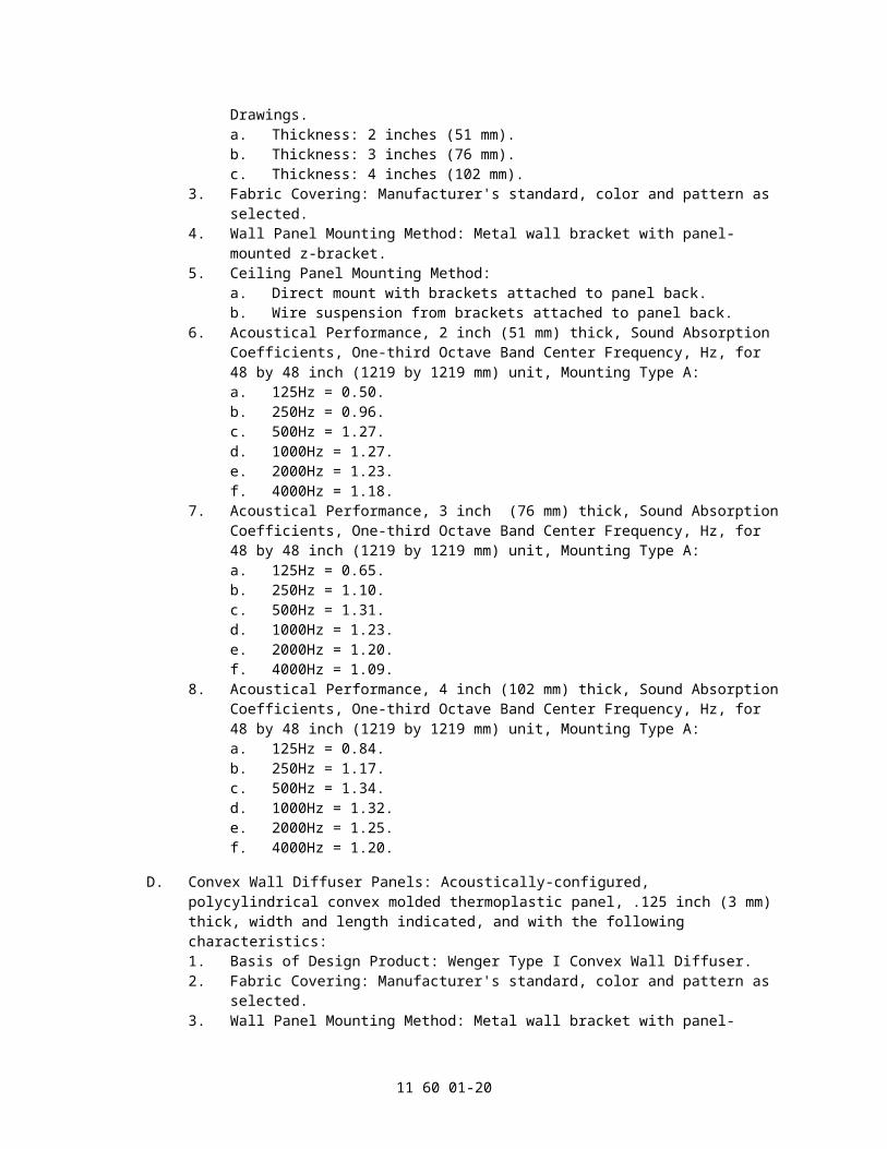
a. Thickness: 2 inches (51 mm).b. Thickness: 3 inches (76 mm).c. Thickness: 4 inches (102 mm).
3. Fabric Covering: Manufacturer's standard, color and pattern as selected.4. Wall Panel Mounting Method: Metal wall bracket with panel-mounted z-bracket.5. Ceiling Panel Mounting Method:
a. Direct mount with brackets attached to panel back.b. Wire suspension from brackets attached to panel back.
6. Acoustical Performance, 2 inch (51 mm) thick, Sound Absorption Coefficients, One-third Octave Band Center Frequency, Hz, for 48 by 48 inch (1219 by 1219 mm) unit, Mounting Type A:a. 125Hz = 0.50.b. 250Hz = 0.96.c. 500Hz = 1.27.d. 1000Hz = 1.27.e. 2000Hz = 1.23.f. 4000Hz = 1.18.
7. Acoustical Performance, 3 inch (76 mm) thick, Sound Absorption Coefficients, One-third Octave Band Center Frequency, Hz, for 48 by 48 inch (1219 by 1219 mm) unit, Mounting Type A:a. 125Hz = 0.65.b. 250Hz = 1.10.c. 500Hz = 1.31.d. 1000Hz = 1.23.e. 2000Hz = 1.20.f. 4000Hz = 1.09.
8. Acoustical Performance, 4 inch (102 mm) thick, Sound Absorption Coefficients, One-third Octave Band Center Frequency, Hz, for 48 by 48 inch (1219 by 1219 mm) unit, Mounting Type A:a. 125Hz = 0.84.b. 250Hz = 1.17.c. 500Hz = 1.34.d. 1000Hz = 1.32.e. 2000Hz = 1.25.f. 4000Hz = 1.20.
D. Convex Wall Diffuser Panels: Acoustically-configured, polycylindrical convex molded thermoplastic panel, .125 inch (3 mm) thick, width and length indicated, and with the following characteristics:1. Basis of Design Product: Wenger Type I Convex Wall Diffuser.2. Fabric Covering: Manufacturer's standard, color and pattern as selected.3. Wall Panel Mounting Method: Metal wall bracket with panel-mounted z-bracket.4. Sound Transmission Class (STC): ASTM E 90 and ASTM E 413: 23.5. Acoustical Performance, Sound Absorption Coefficients, One-third Octave Band
Center Frequency, Hz, for 48 by 48 inch (1219 by 1219 mm) unit, Mounting Type A.a. 125Hz = 0.18.b. 250Hz = 0.18.c. 500Hz = 0.13.d. 1000Hz = 0.10.e. 2000Hz = 0.12.f. 4000Hz = 0.16.
11 60 01-15

E. Convex Ceiling Diffuser Panels: Acoustically-configured, polycylindrical convex molded thermoplastic panel, .125 inch (3 mm) thick, and width and length indicated.1. Basis of Design Product: Wenger Convex Ceiling Diffuser Panels.2. Finish: Manufacturer's standard textured white.3. Ceiling Panel Mounting Method:
a. Direct mount with brackets attached to panel back.b. Wire suspension from brackets attached to panel back .c. Lay-in ceiling grid clip. All lay-in ceiling panels include safety cable attachment
to permanent ceiling grid in all four corners of ceiling panel.4. Acoustical Performance, Sound Absorption Coefficients, One-third Octave Band
Center Frequency, Hz, for 48 by 48 inch (1219 by 1219 mm) unit, Mounting Type A.a. 125Hz = 0.20.b. 250Hz = 0.11.c. 500Hz = 0.17.d. 1000Hz = 0.04.e. 2000Hz = 0.09.f. 4000Hz = 0.21.
F. Convex Wall Diffuser/Absorber Panels: Acoustically-configured, selectively sound-absorptive polycylindrical convex molded thermoplastic panel, .125 inch (3 mm) thick, width and length indicated, with sound attenuation board adhered to internal surface of panel.1. Basis of Design Product: Wenger Type II Convex Wall Diffuser Panels.2. Fabric Covering: Manufacturer's standard, color and pattern as selected.3. Wall Panel Mounting Method: Metal wall bracket with panel-mounted grooved button.4. Sound Transmission Class (STC): ASTM E 90 and ASTM E 413: 23.5. Acoustical Performance, Sound Absorption Coefficients, One-third Octave Band
Center Frequency, Hz, for 48 by 48 inch (1219 by 1219 mm) unit, Mounting Type A.a. 125Hz = 0.34.b. 250Hz = 0.27.c. 500Hz = 0.14.d. 1000Hz = 0.11.e. 2000Hz = 0.11.f. 4000Hz = 0.19.
G. Pyramidal Ceiling Diffuser Panels: Acoustically-configured, offset pyramidal molded thermoplastic impact-resistant panel .125 inch (3 mm) thick, length and width indicated.1. Basis of Design Product: Wenger Pyramidal Ceiling Diffuser.2. Finish: Manufacturer's standard textured white.3. Ceiling Panel Mounting Method:
a. Wire suspension from back-mounted bracketsb. Lay-in ceiling grid clip. All lay-in ceiling panels include safety cable attachment
to permanent ceiling grid in all four corners of panel.4. Acoustical Performance, Sound Absorption Coefficients, One-third Octave Band
Center Frequency, Hz, for 48 by 48 inch (1219 by 1219 mm) unit, Mounting Type A.a. 125Hz = 0.27.b. 250Hz = 0.18.c. 500Hz = 0.09.d. 1000Hz = 0.06.e. 2000Hz = 0.03.f. 4000Hz = 0.00.
H. Quadratic Ceiling Diffuser Panel: Acoustically diffusing panel designed in accordance with quadratic theory with multiple wells of engineered depth in a molded thermoplastic panel, 48 by 48 inch (1219 by 1219 mm) by .125 inch (3 mm) thick.1. Basis of Design Product: Wenger Quadratic Ceiling Diffuser.2. Finish: Manufacturer's standard white.
11 60 01-16

3. Ceiling Panel Mounting Method: Lay-in ceiling grid. All panels include safety cable attachment to permanent ceiling grid in all four corners of panel.
4. Unit Weight: 35 lb (16 kg).5. Acoustical Performance, Sound Absorption Coefficients, One-third Octave Band
Center Frequency, Hz, for 48 by 96 inch (1219 by 2440 mm) unit, Mounting Type E-400.a. 125Hz = 0.36.b. 250Hz = 0.54.c. 500Hz = 0.59.d. 1000Hz = 0.43.e. 2000Hz = 0.24.f. 4000Hz = 0.19.
I. Fabric Facing Material: 100 percent woven plain weave polyester 2-ply, with the following characteristics:1. Light Fastness: AATCC 16, Option 3: 40 hours.2. Fastness to Crocking: AATCC 8: #4 Wet & Dry.3. Flammability: ASTM E 84, Class A or 1.4. Basis of design product: Guilford of Maine, FR-701.
J. Airborne Noise Reduction: Provide acoustical panels in layout designed by computer simulation based on Fitzroy formulas to provide the following sound reduction:1. Band Rehearsal: _____ dB +/- 0.5dB.2. Orchestra Rehearsal: _____ dB +/- 0.5dB.3. Choral Rehearsal: _____ dB +/- 0.5dB.
K. Reverberation Time: Provide acoustical panels in layout designed by computer simulation based on Fitzroy formulas to provide the following reverberation times and amount of variability available in each room:1. Band Rehearsal: _____ +/- 0.2 seconds. Degree of change: _____ seconds.2. Orchestra Rehearsal: _____> +/- 0.2 seconds. Degree of change: _____ seconds.3. Choral Rehearsal: _____ +/- 0.2 seconds. Degree of change: _____ seconds.
2.4 TUNABLE WALL PANELS
A. Basis of Design: Provide a system of acoustical panels, as manufactured by Wenger Corporation, that absorb or diffuse sound in a configuration designed to increase or decrease the reverberation time up to .5 seconds at any time within the room.1. Panel Size: 4 feet x 4 feet (1219 mm x 1219 mm) and 4 feet x 8 feet (1219 mm x 2438
mm) as applicable; both sizes 12 inches (305 mm) deep.2. Fabric Covering: Manufacturer's standard, color and pattern as selected.3. Wall Panel Mounting Method: Metal wall bracket.4. Acoustical Performance: In compliance with manufacturer's published documentation
for sound absorption.
B. Diffuser Only Panel Internal Thermoplastic Sheet: ABS plastic sheet, flame spread index 25 maximum and smoke-developed index 450 maximum.
C. Fabric Facing Material: 100 percent woven plain weave polyester 2-ply, with the following characteristics:1. Light Fastness: AATCC 16, Option 3: 40 hours.2. Fastness to Crocking: AATCC 8: #4 Wet & Dry.3. Flammability: ASTM E 84, Class A or 1.4. Basis of design product: Guilford of Maine, Anchorage Series.
D. Face Panel: Curved aluminum micro-perf sheet, containing absorptive and diffusive qualities.
11 60 01-17

E. Panel End Caps: Top and bottom end caps constructed of 3/4 inch (19 mm) thick laminated composite board with 1/8 inch (3 mm) edge banding.1. Woodgrain finish as scheduled or indicated. Refer to Drawings.
F. Internal Adjustment: Absorber/Diffuser panel includes integrated steel actuator device which allows the panel to be changed to an absorber or diffuser by the use of an external handle.
G. Side Frames: Integrated, radiused aluminum extrusions.
H. Wall Brackets: Painted steel rail with holes to attach to wall studs, or mount to wall.
2.5 MOTORIZED ACOUSTICAL BANNERS
A. Basis of Design: Sound absorbing acoustical banner units, as manufactured by Wenger Corporation. comprised of housing, fabric banner, ball bearing rollers, motor, controls, mounting accessories, and other components necessary for a complete installation. Provide units meeting performance requirements and requirements listed and labeled as an assembly by UL or another testing and inspecting agency acceptable to Authorities Having Jurisdiction.
B. Airborne Noise Reduction: Provide acoustical banners in layout designed by computer simulation based on Fitzroy formulas to provide the following sound reduction:1. Auditorium: _____ dB +/- 0.5dB.
C. Reverberation Time: Provide acoustical absorber and diffuser panels in layout designed by computer simulation based on Fitzroy formulas to provide the following reverberation times:1. Auditorium: _____ +/- 0.2 seconds.
D. Acoustical Performance, Synthetic Velour Double Layer, Sound Absorption Coefficient, ASTM C 423, one-third Octave Band Center Frequency: For banners of the following construction, spaced 9.5 inches (241 mm) from wall, with 3 inches (76 mm) between banner layers.1. 200 Hz = 0.35.2. 250 Hz = 0.59.3. 500 Hz = 0.70.4. 1000 Hz = 0.87.5. 2000 Hz = 0.80.6. 4000 Hz = 0.80.
E. Acoustical Performance, Wool Serge Double Layer, Sound Absorption Coefficient, ASTM C 423, one-third Octave Band Center Frequency: For banners of the following construction, spaced 9.5 inches (241 mm) from wall, with 3 inches (76 mm) between banner layers.1. 200 Hz = 0.40.2. 250 Hz = 0.59.3. 500 Hz = 0.69.4. 1000 Hz = 0.87.5. 2000 Hz = 0.84.6. 4000 Hz = 0.84.
F. Acoustical Performance, Synthetic Velour with Acoustical Blanket, Sound Absorption Coefficient, ASTM C 423, one-third Octave Band Center Frequency: For banners of the following construction, spaced 9.5 inches (241 mm) from wall, with 3 inches (76 mm) between banner layers.1. 200 Hz = 0.38.2. 250 Hz = 0.65.3. 500 Hz = 0.82.4. 1000 Hz = 0.87.
11 60 01-18

5. 2000 Hz = 0.82.6. 4000 Hz = 0.87.
G. Acoustical Performance, Wool Serge with Acoustical Blanket, Sound Absorption Coefficient, ASTM C 423, one-third Octave Band Center Frequency: For banners of the following construction, spaced 9.5 inches (241 mm) from wall, with 3 inches (76 mm) between banner layers.1. 200 Hz = 0.41.2. 250 Hz = 0.48.3. 500 Hz = 0.70.4. 1000 Hz = 0.87.5. 2000 Hz = 0.82.6. 4000 Hz = 0.87.
H. Fire-Test-Response Characteristics per ASTM E 84 or UL Standard 723: Flame spread index: 25 or less; Smoke developed index: 450 or less.
I. Flame Resistance: Provide fabric components complying with NFPA 701.
J. Electrical Components, Devices, and Accessories: Listed and labeled as defined in NFPA 70, by a qualified testing agency.
K. Sound-Absorbing Acoustical Banners: Acoustical double-layer fabric banners with adjustable layer spacing and adjustable wall spacing, with motorized deployment and retraction, concealed when retracted within wall-mounted housing. Provide means of securing fabric allowing fabric to be easily removed for maintenance.1. Product: Wenger Corporation, Motorized Acoustical Banners.2. Banner Size: Size indicated on Drawings.3. Banner Acoustical Fabric: Synthetic velour front layer, acoustical blanket back layer.4. Banner Acoustical Fabric: Wool serge front layer, acoustical blanket back layer.
L. Fabric Material:1. Synthetic Velour: 22 oz. (746 g/sq. m) medium weight polyester synthetic velour,
inherently flame retardant, wrinkle-resistant and moisture resistant, in double layer.2. Wool Serge: 30 oz. /sq. yd. (1017 g/sq. m) matte finish, no nap direction, inherently
flame retardant, in double layer.3. Acoustical Blanket: High-loft synthetic fibrous insulation blanket consisting of
polypropylene microfibers with spun bonded scrim surface.4. Colors/Patterns: As indicated on Drawings.5. Colors/Patterns: As selected by Architect from manufacturer's full line.6. Colors/Patterns: Specifier insert color selection.
M. Housing: Manufacturer's standard enclosure consisting of aluminum extrusion frame with wood infill panels.1. Housing Closures and End Caps: Laminated wood as selected by Architect from
manufacturer's standard veneers and stains.2. Housing Closures and End Caps: Insert housing finish description.3. Mounting: Exposed wall-mounted.4. Mounting: Exposed ceiling-mounted.5. Mounting: Above ceiling-mounted.
N. Operator and Controls:1. Motor in Roller: Instant-reversing asynchronous motor of size and capacity
recommended by acoustical banner manufacturer; with integrated motor controls, brakes, and encoders, permanently lubricated ball bearings, thermal-overload protection, limit switches, and positive-stop action.
2. Power Supply: 120VAC/60 Hz.
11 60 01-19
3. Controls: Provide control system utilizing main bus consisting of RS485 conductors using CAT 5 cabling, power insertion box and interface, and control switches. Provide manufacturer's address reader and limit setting tool.a. Control Switch: Remote up/down/stop control switch installed in recessed
device box with cover plate. Provide number of control switches indicated for each banner or banner group.
b. Provide multiple pre-set control switch with three to five preset positions.c. Provide multiple pre-set control switch with five to eight preset positions.d. Integrated Control System: Provide interface with integrated control system
scheduled and as indicated.
O. Fasteners and Brackets: Manufacturer's standard mounting hardware for wall mount, ceiling mount, and overhead strut suspension mount as scheduled or indicated.
P. Fabrication:1. Provide factory-assembled units ready for installation, shipped with banners installed
and ready to deploy.2. Seams: Where width of banner indicated exceeds maximum width produced without
seams in material specified, provide banner with horizontal seam placed in location indicated on approved shop drawings.
2.6 ACOUSTICAL CLOUDS
A. Basis of Design: DIVA Acoustical Clouds as manufactured by Wenger Corporation.
B. Acoustical Panel Sound Transmission: Provide auditorium acoustical cloud comprised of acoustical cloud panels having the following sound transmission requirements:1. Sound Transmission Class (STC): Minimum 21 per ASTM E 413.
C. Materials:1. Aluminum Extruded Bars, Profiles, and Tubes: ASTM B 221 (ASTM B 221M), 6063T
alloy.2. Steel Tube: ASTM A 501, hot formed steel tubing.3. Cold-Rolled Steel Sheet: ASTM A 1008/A 1008M, commercial steel, Type B.4. Veneer-Faced Panel Products (MDF core): Meets all CARB-2 requirements for
formaldehyde emissions.5. Hardboard: AHA A135.4, Class 1 Tempered - formaldehyde free.6. High-Pressure Decorative Laminate: NEMA LD 3, Grade VGS.
a. HPDL with urea formaldehyde-free adhesive.
D. Acoustical Panel Sound Transmission: Provide acoustical shell system comprised of acoustical shell panels having the following sound transmission requirements:1. Sound Transmission Class (STC): Minimum 21 per ASTM E 413.
E. Acoustical Cloud Panels: Manufacturer's standard stressed-skin composite acoustical cloud panels, with STC meeting performance requirements, designed to mix and blend sound and reflect a maximum range of audible frequencies to audience.1. Core: 1-1/2 inches thick (38 mm) honeycomb core material shall have an open
geometric pattern with cell walls vertical to panel skins and defined by alternating straight and sine wave layers. Height of sine wave shall be 1/2 inch, wall thickness shall correspond to 60 lb kraft. Bonding of core material to panel faces shall be with permanently cured urethane adhesive. Foam core materials and contact adhesives shall not be permitted.
2. Face, Wood Veneer-Faced Panel: 1/4 inch (6 mm) thick hardwood plywood-faced medium density fiberboard stressed skin, material and finish as indicated, with no exposed fasteners. This panel assembly shall have a minimum of STC 22.
11 60 01-20

3. Face, Plastic Laminate-Faced Panel: Material and finish as indicated, with no exposed fasteners. This panel assembly shall have a minimum of STC 21.
4. Face, Painted Panel: 3/16 inch (4.8 mm) thick hardboard stressed skin, material and finish as indicated, with no exposed fasteners. This panel assembly shall have a minimum of STC 22.
5. Back: 3/16 inch (4.8 mm) thick hardboard stressed skin, painted black.6. Panel Edge Frame: Straight panel edges are reinforced with extruded aluminum edge
frame.7. Acclimate panel face and back materials in a temperature and humidity controlled
environment for a minimum of 72 continuous hours so that they reach appropriate equilibrate condition prior to lamination to improve dimensional stability of finished laminated panels.a. Documentation of specified process must be available for review.
F. Overhead Sound Reflecting Acoustical Cloud: Acoustical cloud panels suspended directly from overhead supports.1. Cloud Panel Radius: 5 foot (1.52 m).2. Cloud Panel Radius: 10 foot (3.05 m).3. Cloud Panel Radius: 20 foot (6.09 m).4. Cloud Panel Radius: As indicated.5. Cloud Panel Size and Configuration: As indicated.6. Cloud Panel Face Finish:
a. Hardwood plywood veneer: Plain sliced, slip-matched and balance matched to maintain a uniform leaf width across the full width of the panel.1) Veneer must be a minimum of 80+ or 85+ grade. Grade A veneer, or
veneer of a lesser grade, is not acceptable.2) Sort veneer by grain density, grain structure, and color.3) Clip around character marks to minimize pin knots, mineral, gum, sap,
and color variation.4) Individually clip and hand splice each veneer leaf with the grain
cathedrals centered in the middle of each leaf.5) Species: White oak.6) Species: Red oak.7) Species: White birch.8) Species: Maple.9) Species: Cherry.
b. Transparent finish, stain color as selected by Architect.c. Transparent finish, stain color: _____.d. Plastic laminate: Color as selected by Architect.e. Painted hardboard: Color as selected by Architect.
G. Cloud Suspension: Chain and shackle from each of four corners to overhead supports.
H. Miscellaneous Supports: Battens, channels, and other miscellaneous supports are part of the work of Division 05 Section "Metal Fabrications."
I. Acoustical Cloud Installation Accessories:1. Shackles: Rated screw pin shackles.2. Chain: 3/16 inch (4 mm) Grade 30 proof coil black oxide steel chain.
J. Finishes:1. Aluminum Framing: Painted.2. Opaque Painted Finish for Acoustical Cloud Panel: 100 percent acrylic latex, 2-coat,
eggshell finish.3. Transparent Wood Finish for Acoustical Cloud Panel Face: Manufacturer's standard,
comparable to AWI custom grade acrylic lacquer.
11 60 01-21

K. Integrated Lighting:1. Quartz-Halogen (Incandescent) Lighting: Wide ranging white light beam spread, color
temperature and intensity options are available. Requires an external phase control dimming system. Full spectrum RGBA & RGBW color controllable options available.
2. LED Lighting: Wide ranging white light beam spread, color temperature and intensity options are available. LED DMX512/RDM (digitally) controlled. Full spectrum RGBA & RGBW color controllable options available.
2.7 ACOUSTICAL SHELLS (DIVA)
A. Basis of Design: DIVA Acoustical Shells as manufactured by Wenger Corporation. Full stage acoustical shell system consisting of mobile acoustical shell towers and adjustable acoustical shell ceiling.
B. Materials:1. Aluminum Extruded Bars, Profiles, and Tubes: ASTM B 221 (ASTM B 221M), 6063T
alloy.2. Steel Tube: ASTM A 501, hot formed steel tubing.3. Cold-Rolled Steel Sheet: ASTM A 1008/A 1008M, commercial steel, Type B.4. Veneer-Faced Panel Products (MDF core): Meets all CARB-2 requirements for
formaldehyde emissions.5. Hardboard: AHA A135.4, Class 1 Tempered - formaldehyde free.6. High-Pressure Decorative Laminate: NEMA LD 3, Grade VGS.
a. HPDL with urea formaldehyde-free adhesive.
C. Acoustical Panel Sound Transmission: Provide acoustical shell system comprised of acoustical shell panels having the following sound transmission requirements:1. Sound Transmission Class (STC): Minimum 21 per ASTM E 413.
D. Acoustical Shell Panels, General: Manufacturer's standard stressed-skin composite acoustical shell panels, with a minimum of STC 21 to meet performance requirements, designed to mix and blend sound and reflect a maximum range of audible frequencies to both audience and performers.1. Core; 1-1/2 inches thick (38 mm) honeycomb core material shall have an open
geometric pattern with cell walls vertical to panel skins and defined by alternating straight and sine wave layers. Height of sine wave shall be 1/2 inch, wall thickness shall correspond to 60 lb kraft. Bonding of core material to panel faces shall be with permanently cured urethane adhesive. Foam core materials and contact adhesives shall not be permitted.
2. Face, Wood Veneer-Faced Panel: 1/4 inch (6 mm) thick hardwood plywood-faced medium density fiberboard stressed skin, material and finish as indicated, with no exposed fasteners. This panel assembly shall have a minimum of STC 22.
3. Face, Plastic Laminate-Faced Panel: Material and finish as indicated, with no exposed fasteners. This panel assembly shall have a minimum of STC 21.
4. Face, Painted Panel: 3/16 inch (4.8 mm) thick hardboard stressed skin, material and finish as indicated, with no exposed fasteners. This panel assembly shall have a minimum of STC 22.
5. Back: 3/16 inch (4.8 mm) thick hardboard stressed skin, painted black.6. Panel Edge Frame: Straight panel edges are reinforced with extruded aluminum edge
frame.7. Acclimate panel face and back materials in a temperature and humidity controlled
environment for a minimum of 72 continuous hours so that they reach appropriate equilibrate condition prior to lamination to improve dimensional stability of finished laminated panels.a. Documentation of specified process must be available for review.
11 60 01-22

E. Mobile Acoustical Towers: Free-standing, self-supporting, movable towers for stage back and side walls. Towers consist of acoustical shell panels in rigid, diagonally-braced vertical aluminum frame with formed steel connection components, with center panel and two hinged wing panels, in nesting configuration minimizing required storage space. Wing panel on tower equipped with latching hardware and stage access door where indicated. Counterweighted tower base with adjustable front leveling pads concealed by removable access panel.1. Tower Size: As indicated.2. Tower Size: 12 foot (3660 mm) wide, consisting of one 4 foot (1220 mm) center panel
and two 4 foot (1220 mm) wing panels.3. Tower Size: 10 foot (3050 mm) wide, consisting of one 4 foot (1220 mm) center panel
and two 3 foot (914 mm) wing panels.4. Tower Height and Width: As indicated.5. Tower Panel Radius: As indicated.6. Tower Panel Radius: 5 foot (1.52 m).7. Tower Panel Radius: 10 foot (3.05 m).8. Tower Panel Radius: 20 foot (6.09 m).9. Tower Panel Face Finish:
a. Hardwood plywood veneer: Plain sliced, slip-matched and balance matched to maintain a uniform leaf width across the full width of the panel.1) Veneer must be a minimum of 80+ or 85+ grade.
a) Grade A veneer, or veneer of a lesser grade, is not acceptable.2) Sort veneer by grain density, grain structure, and color.3) Clip around character marks to minimize pin knots, mineral, gum, sap,
and color variation.4) Individually clip and hand splice each veneer leaf with the grain
cathedrals centered in the middle of each leaf.5) Species: White oak.6) Species: Red oak.7) Species: White birch.8) Species: Maple.9) Species: Cherry.
b. Transparent finish, stain color as selected by Architect.c. Transparent finish, stain color: _____.d. Plastic laminate: Color as selected by Architect.e. Painted hardboard: Color as selected by Architect.f. Trim strips between Panels: Painted black.g. Trim strips between Panels: Painted color as selected by Architect.
10. Door and Wing Panel Hardware:a. Hinges: extruded from high-strength aluminum with a seamless barrel and
integral attachment flange; hinge loads are carried by maintenance free, self-lubricating sintered bronze bearings which pivot on a 1/2 inch (13 mm) diameter steel pin that are designed for silent operation and requiring no replacement parts. Metal-on-metal hinges without self-lubricating materials are not acceptable.
b. Slide-lock mechanism, pull handle, and adjustable wing stay.11. Tower Frame:
a. Extruded 6063 T6 aluminum alloy vertical tower frames with welded cross tube assemblies.
12. Stage Tower Transporter: Wheeled mover shall be a one stroke lifting design using mechanical leverage to lift the tower. The wheeled mover shall incorporate casters that are a minimum of 6" in diameter. A wheeled mover requiring a hydraulic pump or a battery operated motor to lift the tower shall not be accepted.
13. Stage Tower Transporter: Air transporter configured to fit stage tower base and enable movement of towers through pneumatic cushion supporting majority (approximately 75 percent) of the tower's weight.
11 60 01-23

F. Adjustable Acoustical Shell Ceiling: Acoustical shell ceiling consisting of adjustable-angle acoustical shell ceiling panels supported by integral extruded aluminum truss, suspended from stage rigging pipe batten, and stored in fly-loft in vertical position.1. Ceiling Panel Size and Configuration: As indicated.2. Ceiling Panel Radius: 5 foot (1.52 m).3. Ceiling Panel Radius: 10 foot (3.05 m).4. Ceiling Panel Radius: 20 foot (6.09 m).5. Ceiling Panel Radius: As indicated.6. Ceiling Hinges: Aluminum, with self-lubricating bearings that are designed for silent
operation. Metal on metal hinges without self-lubricating materials are not acceptable.7. Integral Truss: Extruded 6063 T6 aluminum alloy. An integral truss is required to keep
the ceiling row assembly straight and true. A truss is required to keep the pivoting hinges in line with each other to prevent binding and undue wear when rotating the ceiling row assembly to and from the performance position. Metal on metal hinges without self-lubricating materials are not acceptable.
8. Serves as the electrical power raceway adequate to power integrated lighting.9. Hanger Arms:
a. The integral truss provides the structure to allow 1 inch (25 mm) square 11 gauge steel hanger arms to be located next to the rigging cables which is the strongest point to support the weight of the ceiling assembly. Hanger arms that are located more than 2 inches (25 mm) from the rigging cables are not acceptable.
10. Ceiling Performance Angle Adjustment:a. Spring-loaded steel tube assembly allows the ceiling to be easily locked into the
performance position. The stay assembly shall be easily readjusted and marked to identify preferred preset angles.
G. Integrated Lighting: Manufacturer's standard UL-approved fixtures located as indicated.1. Integral truss incorporating electrical power raceway adequate to power integrated
lighting. Raceway shall have UL or ETL classification. Any raceway without UL or ETL classification shall not be accepted.
2. A mechanical tilt switch is provided to prevent accidental activation when the ceiling row is in the storage position.
H. Stage Rigging and Battens: Rigging and battens supporting acoustical shell ceiling are part of the work of stage curtains, specified elsewhere in this Section.
I. Miscellaneous Supports: Channels, and other miscellaneous supports are part of the work of Division 05 Section "Metal Fabrications."
J. Finishes:1. Aluminum Framing: Mill finish.2. Steel Finish: Immediately after cleaning and pretreating, electrostatically apply
thermosetting TGIC polyester powder coating.3. Opaque Painted Finish for Acoustical Shell Panel: 100 percent acrylic latex, 2-coat,
eggshell finish.4. Transparent Wood Finish for Acoustical Shell Panel Face: Manufacturer's standard
finish, comparable to AWI custom grade acrylic lacquer.
2.8 ACOUSTICAL SHELLS (MAESTRO)
A. Basis of Design: Maestro Acoustical Shells as manufactured by Wenger Corporation. Full stage acoustical shell system consisting of mobile acoustical shell towers and adjustable acoustical shell ceiling.
B. Materials:
11 60 01-24

1. Aluminum Extruded Bars, Profiles, and Tubes: ASTM B 221 (ASTM B 221M), 6063T alloy.
2. Steel Tube: ASTM A 500, hot formed steel tubing.3. Cold-Rolled Steel Sheet: ASTM A 1008/A 1008M, commercial steel, Type B.4. LPL (Low pressure laminate) Thermally fused polyester resin impregnated paper.5. Veneer-Faced Panel Products (MDF core): Meets all CARB-2 requirements for
formaldehyde emissions.6. Hardboard: AHA A135.4, Class 1 Tempered - formaldehyde free.7. High-Pressure Decorative Laminate: NEMA LD 3, Grade VGS.
a. HPDL with urea formaldehyde-free adhesive.
C. Acoustical Panel Sound Transmission: Provide acoustical shell system comprised of acoustical shell panels having the following sound transmission requirements:1. Sound Transmission Class (STC): Minimum 19 per ASTM E 413.
D. Acoustical Shell Panels, General: Manufacturer's standard stressed-skin composite acoustical shell panels, with a minimum of STC 19 to meet performance requirements, designed to mix and blend sound and reflect a maximum range of audible frequencies to both audience and performers.1. Core; 1-1/2 inches thick (38 mm) honeycomb core material shall have an open
geometric pattern with cell walls vertical to panel skins and defined by alternating straight and sine wave layers. Height of sine wave shall be 1/2 inch; wall thickness shall correspond to 60 lb. kraft. Bonding of core material to panel faces shall be with permanently cured formaldehyde free urethane adhesive. Foam core materials and contact adhesives shall not be permitted.
2. Face 1/8 inch (3mm) low pressure laminate thick hardboard stressed skin, material and finish as indicated, with no exposed fasteners.
3. Face: Plastic laminate4. Face: Painted5. Face: Wood veneer faced panel; 1/4" (6 mm) thick hardwood plywood-faced medium
density fiberboard stressed skin, material and finish as indicated, with no exposed fasteners.
6. Back: 1/8 inch (3 mm) thick hardboard stressed skin, black.7. Panel Edge Frame: Straight panel edges are reinforced with extruded aluminum edge
frame.8. Acclimate panel face and back materials in a temperature and humidity controlled
environment so that they reach appropriate equilibrium condition prior to lamination to improve dimensional stability of finished laminated panels.a. Documentation of specified process must be available for review.
E. Mobile Acoustical Towers: Free-standing, self-supporting, movable towers for stage back and side walls. Towers consist of acoustical shell panels in rigid, diagonally-braced vertical steel frame, with center panel and two hinged wing panels, in nesting configuration minimizing required storage space. Wing panel on tower equipped with latching hardware and stage access door where indicated. Counterweighted tower base with adjustable front leveling pads concealed by removable access panel.1. Tower Size: 12 foot (3660 mm) wide or 10 foot (3050 mm) wide; consisting of one 4
foot (1220 mm) center panel and two 4 foot (1220 mm) wing panels; or one 4 foot (1220 mm) center panel and two 3 foot (914 mm) wing panels for the 10' option.
2. Tower Panel Radius: 8 foot (2438 mm).3. Tower Panel Face Finish:
a. LPL - Thermally fused polyester resin impregnated paper.4. Door and Wing Panel Hardware:
a. Hinges: steel tube with self-lubricating sintered bronze bearings which pivot on a 5/16 inch (8 mm) diameter steel pin that are designed for silent operation and requiring no replacement parts. Metal-on-metal hinges without self-lubricating
11 60 01-25

materials on towers are not acceptable.b. Slide-lock mechanism, pull handle, and adjustable wing stay.
5. Tower Frame:a. Tubular steel vertical tower frames with welded steel structure.
6. Stage Tower Transporter: Wheeled mover shall be a one stroke lifting design using mechanical leverage to lift the tower. The wheeled mover shall incorporate casters that are a minimum of 6" in diameter. A wheeled mover requiring a hydraulic pump shall not be accepted.
F. Adjustable Acoustical Shell Ceiling: Acoustical shell ceiling consisting of adjustable-angle acoustical shell ceiling panels supported by integral steel frame, suspended from stage rigging pipe batten, and stored in fly-loft in vertical position.1. Ceiling Panel Size and Configuration: As indicated on drawings.2. Ceiling Panel Radius: 10 foot (3050 mm).3. Hanger Arms:
a. The integral steel frame provides the structure to allow 1 inch (25 mm) square, 11 gauge steel hanger arms to be located next to the stage rigging cables, which is the strongest point to support the weight of the ceiling assembly. Hanger arms that are located more than 2 inches (25 mm) from the rigging cables are not acceptable.
4. Ceiling Performance Angle Adjustment:a. Poly strap with adjustable length allows the ceiling to be easily set into the
performance position. The strap is adjustable to preferred angles in approximately 1 degree increments from 0 to 45 degrees.
G. Integrated Lighting: Manufacturer's standard UL/ETL-approved fixtures located as indicated.1. Integral overhead stage lighting provided by a UL/ETL Classified electrical system.
Electrical junction box attached to each ceiling row provided. System employs exposed flexible cabling home run to each light fixture.
2. A single mechanical tilt switch/relay system is provided for each ceiling row to prevent accidental light activation when the ceiling row is in the storage position.
3. Any electrical system without UL or ETL classification shall not be accepted.
H. Stage Rigging and Battens: Rigging and battens supporting acoustical shell ceiling are part of the work of stage curtains, specified elsewhere in this Section.
I. Miscellaneous Supports: Channels, and other miscellaneous supports are part of the work of Division 05 Section "Metal Fabrications."
J. Finishes:1. Steel Finish: Immediately after cleaning and pretreating, electrostatically apply
thermosetting TGIC polyester powder coating or wet paint.2. Opaque Painted Finish for Acoustical Shell Panel: 100 percent acrylic latex, 2-coat,
eggshell finish.3. Transparent Wood Finish for Acoustical Shell Panel Face: Manufacturer's standard
finish, comparable to AWI custom grade acrylic lacquer.
2.9 ORCHESTRA PIT FILLERS
A. Orchestra pit fillers for:1. Stage level.2. Audience seating level.3. Floor level platform.
B. Basis of Design: Portable, interlocking platform system with interchangeable, adjustable columns cross braced to independently supported platforms, with individually removable acoustically-isolated honeycomb panels, as manufactured by Wenger Corporation.
11 60 01-26

C. Structural Performance, Orchestra Pit Filler:1. Uniform Live Load: 150 lbf/sq. ft. (7.1 kN/sq. m).2. Point Load: No permanent deformation from 1000 lb (453 kg) load on 2-inch (50 mm)
diameter rubber wheeled caster.3. Deflection: Not exceeding L/360 at design live load for 72 inch (1829 mm) long panel
and span.
D. Seismic Performance: Comply with ASCE 7, "Minimum Design Loads for Buildings and Other Structures": Section 9, "Earthquake Loads" based upon seismic design criteria indicated.
E. Materials:1. Aluminum:
a. Sheet and Plate: ASTM B 209 (ASTM B 209M).b. Extruded Bars, Profiles, and Tubes: ASTM B 221 (ASTM B 221M), 6063-T6
alloy.c. Extruded Structural Pipe and Tube: ASTM B 429.
2. Softwood Plywood: DOC PS 1.3. Hardboard: AHA A135.4, tempered grade.4. Wood Stage Flooring: Refer to Division 09 Section "Wood Flooring."
F. Framing Components:1. Main Support Beams: Extruded aluminum with dual fastener tracks for panel
connection and adjustable beam-to-stage connection bracket fastened to stage using threaded insert and 3/8 inch (9.5 mm) diameter threaded locking device.
2. Cross Beams: Extruded aluminum with single fastener track for panel connection, attached to main support beams with pin and socket connection requiring no tools.
3. Column Assemblies: Extruded aluminum, with pinned connection to main support beams and threaded leveling foot allowing total adjustment of 4 inches (102 mm), plus or minus.
4. Bracing: Aluminum or steel, attached to main support beams and cross beams, with pinned connection to columns.
G. Composite Panel Deck:1. Thickness: 3-9/16 inch (90 mm) overall.2. Panel Faces: Softwood Plywood, 11/32 inch (8.7 mm) thick, A-C Group One exterior
with 1/8 inch (3 mm) tempered hardboard on face.3. Core: Phenolic impregnated paper honeycomb, 2-5/8 inch (67 mm) thick.4. Panel Edges: Extruded PVC, with glass-filled nylon corners.5. Panel Attachments: Integral spring-loaded screw assemblies.6. Traffic Surface: Hardboard, tempered, 1/8 inch (3.2 mm).
a. Finish: Natural finish.b. Finish: Painted black.
7. Traffic Surface: Tongued and grooved wood strip flooring.a. Finish: Hard Maple.b. Finish: Red Oak.c. Finish: White Oak.
H. Accessories:1. Storage and Transport Carts: Manufacturer's standard steel tube-framed transport
carts configured for panel and frame components, with heavy-duty casters and clamping safety strap, configured deck units or framing members.
2. Back Closure Panels: Perimeter closure panels matching horizontal surface, not less than 3/4 inch (19 mm) thick plywood, mounted to platform with clamps.
3. Curtain Closures: Manufacturer's standard stage-drapery-fabric skirting closures with hanging accessories, color as selected by Architect from manufacturer's full range.
11 60 01-27

I. Finishes:1. Metal Finishes:
a. Aluminum: Mill finish.b. Steel: Powder-coated finish.
2. Hardboard Opaque Finish: 100 percent acrylic paint, specially formulated for adhesion to impermeable surfaces, 1-coat, satin finish, black.
3. Wood Strip Flooring Finish: Unfinished. Refer to Division 08 Section "Wood Flooring" for requirements for field applied transparent finish to match adjacent stage flooring.
2.10 STAGE PLATFORMS
A. Basis of Design: StageTek Platforms; portable stage platforms and seated risers as manufactured by Wenger Corporation.
B. Structural Performance Requirements:1. Stage Platforms and Risers: Standard Uniform Load 4 feet by 8 feet (1219 mm by
2438 mm) Deck: 125 lbf/ft. 2 (6 kN/ m2). Heavy-Duty Uniform Load 4 feet by 8 feet (1219 mm by 2438 mm) Deck with additional 5th leg: 200 lbf/ft. 2 (9.6 kN m2).
2. Stage Platforms and Risers: Dynamic Live Load: Side load of 15 percent of total Uniform Live Load: 600lb (2.7 kN) side load on a 4 feet by 8 feet (1219 mm by 2438 mm) platform under a total Uniform Live Load of 4,000 lbs (17.8 kN).
3. Stage Platforms and Risers: Point Load: 1,500lb (6.7 kN) applied via 1 inch (2.5 cm) diameter pin.
4. Stage Platforms and Risers: Fully replaceable components including corners, frame and wood deck. Replaceable in the field with common tools.
5. Treads of Stairs: Uniform Load: 500 lbs (227 Kg) per 36 inches x 11 inches tread. (91.44 cm X 27.94 cm), and concentrated load: 300 lbs (136 Kg) on area of 12 sq. in. (77.4 sq. cm): Total Uniform Load of 1,000 lbs (454 Kg) per stair assembly.
6. Guard Rail Concentrated Load: 200 lbf (0.89 kN) applied at any point in any direction.7. Guard Rail Uniform Load: 50 lbf/ft. (0.73 kN/m) applied to top rail.8. Intermediate Rails, Panels, and Baluster Concentrated Load: 50 lbf (0.22 kN) applied
to 1 sq. ft. (0.093 sq. m) area.9. Guard Rail In-Fill Panel compliant with IBC 4 inches (102 mm) sphere code.
C. Materials:1. Aluminum: Complies with ASTM Standards listed above in section 1.3 C2. Materials Meeting Sustainable Design Requirements:
a. Provide stage platforms and risers made with products and adhesives that contain no urea formaldehyde.
3. Softwood Plywood: DOC APA PS1.4. Hardboard: AHA A135.4, Tempered Grade.5. Hardware and Fasteners: Manufacturer's standard non-corroding type, permanently
mounted to units, remaining set or tightened under load and vibration in service, and designed to preclude user contact with sharp edges.
D. Frame: Extruded 6063-T6 aluminum, 4 inches tall (102 mm), with hidden contours to accept attachments. Rounded 1.5 inches (38 mm) hand-hold area open to accept power-grip (closed-grip) around entire perimeter. Frame components are repairable and replaceable.
E. Corners: Cast 380 aluminum corner assembly engages leg 3 inches (76.2 mm) and secures leg with a full-length 2.75 inches (69.85 mm) convex brace driven by a threaded bolt operated with a nylon t-handle. Corner assemblies are repairable and replaceable.
F. Legs: Legs operate individually and are constructed of extruded 6063-T6 aluminum round tube, 2.50 inches diameter (63.5 mm) with a wall thickness of .075 inch (1.905 mm). Standard fixed-height legs available in 8, 16, 24, 32, and 40 inches (200, 410, 610, 810, and 1020 mm) high, as required for layout indicated. Non-marking cap. Legs to store resting on
11 60 01-28

frame rails or in clamping brackets within deck frames.1. Custom Length Legs: Provide where required for layout indicated.2. Fixed Height Legs: Provide where indicated. Legs constructed of extruded 6063-T6
aluminum round tube, 2.50 inches diameter (63.5 mm) with a wall thickness of .075 inch (1.905 mm). Standard fixed-height legs available in 8, 16, 24, 32, 40, and 48 inches (200, 410, 610, 810, 1020 and 1220 mm) high, as required for layout indicated. Non-marking cap. Legs to store resting on frame rails or in clamping brackets within deck frames.
3. Adjustable Legs: Provided where indicated. Constructed of extruded 6063-T6 aluminum tube, 2.50 inches diameter (63.5 mm) with a wall thickness of .0750 inch (1.905 mm) with an adjustable threaded foot for infinite adjustability plus or minus 2 inches (51 mm) from nominal length of leg. The foot shall provide a non-marking rubber pad.
4. Telescoping Legs: Provide where indicated. Standard Telescoping Legs available in 3 configurations adjusting between 16 inches to 28 inches (40.64 cm to 71.12 cm), 24 inches to 40 inches (60.96 cm to 101.60 cm), and 30 inches to 54 inches (76.20 cm to 137.16 cm). Nominal height adjustment in increments of 4 inches (102 mm) secured with spring-loaded quick-release pin. Constructed of extruded 6063-T6 aluminum round outer tube, 2.50 by .075 inch (63.5 by 1.905 mm) telescoping over a 2 inches by .125 inch (50.8 by 3.17 mm) inner tube. With an adjustable threaded foot providing for fine adjustability between beyond nominal set length of leg. The foot shall provide a non-marking rubber pad. Inner and outer Tubes secured with non-rattling bushings and shall not pull apart from each other.
G. Deck Panels: Manufacturer's standard panel construction, 3/4-inch (19-mm) overall thickness, consisting of minimum 1/2-inch (12-mm) thick plywood substrate with finish surfaces consisting of, edged with extruded aluminum:1. Finish: 1/8 inch (3 mm) tempered hardboard, with painted top surface.2. Finish: Black 0.030 inch (.76-mm) thick Standard Textured polypropylene with black
smooth HDPE backer sheet.3. Finish: Black 0.050 inch (1.27-mm) thick Heavy Duty textured polypropylene with
black smooth HDPE backer sheet.4. Finish: Manufacturer's standard carpet, with plywood bottom.5. Finish: Plywood substrate ready to receive scheduled field-applied carpet.6. Panel Dimensions: Manufacturer's standard sizes, as required for layout indicated.
H. Guards and Railings: Complying with performance requirements, clamp-attached without tools, lower horizontal rail acts as chair stop. Optional infill panels bring Guard Rails into compliance with International Building Code specifying that a 4 inches (102 mm) sphere object cannot pass through the railing.
I. Ramps: Complying with performance and accessibility requirements including 2015 IBC Section 1012, adjustable to meet platform height, portable and compatible with platform panel storage cart.
J. Stairs: Fixed stair set, sized as required by platform layout, with handrails and slip-resistant treads.
K. Stairs: Articulating stair set, sized as required by platform layout, with handrails and slip-resistant treads.
L. Box Step: Single relocatable box step equipped with clamps for fixing in place, height as required, located as indicated.
M. Leg Storage Clips: Provide bottom-of-deck panel leg storage clips.
11 60 01-29

N. Chair Stops: Clamp on leg stop, able to be installed and demounted without tools constructed of tube steel. Semi-permanent Chair Stop constructed of extruded PVC and secured into deck with screws.
O. Storage Cart: Steel tube-framed, folding transport cart with heavy-duty 8 inches (200 mm) casters and clamping safety strap. Provide number of carts required for layout indicated. Cart designed to carry up to 6 decks or 6 guardrails. Combinations of decks and guardrails can be stored on cart.
P. Closure Panels: Closure panels matching Standard textured horizontal surface, not less than 3/4 inch (19 mm) thick plywood, secured with tool-free snap attachment located as follows:1. Front of unit.2. Sides of unit.3. Intermediate risers.
Q. Curtain Closures and Backdrops: Manufacturer's standard stage-drapery-fabric curtain closures with hanging accessories, as follows:1. Skirting closures.2. Backdrop closure, 8 foot- (2.4 m) high, with metal frame.3. Color: As selected by Architect from manufacturer's full range.
R. Metal Finishes: Aluminum: Mill finish.
S. Opaque Finish for Hardboard: 100 percent acrylic paint, specially formulated for adhesion to impermeable surfaces, 1-coat, satin finish, black.
T. Fabrication: Provide portable stages and risers meeting performance requirements, with the following characteristics:1. Portable and storable in space indicated.2. Easily set up and disassembled without use of special tools or loose fasteners.3. Modular and reconfigurable.4. Platform components replaceable with common tools to include corners, frame
sections, and platform decking.5. Platforms supported by individual legs that are storable inside the platform frame.6. Platforms designed for comfortable and secure power-grip (closed-grip) anywhere
around entire deck perimeter.7. Lightweight leg sets/understructures - 40 inches (101 cm) tall or shorter weigh less
than 10 lbs (4.5 kg).
2.11 TIERED AUDIENCE SEATING PLATFORMS
A. Basis of Design: UpperDeck Audience Seating Platforms as manufactured by Wenger Corporation. Tiered riser system consisting of columns and end frames with integral sway braces connected with truss members to provide a support grid for interlocking decks with integral chair stops.
B. Comply with requirements of ICC 300-02.
C. Structural Performance:1. Stage Platforms and Risers: Uniform Vertical Load: 100 lbf/sq. ft. (4.54 kN/sq. m).2. Uniform Vertical Load Deflection: Maximum L/240.3. Stair treads: Uniform Load: 100 lbf/sq. ft. (4.54 kN/sq. m), and concentrated load: 300
lbf (1.33 kN) on area of 4 sq. in. (25.8 sq. cm), whichever produces the greater stress.4. Back Rail and End Rail Concentrated Load: 200 lbf (0.89 kN) applied at any point in
any direction.
D. Materials:
11 60 01-30

1. Aluminum Sheet and Plate: ASTM B 209 (ASTM B 209M).2. Steel Tubing: ASTM A 513, mechanical.3. Softwood Plywood: APA-grade trademarked, DOC PS 1.4. Hardboard: AHA A135.4, Tempered Grade.5. Hardware: Manufacturer's standard hardware, permanently attached to units,
remaining set or tightened under load and vibration in service, and designed to preclude assembler or user contact with sharp edges.
E. Deck Framing: Welded steel tubing and shapes.
F. Decking: 1/2 inch (12.7 mm) softwood plywood with interlocking edges.
G. Decking Finish: Textured, slip-resistant 0.030 inch (0.76 mm) thick poly surface, black.
H. Decking Finish: Textured, slip-resistant 0.050 inch (1.27 mm) thick heavy-duty poly surface, black.
I. Decking Finish: Tempered hardboard, 1/8 inch (3.175 mm) thick, with natural mill finish.
J. Integral Nosing and Integral Chair Stop: Aluminum extrusions with radiused edges.
K. Riser Heights, Depths, and Lengths: As indicated on the Drawings.
L. Support Columns: Welded steel construction with welded connections for receiving trusses and sway braces and pinning to end frames.1. Adjustable power leveling system: Maximum height adjustment to 4 inches (102 mm).
M. End Frames: Welded steel tubing with welded connections for pinned attachment to support columns.
N. Trusses: Tube design with welded steel features for connecting columns and sway braces, in lengths required for riser layout indicated.
O. Back Rails and End Rails:1. Modular welded steel construction, assembled without tools.2. End Rail Connection: Clamp-attached.3. Back Rail Connection: Tube and socket fitting.4. Vertical Uprights: Spaced with less than 4 inches (102 mm) clear space between
uprights.
P. Intermediate Steps:1. Fabrication: Welded frame steel construction, with wood surface and finish to match
decking.2. Connection: Integral connector locking step to riser.3. Size: 36 inch (914 mm) wide.4. Size: 48 inch (1219 mm) wide.
Q. Power Leveling System: Fabricated steel gear drive levels frame assembly and lowers frame assembly onto wheel system where provided; accepts drive from hand-held power drill furnished by Owner.
R. Wheel System: Fabricated steel wheel mount with 2-1/2 inches (60 mm) diameter neoprene wheel mounted on each end frame with a bolt fastener.
S. Moving and Storage Carts: Steel tube-framed, 1200 lb (544 kg) carrying capacity, with four 900 lb. (408 kg) rated 8 inches (200 mm) swivel casters. Provide number of carts required for each component type for layout indicated.1. Column cart.
11 60 01-31

2. Truss cart.3. Deck cart.4. End-Frame cart.5. Rail cart.
T. Finishes:1. Aluminum: Mill finish.2. Steel Finish: Manufacturer's standard baked on or powder coated finish.
U. Fabrication: Provide portable risers meeting standards of performance requirements, with the following characteristics:1. Movable along the path to storage indicated; and storable in space indicated.2. Quick release pin and interlocking component system to minimize the need for
assembly tools.3. Set up and disassembled without loose parts.4. Standard or custom stairways.
2.12 MUSICAL INSTRUMENT STORAGE CASEWORK
A. Basis of Design: UltraStor Storage Cabinets as manufactured by Wenger Corporation. Modular instrument storage casework with integral bases, adjustable levelers, and through-bolted fastening, enabling owner reconfiguration of unit layout.1. Acoustically enhanced instrument storage casework finished with interior lining of
sound-absorbent material providing sound absorption and noise reduction properties.2. Sound Absorption Average: Minimum SAA of 0.80, based upon sound absorption
coefficient for twelve one-third octave bands from 200 to 2500 Hz, inclusive, with a minimum Noise Reduction Coefficient (NRC) of 0.75, per ASTM C 423 and ASTM E 795.
3. Acoustical Performance: Comply with manufacturer's published sound absorption data.
4. Wave grille doors in 5/16 inch (24 mm) and 1/4 inch (6.4 mm) diameter designed to reduce vibration.
B. Seismic Performance: Comply with ASCE 7, "Minimum Design Loads for Buildings and Other Structures": Section 9, "Earthquake Loads" based upon seismic design criteria indicated.
C. Storage Casework Component Load Capacities:1. Storage Casework Wire-Grille Door Hinge: Each weld capable of resisting 400 lbf
(1779 N) pull test without visible damage or permanent deformation.2. Storage Casework Full Grille Door Hinge: Full length door capable of supporting 315
lbs (143 kg). Through open and close cycle without permanent damage.3. Robe and Uniform Storage Casework Garment Hanger Rods: Capable of supporting
vertical load applied uniformly along width of unit of 200 lbf (890 N).
D. Robe and uniform storage casework with integral bases, adjustable levelers, and through-bolted fastening, enabling owner reconfiguration of unit layout.
E. General: Provide through-ventilating instrument storage casework meeting requirements in System Description and Performance Requirements Articles.
F. General: Provide through-ventilating robe and uniform storage casework meeting requirements in System Description and Performance Requirements Articles.
G. Side Panels and Divider Panels: Particleboard thermoset panel with no urea formaldehyde added, 3/4 inch (19 mm) thick. Side panels machined to accept unit-to-unit through-bolting.
11 60 01-32

H. Grille Doors: Bright basic steel wire, 5/16 and 3/16 inch (7.9 and 4.8 mm) diameter, or 5/16 and 1/4 inch (7.9 and 6.3 mm) diameter for AcoustiCabinets, with full 360 degree welds at T-joints.1. Provide for instrument storage casework.2. Provide for robe and uniform storage casework.3. Provide for casework indicated.
I. Panel Doors: Particleboard thermoset panel with no urea formaldehyde added, 3/4 inch (19 mm) thick.1. Color: Oyster.2. Color: Maple.3. Color: Pebble.4. Color: Cherry.5. Color: Evening Tigris.6. Color: Fusion Maple.7. Color: Solar Oak.8. Color: As scheduled.9. Door Grille: Provide for instrument storage casework, full height.10. Door Grille: Provide for instrument storage casework, compartment height.11. Door Grille: Provide for Robe and Uniform Storage Casework.12. Door Grille: Provide for casework indicated.
J. Open Casework: Provide casework without doors.1. Provide for robe and uniform storage casework.2. Provide for casework indicated.
K. Panel Edge Banding: 3 mm thick, heat-bonded, with radiused and profiled edges and corners.
L. Shelving: Sized with adequate gap between shelving and casework side panels to allow air movement inside casework.1. Up to 27 inches (686 mm) wide: Removable molded polyethylene shelf, with impact-
resistant, radiused front edge, mounted to cabinet wall with self-locking clip.2. Over 27 inches (686 mm) wide: For large instrument casework: Removable formed
polyethylene shelf, ribbed, with high-impact-resistant, radiused front edge, supported by steel tube frame.
3. Tubular steel supports are included for shelves over 19 inches (483 mm) wide.4. Corner cabinet revolving shelving: 0.053 inch (1.3 mm) min. thickness steel sheet
bolted to revolving steel center post, with radiused hardboard deflector panel.
M. Flag Storage and Garment Ring: 5/16 inch (8 mm) diameter steel rod bolted to steel center post with 10 gauge steel brackets.
N. Flag Storage Bottom Shelf Pad: Carpet pad, adhered to steel shelf.
O. Casework Panel Color: As selected by Architect from manufacturer's standard colors.
P. Filler Panels and Closure: 3/4 inch (19 mm) thick particleboard thermoset panels with no urea formaldehyde in Oyster color. Provide the following, cut to fit field conditions, where indicated:1. Wall filler between cabinet side and wall.2. Top filler between cabinet top and wall.3. Top of cabinet closure panel between cabinet and finished ceiling or soffits.4. Finished back panel for exposed cabinet backs.
Q. Butt Hinges: 2-3/4 inches (70 mm), 5-knuckle steel hinges made from 0.090 inch (2.29 mm) thick metal, ANSI/BHMA A156.9, Grade 1, with powder-coated finish, through-bolted to door
11 60 01-33

and side panels and welded to grille door frames. Provide 2 hinges on compartment doors, and 4 hinges on full-height doors.
R. Slide Latch: 0.105 inch (2.67 mm) min. thickness steel, with padlock eye, powder-coat finish, through-bolted to panel door and side panel and welded to grille door frames. Latches securely without padlock. Provide with clear plastic label holder for use with standard size labels; number system available for user to print. Padlocks furnished by Owner.
S. Panel Connectors: 1/4- 20 by 1.77 inch (45 mm) panel connectors, with steel thread inserts, powder coated to match panels.
T. Cabinet Levelers: Leveling glides with 3/8 inch (9.5 mm) diameter threaded steel rod in steel corner brackets, minimum two each per cabinet side, accessible from within unit, and concealed in completed installation.
U. Carcass joinery includes lag screws powder coated to match substrate.
V. Back panel 7/32 inch (5.6 mm) reinforced with 3/4 inch (19 mm) stretchers panels held in a dado groove and lag screwed in place.
W. Fasteners: Manufacturer-recommended fasteners as required for casework substrate and project performance requirements, consisting of one or more of the following:1. Sheet Metal Screws: SAE J78, corrosion-resistant-coated, self-drilling, self-tapping
steel drill screws.2. Wood Screws: ASME B18.6.1.3. Expansion Anchors in Concrete and Concrete Masonry Units: Carbon-steel, zinc
plated.4. Hardware supplied to anchor the cabinets to the wall and to adjacent casework.
X. Finish: Steel Sheet, Steel Wire, and Exposed Fasteners. Urethane-based electrostatic powder coating, color as indicated. Refer to Drawings.
Y. Materials Meeting Sustainable Design Requirements:1. No Added Urea Formaldehyde Products: Provide music education storage casework
made with composite products and adhesives with no urea formaldehyde added.2. FSC Certified Wood Products: Provide music education storage casework made with
wood from certified sources. Also available in Moisture Resistant, Class 1 Fire rated and Plywood cores.
Z. Particleboard: ANSI A208.1, minimum 43 lb/cu. ft. (689 kg/cu. m) density, composite products and adhesives, with no urea formaldehyde added.
AA. Fire Rated Particle Board: ANSI A208.1, minimum 45 lb/cu. ft. (720 kg/cu. m) density ASTM E-84 class 1.
BB. Plywood: APA standards PS1-98 section 5.7.4 or 5.7.1 or ANSI /HPVA HP-1-2004 Panel provide with HDF skins to prevent grain telegraphing.
CC. Particleboard Thermoset Panels: Particleboard finished with thermally-fused polyester surfacing on both sides meeting performance properties of NEMA LD 3 for VGS grade, edge-banded, including the following:1. Surface Abrasion Resistance: Taber Wheel, 400 cycles, for solid colors.
DD. Particleboard Thermoset Panels: Particleboard panel with no formaldehyde added 3/4 inch (19 mm) thick finished with thermally-fused polyester surfacing on both sides meeting performance requirements of NEMA LD 3 for VGS grade, edge-banded, including the following:1. Surface Abrasion Resistance: Taber Wheel, 400 cycles, for solid colors.
11 60 01-34

EE. Polyethylene Shelves: High-density, one-piece, blow-molded or polyethylene, with radiused front edge, for abuse-resistant shelves. Same color throughout will not show scratches.
FF. PVC Edge Banding: Radiused PVC extrusions, 1/8 inch (3 mm) thick.
2.13 MUSIC LIBRARY SYSTEM
A. Basis of Design: Music Library System as manufactured by Wenger Corporation.1. Standard Width 7-Shelf Unit: 173G700 S, 16 inches (41 cm) wide; 12 inches x 34-1/2
inches x 10-1/2 inches (30 x 88 x 27 cm) of shelf space available; 4 shelves adjustable, 3 shelves fixed.
2. Oversized Width 7-Shelf Unit: 173G700 O, 19 inches (48 cm) wide; 15 inches x 34-1/2 inches x 10-1/2 inches (38 x 88 x 27 cm) of shelf space available; 4 shelves adjustable, 3 shelves fixed.
3. Standard Width 6-Shelf Unit: 173G600 S, 16 inches (41 cm) wide; 12 inches x 34-1/2 inches x 10-1/2 inches (30 x 88 x 27 cm) of shelf space available; 4 shelves adjustable, 2 shelves fixed.
4. Oversized Width 6-Shelf Unit: 173G600 O; 19 inches (48 cm) wide; 15 inches x 34-1/2 inches x 10-1/2 inches (38 x 88 x 27 cm) of shelf space available; 4 shelves adjustable, 2 shelves fixed.
B. Design and Construction:1. Pull-out design, equally spaced shelves provide 10-1/2 inches (27 cm) of available
height per shelf.2. Units are constructed of 3/4 inch (19 mm) thick industrial grade composite wood with
no added formaldehyde and polyester laminate finish in Wenger standard colors.3. Shelves are reinforced with an aluminum extrusion that includes a slot with vinyl
material for labeling with dry-erase markers.4. Frame is 16-gauge, 1 inch (2.54 cm) square tubular steel, painted black.5. Back panel is designed to fit on either side of unit for left or right hand use.6. Includes four 8 inch (20 cm) diameter casters.7. Each unit contains bumpers for control of side and outward movement.8. Unit requires anchoring to floor and wall.9. Each shelf rated at 100 lbs. (45 kg) maximum capacity.10. Ten-year warranty.11. Top closure, constructed particleboard that matches the end covers, supports up to 50
lb/lin.ft. (74 kg/m) loading.12. Oblique file system accessory on standard 12 inch (30 cm) shelf widths.13. Lock option (padlocks not included).
C. Substrate and Loading: Verify substrate is concrete or epoxy coated concrete; not recommended for installation on padded carpet or vinyl flooring.1. Floor point load for a 7-shelf unit at rated load is 800 psi (5516 kpa) per caster.2. Floor point load for a 6-shelf unit at rated load is 700 psi (4826 kpa) per caster.
D. Sustainability: GREENGUARD Indoor Air Quality Certified and GREENGUARD Children & Schools Certified.
2.14 FIXED THEATER MAKE-UP STATIONS
A. Basis of Design: Studio Make-Up Stations as manufactured by Wenger Corporation. Wall-mounted casework unit with countertop, shelf, mirror, electrical convenience outlet, and make up lights (light bulbs not supplied).
B. Size: Nominal 36 inch (910 mm) wide model: 40-3/8-inch wide by 20-inch deep by 44-inch high (1030 mm by 510 mm by 1120 mm).
11 60 01-35

C. Size: Nominal 30 inch (76 cm) wide model: 34-3/8-inch wide by 20-inch deep 44-inch high (870 mm by 510 mm by 1120 mm).
D. Size: As indicated on Drawings.
E. Countertop: Thermoset panel, 1 inch (25 mm) thick, concave shape.
F. Overhead Shelf: Thermoset panel.1. Size: 12-inches (305-mm) deep by width of casework.
G. Mirror: 28 inch (711 mm) by 8 inches (203 mm) less than nominal unit width.1. ASTM C 1503, clear glass, mirror glazing quality, with steel laminated backing.
H. Tackboard:1. Size: 6-inch wide by 28-inch long (152-mm wide by 711-mm long).2. Mounting: Top.3. Mounting: Side.4. Mounting: Bottom.
I. Electrical Wiring: 3-wire, 24-inch (610-mm) electrical pigtail below the countertop prepared for hard wiring to building electrical service.1. Power: 115 VAC single phase.2. Power: 250 VAC single phase (European).3. Light switch: Rocker switch controlling make up lights.4. GFCI convenience receptacle, 20A. (Domestic Only).
J. Make Up Lights:1. Lamp Bases: Medium (one-inch) Edison-base accepting maximum 60W incandescent
or 15W swirl fluorescent lamps. Lamps to be provided by others.2. Lamp Bases: Medium Edison-base accepting maximum 60W incandescent or 15W
swirl fluorescent lamps. Lamps to be provided by others.3. Lamp Bases: 27mm EU lamp bases.4. Lamp Base Quantity: 9 for free-standing units; 6 for paired units.5. Lamp Base Quantity: 8 for free-standing units; 5 for paired units.6. Protective Cages: Wire cages, 3/16 inch (5 mm) diameter steel wire, configured to
allow changing of lamps without removing cage.
K. Fiberboard: ANSI A208.2, Grade LD or MD.
L. Thermoset Panels: Fiberboard finished with thermally-fused PVC with melamine backer, with the following characteristics:1. Surface Abrasion Resistance: Taber Wheel, 400 cycles.
M. Accessories:1. Storage Cage: Under-counter storage cage.2. Pull Out Drawer: Under-counter lockable sliding drawer.3. Tack Pad: White tackable surface in a matte white frame mounted on mirror.
N. Hardware:1. Mounting Bracket: Individual mounting bracket with multiple holes and adjustable
vertical slots for leveling between units in multiple unit installation.
O. Finishes:1. Steel Sheet, Steel Wire, and Exposed Fasteners: Urethane-based electrostatic
powder coating.a. Mirror surround and corner accent panel color: White.
2.15 PORTABLE THEATER MAKE-UP STATIONS
11 60 01-36

A. Basis or Design: Backstage Portable Make-Up Stations as manufactured by Wenger Corporation Equipped with convenience handle, head and shoulders mirror, make up lights, electrical receptacle, and electrical power cord (light bulbs not supplied).1. Size: 33 inches wide by 9-3/8 inches deep by 33-1/4 inches high (840 mm wide by
240 mm deep by 850 mm high).2. Framing: Steel frame with aluminum trim.3. Weight: 38 lb (17.2 kg).4. Base: Four rubber feet.5. Lamp Bases: Six bases accepting 60-watt incandescent or 15-watt fluorescent lamps,
with switch. Lamps to be provided by others.6. Wiring: 10-foot (3048-mm), 12 ga. wire with plug end.7. Convenience Outlet: GFCI receptacle.8. Case Finish: Matte white.
2.16 METAL SHELVING SYSTEMS
A. GearBoss Metal Shelving Systems, Shelf Starter Bay, Shelf Add-On Bay, and Shelves by Wenger Corporation: Cantilever-type modular metal storage shelving system comprised of the following components:1. Structural Performance:
a. Allowable Load Rating: 1000 lb. (373 kg) per 4 by 8-foot (1219 by 2438-mm) bay.
b. Load-Carrying Capacity per 48 inch (1219 mm) Shelf: 250 lb. (113 kg).2. Shelf Unit Uprights: Steel tube, metallic-coated, 2-inch (50.8 mm) square, 0.109-inch
(2.76 mm) thick, with perforations on all four sides at 1 inch (25 mm) on center.3. Horizontal Stringer: Formed sheet steel, metallic-coated, 0.075-inch (1.9-mm) thick.4. Shelf Cross Tubes: 14 gauge steel tube, metallic-coated, 5/8-inch (22-mm) square.5. Shelf Brackets: Formed steel, 0.015-inch (0.38-mm) thick.6. Laminate-Clad Wood Panels: Core material and thickness indicated, finished with
thermally-fused anti-microbial polyester surfacing on both sides.7. Unit Width: 48 inch (1219 mm) center-to-center unless otherwise indicated.8. Unit Height: 96 inches (2438 mm).9. Unit Height: As indicated on the Drawings.10. Shelves can be adjusted in 1 inch (25 mm) increment without tools.
B. Metal Shelving Materials:1. Aluminum Extruded Bars, Profiles, and Tubes: ASTM B221.2. Sheet Steel: Cold-rolled, ASTM A1008, commercial steel, type B.3. Steel Tube: ASTM A501, hot-formed steel tubing.4. Steel Wire: ASTM C510, cold drawn steel wire.5. Particleboard: To ANSI A208.1, minimum 43 lb/cu. ft. (689 kg/cu. m) density.
a. Provide fire retardant treated type.6. Plywood: Exterior grade.
a. Provide fire retardant treated type.7. Steel Tube: ASTM A500, cold-formed steel tubing.8. Laminate Finish: Composite, of thickness indicated, finished with thermally-fused anti-
microbial polyester surfacing on both sides, meeting performance properties of NEMA LD3 for VGS grade, with heat bonded, radiused, 3 mm thick extruded PVC edge banding.a. Surface Abrasion Resistance: Taber Wheel, 400 cycles, for solid colors.
9. PVC Edge Banding: LMA EDG-1, radiused PVC extrusions, 3 mm thick, heat-bonded.10. Anchors and Fasteners:
a. Factory Provided: Material, type, and size recommended by manufacturer for secure anchorage to substrate.
b. Field Installed: Manufacturer-recommended fasteners furnished by Contractor as required for locker substrate and project requirements.
11 60 01-37

C. Metal Shelving Fabrication:1. Fabricate components square, and rigid. Make exposed metal safe to touch and free
of sharp ends or burrs.2. Form frames, panels, doors, and accessories from one-piece, or one rigid assembly,
unless specifically shown on Shop Drawings.3. Factory preassemble metal components by welding all joints, and connections; with
no bolts, nuts, screws, or rivets used in assembly, except as required for knock down shipping and attachment to mounting surfaces.
D. Metal Shelving Accessories:1. Shelf Depth: 17.5 inches (444 mm) with 2 cross tubes.2. Shelf Depth: 30.5 inches (775 mm) with 4 cross tubes.3. Lock Box: Steel sides and bottom, polished aluminum front, key-tab lock, hinged door
panel lockable with a key.4. Work Surface: Particleboard laminate-clad panel with graphite high wear laminate with
black edge band, 1-1/8-inch (28.6-mm) thick, inserted into 30-1/2 inch (775 mm) cantilever shelf bracket over cross tubes. Quantity of work surfaces as indicated on Drawings.
5. Cantilevered Shelf: Steel tube and bracket, with aluminum extrusion nosing, mill finish unless otherwise indicated.
6. Hinged Panel Doors: Laminate clad panel door 5/8-inch (15.9 mm) thick.7. Garment Hanger: Steel round tube mounts underneath shelf; powder-coat finish,
black. Quantity of garment bars as indicated on Drawings.8. Drawer: Pull-out utility drawer mounted under work surface.
E. Metal Shelving Finishes: Manufacturer's standard finish, color as selected by Architect from manufacturer's standard colors.
2.17 FIXED SEATING - BOSTON SERIES
A. Basis-of-Design: Boston Series Fixed Audience Seating as manufactured by Wenger. Audience seating with steel support, arm rest, and maintenance free self-lifting seats.1. Upholstery: Minimum CAL-TB-117 Flame-retardant Treated.
a. Color and Pattern: As selected from manufacturer's standard fabrics.b. Color and Pattern: Custom color, manufacturer and pattern.
2. Chair Width: 19 inches (483 mm) measured from center of armrest to center of opposite armrest.
3. Chair Width: 20 inches (508 mm) measured from center of armrest to center of opposite armrest.
4. Chair Width: 21 inches (533 mm) measured from center of armrest to center of opposite armrest.
5. Chair Width: 22 inches (559 mm) measured from center of armrest to center of opposite armrest.
6. Chair Width: 23 inches (584 mm) measured from center of armrest to center of opposite armrest.
7. Chair Width: Width as indicated measured from center of armrest to center of opposite armrest.
8. Seat:a. Fully Upholstered Seat Bottom: Fully upholstered outer seat panel includes an
inner 1/2 inch (13 mm) plywood seat panel to provide supporting structure.1) Seat Rise Mechanism: Maintenance free gravity assist with noise
dampening seat stops.2) Cushion foam: High resiliency cold-molded polyurethane is a minimum of
2 inches (50 mm) thick.b. Wood Seat Bottom: 5-ply 1/2 inch (13 mm) thick veneer plywood with edges
that are stained to match the veneered faces.
11 60 01-38

1) Standard veneer. Finish selected from mfg. standard stain.2) Custom Color: ____.3) Seat Rise Mechanism: Maintenance free gravity assist with noise
dampening seat stops.c. Cushion foam: High resiliency polyurethane is a minimum of 2 inches (50 mm)
thick.9. Back:
a. Fully Upholstered Seat Back: Fully upholstered outer back panel includes an inner 1/2 inch (13 mm) plywood seat panel to provide supporting structure. Inner wood panel is contoured for additional comfort. Fabric conceals attachment brackets and hardware.
b. Wood Seat Back: 5-ply 1/2 inch (13 mm) thick veneer plywood with edges that are stained to match the veneered faces.1) Standard veneer. Finish selected from mfg. standard stain.2) Custom Color: ____.
c. Cushion foam: High resiliency polyurethane is a minimum of 2 inches (50 mm) thick. Back cushion is shaped to provide lumbar support for long-term comfort.
10. Armrests:a. Polypropylene Armrest: High impact polypropylene.b. Wood Armrest.
1) Standard veneer. Finish selected from mfg. standard stain.2) Custom Color: ____.
B. Fabrication:1. Fabricate floor standards to fit slope of floor so that standards are plumb and maintain
chairs at the required relationship to the vertical.2. Upholstery: Fabricate upholstered chairs with fabric free of creases and wrinkles.
Install warp and woof of fabric and pattern in consistent direction.
C. ADA/ABA:1. ADA Tip-Up Arm: Arm rest tips up for handicap aisle access.
D. Materials:1. Hardwood Lumber: Clear Beech, plain-sawn or sliced.2. Beech Veneer Hardwood Plywood: HPVA HP-1, 11-ply, AA-grade, rotary cut. The
seat back must be a minimum of 13-ply 11/16 inch (17.5 mm) thick plywood. The seat bottom must be a minimum of 7-ply 7/16 inch (11 mm) thick veneer plywood. Plywood edges are stained to match the veneered faces. The arm caps on the standards shall be solid beech wood.
3. Medium Density Fiberboard: ANSI A208.2, Grade MD.4. Wood Finishes: Manufacturer's standard finish and stain.5. High-Pressure Decorative Laminate: NEMA LD-3, Grade VGS.6. Plastic: Polypropylene copolymer IF-727. High impact, injection molded
polypropylene. Polypropylene outer seat and back panel includes a flange around the sides to provide fabric protection. Textured finish for an attractive and low maintenance surface.
7. Cushion Foam: Raw material provided by BASF Germany. Flexible, cellular, cold-molded, contoured polyurethane foam, flame-retardant-treated.
E. Row and Seat Numbers: Plastic with black lettering.1. Plastic Finish: Brass.2. Plastic Finish: Copper.3. Plastic Finish: Aluminum.4. Attachment: 3M adhesive.5. Attachment: Visible fasteners or brads.
F. Aisle Lighting: As manufactured by Vista.
11 60 01-39

1. Transformers as required.2. Aisle lights shall be low voltage system and concealed under aisle standard.3. Aisle lights shall meet code requirements of 0.2 foot candles to light the aisle and row
numbers.4. The standard shall be provided with a flex steel conduit whip affixed to end standard
and extends a minimum of 18 inches beyond the standard.5. Aisle lighting shall be inaudible.
G. Aisle Lighting: As manufactured by Tivoli.1. Transformers as required.2. Aisle lights shall be low voltage system and concealed under aisle standard.3. Aisle lights shall meet code requirements of 0.2 foot candles to light the aisle and row
numbers.4. The standard shall be provided with a flex steel conduit whip affixed to end standard
and extends a minimum of 18 inches beyond the standard.5. Aisle lighting shall be inaudible.
H. Donor Plaques: Plastic with black lettering. Donor plaques are blank for customer engraving 1 inch x 3 inches (25 mm x 76 mm).1. Plastic Finish: Brass.2. Plastic Finish: Copper.3. Plastic Finish: Aluminum.4. Attachment: 3M adhesive.5. Attachment: Visible fasteners or brads.
2.18 FIXED SEATING - CHICAGO SERIES
A. Basis of Design: Chicago Series Fixed Audience Seating as manufactured by Wenger Corporation. Audience seating with welded tubular steel standard with attractive enclosure, upholstered back and seat with cold-molded foam cushions, seat and back covers, arm rest, and maintenance free self-lifting seats.1. Upholstery: Minimum CAL-TB-117 Flame-retardant Treated.
a. Color and Pattern: As selected from manufacturer's standard fabrics.b. Color and Pattern: Custom color, manufacturer and pattern.
2. Chair Width: 19 inches (483 mm) measured from center of armrest to center of opposite armrest.
3. Chair Width: 20 inches (508 mm) measured from center of armrest to center of opposite armrest.
4. Chair Width: 21 inches (533 mm) measured from center of armrest to center of opposite armrest.
5. Chair Width: 22 inches (559 mm) measured from center of armrest to center of opposite armrest.
6. Chair Width: 23 inches (584 mm) measured from center of armrest to center of opposite armrest.
7. Chair Width: Width as indicated measured from center of armrest to center of opposite armrest.
8. Chair Mounting Standards: Welded 14 gauge tubular steel standard with attractive armrest and directly anchored to floor through 11 gauge steel foot.
9. Aisle Standards:a. Fully Upholstered Aisle Standard: Plywood core over steel structure with fabric
upholstered exterior surface. The arm caps on the standards shall be solid beech wood or polypropylene.1) As selected from manufacturer's standard fabrics.2) Custom color, manufacturer and pattern.
b. Wood Veneer Aisle Standard: Plywood exteriors over steel structure with stained veneered faces. The arm caps on the standards shall be solid beech
11 60 01-40

wood stained to match veneer surfaces.1) Standard veneer. Finish selected from mfg. standard stain.2) Custom Color: ____.
10. Seat:a. Fully Upholstered Seat Bottom: Fully upholstered outer seat panel includes an
inner 1/2 inch (13 mm) plywood seat panel to provide supporting structure.1) Seat Rise Mechanism: Maintenance free gravity assist with noise
dampening seat stops.2) Cushion foam: High resiliency cold-molded polyurethane is a minimum of
3 inches (76 mm) thick.b. Wood Seat Bottom: 7-ply 7/16 inch (11 mm) thick veneer plywood with edges
that are stained to match the veneered faces. Veneered Plywood attached to 16 gauge welded steel frame.1) Standard veneer. Finish selected from mfg. standard stain.2) Custom Color: ____.3) Seat Rise Mechanism: Maintenance free gravity assist with noise
dampening seat stops.4) Cushion foam: High Resiliency cold-molded polyurethane with a
minimum of 3 inches (76 mm) thick.11. Back:
a. Fully Upholstered Seat Back: Fully upholstered outer back panel includes an inner 1/2 inch (13 mm) plywood seat panel to provide supporting structure. Inner wood panel is contoured for additional comfort. Fabric conceals attachment brackets and hardware.
b. Wood Seat Back: 13-ply 11/16 inch (17.5 mm) thick veneer plywood with edges that are stained to match the veneered faces.1) Standard veneer. Finish selected from mfg. standard stain.2) Custom Color: ____.
c. Cushion foam: High resiliency polyurethane is a minimum of 3 inches (76 mm) thick. Back cushion is shaped to provide lumbar support for long-term comfort.
d. Pitch: 10 degrees.e. Pitch: 14 degrees.f. Pitch: 18 degrees.g. Pitch: 22 degrees.h. Pitch: 26 degrees.i. Pitch: custom degrees. Refer to drawings.
12. Armrests:a. Polypropylene Armrest: Black polypropylene armrest with a textured finish for
an attractive and low maintenance finish.b. Wood Armrest: Solid beech hardwood with rounded corners for a stylish
appearance.1) Standard veneer. Finish selected from mfg. standard stain.2) Custom Color: ____.
B. Fabrication:1. Fabricate floor standards to fit slope of floor so that standards are plumb and maintain
chairs at the required relationship to the vertical.2. Upholstery: Fabricate upholstered chairs with fabric free of creases and wrinkles.
Install warp and woof of fabric and pattern in consistent direction.
C. ADA/ABA:1. ADA Swing-out Standard: The ADA swing-out standard allows easy access to the
seat when transferring from a seated position while maintaining a uniform appearance in the facility. A simple locking lift mechanism allows for easy operation.
2. Removable Seating: Individual seats for companion seating are equipped with a steel retractable wheel bracket so they can be easily rolled into place when needed. A
11 60 01-41

simple release pedal will disengage the wheels.
D. Materials:1. Hardwood Lumber: Clear Beech, plain-sawn or sliced.2. Beech Veneer Hardwood Plywood: HPVA HP-1, 11-ply, AA-grade, rotary cut. The
seat back must be a minimum of 13-ply 11/16 inch (17.5 mm) thick plywood. The seat bottom must be a minimum of 7-ply 7/16 inch (11 mm) thick veneer plywood. Plywood edges are stained to match the veneered faces. The arm caps on the standards shall be solid beech wood.
3. Medium Density Fiberboard: ANSI A208.2, Grade MD.4. Wood Finishes: Manufacturer's standard finish and stain.5. High-Pressure Decorative Laminate: NEMA LD-3, Grade VGS.6. Plastic: Polypropylene copolymer IF-727. High impact, injection molded
polypropylene. Polypropylene outer seat and back panel includes a flange around the sides to provide fabric protection. Textured finish for an attractive and low maintenance surface.
7. Cushion Foam: Raw material provided by BASF Germany. Flexible, cellular, cold-molded, contoured polyurethane foam, flame-retardant-treated.
E. Row and Seat Numbers: Plastic with black lettering.1. Plastic Finish: Brass.2. Plastic Finish: Copper.3. Plastic Finish: Aluminum.4. Attachment: 3M adhesive.5. Attachment: Visible fasteners or brads.
F. Aisle Lighting: As manufactured by Vista.1. Transformers as required.2. Aisle lights shall be low voltage system and concealed under aisle standard.3. Aisle lights shall meet code requirements of 0.2 foot candles to light the aisle and row
numbers.4. The standard shall be provided with a flex steel conduit whip affixed to end standard
and extends a minimum of 18 inches beyond the standard.5. Aisle lighting shall be inaudible.
G. Aisle Lighting: As manufactured by Tivoli.1. Transformers as required.2. Aisle lights shall be low voltage system and concealed under aisle standard.3. Aisle lights shall meet code requirements of 0.2 foot candles to light the aisle and row
numbers.4. The standard shall be provided with a flex steel conduit whip affixed to end standard
and extends a minimum of 18 inches beyond the standard.5. Aisle lighting shall be inaudible.
H. Donor Plaques: Plastic with black lettering. Donor plaques are blank for customer engraving 1 inch x 3 inches (25 mm x 76 mm).1. Plastic Finish: Brass.2. Plastic Finish: Copper.3. Plastic Finish: Aluminum.4. Attachment: 3M adhesive.5. Attachment: Visible fasteners or brads.
2.19 FIXED SEATING - MADRID SERIES
A. Basis of Design: Madrid Series Fixed Audience Seating as manufactured by Wenger Corporation.
11 60 01-42

B. Fixed Audience Seating: Audience seating with steel-supported wood core standards with matching polyester resin wood grain on all exposed surfaces, upholstered back and seat with foam cushions, hardwood plywood seat back, acoustically-perforated or non-perforated hardwood plywood seat bottom, solid beech hardwood arm rest, and self-lifting seats with acoustically-dampened lift mechanism.1. Chair Mounting Standards: Wood grain polyester resin finish on a MDF core panel
with formed steel mounting shoe, floor-attached.2. Upholstery: Flame-retardant Treated.
a. Color and Pattern: As selected from manufacturer's standard colors.b. Color and Pattern: Custom color and pattern.
3. Seat:a. Plywood Bottom: 0.50 inch (13 mm) thick minimum 5-ply hardwood veneer
plywood, acoustically-perforated or non-perforated.b. Cushion Foam: High resiliency polyurethane is a minimum of 2.5 inches (63.5
mm) thick.c. Chair Width: 19 inches (483 mm) as measured from center of armrest to center
of opposite armrest.d. Chair Width: 20 inches (508 mm) as measured from center of armrest to center
of opposite armrest.e. Chair Width: 21 inches (533 mm) as measured from center of armrest to center
of opposite armrest.f. Chair Width: 22 inches (559 mm) as measured from center of armrest to center
of opposite armrest.g. Chair Width: 23 inches (584 mm) as measured from center of armrest to center
of opposite armrest.h. Chair Width: Width as indicated as measured from center of armrest to center
of opposite armrest.i. Color and Pattern: As selected from manufacturer's standard colors.j. Color and Pattern: Custom color and pattern.
4. Back:a. Plywood Back: 0.75 inch (19 mm) thick 11-ply hardwood veneer plywood.
Plywood less than 0.75 inch (19 mm) thick will not be acceptable.b. Cushion Foam: High resiliency polyurethane is a minimum of 1.5 inches (38
mm) thick. Back cushion is shaped to provide a 2.5 inches (63.5 mm) minimum thickness lumbar support for long-term comfort.
c. Pitch: 10 degrees.d. Pitch: 14 degrees.e. Pitch: 18 degrees.f. Pitch: 22 degrees.g. Pitch: 26 degrees.h. Pitch: custom degrees. Refer to drawings.
5. Armrest on all standards: Solid beech hardwood with rounded corners for a stylish appearance.
6. Wood Stain Color: As selected from manufacturer's standard colors.7. Wood Stain Color: ____.8. Seat Lift Device: Self-lifting torsion spring and damper mechanism. A gravity self-
lifting mechanism or a self-lifting system without a damper mechanism will not be acceptable.
9. Aisle lighting.
C. Acoustically Enhanced Fixed Audience Seating Acoustic Properties Comply with manufacturer's published documentation.
D. Fabrication:1. Fabricate floor standards to fit slope of floor so that standards are plumb and maintain
chairs at the required relationship to the vertical.
11 60 01-43

2. Upholstery: Fabricate upholstered chairs with fabric free of creases and wrinkles. Install warp and woof of fabric and pattern in consistent direction.
E. Finishes:1. Baked Enamel Powder-Coat Finish: Immediately after cleaning and pretreating,
electrostatically apply manufacturer's standard, baked-polymer, thermosetting powder finish.
F. Materials:1. Hardwood Lumber: Clear Beech, plain-sawn or sliced.2. Beech Veneer Hardwood Plywood: HPVA HP-1, 11-ply, AA-grade, rotary cut. The
seat back must be a minimum of 13-ply 11/16 inch (17.5 mm) thick plywood. The seat bottom must be a minimum of 7-ply 7/16 inch (11 mm) thick veneer plywood. Plywood edges are stained to match the veneered faces. The arm caps on the standards shall be solid beech wood.
3. Medium Density Fiberboard: ANSI A208.2, Grade MD.4. Wood Finishes: Manufacturer's standard finish and stain.5. High-Pressure Decorative Laminate: NEMA LD-3, Grade VGS.6. Plastic: Polypropylene copolymer IF-727. High impact, injection molded
polypropylene. Polypropylene outer seat and back panel includes a flange around the sides to provide fabric protection. Textured finish for an attractive and low maintenance surface.
7. Cushion Foam: Raw material provided by BASF Germany. Flexible, cellular, cold-molded, contoured polyurethane foam, flame-retardant-treated.
G. Row and Seat Numbers: Plastic with black lettering.1. Plastic Finish: Brass.2. Plastic Finish: Copper.3. Plastic Finish: Aluminum.4. Attachment: 3M adhesive.5. Attachment: Visible fasteners or brads.
H. Aisle Lighting: As manufactured by Vista.1. Transformers as required.2. Aisle lights shall be low voltage system and concealed under aisle standard.3. Aisle lights shall meet code requirements of 0.2 foot candles to light the aisle and row
numbers.4. The standard shall be provided with a flex steel conduit whip affixed to end standard
and extends a minimum of 18 inches beyond the standard.5. Aisle lighting shall be inaudible.
I. Aisle Lighting: As manufactured by Tivoli.1. Transformers as required.2. Aisle lights shall be low voltage system and concealed under aisle standard.3. Aisle lights shall meet code requirements of 0.2 foot candles to light the aisle and row
numbers.4. The standard shall be provided with a flex steel conduit whip affixed to end standard
and extends a minimum of 18 inches beyond the standard.5. Aisle lighting shall be inaudible.
J. Donor Plaques: Plastic with black lettering. Donor plaques are blank for customer engraving 1 inch x 3 inches (25 mm x 76 mm).1. Plastic Finish: Brass.2. Plastic Finish: Copper.3. Plastic Finish: Aluminum.4. Attachment: 3M adhesive.5. Attachment: Visible fasteners or brads.
11 60 01-44

2.20 FIXED SEATING - MILAN SERIES
A. Basis of Design: Milan Series Fixed Audience Seating as manufactured by Wenger Corporation.
B. Fixed Audience Seating: Audience seating with cast aluminum standards with decorative plastic laminate wood grain insert, upholstered back and seat with foam cushions, hardwood plywood seat back, acoustically-perforated or non-perforated hardwood plywood seat bottom, solid beech hardwood arm rest, and self-lifting seats with acoustically-dampened lift mechanism.1. Mounting Standards: Die cast aluminum alloy with decorative laminate wood grain
insert.a. Finish: Black colored powder coating.b. Finish: Decorative Laminate Color: As selected from manufacturer's standard
colors.c. Finish: Decorative Laminate Color: Custom color and pattern.
2. Upholstery: Flame-retardant Treated.a. Color and Pattern: As selected from manufacturer's standard colors.b. Color and Pattern: Custom color and pattern.
3. Seat:a. Plywood Bottom: 0.50 inch (13 mm) thick minimum 5-ply hardwood veneer
plywood, acoustically-perforated or non-perforated.b. Cushion Foam: High resiliency polyurethane a minimum of 2.5 inches (63.5
mm) thick.4. Chair Width: 19 inches (483 mm) as measured from center of armrest to center of
opposite armrest.5. Chair Width: 20 inches (508 mm) as measured from center of armrest to center of
opposite armrest.6. Chair Width: 21 inches (533 mm) as measured from center of armrest to center of
opposite armrest.7. Chair Width: 22 inches (559 mm) as measured from center of armrest to center of
opposite armrest.8. Chair Width: 23 inches (584 mm) as measured from center of armrest to center of
opposite armrest.9. Chair Width: Width as indicated as measured from center of armrest to center of
opposite armrest.10. Back:
a. Plywood Back: 0.75 inch (19 mm) thick 11-ply hardwood veneer plywood. Plywood less than 0.75 inch (19 mm) thick will not be acceptable.
b. Cushion Foam: High resiliency polyurethane is a minimum of 1.5 inches (38 mm) thick. Back cushion is shaped to provide a 2.5 inches (64 mm) minimum thickness lumbar support for long-term comfort.
c. Pitch: 10 degrees.d. Pitch: 14 degrees.e. Pitch: 18 degrees.f. Pitch: 22 degrees.g. Pitch: 26 degrees.h. Pitch: Custom angle. Refer to drawings.
11. Chair Mounting Standards: Welded 14 gauge tubular steel standard with attractive armrest and directly anchored to floor through 11 gauge steel foot
12. Armrest on Standards: Solid beech hardwood with rounded corners for a stylish appearance.a. Wood Stain Color: As selected from manufacturer's standard colors.b. Wood Stain Color: Custom color.
13. Seat Lift Device: Self-lifting torsion spring and damper mechanism. A gravity self- lifting mechanism or a self-lifting system without a damper mechanism will not be
11 60 01-45

acceptable.14. Aisle lighting.
C. Acoustically Enhanced Fixed Audience Seating Acoustic Properties Comply with manufacturer's published documentation.
D. Fabrication:1. Fabricate floor standards to fit slope of floor so that standards are plumb and maintain
chairs at the required relationship to the vertical.2. Upholstery: Fabricate upholstered chairs with fabric free of creases and wrinkles.
Install warp and woof of fabric and pattern in consistent direction.
E. Finishes:1. Baked Enamel Powder-Coat Finish: Immediately after cleaning and pretreating,
electrostatically apply manufacturer's standard, baked-polymer, thermosetting powder finish.
F. Materials:1. Hardwood Lumber: Clear Beech, plain-sawn or sliced.2. Beech Veneer Hardwood Plywood: HPVA HP-1, 11-ply, AA-grade, rotary cut. The
seat back must be a minimum of 13-ply 11/16 inch (17.5 mm) thick plywood. The seat bottom must be a minimum of 7-ply 7/16 inch (11 mm) thick veneer plywood. Plywood edges are stained to match the veneered faces. The arm caps on the standards shall be solid beech wood.
3. Medium Density Fiberboard: ANSI A208.2, Grade MD.4. Wood Finishes: Manufacturer's standard finish and stain.5. High-Pressure Decorative Laminate: NEMA LD-3, Grade VGS.6. Plastic: Polypropylene copolymer IF-727. High impact, injection molded
polypropylene. Polypropylene outer seat and back panel includes a flange around the sides to provide fabric protection. Textured finish for an attractive and low maintenance surface.
7. Cushion Foam: Raw material provided by BASF Germany. Flexible, cellular, cold-molded, contoured polyurethane foam, flame-retardant-treated.
G. Row and Seat Numbers: Plastic with black lettering.1. Plastic Finish: Brass.2. Plastic Finish: Copper.3. Plastic Finish: Aluminum.4. Attachment: 3M adhesive.5. Attachment: Visible fasteners or brads.
H. Aisle Lighting: As manufactured by Vista.1. Transformers as required.2. Aisle lights shall be low voltage system and concealed under aisle standard.3. Aisle lights shall meet code requirements of 0.2 foot candles to light the aisle and row
numbers.4. The standard shall be provided with a flex steel conduit whip affixed to end standard
and extends a minimum of 18 inches beyond the standard.5. Aisle lighting shall be inaudible.
I. Aisle Lighting: As manufactured by Tivoli.1. Transformers as required.2. Aisle lights shall be low voltage system and concealed under aisle standard.3. Aisle lights shall meet code requirements of 0.2 foot candles to light the aisle and row
numbers.4. The standard shall be provided with a flex steel conduit whip affixed to end standard
and extends a minimum of 18 inches beyond the standard.
11 60 01-46

5. Aisle lighting shall be inaudible.
J. Donor Plaques: Plastic with black lettering. Donor plaques are blank for customer engraving 1 inch x 3 inches (25 mm x 76 mm).1. Plastic Finish: Brass.2. Plastic Finish: Copper.3. Plastic Finish: Aluminum.4. Attachment: 3M adhesive.5. Attachment: Visible fasteners or brads.
2.21 FIXED SEATING - NAPLES SERIES
A. Basis of Design: Naples Series Fixed Audience Seating as manufactured by Wenger Corporation.
B. Fixed Audience Seating: Audience seating with welded tubular steel standard with attractive enclosure, upholstered back and seat with cold-molded foam cushions, seat and back covers, arm rest, and maintenance free self-lifting seats.1. Upholstery: Minimum CAL-TB-117 Flame-retardant Treated.
a. Color and Pattern: As selected from manufacturer's standard colors.b. Color and Pattern: Custom color and pattern.
2. Chair Width: 19 inches (483 mm) as measured from center of armrest to center of opposite armrest.
3. Chair Width: 20 inches (508 mm) as measured from center of armrest to center of opposite armrest.
4. Chair Width: 21 inches (533 mm) as measured from center of armrest to center of opposite armrest.
5. Chair Width: 22 inches (559 mm) as measured from center of armrest to center of opposite armrest.
6. Chair Width: 23 inches (584 mm) as measured from center of armrest to center of opposite armrest.
7. Chair Width: Width as indicated as measured from center of armrest to center of opposite armrest.
8. Chair Mounting Standards: Welded 14 gauge tubular steel standard with attractive armrest and directly anchored to floor through 11 gauge steel foot.
9. Aisle Standards:a. Fully Upholstered Aisle Standard: Plywood core over steel structure with fabric
upholstered exterior surface. The arm caps on the standards shall be solid beech wood or polypropylene.1) As selected from manufacturer's standard fabrics.2) Custom color, manufacturer and pattern.
b. Wood Veneer Aisle Standard: Plywood exteriors over steel structure with stained veneered faces. The arm caps on the standards shall be solid beech wood stained to match veneer surfaces.1) Standard veneer. Finish selected from manufacturer's standard stain.2) Custom Color: ____.
10. Seat:a. Seat Bottom - Fully Upholstered: Fully upholstered outer seat panel includes an
inner 1/2 inch (13 mm) plywood seat panel to provide supporting structure.1) Seat Rise Mechanism: Maintenance free gravity assist with noise
dampening seat stops.2) Cushion foam: High resiliency cold-molded polyurethane is a minimum of
3 inches (76 mm) thick.b. Seat Bottom - Wood: 7-ply 7/16 inch (11 mm) thick veneer plywood with edges
that are stained to match the veneered faces. Veneered Plywood attached to 16 gauge welded steel frame.
11 60 01-47
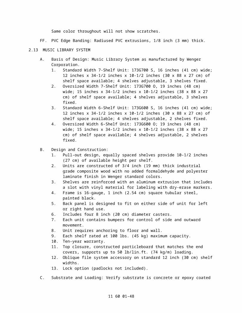
1) Standard veneer. Finish selected from mfg. standard stain.2) Custom Color: ____.3) Seat Rise Mechanism: Maintenance free gravity assist with noise
dampening seat stops.c. Cushion Foam: High Resiliency cold-molded polyurethane with a minimum of 3
inches (76 mm) thick.11. Back:
a. Fully Upholstered Seat Back: Fully upholstered outer back panel includes an inner 1/2 inch (13 mm) plywood seat panel to provide supporting structure. Inner wood panel is contoured for additional comfort. Fabric conceals attachment brackets and hardware.
b. Wood Seat Back: 13-ply 11/16 inch (17.5 mm) thick veneer plywood with edges that are stained to match the veneered faces.1) Standard veneer. Finish selected from mfg. standard stain.2) Custom Color: ____.
c. Cushion foam: High resiliency polyurethane is a minimum of 3 inches (76 mm) thick. Back cushion is shaped to provide lumbar support for long-term comfort.
d. Pitch: 10 degrees.e. Pitch: 14 degrees.f. Pitch: 18 degrees.g. Pitch: 22 degrees.h. Pitch: 26 degrees.i. Pitch: Custom angle. Refer to drawings.
12. Armrests:a. Polypropylene Armrest: Black polypropylene armrest with a textured finish for
an attractive and low maintenance finish.b. Wood Armrest: Solid beech hardwood with rounded corners for a stylish
appearance.1) Standard veneer. Finish selected from mfg. standard stain.2) Custom Color: ____.
C. Fabrication:1. Fabricate floor standards to fit slope of floor so that standards are plumb and maintain
chairs at the required relationship to the vertical.2. Upholstery: Fabricate upholstered chairs with fabric free of creases and wrinkles.
Install warp and woof of fabric and pattern in consistent direction.
D. ADA/ABA:1. ADA Swing-out Standard: The ADA swing-out standard allows easy access to the
seat when transferring from a seated position while maintaining a uniform appearance in the facility. A simple locking lift mechanism allows for easy operation.
2. Removable Seating: Individual seats for companion seating are equipped with a steel retractable wheel bracket so they can be easily rolled into place when needed. A simple release pedal will disengage the wheels.
E. Materials:1. Hardwood Lumber: Clear Beech, plain-sawn or sliced.2. Beech Veneer Hardwood Plywood: HPVA HP-1, 11-ply, AA-grade, rotary cut. The
seat back must be a minimum of 13-ply 11/16 inch (17.5 mm) thick plywood. The seat bottom must be a minimum of 7-ply 7/16 inch (11 mm) thick veneer plywood. Plywood edges are stained to match the veneered faces. The arm caps on the standards shall be solid beech wood.
3. Medium Density Fiberboard: ANSI A208.2, Grade MD.4. Wood Finishes: Manufacturer's standard finish and stain.5. High-Pressure Decorative Laminate: NEMA LD-3, Grade VGS.6. Plastic: Polypropylene copolymer IF-727. High impact, injection molded
11 60 01-48

polypropylene. Polypropylene outer seat and back panel includes a flange around the sides to provide fabric protection. Textured finish for an attractive and low maintenance surface.
7. Cushion Foam: Raw material provided by BASF Germany. Flexible, cellular, cold-molded, contoured polyurethane foam, flame-retardant-treated.
F. Row and Seat Numbers: Plastic with black lettering.1. Plastic Finish: Brass.2. Plastic Finish: Copper.3. Plastic Finish: Aluminum.4. Attachment: 3M adhesive.5. Attachment: Visible fasteners or brads.
G. Aisle Lighting: As manufactured by Vista.1. Transformers as required.2. Aisle lights shall be low voltage system and concealed under aisle standard.3. Aisle lights shall meet code requirements of 0.2 foot candles to light the aisle and row
numbers.4. The standard shall be provided with a flex steel conduit whip affixed to end standard
and extends a minimum of 18 inches beyond the standard.5. Aisle lighting shall be inaudible.
H. Aisle Lighting: As manufactured by Tivoli.1. Transformers as required.2. Aisle lights shall be low voltage system and concealed under aisle standard.3. Aisle lights shall meet code requirements of 0.2 foot candles to light the aisle and row
numbers.4. The standard shall be provided with a flex steel conduit whip affixed to end standard
and extends a minimum of 18 inches beyond the standard.5. Aisle lighting shall be inaudible.
I. Donor Plaques: Plastic with black lettering. Donor plaques are blank for customer engraving 1 inch x 3 inches (25 mm x 76 mm).1. Plastic Finish: Brass.2. Plastic Finish: Copper.3. Plastic Finish: Aluminum.4. Attachment: 3M adhesive.5. Attachment: Visible fasteners or brads.
2.22 FIXED SEATING - NEW YORK SERIES
A. Basis of Design: New York Series Fixed Audience Seating as manufactured by Wenger Corporation.
B. Fixed Audience Seating: Audience seating with welded tubular steel standard with attractive enclosure, upholstered back and seat with cold-molded foam cushions, seat and back covers, arm rest, and maintenance free self-lifting seats.1. Upholstery: Minimum CAL-TB-117 Flame-retardant Treated.
a. Color and Pattern: As selected from manufacturer's standard fabrics.b. Color and Pattern: Custom color, manufacturer and pattern.
2. Chair Width: 19 inches (483 mm) as measured from center of armrest to center of opposite armrest.
3. Chair Width: 20 inches (508 mm) as measured from center of armrest to center of opposite armrest.
4. Chair Width: 21 inches (533 mm) as measured from center of armrest to center of opposite armrest.
5. Chair Width: 22 inches (559 mm) as measured from center of armrest to center of
11 60 01-49

opposite armrest.6. Chair Width: 23 inches (584 mm) as measured from center of armrest to center of
opposite armrest.7. Chair Width: Width as indicated as measured from center of armrest to center of
opposite armrest.8. Chair Mounting Standards: Welded 14 gauge tubular steel standard with attractive
armrest and directly anchored to floor through 11 gauge steel foot.9. Aisle Standards:
a. Fully Upholstered Aisle Standard: Plywood core over steel structure with fabric upholstered exterior surface. The arm caps on the standards shall be solid beech wood or polypropylene.1) As selected from manufacturer's standard fabrics.2) Custom color, manufacturer and pattern.
b. Wood Veneer Aisle Standard: Plywood exteriors over steel structure with stained veneered faces. The arm caps on the standards shall be solid beech wood stained to match veneer surfaces.1) Standard veneer. Finish selected from mfg. standard stain.2) Custom Color: ____.
10. Seat:a. Polypropylene Seat Bottom: Black polypropylene outer seat panel includes a
flange around the sides to provide fabric protection. Textured finish for an attractive and low maintenance surface attached to a 9/16 inch (14 mm) plywood core.
b. Seat Rise Mechanism: Maintenance free gravity assist with noise dampening seat stops.
c. Cushion foam: High resiliency cold-molded polyurethane is a minimum of 2 inches (51 mm) thick.
11. Back:a. Polypropylene Seat Back: Black polypropylene outer back panel includes a
flange around the sides to provide fabric protection. Textured finish for an attractive and low maintenance surface attached to a 9/16 inch (14 mm) plywood core.
b. Cushion foam: High resiliency polyurethane with a contoured range of 2 inches to 3 inches (51 mm to 76 mm) thick. Back cushion is shaped to provide lumbar support for long-term comfort.
c. Pitch: 10 degrees.d. Pitch: 14 degrees.e. Pitch: 18 degrees.f. Pitch: 22 degrees.g. Pitch: 26 degrees.h. Pitch: Custom angle. Refer to drawings.
12. Armrests:a. Polypropylene Armrest: Black polypropylene armrest with a textured finish for
an attractive and low maintenance finish.b. Wood Armrest: Solid beech hardwood with rounded corners for a stylish
appearance.1) Standard Hardwood. Finish to be selected from mfg. standard stain.2) Custom Color: ____.
C. Fabrication:1. Fabricate floor standards to fit slope of floor so that standards are plumb and maintain
chairs at the required relationship to the vertical.2. Upholstery: Fabricate upholstered chairs with fabric free of creases and wrinkles.
Install warp and woof of fabric and pattern in consistent direction.
D. ADA/ABA:
11 60 01-50

1. ADA Swing-out Standard: The ADA swing-out standard allows easy access to the seat when transferring from a seated position while maintaining a uniform appearance in the facility. A simple locking lift mechanism allows for easy operation.
2. Removable Seating: Individual seats for companion seating are equipped with a steel retractable wheel bracket so they can be easily rolled into place when needed. A simple release pedal will disengage the wheels.
E. Materials:1. Hardwood Lumber: Clear Beech, plain-sawn or sliced.2. Beech Veneer Hardwood Plywood: HPVA HP-1, 11-ply, AA-grade, rotary cut. The
seat back must be a minimum of 13-ply 11/16 inch (17.5 mm) thick plywood. The seat bottom must be a minimum of 7-ply 7/16 inch (11 mm) thick veneer plywood. Plywood edges are stained to match the veneered faces. The arm caps on the standards shall be solid beech wood.
3. Medium Density Fiberboard: ANSI A208.2, Grade MD.4. Wood Finishes: Manufacturer's standard finish and stain.5. High-Pressure Decorative Laminate: NEMA LD-3, Grade VGS.6. Plastic: Polypropylene copolymer IF-727. High impact, injection molded
polypropylene. Polypropylene outer seat and back panel includes a flange around the sides to provide fabric protection. Textured finish for an attractive and low maintenance surface.
7. Cushion Foam: Raw material provided by BASF Germany. Flexible, cellular, cold-molded, contoured polyurethane foam, flame-retardant-treated.
F. Row and Seat Numbers: Plastic with black lettering.1. Plastic Finish: Brass.2. Plastic Finish: Copper.3. Plastic Finish: Aluminum.4. Attachment: 3M adhesive.5. Attachment: Visible fasteners or brads.
G. Aisle Lighting: As manufactured by Vista.1. Transformers as required.2. Aisle lights shall be low voltage system and concealed under aisle standard.3. Aisle lights shall meet code requirements of 0.2 foot candles to light the aisle and row
numbers.4. The standard shall be provided with a flex steel conduit whip affixed to end standard
and extends a minimum of 18 inches beyond the standard.5. Aisle lighting shall be inaudible.
H. Aisle Lighting: As manufactured by Tivoli.1. Transformers as required.2. Aisle lights shall be low voltage system and concealed under aisle standard.3. Aisle lights shall meet code requirements of 0.2 foot candles to light the aisle and row
numbers.4. The standard shall be provided with a flex steel conduit whip affixed to end standard
and extends a minimum of 18 inches beyond the standard.5. Aisle lighting shall be inaudible.
I. Donor Plaques: Plastic with black lettering. Donor plaques are blank for customer engraving 1 inch x 3 inches (25 mm x 76 mm).1. Plastic Finish: Brass.2. Plastic Finish: Copper.3. Plastic Finish: Aluminum.4. Attachment: 3M adhesive.5. Attachment: Visible fasteners or brads.
11 60 01-51

2.23 FIXED SEATING - SYDNEY SERIES
A. Basis of Design: Sydney Series Fixed Audience Seating as manufactured by Wenger Corporation.
B. Fixed Audience Seating: Audience seating with welded tubular steel standard with attractive enclosure, upholstered back and seat with cold-molded foam cushions, seat and back covers, arm rest, and maintenance free self-lifting seats.1. Upholstery: Minimum CAL-TB-117 Flame-retardant Treated.
a. Color and Pattern: As selected from manufacturer's standard fabrics.b. Color and Pattern: Custom color, manufacturer and pattern.
2. Chair Width: 19 inch (483 mm) as measured from center of armrest to center of opposite armrest.
3. Chair Width: 20 inch (508 mm) as measured from center of armrest to center of opposite armrest.
4. Chair Width: 21 inch (533 mm) as measured from center of armrest to center of opposite armrest.
5. Chair Width: 22 inch (559 mm) as measured from center of armrest to center of opposite armrest.
6. Chair Width: 23 inch (584 mm) as measured from center of armrest to center of opposite armrest.
7. Chair Width: Width as indicated as measured from center of armrest to center of opposite armrest.
8. Chair Mounting Standards: Welded 14 gauge tubular steel standard with attractive armrest and directly anchored to floor through 11 gauge steel foot.
9. Aisle Standards:a. Fully Upholstered Aisle Standard: Plywood core over steel structure with fabric
upholstered exterior surface. The arm caps on the standards shall be solid beech wood or polypropylene.1) As selected from manufacturer's standard fabrics.2) Custom color, manufacturer and pattern.
b. Wood Veneer Aisle Standard: Plywood exteriors over steel structure with stained veneered faces. The arm caps on the standards shall be solid beech wood stained to match veneer surfaces.1) Standard veneer. Finish selected from mfg. standard stain.2) Custom Color: ____.
10. Seat:a. Polypropylene Seat Bottom: Black polypropylene outer seat panel includes a
flange around the sides to provide fabric protection. Textured finish for an attractive and low maintenance surface attached to a 9/16 inch (14 mm) plywood core.1) Seat Rise Mechanism: Maintenance free gravity assist with noise
dampening seat stops.2) Cushion foam: High resiliency cold-molded polyurethane is a minimum of
4 inches (102 mm) thick.b. Wood Seat Bottom: 7-ply 7/16 inch (11 mm) thick veneer plywood with edges
that are stained to match the veneered faces. Veneered Plywood attached to 16 gauge welded steel frame.1) Seat Rise Mechanism: Quiet rise 3/4 fold seat with adjustable torsion
spring and dampener.2) Standard veneer. Finish selected from mfg. standard stain.3) Custom Color ____.4) Cushion foam: High Resiliency cold-molded polyurethane with a
minimum of 3 inches (76 mm) and encapsulating a welded steel frame with a serpentine spring support.
11. Back:
11 60 01-52

a. Polypropylene Seat Back: Black polypropylene outer back panel includes a flange around the sides to provide fabric protection. Textured finish for an attractive and low maintenance surface attached to a 9/16 inch (14.3 mm) plywood core.
b. Wood Seat Back: 13-ply 11/16 inch (17.5 mm) thick veneer plywood with edges that are stained to match the veneered faces.1) Standard veneer. Finish selected from mfg. standard stain.2) Custom Color: ____.
c. Cushion foam: High resiliency polyurethane is a minimum of 3 inches (76 mm) thick. Back cushion is shaped to provide lumbar support for long-term comfort.
d. Pitch: 10 degrees.e. Pitch: 14 degrees.f. Pitch: 18 degrees.g. Pitch: 22 degrees.h. Pitch: 26 degrees.i. Pitch: Custom angle. Refer to drawings.
12. Armrests:a. Polypropylene Armrest: Black polypropylene armrest with a textured finish for
an attractive and low maintenance finish.b. Wood Armrest: Solid beech hardwood with rounded corners for a stylish
appearance.1) Standard veneer. Finish selected from mfg. standard stain.2) Custom Color: ____.
C. Fabrication:1. Fabricate floor standards to fit slope of floor so that standards are plumb and maintain
chairs at the required relationship to the vertical.2. Upholstery: Fabricate upholstered chairs with fabric free of creases and wrinkles.
Install warp and woof of fabric and pattern in consistent direction.
D. ADA/ABA:1. ADA Swing-out Standard: The ADA swing-out standard allows easy access to the
seat when transferring from a seated position while maintaining a uniform appearance in the facility. A simple locking lift mechanism allows for easy operation.
2. Removable Seating: Individual seats for companion seating are equipped with a steel retractable wheel bracket so they can be easily rolled into place when needed. A simple release pedal will disengage the wheels.
E. Materials:1. Hardwood Lumber: Clear Beech, plain-sawn or sliced.2. Beech Veneer Hardwood Plywood: HPVA HP-1, 11-ply, AA-grade, rotary cut. The
seat back must be a minimum of 13-ply 11/16 inch (17.5 mm) thick plywood. The seat bottom must be a minimum of 7-ply 7/16 inch (11 mm) thick veneer plywood. Plywood edges are stained to match the veneered faces. The arm caps on the standards shall be solid beech wood.
3. Medium Density Fiberboard: ANSI A208.2, Grade MD.4. Wood Finishes: Manufacturer's standard finish and stain.5. High-Pressure Decorative Laminate: NEMA LD-3, Grade VGS.6. Plastic: Polypropylene copolymer IF-727. High impact, injection molded
polypropylene. Polypropylene outer seat and back panel includes a flange around the sides to provide fabric protection. Textured finish for an attractive and low maintenance surface.
7. Cushion Foam: Raw material provided by BASF Germany. Flexible, cellular, cold-molded, contoured polyurethane foam, flame-retardant-treated.
F. Row and Seat Numbers: Plastic with black lettering.
11 60 01-53

1. Plastic Finish: Brass.2. Plastic Finish: Copper.3. Plastic Finish: Aluminum.4. Attachment: 3M adhesive.5. Attachment: Visible fasteners or brads.
G. Aisle Lighting: As manufactured by Vista.1. Transformers as required.2. Aisle lights shall be low voltage system and concealed under aisle standard.3. Aisle lights shall meet code requirements of 0.2 foot candles to light the aisle and row
numbers.4. The standard shall be provided with a flex steel conduit whip affixed to end standard
and extends a minimum of 18 inches beyond the standard.5. Aisle lighting shall be inaudible.
H. Aisle Lighting: As manufactured by Tivoli.1. Transformers as required.2. Aisle lights shall be low voltage system and concealed under aisle standard.3. Aisle lights shall meet code requirements of 0.2 foot candles to light the aisle and row
numbers.4. The standard shall be provided with a flex steel conduit whip affixed to end standard
and extends a minimum of 18 inches beyond the standard.5. Aisle lighting shall be inaudible.
I. Donor Plaques: Plastic with black lettering. Donor plaques are blank for customer engraving 1 inch x 3 inches (25 mm x 76 mm).1. Plastic Finish: Brass.2. Plastic Finish: Copper.3. Plastic Finish: Aluminum.4. Attachment: 3M adhesive.5. Attachment: Visible fasteners or brads.
2.24 MODULAR SOUND-ISOLATION PRACTICE ROOMS
A. Basis of Design: SoundLok Sound-Isolating Practice Rooms as manufactured by Wenger Corporation. Factory-fabricated, modular, sound-isolation enclosures with sound transmission characteristics meeting requirements. Enclosures shall be internally wired for power, lighting, and ventilation controls. Site-fabricated enclosures and enclosures with site-installed gaskets and sealants shall not be allowed. Modifications to room on site affect acoustical performance and laboratory test data.1. Rooms shall be assembled from factory-gasketed modular components that allow
reconfiguration and relocation without component modification or loss of acoustical performance.
2. Interior Room Height: 7 feet 6 inches (2260 mm).3. Interior Room Height: 8 feet 0 inches (2438 mm).4. Interior Room Height: 8 feet 6 inches (2591 mm).5. Interior Room Height: 9 feet 0 inches (2743 mm).6. Interior Room Height: 9 feet 6 inches (2896 mm).7. Interior Room Height: 10 feet 0 inches (3048 mm).
B. Room Variation: Sound-isolation practice rooms (with VAE) shall be equipped with manufacturer's Virtual Acoustical Environment (VAE) simulation system with integrated wiring, speakers, and microphones capable of providing room sonic environment simulation of a range in preset and customized practice and performance environments.
C. Room Variation: Sound-isolation practice rooms (upgradeable to VAE) shall be equipped with integrated and wiring, raceways, panel cutouts for speakers and microphones, all
11 60 01-54

concealed within wall panels to allow room to be upgraded with the VAE technology system in the future. No external mounted wiring, raceways, speakers, or microphones allowed.
D. Room Variation: Sound-isolation practice rooms (non-upgradeable to VAE) shall be standard room that does NOT have the ability to be upgraded to the VAE technology system.
E. Airborne Noise Reduction: Sound-isolation practice rooms with 410 cu. ft. (11.6 cu. m) interior volume, 34 percent perforated interior panels, 12 inch (304 mm) airspace between modules, mounted on concrete floor construction, tested as follows:1. NIC 41 from exterior to interior of module, per independent lab test.2. NIC 63 from interior of one module to interior of adjacent module, with 12 inches (304
mm) airspace between modules, per independent lab test.
F. Ambient Noise at Center of sound-isolation room: Lighting and ventilating systems operating, per ANSI S 12.2: Not exceeding NC 25.
G. Reverberation Time: Sound-Isolation Practice Rooms with 640 cu. ft. (18.12 cu. m) interior volume: in contiguous octave bands, center frequencies from 125 to 4000 Hz, per ASTM C 423: 0.45 plus or minus 0.10 seconds.
H. Ventilation Air Change Rate: Sound-isolation practice rooms with 406 cu. ft. (11.5 cu. m) interior volume shall have 35 air changes per hour. Other rooms will vary according to size and occupancy.
I. Sound-Isolating Door Sound Transmission Class: With full window, per internal testing only: STC 46.
J. HVAC Ceiling Panel Sound Transmission Class: Per internal testing only: STC 45.
K. Safety Glazing Products: 16 CFR 1201.
L. Seismic Performance: Comply with ASCE 7, "Minimum Design Loads for Buildings and Other Structures": Section 9, "Earthquake Loads" based upon seismic design criteria indicated.
M. Wall Frame: 14-gauge/0.075 inch (1.91 mm) thick steel channel with 1-1/4 inch (31.75 mm) thick factory-applied acoustical gasketing at floor slab, with 3/4 inch (19 mm) leveling adjustment.
N. Wall Panels: 30 inches by 4 inches (762 by 102 mm) thick composite panels, consisting of an exterior face of 16-gauge/0.0598 inch (1.52 mm) sheet steel, an interior face of 22-gauge/0.0299 inch (0.76 mm) perforated or solid sheet steel, with sound-attenuation material at panels indicated as perforated.1. Acoustical Seal: Two continuous acoustical gaskets factory-mounted at panel
perimeter.2. Panel Attachment: Two or more mechanical locks on each vertical edge to align and
engage adjoining panel and create compression seal between panels.3. Corner Assembly: Same construction as wall panels.4. Power Panel (one per unit): Same construction as wall panels, with factory pre-wiring
meeting ETL and NEC requirements, consisting of conduit, wiring, junction and electrical boxes, and airtight cover plates, and including the following:a. Two duplex receptacles.b. Dimmable switches, occupancy sensors and connectors for lighting control
(and fans, and VAE, as required).c. Three empty raceways for future Owner-installed circuitry.
5. Acoustic Vision Lite Wall Panel: Same construction as wall panels, 30 inches (762 mm) wide, with nominal 26.5 by 65.5 inches (673 by 1664 mm) vision lite,
11 60 01-55

respectively, consisting of 1/4 and 3/8 inch (6.0 and 9.5 mm) thick laminated safety glass with 3 inches (76 mm) interspace, mounted in metal frame. Refer to Drawings for location.a. Provide one-way vision safety glass. Refer to Drawings for location.
6. Horizontal Window, 90 degrees wide (2286mm), with nominal 32 inches x 81-3/4 inches (813mm x 2076mm) vision lite.
7. Horizontal Window, 60 degrees (1524mm) wide, with nominal 32 inches x 51-3/4 inches (813mm x 1314mm) vision lite.
8. Communication Wall Panels: Where indicated: Same construction as wall panels, size and configuration indicated, with factory installed rough-in for addition wiring by owner, consisting of conduit, junction boxes, and airtight cover plates, and includes one pre-wired quad outlet.
O. Ceiling Frame: Sheet steel, 16-gauge/0.053 inch (1.34 mm) thick, with clamping mechanism for compressing ceiling panel acoustical gaskets, with external support beam where required by room size.
P. Ceiling Panels: Same construction as wall panels, 15 inches wide by 6 inches thick (381 mm wide by 152 mm thick), with the following characteristics:1. Acoustical Seal: Two continuous acoustical gaskets factory mounted at panel
perimeter.2. Panel Attachment: Two mechanical locks on each vertical edge to align and engage
adjoining panel and create compression seal between panels.3. Sprinkler Ceiling Panels: Where indicated, panels fabricated with predrilled holes to
enable fire sprinkler system installation specified elsewhere. Furnish covers for installations not requiring sprinkler piping penetration.
4. Light Panels: Where indicated, highly efficient, 50/60Hz, 100-277 Volt AC, 40 Watt, 1' x 4' dimmable edge-lit LED flat panels. Technical information; power factor: 0.9, lifetime (L70): 50,000 hours, LED chip type: 2835, number of LEDs (per panel): 216, physical dimensions: 11.83 inches (W) x 47.63 inches (L) x 0.39 inches (H), color temperature: 5000k (standard), lumens: 4200, beam angle: 120 degrees, RA value: 80, compatible with 0-10V dimmers. Compliance & approvals: ETL, FCC, DLC QPL, IP rating: damp locations.
Q. Doors: 2 inches (51 mm) thick composite panel, consisting of an exterior face of 16-gauge/0.053 inch (1.34 mm) sheet steel, an interior face of 14-gauge/0.068 inch- (1.72 mm-) sheet steel, and a core of sound-attenuation material, sound transmission class (STC) 46 (based on internal testing), size and swing as indicated on Drawings, and as follows:1. Acoustical Seals: Magnetic seal plus compression seal at head and jambs, and
adjustable sweep seal at door bottom.2. Hinge: Cam-type wrap around continuous barrel hinge, CR 1010 steel.3. Door size: 3 feet (914 mm) wide standard.4. Door size: 4 feet (1219 mm) wide.5. Door size: 6 feet (1829 mm) wide double door with removable mullion.6. Door Vision Lite: Nominal 22 by 66 inches (559 by 1676 mm), glazed with safety
glass.a. Provide one-way vision safety glass. Refer to drawings for location.
7. Metal threshold: Stainless steel, 1/2 inch (12.7 mm) high.8. Lockset: ANSI/BHMA A156.2, Series 4000, Grade 1, cylindrical lock with lever handle,
6 pin cylinder, classroom function locking, satin nickel finish.9. Keying: Each keyed differently.10. Keying: Interchangeable core, with cylinder specified in Section 08 71 53 - Security
Door Hardware.
R. Virtual Acoustical Environment (VAE) System: Manufacturer's standard electronic sound system providing integrated record and playback capabilities, with nine virtual acoustical
11 60 01-56

simulations within sound-isolating room, including:1. Eight speakers mounted in pre-wired corner panel speaker enclosures.2. Push-button operated control panel with associated electronic components.3. Microphone Wall Panel: Same construction as solid wall panels, with two integrated
microphone mounts and two microphones.4. Systems using non-integrated components or external reverberation/special effects
components are not acceptable.
S. Ceiling Ventilation System: Provide manufacturer's, built-in fan standard free-standing room ventilation system:1. Vent Panels: 15 inches (381 mm) wide by 6 inches (152 mm) thick panel with integral
acoustical air plenum, with 1-1/2 inches (38 mm) sound-absorbing duct liner and four 90-degree bends.
2. Fan Exhaust Panels: 120 cfm (0.057 cu. m/s) exhaust fan mounted in panel with same construction panel as vent intake panel. Number of fan panels equal to number of vent panels. Fan exhausts to surrounding space.
T. Ceiling Ventilation System, Connection to Building HVAC System:1. Vent Panels: 15 inch (381 mm) wide by 6-inch (152 mm) thick panel with integral
acoustical air plenum, with 1-1/2 inch (38 mm) sound-absorbing duct liner and four 90-degree bends, with 8 inch (203 mm) diameter duct connector. Capacity: 120 cfm (.057 cu. m/s) maximum per vent panel. Configured in pairs of intake and exhaust panels as indicated. Flexible ductwork specified in mechanical section and provided by others.
U. Closure Panels: Provide vertical and horizontal closures between modules and above modules to close off space visually. Constructed of 3/4 inch (19 mm) thick composite wood with low-pressure thermofused laminates.1. Color: Oyster.2. Color: Vanilla.3. Color: Warm Sand.
V. Floor Component System: Where indicated: Sheet vinyl flooring bonded to high density 1-1/8 inches (22 mm) thick particleboard, supported by steel under structure, with 1-1/2 inches (38 mm) sound-absorbing vibration isolators, supported on 6-1/4 Hz natural frequency vibration isolators with 1/4 inches (6 mm) maximum deflection under typical loading, joined by mechanical fasteners and aligned by interlocking steel support clips. Floor fabricated for installation inside finished practice room without disassembly of modules.
W. Mirror: Mounts directly to interior solid wall panel. Metal mounting brackets in black painted finish are provided. Dimensions: 58 inches (1473 mm) high x 22 inches (559 mm) wide with 1/4 inch (6 mm) thick mirror glass, constructed with vinyl backing to prevent shattering of glass.
X. Drop-Down Technology Shelf: Mounts directly to interior solid wall panel for usage and storage of laptop computer. Shelf locks for secure storage of computer and all cables, wiring, etc. Constructed of metal frame with maple wood shelf. Includes 6-outlet surge protector, with 15 feet (4572 mm) long cord. Drop-down shelf dimension: 30 inches (762 mm) wide x 15-1/2 inches (394 mm) deep. Overall dimensions (in locked position): 35 inches (889 mm) wide x 25-1/2 inches (648 mm) high x 7-1/4 inches (184 mm) deep.
Y. Metronome/Tuner: Mounts directly to interior solid wall panel and houses battery-operated metronome/tuner, Korg Model TM40. Mounting bracket included. Overall dimensions: 4-3/4 inches (121 mm) wide x 4-3/4 inches (121 mm) high x 1 inch (25 mm) thick.
Z. Steel Sheet: Cold-rolled, ASTM A 1008/A 1008M, commercial steel, Type B.
AA. Sound Attenuation Material: ASTM C 665, Type I, 1.5-lb/cu. ft (24 kg/cu. m).
11 60 01-57

BB. Finish for Electrical Cover Plates:1. Light, Fan and VAE Switch (as required): Satin chrome finish.2. All other: Painted to match wall panel colors.
CC. Finishes for Other Exposed Components: Iron phosphate pre-coat and thermo-set epoxy resin powder coat (baked) finish.1. Colors:
a. Wall and ceiling panels: Oyster.b. Wall and ceiling panels: Vanilla.c. Wall and ceiling panels: Warm Sand.d. Floor rail and door: Charcoal Grey.e. Floor rail and door: Warm Beige.
2.25 MOBILE PERFORMANCE SYSTEM
A. Basis of Design: Showmobile as manufactured by Wenger Corporation.
B. Dimensions (Nominal):1. Travel Mode Dimensions (Nominal):
a. Body Length: 28'-0" (8.53 m).b. Width: 8'-5" (2.56 m).c. Height: 13'-2" (4.01 m).d. Tongue Height: 22 inches (55.8 cm).
2. Performance Mode Dimensions (Nominal):a. Stage Performance Dimensions:
1) Main Stage Floor: 28'-0" x 6'-6" (8.53 m x 1.98 m).2) Hydraulic Stage: 28'-0" x 8'-0" (7.31 m x 2.44 m).3) Stage Height from Ground: 42 to 52 inches (107 - 132 cm).4) Back of Wall to Leading Stage Edge: 14'-3" (4.34 m).5) Performance Stage Size: 28'-0" x 14'-6" (8.53 m x 4.42 m).
b. Acoustical Shell Interior Performance Dimensions:1) Canopy Height from Stage at Highest Setting: 17'-4" (5.28 m).2) Canopy Height from Ground at Highest Setting: 21'-10" (6.40 m).3) Upstage Canopy Height from Floor: 9'-3" (2.82 m).4) Overall Overhead Roof/Canopy Depth: 13'-2" (4.01 m).
C. Weight (Nominal): Gross Vehicle Weight Rating (GVWR) = 16,000 lbs (7257 kg).
D. Chassis Construction:1. Structure:
a. Constructed of two cold roll formed structural 4 inch x 12 inch x 1/4 inch (10 x 30 x 0.635 cm) carbon steel tubes.
b. Cross Members: 14-gauge structural tubes and formed steel channels on 24 inch (61 cm) centers.
c. All welded construction to provide unitized body structure.d. Perimeter shall be finished on all sides with steel skirting (rub rail) to provide
finished appearance and protect internal components.2. Suspension and Axles:
a. Double-axle configuration featuring two rubber-torsion type, each axle rated at 7,200 lbs (3266 kg).
b. Torsion axles shall be used to provide the smoothest possible cargo ride, lowest center of gravity, and best road handling.
c. Axle hubs shall have grease fittings for easy maintenance and shall be completely hot dip galvanized, inside and out, for weatherability.
d. Leaf-spring type axle suspension is unacceptable due to inefficient oscillation time and greater maintenance requirements.
3. Tires and Rims: LT 235/85 R16 steel-belted radial tires mounted on 8-bolt rims.
11 60 01-58

4. Brakes:a. Each axle shall have two-sided adjustable 12-volt electric brakes, 12-1/4 x 2-
1/2 inches (0.635 x 6.35 cm).b. Hitch-mounted breakaway switch system.
5. Stabilization:a. Four manual leveling jacks permanently integrated into the vehicle frame for
leveling and stabilization.b. Each jack shall have 10,000 lb (4536 kg) live load capcity.c. Two removable hand cranks.d. Due to the structural integrity of the mobile stage frame, stabilizers mounted in
the center of the trailer are not required.e. Externally-mounted, pivoting stabilizers are unacceptable.
6. Hitch:a. Trailer hitch shall feature a removable lunette ring.b. Connector for Towing Vehicle: Pintle hook connector.c. Hitch Construction: Structural carbon steel tube.
7. Storage Compartments:a. Two large, weather-sealed storage compartments located on the curb side of
the mobile stage.b. Compartment doors shall feature two stainless steel locking D-ring handles as
well as stainless steel hinge construction.c. Compartments minimum dimensions shall be 54 inches L x 17 inches D x 15
inches H (137 cm L x 43 cm D x 38 cm H).8. Finish:
a. All metal surfaces shall be primed with one coat two-component epoxy primer and one coat Sherwin-Williams Polane 8890 polyurethane enamel, a two-component, aliphatic acrylic topcoat.1) Standard auto enamel paint or galvanized finish is not acceptable.
9. Electrical System:a. The mobile stage shall be equipped with 12-volt electrical system to power
hydraulic stage, hydraulic roof and canopy and breakaway switch operations.b. The power source shall be a heavy-duty deep cycle 12-volt battery located in
the front roadside of the mobile stage.
E. Panel Construction:1. Curbside Panel: Composite acoustical panel and extruded aluminum edging:
a. Wall panel shall be a one-piece, composite structural material, which provides a seamless, weatherproof UV protected, Tedlar exterior surface, as well as a rigid surface for reflecting sound and enhancing the acoustics of musical performances.
b. Curbside panel frame shall be constructed of carbon steel welded to chassis to form a unitized body structure.
c. Curbside panel shall be surrounded by extruded aluminum fastened to the steel structure and sealed with gasketing.
d. Exterior fasteners are not acceptable.e. Minimum Thickness: 1-3/4 inches (4.4 cm).f. Curbside composite panel shall feature internal aluminum structural
reinforcement.1) Solid wood-core panels are not acceptable.
2. Roof and Canopy Construction: Steel frame, composite acoustical panel and extruded aluminum edging:a. Panels shall be composite, one-piece, lightweight, structural material, to
provide a seamless, weatherproof exterior surface as well as a rigid surface for reflecting sound and enhancing the acoustics of musical performances.
b. Frame structure shall be one-piece welded carbon steel construction integrally connected to the roof/canopy linkage system.
11 60 01-59

c. Aluminum extrusion shall seal steel frame and composite panel together to create complete, one-piece roof and canopy assemblies.
d. Extruded aluminum roof and canopy edges shall meet to form a continuous rain gutter.
e. Canvas or membranes used to seal joints between assemblies are not acceptable.
f. Minimum Thickness: 1 inch (2.5 cm).g. Roof and canopy composite panels shall feature internal aluminum structural
reinforcements.1) Solid wood-core panels are not acceptable.
h. Exterior fasteners are not acceptable.3. End Panels: Steel frame, composite acoustical panel and extruded aluminum edging:
a. Panels shall be a one-piece, lightweight, composite structural material, to provide a seamless, weatherproof exterior surface as well as a rigid surface for reflecting sound and enhancing the acoustics of musical performances.
b. Frame structure shall be one-piece, welded carbon steel hinged to the upright curbside structure.
c. End panel shall be recessed inside roof and canopy when in travel position. Extruded aluminum end panel frame shall provide a continuous rain gutter surrounded by gasketing.
d. Operating Handle: Recessed, constructed of stainless steel with integral covered, keyed-locking mechanism.
e. Latching Mechanism: Holds the end panel closed with three points of contact.f. Hinge: Continuous, end-panel hinge shall be constructed of stainless steel.g. End panel shall be adjustable between its closed position and 270 degrees out
of audience view.h. Locking mechanisms shall be provided to secure end panels in various
performance and stowed positions.i. Acoustical end panels shall have 3 adjustments, closed to 270 degrees.
F. Hydraulic Stage Construction:1. Deck Material: 3/4 inch (1.9 cm) 7-ply Douglas Fir plywood core.
a. Traffic Surface: Black, non-skid, 0.015 inches (0.038 cm) thermally fused Quad-Ripple composite overlay embossed with raised textured pattern.
b. Backer Material: 0.008 inch (0.0203 cm) thermally fused MDO overlay, functions as moisture barrier.
c. Stage deck shall be constructed of economical replaceable components in the event that damage should require decking replacement.
2. Structure: Formed steel fabricated into one-piece, unitized sytem.a. Cross Members: At 24 inches (61 cm) on center, maximum.
3. Hardware and Legs:a. Stage hinge and fasteners shall be of stainless steel. Hinge shall be
continuous to prevent gaps between main stage and hydraulic stage.b. Five adjustable support legs shall be attached to the leading edge of the
hydraulic stage to provide uniform stability and load capacity.1) Fold into position when the hydraulic stage is opened and secure for
transport to magnetic catches when closed.2) Leg Tubes: Telspar, adjustable in 1/8 inch (0.3175 cm) increments.3) Feet: 4 x 4 inch (10 x 10 cm).
4. Stage Edging: Perimeter of the stage deck shall have an extruded aluminum channel, to accommodate supplementary stage extension platforms as well as stairways, drapery skirting, rail sections, or other optional accessories.
5. Tie Downs:a. Eight tie-downs and four tie-down straps shall be provided on the main stage
for the secure transport of supplemental stage equipment.b. Tie-downs shall be flush-mounted with D-ring attachment.
11 60 01-60

G. Electrical and Hydraulic Systems:1. Power Center: 110V electrical system capable of operating from regular 110V
"household current," enabling operation of the fluorescent lighting, use of the back wall outlets and charging of the 12V-battery:a. The 110V-electrical power shall be distributed through one load center.b. Circuit Breakers: One 30-amp main breaker and three 20-amp breakers.
1) The first 20-amp breaker protects the three rows of fluorescent lighting located in the roof and canopy.
2) The second 20-amp GFI breaker protects the four duplex outlets located on the inside lower back wall.
3) The third 20-amp GFI breaker protects the one duplex outlet located near the 12-volt battery.
c. Power Cord: 50 foot (15 m), 10/3 power cord, with a 30-amp twist-lock plug.d. The load center shall be in a compartment located near the hitch end, curbside
of the mobile stage.e. A lockable weatherproof door with stainless steel hardware shall enclose the
power center and seal the compartment.f. The compartment shall also be able to store the power cord.
2. Additional Power Center: 220V electrical power distributed through a second load center.a. Circuit Breakers: One 50-amp main breaker and ten 20-amp GFI breakers.
1) Eight 20-amp GFI breakers protect the quadplex outlets for the optional lighting located in the canopy.
2) The last two 20-amp GFI breakers protect the duplex outlets for the optional lighting located in roof.
b. Power Cord: 50 foot (15 m), 50-amp, 6/4 power cord.c. Located in the same compartment beside the standard 110V load center.d. The compartment shall be able to store both power cords.
3. General Lighting: Three rows of fluorescent lighting, two rows in overhead canopy and one row in roof:a. Fixtures: 40-watt tandem with safety retaining clips.b. All fluorescent lights shall be on one circuit and shall feature warm color-
temperature bulbs.4. Double Articulated Roof/Canopy and Stage Hydraulic Deployment System:
a. Hydraulic deployment system shall open and close double articulated roof/canopy as well as raise and lower the hydraulic stage.
b. Double articulated roof-canopy must be continuously adjustable from fully open to fully closed to allow for flexibility in presentation.
c. Support: Structural steel columns on curbside wall with a dual hydraulic linkage actuation system.
d. Roof/Canopy Controls: Two, two-way hydraulic cylinders with solenoid control powered by an on-board 12-volt, DC hydraulic power unit.
e. Hydraulic deployment system shall be safety protected by counterbalance and velocity check components.
f. Hydraulic Stage Controls: Two, two-way hydraulic cylinders with solenoid control powered by 12-volt, DC hydraulic power unit.
g. Dimensions for appropriate acoustical, visual, lighting, and functional benefits:1) Distance from stage to rear of roof in open position: Minimum 9'-2" (2.79
m).2) Distance from stage to roof/canopy pivot point in open position:
Minimum 14'-11" (4.55 m).3) Distance from stage to front edge of canopy in open position: Minimum
17'-3" (5.25 m).4) Distance from stage to front edge of light bar in open position: Minimum
17'-9" (5.41 m).h. Roof/Canopy shall open to required dimensions to provide the following:
11 60 01-61

1) Maximum performance space volume, which optimizes performance and audience acoustics.
2) Allows the use of choral risers and other performance platforms on-stage, while still maintaining headroom for performers.
3) 17 x 28 foot (5.2 m x 8.5 m) visual frame with open ends for optimum audience viewing.
4) Allows the use of standard size theatrical lighting fixtures along the rear of the roofline without occupying critical headroom for performers.
5. Remote-Control Module:a. Removable weatherproof remote-control module with 12 foot (3.6 m) cord shall
be provided to operate the roof/canopy and the hydraulic stage.b. Remote-control module shall contain toggle-type switches for opening and
closing the roof/canopy, and raising and lowering the hydraulic stage.c. Remote cable shall plug into the front of the mobile stage with a positive lock-
type connector.d. Remote-control module shall be keyed for operational security.e. Remote-control module acts as backup to the wireless remote controller for
hydraulic leveling.
H. Weatherproofing and Finishing:1. Construction: Mating edges of all major assemblies (roof, canopy, curbside panel,
end panels) shall have extruded aluminum edges with gasketing.a. Aluminum edges shall provide integral channels which direct water away from
the roof of the mobile stage.2. Wall Panels: Composite panels shall provide a seamless exterior surface that is UV
protected and impervious to the elements.a. High gloss fiberglass reinforced plastic surface.
3. Deck Material:a. Stage decking shall have a treated core.b. Textured surface shall provide a non-skid performance area.
4. Fasteners and Hardware: To minimize the effects of corrosive elements and weather, as well as improving overall appearance, exposed fasteners shall be unacceptable on all exterior roof, canopy, and curbside panels.a. All exterior hardware materials shall be stainless steel, plastic or aluminum.
5. Coatings: All metal surfaces shall be primed with one coat two-component epoxy primer and one coat Sherwin-Williams Polane 8890 polyurethane enamel, a two-component, aliphatic acrylic topcoat.a. The epoxy primer and polyurethane topcoat create a barrier coat, which
prevents moisture reaching any steel parts.b. Paint shall provide high gloss retention for excellent exterior physical and
chemical performance properties, excellent hardness and impact resistance and excellent mar and abrasion resistance.
c. Finish shall not create a chalky white nor dulled appearance over time (oxidation).
6. Colors:a. Exterior Top: Bright white.b. Exterior Bottom: Blackthron.c. Interior wall and roof/canopy: Bright white.d. Stage Deck: Black.
I. Stairway: Adjustable all-terrain stair with handrails.1. Stairway shall incorporate a parallelogram design, which allows for the rise of the
steps to increase or decrease compensate for irregularities in ground level.2. Stairway may be positioned anywhere around the hydraulic stage and stage extension
perimeters.3. Treads: Extruded aluminum.
11 60 01-62

4. Adjustable height from 37 to 50 inches (94 - 127 cm).5. Meets all applicable safety codes and conditions.
J. Support and Background:1. Design shall meet Society of Automotive Engineers (SAE) Standards as well as the
Code of Federal Regulations, which includes Department of Transportation (DOT), Federal Motor Vehicle Safety Standards (FMVSS) and Federal Motor Carrier Safety Regulations (FMCSR).
2. Product Training: Upon delivery, complete training on operation and maintenance shall be conducted by manufacturers authorized representative.
K. Included Options:1. Hydraulic Leveling System with Wireless Remote and Auto Level Feature:
a. Jacks: Four automatic, hydraulic leveling jacks permanently integrated into the vehicle frame for leveling and stabilization.1) Each jack shall have 10,000 lb (4536 kg) live load capacity and a 10 inch
(25cm) diameter swiveling stabilization pad2) Jacks shall be powered by the standard 12-volt electrical system,
independently controllable, and will position the stage of the mobile stage 40 to 45 inches (102-114 cm) above level ground.
3) Each jack shall feature an integrated counterbalance valve safety device.b. Hand-Held Wireless, Remote-Control Unit:
1) Operated on a protected FM radio frequency that can only be received by the on-board receiver.
2) Powered by a nine-volt battery.3) Receiver Unit: Powered by the 12-volt battery in the mobile stage.4) Auto shut-off feature shall be provided to prevent battery drain.5) Provides independent up/down control of the four stabilizing jacks, the
open/close function of the roof/canopy, the raise/lower function of the hydraulic stage, and the auto-leveling system.
c. Auto-Leveling Feature: Controlled by wireless remote.1) One-button feature allows the mobile stage to electronically sense its
out-of-level position, and will automatically adjust the hydraulic stabilizers until a level chassis position is attained.
d. Safety Features:1) Roof/Canopy raise shall not function until a level chassis position is
attained.2) Hydraulic stage shall not lower or raise until adequate roof/canopy
clearance is available.e. Standard wired controller to be supplied along with wireless remote controller
that is supplied with hydraulic leveling option.2. Disability Lift (12V-powered): Low-profile platform style wheelchair lift built into the
curbside wall of the mobile stage, with interior cover and lockable exterior access door:a. Provide manual back-up pump.b. Minimum lift capacity shall be 800 lbs.
3. Graphics: Complete exterior graphics package custom designed:a. Graphics, logo and text shall be executed with 3M acrylic vinyl in a choice of 60
colors.
L. Accessories:1. Stage Extensions: Component 4 foot x 8 foot (122 x 244 cm) variable height stage
platforms:a. Each platform shall be constructed of lightweight aluminum framing with black
Polyglass stage decking material.b. Platforms securely attach to each other or anywhere around the perimeter of
11 60 01-63

the stage.c. Legs: Variable height, 30 to 54 inches (76 - 137 cm) with appropriate
connection hardware.d. Weight: 120 lb (55 kg) maximum.e. May also be used independently for other uses.f. Stage Extension Package A: Extends the stage on both ends of the mobile
stage, for a nominal stage size of 16 feet x 40 feet (4.88 m x 12 m). Units can alternately be used to extend the front of the mobile stage. Includes:1) (4) 4 foot x 8 foot (122 x 244 cm) Stage Platforms.2) (4) 2 foot x 8 foot (61 x 244 cm) Stage Platforms.3) Legs and connectors.
g. Stage Extension Package B: Extends both ends, as in Package A, plus adds 4 feet to the front of the mobile stage, for a nominal stage size of 20 feet x 40 feet (6 m x 12 m). Units can alternately be used to extend the front of the mobile stage. Includes:1) (9) 4 foot x 8 foot (122 x 244 cm) Stage Platforms.2) (4) 2 foot x 8 foot (61 x 244 cm) Stage Platforms.3) Legs and connectors.
h. Stage Extension Package C: Extends both ends, as in Package A, plus adds 4 feet to the front of the mobile stage, for a nominal stage size of 20 feet x 40 feet (6 m x 12 m). Units can alternately be used to extend the front of the mobile stage. Includes:1) (14) 4 foot x 8 foot (122 x 244 cm) Stage Platforms.2) (4) 2 foot x 8 foot (61 x 244 cm) Stage Platforms.3) Legs and connectors.
2. Stage Drapery Skirting: Pleated outdoor drapery skirting with Velcro attachment and weighted bottom shall be provided for the front and sides of the stage.a. Color: _____.
3. Additional Stairways: Of same design as included stairway.a. Number: _____.
4. Lighting Packages: Canopy PAR lights mounted to the canopy light frame assembly bars.a. Bars and lights shall be designed to swing out for performance use or returned
to storage position for travel without being dismantled from the canopy.b. Lighting Package - Canopy:
1) (4) Canopy light frame assemblies.2) (16) 500-watt wide flood quartz lamps.3) (16) Par 56 light cans with gel frames and gels.
c. Lighting Package - Roof:1) (2) Canopy light bars with attachment bolts.2) (4) 500-watt wide flood quartz lamps.3) (4) Par 56 light cans with gel frames and gels.
d. Roof/Canopy Lighting Controller System: Professional lighting controller system allows control of the roof and canopy par lights:1) Up to 128 programmable scenes may be placed in memory.2) Features include three user programmable chases, audio sync, freeze
and blackout.3) One Lightronics TL-3012 hand operated memory controller with 50 foot
cable.4) Three dimmer packs (installed).5) Required cables.
5. Portable Generator:a. Industrial 6,600 continuous watts rated - 11.7 HP, four-stroke, single cylinder,
air cooled with 6.5 gallon fuel tank.b. Does not supply power to the optional canopy and roof lighting packages.c. Shall not be attached to the mobile stage.
11 60 01-64

6. Spare Tire and Wheel: LT 235/85 R16 steel belted radial tires mounted on an eight-bolt rim.
7. Secondary Control Unit: Connects directly into control compartment:a. Operates all functions of the mobile stage with hydraulic leveling option.b. Serves as backup or replacement for wireless remote.
2.26 FIRE CURTAIN SYSTEMS, BRAIL FIRE CURTAIN
A. Fire Curtain Hoist:1. General Description:
a. Furnish and install a motorized brail lift, automatically closing fire safety curtain as indicated on the drawings. The curtain shall fold up above the proscenium arch, and shall lap the wall not less than 18 inch (457 mm) at each side of the proscenium opening and 24 inch (610 mm) at the top of the proscenium opening.
b. The curtain shall be arranged to comply with applicable codes and, in general, intercept fire and smoke and prevent glow from severe fire on the stage from showing on the auditorium side for at least thirty (30) minutes in order to permit safe egress of all people from the auditorium.
c. The curtain shall close by gravity due to over-balance of the curtain as specified below. Emergency closing shall occur as specified in NFPA 80 or as required by local codes when the fire line is released or fusible links separate.
2. Special Conditions: It is the intention of this specification to provide a fully functioning fire safety curtain system. Actual equipment and components shall reflect building conditions and approved construction drawings. All dimensions shall be field verified by the Rigging Contractor.
3. ZetexPlus Fire Safety Curtain: The curtain shall be fabricated from tightly woven J.R. Clancy ZetexPlus 1210-ZP non-wire inserted, non-asbestos, non-carcinogenic silica based cloth, 12 x 7 weave of .070 inch (1.8 mm) thickness weighing at least 40 ounces per square yard (1.35 KG/sq m). The curtain shall be listed and approved by the State of California Fire Marshall the NYC Material and Equipment Acceptance Division, and shall bear a certification label from a nationally recognized listing agency. All strips of fabric shall be in continuous lengths running the full height of the curtain. There shall be no horizontal seams. Each seam shall be sewn with two lines of stitching using fiberglass thread. Top and bottom pockets shall be 6 inch (152.4 mm). The bottom pocket shall be equipped with a 3 inch (76.2 mm) yield pad filled with Zetex. D-rings shall be sewn 18 inch (457.2 mm) apart in vertical rows at each lift line location.
4. Sides of curtain shall have bronze guides every 18 inch (457.2 mm), securely fastened to a 6 inch (152.4 mm) hem with at least three bolts or rivets, or as required by the governing code.
5. Guides: Provide 1/4 inch (6.4 mm) wire rope guide at each side of the curtain. These cables shall be attached to a ring at the stage floor level and extend to the roof steel or gridiron where they shall be attached with 3/8 inch x 6 inch (9.525 mm x 152.4 mm) turnbuckles, thimbles, swage sleeves and other fittings as required.
6. Smoke Pockets: Furnish and install one pair of smoke pockets to extend from the stage floor to a point above the top of the raised curtain or to the height specified in the drawings. Pockets shall consist of an 8 inch (203.2 mm) deep "Z" channel formed from 1/4 inch (6.4 mm) steel plate and a 1/4 inch x 18 inch (6.4 mm x 457.2 mm) steel plate which shall be bolted to the channels on 2 feet-0 inch (609.6 mm) centers. Welded construction shall not be accepted. Channels shall be anchored to the walls on 4 feet-0 inch (1,219 mm) centers.
7. Smoke Seal: Provide a smoke seal consisting of a triple layer of folded fabric fastened above the proscenium with a mounting clamp so it rubs the curtain and seals the top of the opening. The fabric shall be Zetex 800 cloth with a minimum weight of 27 oz/yd² (0.9 KG/sq m).
11 60 01-65

8. Fire Curtain Hoist:a. Hoist shall consist of a cable drum, coupled to an electric gear motor. Hoist
shall have a 1,100lb (500 KG) lifting capacity at a rate of 25 feet/min (0.13 m/s). The hoist shall be fully enclosed and supplied with a sturdy metal stand or wall brackets.
b. The cable drum shall be of welded steel construction and carry 75 feet (22.86 m) of 5/16 inch (7.9 mm) diameter 7x19 galvanized utility cable. Twin guards shall keep the cable in the drum groove.
c. The hoist (and curtain) shall be locked in position by the motor brake located within the enclosure. Releasing the fire line shall disengage the motor brake, permitting the cable drum to rotate, lowering the curtain. The brake handle shall extend through the top of the case, for easy attachment to the end of the fire line. No more than 20lbs (9 KG) of tension in the fire line shall be required to hold the full load capacity of the winch.
d. The unit shall be equipped with an adjustable hydraulic speed governor to provide maximum control and safety in the closing of the fire curtain and to establish the travel time.
e. Gearmotor:1) The motor and helical/bevel gearbox shall be an integrated unit, with the
first stage pinion mounted directly on the motor's armature shaft.2) Motors shall be totally enclosed fan cooled (TEFC). The motor shall have
a minimum AGMA service factor of 1.0 for constant operation.3) The gear case shall be cast iron for protection against shock damage.
The output shaft shall have double lip oil seals to prevent leaks. The gearing service factor shall be a minimum of 1.0 with a mechanical strength service factor of 1.25.
f. Rotary Limit Switch:1) Rotary limit switch assembly shall have four independently adjustable
switch/cam sets. Cams shall be driven by a geared assembly.2) Switches shall have snap acting contacts.3) Switches shall be mounted within the winch base as to allow for easy
adjustment of the switch settings.4) Rotary limit switches shall be Ravasi.
g. All components in the hoist shall be fully enclosed. Access panels for adjustment and maintenance shall be removable without removing the hoist from service.
h. Fixed Speed Starter:1) The hoist shall be controlled by a UL 508E listed, full voltage, self-
protected, reversing starter. Enclosure shall be NEMA 12 with hinged, latching cover. The interior of the starter cabinet shall be "touch safe" per IEC 204-1 "Protection against direct contact" rules.
2) The NEMA/IEC, magnetically operated, mechanically and electrically interlocked and reversing starter shall be sized to match the hoist motor horsepower and shall be rated for plugging and jogging. Units shall incorporate UL508E Type 2, non-welding, positive break contactors.
3) Overcurrent protection shall be provided by an IEC Class 10 overload. Short circuit protection shall be provided by a circuit breaker.
4) Starters shall be wired so that operation of the normal end of travel limit switches shall only allow movement away from the limit switch. Operation of an overtravel limit switch shall open the line contactor, and shall not allow further movement in either direction. A spring return toggle switch shall be housed inside the starter cabinet to allow override of the overtravel limits for resetting purposes.
9. Control Station: Controls, consisting of up and down pushbuttons and an emergency stop switch, are mounted on the motor starter.
10. Guided Clew: Cable clew shall be cut from 5/16 inch (7.94 mm) minimum steel, with
11 60 01-66

the proper number of holes for proper attachment of turnbuckles for multiple cables. One larger hole for the drive cable shall be so located as to prevent the clew from jamming on its guide cables. Provide two parallel guide cables between the head block and the brail hoist to guide the clew.
11. Head Block:a. The sheave shall have a 12 inch (304.8 mm) pitch diameter, and shall be an
iron casting, with a machined groove. The sheave shall be equipped with a 1 inch (25.4 mm) diameter shaft and two tapered roller bearings.
b. Base angles shall be a minimum 2 inch x 1-1/2 inch x 1/4 inch (50.8 mm x 38.1 mm x 6.4 mm) angle.
c. Side plates shall be a minimum of 10-gauge (3.57 mm) steel, and shall fully enclose the sheave.
d. The block and associated mounting hardware shall have a recommended working load of at least 2,500lb (1.1 KG), and shall be designed for use in either upright or underhung usage.
e. Block shall be grooved for (8) 1/4 inch (6.4 mm) lift lines.12. Loft Block:
a. The sheave shall have an 8-1/2 inch (215.9 mm) outside diameter, and shall be iron casting, with a machined groove. The sheave shall be equipped with a 17 mm diameter shaft and two sealed, precision ball bearings.
b. Base angles shall be a minimum 1-1/2 inch x 1-1/2 inch x 3/16 inch (38.1 mm x 38.1 mm x 4.76 mm) angle.
c. Side plates shall be a minimum of 12-gauge (2.78 mm) steel, and shall fully enclose the sheave.
d. The block and associated mounting hardware shall have a recommended working load of at least 500lb (317 KG), and shall be designed for use in either upright or underhung usage.
e. Loft blocks shall be grooved for one 1/4 inch (6.4 mm) lift line.13. Battens: Battens shall be made of 2 inch (50.8 mm) I.D. nominal, schedule 40 black
iron pipe.14. Fire line System: The manual fire line release system shall consist of a 1/8 inch (3.2
mm) diameter wire rope, with six fusible links, side mounting pulleys as required, and two fire line release devices, each mounted in enclosures. Devices shall be mounted 5 feet-0 inch (1.54 m) above the stage floor on each side of the proscenium. All other components such as round weight arbors, arbor guards, floor pulleys, etc. required to form a fully functional fire line release system shall be provided.
15. Lift Cables: The curtain lift cables shall be 1/4 inch (6.4 mm) diameter 7x19 galvanized utility cable as specified. Cables shall be terminated with corresponding cable thimbles and two forged cable clips or a Swage sleeve fitting at each end. The curtain end of each cable shall be attached to the batten using a half pipe clamp.
16. Drive Cable: The drive cable between the brail hoist and the clew shall be 5/16 inch (7.9 mm) diameter 7x19 galvanized aircraft cable, attached to the clew using a thimble and two forged cable clips.
17. Safety Chains: Supply one more safety chain than the number of lift cables. The 1/4 inch (6.4 mm) proof coil chains shall be located between lift cables except at the ends where chains shall be 12 inch (304.8 mm) or less from the end of the batten. Chains shall be attached to the top of the curtain with pipe clamps around the top of the batten and chain shackles. The other end shall be appropriately attached to the building structure.
18. Half Pipe Clamps:a. Pipe clamps shall be made of two strips of 3/16 inch by 2 inch (3.17 mm x 50.8
mm) hot rolled steel formed to almost encompass and clamp the pipe batten leaving the bottom open. Corners shall be rounded.
b. There shall be a 3/8 inch x 1 inch (9.52 mm x 25.4 mm) hex bolt with lock nut above the batten. A 5/8 inch (15.87 mm) hole in the top of each clamp half allows the attachment of cable, chain, or other fittings.
11 60 01-67
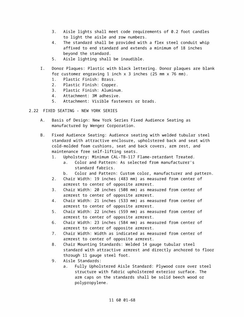
c. Half pipe clamps shall have a manufacturer's recommended load rating of at least 200 lbs. (90.7 KG).
2.27 FIRE CURTAIN SYSTEMS, STRAIGHT LIFT CURTAIN, PROSCENIUM OPENING UP TO 18'T x 34'W
A. Manual (Arbor/Lattice Track):1. General Description:
a. Furnish and install a manually operated straight lift type, automatically closing fire safety curtain for the proscenium opening indicated on the drawings. Curtain shall lap masonry not less than 18 inch at each side of the proscenium opening and 24 inch at the top of the proscenium opening.
b. The curtain shall be arranged to comply with the "International Building Code (2006)", American National Standard E1.22-2009, other applicable codes and, in general, intercept fire and smoke and prevent glow from severe fire on the stage from showing on the auditorium side for at least thirty (30) minutes in order to permit safe egress of all people from the auditorium.
c. The curtain shall close by gravity due to over-balance of the curtain as specified below. Emergency closing shall occur as specified in NFPA 80 or as required by local codes when the fire line is released or fusible links separate.
2. Special Conditions: It is the intention of this specification to provide a fully functioning fire safety curtain system. Actual equipment and components shall reflect building conditions and approved construction drawings. All dimensions shall be field verified by the Rigging Contractor.
3. ZetexPlus Fire Safety Curtain: The curtain shall be fabricated from tightly woven J.R. Clancy ZetexPlus 1210-ZP non-wire inserted, non-asbestos, non-carcinogenic silica based cloth, 12 x 7 weave of .070 inch (1.778 mm) thickness weighing at least 40 ounces per square yard (1.35 KG/sq m). The curtain shall be listed and approved by the State of California Fire Marshall, the NYC Material and Equipment Acceptance Division, and shall bear a certification label from a nationally recognized listing agency. All strips of fabric shall be in continuous lengths running the full height of the curtain. There shall be no horizontal seams. Each seam shall be sewn with two lines of stitching using fiberglass thread. Top and bottom pockets shall be 6 inch (152.4 mm). The bottom pocket shall be equipped with a 3 inch (76.2 mm) yield pad filled with ZetexPlus.
4. Sides of curtain shall have bronze guides every 18 inch (457.2 mm), securely fastened to a 6 inch (152.4 mm) hem with at least three bolts or rivets, or as required by the governing code.
5. Guides: Provide 1/4 inch (6.4 mm) wire rope guide at each side of the curtain. These cables shall be attached to a ring at the stage floor level and extend to the roof steel or gridiron where they shall be attached with 3/8 inch x 6 inch (9.525 mm x 152.4 mm) turnbuckles, thimbles, swage sleeves and other fittings as required.
6. Smoke Pockets: Furnish and install one pair of smoke pockets to extend from the stage floor to a point above the top of the raised curtain or to the height specified in the drawings. Pockets shall consist of a 6 inch (152.4 mm) deep "Z" channel formed from 1/4 inch (6.4 mm) steel plate and a 1/4 inch x 18 inch (6.4 mm x 457.2 mm) steel plate which shall be bolted to the channels on 2 feet-0 inch (609.6 mm) centers. Channels shall be anchored to the walls on 4 feet-0 inch (1.2 m) centers.
7. Smoke Seal: Provide a smoke seal consisting of a triple layer of folded fabric fastened above the proscenium with a mounting clamp so it rubs the curtain and seals the top of the opening. The fabric shall be Zetex 800 cloth with a minimum weight of 27 oz. per square yard (0.91 KG/sq m).
8. 12 inch (304.8 mm) Head Block:a. The sheave shall be an iron casting with a 12 inch (304.8 mm) outer diameter.
The machined rope and cable grooves shall have equal pitch diameters. The sheave shall be equipped with a 1 inch (25.4 mm) diameter shaft and two
11 60 01-68

tapered roller bearings.b. Base angles shall be a minimum 2 inch x 1-1/2 inch x 1/4 inch (50.8 mm x 38.1
mm x 6.35 mm) angle with the short leg turned in. The turned in leg shall be notched to allow clear passage of all cables.
c. Side plates shall be a minimum of 10-gauge (3.570 mm) steel, and shall fully enclose the sheave. Side plates shall be bolted and welded to the base angles for extra strength.
d. The block and associated mounting hardware shall have a recommended working load of at least 2,500 lbs. (1,134 KG).
e. Head blocks shall be grooved for six or eight 1/4 inch (6.4 mm) lift lines and one 3/4 inch (19.05 mm) hand line.
9. Loft Block:a. The sheave shall have an 8-1/2 inch (215.9 mm) outside diameter, and shall be
an iron casting, with a machined groove. The sheave shall be equipped with a 17 mm diameter shaft and two sealed, precision ball bearings.
b. Base angles shall be a minimum 1-1/2 inch x 1-1/2 inch x 3/16 inch (38.1 mm x 38.1 mm x 4.76 mm) angle.
c. Side plates shall be a minimum of 12-gauge (2.78 mm) steel, and shall fully enclose the sheave. Side plates shall be bolted to the base angles.
d. The block and associated mounting hardware shall have a recommended working load of at least 500 lbs. (226.8 KG), and shall be designed for use in either upright or underhung usage.
e. Loft blocks shall be cast iron sheave grooved for one 1/4 inch (6.35 mm) lift line.
10. Counterweight Arbor:a. Arbor shall be long enough to accommodate counterweights to balance the fire
curtain and related equipment.b. The arbor top shall be a fabricated weldment of 1/2 inch (12.7 mm) formed
steel plate and 7 gauge (4.76 mm) formed side plates. The side plates shall be punched to receive 8 cables, and shall be tied together with a bolt and spacer providing a tie-off point for the hand line.
c. The arbor bottom shall be 1/2 inch x 3 inch (12.7 mm x 76.2 mm) steel bar with counterweight rests to keep the weights from resting on the arbor inner nuts, and a forged steel eye for the hand line tie off.
d. The top and bottom of the arbor shall be tied together by means of two 3/4 inch (19.05 mm) steel arbor rods. The arbor rods shall have three nuts at each end, the outermost being a lock nut.
e. The top and bottom shall have bronze guides to engage the lattice track.f. Provide 14 gauge (1.98 mm) spreader plates (two minimum) on arbor rods so
they can be spaced between counterweights on 2 feet (609.6 mm) centers. Provide a retaining collar on each rod, each with a 1/4 inch (6.35 mm) set screw with red plastic knob for easy locking. One retaining collar shall be welded to the top spreader plate.
11. Lattice Track:a. The track shall consist of two 2 inch x 2 inch x 1/4 inch (50.8 mm x 50.8 mm x
6.35 mm) angles opposing each other with formed brackets alternating front and back on 2 feet (610 mm) centers. Back brackets shall contain two 9/16 inch (14.29 mm) diameter holes for proper anchorage to wall.
b. A fabricated steel bracket shall support the bottom of the lattice. Bracket shall have ample clearance for passage of hand line.
12. Automatic Floor Block:a. The cast iron sheave shall have a 12 inch (304.8 mm) outside diameter, and
shall be an iron casting, with a groove for a 1 inch (25.4 mm) rope.b. The sheave shall be equipped with a 1 inch (25.4 mm) diameter machined steel
shaft and two tapered roller bearings.c. The tension block shall be held in place and guided by two 3/4 inch (19.05 mm)
11 60 01-69

diameter rods, each equipped with adjustable locking collar to limit sheave travel.
13. Battens: Battens shall be made of 2 inch I.D. nominal, schedule 40 black iron pipe.14. Fire line System: The manual fire line release system shall consist of a 1/8 inch
diameter wire rope, with six fusible links, side mounting pulleys as required, and two fire line release devices, each mounted in enclosures. Devices shall be mounted 5 feet (1,524 mm) above the stage floor on each side of the proscenium. All other components such as the fire curtain arbor release, round weight arbors, arbor guards, floor pulleys, etc. required to form a fully functional fire line release system shall be provided.
15. Hand line:a. Hand line shall be 3/4 inch (19.1 mm) in diameter, employing a 3-strand
composite construction combining filament and staple/spun polyester wrapped around fibrillated polyolefin.
b. The hand line shall contain an identifying tape showing the manufacturer's name, phone number, website, and year of manufacture.
c. The hand line shall contain a red safety/wear indicator that shall become visible as the rope nears the end of its useful life.
d. The rope shall hold knots well and be easily spliced. Rope shall not be subject to rotting, mildew, or moisture damage nor shall its length be affected by changes in humidity.
e. Tape ends before cutting. Attach to arbor with two half hitches or bowline and tape end to standing line with electrical tape.
f. Hand lines shall be SureGrip rope.16. Lift Cables: The curtain lift cables shall be 1/4 inch (6.4 mm) diameter 7x19
galvanized utility cable as specified. Cables shall be terminated with corresponding cable thimbles and two forged cable clips or a Swage sleeve fitting at each end. The curtain end of each cable shall be attached to the batten using a half pipe clamp.
17. Safety Chains: Supply one more safety chain than the number of lift cables. 1/4 inch proof coil chains shall be located between lift cables except at the ends where chains shall be 12 inch or less from the end of the batten. Chains shall be attached to the top of the curtain with pipe clamps around the top of the batten and chain shackles. The other end shall be appropriately attached to the building structure.
B. Fire Curtain Hoist:1. General Description:
a. Furnish and install a motorized straight lift type, automatically closing fire safety curtain for the proscenium opening indicated on the drawings. Curtain shall lap masonry not less than 18 inch (457.2 mm) at each side of the proscenium opening and 24 inch (609.6 mm) at the top of the proscenium opening.
b. The curtain shall be arranged to comply with the "International Building Code (2006)", American National Standard E1.22-2009, other applicable codes and, in general, intercept fire and smoke and prevent glow from severe fire on the stage from showing on the auditorium side for at least thirty (30) minutes in order to permit safe egress of all people from the auditorium.
c. The curtain shall close by gravity, with the speed of descent controlled by a hydraulic speed regulator. Emergency closing shall occur as specified in NFPA 80 or as required by local codes when the fire line is released or fusible links separate.
2. Special Conditions: It is the intention of this specification to provide a fully functioning fire safety curtain system. Actual equipment and components shall reflect building conditions and approved construction drawings. All dimensions shall be field verified by the Rigging Contractor.
3. ZetexPlus Fire Safety Curtain: The curtain shall be fabricated from tightly woven J.R. Clancy ZetexPlus 1210-ZP non-wire inserted, non-asbestos, non-carcinogenic silica based cloth, 12 x 7 weave of .070 inch (1.8 mm) thickness weighing at least 40
11 60 01-70
ounces per square yard (1.35 KG/sq m). The curtain shall be listed and approved by the State of California Fire Marshal, the NYC Material and Equipment Acceptance Division, and shall bear a certification label from a nationally recognized listing agency. All strips of fabric shall be in continuous lengths running the full height of the curtain. There shall be no horizontal seams. Each seam shall be sewn with two lines of stitching using fiberglass thread. Top and bottom pockets shall be 6 inch (152.4 mm). The bottom pocket shall be equipped with a 3 inch (76.2 mm) yield pad filled with ZetexPlus.
4. Sides of curtain shall have bronze guides every 18 inch (457.2 mm), securely fastened to a 6 inch (152.4 mm) hem with at least three bolts or rivets, or as required by the governing code.
5. Guides: Provide 1/4 inch (6.4 mm) wire rope guide at each side of the curtain. These cables shall be attached to a ring at the stage floor level and extend to the roof steel or gridiron where they shall be attached with 3/8 inch x 6 inch (9.525 mm x 152.4 mm) turnbuckles, thimbles, swage sleeves and other fittings as required.
6. Smoke Pockets: Furnish and install one pair of smoke pockets to extend from the stage floor to a point above the top of the raised curtain or to the height specified in the drawings. Pockets shall consist of a 6 inch deep "Z" channel formed from 1/4 inch (6.4 mm) steel plate and a 1/4 inch x 18 inch (6.4 mm x 457.2 mm) steel plate which shall be bolted to the channels on 2 feet-0 inch (609.6 mm) centers. Channels shall be anchored to the walls on 4 feet-0 inch (1,219 mm) centers.
7. Smoke Seal: Provide a smoke seal consisting of a triple layer of folded fabric fastened above the proscenium with a mounting clamp so it rubs the curtain and seals the top of the opening. The fabric shall be Zetex 800 cloth with a minimum weight of 27 oz. per square yard (0.91 KG/sq m).
8. Fire Curtain Hoist:a. Hoist shall consist of a cable drum, coupled to an electric gear motor. Hoist
shall have a 1,100lb (500 KG) lifting capacity at a rate of 25 feet per minute (0.13 m/s). The hoist shall be fully enclosed and supplied with a sturdy metal stand or wall brackets.
b. The cable drum shall be of welded steel construction and carry 75 feet (22.86 m) of 5/16 inch (7.94 mm) diameter 7X19 galvanized utility cable. Twin guards shall keep the cable in the drum groove.
c. The hoist (and curtain) shall be locked in position by the motor brake located within the enclosure. Releasing the fire line shall disengage the motor brake, permitting the cable drum to rotate, lowering the curtain. The brake handle shall extend through the top of the case, for easy attachment to the end of the fire line. No more than 20lbs (9 KG) of tension in the fire line shall be required to hold the full load capacity of the winch.
d. The unit shall be equipped with an adjustable hydraulic speed governor to provide maximum control and safety in the closing of the fire curtain and to establish the travel time.
e. Gearmotor:1) The motor and helical/bevel gearbox shall be an integrated unit, with the
first stage pinion mounted directly on the motor's armature shaft.2) Motors shall be totally enclosed fan cooled (TEFC). The motor shall have
a minimum AGMA service factor of 1.0 for constant operation.3) The gear case shall be cast iron for protection against shock damage.
The output shaft shall have double lip oil seals to prevent leaks. The gearing service factor shall be a minimum of 1.0 with a mechanical strength service factor of 1.25.
f. Rotary Limit Switch:1) Rotary limit switch assembly shall have four independently adjustable
switch/cam sets. Cams shall be driven by a geared assembly.2) Switches shall have snap acting contacts.3) Switches shall be mounted within the winch base as to allow for easy
11 60 01-71

adjustment of the switch settings.4) Rotary limit switches shall be Ravasi.
g. All components in the hoist shall be fully enclosed. Access panels for adjustment and maintenance shall be removable without removing the hoist from service.
h. Fixed Speed Starter:1) The hoist shall be controlled by a UL 508E listed, full voltage, self
protected, reversing starter. Enclosure shall be NEMA 12 with hinged, latching cover. The interior of the starter cabinet shall be "touch safe" per IEC 204-1 "Protection against direct contact" rules.
2) The NEMA/IEC, magnetically operated, mechanically and electrically interlocked, reversing starter shall be sized to match the hoist motor horsepower and shall be rated for plugging and jogging. Units shall incorporate UL508E Type 2, non-welding, positive break contactors.
3) Overcurrent protection shall be provided by an IEC Class 10 overload. Short circuit protection shall be provided by a circuit breaker.
4) Starters shall be wired so that operation of the normal end of travel limit switches shall only allow movement away from the limit switch. Operation of an overtravel limit switch shall open the line contactor, and shall not allow further movement in either direction. A spring return toggle switch shall be housed inside the starter cabinet to allow override of the overtravel limits for resetting purposes.
5) The fire curtain hoist shall be sized to accommodate the fire curtain and all associated hardware. The hoist shall include a push button control station. Emergency lowering speed shall be controlled by a hydraulic speed regulator. Hoist shall meet ANSE E1.22 - 2009 "Entertainment Technology Fire Safety Curtain Systems" or NFPA 80 "Standard for Fire Doors and Other Opening Protectives - 2007".
9. Control Station: Controls, consisting of up and down pushbuttons and an emergency stop switch, are mounted on the motor starter.
10. Battens: Battens shall be made of 2 inch (50.8 mm) I.D. nominal, schedule 40 black iron pipe.
11. Fire line System: The manual fire line release system shall consist of a 1/8 inch (3.2 mm) diameter wire rope, with six UL listed fusible links that release at 165 degree F (74 degree C), side mounting pulleys as required, and two fire line release devices, each mounted in a steel enclosure with acrylic viewing window that contains a positive method to release the fire line. Devices shall be mounted 5 feet (1,524 mm) above the stage floor on each side of the proscenium. All other components such as round weight arbors, arbor guards, floor pulleys, etc. required to form a fully functional fire line release system shall be provided.
12. Lift Cables: The curtain lift cables shall be 1/4 inch (6.4 mm) diameter 7x19 galvanized utility cable as specified. Cables shall be terminated with corresponding cable thimbles and two forged cable clips or a Swage sleeve fitting at each end. The curtain end of each cable shall be attached to the batten using a half pipe clamp.
13. Safety Chains: Supply one more safety chain than the number of lift cables. 1/4 inch (6.4 mm) minimum, proof coil chains shall be located between lift cables except at the ends where chains shall be 12 inch (304.8 mm) or less from the end of the batten. Chains shall be attached to the top of the curtain with pipe clamps around the top of the batten and chain shackles. The other end shall be appropriately attached to the building structure.
C. Line Shaft Hoist:1. General Description:
a. Furnish and install a motorized straight lift type, automatically closing fire safety curtain for the proscenium opening indicated on the drawings. Curtain shall lap masonry not less than 18 inch (457.2 mm) at each side of the proscenium
11 60 01-72

opening and 24 inch (609.6 mm) at the top of the proscenium opening.b. The curtain shall be arranged to comply with the "International Building Code
(2006)", American National Standard E1.22-2009, other applicable codes and, in general, intercept fire and smoke and prevent glow from severe fire on the stage from showing on the auditorium side for at least thirty (30) minutes in order to permit safe egress of all people from the auditorium.
c. The curtain shall close by gravity, with the speed of descent controlled by a hydraulic speed regulator. Emergency closing shall occur as specified in NFPA 80 or as required by local codes when the fire line is released or fusible links separate.
2. Special Conditions: It is the intention of this specification to provide a fully functioning fire safety curtain system. Actual equipment and components shall reflect building conditions and approved construction drawings. All dimensions shall be field verified by the Rigging Contractor.
3. ZetexPlus Fire Safety Curtain: The curtain shall be fabricated from tightly woven J.R. Clancy ZetexPlus 1210-ZP non-wire inserted, non-asbestos, non-carcinogenic silica based cloth, 12 x 7 weave of .070 inch (1.8 mm) thickness weighing at least 40 ounces per square yard (1.35 KG/sq m). The curtain shall be listed and approved by the State of California Fire Marshal, the NYC Material and Equipment Acceptance Division, and shall bear a certification label from a nationally recognized listing agency. All strips of fabric shall be in continuous lengths running the full height of the curtain. There shall be no horizontal seams. Each seam shall be sewn with two lines of stitching using fiberglass thread. Top and bottom pockets shall be 6 inch (152.4 mm). The bottom pocket shall be equipped with a 3 inch (76.2 mm) yield pad filled with ZetexPlus.
4. Sides of curtain shall have bronze guides every 18 inch (457.2 mm), securely fastened to a 6 inch (152.4 mm) hem with at least three bolts or rivets, or as required by the governing code.
5. Guides: Provide 1/4 inch (6.4 mm) wire rope guide at each side of the curtain. These cables shall be attached to a ring at the stage floor level and extend to the roof steel or gridiron where they shall be attached with 3/8 inch x 6 inch (9.525 mm x 152.4 mm) turnbuckles, thimbles, swage sleeves and other fittings as required.
6. Smoke Pockets: Furnish and install one pair of smoke pockets to extend from the stage floor to a point above the top of the raised curtain or to the height specified in the drawings. Pockets shall consist of a 6 inch deep "Z" channel formed from 1/4 inch (6.4 mm) steel plate and a 1/4 inch x 18 inch (6.4 mm x 457.2 mm) steel plate which shall be bolted to the channels on 2 feet-0 inch (609.6 mm) centers. Channels shall be anchored to the walls on 4 feet-0 inch (1,219 mm) centers.
7. Smoke Seal: Provide a smoke seal consisting of a triple layer of folded fabric fastened above the proscenium with a mounting clamp so it rubs the curtain and seals the top of the opening. The fabric shall be Zetex 800 cloth with a minimum weight of 27 oz. per square yard (0.91 KG/sq m).
8. Line Shaft Fire Curtain Hoist:a. The hoist shall consist of a gearmotor assembly, a drum for each lift line, and
interconnecting shafts. The gearmotor assembly shall include a brake release and a hydraulic speed regulator, allowing the curtain to close at a controlled rate of speed when the brake is released by the activation of the fire line. The hoist shall have a minimum1,400 lb (635 KG) lifting capacity at a rate of 25 feet per minute (0.127 m/s).
b. Gearmotor:1) The motor, primary brake and gearbox shall be an integrated unit, with
the first stage pinion gear and the primary brake both mounted directly on the motor's armature shaft. No couplings shall be permitted between the motor, primary brake and gear reducer.
2) Motors shall be totally enclosed fan cooled (TEFC). The motor shall have a minimum AGMA service factor of 1.0 for constant operation.
11 60 01-73

3) The gear reducer shall be a helical bevel reducer. The gear case shall be cast iron for protection against shock damage. The output shaft(s) shall have double lip oil seals to prevent leaks. The gearing service factor shall be a minimum of 1.0 with a mechanical strength service factor of 1.25.
4) Brakes shall be normally spring applied, direct acting, electrically released, and equipped with a manual release. The brake shall be an AC / DC electro-magnetic unit with a minimum retarding torque equal to 200 percent of motor full load torque.
c. Drums.1) Each helical drum shall be supported by a sturdy steel base, holding the
elements of the drum assembly in proper alignment. Both ends of each drum shall be supported by a self-aligning flange bearing.
2) Alternate drums shall be threaded in opposite directions, to keep the batten from "walking" as its elevation changes.
3) Drums shall be interconnected by shafts with universal joints at each end. Shafts without universal joints are not acceptable.
d. Rotary Limit Switches:1) Rotary limit switch assemblies shall have two or four independently
adjustable switch/cam sets as required. Cams shall be driven by a geared assembly.
2) Switches shall have snap acting contacts.3) Rotary limit switches shall be driven directly or by roller chains. If roller
chains are used, sprockets shall be pinned to prevent slipping and sized for maximum usable rotation of switch cams. The input shaft and drive chain shall be fully guarded.
4) Switches shall be mounted to the hoist base to allow for easy adjustment of the switch settings.
e. Fixed Speed Starter:1) The traction drive hoist shall be controlled by a UL 508E listed, full
voltage, self protected, reversing starter. Enclosure shall be NEMA 12 with hinged, latching cover. The interior of the starter cabinet shall be "touch safe" per IEC 204-1 "Protection against direct contact" rules.
2) The NEMA/IEC, magnetically operated, mechanically and electrically interlocked, reversing starter shall be sized to match the hoist motor horsepower and shall be rated for plugging and jogging. Units shall incorporate UL508E Type 2, non-welding, positive break contactors.
3) Overcurrent protection shall be provided by an IEC Class 10 overload. Short circuit protection shall be provided by a circuit breaker.
4) Starters shall be wired so that operation of the normal end of travel limit switches shall only allow movement away from the limit switch. Operation of an overtravel limit switch shall open the line contactor, and shall not allow further movement in either direction. A spring return toggle switch shall be housed inside the starter cabinet to allow override of the overtravel limits for resetting purposes.
9. Control Stations: Two control stations shall be provided in wall mounted NEMA 12 enclosures. Each shall contain hold to operate (dead man) Up and Down pushbuttons, and a mushroom head emergency stop pushbutton.
10. Battens: Battens shall be made of 2 inch (50.8 mm) I.D. nominal, schedule 40 black iron pipe.
11. Fire line System: The manual fire line release system shall consist of a 1/8 inch (3.2 mm) diameter wire rope, with six fusible links, side mounting pulleys as required, and two fire line release devices, each mounted in a steel enclosure with acrylic viewing window that contains a positive method to release the fire line. Devices shall be mounted 5 feet (1,524 mm) above the stage floor on each side of the proscenium. All other components such as round weight arbors, arbor guards, floor pulleys, etc. required to form a fully functional fire line release system shall be provided.
11 60 01-74

12. Lift Cables: The curtain lift cables shall be 1/4 inch (6.4 mm) diameter 7x19 galvanized utility cable as specified. Cables shall be terminated with corresponding cable thimbles and two forged cable clips or a Swage sleeve fitting at each end. The curtain end of each cable shall be attached to the batten using a half pipe clamp.
13. Safety Chains: Supply one more safety chain than the number of lift cables. 1/4 inch (6.4 mm) minimum, proof coil chains shall be located between lift cables except at the ends where chains shall be 12 inch (304.8 mm) or less from the end of the batten. Chains shall be attached to the top of the curtain with pipe clamps around the top of the batten and chain shackles. The other end shall be appropriately attached to the building structure.
D. Traction Drive Hoist.1. General Description:
a. Furnish and install a motorized straight lift type, automatically closing fire safety curtain for the proscenium opening indicated on the drawings. Curtain shall lap masonry not less than 18 inch (457.2 mm) at each side of the proscenium opening and 24 inch (609.6 mm) at the top of the proscenium opening.
b. The curtain shall be arranged to comply with the "International Building Code (2006)", American National Standard E1.22-2009, other applicable codes and, in general, intercept fire and smoke and prevent glow from severe fire on the stage from showing on the auditorium side for at least thirty (30) minutes in order to permit safe egress of all people from the auditorium.
c. The curtain shall close by gravity due to over-balance of the curtain as specified below. Emergency closing shall occur as specified in NFPA 80 or as required by local codes when the fire line is released or fusible links separate.
2. Special Conditions: It is the intention of this specification to provide a fully functioning fire safety curtain system. Actual equipment and components shall reflect building conditions and approved construction drawings. All dimensions shall be field verified by the Rigging Contractor.
3. ZetexPlus Fire Safety Curtain: The curtain shall be fabricated from tightly woven J.R. Clancy ZetexPlus 1210-ZP non-wire inserted, non-asbestos, non-carcinogenic silica based cloth, 12 x 7 weave of .070 inch (1.778 mm) thickness weighing at least 40 ounces per square yard (1.35 KG/sq m). The curtain shall be listed and approved by the State of California Fire Marshall, the NYC Material Acceptance and Equipment Acceptance Division, and shall bear a certification label from a nationally recognized listing agency. All strips of fabric shall be in continuous lengths running the full height of the curtain. There shall be no horizontal seams. Each seam shall be sewn with two lines of stitching using fiberglass thread. Top and bottom pockets shall be 6 inch (152.4 mm). The bottom pocket shall be equipped with a 3 inch (76.2 mm) yield pad filled with ZetexPlus.
4. Sides of curtain shall have bronze guides every 18 inch (457.2 mm), securely fastened to a 6 inch (152.4 mm) hem with at least three bolts or rivets, or as required by the governing code.
5. Guides: Provide 1/4 inch (6.4 mm) wire rope guide at each side of the curtain. These cables shall be attached to a ring at the stage floor level and extend to the roof steel or gridiron where they shall be attached with 3/8 inch x 6 inch (9.525 mm x 152.4 mm) turnbuckles, thimbles, swage sleeves and other fittings as required.
6. Smoke Pockets: Furnish and install one pair of smoke pockets to extend from the stage floor to a point above the top of the raised curtain or to the height specified in the drawings. Pockets shall consist of a 6 inch deep "Z" channel formed from 1/4 inch (6.4 mm) steel plate and a 1/4 inch x 18 inch (6.4 mm x 457.2 mm) steel plate which shall be bolted to the channels on 2 feet-0 inch (609.6 mm) centers. Channels shall be anchored to the walls on 4 feet-0 inch (1,219 mm) centers.
7. Smoke Seal: Provide a smoke seal consisting of a triple layer of folded fabric fastened above the proscenium with a mounting clamp so it rubs the curtain and seals the top of the opening. The fabric shall be Zetex 800 cloth with a minimum weight of 27 oz.
11 60 01-75

per square yard (0.91 KG/sq m).8. Traction Style Fire Curtain Hoist:
a. The hoist shall consist of a traction sheave and a manual clutch with throw out fork, direct coupled and keyed to the output shaft of the gearbox. The entire assembly shall be mounted on a heavy channel base. The hoist shall have a 2,000lb (907.2 KG) lifting capacity at a rate of 25 feet per minute (0.127 m/s).
b. The iron or steel sheave shall be a minimum diameter of 40 times cable diameter with V-grooves for the number and diameter of lift lines required.
c. The clutch shall be rated for the applied load. The clutch lever arm shall be kept engaged by tension in the fire line that passes through a pulley in the handle. Release of the clutch is ensured by an overbalance weight acting on the arm.
d. Gearmotor:1) The motor, primary brake and gearbox shall be an integrated unit, with
the first stage pinion gear and the primary brake both mounted directly on the motor's armature shaft. No couplings shall be permitted between the motor, primary brake and gear reducer.
2) Motor shall be totally enclosed fan cooled (TEFC). The motor shall have a minimum AGMA service factor of 1.0 for constant operation.
3) The gear reducer shall be a combination helical/bevel reducer. The gear case shall be cast iron for protection against shock damage. The output shaft(s) shall have double lip oil seals to prevent leaks. The gearing service factor shall be a minimum of 1.0 with a mechanical strength service factor of 1.25.
4) Brakes shall be normally spring applied, direct acting, electrically released, and equipped with a manual release. The brake shall be an AC / DC electro-magnetic unit with a minimum retarding torque equal to 200 percent of motor full load torque.
e. Four direct struck limit switches shall be installed so that they are operated by the fire curtain arbor. These shall provide top and bottom limits of travel as well as overtravel functions. The direct struck limit switches shall be heavy duty, lever operated rotary head units, with positive opening contacts. Direct struck limit switches shall be Telemecanique ZCKJ series or equal.
f. Fixed Speed Starter:1) The traction drive hoist shall be controlled by a UL 508E listed, full
voltage, self protected, reversing starter. Enclosure shall be NEMA 12 with hinged, latching cover. The interior of the starter cabinet shall be "touch safe" per IEC 204-1 "Protection against direct contact" rules.
2) The NEMA/IEC, magnetically operated, mechanically and electrically interlocked, reversing starter shall be sized to match the hoist motor horsepower and shall be rated for plugging and jogging. Units shall incorporate UL508E Type 2, non-welding, positive break contactors.
3) Overcurrent protection shall be provided by an IEC Class 10 overload. Short circuit protection shall be provided by a circuit breaker.
4) Starters shall be wired so that operation of the normal end of travel limit switches shall only allow movement away from the limit switch. Operation of an overtravel limit switch shall open the line contactor, and shall not allow further movement in either direction. A spring return toggle switch shall be housed inside the starter cabinet to allow override of the overtravel limits for resetting purposes.
g. Control Stations: Two control stations shall be provided in wall mounted NEMA 12 enclosures. Each shall contain hold to operate (dead man) Up and Down pushbuttons, and a mushroom head emergency stop pushbutton.
9. Loft Block:a. The sheave shall have a 12 inch (304.8 mm) pitch diameter, and shall be an
iron casting, with a machined groove. The sheave shall be equipped with a 1 inch (25.4 mm) diameter shaft and two tapered roller bearings.
11 60 01-76

b. Base angles shall be a minimum 2 inch x 1-1/2 inch x 1/4 inch (50.8 mm x 38.1 mm x 6.4 mm) angle.
c. Side plates shall be a minimum of 10-gauge (3.57 mm) steel, and shall fully enclose the sheave. Side plates shall be bolted to the base angles.
d. The block and associated mounting hardware shall have a recommended working load of at least 1400 lbs (635 KG), and shall be designed for use in either upright or underhung usage.
e. Loft blocks shall have cast iron sheave grooved for one 3/8 inch (9.5 mm) lift line.
10. Counterweight Arbor:a. Arbor shall be long enough to accommodate counterweights to balance the fire
curtain and related equipment.b. The arbor top shall be a fabricated weldment of 1/2 inch(12.7 mm) formed steel
plate and 7 gauge (4.76 mm) formed side plates. The side plates shall be punched to receive 8 cables, and shall be tied together with a bolt and spacer providing a tie-off point for the hand line.
c. The arbor bottom shall be 1/2 inch x 3 inch (12.7 mm x 76.2 mm) steel bar with counterweight rests to keep the weights from resting on the arbor inner nuts, and a forged steel eye for the hand line tie off.
d. The top and bottom of the arbor shall be tied together by means of two 3/4 inch (19.1 mm) steel arbor rods. The arbor rods shall have three nuts at each end, the outermost being a lock nut.
e. The top and bottom shall have bronze guides to engage the lattice track.f. Provide 14 gauge (1.98 mm) spreader plates (two minimum) on arbor rods so
they can be spaced between counterweights on 2 feet (609.6 mm) centers. Provide a retaining collar on each rod, each with a 1/4 inch (6.4 mm) set screw with red plastic knob for easy locking. One retaining collar shall be welded to the top spreader plate.
11. Lattice Track:a. The track shall consist of two 2 inch x 2 inch x 1/4 inch (50.8 mm x 50.8 mm x
6.4 mm) angles opposing each other with formed brackets alternating front and back on 2 feet centers. Back brackets shall contain two 9/16 inch (14.3 mm) diameter holes for proper anchorage to wall.
b. A fabricated steel bracket shall support the bottom of the lattice. Bracket shall have ample clearance for passage of hand line.
12. Battens: Battens shall be made of 2 inch (50.8 mm) I.D. nominal, schedule 40 black iron pipe.
13. Fire line System: The manual fire line release system shall consist of a 1/8 inch (3.2 mm) diameter wire rope, with six fusible links, side mounting pulleys as required, and two fire line release devices, each mounted in enclosures. Devices shall be mounted 5' (1,524 mm) above the stage floor on each side of the proscenium. All other components such as round weight arbors, arbor guards, floor pulleys, etc. required to form a fully functional fire line release system shall be provided.
14. Lift Cables: The curtain lift cables shall be 3/8 inch (9.5 mm) diameter 7 x 19 galvanized utility cable as specified. Cables shall be terminated with corresponding cable thimbles and two forged cable clips or a Swage sleeve fitting at each end. The curtain end of each cable shall be attached to the batten using a pipe clamp.
15. Safety Chains: Supply one more safety chain than the number of lift cables. 1/4 inch (6.4 mm) minimum, proof coil chains shall be located between lift cables except at the ends where chains shall be 12 inch (304.8 mm) or less from the end of the batten. Chains shall be attached to the top of the curtain with pipe clamps around the top of the batten and chain shackles. The other end shall be appropriately attached to the building structure.
E. Drum Hoist:1. General Description:
11 60 01-77

a. Furnish and install a motorized straight lift type, automatically closing fire safety curtain for the proscenium opening indicated on the drawings. Curtain shall lap masonry not less than 18 inch (457.2 mm) at each side of the proscenium opening and 24 inch (609.6 mm) at the top of the proscenium opening.
b. The curtain shall be arranged to comply with the "International Building Code (2006)", American National Standard E1.22-2009, other applicable codes and, in general, intercept fire and smoke and prevent glow from severe fire on the stage from showing on the auditorium side for at least thirty (30) minutes in order to permit safe egress of all people from the auditorium.
c. The curtain shall close by gravity due to over-balance of the curtain as specified below. Emergency closing shall occur as specified in NFPA 80 or as required by local codes when the fire line is released or fusible links separate.
2. Special Conditions: It is the intention of this specification to provide a fully functioning fire safety curtain system. Actual equipment and components shall reflect building conditions and approved construction drawings. All dimensions shall be field verified by the Rigging Contractor.
3. ZetexPlus Fire Safety Curtain: The curtain shall be fabricated from tightly woven J.R. Clancy ZetexPlus 1210-ZP non-wire inserted, non-asbestos, non-carcinogenic silica based cloth, 12 x 7 weave of .070 inch (1.778 mm) thickness weighing at least 40 ounces per square yard (1.35 KG/sq m). The curtain shall be listed and approved by the State of California Fire Marshall, the NYC Material Acceptance and Equipment Acceptance Division, and shall bear a certification label from a nationally recognized listing agency. All strips of fabric shall be in continuous lengths running the full height of the curtain. There shall be no horizontal seams. Each seam shall be sewn with two lines of stitching using fiberglass thread. Top and bottom pockets shall be 6 inch (152.4 mm). The bottom pocket shall be equipped with a 3 inch (76.2 mm) yield pad filled with ZetexPlus.
4. Sides of curtain shall have bronze guides every 18 inch (457.2 mm), securely fastened to a 6 inch (152.4 mm) hem with at least three bolts or rivets, or as required by the governing code.
5. Guides: Provide 1/4 inch (6.4 mm) wire rope guide at each side of the curtain. These cables shall be attached to a ring at the stage floor level and extend to the roof steel or gridiron where they shall be attached with 3/8 inch x 6 inch (9.525 mm x 152.4 mm) turnbuckles, thimbles, swage sleeves and other fittings as required.
6. Smoke Pockets: Furnish and install one pair of smoke pockets to extend from the stage floor to a point above the top of the raised curtain or to the height specified in the drawings. Pockets shall consist of a 6 inch deep "Z" channel formed from 1/4 inch (6.4 mm) steel plate and a 1/4 inch x 18 inch (6.4 mm x 457.2 mm) steel plate which shall be bolted to the channels on 2 feet-0 inch (609.6 mm) centers. Channels shall be anchored to the walls on 4 feet-0 inch (1,219 mm) centers.
7. Smoke Seal: Provide a smoke seal consisting of a triple layer of folded fabric fastened above the proscenium with a mounting clamp so it rubs the curtain and seals the top of the opening. The fabric shall be Zetex 800 cloth with a minimum weight of 27 oz. per square yard (0.91 KG/sq m).
8. Drum Style Fire Curtain Hoist:a. The hoist shall be mounted to allow dual drive lines to travel from either side of
the fire curtain centerline, over loft blocks and to the hoist drum.b. The hoist shall consist of a cable drum and a manual clutch with throw out fork,
direct coupled and keyed to the output shaft of the gearbox. The entire assembly shall be mounted on a heavy channel base. The hoist shall have a 2,000lb (907.2 KG) lifting capacity at a rate of 25 feet per minute (0.127 m/s).
c. The drum shall be a minimum diameter of 30 times cable diameter with helical grooves for the number and diameter of lift lines required.
d. The clutch shall be rated for the applied load. The clutch lever arm shall be kept engaged by tension in the fire line that passes through a pulley in the handle. Release of the clutch is ensured by an overbalance weight acting on the arm.
11 60 01-78

e. Gearmotor:1) The motor, primary brake and gearbox shall be an integrated unit, with
the first stage pinion gear and the primary brake both mounted directly on the motor's armature shaft. No couplings shall be permitted between the motor, primary brake and gear reducer.
2) Motor shall be totally enclosed fan cooled (TEFC). The motor shall have a minimum AGMA service factor of 1.0 for constant operation.
3) The gear reducer shall be a combination helical/bevel reducer. The gear case shall be cast iron for protection against shock damage. The output shaft(s) shall have double lip oil seals to prevent leaks. The gearing service factor shall be a minimum of 1.0 with a mechanical strength service factor of 1.25.
4) Brakes shall be normally spring applied, direct acting, electrically released, and equipped with a manual release. The brake shall be an AC / DC electro-magnetic unit with a minimum retarding torque equal to 200 percent of motor full load torque.
f. Four direct struck limit switches shall be installed so that they are operated by the fire curtain arbor. These shall provide top and bottom limits of travel as well as overtravel functions. The direct struck limit switches shall be heavy duty, lever operated rotary head units, with positive opening contacts. Direct struck limit switches shall be Telemecanique ZCKJ series or equal.
g. Fixed Speed Starter:1) The hoist shall be controlled by a UL 508E listed, full voltage, self
protected, reversing starter. Enclosure shall be NEMA 12 with hinged, latching cover. The interior of the starter cabinet shall be "touch safe" per IEC 204-1 "Protection against direct contact" rules.
2) The NEMA/IEC, magnetically operated, mechanically and electrically interlocked, reversing starter shall be sized to match the hoist motor horsepower and shall be rated for plugging and jogging. Units shall incorporate UL508E Type 2, non-welding, positive break contactors.
3) Overcurrent protection shall be provided by an IEC Class 10 overload. Short circuit protection shall be provided by a circuit breaker.
4) Starters shall be wired so that operation of the normal end of travel limit switches shall only allow movement away from the limit switch. Operation of an overtravel limit switch shall open the line contactor, and shall not allow further movement in either direction. A spring return toggle switch shall be housed inside the starter cabinet to allow override of the overtravel limits for resetting purposes.
h. Control Stations: Two control stations shall be provided in wall mounted NEMA 12 enclosures. Each shall contain hold to operate (dead man) Up and Down pushbuttons, and a mushroom head emergency stop pushbutton.
9. Loft Block:a. The sheave shall have a 12 inch (304.8 mm) pitch diameter, and shall be an
iron casting, with a machined groove. The sheave shall be equipped with a 1 (25.4 mm) diameter shaft and two tapered roller bearings.
b. Base angles shall be a minimum 2 inch x 1-1/2 inch x 1/4 inch (50.8 mm x 38.1 mm x 6.4 mm) angle.
c. Side plates shall be a minimum of 10-gauge (3.57 mm) steel, and shall fully enclose the sheave. Side plates shall be bolted to the base angles.
d. The block and associated mounting hardware shall have a recommended working load of at least 1400 lbs (635 KG), and shall be designed for use in either upright or underhung usage.
e. Loft blocks shall have cast iron sheave grooved for one 3/8 inch (9.5 mm) lift line.
10. Counterweight Arbor:a. Arbor shall be long enough to accommodate counterweights to permit normal
11 60 01-79
motorized operation of the fire curtain and emergency closure without power.b. The arbor top shall be a fabricated weldment of 1/2 inch (12.7 mm) formed
steel plate and 7 gauge (4.76 mm) formed side plates. The side plates shall be punched to receive 8 cables, and shall be tied together with a bolt and spacer providing a tie-off point for the hand line.
c. The arbor bottom shall be 1/2 inch x 3 inch (12.7 mm x 76.2 mm) steel bar with counterweight rests to keep the weights from resting on the arbor inner nuts, and a forged steel eye for the hand line tie off.
d. The top and bottom of the arbor shall be tied together by means of two 3/4 inch (19.1 mm) steel arbor rods. The arbor rods shall have three nuts at each end, the outermost being a lock nut.
e. The top and bottom shall have bronze guides to engage the lattice track.f. Provide 14 gauge (1.98 mm) spreader plates (two minimum) on arbor rods so
they can be spaced between counterweights on 2 feet (609.6 mm) centers. Provide a retaining collar on each rod, each with a 1/4 inch (6.4 mm) set screw with red plastic knob for easy locking. One retaining collar shall be welded to the top spreader plate.
11. Lattice Track:a. The track shall consist of two 2 inch x 2 inch x 1/4 inch (50.8 mm x 50.8 mm x
6.4 mm) angles opposing each other with formed brackets alternating front and back on 2 feet centers. Back brackets shall contain two 9/16 inch (14.3 mm) diameter holes for proper anchorage to wall.
b. A fabricated steel bracket shall support the bottom of the lattice. Bracket shall have ample clearance for passage of hand line.
12. Battens: Battens shall be made of 2 inch (50.8 mm) I.D. nominal, schedule 40 black iron pipe.
13. Fire line System: The manual fire line release system shall consist of a 1/8 inch (3.2 mm) diameter wire rope, with six fusible links, side mounting pulleys as required, and two fire line release devices, each mounted in enclosures. Devices shall be mounted 5 feet (1,524 mm) above the stage floor on each side of the proscenium. All other components such as round weight arbors, arbor guards, floor pulleys, etc. required to form a fully functional fire line release system shall be provided.
14. Lift Cables: The curtain lift cables shall be 3/8 inch (9.5 mm) diameter 7 x 19 galvanized utility cable as specified. Cables shall be terminated with corresponding cable thimbles and two forged cable clips or a Swage sleeve fitting at each end. The curtain end of each cable shall be attached to the batten using a pipe clamp.
15. Safety Chains: Supply one more safety chain than the number of lift cables. 1/4 inch (6.4 mm) minimum, proof coil chains shall be located between lift cables except at the ends where chains shall be 12 inch (304.8 mm) or less from the end of the batten. Chains shall be attached to the top of the curtain with pipe clamps around the top of the batten and chain shackles. The other end shall be appropriately attached to the building structure.
2.28 FIRE CURTAIN SYSTEMS, STRAIGHT LIFT CURTAIN, PROSCENIUM OPENING UP TO 22'T x 42'W
A. Manual (Arbor/Lattice Track):1. Product: Model F201m Manual Straight Lift Fire Curtain With Smoke Pocket Roller
Guide and Metal Edge Curtain Channel.2. General Description:
a. Furnish and install a manually operated straight lift type, automatically closing fire safety curtain for the proscenium opening indicated on the drawings. Curtain shall lap masonry not less than 18 inch at each side of the proscenium opening and 24 inch at the top of the proscenium opening.
b. The curtain shall be arranged to comply with the "International Building Code (2006)", American National Standard E1.22-2009, other applicable codes and,
11 60 01-80

in general, intercept fire and smoke and prevent glow from severe fire on the stage from showing on the auditorium side for at least thirty (30) minutes in order to permit safe egress of all people from the auditorium.
c. The curtain shall close by gravity due to over-balance of the curtain as specified below. Emergency closing shall occur as specified in NFPA 80 or as required by local codes when the fire line is released or fusible links separate.
3. Special Conditions: It is the intention of this specification to provide a fully functioning fire safety curtain system. Actual equipment and components shall reflect building conditions and approved construction drawings. All dimensions shall be field verified by the Rigging Contractor.
4. ZetexPlus Fire Safety Curtain: The curtain shall be fabricated from tightly woven J.R. Clancy ZetexPlus 1210-ZP non-wire inserted, non-asbestos, non-carcinogenic silica based cloth, 12 x 7 weave of .070 inch (1.778 mm) thickness weighing at least 40 ounces per square yard (1.35 KG/sq m). The curtain shall be listed and approved by the State of California Fire Marshall, the NYC Material and Equipment Acceptance Division, and shall bear a certification label from a nationally recognized listing agency. All strips of fabric shall be in continuous lengths running the full height of the curtain. There shall be no horizontal seams. Each seam shall be sewn with two lines of stitching using fiberglass thread. Top and bottom pockets shall be 6 inch (152.4 mm). The bottom pocket shall be equipped with a 3 inch (76.2 mm) yield pad filled with ZetexPlus.
5. Metal Edge Channel:a. Fire curtain vertical edges shall have u-shaped, 16 gauge (1.59 mm) steel
reinforcement 6 inch (152.4 mm) deep.b. Channels shall attach to the curtain using the curtain guide bolts.c. Channels are supplied in 5 feet (1.52 m) and 10 feet (3,04 m) long sections and
can be field cut.6. Smoke Pockets with Track: Furnish and install one pair of smoke pockets to extend
from the stage floor to a point above the top of the raised curtain or to the height specified in the drawings. Pockets shall consist of a 6 inch (152 mm) deep "Z" channel formed from 1/4 inch (6.4 mm) steel plate and a 1/4 inch x 18 inch (6.4 mm x 457 mm) steel plate bolted to the channels on 2 feet-0 inch (0.61 m) centers. A 14 ga. (1.98 mm) steel channel track, entirely enclosed except for a slot in the side, shall be bolted to the side of the smoke pocket to carry the guide rollers. Channels shall be anchored to the walls on 4 feet-0 inch (1.22 m) centers.
7. Smoke Seal: Provide a smoke seal consisting of a triple layer of folded fabric fastened above the proscenium with a mounting clamp so it rubs the curtain and seals the top of the opening. The fabric shall be Zetex 800 cloth with a minimum weight of 27 oz. per square yard (0.91 KG/sq m).
8. 12 inch (304.8 mm) Head Block:a. The sheave shall be an iron casting with a 12 inch (304.8 mm) outer diameter.
The machined rope and cable grooves shall have equal pitch diameters. The sheave shall be equipped with a 1 inch (25.4 mm) diameter shaft and two tapered roller bearings.
b. Base angles shall be a minimum 2 inch x 1-1/2 inch x 1/4 inch (50.8 mm x 38.1 mm x 6.35 mm) angle with the short leg turned in. The turned in leg shall be notched to allow clear passage of all cables.
c. Side plates shall be a minimum of 10-gauge (3.570 mm) steel, and shall fully enclose the sheave. Side plates shall be bolted and welded to the base angles for extra strength.
d. The block and associated mounting hardware shall have a recommended working load of at least 2,500 lbs. (1,134 KG).
e. Head blocks shall be grooved for six or eight 1/4 inch (6.4 mm) lift lines and one 3/4 inch (19.05 mm) hand line.
9. Loft Block:a. The sheave shall have an 8-1/2 inch (215.9 mm) outside diameter, and shall be
11 60 01-81

an iron casting, with a machined groove. The sheave shall be equipped with a 17 mm diameter shaft and two sealed, precision ball bearings.
b. Base angles shall be a minimum 1-1/2 inch x 1-1/2 inch x 3/16 inch (38.1 mm x 38.1 mm x 4.76 mm) angle.
c. Side plates shall be a minimum of 12-gauge (2.78 mm) steel, and shall fully enclose the sheave. Side plates shall be bolted to the base angles.
d. The block and associated mounting hardware shall have a recommended working load of at least 500 lbs. (226.8 KG), and shall be designed for use in either upright or underhung usage.
e. Loft blocks shall be cast iron sheave grooved for one 1/4 inch (6.35 mm) lift line.
10. Counterweight Arbor:a. Arbor shall be long enough to accommodate counterweights to balance the fire
curtain and related equipment.b. The arbor top shall be a fabricated weldment of 1/2 inch (12.7 mm) formed
steel plate and 7 gauge (4.76 mm) formed side plates. The side plates shall be punched to receive 8 cables, and shall be tied together with a bolt and spacer providing a tie-off point for the hand line.
c. The arbor bottom shall be 1/2 inch x 3 inch (12.7 mm x 76.2 mm) steel bar with counterweight rests to keep the weights from resting on the arbor inner nuts, and a forged steel eye for the hand line tie off.
d. The top and bottom of the arbor shall be tied together by means of two 3/4 inch (19.05 mm) steel arbor rods. The arbor rods shall have three nuts at each end, the outermost being a lock nut.
e. The top and bottom shall have bronze guides to engage the lattice track.f. Provide 14 gauge (1.98 mm) spreader plates (two minimum) on arbor rods so
they can be spaced between counterweights on 2 feet (609.6 mm) centers. Provide a retaining collar on each rod, each with a 1/4 inch (6.35 mm) set screw with red plastic knob for easy locking. One retaining collar shall be welded to the top spreader plate.
11. Lattice Track:a. The track shall consist of two 2 inch x 2 inch x 1/4 inch (50.8 mm x 50.8 mm x
6.35 mm) angles opposing each other with formed brackets alternating front and back on 2 feet centers. Back brackets shall contain two 9/16 inch (14.29 mm) diameter holes for proper anchorage to wall.
b. A fabricated steel bracket shall support the bottom of the lattice. Bracket shall have ample clearance for passage of hand line.
12. Automatic Floor Block:a. The cast iron sheave shall have a 12 inch (304.8 mm) outside diameter, and
shall be an iron casting, with a groove for a 1 inch (25.4 mm) rope.b. The sheave shall be equipped with a 1 inch (25.4 mm) diameter machined steel
shaft and two tapered roller bearings.c. The tension block shall be held in place and guided by two 3/4 inch (19.05 mm)
diameter rods, each equipped with adjustable locking collar to limit sheave travel.
13. Battens: Battens shall be made of 2 inch I.D. nominal, schedule 40 black iron pipe.14. Fire line System: The manual fire line release system shall consist of a 1/8 inch
diameter wire rope, with six fusible links, side mounting pulleys as required, and two fire line release devices, each mounted in enclosures. Devices shall be mounted 5 feet (1,524 mm) above the stage floor on each side of the proscenium. All other components such as the fire curtain arbor release, round weight arbors, arbor guards, floor pulleys, etc. required to form a fully functional fire line release system shall be provided.
15. Hand line:a. Hand line shall be 3/4 inch (19.1 mm) in diameter, employing a 3-strand
composite construction combining filament and staple/spun polyester wrapped
11 60 01-82

around fibrillated polyolefin.b. The hand line shall contain an identifying tape showing the manufacturer's
name, phone number, website, and year of manufacture.c. The hand line shall contain a red safety/wear indicator that shall become visible
as the rope nears the end of its useful life.d. The rope shall hold knots well and be easily spliced. Rope shall not be subject
to rotting, mildew, or moisture damage nor shall its length be affected by changes in humidity.
e. Tape ends before cutting. Attach to arbor with two half hitches or bowline and tape end to standing line with electrical tape.
f. Hand lines shall be SureGrip rope.16. Lift Cables: The curtain lift cables shall be 1/4 inch (6.4 mm) diameter 7x19
galvanized utility cable as specified. Cables shall be terminated with corresponding cable thimbles and two forged cable clips or a Swage sleeve fitting at each end. The curtain end of each cable shall be attached to the batten using a half pipe clamp.
17. Safety Chains: Supply one more safety chain than the number of lift cables. 1/4 inch proof coil chains shall be located between lift cables except at the ends where chains shall be 12 inch or less from the end of the batten. Chains shall be attached to the top of the curtain with pipe clamps around the top of the batten and chain shackles. The other end shall be appropriately attached to the building structure.
B. Fire Curtain Hoist:1. General Description:
a. Furnish and install a motorized straight lift type, automatically closing fire safety curtain for the proscenium opening indicated on the drawings. Curtain shall lap masonry not less than 18 inch (457.2 mm) at each side of the proscenium opening and 24 inch (609.6 mm) at the top of the proscenium opening.
b. The curtain shall be arranged to comply with the "International Building Code (2006)", American National Standard E1.22-2009, other applicable codes and, in general, intercept fire and smoke and prevent glow from severe fire on the stage from showing on the auditorium side for at least thirty (30) minutes in order to permit safe egress of all people from the auditorium.
c. The curtain shall close by gravity, with the speed of descent controlled by a hydraulic speed regulator. Emergency closing shall occur as specified in NFPA 80 or as required by local codes when the fire line is released or fusible links separate.
2. Special Conditions: It is the intention of this specification to provide a fully functioning fire safety curtain system. Actual equipment and components shall reflect building conditions and approved construction drawings. All dimensions shall be field verified by the Rigging Contractor.
3. ZetexPlus Fire Safety Curtain: The curtain shall be fabricated from tightly woven J.R. Clancy ZetexPlus 1210-ZP non-wire inserted, non-asbestos, non-carcinogenic silica based cloth, 12 x 7 weave of .070 inch (1.8 mm) thickness weighing at least 40 ounces per square yard (1.35 KG/sq m). The curtain shall be listed and approved by the State of California Fire Marshal, the NYC Material and Equipment Acceptance Division, and shall bear a certification label from a nationally recognized listing agency. All strips of fabric shall be in continuous lengths running the full height of the curtain. There shall be no horizontal seams. Each seam shall be sewn with two lines of stitching using fiberglass thread. Top and bottom pockets shall be 6 inch (152.4 mm). The bottom pocket shall be equipped with a 3 inch (76.2 mm) yield pad filled with ZetexPlus.
4. Sides of curtain shall have bronze guides every 18 inch (457.2 mm), securely fastened to a 6 inch (152.4 mm) hem with at least three bolts or rivets, or as required by the governing code.
5. Metal Edge Channel:a. Fire curtain vertical edges shall have u-shaped, 16 gauge (1.6 mm) steel
11 60 01-83

reinforcement 6 inch (152 mm) deep.b. Channels shall attach to the curtain using the curtain guide bolts.c. Channels are supplied in 5 feet (1.5 m) and 10 feet (305 mm) long sections and
can be field cut.6. Guides: Provide 1/4 inch (6.4 mm) wire rope guide at each side of the curtain. These
cables shall be attached to a ring at the stage floor level and extend to the roof steel or gridiron where they shall be attached with 3/8 inch x 6 inch (9.525 mm x 152.4 mm) turnbuckles, thimbles, swage sleeves and other fittings as required.
7. Smoke Pockets: Furnish and install one pair of smoke pockets to extend from the stage floor to a point above the top of the raised curtain or to the height specified in the drawings. Pockets shall consist of a 6 inch deep "Z" channel formed from 1/4 inch (6.4 mm) steel plate and a 1/4 inch x 18 inch (6.4 mm x 457.2 mm) steel plate which shall be bolted to the channels on 2 feet-0 inch (609.6 mm) centers. Channels shall be anchored to the walls on 4 feet-0 inch (1,219 mm) centers.
8. Smoke Seal: Provide a smoke seal consisting of a triple layer of folded fabric fastened above the proscenium with a mounting clamp so it rubs the curtain and seals the top of the opening. The fabric shall be Zetex 800 cloth with a minimum weight of 27 oz. per square yard (0.91 KG/sq m).
9. Fire Curtain Hoist:a. Hoist shall consist of a cable drum, coupled to an electric gear motor. Hoist
shall have an 1,100lb (500 KG) lifting capacity at a rate of 25 feet per minute (0.13 m/s). The hoist shall be fully enclosed and supplied with a sturdy metal stand or wall brackets.
b. The cable drum shall be of welded steel construction and carry 75 feet (22.86 m) of 5/16 inch (7.94 mm) diameter 7X19 galvanized utility cable. Twin guards shall keep the cable in the drum groove.
c. The hoist (and curtain) shall be locked in position by the motor brake located within the enclosure. Releasing the fire line shall disengage the motor brake, permitting the cable drum to rotate, lowering the curtain. The brake handle shall extend through the top of the case, for easy attachment to the end of the fire line. No more than 20lbs (9 KG) of tension in the fire line shall be required to hold the full load capacity of the winch.
d. The unit shall be equipped with an adjustable hydraulic speed governor to provide maximum control and safety in the closing of the fire curtain and to establish the travel time.
e. Gearmotor:1) The motor and helical/bevel gearbox shall be an integrated unit, with the
first stage pinion mounted directly on the motor's armature shaft.2) Motors shall be totally enclosed fan cooled (TEFC). The motor shall have
a minimum AGMA service factor of 1.0 for constant operation.3) The gear case shall be cast iron for protection against shock damage.
The output shaft shall have double lip oil seals to prevent leaks. The gearing service factor shall be a minimum of 1.0 with a mechanical strength service factor of 1.25.
f. Rotary Limit Switch:1) Rotary limit switch assembly shall have four independently adjustable
switch/cam sets. Cams shall be driven by a geared assembly.2) Switches shall have snap acting contacts.3) Switches shall be mounted within the winch base as to allow for easy
adjustment of the switch settings.4) Rotary limit switches shall be Ravasi.
g. All components in the hoist shall be fully enclosed. Access panels for adjustment and maintenance shall be removable without removing the hoist from service.
h. Fixed Speed Starter:1) The hoist shall be controlled by a UL 508E listed, full voltage, self
11 60 01-84
protected, reversing starter. Enclosure shall be NEMA 12 with hinged, latching cover. The interior of the starter cabinet shall be "touch safe" per IEC 204-1 "Protection against direct contact" rules.
2) The NEMA/IEC, magnetically operated, mechanically and electrically interlocked, reversing starter shall be sized to match the hoist motor horsepower and shall be rated for plugging and jogging. Units shall incorporate UL508E Type 2, non-welding, positive break contactors.
3) Overcurrent protection shall be provided by an IEC Class 10 overload. Short circuit protection shall be provided by a circuit breaker.
4) Starters shall be wired so that operation of the normal end of travel limit switches shall only allow movement away from the limit switch. Operation of an overtravel limit switch shall open the line contactor, and shall not allow further movement in either direction. A spring return toggle switch shall be housed inside the starter cabinet to allow override of the overtravel limits for resetting purposes.
5) The fire curtain hoist shall be J.R. Clancy Motorized Fire Curtain Hoist.10. Control Station: Controls, consisting of up and down pushbuttons and an emergency
stop switch, are mounted on the motor starter.11. Battens: Battens shall be made of 2 inch (50.8 mm) I.D. nominal, schedule 40 black
iron pipe.12. Fire line System: The manual fire line release system shall consist of a 1/8 inch (3.2
mm) diameter wire rope, with six fusible links, side mounting pulleys as required, and two fire line release devices, each mounted in a steel enclosure with acrylic viewing window that contains a positive method to release the fire line. Devices shall be mounted 5 feet (1,524 mm) above the stage floor on each side of the proscenium. All other components such as round weight arbors, arbor guards, floor pulleys, etc. required to form a fully functional fire line release system shall be provided.
13. Lift Cables: The curtain lift cables shall be 1/4 inch (6.4 mm) diameter 7x19 galvanized utility cable as specified. Cables shall be terminated with corresponding cable thimbles and two forged cable clips or a Swage sleeve fitting at each end. The curtain end of each cable shall be attached to the batten using a half pipe clamp.
14. Safety Chains: Supply one more safety chain than the number of lift cables. 1/4 inch (6.4 mm) minimum, proof coil chains shall be located between lift cables except at the ends where chains shall be 12 inch (304.8 mm) or less from the end of the batten. Chains shall be attached to the top of the curtain with pipe clamps around the top of the batten and chain shackles. The other end shall be appropriately attached to the building structure.
C. Line Shaft Hoist.1. General Description:
a. Furnish and install a motorized straight lift type, automatically closing fire safety curtain for the proscenium opening indicated on the drawings. Curtain shall lap masonry not less than 18 inch (457.2 mm) at each side of the proscenium opening and 24 inch (609.6 mm) at the top of the proscenium opening.
b. The curtain shall be arranged to comply with the "International Building Code (2006)", American National Standard E1.22-2009, other applicable codes and, in general, intercept fire and smoke and prevent glow from severe fire on the stage from showing on the auditorium side for at least thirty (30) minutes in order to permit safe egress of all people from the auditorium.
c. The curtain shall close by gravity, with the speed of descent controlled by a hydraulic speed regulator. Emergency closing shall occur as specified in NFPA 80 or as required by local codes when the fire line is released or fusible links separate.
2. Special Conditions: It is the intention of this specification to provide a fully functioning fire safety curtain system. Actual equipment and components shall reflect building conditions and approved construction drawings. All dimensions shall be field verified
11 60 01-85

by the Rigging Contractor.3. ZetexPlus Fire Safety Curtain: The curtain shall be fabricated from tightly woven J.R.
Clancy ZetexPlus 1210-ZP non-wire inserted, non-asbestos, non-carcinogenic silica based cloth, 12 x 7 weave of .070 inch (1.8 mm) thickness weighing at least 40 ounces per square yard (1.35 KG/sq m). The curtain shall be listed and approved by the State of California Fire Marshal, the NYC Material and Equipment Acceptance Division, and shall bear a certification label from a nationally recognized listing agency. All strips of fabric shall be in continuous lengths running the full height of the curtain. There shall be no horizontal seams. Each seam shall be sewn with two lines of stitching using fiberglass thread. Top and bottom pockets shall be 6 inch (152.4 mm). The bottom pocket shall be equipped with a 3 inch (76.2 mm) yield pad filled with ZetexPlus.
4. Sides of curtain shall have bronze guides every 18 inch (457.2 mm), securely fastened to a 6 inch (152.4 mm) hem with at least three bolts or rivets, or as required by the governing code.
5. Metal Edge Channel:a. Fire curtain vertical edges shall have u-shaped, 16 gauge (1.6 mm) steel
reinforcement 6 inch (152 mm) deep.b. Channels shall attach to the curtain using the curtain guide bolts.c. Channels are supplied in 5 feet (1.5 m) and 10 feet (305 mm) long sections and
can be field cut.6. Guides: Provide 1/4 inch (6.4 mm) wire rope guide at each side of the curtain. These
cables shall be attached to a ring at the stage floor level and extend to the roof steel or gridiron where they shall be attached with 3/8 inch x 6 inch (9.525 mm x 152.4 mm) turnbuckles, thimbles, swage sleeves and other fittings as required.
7. Smoke Pockets: Furnish and install one pair of smoke pockets to extend from the stage floor to a point above the top of the raised curtain or to the height specified in the drawings. Pockets shall consist of a 6 inch deep "Z" channel formed from 1/4 inch (6.4 mm) steel plate and a 1/4 inch x 18 inch (6.4 mm x 457.2 mm) steel plate which shall be bolted to the channels on 2 feet-0 inch (609.6 mm) centers. Channels shall be anchored to the walls on 4 feet-0 inch (1,219 mm) centers.
8. Smoke Seal: Provide a smoke seal consisting of a triple layer of folded fabric fastened above the proscenium with a mounting clamp so it rubs the curtain and seals the top of the opening. The fabric shall be Zetex 800 cloth with a minimum weight of 27 oz. per square yard (0.91 KG/sq m).
9. Line Shaft Fire Curtain Hoist:a. The hoist shall consist of a gearmotor assembly, a drum for each lift line, and
interconnecting shafts. The gearmotor assembly shall include a brake release and a hydraulic speed regulator, allowing the curtain to close at a controlled rate of speed when the brake is released by the activation of the fire line. The hoist shall have a minimum1,400 lb (635 KG) lifting capacity at a rate of 25 feet per minute (0.127 m/s).
b. Gearmotor:1) The motor, primary brake and gearbox shall be an integrated unit, with
the first stage pinion gear and the primary brake both mounted directly on the motor's armature shaft. No couplings shall be permitted between the motor, primary brake and gear reducer.
2) Motors shall be totally enclosed fan cooled (TEFC). The motor shall have a minimum AGMA service factor of 1.0 for constant operation.
3) The gear reducer shall be a helical bevel reducer. The gear case shall be cast iron for protection against shock damage. The output shaft(s) shall have double lip oil seals to prevent leaks. The gearing service factor shall be a minimum of 1.0 with a mechanical strength service factor of 1.25.
4) Brakes shall be normally spring applied, direct acting, electrically released, and equipped with a manual release. The brake shall be an AC / DC electro-magnetic unit with a minimum retarding torque equal to 200
11 60 01-86

percent of motor full load torque.c. Drums.
1) Each helical drum shall be supported by a sturdy steel base, holding the elements of the drum assembly in proper alignment. Both ends of each drum shall be supported by a self-aligning flange bearing.
2) Alternate drums shall be threaded in opposite directions, to keep the batten from "walking" as its elevation changes.
3) Drums shall be interconnected by shafts with universal joints at each end. Shafts without universal joints are not acceptable.
d. Rotary Limit Switches:1) Rotary limit switch assemblies shall have two or four independently
adjustable switch/cam sets as required. Cams shall be driven by a geared assembly.
2) Switches shall have snap acting contacts.3) Rotary limit switches shall be driven directly or by roller chains. If roller
chains are used, sprockets shall be pinned to prevent slipping and sized for maximum usable rotation of switch cams. The input shaft and drive chain shall be fully guarded.
4) Switches shall be mounted to the hoist base to allow for easy adjustment of the switch settings.
e. Fixed Speed Starter:1) The traction drive hoist shall be controlled by a UL 508E listed, full
voltage, self protected, reversing starter. Enclosure shall be NEMA 12 with hinged, latching cover. The interior of the starter cabinet shall be "touch safe" per IEC 204-1 "Protection against direct contact" rules.
2) The NEMA/IEC, magnetically operated, mechanically and electrically interlocked, reversing starter shall be sized to match the hoist motor horsepower and shall be rated for plugging and jogging. Units shall incorporate UL508E Type 2, non-welding, positive break contactors.
3) Overcurrent protection shall be provided by an IEC Class 10 overload. Short circuit protection shall be provided by a circuit breaker.
4) Starters shall be wired so that operation of the normal end of travel limit switches shall only allow movement away from the limit switch. Operation of an overtravel limit switch shall open the line contactor, and shall not allow further movement in either direction. A spring return toggle switch shall be housed inside the starter cabinet to allow override of the overtravel limits for resetting purposes.
10. Control Stations: Two control stations shall be provided in wall mounted NEMA 12 enclosures. Each shall contain hold to operate (dead man) Up and Down pushbuttons, and a mushroom head emergency stop pushbutton.
11. Battens: Battens shall be made of 2 inch (50.8 mm) I.D. nominal, schedule 40 black iron pipe.
12. Fire line System: The manual fire line release system shall consist of a 1/8 inch (3.2 mm) diameter wire rope, with six fusible links, side mounting pulleys as required, and two fire line release devices, each mounted in a steel enclosure with acrylic viewing window that contains a positive method to release the fire line. Devices shall be mounted 5 feet (1,524 mm) above the stage floor on each side of the proscenium. All other components such as round weight arbors, arbor guards, floor pulleys, etc. required to form a fully functional fire line release system shall be provided.
13. Lift Cables: The curtain lift cables shall be 1/4 inch (6.4 mm) diameter 7x19 galvanized utility cable as specified. Cables shall be terminated with corresponding cable thimbles and two forged cable clips or a Swage sleeve fitting at each end. The curtain end of each cable shall be attached to the batten using a half pipe clamp.
14. Safety Chains: Supply one more safety chain than the number of lift cables. 1/4 inch (6.4 mm) minimum, proof coil chains shall be located between lift cables except at the ends where chains shall be 12 inch (304.8 mm) or less from the end of the batten.
11 60 01-87

Chains shall be attached to the top of the curtain with pipe clamps around the top of the batten and chain shackles. The other end shall be appropriately attached to the building structure.
D. Traction Drive Hoist.1. General Description:
a. Furnish and install a motorized straight lift type, automatically closing fire safety curtain for the proscenium opening indicated on the drawings. Curtain shall lap masonry not less than 18 inch (457.2 mm) at each side of the proscenium opening and 24 inch (609.6 mm) at the top of the proscenium opening.
b. The curtain shall be arranged to comply with the "International Building Code (2006)", American National Standard E1.22-2009, other applicable codes and, in general, intercept fire and smoke and prevent glow from severe fire on the stage from showing on the auditorium side for at least thirty (30) minutes in order to permit safe egress of all people from the auditorium.
c. The curtain shall close by gravity due to over-balance of the curtain as specified below. Emergency closing shall occur as specified in NFPA 80 or as required by local codes when the fire line is released or fusible links separate.
2. Special Conditions: It is the intention of this specification to provide a fully functioning fire safety curtain system. Actual equipment and components shall reflect building conditions and approved construction drawings. All dimensions shall be field verified by the Rigging Contractor.
3. ZetexPlus Fire Safety Curtain: The curtain shall be fabricated from tightly woven J.R. Clancy ZetexPlus 1210-ZP non-wire inserted, non-asbestos, non-carcinogenic silica based cloth, 12 x 7 weave of .070 inch (1.778 mm) thickness weighing at least 40 ounces per square yard (1.35 KG/sq m). The curtain shall be listed and approved by the State of California Fire Marshall, the NYC Material Acceptance and Equipment Acceptance Division, and shall bear a certification label from a nationally recognized listing agency. All strips of fabric shall be in continuous lengths running the full height of the curtain. There shall be no horizontal seams. Each seam shall be sewn with two lines of stitching using fiberglass thread. Top and bottom pockets shall be 6 inch (152.4 mm). The bottom pocket shall be equipped with a 3 inch (76.2 mm) yield pad filled with ZetexPlus.
4. Sides of curtain shall have bronze guides every 18 inch (457.2 mm), securely fastened to a 6 inch (152.4 mm) hem with at least three bolts or rivets, or as required by the governing code.
5. Metal Edge Channel:a. Fire curtain vertical edges shall have u-shaped, 16 gauge (1.6 mm) steel
reinforcement 6 inch (152 mm) deep.b. Channels shall attach to the curtain using the curtain guide bolts.c. Channels are supplied in 5 feet (1.5 m) and 10' (305 mm) long sections and can
be field cut.6. Guides: Provide 1/4 inch (6.4 mm) wire rope guide at each side of the curtain. These
cables shall be attached to a ring at the stage floor level and extend to the roof steel or gridiron where they shall be attached with 3/8 inch x 6 inch (9.525 mm x 152.4 mm) turnbuckles, thimbles, swage sleeves and other fittings as required.
7. Smoke Pockets: Furnish and install one pair of smoke pockets to extend from the stage floor to a point above the top of the raised curtain or to the height specified in the drawings. Pockets shall consist of a 6 inch deep "Z" channel formed from 1/4 inch (6.4 mm) steel plate and a 1/4 inch x 18 inch (6.4 mm x 457.2 mm) steel plate which shall be bolted to the channels on 2 feet-0 inch (609.6 mm) centers. Channels shall be anchored to the walls on 4 feet-0 inch (1,219 mm) centers.
8. Smoke Seal: Provide a smoke seal consisting of a triple layer of folded fabric fastened above the proscenium with a mounting clamp so it rubs the curtain and seals the top of the opening. The fabric shall be Zetex 800 cloth with a minimum weight of 27 oz. per square yard (0.91 KG/sq m).
11 60 01-88

9. Traction Style Fire Curtain Hoist:a. The hoist shall consist of a traction sheave and a manual clutch with throw out
fork, direct coupled and keyed to the output shaft of the gearbox. The entire assembly shall be mounted on a heavy channel base. The hoist shall have a 2,000lb (907.2 KG) lifting capacity at a rate of 25 feet per minute (0.127 m/s).
b. The iron or steel sheave shall be a minimum diameter of 40 times cable diameter with V-grooves for the number and diameter of lift lines required.
c. The clutch shall be rated for the applied load. The clutch lever arm shall be kept engaged by tension in the fire line that passes through a pulley in the handle. Release of the clutch is ensured by an overbalance weight acting on the arm.
d. Gearmotor:1) The motor, primary brake and gearbox shall be an integrated unit, with
the first stage pinion gear and the primary brake both mounted directly on the motor's armature shaft. No couplings shall be permitted between the motor, primary brake and gear reducer.
2) Motor shall be totally enclosed fan cooled (TEFC). The motor shall have a minimum AGMA service factor of 1.0 for constant operation.
3) The gear reducer shall be a combination helical/bevel reducer. The gear case shall be cast iron for protection against shock damage. The output shaft(s) shall have double lip oil seals to prevent leaks. The gearing service factor shall be a minimum of 1.0 with a mechanical strength service factor of 1.25.
4) Brakes shall be normally spring applied, direct acting, electrically released, and equipped with a manual release. The brake shall be an AC / DC electro-magnetic unit with a minimum retarding torque equal to 200 percent of motor full load torque.
e. Four direct struck limit switches shall be installed so that they are operated by the fire curtain arbor. These shall provide top and bottom limits of travel as well as overtravel functions. The direct struck limit switches shall be heavy duty, lever operated rotary head units, with positive opening contacts. Direct struck limit switches shall be Telemecanique ZCKJ series or equal.
f. Fixed Speed Starter:1) The traction drive hoist shall be controlled by a UL 508E listed, full
voltage, self-protected, reversing starter. Enclosure shall be NEMA 12 with hinged, latching cover. The interior of the starter cabinet shall be "touch safe" per IEC 204-1 "Protection against direct contact" rules.
2) The NEMA/IEC, magnetically operated, mechanically and electrically interlocked, reversing starter shall be sized to match the hoist motor horsepower and shall be rated for plugging and jogging. Units shall incorporate UL508E Type 2, non-welding, positive break contactors.
3) Overcurrent protection shall be provided by an IEC Class 10 overload. Short circuit protection shall be provided by a circuit breaker.
4) Starters shall be wired so that operation of the normal end of travel limit switches shall only allow movement away from the limit switch. Operation of an over travel limit switch shall open the line contactor, and shall not allow further movement in either direction. A spring return toggle switch shall be housed inside the starter cabinet to allow override of the over travel limits for resetting purposes.
g. Control Stations: Two control stations shall be provided in wall mounted NEMA 12 enclosures. Each shall contain hold to operate (dead man) Up and Down pushbuttons, and a mushroom head emergency stop pushbutton.
10. Loft Block:a. The sheave shall have a 12 inch (304.8 mm) pitch diameter, and shall be an
iron casting, with a machined groove. The sheave shall be equipped with a 1 inch (25.4 mm) diameter shaft and two tapered roller bearings.
b. Base angles shall be a minimum 2 inch x 1-1/2 inch x 1/4 inch (50.8 mm x 38.1
11 60 01-89

mm x 6.4 mm) angle.c. Side plates shall be a minimum of 10-gauge (3.57 mm) steel, and shall fully
enclose the sheave. Side plates shall be bolted to the base angles.d. The block and associated mounting hardware shall have a recommended
working load of at least 1400 lbs (635 KG), and shall be designed for use in either upright or underhung usage.
e. Loft blocks shall have cast iron sheave grooved for one 3/8 inch (9.5 mm) lift line.
11. Counterweight Arbor:a. Arbor shall be long enough to accommodate counterweights to balance the fire
curtain and related equipment.b. The arbor top shall be a fabricated weldment of 1/2 inch(12.7 mm) formed steel
plate and 7 gauge (4.76 mm) formed side plates. The side plates shall be punched to receive 8 cables, and shall be tied together with a bolt and spacer providing a tie-off point for the hand line.
c. The arbor bottom shall be 1/2 inch x 3 inch (12.7 mm x 76.2 mm) steel bar with counterweight rests to keep the weights from resting on the arbor inner nuts, and a forged steel eye for the hand line tie off.
d. The top and bottom of the arbor shall be tied together by means of two 3/4 inch (19.1 mm) steel arbor rods. The arbor rods shall have three nuts at each end, the outermost being a lock nut.
e. The top and bottom shall have bronze guides to engage the lattice track.f. Provide 14 gauge (1.98 mm) spreader plates (two minimum) on arbor rods so
they can be spaced between counterweights on 2 feet (609.6 mm) centers. Provide a retaining collar on each rod, each with a 1/4 inch (6.4 mm) set screw with red plastic knob for easy locking. One retaining collar shall be welded to the top spreader plate.
12. Lattice Track:a. The track shall consist of two 2 inch x 2 inch x 1/4 inch (50.8 mm x 50.8 mm x
6.4 mm) angles opposing each other with formed brackets alternating front and back on 2 feet centers. Back brackets shall contain two 9/16 inch (14.3 mm) diameter holes for proper anchorage to wall.
b. A fabricated steel bracket shall support the bottom of the lattice. Bracket shall have ample clearance for passage of hand line.
13. Battens: Battens shall be made of 2 inch 50.8 mm) I.D. nominal, schedule 40 black iron pipe.
14. Fire line System: The manual fire line release system shall consist of a 1/8 inch (3.2 mm) diameter wire rope, with six fusible links, side mounting pulleys as required, and two fire line release devices, each mounted in enclosures. Devices shall be mounted 5 feet (1,524 mm) above the stage floor on each side of the proscenium. All other components such as round weight arbors, arbor guards, floor pulleys, etc. required to form a fully functional fire line release system shall be provided.
15. Lift Cables: The curtain lift cables shall be 3/8 inch (9.5 mm) diameter 7 x 19 galvanized utility cable as specified. Cables shall be terminated with corresponding cable thimbles and two forged cable clips or a Swage sleeve fitting at each end. The curtain end of each cable shall be attached to the batten using a pipe clamp.
16. Safety Chains: Supply one more safety chain than the number of lift cables. 1/4 inch (6.4 mm) minimum, proof coil chains shall be located between lift cables except at the ends where chains shall be 12 inch (304.8 mm) or less from the end of the batten. Chains shall be attached to the top of the curtain with pipe clamps around the top of the batten and chain shackles. The other end shall be appropriately attached to the building structure.
E. Drum Hoist.1. General Description:
a. Furnish and install a motorized straight lift type, automatically closing fire safety
11 60 01-90

curtain for the proscenium opening indicated on the drawings. Curtain shall lap masonry not less than 18 inch (457.2 mm) at each side of the proscenium opening and 24 inch (609.6 mm) at the top of the proscenium opening.
b. The curtain shall be arranged to comply with the "International Building Code (2006)", American National Standard E1.22-2009, other applicable codes and, in general, intercept fire and smoke and prevent glow from severe fire on the stage from showing on the auditorium side for at least thirty (30) minutes in order to permit safe egress of all people from the auditorium.
c. The curtain shall close by gravity due to over-balance of the curtain as specified below. Emergency closing shall occur as specified in NFPA 80 or as required by local codes when the fire line is released or fusible links separate.
2. Special Conditions: It is the intention of this specification to provide a fully functioning fire safety curtain system. Actual equipment and components shall reflect building conditions and approved construction drawings. All dimensions shall be field verified by the Rigging Contractor.
3. ZetexPlus Fire Safety Curtain: The curtain shall be fabricated from tightly woven J.R. Clancy ZetexPlus 1210-ZP non-wire inserted, non-asbestos, non-carcinogenic silica based cloth, 12 x 7 weave of .070 inch (1.778 mm) thickness weighing at least 40 ounces per square yard (1.35 KG/sq m). The curtain shall be listed and approved by the State of California Fire Marshall, the NYC Material Acceptance and Equipment Acceptance Division, and shall bear a certification label from a nationally recognized listing agency. All strips of fabric shall be in continuous lengths running the full height of the curtain. There shall be no horizontal seams. Each seam shall be sewn with two lines of stitching using fiberglass thread. Top and bottom pockets shall be 6 inch (152.4 mm). The bottom pocket shall be equipped with a 3 inch (76.2 mm) yield pad filled with ZetexPlus.
4. Sides of curtain shall have bronze guides every 18 inch (457.2 mm), securely fastened to a 6 inch (152.4 mm) hem with at least three bolts or rivets, or as required by the governing code.
5. Metal Edge Channel:a. Fire curtain vertical edges shall have u-shaped, 16 gauge (1.6 mm) steel
reinforcement 6 inch (152 mm) deep.b. Channels shall attach to the curtain using the curtain guide bolts.c. Channels are supplied in 5 feet (1.5 m) and 10 feet (305 mm) long sections and
can be field cut.6. Guides: Provide 1/4 inch (6.4 mm) wire rope guide at each side of the curtain. These
cables shall be attached to a ring at the stage floor level and extend to the roof steel or gridiron where they shall be attached with 3/8 inch x 6 inch (9.525 mm x 152.4 mm) turnbuckles, thimbles, swage sleeves and other fittings as required.
7. Smoke Pockets: Furnish and install one pair of smoke pockets to extend from the stage floor to a point above the top of the raised curtain or to the height specified in the drawings. Pockets shall consist of a 6 inch deep "Z" channel formed from 1/4 inch (6.4 mm) steel plate and a 1/4 inch x 18 inch (6.4 mm x 457.2 mm) steel plate which shall be bolted to the channels on 2 feet-0 inch (609.6 mm) centers. Channels shall be anchored to the walls on 4 feet-0 inch (1,219 mm) centers.
8. Smoke Seal: Provide a smoke seal consisting of a triple layer of folded fabric fastened above the proscenium with a mounting clamp so it rubs the curtain and seals the top of the opening. The fabric shall be Zetex 800 cloth with a minimum weight of 27 oz. per square yard (0.91 KG/sq m).
9. Drum Style Fire Curtain Hoist:a. The hoist shall be mounted to allow dual drive lines to travel from either side of
the fire curtain centerline, over loft blocks and to the hoist drum.b. The hoist shall consist of a cable drum and a manual clutch with throw out fork,
direct coupled and keyed to the output shaft of the gearbox. The entire assembly shall be mounted on a heavy channel base. The hoist shall have a 2,000lb (907.2 KG) lifting capacity at a rate of 25 feet per minute (0.127 m/s).
11 60 01-91

c. The drum shall be a minimum diameter of 30 times cable diameter with helical grooves for the number and diameter of lift lines required.
d. The clutch shall be rated for the applied load. The clutch lever arm shall be kept engaged by tension in the fire line that passes through a pulley in the handle. Release of the clutch is ensured by an overbalance weight acting on the arm.
e. Gearmotor:1) The motor, primary brake and gearbox shall be an integrated unit, with
the first stage pinion gear and the primary brake both mounted directly on the motor's armature shaft. No couplings shall be permitted between the motor, primary brake and gear reducer.
2) Motor shall be totally enclosed fan cooled (TEFC). The motor shall have a minimum AGMA service factor of 1.0 for constant operation.
3) The gear reducer shall be a combination helical/bevel reducer. The gear case shall be cast iron for protection against shock damage. The output shaft(s) shall have double lip oil seals to prevent leaks. The gearing service factor shall be a minimum of 1.0 with a mechanical strength service factor of 1.25.
4) Brakes shall be normally spring applied, direct acting, electrically released, and equipped with a manual release. The brake shall be an AC / DC electro-magnetic unit with a minimum retarding torque equal to 200 percent of motor full load torque.
f. Four direct struck limit switches shall be installed so that they are operated by the fire curtain arbor. These shall provide top and bottom limits of travel as well as overtravel functions. The direct struck limit switches shall be heavy duty, lever operated rotary head units, with positive opening contacts. Direct struck limit switches shall be Telemecanique ZCKJ series or equal.
g. Fixed Speed Starter:1) The hoist shall be controlled by a UL 508E listed, full voltage, self
protected, reversing starter. Enclosure shall be NEMA 12 with hinged, latching cover. The interior of the starter cabinet shall be "touch safe" per IEC 204-1 "Protection against direct contact" rules.
2) The NEMA/IEC, magnetically operated, mechanically and electrically interlocked, reversing starter shall be sized to match the hoist motor horsepower and shall be rated for plugging and jogging. Units shall incorporate UL508E Type 2, non-welding, positive break contactors.
3) Overcurrent protection shall be provided by an IEC Class 10 overload. Short circuit protection shall be provided by a circuit breaker.
4) Starters shall be wired so that operation of the normal end of travel limit switches shall only allow movement away from the limit switch. Operation of an overtravel limit switch shall open the line contactor, and shall not allow further movement in either direction. A spring return toggle switch shall be housed inside the starter cabinet to allow override of the overtravel limits for resetting purposes.
h. Control Stations: Two control stations shall be provided in wall mounted NEMA 12 enclosures. Each shall contain hold to operate (dead man) Up and Down pushbuttons, and a mushroom head emergency stop pushbutton.
10. Loft Block:a. The sheave shall have a 12 inch 304.8 mm) pitch diameter, and shall be an iron
casting, with a machined groove. The sheave shall be equipped with a 1 inch (25.4 mm) diameter shaft and two tapered roller bearings.
b. Base angles shall be a minimum 2 inch x 1-1/2 inch x 1/4 inch(50.8 mm x 38.1 mm x 6.4 mm) angle.
c. Side plates shall be a minimum of 10-gauge (3.57 mm) steel, and shall fully enclose the sheave. Side plates shall be bolted to the base angles.
d. The block and associated mounting hardware shall have a recommended working load of at least 1400 lbs (635 KG), and shall be designed for use in
11 60 01-92
either upright or underhung usage.e. Loft blocks shall have cast iron sheave grooved for one 3/8 inch (9.5 mm) lift
line.11. Counterweight Arbor:
a. Arbor shall be long enough to accommodate counterweights to permit normal motorized operation of the fire curtain and emergency closure without power.
b. The arbor top shall be a fabricated weldment of 1/2 inch (12.7 mm) formed steel plate and 7 gauge (4.76 mm) formed side plates. The side plates shall be punched to receive 8 cables, and shall be tied together with a bolt and spacer providing a tie-off point for the hand line.
c. The arbor bottom shall be 1/2 inch x 3 inch (12.7 mm x 76.2 mm) steel bar with counterweight rests to keep the weights from resting on the arbor inner nuts, and a forged steel eye for the hand line tie off.
d. The top and bottom of the arbor shall be tied together by means of two 3/4 inch (19.1 mm) steel arbor rods. The arbor rods shall have three nuts at each end, the outermost being a lock nut.
e. The top and bottom shall have bronze guides to engage the lattice track.f. Provide 14 gauge (1.98 mm) spreader plates (two minimum) on arbor rods so
they can be spaced between counterweights on 2 feet (609.6 mm) centers. Provide a retaining collar on each rod, each with a 1/4 inch (6.4 mm) set screw with red plastic knob for easy locking. One retaining collar shall be welded to the top spreader plate.
12. Lattice Track:a. The track shall consist of two 2 inch x 2 inch x 1/4 inch (50.8 mm x 50.8 mm x
6.4 mm) angles opposing each other with formed brackets alternating front and back on 2 feet centers. Back brackets shall contain two 9/16 inch (14.3 mm) diameter holes for proper anchorage to wall.
b. A fabricated steel bracket shall support the bottom of the lattice. Bracket shall have ample clearance for passage of hand line.
13. Battens: Battens shall be made of 2 inch (50.8 mm) I.D. nominal, schedule 40 black iron pipe.
14. Fire line System: The manual fire line release system shall consist of a 1/8 inch (3.2 mm) diameter wire rope, with six fusible links, side mounting pulleys as required, and two fire line release devices, each mounted in enclosures. Devices shall be mounted 5 feet (1,524 mm) above the stage floor on each side of the proscenium. All other components such as round weight arbors, arbor guards, floor pulleys, etc. required to form a fully functional fire line release system shall be provided.
15. Lift Cables: The curtain lift cables shall be 3/8 inch (9.5 mm) diameter 7 x 19 galvanized utility cable as specified. Cables shall be terminated with corresponding cable thimbles and two forged cable clips or a Swage sleeve fitting at each end. The curtain end of each cable shall be attached to the batten using a pipe clamp.
16. Safety Chains: Supply one more safety chain than the number of lift cables. 1/4 inch (6.4 mm) minimum, proof coil chains shall be located between lift cables except at the ends where chains shall be 12 inch (304.8 mm) or less from the end of the batten. Chains shall be attached to the top of the curtain with pipe clamps around the top of the batten and chain shackles. The other end shall be appropriately attached to the building structure.
2.29 FIRE CURTAIN SYSTEMS, STRAIGHT LIFT CURTAIN, PROSCENIUM OPENING UP TO 30'T x 50'W
A. Manual (Arbor/Lattice Track).1. General Description:
a. Furnish and install a manually operated straight lift type, automatically closing fire safety curtain for the proscenium opening indicated on the drawings. Curtain shall lap masonry not less than 18 inch at each side of the proscenium
11 60 01-93

opening and 24 inch at the top of the proscenium opening.b. The curtain shall be arranged to comply with the "International Building Code
(2006)", American National Standard E1.22-2009, other applicable codes and, in general, intercept fire and smoke and prevent glow from severe fire on the stage from showing on the auditorium side for at least thirty (30) minutes in order to permit safe egress of all people from the auditorium.
c. The curtain shall close by gravity due to over-balance of the curtain as specified below. Emergency closing shall occur as specified in NFPA 80 or as required by local codes when the fire line is released or fusible links separate.
2. Special Conditions: It is the intention of this specification to provide a fully functioning fire safety curtain system. Actual equipment and components shall reflect building conditions and approved construction drawings. All dimensions shall be field verified by the Rigging Contractor.
3. ZetexPlus Fire Safety Curtain: The curtain shall be fabricated from tightly woven J.R. Clancy ZetexPlus 1210-ZP non-wire inserted, non-asbestos, non-carcinogenic silica based cloth, 12 x 7 weave of .070 inch (1.778 mm) thickness weighing at least 40 ounces per square yard (1.35 KG/sq m). The curtain shall be listed and approved by the State of California Fire Marshall, the NYC Material and Equipment Acceptance Division, and shall bear a certification label from a nationally recognized listing agency. All strips of fabric shall be in continuous lengths running the full height of the curtain. There shall be no horizontal seams. Each seam shall be sewn with two lines of stitching using fiberglass thread. Top and bottom pockets shall be 6 inch (152.4 mm). The bottom pocket shall be equipped with a 3 inch (76.2 mm) yield pad filled with ZetexPlus.
4. Metal Edge Channel:a. Fire curtain vertical edges shall have u-shaped, 16 gauge (1.59 mm) steel
reinforcement 6 inch (152.4 mm) deep.b. Channels shall attach to the curtain using the curtain guide bolts.c. Channels are supplied in 5 feet (1.52 m) and 10 feet (3,04 m) long sections and
can be field cut.5. Smoke Pockets with Track: Furnish and install one pair of smoke pockets to extend
from the stage floor to a point above the top of the raised curtain or to the height specified in the drawings. Pockets shall consist of a 6 inch (152 mm) deep "Z" channel formed from 1/4 inch (6.4 mm) steel plate and a 1/4 inch x 18 inch (6.4 mm x 457 mm) steel plate bolted to the channels on 2 feet-0 inch (0.61 m) centers. A 14 ga. (1.98 mm) steel channel track, entirely enclosed except for a slot in the side, shall be bolted to the side of the smoke pocket to carry the guide rollers. Channels shall be anchored to the walls on 4 feet-0 inch (1.22 m) centers.
6. Smoke Seal: Provide a smoke seal consisting of a triple layer of folded fabric fastened above the proscenium with a mounting clamp so it rubs the curtain and seals the top of the opening. The fabric shall be Zetex 800 cloth with a minimum weight of 27 oz. per square yard (0.91 KG/sq m).
7. 12 inch (304.8 mm) Head Block:a. The sheave shall be an iron casting with a 12 inch (304.8 mm) outer diameter.
The machined rope and cable grooves shall have equal pitch diameters. The sheave shall be equipped with a 1 inch (25.4 mm) diameter shaft and two tapered roller bearings.
b. Base angles shall be a minimum 2 inch x 1-1/2 inch x 1/4 inch (50.8 mm x 38.1 mm x 6.35 mm) angle with the short leg turned in. The turned in leg shall be notched to allow clear passage of all cables.
c. Side plates shall be a minimum of 10-gauge (3.570 mm) steel, and shall fully enclose the sheave. Side plates shall be bolted and welded to the base angles for extra strength.
d. The block and associated mounting hardware shall have a recommended working load of at least 2,500 lbs. (1,134 KG).
e. Head blocks shall be grooved for six or eight 1/4 inch (6.4 mm) lift lines and one
11 60 01-94

3/4 inch (19.05 mm) hand line.8. Loft Block:
a. The sheave shall have an 8-1/2 inch (215.9 mm) outside diameter, and shall be an iron casting, with a machined groove. The sheave shall be equipped with a 17 mm diameter shaft and two sealed, precision ball bearings.
b. Base angles shall be a minimum 1-1/2 inch x 1-1/2 inch x 3/16 inch (38.1 mm x 38.1 mm x 4.76 mm) angle.
c. Side plates shall be a minimum of 12-gauge (2.78 mm) steel, and shall fully enclose the sheave. Side plates shall be bolted to the base angles.
d. The block and associated mounting hardware shall have a recommended working load of at least 500 lbs. (226.8 KG), and shall be designed for use in either upright or underhung usage.
e. Loft blocks shall be cast iron sheave grooved for one 1/4 inch (6.35 mm) lift line.
9. Counterweight Arbor:a. Arbor shall be long enough to accommodate counterweights to balance the fire
curtain and related equipment.b. The arbor top shall be a fabricated weldment of 1/2 inch (12.7 mm) formed
steel plate and 7 gauge (4.76 mm) formed side plates. The side plates shall be punched to receive 8 cables, and shall be tied together with a bolt and spacer providing a tie-off point for the hand line.
c. The arbor bottom shall be 1/2 inch x 3 inch (12.7 mm x 76.2 mm) steel bar with counterweight rests to keep the weights from resting on the arbor inner nuts, and a forged steel eye for the hand line tie off.
d. The top and bottom of the arbor shall be tied together by means of two 3/4 inch (19.05 mm) steel arbor rods. The arbor rods shall have three nuts at each end, the outermost being a lock nut.
e. The top and bottom shall have bronze guides to engage the lattice track.f. Provide 14 gauge (1.98 mm) spreader plates (two minimum) on arbor rods so
they can be spaced between counterweights on 2 feet (609.6 mm) centers. Provide a retaining collar on each rod, each with a 1/4 inch (6.35 mm) set screw with red plastic knob for easy locking. One retaining collar shall be welded to the top spreader plate.
10. Lattice Track:a. The track shall consist of two 2 inch x 2 inch x 1/4 inch (50.8 mm x 50.8 mm x
6.35 mm) angles opposing each other with formed brackets alternating front and back on 2 feet centers. Back brackets shall contain two 9/16 inch (14.29 mm) diameter holes for proper anchorage to wall.
b. A fabricated steel bracket shall support the bottom of the lattice. Bracket shall have ample clearance for passage of hand line.
11. Automatic Floor Block:a. The cast iron sheave shall have a 12 inch (304.8 mm) outside diameter, and
shall be an iron casting, with a groove for a 1 inch (25.4 mm) rope.b. The sheave shall be equipped with a 1 inch (25.4 mm) diameter machined steel
shaft and two tapered roller bearings.c. The tension block shall be held in place and guided by two 3/4 inch (19.05 mm)
diameter rods, each equipped with adjustable locking collar to limit sheave travel.
12. Battens: Battens shall be made of 2 inch I.D. nominal, schedule 40 black iron pipe.13. Fire line System: The manual fire line release system shall consist of a 1/8 inch
diameter wire rope, with six fusible links, side mounting pulleys as required, and two fire line release devices, each mounted in enclosures. Devices shall be mounted 5 feet (1,524 mm) above the stage floor on each side of the proscenium. All other components such as the fire curtain arbor release, round weight arbors, arbor guards, floor pulleys, etc. required to form a fully functional fire line release system shall be provided.
11 60 01-95

14. Hand line:a. Hand line shall be 3/4 inch (19.1 mm) in diameter, employing a 3-strand
composite construction combining filament and staple/spun polyester wrapped around fibrillated polyolefin.
b. The hand line shall contain an identifying tape showing the manufacturer's name, phone number, website, and year of manufacture.
c. The hand line shall contain a red safety/wear indicator that shall become visible as the rope nears the end of its useful life.
d. The rope shall hold knots well and be easily spliced. Rope shall not be subject to rotting, mildew, or moisture damage nor shall its length be affected by changes in humidity.
e. Tape ends before cutting. Attach to arbor with two half hitches or bowline and tape end to standing line with electrical tape.
f. Hand lines shall be SureGrip rope.15. Lift Cables: The curtain lift cables shall be 1/4 inch (6.4 mm) diameter 7x19
galvanized utility cable as specified. Cables shall be terminated with corresponding cable thimbles and two forged cable clips or a Swage sleeve fitting at each end. The curtain end of each cable shall be attached to the batten using a half pipe clamp.
16. Safety Chains: Supply one more safety chain than the number of lift cables. 1/4 inch proof coil chains shall be located between lift cables except at the ends where chains shall be 12 inch or less from the end of the batten. Chains shall be attached to the top of the curtain with pipe clamps around the top of the batten and chain shackles. The other end shall be appropriately attached to the building structure.
B. Line Shaft Hoist.1. General Description:
a. Furnish and install a motorized straight lift type, automatically closing fire safety curtain for the proscenium opening indicated on the drawings. Curtain shall lap masonry not less than 18 inch (457.2 mm) at each side of the proscenium opening and 24 inch (609.6 mm) at the top of the proscenium opening.
b. The curtain shall be arranged to comply with the "International Building Code (2006)", American National Standard E1.22-2009, other applicable codes and, in general, intercept fire and smoke and prevent glow from severe fire on the stage from showing on the auditorium side for at least thirty (30) minutes in order to permit safe egress of all people from the auditorium.
c. The curtain shall close by gravity, with the speed of descent controlled by a hydraulic speed regulator. Emergency closing shall occur as specified in NFPA 80 or as required by local codes when the fire line is released or fusible links separate.
2. Special Conditions: It is the intention of this specification to provide a fully functioning fire safety curtain system. Actual equipment and components shall reflect building conditions and approved construction drawings. All dimensions shall be field verified by the Rigging Contractor.
3. ZetexPlus Fire Safety Curtain: The curtain shall be fabricated from tightly woven J.R. Clancy ZetexPlus 1210-ZP non-wire inserted, non-asbestos, non-carcinogenic silica based cloth, 12 x 7 weave of .070 inch (1.8 mm) thickness weighing at least 40 ounces per square yard (1.35 KG/sq m). The curtain shall be listed and approved by the State of California Fire Marshal, the NYC Material and Equipment Acceptance Division, and shall bear a certification label from a nationally recognized listing agency. All strips of fabric shall be in continuous lengths running the full height of the curtain. There shall be no horizontal seams. Each seam shall be sewn with two lines of stitching using fiberglass thread. Top and bottom pockets shall be 6 inch (152.4 mm). The bottom pocket shall be equipped with a 3 inch (76.2 mm) yield pad filled with ZetexPlus.
4. Sides of curtain shall have steel wheel roller guides every 18 inch (457.2 mm), securely fastened to a 6 inch (152.4 mm) hem with at least three bolts or rivets, or as
11 60 01-96
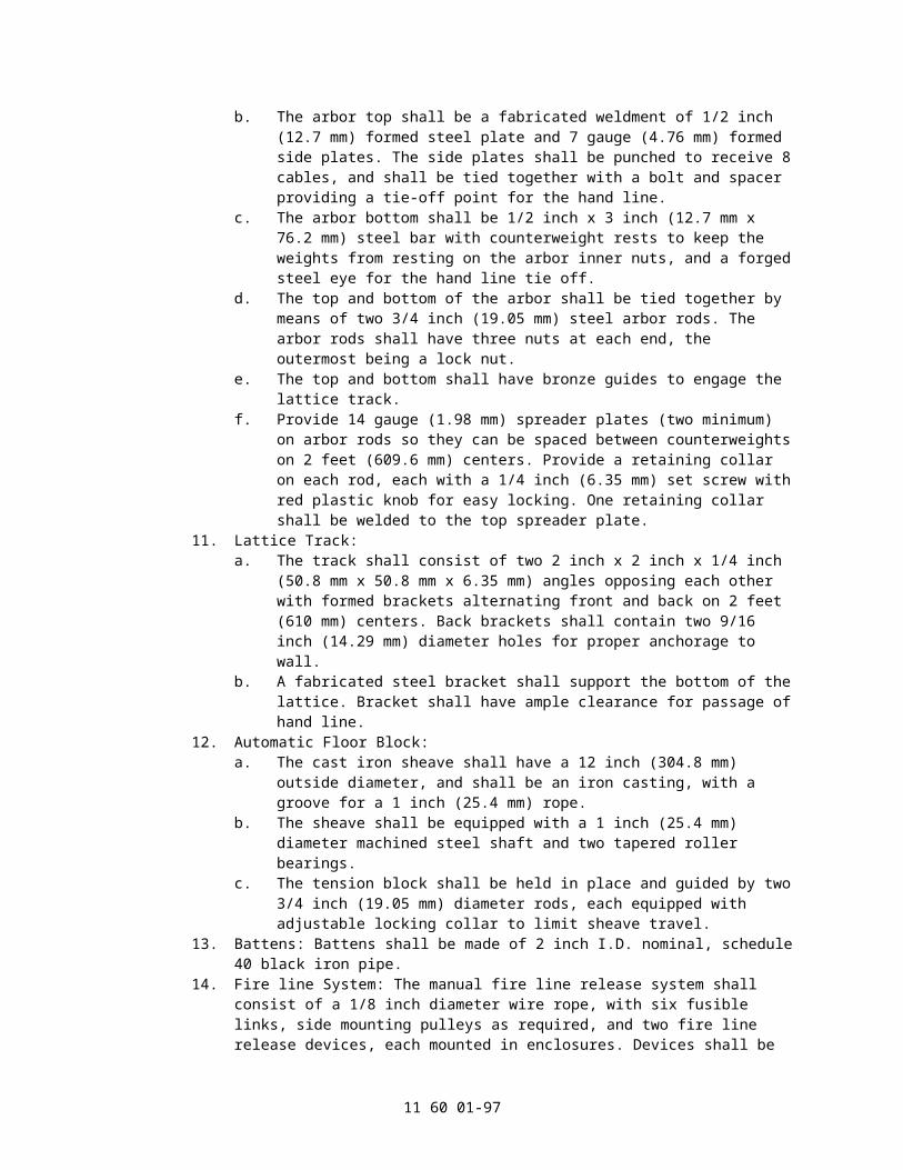
required by the governing code.5. Metal Edge Channel:
a. Fire curtain vertical edges shall have u-shaped, 16 gauge (1.6 mm) steel reinforcement 6 inch (152 mm) deep.
b. Channels shall attach to the curtain using the curtain guide bolts.c. Channels are supplied in 5 feet (1.5 m) and 10 feet (305 mm) long sections and
can be field cut.6. Smoke Pockets: Furnish and install one pair of smoke pockets to extend from the
stage floor to a point above the top of the raised curtain or to the height specified in the drawings. Pockets shall consist of a 6 inch deep "Z" channel formed from 1/4 inch (6.4 mm) steel plate and a 1/4 inch x 18 inch (6.4 mm x 457.2 mm) steel plate which shall be bolted to the channels on 2 feet-0 inch (609.6 mm) centers. A 14 ga. (1.98 mm) steel channel track, entirely enclosed except for a slot in the side, shall be bolted to the inside of each smoke pocket to carry the guide rollers. Channels shall be anchored to the walls on 4 feet-0 inch (1.2 m) centers.
7. Smoke Seal: Provide a smoke seal consisting of a triple layer of folded fabric fastened above the proscenium with a mounting clamp so it rubs the curtain and seals the top of the opening. The fabric shall be Zetex 800 cloth with a minimum weight of 27 oz. per square yard (0.91 KG/sq m).
8. Line Shaft Fire Curtain Hoist:a. The hoist shall consist of a gearmotor assembly, a drum for each lift line, and
interconnecting shafts. The gearmotor assembly shall include a brake release and a hydraulic speed regulator, allowing the curtain to close at a controlled rate of speed when the brake is released by the activation of the fire line. The hoist shall have a minimum1,400 lb (635 KG) lifting capacity at a rate of 25 feet per minute (0.127 m/s).
b. Gearmotor:1) The motor, primary brake and gearbox shall be an integrated unit, with
the first stage pinion gear and the primary brake both mounted directly on the motor's armature shaft. No couplings shall be permitted between the motor, primary brake and gear reducer.
2) Motors shall be totally enclosed fan cooled (TEFC). The motor shall have a minimum AGMA service factor of 1.0 for constant operation.
3) The gear reducer shall be a helical bevel reducer. The gear case shall be cast iron for protection against shock damage. The output shaft(s) shall have double lip oil seals to prevent leaks. The gearing service factor shall be a minimum of 1.0 with a mechanical strength service factor of 1.25.
4) Brakes shall be normally spring applied, direct acting, electrically released, and equipped with a manual release. The brake shall be an AC / DC electro-magnetic unit with a minimum retarding torque equal to 200 percent of motor full load torque.
c. Drums.1) Each helical drum shall be supported by a sturdy steel base, holding the
elements of the drum assembly in proper alignment. Both ends of each drum shall be supported by a self-aligning flange bearing.
2) Alternate drums shall be threaded in opposite directions, to keep the batten from "walking" as its elevation changes.
3) Drums shall be interconnected by shafts with universal joints at each end. Shafts without universal joints are not acceptable.
d. Rotary Limit Switches:1) Rotary limit switch assemblies shall have two or four independently
adjustable switch/cam sets as required. Cams shall be driven by a geared assembly.
2) Switches shall have snap acting contacts.3) Rotary limit switches shall be driven directly or by roller chains. If roller
chains are used, sprockets shall be pinned to prevent slipping and sized
11 60 01-97

for maximum usable rotation of switch cams. The input shaft and drive chain shall be fully guarded.
4) Switches shall be mounted to the hoist base to allow for easy adjustment of the switch settings.
e. Fixed Speed Starter:1) The traction drive hoist shall be controlled by a UL 508E listed, full
voltage, self protected, reversing starter. Enclosure shall be NEMA 12 with hinged, latching cover. The interior of the starter cabinet shall be "touch safe" per IEC 204-1 "Protection against direct contact" rules.
2) The NEMA/IEC, magnetically operated, mechanically and electrically interlocked, reversing starter shall be sized to match the hoist motor horsepower and shall be rated for plugging and jogging. Units shall incorporate UL508E Type 2, non-welding, positive break contactors.
3) Overcurrent protection shall be provided by an IEC Class 10 overload. Short circuit protection shall be provided by a circuit breaker.
4) Starters shall be wired so that operation of the normal end of travel limit switches shall only allow movement away from the limit switch. Operation of an overtravel limit switch shall open the line contactor, and shall not allow further movement in either direction. A spring return toggle switch shall be housed inside the starter cabinet to allow override of the overtravel limits for resetting purposes.
9. Control Stations: Two control stations shall be provided in wall mounted NEMA 12 enclosures. Each shall contain hold to operate (dead man) Up and Down pushbuttons, and a mushroom head emergency stop pushbutton.
10. Battens: Battens shall be made of 2 inch (50.8 mm) I.D. nominal, schedule 40 black iron pipe.
11. Fire line System: The manual fire line release system shall consist of a 1/8 inch (3.2 mm) diameter wire rope, with six fusible links, side mounting pulleys as required, and two fire line release devices, each mounted in a steel enclosure with acrylic viewing window that contains a positive method to release the fire line. Devices shall be mounted 5 feet (1,524 mm) above the stage floor on each side of the proscenium. All other components such as round weight arbors, arbor guards, floor pulleys, etc. required to form a fully functional fire line release system shall be provided.
12. Lift Cables: The curtain lift cables shall be 1/4 inch (6.4 mm) diameter 7x19 galvanized utility cable as specified. Cables shall be terminated with corresponding cable thimbles and two forged cable clips or a Swage sleeve fitting at each end. The curtain end of each cable shall be attached to the batten using a half pipe clamp.
13. Safety Chains: Supply one more safety chain than the number of lift cables. 1/4 inch (6.4 mm) minimum, proof coil chains shall be located between lift cables except at the ends where chains shall be 12 inch (304.8 mm) or less from the end of the batten. Chains shall be attached to the top of the curtain with pipe clamps around the top of the batten and chain shackles. The other end shall be appropriately attached to the building structure.
C. Traction Drive Hoist.1. General Description:
a. Furnish and install a motorized straight lift type, automatically closing fire safety curtain for the proscenium opening indicated on the drawings. Curtain shall lap masonry not less than 18 inch (457.2 mm) at each side of the proscenium opening and 24 inch (609.6 mm) at the top of the proscenium opening.
b. The curtain shall be arranged to comply with the "International Building Code (2006)", American National Standard E1.22-2009, other applicable codes and, in general, intercept fire and smoke and prevent glow from severe fire on the stage from showing on the auditorium side for at least thirty (30) minutes in order to permit safe egress of all people from the auditorium.
c. The curtain shall close by gravity due to over-balance of the curtain as specified
11 60 01-98
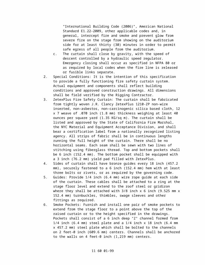
below. Emergency closing shall occur as specified in NFPA 80 or as required by local codes when the fire line is released or fusible links separate.
2. Special Conditions: It is the intention of this specification to provide a fully functioning fire safety curtain system. Actual equipment and components shall reflect building conditions and approved construction drawings. All dimensions shall be field verified by the Rigging Contractor.
3. ZetexPlus Fire Safety Curtain: The curtain shall be fabricated from tightly woven J.R. Clancy ZetexPlus 1210-ZP non-wire inserted, non-asbestos, non-carcinogenic silica based cloth, 12 x 7 weave of .070" (1.778 mm) thickness weighing at least 40 ounces per square yard (1.35 KG/sq m). The curtain shall be listed and approved by the State of California Fire Marshall, the NYC Material Acceptance and Equipment Acceptance Division, and shall bear a certification label from a nationally recognized listing agency. All strips of fabric shall be in continuous lengths running the full height of the curtain. There shall be no horizontal seams. Each seam shall be sewn with two lines of stitching using fiberglass thread. Top and bottom pockets shall be 6 inch (152.4 mm). The bottom pocket shall be equipped with a 3 inch (76.2 mm) yield pad filled with ZetexPlus.
4. Sides of curtain shall have steel wheel roller guides every 18 inch (457.2 mm), securely fastened to a 6 inch (152.4 mm) hem with at least three bolts or rivets, or as required by the governing code.
5. Metal Edge Channel:a. Fire curtain vertical edges shall have u-shaped, 16 gauge (1.6 mm) steel
reinforcement 6 inch (152 mm) deep.b. Channels shall attach to the curtain using the curtain guide bolts.c. Channels are supplied in 5 feet (1.5 m) and 10 feet (305 mm) long sections and
can be field cut.6. Smoke Pockets: Furnish and install one pair of smoke pockets to extend from the
stage floor to a point above the top of the raised curtain or to the height specified in the drawings. Pockets shall consist of a 6 inch deep "Z" channel formed from 1/4 inch (6.4 mm) steel plate and a 1/4 inch x 18 inch (6.4 mm x 457.2 mm) steel plate which shall be bolted to the channels on 2 feet-0 inch (609.6 mm) centers. A 14 ga. (1.98 mm) steel channel track, entirely enclosed except for a slot in the side, shall be bolted to the inside of each smoke pocket to carry the guide rollers. Channels shall be anchored to the walls on 4 feet-0 inch (1,219 mm) centers.
7. Smoke Seal: Provide a smoke seal consisting of a triple layer of folded fabric fastened above the proscenium with a mounting clamp so it rubs the curtain and seals the top of the opening. The fabric shall be Zetex 800 cloth with a minimum weight of 27 oz. per square yard (0.91 KG/sq m).
8. Traction Style Fire Curtain Hoist:a. The hoist shall consist of a traction sheave and a manual clutch with throw out
fork, direct coupled and keyed to the output shaft of the gearbox. The entire assembly shall be mounted on a heavy channel base. The hoist shall have a 2,000lb (907.2 KG) lifting capacity at a rate of 25 feet per minute (0.127 m/s).
b. The iron or steel sheave shall be a minimum diameter of 40 times cable diameter with V-grooves for the number and diameter of lift lines required.
c. The clutch shall be rated for the applied load. The clutch lever arm shall be kept engaged by tension in the fire line that passes through a pulley in the handle. Release of the clutch is ensured by an overbalance weight acting on the arm.
d. Gearmotor:1) The motor, primary brake and gearbox shall be an integrated unit, with
the first stage pinion gear and the primary brake both mounted directly on the motor's armature shaft. No couplings shall be permitted between the motor, primary brake and gear reducer.
2) Motor shall be totally enclosed fan cooled (TEFC). The motor shall have a minimum AGMA service factor of 1.0 for constant operation.
3) The gear reducer shall be a combination helical/bevel reducer. The gear
11 60 01-99

case shall be cast iron for protection against shock damage. The output shaft(s) shall have double lip oil seals to prevent leaks. The gearing service factor shall be a minimum of 1.0 with a mechanical strength service factor of 1.25.
4) Brakes shall be normally spring applied, direct acting, electrically released, and equipped with a manual release. The brake shall be an AC / DC electro-magnetic unit with a minimum retarding torque equal to 200 percent of motor full load torque.
e. Four direct struck limit switches shall be installed so that they are operated by the fire curtain arbor. These shall provide top and bottom limits of travel as well as overtravel functions. The direct struck limit switches shall be heavy duty, lever operated rotary head units, with positive opening contacts. Direct struck limit switches shall be Telemecanique ZCKJ series or equal.
f. Fixed Speed Starter:1) The traction drive hoist shall be controlled by a UL 508E listed, full
voltage, self protected, reversing starter. Enclosure shall be NEMA 12 with hinged, latching cover. The interior of the starter cabinet shall be "touch safe" per IEC 204-1 "Protection against direct contact" rules.
2) The NEMA/IEC, magnetically operated, mechanically and electrically interlocked, reversing starter shall be sized to match the hoist motor horsepower and shall be rated for plugging and jogging. Units shall incorporate UL508E Type 2, non-welding, positive break contactors.
3) Overcurrent protection shall be provided by an IEC Class 10 overload. Short circuit protection shall be provided by a circuit breaker.
4) Starters shall be wired so that operation of the normal end of travel limit switches shall only allow movement away from the limit switch. Operation of an overtravel limit switch shall open the line contactor, and shall not allow further movement in either direction. A spring return toggle switch shall be housed inside the starter cabinet to allow override of the overtravel limits for resetting purposes.
9. Control Stations: Two control stations shall be provided in wall mounted NEMA 12 enclosures. Each shall contain hold to operate (dead man) Up and Down pushbuttons, and a mushroom head emergency stop pushbutton.
10. Loft Block:a. The sheave shall have a 12 inch (304.8 mm) pitch diameter, and shall be an
iron casting, with a machined groove. The sheave shall be equipped with a 1 inch (25.4 mm) diameter shaft and two tapered roller bearings.
b. Base angles shall be a minimum 2 inch x 1-1/2 inch x 1/4 inch (50.8 mm x 38.1 mm x 6.4 mm) angle.
c. Side plates shall be a minimum of 10-gauge (3.57 mm) steel, and shall fully enclose the sheave. Side plates shall be bolted to the base angles.
d. The block and associated mounting hardware shall have a recommended working load of at least 1400 lbs (635 KG), and shall be designed for use in either upright or underhung usage.
e. Loft blocks shall have cast iron sheave grooved for one 3/8 inch (9.5 mm) lift line.
11. Counterweight Arbor:a. Arbor shall be long enough to accommodate counterweights to balance the fire
curtain and related equipment.b. The arbor top shall be a fabricated weldment of 1/2 inch (12.7 mm) formed
steel plate and 7 gauge (4.76 mm) formed side plates. The side plates shall be punched to receive 8 cables, and shall be tied together with a bolt and spacer providing a tie-off point for the hand line.
c. The arbor bottom shall be 1/2 inch x 3 inch (12.7 mm x 76.2 mm) steel bar with counterweight rests to keep the weights from resting on the arbor inner nuts, and a forged steel eye for the hand line tie off.
11 60 01-100

d. The top and bottom of the arbor shall be tied together by means of two 3/4 inch (19.1 mm) steel arbor rods. The arbor rods shall have three nuts at each end, the outermost being a lock nut.
e. The top and bottom shall have bronze guides to engage the lattice track.f. Provide 14 gauge (1.98 mm) spreader plates (two minimum) on arbor rods so
they can be spaced between counterweights on 2 feet (609.6 mm) centers. Provide a retaining collar on each rod, each with a 1/4 inch (6.4 mm) set screw with red plastic knob for easy locking. One retaining collar shall be welded to the top spreader plate.
12. Lattice Track:a. The track shall consist of two 2 inch x 2 inch x 1/4 inch (50.8 mm x 50.8 mm x
6.4 mm) angles opposing each other with formed brackets alternating front and back on 2 feet centers. Back brackets shall contain two 9/16 inch (14.3 mm) diameter holes for proper anchorage to wall.
b. A fabricated steel bracket shall support the bottom of the lattice. Bracket shall have ample clearance for passage of hand line.
13. Battens: Battens shall be made of 2 inch (50.8 mm) I.D. nominal, schedule 40 black iron pipe.
14. Fire line System: The manual fire line release system shall consist of a 1/8 inch (3.2 mm) diameter wire rope, with six fusible links, side mounting pulleys as required, and two fire line release devices, each mounted in enclosures. Devices shall be mounted 5 feet (1,524 mm) above the stage floor on each side of the proscenium. All other components such as round weight arbors, arbor guards, floor pulleys, etc. required to form a fully functional fire line release system shall be provided.
15. Lift Cables: The curtain lift cables shall be 3/8 inch (9.5 mm) diameter 7 x 19 galvanized utility cable as specified. Cables shall be terminated with corresponding cable thimbles and two forged cable clips or a Swage sleeve fitting at each end. The curtain end of each cable shall be attached to the batten using pipe clamp.
16. Safety Chains: Supply one more safety chain than the number of lift cables. 1/4 inch (6.4 mm) minimum, proof coil chains shall be located between lift cables except at the ends where chains shall be 12 inch (304.8 mm) or less from the end of the batten. Chains shall be attached to the top of the curtain with pipe clamps around the top of the batten and chain shackles. The other end shall be appropriately attached to the building structure.
D. Drum Hoist.1. General Description:
a. Furnish and install a motorized straight lift type, automatically closing fire safety curtain for the proscenium opening indicated on the drawings. Curtain shall lap masonry not less than 18 inch (457.2 mm) at each side of the proscenium opening and 24 inch (609.6 mm) at the top of the proscenium opening.
b. The curtain shall be arranged to comply with the "International Building Code (2006)", American National Standard E1.22-2009, other applicable codes and, in general, intercept fire and smoke and prevent glow from severe fire on the stage from showing on the auditorium side for at least thirty (30) minutes in order to permit safe egress of all people from the auditorium.
c. The curtain shall close by gravity due to over-balance of the curtain as specified below. Emergency closing shall occur as specified in NFPA 80 or as required by local codes when the fire line is released or fusible links separate.
2. Special Conditions: It is the intention of this specification to provide a fully functioning fire safety curtain system. Actual equipment and components shall reflect building conditions and approved construction drawings. All dimensions shall be field verified by the Rigging Contractor.
3. ZetexPlus Fire Safety Curtain: The curtain shall be fabricated from tightly woven J.R. Clancy ZetexPlus 1210-ZP non-wire inserted, non-asbestos, non-carcinogenic silica based cloth, 12 x 7 weave of .070 inch (1.778 mm) thickness weighing at least 40
11 60 01-101

ounces per square yard (1.35 KG/sq m). The curtain shall be listed and approved by the State of California Fire Marshall, the NYC Material Acceptance and Equipment Acceptance Division, and shall bear a certification label from a nationally recognized listing agency. All strips of fabric shall be in continuous lengths running the full height of the curtain. There shall be no horizontal seams. Each seam shall be sewn with two lines of stitching using fiberglass thread. Top and bottom pockets shall be 6 inch (152.4 mm). The bottom pocket shall be equipped with a 3 inch (76.2 mm) yield pad filled with ZetexPlus.
4. Sides of curtain shall have steel wheel roller guides every 18 inch (457.2 mm), securely fastened to a 6 inch (152.4 mm) hem with at least three bolts or rivets, or as required by the governing code.
5. Metal Edge Channel:a. Fire curtain vertical edges shall have u-shaped, 16 gauge (1.6 mm) steel
reinforcement 6 inch (152 mm) deep.b. Channels shall attach to the curtain using the curtain guide bolts.c. Channels are supplied in 5 feet (1.5 m) and 10 feet (305 mm) long sections and
can be field cut.6. Smoke Pockets: Furnish and install one pair of smoke pockets to extend from the
stage floor to a point above the top of the raised curtain or to the height specified in the drawings. Pockets shall consist of a 6 inch deep "Z" channel formed from 1/4 inch (6.4 mm) steel plate and a 1/4 inch x 18 inch (6.4 mm x 457.2 mm) steel plate which shall be bolted to the channels on 2 feet-0 inch (609.6 mm) centers. A 14 ga. (1.98 mm) steel channel track, entirely enclosed except for a slot in the side, shall be bolted to the inside of each smoke pocket to carry the guide rollers. Channels shall be anchored to the walls on 4 feet-0 inch (1,219 mm) centers.
7. Smoke Seal: Provide a smoke seal consisting of a triple layer of folded fabric fastened above the proscenium with a mounting clamp so it rubs the curtain and seals the top of the opening. The fabric shall be Zetex 800 cloth with a minimum weight of 27 oz. per square yard (0.91 KG/sq m).
8. Drum Style Fire Curtain Hoist:a. The hoist shall be mounted to allow dual drive lines to travel from either side of
the fire curtain centerline, over loft blocks and to the hoist drum.b. The hoist shall consist of a cable drum and a manual clutch with throw out fork,
direct coupled and keyed to the output shaft of the gearbox. The entire assembly shall be mounted on a heavy channel base. The hoist shall have a 2,000lb (907.2 KG) lifting capacity at a rate of 25 feet per minute (0.127 m/s).
c. The drum shall be a minimum diameter of 30 times cable diameter with helical grooves for the number and diameter of lift lines required.
d. The clutch shall be rated for the applied load. The clutch lever arm shall be kept engaged by tension in the fire line that passes through a pulley in the handle. Release of the clutch is ensured by an overbalance weight acting on the arm.
e. Gearmotor:1) The motor, primary brake and gearbox shall be an integrated unit, with
the first stage pinion gear and the primary brake both mounted directly on the motor's armature shaft. No couplings shall be permitted between the motor, primary brake and gear reducer.
2) Motor shall be totally enclosed fan cooled (TEFC). The motor shall have a minimum AGMA service factor of 1.0 for constant operation.
3) The gear reducer shall be a combination helical/bevel reducer. The gear case shall be cast iron for protection against shock damage. The output shaft(s) shall have double lip oil seals to prevent leaks. The gearing service factor shall be a minimum of 1.0 with a mechanical strength service factor of 1.25.
4) Brakes shall be normally spring applied, direct acting, electrically released, and equipped with a manual release. The brake shall be an AC / DC electro-magnetic unit with a minimum retarding torque equal to 200
11 60 01-102

percent of motor full load torque.f. Four direct struck limit switches shall be installed so that they are operated by
the fire curtain arbor. These shall provide top and bottom limits of travel as well as overtravel functions. The direct struck limit switches shall be heavy duty, lever operated rotary head units, with positive opening contacts. Direct struck limit switches shall be Telemecanique ZCKJ series or equal.
g. Fixed Speed Starter:1) The hoist shall be controlled by a UL 508E listed, full voltage, self
protected, reversing starter. Enclosure shall be NEMA 12 with hinged, latching cover. The interior of the starter cabinet shall be "touch safe" per IEC 204-1 "Protection against direct contact" rules.
2) The NEMA/IEC, magnetically operated, mechanically and electrically interlocked, reversing starter shall be sized to match the hoist motor horsepower and shall be rated for plugging and jogging. Units shall incorporate UL508E Type 2, non-welding, positive break contactors.
3) Overcurrent protection shall be provided by an IEC Class 10 overload. Short circuit protection shall be provided by a circuit breaker.
4) Starters shall be wired so that operation of the normal end of travel limit switches shall only allow movement away from the limit switch. Operation of an overtravel limit switch shall open the line contactor, and shall not allow further movement in either direction. A spring return toggle switch shall be housed inside the starter cabinet to allow override of the overtravel limits for resetting purposes.
9. Control Stations: Two control stations shall be provided in wall mounted NEMA 12 enclosures. Each shall contain hold to operate (dead man) Up and Down pushbuttons, and a mushroom head emergency stop pushbutton.
10. Loft Block:a. The sheave shall have a 12 inch (304.8 mm) pitch diameter, and shall be an
iron casting, with a machined groove. The sheave shall be equipped with a 1 inch (25.4 mm) diameter shaft and two tapered roller bearings.
b. Base angles shall be a minimum 2 inch x 1-1/2 inch x 1/4 inch (50.8 mm x 38.1 mm x 6.4 mm) angle.
c. Side plates shall be a minimum of 10-gauge (3.57 mm) steel, and shall fully enclose the sheave. Side plates shall be bolted to the base angles.
d. The block and associated mounting hardware shall have a recommended working load of at least 1400 lbs (635 KG), and shall be designed for use in either upright or underhung usage.
e. Loft blocks shall have cast iron sheave grooved for one 3/8 inch (9.5 mm) lift line.
11. Counterweight Arbor:a. Arbor shall be long enough to accommodate counterweights to permit normal
motorized operation of the fire curtain and emergency closure without power.b. The arbor top shall be a fabricated weldment of 1/2 inch (12.7 mm) formed
steel plate and 7 gauge (4.76 mm) formed side plates. The side plates shall be punched to receive 8 cables, and shall be tied together with a bolt and spacer providing a tie-off point for the hand line.
c. The arbor bottom shall be 1/2 inch x 3 inch (12.7 mm x 76.2 mm) steel bar with counterweight rests to keep the weights from resting on the arbor inner nuts, and a forged steel eye for the hand line tie off.
d. The top and bottom of the arbor shall be tied together by means of two 3/4 inch (19.1 mm) steel arbor rods. The arbor rods shall have three nuts at each end, the outermost being a lock nut.
e. The top and bottom shall have bronze guides to engage the lattice track.f. Provide 14 gauge (1.98 mm) spreader plates (two minimum) on arbor rods so
they can be spaced between counterweights on 2 feet (609.6 mm) centers. Provide a retaining collar on each rod, each with a 1/4 inch (6.4 mm) set screw
11 60 01-103

with red plastic knob for easy locking. One retaining collar shall be welded to the top spreader plate.
12. Lattice Track:a. The track shall consist of two 2 inch x 2 inch x 1/4 inch (50.8 mm x 50.8 mm x
6.4 mm) angles opposing each other with formed brackets alternating front and back on 2 feet centers. Back brackets shall contain two 9/16 inch (14.3 mm) diameter holes for proper anchorage to wall.
b. A fabricated steel bracket shall support the bottom of the lattice. Bracket shall have ample clearance for passage of hand line.
13. Battens: Battens shall be made of 2 inch (50.8 mm) I.D. nominal, schedule 40 black iron pipe.
14. Fire line System: The manual fire line release system shall consist of a 1/8 inch (3.2 mm) diameter wire rope, with six fusible links, side mounting pulleys as required, and two fire line release devices, each mounted in enclosures. Devices shall be mounted 5 feet (1,524 mm) above the stage floor on each side of the proscenium. All other components such as round weight arbors, arbor guards, floor pulleys, etc. required to form a fully functional fire line release system shall be provided.
15. Lift Cables: The curtain lift cables shall be 3/8 inch (9.5 mm) diameter 7 x 19 galvanized utility cable as specified. Cables shall be terminated with corresponding cable thimbles and two forged cable clips or a Swage sleeve fitting at each end. The curtain end of each cable shall be attached to the batten using a pipe clamp.
16. Safety Chains: Supply one more safety chain than the number of lift cables. 1/4 inch (6.4 mm) minimum, proof coil chains shall be located between lift cables except at the ends where chains shall be 12 inch (304.8 mm) or less from the end of the batten. Chains shall be attached to the top of the curtain with pipe clamps around the top of the batten and chain shackles. The other end shall be appropriately attached to the building structure.
2.30 FIRE CURTAIN SYSTEMS, STRAIGHT LIFT CURTAIN, PROSCENIUM OPENING GREATER THAN 30'T x 50'W
A. Line Shaft Hoist:1. General Description:
a. Furnish and install a motorized straight lift type, automatically closing fire safety curtain for the proscenium opening indicated on the drawings. Curtain shall lap masonry not less than 18 inch (457 mm) at each side of the proscenium opening and 24 inch (610 mm) at the top of the proscenium opening.
b. The curtain shall be arranged to comply with the "International Building Code (2006)", American National Standard E1.22-2009, other applicable codes and, in general, intercept fire and smoke and prevent glow from severe fire on the stage from showing on the auditorium side for at least thirty (30) minutes in order to permit safe egress of all people from the auditorium.
c. The curtain shall close by gravity due to over-balance of the curtain as specified below. Emergency closing shall occur as specified in NFPA 80 or as required by local codes when the fire line is released or fusible links separate.
2. Special Conditions: It is the intention of this specification to provide a fully functioning fire safety curtain system. Actual equipment and components shall reflect building conditions and approved construction drawings. All dimensions shall be field verified by the Rigging Contractor.
3. ZetexPlus Fire Safety Curtain: The curtain shall be fabricated from tightly woven J.R. Clancy ZetexPlus 1210-ZP non-wire inserted, non-asbestos, non-carcinogenic silica based cloth, 12 x 7 weave of .070 inch (1.8 mm) thickness weighing at least 40 ounces per square yard (1.35 KG/sq m). The curtain shall be listed and approved by the State of California Fire Marshall, the NYC Material Acceptance and Equipment Acceptance Division, and shall bear a certification label from a nationally recognized listing agency. All strips of fabric shall be in continuous lengths running the full height
11 60 01-104
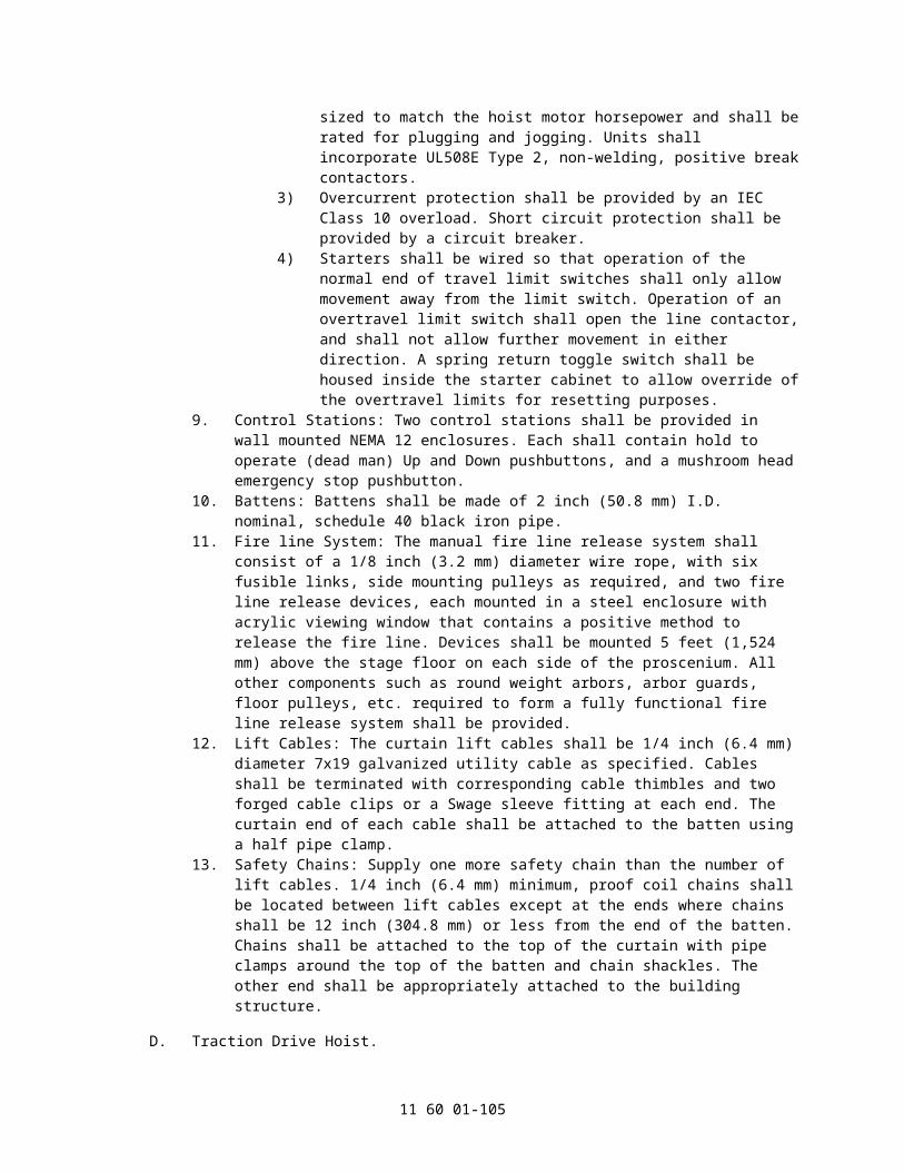
of the curtain. There shall be no horizontal seams. Each seam shall be sewn with two lines of stitching using fiberglass thread. Top and bottom pockets shall be 6 inch (152.4 mm). The bottom pocket shall be equipped with a 6 inch (152.4 mm) yield pad filled with ZetexPlus.
4. Fire Safety Curtain Frame: The fully framed fire safety curtain shall be designed and fabricated to sustain a minimum uniform wind load of 2 psf, or as indicated by code. The attachment of the curtain to the frame shall be made to facilitate future maintenance and repair. The frame shall remain engaged in its guides and operate under the full range of temperatures and wind conditions.
5. Each side of the curtain frame shall have two bronze guides, securely fastened to the curtain frame.
6. Smoke Seal: Provide a smoke seal consisting of a triple layer of folded fabric fastened above the proscenium with a mounting clamp so it rubs the curtain and seals the top of the opening. The fabric shall be Zetex 800 cloth with a minimum weight of 27 oz/yd² (0.91 KG/sq m).
7. Line Shaft Fire Curtain Hoist:a. The hoist shall consist of a gearmotor assembly, a drum for each lift line, and
interconnecting shafts. The gearmotor assembly shall include a brake release and a hydraulic speed regulator, allowing the curtain to close at a controlled rate of speed when the brake is released by the activation of the fire line. The hoist shall have a minimum 1,400lb. (635 KG) lifting capacity at a rate of 25 feet/min (0.127 m/s).
b. Gearmotor:1) The motor, primary brake and gearbox shall be an integrated unit, with
the first stage pinion gear and the primary brake both mounted directly on the motor's armature shaft. No couplings shall be permitted between the motor, primary brake and gear reducer.
2) Motors shall be totally enclosed fan cooled (TEFC). The motor shall have a minimum AGMA service factor of 1.0 for constant operation.
3) The gear reducer shall be a helical bevel reducer. The gear case shall be cast iron for protection against shock damage. The output shaft(s) shall have double lip oil seals to prevent leaks. The gearing service factor shall be a minimum of 1.0 with a mechanical strength service factor of 1.25.
4) Brakes shall be normally spring applied, direct acting, electrically released, and equipped with a manual release. The brake shall be an AC / DC electro-magnetic unit with a minimum retarding torque equal to 200 percent of motor full load torque.
c. Drums.1) Each helical drum shall be supported by a sturdy steel base, holding the
elements of the drum assembly in proper alignment. Both ends of each drum shall be supported by a self-aligning flange bearing.
2) Alternate drums shall be threaded in opposite directions, to keep the batten from "walking" as its elevation changes.
3) Drums shall be interconnected by shafts with universal joints at each end. Shafts without universal joints are not acceptable.
d. Rotary Limit Switches:1) Rotary limit switch assemblies shall have two or four independently
adjustable switch/cam sets as required. Cams shall be driven by a geared assembly.
2) Switches shall have snap acting contacts.3) Rotary limit switches shall be driven directly or by roller chains. If roller
chains are used, sprockets shall be pinned to prevent slipping and sized for maximum usable rotation of switch cams. The input shaft and drive chain shall be fully guarded.
4) Switches shall be mounted to the hoist base to allow for easy adjustment of the switch settings.
11 60 01-105

e. Fixed Speed Starter:1) The hoist shall be controlled by a UL 508E listed, full voltage, self-
protected, reversing starter. Enclosure shall be NEMA 12 with hinged, latching cover. The interior of the starter cabinet shall be "touch safe" per IEC 204-1 "Protection against direct contact" rules.
2) The NEMA/IEC, magnetically operated, mechanically and electrically interlocked, reversing starter shall be sized to match the hoist motor horsepower and shall be rated for plugging and jogging. Units shall incorporate UL508E Type 2, non-welding, positive break contactors.
3) Overcurrent protection shall be provided by an IEC Class 10 overload. Short circuit protection shall be provided by a circuit breaker.
4) Starters shall be wired so that operation of the normal end of travel limit switches shall only allow movement away from the limit switch. Operation of an overtravel limit switch shall open the line contactor, and shall not allow further movement in either direction. A spring return toggle switch shall be housed inside the starter cabinet to allow override of the overtravel limits for resetting purposes.
8. Control Stations: Two control stations shall be provided in wall mounted NEMA 12 enclosures. Each shall contain hold to operate (dead man) Up and Down pushbuttons, and a mushroom head emergency stop pushbutton.
9. Fire line System: The manual fire line release system shall consist of a 1/8 inch (3.2 mm) diameter wire rope, with six UL listed fusible links that release at 165 degree F (74 degree C), side mounting pulleys as required, and two fire line release devices, each mounted in a steel enclosure with acrylic viewing window that contains a positive method to release the fire line. Devices shall be mounted 5 feet-0 inch (1,524 mm) above the stage floor on each side of the proscenium. All other components such as round weight arbors, arbor guards, floor pulleys, etc. required to form a fully functional fire line release system shall be provided.
10. Lift Cables: The curtain lift cables shall be 3/8 inch (9.5 mm) diameter 7 x 19 galvanized utility cable as specified. Cables shall be terminated with corresponding cable thimbles and two forged cable clips or a Swage sleeve fitting at each end. The curtain end of each cable shall be attached to the batten using a pipe clamp.
11. Battens: Battens shall be made of 2 inch (50.8 mm) I.D. nominal, schedule 40 black iron pipe.
12. Safety Chains: Supply one more safety chain than the number of lift cables. 1/4 inch (6.4 mm) minimum, proof coil chains shall be located between lift cables except at the ends where the chains shall be 12 inch (304.8 mm) or less from the end of the batten. Chains shall be attached to the top of the curtain with pipe clamps around the top of the batten and chain shackles. The other end shall be appropriately attached to the building structure.
13. Smoke Pockets with Track: Furnish and install one pair of smoke pockets to extend from the stage floor to a point above the top of the raised curtain or to the height specified in the drawings. Pockets shall consist of an 8 inch (203 mm) deep "Z" channel formed from 1/4 inch (6.4 mm) steel plate and a 1/4 inch x 18 inch (6.4 mm x 457 mm) steel plate which shall be bolted to the channels on 2 feet-0 inch (610 mm) centers. An angle iron, steel track shall be bolted to the side of the smoke pocket to carry the guides. Channels shall be anchored to the walls on 4 feet-0 inch (1,219 mm) centers.
B. Traction Drive Hoist.1. General Description:
a. Furnish and install a motorized straight lift type, automatically closing fire safety curtain for the proscenium opening indicated on the drawings. Curtain shall lap masonry not less than 18 inch 457 mm) at each side of the proscenium opening and 24 inch (610 mm) at the top of the proscenium opening.
b. The curtain shall be arranged to comply with the International Building Code
11 60 01-106

(2015), NFPA 80: Standard for Fire Doors and Other Opening Protectives, other applicable codes and, in general, intercept fire and smoke and prevent glow from severe fire on the stage from showing on the auditorium side for at least thirty (30) minutes in order to permit safe egress of all people from the auditorium.
c. The curtain shall close by gravity due to over-balance of the curtain as specified below. When the fire line is released, emergency closing shall occur at an average speed between 6 in/sec (152 mm/sec) and 24 in/sec (610 mm/sec) with the last 8 feet (2.4 m) taking more than 5 seconds.
2. Special Conditions: It is the intention of this specification to provide a fully functioning fire safety curtain system. Actual equipment and components shall reflect building conditions and approved construction drawings. All dimensions shall be field verified by the Rigging Contractor.
3. ZetexPlus Fire Safety Curtain: The curtain shall be fabricated from tightly woven J.R. Clancy ZetexPlus 1210-ZP non-wire inserted, non-asbestos, non-carcinogenic silica based cloth, 12 x 7 weave of .070 inch (1.8 mm) thickness weighing at least 40 ounces per square yard (1.35 KG/sq m). The curtain shall be listed and approved by the State of California Fire Marshall, the NYC Material Acceptance and Equipment Acceptance Division, and shall bear a certification label from a nationally recognized listing agency. All strips of fabric shall be in continuous lengths running the full height of the curtain. There shall be no horizontal seams. Each seam shall be sewn with two lines of stitching using fiberglass thread. Top and bottom pockets shall be 6 inch (152.4 mm). The bottom pocket shall be equipped with a 6 inch (152.4 mm) yield pad filled with ZetexPlus.
4. Fire Safety Curtain Frame: The fully framed fire safety curtain shall be designed and fabricated to sustain a minimum uniform wind load of 2 psf, or as indicated by code. The attachment of the curtain to the frame shall be made to facilitate future maintenance and repair. The frame shall remain engaged in its guides and operate under the full range of temperatures and wind conditions.
5. Each side of the curtain frame shall have two bronze guides, securely fastened to the curtain frame.
6. Smoke Seal: Provide a smoke seal consisting of a triple layer of folded fabric fastened above the proscenium with a mounting clamp so it rubs the curtain and seals the top of the opening. The fabric shall be Zetex 800 cloth with a minimum weight of 27 oz. per square yard (0.91 KG/sq m).
7. Traction Style Fire Curtain Hoist:a. The hoist shall consist of a traction sheave and gearmotor assembly. The
gearmotor assembly shall consist of a high efficiency gearbox, brake release and hydraulic speed regulator, allowing the curtain to close at a controlled rate of speed when the brake is released. The entire assembly shall be mounted on a heavy channel base. The hoist shall have a lifting capacity sufficient to overcome the out of balance load required to lower the curtain at a rate of 25 feet per minute (0.13 m/s).
b. The sheave shall be a 20 inch (508 mm) diameter iron or steel sheave, with V-grooves for the number and diameter of lift lines required.
c. Gearmotor:1) The motor, primary brake and gearbox shall be an integrated unit, with
the first stage pinion gear and the primary brake both mounted directly on the motor's armature shaft. No couplings shall be permitted between the motor, primary brake and gear reducer.
2) Motors shall be totally enclosed fan cooled (TEFC). The motor shall have a minimum AGMA service factor of 1.0 for constant operation.
3) The gear reducer shall be a helical bevel reducer. The gear case shall be cast iron for protection against shock damage. The output shaft(s) shall have double lip oil seals to prevent leaks. The gearing service factor shall be a minimum of 1.0 with a mechanical strength service factor of 1.25.
11 60 01-107

4) Brakes shall be normally spring applied, direct acting, electrically released, and equipped with a manual release. The brake shall be an AC / DC electro-magnetic unit with a minimum retarding torque equal to 200 percent of motor full load torque.
d. Four direct struck limit switches shall be installed so that they are operated by the fire curtain arbor. These shall provide top and bottom limits of travel as well as overtravel functions. The direct struck limit switches shall be heavy duty, lever operated rotary head units, with positive opening contacts. Direct struck limit switches shall be Allen Bradley Bulletin 802T or equal.
e. Fixed Speed Starter:1) The traction drive hoist shall be controlled by a UL 508E listed, full
voltage, self protected, reversing starter. Enclosure shall be NEMA 12 with hinged, latching cover. The interior of the starter cabinet shall be "touch safe" per IEC 204-1 "Protection against direct contact" rules.
2) The NEMA/IEC, magnetically operated, mechanically and electrically interlocked, reversing starter shall be sized to match the hoist motor horsepower and shall be rated for plugging and jogging. Units shall incorporate UL508E Type 2, non-welding, positive break contactors.
3) Overcurrent protection shall be provided by an IEC Class 10 overload. Short circuit protection shall be provided by a circuit breaker.
4) Starters shall be wired so that operation of the normal end of travel limit switches shall only allow movement away from the limit switch. Operation of an overtravel limit switch shall open the line contactor, and shall not allow further movement in either direction. A spring return toggle switch shall be housed inside the starter cabinet to allow override of the overtravel limits for resetting purposes.
8. Control Stations: Two control stations shall be provided in wall mounted NEMA 12 enclosures. Each shall contain hold to operate (dead man) Up and Down pushbuttons, and a mushroom head emergency stop pushbutton.
9. Loft Block:a. The sheave shall have a 16 inch (406.4 mm) pitch diameter, and shall be an
iron casting, with a machined groove. The sheave shall be equipped with a 1 inch (25.4 mm) diameter shaft and two tapered roller bearings.
b. Base angles shall be a minimum 2 inch x 1-1/2 inch x 1/4 inch (50.8 mm x 38.1 mm x 6.4 mm) angle.
c. Side plates shall be a minimum of 10-gauge (3.57 mm) steel, and shall fully enclose the sheave. Side plates shall be bolted to the base angles.
d. The block and associated mounting hardware shall have a recommended working load of at least 1,400lb (635 KG), and shall be designed for use in either upright or underhung usage.
e. Loft blocks shall have a cast iron sheave grooved for one 3/8 inch (9.5 mm) lift line.
10. Counterweight Arbor:a. Arbor shall be long enough to accommodate counterweights to balance the fire
curtain and related equipment.b. The arbor top shall be a fabricated weldment of 1/2 inch (12.7 mm) formed
steel plate and 7 gauge (4.76 mm) formed side plates. The side plates shall be punched to receive 8 cables, and shall be tied together with a bolt and spacer providing a tie-off point for the hand line.
c. The arbor bottom shall be 1/2 inch x 3 inch (12.7 mm x 76.2 mm) steel bar with counterweight rests to keep the weights from resting on the arbor inner nuts, and a forged steel eye for the hand line tie off.
d. The top and bottom of the arbor shall be tied together by means of two 3/4 inch (19.1 mm) steel arbor rods. The arbor rods shall have three nuts at each end, the outermost being a lock nut.
e. The top and bottom shall have bronze guides to engage the lattice track.
11 60 01-108

f. Provide 14 gauge (1.98 mm) spreader plates (two minimum) on arbor rods so they can be spaced between counterweights on 2 feet (610 mm) centers. Provide a retaining collar on each rod, each with a 1/4 inch (6.4 mm) set screw with red plastic knob for easy locking. One retaining collar shall be welded to the top spreader plate.
11. Lattice Track:a. The track shall consist of two 2 inch x 2 inch x 1/4 inch (50.8 mm x 50.8 mm x
6.4 mm) angles opposing each other with formed brackets alternating front and back on 2 feet centers. Back brackets shall contain two 9/16 inch (14.3 mm) diameter holes for proper anchorage to the wall.
b. A fabricated steel bracket shall support the bottom of the lattice. Bracket shall have ample clearance for passage of hand line.
12. Fire line System: The manual fire line release system shall consist of a 1/8 inch (3.2 mm) diameter wire rope, UL listed fusible links that release at 165 degree F (74 degree C), side mounting pulleys as required, and two fire line release devices, each mounted in a steel enclosure with acrylic viewing window that contains a positive method to release the fire line. Devices shall be mounted 5 feet (1,524 mm) above the stage floor on each side of the proscenium. All other components such as round weight arbors, arbor guards, floor pulleys, etc. required to form a fully functional fire line release system shall be provided.a. Fusible links shall be spaced every 15 feet (4.6 m) along the length of the fire
line. A fusible link shall be located no more than 7.5 feet (2.3 m) from the vertical rise of the fire line.
13. Lift Cables: The curtain lift cables shall be 3/8 inch (9.5 mm) diameter 7 x 19 galvanized utility cable as specified. Cables shall be terminated with corresponding cable thimbles and two forged cable clips or a Swage sleeve fitting at each end. The curtain end of each cable shall be attached to the batten using a pipe clamp.
14. Battens: Battens shall be made of 2 inch (50.8 mm) I.D. nominal, schedule 40 black iron pipe.
15. Safety Chains: Supply one more safety chain than the number of lift cables. 1/4 inch (6.4 mm) minimum, proof coil chains shall be located between lift cables except at the ends where the chains shall be 12 inch (304.8 mm) or less from the end of the batten. Chains shall be attached to the top of the curtain with pipe clamps around the top of the batten and chain shackles. The other end shall be appropriately attached to the building structure.
16. Smoke Pockets with Track: Furnish and install one pair of smoke pockets to extend from the stage floor to a point above the top of the raised curtain or to the height specified in the drawings. Pockets shall consist of a channel 4 inch (102 mm) deeper than the curtain frame and a 1/4 inch x 18 inch (6.4 mm x 457.2 mm) steel plate which shall be bolted to the channels on 2 feet-0 inch (609.6 mm) centers. An angle steel track shall be bolted to the side of the smoke pocket to carry the guides. Channels shall be anchored to the walls on 4 feet-0 inch (1,219 mm) centers or as required to support the curtain.
C. Drum Hoist.1. General Description:
a. Furnish and install a motorized framed type, automatically closing fire safety curtain for the proscenium opening indicated on the drawings. Curtain shall lap masonry not less than 18 inch (457 mm) at each side of the proscenium opening and 24 inch (610 mm) at the top of the proscenium opening.
b. The curtain shall be arranged to comply with the "International Building code (2006)", American National Standard E1.22-2009, other applicable codes and, in general, intercept fire and smoke and prevent glow from severe fire on the stage from showing on the auditorium side for at least thirty (30) minutes in order to permit safe egress of all people from the auditorium.
c. The curtain shall close by gravity due to over-balance of the curtain as specified
11 60 01-109

below. Emergency closing shall occur as specified in NFPA 80 or as required by local codes when the fire line is released or fusible links separate.
2. Special Conditions: It is the intention of this specification to provide a fully functioning fire safety curtain system. Actual equipment and components shall reflect building conditions and approved construction drawings. All dimensions shall be field verified by the Rigging Contractor.
3. ZetexPlus Fire Safety Curtain: The curtain shall be fabricated from tightly woven J.R. Clancy ZetexPlus 1210-ZP non-wire inserted, non-asbestos, non-carcinogenic silica based cloth, 12 x 7 weave of .070 inch (1.8 mm) thickness weighing at least 40 ounces per square yard (1.35 KG/sq m). The curtain shall be listed and approved by the State of California Fire Marshall, the NYC Material Acceptance and Equipment Acceptance Division, and shall bear a certification label from a nationally recognized listing agency. All strips of fabric shall be in continuous lengths running the full height of the curtain. There shall be no horizontal seams. Each seam shall be sewn with two lines of stitching using fiberglass thread. Top and bottom pockets shall be 6 inch (152.4 mm). The bottom pocket shall be equipped with a 6 inch(152.4 mm) yield pad filled with ZetexPlus.
4. Fire Safety Curtain Frame: The fully framed fire safety curtain shall be designed and fabricated to sustain a minimum uniform wind load of 2 psf, or as indicated by code. The attachment of the curtain to the frame shall be made to facilitate future maintenance and repair. The frame shall remain engaged in its guides and operate under the full range of temperatures and wind conditions.
5. Each side of the curtain frame shall have two bronze guides, securely fastened to the curtain frame.
6. Smoke Seal: Provide a smoke seal consisting of a triple layer of folded fabric fastened above the proscenium with a mounting clamp so it rubs the curtain and seals the top of the opening. The fabric shall be Zetex 800 cloth with a minimum weight of 27 oz. per square yard (0.91 KG/sq m).
7. Drum Style Fire Curtain Hoist:a. The hoist shall be mounted to allow dual drive lines to travel from either side of
the fire curtain centerline, over loft blocks and to the hoist drum.b. The hoist shall consist of a cable drum and a manual clutch with throw out fork,
direct coupled and keyed to the output shaft of the gearbox. The entire assembly shall be mounted on a heavy channel base. The hoist shall have a 2,000lb (907.2 KG) lifting capacity at a rate of 25 feet per minute (0.127 m/s).
c. The drum shall be a minimum diameter of 30 times cable diameter with helical grooves for the number and diameter of lift lines required.
d. The clutch shall be rated for the applied load. The clutch lever arm shall be kept engaged by tension in the fire line that passes through a pulley in the handle. Release of the clutch is ensured by an overbalance weight acting on the arm.
e. Gearmotor:1) The motor, primary brake and gearbox shall be an integrated unit, with
the first stage pinion gear and the primary brake both mounted directly on the motor's armature shaft. No couplings shall be permitted between the motor, primary brake and gear reducer.
2) Motor shall be totally enclosed fan cooled (TEFC). The motor shall have a minimum AGMA service factor of 1.0 for constant operation.
3) The gear reducer shall be a combination helical/bevel reducer. The gear case shall be cast iron for protection against shock damage. The output shaft(s) shall have double lip oil seals to prevent leaks. The gearing service factor shall be a minimum of 1.0 with a mechanical strength service factor of 1.25.
4) Brakes shall be normally spring applied, direct acting, electrically released, and equipped with a manual release. The brake shall be an AC / DC electro-magnetic unit with a minimum retarding torque equal to 200 percent of motor full load torque.
11 60 01-110

f. Four direct struck limit switches shall be installed so that they are operated by the fire curtain arbor. These shall provide top and bottom limits of travel as well as overtravel functions. The direct struck limit switches shall be heavy duty, lever operated rotary head units, with positive opening contacts. Direct struck limit switches shall be Telemecanique ZCKJ series or equal.
g. Fixed Speed Starter:1) The hoist shall be controlled by a UL 508E listed, full voltage, self
protected, reversing starter. Enclosure shall be NEMA 12 with hinged, latching cover. The interior of the starter cabinet shall be "touch safe" per IEC 204-1 "Protection against direct contact" rules.
2) The NEMA/IEC, magnetically operated, mechanically and electrically interlocked, reversing starter shall be sized to match the hoist motor horsepower and shall be rated for plugging and jogging. Units shall incorporate UL508E Type 2, non-welding, positive break contactors.
3) Overcurrent protection shall be provided by an IEC Class 10 overload. Short circuit protection shall be provided by a circuit breaker.
4) Starters shall be wired so that operation of the normal end of travel limit switches shall only allow movement away from the limit switch. Operation of an overtravel limit switch shall open the line contactor, and shall not allow further movement in either direction. A spring return toggle switch shall be housed inside the starter cabinet to allow override of the overtravel limits for resetting purposes.
8. Control Stations: Two control stations shall be provided in wall mounted NEMA 12 enclosures. Each shall contain hold to operate (dead man) Up and Down pushbuttons, and a mushroom head emergency stop pushbutton.
9. Loft Block:a. The sheave shall have a 16 inch (406.4 mm) pitch diameter, and shall be an
iron casting, with a machined groove. The sheave shall be equipped with a 1 inch (25.4 mm) diameter shaft and two tapered roller bearings.
b. Base angles shall be a minimum 2 inch x 1-1/2 inch x 1/4 inch (50.8 mm x 38.1 mm x 6.4 mm) angle.
c. Side plates shall be a minimum of 10-gauge(3.57 mm) steel, and shall fully enclose the sheave. Side plates shall be bolted to the base angles.
d. The block and associated mounting hardware shall have a recommended working load of at least 1,400lb (635 KG), and shall be designed for use in either upright or underhung usage.
e. Loft blocks shall have a cast iron sheave grooved for one 3/8 inch (9.5 mm) lift line.
10. Counterweight Arbor:a. Arbor shall be long enough to accommodate counterweights to balance the fire
curtain and related equipment.b. The arbor top shall be a fabricated weldment of 1/2 inch (12.7 mm) formed
steel plate and 7 gauge (4.76 mm) formed side plates. The side plates shall be punched to receive 8 cables, and shall be tied together with a bolt and spacer providing a tie-off point for the hand line.
c. The arbor bottom shall be 1/2 inch x 3 inch (12.7 mm x 76.2 mm) steel bar with counterweight rests to keep the weights from resting on the arbor inner nuts, and a forged steel eye for the hand line tie off.
d. The top and bottom of the arbor shall be tied together by means of two 3/4 inch (19.1 mm) steel arbor rods. The arbor rods shall have three nuts at each end, the outermost being a lock nut.
e. The top and bottom shall have bronze guides to engage the lattice track.f. Provide 14 gauge (1.98 mm) spreader plates (two minimum) on arbor rods so
they can be spaced between counterweights on 2 feet (610 mm) centers. Provide a retaining collar on each rod, each with a 1/4 inch (6.4 mm) set screw with red plastic knob for easy locking. One retaining collar shall be welded to
11 60 01-111
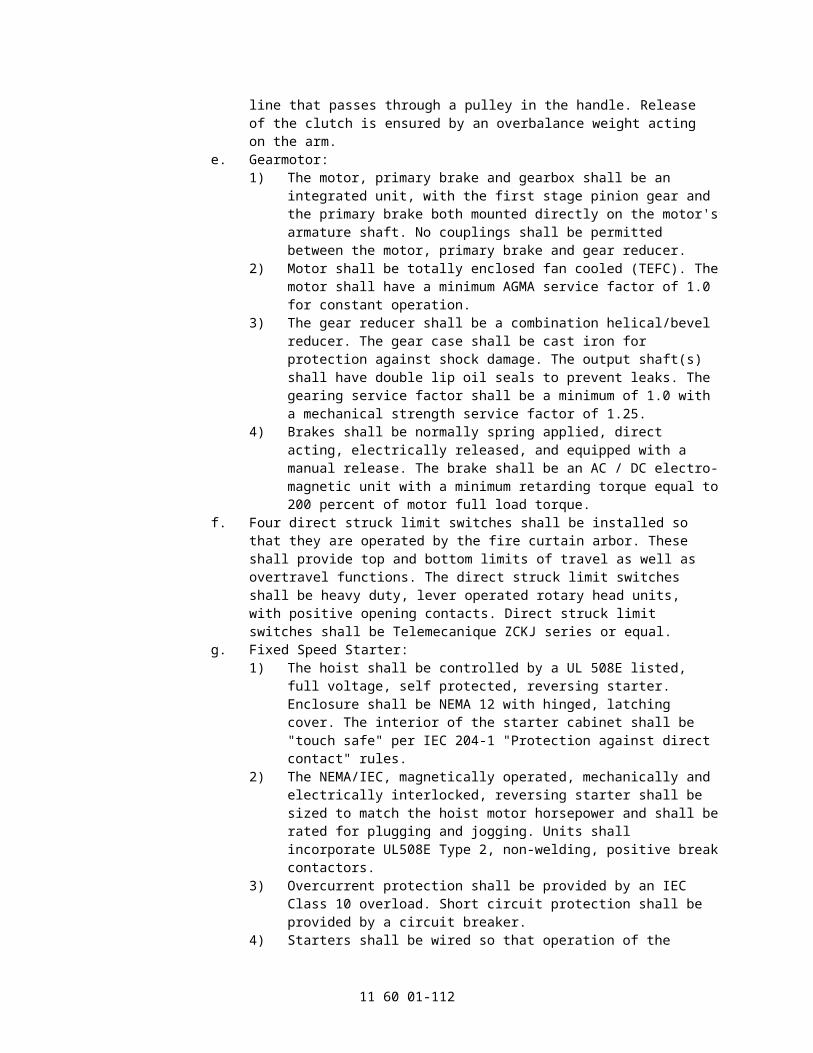
the top spreader plate.11. Lattice Track:
a. The track shall consist of two 2 inch x 2 inch x 1/4 inch (50.8 mm x 50.8 mm x 6.4 mm) angles opposing each other with formed brackets alternating front and back on 2 feet centers. Back brackets shall contain two 9/16 inch (14.3 mm) diameter holes for proper anchorage to the wall.
b. A fabricated steel bracket shall support the bottom of the lattice. Bracket shall have ample clearance for passage of hand line.
12. Fire line System: The manual fire line release system shall consist of a 1/8 inch (3.2 mm) diameter wire rope, with six UL listed fusible links that release at 165 degree F (74 degree C), side mounting pulleys as required, and two fire line release devices, each mounted in a steel enclosure with acrylic viewing window that contains a positive method to release the fire line. Devices shall be mounted 5 feet (1,524 mm) above the stage floor on each side of the proscenium. All other components such as round weight arbors, arbor guards, floor pulleys, etc. required to form a fully functional fire line release system shall be provided.
13. Lift Cables: The curtain lift cables shall be 3/8 inch (9.5 mm) diameter 7 x 19 galvanized utility cable as specified. Cables shall be terminated with corresponding cable thimbles and two forged cable clips or a Swage sleeve fitting at each end. The curtain end of each cable shall be attached to the batten using a 1/2 inch x 6 inch (12.7 mm x 152.4 mm) turnbuckle and pipe clamp.
14. Battens: Battens shall be made of 2 inch (50.8 mm) I.D. nominal, schedule 40 black iron pipe.
15. Safety Chains: Supply one more safety chain than the number of lift cables. 1/4 inch (6.4 mm) minimum, proof coil chains shall be located between lift cables except at the ends where the chains shall be 12 inch (304.8 mm) or less from the end of the batten. Chains shall be attached to the top of the curtain with pipe clamps around the top of the batten and chain shackles. The other end shall be appropriately attached to the building structure.
16. Smoke Pockets with Track: Furnish and install one pair of smoke pockets to extend from the stage floor to a point above the top of the raised curtain or to the height specified in the drawings. Pockets shall consist of a 8 inch (203 mm) deep "Z" channel formed from 1/4 inch (6.4 mm) steel plate and a 1/4 inch x 18 inch (6.4 mm x 457.2 mm) steel plate which shall be bolted to the channels on 2 feet-0 inch (609.6 mm) centers. An angle iron, steel track shall be bolted to the side of the smoke pocket to carry the guides. Channels shall be anchored to the walls on 4 feet-0 inch (1,219 mm) centers.
2.31 FIRE CURTAIN SYSTEMS, CURTAIN ACCESSORIES
A. Dashpot:1. Dash Pot:
a. The hydraulic dash pot shall be sized and valved to fully decelerate a free falling fire safety curtain over the last 10 feet (305 mm) of curtain travel.
b. The top sheave shall be a 12 inch (304.8 mm) diameter cast iron sheave with tapered roller bearings. It shall be connected to a piston rod with 5 feet (1.52 m) of travel.
c. The cylinder shall be fabricated from seamless tubing. Provision shall be made for automatically releasing the oil and returning the unit to an "at rest condition".
d. Provide a fluid reservoir, flow control valve, an oil fill cap and a drain plug.e. Maximum dashpot load is 1250 lbs (567 KG).
2. Dash Pot Line: The 3/8 inch (9.53 mm) diameter dashpot line shall begin at a suitable tieoff point on the structure, travel around the dashpot sheave, through a hole in the arbor stop bracket, over a top sheave/s and end at a round weight arbor with safety chain. A swaged ball on the line shall engage the hole in the arbor and activate the dashpot to decelerate the fire curtain.
11 60 01-112

B. Dashpot - Heavy Duty:1. Dash Pot:
a. The hydraulic dash pot shall be sized and valved to fully decelerate a free falling fire safety curtain within the last 10 feet (3 m) of curtain travel.
b. The top sheave shall be a 12 inch (304.8 mm) diameter, steel sheave with tapered roller bearings and heavy duty side plates. It shall be connected to a piston rod with 5 feet (1.52 m) of travel.
c. The cylinder shall be fabricated from seamless tubing. Provision shall be made for automatically releasing the oil and returning the unit to an "at rest condition".
d. Provide a fluid reservoir, flow control valve, an oil fill cap and a drain plug.e. Maximum dashpot load is 3500 lbs (1,588 KG).
2. Dash Pot Line: The 3/8 inch (9.53 mm) diameter dashpot line shall begin at a suitable tieoff point on the structure, travel around the dashpot sheave, through a hole in the arbor stop bracket, over a top sheave/s and end at a round weight arbor with safety chain. A swaged ball on the line shall engage the hole in the arbor and activate the dashpot to decelerate the fire curtain.
C. Electrical Fire Line Release:1. Product: Sure-Guard II.2. The fire curtain shall be equipped with an electro-mechanical fire line release
mechanism operated by a Sure-Guard II, activated by normally open or normally closed devices including rate of rise heat detectors, smoke detectors, emergency switches, etc. (furnished and installed by others) or by release of tension in the fire line. A switch shall be mounted in the release mechanism enclosure for testing system operation. Activation of the mechanism shall release tension in the fire line which, in turn, allows the fire curtain arbor to rise and the fire curtain to close in the normal manner. The release unit shall incorporate three pulleys permitting its attachment to the fireline at any point and to help prevent accidental release.
3. The release shall contain an integral sealed, rechargeable "Gel Pac" battery and charger to provide emergency power during power interruptions. A charged battery shall keep the curtain raised for a half hour minimum without building power. The release shall operate from a 120 VAC power source provided by others.
4. The electrical fire line release shall be UL Listed.5. The fire line release system shall be the Sure-Guard II.
D. Rate of Rise Heat Detector:1. A heat detector that closes a normally open electrical contact at a fixed temperature or
at a temperature rise of 15 degree F (9.4 degree C) in one minute.2. Rating: 3.0A at 6 to125 VAC, 1.0 A at 6 to 24VAC, 0.3 A 125 VDC, and 0.1 A VDC.3. UL/ULC rating temperature - 135 degree F (57.2 degree C).4. UL/ULC maximum temperature at ceiling - 100 degree F (37.8 degree C).
E. Fire Curtain Systems, Heat Resisting Border:1. Heat resistant border curtains shall be fabricated from ZetexPlus 800 fabric, rated for
1,500 degree F (815.6C) continuous temperature. The fabric shall be woven from highly texturized silica yarn with a proprietary high temperature treatment, and a weight of 25.5 oz. per square yard.
2. Borders shall have a sewn hem on all edges, with webbing, grommets, and ties on 12" (304.8 mm) centers on the top edge.
2.32 COUNTERWEIGHT RIGGING
A. 12 inch Nylon Head Block - Upright.1. Type: Single Purchase 12 inch (304.8 mm) Head Block.2. The sheave shall be filled nylon, with a 12 inch (304.8 mm) outer diameter. The
sheave shall be equipped with a 1 inch (25.4 mm) diameter shaft and two tapered roller bearings.
11 60 01-113

3. Base angles shall be a minimum 2 inch x 1.5 inch x 1/4 inch (50.8 mm x 38.1 mm x 6.4 mm) angle with the short leg turned in and notched to allow clear passage of all cables.
4. Side plates shall be a minimum of 10-gauge (3.57 mm) steel, and shall fully enclose the sheave. Side plates shall be bolted and welded to the base angles for extra strength.
5. Mounting clips shall be steel, 3/8 inch (9.5 mm) thick minimum with a welded toe at least as thick as the mounting steel and punched with two oval holes for 1/2 inch (12.7 mm) bolts, flat washers and lock nuts.
6. The block and associated mounting hardware shall have a recommended working load of at least 3,000 lbs (1,360.8 KG).
7. Head blocks shall be grooved for six or eight 1/4 inch (6.4 mm) lift lines and one 3/4 inch (19.05 mm) hand line.
B. 12 Inch Cast Iron Head Block - Upright.1. Type: Single Purchase 12 inch (304.8 mm) Head Block:2. The sheave shall be an iron casting with a 12 inch (304.8 mm) outer diameter. The
sheave shall be equipped with a 1 inch (25.4 mm) diameter shaft and two tapered roller bearings.
3. Base angles shall be a minimum 2 inch x 1.5 inch x 1/4 inch (50.8 mm x 38.1 mm x 6.34m) angle with the short leg turned in and notched to allow clear passage of all cables.
4. Side plates shall be a minimum of 10-gauge (3.57 mm) steel, and shall fully enclose the sheave. Side plates shall be bolted and welded to the base angles for extra strength.
5. Mounting clips shall be steel, 3/8 inch (9.5 mm) thick minimum with a welded toe at least as thick as the mounting steel and punched with two oval holes for 1/2 inch (12.7 mm) bolts, flat washers and lock nuts.
6. The block and associated mounting hardware shall have a recommended working load of at least 3,000 lbs (1,360 KG).
7. Head blocks shall be grooved for six or eight 1/4 inch (6.4 mm) lift lines and one 3/4 inch (19.1 mm) hand line.
C. 12 Inch Nylon Head Block - Underhung.1. Type: Single Purchase 12 inch (304.8 mm) Head Block:2. The sheave shall be filled nylon with a 12 inch (304.8 mm) outer diameter. The
sheave shall be equipped with a 1 inch (25.4 mm) diameter shaft and two tapered roller bearings.
3. Base angles shall be a minimum 2 inch x 1.5 inch x 1/4 inch (50.8 mm x 38.1 mm x 6.4 mm) angle with the short leg turned in.
4. Side plates shall be a minimum of 10-gauge (3.57 mm) steel, and shall fully enclose the sheave. Side plates shall be bolted and welded to the base angles for extra strength.
5. Auxiliary base angles shall be a minimum 2 inch x 1-1/2 inch x 1/4 inch (50.8 mm x 38.1 mm x 6.4 mm) angle with the short leg turned in. Angles shall be supplied with punched holes and 1/2 inch (12.7 mm) bolts, flat washers and lock nuts.
6. The block and associated mounting hardware shall have a recommended working load of at least 2,500 lbs. (1,134 KG).
7. Head blocks shall be grooved for six or eight 1/4 inch (6.4 mm) lift lines and one 3/4 inch (19.1 mm) hand line.
D. 12 Inch Cast Iron Head Block, Underhung.1. Type: Single Purchase 12 inch (304.8 mm) Head Block:2. The sheave shall be an iron casting with a 12 inch (304.8 mm) outer diameter. The
sheave shall be equipped with a 1 inch (25.4 mm) diameter shaft and two tapered roller bearings.
11 60 01-114

3. Base angles shall be a minimum 2 inch x 1.5 inch x 1/4 inch (50.8 mm x 38.1 mm x 6.4 mm) angle with the short leg turned in.
4. Side plates shall be a minimum of 10-gauge (3.57 mm) steel, and shall fully enclose the sheave. Side plates shall be bolted and welded to the base angles for extra strength.
5. Auxiliary base angles shall be a minimum 2 inch x 1.5 inch x 1/4 inch (50.8 mm x 38.1 mm x 6.4 mm) angle with the short leg turned in. Angles shall be supplied with punched holes and 1/2 inch (12.7 mm) bolts, flat washers and lock nuts.
6. The block and associated mounting hardware shall have a recommended working load of at least 2,500 lbs (1,1334 KG).
7. Head blocks shall be grooved for six or eight 1/4 inch (6.4 mm) lift lines and one 3/4 inch (19.1 mm) hand line.
E. 16 Inch Cast Iron Head Block - Upright.1. Type: Single Purchase 16 inch (406.4 mm) Head block .2. The sheave shall be an iron casting with a 16 inch (406.4 mm) outer diameter. The
sheave shall be equipped with a 1-1/2 inch (38.1 mm) diameter shaft and two tapered roller bearings.
3. Base angles shall be a minimum 2-1/2 inch (63.5 mm) x 2 inch (50.4 mm) x 1/4 inch (6.4 mm) angle with the short leg turned in and notched to allow clear passage of all cables.
4. Side plates shall be a minimum of 7-gauge (4.76 mm) steel, and shall fully enclose the sheave. Side plates shall be bolted and welded to the base angles for extra strength.
5. Mounting clips shall be steel, 3/8 inch (9.5 mm) thick minimum with a welded toe at least as thick as the mounting steel and punched with two oval holes for 1/2 inch (12.7 mm) bolts, flat washers and lock nuts.
6. The block and associated mounting hardware shall have a recommended working load of at least 3,600 lbs. (1,633 KG).
7. Head blocks shall be grooved for eight 3/8 inch (9.5 mm) lift lines and one 1 inch (25.4 mm) hand line.
F. 16 Inch Cast Iron Head Block - Underhung.1. Type: Single Purchase 16 inch (406.4 mm) Head block.2. The sheave shall be an iron casting with a 16 inch (406.4 mm) outer diameter. The
sheave shall be equipped with a 1.5 inch (38.1 mm) diameter shaft and two tapered roller bearings.
3. Base angles shall be a minimum 2.5 inch x 2 inch x 1/4 inch (63.5 mm x 50.8 mm x 6.4 mm) angle with the short leg turned in.
4. Side plates shall be a minimum of 7-gauge (4.76 mm) steel, and shall fully enclose the sheave. Side plates shall be bolted and welded to the base angles for extra strength.
5. Auxiliary base angles shall be a minimum 2.5 inch x 2 inch x 1/4 inch (50.8 mm x 50.8 mm x 6.4 mm) angle with the short leg turned in. Angles shall be supplied with punched holes and 1/2 inch (12.7 mm) bolts, flat washers and lock nuts.
6. The block and associated mounting hardware shall have a recommended working load of at least 3,600 lbs (1,633 KG).
7. Head blocks shall be grooved for eight 3/8 inch (9.52 mm) lift lines and one 1 inch (25.4 mm) hand line.
G. 12 Inch DP, Nylon Head Block - Upright.1. Type: Double Purchase 12 inch (304.8 mm) Head Block:2. The sheave shall be filled nylon, with a 12 inch (304.8 mm) outer diameter. The
sheave shall be equipped with a 1 inch (25.4 mm) diameter shaft and two tapered roller bearings.
3. Base angles shall be a minimum 2 inch x 1.5 inch x 1/4 inch (50.8 mm x 38.1 mm x 6.4 mm) angle with the short leg turned in and notched to allow clear passage of all cables.
11 60 01-115

4. Side plates shall be a minimum of 10-gauge (3.57 mm) steel, and shall fully enclose the sheave. Side plates shall be bolted and welded to the base angles for extra strength.
5. Double purchase blocks shall have punched angles and an additional pipe spacer properly placed to provide tie-off points for lift lines so that proper fleet angles into the arbor top sheave are maintained.
6. Mounting clips shall be steel, 3/8 inch (9.5 mm) thick minimum with a welded toe at least as thick as the mounting steel and punched with two oval holes for 1/2 inch (12.7 mm) bolts, flat washers and lock nuts.
7. The block and associated mounting hardware shall have a recommended working load of at least 3,000 lbs (1,7360.8 kg).
8. Head blocks shall be grooved for six or eight 1/4 inch (6.4 mm) lift lines and one 3/4 inch (19.1 mm) hand line.
H. 12 Inch DP, Cast Head Block - Upright.1. Type: Double Purchase 12 inch (30.48cm) Head Block:2. The sheave shall be an iron casting with a 12 inch (30.48cm) outer diameter. The
sheave shall be equipped with a 1 inch (25.4 mm) diameter shaft and two tapered roller bearings.
3. Base angles shall be a minimum 2 inch x 1-1/2 inch x 1/4 inch (50.8 mm x 38.1 mm x 6.35 mm) angle with the short leg turned in and notched to allow clear passage of all cables.
4. Side plates shall be a minimum of 10-gauge (3.57 mm) steel, and shall fully enclose the sheave. Side plates shall be bolted and welded to the base angles for extra strength.
5. Double purchase blocks shall have punched angles and an additional pipe spacer properly placed to provide tie-off points for lift lines so that proper fleet angles into the arbor top sheave are maintained.
6. Mounting clips shall be steel, 3/8 inch (9.5 mm) thick minimum with a welded toe at least as thick as the mounting steel and punched with two oval holes for 1/2 inch (12.7 mm) bolts, flat washers and lock nuts.
7. The block and associated mounting hardware shall have a recommended working load of at least 3,000lbs (1,360.8 KG).
8. Head blocks shall be grooved for six or eight 1/4 inch (6.4 mm) lift lines and one 3/4 inch (19.05 mm) hand line.
I. 12 Inch DP, Nylon Head Block - Underhung.1. Type: Double Purchase 12 inch (304.8 mm) Head Block:2. The sheave shall be filled nylon with a 12 inch (304.8 mm) outer diameter. The
sheave shall be equipped with a 1 inch diameter shaft and two tapered roller bearings.3. Base angles shall be a minimum 2 inch x 1.5 inch x 1/4 inch (50.8 mm x 38.1 mm x
6.35 mm) angle with the short leg turned in.4. Side plates shall be a minimum of 10-gauge (3.57 mm) steel, and shall fully enclose
the sheave. Side plates shall be bolted and welded to the base angles for extra strength.
5. Double purchase blocks shall have punched angles and an additional pipe spacer properly placed to provide tie-off points for lift lines so that proper fleet angles into the arbor top sheave are maintained.
6. Auxiliary base angles shall be a minimum 2 inch x 1.5 inch x 1/4 inch (50.8 mm x 38.1 mm x 6.4 mm) angle with the short leg turned in. Angles shall be supplied with punched holes and 1/2 inch (12.7 mm) bolts, flat washers and lock nuts.
7. The block and associated mounting hardware shall have a recommended working load of at least 2,500 lbs (1,134 KG).
8. Head blocks shall be grooved for six or eight 1/4 inch (6.35 mm) lift lines and one 3/4 inch (19.05 mm) hand line.
11 60 01-116

J. 12 Inch DP, Cast Iron Head Block - Underhung.1. Type: Double Purchase 12 inch (304.8 mm) Head Block:2. The sheave shall be an iron casting with a 12 inch (304.8 mm) outer diameter. The
sheave shall be equipped with a 1 inch (25.4 mm) diameter shaft and two tapered roller bearings.
3. Base angles shall be a minimum 2 inch x 1.5 inch x 1/4 inch (50.8 mm x 38.1 mm x 6.4 mm) angle with the short leg turned in.
4. Side plates shall be a minimum of 10-gauge (3.57 mm) steel, and shall fully enclose the sheave. Side plates shall be bolted and welded to the base angles for extra strength.
5. Double purchase blocks shall have punched angles and an additional pipe spacer properly placed to provide tie-off points for lift lines so that proper fleet angles into the arbor top sheave are maintained.
6. Auxiliary base angles shall be a minimum 2 inch x 1.5 inch x 1/4 inch (50.8 mm x 38.1 mm x 6.4 mm) angle with the short leg turned in. Angles shall be supplied with punched holes and 1/2 inch (12.7 mm) bolts, flat washers and lock nuts.
7. The block and associated mounting hardware shall have a recommended working load of at least 2,500 lbs (1,134 KG).
8. Head blocks shall be grooved for six or eight 1/4 inch (6.4 mm) lift lines and one 3/4 inch (19.05 mm) hand line.
K. 16 Inch DP, Cast Iron Head Block - Upright.1. Type: Double Purchase 16 inch (406.4 mm) Head block .2. The sheave shall be iron casting with a 16 inch (406.4 mm) outer diameter. The
sheave shall be equipped with a 1.5 inch (38.1 mm) diameter shaft and two tapered roller bearings.
3. Base angles shall be a minimum 2.5 inch x 2 inch x 1/4 inch (63.5 mm x 50.8 mm x 6.4 mm) angle with the short leg turned in and notched to allow clear passage of all cables.
4. Side plates shall be a minimum of 7-gauge (4.76 mm) steel, and shall fully enclose the sheave. Side plates shall be bolted and welded to the base angles for extra strength.
5. Mounting clips shall be steel, 3/8 inch (9.5 mm) thick minimum with a welded toe at least as thick as the mounting steel and punched with two oval holes for 1/2 inch (12.7 mm) bolts, flat washers and lock nuts.
6. The block and associated mounting hardware shall have a recommended working load of at least 3,600 lbs (1,633.9 KG).
7. Head blocks shall be grooved for eight 3/8 inch (9.52 mm) lift lines and one 1 inch (25.4 mm) hand line.
L. 16 Inch DP, Cast Iron Head Block - Underhung.1. Type: Double Purchase 16 inch (406 mm) Head block .2. The sheave shall be iron casting with a 16 inch (406 mm) outer diameter. The sheave
shall be equipped with a 1-1/2 inch (38.1 mm) diameter shaft and two tapered roller bearings.
3. Base angles shall be a minimum 2-1/2 inch x 2 inch x 1/4 inch (57 mm x 50.8 mm x 6.35 mm) angle with the short leg turned in.
4. Side plates shall be a minimum of 7-gauge (4.76 mm) steel, and shall fully enclose the sheave. Side plates shall be bolted and welded to the base angles for extra strength.
5. Double purchase blocks shall have punched angles and an additional pipe spacer properly placed to provide tie-off points for lift lines so that proper fleet angles into the arbor top are maintained.
6. Auxiliary base angles shall be a minimum 2.5 inch x 2 inch x 1/4 inch (50.8 mm x 50.8 mm x 6.4 mm) angle with the short leg turned in. Angles shall be supplied with punched holes and 1/2 inch (12.7 mm) bolts, flat washers and lock nuts.
7. The block and associated mounting hardware shall have a recommended working load of at least 3,600 lbs (1,633 KG).
11 60 01-117

8. Head blocks shall be grooved for eight 3/8 inch (9.53 mm) lift lines and one 1 inch (25.4 mm) hand line.
M. 12 Inch WG, Nylon Head Block - Upright.1. Type: Wire Guide 12 inch (304.8 mm) Head Block:2. The sheave shall be filled nylon, with a 12 inch (304.8 mm) outer diameter. The
sheave shall be equipped with a 1 inch (25.4 mm) diameter shaft and two tapered roller bearings.
3. Base angles shall be a minimum 2 inch x 1.5 inch x 1/4 inch (50.8 mm x 38.1 mm x 6.4 mm) angle with the short leg turned in and notched to allow clear passage of all cables.
4. Side plates shall be a minimum of 10-gauge (3.57 mm) steel, and shall fully enclose the sheave. Side plates shall be bolted and welded to the base angles for extra strength.
5. Blocks used in wire guide systems shall have tie-off points for the guide wires.6. Mounting clips shall be steel, 3/8 inch (9.5 mm) thick minimum with a welded toe at
least as thick as the mounting steel and punched with two oval holes for 1/2 inch (12.7 mm) bolts, flat washers and lock nuts.
7. The block and associated mounting hardware shall have a recommended working load of at least 3,000 lbs (1,360 KG).
8. Head blocks shall be grooved for six or eight 1/4 inch (6.4 mm) lift lines and one 3/4 inch (19.1 mm) hand line.
N. 12 Inch WG, Cast Iron Head Block - Upright.1. Type: Wire Guide 12 inch (304.8 mm) Head Block:2. The sheave shall be iron casting with a 12 inch (304.8 mm) outer diameter. The
sheave shall be equipped with a 1 inch (25.4 mm) diameter shaft and two tapered roller bearings.
3. Base angles shall be a minimum 2 inch x 1.5 inch x 1/4 inch (50.8 mm x 38.1 mm x 6.4 mm) angle with the short leg turned in and notched to allow clear passage of all cables.
4. Side plates shall be a minimum of 10-gauge (3.57 mm) steel, and shall fully enclose the sheave. Side plates shall be bolted and welded to the base angles for extra strength.
5. Blocks used in wire guide systems shall have tie-off points for the guide wires.6. Mounting clips shall be steel, 3/8 inch (9.5 mm) thick minimum with a welded toe at
least as thick as the mounting steel and punched with two oval holes for 1/2 inch (12.7 mm) bolts, flat washers and lock nuts.
7. The block and associated mounting hardware shall have a recommended working load of at least 3,000 lbs (1,360.8 KG).
8. Head blocks shall be grooved for six or eight 1/4 inch (6.4 mm) lift lines and one 3/4 inch (19.1 mm) hand line.
O. 12 Inch WG, Nylon Head Block - Underhung .1. Type: Wire Guide 12 inch (304.8 mm) Head Block:2. The sheave shall be filled nylon with a 12 inch (304.8 mm) outer diameter. The
sheave shall be equipped with a 1 inch (25.4 mm) diameter shaft and two tapered roller bearings.
3. Base angles shall be a minimum 2 inch x 1.5 inch x 1/4 inch (50.8 mm x 38.1 mm x 6.4 mm) angle with the short leg turned in.
4. Side plates shall be a minimum of 10-gauge (3.57 mm) steel, and shall fully enclose the sheave. Side plates shall be bolted and welded to the base angles for extra strength.
5. Blocks used in wire guide systems shall have tie-off points for the guide wires.6. Auxiliary base angles shall be a minimum 2 inch x 1.5 inch x 1/4 inch (50.8 mm x 38.1
mm x 6.4 mm) angle with the short leg turned in. Angles shall be supplied with
11 60 01-118

punched holes and 1/2 inch (12.7 mm) bolts, flat washers and lock nuts.7. The block and associated mounting hardware shall have a recommended working
load of at least 2,500 lbs (1,134 KG).8. Head blocks shall be grooved for six or eight 1/4 inch (6.4 mm) lift lines and one 3/4
inch (19.1 mm) hand line.
P. 12 Inch WG, Cast Iron Head Block - Underhung.1. Type: Wire Guide 12 inch (304.8 mm) Head Block:2. The sheave shall be an iron casting with a 12 inch (304.8 mm) outer diameter. The
sheave shall be equipped with a 1 inch (25.4 mm) diameter shaft and two tapered roller bearings.
3. Base angles shall be a minimum 2 inch x 1.5 inch x 1/4 inch (50.8 mm x 38.1 mm x 6.4 mm) angle with the short leg turned in.
4. Side plates shall be a minimum of 10-gauge (3.57 mm) steel, and shall fully enclose the sheave. Side plates shall be bolted and welded to the base angles for extra strength.
5. Blocks used in wire guide systems shall have tie-off points for the guide wires.6. Auxiliary base angles shall be a minimum 2 inch x 1.5 inch x 1/4 inch (50.8 mm x 38.1
mm x 6.4 mm) angle with the short leg turned in. Angles shall be supplied with punched holes and 1/2 inch (12.7 mm) bolts, flat washers and lock nuts.
7. The block and associated mounting hardware shall have a recommended working load of at least 2,500 lbs (1,134 KG).
8. Head blocks shall be grooved for six or eight 1/4 inch (6.4 mm) lift lines and one 3/4 inch (19.1 mm) hand line.
Q. Staggered Sheave Nylon Head Block.1. Type: Staggered Sheave Head Block:2. The block sheaves shall have 8.5 inch (215.9 mm) outside diameters, and shall be
filled nylon. Each sheave shall be equipped with a 17 mm (.67in) diameter shaft and two sealed, precision ball bearings. Sheaves shall be spaced in the housing so cables align with the hoist drum grooving to eliminate fleet angles.
3. Base angles shall be a minimum 2 inch x 1.5 inch x 1/4 inch (50.8 mm x 38.1 mm x 6.4 mm) angle punched with a mounting hole pattern for clip attachment.
4. Side plates shall be a minimum of 12-gauge (2.78 mm) steel, and shall fully enclose the sheaves. Side plates shall be bolted and welded to the base angles for strength.
5. Auxiliary base angles shall be a minimum 2 inch x 1.5 inch x 1/4 inch (50.8 mm x 38.1 mm x 6.4 mm) angle with the short leg turned in. Angles shall be supplied with punched holes and 1/2 inch (12.7 mm) bolts, flat washers and lock nuts.
6. The block and associated mounting hardware shall have a minimum recommended working load at least equal to the hoist capacity and associated stresses.
7. Head blocks shall have ___ sheaves grooved for one 1/4 inch (6.4 mm) lift line each.
R. Staggered Sheave Cast Iron Head Block.1. Type: Staggered Sheave Head Block:2. The block sheaves shall be iron castings with 8.5 inch (215.9 mm) outside diameters.
Each sheave shall be equipped with a 17 mm (.67in) diameter shaft and two sealed, precision ball bearings. Sheaves shall be spaced in the housing so cables align with the hoist drum grooving to eliminate fleet angles.
3. Base angles shall be a minimum 2 inch x 1.5 inch x 1/4 inch (50.8 mm x 38.1 mm x 6.4 mm) angle punched with a mounting hole pattern for clip attachment.
4. Side plates shall be a minimum of 12-gauge (2.78 mm) steel, and shall fully enclose the sheaves. Side plates shall be bolted and welded to the base angles for strength.
5. Auxiliary base angles shall be a minimum 2 inch x 1.5 inch x 1/4 inch (50.8 mm x 38.1 mm x 6.4 mm) angle with the short leg turned in. Angles shall be supplied with punched holes and 1/2 inch (12.7 mm) bolts, flat washers and lock nuts.
6. The block and associated mounting hardware shall have a minimum recommended
11 60 01-119

working load at least equal to the hoist capacity and associated stresses.7. Head blocks shall have sheaves grooved for one 1/4 inch (6.4 mm) lift line each,.
a. Number of Sheave Grooves: ______.
S. 8 Inch Nylon Universal Loft Block.1. The sheave shall have an 8-1/2 inch (215.9 mm) outside diameter, and shall be filled
nylon. The sheave shall be equipped with a 17 mm (.67in) diameter shaft and two sealed, precision ball bearings.
2. Base angles shall be a minimum 1-1/2 inch x 1-1/2 inch x 3/16 inch (38.1 mm x 38.1 mm x 4.76 mm) angle punched with a universal hole pattern for easy installation.
3. Side plates shall be a minimum of 12-gauge (2.78 mm) steel, and shall fully enclose the sheave. Side plates shall be bolted to the base angles.
4. The block and associated mounting hardware shall have a recommended working load of at least 750 lbs. (340.2 KG), and shall be designed for use in either upright or underhung usage.
5. Loft blocks shall be grooved for one 1/4 inch (6.4 mm) lift line.
T. 8 Inch Nylon Universal Loft Block.1. The sheave shall have an 8-1/2 inch (215.9 mm) outside diameter, and shall be filled
nylon. The sheave shall be equipped with a 17 mm (.67 inch) diameter shaft and two tapered roller bearings.
2. Base angles shall be a minimum 1.5 inch x 1.5 inch x 3/16 inch (38.1 mm x 38.1 mm x 4.76 mm) angle punched with a universal hole pattern for easy installation.
3. Side plates shall be a minimum of 12-gauge (2.78 mm) steel, and shall fully enclose the sheave. Side plates shall be bolted to the base angles.
4. The block and associated mounting hardware shall have a recommended working load of at least 750 lbs. (340.2 KG), and shall be designed for use in either upright or underhung usage.
5. Loft blocks shall be grooved for one 1/4 inch (6.4 mm) lift line.
U. 8 Inch Cast Iron Universal Loft Block.1. The sheave shall have an 8-1/2 inch (215.9 mm) outside diameter, and shall be an
iron casting, with a machined groove. The sheave shall be equipped with a 17 mm (0.67in.) diameter shaft and two sealed, precision ball bearings.
2. Base angles shall be a minimum 1-1/2 inch x 1-1/2 inch x 3/16 inch (38.1 mm x 38.1 mm x 4.76 mm) angle punched with a universal hole pattern for easy installation.
3. Side plates shall be a minimum of 12-gauge (2.78 mm) steel, and shall fully enclose the sheave. Side plates shall be bolted to the base angles.
4. The block and associated mounting hardware shall have a recommended working load of at least 500 lbs. (227 KG) and shall be designed for use in either upright or underhung usage.
5. Loft blocks shall be grooved for one 1/4 inch (6.4 mm) lift line.
V. 8 Inch Cast Iron Universal Loft Block.1. The sheave shall have an 8-1/2 inch (215.9 mm) outside diameter, and shall be an
iron casting, with a machined groove. The sheave shall be equipped with a 17 mm (0.67in.) diameter shaft and two tapered roller bearings.
2. Base angles shall be a minimum 1-1/2 inch x 1-1/2 inch x 3/16 inch (38.1 mm x 38.1 mm x 4.76 mm) angle punched with a universal hole pattern for easy installation.
3. Side plates shall be a minimum of 12-gauge (2.78 mm) steel, and shall fully enclose the sheave. Side plates shall be bolted to the base angles.
4. The block and associated mounting hardware shall have a recommended working load of at least 500 lbs. (227 KG) and shall be designed for use in either upright or underhung usage.
5. Loft blocks shall be grooved for one 1/4 inch (6.4 mm) lift line.
W. 8 Inch Nylon Universal Loft Block - 2 Line.
11 60 01-120

1. Loft Block - 2 Line:2. The sheave shall have an 8-1/2 inch (215.9 mm) outside diameter, and shall be filled
nylon. The sheave shall be equipped with a 17 mm (.67in) diameter shaft and two sealed, precision ball bearings.
3. Base angles shall be a minimum 1-1/2 inch x 1-1/2 inch x 3/16 inch (38.1 mm x 38.1 mm x 4.76 mm) angle punched with a universal hole pattern for easy installation.
4. Side plates shall be a minimum of 12-gauge (2.78 mm) steel, and shall fully enclose the sheave. Side plates shall be bolted to the base angles.
5. The block and associated mounting hardware shall have a recommended working load of at least 750 lbs. (340.2 KG), and shall be designed for use in either upright or underhung usage.
6. Loft blocks shall be grooved for two 1/4 inch (6.4 mm) lift lines.
X. 8 Inch Nylon Universal Loft Block - 2 Line.1. Loft Block - 2 Line:2. The sheave shall have an 8-1/2 inch (215.9 mm) outside diameter, and shall be filled
nylon. The sheave shall be equipped with a 17 mm (.67in) diameter shaft and two tapered roller bearings.
3. Base angles shall be a minimum 1.5 inch x 1.5 inch x 3/16 inch (38.1 mm x 38.1 mm x 4.76 mm) angle punched with a universal hole pattern for easy installation.
4. Side plates shall be a minimum of 12-gauge (2.78 mm) steel, and shall fully enclose the sheave. Side plates shall be bolted to the base angles.
5. The block and associated mounting hardware shall have a recommended working load of at least 750 lbs. (340.2 KG), and shall be designed for use in either upright or underhung usage.
6. Loft blocks shall be grooved for two 1/4 inch (6.4 mm) lift lines.
Y. 8 Inch Cast Iron Universal Loft Block - 2 Line.1. Loft Block - 2 Line:2. The sheave shall have an 8-1/2 inch (215.9 mm) outside diameter, and shall be an
iron casting, with two machined grooves. The sheave shall be equipped with a 17 mm diameter shaft and two sealed, precision ball bearings.
3. Base angles shall be a minimum 1-1/2 inch x 1-1/2 inch x 3/16 inch (38.1 mm x 38.1 mm x 4.76 mm) angle punched with a universal hole pattern for easy installation.
4. Side plates shall be a minimum of 12-gauge (2.78 mm) steel, and shall fully enclose the sheave. Side plates shall be bolted and welded to the base angles.
5. The block and associated mounting hardware shall have a recommended working load of at least 500 lbs. (226.8 KG) per line and 750 lbs. (340.2 KG) total, and shall be designed for use in either upright or underhung usage.
6. Loft blocks shall be grooved for two 1/4 inch (6.4 mm) lift lines.
Z. 8 Inch Cast Iron Universal Loft Block - 2 Line.1. Loft Block - 2 Line:2. The sheave shall have an 8-1/2 inch (215.9 mm) outside diameter, and shall be an
iron casting, with two machined grooves. The sheave shall be equipped with a 17 mm diameter shaft and two tapered roller bearings.
3. Base angles shall be a minimum 1.5 inch x 1.5 inch x 3/16 inch (38.1 mm x 38.1 mm x 4.76 mm) angle punched with a universal hole pattern for easy installation.
4. Side plates shall be a minimum of 12-gauge (2.78 mm) steel, and shall fully enclose the sheave. Side plates shall be bolted and welded to the base angles.
5. The block and associated mounting hardware shall have a recommended working load of at least 500 lbs. (226.8 KG) per line and 750 lbs. (340.2 KG) total, and shall be designed for use in either upright or underhung usage.
6. Loft blocks shall be grooved for two 1/4 inch (6.4 mm) lift lines.
AA. 8 Inch Nylon Loft Block, Upright, 4 & 8 Line.
11 60 01-121

1. Loft Block - 4 & 8 Line:2. The sheave shall have an 8.5 inch (215.9 mm) outside diameter, and shall be filled
nylon. The sheave shall be equipped with a 1 inch (25.4 mm) diameter shaft and two tapered roller bearings.
3. Base angles shall be a minimum 1.5 inch x 1.5 inch x 3/16 inch (38.1 mm x 38.1 mm x 4.76 mm) angle.
4. Side plates shall be a minimum of 10-gauge (3.57 mm) steel, and shall fully enclose the sheave. Side plates shall be bolted and welded to the base angles.
5. The block and associated mounting hardware shall have a recommended working load of at least 750 lbs. (340.2 KG) per line and 1300 lbs. (589.7 KG) total, and shall be designed for use in either upright or underhung usage.
6. Loft blocks shall be grooved for 4 or 8 - 1/4 inch (6.4 mm) lift lines.
BB. 8 Inch Cast Iron Loft Block, Underhung, 4 & 8 Line.1. Loft Block - 4 & 8 Line:2. The sheave shall have an 8.5 inch (215.9 mm) outside diameter, and shall be an iron
casting, with machined grooves. The sheave shall be equipped with a 1 inch (25.4 mm) diameter shaft and two tapered roller bearings.
3. Base angles shall be a minimum 1.5 inch x 1.5 inch x 3/16 inch (38.1 mm x 38.1 mm x 4.76 mm) angle.
4. Side plates shall be a minimum of 10-gauge (3.57 mm) steel, and shall fully enclose the sheave. Side plates shall be bolted to the base angles.
5. The block and associated mounting hardware shall have a recommended working load of at least 500 lbs. (226.8 KG) per line and 1300 lbs. (589.7 KG) total, and shall be designed for use in either upright or underhung usage.
6. Loft blocks shall be grooved for 4 or 8 - 1/4 inch (6.4 mm) lift lines.
CC. 12 Inch Cast Iron Universal Loft Block.1. The sheave shall have a 12 inch (304.8 mm) pitch diameter, and shall be an iron
casting, with a machined groove. The sheave shall be equipped with a 1 inch (25.4 mm) diameter shaft and two tapered roller bearings.
2. Base angles shall be a minimum 1.5 inch x 2 inch x 3/16 inch (38.1 mm x 50.8 mm x 4.76 mm) angle.
3. Side plates shall be a minimum of 10-gauge steel (3.57 mm), and shall fully enclose the sheave. Side plates shall be bolted to the base angles.
4. Loft blocks shall be grooved for one 1/4 inch or 3/8 inch (6.4 mm or 9.52 mm) lift line.5. The block and associated mounting hardware shall have a recommended working
load of at least 700 lbs. (317.5 KG) for 1/4 inch (6.4 mm) cable or 1050 lbs. (476.3 KG) for 3/8 inch (9.52 mm) cable, and shall be designed for use in either upright or underhung usage.
DD. 16 Inch Steel, Universal Loft Block.1. The steel sheave shall have a 16 inch (406.4 mm) diameter with a machined groove.
The sheave shall be equipped with a 1 inch (25.4 mm) diameter shaft and two tapered roller bearings.
2. Base angles shall be a minimum 2 inch x 2 inch x 1/4 inch (50.8 mm x 50.8 mm x 6.4 mm) angle.
3. Side plates shall be a minimum of 7-gauge (4.76 mm) steel, and shall fully enclose the sheave. Side plates shall be bolted to the base angles.
4. The block and associated mounting hardware shall have a recommended working load of at least 1400 lbs (635 KG), and shall be designed for use in either upright or underhung usage.
5. Loft blocks shall be grooved for one 3/8 inch (9.52 mm) lift line.
EE. 8 Inch Nylon Loft Block, Underhung (19 Series).1. Underhung Loft Block:
11 60 01-122
2. The sheave shall have an 8-1/2 inch (215.9 mm) outside diameter and shall be filled nylon. The sheave shall be equipped with a 17 mm (.67in) diameter shaft and two sealed, precision ball bearings.
3. Side plates shall be a minimum of 10-gauge (3.57 mm) steel, with a cut-out to grasp the beam flange.
4. A machined steel 3/4 inch (19.1 mm) drawbolt and steel clip shall grasp the opposing beam flange and allow a 5 inch (127 mm) grip adjustment to accommodate a range of beam sizes.
5. The block shall have a recommended working load of at least 500 lbs. (226.8 mm).6. Loft blocks shall be grooved for one 1/4 inch (6.4 mm) lift line.
FF. 8 Inch Nylon Loft Block, Underhung (19 Series).1. Underhung Loft Block:2. The sheave shall have an 8-1/2 inch (215.9 mm) outside diameter and shall be filled
nylon. The sheave shall be equipped with a 17 mm (.67in) diameter shaft and two tapered roller bearings.
3. Side plates shall be a minimum of 10-gauge (3.57 mm) steel, with a cut-out to grasp the beam flange.
4. A machined steel 3/4 inch (19.1 mm) drawbolt and steel clip shall grasp the opposing beam flange and allow a 5 inch (127 mm) grip adjustment to accommodate a range of beam sizes.
5. The block shall have a recommended working load of at least 500 lbs. (226.8 mm).6. Loft blocks shall be grooved for one 1/4 inch (6.4 mm) lift line.
GG. 8 Inch Cast Iron Loft Block, Underhung (19 Series).1. Underhung Loft Block:2. The sheave shall have an 8-1/2 inch (215.9 mm) outside diameter and shall be an iron
casting with a machined groove. The sheave shall be equipped with a 17 mm (.67in) diameter shaft and two sealed, precision ball bearings.
3. Side plates shall be a minimum of 10-gauge (3.57 mm) steel, with a cut-out to grasp the beam flange.
4. A machined steel 3/4 inch (19.1 mm) drawbolt and steel clip shall grasp the opposing beam flange and allow a 5 inch (127 mm) grip adjustment to accommodate a range of beam sizes.
5. The block shall have a recommended working load of at least 500 lbs. (226.8 mm).6. Loft blocks shall be grooved for one 1/4 inch (6.4 mm) lift line.
HH. 8 Inch Cast Iron Loft Block, Underhung (19 Series).1. Underhung Loft Block:2. The sheave shall have an 8-1/2 inch (215.9 mm) outside diameter and shall be an iron
casting with a machined groove. The sheave shall be equipped with a 17 mm (.67in) diameter shaft and two tapered roller bearings.
3. Side plates shall be a minimum of 10-gauge (3.57 mm) steel, with a cut-out to grasp the beam flange.
4. A machined steel 3/4 inch (19.1 mm) drawbolt and steel clip shall grasp the opposing beam flange and allow a 5 inch (127 mm) grip adjustment to accommodate a range of beam sizes.
5. The block shall have a recommended working load of at least 500 lbs. (226.8 mm).6. Loft blocks shall be grooved for one 1/4 inch (6.4 mm) lift line.
II. 8 Inch Nylon Loft Block, Underhung (19 Series) - 2 Line.1. Underhung Loft Block - 2 Line:2. The sheave shall have an 8-1/2 inch (215.9 mm) outside diameter, and shall be filled
nylon. The sheave shall be equipped with a 17 mm (.67in) diameter shaft and two sealed, precision ball bearings.
3. Side plates shall be a minimum of 10-gauge (3.57 mm) steel, with a cutout to grasp
11 60 01-123

the beam flange.4. A machined steel 3/4 inch (19.1 mm) drawbolt and steel clip shall grasp the opposing
beam flange and allow a 5 inch (127 mm) grip adjustment to accommodate a range of beam sizes.
5. The block shall have a recommended working load of at least 500 lbs. (226.8 mm).6. Loft blocks shall be grooved for two 1/4 inch (6.4 mm) lift lines.
JJ. 8 Inch Nylon Loft Block, Underhung (19 Series) - 2 Line.1. Underhung Loft Block - 2 Line:2. The sheave shall have an 8.5 inch (215.9 mm) outside diameter, and shall be filled
nylon. The sheave shall be equipped with a 17 mm (.67in) diameter shaft and two tapered roller bearings.
3. Side plates shall be a minimum of 10-gauge (3.57 mm) steel, with a cutout to grasp the beam flange.
4. A machined steel 3/4 inch (19.1 mm) drawbolt and steel clip shall grasp the opposing beam flange and allow a 5 inch (127 mm) grip adjustment to accommodate a range of beam sizes.
5. The block shall have a recommended working load of at least 500 lbs. (226.8 mm).6. Loft blocks shall be grooved for two 1/4 inch (6.4 mm) lift lines.
KK. 8 Inch Cast Iron Loft Block, Underhung (19 Series) - 2 Line.1. Underhung Loft Block - 2 Line:2. The sheave shall have an 8-1/2 inch (215.9 mm) outside diameter, and shall be an
iron casting, with two machined grooves. The sheave shall be equipped with a 17 mm (.67 inch) diameter shaft and two sealed, precision ball bearings.
3. Side plates shall be a minimum of 10-gauge steel (3.57 mm), with a cutout to grasp the beam flange.
4. A machined steel 3/4 inch (19.1 mm) drawbolt and steel clip shall grasp the opposing beam flange and allow a 5 inch (127 mm) grip adjustment to accommodate a range of beam sizes.
5. The side plates shall be rigidly fastened together with a minimum of three 1/4 inch (6.4 mm) bolts and pipe, two of which prevent cables from escaping the sheave grooves.
6. The block shall have a recommended working load of at least 500 lbs. (226.8 mm).7. Loft blocks shall be grooved for two 1/4 inch (6.4 mm) lift lines.
LL. 8 Inch Cast Iron Loft Block, Underhung (19 Series) - 2 Line.1. Underhung Loft Block - 2 Line:2. The sheave shall have an 8-1/2 inch (215.9 mm) outside diameter, and shall be an
iron casting, with two machined grooves. The sheave shall be equipped with a 17 mm (.67in) diameter shaft and two tapered roller bearings.
3. Side plates shall be a minimum of 10-gauge steel (3.57 mm), with a cutout to grasp the beam flange.
4. A machined steel 3/4 inch (19.1 mm) drawbolt and steel clip shall grasp the opposing beam flange and allow a 5 inch (127 mm) grip adjustment to accommodate a range of beam sizes.
5. The side plates shall be rigidly fastened together with a minimum of three 1/4 inch (6.4 mm) bolts and pipe, two of which prevent cables from escaping the sheave grooves.
6. The block shall have a recommended working load of at least 500 lbs. (226.8 mm).7. Loft blocks shall be grooved for two 1/4 inch (6.4 mm) lift lines.
MM. 8 Inch Nylon Loft Block, Underhung (19 Series) - 4 & 8 Line.1. Underhung Loft Block - 4 & 8 Line:2. The sheave shall have an 8-1/2 inch (215.9 mm) outside diameter and shall be filled
nylon. The sheave shall be equipped with a 1 inch (25.4 mm) diameter shaft and two tapered roller bearings.
3. Side plates shall be a minimum of 10-gauge (3.57 mm) steel, with a cut-out to grasp
11 60 01-124

the beam flange.4. A machined steel 3/4 inch (19.1 mm) drawbolt and steel clip shall grasp the opposing
beam flange and allow a 4 inch (101.6 mm) grip adjustment to accommodate a range of beam sizes.
5. The side plates shall be rigidly fastened together with a minimum of three 1/4 inch (6.4 mm) bolts and pipe, two of which prevent cables from escaping the sheave grooves.
6. The block shall have a recommended working load of at least 700 lbs. (317.5 KG).7. Loft blocks shall be grooved for 4 or 8 - 1/4 inch (6.4 mm) lift lines.
NN. 8 inch Cast Iron Loft Block, Underhung (19 Series) - 4 & 8 Line.1. Underhung Loft Block - 4 & 8 Line:2. The sheave shall have an 8.5 inch (215.9 mm) outside diameter, and shall be an iron
casting, with machined grooves. The sheave shall be equipped with a 1 inch (25.4 mm) diameter shaft and two tapered roller bearings.
3. Side plates shall be a minimum of 10-gauge (3.57 mm) steel, with a cut-out to grasp the beam flange.
4. A machined steel 3/4 inch (19.05 mm) drawbolt and steel clip shall grasp the opposing beam flange and allow a 4 inch (101.6 mm) grip adjustment to accommodate a range of beam sizes.
5. The side plates shall be rigidly fastened together with a minimum of three 1/4 inch (6.4 mm) bolts and pipe, two of which prevent cables from escaping the sheave grooves.
6. The block shall have a recommended working load of at least 700 lbs (317.5 KG).7. Loft blocks shall be grooved for 4 or 8 - 1/4 inch (6.4 mm) lift lines.
OO. 12 Inch Cast Iron Loft Block, Underhung (19 Series).1. Underhung Loft Block:2. The sheave shall have a 12 inch (304.8 mm) outside diameter, and shall be an iron
casting, with a machined groove. The sheave shall be equipped with a 1 inch (25.4 mm) diameter shaft and two tapered roller bearings.
3. Side plates shall be a minimum of 7-gauge (4.76 mm) steel, with a cut-out to grasp the beam flange.
4. A machined steel 3/4 inch (19.1 mm) drawbolt and steel clip shall grasp the opposing beam flange and allow a 5 inch (127 mm) grip adjustment to accommodate a range of beam sizes.
5. The block shall have a recommended working load of at least 675 lbs (306.2 KG).6. Loft blocks shall be grooved for one 1/4 inch or 3/8 inch (6.4 mm or 9.52 mm) lift line.
PP. 8 Inch Nylon Loft Block.1. Underhung Loft Block:2. The sheave shall have an 8-1/2 inch (215.9 mm) outside diameter and shall be filled
nylon. The sheave shall be equipped with a 17 mm (.67in) diameter shaft and two sealed, precision ball bearings.
3. Side plates shall be a minimum of 10-gauge steel (3.57 mm), with a cut-out to grasp the beam flange.
4. A machined steel 3/4 inch (19.1 mm) drawbolt and steel clip shall grasp the opposing beam flange and allow a 5 inch (127 mm) grip adjustment to accommodate a range of beam sizes.
5. The block shall have a recommended working load of at least 500 lbs. (226.8 KG).6. Loft blocks shall be grooved for one 3/16 inch (4.76 mm) lift line.
QQ. 8 Inch Nylon Loft Block.1. Underhung Loft Block:2. The sheave shall have an 8-1/2 inch (215.9 mm) outside diameter and shall be filled
nylon. The sheave shall be equipped with a 17 mm (.67in) diameter shaft and two tapered roller bearings.
3. Side plates shall be a minimum of 10-gauge steel (3.57 mm), with a cut-out to grasp
11 60 01-125

the beam flange.4. A machined steel 3/4 inch (19.1 mm) drawbolt and steel clip shall grasp the opposing
beam flange and allow a 5 inch (127 mm) grip adjustment to accommodate a range of beam sizes.
5. The block shall have a recommended working load of at least 500 lbs. (226.8 KG).6. Loft blocks shall be grooved for one 3/16 inch (4.76 mm) lift line.
RR. 8 Inch Nylon Univ. Loft Block.1. The sheave shall have an 8-1/2 inch (215.9 mm) outside diameter, and shall be filled
nylon. The sheave shall be equipped with a 17 mm (.67in) diameter shaft and two sealed, precision ball bearings.
2. Base angles shall be a minimum 1-1/2 inch x 1-1/2 inch x 3/16 inch (38.1 mm x 38.1 mm x 4.76 mm) angle punched with a universal hole pattern for easy installation.
3. Side plates shall be a minimum of 12-gauge steel (2.78 mm), and shall fully enclose the sheave. Side plates shall be bolted to the base angles.
4. The block and associated mounting hardware shall have a recommended working load of at least 500 lbs. (226.8 KG), and shall be designed for use in either upright or underhung usage.
5. Loft blocks shall be grooved for one 3/16 inch (4.76 mm) lift line.
SS. 8 Inch Nylon Universal Loft Block.1. The sheave shall have an 8-1/2 inch (215.9 mm) outside diameter, and shall be filled
nylon. The sheave shall be equipped with a 17 mm (.67in) diameter shaft and two tapered roller bearings.
2. Base angles shall be a minimum 1-1/2 inch x 1-1/2 inch x 3/16 inch (38.1 mm x 38.1 mm x 4.76 mm) angle punched with a universal hole pattern for easy installation.
3. Side plates shall be a minimum of 12-gauge steel (2.78 mm), and shall fully enclose the sheave. Side plates shall be bolted to the base angles.
4. The block and associated mounting hardware shall have a recommended working load of at least 500 lbs. (226.8 KG), and shall be designed for use in either upright or underhung usage.
5. Loft blocks shall be grooved for one 3/16 inch (4.76 mm) lift line.
TT. 8 inch Nylon Loft Block, Underhung - 8LN.1. Underhung Loft Block - 8 Line:2. The sheave shall have an 8.5 inch (215.9 mm) outside diameter and shall be filled
nylon. The sheave shall be equipped with a 1 inch (25.4 mm) diameter shaft and two tapered roller bearings.
3. Side plates shall be a minimum of 10-gauge (3.57 mm) steel, with a cut-out to grasp the beam flange.
4. A machined steel 3/4 inch (19.05 mm) drawbolt and steel clip shall grasp the opposing beam flange and allow a 4 inch (101.6 mm) grip adjustment to accommodate a range of beam sizes.
5. The side plates shall be rigidly fastened together with a minimum of three 1/4 inch (6.45 mm) bolts and pipe, two of which prevent cables from escaping the sheave grooves.
6. The block shall have a recommended working load of at least 700 lbs (317.5 KG).7. Loft blocks shall be grooved for eight, 3/16 inch (4.76 mm) lift lines.
UU. 8 Inch Nylon Loft Block, Upright, 8LN.1. Loft Block - 8 Line:2. The sheave shall have an 8.5 inch (215.9 mm) outside diameter, and shall be filled
nylon. The sheave shall be equipped with a 1 inch (25.4 mm) diameter shaft and two tapered roller bearings.
3. Base angles shall be a minimum 1.5 inch x 1.5 inch x 3/16 inch (38.1 mm x 38.1 mm x 4.763 mm) angle.
11 60 01-126

4. Side plates shall be a minimum of 10-gauge steel (3.57 mm), and shall fully enclose the sheave. Side plates shall be bolted and welded to the base angles.
5. The block and associated mounting hardware shall have a recommended working load of at least 500 lbs. (226.8 KG) per line and 1300 lbs. (598.7 KG) total load, and shall be designed for use in either upright or underhung usage.
6. Loft blocks shall be grooved for eight, 3/16 inch (4.763 mm) lift lines.
VV. Idler Assemblies.1. Loft block idlers shall be provided to carry the weight of the cables and prevent
rubbing against adjacent block side plates. They shall not be installed to carry line loads or to act as deflector or mule blocks.
2. Idler assemblies shall consist of one or two 3-1/2 inch (88.9 mm) diameter, 3-line filled ABS idler pulleys mounted on the side of the loft block housing.
3. The sheaves shall have 1/4 inch (6.4 mm) cable grooves and two sealed, precision ball bearings and shall ride on a 1/4 inch (6.4 mm) shaft inserted through the block housing.
4. A 1/8 inch (3.2 mm) diameter bail shall mount in the housing and captivate the cables in the grooves.
5. All nuts shall be of the nylon insert self-locking type.
WW. Pivot Bracket.1. Pivot brackets mount loft blocks to beams with more than 1-1/2 degrees of slope.2. They consist of a pair of angles that bolt to the block base angles and a matching pair
of angles that mount to the beam with clips. A 3/4 inch (19.1 mm) diameter threaded rod connects the two sets of angle to provide a hinge point.
XX. 8 Inch Cast Iron Mule Block - 1 & 2 Line.1. 8 inch (203 mm) Mule Blocks - 1 & 2 Line.2. The sheave shall have an 8-1/2 inch (215.9 mm) outside diameter and shall be an iron
casting with a machined groove.3. The sheave shall be equipped with a 17 mm (0.67 inch) diameter shaft and two,
sealed, precision ball bearings.4. Side plates shall be a minimum of 7-gauge (4.76 mm) steel, and shall fully enclose the
sheave.5. Side plates shall be fillet welded to an 8 inch (203.2 mm) structural steel channel or a
3 gage (6.2 mm) formed channel base. Brace tubes with a minimum size of 2 inch x 2 inch x 3/16 inch (50.8 mm x 50.8 mm x 4.8 mm) shall be welded to both side plates and the channel base for added strength.
6. There shall be a minimum of four 3/8 inch (9.52 mm) bolts with spacers between the side plates for structural strength and to prevent cables from escaping the sheave grooves.
7. The block shall have a recommended working load maximum of 500 lbs. (226.8 KG) per line.
8. Mule blocks shall be grooved for one or two 1/4 inch (6.4 mm) lines.
YY. 8 Inch Cast Iron Mule Block - 1 & 2 Line.1. 8 inch (203 mm) Mule Blocks - 1 & 2 Line.2. The sheave shall have an 8.5 inch (215.9 mm) outside diameter and shall be an iron
casting with a machined groove.3. The sheave shall be equipped with a 17 mm (0.67 inch) diameter shaft and two
tapered roller bearings.4. Side plates shall be a minimum of 7-gauge (4.76 mm) steel, and shall fully enclose the
sheave.5. Side plates shall be fillet welded to an 8 inch (203.2 mm) structural steel channel or a
3 gage (6.2 mm) formed channel base. Brace tubes with a minimum size of 2 inch x 2 inch x 3/16 inch (50.8 mm x 50.8 mm x 4.8 mm) shall be welded to both side plates
11 60 01-127

and the channel base for added strength.6. There shall be a minimum of four 3/8 inch (9.52 mm) bolts with spacers between the
side plates for structural strength and to prevent cables from escaping the sheave grooves.
7. The block shall have a recommended working load maximum of 500 lbs. (226.8 KG) per line.
8. Mule blocks shall be grooved for one or two 1/4 inch (6.4 mm) lines.
ZZ. 8 Inch Cast Iron Mule Block - 4 & 8 Line.1. 8 inch (203 mm) Mule Blocks - 4 & 8 Line.2. The sheave shall have an 8-1/2 inch (215 mm) outside diameter and shall be an iron
casting with machined grooves.3. The sheave shall be equipped with a 1 inch (25.4 mm) diameter shaft and two tapered
roller bearings.4. Side plates shall be a minimum of 7-gauge (4.76 mm) steel, and shall fully enclose the
sheave.5. Side plates shall be fillet welded to an 8 inch (203.2 mm) structural steel channel or a
3 gauge (6.2 mm) formed channel base. Brace tubes with a minimum size of 2 inch x 2 inch x 1/4 inch (50.8 mm x 50.8 mm x 6.35 mm) shall be welded to both side plates and the channel base for added strength.
6. There shall be a minimum of four 3/8 inch (9.52 mm) bolts with spacers between the side plates for structural strength and to prevent cables from escaping the sheave grooves.
7. The block shall have a recommended working load of at least 500 lbs. (226.8 KG) per line with a total load not to exceed 2000 lbs. (907.2 KG) using a 90 degree wrap or 1400 lbs. (635.0 kg) using a 180 degree wrap.
8. Mule blocks shall be grooved for four or eight 1/4 inch (6.4 mm) lines.
AAA. 12 Inch Cast Iron Mule Block.1. 12 inch (304.8 mm) Mule Blocks:2. The sheave shall have a 12 inch (304.8 mm) outside diameter and shall be an iron
casting with a machined groove.3. The sheave shall be equipped with a 1 inch (25.4 mm) diameter shaft and two tapered
roller bearings.4. Side plates shall be a minimum of 7-gauge (4.76 mm) steel, and shall fully enclose the
sheave.5. Side plates shall be fillet welded to an 8 inch (203 mm) structural steel channel or a 3
gauge (6.2 mm) formed channel base. Brace tubes with a minimum size of 2 inch x 2 inch x 1/4 inch (50.8 mm x 50.8 mm x 6.4 mm) shall be welded to both side plates and the channel base for added strength.
6. There shall be a minimum of four 3/8 inch (9.52 mm) bolts with spacers between the side plates for structural strength and to prevent cables from escaping the sheave grooves.
7. The block shall have a recommended working load of at least 700 lbs. (317.5 KG) per line.
8. Total load of a one line block shall not exceed 700 lbs. (317.5 KG) using a 90 degree wrap or 700 lbs. (317.5 KG) using a 180 degree wrap.
9. Total load of a two line block shall not exceed 1400 lbs. (907.2 KG) using a 90 degree wrap or 1400 lbs. (907.2 KG) using a 180 degree wrap.
10. Total load of a four line block shall not exceed 2000 lbs. (408.23 KG) using a 90 degree wrap or 1400 lbs. (907.2 KG) using a 180 degree wrap.
11. Total load of a four line block shall not exceed 2000 lbs. (408.23 KG) using a 90 degree wrap or 1400 lbs. (907.2 KG) using a 180 degree wrap.
12. Mule blocks shall be grooved for 1, 2, 4, or 8 - 1/4 inch (6.4 mm) lines.
BBB. 8 Inch Nylon Mule Block - 2 Line.
11 60 01-128

1. 8 inch (203 mm) Mule Blocks - 1 & 2 Line.2. The sheave shall have an 8-1/2 inch (209.55 mm) outside diameter and shall be filled
nylon.3. The sheave shall be equipped with a 17 mm (0.67 inch) diameter shaft and two,
sealed, precision ball bearings.4. Side plates shall be a minimum of 7-gauge (4.76 mm) steel, and shall fully enclose the
sheave.5. Side plates shall be fillet welded to an 8 inch (203.2 mm) formed steel channel base.
Bracing tubes with a minimum size of 2 inch x 2 inch x 3/16 inch (50.8 mm x 50.8 mm x 4.76 mm) shall be welded to both side plates and the base for added strength.
6. There shall be a minimum of four 3/8 inch (9.53 mm) bolts with spacers between the side plates for structural strength and to prevent cables from escaping the sheave grooves.
7. The block shall have a recommended working load of at least 875 lbs. (385.55 KG) per line. Total load not to exceed 1750 lbs. (793.8 KG) for a 90 degree wrap and 1400 lbs. (635.0 KG) for a 180 degree wrap.
8. Mule blocks shall be grooved for one or two 1/4 inch (6.4 mm) or 3/16 inch (4.76 mm) lines.
CCC. 8 Inch Nylon Mule Block - 2 Line.1. 8 inch (203 mm) Mule Blocks - 1 & 2 Line.2. The sheave shall have an 8-1/2 inch (209.55 mm) outside diameter and shall be filled
nylon.3. The sheave shall be equipped with a 17 mm (0.67 inch) diameter shaft and two
tapered roller bearings.4. Side plates shall be a minimum of 7-gauge (4.76 mm) steel, and shall fully enclose the
sheave.5. Side plates shall be fillet welded to an 8 inch (203.2 mm) formed steel channel base.
Bracing tubes with a minimum size of 2 inch x 2 inch x 3/16 inch (50.8 mm x 50.8 mm x 4.76 mm) shall be welded to both side plates and the base for added strength.
6. There shall be a minimum of four 3/8 inch (9.53 mm) bolts with spacers between the side plates for structural strength and to prevent cables from escaping the sheave grooves.
7. The block shall have a recommended working load of at least 875 lbs. (385.55 KG) per line. Total load not to exceed 1750 lbs. (793.8 KG) for a 90 degree wrap and 1400 lbs. (635.0 KG) for a 180 degree wrap.
8. Mule blocks shall be grooved for one or two 1/4 inch (6.4 mm) or 3/16 inch (4.76 mm) lines.
DDD. 8 Inch Nylon Mule Block - 4 & 8 Line.1. 8 inch (203.2 mm) Mule Block.2. The sheave shall have an 8-1/2 inch (209.55 mm) outside diameter and shall be filled
nylon.3. The sheave shall be equipped with a 1 inch (25.4 mm) diameter shaft and two tapered
roller bearings.4. Side plates shall be a minimum of 7-gauge (4.76 mm) steel, and shall fully enclose the
sheave.5. Side plates shall be fillet welded to an 8 inch (203.2 mm) formed steel channel base.
Bracing tubes with a minimum size of 2 inch x 2 inch x 3/16 inch (50.8 mm x 50.8 mm x 4.76 mm) shall be welded to both side plates and the base for added strength.
6. There shall be a minimum of four 3/8 inch (9.525 mm) bolts with spacers between the side plates for structural strength and to prevent cables from escaping the sheave grooves.
7. The block shall have a recommended working load of at least 875 lbs. (396.9 KG) per 1/4 inch (6.4 mm) line and 525 lbs. (238.1 KG) per 3/16 inch (4.76 mm) line with a total load not to exceed 2000 lbs. (907.2 KG) using a 90 degree wrap or 1400 lbs.
11 60 01-129
(635.0 kg) using a 180 degree wrap.8. Mule blocks shall be series grooved for four or eight 1/4 inch (6.4 mm) or 3/16 inch
(4.76 mm) lines.
EEE. Swivel Stand.1. The stand consists of a heavy pipe welded to a braced base plate. The plate may be
punched for temporary attachment bolts but the base will be welded to the building structure after final alignment.
2. A swivel is factory welded to mule block. It shall have a tube at one end that fits over the vertical stand member and swivels for alignment. Bolts are for alignment but all connections shall be welded after alignment.
FFF. Mule Stand.1. The stand shall consist of a steel frame that is elevated to the required height and
tilted to adjust the mule to the proper angle. The frame may be punched for temporary attachment bolts but the base will be welded to the building structure after final alignment.
GGG. J-Guide System.1. Vertical J's shall be 1-3/4 inch x 1-1/2 inch x 3/16 inch (44.45 mm x 38.1 mm x 4.76
mm) extruded aluminum members.2. J-guides shall be held in place by extruded aluminum clips, which are bolted to the
wall battens. The clips and J-guide shall be formed so that they lock together in accurate alignment. There shall be no need for holes or slots in the J-guides.
3. Horizontal wall battens shall be located on centers not to exceed 5 feet (1524 mm). Wall battens shall be 1-3/4 inch x 1-3/4 inch x 3/16 inch (44.45 mm x 44.45 mm x 4.76 mm steel angles with factory punched holes on 2 inch (50.8 mm) centers to allow J-guides to be located on 6 inch, 8 inch (152.4 mm, 203.2 mm) or other centers. (Locations with high seismic activity may require different batten spacing or sizes.).
4. Wall battens shall be held in place by adjustable wall knees, consisting of a 5/16 inch x 1.5 inch (7.93 mm x 38.1 mm) steel knee and an 11 gauge (3.18 mm) 1 inch x 2 inch (25.4 mm x 50.8 mm) formed, slotted channel to aid in alignment made necessary by irregularities in the wall.
5. There shall be a top stop batten, a bottom stop batten and a floor batten, all of which shall be made of 1-3/4 inch x 1-3/4 inch x 3/16 inch (44.45 mm x 44.45 mm x 4.76 mm) steel angle. The top and bottom stop battens shall each have a 2 inch x 2 inch (50 mm x 50 mm) hardwood bumper securely bolted to the stop battens by 1/4 inch x 2-1/2 inch (6.4 mm x 63.5 mm) carriage bolts, nuts, and washers.
6. All other members of the J-guide system shall be assembled using 5/16 inch (7.93 mm) hex head bolts, lock nuts and washers.
HHH. A-Guide System.1. The A-guides shall be 3.5 inch deep x 2 inch wide x 3/16 inch (88.9 mm x 50.8 mm x
4.76 mm) wall extruded aluminum members.2. A-guides shall be held in place by extruded aluminum clips on each leg of the guide.
The clips are bolted to the wall battens. The clips and A-guide shall be formed so that they lock together in accurate alignment. There shall be no need for holes or slots in the A-guides.
3. Horizontal wall battens shall be located on centers not to exceed 5ft (1.52 mm). (Locations with high seismic activity may require different spacing or sizes.) Wall battens shall be 1-3/4 inch x 1-3/4 inch x 3/16 inch (44.45 mm x 44.45 mm x 4.76 mm) steel angles with factory punched holes on 2 inch (50.8 mm) centers to allow A-guides to be located on 6 inch, 8 inch (152.4 mm x 203.2 mm) or other centers.
4. Wall battens shall be held in place by adjustable wall knees, consisting of a 5/16 inch x 1.5 inch (38.1 mm) steel knee and an 11 gauge (3.18 mm) 1 inch x 2 inch (25.4 mm x 50.8 mm) formed, slotted channel to aid in alignment made necessary by
11 60 01-130

irregularities in the wall.5. There shall be a top stop batten, a bottom stop batten and a floor batten, all of which
shall be made of 1-3/4 inch x 1-3/4 inch x 3/16 inch (44.45 mm x 44.45 mm x 4.76 mm) steel angle. The top and bottom stop battens shall each have a 2 inch x 2 inch (50.8 mm x 50.8 mm) hardwood bumper faced with 1/4 inch x 2 inch (6.4 mm x 50.8 mm) neoprene securely bolted to the stop battens by 1/4 inch x 2-1/2 inch (6.4 mm x 63.5 mm) carriage bolts, nuts, and washers.
6. All other members of the A-guide system shall be assembled using 5/16 inch (7.94 mm) hex head bolts, lock nuts and washers.
III. T-Guide System.1. Vertical T-bars shall be 1.5 inch x 1.5 inch x 3/16 inch (38.1 mm x 38.1 mm x4.76 mm)
steel members with factory punched mounting holes and slots.2. T-bars shall be held in place and properly spaced by "U" shaped spreader plates
formed from 1 inch x 3/16 inch (25.4 mm x 4.76 mm) steel, which are bolted to the wall battens.
3. Horizontal wall battens shall be located on centers not to exceed 5 feet (1524 mm). Wall battens shall be 1-3/4 inch x 1-3/4 inch x 3/16 inch (44.45 mm x 44.45 mm x 4.76 mm) steel angles with factory punched holes on 2 inch (50.5 mm) centers to allow J-guides to be located on 6 inch, 8 inch (152.4 mm, 203.2 mm) or other centers. (Locations with high seismic activity may require different batten spacing or sizes.).
4. Wall battens shall be held in place by adjustable wall knees, consisting of a 5/16 inch x 1.5 inch (7.93 mm x 38.1 mm) steel knee and an 11 gauge (3.18 mm) 1 inch x 2 inch (25.4 mm x 50.8 mm) formed, slotted channel to aid in alignment made necessary by irregularities in the wall.
5. There shall be a top stop batten, a bottom stop batten and a floor batten, all of which shall be made of 1-3/4 inch x 1-3/4 inch x 3/16 inch (44.45 mm x 44.45 mm x 4.76 mm) steel angle. The top and bottom stop battens shall each have a 2 inch x 2 inch (50.8 mm x 50.8 mm) hardwood bumper securely bolted to the stop battens by 1/4 inch x 2-1/2 inch (6.35 mm x 63.5 mm) carriage bolts, nuts, and washers.
6. All other members of the T-bar system shall be assembled using 5/16 inch (7.93 mm) hex head bolts, lock nuts and washers.
JJJ. Arbor: FrontLoader Front Loading Arbor - Single Purchase.1. Arbor shall be of specified length, or long enough to accommodate counterweights to
balance its pipe batten and related equipment, whichever is longer.2. The arbor shall be comprised of a series of sloped shelves within individually
accessible compartments at 24 inch (6100 mm) increments.3. Each arbor compartment shall be designed to accommodate ANSI E1.4.1 compliant
counterweight bricks 13-3/4 inches (349 mm) deep.4. Arbor models available shall include for 6 inch (152 mm) wide bricks with a minimum
guide spacing of 8 inches (203 mm) center to center, and models for 4 inch (102 mm) wide bricks with a minimum guide spacing of 6 inches (152 mm) center to center based on project requirements.
5. Arbor heights available shall include 6 feet (1829 mm) tall, 8 feet (2438 mm) tall, or 10 feet (3048 mm) tall (nominal) based on project requirements.
6. Compartment latching mechanism shall be a two stage rotary latch system designed to comply with the strength requirements of SAE J839 and FMVSS 206.
7. The pivot axial load shall meet or exceed 120 lb-in (13.55 N-m) torque.8. Arbor housing shall be constructed of formed 12-gauge steel sheet.9. Arbor gates shall be constructed of resistance welded bar in a grid (mesh)
configuration.10. Each 24 inch (6100 mm) tall (nominal) arbor gate shall be attached onto the arbor with
two hinges rated for a minimum of 400 lbs (181 kg) hanging static load each.
KKK. Arbor: FrontLoader Front Loading Arbor - Double Purchase.
11 60 01-131

1. Arbor shall be of specified length, or long enough to accommodate counterweights to balance its pipe batten and related equipment, whichever is longer.
2. The arbor shall be comprised of a series of sloped shelves within individually accessible compartments at 24 inch (6100 mm) increments.
3. Each arbor compartment shall be designed to accommodate ANSI E1.4.1 compliant counterweight bricks 13-3/4 inches (349 mm) deep.
4. Arbor models available shall include for 6 inch (152 mm) wide bricks with a minimum guide spacing of 8 inches (203 mm) center to center, and models for 4 inch (102 mm) wide bricks with a minimum guide spacing of 6 inches (152 mm) center to center based on project requirements.
5. Arbor heights available shall include 6 feet (1829 mm) tall, 8 feet (2438 mm) tall, or 10 feet (3048 mm) tall (nominal) based on project requirements.
6. Compartment latching mechanism shall be a two stage rotary latch system designed to comply with the strength requirements of SAE J839 and FMVSS 206.
7. The pivot axial load shall meet or exceed 120 lb-in (13.55 N-m) torque.8. Arbor housing shall be constructed of formed 12-gauge steel sheet.9. Arbor gates shall be constructed of resistance welded bar in a grid (mesh)
configuration.10. Each 24 inch (6100 mm) tall (nominal) arbor gate shall be attached onto the arbor with
two hinges rated for a minimum of 400 lbs (181 kg) hanging static load each.
LLL. Arbor: J/T-Guide Single Purchase Arbor.1. Arbor shall be of specified length, or long enough to accommodate counterweights to
balance its pipe batten and related equipment, whichever is longer.2. The arbor top shall be a 1/4 inch (6.4 mm) steel plate formed into a channel with 3
inch (76 mm) sides and punched to receive 8 cables. A bolt and spacer shall tie the legs together and provide a tie-off point for the hand line. The front of the arbor top shall carry a 1-1/2 inch (38 mm) high white set number.
3. The arbor bottom shall be of similar construction, with counterweight rests to keep the weights from resting on the inner arbor rod nuts.
4. The top and bottom of the arbor shall be tied together by means of two 3/4 inch steel arbor rods and a 3/8 inch x 3 inch (9.5 mm x 76 mm) steel back plate. The arbor rods shall have three nuts at each end, the outermost being a lock nut.
5. Two guide assemblies shall be provided, each comprised of UHMW plates between steel backup plates or molded plastic shoe assemblies with stiffening ribs and lock tabs, secured to the arbor by means of two 3/8 inch (9.5 mm) hex head bolts and lock nuts.
6. Provide 12-gauge (2.78 mm) spreader plates (two minimum) on arbor rods so they can be spaced between counterweights on 2 foot centers. Provide a retaining collar on each rod, each with a 1/4 inch (6.4 mm) set screw with red plastic knob for easy locking. The front retaining collar shall be welded to the top spreader plate.
7. Provide labels on the steel back plates showing the proper locations for the spreader plates.
MMM. Arbor: J/T- Guide Single Purchase Arbor (Seismic).1. Spreader plates shall be captured by the arbor rods and the back bar. They are
located as normal with additional plates added inside at the arbor top and bottom. The top and bottom plates are held in place using the inner arbor rod nuts.
2. The spreader plates are 7 Ga. (4.7 mm) thick minimum and notched to ride around the edges of tee or J-guides without rubbing. This keeps the arbors attached to the guides, even if the arbor guide shoes are damaged during a seismic event.
3. The bottom spreader plate shall be equipped with counterweight rests to keep the weights from resting on the inner arbor rod nuts.
NNN. Arbor: J/T-Guide Double Purchase Arbor.1. Arbor shall be of specified length, or long enough to accommodate counterweights to
11 60 01-132

balance its pipe batten and related equipment, whichever is longer.2. The arbor top shall be a fabricated weldment of 1/2 inch (12.7 mm) steel plate and 7
gauge (4.76 mm) formed side plates. These shall enclose an 8-1/2 inch (215.9 mm) outside diameter cast sheave with grooves as required. The sheave shall be equipped with a 1 inch (25.4 mm) diameter shaft and two tapered roller bearings.
3. The arbor bottom shall be a fabricated weldment of 1/2 inch (12.7 mm) formed steel plate and 10 gauge (3.57 mm) formed side plates, with counterweight rests to keep the weights from resting on the inner arbor rod nuts. The side plates shall enclose an 8" (203.2 mm) outside diameter cast sheave with a groove for a 3/4 inch (19.05 mm) hand line. The sheave shall be equipped with a 17 mm (0.67 inch) diameter shaft and two sealed, precision ball bearings.
4. The top and bottom of the arbor shall be tied together by means of two 3/4 inch (19.05 mm) steel arbor rods and a 3/8 inch x 3 inch (9.52 mm x 76.2 mm) steel back plate. The arbor rods shall have three nuts at each end, the outermost being a lock nut.
5. Two guide assemblies shall be provided, each comprised of UHMW plates between steel backup plates or molded plastic shoe assemblies with stiffening ribs and lock tabs, secured to the arbor by means of two 3/8 inch (9.52 mm) hex head bolts and lock nuts.
6. Provide 12-gauge (2.78 mm) spreader plates (two minimum) on arbor rods so they can be spaced between counterweights on 2ft (609.6 mm) centers. Provide a retaining collar on each rod, each with a 1/4 inch (6.4 mm) set screw with red plastic knob for easy locking. The front retaining collar shall be welded to the top spreader plate.
7. Provide labels on the steel back plates showing the proper locations for the spreader plates.
OOO. Locking Rail: J/T-Guide Locking Rail.1. Rope locks and index cards shall be mounted on a formed steel angle no smaller than
3-1/2 inch x 5 inch x 1/4 inch (88.9 mm x 127 mm x 6.4 mm).2. The onstage edge of the rail shall be sloped and punched to receive formed clips
which hold index cards centered on the installed sets. Provide one numbered plastic write-on card for each installed set.
3. Stanchions made from 1/2 inch x 3 inch (12.7 mm x 76.2 mm) flat bar shall be provided on 5 feet (1.52m) (maximum) centers.
4. The entire locking rail shall be designed and installed to withstand a minimum up load of 500 pounds per foot (226.8 KG per 304.8 mm) per AISC standards.
PPP. Locking Rail: J/T-Guide, DP Locking Rail.1. Rope locks and index cards shall be mounted on a formed steel angle no smaller than
3-1/2 inch x 5 inch x 1/4 inch (88.9 mm x 127 mm x 6.35 mm).2. The onstage edge of the rail shall be sloped and punched to receive formed clips
which hold index cards centered on the installed sets. Provide one numbered plastic write-on card for each installed set.
3. Stanchions made from 1/2 inch x 3 inch (12.7 mm x 76.2 mm) flat bar shall be provided on 5 feet (1.52m) (maximum) centers.
4. A 3 inch X 2 inch X 1/4 inch (76.2 mm x 50.8 mm x 6.4 mm) angle located on the rear of the stanchions shall be punched and furnished with anchor shackles for tying off the ends of the double purchased handlines.
5. The entire locking rail shall be designed and installed to withstand a minimum up load of 500 pounds per foot (226.8 KG per 304.8 mm) per AISC standards.
QQQ. Locking Rail: Gallery Locking Rail.1. Rope locks and index cards shall be mounted on a formed steel angle no smaller than
3-1/2 inch x 5 inch x 1/4 inch (88.9 mm x 127 mm x 6.4 mm).2. The onstage edge of the rail shall be sloped and punched to receive formed clips
which hold index cards centered on the installed sets. Provide one numbered plastic
11 60 01-133
write-on card for each installed set.3. Stanchions made from 2 inch (50.8 mm) steel square tube shall be provided on 5 feet
(1.54m) (maximum) centers. They shall be long enough to anchor to the edge of the gallery. A continuous 3 inch x 2 inch x 1/4 inch (76.2 mm x 50.8 mm x 6.35 mm) angle shall help anchor the rail to the gallery and serve as a kick rail. Expanded metal mesh shall be provided between the stanchions.
RRR. Outrigger Brackets:1. Angle iron outrigger brackets shall be made of 3/16 inch x 1-3/4 inch x 1-3/4 inch
(4.76 mm x 44.45 mm x 44.45 mm) angle and spaced not more than 10ft (304.8 mm) apart. The brackets shall be attached to the wall battens of the arbor guide system so that the batten is located 10ft (304.8 mm) above the gallery or stage floor. The brackets shall include clamps for attaching the batten.
2. The outrigger batten shall be made from 1.5 inch (38.1 mm) I.D., schedule 40 pipe extending the full length of the locking rail. Specifications are the same as other battens.
SSS. Compensating Chain System:1. A compensating chain system shall be provided to balance the transfer of weight of
the lift lines from the batten to the arbor as counterweight sets are raised and lowered.2. Roller chain is attached to the bottom of the arbor and to a T-Bar wall batten at the
midpoint of the T-Bar battery. The T-Bars are spaced away from the wall battens so the chain travels in the space between the arbor back bars and the wall battens. Size the chain so that weight is added to the arbor to balance the cable weight added to the batten as the batten is lowered.
TTT. Floor Block: Tension Floor Block.1. 10 inch (254 mm) Tension Floor Block:2. The cast iron sheave shall have a 10 inch (254 mm) outside diameter and shall be an
iron casting with a machined groove for a 3/4 inch (19.1 mm) rope.3. The sheave shall be equipped with a 17 mm (0.67inch) diameter shaft and two
sealed, precision ball bearings.4. Side plates shall be a minimum of 3/16 inch (4.67 mm) steel plate.5. The block shall have a minimum weight of 40 lbs. (18.1 KG) to properly tension the
hand line.6. A plastic kick tab shall be provided for adjustment of the rope tension.7. The floor block shall be held in place and guided in the T-bar, J-bar, or A-bar guides
by two guide shoe assemblies, each consisting of two guides and one spacer made of 5/16 inch (7.94 mm) thick steel plates. Each guide shall be secured to the housing by means of two 3/8 inch (9.52 mm) hex head bolts and nuts.
UUU. Floor Block: Tension Floor Block.1. 12 inch (304.8 mm) Tension Floor Block:2. The cast iron sheave shall have a 12 inch (304.8 mm) outside diameter and shall be
an iron casting with a machined groove for a 3/4 inch (19.05 mm) rope.3. The sheave shall be equipped with a 17 mm (0.67inch) diameter shaft and two
sealed, precision ball bearings.4. Side plates shall be a minimum of 3/16 inch (4.763 mm) steel plate.5. The block shall have a minimum weight of 48 lbs. (21.8 KG) to properly tension the
hand line.6. A plastic kick tab shall be provided for adjustment of the rope tension.7. The floor block shall be held in place and guided in the T-bar, J-bar, or A-bar guides
by two guide shoe assemblies, each consisting of two guides and one spacer made of 5/16 inch (7.94 mm) thick steel plates. Each guide shall be secured to the housing by means of two 3/8 inch (9.52 mm) hex head bolts and nuts.
VVV. Wire Guide - Arbor.
11 60 01-134
1. Arbor shall be of specified length, or long enough to accommodate counterweights to balance its pipe batten and related equipment, whichever is longer.
2. The arbor top shall be a fabricated weldment of 1/2 inch (12.7 mm) steel plate and 7 gauge (4.76 mm) formed side plates. The side plates shall be punched to receive 8 cables, and shall be tied together with a bolt and spacer providing a tie-off point for the hand line.
3. The arbor bottom shall be 1/2 inch x 3 inch (12.7 mm x 76.2 mm) steel bar with counterweight rests to keep the weights from resting on the inner arbor rod nuts, and a forged steel eye for the hand line tie off.
4. The top and bottom of the arbor shall be tied together by means of two 3/4 inch (19.05 mm) steel arbor rods. The arbor rods shall have three nuts at each end, the outermost being a lock nut.
5. The top and bottom shall have smoothed and rounded 3/8 inch (9.52 mm) holes for 1/4 inch (6.4 mm) diameter guide wires located on 15 inch (381 mm) centers.
6. Provide 12-gauge (2.78 mm) spreader plates (two minimum) on arbor rods so they can be spaced between counterweights on 2ft (609.6 mm) centers. Provide a retaining collar on each rod, each with a 1/4 inch (6.4 mm) set screw with red plastic knob for easy locking. The front retaining collar shall be welded to the top spreader plate.
7. The arbor shall be guided by 1/4 inch (6.35 mm) diameter wire ropes when installed. The guides shall be tensioned with turnbuckles tightened to prevent excessive play in the arbor travel but not so tight as to over stress the attachment points of the cables.
WWW. Wire Guide - Locking Rail.1. Rope locks and index cards shall be mounted on a formed steel angle no smaller than
3-1/2 inch x 5 inch x 1/4 inch (88.9 mm x 127 mm x 6.4 mm).2. The onstage edge of the rail shall be sloped and punched to receive formed clips
which hold plastic write-on index cards centered on the installed sets. Provide one numbered plastic write-on card for each installed set.
3. Stanchions made from 1/2 inch x 3 inch (12.7 mm x 76.2 mm) flat bar and 3 inch (76.2 mm) channel shall be provided on 5 feet (1.52m) (maximum) centers. A 4 inch (101.6 mm) Channel shall be mounted along the stanchions to provide a lower bumper for wire guided counterweight arbors.
4. Two angles on the stanchions shall be provided to support 855M floor blocks.5. The entire locking rail shall be designed and installed to withstand a minimum up load
of 500 pounds per foot (226.8 KG per 304.8 mm) per AISC standards.
XXX. Floor Block: Nylon Wire Guide Floor Block.1. The sheave shall have an 8 inch (203.2 mm) outside diameter and shall be filled
nylon. The sheave shall be equipped with a 17 mm (0.67 inch) diameter shaft and two sealed, precision ball bearings.
2. Base angles shall be a minimum 1.5 inch x 1.5 inch x 3/16 inch (38.1 mm x 38.1 mm x 4.76 mm) angle.
3. Side plates shall be a minimum of 12-gauge steel (2.78 mm), and shall fully enclose the sheave.
4. Base angles shall incorporate tie off points for guide wires.
YYY. Floor Block: Wire Guide Floor Block.1. The sheave shall have an 8 inch (203.2 mm) outside diameter and shall be an iron
casting with a machined groove for a 3/4 inch (19.05 mm) rope. The sheave shall be equipped with a 17 mm diameter shaft and two sealed, precision ball bearings.
2. Base angles shall be a minimum 1.5 inch x 1.5 inch x 3/16 inch (38.1 mm x 38.1 mm x 4.76 mm) angle.
3. Side plates shall be a minimum of 12-gauge (2.78 mm) steel, and shall fully enclose the sheave.
4. Base angles shall incorporate tie off points for guide wires.
11 60 01-135
ZZZ. Floor Block: Nylon Fixed Combination Floor Block.1. The sheave shall have an 8 inch (203.2 mm) outside diameter and shall be filled
nylon. The sheave shall be equipped with a 17 mm (0.67 inch) diameter shaft and two sealed, precision ball bearings.
2. Side plates shall be a minimum of 12-gauge (2.78 mm) steel, and shall fully enclose the sheave.
3. The included rope lock shall consist of an ASTM A536 ductile iron housing, cams and handle. The cams shall compress the rope, not bend it over a tight radius corners that reduce its strength. The housing shall allow the use of a standard padlock to hold the handle in its closed position. There shall be a rubber bumper in the housing to silence the handle when it is opened.
4. Adjustment for rope shall be from 5/8 inch to 1 inch (15.87 mm to 25.4 mm) by means of a 1/2 inch (12.7 mm) nylon tipped, socket head adjustment screw with lock nut at the rear of the housing.
5. The handle shall be 9 inch (228.6 mm) long with a nylon powder or vinyl dip coating. The handle shall be installed so that it passes two degrees past vertical to lock the hand line. A coated, oval, welded steel ring shall be provided as a safety lock. The outer end of the handle shall be slotted to accommodate a safety padlock.
6. The rope lock and floor block shall be mounted to a 1/2 inch x 4 inch (12.7 mm x 101.6 mm) formed steel frame, which incorporates tie off points for guide wires.
AAAA. Floor Block: Fixed Combination Floor Block.1. The sheave shall have an 8 inch (203.2 mm) outside diameter and shall be an iron
casting with a machined groove for a 3/4 inch (19.1 mm) rope. The sheave shall be equipped with a 17 mm (0.67 inch) diameter shaft and two sealed, precision ball bearings.
2. Side plates shall be a minimum of 12-gauge steel (2.78 mm), and shall fully enclose the sheave.
3. The rope lock shall consist of an ASTM A536 ductile iron housing, cams and handle. The cams shall compress the rope, not bend it over tight radius corners that reduce its strength. The housing shall allow the use of a standard padlock to hold the handle in its closed position. There shall be a rubber bumper in the housing to silence the handle when it is opened.
4. Adjustment for rope shall be from 5/8 inch to 1 inch (15.87 mm to 25.4 mm) by means of a 1/2 inch (12.7 mm) nylon tipped, socket head adjustment screw with lock nut at the rear of the housing.
5. The handle shall be 9 inch (228.6 mm) long with a nylon powder or vinyl dip coating. The handle shall be installed so that it passes two degrees past vertical to lock the hand line. A coated, oval, welded steel ring shall be provided as a safety lock. The outer end of the handle shall be slotted to accommodate a safety padlock.
6. The rope lock and floor block shall be mounted to a 1/2 inch x 4 inch (12.7 mm x 101.6 mm) formed steel frame, which incorporates tie off points for guide wires.
BBBB. Floor Block: Adjustable Combination Floor Block.1. The sheave shall have a 10 inch (254 mm) outside diameter and shall be an iron
casting with a machined groove for a 3/4 inch (19.1 mm) rope. The sheave shall be equipped with a 17 mm (0.67inch) diameter shaft and two sealed, precision ball bearings. The shaft shall be fitted with a locking handle, allowing the sheave to be moved to adjust rope tension.
2. Side plates shall be a minimum of 10-gauge (3.57 mm) steel, shall fully enclose the sheave, and shall have a slot allowing a minimum of 5 inch (1.52m) of sheave position adjustment.
3. The rope lock shall consist of an ASTM A536 ductile iron housing, cams and handle. The cams shall compress the rope, not bend it over tight radius corners that reduce its strength. The housing shall allow the use of a standard padlock to hold the handle in its closed position. There shall be a rubber bumper in the housing to silence the
11 60 01-136

handle when it is opened.4. Adjustment for rope shall be from 5/8 inch to 1 inch (15.87 mm to 25.4 mm) by means
of a 1/2 inch (12.7 mm) nylon tipped, socket head adjustment screw with lock nut at the rear of the housing.
5. The handle shall be 9 inch (228.6 mm) long with a nylon powder or vinyl dip coating. The handle shall be installed so that it passes two degrees past vertical to lock the hand line. A coated, oval, welded steel ring shall be provided as a safety lock. The outer end of the handle shall be slotted to accommodate a safety padlock.
6. The rope lock and floor block shall be mounted to a 1/2 inch x 4 inch (12.7 mm x 101.6 mm) formed steel frame, which incorporates tie off points for guide wires.
CCCC. Floor Block: Adjustable Combination Floor Block.1. The sheave shall have a 12 inch (304.8 mm) outside diameter and shall be an iron
casting with a machined groove for a 3/4 inch (19.1 mm) rope. The sheave shall be equipped with a 17 mm (0.67 inch) diameter shaft and two sealed, precision ball bearings. The shaft shall be fitted with a locking handle, allowing the sheaved to be moved a minimum of 5 inch (1.52m) to adjust rope tension.
2. Side plates shall be a minimum of 10-gauge (3.57 mm) steel, shall fully enclose the sheave, and shall have a slot allowing a minimum of 8 inch (203.2 mm) of sheave position adjustment.
3. The rope lock shall consist of an ASTM A536 ductile iron housing, cams and handle. The cams shall compress the rope, not bend it over tight radius corners that reduce its strength. The housing shall allow the use of a standard padlock to hold the handle in is closed position. There shall be a rubber bumper in the housing to silence the handle when it is opened.
4. Adjustment for rope shall be from 5/8 inch to 1 inch (15.87 mm to 25.4 mm) by means of a 1/2 inch (12.7 mm) nylon tipped, socket head adjustment screw with lock nut at the rear of the housing.
5. The handle shall be 9 inch (228.6 mm) long with a nylon powder or vinyl dip coating. The handle shall be installed so that it passes two degrees past vertical to lock the hand line. A coated, oval, welded steel ring shall be provided as a safety lock. The outer end of the handle shall be slotted to accommodate a safety padlock.
6. The rope lock and floor block shall be mounted to a 1/2 inch x 4 inch (12.7 mm x 101.6 mm) formed steel frame, which incorporates tie off points for guide wires.
DDDD. Lattice Track Arbor.1. Arbor shall be of specified length, or long enough to accommodate counterweights to
balance its pipe batten and related equipment, whichever is longer.2. The arbor top shall be a fabricated weldment of 1/2 inch (12.7 mm) formed steel plate
and 7 gauge (4.76 mm) formed side plates. The side plates shall be punched to receive 8 cables, and shall be tied together with a bolt and spacer providing a tie-off point for the hand line.
3. The arbor bottom shall be 1/2 inch x 3 inch (12.7 mm x 76.2 mm) steel bar with counterweight rests to keep the weights from resting on the inner arbor rod nuts, and a forged steel eye for the hand line tie off.
4. The top and bottom of the arbor shall be tied together by means of two 3/4 inch (19.05 mm) steel arbor rods. The arbor rods shall have three nuts at each end, the outermost being a lock nut.
5. The top and bottom shall have UHMW or bronze guides to engage the lattice track.6. Provide 12-gauge (2.78 mm) spreader plates (two minimum) on arbor rods so they
can be spaced between counterweights on 2 feet-0 inch (610 mm) centers. Provide a retaining collar on each rod, each with a 1/4 inch (6.4 mm) set screw with red plastic knob for easy locking. One retaining collar shall be welded to the top spreader plate.
EEEE. Bottom Bracket: Lattice Track & Bracket.1. Lattice Track:
11 60 01-137

a. The track shall consist of two 2 inch x 2 inch x 1/4 inch (50.8 mm x 50.8 mm x 6.35 mm) angles opposing each other with 1/4 inch x 2 inch (6.35 mm x 50.8 mm) formed brackets alternating front and back on 2 feet-0 inch (50.8 mm) centers. Back brackets shall contain two, 9/16 inch (14.3 mm) diameter holes for anchorage to wall.
b. All connections shall be made with 3/8 inch (9.52 mm) hex bolts and lock nuts.2. Lattice Track Bracket:
a. A fabricated steel bracket shall support the bottom of the lattice track. Bracket shall have ample clearance for passage of hand line.
FFFF. Bottom Bracket: Lattice Track & Spring Bracket.1. Lattice Track:
a. The track shall consist of two 2 inch x 2 inch x 1/4 inch (50.8 mm x 50.8 mm x 6.4 mm) angles opposing each other with 1/4 inch x 2 inch (6.35 mm x 50.8 mm) formed brackets alternating front and back on 2 inch (50.8 mm) centers. Back brackets shall contain two, 9/16 inch (14.3 mm) diameter holes for anchorage to wall.
b. All connections shall be made with 3/8 inch (9.52 mm) hex bolts and lock nuts.2. Lattice Track Spring Bracket:
a. A fabricated steel bracket with integral compression springs shall support the bottom of the lattice track, prevent abrupt stops, and limit arbor travel. The springs shall be braced and guarded for safety. Bracket shall have ample clearance for passage of hand line.
GGGG. Floor Block: Sliding Tension Block.1. 12 inch (304.8 mm) Sliding Tension Block:2. The cast iron sheave shall have a 12 inch (304.8 mm) outside diameter, and shall be
an iron casting, with a machined groove for a 3/4 inch (19.05 mm) rope.3. The sheave shall be equipped with a 1 inch (25.4 mm) diameter shaft and two tapered
roller bearings.4. The tension block shall be held in place and guided by two 3/4 inch (19.05 mm)
diameter rods.
HHHH. Floor Block: Sliding Tension Block.1. 16 inch (406.4 mm) Tension Block:2. The cast iron sheave shall have a 16 inch (406.4 mm) outside diameter and shall be
an iron casting with a machined groove for a 1 inch (25.4 mm) rope.3. The sheave shall be equipped with a 1 inch (25.4 mm) diameter shaft and two,
tapered roller bearings.4. The tension block shall be held in place and guided by two 3/4 inch (19.1 mm)
diameter rods, each equipped with adjustable locking collar to limit sheave travel.5. The sliding tension block shall be J.R. Clancy No. 6CR-1618.
IIII. Single Circuit: Index Light.1. Each index light unit shall consist of a sheet steel housing containing lamp sockets
mounted 24 inch (609.6 mm) apart and wired on a single circuit with leads and junction box at either end. Sockets shall be suitable for 60 Watt, type 'A' lamps.
2. Units shall be constructed so as to light the locking rail and prevent light from spilling on stage. The exterior of the index strip light shall be painted a matte black; the interior shall be white. Units shall be supplied in five and ten foot sections.
3. Index strip lights shall be UL Listed.
JJJJ. Dual Circuit: Index Light - 2 Circuits.1. Each index light unit shall consist of a sheet steel housing containing lamp sockets
mounted 12 inch (304.8 mm) apart and wired alternately on two circuits with leads and junction box at either end. Sockets shall be suitable for 60 Watt, type 'A' lamps.
2. Units shall be constructed so as to light the locking rail and prevent light from spilling
11 60 01-138

on stage. The exterior of the index strip light shall be painted a matte black; the interior shall be white. Units shall be supplied in five and ten foot sections.
3. Index strip lights shall be UL Listed.
KKKK. Rope Lock.1. The rope lock shall consist of an ASTM A536 ductile iron housing, cams and handle.
The cams shall compress the rope, not bend it over tight radius corners that reduce its strength. The housing shall allow the use of a standard padlock to hold the handle in its closed position.
2. In order to reduce noise during operation, there shall be a rubber bumper in the housing to silence the handle when it is opened. The dogs that grip the rope shall be machined to fit closely to reduce noise and not use washers.
3. Adjustment for rope shall be from 5/8 inch to 1 inch (15.9 mm to 25.4 mm) by means of a 0.5 inch (12.7 mm) nylon tipped, socket head adjustment screw with lock nut at the rear of the housing.
4. The handle shall be 9 inch (228.6 mm) long with a nylon powder or vinyl dip coating. The handle shall be installed so that it passes two degrees past vertical to lock the hand line.
5. A coated, oval, welded steel ring shall be provided as a safety lock.6. The rope lock shall mount to the locking rail with four 3/8 inch (9.5 mm) hex bolts and
lock nuts.
LLLL. SureLock Rope Lock.1. In order to reduce the possibility of accidents caused by out of balance sets, the rope
lock shall not open if there is an out of balance condition exceeding 50 lbs. (23 KG) in either direction. A visual indicator shall be provided on the front of the unit showing if the set is balanced, batten heavy, or arbor heavy.
2. The rope lock shall consist of an ASTM A536 ductile iron housing, cams and handle. There shall be rubber bumpers in the housing to silence the handle when it is opened. The body of the rope lock shall accommodate a padlock, securing the handle in the closed position.
3. Adjustment for rope shall be from 5/8 inch to 1 inch (15.87 mm to 25.4 mm) by means of a 0.5 inch (12.7 mm) nylon tipped, socket head adjustment screw with lock nut at the rear of the housing.
4. The handle shall be 9 inch (228.6 mm) long with a nylon powder, or vinyl dip, coating. The handle shall be installed so that it passes two degrees past vertical to lock the hand line. The cam at the lower end of the handle shall be equipped with a steel roller to eliminate sliding friction and promote ease of use.
5. A coated, oval, welded steel ring shall be provided as a safety lock.6. The rope lock shall mount to the locking rail with four 3/8 inch (9.52 mm) hex bolts and
lock nuts.
MMMM. Pipe Batten.1. All battens shall be 1.5 inch (38.1 mm) nominal diameter, schedule 40 pipe in lengths
as shown on the drawings or Bill of Materials. All joints shall be spliced with 18 inch (457.2 mm) long sleeves with 9 inch (228.6 mm) extending into each pipe and held by two 3/8 inch (9.52 mm) hex bolts and lock nuts on each side of the joint.
2. Each end shall be covered with a bright yellow, closed end, soft vinyl safety cap at least 4 inch (101.6 mm) in length.
NNNN. Truss Battens.1. Two pipe truss battens shall be in lengths as shown on the drawings or Bill of
Materials. Truss battens shall be formed from two 1-1/2 inch (38.1 mm) nominal diameter, schedule 40 pipes, spaced 12 inch (304.8 mm) apart by 1/4 inch by 2 inch (6.4 mm x 50.8 mm) flat bars located a maximum of 5 ft (1.52m) apart and welded between the pipes. All joints shall be spliced with 18 inch (457.2 mm) long sleeves
11 60 01-139
with 9 inch (228.6 mm) extending into each pipe and held by two 3/8 inch (9.52 mm) hex bolts and lock nuts on each side of the joint.
2. Each end shall be covered with a bright yellow, closed end, soft vinyl safety cap at least 4 inch (101.6 mm) in length.
OOOO. Turnbuckles and Pipe Clamp.1. Turnbuckles: Turnbuckles.
a. Turnbuckles shall be drop forged and galvanized, and conform to ASTM F-1145 Type 1, Grade 1 standard. Turnbuckles shall be moused after adjustment to prevent loosening.
2. Pipe Clamps: Pipe Clamps.a. Full Pipe Clamps:b. Pipe clamps shall be made of two strips of 12 Ga. (2.780 mm) by 2 inch (50.8
mm) hot rolled steel formed to encompass and clamp the pipe batten to prevent its rotation. Corners shall be rounded.
c. There shall be a 3/8 inch x 1 inch (9.525 mm x 25.4 mm) hex bolt with lock nut above and below the batten. A 5/8 inch (15.875 mm) hole in the top of each clamp half allows the attachment of cable, chain, or other fittings.
d. Full pipe clamps shall have a manufacturer's recommended load rating of at least 750 lbs (340.2 KG).
PPPP. Trim Chains: Trim Chains.1. Trim chains shall be 36 inch (914.4 mm) long, made of 1/4 inch (6.4 mm) plated,
grade 30 Proof Coil chain. Connection between the end link and the lifting cable shall be made with a thimble and copper Nicopress sleeve. Chains shall be wrapped one and one half turns around the batten and attached back to the thimble at the end of the lift line with a 1/4 inch (6.4 mm) forged shackle. Adjustment is made by connecting the shackle into a link along the return side of the chain.
2. Trim chains shall have a recommended working load of at least 750 lbs (340 KG).
QQQQ. Trim Chains: Alloy Trim Chains.1. Trim chains shall be 36 inch (914 mm) long, made of 7 mm, Grade 63, hardened alloy
chain meeting OSHA 1910.184(e)(5). The chain shall have a RWL of 3,250 lbs(1,474 KG), shall be manufactured in the United States and have a black finish to eliminate glare. Each link is marked with the manufacturer's code and every 10th link has date code for traceability.
2. Connection between the end link and the lifting cable shall be made with a thimble and copper Nicopress sleeve.
3. Chains shall be wrapped one and one half turns around the batten and attached back to the thimble at the end of the lift line with a 1/4 inch to 3/8 inch (6.4 mm to 9.5 mm) forged shackle. Adjustment is made by connecting the forged shackle into a link along the return side of the chain.
4. Trim chains shall have a recommended working load of at least 750lbs (340.2 KG). when attached to 1/4 inch(6.4 mm), 7x19 GUC.
RRRR. Batten Trim Plate:1. Screw Pin Shackles: Shackles are u-shaped fittings with holes at each end to
accommodate a pin to connect a rope, cable, or chain to another device. The pin has a head at one end and a thread at the other that screws into the body of the shackle. Shackle shall be from a U.S. manufacturer, and shall be moused after final trim adjustment.
2. Trim Plate Assembly: Trim plate assembly consists of a batten clamp and plate punched with holes to receive 3/8 inch (9.52 mm) hardware, and 1/4 inch (6.35 mm) screw pin shackles.a. The plate shall be punched with five trim holes and one pick point hole to
receive 3/8 inch (9.52 mm) hardware.
11 60 01-140

b. The trim holes shall be positioned to allow for 1/2 inch (12.7 mm) variations in trim height.
c. Trim plate assembly shall be able to support up to 500 lbs. (226.8 KG) per pick point.
d. Trim plate assembly shall have the ability to be adjusted without the use of tools.
SSSS. Batten Trim Clamp:1. Batten trim clamps shall consist of two pipe clamps, each made of two strips of 12-
gauge (2.78 mm) by 2" (50.8 mm) hot rolled steel formed to encompass and clamp the pipe batten to prevent its rotation. Corners shall be rounded. There shall be a 3/8" x 1" (9.52 mm x 25.4 mm) hex bolt with lock nut above and below the batten. A 5/8" hole (15.87 mm) in the top of one clamp half allows the attachment of cable, chain, or other fittings. The other clamp shall be fitted with a Nylon or aluminum grooved spacer with a minimum 2" (50.8 mm) diameter.
2. Line adjustment shall be made by loosening the end clamp and sliding it along the batten or by adjusting the turnbuckle if so equipped.
3. Trim clamps shall have a recommended working load of at least 700 lbs. (317.5 KG).
TTTT. Lift Cables:1. All lift cables shall be 7 x 19 construction, galvanized utility cable, sized as required,
and with breaking strengths as follows:a. 1/8 inch (3.17 mm) diameter - 2,000 lbs. (907 KG).b. 3/16 inch (4.77 mm diameter - 4,200 lbs. (1,905 KG).c. 1/4 inch (6.35 mm) diameter - 7,000 lbs. (3,175 KG).d. 5/16 inch (7.94 mm) diameter - 9,800 lbs. (4445 KG).e. 3/8 inch (9.52 mm) diameter - 14,400 lbs. (6,532 KG).
2. Damaged or deformed cable shall not be used. All wire rope rigging shall be installed so as to prevent abrasion of the wire rope against any part of the building construction or other equipment.
UUUU. Cable Fittings:1. Cable clips shall conform to wire rope manufacturer's recommendations as to size,
number, and method of installation. Clips shall be drop forged, made in the United States per Federal Specification FF-C-450, Type 1, Class 1. Under no circumstances may malleable cable clips be used in suspension or lifting lines.
2. Swaged sleeve fittings shall be copper Nicopress. Aluminum sleeves are not permitted. Swaged fittings shall be installed per the fitting manufacturer's instructions, using the appropriate tools, and checked with the appropriate Nicopress "Go - No go" gauge.
3. Eyes shall be formed over galvanized steel, wire rope thimbles of correct size. It is grooved to support the rope or cable and prevent kinking and deformation.
4. Anchor shackles are u-shaped fittings with holes at each end to accommodate a pin used to connect a rope, cable, or chain to another device or hanging point. The pin has a head at one end and a cotter pin at the other end, a thread that screws into the body of the shackle, or a thread, nut and cotter pin at the other end.
VVVV. Counterweight:1. Standard 4 Inch Counterweight:
a. Counterweights shall be 4 inches wide x 13 3/4 inches (349.25 mm) long, with U-shaped cutouts for the arbor rods. Counterweights shall be flame or laser cut steel. Each piece shall be free from slag and sharp edges. The thickness of counterweights shall not vary more than 3/16 inch (4.76 mm) from nominal dimension.
b. Opposite corners shall be notched for ease of handling. Alternate weights when stacking to provide finger holds when loading arbors.
11 60 01-141
c. Provide 25 percent of weight 2 inches (50.8 mm) thick and 75 percent of weight 1 inch (25.4 mm) thick for ease of balancing.
2. Standard 6 Inch Counterweight:a. Counterweights shall be 6 inches wide x 13 3/4 inches (349.25 mm) long, with
U-shaped cutouts for the arbor rods. Counterweights shall be flame or laser cut steel. Each piece shall be free from slag and sharp edges. The thickness of counterweights shall not vary more than 3/16 inch (4.76 mm) from nominal dimension.
b. Opposite corners shall be notched for ease of handling. Alternate weights when stacking to provide finger holds when loading arbors.
c. Provide 25 percent of weight 2 inches (50.8 mm) thick and 75 percent of weight 1 inch (25.4 mm) thick for ease of balancing.
3. FrontLoader 4 Inch Counterweight:a. Counterweights shall be 4 inches wide x 13 3/4 inches (349.25 mm) long, with
handle cutout for ease of loading. Counterweights shall be flame or laser cut steel. Each piece shall be free from slag and sharp edges. The thickness of counterweights shall not vary more than 3/16 inch (4.76 mm) from nominal dimension.
b. Provide 80 percent of weight 1.5 inches (38.1 mm) thick and 20 percent of weight 1 inch (25.4 mm) thick for ease of balancing.
4. FrontLoader 6 Inch Counterweight:a. Counterweights shall be 6 inches wide x 13 3/4 inches (349.25 mm) long, with
handle cutout for ease of loading. Counterweights shall be flame or laser cut steel. Each piece shall be free from slag and sharp edges. The thickness of counterweights shall not vary more than 3/16 inch (4.76 mm) from nominal dimension.
b. Provide 80 percent of weight 1.5 inches (38.1 mm) thick and 20 percent of weight 1 inch (25.4 mm) thick for ease of balancing.
5. Counterweight: Not required.
WWWW. Hand Line - Suregrip.1. Hand line shall be 3/4 inch (19.05 mm) in diameter, employing a 3-strand composite
construction combining filament and staple/spun polyester wrapped around fibrillated polyolefin.
2. The hand line shall contain an identifying tape showing the manufacturer's name, phone number, website, and year of manufacture.
3. The hand line shall contain a red safety/wear indicator that becomes visible as the rope nears the end of its useful life.
4. The rope shall hold knots well, be easily spliced and be dense enough to allow it to be clamped in a rope lock without damage. Rope shall not be subject to rotting, mildew, resistance to UV, or moisture damage, nor shall its length be affected by changes in humidity.
5. Tape ends before cutting. Attach to arbor with two half hitches or bowline and tape end to standing line with electrical tape.
6. Hand lines shall be SureGrip rope.
XXXX. Hand Line - Multiline II.1. Hand line shall employ a 3-strand composite construction combining filament and
staple/spun polyester wrapped around fibrillated polyolefin.2. The rope shall hold knots well, be easily spliced and be dense enough to allow it to be
clamped in a rope lock without damage.3. Rope shall not be subject to rotting, mildew, resistance to UV, or moisture damage,
nor shall its length be affected by changes in humidity.4. Tape ends before cutting. Attach to arbor with two half hitches or bowline and tape
end to standing line with electrical tape.5. Hand lines shall be Multiline II rope.
11 60 01-142

YYYY. Hand Line - Stage-Set-X.1. Hand lines shall have a parallel filament core constructed of high-tenacity filament
polyester. The core shall remain firm and round under all load conditions, and be dense enough to allow it to be clamped in a rope lock without damage. The core shall be wrapped in polyester tape to provide the core with protection against external damage and wear. The braided polyester outer jacket shall be constructed of spun polyester for good gripping.
2. The rope shall hold knots well, be easily spliced. Rope shall not be subject to rotting, mildew, resistance to UV, or moisture damage, nor shall its length be affected by changes in humidity.
3. Tape ends before cutting. Attach to arbor with two half hitches or bowline and tape end to standing line with electrical tape.
4. Hand lines shall be Stage-Set-X rope.
ZZZZ. Mobile Capstan Hoist.1. The capstan hoist shall have a capacity of 1500 lbs (680.4 KG) and an operating
speed of approximately 35 fpm (0.17 mps). It shall consist of a structural steel, castered frame with a 4 inch (101.6 mm) tread diameter, cast iron capstan drum, directly coupled to the output of the gearbox.
2. The motor, primary brake, and gearbox shall be an integrated unit, with the first stage pinion gear mounted directly on the motor's armature shaft. No couplings will be permitted between the motor and gear reducer.
3. Motors shall be totally enclosed fan cooled (TEFC). The motor shall have a minimum AGMA service factor of 1.0 for constant operation.
4. The gear reducer shall be a combination Helical/Worm reducer. The gear case shall be cast iron for protection against shock damage. The output shaft(s) shall have double lip oil seals to prevent leaks. The gearing service factor shall be a minimum of 1.0 with a mechanical strength service factor of 1.25.
5. The primary brake shall be an integral part of the motor, mounted directly on the motor's armature shaft. Brakes shall be spring applied, direct acting, electrically released, and equipped with a manual release.
6. The mobile dolly base shall be equipped with stationary casters in front and swivel casters in the rear. A 3 inch x 3 inch x 3/8 inch (76.2 mm x 76.2 mm x 9.52 mm) angle in front shall engage the reaction bar in the locking rail. A forged cleat permits cable tieoff and a hook provides storage for power and control cables. A side opening gate block shall protrude into the locking rail.
7. The unit shall incorporate a full voltage reversing starter with overload, a footswitch to control motion, and an Up / Down direction selector. Unit will be equipped with 40 feet of type SO power cord with a locking electrical connector and mating receptacle.
8. Mobile capstan hoist with 150 ft (45.7m) of 3/4 inch (19.1 mm) SureGrip rope with a latching hook spliced in one end.
AAAAA. Capstan Reaction Bar:1. Mobile Capstan Reaction Bar:2. The capstan hoist shall engage a bar welded to the front of the locking rail stanchion
the full width of the joint on the top and bottom.3. The reaction bar shall be a 4 inch x 4 inch x 1/4 inch steel tube, in the vertical
orientation, painted to match the locking rail.
BBBBB. Production Lighting Distribution:1. This assembly shall consist of an extruded aluminum wireway, 2-1/2 inch (63.5 mm) x
3-3/8 inch (85.7 mm) in cross section, and in lengths up to twenty feet. It shall contain a terminal strip for feed wire extending to outlets (flush mount or pigtail), as specified.
2. Connector strip housing shall be fabricated of black extruded aluminum wireway with interlocking cover sections to exceed UL 1573 standards. Housing shall be inherently rustproof.
11 60 01-143

3. Connector strip shall have an electrostatic paint finish in black, with outlets identified by 2 inch (50.8 mm) high die-cut circuit identification numbers on the vertical surface of the strip.
4. The strip shall contain 125 degrees Celsius XLP wiring of the proper sizes and quantities to connect the individual outlets to the terminal blocks in up to sixteen 20 Amp circuits.
5. The terminal blocks shall be molded barrier type with screw lugs suitable for connecting incoming wire. Terminal blocks can accept up to #10 gauge wire.
6. Connector strips shall be supplied with 1/8 inch (3.18 mm) thick by 1-1/2 inch (38.1 mm) steel C-channel mounting brackets. Brackets shall be 60 inch (1.524 m) on centers. U-bolts shall be supplied to grip up to 2 inch (50.8 mm) O.D. standard steel pipe.
7. The entire assembly shall be listed and labeled by Underwriters Laboratories.8. Options available shall be color, LED indicator lights, low voltage raceway, custom
circuit identification, and DMX input/output.
2.33 HELIOS HOIST
A. The hoist shall be specifically designed for lifting loads in theatres and other places of public assembly. It shall have a compact design with all required components integrated into its structure. All components shall be designed to properly support the required loads.1. Hoist shall be compliant with ANSI E1.6-1 - 2012 Entertainment Technology-Powered
Hoist Systems.2. Hoist shall accommodate 60' of vertical batten travel.3. Seven Lift Lines: 3/16 inch (4.76 mm) diameter, 7x19 galvanized utility cable.4. Units shall be available for 208, 230, or 460 VAC 60 Hz (230, 380, 400, 415 VAC 50
Hz) power, without the need for transformers.5. Structural backbone for mitigating horizontal loads and loft block mounting shall be
available and optional.6. Provide battens, fittings, and related equipment as shown on the drawings and as
required for a functional system.
B. Models:1. 018-H0220:
a. Speed: 20 Feet Per Minute.b. Total Capacity: 2000 Pounds.
2. 018-H1212:a. Speed: 120 Feet Per Minute.b. Total Capacity: 1200 Pounds.
3. 018-H1217:a. Speed: 120 Feet Per Minute.b. Total Capacity: 1750 Pounds.
4. 018-H1812:a. Speed: 180 Feet Per Minute.b. Total Capacity: 1200 Pounds.
C. Gearmotor and Primary Brake:1. The motor, primary brake, and gearbox shall be an integrated unit from a single
manufacturer. For enhanced reliability, a continuous shaft shall link the brake, motor armature, and the first stage pinion gear without the use of couplings.
2. Motors shall be totally enclosed fan cooled (TEFC) per NEMA MG1. Motors shall have a minimum service factor of 1.0.
3. The gear reducer shall employ helical gearing. The gear case shall be cast iron, aluminum is not allowed, for protection against shock damage and to provide noise reduction. The output shaft shall have triple lip oil seals to prevent leaks.
4. The integral electro-magnetic brake shall be spring applied and electrically released,
11 60 01-144

with a minimum retarding torque of 200% of motor full load torque. Brakes with a lower retarding torque shall not be permitted.
5. Fixed speed hoists shall incorporate a cast iron flywheel fan for soft starts and stops.
D. Secondary Brake:1. For added security, a spring applied and electrically released load brake shall be
located on the drum. The brake controller shall apply the brake if the speed exceeds the commanded speed, the maximum speed, or if it detects a failure in the integrity of the shafting and gearbox.
E. Drum:1. Drum shall be designed to accommodate up to seven 3/16" lift lines.2. Each lift line shall be contained on both sides with a steel side plate extending over
the top diameter of the cable.3. The maximum allowable fleet angle for the cables exiting the drum shall be one
degree and the hoist design shall prevent fleet angles of greater than one degree.
F. Slack Line Detection:1. Mechanism for detecting slack on any cable shall be provided. If slack is detected this
system shall enter a fault state until the slack in the line is corrected.
G. Compression Tube:1. The hoist shall incorporate a rectangle, tubular-shaped, aluminum extrusion capable
of supporting the entire static load of the hoist assembly plus the live load.2. The compression tube shall be attached to the structure at points no farther than 12
feet-0 inch (4.57 m) center to center.3. The compression tube shall negate the hoist transferring horizontal forces into the
structure.4. Tube shall be providing mounting capabilities for loft blocks to be positioned anywhere
along the tube.
H. Loft Blocks:1. 3/16" grooved blocks shall be designed to be placed anywhere along the compression
tube or directly to the bottom of the building steel as shown in the drawings.
I. Rotary Limit Switches:1. Rotary limit switch assemblies shall have four gear-driven, independently adjustable
switch/cam sets. Switches shall have snap acting contacts.2. Rotary limit switches shall be driven by roller chains. Sprockets shall be pinned to
prevent slipping and sized for maximum usable rotation of switch cams. The input shaft and drive chain shall be fully guarded if a cover is needed per ANSI E1.6-1.
3. 3Switches shall be mounted to the winch base to allow for easy adjustment of the switch settings.
J. Motor Controllers:1. For fire and electrical safety, motor controllers shall conform to the NEC (NFPA 70),
be built in accordance with UL 508E, and be "touch safe" per IEC 60204-1 "Protection against direct contact" rules.
2. Controllers shall provide over current, overload, and phase loss protection.3. Operation of the system key switch shall disconnect power to all starters and drives.4. A maintenance pendant shall be provided for direct control of the hoists during setup
and for maintenance. It shall contain Up and Down pushbuttons, an Overtravel Bypass switch, and a key operated On/Off switch.
K. Emergency Stop System:1. The emergency stop system shall meet NFPA-79 (Electrical Standards for Industrial
Machinery) and directly remove power by means of electromechanical components,
11 60 01-145

using a UL508E Type 2, non-welding, positive break contactors.2. The emergency stop circuit shall be a normally closed circuit or a supervised circuit
that provides the same or greater level of reliability and security. Its operation shall not depend on software or semiconductors.
3. Resetting the emergency stop circuit shall not initiate motion.4. For hoists running at more than 50 fpm, a Category 1 controlled stop per NFPA-79
(Electrical Standards for Industrial Machinery) shall be provided. This provides a rapid ramp to a stop, and then removes power to reduce shock loading.
L. Load Sensing:1. Load information shall be obtained from solid state load cell on the hoist frame. The
load sensing system shall be able to accommodate changing loads, such as the weight of power and/or data control cables which change with elevation, without false tripping.
M. Power & Control Wiring:1. Integral power and control cables shall be provided with each PowerLift hoist. Cables
shall be eight feet long, with one end directly connected to the hoist assembly.2. Power cables shall be a properly rated SO cable, with a NEMA L series locking
connector. Control cables shall have a connector with a steel body and a positive locking lever.
3. Power and control raceways or boxes (configured as determined by the hoist manufacturer) shall be provided, complete with connectors that mate with those provided on the cables.
2.34 POWERLIFT HOIST
A. The hoist shall be specifically designed for lifting loads in theatres and other places of public assembly. It shall have a compact design with all required components integrated into its structure. All components shall be designed to properly support the required loads.1. Hoists shall be UL or ETL marked as meeting "UL 1340 Standard for Hoists.".2. The hoist shall incorporate a sturdy frame and adjustable mounting clips for easy
mounting, either horizontally or vertically, on beams with up to 12 feet (3.65 m) centers. No external strengthening members shall be required.
3. Lift Lines: 3/16 inch (4.76 mm) diameter, 7x19 galvanized utility cable.4. Units shall be available for 208, 230, or 460 VAC 60 Hz (230, 380, 400, 415 VAC 50
Hz) power, without the need for transformers.5. The hoist shall use a moving drum to minimize hoist size and wire rope wear. The
drum shall move along its axis as it rotates, keeping the cable takeoff points on the drum aligned with the head block sheaves incorporated in the hoist (zero fleet angle design). This shall be accomplished by the drum sliding on its axle.
6. Electrical components, such as motors and brakes, shall not move relative to the fixed frame of the hoist, in order to prevent premature failure of wiring, connections and other components.
7. Covers shall be provided for hoists if required per ANSI E1.6-1.8. Provide battens, fittings, and related equipment as shown on the drawings and as
required for a functional system.9. Hoists shall not be used to lift humans.
B. Gearmotor and Primary Brake:1. The motor, primary brake, and gearbox shall be an integrated unit from a single
manufacturer. For enhanced reliability, a continuous shaft shall link the brake, motor armature, and the first stage pinion gear without the use of couplings.
2. Motors shall be totally enclosed fan cooled (TEFC) per NEMA MG1. Motors shall have a minimum service factor of 1.0.
3. The gear reducer shall employ helical gearing. The gear case shall be cast iron, aluminum is not allowed, for protection against shock damage and to provide noise
11 60 01-146

reduction. The output shaft shall have triple lip oil seals to prevent leaks.4. The integral electro-magnetic brake shall be spring applied and electrically released,
with a minimum retarding torque of 200 percent of motor full load torque. Brakes with a lower retarding torque shall not be permitted.
5. Fixed speed hoists shall incorporate a cast iron flywheel fan for soft starts and stops.
C. For added security, a spring applied and electrically released electro-magnetic load brake shall be located between the output shaft of the gearbox and the drum. The brake controller shall apply the brake if the speed exceeds the commanded speed, the maximum speed, or if it detects a failure in the integrity of the shafting and gearbox.
D. Drum:1. The drum shall be helically grooved to accept a single layer of cable accommodating
the entire travel distance plus three dead wraps per cable. Drums that do not provide a minimum of three dead wraps shall not be allowed.
2. The hoist drum diameter shall not change along its long axis.3. Cables shall be retained by a copper swage stop sleeve inside the drum. The cable
retention system shall allow replacement of lift lines in situ. Cables shall be factory installed on the drum and color coded for ease of field installation.
4. Preloaded chase rollers shall be provided to retain lift lines in their grooves.5. The pitch diameter of all drums shall meet or exceed the wire rope manufacturer s
minimum recommended D/d ratio. Load bearing wire rope groove profiles shall meet the recommendations of the "Wire Rope Technical Board".
6. The drum shall be positively driven to move along its axle to maintain a zero fleet angle with the grooves in the drum and the head block sheaves. The drum and axle shall be permanently lubricated.
7. The drum shall be molybdenum disulphide filled nylon.
E. Sheaves:1. All load bearing sheaves, both internal and external, shall have a minimum 26:1 D:d
ratio to meet the wire rope manufacturer's recommendations. Sheave grooves shall be deeper than the cable diameter for cable protection. The sheave shall be equipped with a minimum 12 mm diameter machined steel shaft and two sealed, precision ball bearings. Spacers shall positively retain the cable.
F. Head Block:1. Head block sheaves shall be mounted between 12-gauge steel (2.78 mm) minimum
side plates that fully enclose the sheaves. The block shall have an additional mounting location for one sheave to allow one cable to exit the hoist in the opposite direction. The block shall be located so all cables have a zero degree fleet angle relative to the pitch of the drum groove.
2. The block shall be mounted to permit the attachment of dual or solid state load cells for load monitoring.
G. Loft Blocks:1. Loft blocks shall have 12-gauge steel (2.78 mm) (minimum) side plates that shall fully
enclose the sheave. Base angles shall be a minimum 1-1/2 inch x 1-1/2 inch x 3/16 inch (38.1 mm x 38.1 mm x 4.76 mm) angle punched with a universal hole pattern for easy installation.
2. The block and associated mounting hardware shall have a recommended working load of at least 500 lbs. (226.6 KG), and shall be designed for upright or underhung use.
3. External loft blocks shall be provided with idlers to support ongoing lift lines with an individual groove for each lift line to prevent tangling. The use of un-grooved idler drums is known to cause tangling and jams and is not allowed.
4. In double purchased applications, the double purchase loft block side plates shall be attached to the batten with two steel pipe clamps.
11 60 01-147

H. Limit Switches:1. Hoists shall have positively actuated limit switches for normal end of travel indication.
These switches shall open the control circuit in the drive or starter to stop any further movement in the direction of travel.
2. Positively actuated limit switches shall be provided for over travel indication. These shall use a separate circuit that is redundant to the normal end of travel switches, and positively disconnects power from the hoist, using a UL 508E Type 2, non-welding, positive break contactor.
3. An override mechanism to allow resetting of the overtravel limits shall be included.4. Limit switches shall be set to match actual site conditions.5. Computer controlled systems shall also have software limits utilizing solid state
encoders, in addition to the two levels of mechanically actuated limit switches.
I. Motor Controllers:1. For fire and electrical safety, motor controllers shall conform to the NEC (NFPA 70),
be built in accordance with UL 508E, and be "touch safe" per IEC 60204-1 "Protection against direct contact" rules.
2. Controllers shall provide over current, overload, and phase loss protection.3. Operation of the system key switch shall disconnect power to all starters and drives.4. A maintenance pendant shall be provided for direct control of the hoists during setup
and for maintenance. It shall contain Up and Down pushbuttons, an Overtravel Bypass switch, and a key operated On/Off switch.
J. Emergency Stop System:1. The emergency stop system shall meet NFPA-79 (Electrical Standards for Industrial
Machinery) and directly remove power by means of electromechanical components, using a UL508E Type 2, non-welding, positive break contactors.
2. The emergency stop circuit shall be a normally closed circuit or a supervised circuit that provides the same or greater level of reliability and security. Its operation shall not depend on software or semiconductors.
3. Resetting the emergency stop circuit shall not initiate motion.4. For hoists running at more than 50 fpm, a Category 1 controlled stop per NFPA-79
(Electrical Standards for Industrial Machinery) shall be provided. This provides a rapid ramp to a stop, and then removes power to reduce shock loading.
K. Load Sensing:1. Load information shall be obtained from dual or solid state load cells on the PowerLift
hoists. The load sensing system shall be able to accommodate changing loads, such as the weight of power and/or data control cables which change with elevation, without false tripping.
L. Power & Control Wiring:1. Integral power and control cables shall be provided with each PowerLift hoist. Cables
shall be eight feet long, with one end directly connected to the hoist assembly.2. Power cables shall be a properly rated SO cable, with a NEMA L series locking
connector. Control cables shall have a connector with a steel body and a positive locking lever.
3. Power and control raceways or boxes (configured as determined by the hoist manufacturer) shall be provided, complete with connectors that mate with those provided on the cables.
2.35 VARION HOIST
A. Each hoist unit shall have the capacity to raise and lower the specified load at the specified speed.1. Hoist Characteristics:
a. Speed: 15 fpm (.076 mps) average over full travel range.
11 60 01-148

b. Hoist Gross Capacity: 1,500 lbs. (680kg).c. Lifting Capacity: 1,000 lbs. (454kg) with full drum assuming 500 lbs. (227kg) of
batten, cable management and production lighting distribution.d. Travel: up to 50 feet (15.24 m).e. # of Lift Lines: up to 5.f. Lift Line Diameter: 3/16 inch (4.76 mm).
2. Construction:a. Hoist shall be mounted to a frame constructed of aluminum and steel, holding
the elements of the hoist in proper alignment.b. Drum shall be directly connected to the output of the integrated motor-brake-
gear reducer unit.
B. Gearmotor:1. Motor, primary brake, and gearbox shall be an integrated unit, with the first stage
pinion gear mounted directly on the motor's armature shaft. No couplings shall be permitted between the motor and gear reducer.
2. Motors shall be totally enclosed fan cooled (TEFC). The motor shall have a minimum AGMA service factor of 1.0 for constant operation.
3. The gear reducer shall be a combination helical/worm reducer. The gear case shall be cast iron for protection against shock damage. The gearing service factor shall be a minimum of 1.0 with a mechanical strength service factor of 1.25.
C. Primary Brake:1. The primary brake shall be an integral part of the motor, mounted directly on the
motor's armature shaft. No couplings shall be permitted between the motor and primary brake.
2. Brakes shall be spring applied, direct acting, electrically released, and equipped with a manual release. The brake shall be an AC / DC electro-magnetic unit with a minimum retarding torque equal to 200 percent of motor full load torque.
3. The brake shall be released by energizing the coil simultaneously with the motor winding to provide fail-safe braking in case of power failure.
D. Shafts and Keys:1. Shafts shall be designed to accommodate the applied loads (including shock and
bending loads) in accordance with ANSI B 106.1 m, "Design of Transmission Shafting.".
2. All connections shall be keyed, using keys designed to accommodate the applied loads. Keys shall be in accordance with ANSI B 17.1, "Keys and Key Seats.".
E. Pile-Up Drum:1. Drum shall have a slotted construction so that the cable winds on top of itself in
multiple layers.2. The width of the slot shall be consistent throughout its depth to ensure the cable
stacks evenly. The slot shall have sufficient depth for the entire travel, plus three dead wraps, and overtravel.
3. The drum shall be direct coupled and keyed to the output shaft of the gear box.4. Drum construction shall be steel of at least 1/2 inch (12.7 mm) thick. The drum sides
shall be of sufficient thickness to withstand the forces applied by the cable.5. Cables shall enter the drum through holes drilled from the base of the slots at a 45
degree angle and shall be retained by a copper stop sleeve.
F. Hoist Mounting Criteria:1. Hoist and Frame shall be mounted anywhere along the compression tube backbone.2. Center of hoist drum shall be placed within 3 feet-0 inch (0.91 m) of attachment to
structure.
G. Rotary Limit Switches:
11 60 01-149

1. Rotary limit switch assemblies shall have four gear-driven, independently adjustable switch/cam sets. Switches shall have snap acting contacts.
2. Rotary limit switches shall be driven by roller chains. Sprockets shall be pinned to prevent slipping and sized for maximum usable rotation of switch cams. The input shaft and drive chain shall be fully guarded if a cover is needed per ANSI E1.6-1.
3. Switches shall be mounted to the winch base to allow for easy adjustment of the switch settings.
H. Overspeed Brake;.1. A secondary overspeed brake shall be supplied in addition to the primary brake on the
motor. This brake shall be located on the low speed output shaft of the gearbox.2. This brake shall be factory set to apply itself at 125 percent of the maximum rated
hoist speed.3. The overspeed brake shall not require either electricity or pressure from an external
source for operation.
I. Compression Tube:1. The hoist shall incorporate a rectangle, tubular-shaped, aluminum extrusion capable
of supporting the entire static load of the hoist assembly plus the live load.2. The compression tube shall be attached to the structure at points no farther than 15
feet-0 inch (4.57 m) center to center.3. The compression tube shall negate the hoist transferring horizontal forces into the
structure.4. Tube shall be providing mounting capabilities for loft blocks to be positioned anywhere
along the tube.
J. Overload Sensing:1. Overload sensing shall be included in the hoist as standard equipment.2. The sensor shall be a mechanical means of detecting an overload condition which
sends an electrical signal to the motor controller.3. If an overload condition occurs, the sensor shall prevent the movement of the hoist
until the load is returned to a proper weight.
K. Blocks1. 3/16" grooved blocks shall be designed to be placed anywhere along the compression
tube.
2.36 TITAN HOIST
A. The hoist shall be specifically designed for lifting loads in theatres and other places of public assembly. It shall have a compact design with all required components integrated into its structure. Hoists shall have integrated safety covers.1. The hoist shall incorporate a sturdy frame and adjustable mounting clips for easy
mounting, either horizontally or vertically, on beams centered up to 12 feet-0 inch (3.6 m) apart. No external strengthening members shall be required.
2. Characteristics: The hoist shall have the following characteristics:a. Speed and lifting capacity to specific applications with speeds up to 400 fpm (2
mps) and maximum capacity of 3000 lbs. (1360 kg).b. Travel: Up to 98 feet (30 m).c. Lift Lines: 9 @ 1/4 inch (6.35 mm) diameter, 7x19 galvanized utility cable.d. Units shall be available for all standard 60 Hz and 50 Hz power sources without
the need for transformers.3. The hoist shall use a moving drum to minimize hoist size and wire rope wear. The
drum shall move along its axis as it rotates, keeping the cable takeoff points on the drum aligned with the head block sheaves incorporated in the hoist (zero fleet angle design).
4. Hoists shall be designed such that multiple units can be mounted 16 inch (406.4 mm)
11 60 01-150

on center, or 8 inch (203.2 mm) on center if hoists are alternated on stage left and right.
5. Hoists shall not be used to lift humans.
B. Gearmotor and Primary Brake:1. The motor, primary brake and gearbox shall be an integrated unit from a single
manufacturer. For enhanced reliability, a continuous shaft shall link the brake, motor armature, and the first stage pinion gear without the use of couplings.
2. Motors shall be totally enclosed fan cooled (TEFC) per NEMA MG1. Motors shall have a minimum service factor of 1.0.
3. The gear reducer shall employ helical gearing. The gear case shall be cast iron for protection against shock damage and to provide noise reduction. The output shaft shall have triple lip oil seals to prevent leaks.
4. The primary brake shall be spring applied and electrically released, with a minimum retarding torque of 150 percent of motor full load torque.
C. For added security, a spring applied and electrically released electro-magnetic load brake shall be located between the output shaft of the gearbox and the drum. The brake controller shall apply the brake if the speed exceeds the commanded speed, the maximum speed, or if it detects a failure in the integrity of the shafting and gearbox.1. SureBrake II as manufactured by JR Clancy.
D. Drum:1. The drum shall be helically grooved to accept a single layer of cable accommodating
the entire travel distance plus a minimum of three dead wraps per cable.2. Cables shall be retained by a copper swage stop sleeve inside the drum. The cable
retention system shall allow replacement of lift lines in situ.3. Preloaded chase rollers shall be provided to retain lift lines in their grooves.4. The pitch diameter of all drums shall meet or exceed the wire rope manufacturer's
minimum recommended D/d ratio. Load bearing wire rope groove profiles shall meet the recommendations of the Wire Rope Technical Board.
5. The drum shall be positively driven to move along its axle to maintain a zero fleet angle with the head block sheaves. The axle shall be permanently lubricated.
E. Sheaves:1. All load bearing sheaves shall have a minimum 26:1 D:d ratio to meet the wire rope
manufacturer's recommendations. Sheave grooves shall be deeper than the cable diameter for cable protection. The sheave shall be equipped with a machined steel shaft and two sealed, precision ball bearings. Spacers shall positively retain the cable.
F. Loft Blocks:1. Loft blocks shall have 12-gauge (2.7 8 mm) steel (minimum) side plates that shall fully
enclose the sheave. Side plates shall be bolted to the base angles. Base angles shall be a minimum 1-1/2 inch x 1-1/2 inch x 3/16 inch (38.1 mm x 38.1 mm x 4.8 mm) angle punched with a universal hole pattern for easy installation. There shall be a minimum of seven 1/4 inch (6.4 mm) bolts with spacers between the side plates, four of which prevent cables from escaping the sheave grooves.
2. The block and associated mounting hardware shall have a recommended working load of at least 750 lbs. (340 kg), and shall be designed for upright or underhung use.
3. Loft blocks shall be provided with idlers to support ongoing lift lines with an individual groove for each lift line to prevent tangling or abrasion.
G. Limit Switches:1. Hoists shall have positively actuated limit switches for normal end of travel indication.
These switches shall open the control circuit in the drive or starter to stop any further movement in the direction of travel.
2. Positively actuated limit switches shall be provided for over travel indication. These
11 60 01-151

shall use a separate circuit that is redundant to the normal end of travel switches, and positively disconnects power from the hoist, using a UL 508E Type 2, non-welding, positive break contactor.
3. An override mechanism to allow resetting of the over travel limits shall be included in the drive cabinet.
4. Limit switches shall be set to match actual site conditions.5. Computer controlled systems shall also have software limits utilizing solid state
encoders, in addition to the two levels of mechanically actuated limit switches.
H. Motor Controllers:1. For fire and electrical safety, motor controllers shall conform to the NEC (NFPA 70),
be built in accordance with UL Standard UL508E, and be "touch safe" per IEC 204-1 "Protection against direct contact" rules.
2. Controllers shall provide over current, overload, and phase loss protection.3. Operation of the system key switch shall disconnect power to all starters and drives.4. A maintenance pendant shall be provided for direct control of the hoists during setup
and for maintenance. It shall contain Up and Down pushbuttons, an Overtravel Bypass switch, and a key operated On / Off switch.
I. Emergency Stop System.1. The emergency stop system shall meet SIL 3 or NFPA-79 (Electrical Standards for
Industrial Machinery) and directly remove power by means of electromechanical components, using a UL 508E Type 2, non-welding, positive break contactors.
2. The emergency stop circuit shall be a normally closed circuit or a supervised circuit that provides the same or greater level of reliability and security. Its operation shall not depend on software or semiconductors.
3. Resetting the emergency stop circuit shall not initiate motion.4. For hoists running at more than 50 fpm (0.254 mps), a Category 1 controlled stop per
NFPA-79 (Electrical Standards for Industrial Machinery) shall be provided. This provides a rapid ramp to a stop, and then removes power to reduce shock loading.
J. Load Monitoring:1. Load information shall be obtained from dual solid state load cells on the hoist. The
load monitoring system shall be able to accommodate dynamic loads, such as cable weight that changes during batten travel, without false tripping.
2. Load monitoring requires the use of a SceneControl series control console.
K. Installation supervision and commissioning of the motorized rigging system shall be performed by a factory authorized and trained technician.
2.37 POWERASSIST HOIST
A. The single axis hoist shall be used to motorize counterweight rigging sets.1. The hoist shall be of a compact design with all required components integrated into its
structure. It shall be floor mounted in place of a floor block and rope lock. Its starter and control mount to the locking rail.
2. The hoist assembly shall be less than 12 inch (305 mm) wide, and be able to automate a set that is located between counterweight sets on 6 inch (152.4 mm) centers or greater.
3. Single axis hoists shall have a speed of 25 fpm (0.13 mps) with a total line set capacity of 2,000 lbs. (907 kg). The hoist shall handle an out of balance load equal to 50 percent of the set capacity. The counterweight arbor shall be permanently loaded to 50 percent of the set capacity. The counterweight in the arbor shall be banded in place, and a method to impede the installation of additional counterweight provided. A sign shall be provided warning the user not to adjust the weight in the arbor.
4. All components shall be designed to properly support the required loads.5. Motor, Gearbox and Brake:
11 60 01-152

a. A motor, gear reducer and primary brake shall be provided. Motors shall be totally enclosed fan cooled (TEFC) per NEMA MG1.
b. The gearmotor shall have a minimum service factor of 1.0 and be provided with seals to effectively prevent leaks.
c. Brakes shall be spring applied, direct acting, electrically released, and equipped with a manual release. The brake shall be an electro-magnetic unit with a minimum retarding torque of 200 percent of motor full load torque. The brake shall be released by energizing the coil simultaneously with the motor winding to provide fail-safe braking in case of power failure.
6. Drive Medium:a. The drive medium shall allow the use of a counterweight set head block without
modification and shall be positively driven in a manner that shall allow repeatable positioning.
b. The drive medium shall have a minimum design factor of 10:1.c. Roller chains shall have a double leaf construction. UHMW chain guides shall
be provided to ensure positive engagement of chain and sprockets, even with slack in the drive chain.
d. The portion of the drive medium that runs on the head block shall operate at the same pitch diameter as the lift lines so that they operate at the same speed, to avoid excessive cable wear and "jumping" caused by differing speeds.
7. Limit Switches:a. Rotary limit switch assemblies shall have four gear-driven, independently
adjustable switch/cam sets. Switches shall have snap acting contacts.b. Rotary limit switches shall be driven directly or by roller chains. If roller chains
are used, sprockets shall be pinned to prevent slipping and sized for maximum usable rotation of switch cams. The input shaft and drive chain shall be fully guarded.
c. Switches shall be mounted to the winch base to allow for easy adjustment of the switch settings.
8. Fixed Speed Motor Controllers:a. For fire and electrical safety, motor controllers shall conform to the NEC (NFPA
70), be built in accordance with UL 508E, and be "touch safe" per IEC 60204-1 "Protection against direct contact" rules.
b. Controllers shall be wired so that operation of the normal end of travel limit switches shall only allow movement away from the limit switch. Operation of an overload limit switch shall open the line contactor and shall not allow further movement in either direction. A spring return toggle switch shall be housed inside the starter cabinet to allow override of the overtravel limits for resetting purposes.
c. The controller shall be sized to match the hoist motor horsepower. Overload and overcurrent protection shall conform to UL and NEC requirements.
9. Control Station.a. Control stations shall be contained in the hoist assembly, and contain hold to
operate (dead man) Up and Down pushbuttons for each hoist. A key operated On / Off switch shall be provided.
b. A red, mushroom head emergency stop pushbutton shall be provided, which shall disconnect power to the winch through a circuit meeting NFPA-79 (Electrical Standards for Industrial Machinery) requirements.
c. A "Service" indicator shall be provided to alert the user when regular system service is required.
d. Panel components (pushbuttons, key switches, switches, indicators, E-stop switches, and the like) shall be industrial grade units.
2.38 POWERLINE HOIST
A. The line shaft type hoist shall have the ability to raise and lower the specified load at the
11 60 01-153

specified speed. All components shall be designed to properly support the required loads.1. The hoist shaft shall incorporate a sturdy frame and field adjustable mounting clips for
easy mounting.a. Lift Line Diameter: 1/4 inch (6.35 mm) 8 inch drums (2.3 mm)5 mm.b. Lift Line Diameter: 3/16 inch (4.8 mm) 6 inch drums8 mm (152 mm drums).
2. Construction:a. The integrated motor - brake - gear reducer unit and associated components,
drum, shall be supported by a sturdy steel base, holding the elements of the hoist in proper alignment.
b. A 4 inch x 4 inch (102 mm x102 mm) rectangular steel backbone shall be provided to support the PowerLine hoist. Backbones shall be continuous, or non-continuous, to meet the specific requirements of the specific application. The backbone shall accommodate spans between mounting steel members up to 12 feet (3.65 m) with a maximum deflection of L/180.
c. Gearmotors shall be able to mount parallel or perpendicular to the plane of the mounting steel.
d. Lift lines shall be able to exit parallel or perpendicular to the plane of the mounting steel.
3. Gearmotor:a. Motor, primary brake, and gearbox shall be an integrated unit, with the first
stage pinion gear mounted directly on the motor's armature shaft. No coupling shall be permitted between the motor and gear reducer.
b. Motors shall be totally enclosed fan cooled (TEFC). The motor shall have a minimum AGMA service factor of 1.0 for constant operation.
c. The gear reducer shall be a combination helical/worm or helical/bevel reducer. The gear case shall be cast iron for protection against shock damage. The input and output shafts shall have double lip oil seals to prevent leaks. The gearing service factor shall be a minimum of 1.0 with a mechanical strength service factor of 1.25.
4. Primary Brake:a. The primary brake shall be an integral part of the motor, mounted directly on
the motor's armature shaft. No couplings shall be permitted between the motor and primary brake.
b. Brakes shall be spring applied, direct acting, electrically released, and equipped with a manual release as backup. The brake shall an AC / DC electro-magnetic unit with a minimum retarding torque equal to 200 percent of motor full load torque.
c. The brake shall be released by energizing the coil simultaneously with the motor winding to provide fail-safe braking in case of power failure.
5. Shafts, Keys, and Couplings:a. Drums shall be interconnected by commercial transmission shafts with
universal joints at each end. The use of solid couplings and bar, pipe, or square tubes as shafts are not permitted.
b. Shafts shall be designed to accommodate the applied loads (including shock and bending loads) in accordance with ANSI B106.1 m, "Design of Transmission Shafting".
c. All connections shall be keyed, using keys designed to accommodate the applied loads. Keys shall be in accordance with ANSI B17.1, "Keys and Key Seats".
d. Universal joints shall accommodate the applied loads, including shock and bending loads, and shall accommodate the possible parallel and angular misalignments caused during manufacturing, assembly, and installation, as well as by structural tolerances and structural or equipment deflections.
6. Bearings.a. Bearings shall be selected to accommodate the applied loads and speeds with
a minimum L10 life of 2,000 hours.
11 60 01-154

7. Helical Drums.a. Winding drums shall be designed to properly support the required loads.b. Drums shall be helically grooved to accept a single layer of cable
accommodating the entire travel distance plus three dead wraps. The drum diameter shall meet or exceed the wire rope manufacturer's minimum recommended D/d ratio.
c. Drum construction shall be of the all welded type, including a continuous drum shaft. Cables shall enter the drum through key slots machined from root of the cable groove through the tubing wall at a 45 degree angle and shall be retained by a Copper swage stop sleeve inserted through the end of the slot from the outside. Cables shall have a minimum of three dead wraps on the drum. In order to prevent unbalanced operation, drum assemblies that exceed 20 rpm shall be straightened to a maximum total indicated run out (T.I.R.) of 0.005 inch (0.127 mm).
d. Each end of the drum shall be supported by either the output shaft of the gearbox or an appropriately sized bearing mounted in the side steel plate that fully captures the drum shaft.
e. Alternate drums shall be threaded in opposite directions, to keep the batten from "walking" as its elevation changes.
f. Side plates shall hold four keepers designed to prevent cross winding of the lift lines on the drums.
g. Tread pressures shall not exceed allowable radial bearing pressures as specified in the Wire Rope User Manual.
h. Drums shall have capacity for termination on either end so lift lines can come off in either direction.
8. Limit Switches.a. The hoist shall have four gear-driven, independently adjustable switch/cam
sets. Switches shall have snap acting contacts.b. Rotary limit switches shall be driven directly or by roller chains. If roller chains
are used, sprockets shall be pinned to prevent slipping and sized for maximum usable rotation of switch cams. The input shaft and drive chain shall be fully guarded.
c. Switches shall be mounted to the winch base to allow for easy adjustment of the switch settings.
B. Secondary Brake:1. Electric Brake:
a. A secondary load brake shall be supplied in addition to the primary brake on the motor. This brake shall be located on the low speed output shaft of the gearbox or directly fixed to the hoist drum. The brake shall be sufficient to stop and hold the load.
b. This brake shall be normally applied and require a source of power to release the brake.
c. Control of the secondary brake shall be integrated with the primary brake to ensure the proper sequence of application and release between the brakes.
2. Overspeed Brake:a. A secondary overspeed load brake shall be supplied in addition to the primary
brake on the motor. This brake shall be located on the low speed output shaft of the gearbox or directly fixed to the hoist drum.
b. This brake shall be factory set to apply itself at 125 percent of the maximum rated hoist speed (50 rpm minimum). The friction lining is mechanically set against the drum to grip when the arms extend to lock into the drum and bring the hoist to a halt.
c. The overspeed brake shall not require either electricity or pressure from an external source for operation.
11 60 01-155

C. Fixed Speed Starters:1. Each fixed speed hoist shall be controlled by a UL508E compliant, full voltage, self-
protected, reversing starter. Enclosure shall be NEMA 12 with hinged, latching cover. The interior of the starter cabinet shall be "touch safe" per IEC 60204-1 "Protection against direct contact" rules.
2. The NEMA/IEC mechanically and electrically interlocked, reversing starter shall be sized to match the hoist motor horsepower and shall be rated for plugging and jogging. Units shall incorporate UL508E Type 2, non-welding, positive break contactors.
3. Overcurrent protection shall be provided by an IEC Class 10 overload. Short circuit protection shall be provided by a circuit breaker.
4. Starters shall be wired so that operation of the normal end of travel limit switches shall only allow movement away from the limit switch. Operation of an overtravel limit switch shall open the line contactor, and shall not allow further movement in either direction. A spring return toggle switch shall be housed inside the starter cabinet to allow override of the overtravel limits for resetting purposes.
D. Variable Speed Drive:1. Motor controllers shall be solid state flux vector controllers, designed for hoisting duty,
and rated for the motor to be controlled. The controller shall incorporate closed loop feedback using a solid state position encoder mounted on the motor shaft to identify the speed and position of motor shaft in order to provide the greatest accuracy and performance. Each controller shall incorporate a microprocessor to provide direct control of torque and shaft position. The controller shall provide an essentially infinite speed range, including the ability to produce full torque at zero speed.
2. The motor controller enclosure shall be NEMA 12 with a hinged, latching cover. The interior of the cabinet shall be "touch safe" per IEC 60204-1 "Protection against direct contact" rules.
3. A brake contactor shall be provided. The controller shall not release the hoist brake until the drive has developed the full rated torque.
4. Controllers shall provide controlled deceleration and braking of rapidly descending loads.
5. Each controller shall contain a line contactor. This contactor shall be controlled by the E-stop and overtravel limit switches, providing a redundant means of removing power from the hoist.
6. Controllers shall be wired so that operation of the normal end of travel limit switches shall only allow movement away from the limit switch. Operation of an overtravel limit switch shall open the line contactor, and shall not allow further movement in either direction. A spring return toggle switch shall be housed inside the cabinet to allow override of the overtravel limits for resetting purposes.
7. Each controller shall incorporate overcurrent protection in the form of properly rated fuses (per UL 198C guidelines) or circuit breakers.
8. Controllers shall incorporate all required contactors, relays, and interface electronics required by the control system. Controllers shall provide under voltage, over voltage, instantaneous over current, overload, and over temperature indication. Properly labeled, screw clamp terminals shall be provided for all field connections, including limit switches and other peripheral devices.
E. Load Monitoring:1. Load information shall be obtained from solid state load cells mounted between the
base of the hoist and the gear motor.a. The cell shall accommodate total hoist loads or changing loads depending on
the functions included in the supplied controls.
F. Cable Roller:1. Fixed Cable Roller.
11 60 01-156

a. Provide an adjustable roller to keep lift lines in the grooves of the drum and prevent them from becoming crossed. Light pressure on the cables keeps the lines from becoming slack.
b. The roller shall be large enough in diameter for rigidity, have a bearing in each end so it shall rotate and ride on an adjustable shaft.
2. Sprung Cable Roller:a. Provide an adjustable roller to keep lift lines in the grooves of the drum and
prevent them from becoming crossed. Light pressure on the cables keeps the lines from becoming slack.
b. The roller shall be large enough in diameter for rigidity, have a bearing in each end so it shall rotate and ride on an adjustable shaft.
c. The shaft is spring mounted so crossed cables or jams shall cause a cable to jump from its groove and trip a limit switch, stopping the hoist.
G. Slack Line Detection:1. Charged Bar.2. Provide an electrically isolated bar that grounds the control when a cable escapes
from its groove. When a line touches and grounds the bar it activates a contact in the controller that does one of the following as wired or programmed:a. Engages the emergency stop and halts all motion.b. Stops motion and prevent further motion in the same direction.c. Signals the PLC and waits for further instruction.
2.39 SELF-CLIMBING HOIST
A. The self-climbing truss type hoist shall have the ability to raise and lower the specified load at the specified speed. All components shall be designed to properly support the required loads.1. The truss shall be up to 50 ft long, with an integral lifting hoist.2. The system shall be built inside of 12" x 18" plated truss.3. Hoist will have two, three, or four lift lines depending on capacity, lift line spacing and
truss length.a. Contact manufacturer for specific requirements.
4. Standard hoist drums shall have 35 feet of available travel.
B. Gear Case:1. The gear assembly shall be a helical unit as manufactured by SEW Eurodrive. It shall
be equipped with an integral brake-motor which is flange mounted to the unit. The first stage pinion gear shall be mounted directly to the motor rotor shaft.
2. The gearcase shall be constructed of cast iron for durability. The output shaft must have a double lip oil seal to prevent leakage. The gearing must have at least a 1.0 minimum service factor and a 1.25 mechanical strength factor.
3. The motor shall be totally enclosed and fan cooled (TEFC). The motor must attain at least an AGMA service factor of 1.0.
4. The four-pole motor shall operate at 208 volts, 3 phase.
C. Gearmotor:1. Motor, primary brake, and gearbox shall be an integrated unit, with the first stage
pinion gear mounted directly on the motor's armature shaft. No coupling shall be permitted between the motor and gear reducer.
2. Motors shall be totally enclosed fan cooled (TEFC). The motor shall have a minimum AGMA service factor of 1.0 for constant operation.
3. The gear reducer shall be a combination helical/worm or helical/bevel reducer. The gear case shall be cast iron for protection against shock damage. The input and output shafts shall have double lip oil seals to prevent leaks. The gearing service factor shall be a minimum of 1.0 with a mechanical strength service factor of 1.25.
11 60 01-157

D. Primary Brake:1. The primary brake shall be an integral part of the motor, mounted directly on the
motor's armature shaft. No couplings shall be permitted between the motor and primary brake.
2. Brakes shall be spring applied, direct acting, electrically released, and equipped with a manual release as backup. The brake shall an AC / DC electro-magnetic unit with a minimum retarding torque equal to 200 percent of motor full load torque.
3. The brake shall be released by energizing the coil simultaneously with the motor winding to provide fail-safe braking in case of power failure.
E. Shafts, Keys, and Couplings:1. Drums shall be interconnected by commercial transmission shafts with universal joints
at each end. The use of solid couplings and bar, pipe, or square tubes as shafts are not permitted.
2. Shafts shall be designed to accommodate the applied loads (including shock and bending loads) in accordance with ANSI B106.1 m, "Design of Transmission Shafting".
3. All connections shall be keyed, using keys designed to accommodate the applied loads. Keys shall be in accordance with ANSI B17.1, "Keys and Key Seats".
4. Universal joints shall accommodate the applied loads, including shock and bending loads, and shall accommodate the possible parallel and angular misalignments caused during manufacturing, assembly, and installation, as well as by structural tolerances and structural or equipment deflections.
F. Bearings.1. Bearings shall be selected to accommodate the applied loads and speeds with a
minimum L10 life of 2,000 hours.
G. Helical Drums.1. Winding drums shall be designed to properly support the required loads.2. Drums shall be helically grooved to accept a single layer of cable accommodating the
entire travel distance plus three dead wraps. The drum diameter shall meet or exceed the wire rope manufacturer's minimum recommended D/d ratio.
3. Drum construction shall be of the all welded type, including a continuous drum shaft. Cables shall enter the drum through key slots machined from root of the cable groove through the tubing wall at a 45 degree angle and shall be retained by a Copper swage stop sleeve inserted through the end of the slot from the outside. Cables shall have a minimum of three dead wraps on the drum. In order to prevent unbalanced operation, drum assemblies that exceed 20 rpm shall be straightened to a maximum total indicated run out (T.I.R.) of 0.005 inch (0.127 mm).
4. Each end of the drum shall be supported by either the output shaft of the gearbox or an appropriately sized bearing mounted in the side steel plate that fully captures the drum shaft.
5. Alternate drums shall be threaded in opposite directions, to keep the batten from "walking" as its elevation changes.
6. Side plates shall hold four keepers designed to prevent cross winding of the lift lines on the drums.
7. Tread pressures shall not exceed allowable radial bearing pressures as specified in the Wire Rope User Manual.
8. Drums shall have capacity for termination on either end so lift lines can come off in either direction.
H. Limit Switches1. Rotary limit switch assemblies shall have four gear-driven, independently adjustable
switch/cam sets. Switches shall have snap acting contacts.2. Rotary limit switches shall be driven directly or by roller chains. If roller chains are
11 60 01-158
used, sprockets shall be pinned to prevent slipping and sized for maximum usable rotation of switch cams. The input shaft and drive chain shall be fully guarded.
3. Switches shall be mounted to the winch base to allow for easy adjustment of the switch settings.
I. Overspeed Brake:1. Two secondary overspeed load brakes shall be supplied in addition to the primary
brake on the motor. The brakes shall be located on each end of the hoist.2. This brake shall be factory set to apply itself at 125 percent of the maximum rated
hoist speed (50 rpm minimum). The friction lining is mechanically set against the drum to grip when the arms extend to lock into the drum and bring the hoist to a halt.
3. The overspeed brake shall not require either electricity or pressure from an external source for operation.
J. Pantograph Cable Management:1. Pantograph shall accommodate up to (64) 12 Ga conductors and up to (2) data
cables.a. Up to (8) 8 conductor flat cables. Maximum capacity of (25) 120 Volt, 20 amp
circuits utilizing (1) 12 Ga ground conductor for every (2) 20 amp circuits.b. Data Cable:
1) Data cable shall be DMX.2) Data cable shall be CAT5.
2. Pantograph shall be constructed with a physical barrier between the power supply and data cables within the channel.
3. The pantograph shall consist of a series powder coated aluminum channels hinged to each other to allow the entire distance of travel required by the batten, up to a 52 feet (15.8 m) fully extended length.
4. The top arm shall be connected to a moving trolley.5. Pantograph fully retracted height shall be no greater than 25 inch (635 mm) vertical.6. Pantograph shall mount to a 1.5 inch (38 mm) schedule 40 pipe batten.7. Pantograph shall travel at a maximum speed of 30 feet per minute (9 meters per
second).8. System includes power and data strain reliefs for top and bottom.9. System shall include grid junction box to be installed by electrical contractor.
2.40 PERFORMER HOIST
A. General:1. The hoist shall be specifically designed for lifting loads in theatres and other places of
public assembly. It shall have a compact design with all required components integrated into its structure.
2. The hoist shall incorporate a sturdy frame and adjustable mounting clips for easy mounting.
3. Characteristics: The hoist shall have the following characteristics:a. Speed and lifting capacity shall be up to 480 FPM (2.4mps) and 400lbs
(180kg), or up to 590 FPM (3mps) and 220 LBS (100kg)b. Travel: Up to 100 feet (30 m)c. Lift Lines: 1 @ 1/4" (6.4mm) diameter or 5mm, 7x19 galvanized utility cabled. Units shall be available for all standard 60 Hz and 50 Hz power sources without
the need for transformers.4. The hoist shall use a moving drum to minimize hoist size and wire rope wear. The
drum shall move along its axis as it rotates, keeping the cable takeoff points on the drum aligned with the head block sheaves incorporated in the hoist (zero fleet angle design).
B. Gearmotor and Primary Brake:1. The motor, primary brake and gearbox shall be an integrated unit from a single
11 60 01-159

manufacturer. For enhanced reliability, a continuous shaft shall link the brake, motor armature, and the first stage pinion gear without the use of couplings.
2. Motors shall be totally enclosed fan cooled (TEFC) per NEMA MG1. Motors shall have a minimum service factor of 1.0.
3. The gear reducer shall employ helical gearing. The gear case shall be cast iron for protection against shock damage and to provide noise reduction. The output shaft shall have triple lip oil seals to prevent leaks.
4. The primary brake shall be spring applied and electrically released, with a minimum retarding torque of 150 percent of motor full load torque.
C. SureBrake(r) II: For added security, a spring applied and electrically released electro-magnetic load brake shall be located between the output shaft of the gearbox and the drum. The brake controller shall apply the brake if the speed exceeds the commanded speed, the maximum speed, or if it detects a failure in the integrity of the shafting and gearbox.
D. Drum:1. The drum shall be helically grooved to accept a single layer of cable accommodating
the entire travel distance plus a minimum of three dead wraps per cable.2. Cables shall be retained by metal clip and screw tapped into drum.3. Preloaded chase rollers shall be provided to retain lift lines in their grooves.4. The pitch diameter of all drums shall meet or exceed the wire rope manufacturer's
minimum recommended D/d ratio. Load bearing wire rope groove profiles shall meet the recommendations of the Wire Rope Technical Board.
5. The drum shall be positively driven to move along its axle to maintain a zero fleet angle with the head block sheaves. The axle shall be permanently lubricated.
E. Sheaves1. All load bearing sheaves shall have a minimum 26:1 D:d ratio to meet the wire rope
manufacturer's recommendations. Sheave grooves shall be deeper than the cable diameter for cable protection. The sheave shall be equipped with a machined steel shaft and two sealed, precision ball bearings. Spacers shall positively retain the cable.
F. Loft Blocks1. Loft blocks shall have 12-gauge (2.78mm) steel (minimum) side plates that shall fully
enclose the sheave. Side plates shall be bolted to the base angles. Base angles shall be a minimum 1-1/2" x 1-1/2" x 3/16" (38.1mm x 38.1mm x 4.8mm) angle punched with a universal hole pattern for easy installation. There shall be a minimum of seven 1/4" (6.4mm) bolts with spacers between the side plates, four of which prevent cables from escaping the sheave grooves.
2. The block and associated mounting hardware shall have a recommended working load of at least 500 lbs. (226.8kg), and shall be designed for upright or underhung use.
3. Loft blocks shall be provided with idlers to support ongoing lift lines with an individual groove for each lift line to prevent tangling or abrasion.
G. Limit Switches1. Hoists shall have positively actuated limit switches for normal end of travel indication.
These switches shall open the control circuit in the drive or starter to stop any further movement in the direction of travel.
2. Positively actuated limit switches shall be provided for over travel indication. These shall use a separate circuit that is redundant to the normal end of travel switches, and positively disconnects power from the hoist, using a UL580E Type 2, non-welding, positive break contactor.
3. An override mechanism to allow resetting of the over travel limits shall be included in the drive cabinet.
4. Limit switches shall be set to match actual site conditions.5. Computer controlled systems shall also have software limits utilizing solid state
11 60 01-160

encoders, in addition to the two levels of mechanically actuated limit switches.
H. Motor Controllers1. For fire and electrical safety, motor controllers shall conform to the NEC (NFPA 70),
be built in accordance with UL Standard 508, and be "touch safe" per IEC 204-1 "Protection against direct contact" rules.
2. Variable speed controllersa. Variable speed controllers shall be solid state flux vector drives designed for
hoisting duty. Each controller shall incorporate closed loop feedback using a solid state position encoder mounted on the motor shaft to provide the greatest accuracy and performance. The controller shall provide an essentially infinite speed range, including the ability to produce full torque at zero speed. The use of open loop drives is prohibited.
b. Power wiring between vector drives and motors shall be shielded to reduce electrical noise.
c. Dynamic braking resistors are provided to dissipate heat during stopping.3. Controllers shall provide over current, overload, and phase loss protection.4. Operation of the system key switch shall disconnect power to all starters and drives.5. A maintenance pendant shall be provided for direct control of the hoists during setup
and for maintenance. It shall contain Up and Down pushbuttons, an Overtravel Bypass switch, and a key operated On / Off switch.
I. Emergency Stop System1. The emergency stop system shall meet SIL 3 or NFPA-79 (Electrical Standards for
Industrial Machinery) and directly remove power by means of electromechanical components, using a UL580E Type 2, non-welding, positive break contactors
2. The emergency stop circuit shall be a normally closed circuit or a supervised circuit that provides the same or greater level of reliability and security. Its operation shall not depend on software or semiconductors.
3. Resetting the emergency stop circuit shall not initiate motion.4. For hoists running at more than 50 fpm (0.254mps), a Category 1 controlled stop per
NFPA-79 (Electrical Standards for Industrial Machinery) shall be provided. This provides a rapid ramp to a stop, and then removes power to reduce shock loading.
J. Load Monitoring1. Load information shall be obtained from dual solid state load cells on the hoist. The
load monitoring system shall be able to accommodate dynamic loads, such as cable weight that changes during batten travel, without false tripping.
2. Load monitoring requires the use of a SceneControl series control console.
K. Installation supervision and commissioning of the motorized rigging system shall be performed by a factory authorized and trained technician.
2.41 CUSTOM LINE SHAFT HOIST
A. General: Each hoist unit shall have the capacity to raise and lower the specified load at the specified speed.1. The hoist shaft shall incorporate a sturdy frame and field adjustable mounting clips for
easy mounting.a. Lift Line Diameter Cable Size: 3/16 inch (4.8 mm).b. Lift Line Diameter Cable Size: 1/4 inch (6.4 mm).c. Lift Line Diameter Cable Size: 5/16 inch (7.9 mm).d. Lift Line Diameter Cable Size: 3/8 inch (9.5 mm).
2. Construction:a. The integrated motor - brake - gear reducer unit and associated components,
which may include a helical drum, shall be supported by a sturdy steel base, holding the elements of the winch in proper alignment.
11 60 01-161

b. Each helical drum shall be supported by a sturdy steel base, holding the elements of the drum assembly in proper alignment. Both ends of each drum shall be supported by a self-aligning flange bearing.
c. Alternate drums shall be threaded in opposite directions, to keep the batten from moving left and right as cables wrap on the drum.
d. Drums shall be interconnected by shafts with universal joints at each end.e. Side plates shall have three keepers designed to prevent cross winding of lift
lines on the drums.3. Gearmotor:
a. Motors, primary brakes, and gearboxes shall be an integrated unit, with the first stage pinion gear mounted directly on the motor's armature shaft. No couplings shall be permitted between the motor and gear reducer. Exceptions shall be permitted only when special gearing or torque requirements cannot be met with an integrated unit.
b. Motors shall be totally enclosed fan cooled (TEFC). The motor shall have a minimum AGMA service factor of 1.0 for constant operation.
c. The gear reducer shall be a combination helical/worm or helical/bevel reducer. The gear case shall be cast iron for protection against shock damage. The output shaft(s) shall have double lip oil seals to prevent leaks. The gearing service factor shall be a minimum of 1.0 with a mechanical strength service factor of 1.25.
4. Primary Brake:a. The primary brake shall be an integral part of the motor, mounted directly on
the motor's armature shaft. No couplings shall be permitted between the motor and primary brake.
b. Brakes shall be spring applied, direct acting, electrically released, and equipped with a manual release. The brake shall an AC / DC electro-magnetic unit with a minimum retarding torque equal to 200 percent of motor full load torque.
c. The brake shall be released by energizing the coil simultaneously with the motor winding to provide fail-safe braking in case of power failure.
5. Shafts, Keys, and Couplings:a. Shafts shall be designed to accommodate the applied loads (including shock
and bending loads) in accordance with ANSI B 106.1 m, "Design of Transmission Shafting",.
b. All connections shall be keyed, using keys designed to accommodate the applied loads. Keys shall be in accordance with ANSI B 17.1, "Keys and Key Seats.".
c. Couplings shall be chosen to accommodate the applied loads, including shock and bending loads. Couplings shall accommodate the possible parallel and angular misalignments caused during manufacturing, assembly, and installation, as well as by structural tolerances and structural or equipment deflections.
d. In the case of line shaft hoists, the couplings in the shafts between the drums shall be universal joints in order to compensate for misalignment and deflections.
e. Only couplings made of steel and with steel to steel contact surfaces shall be used.
6. Bearings:a. Bearings shall be selected to accommodate the applied loads and speeds.b. The use of self-aligning flange bearings is preferred. The use of other bearing
types shall be in accordance with good engineering practice. Pillow blocks may be used only where they are subject to compressive forces only.
7. Helical Drums:a. Winding drums shall be designed to properly support the required loads.b. Drums shall be helically grooved to accept a single layer of cable
accommodating the entire travel distance plus three dead wraps. The drum
11 60 01-162

diameter shall meet or exceed the wire rope manufacturer's minimum recommended D/d ratio.
c. Drum construction shall be of the all welded type. Cables shall enter the drum through holes drilled from root of the cable groove through the tubing wall at a 45 degree angle and shall be retained by a Copper swage stop sleeve. In order to prevent unbalanced operation, drum assemblies that exceed 20 rpm shall be straightened to a maximum total indicated run out (T.I.R.) of 0.005 inch (0.127 mm).
d. Each end of the drum shall be supported by either the output shaft of the gearbox or an appropriately properly sized self-aligning flange mounted in a steel plate that fully captures the drum shaft.
8. Fixed Speed Starters:a. Each fixed speed hoist shall be controlled by a UL 508E listed, full voltage, self-
protected, reversing starter. Enclosure shall be NEMA 12 with hinged, latching cover. The interior of the starter cabinet shall be "touch safe" per IEC 204-1 "Protection against direct contact" rules.
b. The NEMA/IEC mechanically and electrically interlocked, reversing starter shall be sized to match the hoist motor horsepower and shall be rated for plugging and jogging. Units shall incorporate UL508E Type 2, non-welding, positive break contactors.
c. Overcurrent protection shall be provided by an IEC Class 10 overload. Short circuit protection shall be provided by a circuit breaker.
d. Starters shall be wired so that operation of the normal end of travel limit switches shall only allow movement away from the limit switch. Operation of an overtravel limit switch shall open the line contactor, and shall not allow further movement in either direction. A spring return toggle switch shall be housed inside the starter cabinet to allow override of the overtravel limits for resetting purposes.
e. Touch safe protection, a line contactor, and override spring return switch for overtravel limits are mandatory for safety.
9. Variable Speed Drive:a. Motor controllers shall be solid state flux vector controllers, designed for
hoisting duty, and rated for the motor to be controlled. The controller shall incorporate closed loop feedback using a solid state position encoder mounted on the motor shaft to identify the speed and position of motor shaft in order to provide the greatest accuracy and performance. Each controller shall incorporate a microprocessor to provide direct control of torque and shaft position. The controller shall provide an essentially infinite speed range, including the ability to produce full torque at zero speed.
b. The motor controller enclosure shall be NEMA 12 with a hinged, latching cover. The interior of the cabinet shall be "touch safe" per IEC 204-1 "Protection against direct contact" rules.
c. A brake contactor shall be provided. The controller shall not release the hoist brake until the drive has developed the full rated torque.
d. Controllers shall provide controlled deceleration and braking of rapidly descending loads. Dynamic braking resistor shall be provided to dissipate heat during stopping.
e. Each controller shall contain a line contactor. This contactor shall be controlled by the E-stop and overtravel limit switches, providing a redundant means of removing power from the winch.
f. Controllers shall be wired so that operation of the normal end of travel limit switches shall only allow movement away from the limit switch. Operation of an overtravel limit switch shall open the line contactor, and shall not allow further movement in either direction. A spring return toggle switch shall be housed inside the cabinet to allow override of the overtravel limits for resetting purposes.
11 60 01-163

g. Each controller shall incorporate overcurrent protection in the form of properly rated fuses (per UL 198C guidelines) or circuit breakers.
h. Controllers shall incorporate all required contactors, relays, and interface electronics required by the control system. Controllers shall provide under voltage, over voltage, instantaneous over current, overload, and over temperature indication. Properly labeled, screw clamp terminals shall be provided for all field connections, including limit switches and other peripheral devices. .
i. Touch safe protection, a line contactor, and override spring return switch for overtravel limits are mandatory for safety.
B. Limit Switch:1. Rotary Limit Switches.
a. Rotary limit switch assemblies shall have four gear-driven, independently adjustable switch/cam sets. Switches shall have snap acting contacts.
b. Rotary limit switches shall be driven directly or by roller chains. If roller chains are used, sprockets shall be pinned to prevent slipping and sized for maximum usable rotation of switch cams. The input shaft and drive chain shall be fully guarded.
c. Switches shall be mounted to the winch base to allow for easy adjustment of the switch settings.
2. Direct Struck Limit Switch.a. Direct struck limit switches shall be heavy duty, lever operated rotary head
units.b. Switches shall have positive opening contacts.c. Direct struck limit switches shall be Telemecanique ZCKJ series or Allen
Bradley Bulletin 802T.
C. Secondary Brake:1. Electric Brake:
a. A secondary load brake shall be supplied in addition to the primary brake on the motor. This brake shall be located on the low speed output shaft of the gearbox or directly fixed to the hoist drum. The brake shall be sufficient to stop and hold the load.
b. This brake shall be normally applied and require a source of power to release the brake.
c. Control of the secondary brake shall be integrated with the primary brake to ensure the proper sequence of application and release between the brakes.
2. Overspeed Brake:a. A secondary overspeed load brake shall be supplied in addition to the primary
brake on the motor. This brake shall be located on the low speed output shaft of the gearbox or directly fixed to the hoist drum.
b. This brake shall be factory set to apply itself at 125 percent of the maximum rated hoist speed (50 rpm minimum). The friction lining is mechanically set against the drum to grip when the arms extend to lock into the drum and bring the hoist to a halt.
c. The overspeed brake shall not require either electricity or pressure from an external source for operation.
3. Caliper Load Brake:a. A secondary load brake shall be supplied in addition to the primary brake on
the motor. The brake flange shall be located on the low speed output shaft of the gearbox or directly fixed to the hoist drum. The brake caliper(s) shall be sufficient to stop and hold the load.
b. This brake shall be normally applied and require a source of power (air or electric) to release the brake.
c. Control of the secondary brake shall be integrated with the primary brake to
11 60 01-164
ensure the proper sequence of application and release between the brakes.
D. Load Monitoring:1. Load information shall be obtained from solid state load cells mounted between the
base of the hoist and the gear motor.a. The cell shall accommodate total hoist loads or changing loads depending on
the functions included in the supplied controls.
E. Cable Roller:1. Fixed Cable Roller:
a. Provide an adjustable roller to keep lift lines in the grooves of the drum and prevent them from becoming crossed. Light pressure on the cables keeps the lines from becoming slack.
b. The roller shall be large enough in diameter for rigidity, have a bearing in each end so it shall rotate and ride on an adjustable shaft.
2. Sprung Cable Roller:a. Provide an adjustable roller to keep lift lines in the grooves of the drum and
prevent them from becoming crossed. Light pressure on the cables keeps the lines from becoming slack.
b. The roller shall be large enough in diameter for rigidity, have a bearing in each end so it shall rotate and ride on an adjustable shaft.
c. The shaft is spring mounted so crossed cables or jams shall cause a cable to jump from its groove and trip a limit switch, stopping the hoist.
F. Slack Line Detection:1. Charged Bar:2. Provide an electrically isolated bar that grounds the control when a cable escapes
from its groove. When a line touches and grounds the bar it activates a contact in the controller that does one of the following as wired or programmed:a. Engages the emergency stop and halts all motion.b. Stops motion and prevent further motion in the same direction.c. Signals the PLC and waits for further instruction.
2.42 DRUM HOIST
A. Drum Hoist:1. General: Each hoist unit shall have the capacity to raise and lower the specified load
at the specified speed.a. Lift Line Diameter Cable Size: 3/16 inch (4.8 mm).b. Lift Line Diameter Cable Size: 1/4 inch (6.4 mm).c. Lift Line Diameter Cable Size: 5/16 inch (7.9 mm).d. Lift Line Diameter Cable Size: 3/8 inch (9.5 mm).
2. Construction:a. All hoists shall be supported by a sturdy steel base, holding the elements of the
hoist in proper alignment.b. A helical drum shall be directly connected to the output of the integrated motor -
brake - gear reducer unit. The outboard end of the drum shall be supported by a self-aligning flange bearing.
3. Gearmotor:a. Motors, primary brakes, and gearboxes shall be an integrated unit, with the first
stage pinion gear mounted directly on the motor's armature shaft. No couplings shall be permitted between the motor and gear reducer.
b. Motors shall be totally enclosed fan cooled (TEFC). The motor shall have a minimum AGMA service factor of 1.0 for constant operation.
c. The gear reducer shall be a combination helical/worm or helical/bevel reducer. The gear case shall be cast iron for protection against shock damage. The output shaft(s) shall have double lip oil seals to prevent leaks. The gearing
11 60 01-165

service factor shall be a minimum of 1.0 with a mechanical strength service factor of 1.25.
4. Primary Brake:a. The primary brake shall be an integral part of the motor, mounted directly on
the motor's armature shaft. No couplings shall be permitted between the motor and primary brake.
b. Brakes shall be spring applied, direct acting, electrically released, and equipped with a manual release. The brake shall an AC / DC electro-magnetic unit with a minimum retarding torque equal to 200 percent of motor full load torque.
c. The brake shall be released by energizing the coil simultaneously with the motor winding to provide fail-safe braking in case of power failure.
5. Shafts, Keys, and Couplings:a. Shafts shall be designed to accommodate the applied loads (including shock
and bending loads) in accordance with ANSI B 106.1 m, "Design of Transmission Shafting",.
b. All connections shall be keyed, using keys designed to accommodate the applied loads. Keys shall be in accordance with ANSI B 17.1, "Keys and Key Seats.".
c. Couplings shall be chosen to accommodate the applied loads, including shock and bending loads. Couplings shall accommodate the possible parallel and angular misalignments caused during manufacturing, assembly, and installation, as well as by structural tolerances and structural or equipment deflections.
d. Only couplings made of steel and with steel to steel contact surfaces shall be used. Solid couplings shall not be permitted.
6. Bearings:a. Bearings shall be selected to accommodate the applied loads and speeds.b. The use of self-aligning flange bearings is preferred. The use of other bearing
types shall be in accordance with good engineering practice. Pillow blocks may be used only where they are subject to compressive forces only.
7. Helical Drums:a. Winding drums shall be designed to properly support the required loads.b. Drums shall be helically grooved to accept a single layer of cable
accommodating the entire travel distance plus three dead wraps. The drum diameter shall meet or exceed the wire rope manufacturer's minimum recommended D/d ratio.
c. Drum construction shall be of the all welded type. Cables shall enter the drum through key slots machined from root of the cable groove through the tubing wall at a 45 degree angle and shall be retained by a Copper swage stop sleeve inserted through the end of the slot from the outside. Cables shall have a minimum of three dead wraps on the drum. In order to prevent unbalanced operation, drum assemblies that exceed 20 rpm shall be straightened to a maximum total indicated run out (T.I.R.) of 0.005 inch (0.127 mm).
d. Each end of the drum shall be supported by either the output shaft of the gearbox or an appropriately sized, self-aligning flange bearing.
8. Fixed Speed Starters:a. Each fixed speed hoist shall be controlled by a UL 508E compliant, full voltage,
self protected, reversing starter. Enclosure shall be NEMA 12 with hinged, latching cover. The interior of the starter cabinet shall be "touch safe" per IEC 204-1 "Protection against direct contact" rules.
b. The NEMA/IEC mechanically and electrically interlocked, reversing starter shall be sized to match the hoist motor horsepower and shall be rated for plugging and jogging. Units shall incorporate UL50808E Type 2, non-welding, positive break contactors.
c. Overcurrent protection shall be provided by an IEC Class 10 overload. Short circuit protection shall be provided by a circuit breaker.
11 60 01-166

d. Starters shall be wired so that operation of the normal end of travel limit switches shall only allow movement away from the limit switch. Operation of an overtravel limit switch shall open the line contactor, and shall not allow further movement in either direction. A spring return toggle switch shall be housed inside the starter cabinet to allow override of the overtravel limits for resetting purposes.
9. Variable Speed Drive:a. Motor controllers shall be solid state flux vector controllers, designed for
hoisting duty, and rated for the motor to be controlled. The controller shall incorporate closed loop feedback using a solid state position encoder mounted on the motor shaft to identify the speed and position of motor shaft in order to provide the greatest accuracy and performance. Each controller shall incorporate a microprocessor to provide direct control of torque and shaft position. The controller shall provide an essentially infinite speed range, including the ability to produce full torque at zero speed.
b. The motor controller enclosure shall be NEMA 12 with a hinged, latching cover. The interior of the cabinet shall be "touch safe" per IEC 204-1 "Protection against direct contact" rules.
c. A brake contactor shall be provided. The controller shall not release the hoist brake until the drive has developed the full rated torque.
d. Controllers shall provide controlled deceleration and braking of rapidly descending loads.
e. Each controller shall contain a line contactor. This contactor shall be controlled by the E-stop and overtravel limit switches, providing a redundant means of removing power from the winch.
f. Controllers shall be wired so that operation of the normal end of travel limit switches shall only allow movement away from the limit switch. Operation of an overtravel limit switch shall open the line contactor, and shall not allow further movement in either direction. A spring return toggle switch shall be housed inside the cabinet to allow override of the overtravel limits for resetting purposes.
g. Each controller shall incorporate overcurrent protection in the form of properly rated fuses (per UL 198C guidelines) or circuit breakers.
h. Controllers shall incorporate all required contactors, relays, and interface electronics required by the control system. Controllers shall provide under voltage, over voltage, instantaneous over current, overload, and over temperature indication. Properly labeled, screw clamp terminals shall be provided for all field connections, including limit switches and other peripheral devices.
10. Hoists shall be UL or ETL marked as meeting "UL 1340 Standard for Hoists".
B. Limit Switch:1. Rotary Limit Switches:
a. Rotary limit switch assemblies shall have four gear-driven, independently adjustable switch/cam sets. Switches shall have snap acting contacts.
b. Rotary limit switches shall be driven directly or by roller chains. If roller chains are used, sprockets shall be pinned to prevent slipping and sized for maximum usable rotation of switch cams. The input shaft and drive chain shall be fully guarded.
c. Switches shall be mounted to the winch base to allow for easy adjustment of the switch settings.
2. Direct Struck Limit Switch.a. Direct struck limit switches shall be heavy duty, lever operated rotary head
units.b. Switches shall have positive opening contacts.c. Direct struck limit switches shall be Telemecanique ZCKJ series or Allen
11 60 01-167
Bradley Bulletin 802T.
C. Secondary Brake:1. Electric Brake:
a. A secondary load brake shall be supplied in addition to the primary brake on the motor. This brake shall be located on the low speed output shaft of the gearbox or directly fixed to the hoist drum. The brake shall be sufficient to stop and hold the load.
b. This brake shall be normally applied and require a source of power to release the brake.
c. Control of the secondary brake shall be integrated with the primary brake to ensure the proper sequence of application and release between the brakes.
2. Overspeed Brake:a. A secondary overspeed load brake shall be supplied in addition to the primary
brake on the motor. This brake shall be located on the low speed output shaft of the gearbox or directly fixed to the hoist drum.
b. This brake shall be factory set to apply itself at 125 percent of the maximum rated hoist speed (50 rpm minimum). The friction lining is mechanically set against the drum to grip when the arms extend to lock into the drum and bring the hoist to a halt.
c. The overspeed brake shall not require either electricity or pressure from an external source for operation.
3. Caliper Load Brake:a. A secondary load brake shall be supplied in addition to the primary brake on
the motor. The brake flange shall be located on the low speed output shaft of the gearbox or directly fixed to the hoist drum. The brake caliper(s) shall be sufficient to stop and hold the load.
b. This brake shall be normally applied and require a source of power (air or electric) to release the brake.
c. Control of the secondary brake shall be integrated with the primary brake to ensure the proper sequence of application and release between the brakes.
D. Load Monitoring:1. Load Monitor:
a. Load information shall be obtained from solid state load cells mounted between the base of the hoist and the gear motor.
b. The cell shall accommodate total hoist loads or changing loads depending on the functions included in the supplied controls.
E. Cable Roller:1. Fixed Cable Roller:
a. Provide an adjustable roller to keep lift lines in the grooves of the drum and prevent them from becoming crossed. Light pressure on the cables keeps the lines from becoming slack.
b. The roller shall be large enough in diameter for rigidity, have a bearing in each end so it shall rotate and ride on an adjustable shaft.
2. Sprung Cable Roller:a. Provide an adjustable roller to keep lift lines in the grooves of the drum and
prevent them from becoming crossed. Light pressure on the cables keeps the lines from becoming slack.
b. The roller shall be large enough in diameter for rigidity, have a bearing in each end so it shall rotate and ride on an adjustable shaft.
c. The shaft is spring mounted so crossed cables or jams shall cause a cable to jump from its groove and trip a limit switch, stopping the hoist.
F. Slack Line Detection:
11 60 01-168

1. Charged Bar.2. Provide an electrically isolated bar that grounds the control when a cable escapes
from its groove. When a line touches and grounds the bar it activates a contact in the controller that does one of the following as wired or programmed:a. Engages the emergency stop and halts all motion.b. Stops motion and prevent further motion in the same direction.c. Signals the PLC and waits for further instruction.
2.43 PILE-UP DRUM HOIST
A. General: Each hoist unit shall have the capacity to raise and lower the specified load at the specified speed.1. General: Each hoist unit shall have the capacity to raise and lower the specified load
at the specified speed.a. Lift Line Diameter Cable Size: 3/16 inch (4.8 mm).b. Lift Line Diameter Cable Size: 1/4 inch (6.4 mm).c. Lift Line Diameter Cable Size: 5/16 inch (7.9 mm).d. Lift Line Diameter Cable Size: 3/8 inch (9.5 mm).
2. Construction:a. All hoists shall be supported by a sturdy steel base, holding the elements of the
hoist in proper alignment.b. A drum shall be directly connected to the output of the integrated motor - brake
- gear reducer unit. The outboard end of the drum shall be supported by a self aligning flange bearing.
3. Gearmotor:a. Motors, primary brakes, and gearboxes shall be an integrated unit, with the first
stage pinion gear mounted directly on the motor's armature shaft. No couplings shall be permitted between the motor and gear reducer. Exceptions shall be permitted only when special gearing or torque requirements cannot be met with an integrated unit.
b. Motors shall be totally enclosed fan cooled (TEFC). The motor shall have a minimum AGMA service factor of 1.0 for constant operation.
c. The gear reducer shall be a combination helical/worm reducer. The gear case shall be cast iron for protection against shock damage. The output shaft(s) shall have double lip oil seals to prevent leaks. The gearing service factor shall be a minimum of 1.0 with a mechanical strength service factor of 1.25.
4. Primary Brake:a. The primary brake shall be an integral part of the motor, mounted directly on
the motor's armature shaft. No couplings shall be permitted between the motor and primary brake.
b. Brakes shall be spring applied, direct acting, electrically released, and equipped with a manual release. The brake shall an AC / DC electro-magnetic unit with a minimum retarding torque equal to 200 percent of motor full load torque.
c. The brake shall be released by energizing the coil simultaneously with the motor winding to provide fail-safe braking in case of power failure.
5. Shafts, Keys, and Couplings:a. Shafts shall be designed to accommodate the applied loads (including shock
and bending loads) in accordance with ANSI B 106.1 m, "Design of Transmission Shafting",.
b. All connections shall be keyed, using keys designed to accommodate the applied loads. Keys shall be in accordance with ANSI B 17.1, "Keys and Key Seats.".
c. Couplings shall be chosen to accommodate the applied loads, including shock and bending loads. Couplings shall accommodate the possible parallel and angular misalignments caused during manufacturing, assembly, and installation, as well as by structural tolerances and structural or equipment
11 60 01-169

deflections.d. Only couplings made of steel and with steel to steel contact surfaces shall be
used. Solid couplings shall not be permitted.6. Bearings:
a. Bearings shall be selected to accommodate the applied loads and speeds.b. The use of self-aligning flange bearings is preferred. The use of other bearing
types shall be in accordance with good engineering practice. Pillow blocks may be used only where they are subject to compressive forces only.
7. Pile Up Drum (Yo-Yo Drum):a. Drum shall have a slotted construction so that the cable winds on top of itself in
a single layer.b. The width of the slot shall be consistent throughout its depth to ensure the
cable stacks evenly. The slot shall have sufficient depth for the entire travel, plus three dead wraps, and overtravel.
c. The drum shall be direct coupled and keyed to the output shaft of the gear box.d. A self-aligning flange bearing shall support the outboard end of the shaft.e. Drum construction shall be of steel or ASTM A-48 Class 30 grey iron castings.
The drum sides shall be of sufficient thickness to withstand the forces applied by the cable.
f. Cables shall enter the drum through holes drilled from the base of the slots at a 45 degree angle and shall be retained by a Copper swage stop sleeve.
8. Fixed Speed Starters:a. Each fixed speed hoist shall be controlled by a UL 508E compliant, full voltage,
self-protected, reversing starter. Enclosure shall be NEMA 12 with hinged, latching cover. The interior of the starter cabinet shall be "touch safe" per IEC 204-1 "Protection against direct contact" rules.
b. The NEMA/IEC mechanically and electrically interlocked, reversing starter shall be sized to match the hoist motor horsepower and shall be rated for plugging and jogging. Units shall incorporate UL508E Type 2, non-welding, positive break contactors.
c. Overcurrent protection shall be provided by an IEC Class 10 overload. Short circuit protection shall be provided by a circuit breaker.
d. Starters shall be wired so that operation of the normal end of travel limit switches shall only allow movement away from the limit switch. Operation of an overtravel limit switch shall open the line contactor, and shall not allow further movement in either direction. A spring return toggle switch shall be housed inside the starter cabinet to allow override of the overtravel limits for resetting purposes.
9. Variable Speed Drive:a. Motor controllers shall be solid state flux vector controllers, designed for
hoisting duty, and rated for the motor to be controlled. The controller shall incorporate closed loop feedback using a solid state position encoder mounted on the motor shaft to identify the speed and position of motor shaft in order to provide the greatest accuracy and performance. Each controller shall incorporate a microprocessor to provide direct control of torque and shaft position. The controller shall provide an essentially infinite speed range, including the ability to produce full torque at zero speed.
b. The motor controller enclosure shall be NEMA 12 with a hinged, latching cover. The interior of the cabinet shall be "touch safe" per IEC 204-1 "Protection against direct contact" rules.
c. A brake contactor shall be provided. The controller shall not release the hoist brake until the drive has developed the full rated torque.
d. Controllers shall provide controlled deceleration and braking of rapidly descending loads.
e. Each controller shall contain a line contactor. This contactor shall be controlled by the E-stop and overtravel limit switches, providing a redundant means of
11 60 01-170

removing power from the winch.f. Controllers shall be wired so that operation of the normal end of travel limit
switches shall only allow movement away from the limit switch. Operation of an overtravel limit switch shall open the line contactor, and shall not allow further movement in either direction. A spring return toggle switch shall be housed inside the cabinet to allow override of the overtravel limits for resetting purposes.
g. Each controller shall incorporate overcurrent protection in the form of properly rated fuses (per UL 198C guidelines) or circuit breakers.
h. Controllers shall incorporate all required contactors, relays, and interface electronics required by the control system. Controllers shall provide under voltage, over voltage, instantaneous over current, overload, and over temperature indication. Properly labeled, screw clamp terminals shall be provided for all field connections, including limit switches and other peripheral devices.
B. Limit Switch:1. Rotary Limit Switches.
a. Rotary limit switch assemblies shall have four gear-driven, independently adjustable switch/cam sets. Switches shall have snap acting contacts.
b. Rotary limit switches shall be driven directly or by roller chains. If roller chains are used, sprockets shall be pinned to prevent slipping and sized for maximum usable rotation of switch cams. The input shaft and drive chain shall be fully guarded.
c. Switches shall be mounted to the winch base to allow for easy adjustment of the switch settings.
2. Direct Struck Limit Switch.a. Direct struck limit switches shall be heavy duty, lever operated rotary head
units.b. Switches shall have positive opening contacts.c. Direct struck limit switches shall be Telemecanique ZCKJ series or Allen
Bradley Bulletin 802T.
C. Secondary Brake:1. Electric Brake:
a. A secondary load brake shall be supplied in addition to the primary brake on the motor. This brake shall be located on the low speed output shaft of the gearbox or directly fixed to the hoist drum. The brake shall be sufficient to stop and hold the load.
b. This brake shall be normally applied and require a source of power to release the brake.
c. Control of the secondary brake shall be integrated with the primary brake to ensure the proper sequence of application and release between the brakes.
2. Overspeed Brake:a. A secondary overspeed load brake shall be supplied in addition to the primary
brake on the motor. This brake shall be located on the low speed output shaft of the gearbox or directly fixed to the hoist drum.
b. This brake shall be factory set to apply itself at 125 percent of the maximum rated hoist speed (50 rpm minimum). The friction lining is mechanically set against the drum to grip when the arms extend to lock into the drum and bring the hoist to a halt.
c. The overspeed brake shall not require either electricity or pressure from an external source for operation.
3. Caliper Load Brake:a. A secondary load brake shall be supplied in addition to the primary brake on
the motor. The brake flange shall be located on the low speed output shaft of
11 60 01-171

the gearbox or directly fixed to the hoist drum. The brake caliper(s) shall be sufficient to stop and hold the load.
b. This brake shall be normally applied and require a source of power (air or electric) to release the brake.
c. Control of the secondary brake shall be integrated with the primary brake to ensure the proper sequence of application and release between the brakes.
D. Load Monitoring:1. Load Monitor:
a. Load information shall be obtained from solid state load cells mounted between the base of the hoist and the gear motor.
b. The cell shall accommodate total hoist loads or changing loads depending on the functions included in the supplied controls.
2.44 MOTORIZED RIGGING ACCESSORIES
A. Pipe Batten.1. All battens shall be 1.5 inch (38.1 mm) nominal diameter, schedule 40 pipe in lengths
as shown on the drawings or Bill of Materials. All joints shall be spliced with 18 inch (457.2 mm) long sleeves with 9 inch (228.6 mm) extending into each pipe and held by two 3/8 inch (9.52 mm) hex bolts and lock nuts on each side of the joint.
2. Each end shall be covered with a bright yellow, closed end, soft vinyl safety cap at least 4 inch (101.6 mm) in length.
B. Truss Battens.1. Two pipe truss battens shall be in lengths as shown on the drawings or Bill of
Materials. Truss battens shall be formed from two 1-1/2 inch (38.1 mm) nominal diameter, schedule 40 pipes, spaced 12 inch (304.8 mm) apart by 1/4 inch by 2 inch (6.4 mm x 50.8 mm) flat bars located a maximum of 5 ft (1.52m) apart and welded between the pipes. All joints shall be spliced with 18 inch (457.2 mm) long sleeves with 9 inch (228.6 mm) extending into each pipe and held by two 3/8 inch (9.52 mm) hex bolts and lock nuts on each side of the joint.
2. Each end shall be covered with a bright yellow, closed end, soft vinyl safety cap at least 4 inch (101.6 mm) in length.
C. Turnbuckles and Pipe Clamp.1. Turnbuckles: Turnbuckles.
a. Turnbuckles shall be drop forged and galvanized, and conform to ASTM F-1145 Type 1, Grade 1 standard. Turnbuckles shall be moused after adjustment to prevent loosening.
2. Pipe Clamps: Pipe Clamps.a. Full Pipe Clamps:b. Pipe clamps shall be made of two strips of 12 Ga. (2.780 mm) by 2 inch (50.8
mm) hot rolled steel formed to encompass and clamp the pipe batten to prevent its rotation. Corners shall be rounded.
c. There shall be a 3/8 inch x 1 inch (9.525 mm x 25.4 mm) hex bolt with lock nut above and below the batten. A 5/8 inch (15.875 mm) hole in the top of each clamp half allows the attachment of cable, chain, or other fittings.
d. Full pipe clamps shall have a manufacturer's recommended load rating of at least 750 lbs (340.2 KG).
D. Trim Chains: Trim Chains.1. Trim chains shall be 36 inch (914.4 mm) long, made of 1/4 inch (6.4 mm) plated,
grade 30 Proof Coil chain. Connection between the end link and the lifting cable shall be made with a thimble and copper Nicopress sleeve. Chains shall be wrapped one and one half turns around the batten and attached back to the thimble at the end of the lift line with a 1/4 inch (6.4 mm) forged shackle. Adjustment is made by connecting
11 60 01-172

the shackle into a link along the return side of the chain.2. Trim chains shall have a recommended working load of at least 750 lbs (340 KG).
E. Trim Chains: Alloy Trim Chains.1. Trim chains shall be 36 inch (914 mm) long, made of 7 mm, Grade 63, hardened alloy
chain meeting OSHA 1910.184(e)(5). The chain shall have a RWL of 3,250 lbs(1,474 KG), shall be manufactured in the United States and have a black finish to eliminate glare. Each link is marked with the manufacturer's code and every 10th link has date code for traceability.
2. Connection between the end link and the lifting cable shall be made with a thimble and copper Nicopress sleeve.
3. Chains shall be wrapped one and one half turns around the batten and attached back to the thimble at the end of the lift line with a 1/4 inch to 3/8 inch (6.4 mm to 9.5 mm) forged shackle. Adjustment is made by connecting the forged shackle into a link along the return side of the chain.
4. Trim chains shall have a recommended working load of at least 750lbs (340.2 KG). when attached to 1/4 inch(6.4 mm), 7x19 GUC.
F. Batten Trim Plate:1. Screw Pin Shackles: Shackles are u-shaped fittings with holes at each end to
accommodate a pin to connect a rope, cable, or chain to another device. The pin has a head at one end and a thread at the other that screws into the body of the shackle. Shackle shall be from a U.S. manufacturer, and shall be moused after final trim adjustment.
2. Trim Plate Assembly: Trim plate assembly consists of a batten clamp and plate punched with holes to receive 3/8 inch (9.52 mm) hardware, and 1/4 inch (6.35 mm) screw pin shackles.a. The plate shall be punched with five trim holes and one pick point hole to
receive 3/8 inch (9.52 mm) hardware.b. The trim holes shall be positioned to allow for 1/2 inch (12.7 mm) variations in
trim height.c. Trim plate assembly shall be able to support up to 500 lbs. (226.8 KG) per pick
point.d. Trim plate assembly shall have the ability to be adjusted without the use of
tools.
G. Batten Trim Clamp:1. Batten trim clamps shall consist of two pipe clamps, each made of two strips of 12-
gauge (2.78 mm) by 2" (50.8 mm) hot rolled steel formed to encompass and clamp the pipe batten to prevent its rotation. Corners shall be rounded. There shall be a 3/8" x 1" (9.52 mm x 25.4 mm) hex bolt with lock nut above and below the batten. A 5/8" hole (15.87 mm) in the top of one clamp half allows the attachment of cable, chain, or other fittings. The other clamp shall be fitted with a Nylon or aluminum grooved spacer with a minimum 2" (50.8 mm) diameter.
2. Line adjustment shall be made by loosening the end clamp and sliding it along the batten or by adjusting the turnbuckle if so equipped.
3. Trim clamps shall have a recommended working load of at least 700 lbs. (317.5 KG).
H. Lift Cables:1. All lift cables shall be 7 x 19 construction, galvanized utility cable, sized as required,
and with breaking strengths as follows:a. 1/8 inch (3.17 mm) diameter - 2,000 lbs. (907 KG).b. 3/16 inch (4.77 mm diameter - 4,200 lbs. (1,905 KG).c. 1/4 inch (6.35 mm) diameter - 7,000 lbs. (3,175 KG).d. 5/16 inch (7.94 mm) diameter - 9,800 lbs. (4445 KG).e. 3/8 inch (9.52 mm) diameter - 14,400 lbs. (6,532 KG).
11 60 01-173

2. Damaged or deformed cable shall not be used. All wire rope rigging shall be installed so as to prevent abrasion of the wire rope against any part of the building construction or other equipment.
I. Cable Fittings:1. Cable clips shall conform to wire rope manufacturer's recommendations as to size,
number, and method of installation. Clips shall be drop forged, made in the United States per Federal Specification FF-C-450, Type 1, Class 1. Under no circumstances may malleable cable clips be used in suspension or lifting lines.
2. Swaged sleeve fittings shall be copper Nicopress. Aluminum sleeves are not permitted. Swaged fittings shall be installed per the fitting manufacturer's instructions, using the appropriate tools, and checked with the appropriate Nicopress "Go - No go" gauge.
3. Eyes shall be formed over galvanized steel, wire rope thimbles of correct size. It is grooved to support the rope or cable and prevent kinking and deformation.
4. Anchor shackles are u-shaped fittings with holes at each end to accommodate a pin used to connect a rope, cable, or chain to another device or hanging point. The pin has a head at one end and a cotter pin at the other end, a thread that screws into the body of the shackle, or a thread, nut and cotter pin at the other end.
J. Emergency Stop Circuit:1. The emergency stop system shall meet NFPA-79 (Electrical Standards for Industrial
Machinery) and directly remove power by means of electromechanical components, using a UL508E Type 2, non-welding, positive break contactors.
2. The emergency stop circuit shall be a normally closed circuit or a supervised circuit that provides the same or greater level of reliability and security. Its operations shall not depend on software or semiconductors.
3. Resetting the emergency stop circuit shall not initiate motion.4. Emergency Stop switches shall all look similar and operate in an identical manner. All
fixed and portable control panels shall include an emergency stop operator. Additional switches shall be provided as shown or required for safety.
K. Production Lighting Distribution:1. This assembly shall consist of an extruded aluminum wireway, 2-1/2 inch (63.5 mm) x
3-3/8 inch (85.7 mm) in cross section, and in lengths up to twenty feet. It shall contain a terminal strip for feed wire extending to outlets (flush mount or pigtail), as specified.
2. Connector strip housing shall be fabricated of black extruded aluminum wireway with interlocking cover sections to exceed UL 1573 standards. Housing shall be inherently rustproof.
3. Connector strip shall have an electrostatic paint finish in black, with outlets identified by 2 inch (50.8 mm) high die-cut circuit identification numbers on the vertical surface of the strip.
4. The strip shall contain 125 degrees Celsius XLP wiring of the proper sizes and quantities to connect the individual outlets to the terminal blocks in up to sixteen 20 Amp circuits.
5. The terminal blocks shall be molded barrier type with screw lugs suitable for connecting incoming wire. Terminal blocks can accept up to #10 gauge wire.
6. Connector strips shall be supplied with 1/8 inch (3.18 mm) thick by 1-1/2 inch (38.1 mm) steel C-channel mounting brackets. Brackets shall be 60 inch (1.524 m) on centers. U-bolts shall be supplied to grip up to 2 inch (50.8 mm) O.D. standard steel pipe.
7. The entire assembly shall be listed and labeled by Underwriters Laboratories.8. Options available shall be color, LED indicator lights, low voltage raceway, custom
circuit identification, and DMX input/output.
L. Cable Reel:
11 60 01-174

1. Frame:a. The frame shall be of formed and welded construction fabricated of heavy steel
plate suitable for use under severe operating conditions.b. Bearings shall be oversized, precision ball-type or roller-type, self-aligning,
sealed, and pre-lubricated.c. Gears, if needed, shall be used in lieu of chain and sprocket.d. The frame and spool shall have a mechanical spool lock for safety and repair
when multiple springs are required.2. Spool:
a. The spool flanges shall have a formed offset near the outer periphery to stiffen the disk and to assist in directing the cable onto the spool.
b. For increased protection and to assist directing the cable onto the spool, the spool shall have outer hoop guides.
c. The spool drum diameter shall be field adjustable to allow a change in reel capacity if cable diameter or the application is changed.
d. The spool main shaft shall be heavy-duty cast iron.3. Springs:
a. All main springs shall be used in parallel sequence to insure continual operation if one spring should fail. All springs shall be encased in individual canisters with broken spring indicator and not weigh more than 60 lbs. each.
b. Springs shall be mounted outside the spool for easy replacement.c. Springs hubs shall be designed with back-winding feature to prevent breakage
if spool is back-wound.4. Collector:
a. Collector shall be a complete component with rings and brushes as one unit.b. Collector enclosure shall be NEMA rated.c. Collector to be mounted outboard of the spool for easy removal without
removing the cable from the spool.d. Collector rings shall be fabricated of copper or sintered copper with high-
temperature lead wire.e. Brushes shall be metallic-type containing 80-90 percent copper with graphite as
a lubricant.5. Paint finish shall be baked-on polyester finish, 1.5 to 2.0 mils thick.
M. Pantograph Cable Management:1. Pantograph shall accommodate up to (64) 12 Ga conductors and up to (2) data
cables.a. Up to (8) 8 conductor flat cables.
1) Maximum capacity of (25) 120 Volt, 20 amp circuits utilizing (1) 12 Ga ground conductor for every (2) 20 amp circuits.
b. Data Cable:1) Data cable shall be DMX.2) Data cable shall be CAT5.
2. Pantograph shall be constructed with a physical barrier between the power supply and data cables within the channel.
3. The pantograph shall consist of a series powder coated aluminum channels hinged to each other to allow the entire distance of travel required by the batten, up to a 52 feet (15.8 m) fully extended length.
4. The top arm shall be connected to a moving trolley.5. Pantograph shall fit between lift lines spacing greater than 8 feet -6 inch (2591 mm)
and less than 11 feet - 0 inch (3353 mm).6. Pantograph fully retracted height shall be no greater than 25 inch (635 mm) vertical.7. Pantograph shall mount to a 1.5 inch (38 mm) schedule 40 pipe batten.8. Pantograph shall travel at a maximum speed of 30 feet per minute (9 meters per
second).9. System includes power and data strain reliefs for top and bottom.
11 60 01-175
10. System shall include grid junction box to be installed by electrical contractor.
2.45 MOTORIZED RIGGING, CONTROL SYSTEM
A. Rigging Control System:1. Push Button Wall Mounted Controller.2. Push Button Pendant.3. SceneControl Pendant.4. SceneControl 10 Pendant.5. SceneControl 10 Wall Mount.6. SceneControl 10 Rack Mount.7. SceneControl 12.8. SceneControl 15.9. SceneControl 24.10. SceneControl 24+.11. SceneControl: Run About Pendant.
B. Push Button Control Station.1. Control stations shall be wall mounted NEMA 1 enclosures, containing hold-to-run Up
and Down pushbuttons for each hoist. A key operated On / Off switch with green LED indicating "Power On" shall be provided.
2. A red, mushroom head emergency stop pushbutton shall be provided, which shall disconnect power to the hoist through a circuit meeting NFPA-79 (Electrical Standards for Industrial Machinery) requirements.
3. A "Service" indicator shall be provided to alert the user when regular system service is required.
4. Panel components including pushbuttons, key switches, switches, E-stop switches, and the like shall be industrial grade, heavy-duty components with 7/8 inch (22 mm) operators. Indicators shall be 5/16 inch (8 mm) minimum diameter.
5. Panel components shall be Telemecanique / Square D ZB series or Allen Bradley Bulletin 800 mR.
C. Push Button Pendant Control.1. Control pendants shall consist of a safety yellow pendant, Telemecanique XAC series
or equal, and a wall mounted receptacle station. The pendant shall be provided with 25 feet (7.62 m) control cable with strain relief at both ends, and a latching connector with a metal body.
2. The pendant shall contain hold-to-run Up and Down pushbuttons for the hoist.3. A red, mushroom head emergency stop pushbutton shall be provided, which shall
disconnect power to the hoist through a circuit meeting NFPA-79 (Electrical Standards for Industrial Machinery) requirements.
4. Panel components shall be Telemecanique ZA2 series or equal.
D. SceneControl Pendant Stage Machinery Console:1. General:
a. Operations:1) The console controller shall be wholly contained within a hand-held
pendant with the ability to manually control up to 8 axes.a) The system shall allow one axis to be moved at a time. The axis
can be moved visually to a position (jogged). The axis can be sent to a target.
b) The axes shall be configurable for any combination of multiple types of motors ie. fixed speed or variable speed, for example.
c) Calibration for accurate positioning of any combination of multiple types of hoisting devices shall be available ie. grooved drum or yoyo, for example.
b. Architecture:
11 60 01-176

1) Communications between all Operator Interface devices shall be performed over an Ethernet based system.
2) Communications between Operator Interface devices and controllers shall be performed over a commercially available network protocol such as Ethernet, DeviceNet, ProfiNet, etc.
2. Operating Surface:a. Key Switch:
1) Pendant shall have a power switch with a removable key.b. Operator Push Buttons:
1) At minimum the operator shall have push buttons available for the following functions that are not part of any touchscreen.a) GO (illuminated). GO button acts as operator for all moves. GO
button is only relevant in JOG MODE or TARGET MODEb) ESTOP. ESTOP button is hard wired to inputs of the ESTOP
system. ESTOP shall stop all motion in the system regardless of operational mode.
c. Hold-To-Run operation (a.k.a. Deadman):1) The GO button shall operate as a deadman when selected axis is not
constrained by limits or targets.a) Motion shall begin and continue as long as the GO button is held.b) Motion shall stop immediately if the GO button is released.
3. Modes of Operation:a. Motion shall be limited to one axis at a time.
1) JOG MODE allows operator to move individually selected axis visually within soft limits.
2) TARGET MODE allows operator to move individually selected axis to preset target within soft limits.a) Each axis allows for 8 user definable presets.
b. Configuration of axes can be performed without the use of external devices.1) LIMIT CONFIG allows operator to define soft limits.
a) Each axis allows for user definable upper and lower soft limits.b) Each axis allows for user definable scenery offset.c) Limits are in addition to the user definable presets.
2) CURR POS UPDATE allows user to update position for an axis.4. Axis Features:
a. Any combination of up to 8 axes can be controlled.1) Fixed speed:
a) Controller can be configured for fixed speed axes.b) Stop distance (offset) can be configured for each axis.
2) Dual speed:a) Controller can be configured for dual speed axes.
1) Slow zone can be configured for each dual speed axis.2) Stop distance (offset) can be configured for each axis.
3) Variable Speed:a) Controller can be configured to control variable speed devices.b) Speed parameters (Velocity, acceleration, and de-acceleration)
can be adjusted in modes when the GO button is relevant.c) Speed parameters cannot be changed when an axis is in motion.d) Current speed shall be displayed for the selected hoist whenever
the GO button is relevant.4) Load Monitoring:
a) Controller shall allow user to monitor load when connected to axes equipped with load sensing hardware.
b) Load shall be displayed for the selected hoist whenever the GO button is relevant.
5. Monitor: One each 240 by 180 backlit graphic LCD display.
11 60 01-177
6. Annunciation:a. CURRENT POSITION shall be displayed whenever the GO button is relevant.b. TARGET shall be displayed whenever the GO button is relevant.c. FAULT shall be displayed whenever the GO button is relevant.
1) FAULTS shall stop motion and cannot be reset until the fault condition is relieved.
d. STATE shall be displayed whenever the GO button is relevant.e. LOAD shall be displayed whenever the GO button is relevant with load sensing
equipment connected.f. SPEED shall be displayed whenever the GO button is relevant with variable
speed equipment connected.g. ACCELERATION shall be displayed whenever the GO button is relevant with
variable speed equipment connected.h. DECELERATION shall be displayed whenever the GO button is relevant with
variable speed equipment connected.7. Other Features:
a. Provide PC software for system configuration, and for creating and copying configuration files for backup.
8. Mechanical:a. Pendant Dimensions - 11.97 inch L x 6.29 inch W x 3.35 inch H.b. Power - 24VDC supplied by central cabinet.c. Integrated 30 feet communications and power tail.
9. Options available:a. 1 control axis.b. 1-4 control axes (configurable).c. 1-8 control axes (configurable).
E. SceneControl 10 Stage Machinery Console:1. Application: Pendant.2. Application: Wall mount.3. Application: Rack mount.4. General:
a. Architecture:1) Communications between all Operator Interface devices shall be
performed over an Ethernet based system.2) Communications between Operator Interface devices and controllers
shall be performed over a commercially available network protocol such as Ethernet, DeviceNet, ProfiNet, etc.
3) The exception to (a) and (b) above being local control pendants / push buttons that are hard wired to discreet inputs and outputs.
b. Multiple Consoles:1) The System shall be able to accept multiple consoles on the same
network and have a file management system that supports such architecture.
2) All consoles in a system shall utilize the same operator interface software.
3) Where multiple consoles are employed on the same network and controlling a single system of controllers a Network Storage device shall be employed to centralize file storage and backup.
c. Network Storage:1) The system shall utilize a server or other means of Network Attached
Storage (NAS) for file backup and centralization of administration databases.
2) Network storage or server systems may be added at any time at the owner's discretion. Adding these devices shall not incur any additional costs outside that of the hardware and services required for installation of
11 60 01-178

same.3) Network storage or server systems are optional on systems employing
one operator console.4) Network storage or server systems are required on all systems
employing two or more operator consoles.d. Offsite monitoring:
1) The manufacturer shall have the ability to connect to the system remotely via a secure network appliance as specified and approved by the owner's IT department.
5. Operating Surface:a. Operator push buttons:
1) At minimum the operator shall have push buttons available for the following functions that are not part of any touch screen functions.a) GO.b) STOP.c) RESET.
2) All push buttons shall be illuminated:a) GO button shall be GREEN.b) STOP button shall be RED.c) Other functions shall be BLUE.
3) When a button is pressed and the press signal has been seen and acknowledged by the desktop processor the operator shall be informed of the recognition of the press by flashing the lamp illuminating the button OFF and back ON once.
4) Multiple Presses:a) The console software shall prevent an operator from making
simultaneous multiple button presses.b) Should the operator press more than one button concurrently the
console software shall ignore both presses, fault and automatically reset.
c) The log files shall then record what buttons were pressed, the console fault and console reset.
b. Macro Buttons and Signals:1) All macro features used for cueing shall be presented on the touch
screen.c. Hold-To-Run Handle (a.k.a. Deadman or Enabling Switch):
1) The Hold-To-Run (HTR) shall operate as a deadman signaling the software and hardware systems that the handle is held in place.
2) The HTR shall be comfortably held by the operator in the active ON position by the weight of the one hand when it rests upon the console desktop surface in such a position as to allow the operator to reach the GO and STOP buttons with their fingertips.a) The handle should be large enough that it may also be held by the
operator's free hand should they choose to do so.3) Switches used on the HTR shall have three position functionality (OFF-
ON-OFF).4) The button shall have three positions:
a) Position 1: TOP - DEACTIVATED. Pressure released.b) Position 2: CENTRE - ACTIVATED. Held in place by operator.c) Position 3: BOTTOM - DEACTIVATED. Over travel pressure
causing circuit to break.5) Position operating force:
a) Position 1 to 2 - within plus or minus 5 percent of 3N (approx. 0.6 7lbs).
b) Position 2 to 3 - within plus or minus 5 percent of 15N (approx. 3.3 lbs).
11 60 01-179

6) Circuit opening force from position 2 - 3 shall be 30N (approx. 7lbs).7) The handle shall be illuminated to provide visual feedback to the operator
that the signal is active.8) Illumination signals shall be attached to the following functions.
a) ACTIVE (ready to run state) - BLUE.b) DEACTIVATED (not ready to run) - AMBER.c) E-STOPED - RED.
9) Standards:a) Positive action contacts ON (position 2) to OFF (position 3) ensure
no contact welding per EN60947-5-1 / IEC60947-5-1.b) Contacts shall not close when released from OFF (position 3) to
OFF (position 1) per IEC60204-1; 9.2.5.8).d. Input Devices:
1) Provide input devices for human machine interfaces.a) Dedicated software function push buttons as described.b) Optional: One each single axis joystick for control of the motion
control software's jogging feature.c) Optional: 10 illuminated software programmable macro function
keys.d) Ability to add an external USB connected multi-axis joystick.
6. Monitors: One each minimum 10.1 inch, 1080p capacitive touch screen.7. Alarm Annunciation Devices:
a. Configuration:1) Alarms shall be configurable in the console and/or motion control
software.b. Visual Annunciation:
1) At minimum display visual alarms on screen using pop-up windows, screen buttons or signals.
c. Audible:1) At minimum an audible alarm shall be present on the operator console in
such a place as making it difficult to mechanically disable without the use of tools to open the console case or access a mechanically protected section of the console structure.
2) Audible alarms shall not sound by default but instead be a programmable feature managed by the operator and Administrator to signal System Alarms.
d. External Devices:1) The console may also incorporate external alarm devices (such as
klaxon alarms or flashing lights). Where these are employed they shall be installed in tamper resistant boxes and be monitored for tampering, power loss and disconnect (being unplugged).
8. Other Features:a. Hard Drives:
1) All hard drives used within the console shall:a) Be reliable and robust.b) Provide at least 32GB of free storage space excluding the space
used by the operating system.c) Have an minimum operating temperature range of between 0
degrees Celsius (32 degrees F) to 60 degrees Celsius (140 degrees F).
2) Network Attached Storage:a) Hard drives may also be backed up to an optional Network
Attached Storage drive.b. Backup Features: Provide external USB ports for copying files for offsite
backup.c. User Work Light: Provide two each LED gooseneck lamps with a dimming
11 60 01-180
device.9. Console Options and Dimensions:
a. 19 inch Rack Mount:1) Dimensions: 5RU H x 19 inch W x 6 inch D.2) Note: 1 RU (Rack Unit) = 1.75 inch.
b. Surface Mount enclosure.1) Dimensions: 5RU H x 19 inch W x 6 inch D.
c. Hand Held Pendant Controller:1) Dimensions: 11.06 inch H x 12.24 inch W x 2.95 inch D (3.73 inch D w/
Estop operator).10. Options available for Rack or Surface Mount Console:
a. Quantity 10 illuminated function keys, quantity 1 joystick.1) Dimensions: 3 RU H x 19 inch W.
11. Mechanical:a. Power Supply: 100-240V, 15A, 50/60HZ.
F. SceneControl 12 Stage Machinery Console:1. General:
a. Architecture:1) Communications between all Operator Interface devices shall be
performed over an Ethernet based system.2) Communications between Operator Interface devices and controllers
shall be performed over a commercially available network protocol such as Ethernet, DeviceNet, ProfiNet, etc.
3) The exception to (a) and (b) above being local control pendants / push buttons that are hard wired to discreet inputs and outputs.
b. Multiple Consoles:1) The System shall be able to accept multiple consoles on the same
network and have a file management system that supports such architecture.
2) All consoles in a system shall utilize the same operator interface software.
3) Where multiple consoles are employed on the same network and controlling a single system of controllers a Network Storage device shall be employed to centralize file storage and backup.
c. Network Storage:1) The system shall utilize a server or other means of Network Attached
Storage (NAS) for file backup and centralization of administration databases.
2) Network storage or server systems may be added at any time at the owner's discretion. Adding these devices shall not incur any additional costs outside that of the hardware and services required for installation of same.
3) Network storage or server systems are optional on systems employing one operator console.
4) Network storage or server systems are required on all systems employing two or more operator consoles.
d. Offsite monitoring:1) The manufacturer shall have the ability to connect to the system remotely
via a secure network appliance as specified and approved by the owner's IT department.
2. Operating Surface:a. Operator push buttons:
1) At minimum the operator shall have push buttons available for the following functions that are not part of any touch screen functions.a) GO.
11 60 01-181

b) STOP.c) RESET.
2) All push buttons shall be illuminated:a) GO button shall be GREEN.b) STOP button shall be RED.
3) When a button is pressed and the press signal has been seen and acknowledged by the desktop processor the operator shall be informed of the recognition of the press by flashing the lamp illuminating the button OFF and back ON once.
4) Multiple Presses:a) The console software shall prevent an operator from making
simultaneous multiple button presses.b) Should the operator press more than one button concurrently the
console software shall ignore both presses, fault and automatically reset.
c) The log files shall then record what buttons were pressed, the console fault and console reset.
b. Macro Buttons and Signals:1) All macro features used for cueing shall be presented on the touch
screen.c. Hold-To-Run Handle (a.k.a. Deadman or Enabling Switch):
1) The Hold-To-Run (HTR) shall operate as a deadman signaling the software and hardware systems that the handle is held in place.
2) The HTR shall be comfortably held by the operator in the active ON position by the weight of the one hand when it rests upon the console desktop surface in such a position as to allow the operator to reach the GO and STOP buttons with their fingertips.a) The handle should be large enough that it may also be held by the
operator's free hand should they choose to do so.3) Switches used on the HTR shall have three position functionality (OFF-
ON-OFF).4) The button shall have three positions:
a) Position 1: TOP - DEACTIVATED. Pressure released.b) Position 2: CENTRE - ACTIVATED. Held in place by operator.c) Position 3: BOTTOM - DEACTIVATED. Over travel pressure
causing circuit to break.5) Position operating force:
a) Position 1 to 2 - within plus or minus 5 percent of 3N (approx. 0.6 7lbs).
b) Position 2 to 3 - within plus or minus 5 percent of 15N (approx. 3.3 lbs).
6) Circuit opening force from position 2 - 3 shall be 30N (approx. 7lbs).7) The handle shall be illuminated to provide visual feedback to the operator
that the signal is active.8) Illumination signals shall be attached to the following functions.
a) ACTIVE (ready to run state) - BLUE.b) DEACTIVATED (not ready to run) - AMBER.c) E-STOPED - RED.
9) Standards:a) Positive action contacts ON (position 2) to OFF (position 3) ensure
no contact welding per EN60947-5-1 / IEC60947-5-1.b) Contacts shall not close when released from OFF (position 3) to
OFF (position 1) per IEC60204-1; 9.2.5.8).d. Input Devices:
1) Provide input devices for human machine interfaces.a) Dedicated software function push buttons as described.
11 60 01-182

b) One each single axis joystick for control of the motion control software's jogging feature.
c) Ability to add an external USB connected multi-axis joystick.3. Monitors: One each minimum 12.2 inch, 1920 x 1200 capacitive touch screen.4. Alarm Annunciation Devices:
a. Configuration:1) Alarms shall be configurable in the console and/or motion control
software.b. Visual Annunciation:
1) At minimum display visual alarms on screen using pop-up windows, screen buttons or signals.
c. Audible:1) At minimum an audible alarm shall be present on the operator console in
such a place as making it difficult to mechanically disable without the use of tools to open the console case or access a mechanically protected section of the console structure.
2) Audible alarms shall not sound by default but instead be a programmable feature managed by the operator and Administrator to signal System Alarms.
d. External Devices:1) The console may also incorporate external alarm devices (such as
klaxon alarms or flashing lights). Where these are employed they shall be installed in tamper resistant boxes and be monitored for tampering, power loss and disconnect (being unplugged).
5. Other Features:a. Hard Drives:
1) All hard drives used within the console shall:a) Be reliable and robust.b) Minimum 64GB.c) Have an minimum operating temperature range of between 0
degrees Celsius (32 degrees F) to 60 degrees Celsius (140 degrees F).
2) Network Attached Storage:a) Hard drives may also be backed up to an optional Network
Attached Storage drive.b. Backup Features: Provide external USB ports for copying files for offsite
backup.6. Mechanical:
a. Power Supply: 100-240V, 15A, 50/60HZ.
G. SceneControl 15 Stage Machinery Console:1. General:
a. Architecture.1) Communications between all Operator Interface devices shall be
performed over an Ethernet based system.2) Communications between Operator Interface devices and controllers
shall be performed over a commercially available network protocol such as Ethernet, DeviceNet, ProfiNet, etc.
3) The exception to (a) and (b) above being local control pendants / push buttons that are hard wired to discreet inputs and outputs.
b. Multiple Consoles.1) The System shall be able to accept multiple consoles on the same
network and have a file management system that supports such architecture.
2) All consoles in a system shall utilize the same operator interface software.
11 60 01-183

3) Where multiple consoles are employed on the same network and controlling a single system of controllers a Network Storage device shall be employed to centralize file storage and backup.
c. Network Storage - (Optional Feature).1) The system shall utilize a server or other means of Network Attached
Storage (NAS) for file backup and centralization of administration databases.
2) Network storage or server systems may be added at any time at the owner's discretion. Adding these devices shall not incur any additional costs outside that of the hardware and services required for installation of same.
3) Network storage or server systems are optional on systems employing one operator console.
4) Network storage or server systems are required on all systems employing two or more operator consoles.
d. Offsite monitoring.1) The manufacturer shall have the ability to connect to the system remotely
via a secure network appliance as specified and approved by the owner's IT department.
2. Operating Surface:a. Operator push buttons.
1) At minimum the operator shall have push buttons available for the following functions that are not part of any touch screen functions:a) GO.b) STOP.c) CUE ADVANCE.d) PREVIOUS CUE.e) MODE SELECT.f) RESET.
2) All push buttons shall be illuminated.a) GO button shall be GREEN.b) STOP button shall be RED.c) Other functions shall be BLUE.
3) When a button is pressed and the press signal has been seen and acknowledged by the desktop processor the operator shall be informed of the recognition of the press by flashing the lamp illuminating the button OFF and back ON once.
4) Multiple Presses:a) The console software shall prevent an operator from making
simultaneous multiple button presses.b) Should the operator press more than one button concurrently the
console software shall ignore both presses, fault and automatically reset.
c) The log files shall then record what buttons were pressed, the console fault and console reset.
b. Macro Buttons and Signals:1) All macro features used for cueing shall be presented on the touch
screen.c. Hold-To-Run handle (a.k.a. Deadman or Enabling Switch):
1) The Hold-To-Run (HTR) shall operate as a deadman signaling the software and hardware systems that the handle is held in place.
2) The HTR shall be comfortably held by the operator in the active ON position by the weight of the one hand when it rests upon the console desktop surface in such a position as to allow the operator to reach the GO and STOP buttons with their fingertips.a) The handle should be large enough that it may also be held by the
11 60 01-184

operator's free hand should they choose to do so.3) Switches used on the HTR shall have three position functionality (OFF-
ON-OFF).4) The button shall have three positions.
a) Position 1: TOP - DEACTIVATED. Pressure released.b) Position 2: CENTRE - ACTIVATED. Held in place by operator.c) Position 3: BOTTOM - DEACTIVATED. Over travel pressure
causing circuit to break.5) Position operating force:
a) Position 1 to 2 - within plus or minus 5 percent of 3 N (approx. 0.67 lbs).
b) Position 2 to 3 - within plus or minus 5 percent of 15 N (approx. 3.3 lbs).
6) Circuit opening force from position 2 - 3 shall be 30 N (approx. 7 lbs).7) The handle shall be illuminated to provide visual feedback to the operator
that the signal is active.8) Illumination signals shall be attached to the following functions.
a) ACTIVE (ready to run state) - BLUE.b) DEACTIVATED (not ready to run) - AMBER.c) E-STOPED - RED.
9) Standards:a) Positive action contacts ON (position 2) to OFF (position 3) ensure
no contact welding per EN60947-5-1 / IEC60947-5-1.b) Contacts shall not close when released from OFF (position 3) to
OFF (position 1) per IEC60204-1; 9.2.5.8).d. Input Devices:
1) Provide input devices for human machine interfaces.a) Pointing device (touch pad, trackball, mouse).b) Alpha-Numeric QWERTY keyboard.c) Dedicated software function push buttons as described.d) One each single axis joystick for control of the motion control
software's jogging feature.e) Ability to add an external USB connected multi-axis joystick.
3. Monitors:a. One each minimum 15.6 inch, 1080p capacitive touch screen.
4. Alarm Annunciation Devices:a. Configuration:
1) Alarms shall be configurable in the console and/or motion control software.
b. Visual Annunciation:1) At minimum display visual alarms on screen using pop-up windows,
screen buttons or signals.c. Audible:
1) At minimum an audible alarm shall be present on the operator console in such a place as making it difficult to mechanically disable without the use of tools to open the console case or access a mechanically protected section of the console structure.
2) Audible alarms shall not sound by default but instead be a programmable feature managed by the operator and Administrator to signal System Alarms.
d. External Devices:1) The console may also incorporate external alarm devices (such as
klaxon alarms or flashing lights). Where these are employed they shall be installed in tamper resistant boxes and be monitored for tampering, power loss and disconnect (being unplugged).
5. Other Features.
11 60 01-185

a. Hard Drives.1) All hard drives used within the console shall:
a) Be reliable and robust.b) Provide at least 80GB of free storage space excluding the space
used by the operating system.c) Have an minimum operating temperature range of between 0
degrees Celsius (32 degrees F) to 60 degrees Celsius (140 degrees F).
2) Network Attached Storage.a) Hard drives may also be backed up to an optional Network
Attached Storage drive.b. Backup Features: Provide external USB ports for copying files for offsite
backup.c. User Work Light: Provide two each LED gooseneck lamps with a dimming
device.6. Accessories:
a. Console Stand:1) Console shall have an optional stand available with an adjustable height
base for operator comfort.2) Custom console desks may be required depending on special venue or
security requirements of the installation.7. Mechanical:
a. Power Supply: 100-240V, 15A, 50/60HZ.b. Dimensions: 21.5 inch W x 23.5 inch D x 3.75 inch H (550 mm x 600 mm x 95
mm).c. Weight: 46lbs / 21 KG.
H. SceneControl 24 Stage Machinery Console:1. General:
a. Architecture:1) Communications between all Operator Interface devices shall be
performed over an Ethernet based system.2) Communications between Operator Interface devices and controllers
shall be performed over a commercially available network protocol such as Ethernet, DeviceNet, ProfiNet, etc.
b. Multiple Consoles:1) The System shall be able to accept multiple consoles on the same
network and have a file management system that supports such architecture.
2) All consoles in a system shall utilize the same operator interface software.
3) Where multiple consoles are employed on the same network and controlling a single system of controllers a Network Storage device shall be employed to centralize file storage and backup.
c. Network Storage:1) The system shall utilize a server or other means of Network Attached
Storage (NAS) for file backup and centralization of administration databases.
2) Network storage or server systems may be added at any time at the owner's discretion. Adding these devices shall not incur any additional costs outside that of the hardware and services required for installation of same.
3) Network storage or server systems are optional on systems employing one operator console.
4) Network storage or server systems are required on all systems employing two or more operator consoles.
11 60 01-186

d. Offsite Monitoring:1) The manufacturer shall have the ability to connect to the system remotely
via a secure network appliance as specified and approved by the owner's IT department.
2. Operating Surface.a. Operator Push Buttons:
1) At minimum the operator shall have push buttons available for the following functions that are not part of any touch screen functions.a) GO.b) STOP.c) CUE ADVANCE.d) PREVIOUS CUE.e) MODE SELECT.f) RESET.
2) All push buttons shall be illuminated.a) GO button shall be GREEN.b) STOP button shall be RED.c) Other functions shall be BLUE.
3) When a button is pressed and the press signal has been seen and acknowledged by the desktop processor the operator shall be informed of the recognition of the press by flashing the lamp illuminating the button OFF and back ON once.
4) Multiple Presses:a) The console software shall prevent an operator from making
simultaneous multiple button presses.b) Should the operator press more than one button concurrently the
console software shall ignore both presses, fault and automatically reset.
c) The log files shall then record what buttons were pressed, the console fault and console reset.
b. Macro Buttons and Signals:1) All macro features used for cueing shall be presented on the desktop
touch screen.c. Hold-To-Run handle (a.k.a. Deadman or Enabling Switch).
1) The Hold-To-Run (HTR) shall operate as a deadman signaling the software and hardware systems that the handle is held in place.
2) The HTR shall be comfortably held by the operator in the active ON position by the weight of the one hand when it rests upon the console desktop surface in such a position as to allow the operator to reach the GO and STOP buttons with their fingertips.a) The handle should be large enough that it may also be held by the
operator's free hand should they choose to do so.3) Switches used on the HTR shall have three position functionality (OFF-
ON-OFF).4) The button shall have three positions.
a) Position 1: TOP - DEACTIVATED. Pressure released.b) Position 2: CENTRE - ACTIVATED. Held in place by operator.c) Position 3: BOTTOM - DEACTIVATED. Over travel pressure
causing circuit to break.5) Position operating force:
a) Position 1 to 2 - within plus or minus 5 percent of 3N (approx. 0.67lbs).
b) Position 2 to 3 - within plus or minus 5 percent of 15N (approx. 3.3lbs).
6) Circuit opening force from position 2 - 3 shall be 30N (approx. 7lbs).7) The handle shall be illuminated to provide visual feedback to the operator
11 60 01-187

that the signal is active.8) Illumination signals shall be attached to the following functions.
a) ACTIVE (ready to run state) - BLUE.b) DEACTIVATED (not ready to run) - AMBER.c) E-STOPED - RED.
9) Standards:a) Positive action contacts ON (position 2) to OFF (position 3) ensure
no contact welding per EN60947-5-1 / IEC60947-5-1.b) Contacts shall not close when released from OFF (position 3) to
OFF (position 1) per IEC60204-1; 9.2.5.8).d. Input Devices:
1) Provide input devices for human machine interfaces.a) Pointing device (touch pad, trackball, mouse).b) Alpha-Numeric QWERTY keyboard.c) Dedicated software function push buttons as described.d) One each single axis joystick for control of the motion control
software's jogging feature.e) Ability to add an external USB connected multi-axis joystick.
3. Monitors:a. Desktop (integrated).
1) One each minimum 10.1 inch, 1080p capacitive touch screen.b. External:
1) One each minimum 24 inch, 1920 x 1080 TFT HDMI monitor.2) The mounting stand shall be integrated into the console frame so that the
console can be moved in one piece.4. Console Touch Screen Software:
a. General:1) The integrated console touch screen shall run a software program that
provides the operator with input functions and feedback.b. Screens / Tabs:
1) At minimum there shall be 5 factory default tabs / screens. These shall be:a) A welcome / About screen: Providing information about the
software version and manufacturer's name and contact information.
b) User Input Devices: Providing a numeric keypad, cueing function buttons, etc.
c) Sub-masters / Faders: Programmable sub-masters for GO, STOP and FEEDRATE control. Programmable on a cue to cue basis or on the fly by selecting a LOAD function. Can be loaded with specific axes, groups or cues. Display the loaded feature in plain language so as to clearly define the function of the device. Clearly display the value of the fader. Animate the fader for quick visual reference and for visual feedback to the operator to confirm the fader is changing value when adjusted.
d) E-Stop Status: Displaying the status of all E-Stop buttons within the installation.
e) System Alarms: Displaying user programmed alarms and acting upon user input to silence alarms that have been triggered.
2) At minimum there shall be 5 user configurable tabs / screens.a) These shall provide the operator the ability to create screens with
macro buttons to speed up repetitive functions and/or to display user defined signals to inform the operator of user defined activities.
b) Macros and signals shall: Be user configurable as to function. Display the named function. Be configurable in size, shape and
11 60 01-188

color as defined by the user. Basic shapes shall at minimum include squares, rectangles, circles and triangles.
c) Signals shall change color and or flash OFF/ON when the triggering event occurs .
c. Localization of Language.1) The software shall be switchable between English and two other
languages as mutually agreed at the time of contract award.2) The software shall support Unicode character sets to allow for the input
and display of Western, Russian, Asian and Arabic characters.3) Reports, printouts or files used for factory technical support shall remain
in English.5. Redundant backup computer.
a. The console shall employ a redundant backup computer of the same design and manufacture as the main computer.
b. This redundant computer shall be connected to the integrated console monitor so that in the event of a failure of the hard drive, computer, video card or computer operating system the operator may utilize the integrated monitor and it's computer.
c. Provide an external HDMI connector to allow the operator to cross patch the video input of an external monitor (supplied with the console or other) so as to restore the operator's functionality.
6. Alarm Annunciation Devices.a. Configuration.
1) Alarms shall be configurable in the console and/or motion control software.
b. Visual annunciation.1) At minimum display visual alarms on screen using pop-up windows,
screen buttons or signals.c. Audible.
1) At minimum an audible alarm shall be present on the operator console in such a place as making it difficult to mechanically disable without the use of tools to open the console case or access a mechanically protected section of the console structure.
2) Audible alarms shall not sound by default but instead be a programmable feature managed by the operator and Administrator to signal System Alarms.
d. External devices.1) The console may also incorporate external alarm devices (such as
klaxon alarms or flashing lights). Where these are employed they shall be installed in tamper resistant boxes and be monitored for tampering, power loss and disconnect (being unplugged).
7. Other Features.a. Hard Drives.
1) All hard drives used within the console shall:a) Be reliable and robust.b) Provide at least 80GB of free storage space excluding the space
used by the operating system.c) Have an minimum operating temperature range of between 0
degrees Celsius (32 degrees F) to 60 degrees Celsius (140 degrees F).
2) Network Attached Storage.a) Hard drives may also be backed up to an optional Network
Attached Storage drive.b. Backup features.
1) Provide external USB ports for copying files for offsite backup.c. User work light.
11 60 01-189

1) Provide two each LED gooseneck lamps with a dimming device.8. Accessories.
a. Console Stand.1) Console shall have an optional stand available with an adjustable height
base for operator comfort.2) Custom console desks may be required depending on special venue or
security requirements of the installation.9. Mechanical.
a. Power Supply.1) 100-240V, 15A, 50/60HZ.
b. Dimensions.1) Without External Monitor: 26 inch W x 22 inch D x 3.75 inch H (660 mm x
558 mm x 95 mm).2) With External Monitor: 26 inch W x 22 inch D x 22 inch H (660 mm x 558
mm x 558 mm).c. Weight.
1) Without External Monitor: 36lbs / 16.5 KG.2) With External Monitor: 52lbs / 23.5 KG.
I. SceneControl 24+ Stage Machinery Console:1. General.
a. Architecture.1) Communications between all Operator Interface devices shall be
performed over an Ethernet based system.2) Communications between Operator Interface devices and controllers
shall be performed over a commercially available network protocol such as Ethernet, DeviceNet, ProfiNet, etc.
b. Multiple Consoles.1) The System shall be able to accept multiple consoles on the same
network and have a file management system that supports such architecture.
2) All consoles in a system shall utilize the same operator interface software.
3) Where multiple consoles are employed on the same network and controlling a single system of controllers a Network Storage device shall be employed to centralize file storage and backup.
c. Network Storage - (Optional Feature).1) The system shall utilize a server or other means of Network Attached
Storage (NAS) for file backup and centralization of administration databases.
2) Network storage or server systems may be added at any time at the owner's discretion. Adding these devices shall not incur any additional costs outside that of the hardware and services required for installation of same.
3) Network storage or server systems are optional on systems employing one operator console.
4) Network storage or server systems are required on all systems employing two or more operator consoles.
d. Offsite monitoring.1) The manufacturer shall have the ability to connect to the system remotely
via a secure network appliance as specified and approved by the owner's IT department.
2. Operating Surface.a. Operator push buttons.
1) At minimum the operator shall have push buttons available for the following functions that are not part of any touch screen functions.
11 60 01-190

a) GO.b) STOP.c) CUE ADVANCE.d) PREVIOUS CUE.e) MODE SELECT.f) RESET.
2) All push buttons shall be illuminated.a) GO button shall be GREEN.b) STOP button shall be RED.c) Other functions shall be BLUE.
3) When a button is pressed and the press signal has been seen and acknowledged by the desktop processor the operator shall be informed of the recognition of the press by flashing the lamp illuminating the button OFF and back ON once.
4) Multiple presses.a) The console software shall prevent an operator from making
simultaneous multiple button presses.b) Should the operator press more than one button concurrently the
console software shall ignore both presses, fault and automatically reset.
c) The log files shall then record what buttons were pressed, the console fault and console reset.
b. Macro buttons and signals.1) All macro features used for cueing shall be presented on the desktop
touch screen.c. Hold-To-Run handle (a.k.a. Dead-man or Enabling Switch).
1) The Hold-To-Run (HTR) shall operate as a dead-man signaling the software and hardware systems that the handle is held in place.
2) The HTR shall be comfortably held by the operator in the active ON position by the weight of the one hand when it rests upon the console desktop surface in such a position as to allow the operator to reach the GO and STOP buttons with their fingertips.a) The handle should be large enough that it may also be held by the
operator's free hand should they choose to do so.3) Switches used on the HTR shall have three position functionality (OFF-
ON-OFF).4) The button shall have three positions.
a) Position 1: TOP - DEACTIVATED. Pressure released.b) Position 2: CENTRE - ACTIVATED. Held in place by operator.c) Position 3: BOTTOM - DEACTIVATED. Over travel pressure
causing circuit to break.5) Position operating force:
a) Position 1 to 2 - within plus or minus 5 percent of 3N (approx. 0.67lbs).
b) Position 2 to 3 - within plus or minus 5 percent of 15N (approx. 3.3lbs).
6) Circuit opening force from position 2 - 3 shall be 30N (approx. 7lbs).7) The handle shall be illuminated to provide visual feedback to the operator
that the signal is active.8) Illumination signals shall be attached to the following functions.
a) ACTIVE (ready to run state) - BLUE.b) DEACTIVATED (not ready to run) - AMBER.c) E-STOPED - RED.
9) Standards:a) Positive action contacts ON (position 2) to OFF (position 3) ensure
no contact welding per EN60947-5-1 / IEC60947-5-1.
11 60 01-191

b) Contacts shall not close when released from OFF (position 3) to OFF (position 1) per IEC60204-1; 9.2.5.8).
d. Input Devices.1) Provide input devices for human machine interfaces.
a) Pointing device (touch pad, trackball, mouse).b) Alpha-Numeric QWERTY keyboard.c) Dedicated software function push buttons as described.d) Two each single axis joystick for control of the motion control
software's jogging feature.e) Ability to add an external USB connected multi-axis joystick.
3. Monitors.a. Desktop (integrated).
1) One each minimum 15.6 inch, 1080p capacitive touch screen.b. External.
1) Two each minimum 24 inch, 1920 x 1080 TFT HDMI monitor.2) The mounting stand shall be integrated into the console frame so that the
console can be moved in one piece.4. Console Touch Screen Software.
a. General.1) The integrated console touch screen shall run a software program that
provides the operator with input functions and feedback.b. Screens / Tabs.
1) At minimum there shall be 5 factory default tabs / screens. These shall be:a) A welcome / About screen. Providing information about the
software version and manufacturer's name and contact information.
b) User input devices. Providing a numeric keypad, cueing function buttons, etc.
c) Sub-masters / Faders. Programmable sub-masters for GO, STOP and FEEDRATE control. Programmable on a cue to cue basis or on the fly by selecting a LOAD function. Can be loaded with specific axes, groups or cues. Display the loaded feature in plain language so as to clearly define the function of the device. Clearly display the value of the fader. Animate the fader for quick visual reference and for visual feedback to the operator to confirm the fader is changing value when adjusted.
d) E-Stop status. Displaying the status of all E-Stop buttons within the installation.
e) System alarms. Displaying user programmed alarms and acting upon user input to silence alarms that have been triggered.
2) At minimum there shall be 8 user configurable tabs / screens.a) These shall provide the operator the ability to create screens with
macro buttons to speed up repetitive functions and/or to display user defined signals to inform the operator of user defined activities.
b) Macros and signals shall: Be user configurable as to function. Display the named function. Be configurable in size, shape and color as defined by the user. Basic shapes shall at minimum include squares, rectangles, circles and triangles.
c) Signals shall change color and or flash OFF/ON when the triggering event occurs.
c. Localization of Language.1) The software shall be switchable between English and two other
languages as mutually agreed at the time of contract award.2) The software shall support Unicode character sets to allow for the input
11 60 01-192

and display of Western, Russian, Asian and Arabic characters.3) Reports, printouts or files used for factory technical support shall remain
in English.5. Redundant backup computer.
a. The console shall employ a redundant backup computer of the same design and manufacture as the main computer.
b. This computer shall be dedicated to the backup function without a secondary function. In the event of a failure of the hard drive, computer, video card or computer operating system the operator may switch the monitor, keyboard and mouse connection from the main computer to the backup computer.
c. The switching process shall be done by electrical, electronic or software means. The operator shall not be required to patch or switch any cables.
6. Alarm Annunciation Devices.a. Configuration.
1) Alarms shall be configurable in the console and/or motion control software.
b. Visual annunciation.1) At minimum display visual alarms on screen using pop-up windows,
screen buttons or signals.c. Audible.
1) At minimum an audible alarm shall be present on the operator console in such a place as making it difficult to mechanically disable without the use of tools to open the console case or access a mechanically protected section of the console structure.
2) Audible alarms shall not sound by default but instead be a programmable feature managed by the operator and Administrator to signal System Alarms.
d. External devices.1) The console may also incorporate external alarm devices (such as
klaxon alarms or flashing lights). Where these are employed they shall be installed in tamper resistant boxes and be monitored for tampering, power loss and disconnect (being unplugged).
7. Other Features.a. Hard Drives.
1) All hard drives used within the console shall:a) Be reliable and robust.b) Provide at least 80GB of free storage space excluding the space
used by the operating system.c) Have an minimum operating temperature range of between 0
degrees Celsius (32 degrees F) to 60 degrees Celsius (140 degrees F).
2) Network Attached Storage.a) Hard drives may also be backed up to an optional Network
Attached Storage drive.b. Backup features.
1) Provide external USB ports for copying files for offsite backup.c. User work light.
1) Provide two each LED gooseneck lamps with a dimming device.8. Accessories.
a. Console Stand.1) Console shall have an optional stand available with an adjustable height
base for operator comfort.2) Custom console desks may be required depending on special venue or
security requirements of the installation.9. Mechanical.
a. Power Supply.
11 60 01-193

1) 100-240V, 15A, 50/60HZ.b. Dimensions.
1) Without External Monitor: 31.5 inch W x 23.5 inch D x 3.75 inch H (800 mm x 600 mm x 95 mm).
2) With External Monitor: 31.5 inch W x 23.5 inch D x 22 inch H (800 mm x 600 mm x 558 mm).
c. Weight.1) Without External Monitor: 64lbs / 29 KG.2) With External Monitor: 96lbs / 43.5 KG.
J. Stage Machinery Software:1. General:
a. The System shall be able to accept multiple consoles on the same network and have a file management system that supports such architecture.
b. The Software shall have the ability to:1) Start / Stop an Axis multiple times within a cue based on programmed
sequential timing .2) Send an Axis to multiple targets, possibly changing directions without
engaging the brake within a single cue.3) Start an Axis that ran in a cue, in a following cue, where the previous cue
is still running but that Axis is not.4) Run more than one cue at a time without the use of sub-masters.5) Run repetitive motion loops.6) Send an axis that is in a repetitive motion loop to a new position without
a transition cue or setting the brake.7) Stop an axis or axes in a controlled cued manner (stop command).8) Stop all axes in motion using the console STOP button.9) PAUSE and RESUME all axes in motion.10) Change the speed of an axis in motion. The change of speed may be
triggered by the position of the axis or by an input changing state / value.11) Change the speed of an axis or a group of axes in motion through the
use of a feed rate wheel or joystick command on the console.12) Trigger I/O effects.13) Create motion profiles based on time or velocity.14) Sequential cues or autofollow cues based on user identified criteria.
2. Operating System.a. The OS of the system shall be MS Windows embedded based.
3. User Administration.a. All access to the Control System Software shall be via a User ID and
Password.b. Administrators shall have the ability to limit the user's access to:
1) Specific views.2) Specific actions.3) Operation of machinery by restricting permission to run hoists which the
operator has either not been trained to use or are out of the scope of the operator's technical function.
4) Limit speed of operation of all or specific hoists.4. User Levels.
a. There shall be a minimum of 4 basic user levels.1) Vendor Administrator - accessible only by manufacturer.2) User Administrator - Setup by manufacturer but may be edited after
setup by owner.3) User Operator Level 1 - Default settings allow Operator to perform all
tasks but Administrative control setup tasks. May be edited or altered by user Administrator.
4) User Operator Level 2 - Default settings do not allow Operator to edit cue
11 60 01-194

or programming changes. May be edited or altered by user Administrator.
5) All users may be restricted from having permission to access and / or operate any of the axes in the axes list. This setting is adjusted by the User Administrator.
5. Graphic Interface.a. interface that utilizes multiple Windows to display information clearly and
concisely.b. Cue data shall be displayed in a spreadsheet format.c. Cues shall be displayed in a Tree Format.
1) The Cue Tree shall have the ability to be organized into scene groups to allow the operator to quickly and easily find cues.
6. Software Faults and Errors.a. Should a fault and or error occur with the operation of the motion control
software or the computer operating system all controllers in the system shall initiate an immediate controlled E-Stop deceleration to bring all motion to a complete stop.
b. Should a fault and or error occur on the communications network between the motion control software and the controllers in the system, the controllers shall initiate an immediate controlled E-Stop deceleration to bring all motion to a complete stop.
7. Operator Windows.a. Operation Modes.
1) Show Mode.a) When in Show Mode the Operator cannot make or edit any
changes to the showfile of cue data.2) Edit Mode:
a) When in Edit Mode the operator can set, program, create or record cues and edit show file data.
3) Manual Move to Target.a) This mode is intended to be a temporary cue screen. Cues are not
saved but position and axis profile data can be copied into a cue.4) Manual Move to the Start of a Cue:
a) When this mode is selected a cue is automatically created by the software to move all axes to the positions that they would be in at the beginning of the selected cue.
5) E-Stop Reset Mode:a) To prevent an operator from erroneously moving a hoist that may
have been involved in an incident at potentially dangerous high speed, the software shall have a default E-Stop Reset Mode.
b) This mode shall automatically reduce the maximum speed of ALL MACHINERY in the system to no greater than 50 percent of maximum.
b. Views (Windows).1) Cue Data:
a) E-stop View: Provides details on the location of depressed Emergency Stop buttons.
b) Section View: A section view visual representation of the position of the axes within the system in relation to one another.
c) Plan View: A plan view visually represents the location of axes in horizontal section.
d) Combined View: Combination of macro and signal view.e) Integrated 3D View: At minimum the operator shall be provided
with an accurately proportioned 3D wire frame view of the venue with wire frame objects that move in respects to the location of the actual elements in the system.
11 60 01-195

8. Cueing.a. Cue Command Data:
1) Shall be presented in measured units (feet, decimal feet, inch, meters, seconds, measurement value/sec2) or as a percentage.
2) Cue information should include:a) Axis Name.b) Axis Start position.c) Axis Target position.d) Axis Velocity.e) Axis Acceleration.f) Axis Deceleration.g) Axis Cue Time.h) Axis Cue Start Delay.
b. Autofollow Cues:1) Time Based Trigger2) Position Based Trigger3) Input based where an digital input triggers a cue event.
c. Locked Sequences.1) The software shall have the ability to provide locked sequences that can
only be edited or unlocked by the system administrator once created by the operator and locked by the System Administrator.
9. Presets / Named Positions.a. The software shall have the ability to create named position targets on a global
basis.10. Jogging.
a. The jog function shall be enabled by the operator selecting a specific axis or group.
b. Once selected the operator may take control using the joystick to control the speed of the axis.
11. Feed Rate / Speed Scaling.a. The motion control software shall incorporate the ability to change the speed of
any quantity of axes in motion by selecting the axes and changing a proportional speed value.
12. Special Functions.a. Complex Profiles:
1) Provide the ability to program multiple speed changes, direction changes and acceleration / deceleration changes with the body of a single cue.
b. Repetitive Motion Profiles.1) Provide the ability to program repetitive motion of an axis where it moves
between two or more positions reversing direction or pausing at a specific position, without setting the brake.
c. Grouping:1) The software shall be capable of grouping any number of hoists into a
control group for the purpose of simplifying cueing.13. Macros:
a. The Console shall include at minimum 10 programmable macro buttons as well as hard coded macro buttons that are preset to provide access to commonly used commands such as reset, mode select etc.
b. The action of the restoration of this data shall be logged in the log files.14. Fault Reporting:
a. The software shall report a fault status to the operator in the cue information window.
b. The software shall have a separate window that allows the operator to view the specific status of faults in one complete view.
15. Logging of System and Operator Activity:a. The software shall have the ability to record data of use and store it in a file with
11 60 01-196

time stamping on a per action basis.16. File Backups:
a. The software shall automatically save all necessary show related files on a regular basis.
b. A minimum of 5 rotating auto backups shall be saved.17. Computer Hardware Redundancy:
a. The software shall have the ability to configure a live tracking backup of the show file on a second computer.
18. External Command Manager:a. The software shall have the ability to send and receive commands from 3rd
party software.19. Offline Visualization (Pre-Visualization):
a. The software shall be capable of connecting to a third party Pre-Visualization program such as WYSIWYG or ZOOM
20. Inter-Connectivity Between Other Systems:a. The software shall be capable of connecting to a third party program that
shares pre-described information via a discrete network such as CAST Software's BLACKBOX.
21. Performer Flying:a. The Supplier shall have a policy for safe practices specific to the action of
performer flying.1) Systems with pre-visualization of the Performer's flight path are
preferred.b. Flight paths may be pre-programmed by plotting a path within the pre-
visualization system or within the software.c. Flight paths may be 'taught' to the software through:
1) The use of a joystick device that provides control over the 3D axes.2) The use of a CAST Software BLACKTRAX programming/tracking wand.
d. Error checking shall done by all hardware in the System to ensure the safety of the Performer and to provide safe stopping in the event of an error.
e. All hoisting equipment shall be controlled with closed loop control features that incorporate feedback loops to the drive as well as the motion controllers that are part of the Stage Machinery Control System.
f. In the event of an encoder signal loss or corrupted encoder signal the hoist shall not run uncontrolled but instead the motor controller shall initiate a fault and safe stop.
g. The editing of any flight path shall be performed within the motion control software.
h. All paths may be moved, shifted or scaled via simple keyboard commands or drag and drop.
i. Algorithms for the coordinated movement of multiple hoists shall accept any quantity of hoists.
22. Safety:a. The software shall perform safety checks when transmitting data to the
controllers to ensure clean delivery of all motion profile information.b. Where safety is a concern the system shall have the ability to employ external
warning devices to alert personnel of potential hazards.23. Power Management:
a. The software shall have the ability to manage power constraints of the building's infrastructure.
b. The system shall be able to determine if the mains current is being exceeded at three levels:1) The local MCC cabinet mains.2) The power distribution cabinet.3) The mains assigned to the stage automation system.
24. Multiple Control Consoles:
11 60 01-197
25. Travel Restrictions and Collision Prevention:a. Orchestra Shell Manager:
1) The software shall incorporate a method of informing the system that an orchestra shell has been stored or deployed.
2) Once the system knows the tilt angle of the orchestra shell the software shall prevent or alarm any action that may cause a collision between the shell and itself.
b. Scenery Offset:1) There shall be a provision within the axis settings that allows the operator
to input the dimension (along the travel axis) of a scenic element. This shall allow the software to correctly identify travel restrictions
26. Load Sensing:a. The software shall accept information from multiple load cells.b. Load sensing and monitoring shall be used to prevent overloads and
underloads.
K. SceneControl Run About Pendant:1. Provide SceneControl Run About Pendant.
2.46 STAGE CURTAINS AND TRACKS
A. Tracks:1. Product: 280 Track.2. Product: 170 Track.3. Product: 140 Curved Track.4. Product: 142 Walk Along Track.5. Product: 500 Curved Track.6. Product: Roller Chain Track.7. Product: Curtain Machine (Standard).8. Product: Curtain Machine (HD).
B. Stage Curtains:1. Description and Sizes: As shown on drawings.2. Fabric Types:
a. Fabric: 32 oz. Imperial Velour, 100 percent polyester IFR velour, KM Fabrics, standard color to be selected.
b. Fabric: 25 oz. Charisma Velour, 100 percent polyester IFR velour, KM Fabrics, standard color to be selected.
c. Fabric: 20 oz. Crescent Velour, 100 percent polyester IFR velour, KM Fabrics, color - black.
d. Fabric: PD Cloth, 100 percent polyester IFR, Dazian, color - black.e. Fabric: Seamless Sharkstooth Scrim, 100 percent Cotton.
1) Color: White.2) Color: Blue.3) Color: Black.
f. Fabric: Seamless Trevira Muslin, 100 percent polyester IFR, color - white.3. Flame Resistance:
a. All Polyester fabrics are woven from fibers that are inherently flame retardant for the life of the fabric. These curtains never need to be re-treated for flame retardancy.
b. 100 percent cotton fabrics are to be chemically mill treated by an immersion process. This process lasts approximately 5 years and then shall be re-done for flame retardancy according to the requirements of the National Fire Protection Association's NFPA #701 together with dry cleaning.
c. A Certificate of Flame Resistance is to be provided for each fabric supplied. The certificates shall be issued by the fabric manufacturer or converter.
11 60 01-198

Certificates issued by the supplier or fabricator are not acceptable.d. Each curtain is to be labeled with a permanent tag giving the flame retardancy
information and providing a suggested date for testing, if applicable.4. Fabrication:
a. General: Curtains are to be fabricated in the sizes and fabrics shown in the curtain schedule. Curtains are to be stitched with thread matching the color of the curtain using a single needle lock stitched. No less than full widths of fabric are to be used in leg curtains. All fabrics with a grain or pile shall have all strips running in the same direction.
b. Fullness: Fullness as listed in the Curtain Schedule is to be in addition to allowances for seams, side hems and turn backs.
c. Pleats: Where fullness is indicated in the Curtain Schedule, pleats shall be box type on 12 inch (305 mm) centers. Valances and borders are to have their pleats arranged to conceal the seams.
d. Top Finish: 3-1/2 inch (89 mm) jute webbing or 3 inch (76 mm) Poly webbing shall be double stitched to the top of the curtain with 2 inch (50.8 mm) of face fabric turned under the webbing. Brass rustproof grommets shall be inserted in pleat centers (12 inch (305 mm)) centers on flat curtains.
e. Track-mounted curtains shall be supplied with plated wire S-hooks or CCF-2 curtain to carrier snap hooks. Batten-mounted curtains are to be supplied with 36 inch (914 mm) braided #4 cotton tie lines. Tie lines shall be black or white to best match the curtains with the center line in an alternate color to aid in hanging curtains.
f. Bottom Hems:1) Valances and borders shall have 4 inch (102 mm) bottom hems.2) All full height curtains shall have 6 inch (152 mm) bottom hems complete
with separate interior chain pockets filled with #8 plated jack chains. Chain pockets shall be stitched so that the chain shall ride 2 inch (51 mm) above the finished bottom edge of the curtain.
3) Scrims, drops and cycloramas shall have an additional strip of webbing with ties on 12 inch (305 mm) centers sewn to the back of the hem and shall be furnished with a 3/4 inch (19 mm) pipe batten, threaded and coupled every 10 feet-0 inch (305 mm).
g. Side Hems:1) All lined traveler curtains shall have 1/2 width of face fabric turned back
at the leading edge.2) All other side hems shall be 2 inch (51 mm).
h. Lining: Lining, if required in the above listing, shall conform to the following requirements.1) Lining shall be in the same fullness as face fabric.2) Lining shall finish 2 inch (51 mm) shorter than face fabric.3) Lining shall be attached to the face fabric along the sides and bottom
hems by 4 inch (102 mm) twill tape.
C. Heavy Duty Curtain Track:1. 280 HD Curtain Track.2. Track shall be of 14 ga (1.980 mm) galvanized construction, entirely enclosed except
for the slot in the bottom. Each section of track less than 20 ft (6,096 mm) shall be in one continuous piece. Splice clamps shall be permitted for section lengths over 20 ft (6,096 mm).
3. Carriers shall be constructed of nylon, supported from two heavy-duty polyethylene wheels held in the ball bearing by a nickel-plated steel rivet. Each carrier shall be equipped with a free-moving swivel and sufficient trim chain to accommodate a curtain S-hook. Each carrier shall have a back-pack. Rubber washers shall be provided between each back-pack and carrier to reduce noise.
4. The Master Carrier block shall be constructed of plated steel having two cable clips to
11 60 01-199

clamp the cord to the carrier. Four wheels in pairs identical to the single carrier above shall support the block.
5. Live and dead end pulleys shall be adjustable, equipped with oil-impregnated sleeve bearing wheels on adequately guarded plated steel housings. End stops at each track end and one adjustable, demountable floor pulley shall be furnished. Stretch-resistant, fiberglass center operating cord shall be 3/8 inch (9.5 mm) in diameter.
6. Track shall be rigged for bi-parting operation with a 36 inch (914.4 mm) center overlap. Hanging clamps shall be provided for suspension at 6 ft (1,829 mm) foot maximum intervals.
D. Medium Duty Curtain Track:1. 170 (171-N,171-R,172, 260) MD Curtain Track.2. Track shall be of 14 ga (1.980 mm) galvanized construction, entirely enclosed except
for the slot in the bottom. Each section of track less than 20 ft (6,096 mm) shall be in one continuous piece. Splice clamps shall be permitted for section lengths over 20 ft (6,096 mm).
3. Carriers shall be constructed of plated steel, supported from two heavy-duty polyethylene wheels (171-N,171-R utilize nylon-tired ball-bearing and neoprene-tired ball-bearing respectively) attached to the carrier body by a nickel-plated steel rivet. Each carrier shall be equipped with a free-moving plated steel swivel to accommodate a curtain S-hook. Back-Pack guides are available as an option with all system models. Rubber washers shall be provided between each back-pack and carrier to reduce noise.
4. The Master Carrier block shall be constructed of plated steel having two tension type cable clamps to secure the cord to the carrier. Four wheels in pairs identical to the single carrier above shall support the block.
5. Live and dead end pulleys shall be adjustable, equipped with oil-impregnated sleeve bearing wheels on adequately guarded plated steel housings. End stops at each track end and one adjustable floor pulley (detachable as an option) shall be furnished. Stretch-resistant, fiberglass center operating cord shall be 3/8 inch (9.5 mm) in diameter for hand operated track systems and 3/16" (4.76 mm) in diameter wire center cable with woven polyester covers shall be used for motorized operations.
6. Track shall be rigged for bi-parting operation with a 36 inch (914.4 mm) center overlap. Hanging clamps shall be provided for suspension at 6 ft (1,829 mm) foot maximum intervals.
E. Curved Curtain Track:1. 140 Curved Curtain Track.2. Track shall be 11 ga (3.180 mm) extruded aluminum I-beam construction consisting of
a center rib and top, intermediate and bottom flanges.3. Each curtain carrier shall be spaced on 12 inch (304.8 mm) centers and shall be of
steel construction to include two nylon-tired ball bearing wheels rolling on two separate parallel treads. Each carrier shall contain a free moving plated swivel to accommodate curtain snap hook. Two rubber bumpers shall be attached to each carrier to function as noise reducers.
4. Live and dead end pulleys shall be equipped with sleeve bearing wheels adequately guarded. A tension floor pulley shall be supplied. Stretch resistant operating cord shall have fiberglass center and shall be of 1/4 inch (6.4 mm) diameter, extra quality yarn or 3/16 inch (4.7 mm) diameter, wire center with woven polyester cover on motorized tracks.
5. Curves shall be formed on the job. Spindles and idlers equipped with ball bearings shall be provided as necessary for hand line management on curves.
6. A 1.5 inch (38.1 mm) I.D. stiffening batten shall be used to support suspended curved track. Track shall be rigidly supported from ceiling clamps or hanging clamps on four foot maximum centers.
11 60 01-200

F. Walk Along Curtain Track:1. 142 Walk Along Curtain Track.2. Track shall be 11 ga (3.18 mm) extruded aluminum I-beam construction consisting of
a center rib and top, intermediate and bottom flanges.3. Each curtain carrier shall be spaced on 12 inch (304.8 mm) centers and shall be of
steel construction to include two nylon-tired ball bearing wheels rolling on two separate parallel treads. Each carrier shall contain a free moving plated swivel to accommodate curtain snap hook. Two rubber bumpers shall be attached to each carrier to function as noise reducers.
4. Curves shall be formed on the job.5. A 1.5 inch (38.1 mm) I.D. stiffening batten to support suspended curved track shall be
provided. Track shall be rigidly supported from ceiling clamps or hanging clamps on four foot maximum centers.
G. Heavy Duty Curved Curtain Track:1. 500 HD Curved Curtain Track shall be 7 gauge (4.76 mm) extruded aluminum I-beam
construction consisting of a center rib and top, intermediate and bottom flanges.2. Curtain carriers shall be spaced on 12 inch (304.8 mm) centers and shall be of steel
construction to include two nylon-tired ball bearing wheels rolling on two separate parallel treads with rubber strips and a free moving plated swivel and trim chain to accommodate curtain snap hook. Master carriers shall contain two additional wheels and pull rope clamps.
3. Live and dead end pulley blocks shall be equipped with 5 inch (127 mm) diameter sleeve bearing wheels adequately guarded.
4. Nylon cable guides shall be furnished for the purpose of guiding the operating cable along the contour of the factory formed curved track channel. Stretch resistant operating cord shall be 3/16 inch (4.76 mm) diameter extruded nylon with wire center for motorized operation.
5. Curves shall be factory formed to a minimum radius of 2 ft (609.6 mm). A 1.5 inch (38.1 mm) I.D. stiffening batten shall be used to support suspended curved track.
6. Track shall be opened and closed by motorized curtain machine.7. Track shall be rigidly supported from ceiling clamps or hanging clamps on 5 feet
(1,524 mm) maximum centers.
H. Roller Chain Track:1. SURETRACK Roller Chain Track.2. Tracks shall be motorized and shall consist of a roller chain riding in a UHMW lined
track channel. The assembly can be constructed in straight and gently curved sections. Sharp bends can be made using chain sprockets mounted in bearing assemblies. Bends can have a minimum radius of 2 inch (50.8 mm).
3. The roller chain forms an endless loop. Tabs are attached to the links on 12 inch (304.8 mm) centers so curtains do not stack when stored. Bi-part operation is possible by placing one panel on each side of the chain loop while a single panel shall reverse when the back of the chain loop is revealed so curtains can be double faced.
4. Curtain storage is provided by incorporating several runs of parallel channels that can be as close as 4 inch (102 mm) apart.
5. The drive motor can be incorporated at any point along the track assembly and limit switches can be either track mounted or rotary driven by the motor.
6. The motor, brake, and gearbox shall be an integrated unit. No couplings shall be permitted between the motor and gear reducer. Brakes shall be spring applied, direct acting and electrically released. The brake shall be an AC/DC electro-magnetic unit with a minimum retarding torque equal to 200 percent of motor full load torque.
7. An adjustable sprocket provides chain tensioning.
I. Standard Curtain Machine.1. Standard Curtain Machine.
11 60 01-201

2. Curtain machines shall be fully automatic type equipped a motor connected through a V-belt to the gear unit. A grooved cable drum shall be located on the output shaft of the gearbox. Drum shall deliver a cable speed of 86 fpm (0.437 mps) and shall hold sufficient cable for 45 ft (13.7 m) of cable travel.
3. Mechanism shall include a magnetic contactor to provide reversing action at any point along the travel. Two three-button control switch units shall be provided: One mounted on the unit; and one for remote control.
4. A limit switch assembly shall be mounted integrally with gear unit. A safety guard shall be over the V-belt drive and limit switch chain drive.
5. The machine shall be equipped with disconnect switch, automatic overload protective breaker, and an emergency hand crank for conversion to hand operation.
6. The entire mechanism shall be mounted on heavy base.
J. Heavy Duty Curtain Machine:1. HD Curtain Machine.2. Curtain machines shall be fully automatic type equipped a motor connected directly to
the gear unit. A grooved cable drum shall be located on the output shaft of the gearbox and supported by an outboard bearing to support and align extended shaft. Cable tension device shall automatically remove slack from cable and retain cable within drum grooves. Drum shall deliver a cable speed of 72 fpm (0.36 mps) and shall hold sufficient cable for 90 ft (27.43 m) of cable travel.
3. Mechanism shall include a magnetic contactor to provide reversing action at any point along the travel. Two three-button control switch units shall be provided: One mounted on the unit; and one for remote control.
4. A limit switch shall be driven from output drive shaft of gear reduction unit.5. The machine shall be equipped with disconnect switch, automatic overload protective
breaker, and an emergency hand crank for conversion to hand operation.6. The entire mechanism shall be mounted on heavy base.
2.47 ROPE AND DEAD HUNG RIGGING
A. Wire Tension Grid:1. General:
a. The wire grid shall be designed for a live load capacity of 10 psf (48.82 ksm). The maximum tension in any one line shall not exceed 650 lbs (295 kg). The support frame shall be designed so that compression loads caused by tension in the cables do not exceed 5000 lbs (2,257.9 kg) in any member. Wire ropes shall be supported on not more than 5 feet (1,524 mm) centers. The galvanized utility cable mesh shall not deflect more than two inches under a maximum concentrated load of 250 lbs (113.4 kg). The live load on any one grid hanger pipe shall not exceed 500 lbs (226.8 kg). There shall be no horizontal loads imposed upon the building by the design of the grid except for sway braces to add lateral stability.
b. The total live load and the weight of the grid shall be transmitted through the hangers to the building steel overhead. The building steel is not a part of this work, except for specific auxiliary steel clearly called out in these specifications or related drawings.
c. The wire rope grid shall be fabricated and installed in accordance with best trade practices.
d. Standards of workmanship, design, and fabrication for structural steel shall be AISC Code of Standard Practice and ASTM A36.
e. Coordinate work with other trades doing adjoining work to assure proper fit, and installation.
2. Materials And Components:a. All materials shall be new and of best quality. Fittings and fasteners shall be
painted or galvanized and shall conform to applicable industry requirements
11 60 01-202

and codes.b. Structural steel shall be ASTM Grade A-36.c. Pipe shall be in accordance with ASTM Specification A-53.d. Wire Rope and Fittings:
1) Wire rope shall be 7 x 19 galvanized utility cable of diameters and construction as hereinafter specified and/or shown on the drawings.
2) Swaged sleeve fittings shall be copper Nicopress.3) Other fittings, clips, thimbles as indicated and/or required shall be
galvanized and conform to wire rope manufacturer's recommendations. All cable clips shall be drop forged.
4) Bolts, nuts, washers as required for complete fabrication and installation.e. Galvanized hardware and items of non-corrosive metal shall not be shop
painted. All other metal work under this section shall have one coat of approved shop paint after fabrication.
f. Workmanship:1) Fabricate metal work in accordance with standards of first class
workmanship with ornamental work free of blemishes like tool marks, burrs, scars and abrasions. All edges shall be smooth. All points, welds and intersections shall be properly made and fitted to provide a uniform finish.
2) All connection points shall be welded and ground smooth.3) Make proper provisions for expansion and contraction without causing
undue stresses or deformation.4) Provide slotted holes, as needed, in steel members which require
accurate alignment.5) Fit abutting surfaces closely.6) Accurately align and adjust various frame members before final
anchoring.7) Erect metal work level, plumb, square and in proper alignment with
adjacent work.g. Welding:
1) Execute welding in shop and field in accordance with standards of American Welding Society. All welders shall be qualified in accordance with standard qualification procedure of American Welding Society.
2) Control welding sequence and technique to minimize secondary stresses and distortions.
3) Net effective weld lengths shall be indicated on the shop drawings and approved before fabrication and installation.
h. Grid Construction:1) Support structure shall be fabricated of tubes and other structural steel,
suspended from 1.5 inches (38.1 mm) I.D. pipe hangers.2) Woven wire mesh tension grid shall be fabricated of 1/8 inch (3.17 mm)
wire rope attached to, and supported by, the steel support structure. Grid cables shall be woven in an over and under pattern. Cables are threaded through holes drilled on 2 inches centers in the structural perimeter members.
3) One end of each cable shall be secured with a 1/8 inch (3.17 mm) Nicopress stop sleeve; the other with a swaged threaded stud fitting which is used to adjust tension in he cables during assembly.
B. Pipe Grid:1. Pipe grids shall be constructed from lengths of 1.5 inches (38.1 mm) nominal I.D.
schedule 40 iron pipe. All joints shall be sleeve spliced with 18 inches (457.2 mm) long sleeves with 9 inches (228.6 mm) into each pipe and held by two 3/8 inch (9.5 mm) hex bolts and lock nuts on each side of the joint. Grids shall be installed as indicated on the drawings with pipes intersecting on four foot by four-foot centers.
11 60 01-203

2. Intersecting pipes shall be joined with a Cross Grid Clamp or by an approved equal. The cross grid clamp shall have a recommended working load of at least 1,500 lbs (680 kg). U-bolts are not acceptable.
3. Each pipe shall terminate just off the wall. Internally sleeved wall plates shall securely brace the grid against the wall once it is in place. Supply sufficient braces to prevent lateral movement of the pipe grid.
4. The grid shall be rigidly hung from the overhead steel structures on centers not exceeding 8 feet in either direction using 1/4 inch (6.4 mm), 7x19 galvanized utility cable ending in 6 inches x 3/8 inch (152.4 mm x 9.5 mm) forged turnbuckles attached to pipe clamps or connector strip hanging brackets. At each hanging point the cable shall attach to the overhead structure with an appropriate fitting. Cables shall be formed over thimbles of correct size and fastened with two forged cable clips or Nicopress sleeves. Turnbuckles shall be safetied with tie wire after final trim.
C. Fixed Pipe Batten:1. All battens shall be 1-1/2 inches (38.1 mm) nominal diameter, schedule 40 pipe in
lengths as shown on the drawings or Bill of Materials. All joints shall be spliced with 18 inches (457.2 mm) long sleeves with 9 inches (228.6 mm) extending into each pipe and held by two 3/8 inch (9.5 mm) hex bolts and lock nuts on each side of the joint.
2. Each end shall be covered with a bright yellow, closed end, soft vinyl safety cap at least 4 inches (101.6 mm) in length.
3. The batten shall be hung from the overhead steel structure on ten foot maximum centers using 1/4 inch (6.4 mm), 7x19 galvanized utility cables ending in 6 inches x 3/8 inch (152.4 mm x 9.5 mm) forged turnbuckles attached to pipe clamps. At each hanging point the cable shall attached to the overhead structure with a beam clamps or other appropriated fitting. Cables shall be formed over thimbles of the correct size and fastened with two forged cable clips or Nicopress sleeves. All turnbuckles are to be safetied with tie wire after final trimming.
D. Rope Rigging:1. Single Pin Rail:
a. The pin rail shall consist of a 3.5 inches (88.9 mm) I.D., schedule 40 pipe with 4 inches (101.6 mm) channel legs welded to the pipe on 4 feet (1,219 mm) centers maximum. The center of the pin rail shall be 3 feet-10 inches (914.4 mm) above the floor. Holes shall be located on 12 inches (304.8 mm) centers for belaying pins.
b. The legs shall end at an angle or plate bracket as required and shall be bolted or welded to the floor in a manner suitable to the design load and structure.
2. Double Pin Rail:a. The pin rail shall consist of two 3.5 inches (88.9 mm) I.D., schedule 40 pipes
mounted parallel to each other, offset both vertically and horizontally, supported by 4 inches (101.6 mm) channel legs welded to the pipe on 4feet (1,219 mm) centers maximum. Holes shall be located on 12 inches (304.8 mm) centers for belaying pins.
b. The legs shall end at an angle or plate bracket as required and shall be bolted or welded to the floor in a manner suitable to the design load.
E. Belaying Pins:1. Wood:
a. Pins shall be 21 inches (533.4 mm) long by 1-5/32 inches (29.37mm) in diameter with a shoulder and handgrip at the top.
b. Belaying pins shall be machine turned from hardwood and shall fit 1-1/4 inches (31.75 mm) diameter holes in the pin rail.
2. Steel:a. Pins shall be 21 inches (533.4 mm) long by 1-1/16 inches (26.98 mm) in
diameter with a shoulder and handgrip at the top and shall fit 1-5/32 inches
11 60 01-204

(29.37 mm) diameter holes in the pin rail.
F. Rope Blocks:1. Single Line:
a. Nylon: Underhung Loft Block.1) The sheave shall have an 8 inches (203.2 mm) outside diameter, and
shall be filled nylon. The sheave shall be equipped with a 17 mm (0.67 inch) diameter shaft and two sealed, precision ball bearings.
2) Side plates shall be a minimum of 10-gauge (3.57 mm) steel, with a cut-out to grasp the beam flange.
3) A machined steel 3/4 inch (19.1 mm) drawbolt and steel clip shall grasp the opposing beam flange and allow a 5 inches (127 mm) grip adjustment to accommodate a range of beam sizes.
4) The block shall have a recommended working load of at least 300 lbs. (136.1 kg).
5) Loft blocks shall be grooved for one 3/4 inch (19.1 mm) rope line.b. Cast: Underhung Loft Block.
1) The sheave shall have an 8 inches (203.2 mm) outside diameter, and shall be an iron casting, with a machined groove. The sheave shall be equipped with a 17 mm (0.67 inch) diameter shaft and two sealed, precision ball bearings.
2) Side plates shall be a minimum of 10-gauge steel (3.57 mm), with a cut-out to grasp the beam flange.
3) A machined steel 3/4 inch (19.1 mm) drawbolt and steel clip shall grasp the opposing beam flange and allow a 5 inches (127 mm) grip adjustment to accommodate a range of beam sizes.
4) The block shall have a recommended working load of at least 300 lbs. (136.1 kg).
5) Loft blocks shall be grooved for one 3/4 inch (19.1 mm) rope line.c. Nylon: Universal Loft Block.
1) The sheave shall have an 8 inches (203.2 mm) outside diameter, and shall be filled nylon. The sheave shall be equipped with a 17 mm (0.67 inch) diameter shaft and two sealed, precision ball bearings.
2) Base angles shall be a minimum 1-1/2 inches x 1-1/2 inches x 3/16 inch (38.1 mm x 38.1 mm x 4.76 mm) angle punched with a universal hole pattern for easy installation.
3) Side plates shall be a minimum of 12-gauge steel (2.78 mm), and shall fully enclose the sheave. Side plates shall be bolted to the base angles.
4) The block and associated mounting hardware shall have a recommended working load of at least 300 lbs. (136.1 kg), and shall be designed for use in either upright or underhung usage.
5) Loft blocks shall be grooved for one 3/4 inch (19.1 mm) rope line.d. Cast: Universal Loft Block.
1) The sheave shall have an 8 inches (203.2 mm) outside diameter, and shall be an iron casting, with a machined groove. The sheave shall be equipped with a 17 mm (0.67 inch) diameter shaft and two sealed, precision ball bearings.
2) Base angles shall be a minimum 1-1/2 inches x 1-1/2 inches x 3/16 inch (38.1 mm x 38.1 mm x 4.76 mm) angle punched with a universal hole pattern for easy installation.
3) Side plates shall be a minimum of 12-gauge steel (2.78 mm), and shall fully enclose the sheave. Side plates shall be bolted to the base angles.
4) The block and associated mounting hardware shall have a recommended working load of at least 750 lbs. (340.2 kg), and shall be designed for use in either upright or underhung usage.
5) Loft blocks shall be grooved for one 3/4 inch (19.1 mm) rope line.
11 60 01-205

2. Multi Line:a. Nylon: Underhung Loft Block.
1) The sheaves shall have an 8 inches (203.2 mm) outside diameter, and shall be filled nylon. The block shall be equipped with a 17 mm (0.67 inch) diameter shaft and two sealed, precision ball bearings per sheave.
2) The block housing shall have side plates between each sheave and on the outside. Side plates shall be a minimum of 10-gauge steel (3.570 mm), with a cut-out to grasp the beam flange.
3) Two machined steel 3/4 inch (19.1 mm) drawbolts and steel clips shall grasp the opposing beam flange and allow a 4 inches (101.6 mm) grip adjustment to accommodate a range of beam sizes.
4) The block shall have a recommended working load of at least 600 lbs (272.2 kg).
5) Loft blocks shall have two to five sheaves grooved for 3/4 inch (19.1 mm) rope.
b. Cast: Underhung Loft Block.1) The sheaves shall have an 8 inches (203.2 mm) outside diameter, and
shall be iron castings with machined grooves. The block shall be equipped with a 17 mm (0.67 inch) diameter shaft and two sealed, precision ball bearings per sheave.
2) The block housing shall have side plates between each sheave and on the outside. Side plates shall be a minimum of 10-gauge (3.57 mm) steel, with a cut-out to grasp the beam flange.
3) Two machined steel 3/4 inch (19.1 mm) drawbolts and steel clips shall grasp the opposing beam flange and allow a 4 inches (101.6 mm) grip adjustment to accommodate a range of beam sizes.
4) The block shall have a recommended working load of at least 600 lbs (272.1 kg).
5) Loft blocks shall have two to five sheaves grooved for 3/4 inch (19.1 mm) rope.
c. Nylon: Universal loft Block.1) The sheaves shall have an 8 inches (203 mm) outside diameter, and
shall be filled nylon. The block shall be equipped with a 17 mm (0.67 inch) diameter shaft and two sealed, precision ball bearings per sheave.
2) Base angles shall be a minimum 1-1/2 inches x 1-1/2 inches x 3/16 inch (38.1 mm x 38.1 mm x 4.76 mm) angle with the base angles turned in and notched to allow close mounting centers.
3) The block housing shall have side plates between each sheave and on the outside. Side plates shall be a minimum of 12-gauge (2.78 mm) steel, and shall fully enclose the sheave. Side plates shall be bolted to the base angles.
4) The block and associated mounting hardware shall have a recommended working load of at least 600 lbs (272.2 kg), and shall be designed for use in either upright or underhung usage.
5) Loft blocks shall have with two to five sheaves grooved for 3/4 inch (19.1 mm) rope.
d. Cast: Universal loft Block.1) The sheaves shall have an 8-1/2 inches (209.55 mm) outside diameter,
and shall be iron castings with machined grooves. The block shall be equipped with a 17 mm (0.67 inch) diameter shaft and two sealed, precision ball bearings per sheave.
2) Base angles shall be a minimum 1-1/2 inches x 1-1/2 inches x 3/16 inch (38.1 mm x 38.1 mm x 4.76 mm) angle with the base angles turned in and notched to allow close mounting centers.
3) The block housing shall have side plates between each sheave and on the outside. Side plates shall be a minimum of 12-gauge (2.78 mm) steel,
11 60 01-206

and shall fully enclose the sheaves. Side plates shall be bolted to the base angles.
4) The block and associated mounting hardware shall have a recommended working load of at least 600 lbs (272. 2kg), and shall be designed for use in either upright or underhung usage.
5) Loft blocks shall have two to five sheaves grooved for 3/4 inch (19.1 mm) rope.
3. Pivot Bracket:a. Pivot brackets mount loft blocks to beams with more than 1-1/2 degrees of
slope.b. They consist of a pair of angles that bolt to the block base angles and a
matching pair of angles that mount to the beam with clips. A 3/4 inch (19.1 mm) diameter threaded rod connects the two sets of angle to provide a hinge point.
G. Rope:1. SureGrip Hand Line:
a. Hand line shall be 3/4 inch (19.05 mm) in diameter, employing a 3 strand composite construction combining filament and staple/spun polyester wrapped around fibrillated polyolefin.
b. The hand line shall contain an identifying tape showing the manufacturer's name, phone number, website, and year of manufacture.
c. The hand line shall contain a red safety/wear indicator that becomes visible as the rope nears the end of its useful life.
d. The rope shall hold knots well, be easily spliced and be dense enough to allow it to be clamped in a rope lock without damage. Rope shall not be subject to rotting, mildew, resistance to UV, or moisture damage, nor shall its length be affected by changes in humidity.
e. Tape ends before cutting. Attach to arbor with two half hitches or bowline and tape end to standing line with electrical tape.
2. Multiline II Hand Line:a. Hand line shall employ a 3 strand composite construction combining filament
and staple/spun polyester wrapped around fibrillated polyolefin.b. The rope shall hold knots well, be easily spliced and be dense enough to allow
it to be clamped in a rope lock without damage.c. Rope shall not be subject to rotting, mildew, resistance to UV, or moisture
damage, nor shall its length be affected by changes in humidity.d. Tape ends before cutting. Attach to arbor with two half hitches or bowline and
tape end to standing line with electrical tape.3. Hand Line: Stage Set X.
a. Hand lines shall have a parallel filament core constructed of high tenacity filament polyester. The core shall remain firm and round under all load conditions, and be dense enough to allow it to be clamped in a rope lock without damage. The core shall be wrapped in polyester tape to provide the core with protection against external damage and wear. The braided polyester outer jacket shall be constructed of spun polyester for good gripping.
b. The rope shall hold knots well, be easily spliced. Rope shall not be subject to rotting, mildew, resistance to UV, or moisture damage, nor shall its length be affected by changes in humidity.
c. Tape ends before cutting. Attach to arbor with two half hitches or bowline and tape end to standing line with electrical tape.
H. Sand Bags:1. Sand bags shall be of ballistic Nylon construction, with a forged safety snap, and a
Velcro closure. Grommets and a tie line shall prevent accidental opening of the Velcro. Sand bags shall be black.
11 60 01-207

PART 3 EXECUTION
3.1 EXAMINATION
A. Examine installation areas and mounting surfaces with Installer present, for compliance with manufacturer's installation tolerances including required clearances, floor level, location of blocking and anchoring reinforcements, and other existing conditions that may affect installation or performance.
B. Prepare written report, endorsed by Installer, listing conditions detrimental to performance of the Work. If preparation is the responsibility of another installer, notify Architect of unsatisfactory preparation before proceeding.
C. Proceed with installation only after correction of unsatisfactory conditions.
3.2 PREPARATION
A. Clean surfaces thoroughly prior to installation. Prepare surfaces using the methods recommended by the manufacturer for achieving the best result for the substrate under the project conditions.
3.3 INSTALLATION - GENERAL
A. Install manufactured units in accordance with manufacturer's recommendations, approved submittals, and in proper relationship with adjacent construction.
B. Clean exposed surfaces. Comply with manufacturer's written instructions for cleaning and touchup of minor finish damage.
3.4 INSTALLATION OF SOUND-CONTROL DOORS
A. Prior to installation, adjust sound-control door frames to within tolerances recommended by manufacturer.
B. Prepare doors and frames to accept field-applied door hardware specified in other sections. Apply bituminous coating to inside surfaces of frames to be filled with mortar or grout. Do not otherwise modify doors and frames in the field.
C. Install units plumb, square, in proper alignment and secured to opening, within manufacturer's recommended tolerances. Comply with manufacturer's installation instructions and approved submittals.1. Masonry and Concrete Walls: Where indicated, fill space between frames and
adjacent wall construction with mortar or grout. Where required, pump frames full after installation; plug and fill grout access holes.
D. Install hardware uniformly and precisely, using supplied shims. Apply sealant to threshold and both sides of frame cross member under threshold. Allow for final adjustment of hardware following installation.
E. Adjust units and hardware so doors operate smoothly without warp or bind and close with uniform frame alignment and seal compression.
F. Comply with NFPA 80 for fire-rated openings.
3.5 INSTALLATION OF ACOUSTIC ROOM COMPONENTS
A. Install housings utilizing manufacturer's supplied brackets and fasteners recommended for application. Adjust upper and lower limits individually after installation.
11 60 01-208

B. Test electrically operated units to verify that motorized acoustical banner controls, limit switches, and other operating components perform in accordance with manufacturer's written requirements.
3.6 INSTALLATION OF THEATER AND STAGE EQUIPMENT
A. Install manufactured units in location indicated to verify components are complete and operational. Adjust equipment until satisfactory results are achieved.
B. Acoustical Cloud Installation: Install auditorium acoustical cloud units plumb, level, and true, in accordance with manufacturer's recommendations and approved submittals. Suspend from overhead structure using specified installation accessories. Clean exposed surfaces of acoustical clouds. Comply with manufacturer's written instructions for cleaning and touchup of minor finish damage.
C. Acoustical Shell Installation: Install acoustical shell towers in location indicated in coordination with Owner's personnel to verify components are complete and operational. Demount tower units following approval of assembled acoustical shell and store in location indicated. Install acoustical shell ceiling units plumb, level, and true, in accordance with manufacturer's recommendations and approved submittals. Suspend from stage rigging using specified installation accessories.1. Verify setting of units in performance and storage positions.2. Verify adjustability of units.3. Install and test integral lighting.
D. Orchestra Shell Installation: Install orchestra shell components in accordance with manufacturer's written instructions.1. Position all components accurately as indicated on Drawings and true, plumb, and
level.2. Note any deviations required to adjust for field obstructions and report to required
persons to incorporate changes into as-built drawings.3. Installation supervisor shall be a currently certified ETCP Rigger for Theatre.4. Utilize only qualified riggers for installation, trim, and adjustment.5. Clean and touch up all field welds and abraded paint finishes with matching materials.
3.7 INSTALLATION OF SPECIALTY CASEWORK
A. Install plumb, level, and true; using integral levelers. Install in accordance with manufacturer's recommendations and approved submittals.1. Install seismic bracing and fastening in accordance with approved shop drawings.
B. Install hardware uniformly and precisely. Set hinges snug and flat. Adjust and align hardware so moving parts operate freely and contact points meet accurately. Allow for final adjustment after installation.
C. Adjust casework and hardware so doors and drawers operate smoothly without warp or bind and close with uniform reveals.
D. Metal Shelving Requirements:1. Anchor uprights to walls using anchors of type, size, and spacing recommended by
manufacturer.2. Install shelves in each unit.3. Erect cantilever adjustable uprights to substrate with a maximum tolerance from
vertical of 1/4 inch (6 mm).4. Adjust metal shelving so connectors and other components engage accurately and
securely. Verify modular components fit easily into alternate locations without force or use of tools.
11 60 01-209

3.8 INSTALLATION OF FIXED AUDIENCE SEATING
A. Install seating units level, plumb, true; and with pitch of seating as indicated on the approved shop drawings.
B. Install seating units with mounting standards aligned from the last to first row as indicated.1. Vary seat widths to optimize spectator sight lines.2. Vary seat spacing to optimize spectator sight lines.3. Vary seat both width and spacing to optimize spectator sight lines.
C. Install rows with smooth curvature.
D. Adjust seating so that operating hardware works smoothly and quietly.
E. Install wiring ready for final connections. Align wiring connections with rough-in installation.
3.9 INSTALLATION OF SPECIAL PURPOSE ROOMS
A. Install rooms under direct supervision of manufacturer. Install rooms plumb, level, and true, using integral levelers. Install in accordance with manufacturer's instructions and approved submittals.
B. Install room components utilizing integral panel clamping mechanisms. Do not use sealants, fillers, loose insulation, or exposed fasteners.1. Install seismic bracing and fastening in accordance with approved shop drawings.
C. Do not modify panels or accessories in the field. Do not fasten room frame to floor unless indicated on approved shop drawings in compliance with seismic design requirements.
D. Adjust rooms and hardware for doors to operate smoothly without warp or bind and close with uniform compression against flanges. Adjust sweep seals.
3.10 INSTALLATION OF RIGGING SYSTEMS
A. Equipment shall be installed by fully trained superintendents and workmen. The Rigging Contractor shall employ Entertainment Technician Certification Program (ETCP) Certified theatre Riggers. Certified Riggers shall, at a minimum, be used as the project manager and site foreman and be responsible for the overall project including the layout, inspection, and onsite user training.
B. Equipment shall be installed per plans and specifications. Equipment shall be aligned, adjusted, and trimmed for the most efficient operation, the greatest safety and for the best visual appearance.
C. Standards: Installation practices shall be in accordance with OSHA Safety and Health Standards and all local codes. All welding shall be performed in full compliance with the latest edition of the Structural Welding Code (ANSI/AWS D1.1).
D. Alignment: Mule blocks, cable rollers and guides shall be installed, as required, to provide proper alignment, to maintain specified fleet angles, and to prevent contact with other surfaces.
E. Attachments: All equipment shall be securely attached to the building structure.
3.11 INSPECTION AND TESTING OF RIGGING SYSTEMS
A. Inspection: During the installation of equipment the Rigging Contractor shall arrange for access as necessary for inspection of equipment by the Owner's representatives.
11 60 01-210

B. System Pre-Testing By Rigging Contractor: On completion of installation the Rigging Contractor shall conduct a complete test of the system to ensure it is working properly and in conformance with this specification.
C. Completion Testing: Upon completing the installation, the Rigging Contractor shall notify the Owner or Owner's Representative, who shall schedule inspection and testing of the full rigging system. At the time of testing, the Rigging Contractor shall furnish sufficient workers to operate all equipment and to perform such adjustments and tests as may be required by the Owner's representative. All testing equipment and personnel shall be at the Rigging Contractor's expense. Any equipment, which fails to meet with approval, shall be repaired or replaced with suitable equipment and the inspection shall be re-scheduled under the same conditions as previously specified. At the time of these inspections, no other work shall be performed in the auditorium and stage areas. All temporary bracing, scaffolding, etc. shall be removed to permit full operation of, and access to, all equipment. Final approval shall be withheld until all systems have been thoroughly tested and found to be in full working order and meets requirements herein.1. Manual counterweight rigging shall be tested in accordance with ANSI E1.4
"Entertainment Technology Manual Counterweight Rigging Systems".2. Powered rigging shall be tested. Each hoist shall be operated over five full continuous
cycles at 1.25 times its full working load at full speed and travel distance. The emergency stop function shall be tested at 100 percent WLL in both the ascending and descending directions.a. Demonstrate that all over travel limit switches have been correctly set for the
actual field conditions of the specific project.b. If it applies to the project, demonstrate that all position encoders have been
correctly set for the actual field conditions of the specific project.3. Provide written recommendations to the Owner for necessary repairs or changes not
included in the warranty. Provide a copy to the rigging equipment Manufacturer and in the Operations Manual.
D. The Owner or Owner's Representative shall witness and sign off on the inspection. A copy of the certificate shall be included in the permanent log turned over to the owner.
E. Upon completion of the work, the Rigging Contractor shall submit 3 copies of a comprehensive Operating and Maintenance Manual including as-built shop drawings, equipment descriptions, and parts lists. The Rigging Contractor shall provide a safety and instruction class with personnel designated by the owner to demonstrate and explain the operation and maintenance of the systems.
F. Signage with basic operating instructions and warnings shall be posted in the area where the equipment shall be operated. Signage shall be in conformance with ANSI-Z535.
3.12 RIGGING SYSTEMS, FOLLOW-UP INSPECTION
A. One year after the completion of installation the Rigging Contactor shall return to the site, and provide the following services at Owner's expense:1. Perform a complete inspection of the rigging system in accordance with OSHA 29
CFR 1926.550 Cranes and Derricks, 1926.550(a)(6).2. Make all required adjustments.3. Correct all warranty items and provide a written report to the Owner and
Manufacturer.4. Provide written recommendations to the Owner for necessary repairs or changes not
included in the warranty. Provide a copy to the rigging equipment Manufacturer.5. Conduct a 1 hour rigging operation and safety class.6. Provide a written proposal for the next year's maintenance visit.
3.13 FIELD QUALITY CONTROL
11 60 01-211

A. Inspect installed work to verify compliance with requirements.1. Verify that HVAC work and electrical work complies with manufacturer's submittals
and written installation requirements.2. Perform installation and startup checks as recommended by manufacturer.3. Prepare inspection reports and submit to Architect.
3.14 DEMONSTRATION
A. Train Owner's personnel to adjust, operate, and maintain equipment. Turn over keys, tools, and operation and maintenance instructions to Owner.
3.15 CLEANING AND PROTECTION
A. Repair or replace defective work as directed by Architect upon inspection.
B. Clean surfaces. Touch up marred finishes, or replace damaged components that cannot be restored to factory-finished appearance. Use only materials and procedures recommended or furnished by manufacturer.
C. Protect installed products from damage, abuse, dust, dirt, stain, or paint until completion of project. Do not permit use during construction.
END OF SECTION
11 60 01-212