01 study book - trimaran and catamaran designs by … · 22 farrier f-22 study book page 3 farrier...
TRANSCRIPT
www.f-boat.com
STUDY BOOKMore detailed information on Farrier multihull
designs for the home builder
FARRIER MARINE
STUDY BOOK Page 1
An F-33 on trailer Waterskiing behind an F-9R
F-9AX being built in South Africa F-33 Cruising in Canada
Study Book Page 2
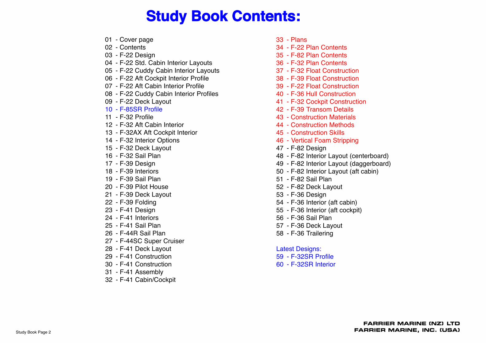
01 - Cover page02 - Contents03 - F-22 Design04 - F-22 Std. Cabin Interior Layouts05 - F-22 Cuddy Cabin Interior Layouts06 - F-22 Aft Cockpit Interior Profile07 - F-22 Aft Cabin Interior Profile08 - F-22 Cuddy Cabin Interior Profiles09 - F-22 Deck Layout10 - F-85SR Profile11 - F-32 Profile12 - F-32 Aft Cabin Interior13 - F-32AX Aft Cockpit Interior14 - F-32 Interior Options15 - F-32 Deck Layout16 - F-32 Sail Plan17 - F-39 Design18 - F-39 Interiors19 - F-39 Sail Plan20 - F-39 Pilot House21 - F-39 Deck Layout22 - F-39 Folding23 - F-41 Design24 - F-41 Interiors25 - F-41 Sail Plan26 - F-44R Sail Plan27 - F-44SC Super Cruiser28 - F-41 Deck Layout29 - F-41 Construction30 - F-41 Construction31 - F-41 Assembly32 - F-41 Cabin/Cockpit
33 - Plans34 - F-22 Plan Contents35 - F-82 Plan Contents36 - F-32 Plan Contents37 - F-32 Float Construction38 - F-39 Float Construction39 - F-22 Float Construction40 - F-36 Hull Construction41 - F-32 Cockpit Construction42 - F-39 Transom Details43 - Construction Materials44 - Construction Methods45 - Construction Skills46 - Vertical Foam Stripping47 - F-82 Design48 - F-82 Interior Layout (centerboard)49 - F-82 Interior Layout (daggerboard)50 - F-82 Interior Layout (aft cabin)51 - F-82 Sail Plan52 - F-82 Deck Layout53 - F-36 Design54 - F-36 Interior (aft cabin)55 - F-36 Interior (aft cockpit)56 - F-36 Sail Plan57 - F-36 Deck Layout58 - F-36 Trailering
Latest Designs:59 - F-32SR Profile60 - F-32SR Interior
FARRIER MARINE (NZ) LTD
FARRIER MARINE, INC. (USA)
Study Book Contents:

®
22
FARRIER F-22
Study Book Page 3
FARRIER F-22
The F-22 is a brand new design that is being developed in New Zealand by Farrier Marine (NZ) Ltd. It will be available in several versions, a full cabin cruising version with either an aft cockpit or aft cabin, and a cuddy cabin version, also with aft cockpit or aft cabin options.
It uses the third generation Farrier Folding System, with externally mounted beams, increasing the interior room significantly. This gives a very spacious feeling to the cabin, and makes the forward double berth area noticeably roomier than even the F-24 design.
Rig is very simple, with rotating mast, all synthetic shrouds, and carbon fiber chainplates - turnbuckles and all metal parts have been eliminated wherever possible.
Only three sails are standard, for simplicity and ease of use, these being main, jib, and a larger screacher. Mainsail is boomless, to save both weight and cost (and sore heads), while the longer luff of the boomless main is more efficient, and gives a lower center of effort.
The aft cockpit is very long and a little wider than earlier designs, for a more spacious feel. The usual cockpit bridge is to be eliminated by some careful engineering, and replaced by a removable compression strut for when needed (such as racing). This leaves the aft mounted traveler as the only obstacle across the cockpit, but one that is well out of the way.
Daggerboard or centerboard options are available, the daggerboard being the simplest and most efficient option, its case also helping to support the mast. The centerboard can be more convenient, its offset case taking up less room in the cabin, plus it will kick back should it hit bottom.
Directional control will be via the latest transom mounted retractable daggerboard rudder system, as recently developed for the F-82, for maximum efficiency and simplicity.
An outboard of 4 to 8 HP is recommended, and this is mounted on an offset bracket, forward of the stern, to minimize cavitation.
Down below, there will be standing headroom under the large pop-top. which can also slide forward for quick cabin access, or have the aft end only lifted to act as a dodger.
The standard boat can sleep four, with one double berth forward and a single berth on each side of the main cabin.
The cabin sides have been moved outboard to be more parallel to centerline than earlier designs, creating more interior room, and also allowing the option of wing berths, which can greatly increase accommodation choices.
The cuddy cabin version has a smaller cabin, but it is still capable of sleeping four at a pinch, with a double in the bow and two quarter berths on each side. A little narrow from waist down (16 - 18" wide), but still usable for most. An additional wide single berth can also be setup under the cockpit floor, or the aft cabin option can be used.
The cuddy cabin's accommodation can be greatly increased by setting up an optional Bimini top, which can then be fully closed in around the cockpit coamings to give a large sheltered living area that can easily seat 6 - 8, with even enough room left over for a picnic table.
Galley can be fixed (at the cost of berth space), or removable. Head can be located forward to one side, and a full width curtain across cabin center can give basic privacy when needed.
Basic Dimensions:
L.O.A...................................... 22' 10" (6.96m)B.O.A..................................... 18' 1" (5.51m)Folded beam........................... 8' 2 1/2" (2.5m)Approx. bare weight .............. 1300 - 1500lbs (590 - 680kg) (depends on model)Float displacement..................3056lbs (1390kg)F-22 sail area (main & jib)...... 325sq.ft (30.15sq.m.) F-22R sail area (main & jib).... 386sq.ft (35.86sq.m.) F-22 mast height..................... 31' (9.4m)F-22R mast height.................. 35' 1" (10.7m)Draft (board up)...................... 12" (0.31m)Draft (board down).................. 4' 11" (1.51m)Interior headroom ...................5' 2" (1.58m) With optional "pop top"........... 6' 2" (1.88m)Main cabin width......................7' 3" (2.2m)Height on trailer...................... 8' 8" (2.64m)
Availability
The F-22 was initially available in plan form but is now only available in kit form. The kit is still under development, as per F-22 web site, and will come as a 'boat in a box', that can be shipped anywhere around the world. It can be assembled by anyone, or by a local boat builder for those without the time or inclination to do it themselves. Hulls will come in a much bigger box, or, more likely, will be built in several locations by franchised F-22 builders to minimize freight costs.
The key parts such as beams, rudders, daggerboards etc. will all be built by Farrier Marine (NZ) Ltd, for the maximum efficiency, and to ensure a high quality standard. These components will then be shipped in bulk to the various builders as required.
The F-22 Plans have now beendiscontinued to be replaced by the
kit version as per F-22 Websitewww.f-boat.com/pages/trimarans/F-22.html
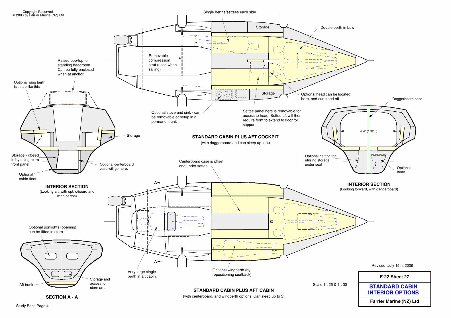
STANDARD CABININTERIOR OPTIONS
F-22 Sheet 27
Farrier Marine (NZ) Ltd
Copyright Reserved © 2006 by Farrier Marine (NZ) Ltd
Scale 1 : 25 & 1 : 30
Revised: July 15th, 2006
Single berths/settees each side
Double berth in bow
Optional stove and sink - can be removable or setup in a permanent unit
Optional head can be located here, and curtained off
STANDARD CABIN PLUS AFT COCKPIT(with daggerboard and can sleep up to 4)
Removable compression strut (used when sailing)
STANDARD CABIN PLUS AFT CABIN(with centerboard, and wingberth options. Can sleep up to 5)
A
A
Settee panel here is removable for access to head. Settee aft will then require front to extend to floor for support
Very large single berth in aft cabin.
Centerboard case is offset and under settee
Storage
Storage
Optional wingberth (by repositioning seatback)
Study Book Page 4
Storage and access to stern area
Daggerboard case
Optional head
4' 4" (1.32m)
SECTION A - A
Aft bunk
Optional portlights (opening) can be fitted in stern
Optional netting for utilzing storage under seat
INTERIOR SECTION(Looking forward, with daggerboard)
Optional centerboard case will go here.
Optional wing berth is setup like this
INTERIOR SECTION(Looking aft, with opt. c/board and
wing berths)
Optional cabin floor
Storage
Raised pop-top for standing headroom Can be fully enclosed when at anchor
Storage - closed in by using extra front panel
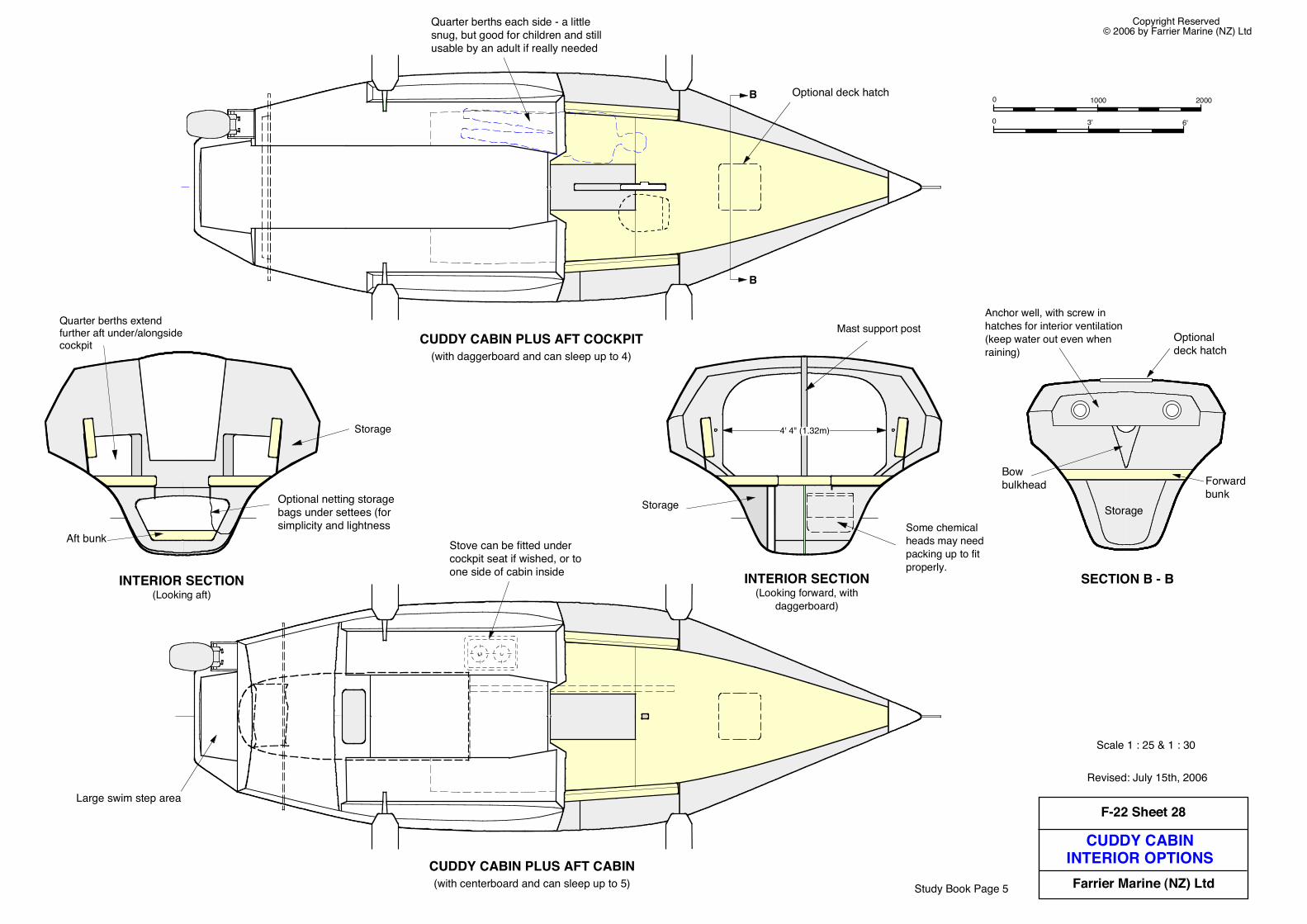
CUDDY CABININTERIOR OPTIONS
F-22 Sheet 28
Farrier Marine (NZ) Ltd
Copyright Reserved © 2006 by Farrier Marine (NZ) Ltd
Scale 1 : 25 & 1 : 30
Revised: July 15th, 2006
CUDDY CABIN PLUS AFT CABIN(with centerboard and can sleep up to 5)
CUDDY CABIN PLUS AFT COCKPIT(with daggerboard and can sleep up to 4)
Stove can be fitted under cockpit seat if wished, or to one side of cabin inside
Large swim step area
0 3' 6'
0 1000 2000
Quarter berths each side - a little snug, but good for children and still usable by an adult if really needed
B
B
Optional deck hatch
Study Book Page 5
Storage
Quarter berths extend further aft under/alongside cockpit
Mast support post
Some chemical heads may need packing up to fit properly.
4' 4" (1.32m)
SECTION B - BINTERIOR SECTION(Looking aft)
INTERIOR SECTION(Looking forward, with
daggerboard)
Optional netting storage bags under settees (for simplicity and lightness
Aft bunk
Storage
Anchor well, with screw in hatches for interior ventilation (keep water out even when raining)
Forward bunk
Storage
Bow bulkhead
Optional deck hatch

INTERIOR LAYOUT& CONSTRUCTION
F-22 Sheet 29
Farrier Marine (NZ) Ltd
Copyright Reserved © 2006 by Farrier Marine (NZ) Ltd
0 3' 6'
0 1000 2000
Scale 1 : 20All interior bulkheads or panels to be as per Sheet 1. Light load furniture vertical panels can be reduced to 6mm thick foam or balsa core with 200gm/6oz cloth each side.
Interior bulkheads/panels to be taped in place with one TAPE 80/3" wide.
Light load panels can be taped in place with a 50/2" wide 200gm/6oz cloth tape
NOTES: Beam bulkheads are angled at 92° to waterline (90° to gunwale line). All other bulkheads are 90° to waterline
Keel must be supported full length between Fwd. Bunk Aft Bulkhead and Cabin Aft Bulkhead, by a curved bunk board on trailer.
Avoid creating any sealed area that cannot be inspected or does not have a drain hole
Revised: May 8th, 2008
6mm (1/4") U-bolt for trailer winch line
Drain holes
Fwd. Bunk Middle Bulkhead (fwd. bow area must be watertight).
Fwd. Bunk Aft Bulkhead (Watertight).
Gunwale line
Optional raised floor (will reduce headroom). Use a center support as detailed below.
Optional portlights in hull side
Option - 1 or 2 100/4" dia. inspection hatches in aft wall of anchor well for ventilation via anchor well hatch
Inspection hatch
Bow Web as per Sheets 16 & 55
DWLStorage
Anchor well
Access hatchAft BeamBulkhead
15755' 2"
19006' 3"
Optional 'Pop-top'
Accesscutout
Fwd. BeamBulkhead
min.25010"Cabin Aft
Bulkhead
Settee front
AFT COCKPIT VERSIONWith Daggerboard
Daggerboard Case Support Web.
Maximum headroom is achieved by walking directly on hull bottom, as is the case with F-24 and F-28. However, a raised floor can have advantages with storage underneath, and a better foot height for seating.
If using the raised floor then the additional layer of A on hull bottom (550 wide - Sheet 17) can be reduced in width to 300/12"
One side of forward bunk top can be removed from here aft (just aft of UD, Step 5, on Sheet 22), for access to optional head. Can also be hinged up
Study Book Page 6
Pre-formed flange on starboard side
10mm foam web (SBM)
Taped to hull with TAPE, 50 to 70mm wide
OPTIONAL FLOOR SUPPORT
Floor
ESTABLISING NORMAL LEVEL
85833 3/4"
DWL
82332 3/8"
72428 1/2"
2068 1/8"
Gunwale line at beam bulkheads
Note that settee has a 1° slope upwards
INTERIOR LAYOUT& CONSTRUCTION
F-22 Sheet 30
Farrier Marine (NZ) LtdCopyright Reserved © 2006 by Farrier Marine (NZ) Ltd
Revised: January 28th, 2008
Scale 1 : 20
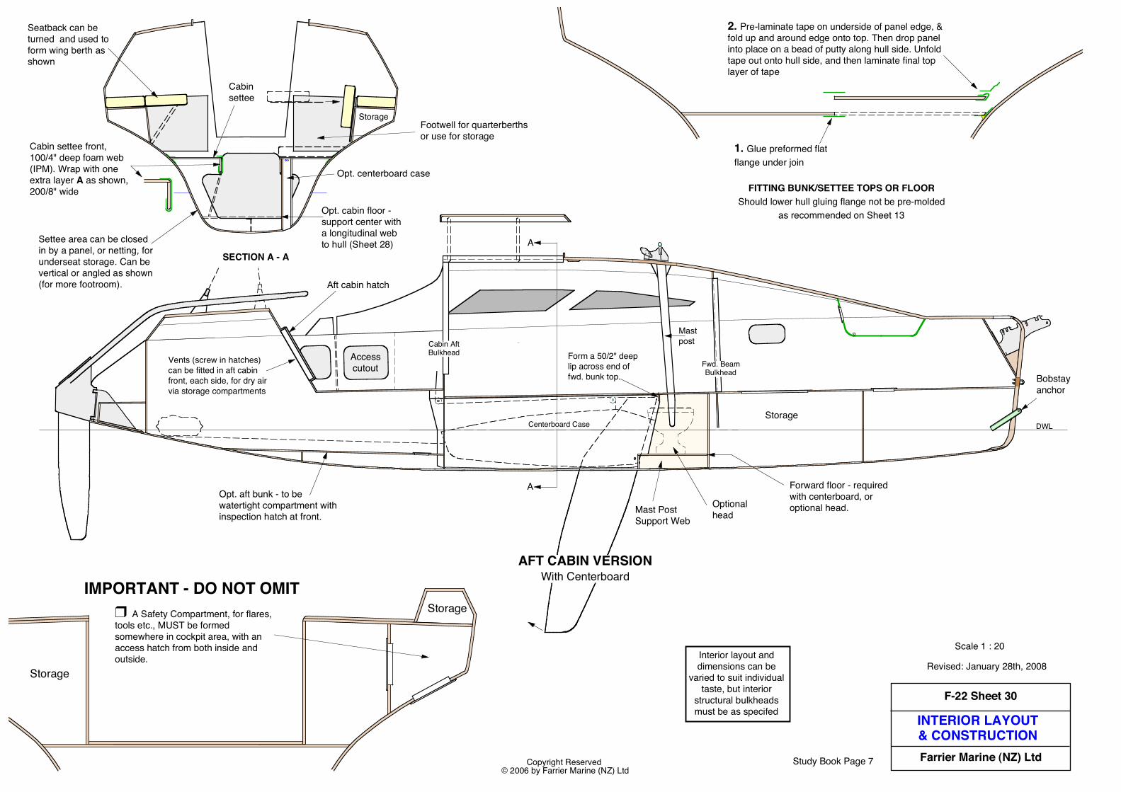
SECTION A - A
Settee area can be closed in by a panel, or netting, for underseat storage. Can be vertical or angled as shown (for more footroom).
Opt. centerboard case
Cabin settee
Footwell for quarterberths or use for storage
Cabin settee front, 100/4" deep foam web (IPM). Wrap with one extra layer A as shown, 200/8" wide
Interior layout anddimensions can be
varied to suit individualtaste, but interior
structural bulkheadsmust be as specifed
Storage
Seatback can be turned and used to form wing berth as shown
Accesscutout
DWLStorage
Vents (screw in hatches) can be fitted in aft cabin front, each side, for dry air via storage compartments
Fwd. BeamBulkhead
Cabin AftBulkhead
Bobstay anchor
Mast post
A
A Forward floor - required with centerboard, or optional head.
Form a 50/2" deep lip across end of fwd. bunk top.
Mast Post Support Web
Optional head
Opt. cabin floor - support center with a longitudinal web to hull (Sheet 28)
Opt. aft bunk - to be watertight compartment with inspection hatch at front.
Aft cabin hatch
AFT CABIN VERSIONWith Centerboard
Centerboard Case
Study Book Page 7
2. Pre-laminate tape on underside of panel edge, & fold up and around edge onto top. Then drop panel into place on a bead of putty along hull side. Unfold tape out onto hull side, and then laminate final top layer of tape
FITTING BUNK/SETTEE TOPS OR FLOORShould lower hull gluing flange not be pre-molded
as recommended on Sheet 13
1. Glue preformed flat flange under join
❒ A Safety Compartment, for flares, tools etc., MUST be formed somewhere in cockpit area, with an access hatch from both inside and outside.
Storage
StorageIMPORTANT - DO NOT OMIT
INTERIOR LAYOUT& CONSTRUCTION
F-22 Sheet 31
Farrier Marine (NZ) LtdCopyright Reserved © 2006 by Farrier Marine (NZ) Ltd
DWL
Aft BeamBkhd.
Accesscutout
CuddyCabin
Bulkhead
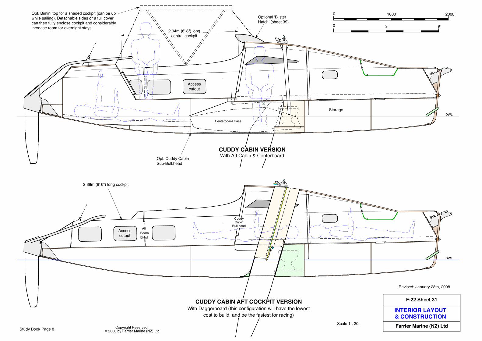
Scale 1 : 20
0 3' 6'
0 1000 2000
CUDDY CABIN AFT COCKPIT VERSIONWith Daggerboard (this configuration will have the lowest
cost to build, and be the fastest for racing)
2.88m (9' 6") long cockpit
Accesscutout
DWLStorage
Centerboard Case
2.04m (6' 8") longcentral cockpit
Opt. Cuddy Cabin Sub-Bulkhead
Opt. Bimini top for a shaded cockpit (can be up while sailing). Detachable sides or a full cover can then fully enclose cockpit and considerably increase room for overnight stays
CUDDY CABIN VERSIONWith Aft Cabin & Centerboard
Optional 'Blister Hatch' (sheet 39)
Revised: January 28th, 2008
Study Book Page 8
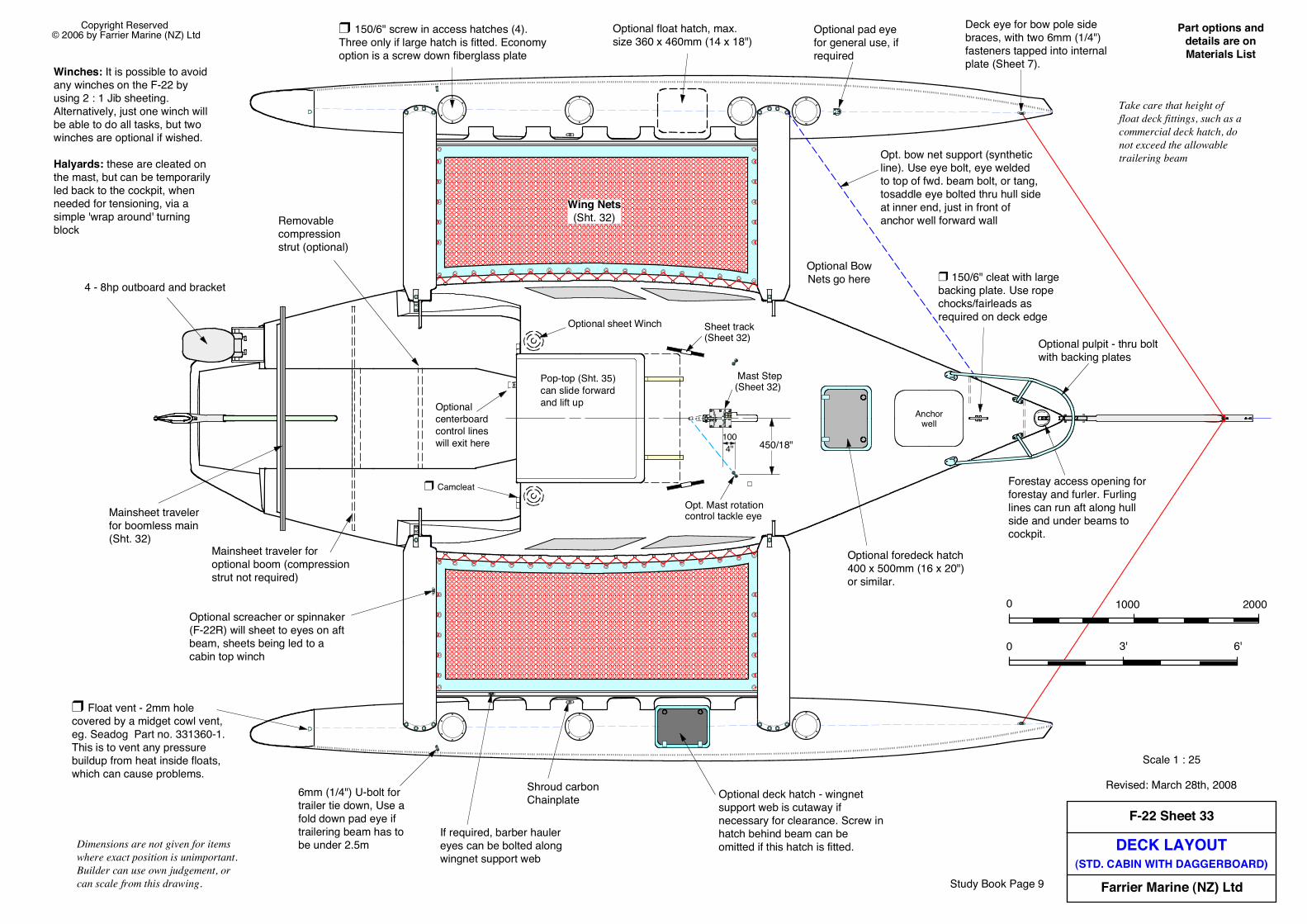
DECK LAYOUT(STD. CABIN WITH DAGGERBOARD)
F-22 Sheet 33
Farrier Marine (NZ) Ltd
Copyright Reserved © 2006 by Farrier Marine (NZ) Ltd
Scale 1 : 25
Optional pulpit - thru bolt with backing plates
Optional sheet Winch
Mainsheet traveler for boomless main (Sht. 32)
Dimensions are not given for items where exact position is unimportant. Builder can use own judgement, or can scale from this drawing.
Shroud carbon Chainplate
Optional foredeck hatch 400 x 500mm (16 x 20") or similar.
Revised: March 28th, 2008
❒ 150/6" screw in access hatches (4). Three only if large hatch is fitted. Economy option is a screw down fiberglass plate
If required, barber hauler eyes can be bolted along wingnet support web
Optional float hatch, max. size 360 x 460mm (14 x 18")
Part options anddetails are onMaterials List
Forestay access opening for forestay and furler. Furling lines can run aft along hull side and under beams to cockpit.
Optional screacher or spinnaker (F-22R) will sheet to eyes on aft beam, sheets being led to a cabin top winch
Optional BowNets go here
Mast Step (Sheet 32)
❒ 150/6" cleat with large backing plate. Use rope chocks/fairleads as required on deck edge
Removable compression strut (optional)
Deck eye for bow pole side braces, with two 6mm (1/4") fasteners tapped into internal plate (Sheet 7).
❒ Float vent - 2mm hole covered by a midget cowl vent, eg. Seadog Part no. 331360-1. This is to vent any pressure buildup from heat inside floats, which can cause problems.
Optional deck hatch - wingnet support web is cutaway if necessary for clearance. Screw in hatch behind beam can be omitted if this hatch is fitted.
Anchorwell
Optional pad eye for general use, if required
❒ Camcleat
Wing Nets(Sht. 32)
Sheet track (Sheet 32)
Winches: It is possible to avoid any winches on the F-22 by using 2 : 1 Jib sheeting. Alternatively, just one winch will be able to do all tasks, but two winches are optional if wished.
Halyards: these are cleated on the mast, but can be temporarily led back to the cockpit, when needed for tensioning, via a simple 'wrap around' turning block
Take care that height of float deck fittings, such as a commercial deck hatch, do not exceed the allowable trailering beam
Mainsheet traveler for optional boom (compression strut not required)
Optional centerboard control lines will exit here
4 - 8hp outboard and bracket
Pop-top (Sht. 35) can slide forward and lift up
0 1000 2000
0 3' 6'
Opt. bow net support (synthetic line). Use eye bolt, eye welded to top of fwd. beam bolt, or tang, tosaddle eye bolted thru hull side at inner end, just in front of anchor well forward wall
6mm (1/4") U-bolt for trailer tie down, Use a fold down pad eye if trailering beam has to be under 2.5m
450/18"1004"
Opt. Mast rotation control tackle eye
Study Book Page 9
85SR
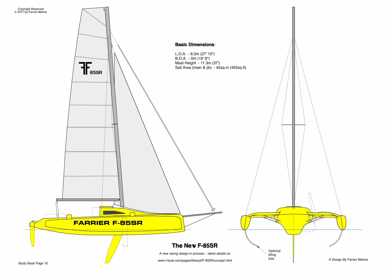
FARRIER F-85SR
A Design By Farrier Marine
Copyright Reserved© 2011 by Farrier Marine
The New F-85SRA new racing design in process - latest details on
www.f-boat.com/pages/News2/F-85SRconcept.htmlStudy Book Page 10
Optional lifting foils
Basic Dimensions:
L.O.A. - 8.5m (27' 10")���B.O.A. - 6m (19' 8")���Mast Height - 11.3m (37')���Sail Area (main & jib) - 42sq.m (455sq.ft)
Copyright Reserved © 2004 by Farrier Marine, Inc F-32 is a trademark of Farrier Marine
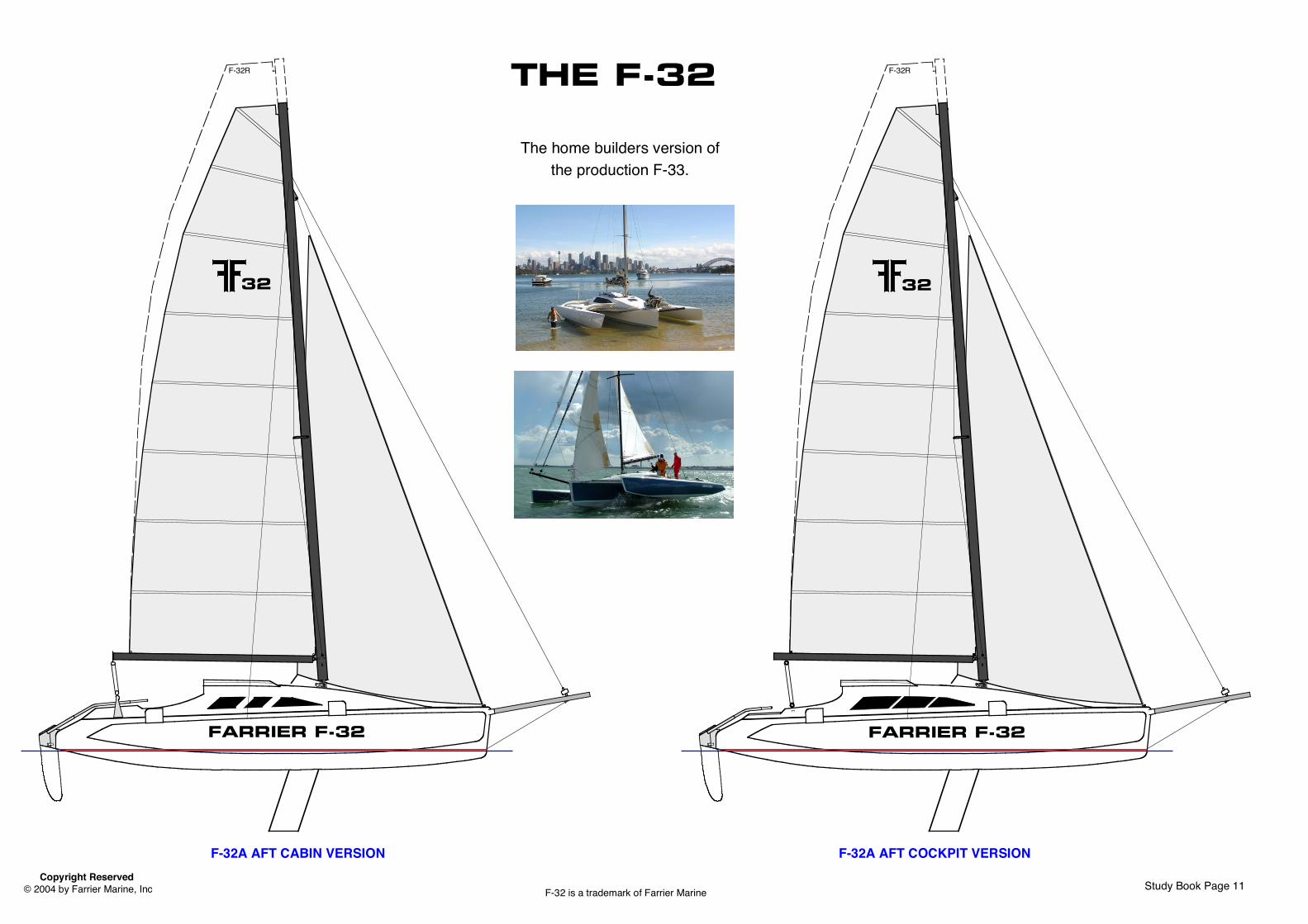
F-32A AFT COCKPIT VERSION
THE F-32
32
F-32R
FARRIER F-32
F-32A AFT CABIN VERSION
32
F-32R
FARRIER F-32
Study Book Page 11
The home builders version ofthe production F-33.
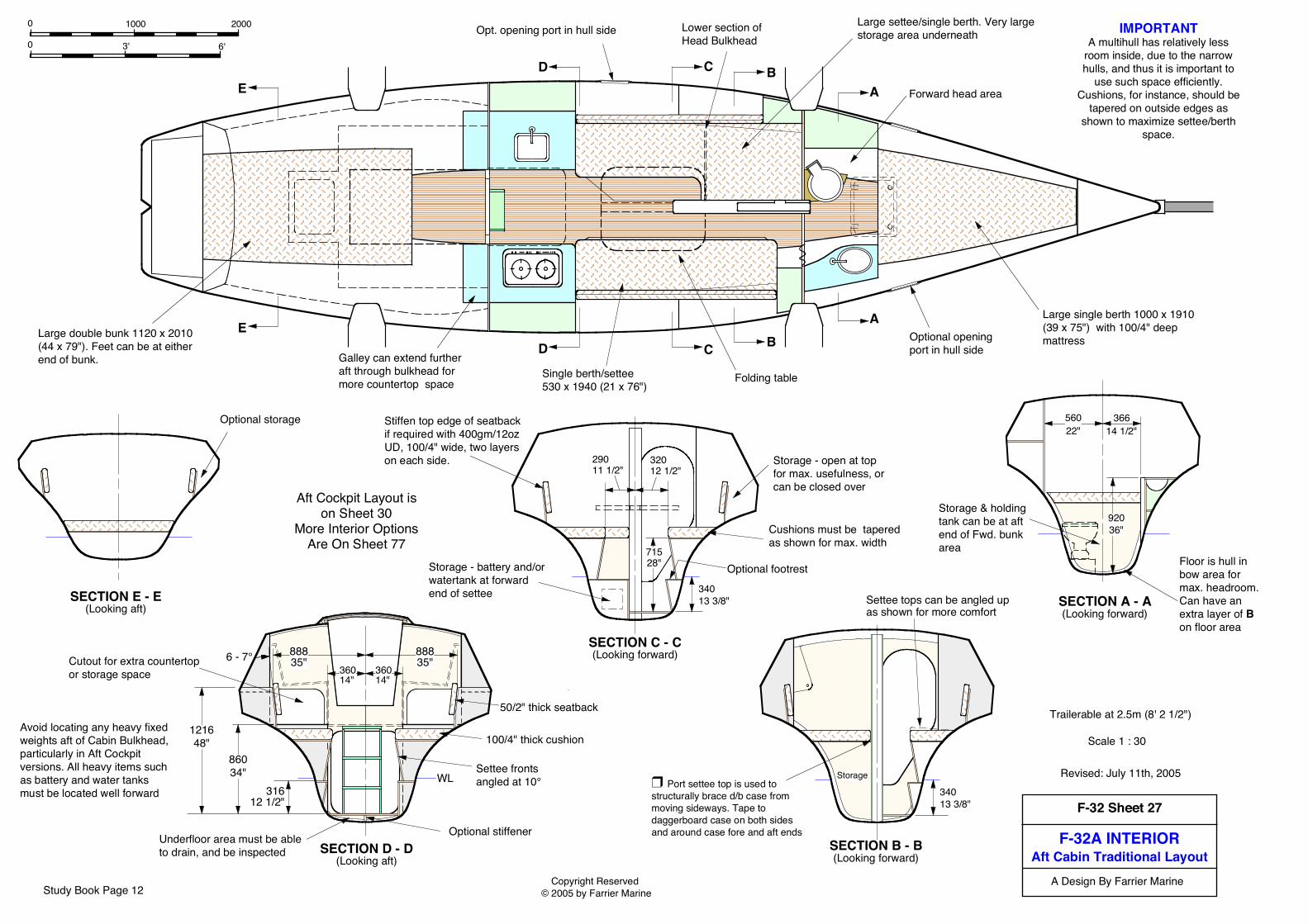
F-32A INTERIORAft Cabin Traditional Layout
F-32 Sheet 27
A Design By Farrier MarineCopyright Reserved © 2005 by Farrier Marine
Scale 1 : 30
D C BA
D C BA
E
E
IMPORTANTA multihull has relatively less
room inside, due to the narrowhulls, and thus it is important to
use such space efficiently.Cushions, for instance, should be
tapered on outside edges asshown to maximize settee/berth
space.
Revised: July 11th, 2005
Trailerable at 2.5m (8' 2 1/2")
Aft Cockpit Layout ison Sheet 30
More Interior OptionsAre On Sheet 77
SECTION A - A(Looking forward)
Storage - open at top for max. usefulness, or can be closed over
SECTION C - C(Looking forward)
Storage - battery and/or watertank at forward end of settee
Cushions must be tapered as shown for max. width
SECTION B - B(Looking forward)
Single berth/settee 530 x 1940 (21 x 76")
Optional opening port in hull side
Stiffen top edge of seatback if required with 400gm/12oz UD, 100/4" wide, two layers on each side.
Large double bunk 1120 x 2010 (44 x 79"). Feet can be at either end of bunk.
SECTION E - E(Looking aft)
Optional storage
Storage & holding tank can be at aft end of Fwd. bunk area
Forward head area
92036"
36614 1/2"
56022"
Storage
Opt. opening port in hull side
Folding table
Large settee/single berth. Very large storage area underneath
Avoid locating any heavy fixed weights aft of Cabin Bulkhead, particularly in Aft Cockpit versions. All heavy items such as battery and water tanks must be located well forward
Large single berth 1000 x 1910 (39 x 75") with 100/4" deep mattress
34013 3/8"
Optional footrest
29011 1/2"
32012 1/2"
34013 3/8"
SECTION D - D(Looking aft)
Underfloor area must be able to drain, and be inspected
6 - 7°
121648"
WL
100/4" thick cushion
88835"
36014"
36014"
88835"
Settee fronts angled at 10°
50/2" thick seatback
Optional stiffener
31612 1/2"
86034"
Cutout for extra countertop or storage space
71528" Floor is hull in
bow area for max. headroom. Can have an extra layer of B on floor area
0 3' 6'
0 1000 2000
❒ Port settee top is used to structurally brace d/b case from moving sideways. Tape to daggerboard case on both sides and around case fore and aft ends
Settee tops can be angled up as shown for more comfort
Galley can extend further aft through bulkhead for more countertop space
Lower section of Head Bulkhead
Study Book Page 12

F-32AX INTERIORAft Cockpit Layout
F-32 Sheet 30
A Design By Farrier MarineCopyright Reserved © 2005 by Farrier Marine
SECTION A - A(Looking forward)
292 (11 1/2")
42016 1/2"
Storage
SECTION D - D(Looking forward)
SECTION E - E(Looking Aft)
Scale 1 : 30
Storage - best open at top for max. usefulness
Storage - battery location
Underfloor area must be able to drain, and be inspected
Cutout for extra countertop/storage space
Cutout if required for quarter berth, with matching recess formed into cockpit floor
Two burner stove
Storage
Optional hanging locker can extend to roof
Dinette can sit 4, and can convert to double
Separate head/shower area, entered from fwd. cabin
Large single berth 1140 x 1910 (45 x 75" (shown using 100/4" deep mattress). Can convert to larger double by extending aft
Single berth 560 x 208022 x 82"
E D C BA
E D C B
Optional opening port in hull side
Optional opening port
1700 - 180067 - 71"
Chart table with storage underneath or Hanging locker
An optional aft berth 1000 x 2200 (39 x 86") can be fitted under cockpit
2010/79"
6 - 7°
Stiffen top edge if required with 400gm/12oz UD, 100/4" wide, two layers on each side
IMPORTANTA multihull has relatively less
room inside, due to the narrowhulls, and thus it is important to
use such space efficiently.Cushions, for instance, shouldbe tapered on outside edges
as shown to maximizesettee/berth space.560
22"
Optional opening port
Head should sit on removable plate for access to bilge and or shower pump area Revised: July 11th, 2005
Trailerable at 9' 6" - 9' 8" (2.9 - 2.95m)
More Interior OptionsAre On Sheet 77
Avoid locating any heavy fixed weights aft of Cabin Bulkhead, particularly in Aft Cockpit versions. All heavy items such as battery and water tanks must be located well forward
1730 - 188068 - 74"
42016 1/2"
WL
Optional stiffener
111043 3/4"
111043 3/4"
50019 3/4"
58223"
119047"
34013 3/8"
71528"
SECTION C - C(Looking forward)
Storage, Ice Box, battery and watertank are all located under fwd. end of dinette.
91036" Sink
Cushions must be tapered as shown for max. width
50019 3/4"
34013 3/8"
SECTION B - B(Looking forward)
Floor is hull in bow area for max. headroom. Can have an extra layer of B on floor area
A
Storage and holding tank behind hereRemovable
StepWL
0 3' 6'
0 1000 2000
225/9"
Head floor taped to d/b case on both sides for extra case support.
Optional foot rest
Study Book Sheet 13
Scale 1 : 30
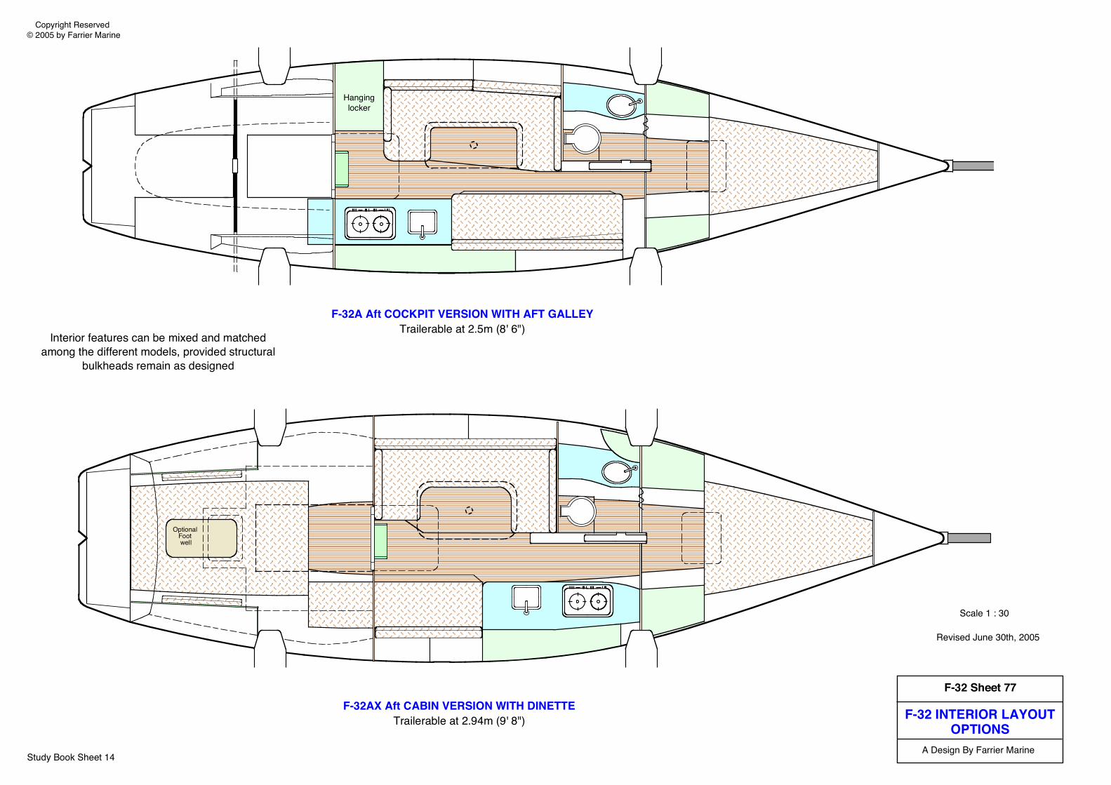
Interior features can be mixed and matchedamong the different models, provided structural
bulkheads remain as designed
Optional Foot well
F-32AX Aft CABIN VERSION WITH DINETTETrailerable at 2.94m (9' 8")
F-32A Aft COCKPIT VERSION WITH AFT GALLEYTrailerable at 2.5m (8' 6")
Hanginglocker
Revised June 30th, 2005
Study Book Sheet 14
F-32 INTERIOR LAYOUTOPTIONS
F-32 Sheet 77
A Design By Farrier Marine
Copyright Reserved © 2005 by Farrier Marine
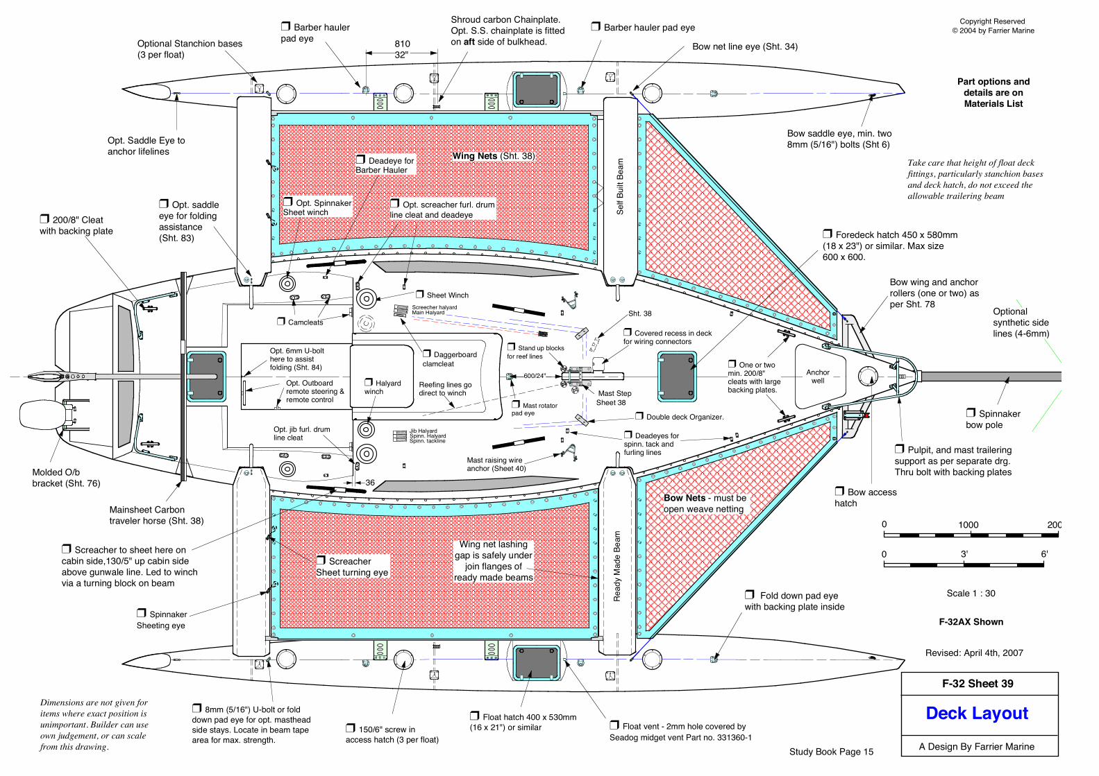
Deck Layout
Copyright Reserved © 2004 by Farrier Marine
A Design By Farrier Marine
F-32 Sheet 39
Scale 1 : 30
Optional Stanchion bases (3 per float)
❒ Fold down pad eye with backing plate inside
Take care that height of float deck fittings, particularly stanchion bases and deck hatch, do not exceed the allowable trailering beam
Opt. Saddle Eye to anchor lifelines
❒ Pulpit, and mast trailering support as per separate drg. Thru bolt with backing plates
❒ Double deck Organizer.
❒ Sheet Winch
❒ 200/8" Cleat with backing plate
Mainsheet Carbon traveler horse (Sht. 38)
Dimensions are not given for items where exact position is unimportant. Builder can use own judgement, or can scale from this drawing.
Shroud carbon Chainplate. Opt. S.S. chainplate is fitted on aft side of bulkhead.
❒ Spinnaker bow pole
❒ Camcleats
Bow wing and anchor rollers (one or two) as per Sht. 78
Bow net line eye (Sht. 34)
❒ Deadeyes for spinn. tack and furling lines
Bow saddle eye, min. two 8mm (5/16") bolts (Sht 6)
❒ Foredeck hatch 450 x 580mm (18 x 23") or similar. Max size 600 x 600.
Revised: April 4th, 2007
0 1000 2000
0 3' 6'
❒ 150/6" screw in access hatch (3 per float)
❒ Barber hauler pad eye
❒ Barber hauler pad eye
❒ Float hatch 400 x 530mm (16 x 21") or similar
❒ Mast rotator pad eye
Opt. jib furl. drum line cleat
Mast raising wire anchor (Sheet 40)
Jib Halyard Spinn. HalyardSpinn. tackline
Part options anddetails are onMaterials List
❒ Covered recess in deck for wiring connectors
❒ Bow access hatch
❒ Screacher to sheet here on cabin side,130/5" up cabin side above gunwale line. Led to winch via a turning block on beam
Bow Nets - must be open weave netting
Main Halyard Screecher halyard
❒ Stand up blocks for reef lines
A
A
❒ Halyard winch
Reefing lines go direct to winch
Optional synthetic side lines (4-6mm)
81032"
Sht. 38
❒ Daggerboard clamcleat
❒ 8mm (5/16") U-bolt or fold down pad eye for opt. masthead side stays. Locate in beam tape area for max. strength.
36
❒ Screacher Sheet turning eye
❒ Opt. saddle eye for folding assistance (Sht. 83)
❒ Opt. Spinnaker Sheet winch
Wing Nets (Sht. 38)❒ Deadeye for Barber Hauler
❒ Opt. screacher furl. drum line cleat and deadeye
❒ Spinnaker Sheeting eye
Mast Step Sheet 38
❒ One or two min. 200/8" cleats with large backing plates.
AnchorwellOpt. Outboard
remote steering & remote control
F-32AX Shown
❒ Float vent - 2mm hole covered by Seadog midget vent Part no. 331360-1
Molded O/b bracket (Sht. 76)
Opt. 6mm U-bolt here to assist folding (Sht. 84)
600/24"
Read
y M
ade
Beam
Self
Built
Beam
Wing net lashinggap is safely under
join flanges ofready made beams
Study Book Page 15
32
F-32
R
F-32
Copy
right
Res
erve
d ©
200
4 by
Far
rier M
arin
eF-
32 is
a tr
adem
ark
of F
arrie
r Mar
ine
May
13t
h, 2
008
Scal
e 1
: 50
A De
sign
By F
arrie
r Mar
ine
www.
f-boa
t.com
SAIL
PLA
N
Luff
1264
041
.46
1123
536
.86'
1258
041
.27'
1430
546
.93'
7410
24.3
2'13
440
44.0
9'15
905
52.1
8'
956/
3.14
'
Sailm
aker
shou
ld b
e aw
are
that
the
load
ings
on
a M
ultih
ull's
sails
ar
e co
nsid
erab
ly h
ighe
r th
an a
n eq
uiva
lent
m
onoh
ull d
ue to
the
muc
h gr
eate
r max
imum
st
abili
ty a
s fol
low
s:F-
32: 5
6,00
0 ft.
lbs
F-32
X: 5
7,50
0 ft.
lbs
min
. 70
2 3/
4" HEAD
DET
AIL
200/
8"
Mas
t hei
ght f
rom
wat
erlin
e F-
32 -
14.8
m/4
8' 7
"F-
32R
- 15
.6m
/51'
2" (
Car
bon
mas
t onl
y)M
ains
ail
Jib
Scre
ache
r
Asym
. Spi
nn.
Stor
m J
ib
R M
ain
R As
ym.
Sail
Leac
h12
930
42.4
2'98
6032
.35'
1112
036
.5'
1235
540
.53
5820
19.1
'13
680
44.8
8'13
955
45.7
8'
Foot
4210
13.8
1'42
5013
.94
7690
25.2
3'94
1030
.936
8512
.142
1013
.81'
9560
31.4
'
Area
37.9
sq.m
.40
8sq.
ft21
.3sq
.m23
0sq.
ft43
.88s
q.m
473s
q.ft
89sq
.m96
0sq.
ft10
.6sq
.m11
4sq.
ft42
sq.m
452s
q.ft.
111s
q.m
1198
s q.ft
Addi
tiona
l Inf
o
Mas
t len
gths
F-32
- 13
.2m
/43.
3'
F-32
R -
14.0
m/4
6' (c
arbo
n)
NOTE
S:Sa
ilclo
th w
eigh
t to
suit
mat
eria
l use
d, a
nd a
vera
ge
wind
stre
ngth
in a
rea
saile
d.
Mai
nsai
l to
have
3 s
ets
of re
efpo
ints
and
Cun
ning
ham
ey
e fit
ted.
Bat
ten
Car/t
rack
sys
tem
reco
mm
ende
d fo
r m
ains
ail lu
ff on
cru
isers
. Hea
d lo
ads
are
very
hig
h a n
d ex
tra p
reca
utio
ns m
ust b
e ta
ken
to p
reve
nt p
ull o
ut w
ith
bolt
rope
s.
Clas
s em
blem
loca
ted
and
sized
as
show
n.Ji
b to
hav
e 4
leac
h ba
ttens
pl a
ced
at e
qua l
dist
ance
on
leac
h, u
nles
s ro
ller f
urlin
g. H
anks
are
to b
e fo
r 7 -
8mm
(9
/32"
to 5
/16"
) wire
Tellt
ales
to b
e fit
ted
to a
ll sai
ls.Sc
reac
her h
as a
min
. 5m
m/7
/32"
wir e
or 9
mm
/3/8
" Ke
vlar l
uff a
nd is
a fu
rling
mul
ti- p
urpo
se s
ail s
et fr
om
bow
pol
e. C
an b
e us
ed to
win
dwar
d in
light
airs
(up
to 7
kn
ots
inst
ead
of g
enoa
) an d
for r
each
ing
or ru
nnin
g in
lig
ht to
hea
vy w
inds
. Luf
f mus
t be
tight
(2 :
1 ha
lyard
re
com
men
ded)
for w
indw
a rd
use.
Tac
king
is
acco
mpl
ished
by
furli
ng d
u rin
g ta
ck.
The
flush
Squ
aret
op M
ain
has
prov
en to
be
supe
rior t
o al
l oth
er c
onve
ntio
nal f
ull b
atte
n m
ains
on
iden
tical
bo
ats.
It w
ill gi
ve th
e sa
me
perfo
rman
ce a
s a
mas
t 5-7
%
high
er b
ut w
ith le
ss w
eigh
t and
win
dage
alo
ft.
1090
/3.5
8'
(mas
thea
d)
Max
. foo
t rou
nd
155m
m (6
")
350
(14"
)
90 (3
1/2
")
50 (2
")
262
(10
1/4"
)®
720
(28"
)Mak
e wi
der i
f 2 :
1 ha
lyar
d is
bein
g us
ed
F-32
She
et 4
9
Mas
thea
d sp
inna
ker
or C
ode
0 op
tiona
l on
F-3
2R (C
ode
0 m
ay n
eed
extra
sid
e st
ays)
Reco
mm
ende
d re
ef
poin
ts (d
ashe
d lin
es
are
for F
-32R
)Fo
rest
ay is
12.
18m
(3
9' 1
1") p
in to
pin
. Re
duce
by
45m
m/1
3/4
" w
ith M
arst
rom
mas
ts to
al
low
for t
op s
hack
le in
th
eir s
yste
m
13.4
m (4
3.96
') bo
w pi
n - s
heav
e pi
n
Batte
n
1293
042
.42'
1250
4.1'
max
1655
5.4'
max
SAIL
NO
____
Aft C
ockp
itSh
eetin
g
DO N
OT
INCR
EASE
MAI
NSAI
LRO
ACH
OR
HEAD
WID
THSo
me
sailm
aker
s m
ay tr
y to
reco
mm
end
this,
and
if s
o ta
ke y
our
busin
ess
else
wher
e. P
erfo
rman
ce w
illno
t be
impr
oved
to a
ny d
egre
e bu
t you
will
be th
e on
e le
ft wi
th th
e ha
ndlin
gpr
oble
ms
that
will
resu
lt.
Max
. foo
t rou
nd
310m
m (1
2")
FA
RR
IER
F-3
2
Bolt
Rope
- 8o
z Te
flon
Tape
or
simila
r ove
r 3/8
" min
. to
1/2"
max
. so
lid b
raid
ed ro
pe to
sui
t mas
tSl
ides
- m
ust s
uit m
ast a
nd b
e ex
tra lo
ng (m
in 5
0mm
met
al) o
r do
uble
d at
hea
d ar
ea, t
o pr
even
t 'p
ull o
ut'.
Cuto
ut fo
r ha
lyard
cle
aran
ce
F/gl
ass
rod
inse
rt in
bol
t rop
e, tw
o se
ctio
ns a
t 4"/1
00
long
Study Book Sheet 16
Study Book Page 17
Specifications
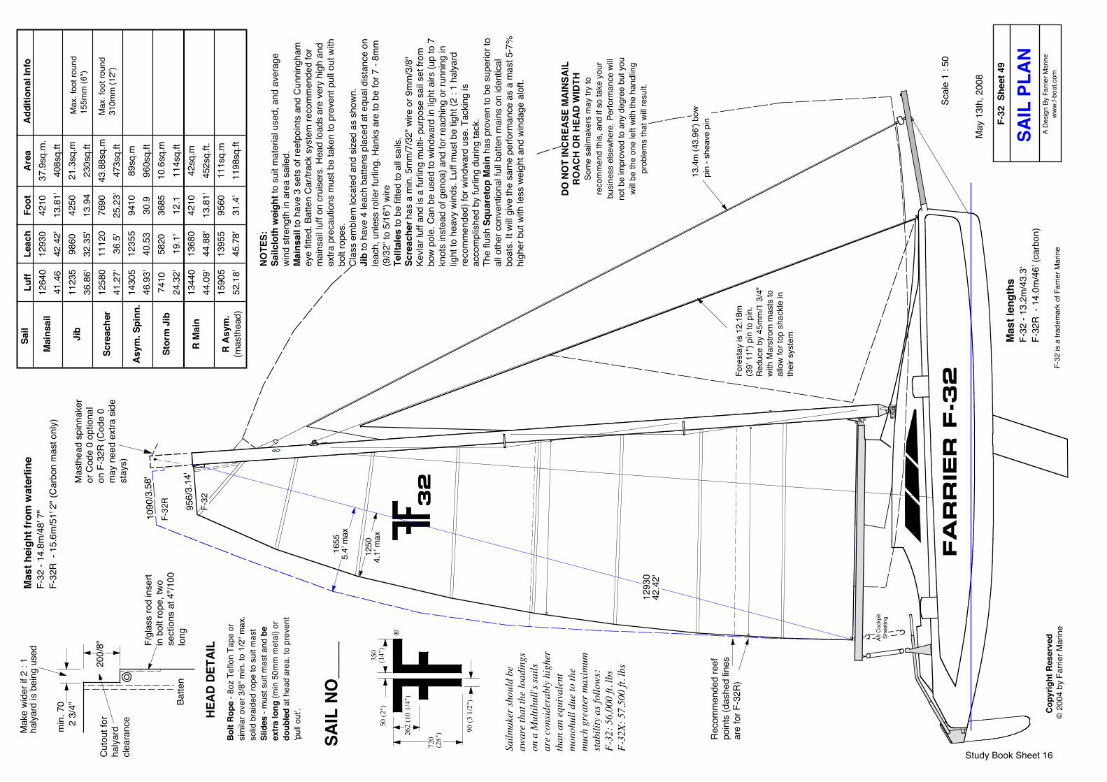
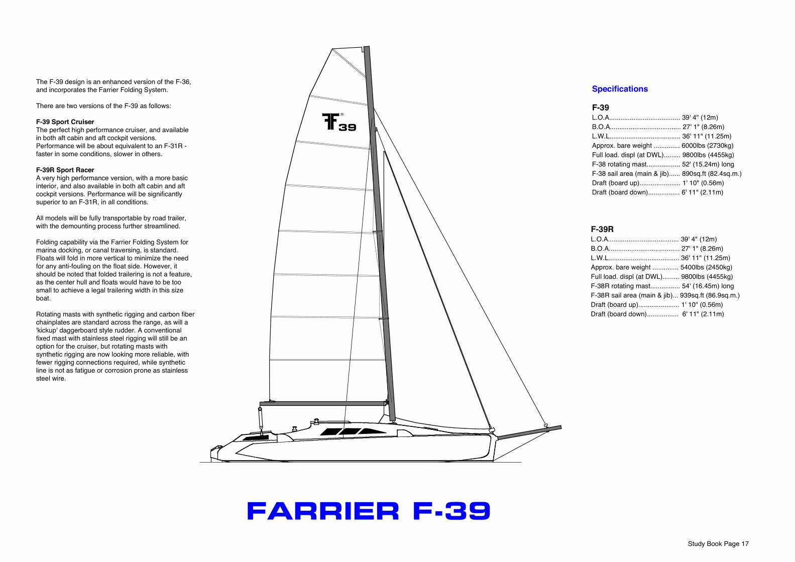
F-39 L.O.A...................................... 39' 4" (12m)B.O.A...................................... 27' 1" (8.26m)L.W.L...................................... 36' 11" (11.25m)Approx. bare weight .............. 6000lbs (2730kg)Full load. displ (at DWL)......... 9800lbs (4455kg)F-38 rotating mast.................. 52' (15.24m) longF-38 sail area (main & jib)...... 890sq.ft (82.4sq.m.) Draft (board up)...................... 1' 10" (0.56m)Draft (board down)................. 6' 11" (2.11m)
F-39RL.O.A...................................... 39' 4" (12m) B.O.A...................................... 27' 1" (8.26m)L.W.L...................................... 36' 11" (11.25m)Approx. bare weight .............. 5400lbs (2450kg)Full load. displ (at DWL)......... 9800lbs (4455kg)F-38R rotating mast................ 54' (16.45m) longF-38R sail area (main & jib)... 939sq.ft (86.9sq.m.) Draft (board up)...................... 1' 10" (0.56m)Draft (board down)................. 6' 11" (2.11m)
®
39
FARRIER F-39
The F-39 design is an enhanced version of the F-36, and incorporates the Farrier Folding System.
There are two versions of the F-39 as follows:
F-39 Sport CruiserThe perfect high performance cruiser, and available in both aft cabin and aft cockpit versions. Performance will be about equivalent to an F-31R - faster in some conditions, slower in others.
F-39R Sport RacerA very high performance version, with a more basic interior, and also available in both aft cabin and aft cockpit versions. Performance will be significantly superior to an F-31R, in all conditions.
All models will be fully transportable by road trailer, with the demounting process further streamlined.
Folding capability via the Farrier Folding System for marina docking, or canal traversing, is standard. Floats will fold in more vertical to minimize the need for any anti-fouling on the float side. However, it should be noted that folded trailering is not a feature, as the center hull and floats would have to be too small to achieve a legal trailering width in this size boat.
Rotating masts with synthetic rigging and carbon fiber chainplates are standard across the range, as will a 'kickup' daggerboard style rudder. A conventional fixed mast with stainless steel rigging will still be an option for the cruiser, but rotating masts with synthetic rigging are now looking more reliable, with fewer rigging connections required, while synthetic line is not as fatigue or corrosion prone as stainless steel wire.
Copy
right
Res
erve
d ©
200
1 by
Ian
Farri
er
F-39
™ IN
TERI
OR
OPT
IONS
AFT
CABI
N FU
LL C
RUIS
ING
INTE
RIO
R(W
ith S
tand
ard
Mai
n Ca
bin
and
optio
nal 'k
ick-
back
' cen
terb
oard
)
F-39
is a
trad
emar
k of
Far
rier M
arin
e
Aft c
abin
dou
ble
berth
, 1.6
m (5
' 3")
wid
e an
d up
to 2
m (6
' 6")
long
, or c
an
be s
etup
as
two
sing
les
each
sid
e.
Sepa
rate
enc
lose
d ba
thro
om w
ith
show
er (6
' to
6' 2
" hea
droo
m).
Pass
agew
ayun
der c
ockp
it
Ice
box
Engi
ne
Din
ette
(sea
ts 4
- 6)
can
be
conv
erte
d to
larg
e do
uble
1.9
4m x
1.4
m (6
' 4" x
4' 7
")
Hang
ing
Lock
er
Storag
e
Storag
e
Storag
e
Storag
e
Two
sing
le/b
erth
s ea
ch s
ide
or
can
be c
onve
rted
into
one
do
uble
, 1.9
6m x
1.2
m (6
' 5" x
4')
AFT
COCK
PIT
CRUI
SIN
G IN
TERI
OR
(With
Lon
ger M
ain
Cab
in a
nd d
agge
rboa
rd)
3.29
m (1
0' 9
") lo
ng
cock
pit -
aft
end
can
be o
pen
or c
lose
d
Sepa
rate
enc
lose
d ba
thro
om w
ith s
how
er
(6' t
o 6'
2" h
eadr
oom
).
Ice
boxDin
ette
(sea
ts 4
- 6)
can
be
conv
erte
d to
larg
e do
uble
2m
x 1
.4m
(6' 6
" x 4
' 7")
Hang
ing
Lock
er
Storag
e
Dou
ble
berth
, 1.9
6m x
1.2
m
(6' 5
" x 4
')
Sette
e be
rth -
1.92
m x
0.6
3m (6
' 4" x
2' 1
")
AFT
COCK
PIT
F-39
R IN
TERI
OR
(With
Sta
ndar
d M
ain
Cabi
n le
ngth
and
dag
gerb
oard
)
Sepa
rate
bat
hroo
m w
ith
show
er
Sette
e be
rths
2m x
0.6
3m
(6' 6
" x 2
' 1")
or la
rger
. Can
be
pipe
ber
ths
and/
or c
onve
rt in
to
uppe
r and
lowe
r bun
ks
2.48
m (8
' 1")
long
co
ckpi
t - a
ft en
d ca
n be
ope
n or
clo
sed
Gal
ley
unit
(rem
ovab
le)
Storag
e
Storag
e
Storag
e
Sette
e be
rth -
1.92
m x
0.6
3m (6
' 4" x
2' 1
")
Stor
age
or o
ptio
nal
quar
ter b
erth
- 2.
0m x
0.
71m
(6' 6
" x 2
' 4")
Larg
e st
orag
e lo
cker
or
extra
cou
nter
top
spac
e
Opt
iona
l out
boar
d (in
wel
l)
Navig
atio
nTa
ble
Navig
atio
nTa
ble
Navig
atio
nTa
ble
Opt
iona
l co
unte
r ex
tens
ion
Study Book Page 18
F-39
She
et 4
9SA
IL P
LAN
A De
sign
By F
arrie
r Mar
ine,
Inc.
All M
etric
Dim
ensio
ns a
re in
Milli
met
res
unle
ss o
ther
wise
spe
cifie
dC
opyr
ight
Res
erve
d ©
200
4 by
Far
rier M
arin
e, In
c.
Scal
e 1
: 56
Revis
ed N
ovem
ber 7
th, 2
004
Fore
stay
is14
080
46.1
9' p
into
pin
Mai
nsai
l
Jib
Scre
ache
r
Asy
m. S
pinn
.
Stor
m J
ib
F-31
R M
ain
Luff
1496
049
.1'
1306
042
.85'
1470
048
.22'
1670
054
.8'
8710
28.5
815
850
52'
NOTE
S:Sa
ilclo
th w
eigh
t to
suit
mat
eria
l use
d, a
nd
aver
age
wind
stre
ngth
in a
rea
saile
d.
Mai
nsai
l to
have
3 s
ets
of re
efpo
ints
and
C
unni
ngha
m e
ye fi
tted.
Bat
ten
Car/t
rack
sys
tem
re
com
men
ded
for m
ains
ail l
uff.
Clas
s em
blem
lo
cate
d an
d siz
ed a
s sh
own.
Jib
to h
ave
4 le
ach
batte
ns p
lace
d at
equ
al
dist
ance
on
leac
h, u
nles
s ro
ller f
urlin
g. If
use
d,
hank
s ar
e to
sui
t hea
dsta
y siz
e.Sc
reac
her h
as a
min
. 6m
m/1
/4" w
ire o
r 10
mm
/3/8
" Kev
lar l
uff a
nd is
a fu
rling
mul
ti-
purp
ose
sail s
et fr
om b
ow p
ole.
Can
be
used
to
wind
ward
in lig
ht a
irs (u
p to
7 k
nots
inst
ead
of
geno
a) a
nd fo
r rea
chin
g or
runn
ing
in lig
ht to
he
avy
wind
s. L
uff m
ust b
e tig
ht (2
: 1
halya
rd
reco
mm
ende
d) fo
r win
dwar
d us
e. T
ackin
g is
acco
mpl
ished
by
furli
ng d
urin
g ta
ck.
The
flush
Squ
aret
op M
ain
has
now
prov
en to
be
sup
erio
r to
all o
ther
con
vent
iona
l ful
l bat
ten
mai
ns o
n id
entic
al b
oats
. It w
ill gi
ve th
e sa
me
perfo
rman
ce a
s a
mas
t 5-7
% h
ighe
r but
with
le
ss w
eigh
t and
win
dage
alo
ft. N
ot a
ll sa
ilmak
ers
have
exp
erie
nce
with
thes
e, a
nd a
sp
ecia
list m
ultih
ull s
ailm
aker
may
be
requ
ired.
Sailm
aker
shou
ld b
e aw
are
that
the
load
ings
on
a M
ultih
ull's
sails
are
co
nsid
erab
ly h
ighe
r tha
n an
equ
ival
ent
mon
ohul
l due
to th
e m
uch
grea
ter
max
imum
stab
ility
(125
,000
ft. lb
s)
400
(16"
)
96 (3
3/4
")
50 (2
")
300
(12"
)
820
(32"
)
HEAD
DET
AIL
850
2.8'
max
. ro
ach
Mas
t hei
ght f
rom
wat
erlin
e F-
39 :
17.
6m/5
7.7'
F-39
R : 1
8.5m
/60.
7'
Sail
Leac
h15
330
50.3
'11
500
37.7
2'12
800
42'
1445
047
.41'
6950
22.8
'16
160
53.0
2'
Foot
5040
16.5
4'47
8015
.68'
9210
30.2
2'11
200
36.7
6'42
0013
.78'
5040
16.5
3'
Area
54.2
sq.m
.58
4sq.
ft28
.2sq
.m30
5sq.
ft61
sq.m
657s
q.ft
121.
8sq.
m13
15sq
.ft14
.55s
q.m
157s
q.ft
59.3
sq.m
639s
q.ft.
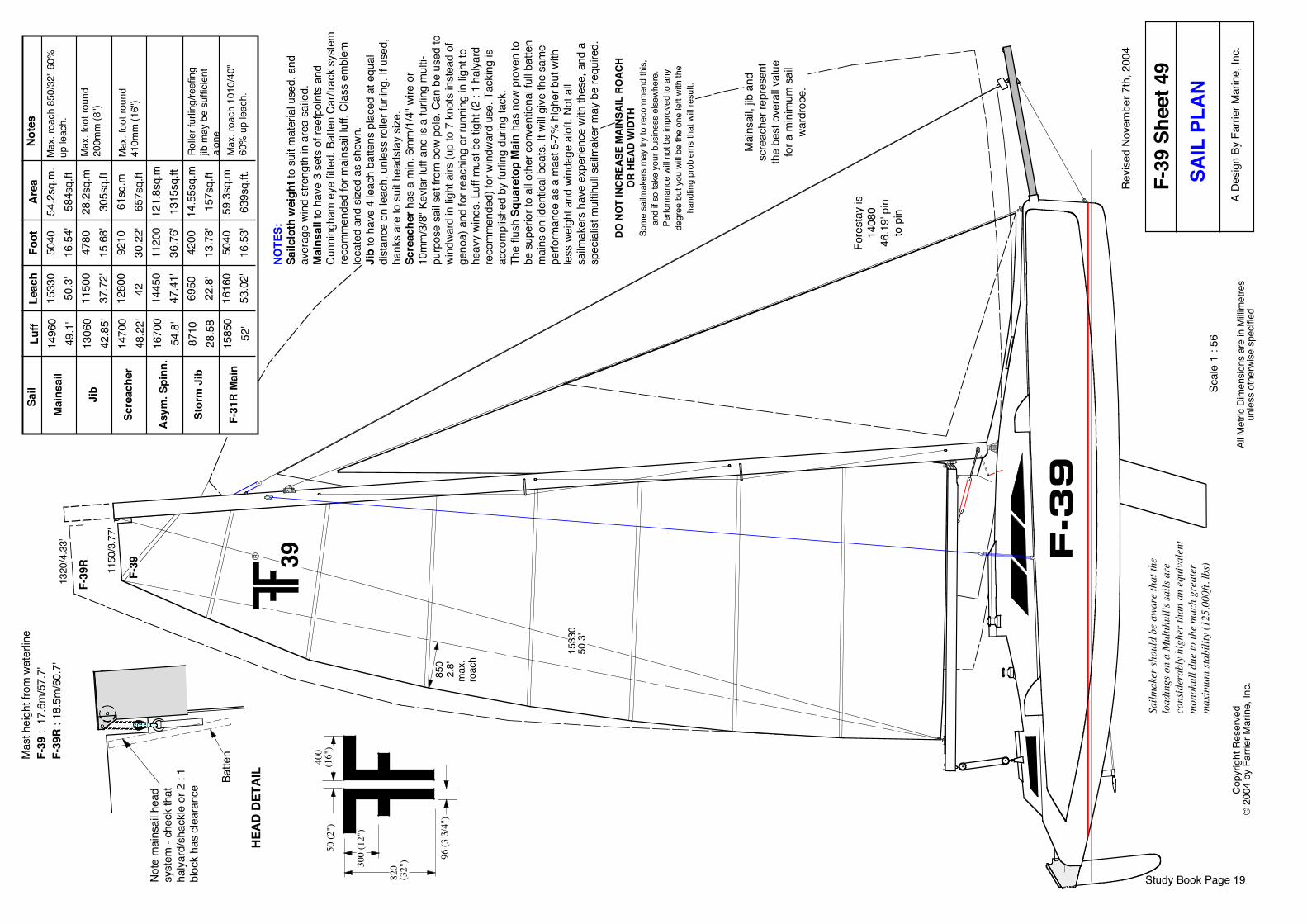
Note
s
Max
. foo
t rou
nd
200m
m (8
")
Max
. foo
t rou
nd
410m
m (1
6")
Max
. roa
ch 8
50/3
2" 6
0%
up le
ach.
Rolle
r fur
ling/
reef
ing
jib m
ay b
e su
ffici
ent
alon
e
Mai
nsai
l, jib
and
scre
ache
r rep
rese
ntth
e be
st o
vera
ll val
uefo
r a m
inim
um s
ail
ward
robe
.
1150
/3.7
7'
1533
050
.3'
1320
/4.3
3'
F-39
R
F-39
® 39
Max
. roa
ch 1
010/
40"
60%
up
leac
h.
DO N
OT
INC
REAS
E M
AINS
AIL
ROAC
HO
R H
EAD
WID
THSo
me
sailm
aker
s m
ay tr
y to
reco
mm
end
this,
and
if so
take
you
r bus
ines
s el
sewh
ere.
Perfo
rman
ce w
ill no
t be
impr
oved
to a
nyde
gree
but
you
will
be th
e on
e le
ft wi
th th
eha
ndlin
g pr
oble
ms
that
will
resu
lt.
Study Book Page 19
F-3
9
Batte
n
Note
mai
nsai
l hea
d sy
stem
- ch
eck
that
ha
lyard
/sha
ckle
or 2
: 1
bloc
k ha
s cl
eara
nce
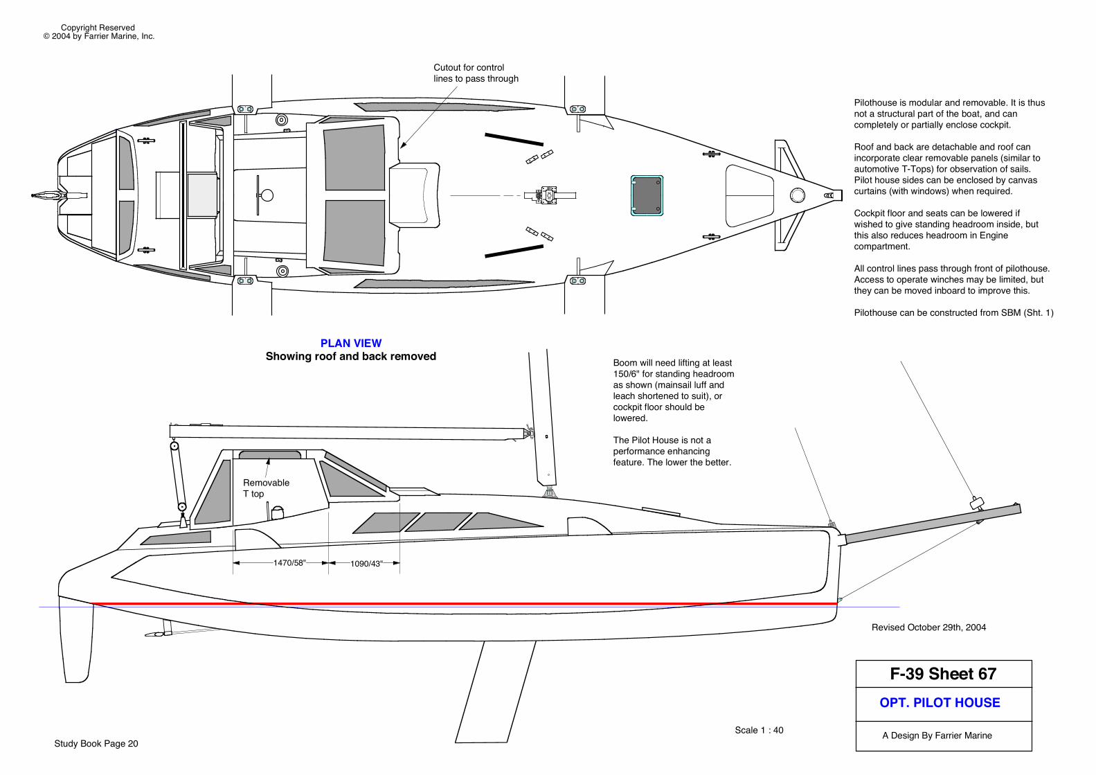
F-39 Sheet 67OPT. PILOT HOUSE
A Design By Farrier Marine
Copyright Reserved © 2004 by Farrier Marine, Inc.
Study Book Page 20Scale 1 : 40
Revised October 29th, 2004
Pilothouse is modular and removable. It is thus not a structural part of the boat, and can completely or partially enclose cockpit.
Roof and back are detachable and roof can incorporate clear removable panels (similar to automotive T-Tops) for observation of sails. Pilot house sides can be enclosed by canvas curtains (with windows) when required.
Cockpit floor and seats can be lowered if wished to give standing headroom inside, but this also reduces headroom in Engine compartment.
All control lines pass through front of pilothouse. Access to operate winches may be limited, but they can be moved inboard to improve this.
Pilothouse can be constructed from SBM (Sht. 1)
PLAN VIEWShowing roof and back removed Boom will need lifting at least
150/6" for standing headroom as shown (mainsail luff and leach shortened to suit), or cockpit floor should be lowered.
The Pilot House is not a performance enhancing feature. The lower the better.
Removable T top
1090/43"1470/58"
Cutout for control lines to pass through
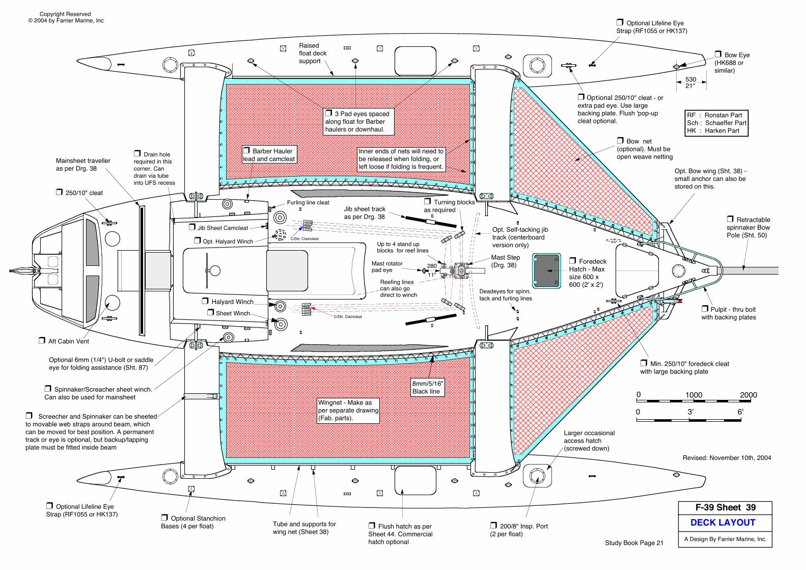
DECK LAYOUTF-39 Sheet 39
A Design By Farrier Marine, Inc.
Copyright Reserved © 2004 by Farrier Marine, Inc
❒ Bow Eye (HK688 or similar)
❒ 200/8" Insp. Port (2 per float)
❒ Optional Lifeline Eye Strap (RF1055 or HK137)
Revised: November 10th, 2004
❒ Foredeck Hatch - Max size 600 x 600 (2' x 2')
❒ Optional StanchionBases (4 per float)
Jib sheet trackas per Drg. 38
❒ Turning blocks as required
Mast Step(Drg. 38)
❒ Sheet Winch
C/Db. Clamcleat
❒ Jib Sheet Camcleat
❒ Spinnaker/Screacher sheet winch. Can also be used for mainsheet
❒ 250/10" cleat
❒ Aft Cabin Vent
Mainsheet travelleras per Drg. 38
❒ Flush hatch as per Sheet 44. Commercial hatch optional
❒ Min. 250/10" foredeck cleat with large backing plate
❒ 3 Pad eyes spaced along float for Barber haulers or downhaul.
❒ Barber Hauler lead and camcleat
❒ Bow net (optional). Must be open weave netting
Opt. Self-tacking jibtrack (centerboardversion only)
❒ Halyard Winch
❒ Opt. Halyard Winch
RF : Ronstan PartSch : Schaeffer PartHK : Harken Part
0 1000 2000
0 3' 6'
Larger occasional access hatch (screwed down)
❒ Screecher and Spinnaker can be sheeted to movable web straps around beam, which can be moved for best position. A permanent track or eye is optional, but backup/tapping plate must be fitted inside beam
❒ Pulpit - thru boltwith backing plates
Opt. Bow wing (Sht. 38) - small anchor can also be stored on this.
❒ Optional Lifeline Eye Strap (RF1055 or HK137)
❒ Retractable spinnaker BowPole (Sht. 50)
53021"
8mm/5/16"Black line
Wingnet - Make asper separate drawing(Fab. parts).
❒ Optional 250/10" cleat - or extra pad eye. Use large backing plate. Flush 'pop-up cleat optional.
Tube and supports for wing net (Sheet 38)
A
A
Mast rotator pad eye
Up to 4 stand up blocks for reef lines
28011"
❒ Drain hole required in this corner. Can drain via tube into UFS recess
Optional 6mm (1/4") U-bolt or saddle eye for folding assistance (Sht. 87)
Deadeyes for spinn. tack and furling lines
Inner ends of nets will need to be released when folding, or left loose if folding is frequent.
Raised float deck support
Reefing lines can also go direct to winch
Furling line cleat
C/Db. Clamcleat
Study Book Page 21
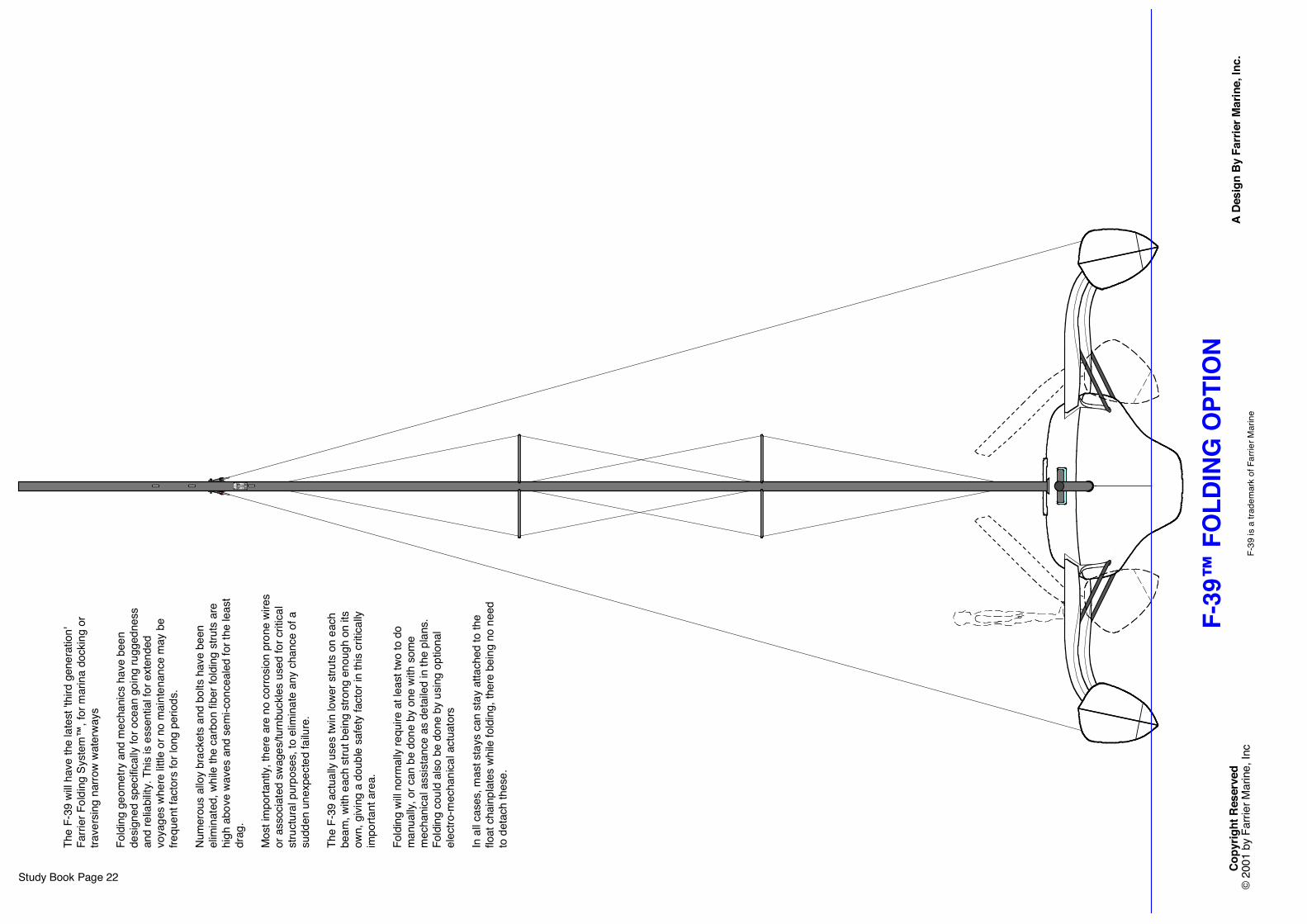
The
F-39
will
have
the
late
st 't
hird
gen
erat
ion'
Fa
rrier
Fol
ding
Sys
tem
™, f
or m
arin
a do
ckin
g or
tra
vers
ing
narro
w wa
terw
ays
Fold
ing
geom
etry
and
mec
hani
cs h
ave
been
de
signe
d sp
ecific
ally
for o
cean
goi
ng ru
gged
ness
an
d re
liabi
lity.
Thi
s is
esse
ntia
l for
ext
ende
d vo
yage
s wh
ere
little
or n
o m
aint
enan
ce m
ay b
e fre
quen
t fac
tors
for l
ong
perio
ds.
Num
erou
s al
loy
brac
kets
and
bol
ts h
ave
been
el
imin
ated
, whi
le th
e ca
rbon
fibe
r fol
ding
stru
ts a
re
high
abo
ve w
aves
and
sem
i-con
ceal
ed fo
r the
leas
t dr
ag.
Mos
t im
porta
ntly,
ther
e ar
e no
cor
rosio
n pr
one
wire
s or
ass
ocia
ted
swag
es/tu
rnbu
ckle
s us
ed fo
r crit
ical
stru
ctur
al p
urpo
ses,
to e
limin
ate
any
chan
ce o
f a
sudd
en u
nexp
ecte
d fa
ilure
.
The
F-39
act
ually
use
s tw
in lo
wer s
truts
on
each
be
am, w
ith e
ach
stru
t bei
ng s
trong
eno
ugh
on it
s ow
n, g
iving
a d
oubl
e sa
fety
fact
or in
this
critic
ally
impo
rtant
are
a.
Fold
ing
will n
orm
ally
requ
ire a
t lea
st tw
o to
do
man
ually
, or c
an b
e do
ne b
y on
e wi
th s
ome
mec
hani
cal a
ssist
ance
as
deta
iled
in th
e pl
ans.
Fo
ldin
g co
uld
also
be
done
by
usin
g op
tiona
l el
ectro
-mec
hani
cal a
ctua
tors
In a
ll cas
es, m
ast s
tays
can
sta
y at
tach
ed to
the
float
cha
inpl
ates
whi
le fo
ldin
g, th
ere
bein
g no
nee
d to
det
ach
thes
e.
A De
sign
By
Farr
ier M
arin
e, In
c.F-
39™
FO
LDIN
G O
PTIO
NCo
pyrig
ht R
eser
ved
© 2
001
by F
arrie
r Mar
ine,
Inc
F-39
is a
trad
emar
k of
Far
rier M
arin
e
Study Book Page 22
®
41
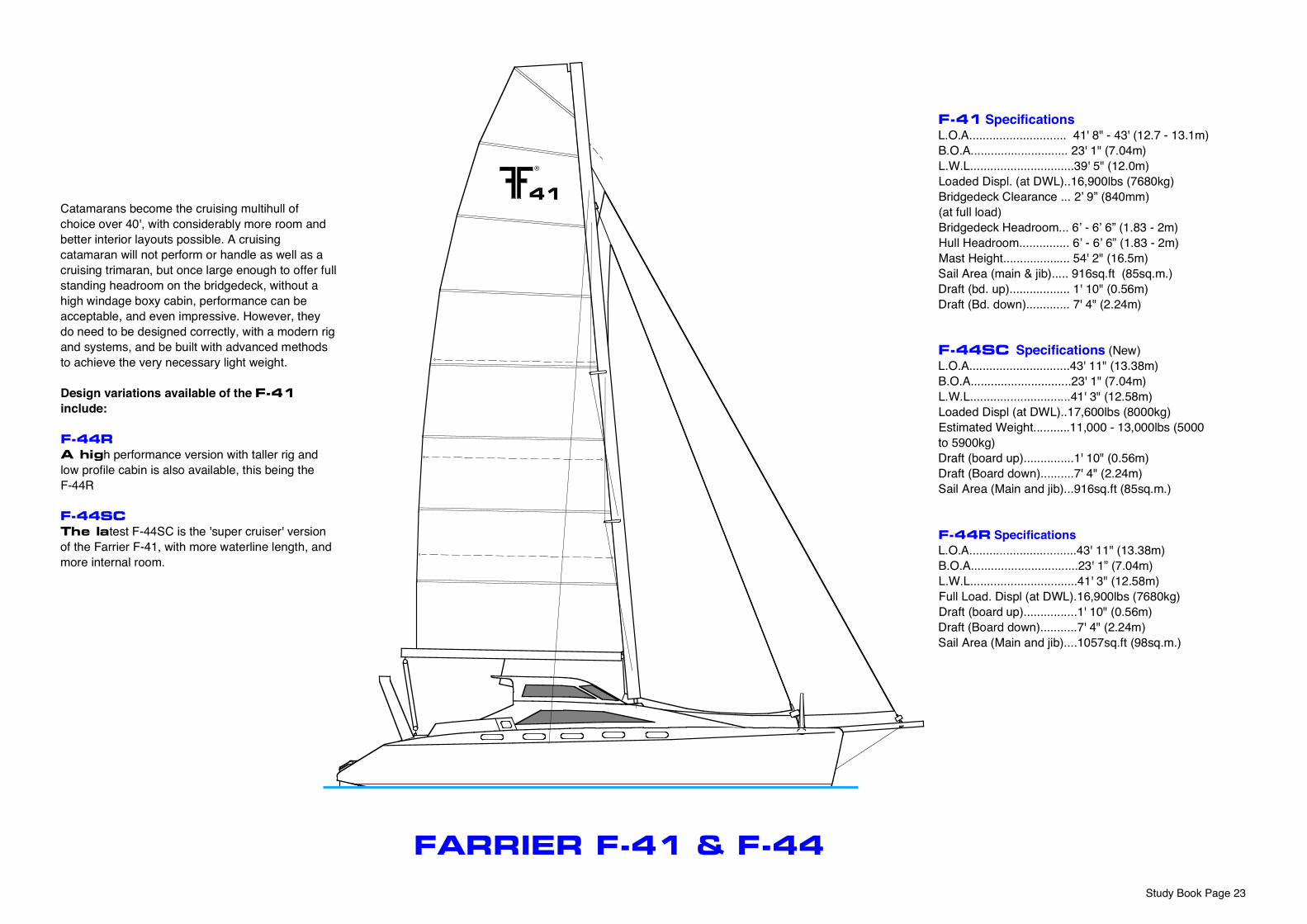
FARRIER F-41 & F-44
Study Book Page 23
F-41 SpecificationsL.O.A............................. 41' 8" - 43' (12.7 - 13.1m)B.O.A............................. 23' 1" (7.04m)L.W.L...............................39' 5" (12.0m)Loaded Displ. (at DWL)..16,900lbs (7680kg)Bridgedeck Clearance ... 2’ 9” (840mm) (at full load) Bridgedeck Headroom... 6’ - 6’ 6” (1.83 - 2m)Hull Headroom............... 6’ - 6’ 6” (1.83 - 2m)Mast Height.................... 54' 2" (16.5m)Sail Area (main & jib)..... 916sq.ft (85sq.m.)Draft (bd. up).................. 1' 10" (0.56m)Draft (Bd. down)............. 7' 4" (2.24m)
F-44SC Specifications (New)L.O.A..............................43' 11" (13.38m)B.O.A..............................23' 1" (7.04m)L.W.L..............................41' 3" (12.58m)Loaded Displ (at DWL)..17,600lbs (8000kg)Estimated Weight...........11,000 - 13,000lbs (5000 to 5900kg)Draft (board up)...............1' 10" (0.56m)Draft (Board down)..........7' 4" (2.24m)Sail Area (Main and jib)...916sq.ft (85sq.m.)
F-44R SpecificationsL.O.A................................43' 11" (13.38m)B.O.A................................23' 1” (7.04m)L.W.L................................41' 3" (12.58m)Full Load. Displ (at DWL).16,900lbs (7680kg)Draft (board up)................1' 10" (0.56m)Draft (Board down)...........7' 4" (2.24m)Sail Area (Main and jib)....1057sq.ft (98sq.m.)
Catamarans become the cruising multihull of choice over 40', with considerably more room and better interior layouts possible. A cruising catamaran will not perform or handle as well as a cruising trimaran, but once large enough to offer full standing headroom on the bridgedeck, without a high windage boxy cabin, performance can be acceptable, and even impressive. However, they do need to be designed correctly, with a modern rig and systems, and be built with advanced methods to achieve the very necessary light weight.
Design variations available of the F-41 include:
F-44R
A high performance version with taller rig and low profile cabin is also available, this being the F-44R
F-44SC
The latest F-44SC is the 'super cruiser' version of the Farrier F-41, with more waterline length, and more internal room.
F-41
INTE
RIO
R O
PTIO
NSA
Desi
gn B
y Fa
rrie
r Mar
ine,
Inc.
Cop
yrig
ht R
eser
ved
© 2
000
by F
arrie
r Mar
ine,
Inc.
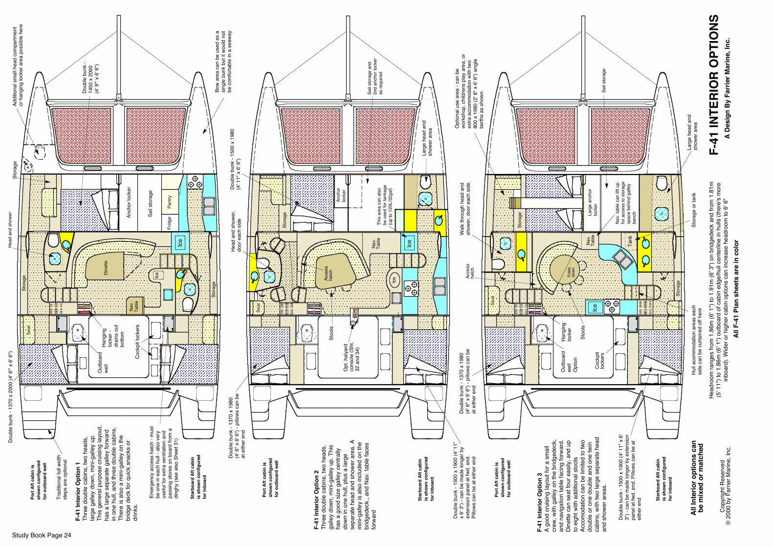
F-41
Inte
rior O
ptio
n 1
Thre
e do
uble
cab
ins,
two
head
s,
larg
e ga
lley
down
, min
i-gal
ley
up.
This
gene
ral p
urpo
se c
ruisi
ng la
yout
, ha
s a
larg
e se
para
te g
alle
y fo
rwar
d in
one
hul
l, an
d th
ree
doub
le c
abin
s.
Ther
e is
also
a m
ini-g
alle
y on
the
brid
ge d
eck
for q
uick
sna
cks
or
drin
ks.
F-41
Inte
rior O
ptio
n 2
Thre
e do
uble
cab
ins,
two
head
s,
galle
y do
wn, m
ini-g
alle
y up
. Thi
s ha
s a
good
siz
e ga
lley
cent
rally
do
wn in
one
hul
l, pl
us a
larg
e se
para
te h
ead
and
show
er a
rea.
A
min
i-gal
ley
is a
lso
incl
uded
on
the
brid
gede
ck.,
and
Nav
. tab
le fa
ces
forw
ard
Head
room
rang
es fr
om 1
.86m
(6' 1
") to
1.9
1m (6
' 3")
on b
ridge
deck
and
from
1.8
1m(5
' 11"
) to
1.86
m (6
' 1")
outb
oard
of c
abin
edg
e/hu
ll cen
terli
ne in
hul
ls (t
here
's m
ore
inbo
ard)
. Wid
er o
r hig
her c
abin
opt
ions
can
incr
ease
hea
droo
m to
6' 6
"
Head
and
sho
wer
Ice
Anch
or lo
cker
Seat
Ice
Nav.
Tabl
e
Frid
ge
Sail s
tora
ge
Stor
age
Pant
ry
Stor
age
Stor
age
Out
boar
d we
ll
Bow
area
can
be
used
as
a sin
gle
bunk
but
it w
ould
not
be
com
forta
ble
in a
sea
way
Doub
le b
unk
- 137
0 x
2000
(4' 6
"' x
6' 6
")
Doub
le b
unk
- 14
50 x
200
0 (4
' 9"'
x 6'
6")
Dine
tteHa
ngin
g lo
cker
- dr
ains
out
bo
ttom
Cock
pit l
ocke
rs
Port
Aft
cabi
n is
sh
own
conf
igur
ed
for o
utbo
ard
wel
l
Emer
genc
y ac
cess
hat
ch -
mus
t be
one
in e
ach
hull -
als
o ve
ry
usef
ul fo
r ext
ra v
entil
atio
n an
d pa
ssin
g st
ores
on
boar
d fro
m a
di
nghy
(see
also
She
et 3
1)
Star
boar
d Af
t cab
in
is s
how
n co
nfig
ured
fo
r inb
oard
Head
and
sho
wer,
door
eac
h si
de
Ice
Anch
or
lock
er
Dine
tte
Sail s
tora
ge a
nd
2nd
anch
or lo
cker
as
requ
ired
Port
Aft
cabi
n is
sh
own
conf
igur
ed
for o
utbo
ard
wel
l
Star
boar
d Af
t cab
in
is s
how
n co
nfig
ured
fo
r inb
oard
Stor
age
Ice
Doub
le b
unk
- 137
0 x
1980
(4
' 6" x
6' 6
") - p
illows
can
be
at e
ither
end
Doub
le b
unk
- 150
0 x
1900
(4' 1
1"
x 6'
3")
- can
be
mad
e lo
nger
by
exte
nsio
n pa
nel a
t fwd
. end
. Pi
llows
can
be
at e
ither
end
Seat
Acce
ss
hatc
h
Doub
le b
unk
- 150
0 x
1980
(4
' 11"
x 6
' 6")
Stoo
ls
Nav.
Tabl
eTh
is ar
ea c
an a
lso
be u
sed
for t
anka
ge
(up
to 1
20L/
32ga
l)
Larg
e he
ad a
nd
show
er a
rea
Opt
. hal
yard
co
nsol
e (S
ht.
32 a
nd 3
4)
All I
nter
ior o
ptio
ns c
anbe
mix
ed o
r mat
ched
Wal
k th
roug
h he
ad a
nd
show
er, d
oor e
ach
side
.
Larg
e an
chor
lo
cker
Dine
tte
Sail s
tora
ge
Port
Aft
cabi
n is
sh
own
conf
igur
ed
for o
utbo
ard
wel
l
Star
boar
d Af
t cab
in
is s
how
n co
nfig
ured
fo
r inb
oard
Stor
age
Stor
age
Out
boar
d we
ll O
ptio
n
Doub
le b
unk
- 137
0 x
1980
(4
' 6" x
6' 6
") - p
illows
can
be
at e
ither
end
Doub
le b
unk
- 150
0 x
1900
(4' 1
1" x
6'
3") -
can
be
mad
e lo
nger
by
exte
nsio
n pa
nel a
t fwd
. end
. Pillo
ws c
an b
e at
ei
ther
end
Cock
pit
lock
ers
Hull a
com
mod
atio
n ar
eas
each
sid
e ca
n be
cur
tain
ed o
ff he
re
Seat
Acce
ss
hatc
h
Opt
iona
l use
are
a - c
an b
e wo
rksh
op, c
hild
rens
pla
y ar
ea, o
r ex
tra a
ccom
mod
atio
n w
ith tw
o 80
0 x
1980
(2' 8
" x 6
' 6")
singl
e be
rths
as s
how
n.
Nav.
Tabl
e
Nav.
tabl
e ca
n lif
t up
for a
cces
s to
sto
rage
sp
ace
behi
nd g
alle
y be
nch
Larg
e he
ad a
nd
show
er a
rea
Ice
Tank
Hang
ing
lock
er
Stoo
ls
Fold
s do
wn
Stor
age
or ta
nk
F-41
Inte
rior O
ptio
n 3
A go
od c
ruis
ing
layo
ut fo
r a s
mal
l cr
ew, w
ith g
alle
y on
the
brid
gede
ck,
and
navig
atio
n ta
ble
faci
ng fo
rwar
d.
Dine
tte c
an s
eat f
our e
asily
, and
up
to e
ight
with
add
itiona
l sto
ols
Acco
mod
atio
n ca
n be
limite
d to
two
doub
le o
r one
dou
ble
and
one
twin
ca
bins
, with
two
larg
e se
para
te h
ead
and
show
er a
reas
.
Trad
itiona
l ful
l wid
th
step
s ar
e op
tiona
l
Addi
tiona
l sm
all h
ead
com
partm
ent
or h
angi
ng lo
cker
are
a po
ssib
le h
ere
Study Book Page 24
All F
-41
Plan
she
ets
are
in c
olor
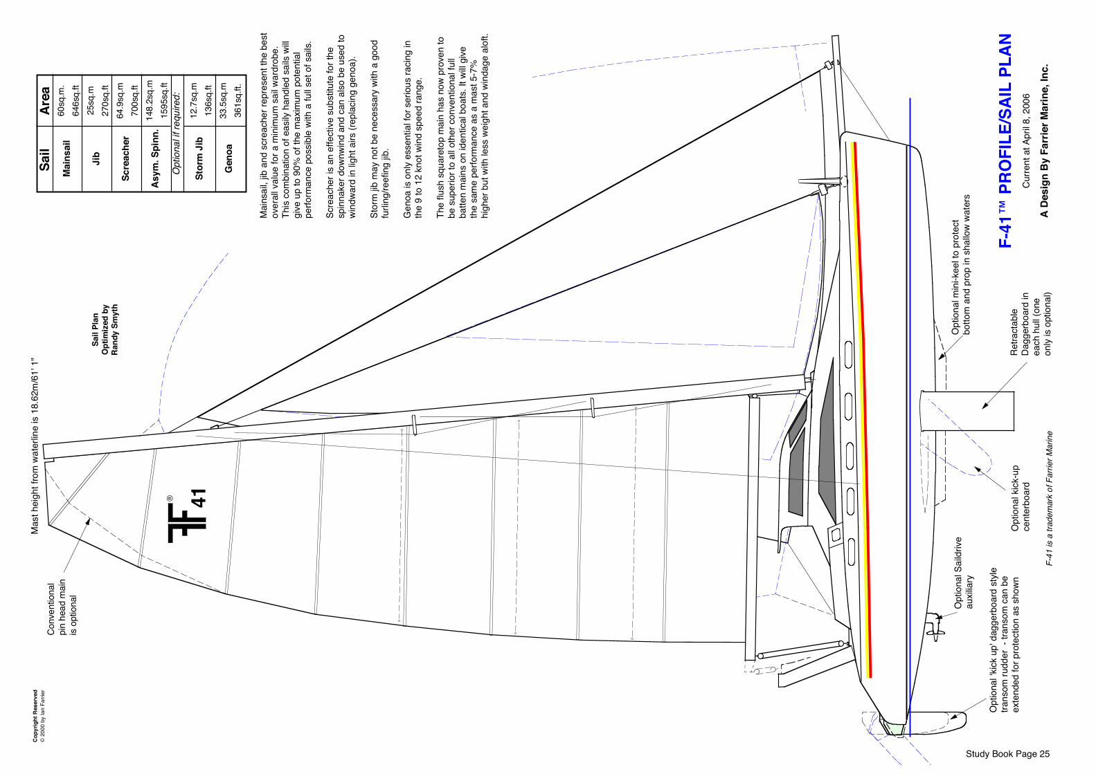
F-41
™ P
ROFI
LE/S
AIL
PLAN
Curre
nt a
t Apr
il 8, 2
006
A De
sign
By
Farr
ier M
arin
e, In
c.
Cop
yrig
ht R
eser
ved
© 2
000
by Ia
n Fa
rrier
Sail
Plan
Opt
imiz
ed b
yRa
ndy
Smyt
h
Mai
nsai
l
Jib
Scre
ache
r
Asym
. Spi
nn.
Stor
m J
ib
Gen
oa
® 41
Opt
iona
l 'kick
up'
dag
gerb
oard
sty
le
trans
om ru
dder
- tr
anso
m c
an b
e ex
tend
ed fo
r pro
tect
ion
as s
hown
Opt
iona
l Sai
ldriv
e au
xilia
ryO
ptio
nal m
ini-k
eel t
o pr
otec
t bo
ttom
and
pro
p in
sha
llow
wate
rs
Conv
entio
nal
pin
head
mai
n is
optio
nal
Mas
t hei
ght f
rom
wat
erlin
e is
18.
62m
/61'
1"
Sail
60sq
.m.
646s
q.ft
25sq
.m27
0sq.
ft64
.9sq
.m70
0sq.
ft14
8.2s
q.m
1595
sq.ft
12.7
sq.m
136s
q.ft
33.5
sq.m
361s
q.ft.
Opt
iona
l if re
quire
d:
Retra
ctab
le
Dagg
erbo
ard
in
each
hul
l (on
e on
ly is
optio
nal)
F-41
is a
trad
emar
k of
Far
rier M
arin
e
Mai
nsai
l, jib
and
scr
each
er re
pres
ent t
he b
est
over
all v
alue
for a
min
imum
sai
l war
drob
e.
This
com
bina
tion
of e
asily
han
dled
sai
ls wi
ll gi
ve u
p to
90%
of t
he m
axim
um p
oten
tial
perfo
rman
ce p
ossib
le w
ith a
full s
et o
f sai
ls.
Scre
ache
r is
an e
ffect
ive s
ubst
itute
for t
he
spin
nake
r dow
nwin
d an
d ca
n al
so b
e us
ed to
wi
ndwa
rd in
light
airs
(rep
lacin
g ge
noa)
.
Stor
m jib
may
not
be
nece
ssar
y wi
th a
goo
d fu
rling
/reef
ing
jib.
Gen
oa is
onl
y es
sent
ial f
or s
erio
us ra
cing
in
the
9 to
12
knot
win
d sp
eed
rang
e.
The
flush
squ
aret
op m
ain
has
now
prov
en to
be
sup
erio
r to
all o
ther
con
vent
iona
l ful
l ba
tten
mai
ns o
n id
entic
al b
oats
. It w
ill gi
ve
the
sam
e pe
rform
ance
as
a m
ast 5
-7%
hi
gher
but
with
less
wei
ght a
nd w
inda
ge a
loft.
Area
Opt
iona
l kic
k-up
ce
nter
boar
d
Study Book Page 25
Copy
right
Res
erve
d ©
200
1 by
Far
rier M
arin
e, In
c.Sc
ale
1 : 6
0
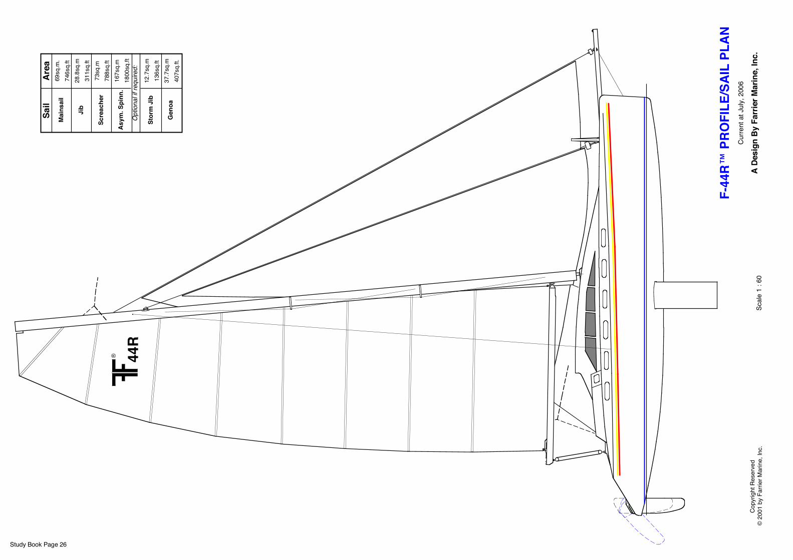
® 44R
Mai
nsai
l
Jib
Scre
ache
r
Asym
. Spi
nn.
Stor
m J
ib
Gen
oa
Sail
69sq
.m.
746s
q.ft
28.8
sq.m
311s
q.ft
73sq
.m78
8sq.
ft16
7sq.
m18
00sq
.ft
12.7
sq.m
136s
q.ft
37.7
sq.m
407s
q.ft.
Opt
iona
l if re
quire
d:
Area
Study Book Page 26
F-44
R™ P
ROFI
LE/S
AIL
PLAN
Curre
nt a
t Jul
y, 2
006
A De
sign
By
Farr
ier M
arin
e, In
c.
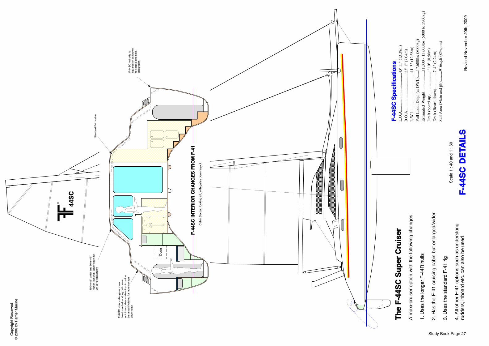
F-44
SC D
ETAI
LS
Copy
right
Res
erve
d©
200
6 by
Far
rier M
arin
e
Scal
e 1
: 40
and
1 : 6
0
Revis
ed N
ovem
ber 2
0th,
200
9
The
F-44
SC S
uper
Cru
iser
A m
axi-c
ruise
r opt
ion
with
the
follo
wing
cha
nges
:
1. U
ses
the
long
er F
-44R
hul
ls
2. H
as th
e F-
41 c
ruisi
ng c
abin
but
enl
arge
d/wi
der
3. U
ses
the
stan
dard
F-4
1 rig
4. A
ll oth
er F
-41
optio
ns s
uch
as u
nder
slung
ru
dder
s, in
boar
d et
c. c
an a
lso b
e us
ed
® 44SC
Study Book Page 27
F-44
SC S
peci
ficat
ions
L.O
.A...
......
......
......
......
......
....4
3' 1
1" (1
3.38
m)
B.O
.A...
......
......
......
......
......
....2
3' 1
" (7.
04m
)L.
W.L
......
......
......
......
......
......
.41'
3" (
12.5
8m)
Full
Load
. Disp
l (at
DW
L)...
...17
,600
lbs (
8000
kg)
Estim
ated
Wei
ght..
......
......
......
11,0
00 -
13,0
00lb
s (50
00 to
590
0kg)
Dra
ft (b
oard
up)
......
......
......
....1
' 10"
(0.5
6m)
Dra
ft (B
oard
dow
n)...
......
......
.7' 4
" (2.
24m
)Sa
il A
rea
(Mai
n an
d jib
).....
.....9
16sq
.ft (8
5sq.
m.)
Cabi
n Se
ctio
n lo
okin
g af
t, wi
th g
alle
y do
wn la
yout
F-44
SC w
ider
cab
in g
ives
mor
e he
adro
om b
elow
alo
ng h
ull c
ente
r, wh
ich a
lso a
llows
cab
in fl
oor i
n hu
ll to
be ra
ised
if wi
shed
for m
ore
stor
age
unde
rnea
th
150m
m/6
" wid
er a
nd 8
0mm
/3"
high
er (o
ptio
nal)
uppe
r cab
in fo
r 2m
(6' 6
") he
adro
omSt
anda
rd F
-41
cabi
n
F-44
SC h
ull s
ide
is sq
uare
d of
f as
show
n to
kee
p a
safe
sid
e de
ck w
idth
Ove
n
F-44
SC IN
TERI
OR
CHAN
GES
FRO
M F
-41
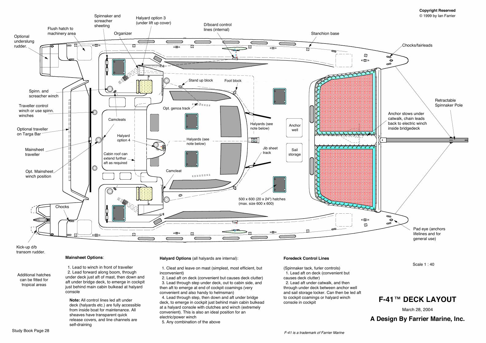
Copyright Reserved © 1999 by Ian Farrier
F-41™ DECK LAYOUTMarch 28, 2004
A Design By Farrier Marine, Inc.
Additional hatchescan be fitted fortropical areas
Halyard Options (all halyards are internal):
1. Cleat and leave on mast (simplest, most efficient, but inconvenient) 2. Lead aft on deck (convenient but causes deck clutter) 3. Lead through step under deck, out to cabin side, and then aft to emerge at end of cockpit coamings (very convenient and also handy to helmsman) 4. Lead through step, then down and aft under bridge deck, to emerge in cockpit just behind main cabin bulkead at a halyard console with clutches and winch (extremely convenient). This is also an ideal position for an electric/power winch 5. Any combination of the above
Mainsheet Options:
1. Lead to winch in front of traveller 2. Lead forward along boom, through under deck just aft of mast, then down and aft under bridge deck, to emerge in cockpit just behind main cabin bulkead at halyard console
Foredeck Control Lines
(Spinnaker tack, furler controls) 1. Lead aft on deck (convenient but causes deck clutter) 2. Lead aft under catwalk, and then through under deck between anchor well and sail storage locker. Can then be led aft to cockpit coamings or halyard winch console in cockpit Note: All control lines led aft under
deck (halyards etc.) are fully accessible from inside boat for maintenance. All sheaves have transparent quick release covers, and line channels are self-draining
Scale 1 : 40
F-41 is a trademark of Farrier Marine
Anchor stows under catwalk, chain leads back to electric winch inside bridgedeck
Anchorwell
Sailstorage
Stanchion base
Chocks/fairleads
Pad eye (anchors lifelines and for general use)
Retractable Spinnaker Pole
Jib sheet track
Halyards (see note below)
Flush hatch to machinery area
Halyard option 3(under lift up cover)
Spinnaker and screacher sheeting D/board control
lines (internal)Organizer
Opt. genoa track
Stand up block Foot block
Camcleat
500 x 600 (20 x 24") hatches (max. size 600 x 600)
Halyards (see note below)
Halyard option 4
Opt. Mainsheet winch position
Traveller control winch or use spinn. winches
Optional traveller on Targa Bar
Spinn. and screacher winch
Camcleats
Mainsheet traveller Cabin roof can
extend further aft as required
Kick-up d/b transom rudder.
Chocks
Optional underslung rudder.
Study Book Page 28
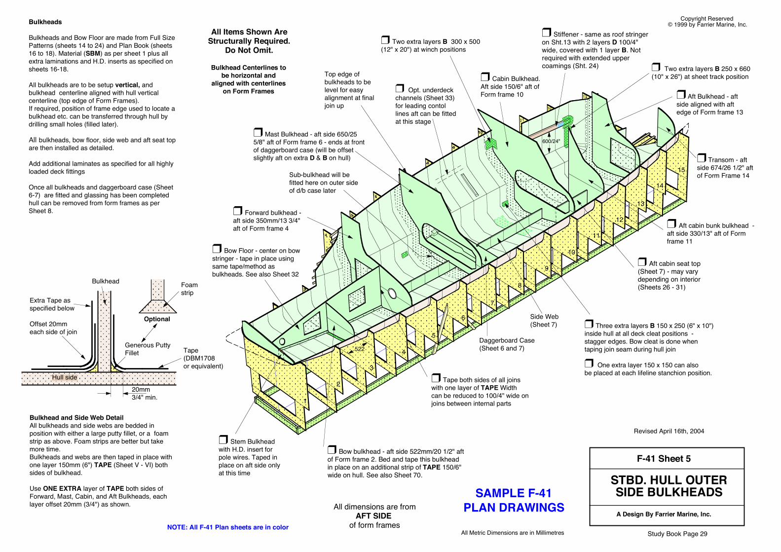
F-41 Sheet 5
STBD. HULL OUTERSIDE BULKHEADSA Design By Farrier Marine, Inc.
All Metric Dimensions are in Millimetres
Copyright Reserved © 1999 by Farrier Marine, Inc.Bulkheads
Bulkheads and Bow Floor are made from Full Size Patterns (sheets 14 to 24) and Plan Book (sheets 16 to 18). Material (SBM) as per sheet 1 plus all extra laminations and H.D. inserts as specified on sheets 16-18.
All bulkheads are to be setup vertical, and bulkhead centerline aligned with hull vertical centerline (top edge of Form Frames). If required, position of frame edge used to locate a bulkhead etc. can be transferred through hull by drilling small holes (filled later).
All bulkheads, bow floor, side web and aft seat top are then installed as detailed.
Add additional laminates as specified for all highly loaded deck fittings
Once all bulkheads and daggerboard case (Sheet 6-7) are fitted and glassing has been completed hull can be removed from form frames as per Sheet 8.
All dimensions are fromAFT SIDE
of form frames
1
2
3
4
6
7
8
9
10
11
12
13
14
15
5
10
11
12
4
6
5
3
9
7
8
❒ Stem Bulkhead with H.D. insert for pole wires. Taped in place on aft side only at this time
❒ Bow Floor - center on bow stringer - tape in place using same tape/method as bulkheads. See also Sheet 32
❒ Bow bulkhead - aft side 522mm/20 1/2" aft of Form frame 2. Bed and tape this bulkhead in place on an additional strip of TAPE 150/6" wide on hull. See also Sheet 70.
❒ Forward bulkhead - aft side 350mm/13 3/4" aft of Form frame 4
Top edge of bulkheads to be level for easy alignment at final join up
Daggerboard Case (Sheet 6 and 7)
Bulkhead and Side Web DetailAll bulkheads and side webs are bedded in position with either a large putty fillet, or a foam strip as above. Foam strips are better but take more time. Bulkheads and webs are then taped in place with one layer 150mm (6") TAPE (Sheet V - VI) both sides of bulkhead.
Use ONE EXTRA layer of TAPE both sides of Forward, Mast, Cabin, and Aft Bulkheads, each layer offset 20mm (3/4") as shown.
Tape(DBM1708 or equivalent)
Generous Putty Fillet
Bulkhead
20mm3/4" min.
❒ Transom - aft side 674/26 1/2" aft of Form Frame 14
❒ Three extra layers B 150 x 250 (6" x 10") inside hull at all deck cleat positions - stagger edges. Bow cleat is done when taping join seam during hull join
❒ One extra layer 150 x 150 can also be placed at each lifeline stanchion position.Hull side
❒ Two extra layers B 300 x 500 (12" x 20") at winch positions
❒ Mast Bulkhead - aft side 650/25 5/8" aft of Form frame 6 - ends at front of daggerboard case (will be offset slightly aft on extra D & B on hull)
❒ Cabin Bulkhead. Aft side 150/6" aft of Form frame 10 ❒ Aft Bulkhead - aft
side aligned with aft edge of Form frame 13
❒ Aft cabin bunk bulkhead - aft side 330/13" aft of Form frame 11
522
❒ Tape both sides of all joins with one layer of TAPE Width can be reduced to 100/4" wide on joins between internal parts
❒ Two extra layers B 250 x 660 (10" x 26") at sheet track position
Optional
Sub-bulkhead will be fitted here on outer side of d/b case later
All Items Shown AreStructurally Required.
Do Not Omit.
Side Web (Sheet 7)
Extra Tape as specified below
Offset 20mm each side of join
❒ Aft cabin seat top (Sheet 7) - may vary depending on interior (Sheets 26 - 31)Foam
strip
Bulkhead Centerlines tobe horizontal and
aligned with centerlineson Form Frames
13❒ Opt. underdeck channels (Sheet 33) for leading contol lines aft can be fitted at this stage
600/24"
❒ Stiffener - same as roof stringer on Sht.13 with 2 layers D 100/4" wide, covered with 1 layer B. Not required with extended upper coamings (Sht. 24)
Study Book Page 29NOTE: All F-41 Plan sheets are in color
SAMPLE F-41PLAN DRAWINGS
Revised April 16th, 2004
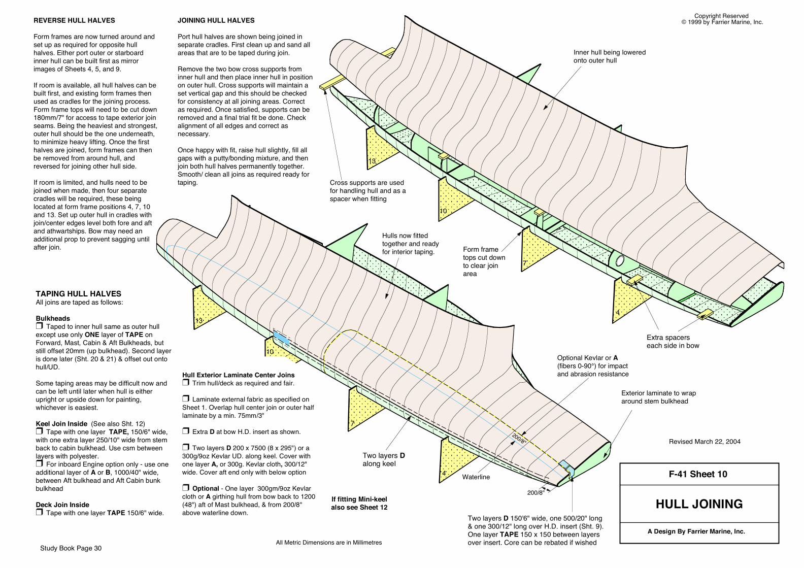
F-41 Sheet 10
HULL JOINING
A Design By Farrier Marine, Inc.All Metric Dimensions are in Millimetres
Copyright Reserved © 1999 by Farrier Marine, Inc.
4
7
10
13
4
7
10
13
TAPING HULL HALVES All joins are taped as follows:
Bulkheads ❒ Taped to inner hull same as outer hull except use only ONE layer of TAPE on Forward, Mast, Cabin & Aft Bulkheads, but still offset 20mm (up bulkhead). Second layer is done later (Sht. 20 & 21) & offset out onto hull/UD.
Some taping areas may be difficult now and can be left until later when hull is either upright or upside down for painting, whichever is easiest.
Keel Join Inside (See also Sht. 12)❒ Tape with one layer TAPE, 150/6" wide, with one extra layer 250/10" wide from stem back to cabin bulkhead. Use csm between layers with polyester.❒ For inboard Engine option only - use one additional layer of A or B, 1000/40" wide, between Aft bulkhead and Aft Cabin bunk bulkhead
Deck Join Inside ❒ Tape with one layer TAPE 150/6" wide.
REVERSE HULL HALVES
Form frames are now turned around and set up as required for opposite hull halves. Either port outer or starboard inner hull can be built first as mirror images of Sheets 4, 5, and 9.
If room is available, all hull halves can be built first, and existing form frames then used as cradles for the joining process. Form frame tops will need to be cut down 180mm/7" for access to tape exterior join seams. Being the heaviest and strongest, outer hull should be the one underneath, to minimize heavy lifting. Once the first halves are joined, form frames can then be removed from around hull, and reversed for joining other hull side.
If room is limited, and hulls need to be joined when made, then four separate cradles will be required, these being located at form frame positions 4, 7, 10 and 13. Set up outer hull in cradles with join/center edges level both fore and aft and athwartships. Bow may need an additional prop to prevent sagging until after join.
Hulls now fitted together and ready for interior taping.
JOINING HULL HALVES
Port hull halves are shown being joined in separate cradles. First clean up and sand all areas that are to be taped during join.
Remove the two bow cross supports from inner hull and then place inner hull in position on outer hull. Cross supports will maintain a set vertical gap and this should be checked for consistency at all joining areas. Correct as required. Once satisfied, supports can be removed and a final trial fit be done. Check alignment of all edges and correct as necessary.
Once happy with fit, raise hull slightly, fill all gaps with a putty/bonding mixture, and then join both hull halves permanently together. Smooth/ clean all joins as required ready for taping.
Hull Exterior Laminate Center Joins ❒ Trim hull/deck as required and fair.
❒ Laminate external fabric as specified on Sheet 1. Overlap hull center join or outer half laminate by a min. 75mm/3"
❒ Extra D at bow H.D. insert as shown.
❒ Two layers D 200 x 7500 (8 x 295") or a 300g/9oz Kevlar UD. along keel. Cover with one layer A, or 300g. Kevlar cloth, 300/12" wide. Cover aft end only with below option
❒ Optional - One layer 300gm/9oz Kevlar cloth or A girthing hull from bow back to 1200 (48") aft of Mast bulkhead, & from 200/8" above waterline down.
Exterior laminate to wrap around stem bulkhead
Extra spacers each side in bow
Inner hull being lowered onto outer hull
Cross supports are used for handling hull and as a spacer when fitting
200/8"
Two layers D along keel
Waterline
Optional Kevlar or A(fibers 0-90°) for impact and abrasion resistance
Form frame tops cut down to clear join area
200/8"
Two layers D 150'6" wide, one 500/20" long & one 300/12" long over H.D. insert (Sht. 9). One layer TAPE 150 x 150 between layers over insert. Core can be rebated if wished
If fitting Mini-keelalso see Sheet 12
Study Book Page 30
Revised March 22, 2004
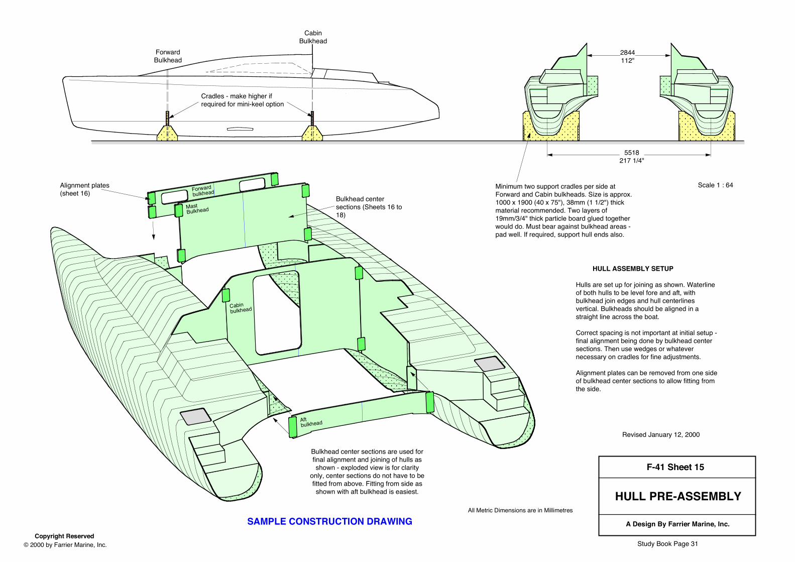
F-41 Sheet 15
HULL PRE-ASSEMBLY
A Design By Farrier Marine, Inc.Copyright Reserved
© 2000 by Farrier Marine, Inc.
All Metric Dimensions are in Millimetres
Forward bulkhead
Bulkhead center sections (Sheets 16 to 18)
Cabin bulkhead
Cabin bulkhead
Revised January 12, 2000
5518217 1/4"
2844112"
HULL ASSEMBLY SETUP
Hulls are set up for joining as shown. Waterline of both hulls to be level fore and aft, with bulkhead join edges and hull centerlines vertical. Bulkheads should be aligned in a straight line across the boat.
Correct spacing is not important at initial setup - final alignment being done by bulkhead center sections. Then use wedges or whatever necessary on cradles for fine adjustments.
Alignment plates can be removed from one side of bulkhead center sections to allow fitting from the side.
Minimum two support cradles per side at Forward and Cabin bulkheads. Size is approx. 1000 x 1900 (40 x 75"), 38mm (1 1/2") thick material recommended. Two layers of 19mm/3/4" thick particle board glued together would do. Must bear against bulkhead areas - pad well. If required, support hull ends also.
Cradles - make higher if required for mini-keel option
Bulkhead center sections are used forfinal alignment and joining of hulls asshown - exploded view is for clarity
only, center sections do not have to befitted from above. Fitting from side asshown with aft bulkhead is easiest.
ForwardBulkhead
CabinBulkhead
Alignment plates (sheet 16)
Mast Bulkhead
Aft bulkhead
Scale 1 : 64
SAMPLE CONSTRUCTION DRAWING
Study Book Page 31
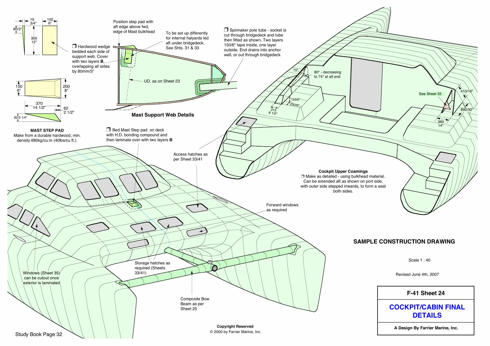
F-41 Sheet 24
COCKPIT/CABIN FINALDETAILS
A Design By Farrier Marine, Inc.Copyright Reserved © 2000 by Farrier Marine, Inc.
Revised June 4th, 2007
Scale 1 : 40
❒ Bed Mast Step pad on deck with H.D. bonding compound and then laminate over with two layers B .
Forward windows as required
Access hatches as per Sheet 33/41
Storage hatches as required (Sheets 33/41)Windows (Sheet 35)
can be cutout onceexterior is laminated
Composite Bow Beam as per Sheet 25
Cockpit Upper Coamings❒ Make as detailed - using bulkhead material.Can be extended aft as shown on port side,
with outer side stepped inwards, to form a seatboth sides.
Cabin bulkhead
890/35"
410/16"See Sheet 33
2158 1/2"
36014"
80° - decreasing to 74° at aft end
73°
230/9"155/6"
Mast Support Web Details
SAMPLE CONSTRUCTION DRAWING
Study Book Page 32
❒ Hardwood wedge bedded each side of support web. Cover with two layers B, overlapping all sides by 80mm/3"
Position step pad with aft edge above fwd. edge of Mast bulkhead To be set up differently
for internal halyards led aft under bridgedeck. See Shts. 31 & 33
UD. as on Sheet 23
❒ Spinnaker pole tube - socket is cut through bridgedeck and tube then fitted as shown, Two layers 150/6" tape inside, one layer outside. End drains into anchor well, or out through bridgedeck
37014 1/2"
82/3 1/4"
622 1/2"
1506"
2008"
MAST STEP PADMake from a durable hardwood, min.
density 680kg/cu.m (40lbs/cu ft.).
30012"
1506"
193/4"
80/3"
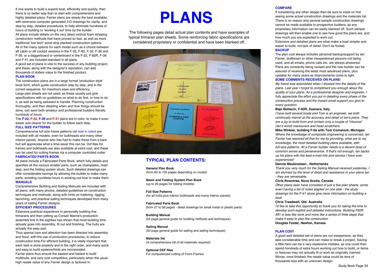
Study Book Page 33
PLANSThe following pages detail actual plan contents and have examples oftypical trimaran plan sheets. Some reinforcing fabric specifications are
considered proprietary or confidential and have been blanked off.
If one wants to build a superb boat, efficiently and quickly, then there is no better way than to start with comprehensive and highly detailed plans. Farrier plans are simply the best available, with extensive computer generated 3-D drawings for clarity, and step by step, detailed procedures, to help eliminate hundreds of hours of building or 'working it out' time by the builder.All plans include details on the very latest vertical foam stripping construction methods that have proved so fast, as well as more traditional 'low tech' wood strip planked construction options.All of the many options for each model such as a choice between aft cabin or aft cockpit versions in the F-22, F-82, F-32, F-36 and F-39, or a daggerboard or centerboard in the F-22, F-82R, F-36 and F-41 are included standard in all plans.A good set of plans is vital to the success of any building project, and these, along with the designer's reputation, can add thousands of dollars value to the finished product.PLAN BOOKThe construction plans are in a large format 'production style' book form, which guide construction step by step, and in the correct sequence, for maximum ease and efficiency.Large plan sheets are not used, as these usually just give specifications with no guidelines on what to do first, or how to do it, as well as being awkward to handle. Planning construction thoroughly, and then detailing when and how things should be done, can save both amateur and professional builders literally hundreds of hours.The F-22, F-32, F-39 and F-41 plans are in color, to make it even easier and clearer for the builder to follow each step.FULL SIZE PATTERNSComprehensive full size frame patterns (all now in color) are included with all models, even for bulkheads and many other interior panels. Anyone who has had to make these from a bare hull will appreciate what a time saver this can be. Dxf files for frames and bulkheads are also available at extra cost, and these can be used for cutting frames via a computer controlled cutter.FABRICATED PARTS BOOKAll plans include a Fabricated Parts Book, which fully details and specifies all the various smaller parts, such as chainplates, mast step, and the folding system struts. Such detailed drawings can offer considerable savings by allowing the builder to make many parts, avoiding countless hours in working out how to make them.MANUALSComprehensive Building and Sailing Manuals are included with all plans, with many photos, detailed guidelines on construction techniques and methods, along with hints on trailering, rigging, launching, and practical sailing techniques developed from many years of sailing Farrier designs.EFFICIENT PROCEDURESExtensive practical experience in personally building five trimarans and then setting up Corsair Marine's production assembly line in the eighties has shown that most building time actually goes into assembly, fit out and finishing. The hulls are actually the easy part. Thus special care and attention has been directed into assembly and fitout, with the use of production procedures, to reduce construction time.For efficient building, it is vitally important that each task is done properly and in the right order, and many quick and easy to build systems/hints are incorporated.Farrier plans thus ensure the easiest and fastest to build multihulls, and very cost competitive, particularly when the usual high resale value of any Farrier design is factored in.
COMPAREIf considering any other design then be sure to insist on first seeing some actual construction drawings and the materials list. There is no reason why several sample construction drawings cannot be made available to prospective builders, as any proprietary information can be easily blanked off. Such sample drawings will then enable one to see how good the plans are, and how much you are expected to work out.Extensive and detailed plans are what make a boat simpler and easier to build, not lack of detail. Don't be fooled.BACKUPThe plan cost always includes personal backup/support by Ian Farrier, draftsmen or other inexperienced persons not being used, and all emails, phone calls etc. are always answered. Plans are constantly being revised and the new builder can be assured of receiving the latest most advanced plans, plus updates for many years as improvements come to light.SOME COMMENTS RECEIVED ON PLANS:My friend was astonished when I showed him the details of the plans. Last year I forgot to compliment you enough about the quality of your plans. As a professional designer and engineer, I fully appreciate the effort you put in detailing every phase of the construction process and the instant email support you give to every question. Bepi Bottacin, F-82R, Soanara, ItalyI have built several boats and Tom is an engineer, we both continually marvel at the accuracy and detail of Ian's plans. They are a joy to build from and contain only a couple of "irksome" (Ian's word) maneuvers and head scratchers.Mike Winkler, building F-9s with Tom Comstock, MichiganWhere the knowledge of composite engineering is concerned, Ian Farrier has resolved all that for me by providing, what are to my knowledge, the most detailed building plans available, with full-size patterns. All a Farrier builder needs is a decent dose of common sense and perseverance. If that's not enough, Ian backs up his plans with the best e-mail info and service I have ever experienced!Dennis Meulensteen , NetherlandsThank you very much for the Sailing Manual received yesterday. I am stunned by the level of detail and assistance in your plans Ian - they are remarkable.Chris Rowntree, Nova Scotia, CanadaOther plans seen have consisted of just a few plan sheets, some even having a list of notes stapled on one side - the study drawings for the F-41 alone give more information on building a boat.Chris Treadwell, Qld. Australia I'd like to take this opportunity to thank you for taking the time to develop such explicit and detailed instructions. Building F82R #91 is less like work and more like a series of finite steps that make it easy to plan the construction Douglas Foster, Newton, Kansas
PLAN COSTA good well detailed set of plans are not inexpensive, as they take considerable time and can make or break a project. Saving a little here can be a very expensive mistake, as one could then spend hundreds of extra hours working out how to build, or items or features may not actually fit or work as originally claimed. Worse, once finished, the resale value could be tens of thousands less with an unknown design.
TYPICAL PLAN CONTENTS:General Plan Book (from 60 to 105 pages depending on model)
Beam and Folding System Plan Book(up to 20 pages for folding models)
Full Size Patterns (for all hulls plus interior bulkheads and many interior panels)
Fabricated Parts Book (from 27 to 58 pages - detail drawings for small metal or plastic parts)
Building Manual(54 page general guide for building methods and techniques)
Sailing Manual(50 page general guide for sailing and sailing techniques)
Materials list(A comprehensive list of all materials required)
Optional DXF filesFor computerized cutting of Form Frames
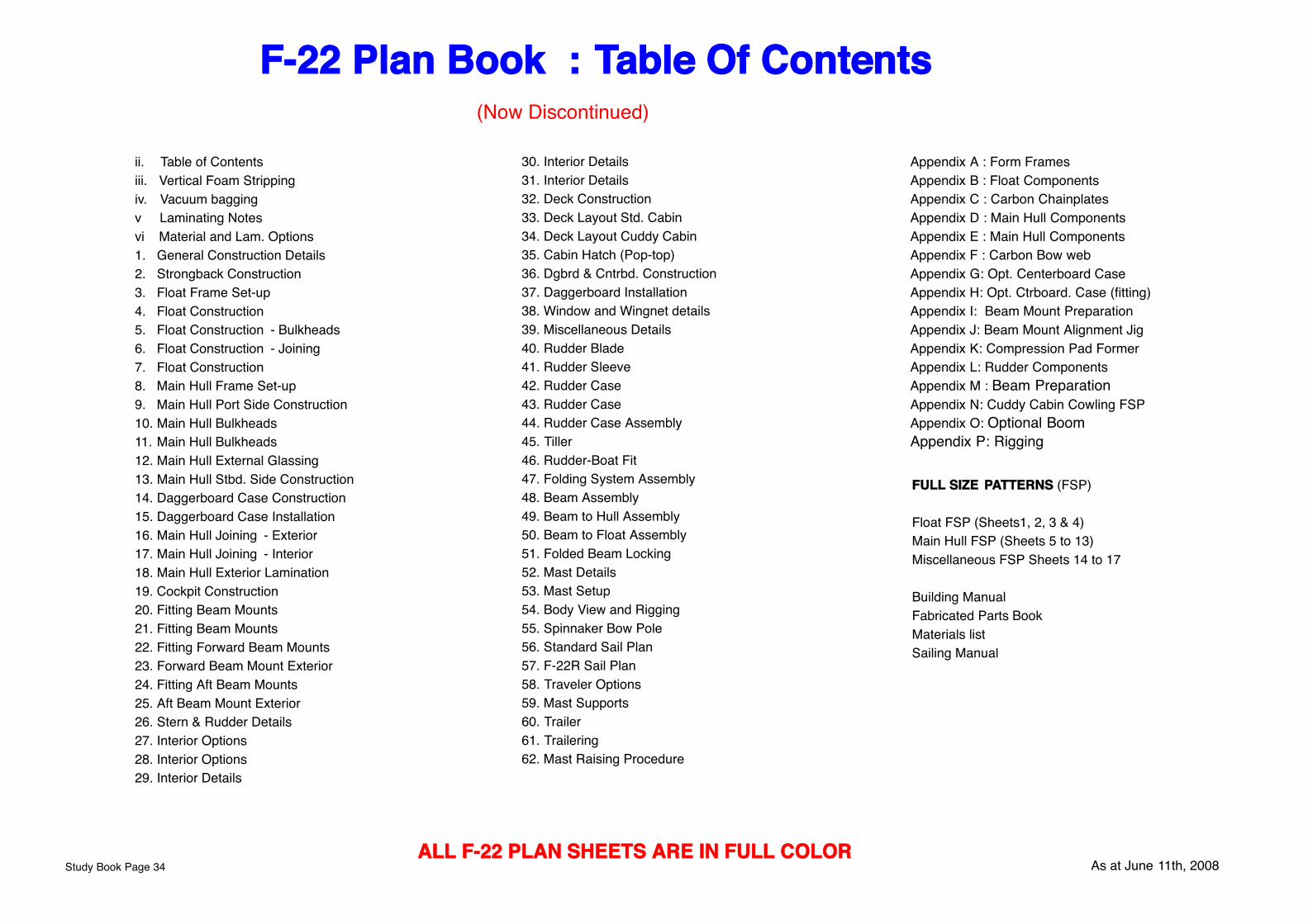
Appendix A : Form FramesAppendix B : Float ComponentsAppendix C : Carbon ChainplatesAppendix D : Main Hull ComponentsAppendix E : Main Hull ComponentsAppendix F : Carbon Bow webAppendix G: Opt. Centerboard CaseAppendix H: Opt. Ctrboard. Case (fitting)Appendix I: Beam Mount PreparationAppendix J: Beam Mount Alignment JigAppendix K: Compression Pad FormerAppendix L: Rudder ComponentsAppendix M : Beam PreparationAppendix N: Cuddy Cabin Cowling FSPAppendix O: Optional BoomAppendix P: Rigging
FULL SIZE PATTERNS (FSP)
Float FSP (Sheets1, 2, 3 & 4)Main Hull FSP (Sheets 5 to 13)Miscellaneous FSP Sheets 14 to 17
Building Manual Fabricated Parts BookMaterials list Sailing Manual
F-22 Plan Book : Table Of Contents
ii. Table of Contentsiii. Vertical Foam Strippingiv. Vacuum baggingv Laminating Notesvi Material and Lam. Options1. General Construction Details2. Strongback Construction3. Float Frame Set-up4. Float Construction5. Float Construction - Bulkheads6. Float Construction - Joining7. Float Construction8. Main Hull Frame Set-up9. Main Hull Port Side Construction10. Main Hull Bulkheads 11. Main Hull Bulkheads 12. Main Hull External Glassing13. Main Hull Stbd. Side Construction 14. Daggerboard Case Construction 15. Daggerboard Case Installation16. Main Hull Joining - Exterior17. Main Hull Joining - Interior18. Main Hull Exterior Lamination19. Cockpit Construction20. Fitting Beam Mounts21. Fitting Beam Mounts22. Fitting Forward Beam Mounts23. Forward Beam Mount Exterior24. Fitting Aft Beam Mounts25. Aft Beam Mount Exterior26. Stern & Rudder Details27. Interior Options28. Interior Options29. Interior Details
30. Interior Details31. Interior Details32. Deck Construction33. Deck Layout Std. Cabin34. Deck Layout Cuddy Cabin35. Cabin Hatch (Pop-top)36. Dgbrd & Cntrbd. Construction37. Daggerboard Installation38. Window and Wingnet details39. Miscellaneous Details40. Rudder Blade41. Rudder Sleeve42. Rudder Case43. Rudder Case44. Rudder Case Assembly45. Tiller46. Rudder-Boat Fit47. Folding System Assembly48. Beam Assembly49. Beam to Hull Assembly50. Beam to Float Assembly51. Folded Beam Locking52. Mast Details53. Mast Setup54. Body View and Rigging55. Spinnaker Bow Pole56. Standard Sail Plan57. F-22R Sail Plan58. Traveler Options59. Mast Supports60. Trailer61. Trailering62. Mast Raising Procedure
As at June 11th, 2008Study Book Page 34ALL F-22 PLAN SHEETS ARE IN FULL COLOR
(Now Discontinued)
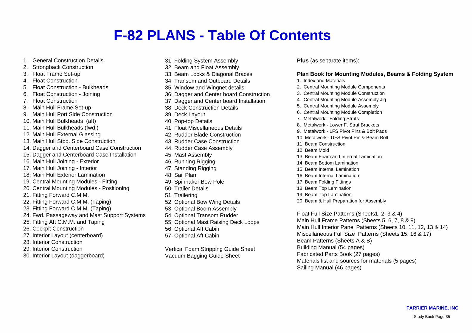
F-82 PLANS - Table Of Contents
1. General Construction Details2. Strongback Construction3. Float Frame Set-up4. Float Construction5. Float Construction - Bulkheads6. Float Construction - Joining7. Float Construction8. Main Hull Frame Set-up9. Main Hull Port Side Construction10. Main Hull Bulkheads (aft) 11. Main Hull Bulkheads (fwd.) 12. Main Hull External Glassing13. Main Hull Stbd. Side Construction 14. Dagger and Centerboard Case Construction 15. Dagger and Centerboard Case Installation16. Main Hull Joining - Exterior17. Main Hull Joining - Interior18. Main Hull Exterior Lamination19. Central Mounting Modules - Fitting20. Central Mounting Modules - Positioning 21. Fitting Forward C.M.M.22. Fitting Forward C.M.M. (Taping)23. Fitting Forward C.M.M. (Taping)24. Fwd. Passageway and Mast Support Systems25. Fitting Aft C.M.M. and Taping26. Cockpit Construction27. Interior Layout (centerboard)28. Interior Construction29. Interior Construction30. Interior Layout (daggerboard)
31. Folding System Assembly32. Beam and Float Assembly33. Beam Locks & Diagonal Braces34. Transom and Outboard Details35. Window and Wingnet details36. Dagger and Center board Construction37. Dagger and Center board Installation38. Deck Construction Details39. Deck Layout40. Pop-top Details41. Float Miscellaneous Details42. Rudder Blade Construction43. Rudder Case Construction44. Rudder Case Assembly45. Mast Assembly46. Running Rigging47. Standing Rigging48. Sail Plan49. Spinnaker Bow Pole50. Trailer Details51. Trailering52. Optional Bow Wing Details53. Optional Boom Assembly54. Optional Transom Rudder55. Optional Mast Raising Deck Loops56. Optional Aft Cabin57. Optional Aft Cabin
Vertical Foam Stripping Guide SheetVacuum Bagging Guide Sheet
Plus (as separate items):
Plan Book for Mounting Modules, Beams & Folding System1. Index and Materials2. Central Mounting Module Components3. Central Mounting Module Construction4. Central Mounting Module Assembly Jig5. Central Mounting Module Assembly6. Central Mounting Module Completion7. Metalwork - Folding Struts8. Metalwork - Lower F. Strut Brackets9. Metalwork - LFS Pivot Pins & Bolt Pads10. Metalwork - UFS Pivot Pin & Beam Bolt11. Beam Construction12. Beam Mold13. Beam Foam and Internal Lamination14. Beam Bottom Lamination15. Beam Internal Lamination16. Beam Internal Lamination17. Beam Folding Fittings18. Beam Top Lamination19. Beam Top Lamination20. Beam & Hull Preparation for Assembly
Float Full Size Patterns (Sheets1, 2, 3 & 4)Main Hull Frame Patterns (Sheets 5, 6, 7, 8 & 9)Main Hull Interior Panel Patterns (Sheets 10, 11, 12, 13 & 14)Miscellaneous Full Size Patterns (Sheets 15, 16 & 17)Beam Patterns (Sheets A & B)Building Manual (54 pages)Fabricated Parts Book (27 pages)Materials list and sources for materials (5 pages)Sailing Manual (46 pages)
FARRIER MARINE, INC
Study Book Page 35

72. Comp. Hatch Slide73. Comp. Hatch Slide Trim74. Comp. Hatch Cover75. Comp. Hatch Assembly76. Opt. Molded Outboard Bracket77. Opt. Interior layouts78. Opt. Bow Wing79 Carbon Traveler80. Aft Mast Support81. Trailer82. Trailering83. Mast Raising Procedure84. Folding Details
Appendix A : BulkheadsAppendix B : Misc. PanelsAppendix C : Misc. Panels LaminationAppendix D : Interior PanelsAppendix E : Beam Location JigAppendix F : Beam Mount DetailsAppendix G : Ready Built Beam DetailsAppendix H : Bush and Pin DetailsAppendix I : Beam Retaining Bracket DetailsAppendix J : Tankage Details
FULL SIZE PATTERNS (FSP)
Float FSP (Sheets1, 2, 3 & 4)F-32A Main Hull FSP (Sheets 5 to 13)or F-32AX Main Hull FSP (Sheets 5 to 14)F-32A Miscellaneous FSP Sheets 14 to 18 or F-32AX Miscellaneous FSP Sheets 15 to 19
Beam Construction Plan BookBeam Full Size Patterns Sheets A & B (Ready made beams are recommended)
Building Manual Fabricated Parts Book (56 Pages)Materials list Sailing Manual
F-32 Table Of Contentsiii. Vertical Foam Strippingiv. Vacuum baggingv Laminating Notesvi Material and Lam. Options
1. General Construction Details2. Strongback Construction3. Float Frame Set-up4. Float Construction5. Float Construction - Bulkheads6. Float Construction - Joining7. Float Construction8. Main Hull Frame Set-up9. Main Hull Port Side Construction10. Main Hull Bulkheads 11. Main Hull Bulkheads 12. Main Hull External Glassing13. Main Hull Stbd. Side Construction 14. Daggerboard Case Construction 15. Daggerboard Case Installation16. Main Hull Joining - Exterior17. Main Hull Joining - Interior18. Main Hull Exterior Lamination19. Cockpit Construction20. Fitting Beam Mounts21. Fitting Beam Mounts22. Fitting Forward Beam Mounts22A. Fitting Forward Beam Mounts23. Forward Beam Mount Exterior24. Fitting Aft Beam Mounts24A. Fitting Aft Beam Mounts25. Aft Beam Mount Exterior26. Stern Construction27. F-32A Interior28. Interior Construction 29. Interior Construction30. F-32AX Interior31. Folding System Assembly32. Beam to Hull Assembly
33. Beam to Float Assembly34. Beam Assembly Details35. Window and Wingnet details36. Daggerboard Construction37. Daggerboard Installation38. Deck Details39. Deck Layout40. Mast Raising Deck Details41. Float Miscellaneous Details42. Daggerboard Rudder Blade43. D/b Rudder Case Assembly44. D/b Rudder Assembly on boat45. Boom Details46. Mast Details47. Mast Setup48. Body View and Rigging49. Sail Plan50. Spinnaker Bow Pole51. Bow Pole Tube52. Bow Pole53. Bow Pole Installation54. Electrical System55. Optional Inboard56. Carbon Fiber Chainplates57 Carbon Fiber Chainplates Fitting58. Rudder Transom Brackets59. Rudder Bracket Fitting60. Rudder Blade61. Rudder Blade62. Rudder Sleeve63. Rudder Sleeve64. Rudder Case65. Rudder Case66. Rudder Case67. Tiller68. Opt. Fixed Rudder69. Companion Hatch Former70. Comp. Hatch Rail71. Comp. Hatch Rail
(ii)August 2nd, 2008
Study Book Page 36 Latest F-39 Table Of Contents can be downloaded from Study Site

FORM FRAMES
❒ Temporary Form Frames to be set up vertical, at correct distance apart, aligned with center string, and with top edges(representing float centerline) exactly level fore and aft andathwartships (across Strong Back). Packing pieces can be used toachieve this on Frame bottom edges if required.
❒ Screw frames to FORWARD side of spreader cleats. Doublebrace both sides of beam bulkheads to ensure these cannot move.Remaining frames are held vertical by a stringer each side.❒ Fit battens for foam planking, longer at stern as required.
PLANKING
❒ Planking can now begin. Follow instructions as given in Manualand Sheet iii. Edges along deck and keel to be sanded or planed flat,to be flush with top edges of temporary frames (float centerline).Float halves are glued together later, along this line.
❒ Fwd. planking ends flush with front edge of Frame 1. Final bowshape is later formed in foam and glassed over. This gives a goodability to absorb impacts. Leave stern planking long and then cut tocorrect profile by using template.
❒ Leave float ends open at this time for access later when tapinghalves together. If wished, fit High density inserts (sheet 6) now.
❒ Smooth inside surface & apply the correct internal fabric (Sht.1)
❒ One extra 250/10" wide strip down center as shown (Don't omit).
❒ One layer of A centered on Frames 6 & 12 .
❒ Fit foam stringer in bow as shown and bed on putty mixture.
❒ Two layers A BD 200 x 600 (8" x 24") centered at Frame 6 andcovering stringer.
❒ Run 1 layer D 100mm/4" wide UD tape by 3660 (12' long) on topof stringer and then cover with 1 layer A 250/10" wide,
Foam stringer, as above, 3500(11' 6") long, positioned 25mm(1") back from bow edge. Fitone stringer on each float half.
Copyright Reserved © 2004 by Farrier Marine All Metric Dimensions are in Millimetres
FLOAT CONSTRUCTIONDETAILS
F-32 Sheet 4
Stern shape template fromFull Size Patterns 3 and 4.Use to mark stern shapewhile horizontal and locatedby Frame 13.
19 (3/4")45°
1205"
Planking to be cut flush withFrame 1 at bow
1 layer 600 (24") wide band of ABD fabric at both beam bulkheads,fibers must be 0 - 90° as shown
Revised August 26th, 2004
D UD tape full length of foamstringer as specified. Covered withone layer of A
Two layers A on top of stringerand under uni-dir.
12
6
350(14")
350(14")
To center offoam stringer
One extra layer of internalfabric, 250/10" wide,3600/142" long, centeredbetween deck and keel,running between beam areasas shown. Fibers must be 0° -90° as shown (or 90°/vert. ifuni-dir.- same as first layer)
14
56
78
910
1112
13
Take particular care that BeamBulkheads (6 & 12) are set upexactly vertical. Use bracesboth sides
Fit temporary bracesto hold vertical
Spreader Cleat
4
123
Center string
NOTE: High density inserts, asdetailed on Sheet 6, can be fittedat this stage, prior to interiorlaminate. Probably easier to dohere - but be sure they are oncorrect sides
Mark bulkhead positions onstrips as planking proceeds.This makes it easier toposition bulkheads later.
A Design By Farrier Marine
Note: Lines drawnare for illustrationonly, and are notintended to showorientation of strips.
Start first foreand aft striphere
Leave stern planking long -should extend 460mm/18"past Frame 14 before triming
A: 600gm (18oz) B.D (0-90°)B: 400gm (12oz) B.D. (0-90°)C: 600gm (18oz) D.B. (45-45°)D: 400/430gm (12/13oz) UD
Study Book Page 37

Shape as shown onFloat Full Size Patterns.
Where foam varies frombasic hull shape it canbe left unlaminated andbent into shape afterremoving hull from formframes. Leave bulkheadtop areas untaped andfill any gaps later
8
11
Bulkhead Detail
All Float bulkheads are bedded in position on a 100mm/4"wide strip of DBM1708 with a large putty fillet, shaped asshown. Bulkheads are pre-laminated and then taped inposition with 150mm (6") DBM1708 tape (or equivalent -See Sheet V) on both sides
Float bulkheads are cut to size asper full size patterns. Material tobe as specified on Sheet 1, plusextra laminations as specified onFull Size Patterns
Hull side
DBM1708 Tape (or equivalent)
❒ BeamBulkheads are locatedwith their aft edges aligned with aftedges of Form Frames 5, and 11. Notched to fit over foam stringers.Bulkheads are flipped vertically innext float half (Stbd. outer side)
❒ Shroud Bulkhead: Positionedand angled forward at top asdetailed above, to align withshroud. H.D. insert and extra laminate forchainplate (as detailed on FullSize Patterns and Sheet 57) is onouter side of bulkhead as shown.Will be reversed in next float half.
Build Port Inner and Starboard outer sides first, thenreverse Form Frames to build matching sides.
FITTING BULKHEADS (Port Inner Float Side shown)
F-39 Sheet 5
All Metric Dimensions are in Millimetres
Generous PuttyFillet
Revised July 23rd, 2004
Bulkhead
16mm5/8" min.
A Design By Farrier Marine
Float halves are removed once bulkheadsare fitted. Seal or glass outside of hullbefore storing. Do not leave in sun.
❒ 16mm (5/8") thick H.D. foam or marineply Web pads, 300mm/12" long, edges at45° flush with foam stringer edges. Positionone (4 per float half) each side of both fwd.and aft beam bulkheads. Bed on putty andGlass over with two layers 600gm (18oz)B.D. 450 x 250 (18 x 10")
Putty Fillet
5
DBM1708100mm/4" tape
893 1/2"
8
Deck
Keel
OUTER HALF INNER HALF
FLOAT DECK SHAPE OPTIONTo give a flatter walking area, along with a higher and built in wingnet mounting point - See Sheet 37 & 38. Shape as shown on F.S.
Patterns and above - alternatively two opposite sets of Form Framescan be made if wished, but this is not necessary. Should extend from
635/25" in front of Frame 11 to 300/12" aft of Frame 5
Outer hull half has foam extendedabove centerline by 261 (10 1/4")
Inner hull half has foamextended up as shownbetween Frames 5 & 11
❒ Use an extra layer oftape on chainplate side onlyfor top half of bulkhead(both sides)
Copyright Reserved © 2001 by Farrier Marine, IncStudy Book Page 38
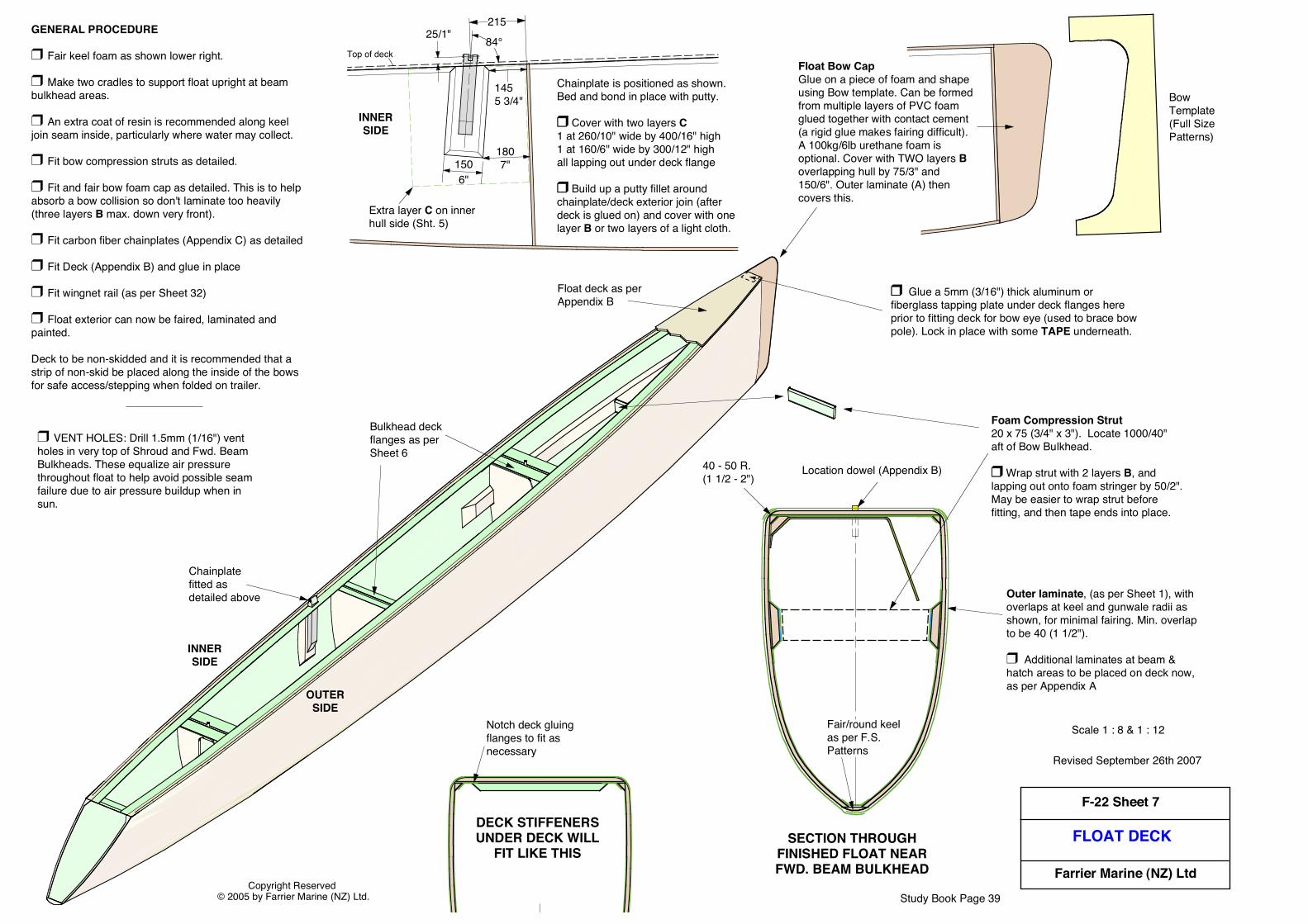
FLOAT DECK
Copyright Reserved © 2005 by Farrier Marine (NZ) Ltd.
F-22 Sheet 7
Farrier Marine (NZ) Ltd
Location dowel (Appendix B)
Study Book Page 39
1807"
1455 3/4"
1506"
84°
Extra layer C on inner hull side (Sht. 5)
25/1"
Chainplate is positioned as shown. Bed and bond in place with putty.
❒ Cover with two layers C1 at 260/10" wide by 400/16" high1 at 160/6" wide by 300/12" highall lapping out under deck flange
❒ Build up a putty fillet around chainplate/deck exterior join (after deck is glued on) and cover with one layer B or two layers of a light cloth.
INNERSIDE
Float Bow CapGlue on a piece of foam and shape using Bow template. Can be formed from multiple layers of PVC foam glued together with contact cement (a rigid glue makes fairing difficult). A 100kg/6lb urethane foam is optional. Cover with TWO layers B overlapping hull by 75/3" and 150/6". Outer laminate (A) then covers this.
Bow Template (Full Size Patterns)
Top of deck
215
SECTION THROUGHFINISHED FLOAT NEARFWD. BEAM BULKHEAD
40 - 50 R.(1 1/2 - 2")
Fair/round keel as per F.S. Patterns
Outer laminate, (as per Sheet 1), with overlaps at keel and gunwale radii as shown, for minimal fairing. Min. overlap to be 40 (1 1/2").
❒ Additional laminates at beam & hatch areas to be placed on deck now, as per Appendix A
Location dowel (Appendix B)
DECK STIFFENERSUNDER DECK WILL
FIT LIKE THIS
Notch deck gluing flanges to fit as necessary
Scale 1 : 8 & 1 : 12
Revised September 26th 2007
❒ VENT HOLES: Drill 1.5mm (1/16") vent holes in very top of Shroud and Fwd. Beam Bulkheads. These equalize air pressure throughout float to help avoid possible seam failure due to air pressure buildup when in sun.
Foam Compression Strut20 x 75 (3/4" x 3"). Locate 1000/40" aft of Bow Bulkhead.
❒ Wrap strut with 2 layers B, and lapping out onto foam stringer by 50/2".May be easier to wrap strut before fitting, and then tape ends into place.
GENERAL PROCEDURE
❒ Fair keel foam as shown lower right.
❒ Make two cradles to support float upright at beam bulkhead areas.
❒ An extra coat of resin is recommended along keel join seam inside, particularly where water may collect.
❒ Fit bow compression struts as detailed.
❒ Fit and fair bow foam cap as detailed. This is to help absorb a bow collision so don't laminate too heavily (three layers B max. down very front).
❒ Fit carbon fiber chainplates (Appendix C) as detailed
❒ Fit Deck (Appendix B) and glue in place
❒ Fit wingnet rail (as per Sheet 32)
❒ Float exterior can now be faired, laminated and painted.
Deck to be non-skidded and it is recommended that a strip of non-skid be placed along the inside of the bows for safe access/stepping when folded on trailer.
Float deck as per Appendix B
Bulkhead deck flanges as per Sheet 6
Chainplate fitted as detailed above
INNERSIDE
OUTERSIDE
❒ Glue a 5mm (3/16") thick aluminum or fiberglass tapping plate under deck flanges here prior to fitting deck for bow eye (used to brace bow pole). Lock in place with some TAPE underneath.

STARBOARD HULL SIDECONSTRUCTION
F-39 Sheet 14
A Design By Farrier Marine
Copyright Reserved © 2001 by Farrier Marine, Inc
14
11
7
11
12
14
15
7
12
6
6
2
5
5
2
❒ Bow bulkhead as per Sheet 11
❒ Aft Beam Sub Bulkhead - same as Sheet 10
1636 3/8"
180/7"
1104 1/4"
Revised October 25, 2001
❒ Aft Beam Bulkhead - same as Sheet 11, but with doorway. Fitted after hull L.F.S. anchors.
❒ Stern Sub-bulkhead as per Sheet 10
❒ Transom - same as Sheet 10 - take care that center edge is aligned correctly to match port side
❒ Main Cabin Aft Bulkhead - same as Sheet 10 but with doorway
❒ Main Cabin Forward Bulkhead as per Sheet 10, but with doorway. D/b version shown.
❒ Extra laminate as per Sheet 10
Aft Cockpit bulkhead will be located here
❒ Fwd. Beam Bulkhead. Fit as per Sheet 11 (after hull L.F.S. anchors).
❒ Forward Beam Sub - Bulkhead. Same as Sheet 11
2409 1/2"
❒ Fwd. Bunk Aft Bulkhead - same as Sheet 11
❒ Fwd. Cabin Bulkhead - same as Sheet 11
See Sheets 25 to 26 forAft Cockpit Version
❒ Extra laminate as per Sheet 10
❒ Extra laminate as per Sheet 10
❒ Fit all H.D. inserts and same extra laminates etc. as specified on Sheets 9, 10 and 11
For the most accurate alignment at center join, bulkhead areas near centerline can be left unglassed until after joining the two hull halves.
174
Study Book Page 40
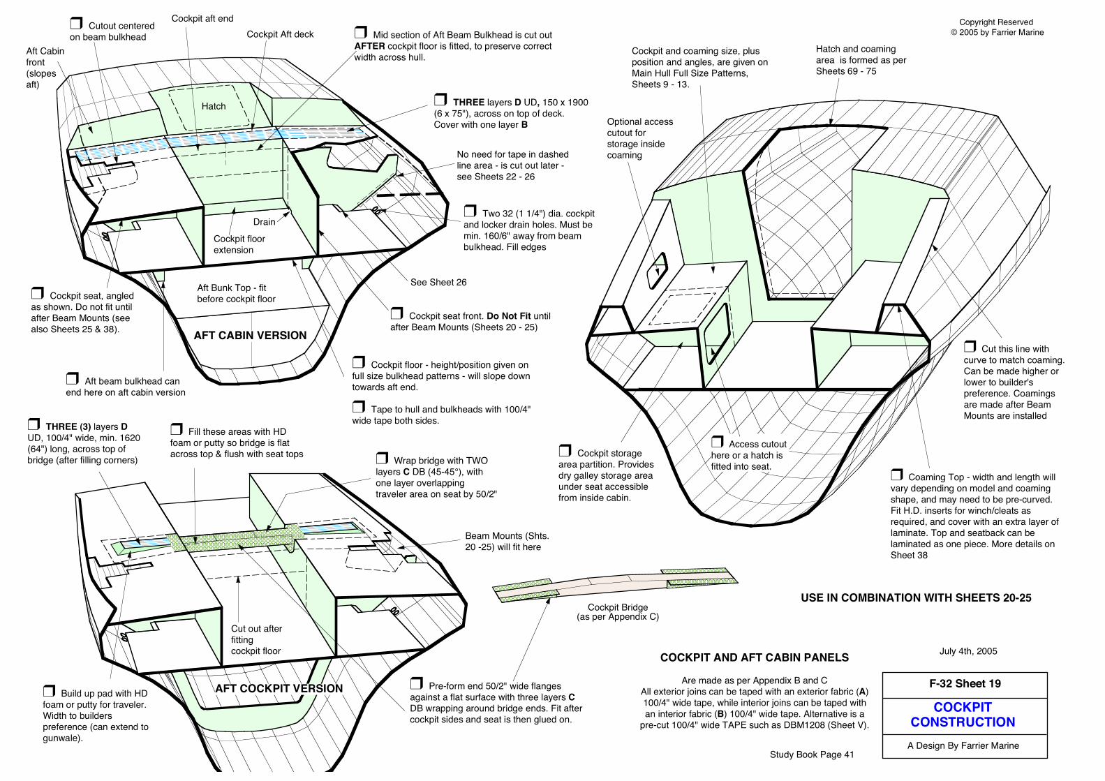
COCKPITCONSTRUCTION
F-32 Sheet 19
A Design By Farrier Marine
Copyright Reserved © 2005 by Farrier Marine
July 4th, 2005
❒ Cockpit floor - height/position given on full size bulkhead patterns - will slope down towards aft end.
❒ Tape to hull and bulkheads with 100/4" wide tape both sides.
❒ Two 32 (1 1/4") dia. cockpit and locker drain holes. Must be min. 160/6" away from beam bulkhead. Fill edges
❒ Cockpit seat, angled as shown. Do not fit until after Beam Mounts (see also Sheets 25 & 38).
❒ Cockpit seat front. Do Not Fit until after Beam Mounts (Sheets 20 - 25)
❒ Cut this line with curve to match coaming. Can be made higher or lower to builder's preference. Coamings are made after Beam Mounts are installed
❒ Coaming Top - width and length will vary depending on model and coaming shape, and may need to be pre-curved. Fit H.D. inserts for winch/cleats as required, and cover with an extra layer of laminate. Top and seatback can be laminated as one piece. More details on Sheet 38
❒ Cockpit storage area partition. Provides dry galley storage area under seat accessible from inside cabin.
Optional access cutout for storage inside coaming
Hatch and coaming area is formed as per Sheets 69 - 75
❒ Access cutout here or a hatch is fitted into seat.
Cockpit and coaming size, plus position and angles, are given on Main Hull Full Size Patterns, Sheets 9 - 13.
COCKPIT AND AFT CABIN PANELS
Are made as per Appendix B and CAll exterior joins can be taped with an exterior fabric (A)100/4" wide tape, while interior joins can be taped withan interior fabric (B) 100/4" wide tape. Alternative is a
pre-cut 100/4" wide TAPE such as DBM1208 (Sheet V).
❒ Mid section of Aft Beam Bulkhead is cut out AFTER cockpit floor is fitted, to preserve correct width across hull.
Aft Bunk Top - fit before cockpit floor
❒ Cutout centered on beam bulkhead
❒ THREE layers D UD, 150 x 1900 (6 x 75"), across on top of deck. Cover with one layer B
❒ Aft beam bulkhead can end here on aft cabin version
Cockpit aft endCockpit Aft deck
Cockpit floor extension
Aft Cabin front (slopes aft)
See Sheet 26
Drain
No need for tape in dashed line area - is cut out later - see Sheets 22 - 26
Hatch
❒ Pre-form end 50/2" wide flanges against a flat surface with three layers C DB wrapping around bridge ends. Fit after cockpit sides and seat is then glued on.
❒ THREE (3) layers D UD, 100/4" wide, min. 1620 (64") long, across top of bridge (after filling corners)
❒ Fill these areas with HD foam or putty so bridge is flat across top & flush with seat tops
AFT CABIN VERSION
Cockpit Bridge(as per Appendix C)
USE IN COMBINATION WITH SHEETS 20-25
Cut out after fitting cockpit floor
❒ Wrap bridge with TWO layers C DB (45-45°), with one layer overlapping traveler area on seat by 50/2"
AFT COCKPIT VERSION❒ Build up pad with HD foam or putty for traveler. Width to builders preference (can extend to gunwale).
Beam Mounts (Shts. 20 -25) will fit here
Study Book Page 41
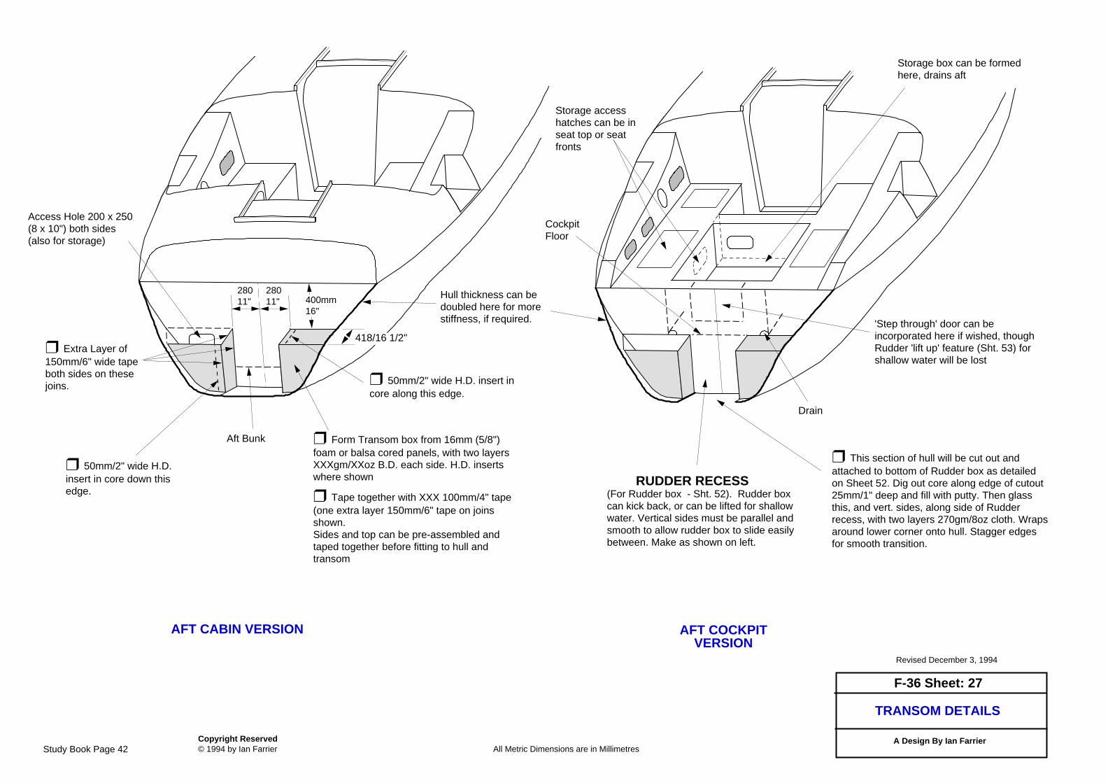
TRANSOM DETAILS
F-36 Sheet: 27
All Metric Dimensions are in Millimetres
Revised December 3, 1994
Copyright Reserved © 1994 by Ian Farrier
❒ This section of hull will be cut out andattached to bottom of Rudder box as detailedon Sheet 52. Dig out core along edge of cutout25mm/1" deep and fill with putty. Then glassthis, and vert. sides, along side of Rudderrecess, with two layers 270gm/8oz cloth. Wrapsaround lower corner onto hull. Stagger edgesfor smooth transition.
RUDDER RECESS(For Rudder box - Sht. 52). Rudder boxcan kick back, or can be lifted for shallowwater. Vertical sides must be parallel andsmooth to allow rudder box to slide easilybetween. Make as shown on left.
❒ 50mm/2" wide H.D.insert in core down thisedge.
A Design By Ian Farrier
Hull thickness can bedoubled here for morestiffness, if required.
28011"
28011" 400mm
16"
Access Hole 200 x 250(8 x 10") both sides(also for storage)
Aft Bunk ❒ Form Transom box from 16mm (5/8")foam or balsa cored panels, with two layersXXXgm/XXoz B.D. each side. H.D. insertswhere shown
❒ Tape together with XXX 100mm/4" tape(one extra layer 150mm/6" tape on joinsshown. Sides and top can be pre-assembled andtaped together before fitting to hull andtransom
❒ Extra Layer of150mm/6" wide tapeboth sides on thesejoins.
418/16 1/2"
AFT CABIN VERSION AFT COCKPITVERSION
'Step through' door can beincorporated here if wished, thoughRudder 'lift up' feature (Sht. 53) forshallow water will be lost
CockpitFloor
Drain
Storage accesshatches can be inseat top or seatfronts
Storage box can be formedhere, drains aft
❒ 50mm/2" wide H.D. insert incore along this edge.
Study Book Page 42

Study Book Page 43
RESINS: The basic choice is between epoxy and polyester. Epoxy is the best and strongest, but also the most expensive, and only epoxy should be used with wood. Polyester or vinylester (better) can be used with foam core construction, and most production boats use polyester or vinylester resins
FIBERGLASS: There are many different variations possible, and the basic requirement is an E glass, compatible with the type of resin being used. Other reinforcing materials that may be used include:Carbon Fiber: Not essential, but recommended for a number of key areas for the high strength to weight ratio possible, and better long term fatigue properties compared to fiberglass. The complete boat can also be built in carbon fiber, and guidelines on how to do this are included in the plans. Kevlar: Again not essential, but a good choice for some hull and other areas to take advantages of the high tensile strength, and excellent puncture/abrasion resistance. Guidelines on where to use Kevlar are also included in the plans.
BALSA CORE: has a number of advantages in high load areas where a lightweight core with very high mechanical properties are required. Very good for daggerboard case sides, or deck areas for instance.
OTHER MATERIALS AND METHODSMany different materials and methods have been investigated, tried, and used over the past 30 years and these include:
SHEET PLY: Once the most common way of building your own boat. The materials are readily available, well proven, and most builders are familiar with it. The disadvantage is the room taken by the stringers and frames inside, the additional labor required, the additional weight, the potential for rot problems, and lower resale value. The early Trailertri designs used this method, but it has now been discarded by superior strip planking methods.
CYLINDER MOLDING: Similar to tortured ply, which was tried but discarded for the Trailertri 18 back in 1974. It is difficult to achieve consistent shapes, the process being unreliable, and the many additional stringers and bulkheads required to be fitted later take too long, more than eliminating any initial time savings, while reducing interior space.
CONSTANT CAMBER: This can be a very useful and quick method of boat building for boats with basic or limited hull shapes. However, more advanced hull shapes such as used in the latest F-boat designs cannot be built this way. Modern strip planking systems have now overtaken this method, and are thus now generally favored and used by most professional boat builders.
ALUMINUM: Not practical for small multihulls, the minimum skin thickness being too heavy compared to other materials, while welds can be troublesome and fatigue prone. Only for very large multihulls, and even then very out of favor.
COLD MOLDED: An older labor intensive method, with literally thousands of veneer or ply strips to be cut. Seldom used now.
FOAM SANDWICH - MALE MOLDED - The original way of building a foam core hull. However, laying foam over a male mold is awkward and much too
The latest F-Series designs feature a unique method of building the hulls split vertically down the center, in simple female form frames. This halves the amount of work required for temporary building frames. The Full Size Patterns are only used once, there being no need to mark their reverse side and then flip them over for marking the opposite hull side. The building frames are instead just flipped around to build the other hull half - much easier and faster - half the work in fact.
Once both hull halves are complete, they are joined down the centerline, the ideal place for extra reinforcement. Gunwale is no longer a join, and can thus be clean and well rounded. The considerable time required to later 'frame up' for the deck and cabin is also avoided. Recommended materials are as follows:
FOAM: Foam core will give the lightest and most durable boat and correct type is a PVC or polymer (SAN) foam of the correct density (usually 80kg/5lb). Suitable brands include Divinycell, Herex, Klegecell and Corecell. Foam has the advantage that either epoxy of polyester resin can be used, which can be an important advantage to those that may suffer from an epoxy allergy. Detailed general information about building with foam is covered in the Farrier Building Manual and Plans, plus most foam manufacturers will provide material on the various basic techniques and recommended practices on request.The advantages of foam core include a significantly lighter boat, durability, no tendency for strips to move with differing humidity levels while building (which can be a problem with wood strips), and excellent insulation properties.
WESTERN RED CEDAR : A light and durable wood, that is very popular for wood stripping. May be more economical than foam, but can also now be more expensive in many areas. It will give a heavier boat, but is a familiar material to many and pleasant to work with. Another wood alternative is DuraKore, which is a balsa core laminated between wood veneers, to form a composite strip for strip planking. Can be slightly lighter than cedar for hulls thicker than 12mm (1/2”), but still heavier than foam.
CONSTRUCTION - MATERIALS
labor intensive. It was used for the prototype F-27, with an excellent result, but the labor required discouraged its use for many years, wood strip planking being preferred, even though heavier. However, the development of vertical foam stripping in female form frames has now made foam the best choice.
PRE-MOLDED FOAM/GLASS PANELS - A recent development and a good choice for hard chine hulls, but such hulls do have some limitations in both performance and interior room. Final fairing of exterior seams still remains a problem, as does the resale value of hard chine hulls. Bare hulls are also a relatively quick part of building so any time savings overall are small.
MATERIALS LIST One of the most underestimated items of importance, as looking or going for unlisted items can be one of the biggest time wasters in the building of any boat. A materials list can range from just one or two pages of basic building materials to a full production boat material list which has to list every little thing from a simple cotter pin to the largest bolt. This is a critical aspect of building any boat efficiently - accurate costing and having the parts there when needed. The same applies to any 'one off' boat, and while the materials lists for Farrier plans are not as extensive as a true production list, they are probably the most comprehensive available, being based on a production type system, with at least five to six pages covering all building materials and fitout. It should also be noted that underestimating or omitting materials from any design's materials list does not make it any cheaper to build. Those missing materials still have to be purchased at some stage.Just to get started, you only need a small quantity of foam or wood, plus fiberglass and resin, and you can then get an idea if boat building is for you, before making a large outlay.Cost of MaterialsThis can vary tremendously from builder to builder, and a good rule of thumb is around 50% of an equivalent standard production boat. Some builders can do better, others worse. It is important to look for discounts, and not waste materials. Some builders can use twice as much resin as others, and their boat ends up significantly heavier as well.If budget is restricted, premium materials are not necessary, as the high safety factors used allow for lower grade materials. Polyester resins for instance can cost half that of epoxies Skilled builders using premium materials (such as epoxy) could in fact lighten off many areas by around 10%, using 16oz fabric instead of 18oz for example.
Vertical foam stripped F-25A float hull in vertically split female formframes - note how wide strips can be
A completed F-9A hull half in foam strip planking and ready for bulkheads to be fitted
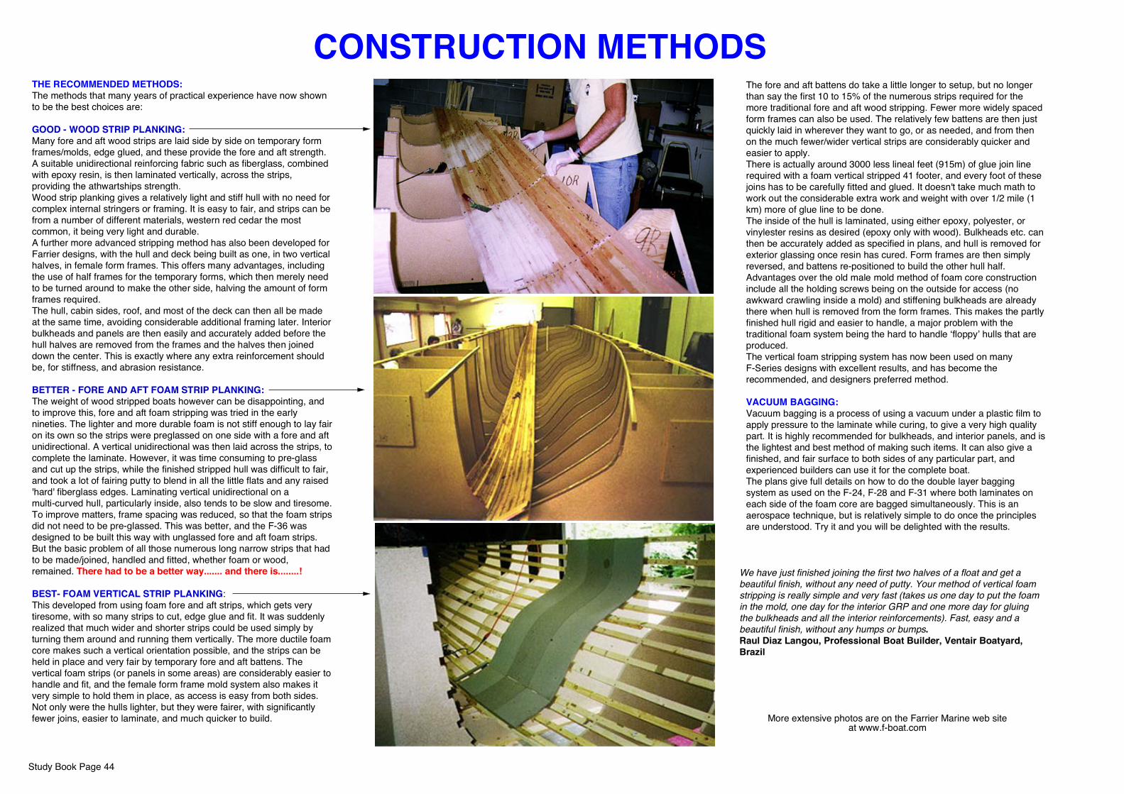
Study Book Page 44
CONSTRUCTION METHODSTHE RECOMMENDED METHODS:The methods that many years of practical experience have now shown to be the best choices are:
GOOD - WOOD STRIP PLANKING: Many fore and aft wood strips are laid side by side on temporary form frames/molds, edge glued, and these provide the fore and aft strength. A suitable unidirectional reinforcing fabric such as fiberglass, combined with epoxy resin, is then laminated vertically, across the strips, providing the athwartships strength.Wood strip planking gives a relatively light and stiff hull with no need for complex internal stringers or framing. It is easy to fair, and strips can be from a number of different materials, western red cedar the most common, it being very light and durable.A further more advanced stripping method has also been developed for Farrier designs, with the hull and deck being built as one, in two vertical halves, in female form frames. This offers many advantages, including the use of half frames for the temporary forms, which then merely need to be turned around to make the other side, halving the amount of form frames required.The hull, cabin sides, roof, and most of the deck can then all be made at the same time, avoiding considerable additional framing later. Interior bulkheads and panels are then easily and accurately added before the hull halves are removed from the frames and the halves then joined down the center. This is exactly where any extra reinforcement should be, for stiffness, and abrasion resistance.
BETTER - FORE AND AFT FOAM STRIP PLANKING: The weight of wood stripped boats however can be disappointing, and to improve this, fore and aft foam stripping was tried in the early nineties. The lighter and more durable foam is not stiff enough to lay fair on its own so the strips were preglassed on one side with a fore and aft unidirectional. A vertical unidirectional was then laid across the strips, to complete the laminate. However, it was time consuming to pre-glass and cut up the strips, while the finished stripped hull was difficult to fair, and took a lot of fairing putty to blend in all the little flats and any raised 'hard' fiberglass edges. Laminating vertical unidirectional on a multi-curved hull, particularly inside, also tends to be slow and tiresome.To improve matters, frame spacing was reduced, so that the foam strips did not need to be pre-glassed. This was better, and the F-36 was designed to be built this way with unglassed fore and aft foam strips. But the basic problem of all those numerous long narrow strips that had to be made/joined, handled and fitted, whether foam or wood, remained. There had to be a better way....... and there is........!
BEST- FOAM VERTICAL STRIP PLANKING:This developed from using foam fore and aft strips, which gets very tiresome, with so many strips to cut, edge glue and fit. It was suddenly realized that much wider and shorter strips could be used simply by turning them around and running them vertically. The more ductile foam core makes such a vertical orientation possible, and the strips can be held in place and very fair by temporary fore and aft battens. The vertical foam strips (or panels in some areas) are considerably easier to handle and fit, and the female form frame mold system also makes it very simple to hold them in place, as access is easy from both sides. Not only were the hulls lighter, but they were fairer, with significantly fewer joins, easier to laminate, and much quicker to build.
The fore and aft battens do take a little longer to setup, but no longer than say the first 10 to 15% of the numerous strips required for the more traditional fore and aft wood stripping. Fewer more widely spaced form frames can also be used. The relatively few battens are then just quickly laid in wherever they want to go, or as needed, and from then on the much fewer/wider vertical strips are considerably quicker and easier to apply.There is actually around 3000 less lineal feet (915m) of glue join line required with a foam vertical stripped 41 footer, and every foot of these joins has to be carefully fitted and glued. It doesn't take much math to work out the considerable extra work and weight with over 1/2 mile (1 km) more of glue line to be done.The inside of the hull is laminated, using either epoxy, polyester, or vinylester resins as desired (epoxy only with wood). Bulkheads etc. can then be accurately added as specified in plans, and hull is removed for exterior glassing once resin has cured. Form frames are then simply reversed, and battens re-positioned to build the other hull half.Advantages over the old male mold method of foam core construction include all the holding screws being on the outside for access (no awkward crawling inside a mold) and stiffening bulkheads are already there when hull is removed from the form frames. This makes the partly finished hull rigid and easier to handle, a major problem with the traditional foam system being the hard to handle ‘floppy’ hulls that are produced.The vertical foam stripping system has now been used on many F-Series designs with excellent results, and has become the recommended, and designers preferred method.
VACUUM BAGGING:Vacuum bagging is a process of using a vacuum under a plastic film to apply pressure to the laminate while curing, to give a very high quality part. It is highly recommended for bulkheads, and interior panels, and is the lightest and best method of making such items. It can also give a finished, and fair surface to both sides of any particular part, and experienced builders can use it for the complete boat.The plans give full details on how to do the double layer bagging system as used on the F-24, F-28 and F-31 where both laminates on each side of the foam core are bagged simultaneously. This is an aerospace technique, but is relatively simple to do once the principles are understood. Try it and you will be delighted with the results.
More extensive photos are on the Farrier Marine web siteat www.f-boat.com
We have just finished joining the first two halves of a float and get a beautiful finish, without any need of putty. Your method of vertical foam stripping is really simple and very fast (takes us one day to put the foam in the mold, one day for the interior GRP and one more day for gluing the bulkheads and all the interior reinforcements). Fast, easy and a beautiful finish, without any humps or bumps.Raul Diaz Langou, Professional Boat Builder, Ventair Boatyard, Brazil

Study Book Page 45
Farrier designs have been built by many with no previous experience, and the plans have been drawn specifically for amateur builders, with detailed step by step procedures. Only basic practical skills are required, along with some knowledge of simple boat building procedures, and these are covered in the Building Manual and plans. Hiring a good boatbuilder for a few days can also get you started and demonstrate the various techniques.
There is some metalwork involved, but most of this is fairly basic cut and drill, and can be done with a bandsaw and drill press, or a local machine shop can be employed. Some welding is also required and this is best done by taking to an experienced welder.
Application, or the ability to get things done are far more important than a high skill level, and if you could not build or assemble something simple like a bookcase then building a boat is probably not a good idea.
Building is thus not for everyone, but if one wants the boat done a certain way, or with specific features, or a roomier boat like the F-9AX, or one just does not have the money to buy, or just wants to be sure it is built well, then building may be the best choice. However, if you do not have the full support of your spouse or family then don't even think of starting, as building any boat can take a considerable time.
It is also important to decide what sort of boat you want and then plan accordingly. If very particular, and wanting the perfect boat, and you don't mind putting in lots of time, then there is little to be said. It is going to take a while, and for many, the building can be just as enjoyable as sailing.
However, if you just want a boat to go sailing, and as quickly as possible, then it is important to just get on with it in the quickest and most efficient manner. Don't spend weeks trying to get every little piece of foam or wood to fit perfectly - under the skin it is not that important. It doesn't have to be rough either - just don't try and get everything perfect, particularly with modern fillers being so readily available to fill any gaps (and they're stronger).
There are quite a few tricks in building fast, and these are covered in the Building Manual. But in the end a mental attitude of just getting the job done is the most important. The general motto should be to start fast, but finish slow, so that what you see at the end is the best part, and you don't end up with enclosed hull areas that look like furniture, while the final finish is rough from running out of patience and rushing it. Do all the rushing at the beginning, as hurrying the final finish is a major reason why many home builts can have a lower resale value, in spite of the fact they may be better built under the skin.
Experienced tradesmen such as carpenters or bricklayers tend to work very fast and can get a boat built very quickly, while more precise cabinet makers can take the longest, but it is usually a beautiful job that would not look out of place in any lounge room! Best time for an F-9A was 1600 hours (using ready made beams and folding system), but that is exceptional. The same builder then built an F-82R in around 1500 hours (making beams also this time), and he has just finished an F-9R. The finished products were excellent, very basic and light, with nothing fancy inside (flat textured paint only), but he was out sailing and winning races very quickly.
SKILLS REQUIRED "Doing it right the first time is far quicker and lessexpensive than having to do it over"
The trick is the ability to just get on with it, with minimal daydreaming, and not taking hours over some little thing that doesn't really matter. Build one step at a time, as laid out in the plans, and never put anything off till later, as this can generate a huge backlog of incomplete tasks which is bad for morale.
SIMPLE OR SOPHISTICATED - IT'S YOUR CHOICE!
Farrier plans offer a choice between relatively basic and simple boats, to more complex and very sophisticated craft. The plans are the most comprehensive available and choices included range from basic materials and many 'make it yourself' parts for keeping costs down, to highly advanced options for those who want the best and a 'state of the art' modern multihull.
Interiors are a particular trap - simple is better - wine racks, drawers, etc. or a perfectly faired and painted interior finish may be nice, but can take longer than building the hulls. The process can also be speeded up considerably by hiring skilled help along the way, as required.
SHOULD YOU BUILD?
There is much to enjoy about building a boat, and a lot of satisfaction.You also have the advantage of knowing how it is built, and once completed it can be a considerable asset, and may even prove to be a profitable undertaking. With the proven strength, and sailing reputation of Farrier designs now well established world wide, the resale value is excellent.
However, building takes patience, self discipline, the development of some new skills, and many may find there is more work than they have the patience for. This applies to all types of boats, regardless of all 'easy build' claims etc., as there is always a certain core amount of what may be boring and repetitive work that is unavoidable. But, for those with the inclination, building your own boat can be very rewarding, with a good sense of achievement. Once finished and sailing, a lot of pleasure and pride can be taken with the end result.
I received the F-82 plans today and have only had a quick look at them. Without a doubt they are the most detailed plans I have ever seen. I don't think there will be much guess work in building this boat unlike others I have built. Andrew Downing, NSW, Australia
Laminating hull side of an F-41. Laminating is fairly straight forward, and onceone has had some practice, it becomes relatively easy. Just don't try too big of an
area at one time until familiar with the process - even very large hulls can bebroken down into easy to handle small areas.
Jack Dearden starting to lay the foam strips on the hull side of his F-41. Fitting the strips is fairly straight forward, and one soon learns the various techniques and tricks required. Jack is also using some clamps to help hold in place prior to screwing.

VERTICAL FOAM STRIPPLANKING SYSTEM
FARRIER MARINE, Inc
www.f-boat.com
Any excessive edge glue on outer side can make fairing difficult
FORM FRAME
Fore and aft fairing battens, approx. 19 x 45 (3/4 x 1 3/4") set into and screwed to Form Frames. Notch can be wider or shaped as shown (no need for a neat fit)
Foam Strip (runningvertically). Can be up to600mm/24" wide
Self tapping screws hold foam to battens - length as required (to penetrate foam at least 75% of thickness)
Note that any edge glue squeezing out fairing side can make fairing foam more difficult. A hard spot develops with the soft foam being sanded away each side. If any glue squeezes out then scrape it away. Any gaps left will be filled after fairing by troweling on a putty mixture. A soft edge glue is best, and a quick setting polyurethane type glue has been used successfully, but first check that it is compatible with resin. Strength of glue is not critical, it only has to be stronger than the foam and waterproof.If a fairing problem exists due to hard and soft materials, then try using a power plane to fair that area. It can be set for a fine cut and makes no distinction between foam and glue (takes it all off regardless).
GENERAL INFORMATIONForm frames can also be cut here to avoid notching for stringers
Cut foam as required in tight corners, or heat bend using a heat gun (like a souped up hair dryer). Cuts are used to form foam in production trimaran floats, which are similar in this area.
Copyright Reserved © 1999 by Farrier Marine, Inc.
Bulkheads etc. are next added as detailed in the plans, and hull is finally removed for exterior glassing once resin has cured. Form frames are then simply reversed, and battens re-fitted to build other hull half.
Advantages over the old male mold method of foam core construction are all the screws are on the outside and stiffening bulkheads are added before hull is removed from frames. Anyone who has had to climb inside a male mold to remove screws will appreciate the external screws, and once the hull is removed, one is not presented with a huge flexible hard to handle 'whale'.
Foam can also be held temporarily in place by ply scraps screwed from this side, and replaced by screws from reverse side later before lamination
VERTICAL FOAM STRIPPING Foam stripping is a new, but now proven procedure, that has now been used on many F-9s and F-82s with excellent results. It is now the recommended and designer's preferred method. The same basic system as shown can be used on all components.
With both cedar and Durakore becoming more expensive due to rising lumber prices, foam core is now also becoming perhaps the lowest cost method in many areas. One can also use less expensive polyester or vinylester resins, and this can be an important advantage to those with an epoxy allergy.
Polyester resin properties are not as good as epoxy, while vinylesters are between the two. However, polyesters are still strong enough to be used, but either vinylester or epoxy will give a slightly stronger/tougher boat, and thus be less susceptible to damage.
Other advantages of foam core, include a significantly lighter boat, with no tendency for the strips to move with differing humidity levels, which can be a problem with Durakore.
A 5lb/80kg PVC foam should be used (do not use the weaker urethane foams - these are only suitable for non-structural areas). Also avoid contoured foam (pre-cut with scrim backing) as this takes more resin and is difficult to keep fair.
BASIC PROCEDUREThe same basic form frames are used as with either wood or foam stripping, but, with foam, full length (scarf as required) longitudinal wood stringers/battens are set into the frames every 150-250mm (6-10") and even closer in tighter corners. This also depends on stiffness of foam and experimentation will determine the best spacing. Holes (5mm - 7/32") are then drilled at random through these stringers for screws to hold the foam down from the outside. Set-up will be longer with such fore and aft stringers, but considerable time will be saved in not having to glue long fore and aft planking strips together, while the amount of edge gluing and labor is greatly reduced due to the much wider vertical strips.
Foam is cut into 150mm/6" wide strips, which seems to be a good general width. Can also be wider or narrower as the need may be (could be 600mm/24" wide or a large panel in some areas). Strips are laid in vertically, being held down by screws from the outside, or temporary staples or screws through ply scaps from inside. Foam should be partly cut longitudinally or heated to bend around tighter corners (heated foam becomes formable). Each strip is edge glued and time should be taken here to get it right, checking for fairness. A little care could save a lot of work later.
Once glue has set, any staples/screws on inside can be removed, before interior is glassed (being replaced by screws from outside as necessary). Glassing inside then proceeds, using the correct reinforcing fabrics as specified. If access is a problem in large hulls then it may be best to glass half the hull side, then the other half. This will avoid walking or kneeling on bare foam.
NOTE that Full size patterns give this line, or hull outer surface
Study Book Page 46
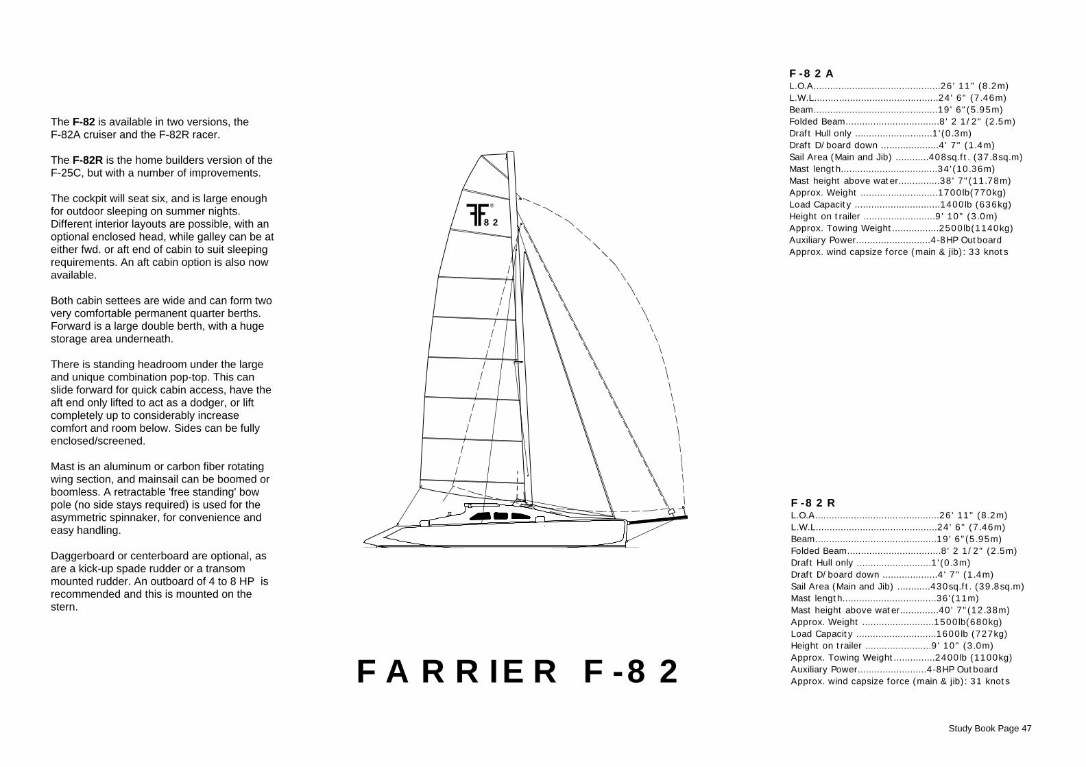
82
FARRIER F-82
F-82A L.O.A..............................................26' 11" (8.2m)L.W.L.............................................24' 6" (7.46m)Beam.............................................19' 6"(5.95m)Folded Beam..................................8' 2 1/2" (2.5m)Draft Hull only ............................1'(0.3m)Draft D/board down .....................4' 7" (1.4m)Sail Area (Main and Jib) ............408sq.ft. (37.8sq.m) Mast length...................................34'(10.36m)Mast height above water...............38' 7"(11.78m)Approx. Weight ............................1700lb(770kg) Load Capacity ...............................1400lb (636kg)Height on trailer ..........................9' 10" (3.0m)Approx. Towing Weight.................2500lb(1140kg) Auxiliary Power...........................4-8HP OutboardApprox. wind capsize force (main & jib): 33 knots
F-82R L.O.A.............................................26' 11" (8.2m)L.W.L............................................24' 6" (7.46m)Beam............................................19' 6"(5.95m)Folded Beam..................................8' 2 1/2" (2.5m)Draft Hull only ...........................1'(0.3m)Draft D/board down ....................4' 7" (1.4m)Sail Area (Main and Jib) ............430sq.ft. (39.8sq.m)Mast length..................................36'(11m)Mast height above water..............40' 7"(12.38m)Approx. Weight ..........................1500lb(680kg)Load Capacity .............................1600lb (727kg)Height on trailer ........................9' 10" (3.0m)Approx. Towing Weight...............2400lb (1100kg)Auxiliary Power.........................4-8HP OutboardApprox. wind capsize force (main & jib): 31 knots
Study Book Page 47
®
The F-82 is available in two versions, theF-82A cruiser and the F-82R racer.
The F-82R is the home builders version of theF-25C, but with a number of improvements.
The cockpit will seat six, and is large enoughfor outdoor sleeping on summer nights.Different interior layouts are possible, with anoptional enclosed head, while galley can be ateither fwd. or aft end of cabin to suit sleepingrequirements. An aft cabin option is also nowavailable.
Both cabin settees are wide and can form twovery comfortable permanent quarter berths.Forward is a large double berth, with a hugestorage area underneath. There is standing headroom under the largeand unique combination pop-top. This canslide forward for quick cabin access, have theaft end only lifted to act as a dodger, or liftcompletely up to considerably increasecomfort and room below. Sides can be fullyenclosed/screened.
Mast is an aluminum or carbon fiber rotatingwing section, and mainsail can be boomed orboomless. A retractable 'free standing' bowpole (no side stays required) is used for theasymmetric spinnaker, for convenience andeasy handling.
Daggerboard or centerboard are optional, asare a kick-up spade rudder or a transommounted rudder. An outboard of 4 to 8 HP isrecommended and this is mounted on thestern.
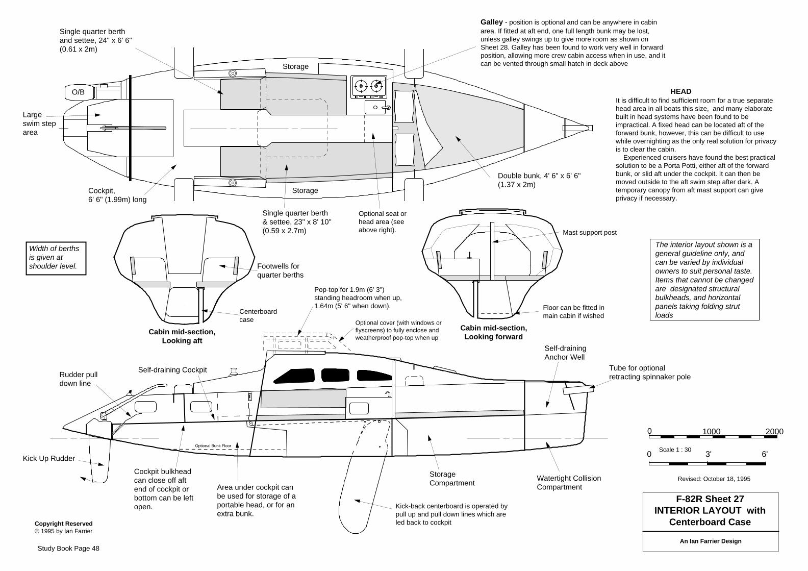
O/B
Copyright Reserved © 1995 by Ian Farrier
F-82R Sheet 27INTERIOR LAYOUT with
Centerboard Case
An Ian Farrier Design
Watertight CollisionCompartment
Self-drainingAnchor Well
StorageCompartment
Self-draining Cockpit
The interior layout shown is ageneral guideline only, andcan be varied by individualowners to suit personal taste.Items that cannot be changedare designated structuralbulkheads, and horizontalpanels taking folding strutloads
Revised: October 18, 1995
Kick Up Rudder
Width of berthsis given atshoulder level.
Double bunk, 4' 6" x 6' 6"(1.37 x 2m)
Storage
Storage
Cockpit, 6' 6" (1.99m) long
Single quarter berth& settee, 23" x 8' 10"(0.59 x 2.7m)
Scale 1 : 30
0 1000 2000
0 3' 6'
Single quarter berthand settee, 24" x 6' 6"(0.61 x 2m)
Rudder pulldown line
Tube for optionalretracting spinnaker pole
Cabin mid-section,Looking forward
Cabin mid-section,Looking aft
Largeswim steparea
Cockpit bulkheadcan close off aftend of cockpit orbottom can be leftopen.
Footwells forquarter berths
Area under cockpit canbe used for storage of aportable head, or for anextra bunk.
HEADIt is difficult to find sufficient room for a true separatehead area in all boats this size, and many elaboratebuilt in head systems have been found to beimpractical. A fixed head can be located aft of theforward bunk, however, this can be difficult to usewhile overnighting as the only real solution for privacyis to clear the cabin. Experienced cruisers have found the best practicalsolution to be a Porta Potti, either aft of the forwardbunk, or slid aft under the cockpit. It can then bemoved outside to the aft swim step after dark. Atemporary canopy from aft mast support can giveprivacy if necessary.
Galley - position is optional and can be anywhere in cabinarea. If fitted at aft end, one full length bunk may be lost,unless galley swings up to give more room as shown onSheet 28. Galley has been found to work very well in forwardposition, allowing more crew cabin access when in use, and itcan be vented through small hatch in deck above
Centerboardcase
Mast support post
Floor can be fitted inmain cabin if wished
Kick-back centerboard is operated bypull up and pull down lines which areled back to cockpit
Optional Bunk Floor
Optional seat orhead area (seeabove right).
Pop-top for 1.9m (6' 3")standing headroom when up,1.64m (5' 6" when down).
Optional cover (with windows orflyscreens) to fully enclose andweatherproof pop-top when up
Study Book Page 48
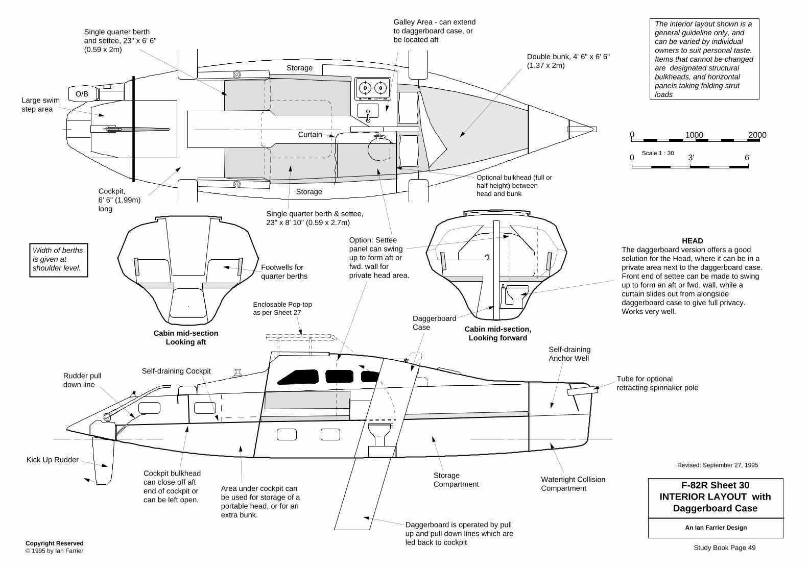
O/B
Copyright Reserved © 1995 by Ian Farrier
F-82R Sheet 30INTERIOR LAYOUT with
Daggerboard Case
An Ian Farrier Design
Watertight CollisionCompartment
Self-drainingAnchor Well
StorageCompartment
Self-draining Cockpit
Daggerboard is operated by pullup and pull down lines which areled back to cockpit
The interior layout shown is ageneral guideline only, andcan be varied by individualowners to suit personal taste.Items that cannot be changedare designated structuralbulkheads, and horizontalpanels taking folding strutloads
Scale 1 : 30
Revised: September 27, 1995Kick Up Rudder
Width of berthsis given atshoulder level.
Double bunk, 4' 6" x 6' 6"(1.37 x 2m)
Storage
Storage
Cockpit, 6' 6" (1.99m)long
Single quarter berth & settee,23" x 8' 10" (0.59 x 2.7m)
0 1000 2000
0 3' 6'
Single quarter berthand settee, 23" x 6' 6"(0.59 x 2m)
Rudder pulldown line
Tube for optionalretracting spinnaker pole
Cabin mid-section,Looking forward
Cabin mid-sectionLooking aft
Large swimstep area
Cockpit bulkheadcan close off aftend of cockpit orcan be left open.
HEADThe daggerboard version offers a goodsolution for the Head, where it can be in aprivate area next to the daggerboard case.Front end of settee can be made to swingup to form an aft or fwd. wall, while acurtain slides out from alongsidedaggerboard case to give full privacy.Works very well.
Curtain
Option: Setteepanel can swingup to form aft orfwd. wall forprivate head area.
Footwells forquarter berths
DaggerboardCase
Area under cockpit canbe used for storage of aportable head, or for anextra bunk.
Galley Area - can extendto daggerboard case, orbe located aft
Optional bulkhead (full orhalf height) betweenhead and bunk
Enclosable Pop-topas per Sheet 27
Study Book Page 49
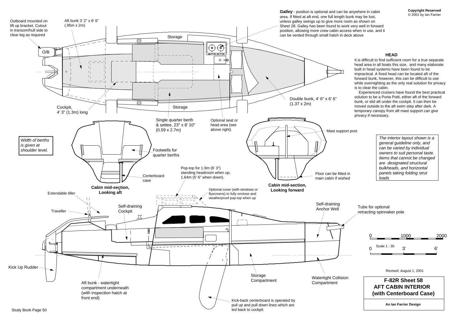
Copyright Reserved © 2001 by Ian Farrier
F-82R Sheet 58AFT CABIN INTERIOR
(with Centerboard Case)
An Ian Farrier Design
Watertight CollisionCompartment
Self-drainingAnchor Well
StorageCompartment
Self-drainingCockpit
The interior layout shown is ageneral guideline only, andcan be varied by individualowners to suit personal taste.Items that cannot be changedare designated structuralbulkheads, and horizontalpanels taking folding strutloads
Revised: August 1, 2001
Width of berthsis given atshoulder level.
Double bunk, 4' 6" x 6' 6"(1.37 x 2m)
Storage
Storage
Cockpit, 4' 3" (1.3m) long
Single quarter berth& settee, 23" x 8' 10"(0.59 x 2.7m)
Scale 1 : 30
0 1000 2000
0 3' 6'
Tube for optionalretracting spinnaker pole
Cabin mid-section,Looking forward
Cabin mid-section,Looking aft
Aft bunk - watertightcompartment underneath(with inspection hatch atfront end)
Footwells forquarter berths
HEADIt is difficult to find sufficient room for a true separatehead area in all boats this size, and many elaboratebuilt in head systems have been found to beimpractical. A fixed head can be located aft of theforward bunk, however, this can be difficult to usewhile overnighting as the only real solution for privacyis to clear the cabin. Experienced cruisers have found the best practicalsolution to be a Porta Potti, either aft of the forwardbunk, or slid aft under the cockpit. It can then bemoved outside to the aft swim step after dark. Atemporary canopy from aft mast support can giveprivacy if necessary.
Galley - position is optional and can be anywhere in cabinarea. If fitted at aft end, one full length bunk may be lost,unless galley swings up to give more room as shown onSheet 28. Galley has been found to work very well in forwardposition, allowing more crew cabin access when in use, and itcan be vented through small hatch in deck above
Centerboardcase
Mast support post
Floor can be fitted inmain cabin if wished
Kick-back centerboard is operated bypull up and pull down lines which areled back to cockpit
Optional seat orhead area (seeabove right).
Pop-top for 1.9m (6' 3")standing headroom when up,1.64m (5' 6" when down).
Optional cover (with windows orflyscreens) to fully enclose andweatherproof pop-top when up
Kick Up Rudder
Traveller
Aft bunk 3' 2" x 6' 6"(.95m x 2m)
Outboard mounted onlift up bracket. Cutoutin transom/hull side toclear leg as required
O/B
Extendable tiller
Study Book Page 50
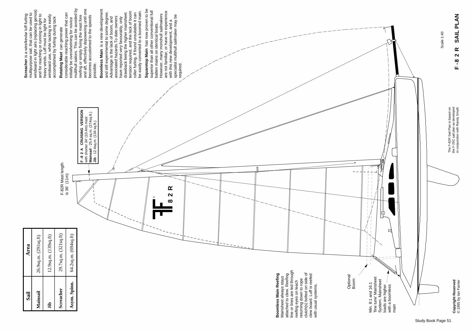
Co
pyr
igh
t R
eser
ved
©
199
5 by
Ian
Far
rier
82
R
F-8
2A
CR
UIS
ING
VE
RS
ION
with
sho
rter
34'
(10
.4m
) m
ast
Mai
nsa
il -
25.4
sq.
m. (
274s
q.ft.
)Ji
b -
12.
4sq.
m. (
134
sq.ft
.)
Opt
iona
lB
oom
:
F-8
2R
SA
IL P
LA
N
Sca
le 1
:40
Min
. 8:1
and
16:
1'fi
ne tu
ne' M
ains
heet
Sys
tem
. Mai
nshe
etlo
ads
are
high
erw
ith a
boo
mle
ssm
ain
Bo
om
less
Mai
n R
eefi
ng
Mai
nshe
et a
lway
s st
ays
atta
ched
to c
lew
. Ree
fing
line
or li
nes
are
led
thro
ugh
reef
ing
eyes
on
leac
hre
turn
ing
dow
n to
rop
ecl
utch
(s)
bolte
d on
sid
e of
clew
boa
rd. L
uff i
s re
efed
with
usu
al s
yste
ms.
Scr
each
er is
a w
ire/k
evla
r lu
ff fu
rling
mul
tipur
pose
sai
l, th
at c
an b
e us
ed to
win
dwar
d in
ligh
t airs
(re
plac
ing
geno
a)an
d fo
r re
achi
ng o
r ru
nnin
g in
ligh
t to
heav
y w
inds
. Luf
f mus
t be
tight
for
win
dwar
d us
e, w
hile
tack
ing
is e
asily
acco
mpl
ishe
d by
furli
ng d
urin
g ta
ck
Ro
tati
ng
Mas
t can
gen
erat
eco
nsid
erab
le r
each
ing
pow
er th
at c
anin
itial
ly b
e ov
erw
helm
ing
for
novi
cem
ultih
ull s
ailo
rs. T
his
can
be a
void
ed b
yre
efin
g or
sim
ply
fixin
g th
e m
ast f
ore
and
aft,
effe
ctiv
ely
depo
wer
ing
until
one
beco
mes
acc
usto
med
to th
e sp
eeds
poss
ible
.
Bo
om
less
Mai
n is
a n
ew d
evel
opm
ent
and
still
exp
erim
enta
l to
som
e de
gree
.A
dvan
tage
is th
e la
ck o
f boo
m, a
ndas
soci
ated
haz
ards
.To
date
ow
ners
have
rep
orte
d ve
ry fa
vour
ably
, onl
ydr
awba
ck b
eing
the
high
er m
ains
heet
tens
ion
requ
ired,
and
the
lack
of b
oom
rolle
r fu
rling
. If f
ound
uns
uita
ble
it ca
nbe
eas
ily c
onve
rted
to a
boo
med
mai
n.
Sq
uar
eto
p M
ain h
as n
ow p
rove
n to
be
supe
rior
than
all
othe
r co
nven
tiona
l ful
lba
tten
mai
ns o
n id
entic
al b
oats
.H
owev
er, m
any
mon
ohul
l sai
lmak
ers
are
not f
amili
ar, o
r ha
ve n
o ex
perie
nce
with
this
new
dev
elop
men
t, an
d a
spec
ialis
t mul
tihul
l sai
lmak
er m
ay b
ere
quire
d.
The
F-8
2R S
ail P
lan
is b
ased
on
the
F-2
5C s
ail p
lan
as d
evel
oped
in c
onju
nctio
n w
ith R
andy
Sm
yth
Study Book Page 51
®
Mai
nsai
l
2
6.9s
q.m
. (29
1sq.
ft)
Ji
b
12
.9sq
.m. (
139s
q.ft
)
Scre
ache
r
2
9.7s
q.m
. (32
1sq.
ft)
Asy
m. S
pinn
.
64
.2sq
.m. (
694s
q.ft
)
S
ail
Are
a
F-8
2R M
ast l
engt
his
36'
(11
m)
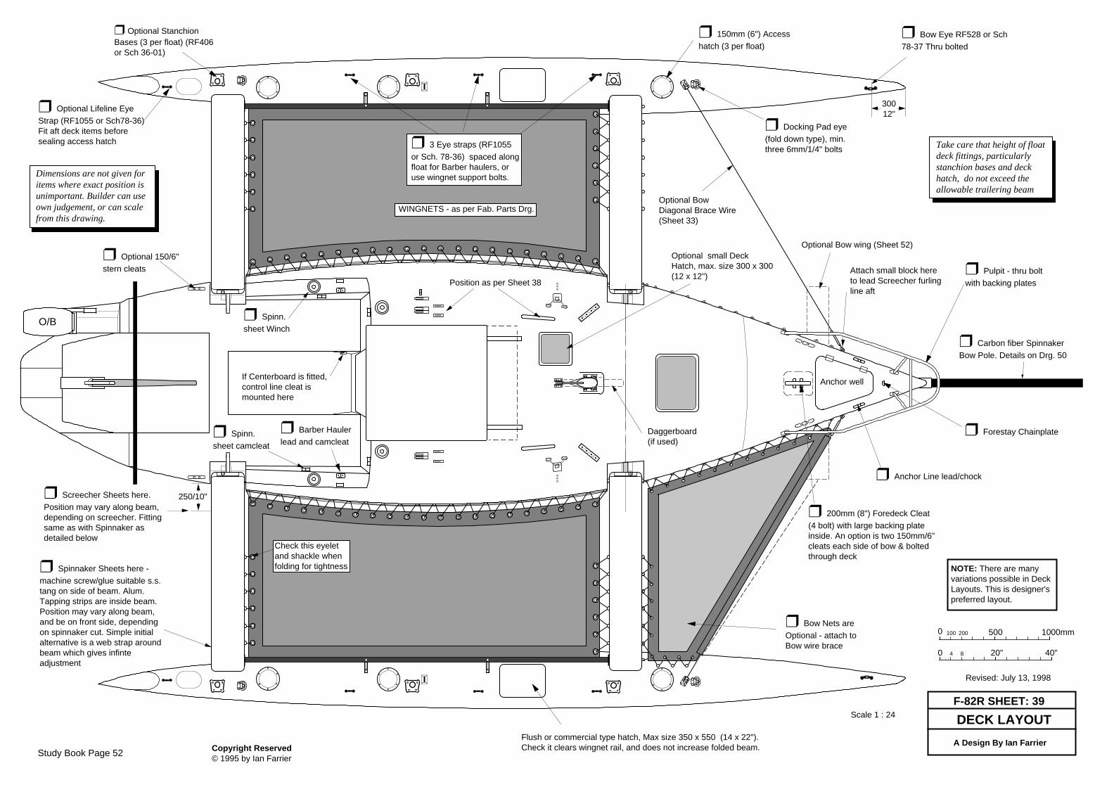
Revised: July 13, 1998
F-82R SHEET: 39
A Design By Ian Farrier
DECK LAYOUT
0 500 1000mm
0 40"20"4 8
100 200
NOTE: There are manyvariations possible in DeckLayouts. This is designer'spreferred layout.
Flush or commercial type hatch, Max size 350 x 550 (14 x 22").Check it clears wingnet rail, and does not increase folded beam.
❒ Bow Eye RF528 or Sch78-37 Thru bolted
❒ Optional StanchionBases (3 per float) (RF406or Sch 36-01)
❒ 150mm (6") Accesshatch (3 per float)
❒ Optional Lifeline EyeStrap (RF1055 or Sch78-36)Fit aft deck items beforesealing access hatch
30012"
❒ 200mm (8") Foredeck Cleat(4 bolt) with large backing plateinside. An option is two 150mm/6"cleats each side of bow & boltedthrough deck
❒ Bow Nets areOptional - attach toBow wire brace
Copyright Reserved © 1995 by Ian Farrier
Scale 1 : 24
Take care that height of floatdeck fittings, particularlystanchion bases and deckhatch, do not exceed theallowable trailering beam
❒ Pulpit - thru boltwith backing plates
❒ Anchor Line lead/chock
❒ Barber Haulerlead and camcleat
Dimensions are not given foritems where exact position isunimportant. Builder can useown judgement, or can scalefrom this drawing.
Hatch
❒ Carbon fiber SpinnakerBow Pole. Details on Drg. 50
❒ Forestay Chainplate
❒ Spinnaker Sheets here -machine screw/glue suitable s.s.tang on side of beam. Alum.Tapping strips are inside beam.Position may vary along beam,and be on front side, dependingon spinnaker cut. Simple initialalternative is a web strap aroundbeam which gives infinteadjustment
Optional BowDiagonal Brace Wire(Sheet 33)
Anchor well
❒ Spinn.sheet Winch
❒ Spinn.sheet camcleat
If Centerboard is fitted,control line cleat ismounted here
Daggerboard(if used)
Check this eyeletand shackle whenfolding for tightness
❒ Screecher Sheets here.Position may vary along beam,depending on screecher. Fittingsame as with Spinnaker asdetailed below
Attach small block hereto lead Screecher furlingline aft
❒ Optional 150/6"stern cleats
Optional small DeckHatch, max. size 300 x 300(12 x 12")
Position as per Sheet 38
Optional Bow wing (Sheet 52)
WINGNETS - as per Fab. Parts Drg.
❒ 3 Eye straps (RF1055or Sch. 78-36) spaced alongfloat for Barber haulers, oruse wingnet support bolts.
O/B
❒ Docking Pad eye(fold down type), min.three 6mm/1/4" bolts
250/10"
Study Book Page 52
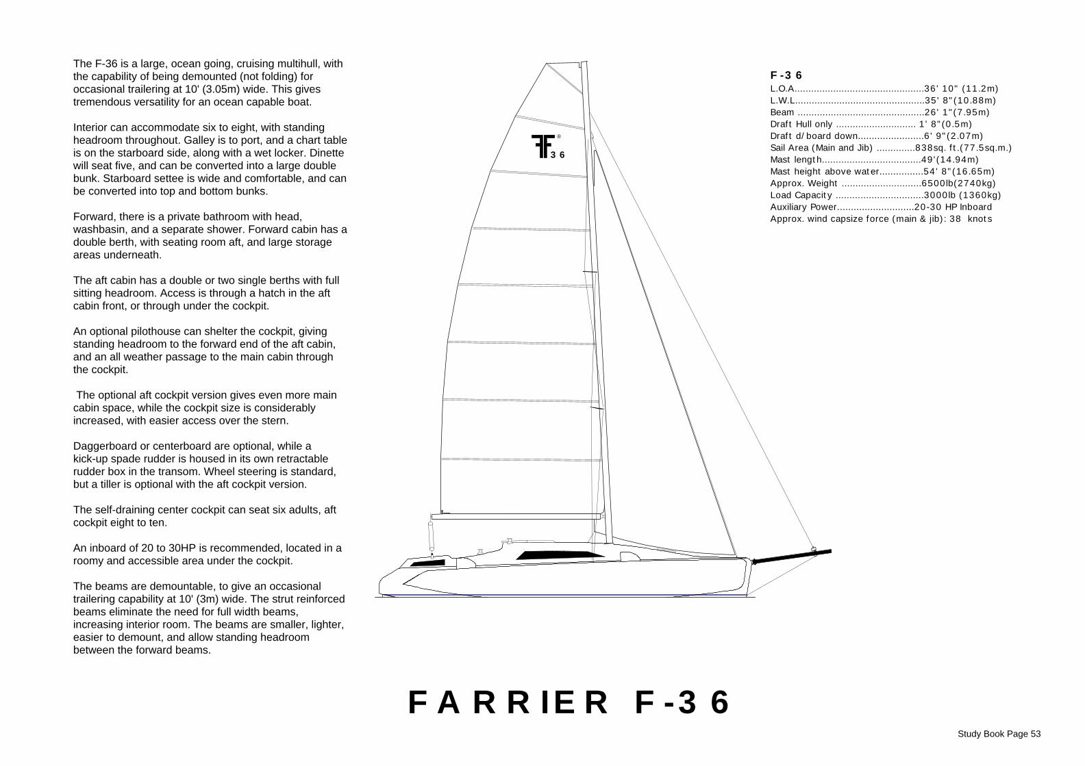
Study Book Page 53
F-36 L.O.A...............................................36' 10" (11.2m) L.W.L...............................................35' 8"(10.88m) Beam ..............................................26' 1"(7.95m) Draft Hull only ............................. 1' 8"(0.5m) Draft d/board down........................6' 9"(2.07m)Sail Area (Main and Jib) ..............838sq. ft.(77.5sq.m.)Mast length....................................49'(14.94m)Mast height above water................54' 8"(16.65m)Approx. Weight .............................6500lb(2740kg) Load Capacity ................................3000lb (1360kg)Auxiliary Power............................20-30 HP InboardApprox. wind capsize force (main & jib): 38 knots
FARRIER F-36
36
®
The F-36 is a large, ocean going, cruising multihull, withthe capability of being demounted (not folding) foroccasional trailering at 10' (3.05m) wide. This givestremendous versatility for an ocean capable boat.
Interior can accommodate six to eight, with standingheadroom throughout. Galley is to port, and a chart tableis on the starboard side, along with a wet locker. Dinettewill seat five, and can be converted into a large doublebunk. Starboard settee is wide and comfortable, and canbe converted into top and bottom bunks.
Forward, there is a private bathroom with head,washbasin, and a separate shower. Forward cabin has adouble berth, with seating room aft, and large storageareas underneath.
The aft cabin has a double or two single berths with fullsitting headroom. Access is through a hatch in the aftcabin front, or through under the cockpit.
An optional pilothouse can shelter the cockpit, givingstanding headroom to the forward end of the aft cabin,and an all weather passage to the main cabin throughthe cockpit.
The optional aft cockpit version gives even more maincabin space, while the cockpit size is considerablyincreased, with easier access over the stern.
Daggerboard or centerboard are optional, while akick-up spade rudder is housed in its own retractablerudder box in the transom. Wheel steering is standard,but a tiller is optional with the aft cockpit version.
The self-draining center cockpit can seat six adults, aftcockpit eight to ten.
An inboard of 20 to 30HP is recommended, located in aroomy and accessible area under the cockpit.
The beams are demountable, to give an occasionaltrailering capability at 10' (3m) wide. The strut reinforcedbeams eliminate the need for full width beams,increasing interior room. The beams are smaller, lighter,easier to demount, and allow standing headroombetween the forward beams.
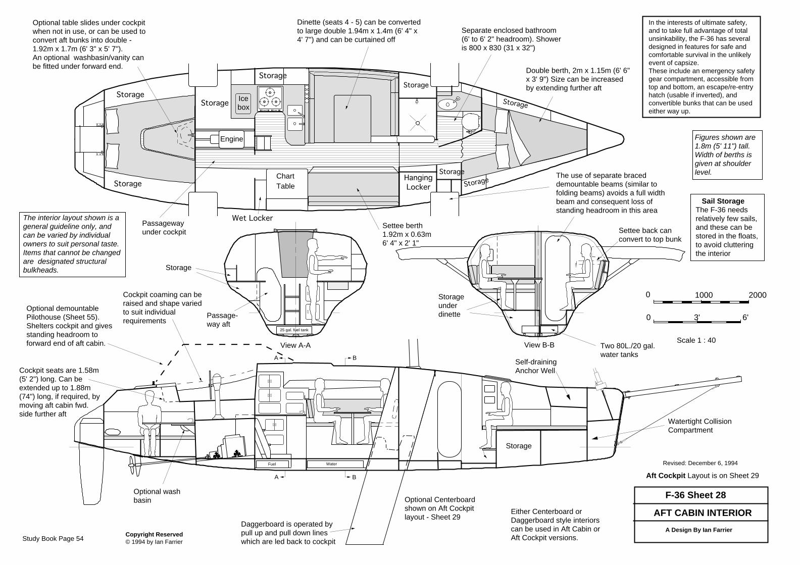
Copyright Reserved © 1994 by Ian Farrier
AFT CABIN INTERIOR
The interior layout shown is ageneral guideline only, andcan be varied by individualowners to suit personal taste.Items that cannot be changedare designated structuralbulkheads.
Revised: December 6, 1994
Aft Cockpit Layout is on Sheet 29
Figures shown are1.8m (5' 11") tall.Width of berths isgiven at shoulderlevel.
F-36 Sheet 28
A Design By Ian Farrier
Scale 1 : 40
0 1000 2000
0 3' 6'
Watertight CollisionCompartment
Self-drainingAnchor Well
Daggerboard is operated bypull up and pull down lineswhich are led back to cockpit
Optional table slides under cockpitwhen not in use, or can be used toconvert aft bunks into double -1.92m x 1.7m (6' 3" x 5' 7"). An optional washbasin/vanity canbe fitted under forward end.
Separate enclosed bathroom(6' to 6' 2" headroom). Showeris 800 x 830 (31 x 32")
ChartTable
Passagewayunder cockpit
Icebox
Engine
Dinette (seats 4 - 5) can be convertedto large double 1.94m x 1.4m (6' 4" x4' 7") and can be curtained off
HangingLocker
Wet Locker
Storage
StorageStorage
Storage
Storage
Optional Centerboardshown on Aft Cockpitlayout - Sheet 29
Storage
Storage
Fuel Water
Two 80L./20 gal.water tanks
Storageunderdinette
Settee back canconvert to top bunk
25 gal. fuel tank
A
A
B
B
View A-A View B-B
Passage-way aft
Storage
Double berth, 2m x 1.15m (6' 6"x 3' 9") Size can be increasedby extending further aft
Settee berth1.92m x 0.63m6' 4" x 2' 1"
Storage
Storage
Optional demountablePilothouse (Sheet 55).Shelters cockpit and givesstanding headroom toforward end of aft cabin.
Either Centerboard orDaggerboard style interiorscan be used in Aft Cabin orAft Cockpit versions.
The use of separate braceddemountable beams (similar tofolding beams) avoids a full widthbeam and consequent loss ofstanding headroom in this area
Sail StorageThe F-36 needsrelatively few sails,and these can bestored in the floats,to avoid clutteringthe interior
Cockpit coaming can beraised and shape variedto suit individualrequirements
Cockpit seats are 1.58m(5' 2") long. Can beextended up to 1.88m(74") long, if required, bymoving aft cabin fwd.side further aft
Optional washbasin
In the interests of ultimate safety,and to take full advantage of totalunsinkability, the F-36 has severaldesigned in features for safe andcomfortable survival in the unlikelyevent of capsize. These include an emergency safetygear compartment, accessible fromtop and bottom, an escape/re-entryhatch (usable if inverted), andconvertible bunks that can be usedeither way up.
Study Book Page 54
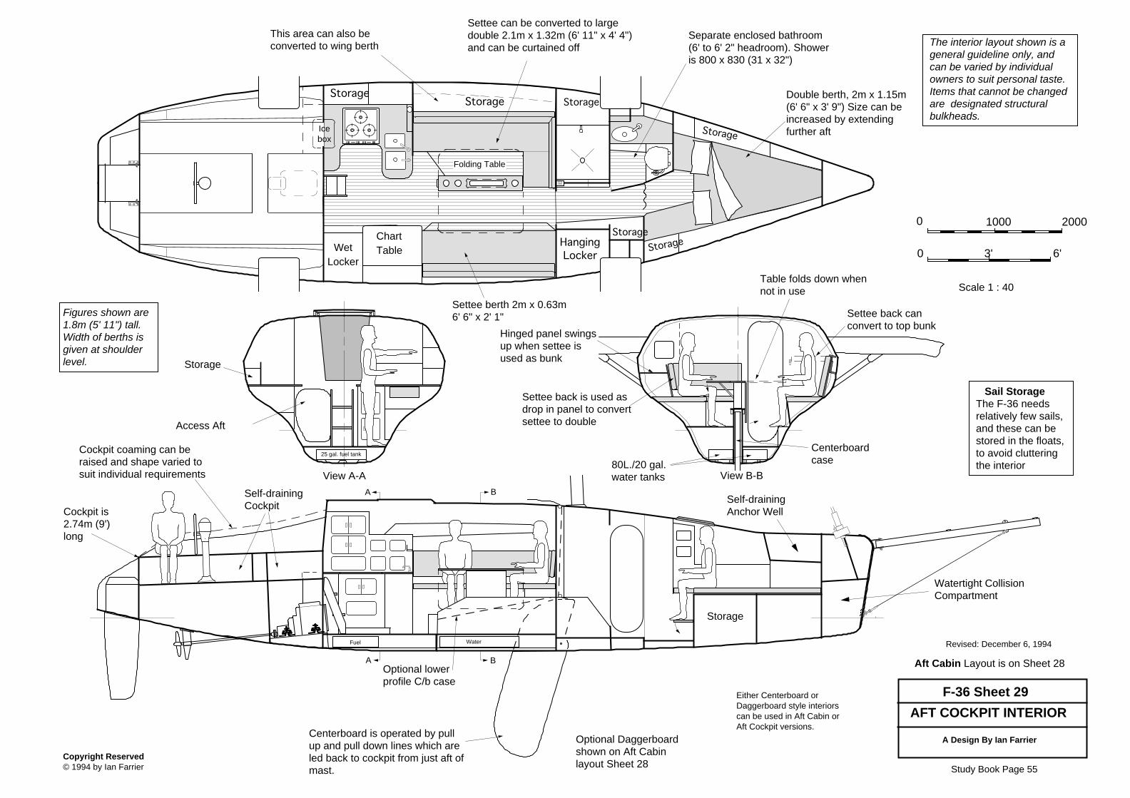
Copyright Reserved © 1994 by Ian Farrier
AFT COCKPIT INTERIOR
The interior layout shown is ageneral guideline only, andcan be varied by individualowners to suit personal taste.Items that cannot be changedare designated structuralbulkheads.
Revised: December 6, 1994
Aft Cabin Layout is on Sheet 28
Figures shown are1.8m (5' 11") tall.Width of berths isgiven at shoulderlevel.
F-36 Sheet 29
A Design By Ian Farrier
Scale 1 : 40
0 1000 2000
0 3' 6'
Watertight CollisionCompartment
Self-drainingAnchor Well
Self-drainingCockpit
Centerboard is operated by pullup and pull down lines which areled back to cockpit from just aft ofmast.
ChartTable
Settee can be converted to largedouble 2.1m x 1.32m (6' 11" x 4' 4")and can be curtained off
HangingLocker
WetLocker
Storage
Storage
Optional Daggerboardshown on Aft Cabinlayout Sheet 28
Storage
Storage
Fuel
80L./20 gal.water tanks
Settee back canconvert to top bunk
25 gal. fuel tank
A
A
B
B
View A-A View B-B
Centerboardcase
Access Aft
Storage
Settee berth 2m x 0.63m6' 6" x 2' 1"
Storage
Storage
Either Centerboard orDaggerboard style interiorscan be used in Aft Cabin orAft Cockpit versions.
Storage
Hinged panel swingsup when settee isused as bunk
Settee back is used asdrop in panel to convertsettee to double
This area can also beconverted to wing berth
Table folds down whennot in use
Icebox
Separate enclosed bathroom(6' to 6' 2" headroom). Showeris 800 x 830 (31 x 32")
Sail StorageThe F-36 needsrelatively few sails,and these can bestored in the floats,to avoid clutteringthe interior
Cockpit coaming can beraised and shape varied tosuit individual requirements
Cockpit is2.74m (9')long
Double berth, 2m x 1.15m(6' 6" x 3' 9") Size can beincreased by extendingfurther aft
Folding Table
Optional lowerprofile C/b case
Water
Study Book Page 55
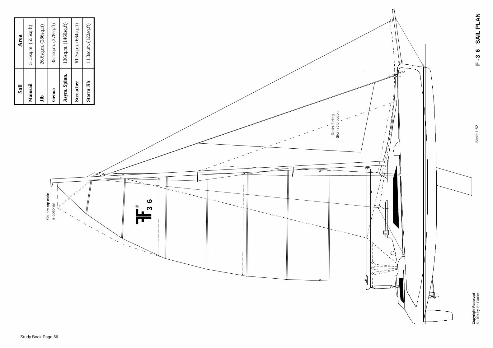
Co
pyr
igh
t R
eser
ved
©
199
4 by
Ian
Far
rier
Sca
le 1
:52
F-3
6 S
AIL
PL
AN
Study Book Page 56
Mai
nsai
l
5
1.5s
q.m
. (55
5sq.
ft)
Ji
b
26
.6sq
.m. (
286s
q.ft
)
Gen
oa
3
5.1s
q.m
. (37
8sq.
ft)
Asy
m. S
pinn
.
13
6sq.
m. (
1460
sq.f
t)
Scre
ache
r
6
1.7s
q.m
. (66
4sq.
ft)
Stor
m J
ib
1
1.3s
q.m
. (12
2sq.
ft)
S
ail
Are
a
Squ
are
top
mai
nis
opt
iona
l
® 36
Rol
ler
furli
ngS
torm
Jib
opt
ion
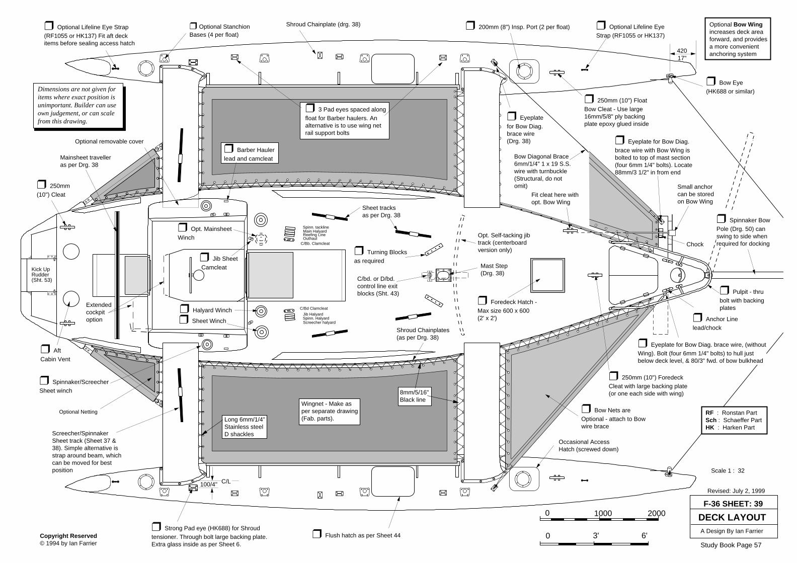
Optional removable cover
Copyright Reserved © 1994 by Ian Farrier
Scale 1 : 32
❒ Bow Eye(HK688 or similar)
❒ 200mm (8") Insp. Port (2 per float)❒ Optional Lifeline Eye Strap(RF1055 or HK137) Fit aft deckitems before sealing access hatch
Revised: July 2, 1999
Shroud Chainplate (drg. 38)
F-36 SHEET: 39
A Design By Ian Farrier
DECK LAYOUT
❒ Foredeck Hatch -Max size 600 x 600(2' x 2')
❒ Bow Nets areOptional - attach to Bowwire brace
❒ Strong Pad eye (HK688) for Shroudtensioner. Through bolt large backing plate.Extra glass inside as per Sheet 6.
❒ Optional StanchionBases (4 per float)
❒ 250mm (10") FloatBow Cleat - Use large16mm/5/8" ply backingplate epoxy glued inside
Sheet tracksas per Drg. 38
❒ Turning Blocksas required
Mast Step(Drg. 38)
❒ Sheet Winch
C/Bd Clamcleat
Jib HalyardSpinn. Halyard
Main Halyard
C/Bb. Clamcleat
❒ Jib Sheet Camcleat
❒ Spinnaker/ScreecherSheet winch
❒ 250mm(10") Cleat
❒ AftCabin Vent
Mainsheet travelleras per Drg. 38
Dimensions are not given foritems where exact position isunimportant. Builder can useown judgement, or can scalefrom this drawing.
42017"
❒ Flush hatch as per Sheet 44
❒ Eyeplatefor Bow Diag.brace wire(Drg. 38)
Shroud Chainplates(as per Drg. 38)
❒ 250mm (10") ForedeckCleat with large backing plate(or one each side with wing)
Spinn. tackline
❒ 3 Pad eyes spaced alongfloat for Barber haulers. Analternative is to use wing netrail support bolts
❒ Barber Haulerlead and camcleat Bow Diagonal Brace
6mm/1/4" 1 x 19 S.S.wire with turnbuckle(Structural, do notomit)
Opt. Self-tacking jibtrack (centerboardversion only)
Screecher halyard
❒ Halyard Winch
❒ Opt. MainsheetWinch
RF : Ronstan PartSch : Schaeffer PartHK : Harken Part
0 1000 2000
0 3' 6'
Occasional AccessHatch (screwed down)
Screecher/SpinnakerSheet track (Sheet 37 &38). Simple alternative isstrap around beam, whichcan be moved for bestposition
Extendedcockpitoption
Fit cleat here withopt. Bow Wing
❒ Anchor Linelead/chock
❒ Pulpit - thrubolt with backingplates
❒ Eyeplate for Bow Diag.brace wire with Bow Wing isbolted to top of mast section(four 6mm 1/4" bolts). Locate88mm/3 1/2" in from end
Small anchorcan be storedon Bow Wing
❒ Eyeplate for Bow Diag. brace wire, (withoutWing). Bolt (four 6mm 1/4" bolts) to hull justbelow deck level, & 80/3" fwd. of bow bulkhead
100/4" C/L
❒ Optional Lifeline EyeStrap (RF1055 or HK137)
Chock
Reefing LineOuthaul
Optional Bow Wingincreases deck areaforward, and providesa more convenientanchoring system
❒ Spinnaker BowPole (Drg. 50) canswing to side whenrequired for docking
Optional Netting
Wingnet - Make asper separate drawing(Fab. parts).
8mm/5/16"Black line
Long 6mm/1/4"Stainless steelD shackles
52020"
Kick UpRudder(Sht. 53) C/bd. or D/bd.
control line exitblocks (Sht. 43)
Study Book Page 57
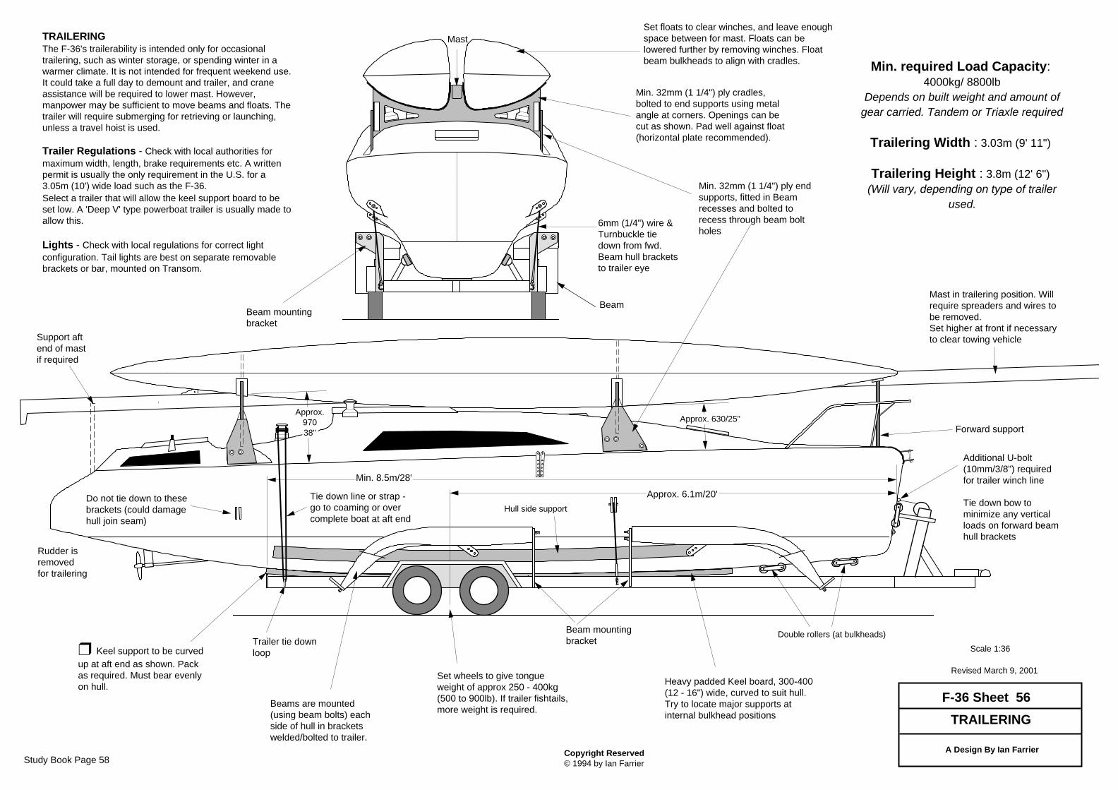
Copyright Reserved © 1994 by Ian Farrier
TRAILERING
A Design By Ian Farrier
Scale 1:36
Revised March 9, 2001
F-36 Sheet 56
TRAILERINGThe F-36's trailerability is intended only for occasionaltrailering, such as winter storage, or spending winter in awarmer climate. It is not intended for frequent weekend use.It could take a full day to demount and trailer, and craneassistance will be required to lower mast. However,manpower may be sufficient to move beams and floats. Thetrailer will require submerging for retrieving or launching,unless a travel hoist is used.
Trailer Regulations - Check with local authorities formaximum width, length, brake requirements etc. A writtenpermit is usually the only requirement in the U.S. for a3.05m (10') wide load such as the F-36.Select a trailer that will allow the keel support board to beset low. A 'Deep V' type powerboat trailer is usually made toallow this.
Lights - Check with local regulations for correct lightconfiguration. Tail lights are best on separate removablebrackets or bar, mounted on Transom.
Support aftend of mastif required
Rudder isremovedfor trailering
Tie down line or strap -go to coaming or overcomplete boat at aft end
Trailer tie downloop
Mast in trailering position. Willrequire spreaders and wires tobe removed. Set higher at front if necessaryto clear towing vehicle
Min. required Load Capacity: 4000kg/ 8800lb
Depends on built weight and amount of
gear carried. Tandem or Triaxle required
Trailering Width : 3.03m (9' 11")
Trailering Height : 3.8m (12' 6") (Will vary, depending on type of trailer
used.
❒ Keel support to be curvedup at aft end as shown. Packas required. Must bear evenlyon hull.
Forward support
Min. 32mm (1 1/4") ply endsupports, fitted in Beamrecesses and bolted torecess through beam boltholes
Set floats to clear winches, and leave enoughspace between for mast. Floats can belowered further by removing winches. Floatbeam bulkheads to align with cradles.
Min. 32mm (1 1/4") ply cradles,bolted to end supports using metalangle at corners. Openings can becut as shown. Pad well against float(horizontal plate recommended).
Approx.97038"
Approx. 630/25"
Hull side support
Heavy padded Keel board, 300-400(12 - 16") wide, curved to suit hull.Try to locate major supports atinternal bulkhead positions
Double rollers (at bulkheads)
6mm (1/4") wire &Turnbuckle tiedown from fwd.Beam hull bracketsto trailer eye
Beam mountingbracket
Approx. 6.1m/20'
Set wheels to give tongueweight of approx 250 - 400kg(500 to 900lb). If trailer fishtails,more weight is required.
Additional U-bolt(10mm/3/8") requiredfor trailer winch line
Tie down bow tominimize any verticalloads on forward beamhull brackets
Min. 8.5m/28'
Beams are mounted(using beam bolts) eachside of hull in bracketswelded/bolted to trailer.
Beam mountingbracket
Beam
Mast
Do not tie down to thesebrackets (could damagehull join seam)
Study Book Page 58
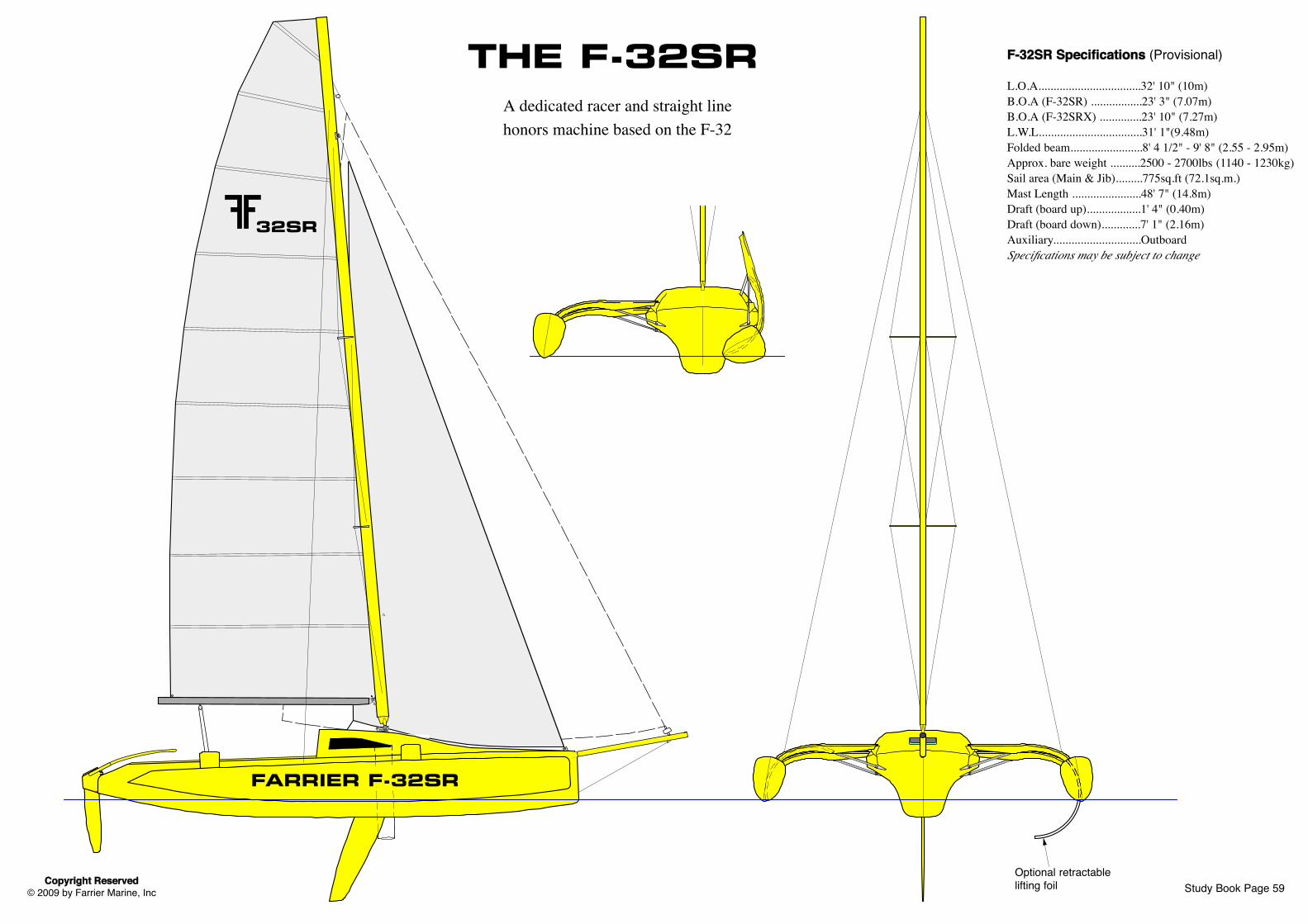
2
32SR
Study Book Page 59Copyright Reserved© 2009 by Farrier Marine, Inc
THE F-32SRA dedicated racer and straight linehonors machine based on the F-32
F-32SR Specifications (Provisional)
L.O.A..................................32' 10" (10m)B.O.A (F-32SR) .................23' 3" (7.07m)B.O.A (F-32SRX) ..............23' 10" (7.27m)L.W.L..................................31' 1"(9.48m)Folded beam........................8' 4 1/2" - 9' 8" (2.55 - 2.95m)Approx. bare weight ..........2500 - 2700lbs (1140 - 1230kg)Sail area (Main & Jib).........775sq.ft (72.1sq.m.)Mast Length .......................48' 7" (14.8m)Draft (board up)..................1' 4" (0.40m)Draft (board down).............7' 1" (2.16m)Auxiliary.............................OutboardSpecifications may be subject to change
Optional retractable lifting foil
FARRIER F-32SR
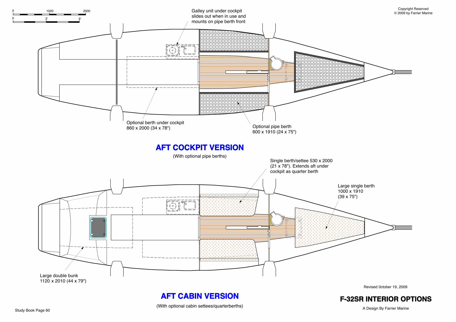
Large double bunk 1120 x 2010 (44 x 79")
AFT CABIN VERSION
Large single berth 1000 x 1910 (39 x 75")
Galley unit under cockpit slides out when in use and mounts on pipe berth front
Optional pipe berth600 x 1910 (24 x 75")
AFT COCKPIT VERSION(With optional pipe berths)
(With optional cabin settees/quarterberths)
Optional berth under cockpit860 x 2000 (34 x 78")
F-32SR INTERIOR OPTIONSA Design By Farrier Marine
Revised 0ctober 19, 2009
Copyright Reserved© 2009 by Farrier Marine
Single berth/settee 530 x 2000 (21 x 78"). Extends aft under cockpit as quarter berth
Study Book Page 60
0 3' 6'
0 1000 2000