01!/2 !+,&!! 3)4&!#(4&$+)/#!5/6/+! 35-78 !...
TRANSCRIPT

Increasing the Autonomy of the Pipe Inspection Robot PIRATE
G.A. (Gisela) Garza Morales
MSc Report
C eProf.dr.ir. S. Stramigioli
Dr.ir. E.C. Dertien Dr.ir. J.F. Broenink
Dr.ir. G. van Oort
August 2016
036RAM2016 Robotics and Mechatronics
EE-Math-CS University of Twente
P.O. Box 217 7500 AE Enschede
The Netherlands

ii Increasing the Autonomy of the Pipe Inspection Robot PIRATE
Summary
The Pipe Inspection Robot for AuTonomous Exploration, or for short PIRATE, is an inspectionrobot for gas pipes. It aims to determine the location of a leak more accurately so that workersknow where they need to dig a hole and thereby making the digging more precise (and cheaper).Another advantage that might be offered by such robot, is that not only leaks can be detected,but also the quality of the network can be inspected and weak spots can be detected and berepaired even before gas leakage might occur. Currently the efforts put into the robot havebeen focused on the mechanical, electronics, communication and vision areas, nonetheless,the movement is still dependent on manual operation by a skillful inspector. This can providea safe inspection, however, it can be labor intensive (costly) and time consuming. Ideally andin order to be usable in a commercial (industrial) environment a certain level of autonomy isrequired.
The present thesis aims at increasing the current level of autonomy for the PIRATE by designingand implementing autonomous behaviors. At first an analysis of the possible layered controlsoftware structure is done. From this, the scope of the thesis is limited to the Sequential layer(control of small/simple sequences). Based on this, the goal becomes to design and implementthese simple sequences (Partially Autonomous Behaviors - PABs) in a modular and scalablemanner, which can also be integrated with the current manual control. To demonstrate thepotential of the design a simple mission that combines various PABs (namely clamp straight,drive and home) has been developed.
The design part of the project includes the development of the software framework where thesimple autonomous sequences can be constructed. This is done using the object oriented ap-proach, where different classes are developed according to specific functionality. The basicfunctionalities that are covered in the design are: communicating with the user interface, trans-lating its commands and send them as robot instructions, creating a centralized structure forcoherent message sharing, developing and managing operation modes (manual and partiallyautonomous), designing and implementing the Partially Autonomous Behavior (PAB) routinesand receiving the current robot state, among others.
For the implementation of the software framework the Robot Operating System environmentis chosen, because it has been previously used for the implementation of the feedback statereception and a visual interface, as well as for the wide variety of packages for robot implemen-tation it offers. During the development, the transition conditions (guards) were experimen-tally defined. In the final experiments, these conditions and the sequences are tested coveringthree different situations: clamping when no re-orientation is needed, clamping when slight re-orientation is required and clamping starting from a lying position (complete re-orientation).
The results show that, in each of these situations, the proposed sequence and transition con-ditions effectively clamp the robot in the desired orientation. Apart from these experiments,the simple mission was tested and it successfully shows that different PAB classes could becombined to create more complex sequences or plans. It was possible to see the importanceof the software control layers approach, which greatly facilitated the design process and ac-complished modularity and re-usability, especially in the pattern followed to design the PABclasses, which can be reused and adjusted for future PABs. Some general recommendationsare to include, apart from the angle feedback, torque measurement in the transition conditionsto increase robustness. Another strong suggestion is to improve the wiring and in general theprototype material to reduce fragility. Overall the present study successfully presents a suitablesoftware framework for further development of other PABs in the Sequential layer, as well aspotential for creating more complex missions by integrating them.
Gisela Anaid Garza Morales University of Twente

iii
PrefaceTo my lovely parents, Rosario and Ernesto, without whom this would not have been possible.Thank you for always encouraging me, believing in me and above all for the wonderful life thatyou gave me and all the opportunities I had. To my little brother, who has always been a supportin my life. He is true to himself as I want to be. To the love of my life, Armando, thank you foreverything, for being in my life, for inspiring me everyday, for being cheerful and calming meduring my stress days (always). This marks the end of one of our adventures. Hopefully manymore will come.
I would like to dedicate this thesis specially to my aunt Mague (RIP) and my grandfatherErnesto(RIP). God has called both of you during these two years that I was away. I know thatyou were and still are watching over me and I hope this makes you proud. I will forever missyou.
To the rest of my lovely family who has always supported me, specially my cousins Greta, Edgar,Eduardo, Caty, Juan Carlos, Tommy, Male, Beto, Luis, Roberto, Daniel, Paola, to my aunts anduncle Maria Elena, Alicia, Tomas, Norma, Sandra, Chiquis, Lalo and Sergio. Thanks to mynephews Pepe, Erik, Emilio and Esteban and to baby Dania, who I haven’t met yet. You guyswere the first that showed me what loving something so innocent and perfect was about.
Thanks to all the great people that I have met through these wonderful (and sometimes painful)two years: Hengameh, Mohamed, Evyatar, Giuseppe, Nelson, Charalambos, Abishek, Helena,Carlos, Shamel, Adel, Samer, Vivian, and many more. Also to the wonderful people that I metway before and that are also here living their dutch adventures: Cynthia and Cobos, thanksfor your support, your advice and joining my adventures. To my best group of friends: Vero,Johana, Joyce, Loren, Marce, Chaba, Franky, Borre, Chihuis, Axel, Cesar, Moros. Thanks to all ofyou for your great support and friendship.
From RAM, special thanks to Mark, I really appreciate all the time you spent explaining me andall your patience, without you this wouldn’t have been possible. To Douwe, for introducingme to MakerSpace, for challenging me and for his great advice in a time that I really neededit. To Zhou, for all your great advice and ideas. To my supervisor Edwin, for all his support,inspiration and guidance. To Jan, for pointing me to the right direction, your overall supportand apart from this project, all your teaching. To Gijs, for helping me when I needed the mostduring this project, thanks for your support. To Jolanda, for calming me down when I went tosee her, I really needed to hear that it was going to be okay.
I am probably missing more people in the list, but in general thanks to all the people who inone way or another have touched my life and stayed with me. I promise I won’t let you down.
Gisela A. Garza MoralesEnschede, August 2016
Robotics and Mechatronics Gisela Anaid Garza Morales

iv Increasing the Autonomy of the Pipe Inspection Robot PIRATE
Gisela Anaid Garza Morales University of Twente
v
Contents
1 Introduction 1
1.1 Context . . . . . . . . . . . . . . . . . . . . . . . . . . . . . . . . . . . . . . . . . . . . 1
1.2 Problem statement . . . . . . . . . . . . . . . . . . . . . . . . . . . . . . . . . . . . . 1
1.3 Goals . . . . . . . . . . . . . . . . . . . . . . . . . . . . . . . . . . . . . . . . . . . . . 2
1.4 Approach . . . . . . . . . . . . . . . . . . . . . . . . . . . . . . . . . . . . . . . . . . . 2
1.5 Organization of the report . . . . . . . . . . . . . . . . . . . . . . . . . . . . . . . . . 3
2 Background 4
2.1 Robot Operating System (ROS) . . . . . . . . . . . . . . . . . . . . . . . . . . . . . . 4
2.2 UML basics . . . . . . . . . . . . . . . . . . . . . . . . . . . . . . . . . . . . . . . . . 5
2.3 System Control Architectures . . . . . . . . . . . . . . . . . . . . . . . . . . . . . . . 6
2.4 The PIRATE robot . . . . . . . . . . . . . . . . . . . . . . . . . . . . . . . . . . . . . . 9
3 Analysis 16
3.1 Current system control architecture . . . . . . . . . . . . . . . . . . . . . . . . . . . 16
3.2 Analysis of a layered software architecture for the PIRATE . . . . . . . . . . . . . . 16
3.3 Considerations for moving towards the Sequential control layer . . . . . . . . . . 18
3.4 Requirements . . . . . . . . . . . . . . . . . . . . . . . . . . . . . . . . . . . . . . . . 19
3.5 Design choices . . . . . . . . . . . . . . . . . . . . . . . . . . . . . . . . . . . . . . . 20
3.6 Project scope and limitations . . . . . . . . . . . . . . . . . . . . . . . . . . . . . . . 20
4 Software Framework Design 21
4.1 General framework design . . . . . . . . . . . . . . . . . . . . . . . . . . . . . . . . . 21
4.2 Setpoint class . . . . . . . . . . . . . . . . . . . . . . . . . . . . . . . . . . . . . . . . 23
4.3 Control class . . . . . . . . . . . . . . . . . . . . . . . . . . . . . . . . . . . . . . . . . 24
4.4 Limit class . . . . . . . . . . . . . . . . . . . . . . . . . . . . . . . . . . . . . . . . . . 24
4.5 Pirate Manager class . . . . . . . . . . . . . . . . . . . . . . . . . . . . . . . . . . . . 25
4.6 Mapper Class . . . . . . . . . . . . . . . . . . . . . . . . . . . . . . . . . . . . . . . . 25
4.7 Pirate Server class . . . . . . . . . . . . . . . . . . . . . . . . . . . . . . . . . . . . . . 26
4.8 Interfaces . . . . . . . . . . . . . . . . . . . . . . . . . . . . . . . . . . . . . . . . . . . 35
5 Implementation 38
5.1 Serial communication between Arduino Mega and ROS . . . . . . . . . . . . . . . 38
5.2 Actionlib from ROS . . . . . . . . . . . . . . . . . . . . . . . . . . . . . . . . . . . . . 39
5.3 ROS Services . . . . . . . . . . . . . . . . . . . . . . . . . . . . . . . . . . . . . . . . . 39
5.4 User interface drivers . . . . . . . . . . . . . . . . . . . . . . . . . . . . . . . . . . . . 40
5.5 Use Cases . . . . . . . . . . . . . . . . . . . . . . . . . . . . . . . . . . . . . . . . . . . 40
Robotics and Mechatronics Gisela Anaid Garza Morales

vi Increasing the Autonomy of the Pipe Inspection Robot PIRATE
5.6 Generalized ROS software implementation . . . . . . . . . . . . . . . . . . . . . . . 44
5.7 Mapper class implementation . . . . . . . . . . . . . . . . . . . . . . . . . . . . . . 46
5.8 Pirate Server class implementation . . . . . . . . . . . . . . . . . . . . . . . . . . . 47
5.9 Motion Primitives class implementation . . . . . . . . . . . . . . . . . . . . . . . . 48
5.10 Clamp Straight class implementation . . . . . . . . . . . . . . . . . . . . . . . . . . 49
5.11 Pirate State implementation . . . . . . . . . . . . . . . . . . . . . . . . . . . . . . . . 51
5.12 Simple test mission implementation . . . . . . . . . . . . . . . . . . . . . . . . . . . 52
6 Results 53
6.1 Tests . . . . . . . . . . . . . . . . . . . . . . . . . . . . . . . . . . . . . . . . . . . . . . 53
6.2 Simple clamp straight in 90mm pipe . . . . . . . . . . . . . . . . . . . . . . . . . . . 53
6.3 Nominal re-adjust clamp straight in 90mm pipe . . . . . . . . . . . . . . . . . . . . 55
6.4 Non-nominal clamp straight in 90mm pipe . . . . . . . . . . . . . . . . . . . . . . . 57
6.5 Simple test mission in 90mm pipe . . . . . . . . . . . . . . . . . . . . . . . . . . . . 60
6.6 General guards evaluation . . . . . . . . . . . . . . . . . . . . . . . . . . . . . . . . . 62
7 Conclusions and Recommendations 63
7.1 Conclusions . . . . . . . . . . . . . . . . . . . . . . . . . . . . . . . . . . . . . . . . . 63
7.2 Recommendations . . . . . . . . . . . . . . . . . . . . . . . . . . . . . . . . . . . . . 64
A Appendix: Designed classes 67
B Appendix: Additional mapping information 70
B.1 Pirate State array mapping per PICO Board . . . . . . . . . . . . . . . . . . . . . . . 70
C Appendix: Feedback screen 71
C.1 Mapper class implementation . . . . . . . . . . . . . . . . . . . . . . . . . . . . . . 71
C.2 Pirate Server class implementation . . . . . . . . . . . . . . . . . . . . . . . . . . . 71
C.3 Motion Primitives class implementation . . . . . . . . . . . . . . . . . . . . . . . . 72
C.4 Clamp straight class implementation . . . . . . . . . . . . . . . . . . . . . . . . . . 72
D Appendix: Transition conditions and Results 74
D.1 Transition conditions for Clamp Straight state machine . . . . . . . . . . . . . . . 74
D.2 Additional graphs for nominal re-adjust clamp straight in 110mm pipe . . . . . . 75
D.3 Graphic sequence of non-nominal clamp straight . . . . . . . . . . . . . . . . . . . 77
E Appendix: Mapping of the user interface 78
F Appendix: Running instructions and Tips and tricks 80
F.1 Instructions to start the software . . . . . . . . . . . . . . . . . . . . . . . . . . . . . 80
F.2 Sending Manual Commands . . . . . . . . . . . . . . . . . . . . . . . . . . . . . . . 80
F.3 Sending PAB commands . . . . . . . . . . . . . . . . . . . . . . . . . . . . . . . . . . 80
Gisela Anaid Garza Morales University of Twente

CONTENTS vii
F.4 Tips and tricks . . . . . . . . . . . . . . . . . . . . . . . . . . . . . . . . . . . . . . . . 81
F.5 Installing pygame (for Midi Drivers) . . . . . . . . . . . . . . . . . . . . . . . . . . . 81
Bibliography 83
Robotics and Mechatronics Gisela Anaid Garza Morales

viii Increasing the Autonomy of the Pipe Inspection Robot PIRATE
Gisela Anaid Garza Morales University of Twente

1
1 Introduction
1.1 Context
The gas distribution network in the Netherlands has a length of roughly 100.000 km in urbanareas. For the whole network there exists a constant need for monitoring in order to maintainthe system running. By (Dutch) law, segment of the gas pipe network has to be inspected ev-ery 5 years1. An important remark is that pipe replacement is expensive, so it is important tohave accurate data on the locations of leaks or damaged pieces [1]. Currently the inspectionof the network is done by leak searching (’sniffing’) above ground. The worst case accuracy ofabove ground detection is several meters [1]. For this reason, a more precise predictive mon-itoring can be helpful to determine a more accurate location of the leakage as well as provideinformation about how long can a segment still offer reliable service and when exactly it is rec-ommended to replace it.
In response to this pipe inspection problem, the PIRATE project was first initiated in 2006 byKIWA2, and continued since by the Robotics and Mechatronics (RaM) Department at the Uni-versity of Twente. The project was given the acronym ’PIRATE’ which stands for Pipe InspectionRobot for AuTonomous Exploration. The idea can be considered as a response to a report bythe Dutch Transportation Security Council chaired by Mr. Pieter van Vollenhoven [2] in whichthe details and figures of safety of the gas-transportation in the Netherlands have been given.
The PIRATE robot aims to determine the location of a leak more accurately so that workersknow where they need to dig a hole in these urban areas and thereby making the digging moreprecise (and cheaper). Another advantage that might be offered by such robot, is that not onlyleaks can be detected, but also the quality of the network can be inspected and weak spots canbe detected and be repaired even before gas leakage might occur.
The project is a result of a cooperation between University of Twente and DEMCON3. Since thebeginning, vast efforts have been put into the mechanical design such as the ones started byDertien et. al [3] in 2006, continued by Vennegoor [4] in 2007, Spijksma [5] and Burkink [6] in2009, and Borgerink [7] in 2012 . Moreover, the development of the electronics was describedby Dertien [8] and Ansink [9] in 2007 and the local control by Reemeijer in 2010 [10]. To com-plement the inspection characteristics, research has been done to integrate measurement andvision capabilities to the robot by Dorst [11] in 2010, Brilman [12] in 2011 and finally by Reil-ing [13] in 2014. On the self-localization side it is possible to mention Meennink’s [14] workfrom 2010 as well as the development of wireless communication by Doggen [15] in the sameyear. All efforts were culminated and summarized with a PhD thesis by Dertien [1] in 2014.Furthermore, after 2014, there has been more work done by Reiling, which has made the lo-cal (real-time) control software more robust and reliable. This has achieved a very competentmanual operation control for the robot.
In a finished state, the robotic system is expected to make money within the first year of opera-tion; a gain of 11M euro per year is thought to be possible [1] with a full autonomous inspectionsystem. Because of this, special attention needs to be paid to this, and invest in the develop-ment of more abstract software levels that can have more autonomous behaviors.
1.2 Problem statement
As mentioned before, currently the efforts put into the robot have been focused on the mechan-ical and electronics design, nonetheless, the movement is still dependent on manual operation
1Besluit externe veiligheid buisleidingen, http://wetten.overheid.nl2KIWA (gastec), Apeldoorn, http://www.kiwa.nl3DEMCON Advanced Mechatronics B.V. www.demcon.nl
Robotics and Mechatronics Gisela Anaid Garza Morales
2 Increasing the Autonomy of the Pipe Inspection Robot PIRATE
by a skillful inspector. This can provide a safe inspection, however, it can be labor intensive(costly) and time consuming. Ideally and in order to be usable in a commercial (industrial) en-vironment a certain level of autonomy is required. Development of fully autonomous behav-iors for the robot, requires a complex layered software architecture that offers more abstractionlevels than the currently (manual) local closed loop controllers. Because of this required com-plexity, full autonomy is out of scope of the present work due to time limitation. However, thefirst steps towards this ambitious goal will be taken. For the present project, the experienceobtained from manual control will be formalized into a more abstract software level, whichalthough not yet fully autonomous, it will provide the software framework necessary to imple-ment partially autonomous behaviors.
1.3 Goals
The goals for this project are formulated as follows:
1. Design a centralized software framework that can be used for implementing the possiblecontrol layers for the PIRATE.
2. Incorporate the current manual system to the new autonomous control so that bothmodes can coexist in the system (with the necessary restrictions).
3. Design and implement (at least one) modular autonomous behavior routines based onhybrid state-machine structures.
4. Design and implement reusable standard motion functions (defined as motion primi-tives by Dertien [1]) that can be used in the autonomous routines.
1.4 Approach
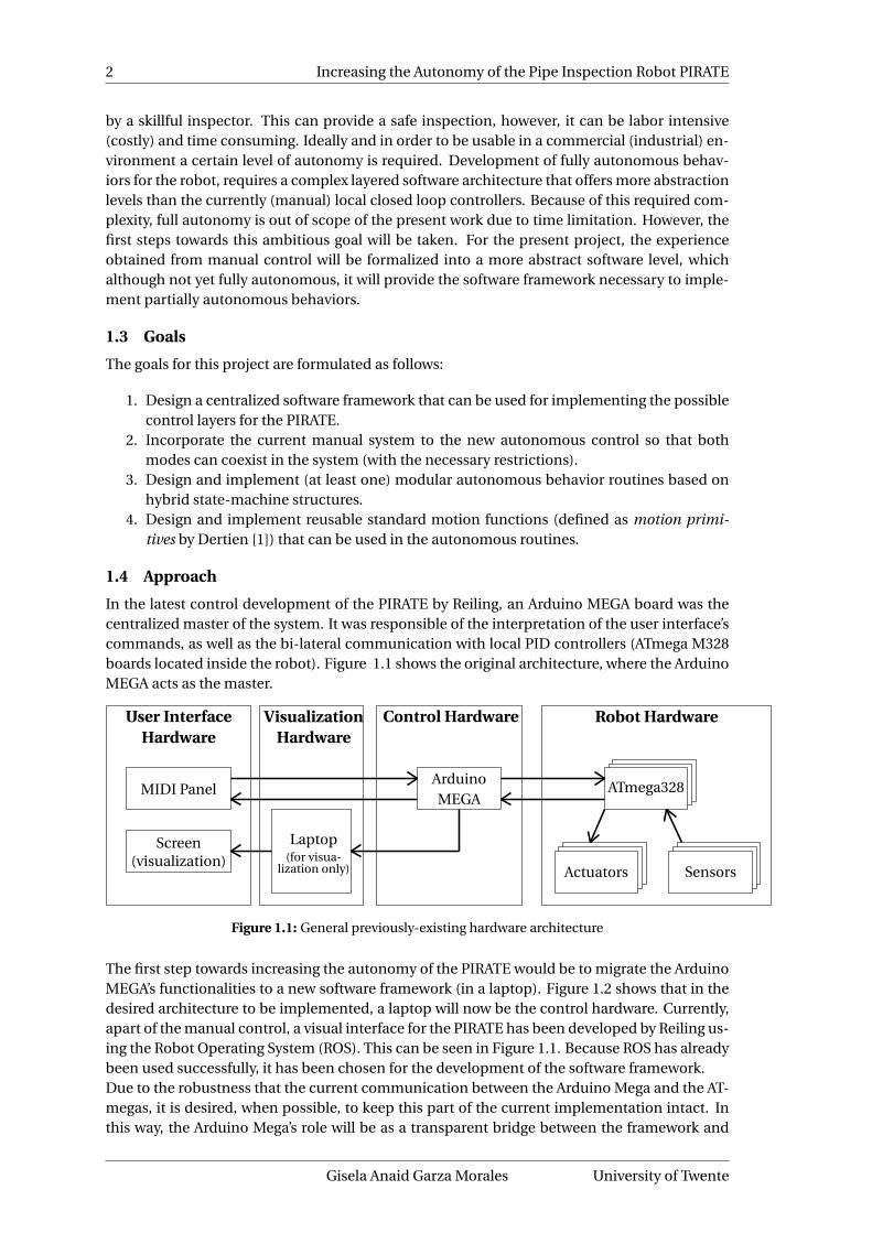
In the latest control development of the PIRATE by Reiling, an Arduino MEGA board was thecentralized master of the system. It was responsible of the interpretation of the user interface’scommands, as well as the bi-lateral communication with local PID controllers (ATmega M328boards located inside the robot). Figure 1.1 shows the original architecture, where the ArduinoMEGA acts as the master.
User InterfaceHardware
MIDI Panel
Screen(visualization)
Control Hardware
ArduinoMEGA
VisualizationHardware
Laptop(for visua-
lization only)
Robot Hardware
ATmega328
Actuators Sensors
Figure 1.1: General previously-existing hardware architecture
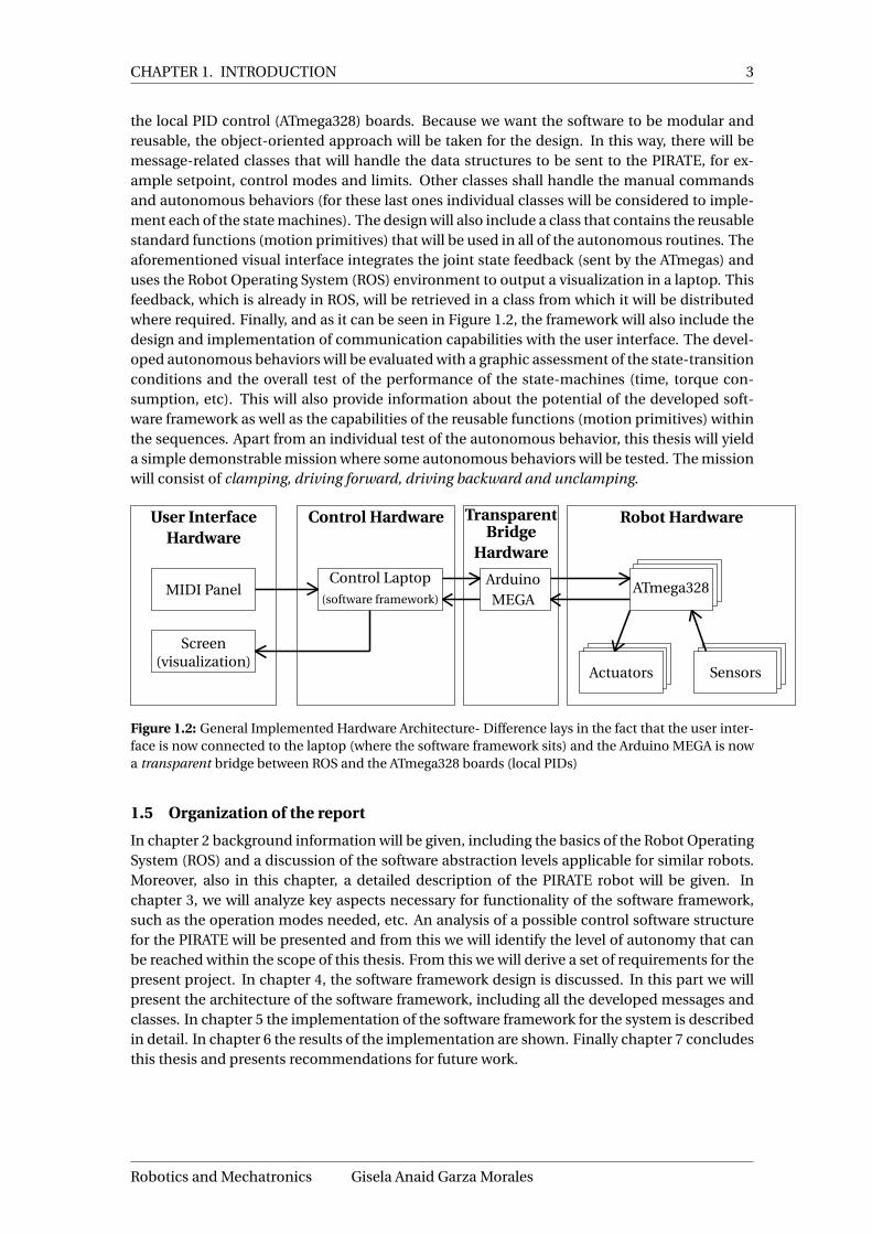
The first step towards increasing the autonomy of the PIRATE would be to migrate the ArduinoMEGA’s functionalities to a new software framework (in a laptop). Figure 1.2 shows that in thedesired architecture to be implemented, a laptop will now be the control hardware. Currently,apart of the manual control, a visual interface for the PIRATE has been developed by Reiling us-ing the Robot Operating System (ROS). This can be seen in Figure 1.1. Because ROS has alreadybeen used successfully, it has been chosen for the development of the software framework.Due to the robustness that the current communication between the Arduino Mega and the AT-megas, it is desired, when possible, to keep this part of the current implementation intact. Inthis way, the Arduino Mega’s role will be as a transparent bridge between the framework and
Gisela Anaid Garza Morales University of Twente
CHAPTER 1. INTRODUCTION 3
the local PID control (ATmega328) boards. Because we want the software to be modular andreusable, the object-oriented approach will be taken for the design. In this way, there will bemessage-related classes that will handle the data structures to be sent to the PIRATE, for ex-ample setpoint, control modes and limits. Other classes shall handle the manual commandsand autonomous behaviors (for these last ones individual classes will be considered to imple-ment each of the state machines). The design will also include a class that contains the reusablestandard functions (motion primitives) that will be used in all of the autonomous routines. Theaforementioned visual interface integrates the joint state feedback (sent by the ATmegas) anduses the Robot Operating System (ROS) environment to output a visualization in a laptop. Thisfeedback, which is already in ROS, will be retrieved in a class from which it will be distributedwhere required. Finally, and as it can be seen in Figure 1.2, the framework will also include thedesign and implementation of communication capabilities with the user interface. The devel-oped autonomous behaviors will be evaluated with a graphic assessment of the state-transitionconditions and the overall test of the performance of the state-machines (time, torque con-sumption, etc). This will also provide information about the potential of the developed soft-ware framework as well as the capabilities of the reusable functions (motion primitives) withinthe sequences. Apart from an individual test of the autonomous behavior, this thesis will yielda simple demonstrable mission where some autonomous behaviors will be tested. The missionwill consist of clamping, driving forward, driving backward and unclamping.
User InterfaceHardware
MIDI Panel
Screen(visualization)
Control Hardware
Control Laptop(software framework)
TransparentBridge
Hardware
ArduinoMEGA
Robot Hardware
ATmega328
Actuators Sensors
Figure 1.2: General Implemented Hardware Architecture- Difference lays in the fact that the user inter-face is now connected to the laptop (where the software framework sits) and the Arduino MEGA is nowa transparent bridge between ROS and the ATmega328 boards (local PIDs)
1.5 Organization of the report
In chapter 2 background information will be given, including the basics of the Robot OperatingSystem (ROS) and a discussion of the software abstraction levels applicable for similar robots.Moreover, also in this chapter, a detailed description of the PIRATE robot will be given. Inchapter 3, we will analyze key aspects necessary for functionality of the software framework,such as the operation modes needed, etc. An analysis of a possible control software structurefor the PIRATE will be presented and from this we will identify the level of autonomy that canbe reached within the scope of this thesis. From this we will derive a set of requirements for thepresent project. In chapter 4, the software framework design is discussed. In this part we willpresent the architecture of the software framework, including all the developed messages andclasses. In chapter 5 the implementation of the software framework for the system is describedin detail. In chapter 6 the results of the implementation are shown. Finally chapter 7 concludesthis thesis and presents recommendations for future work.
Robotics and Mechatronics Gisela Anaid Garza Morales

4 Increasing the Autonomy of the Pipe Inspection Robot PIRATE
2 Background
To place the design of the software framework into perspective, background information isgiven on the ROS and on software control architectures. Also, some related work is presented.
2.1 Robot Operating System (ROS)
The Robot Operating System (ROS) is an open-source flexible framework for writing robot soft-ware. It is a collection of tools, libraries, and conventions that aim to simplify the task of creat-ing complex and robust robot behavior across a wide variety of robotic platforms 1.
ROS supports a wide range of sensors and algorithms. For the user it is also easy to add newparts, since Python and C++ (amongst others) are supported as programming languages and itcan be used with the most popular IDEs 2.
In ROS, a running instance of a program is called a node 3, which is basically an executable tocommunicate with other nodes through a network structure.
In order for several nodes to run at the same time, they must be able to communicate with oneanother. The part of ROS that facilitates this communication is called the ROS master.
The primary mechanism that ROS nodes use to communicate is to send messages, which haveparticular data type(s) and organized into named topics. Message exchange is based on thepublish/subscribe pattern: a node that wants to share information will publish messages on theappropriate topic or topics; a node that wants to receive information will subscribe (listen) tothe topic or topics that it’s interested in. The ROS master takes care of ensuring that publishersand subscribers can find each other 4. Figure 2.1 shows the publish/subscribe pattern used inROS.
In ROS, all messages on the same topic must be of the same data type. Inside ROS, these mes-sages are transformed to header files, where the user defined fields are placed in structs, makingthe communication more robust. Another benefit of using a message passing system is that itforces the implementation of clear interfaces between the nodes in the system, thereby im-proving encapsulation and promoting code reuse.
Publisher node Subscriber node
TopicPublication Subscription
Figure 2.1: Publish/Subscribe structure in ROS.
Because the publish/subscribe system is anonymous and asynchronous, the data can be easilycaptured and replayed without any changes to code. Furthermore, if synchronous request/re-sponse interactions are required between processes, the ROS provides this capability using ser-vices.
1ROS.org - About ROS http://www.ros.org/about-ros/2ROS.org - IDEs http://wiki.ros.org/IDEs3ROS.org - Understanding Nodes http://wiki.ros.org/ROS/Tutorials/UnderstandingNodes4ROS.org - Understanding Topics http://wiki.ros.org/ROS/Tutorials/UnderstandingTopics
Gisela Anaid Garza Morales University of Twente

CHAPTER 2. BACKGROUND 5
While topics (anonymous publish/subscribe) and services (remote procedure calls) cover mostof the communication use cases in robotics, sometimes it is necessary to initiate a goal-seekingbehavior, monitor its progress, be able to preempt it along the way, and receive notificationwhen it is complete. ROS provides actions for this purpose. Actions are like services except theycan report progress before returning the final response, and they can be preempted at any timeby the caller 5.
For more detailed information about ROS, its components and features, the reader is advisedto visit its website 6 or to take a look at [16] and [17].
2.2 UML basics
In this section, the basic definitions and most common features of UML will be discussed. Thisdoes not aim to be in any way a comprehensive summary on UML, but rather provide the basefor the reader to understand the diagrams presented in this thesis.
The Unified Model Language (UML) is a language for expressing the constructs and relation-ships of complex systems [18]. This modeling approach is more complete than other methodsand is particularly efficient for modeling real-time, embedded systems. The basic features ofUML discussed in the present thesis are:
1. Class diagrams2. Use cases
2.2.1 Class diagrams
In object-oriented programming, the term class is used to describe an abstraction of the com-mon properties from a set containing many similar objects [18]. In this sense, a class can bethough of as the type of object. In UML, classes are shown using rectangles with the name ofthe class inside a rectangle [18]. A very common variation of this uses a three-segment rectan-gle, from which the top mentions the name of the class, in the middle the attributes (properties)and in the bottom the member functions (behaviors) related to such class.
Pirate
1
¿usesÀ
1
1¿usesÀ
*
Joint state
- angleJoint : double[18]# springConstant : int
- getJointState() : double[18]+ publishJointState() : void
¿interfaceÀUser Interface
- inputChannel : int- value : int
Pirate Control
+ controlMode : int# state : int
+ publishManual() : bool+ publishAutonomous() : bool
Figure 2.2: Example of a UML class diagram for PIRATE control
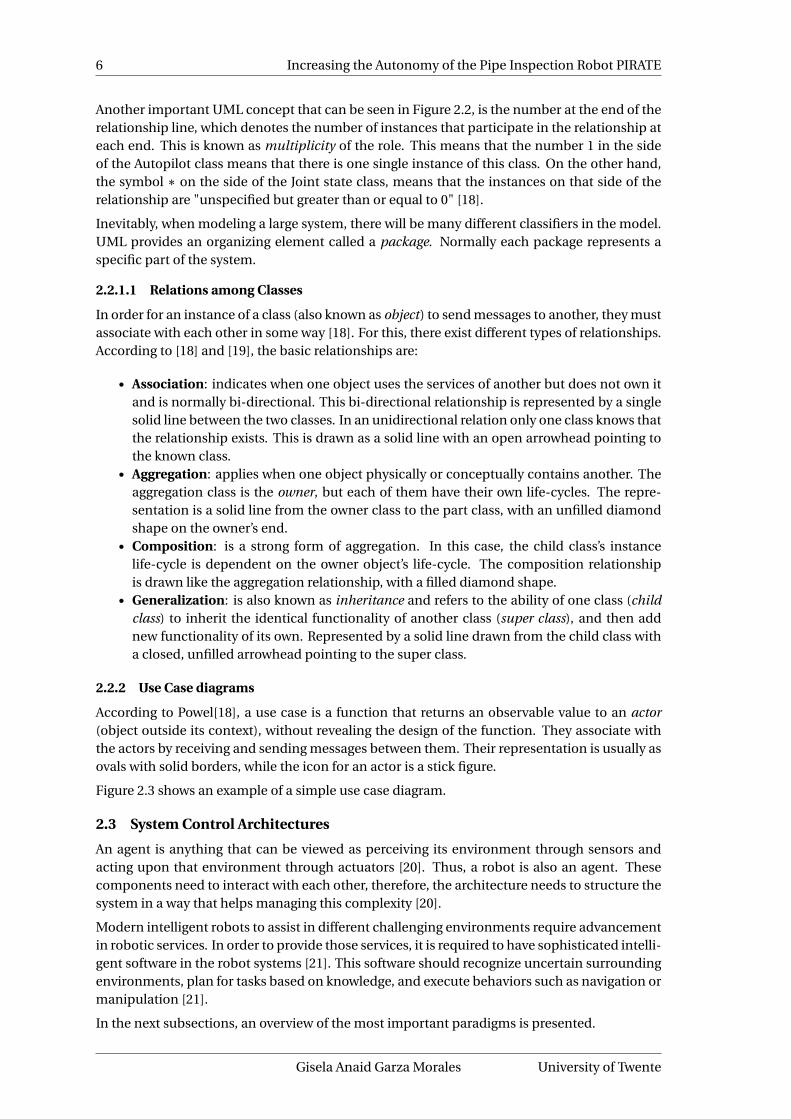
Figure 2.2 shows an example of a simple class diagram. It is possible to find three classes,namely Pirate Control, User Interface and Joint State. Inside the classes, it is possible to seethe attributes, member functions (behaviors) and the access modifiers. The access modifiersrestrict the accessibility to the attributes and member functions and can be public (+), private(-) or protected(#).
5ROS.org - Core components http://www.ros.org/core-components/6ROS.org - http://www.ros.org
Robotics and Mechatronics Gisela Anaid Garza Morales
6 Increasing the Autonomy of the Pipe Inspection Robot PIRATE
Another important UML concept that can be seen in Figure 2.2, is the number at the end of therelationship line, which denotes the number of instances that participate in the relationship ateach end. This is known as multiplicity of the role. This means that the number 1 in the sideof the Autopilot class means that there is one single instance of this class. On the other hand,the symbol ∗ on the side of the Joint state class, means that the instances on that side of therelationship are "unspecified but greater than or equal to 0" [18].
Inevitably, when modeling a large system, there will be many different classifiers in the model.UML provides an organizing element called a package. Normally each package represents aspecific part of the system.
2.2.1.1 Relations among Classes
In order for an instance of a class (also known as object) to send messages to another, they mustassociate with each other in some way [18]. For this, there exist different types of relationships.According to [18] and [19], the basic relationships are:
• Association: indicates when one object uses the services of another but does not own itand is normally bi-directional. This bi-directional relationship is represented by a singlesolid line between the two classes. In an unidirectional relation only one class knows thatthe relationship exists. This is drawn as a solid line with an open arrowhead pointing tothe known class.
• Aggregation: applies when one object physically or conceptually contains another. Theaggregation class is the owner, but each of them have their own life-cycles. The repre-sentation is a solid line from the owner class to the part class, with an unfilled diamondshape on the owner’s end.
• Composition: is a strong form of aggregation. In this case, the child class’s instancelife-cycle is dependent on the owner object’s life-cycle. The composition relationshipis drawn like the aggregation relationship, with a filled diamond shape.
• Generalization: is also known as inheritance and refers to the ability of one class (childclass) to inherit the identical functionality of another class (super class), and then addnew functionality of its own. Represented by a solid line drawn from the child class witha closed, unfilled arrowhead pointing to the super class.
2.2.2 Use Case diagrams
According to Powel[18], a use case is a function that returns an observable value to an actor(object outside its context), without revealing the design of the function. They associate withthe actors by receiving and sending messages between them. Their representation is usually asovals with solid borders, while the icon for an actor is a stick figure.
Figure 2.3 shows an example of a simple use case diagram.
2.3 System Control Architectures
An agent is anything that can be viewed as perceiving its environment through sensors andacting upon that environment through actuators [20]. Thus, a robot is also an agent. Thesecomponents need to interact with each other, therefore, the architecture needs to structure thesystem in a way that helps managing this complexity [20].
Modern intelligent robots to assist in different challenging environments require advancementin robotic services. In order to provide those services, it is required to have sophisticated intelli-gent software in the robot systems [21]. This software should recognize uncertain surroundingenvironments, plan for tasks based on knowledge, and execute behaviors such as navigation ormanipulation [21].
In the next subsections, an overview of the most important paradigms is presented.
Gisela Anaid Garza Morales University of Twente

CHAPTER 2. BACKGROUND 7
PiratePirate
Send Manual command
Send Autonomous command
Stop robotUser
Figure 2.3: Example of a Use Case diagram for the PIRATE
2.3.1 SPA- The Hierarchical Paradigm
This is the oldest approach which has been used to compose robot systems. It is often referredto as the Sense, Plan, Act (SPA) approach, which is traditionally sequential and orderly [20].
This approach has two important architectural features [22]:
1. Control flow is unidirectional and linear: Information flows from sensors to world model(perception and modeling) to plan to effectors (task execution and motor control).
2. Execution of an SPA plan is analogous to the execution of a computer program: Both arebuilt of primitives composed using partial orderings, conditionals, and loops and theintelligence of the system resides in the planner, not the execution mechanism.
Sensors
Perc
epti
on
Mo
del
ing
Pla
nn
ing
Task
Exe
cuti
on
Mo
tor
Co
ntr
ol
Actuators
Figure 2.4: SPA Approach. Figure from [23]
The main disadvantage of this approach results precisely from the sequential flow shown inFigure 2.4. In this case, the plan usually takes more time because of the need to compute theactions. Because of this, the output signal to the actuator is very delayed and results in "jittery"behavior. Furthermore, it faces the fact that, when the plan is ready, the environment may havechanged already and thus, when the planner is finished it may have generated an obsolete plan.
2.3.2 The three-layer architecture
The three-layer architecture consists of three components: a reactive feedback control mecha-nism, a reactive plan execution mechanism, and a mechanism for performing time-consumingdeliberative computations. These components run as separate computational processes. Thefirst layer is called Controller, the second one Sequencer and the deliberative one is referred toas Deliberator.
The main characteristics of the three layers according to Gat[22] are:
1. Controller: consists of one or more feedback control loops, tightly coupling sensors toactuators. Contains functions (called primitive behaviors or skills) that are called to ac-
Robotics and Mechatronics Gisela Anaid Garza Morales

8 Increasing the Autonomy of the Pipe Inspection Robot PIRATE
Deliberate Layer(Deliberator)
Sequential Layer(Sequencer)
Reactive Layer(Controller)
Figure 2.5: Three layer architecture. Figure from [21]
tion by the Sequencer, to form a more complex task-achieving behavior. Main constraintis that the computing of the algorithm must be fast (real-time).
2. Sequencer: its job is to select which primitive Behavior the controller should use at acertain time, and to supply parameters for the Behavior. By changing primitive Behaviorsat strategic moments the robot can perform useful tasks and sometimes cope with non-idealistic situations. Because of this, the sequencer must be able to respond conditionallyto the current situation, by adding steps, performing additional checks, etc.
3. Deliberator: takes care of the time-consuming computations. Usually tasks are plan-ning, search, vision or any complex processing algorithms. Several Behavior transitionscan occur between the invoking and producing a result. It produces plans or respondsqueries for the sequencer.
2.3.3 Layered control structure
In mechatronic systems, the dynamic behavior of the plant/machine to be controlled is essen-tial for the functionality of the system.
According to this, the control processes should be divided over the range of hard and soft real-time. To make this apparent, a layered priority structure is proposed by Broenink et al. in [24],which is based on Bennet[25]. This structure has since then been modified, and the existingapproach was published by Broenink[26] in 2014 and is depicted in Figure 2.6. It is an archi-tecture used for robotic systems, containing the physical/mechanical plant (robot) at the rightand the (embedded) control software at the left. In the middle sit the parts that transform thesignals between the two domains. Again in this architecture, similar to the one shown in sub-section 2.3.2, the control layers are used to indicate the priority (and abstraction) of the controlprocesses.
The embedded control software part is structured in layers according to Broenink et al. [26] in2012:
1. Loop control: contains the control algorithms for controlling the actuators. Since theactuators require an update of their setpoint every sampling period, this layer is imple-mented as hard real-time.
2. Sequence control: can be described as a task level controller, which enables and feeds theloop controllers with setpoints and necessary parameters. This part can be implementedin soft real-time.
3. Supervisory control: is a strategy controller. It performs calculations, which take con-siderable computing time (compared to the sampling period). The result of these cal-
Gisela Anaid Garza Morales University of Twente

CHAPTER 2. BACKGROUND 9
Safe
tyla
yer
Use
rIn
terf
ace
Sup
ervi
sory
Nonreal-time
con
tro
l&in
tera
ctio
n
Seq
uen
ceco
ntr
ol
Softreal-time
Hardreal-time
Lo
op
con
tro
l
Mea
s.&
Act
. D/A Poweramplifier
A/DFiltering /
Scaling
Actuators
PhysicalSystem
Sensors
Embedded Control Software I/O Hardware Plant
Figure 2.6: Layered software architecture for embedded systems. Figure from [27]
culations to determine the tasks to be sent to the Sequence controller. Typical supervi-sory control tasks include path planning, vision algorithms and environment mapping,among others.
4. Safety layer: checks for safety issues on all control levels (this is why it is drawn behindthe other layers). In this level, all signals going to the hardware are reviewed.
5. Measurement & Actuation: this layer implements different techniques for signal condi-tioning in order to adapt the variable ranges to the signal levels of the hardware.
Comparing with the three layered approach, discussed in subsection 2.3.2, it is possible to seethe similarities between the Supervisory control with the Deliberator, the Sequence controlwith the Sequencer and the Loop control with the Controller. However, an important differencepresent in this layered control structure is the definition of the real-time requirements for eachof the layers, as well as the inclusion of the Safety and the Measurement and Actuation layers.This serves to give a more realistic view of a software architecture for robots.
2.4 The PIRATE robot
2.4.1 Design background
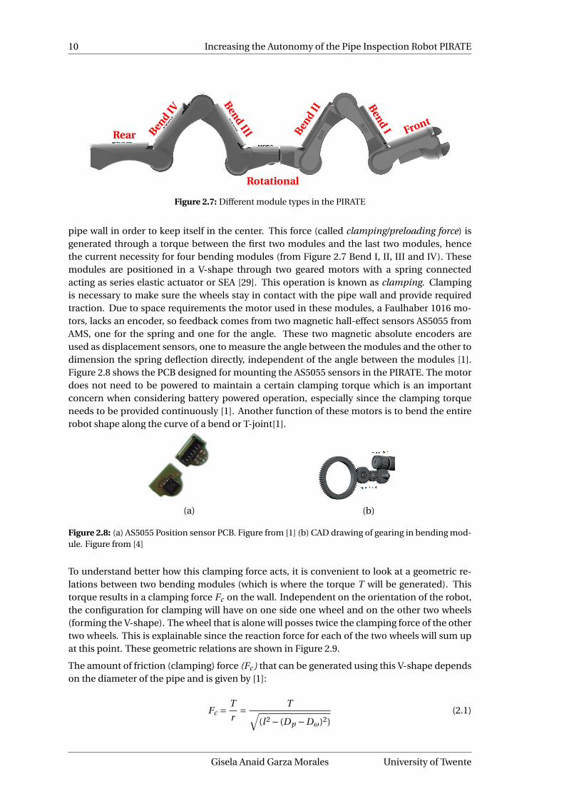
The PIRATE design proposed by E. Dertien’s PhD thesis [1] allows for a separation in mod-ules where each has its specific function. Advantages of modularity are: interchangeability forrepairs and easiness to remove or add modules depending on the application. Furthermore,manufacturability of the system increases when the modules have identical shapes and parts.In early designs, the PIRATE had seven modules for which reductions have been discussed andproposed by Reemeijer in 2010 [10]. Nevertheless, the design has changed over time [28] andthe current design, differs from the one presented in Dertien’s PhD thesis[1] which consisted infive modules. The latest model of the PIRATE has again seven physical modules. This consistsof the former five plus one module in the front and one in the back to integrate vision and il-lumination capabilities to the robot. Amongst these seven modules, four different types, all ofwhich have the possibility to be driven by the wheels, can be distinguished (see Figure 2.7):
1. Bend module2. Rear module3. Front module4. Rotational module
2.4.1.1 Bend Module
The bend module is perhaps the most crucial part in the robot’s design. To drive in a stablemanner through a pipe, the robot always needs to constantly exert a certain force on the
Robotics and Mechatronics Gisela Anaid Garza Morales
10 Increasing the Autonomy of the Pipe Inspection Robot PIRATE
Rear BendIV
BendIII
Rotational
Bend
II BendI Front
Figure 2.7: Different module types in the PIRATE
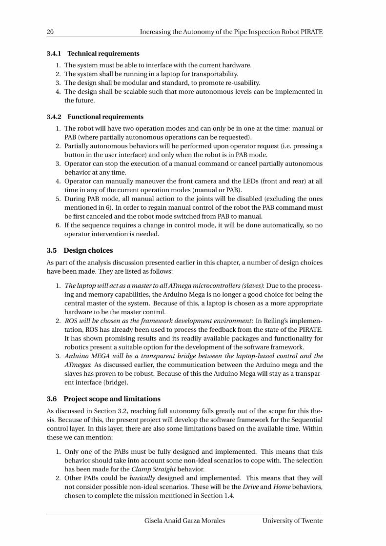
pipe wall in order to keep itself in the center. This force (called clamping/preloading force) isgenerated through a torque between the first two modules and the last two modules, hencethe current necessity for four bending modules (from Figure 2.7 Bend I, II, III and IV). Thesemodules are positioned in a V-shape through two geared motors with a spring connectedacting as series elastic actuator or SEA [29]. This operation is known as clamping. Clampingis necessary to make sure the wheels stay in contact with the pipe wall and provide requiredtraction. Due to space requirements the motor used in these modules, a Faulhaber 1016 mo-tors, lacks an encoder, so feedback comes from two magnetic hall-effect sensors AS5055 fromAMS, one for the spring and one for the angle. These two magnetic absolute encoders areused as displacement sensors, one to measure the angle between the modules and the other todimension the spring deflection directly, independent of the angle between the modules [1].Figure 2.8 shows the PCB designed for mounting the AS5055 sensors in the PIRATE. The motordoes not need to be powered to maintain a certain clamping torque which is an importantconcern when considering battery powered operation, especially since the clamping torqueneeds to be provided continuously [1]. Another function of these motors is to bend the entirerobot shape along the curve of a bend or T-joint[1].
(a) (b)
Figure 2.8: (a) AS5055 Position sensor PCB. Figure from [1] (b) CAD drawing of gearing in bending mod-ule. Figure from [4]
To understand better how this clamping force acts, it is convenient to look at a geometric re-lations between two bending modules (which is where the torque T will be generated). Thistorque results in a clamping force Fc on the wall. Independent on the orientation of the robot,the configuration for clamping will have on one side one wheel and on the other two wheels(forming the V-shape). The wheel that is alone will posses twice the clamping force of the othertwo wheels. This is explainable since the reaction force for each of the two wheels will sum upat this point. These geometric relations are shown in Figure 2.9.
The amount of friction (clamping) force (Fc ) that can be generated using this V-shape dependson the diameter of the pipe and is given by [1]:
Fc = T
r= T√
(l 2 − (Dp −Dω)2)(2.1)
Gisela Anaid Garza Morales University of Twente

CHAPTER 2. BACKGROUND 11
Figure 2.9: Geometric relations causing the clamping forces and torque. Figure from [1]
where l is the length of a module, Dω is the wheel diameter, Dp the pipe diameter. The currentversion of the robot has a Dω= 0.046m and the modules have a l=0.09m. Also for the presentwork, a standard pipe diameter Dp =0.09m was used, since it presented the average case sce-nario.
The bending module requires a gear train to transfer power from the self-locking worm gearvia the spring to the joint in order to clamp [1]. An IPM (Ideal Physical Model) of the system(without controller) is given in Figure 2.10. The CAD design of the system is given in Figure 2.11.Note that each mechanism drives the geared edge on the next module.
Figure 2.10: IPM of the bend drive.Figure from [1]
Figure 2.11: CAD drawing of complete bending gear system showing worm gear, spring and clutch.Figure from [1]
2.4.1.2 Rear Module
The rear module is the one that currently holds the connection from the exterior to the robot(using a tethered cable). This is possible through a standard Ethernet plug (RJ45 connector)that carries both communication and power buses. It contains also vision capabilities (the rearcamera) that is used to obtain images from the pipe from the back point of view of the robot.This camera is fixed, so it has no pan or tilt capabilities. Currently this module is not activelycontrolled, but its position is measured by the same kind of sensors as the ones in the bendmodule. This module also has LEDs which provide illumination for the back part of the robot.
Robotics and Mechatronics Gisela Anaid Garza Morales

12 Increasing the Autonomy of the Pipe Inspection Robot PIRATE
2.4.1.3 Front Module
The front module’s function is to provide vision from what stands in front of the robot througha camera (the front camera), which can tilt and pan by itself to provide better vision for ex-ploration. The front of this module has a semi-spherical plastic dome to protect the camerawithout taking the vision possibilities. For the pan and tilt of the camera motors along witha linear guidance are used, and can be controlled using position or PWM control. The frontmodule itself is also capable of tilting, which can be controlled also by position or PWM mode,and which uses a Pololu motor (which currently has a gear ratio that makes it more "sensitive"than the bending modules). The same kind of sensors for angle measurement are used in thismodule. It also has LEDs which provide illumination for the front part of the robot.
2.4.1.4 Rotational Module
The rotation module is located in the middle of the robot. It consists of two parts which areconnected by a Faulhaber 1516 motor with incremental encoder. The motor is positioned ina longitudinal direction and is able to rotate all front modules compared to the back modules,clockwise as well as anticlockwise. Normally in a rotation procedure, either the front (front andfirst two bend modules) or the back part (rear and last two bend modules) of the robot willbe clamped. When commanded the part that offers the least resistance will rotate, so in thiscase the part that is unclamped (either rear or front) will rotate. The motor and encoder of themodule are controlled using the attached motor controller circuit.
2.4.1.5 Wheels - Drive Mechanism
Wheels are attached between each module at the joint and at the end of the robot and thecurrent design has 6 wheels in total (see Figure 2.7). In previous iterations of the design, it hadonly two driven wheels, whereas the current version, every wheel has a motor mounted inside -a so called "in wheel drive". A coupling between motor shaft and wheel has to be implementedwhich decouples five of the degrees of freedom while connecting only one (traction). Figure2.12 shows the wheel with decoupling, bearing, connector shaft and geared DC motor. TheO-ring which is used as tire is not shown in the figure.
Figure 2.12: Exploded view of in wheel drive mechanism showing (from left to right) wheel with rota-tional decoupling, bearing, linear decoupling and motor - image from [1]
2.4.2 Electronics
The electronic system design uses a modular approach rather than a centralized system. Thisdecision reduced considerably the amount of wiring and benefited the real-time capabilities ofthe control system. The robot has been controlled using a Master-slave node approach. Thecommunication is possible through an Arduino Mega 7 board as master. This board is encapsu-lated in a box, where the connectors for power (type DC barrel power jack) and communication(RJ-45 that connects to the PIRATE robot, USB type-A that originally connected with the userinterface [now is unused] and a USB type-B that connects to the laptop) are attached. Theboard for the Arduino Mega is referred to as Pirate Bay and it is depicted in Figure 2.13. ThePirate Bay also holds the connections for the rear and front cameras of the PIRATE robot.
7Arduino Mega board - https://www.arduino.cc/en/Main/arduinoBoardMega
Gisela Anaid Garza Morales University of Twente

CHAPTER 2. BACKGROUND 13
Figure 2.13: Pirate Bay
The modules mentioned in subsection 2.4.1, have one (or two in case of the rotational andfront module) small board measuring 15×27 mm, shown in Figure 2.14. The board includes asmicrocontroller the ATmega328p 8, which is the most common controller on Arduino boards.Each of these boards are referred to as PICO boards. Apart from the microcontroller, the boardscontain a H-bridge (model A3906), a regulator (model LTM8020), a RS485 transceiver (modelLTC2850) and a compass (model FXOS8700CQ). The PICO board is shown in Figure 2.14. As itcan be seen, each PICO board can control up to two motors and receive feedback from up totwo connected sensors. In the back part of the PICO board, DF57 connectors were added. Thischoice was based on the fact that they are smaller and come with pre-crimped wires, whichimproves the reliability. Each of the PICO boards can connect up to two sensors and two mo-tors and they provide the RS485 communication using a daisy chain structure (so each boardhas one input and one output connection) throughout the robot, which effectively reduces thewiring length and makes it easy to maintain.
RS485 driverMicrocontroller
H-bridge
CompassRegulator
(a) PICO Board front
RS485bus
Motor0
Sensor0
RS485bus
Motor 1 Sensor 1
(b) PICO Board back
Figure 2.14: PICO board -front side (a) and back side (b)
2.4.3 Control
The robot currently contains a total of nine PICO boards (one per bending module, one in therear, two in the rotational one and two in the front). The boards are numbered starting from 20(at the front) to 28 (in the rear module). The need for having two boards in the rotational one isbecause this module is composed of two parts and has control of two drive (wheel) motors andthe rotation motor. Since each PICO board can control up to two motors, a second board hadto be added. This added board was also connected to the IMU sensor. In the front module, thesame situation applies, it controls the motor that tilts the module, but also two other motorsfor pan and tilt of the camera, which required again two PICO boards. The LED in the front isattached to the spare motor connection of one of these boards.
8ATmega328p board - http://www.atmel.com/devices/atmega328p.aspx
Robotics and Mechatronics Gisela Anaid Garza Morales

14 Increasing the Autonomy of the Pipe Inspection Robot PIRATE
Depending on the function of the module (and excluding the rear module which is not activelycontrolled), the corresponding PICO board can be configured for different types of control. Bydefault all the modules can be controlled using direct PWM to the motor. Table 2.1 shows theconnections of the boards and the type of control they can have (for the module’s names seeFigure 2.7).
Table 2.1: Connections and type of control in the PICO boards
SlaveNo.
Located inModule
Motor 0 Motor 1Sensor 0 Sensor 1
Connection Control Connection Control
20 Front Tilt cameraPWM/
PositionPan camera
PWM/Posi-tion
Tilt camera Pan Camera
21 Front Tilt frontPWM/
PositionLEDs PWM Angle N/A
22 Bend I BendPWM /Torque
DrivePWM/
VelocityAngle Spring
23 Bend II BendPWM/Torque
DrivePWM/
VelocityAngle Spring
24 Rotational N/A N/A DrivePWM/
VelocityIMU N/A
25 Rotational Rotate Position DrivePWM/
VelocityAngle N/A
26 Bend III BendPWM/Torque
DrivePWM/
VelocityAngle Spring
27 Bend IV BendPWM/Torque
DrivePWM/
VelocityAngle Spring
28 Rear N/A N/A LEDs PWM Angle N/A
2.4.3.1 Torque control
As seen in Table 2.1, in the four bending modules torque control is implemented using themeasurement of the spring deflection. An IPM of the drive train developed for 20sim simu-lation in [1] is shown in Figure 2.15. More recently, a PID control loop was implemented inthe corresponding PICO boards using the spring deflection as controller feedback signal. Cal-culating the spring deflection is elaborate because the software needs to track the amount ofrevolutions in the gearing. In this case, the first gear stage in the motor (1:64) is never taken intoaccount. The second stage (worm gear) is 24:1 and the third stage (from spring to the joint) is58:16, which gives a total gearing of 87:1. The spring position is calculated in raw end-stageangle units (i.e. with a 87:1 ratio) which means that the spring constant felt is multiplied by3.6252 ×3.168 = 41.6mN m/deg .
Figure 2.15: Schematic overview of the clamp control setup in 20sim. Figure from [1]
2.4.3.2 PWM
As we have seen from Table 2.1, the predominant option to move the motors is by using PWM,as this gives the flexibility to control the motor directly, which in some cases can be extremelyuseful. The case of the wheels (drive) is a good example. To move the drive motors PWM ispreferred, as this will allow wheels to spin at different velocities. In reality PWM is actually feedforward velocity control, as voltage is directly related to speed (considering an ideal motor).In
Gisela Anaid Garza Morales University of Twente

CHAPTER 2. BACKGROUND 15
the sampling routine (every 50Hz) the encoder position is differentiated in order to yield a mea-sure of the velocity. The maximum setpoint that can be sent by the user interface is equivalentto approximately 170mm/s.
2.4.3.3 Position control
For the front module’s tilt as well as for the front camera’s tilt and pan position control is avail-able. This is again implemented with a similar PID controller in the respective PICO boards.For this, the current spring angle’s position is used as feedback.
2.4.4 Motion primitives
In [1], the concept of motion primitives is introduced. They refer to the smallest functionallymeaningful action that the PIRATE robot can perform. According to this, each robot action canbe broken down to a series of these motion primitives which are essentially: clamp, unclamp,drive, bend and rotate.
Also in the PhD thesis, these motion primitives are parameterized: drive has one parameter:the velocity. Whether wheels should turn clockwise or counter clockwise (depending on whichside of the pipe they touch) can be determined based on the joint angle information. clamp hasalso one parameter: the desired clamping force on the pipe wall. For the V-shape both bend-ing modules are used which get the same setpoint, only in opposite directions. The clampingtorque required should be compensated for the current pipe diameter which can be measuredwith the module angles. rotate has one parameter: the angleφ between both sides of the robot.bend has also one parameter: the desired radius γ for a certain module to curve along a gradualor sharp bend. Table 2.2 shows these parameters.
Table 2.2: Motion primitives. Table from [1]
Motion primitive Parameterdrive ω [rad/s]clamp τ [N]rotate φ [rad]bend γ [rad]
It is important to mention that not all these motion primitives may be required or even thatthey might need to be more precisely defined into functions for the new software framework.
Robotics and Mechatronics Gisela Anaid Garza Morales

16 Increasing the Autonomy of the Pipe Inspection Robot PIRATE
3 Analysis
In this chapter, the current system control architecture is discussed and the implications ofmoving to a more abstract layer are presented. Based on this, the requirements for the presentwork are listed.
3.1 Current system control architecture
As discussed in subsection 2.3.3, there are different layers for the embedded control software.Based on their description, it is possible to notice that the current state of the PIRATE robotis located in the so-called Loop control layer. This is given by the fact that the implementa-tion of the control loop is done locally in the ATmega328p microcontrollers (PICO boards) inreal-time. The setpoints to these controllers are sent every sampling period using the ArduinoMEGA (Pirate Bay). The system works as follows: the user interfaces with the system via a faderpanel. In this, setpoints for the different modules can be given and also control modes (i.e.torque, velocity, position or PWM mode depending on the type of module) can be changed.Additionally, there is a laptop used only for running a visualization in ROS (called Rviz1) whichcommunicates via RS232. The control setup is shown in Figure 3.1.
In the current state, all functionality (motors, sensors) are readily accessible through an in-terface for direct control. However, this manual operation is now the whole potential of thecurrent architecture. This, because the control is implemented in the Arduino MEGA micro-controller and there is a limitation in available memory and processing capabilities, would atsome point be exceeded if more complex control was implemented in the same manner.
Figure 3.1: Schematic overview of control setup implementation. Derivative of [1]
3.2 Analysis of a layered software architecture for the PIRATE
The overall fully autonomous control functions desired for the PIRATE, can be mapped into thelayered controller structure mentioned in Section 2.3.3.
This results in a structure as depicted in Figure 3.2. In it, it is important to notice that the SafetyLayer, just as in shown in Figure 2.6, expands throughout all the software layers. This becauseeach of them have their own safety methods to prevent damage to the robot. The loop controland its related safety are hard-real-time, because missed deadlines may result in unstable con-trol actions for the joints or in a system failure. In this level there are two function blocks: Jointcontrol and State estimation. Going towards more abstraction, the sequence control includesthe so-called Partially Autonomous Behaviors (PAB) and Robot state. Partially Autonomous Be-
1ROS.org - rviz http://wiki.ros.org/rviz
Gisela Anaid Garza Morales University of Twente

CHAPTER 3. ANALYSIS 17
haviors are sequential movements that execute by commanding the loop control and using thefeedback that the Robot State gets from the joints and IMU sensor. In this stage, because theresult has utility even after the deadline has passed, this is classified as soft-real-time. Finally,the supervisory control consists of the function blocks Mission Planning and World modeling.These functions do not influence the stability of the robot and therefore they are non-real-time.When implemented, this control layered structure would provide a fully autonomous behaviorfor the PIRATE.
World Modeling(vision, distance
sensors, pipe maps)
Mission Planning
Partially Autonomous Behaviors(clamp straight, clamp sideways, drive. . . )
Robot State(joint angles
and efforts)
Joint Control(7 joints)
State Estimation(joint states)
Joint I/O Joints
Safety
Supervisory control
Sequential control
Loop control
Hardware
used for
set of PAB sequences
limits/ setpoints / control modes
Figure 3.2: Functional structure for the PIRATE mapped onto the layered control software architectureAdapted from [30]
The analyzed possible structure consists of eight function blocks, which are described as:
• World modeling: The PIRATE is supposed to inspect pipes with different topologies anddiameters. In order to successfully perform autonomously, it is required that the mapof the inspected pipe is available on forehand, with the adequate level of detail such as:pipe junctions location, pipe diameters throughout the pipeline, etc. Information aboutthe active environment can also be collected in this function block, by using vision ordistance sensors, which in combination with the supplied world map will create an up-to-date model of the environment.
• Mission Planning: Consists of an AI planning algorithm, which normally takes two in-puts: user input for the mission (the specific tasks that are to be completed) and theinternal database of the pipe lines where the robot will be working in (world model). Theoutput of this algorithm is called the mission plan which is a sequence of Partially Au-tonomous Behaviors which are executed successively. If an error occurs, the PAB level
Robotics and Mechatronics Gisela Anaid Garza Morales

18 Increasing the Autonomy of the Pipe Inspection Robot PIRATE
will inform the Mission Planning, so that it can react accordingly by changing the worldmodel and the PAB sequence to create a new plan.
• Partially Autonomous Behaviors (PABs): In order for the PIRATE to be able to moveand inspect the pipe lines, it needs to move in various ways and perform different tasks(e.g.: enter the pipe, and inspect the different paths). These movements are split up insimple movements (e.g.: clamp straight, drive, take joints), which are called partially au-tonomous behaviors. The name comes from the idea that they are sequences by them-selves which by using feedback can perform small "autonomous" tasks. In the big scopeof autonomy for the PIRATE, however, these are merely partially autonomous as notmuch planning is involved. To perform motions, the PABs should be able to manipu-late the joint controllers by being able to send:
• Control modes• Setpoints• Limits
Based on the description of the tasks from Dertien’s PhD thesis from 2014 [1], it is possibleto define mainly six different partially autonomous behaviors in the PIRATE:
(a) Clamp Straight(b) Clamp Sideways(c) Home (Unclamp)(d) Take T-joint(e) Take Mitre-bend(f) Drive
• Robot State: This function block collects the information provided by the sensors on thestatus of the robot and transforms it to standard units (angles in radians, orientation indegrees, etc.). This information can be requested by other function blocks.
• Joint Control and State estimation: These two blocks are closely related because to-gether they form the PID loop controllers that are present in each of the PICO Boards.The Joint control part, sends the desired setpoints to the motor actuators and the Stateestimation gathers the information of the sensors and uses it as feedback for the PIDcontrol loop.
• Joint I/O: Each of the joints’ sensors (inputs) and actuators (outputs).• Joints: currently the PIRATE robot has 7 joints, which are referred to as modules and they
are discussed in detail in Subsection 2.4.1.
Designing and implementing these software architecture for full autonomy is too ambitious forthe time frame and scope of this thesis. Nonetheless, the present work proposes to take the firststeps in the design of the framework that can allow the control software to advance towards theSequential control layer. The considerations for this are analyzed in Section 3.3.
3.3 Considerations for moving towards the Sequential control layer
If more autonomy is desired for the robot, it is required, as mentioned before, to change the waythe hardware elements interact with each other, as the Arduino MEGA shouldn’t be the masterof the system anymore. For this, a possible solution is to move the tasks that the Arduino MEGAcurrently does to a computer based system. The Robot Operating System (ROS) is a suitableframework for the implementation, because of the readily available packages it has, such asthe ones for serial communication and the visualization part, from which this last is alreadyimplemented and would be reusable if the control is migrated.
As mentioned before, the developments that have been done from 2014 onwards have rendereda relatively stable system for manual commands. This is because a lot of effort has been putinto the communication routines between the PICO boards and the Arduino MEGA. For this
Gisela Anaid Garza Morales University of Twente

CHAPTER 3. ANALYSIS 19
reason, it is possible to contemplate that the Arduino MEGA can act as a transparent bridgebetween the PICO boards and the new computer-based master, while still performing theserobust communication routines.
In this way the computer can further become an intelligent master controller, which generatesthe setpoints based on sensory information and stored mission data. The transparent bridgewill send these signals to the local motor control boards as well retrieve the sensor’s data itreceives from a the internal serial bus on the robot to send feedback to the host computer.
Currently the Arduino MEGA’s task is to listen to the user interface inputs and generate set-points for the PICO boards, accordingly. Since this is a relatively easy task, migration to a ROSnode should not present complications. However, when more autonomous behaviors are de-sired, it implicates a necessary distinction of the different modes of operation that should bepresent in the PIRATE. Examples of these modes could be Manual and Partially AutonomousBehaviors, (PABs).
Having a system with different modes of operations has several implications on defining thecorrect interaction between them. The most important property of such a system, is the factthat only one of the modes should be active at a time, and the implementation should keepcareful track of which is the current mode.
Another situation to be taken into account when switching modes, is the fact that the PIRATEhas a camera in the front which can be adjusted in pan and tilt position. Furthermore, thereare also LEDS both in the front and the rear modules. Since these functionalities wouldn’t,in principle, be automated for now, and the fact that the user might need them at any time,it would be desired that they remain manually controllable during the execution of the moreautonomous operations. This could potentially be facilitated by separating the execution ofthe manual and PAB operation modes into two ROS nodes, which are independent and canrun concurrently. In this way, if a PAB mode is active it could, for example, restrict the accessof the manual mode to all the necessary modules, but the ones that control the camera and theLEDs.
Another important fact for correct mode interaction is that the coherence between the mes-sages (setpoint, control, etc.) when switching the operation modes should be assured, espe-cially if the modes are implemented in separate programs (nodes). This means that, for exam-ple, if the last operation mode was PAB and the last setpoint sent to one of the modules wasequal to 256, then if the mode is switched to manual, this setpoint remains until it is manuallymodified, thus it should not be restarted (this is undesired because, for example, sending a 0setpoint would cause the robot to move).
To protect the integrity of the robot, one of the most crucial necessities when dealing with apartially autonomous sequential program is the possibility to cancel the execution at any time,which should also be considered in the design of the system.
Even though the system will not reach the Supervisory layer directly, the programmed se-quences shall be able to cope with non-nominal situations. Such events can happen becauseof the rough environment in which the robot must work. An example of this would be that ifthe robot falls on its side, it should be able to recuperate the desired position.
3.4 Requirements
The basic requirements for the present work’s development are derived from the above discus-sion and are differentiated into technical (related to the physical system and the environment)and functional (related to the desired behavior).
Robotics and Mechatronics Gisela Anaid Garza Morales
20 Increasing the Autonomy of the Pipe Inspection Robot PIRATE
3.4.1 Technical requirements
1. The system must be able to interface with the current hardware.2. The system shall be running in a laptop for transportability.3. The design shall be modular and standard, to promote re-usability.4. The design shall be scalable such that more autonomous levels can be implemented in
the future.
3.4.2 Functional requirements
1. The robot will have two operation modes and can only be in one at the time: manual orPAB (where partially autonomous operations can be requested).
2. Partially autonomous behaviors will be performed upon operator request (i.e. pressing abutton in the user interface) and only when the robot is in PAB mode.
3. Operator can stop the execution of a manual command or cancel partially autonomousbehavior at any time.
4. Operator can manually maneuver the front camera and the LEDs (front and rear) at alltime in any of the current operation modes (manual or PAB).
5. During PAB mode, all manual action to the joints will be disabled (excluding the onesmentioned in 6). In order to regain manual control of the robot the PAB command mustbe first canceled and the robot mode switched from PAB to manual.
6. If the sequence requires a change in control mode, it will be done automatically, so nooperator intervention is needed.
3.5 Design choices
As part of the analysis discussion presented earlier in this chapter, a number of design choiceshave been made. They are listed as follows:
1. The laptop will act as a master to all ATmega microcontrollers (slaves): Due to the process-ing and memory capabilities, the Arduino Mega is no longer a good choice for being thecentral master of the system. Because of this, a laptop is chosen as a more appropriatehardware to be the master control.
2. ROS will be chosen as the framework development environment: In Reiling’s implemen-tation, ROS has already been used to process the feedback from the state of the PIRATE.It has shown promising results and its readily available packages and functionality forrobotics present a suitable option for the development of the software framework.
3. Arduino MEGA will be a transparent bridge between the laptop-based control and theATmegas: As discussed earlier, the communication between the Arduino mega and theslaves has proven to be robust. Because of this the Arduino Mega will stay as a transpar-ent interface (bridge).
3.6 Project scope and limitations
As discussed in Section 3.2, reaching full autonomy falls greatly out of the scope for this the-sis. Because of this, the present project will develop the software framework for the Sequentialcontrol layer. In this layer, there are also some limitations based on the available time. Withinthese we can mention:
1. Only one of the PABs must be fully designed and implemented. This means that thisbehavior should take into account some non-ideal scenarios to cope with. The selectionhas been made for the Clamp Straight behavior.
2. Other PABs could be basically designed and implemented. This means that they willnot consider possible non-ideal scenarios. These will be the Drive and Home behaviors,chosen to complete the mission mentioned in Section 1.4.
Gisela Anaid Garza Morales University of Twente

21
4 Software Framework Design
This chapter describes the steps followed to obtain a competent software framework that in-tegrates all the requirements defined previously in order for the general software architectureto reach the Sequential control layer. First of all, an overview of the general design made isshown. After this, each of its parts is discussed in detail, along with the reasoning behind thedesign choices.
4.1 General framework design
The general software architecture is composed of different classes which perform specific func-tions. The considerations taken to define the required classes, were based on the desired goalsand requirements.
The main functions that must be covered are:
1. Communicate ROS with user interface (read/write).2. Translate user interface commands to instructions (setpoints, control modes or limits)
for the robot.3. Assure coherent and centralized message sharing among the different parts of the soft-
ware.4. Send the translated instructions (commands) from ROS to the robot.5. Create and manage the control modes between manual and PAB (Partially Autonomous
Behaviors).6. Implement sequences for partially autonomous behaviors (PABs).7. Receive and handle in ROS the current robot state.
The software framework and the overall designed classes are shown in Fig. 4.1.
In Figure 4.1, which is a UML-like diagram, we can distinguish three packages, which indicatethe overall function of the classes inside of it. The packages are: Pirate Control, Pirate RobotInterfaces and User Interface. The first one, as the name suggests, contains classes that providethe control functionality for the robot. The Limit, Setpoint and Control classes, will be collec-tively referred to as message-related classes because they contain the corresponding messages(according to their name) to be sent to the robot, as well as the required functions for access-ing and modifying them. The Pirate Manager shares an unilateral association with the Limit,Setpoint and Control classes with a multiplicity of one, which means that only one object ofeach class is created. This is because the Pirate Manager exists as a centralizing class whichwill allow consistent message sharing (function (3) of the list). The relationship is based on thefact that a reference of each of the message-related classes will be passed to the constructorof the Pirate Manager. This centralizing class is, in turn, composed of other classes, namelythe Mapper and Pirate Server. When the objects for both these classes are constructed in thePirate Manager, they are also passed a reference of each of the message-related classes (the as-sociation of both these classes to each the message-related classes is omitted from Figure 4.1for visibility). The Mapper and Pirate Server classes are in general a client-server structure thattranslates the user interface commands into manual or partially autonomous instructions tothe robot, which means that they are performing functions (2), (4), (5) and (6) of the aforemen-tioned list. Being that the Pirate Server is in charge of the PAB execution, its task was dividedinto smaller classes. Currently, the Pirate Server, includes the Motion Primitives class, whichcomprises the most basic functionalities that the robot can perform and the Clamp Straightclass, whose main function is to execute this sequence. The Clamp Straight class has a unilat-eral association with the Motion Primitives class, because it will make use of its member func-
Robotics and Mechatronics Gisela Anaid Garza Morales

22 Increasing the Autonomy of the Pipe Inspection Robot PIRATE
Pirate Software Framework
Pirate Control
Pirate Robot Interfaces User Interface
¿usesÀ1
¿usesÀ1
¿usesÀ1
¿ownsÀ1
¿ownsÀ1
¿ownsÀ1
¿ownsÀ1
¿ownsÀ1
¿usesÀ
1
¿usesÀ
1
¿usesÀ
1
¿usesÀ
1
Pirate Manager
Setpoint
Control
Limit
Mapper
Pirate Server
Motion Primitives
Clamp Straight
Other PABs
¿interfaceÀIMU sensor
¿interfaceÀJoint sensors
¿interfaceÀPirate State
¿interfaceÀUI driver input
¿interfaceÀUI driver output
Figure 4.1: UML-like diagram showing Pirate Software Framework
tions for its own sequence execution, which can be considered as made up of several motionprimitives. Separating the functionality into individual classes for each PAB, provides modu-larity and makes the addition of other PABs a matter of implementing another individual classfor each, and just making minor changes to the Pirate Server and Mapper classes. This can beobserved in the additional class Other PABs in Figure 4.1. This class is there only to representthe fact that in the future more PAB-like classes could be easily added to the current structure.As mentioned in Subsection 3.6, from the other PAB classes, basic design will be done for theDrive and Home, as part of the demonstrable mission. These will be briefly described in Sub-subsection 4.7.4.2, and in Figure 4.1 can be considered to be inside the Other PABs classes. Boththe Clamp Straight (and all other PAB) and Motion Primitives classes require for their construc-tion an reference of the message-related classes as well (the association of both these classes toeach the message-related classes is again omitted from Figure 4.1 for visibility).
The second package, called Pirate Robot Interfaces, contains three interfaces that are used toretrieve and publish the robot state. The Pirate State class is the one that gets the informationfrom the robot and publishes it in ROS (function (7) from the list). The classes IMU sensor andJoint sensors have each a unilateral association with the Pirate State class, because they use the
Gisela Anaid Garza Morales University of Twente

CHAPTER 4. SOFTWARE FRAMEWORK DESIGN 23
information that it retrieves and distribute it to other classes in the Pirate Control package. Thefinal package User Interface, makes communication with the user interface (function 1 fromour list) possible through two classes which in Figure 4.1 can be seen as UI driver output andUI driver input.
Each class of the diagram presented in Figure 4.1 will be described in detail in the upcomingsections, starting with the message-related classes.
4.2 Setpoint class
As mentioned before, the robot contains a total of nine PICO boards which have the capabilityto connect up to two motors each. Because of this, it is required to first design a setpoint con-tainer message which the ROS node can publish to the Arudino Mega. One option was to makeindividual messages per board, indicating which motor the setpoint was meant for. However,when doing more autonomous behaviors, it would be more useful to be able to change morethan one setpoint at a time. Furthermore, another consideration is the amount of data to betransferred between the computer and the Arduino Mega, which should be kept to a minimalto avoid communication issues. This resulted in deciding to create a setpoint array message,that contains only the necessary setpoints to be sent to the robot. Because of the possible con-nectivity with the actuators, the total required setpoints was found to be thirteen (for the sixwheels’ velocity only one setpoint is required, the other five are the same and can be copied inthe Arudino Mega, thus (2×9)−5 = 13, ending up with a 13-element array). This array will beimplemented as a so called custom ROS message, which we call Pirate Setpoint Array.
To allow other classes to interact with this message, the Setpoint class was developed. Thisclass creates an instance of type Pirate Setpoint Array, and contains functions to set and getindividual elements or the entire array, as well as to publish them. The full design of the Setpointclass is presented in Figure A.1 in the Appendix A.
4.2.1 Pirate Setpoint Array
As mentioned in Section 4.2, to send the setpoints to the robot, an array that contains thirteenelements was created. This array which represent the setpoints for each of the nine moduleswith the connection of the first motor in the PICO Boards. The second motor connection forsix of the PICO Boards is used for the wheels, which will have a unified velocity and thereforeonly one setpoint is required. For the slaves (PICO boards) 20, 21 and 28 there are connectionsfor the camera pan and both rear and front LEDs. The motor connections in the PICO boardsare called Motor 0 and Motor 1 (for more information refer to Figure 2.14), so this terminologyis used for the ROS software as well. Table 4.1 shows the mapping of the Pirate Setpoint Array.
Table 4.1: Pirate Setpoint Array mapping
Pirate Setpoint ArrayMotor Motor 0 Motor 1
ArrayElementnumber
0 1 2 3 4 5 6 7 8 9 10 11 12
PICOboard
ID20 21 22 23 24 25 26 27 28 20 21 22 28
Physicalelement
FrontCamera
Tilt
Frontmod.
Bendmod.
I
Bendmod.
II
IMUmod.
Rotationmod.
Bendmod.
III
Bendmod.
IV
Rearmod.
FrontCamera
Pan
FrontLED Wheels
RearLED
Robotics and Mechatronics Gisela Anaid Garza Morales
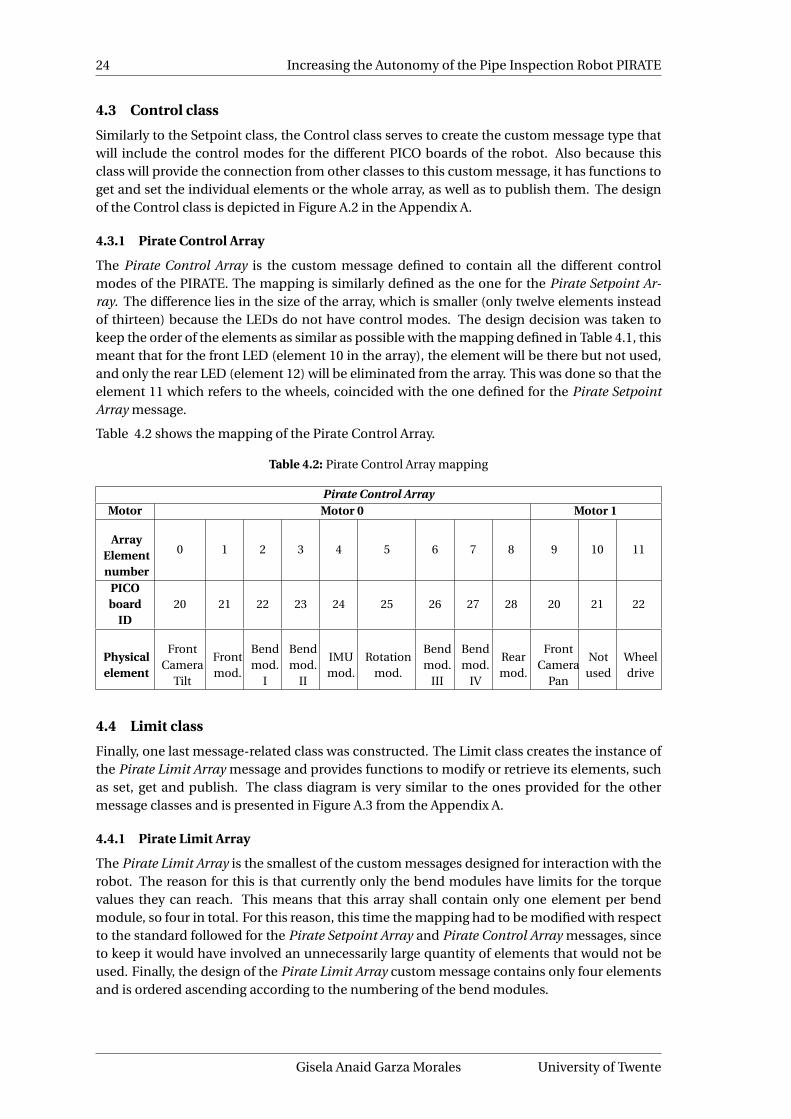
24 Increasing the Autonomy of the Pipe Inspection Robot PIRATE
4.3 Control class
Similarly to the Setpoint class, the Control class serves to create the custom message type thatwill include the control modes for the different PICO boards of the robot. Also because thisclass will provide the connection from other classes to this custom message, it has functions toget and set the individual elements or the whole array, as well as to publish them. The designof the Control class is depicted in Figure A.2 in the Appendix A.
4.3.1 Pirate Control Array
The Pirate Control Array is the custom message defined to contain all the different controlmodes of the PIRATE. The mapping is similarly defined as the one for the Pirate Setpoint Ar-ray. The difference lies in the size of the array, which is smaller (only twelve elements insteadof thirteen) because the LEDs do not have control modes. The design decision was taken tokeep the order of the elements as similar as possible with the mapping defined in Table 4.1, thismeant that for the front LED (element 10 in the array), the element will be there but not used,and only the rear LED (element 12) will be eliminated from the array. This was done so that theelement 11 which refers to the wheels, coincided with the one defined for the Pirate SetpointArray message.
Table 4.2 shows the mapping of the Pirate Control Array.
Table 4.2: Pirate Control Array mapping
Pirate Control ArrayMotor Motor 0 Motor 1
ArrayElementnumber
0 1 2 3 4 5 6 7 8 9 10 11
PICOboard
ID20 21 22 23 24 25 26 27 28 20 21 22
Physicalelement
FrontCamera
Tilt
Frontmod.
Bendmod.
I
Bendmod.
II
IMUmod.
Rotationmod.
Bendmod.
III
Bendmod.
IV
Rearmod.
FrontCamera
Pan
Notused
Wheeldrive
4.4 Limit class
Finally, one last message-related class was constructed. The Limit class creates the instance ofthe Pirate Limit Array message and provides functions to modify or retrieve its elements, suchas set, get and publish. The class diagram is very similar to the ones provided for the othermessage classes and is presented in Figure A.3 from the Appendix A.
4.4.1 Pirate Limit Array
The Pirate Limit Array is the smallest of the custom messages designed for interaction with therobot. The reason for this is that currently only the bend modules have limits for the torquevalues they can reach. This means that this array shall contain only one element per bendmodule, so four in total. For this reason, this time the mapping had to be modified with respectto the standard followed for the Pirate Setpoint Array and Pirate Control Array messages, sinceto keep it would have involved an unnecessarily large quantity of elements that would not beused. Finally, the design of the Pirate Limit Array custom message contains only four elementsand is ordered ascending according to the numbering of the bend modules.
Gisela Anaid Garza Morales University of Twente

CHAPTER 4. SOFTWARE FRAMEWORK DESIGN 25
Table 4.3: Pirate Control Array mapping
Pirate Limit ArrayMotor Motor 0
Array Element number 0 1 2 3PICO board ID 22 23 26 27
Physical element Bend mod. I Bend mod. II Bend mod. III Bend mod. IV
4.5 Pirate Manager class
This is the centralized class that manages the other nested classes’ creation. The reason for theexistence of such a class is based on the constraint that the messages which would be sent tothe robot required unification throughout the different levels of software as well as consistencyeven when changed from manual to PAB mode and viceversa. To obtain this desired centraliza-tion, a main container class was implemented. This approach provides a layered class structurewhere the manager creates an instance of the next level of classes and so on (i.e. composition).In the main node where the instances of the Setpoint, Control and Limit classes are created,the instance of the Pirate Manager class is generated too. The constructor of this class, takes asinput a reference to each of the message-related classes. This references are later distributedthroughout all the nested classes that are created within the Pirate Manager. At the next nestinglevel, it is possible to see in Figure 4.1 that inside the Pirate Manager two classes are created:the Mapper and the Pirate Server. The Pirate Manager class is shown in Figure A.4 from theAppendix A.
4.6 Mapper Class
The Mapper class has the dual function of handling the manual mode commands as well as,in case of Partially Autonomous mode, sending out PAB instructions to Pirate Server. The con-structor of this class takes references to the message-related classes, namely Setpoint, Controland Limit. This is done so that it has access to all the public functions to set, get and publishthe messages. From the client-server model between the Mapper and the Pirate Server, the firstone serves the purpose of being the client, thus it requests the resources of the Pirate Server forthe PAB execution.
Inside the Mapper class (for reference see Figure A.5 in the Appendix A), the client is createdand the subscribers and publishers for the user interface topics will be generated as well (topublish to UI driver output and subscribe to UI driver input). The Mapper is able to send com-mands to change the status of the LEDs in the user interface. This is used, for example, to lighton the button when the operation mode is PAB and turn it off when it is Manual it is directly vis-ible, and also to distinguish when the control mode of the modules is PWM/Torque/Position(depending on the module type), etc. Furthermore, the goal variable is declared, along withthe current operating mode variables, which will be used to control the permissions for eachof the modes. Finally, the map member function will check if there are new setpoints, controlmodes or limits sent by the user, and if this is the case, it will update the message-related classreferences. Outside this, in the publisher function, the publishing commands to the message-related classes will be sent. In the case of the control messages, because we want immediateaction for when they change, they are published as they are received inside the map function.The situation is different for the setpoints and limits, due to the fact that they are inputted fromsliders and knobs in the user interface, which generate a lot of unnecessary intermediate val-ues. Because of this and to avoid saturating the communication with the Arduino, these typeof messages will only be published every 10H z, which is a reasonable rate considering that therobust communication between the Arduino Mega and the robot, has an approximately similarrate, so there is no need to be publishing faster than that.
Robotics and Mechatronics Gisela Anaid Garza Morales

26 Increasing the Autonomy of the Pipe Inspection Robot PIRATE
Inside the map function, some of the inputs of the user interface will be used to send goals tothe Pirate Server, when in PAB mode. Because of this, the Mapper has the possibility to requestthe status of the server and to store it in a variable (activeGoal), which is checked before sendinga goal. If there is an active goal the Mapper will notify the user that it is not possible to send anew goal until the current one is completed or canceled. In this way, the program makes surethat if the user wants to send another goal, the current one must be canceled first.
4.7 Pirate Server class
The Pirate Server is in charge of handling (executing, aborting or preempting) the commandsthat the Mapper sends. Given the fact that it has to deal with very diverse partially autonomousbehaviors (PABs) execution, its architecture is complex. This resulted in a composite class thatuses the services of child classes, namely the Motion Primitives class and a class for each of thePABs that are required. In our case, only one of the PABs will be implemented, only one otherclass, the Clamp Straight, will be a child to the Pirate Server. More details on the Pirate Serverclass can be found Figure A.6 of the Appendix A. This composite class structure, provides theflexibility of adding more PABs by creating separate classes as desired. If this happens, onlyminor changes are required in the Pirate Server (to handle the request of the new PAB itself)and in the Mapper (to link the user interface command to send a new goal according to thenew PAB).
It is important to notice that, apart from the child classes, once again the message-relatedclasses (Setpoint, Control and Limit) are present as references. Inside the Pirate Server, thecorresponding goal and its feedback, result and status variables will be created, which will beused to exchange information with the Mapper. These messages will be discussed in length inSubsection 4.7.1.
In general, the Pirate Server has its own internal state machine, where the states are mappedto a structure called state_ (for reference see Figure A.6). This state machine keeps track of PABbeing executed. The internal state machine of the Pirate Server can be seen in Figure 4.2.
Here we see the six main PABs (in green) that have been discussed in Section 1.3. The PABrepresent, of course, temporal or transition states, which are active for a determined amount oftime (for example, the time it takes to clamp straight, etc). When those states finish, they reacha so-called idle state (in white), where the robot doesn’t produce any action, but rather waitsuntil another command is received.
As previously expressed, the relationship between the Mapper and the Pirate Server class, isbased on the client-server model. In order to communicate, the Mapper and the Server shouldshare messages that contain the relevant information about the action that will be executed. Inthe subsection 4.7.1, the messages exchanged between the Mapper and the Pirate Server willbe described in more detail.
4.7.1 Client-Server messages
In order for the server to start a PAB, the Mapper should send a message that contains whichPAB is desired along some additional parameters. Because all of this information relates to thedesired action, it will be referred to as the goal. Furthermore, according to the requirementsmentioned in Section 3.4, it is necessary also that the Mapper can send a message to cancel thecurrent goal on the Pirate Server. On the other hand, the server should send information backto the client, such as a result message, which should be sent at the end of a goal, a feedbackmessage, which, if required, could supply the client with intermediate status information onthe joint state of the robot, and finally a status message, which would be more general thanthe previous one, just presenting the current status of the goal itself (different from the jointinformation). The client-server model, is presented in Figure 4.3.
Gisela Anaid Garza Morales University of Twente

CHAPTER 4. SOFTWARE FRAMEWORK DESIGN 27
Idle Unclamped
Clamp StraightClamp Sideways
Idle ClampedTaking T-joint
Taking Mitre bend
Driving
Homing
PAB: Clamp StraightPAB: Clamp Sideways
Clamp Straight successfulClamp Sideways successful
PAB: Take T-joint
Take T-joint done
PAB: Take M. B.
Take M.B. done
PAB: Drive
Drive done
PAB
: Hom
e
PAB
:Hom
e
PAB
:Hom
e
PAB
:Hom
e
Hom
ing
succ
essf
ul
Figure 4.2: Internal state-machine of the Pirate Server
4.7.1.1 Goal definition
The goal has crucial information that the Mapper and Pirate Server require to function. It isbasically a custom message (structure) that contains the relevant fields for the server to executethe action. In our case, the definition has to be more on the side of what kind of action it is, andsome additional parameters to identify the possible options for each action. Since, in ROS, thegoal is defined in the same way as a custom message, a structure is created that contains thePAB’s name, the diameter of the pipe, and, depending on the PAB, additional parameters.
The description of the goal’s fields is as follows:
1. name: This will be used to uniquely identify the commanded PAB. Possible values arelisted in Table 4.4.
2. pipe diameter: This number indicates the diameter of the pipe in which the requestedPAB will be carried out. The diameter of the pipe is necessary for all the PABs, becauseit renders important information for the guards (conditions) that are needed during thesequence execution.
3. distance: This is an optional parameter to complement for the Drive PAB. This representsthe distance to drive and the sign defines the direction (positive- forward, negative- back-ward).
4. additional parameters: The design contemplated that this field can be used for the PABsthat require more information than the pipe diameter to execute. The foreseen values forthis field, depending on the PAB, are presented in Table 4.4.
Robotics and Mechatronics Gisela Anaid Garza Morales

28 Increasing the Autonomy of the Pipe Inspection Robot PIRATE
Mapper(Client)
goal
cancel
result
feedback
status
Pirate Server(Server)
Figure 4.3: Client-Server model and the interaction messages.
The design of the goals for each of the possible partially autonomous behaviors is described inTable 4.4.
Table 4.4: Goal messages for each PAB, with corresponding possible options
Client-Server - Goal definitionPAB Clamp straight Clamp sideways Home Take T-joint Take Mitre Bend Drive
nameCLAMP
STRAIGHTCLAMP
SIDEWAYSHOME T_JOINT MITRE_BEND DRIVE
pipe diameter (mm) 90/110* 90/110* N/A 90/110* 90/110* 90/110*
distance N/A N/A N/A N/A N/A
Range should bedetermined whenimplementing anddepending on the
test piping.Must be a signed
value, because directionwill be indicated with a sign.
additional options N/A(Suggested)Direction:Right/Left
N/A
(Suggested)Direction:Right/Left/Straight
(Suggested)Direction:Right/Left
N/A
* There are more diameters that the PIRATE can work with, but for the scope of this thesis, only the two
most common diameters are defined.
It is worth noting that from the PABs in Table 4.4, only the Clamp Straight will be implemented.However, the proposed suggestions might be a good place to start future implementations.
4.7.1.2 Result, feedback and status definition
The messages for the result, status and feedback are simpler than the goal because the infor-mation is sent as structures, and thus each of these messages contains only one structure.
Feedback: could provide the server with an asynchronous way to send periodic updates to theclient during the processing of a goal. Sending feedback is completely optional. In the presentdesign, the handling of the sensor’s feedback is done by either the Motion Primitives or the PABclasses. Because of this, the feedback message is currently not used.
Status: provides the client with status information about the goal that is currently being trackedby the server. The client uses this information to know if the goal is still active, aborted, etc.In this way, it can prevent the user from sending another goal while one is currently beingprocessed (which is explained in detail in Section 4.6).
A goal is tracked by the server until it reaches a terminal state. The status message has one field:
• goal state: contains the current goal’s status. The possible intermediate states are: ac-tive, pending and preempting (canceling). The terminal states are: rejected, succeeded,aborted and preempted (canceled).
Gisela Anaid Garza Morales University of Twente
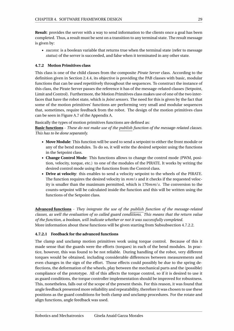
CHAPTER 4. SOFTWARE FRAMEWORK DESIGN 29
Result: provides the server with a way to send information to the clients once a goal has beencompleted. Thus, a result must be sent on a transition to any terminal state. The result messageis given by:
• success: is a boolean variable that returns true when the terminal state (refer to messagestatus) of the server is succeeded, and false when it terminated in any other state.
4.7.2 Motion Primitives class
This class is one of the child classes from the composite Pirate Server class. According to thedefinition given in Section 2.4.4, its objective is providing the PAB classes with basic, modularfunctions that can be used repetitively throughout the sequences. To construct the instance ofthis class, the Pirate Server passes the reference it has of the message-related classes (Setpoint,Limit and Control). Furthermore, the Motion Primitives class makes use of one of the two inter-faces that have the robot state, which is Joint sensors. The need for this is given by the fact thatsome of the motion primitives’ functions are performing very small and modular sequencesthat, sometimes, require feedback from the robot. The design of the motion primitives classcan be seen in Figure A.7 of the Appendix A.
Basically the types of motion primitives functions are defined as:Basic functions - These do not make use of the publish function of the message-related classes.This has to be done separately.
• Move Module: This function will be used to send a setpoint to either the front module orany of the bend modules. To do so, it will write the desired setpoint using the functionsin the Setpoint class.
• Change Control Mode: This functions allows to change the control mode (PWM, posi-tion, velocity, torque, etc.) to one of the modules of the PIRATE. It works by writing thedesired control mode using the functions from the Control class.
• Drive at velocity: this enables to send a velocity setpoint to the wheels of the PIRATE.The function requires the desired velocity in mm/s and it checks if the requested veloc-ity is smaller than the maximum permitted, which is 170mm/s. The conversion to thecounts-setpoint will be calculated inside the function and this will be written using thefunctions of the Setpoint class.
Advanced functions - They integrate the use of the publish function of the message-relatedclasses, as well the evaluation of so called guard conditions. This means that the return valueof the function, a boolean, will indicate whether or not it was successfully completed.More information about these functions will be given starting from Subsubsection 4.7.2.2.
4.7.2.1 Feedback for the advanced functions
The clamp and unclamp motion primitives work using torque control. Because of this itmade sense that the guards were the efforts (torques) in each of the bend modules. In prac-tice, however, this was found to be not reliable. During handling of the robot, very differenttorques would be obtained, including considerable differences between measurements andeven changes in the sign of the effort. Those effects could possibly be due to the spring de-flections, the deformation of the wheels, play between the mechanical parts and the (possible)compliance of the prototype. All of this affects the torque control, so if it is desired to use itas guard conditions, the torque controller implementation should be improved for robustness.This, nonetheless, falls out of the scope of the present thesis. For this reason, it was found thatangle feedback presented more reliability and repeatability, therefore it was chosen to use thesepositions as the guard conditions for both clamp and unclamp procedures. For the rotate andalign functions, angle feedback was used.
Robotics and Mechatronics Gisela Anaid Garza Morales

30 Increasing the Autonomy of the Pipe Inspection Robot PIRATE
4.7.2.2 Rotate
This motion primitive function allows to send a setpoint to the rotational module of the PI-RATE. The designed function requires as input the desired rotation in r adi ans. Inside thefunction it evaluates whether the requested value is within the limits, which are in the range of−0.7r ad to +0.7r ad from one part of the rotational module with respect to the other part. Theconversion to the counts-based setpoint will be calculated inside the function and this will bewritten using the functions of the Setpoint class.
As mentioned in Sub-subsection 2.4.1.4, the rotational module is formed by two parts con-nected by a motor, and which are capable of rotating with respect to each other. For the expla-nation of the rotation, we will divide the robot into two parts: front and rear (not to be confusedwith front and rear modules of the robot). These parts are shown in Figure 4.4.
Rear part Front part
Figure 4.4: Division of the PIRATE from the rotational module’s perspective
Normally, for the rotation procedure, either the front or the rear part of the robot will beclamped. This means that, for example, when the front part is clamped, the rear rotates andvice versa. It is important to notice that the sign in the setpoint of the rotation will indicatethe direction (clockwise or counterclockwise) of the module. This is, however, dependent onwhether it is the front or the rear part of the rotational module, the one that it is rotating. Ta-ble 4.5 shows the direction of the rotation with respect to the setpoint sign.
Table 4.5: Rotation direction according to setpoint sign
Sign of setpointDirection of rotation
Front clamped Rear clampedNegative Clockwise CounterclockwisePositive Counterclockwise Clockwise
As we can see in Table 4.5, the directions the same sign produces are opposite depending onthe part of the robot that will be rotating. The presented direction is taken from a front point ofview as depicted in Figure 4.5.
Clockwise
Counterclockwise
Figure 4.5: Rotation directions from front point of view
Gisela Anaid Garza Morales University of Twente

CHAPTER 4. SOFTWARE FRAMEWORK DESIGN 31
Since the rotate motion primitive is an advanced function, apart from publishing the setpoint,it includes the evaluation of whether or not the desired condition (guard) has been reached.The angle feedback of the rotational module is coming from a relative encoder, which at start-up is reset to zero value. This will be known as aligned condition and it will be further explainedin Sub-subsection 4.7.2.6. This makes possible to check if the rotation has been completedby actually checking whether or not the encoder’s feedback is equal (within an experimentaltolerance to be determined) to the desired rotation setpoint in radians.
4.7.2.3 Clamp rear / front parts
As mentioned in Sub-subsection 2.4.1.1, independent on the orientation of the robot, the con-figuration for clamping involves two of the bending modules forming a V-shape, which whenin contact with the pipe wall creates the so-called clamping force. In the Motion Primitives, wewill define as clamp front the one formed between the Bend Modules I and II, and clamp rearas the one formed between Bend Modules III and IV.
The clamp rear or front motion primitive considers that the involved bend modules are intorque control mode. Then, according to the supplied pipe diameter argument, it sends thenecessary setpoints to be able to clamp (either the rear or the front part of the robot). For this,the definitions of rear and front part of the PIRATE (from Figure 4.4) are applied again. Fig-ure 4.6, shows the result of the clamp rear and clamp front motion primitives.
Rear clamp Front clamp
α α
β β
γφ θ
Figure 4.6: Illustration of both clamp front and clamp rear as well as all the angles used in the PIRATE
The function returns success only if the robot state indicates it has been clamped. To know this,the angles of each of the bend modules are evaluated, as shown in Figure 4.6. Once these angles(referred to as guards) are reached (ang l eBend IV ,I ≈ α and ang l eBend I I ,I I I ≈ β), the functionsends a zero setpoint to the Bend Module III or Bend Module II in the case of rear and frontclamp, respectively. This is done to release some of the torque in these modules. If this weren’tdone, the torque would make it very hard (and sometimes impossible) to clamp or unclamp theremaining part of the PIRATE. Another important detail that the sequence takes into account ismoving the front module (represented by angle γ). The rotational angle might be used in caseorientation adjustment is required and is represented in Figure 4.6 as θ.
4.7.2.4 Custom clamp of rear / front parts
The services provided in the custom functions are similar to the ones described in Sub-subsection 4.7.2.3, with the difference that the guards to consider a successful clamping proce-dure can be customized and thus are part of the input arguments of the function. The reasonfor the creation of such customizable functions lies in the fact that they will be used when afull clamp cannot be performed. We refer to as full clamp as the one that can be performedin positions straight or sideways, i.e. in the points where the robot can reach the full diameterof the pipe (i.e. where previous guards defined as α and β can be reached). For the non-ideal
Robotics and Mechatronics Gisela Anaid Garza Morales

32 Increasing the Autonomy of the Pipe Inspection Robot PIRATE
situations, where the robot will have to get up from a side position, sometimes this full clampcannot be completed, and thus different guards are needed.
4.7.2.5 Unclamp and partial unclamp of rear / front parts
Unclamping can be thought of as the opposite action of clamping, which basically means thatinstead of moving the bend modules so that they form a V-shape, they are moved towards aposition where they form a straight line. There ar two variations for the unclamp which are:
1. Full: The outcome of this function is that the concerned modules (Bend I and II or BendIII and IV), independent of the robot orientation are in a complete straight line. Becauseof this, the guards will be equivalent to having α≈ 0r ad and β≈ 0r ad .
2. Partial: The procedure is similar to the full one, however the guards in this case aregreater than 0r ad , which means that the robot is unclamped, but the modules are notforming a straight line but rather a very open V-shape.
In the same manner, the guards for the successful completion of these routines consist onchecking both α and β angles to be consistent with the desired value. This condition will nothave to be changed depending on the pipe diameter, because it is designed for one of the small-est ones, 90mm. Because of this, in the other diameters the same guard will be more thanenough.
4.7.2.6 Align rear and front part
This function serves the purpose of counteracting the effects generated by the rotate function.In this last one, we look to generate a relative angle between the front and rear part of the robot(θ). In the align routine, this relative angle is brought close to zero radians (within a toleranceto be defined in the implementation). This function is required because only the rear part ofthe robot has the IMU sensor information, so without alignment it is a good way to locate and"home" the front part.
4.7.3 Error handling - Timeout for Motion Primitives Advanced functions
Finally, all the advanced motion primitive functions, being that they continuously evaluatewhether or not their condition for success has been reached, include a timeout, which serves asan error handling method. The functions receive a configurable timeout in seconds. If at anypoint the sequence is not completed before the timeout, this will trigger an error and a mes-sage for the user so that it can check the robot. Normally if the timeout is reached, it indicatesthat the robot has met an obstacle (or presents a mechanical failure, but this is less likely). Atthe currently developed stage of autonomy, and for the scope of this thesis, only this type oferror handling will be considered. In the future, such a response can be sent to a more abstractcontrol software layer (Supervisory) that can evaluate the error and act accordingly.
4.7.4 Partially Autonomous Behaviors (PABs) classes
As it has been mentioned, the software framework will integrate programmed sequences thatare able to perform basic tasks of the PIRATE. These basic tasks have to be carefully delimitedand are referred to as Partially Autonomous Behaviors. For the purposes of this report they aredefined as:
an action that performs a specific simple functionality of the robot. It consists of a sequence ofmotion primitives (simplest motion commands) and is able to cope with the most basic types ofdisturbances for each. By itself, it does not make the robot autonomous but together constitutes
the base for more complex (fully) autonomous behavior.
Gisela Anaid Garza Morales University of Twente

CHAPTER 4. SOFTWARE FRAMEWORK DESIGN 33
Keeping this definition in mind, and based on [1], the basic partially autonomous behaviors forthe PIRATE are defined (according to the orientation shown in Figure 4.7) as:
1. Clamp Straight: Movement of the robot where two V-shapes (upside down) are formedbetween modules Bend III and IV and Bend I and II, respectively. The orientation of therobot shall be π/2 radians from the base of the pipe (bottom). For reference see Fig-ure 4.7.
2. Clamp Sideways: Just as the other clamp this involves two V-shapes (upside down)formed between modules Bend III and IV and Bend I and II, respectively. The differ-ence lays in the orientation of the robot which could be either 0 radians (sideways-right)or π radians (sideways-left).For reference see Figure 4.7.
3. Drive: This action allows the robot to navigate inside a pipe. The precondition to this isthat the robot must be clamped (in any of the possible forms) for better stability. As aproposition, to use this PAB the user must supply a desired distance in mm to drive. Thedistance value should include a sign to indicate the direction of the drive (negative sign -drive backwards).
4. Take Mitre-Bend (for short referred as Mitre-bend): it is one of the complex PABs. Itrequires a long sequence where the robot must start clamped, then detect when the frontpart loses traction (entering the T-joint), unclamp and rotate according to the desireddirection to take and reclamp the front part of the robot (Bend I and II). This processhas to be repeated so that the rear part of the robot (after the rotational module) passthe bend in the same fashion. Depending on the direction desired (left or right) andthe orientation of the bend itself, the clamping required beforehand could be straight orsideways (left or right).
5. Take T-joint (for short referred as T-joint): Has the same description as the mitre-bend.Nonetheless, compared to the Mitre bend, an added complexity for the sequence is theopen side of the T-joint with which no contact is possible.
6. Home (unclamp): this routine shall bring the PIRATE to a resting position on the bottomof the pipe. The orientation of the robot in this case will be π/2 radians.
0 radπ rad
π2 rad
3π2 rad
Figure 4.7: General orientation of the PIRATE in radians used in the design
Due to the time constraint for this project only one of the partially autonomous behaviors shallbe fully designed and implemented in software using a state machine architecture, which willbe the clamp straight. This should yield a proof of concept of the developed software frame-
Robotics and Mechatronics Gisela Anaid Garza Morales
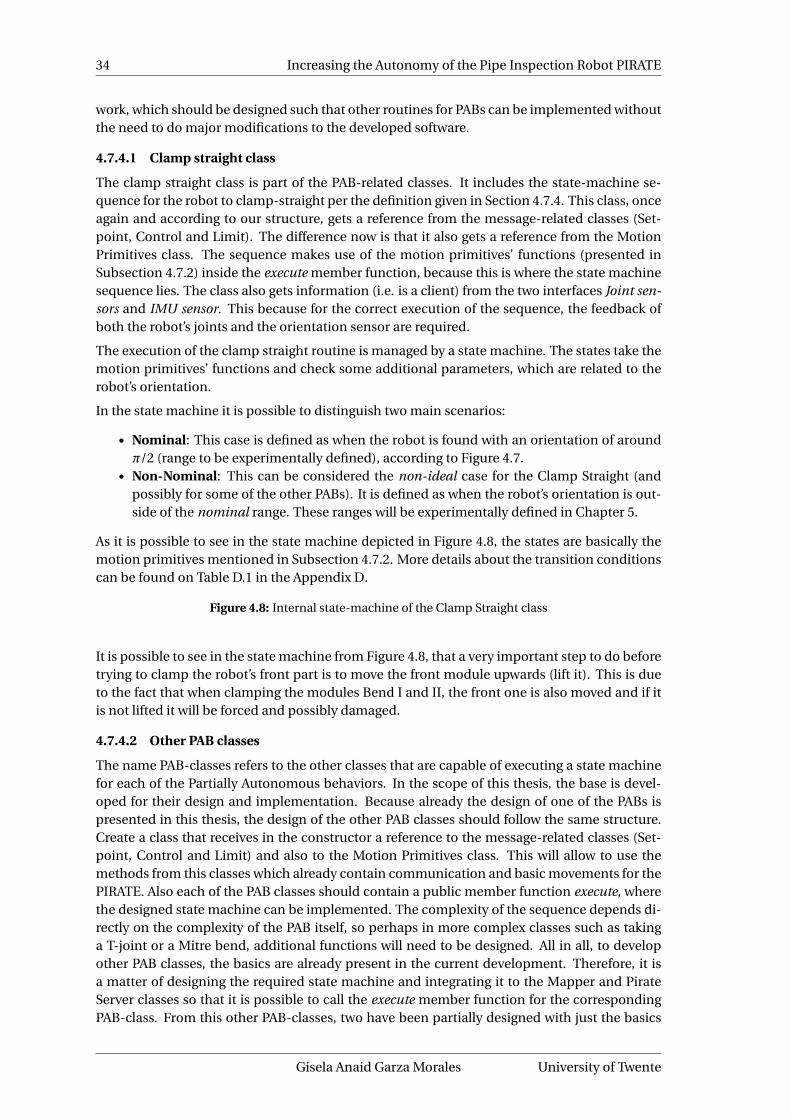
34 Increasing the Autonomy of the Pipe Inspection Robot PIRATE
work, which should be designed such that other routines for PABs can be implemented withoutthe need to do major modifications to the developed software.
4.7.4.1 Clamp straight class
The clamp straight class is part of the PAB-related classes. It includes the state-machine se-quence for the robot to clamp-straight per the definition given in Section 4.7.4. This class, onceagain and according to our structure, gets a reference from the message-related classes (Set-point, Control and Limit). The difference now is that it also gets a reference from the MotionPrimitives class. The sequence makes use of the motion primitives’ functions (presented inSubsection 4.7.2) inside the execute member function, because this is where the state machinesequence lies. The class also gets information (i.e. is a client) from the two interfaces Joint sen-sors and IMU sensor. This because for the correct execution of the sequence, the feedback ofboth the robot’s joints and the orientation sensor are required.
The execution of the clamp straight routine is managed by a state machine. The states take themotion primitives’ functions and check some additional parameters, which are related to therobot’s orientation.
In the state machine it is possible to distinguish two main scenarios:
• Nominal: This case is defined as when the robot is found with an orientation of aroundπ/2 (range to be experimentally defined), according to Figure 4.7.
• Non-Nominal: This can be considered the non-ideal case for the Clamp Straight (andpossibly for some of the other PABs). It is defined as when the robot’s orientation is out-side of the nominal range. These ranges will be experimentally defined in Chapter 5.
As it is possible to see in the state machine depicted in Figure 4.8, the states are basically themotion primitives mentioned in Subsection 4.7.2. More details about the transition conditionscan be found on Table D.1 in the Appendix D.
Figure 4.8: Internal state-machine of the Clamp Straight class
It is possible to see in the state machine from Figure 4.8, that a very important step to do beforetrying to clamp the robot’s front part is to move the front module upwards (lift it). This is dueto the fact that when clamping the modules Bend I and II, the front one is also moved and if itis not lifted it will be forced and possibly damaged.
4.7.4.2 Other PAB classes
The name PAB-classes refers to the other classes that are capable of executing a state machinefor each of the Partially Autonomous behaviors. In the scope of this thesis, the base is devel-oped for their design and implementation. Because already the design of one of the PABs ispresented in this thesis, the design of the other PAB classes should follow the same structure.Create a class that receives in the constructor a reference to the message-related classes (Set-point, Control and Limit) and also to the Motion Primitives class. This will allow to use themethods from this classes which already contain communication and basic movements for thePIRATE. Also each of the PAB classes should contain a public member function execute, wherethe designed state machine can be implemented. The complexity of the sequence depends di-rectly on the complexity of the PAB itself, so perhaps in more complex classes such as takinga T-joint or a Mitre bend, additional functions will need to be designed. All in all, to developother PAB classes, the basics are already present in the current development. Therefore, it isa matter of designing the required state machine and integrating it to the Mapper and PirateServer classes so that it is possible to call the execute member function for the correspondingPAB-class. From this other PAB-classes, two have been partially designed with just the basics
Gisela Anaid Garza Morales University of Twente

CHAPTER 4. SOFTWARE FRAMEWORK DESIGN 35
to show the possibilities of missions as a result of the present thesis. They are the Drive and theHome and both will be shortly described next.
4.7.4.2.1 Home classPer the definition, homing is the activity to unclamp the robot and leave it in a 0 radians orien-tation. The home class was developed to complement the Clamp Straight function and showthe potential of implementing other PAB classes and executing them sequentially for a mission.This, however, was only done basically and in no way is a comprehensive design of this behav-ior. This design can perform a simple state machine that can unclamp the PIRATE assumingthat is clamped at a straight position. The design of the class is based on the recommendationsfrom Subsubsection 4.7.4.2. Inside the execute member function lays the state machine for thebasic behavior of the homing. The class is shown in Figure A.9 from the Appendix A. The basicstate-machine developed only to test can be seen in Figure 4.9.
Change con-trol modes
Unclamping Front Unclamping Rear Moving Front
Figure 4.9: Basic Internal state-machine of the Home class assuming that the PIRATE starts in a straightposition
As it can be seen in Figure 4.9, the sequence is very basic and linear. In the future, proper designshould be done so that this function has the capability of detecting what the current orientationis and take the decisions to home the robot based on that.
4.7.4.2.2 DriveAs mentioned before, driving is the behavior that allows the robot to move throughout a pipe inboth forward and backward directions. The pre-condition as seen in Figure 4.2 is that the robotis clamped. The class design also follows the standard of the other PAB-classes and is shown inFigure A.10 from the Appendix A.
For the basic development this PAB only has one state: Driving. For future (complete) design,possible non-ideal situations should be taken into account (possible obstacle or getting a bitstuck), so this sequence can become more robust. This was made simple, because it is part ofthe demonstration mission, but a complete design is out of scope for this thesis.
4.8 Interfaces
The interfaces are designed based on the need to retrieve feedback information from the robot.Basically there is a main interface class that obtains the status of all the sensors of the robotcalled Pirate state. From this state the information is passed to other two interface classes,depending on the type of information, namely one for the joint status called Joint sensors andother for the orientation information of the robot called IMU sensor.
4.8.1 Pirate state interface
The Pirate State interface is the main connection from ROS to the robot’s hardware through theArduino Mega (Pirate Bay board). The goal of this interface is to retrieve the robot’s feedback(efforts, angles, velocity, odometry, etc.) for all the joints as well as the IMU sensor. The logicbehind this node was already implemented by Reiling, prior to the start of this thesis, how-ever, it was not using the publish-subscribe model from ROS. In the present design, the dataexchange is designed based on the ROS publishing and subscribing capabilities. In this waythe Pirate state class will subscribe to the topic published by the Arduino Mega. The details forthe implementation are discussed in Chapter 5.
Robotics and Mechatronics Gisela Anaid Garza Morales

36 Increasing the Autonomy of the Pipe Inspection Robot PIRATE
4.8.1.1 Pirate Small State message
Depending on the type of module that the PICO board is attached to, there are variations withrespect to which kind of feedback is obtained and sent to the Pirate state interface class. Ta-ble B.1 shows the feedback obtained from the Arduino Mega per PICO board.
As it is possible to see, the longest message, from PICO board 25, contains 9 elements. Thereason for this is that this board contains the message of the IMU sensor which serves in ourdesign to obtain the orientation of the robot. Because of this, a message was designed so thatthe Arduino Mega could publish the feedback in ROS and the Pirate state class could subscribeto it. It is important to mention that this was chosen to be sent per each PICO board and not asa "full" state, because of the limits of the amount of information exchange in the Arduino side.The design from Reiling (mentioned earlier) suggested that this was an efficient way to sendthe feedback from the robot.
This message to be exchanged as feedback per PICO board was named Pirate Small State andcontains an array of 9 elements. Details of the mapping of the Pirate State per PICO Board canbe found in Table B.1 from the Appendix B.
4.8.2 IMU and Joint sensor interfaces
The design of these two interfaces is based on the blackboard design pattern, which is used insoftware engineering, to coordinate separate, disparate systems that need to work together, orin sequence. The blackboard consists of a number of "global variables", like a repository ofmessages, in our case the robot state (namely IMU and Joint data), which can be accessed byseparate processes, such as the Motion Primitives class or the Clamp Straight (or any otherPAB). This was chosen over the traditional publish-subscriber approach from ROS, becauseeven though the robot status will be constantly received from the Arduino Mega, it is not neces-sary that it notifies the PAB or the Motion Primitives class every time this happens. This meansthat they do not require to be subscribed to all the feedback received, but rather request for itwhen they are performing a specific sequence and they need the sensor data to validate if theguard has been achieved. Figure 4.10 shows the communication between the IMU and Jointblackboards and the client classes.
Joint state Blackboard
IMU state Blackboard
Client class(Motion Primitives/PAB class)
response
request
response
request
Figure 4.10: Blackboard-like design for the IMU and Joint Sensors classes
4.8.3 User interface Drivers
The user interface drivers are two small ROS nodes that serve the purpose of communicatingROS with the user interface. In our case the selected interface device is a MIDI fader panel. Itwas chosen because of its native communication capabilities via USB and of the intuitive withwhich several modules can be commanded at a time.
In general, there are two kinds of drivers present in the design:
• Input driver: has the function of retrieving the inputs of the user interface and publishingthem to ROS.
Gisela Anaid Garza Morales University of Twente

CHAPTER 4. SOFTWARE FRAMEWORK DESIGN 37
• Output driver: has the function of subscribing to a the topic that sends the LED status forthe user interface (found in the Mapper class) and sending it via USB to the user interfacedevice.
4.8.3.1 User interface input and output messages
To make possible the communication through ROS topics, two simple messages were designedto send the input and output to the user interface. They are called MidiInput and MidiOutput.The elements of the messages are shown in Table 4.6.
Table 4.6: Midi Input and Output Messages
MidiInput MidiOutputchannel ID button ID
value boolean value
As it is possible to see, the input message has the channel ID which is a unique number thatidentifies the element of the fader panel that was activated and in this case it’s correspondingvalue. The output message only serves for the illumination of the LEDs so it only takes intoaccount the button’s ID (not all the channels) and the corresponding value is a boolean (on/off)value.
Robotics and Mechatronics Gisela Anaid Garza Morales

38 Increasing the Autonomy of the Pipe Inspection Robot PIRATE
5 Implementation
This chapter covers the implementation of the design described in Chapter 4. Based on this,first, we will introduce and describe the ROS packages or tools used for the implementationsof the communication, client-server models and blackboard design patterns. Next, the design’sfunctionality will be described based on the basic use cases. After that, more detail on theimplementation will be given of the most relevant classes, namely the Mapper, Pirate Server,Motion Primitives and Clamp Straight and Pirate State classes. Finally, pertinent informationabout the implementation of a simple test mission scenario, will be given.
5.1 Serial communication between Arduino Mega and ROS
As stated before the communication from ROS to the PIRATE will be implemented using the Ar-duino Mega as a transparent bridge. This microcontroller has 4 UARTs (hardware serial ports),from which one is currently used to establish the communication to/from the PICO boards.The development from Reiling, previous to the start of this thesis, had used one of the serialports to send the feedback information to ROS via serial commands. This implementation,however, did not make use of the publishing/subscribing capabilities of ROS and the readilyavailable resources for implementing serial communication with Arduino microcontroller asclient. Furthermore, in the original development by Reiling, the Arduino Mega was in directcommunication with the user interface. Because this was no longer the case (see Section 1.4),it was necessary to implement a way to send the setpoints, control modes and limits to the Ar-duino Mega via serial port. In the present work, the rosserial package was used to replace theexisting communication for the feedback (using the designed Small State message described inSub-subsection 4.8.1.1) and also to implement the ROS-side of the communication. Basicallyrosserial is a protocol for wrapping standard ROS serialized messages, topics and services overa character device such as a serial port or network socket.
The implementation of rosserial requires two parts:
• Serial Client: The client libraries allow to easily get ROS nodes up and running on varioussystems. Among the readily available supported libraries it is possible to find one for Ar-duino microcontrollers (called rosserial_arduino 1). In this way, the library is downloadedand installed to the Arduino development software and allows to use ROS publishers andsubscribers inside the microcontroller’s code.
• Serial Server / ROS-side interface: Is a node in the host machine that allows devices run-ning rosserial code to bridge the connection from the serial protocol to the more generalROS network. ROS already provides fully functional host nodes for the rosserial code.The one selected for our development is called rosserial_python 2, which is the most rec-ommended for PC usage.
Figure 5.1 shows the message exchange between the ROS network and the Arduino Mega us-ing rosserial. It is possible to see that the message-related classes serve as publishers for thecontrol, setpoint and limit messages for which the Arduino is a subscriber. Moreover, the mi-crocontroller publishes the Small state message which was discussed in Sub-subsection 4.8.1.1and that contains the feedback state of the robot per PICO Board ID.
1ROS.org - rosserial_arduino http://wiki.ros.org/rosserial_arduino2ROS.org - rosserial_python http://wiki.ros.org/rosserial_python
Gisela Anaid Garza Morales University of Twente

CHAPTER 5. IMPLEMENTATION 39
PC (ROS-side)rosserial host (rosserial_python)
Arduino Megarosserial client (rosserial_arduino)
Pirate Manager
Limit (class)
Control (class)
Setpoint (class)
Pirate State (class)
pirate/limits_array
pirate/control_array
pirate/setpoint_array
pirate/Small_State
Figure 5.1: Communication using rosserial between Arduino Mega and ROS
5.2 Actionlib from ROS
The actionlib 3 stack provides a standardized interface for interfacing with preemptable tasksin ROS. A preemptable task is one that can be canceled at any time, as per our requirements forthe PAB sequences.
The actionlib package provides tools to create the client-server model that we have designed asthe Mapper and the Pirate Server classes. The actionlib is composed of:
1. Action server: executes long-running goals that can be preempted. Since it is created in aseparate node, it is therefore thread-independent and thus non-blocking to the client.
2. Action client: provides an interface to send requests to the server.
Their implementation of the Action Server and Action Client might be tailored made usingthe full functionality of the actionlib package, however ROS does provide simple templates touse, called Simple Action Server and Simple Action Client. For the development presented inthis thesis, the level of descriptiveness provided by these simple templates was enough for ourdesired functionality.
Basically the client is in charge of sending goal or cancel requests, and the server, on the otherhand, handles the goal execution, providing the client with status, feedback and result. As itis possible to see, the definition of the actionlib package fits perfectly to our necessities andrequirements, so it was used for the implementation of both the Mapper and Server communi-cation structure.
5.3 ROS Services
For the implementation of the blackboard design pattern for the IMU and Joint sensor classeswe will use ROS services. The reason not to use the publisher/subscriber scheme of ROS wasdiscussed in Subsection 4.8.2, but it is mainly based in the fact that the Motion Primitives andthe Clamp Straight classes need to get the robot state information at specific time during thesequence, which means that a request/reply model is more appropriate. This type of commu-nication pattern is done via a service, which is defined by a pair of messages: one for the requestand one for the reply. A providing ROS node offers a service under a string name, and a clientcalls the service by sending the request message and awaiting the reply. Client libraries usuallypresent this interaction as if it were a remote procedure call. When doing the implementationof the system, the necessity raised for several classes, namely the Clamp Straight class and theMotion Primitives class, to be able to request for the server status, to know if it had been pre-empted. The easiest way to achieve this was to include a service server inside the Pirate Server
3ROS.org - Actionlib Detailed Description http://wiki.ros.org/actionlib/DetailedDescription
Robotics and Mechatronics Gisela Anaid Garza Morales

40 Increasing the Autonomy of the Pipe Inspection Robot PIRATE
class. In this way, the both Clamp Straight and Motion Primitives can periodically ask duringtheir loops for the status of the server. If it has been preempted they will stop their functions,as it is expected after cancellation of a goal.
5.3.1 IMU and Joint service messages
Like topics, services have an associated service type that depends on the desired type of re-quest and response. In all of our cases, the request can be empty since the response of theservice does not depend on any particular argument to be supplied. Furthermore the responseof the service can vary depending on the required feedback. Table 5.1 shows the informationcontained in the response of the implemented services.
Table 5.1: Type of responses for the implemented services
Service ResposeIMU sensor Roll, pitch and yaw
Joint sensors Position and effort of each joint (module)Pirate Server status Active / Cancelled
5.4 User interface drivers
For the user interface two nodes were implemented in Python using the online available re-source called pygame.midi4. One node is for communication from the current user interface(i.e. a MIDI fader panel - input driver) to ROS and the other to deliver messages from ROS tothe panel (in this case, to turn on the LEDs of the buttons as feedback - output driver).
5.5 Use Cases
As mentioned in Subsection 2.2.2, use cases are a good way of showing the functionality of thesoftware system. In Figure 5.2 the Main Use Case (Pirate) diagram, which describes the mostrelevant functions for this development, is shown.
PiratePirate
Select mode of operation
Send manual command
Send Partially Autonomous command
Cancel Partially Autonomous command
User PIRATE Robot
Figure 5.2: Main Use Case Diagram for the PIRATE.
It is possible to see that the main use case is composed of four use cases, which show the mainfunctionalities of the PIRATE. Each of these will be briefly described below.
4pygame Midi - Documentation http://www.pygame.org/docs/ref/midi.html
Gisela Anaid Garza Morales University of Twente

CHAPTER 5. IMPLEMENTATION 41
5.5.1 Select mode of operation
A robot can operate in different ways depending on the application. The simplest way to definean operation mode is as:
a way or manner in which the robot does a certain action and how it interacts with the user
In our case, the present work develops two possible modes of operation for the PIRATE:
1. Manual mode: Mode in which the operator must trigger and intervene at each instant inorder for the robot to execute an action.
2. Partially Autonomous mode: Mode in which the user has the possibility to trigger (pre-programmed) partially autonomous behaviors (PABs). It is considered partially (and notfully) autonomous because, for this robot, there is still possibility to build more abstractsoftware levels that can handle more complex mission-planned routines as well as copewith more diversity of disturbances.
The precondition for this use case consists on the robot being in "stop" state (i.e. when theuser interface is stopped). Furthermore the default start-up condition for the robot is manualoperation. In order to change the mode of operation of the robot one of the unused buttonsof the MIDI panel has been chosen. The selected button is the REWIND, as it can be seen inTable E.1 in Appendix E. According to the implementation, if the button is pressed once it willchange the mode from PAB to Manual, this will turn on the LED in the button, as an indicationof the fact that the system is in PAB mode. If the user presses the button once more, the modewill be reverted to manual, and the LED will turn off. This was designed so that in the future,when other available buttons are required to trigger the PAB sequences, there is availability. Ascomplement to this information, Figure 5.3 shows a diagram for this use case.
Figure 5.3: Diagram for "Select Mode of Operation" use case.
The change of operation mode is also shown as feedback in the main ROS screen, which can befound in Figure C.1 from Appendix C.
Robotics and Mechatronics Gisela Anaid Garza Morales

42 Increasing the Autonomy of the Pipe Inspection Robot PIRATE
5.5.2 Send manual command
This use is executed when the system is in Manual operation mode. The user interface (cur-rently MIDI panel) has the mapping for all the different modules, limits, control modes, cam-eras, LEDs, etc. This mapping to the MIDI panel is shown in the Appendix E. According to thevalue inputted in the UI, the Mapper will generate the setpoints and send them to the ArduinoMEGA. This is shown in detail in the diagram from Figure 5.4. How the Mapper class does thiswill be described later in Section 5.7.
Figure 5.4: Diagram for "Send manual command" use case.
5.5.3 Send PAB command
As mentioned before, the manual commands are mapped to several buttons, sliders and knobsin the user interface. A few of these buttons don’t work for manual operations, but serve totrigger PAB sequences when the operation mode of the system is PAB. Figure 5.5 shows thefunctionality of this use case.
As it is possible to see, most of the designed classes from Chapter 4, are used during a PABcommand execution. Figure 5.5 shows the interaction of all the designed classes in a normalflow of sending a PAB command. In the end, it is possible to see two outcome states, namelythe Aborted (when timed-out) and the Succeeded. There is one additional possibility which isPreempted (Canceled) and this will be discussed next. Besides the PAB commands, the diagramin Figure 5.5 shows that if an allowed manual command (moving cameras, turning on LEDs,etc.) is sent while in PAB mode, it will be executed, as if it were on Manual mode. It is worthnoting that the Mapper’s and Pirate Server’s implementation is done in independent nodes andthey both work in a non-blocking way. This means that if the Mapper first received a "ClampStraight" PAB command, once it has requested it to the Pirate Server, it can keep listening toother commands. The condition not to send a new goal when another one is being executed
Gisela Anaid Garza Morales University of Twente

CHAPTER 5. IMPLEMENTATION 43
is in the "goal currently executing?" condition. If there is one running, the new PAB commandwill not execute, and the user will be alerted.
Figure 5.5: Diagram for "Send PAB command" use case.
Robotics and Mechatronics Gisela Anaid Garza Morales
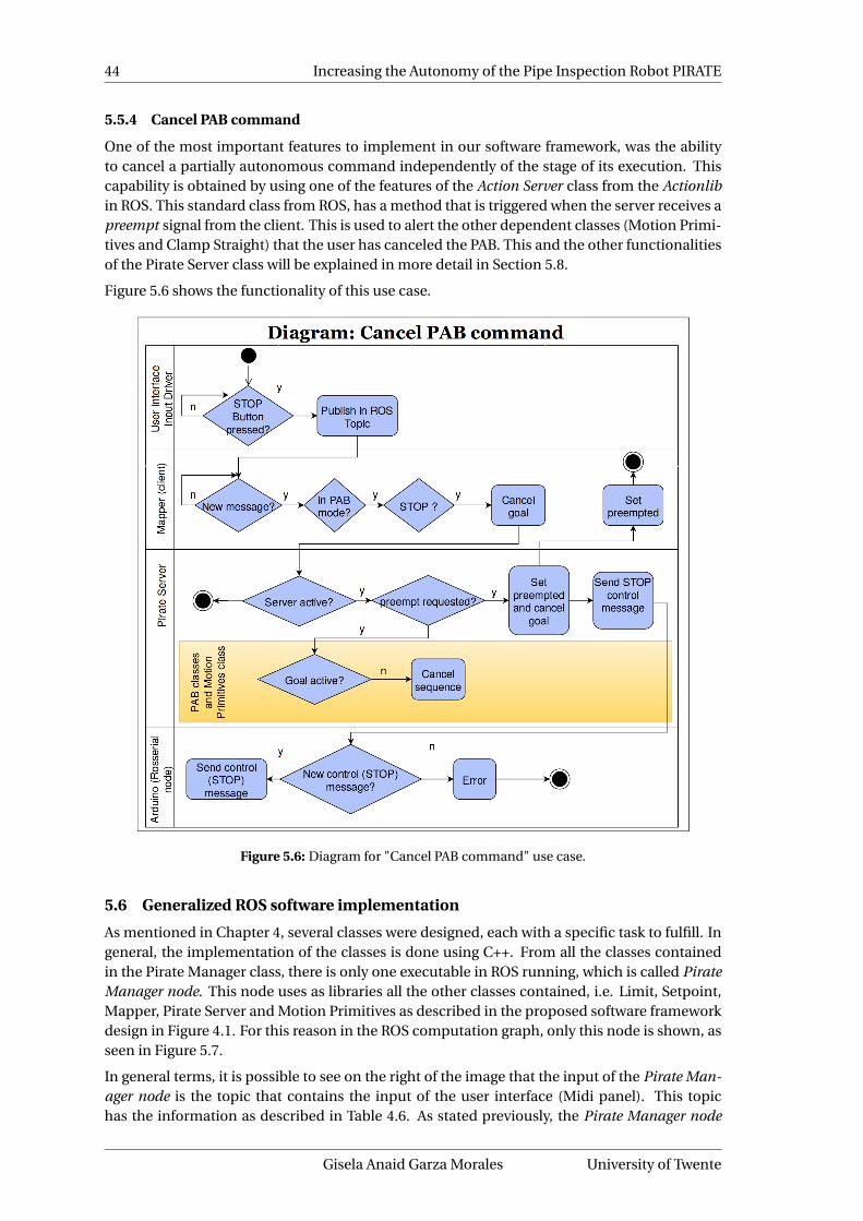
44 Increasing the Autonomy of the Pipe Inspection Robot PIRATE
5.5.4 Cancel PAB command
One of the most important features to implement in our software framework, was the abilityto cancel a partially autonomous command independently of the stage of its execution. Thiscapability is obtained by using one of the features of the Action Server class from the Actionlibin ROS. This standard class from ROS, has a method that is triggered when the server receives apreempt signal from the client. This is used to alert the other dependent classes (Motion Primi-tives and Clamp Straight) that the user has canceled the PAB. This and the other functionalitiesof the Pirate Server class will be explained in more detail in Section 5.8.
Figure 5.6 shows the functionality of this use case.
Figure 5.6: Diagram for "Cancel PAB command" use case.
5.6 Generalized ROS software implementation
As mentioned in Chapter 4, several classes were designed, each with a specific task to fulfill. Ingeneral, the implementation of the classes is done using C++. From all the classes containedin the Pirate Manager class, there is only one executable in ROS running, which is called PirateManager node. This node uses as libraries all the other classes contained, i.e. Limit, Setpoint,Mapper, Pirate Server and Motion Primitives as described in the proposed software frameworkdesign in Figure 4.1. For this reason in the ROS computation graph, only this node is shown, asseen in Figure 5.7.
In general terms, it is possible to see on the right of the image that the input of the Pirate Man-ager node is the topic that contains the input of the user interface (Midi panel). This topichas the information as described in Table 4.6. As stated previously, the Pirate Manager node
Gisela Anaid Garza Morales University of Twente

CHAPTER 5. IMPLEMENTATION 45
Figure 5.7: ROS computation graph for the developed software framework.
Robotics and Mechatronics Gisela Anaid Garza Morales

46 Increasing the Autonomy of the Pipe Inspection Robot PIRATE
is the instance of the centralized class Pirate Manager, this is the one that interconnects mostof the other topics. As outputs of the node, are the message-related topics for the setpoint,control modes and limits. Furthermore, the action topics are shown grouped together and therelationship is both coming in and out of the pirate manager node. This can be explained, asmentioned before, due to the fact that it contains inside both the Mapper and the Server, whichexchange information (goal, status, result, etc.) through these topics. More towards the centerthe serial node can be observed. This is generated using the rosserial interface. The serial nodereceives the information by subscribing to the message related topics. In this way, the Arduino(which is the client to the rosserial) receives this information when it is published and updatesthe robot accordingly. Besides receiving the setpoint, control mode and limit commands theserial node publishes the Small State message discussed in Sub-subsection 4.8.1.1, which con-tains the feedback of the robot’s status.
On the other side of the graph, the Pirate State node is found. This node subscribes to the SmallState topic thus it gets the feedback for each PICO board in the robot. Then it distributes it to theimplemented services, separating it in the joint service (whose node is called jointsrv_server)for the feedback of the joints and the IMU service (called imu_rpy node) for the orientationstatus. From the joint state obtained in the Pirate State node, a Robot publisher is created touse in an rviz node for the visualization. The visualization part was implemented by Reiling,during the year prior to the start of this thesis.
Finally the implementation of the communication with the user interface can be found in thelower right corner. The topics are /ram/input/midi and /ram/input/midiout, for the input andoutput to the Midi panel, respectively. It is possible to see that this topics enter the pirate man-ager node because inside it they are handled by the Mapper class.
5.7 Mapper class implementation
As mentioned in Section 4.6, one of the functions of the Mapper is to keep track of the operationmodes, as described in the use case from Subsection 5.5.1. The feedback screen for changingthe operation mode is shown in Figure C.1 in the Appendix C.
The Mapper class’ main function is to translate the user interface commands. This is doneby subscribing to the topic published by the User Interface Input driver node. In ROS, a sub-scription uses a callback function to handle whenever new data has been published. The gen-eral implementation of this callback function (named map) is based on a switch case structurewhich is shown in Figure 5.8.
Figure 5.8: Generalized implementation of the callback function in Mapper class
Gisela Anaid Garza Morales University of Twente

CHAPTER 5. IMPLEMENTATION 47
In Figure 5.8 it is possible to see the different cases numbered between 0 and 70, this is becausethose are the channel numbers that are sent (according to Table E.1). These numbers comedirectly from the manufacturer of the Midi fader panel and are shown in the Appendix E. Thestatement "case X actions" in Figure 5.8, refers to the setpoint/control mode/ limit generationfrom the raw Midi value obtained from the topic. This translation was designed originally byReiling and is the same that used to be implemented in the Arduino Mega software, before thestart of this thesis.
Previous development only included manual commands, nevertheless, the current implemen-tation of the Mapper includes now the possibility to act as a Client from the Actionlib packagein ROS. To do so an instance of the Simple Action Client is created inside the Mapper class. TheSimple Action Client contains ready to use member functions such as the ones for sending thegoal to the server, canceling it, etc. In the example shown in Figure 5.8, it is possible to noticethat case 58 corresponds to one of the buttons that triggers a PAB command. Inside this case’sstatements the goal parameters are configured according to what was discussed in Table 4.4and the goal is sent. To cancel a goal, if one is active and the system is in PAB operation mode,then the STOP button cancels the sequence, just like in manual operation mode it would stopthe motion.
5.8 Pirate Server class implementation
As we know from Section 4.7, the server handles the execution, tracking and preempting of thegoals. The way it does this is by using an instance of the Simple Action Server class from theROS Actionlib. This class offers some readily available functions (such as the one to preempta goal). It is also important to notice that this supplied class of the Actionlib from ROS has aninternal state machine (not to be confused with the state machine of the Pirate Server classitself, shown in Figure 4.2). The end states of this state machine can be Succeeded, Aborted orPreempted. The call for the PAB sequence is processed in the member function execute, wherealso a switch-case structure is implemented. A basic representation of the execute memberfunction of the Pirate Server class is depicted in Figure 5.9.
Figure 5.9: Generalized implementation of the execute member function in Pirate Server class
In Figure 5.9, it is possible to see that inside each of the cases, the member function execute ofeach of the PAB-classes will be called and, in case it is needed, the parameters will be passed.If the execute method of the corresponding PAB class returns a success value, then the serverwill set its internal state to Succeeded, when something went wrong the return value of the PAB
Robotics and Mechatronics Gisela Anaid Garza Morales

48 Increasing the Autonomy of the Pipe Inspection Robot PIRATE
execute method will be false (not succeeded) which will send the internal state machine of theSimple Action Client to a Aborted state. This state is presented when, for example, the modulesdidn’t respond during clamping and the sequence timed-out. At start-up in the feedback screenit is shown that the Pirate Manager, the Mapper, the Server and all the component classes arebeing constructed. This is depicted in Figure C.2 from the Appendix C.
Furthermore, the preempting process, as mentioned before, is handled by the supplied func-tion of the Simple Action Server class (called setPreempted). This callback function will becalled whenever the server receives a cancel goal command. In this way the status of the in-ternal state machine of the Simple Action Server instance will change to preempted. This willtrigger the dependent classes, in our implementation, Motion Primitives and Clamp Straight(and other PAB classes) to stop their functions as well. The feedback screen from this situationis shown in Figure C.3 from the Appendix C.
5.9 Motion Primitives class implementation
As discussed in Subsubsection 4.7.2.1, the first choice for the guards for the clamping and un-clamping functions was the effort feedback. However, during design testing as well as through-out the implementation, the torque measurements obtained from the robot were inconsistentand thus did not provide a suitable guard option. This might be possible to correct by improv-ing the robustness of torque control implementation in the PICO boards, however this was outof the scope for the present thesis. This can be observed in the torque results from Chapter 6.Because of this lack of repeatability, it was decided to use only angle feedback for all the ad-vanced motion primitives as well as for the implementations in the PAB classes. Due to thefact that in the design stage of the Motion Primitive class, presented in Section 2.4.4, most ofthe functionality of the member functions was already discussed at length, in this section wewill add the guards values obtained experimentally. The guard values are used inside the rou-tines that have feedback, referred to as the Advanced routines, such as clamp front/rear, un-clamping (full and partial versions) and align. Due to the limited time for the present work, theimplementation was focused on the 90mm and 110mm pipes (this last one only for a nominalcase). The guards for the relevant motion primitives are presented in Table 5.2. It is impor-tant to mention that all the guards used are angles because during the implementation thetorque measurements were not so constant and the most repeatability was found when usingthe guards with angles instead of torques. In this way by supplying the diameter of the pipe,it is possible to know what angles to expect when the PIRATE has been clamped, when it hasunclamped, etc. This is also the case for the guards implemented in the Clamp Straight class,which will be discussed next.
Table 5.2: Guard values used in the implementation of the Motion Primitives class
Motion Primitive Module AngleSetpoint(counts)
Guards (in radians)Pipe diameter
90mm 110mm
Clamp Rear / FrontBend Module I / IV α 256 -0.77 -1.25Bend Module II / III β -256 0.35 0.65
Unclamp RearBend Module IV α -100 -0.15 -0.15Bend Module III β 150 0.07 0.07
Unclamp FrontBend Module I α -100 -0.2 -0.2Bend Module II β 150 0.03 0.03
Unclamp Rear /Front Partial
Bend Module II / III β 150 0.29 0.45Bend Module I / IV α -100 -0.48 -0.9
Align Rotational Module θ 0 ±0.0425 ±0.0425
Gisela Anaid Garza Morales University of Twente

CHAPTER 5. IMPLEMENTATION 49
In order to let the user know if there has been any errors, for every advanced motion primitivefunction (that includes feedback), there is a timeout. This was standardized to 15 seconds,because according to timings the motion primitives take between 5-8 seconds to complete, sothis gives room before an error is registered. The feedback screen with a timeout is presentedin Figure C.4 from the Appendix C.
5.10 Clamp Straight class implementation
The Clamp Straight class is possibly the most important and challenging implementation ofthe project, because of all the details that the execution routine has to take into account. Thestate machine presented in Figure 4.8, already showed how the system would process the se-quence. For the implementation of this state machine, we chose a switch-case structure onceagain, where it would be easy to keep the actions corresponding to each state in each one of thecases. This structure is depicted in Figure 5.10. Furthermore, the feedback screen from the im-plementation, with a successful clamp carried out is shown in Figure C.5 from the Appendix C.
Figure 5.10: Generalized implementation of the state machine of the Clamp Straight class
One of the most important parts of the implementation of the clamp straight was to clearlydefine the range for considering a nominal case. According to tests, this was defined to be be-tween 1.4 and 1.74 radians (this is mentioned in Table 5.4), according to the orientation definedin Figure 4.7.
The first state in which the clamp straight routine starts is by changing the control mode ofsome of its modules. This is done to take maximum advantage of the fact that the bend mod-ules can be controlled using torque (even if as feedback we check the reached angle). By usingthis setting and sending the maximum setpoint, the modules clamp very fast and at the mo-ment that they hit the way the angle is reached. This proved to be a good method during theimplementation. For this reason, the first step in the sequence changes the modes of Bendmodules I, II, III and IV to torque mode.
Another important step to take according to the designed state machine (from Figure 4.8),would be to move the front module. As discussed previously, this step needs to be carried outbefore trying to clamp the front part of the robot. If this is not done then when the bend mod-ules move they exert force in the front module and it is possible to damage it, as well as the factthat it makes it even harder for the modules to clamp (because it is opposing their movement).The guard for this translation depends on the pipe diameter and in the non-nominal case themovement is divided into two steps (the sequence passes twice in this state), because the first
Robotics and Mechatronics Gisela Anaid Garza Morales

50 Increasing the Autonomy of the Pipe Inspection Robot PIRATE
Table 5.3: Guards for the clamp custom and move front functions
Motion Primitive Module AngleSetpoint(counts)
Guards (in radians)Pipe diameter
90mm 110mmClamp Front Custom
(first time)Bend I α 256 -0.69 Not implementedBend II β -256 0.30 Not implemented
Clamp Front Custom(upcoming times)
Bend I α 256 -0.72 Not implementedBend II β -256 0.30 Not implemented
Clamp Rear CustomBend III β -256 0.33 Not implementedBend IV α 256 -0.68 Not implemented
Move FrontNominal case
Front γ 32 0.4 0.7
Move Front(first time - Non-nom.)
Front γ 32 0.105 Not implemented
Move Front(upcoming times - Non-nom.)
Front γ 32 0.3 Not implemented
time a slight movement is done, and when the robot is approaching the straight position, theangle is increased for better clamping. The guards for the movement of the front module arelisted in Table 5.3.
In a non-nominal sequence, the use of the motion primitive functions called clamp custom isnecessary. This is because robot starts lied on either side and thus the (full) clamping guardsdo not apply because the clamp is done in a length equivalent to the chord of the pipe and notthe full diameter. Because of this during the implementation the optimal values to provide aclamping in such situations were found. According to the design during the implementation,the first time it clamps the front is while the robot is still fully laid on the side. During the im-plementation it was seen that this clamping specifically requires different parameters, than theupcoming times when it is closer to making a full clamp. For this reason, there is a guard spe-cially for the first time clamping the front in case the robot is starting from the side (unknownposition). The upcoming times clamping the front have another guard, before it can be con-sidered full clamp, for which the guards are mentioned in Table 5.2. The guards for the customclamp can be found in Table 5.3.
In general, due to the time limitation for the present thesis, the non-nominal sequence wasonly implemented in the 90mm diameter pipe. It is worth noting that even though the imple-mentation is not done for 110mm, the only difference would be to get appropriate guard valuesfor the front module to move and for the custom clamp. The designed sequence, nonetheless,would be fully applicable to the other diameters without any expected modification.
5.10.1 Rotation procedure while clamping
The rotation motion primitive can be called whenever there is need to re-adjust the orientationof the robot in order to be considered Straight. Within the so-called nominal case which isdefined as mentioned in Section 5.10, there may still be the necessity to adjust. In order forthe robot to be considered Straight the orientation must be in the range of 1.52 to 1.62 radians,which is a ±0.05 radian tolerance for the true straight position at π/2 radians. Table 5.4 showsthe tolerances defined for the nominal and straight regions and they are depicted in Figure 5.11.
If for some reason the robot is not straight when clamping, it will unclamp the rear part andthen rotate and re-clamp. After this, the front part will unclamp and first align (at this point thecurrent orientation is obtained because the front part does not have IMU sensor). After aligningit will check if it is still outside the tolerance of Straight position. If it is outside, it will rotate
Gisela Anaid Garza Morales University of Twente
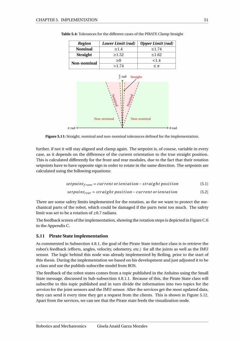
CHAPTER 5. IMPLEMENTATION 51
Table 5.4: Tolerances for the different cases of the PIRATE Clamp Straight
Region Lower Limit (rad) Upper Limit (rad)Nominal ≥1.4 ≤1.74Straight ≥1.52 ≤1.62
Non-nominal≥0 <1.4
>1.74 ≤π
0 radπ rad
π2 rad
Non-nominalNon-nominal
Nom
inal
Nom
inal
Straight
Figure 5.11: Straight, nominal and non-nominal tolerances defined for the implementation.
further, if not it will stay aligned and clamp again. The setpoint is, of course, variable in everycase, as it depends on the difference of the current orientation to the true straight position.This is calculated differently for the front and rear modules, due to the fact that their rotationsetpoints have to have opposite sign in order to rotate in the same direction. The setpoints arecalculated using the following equations:
set poi nt f r ont = cur r ent or i ent ati on − str ai g ht posi t i on (5.1)
set poi ntr ear = str ai g ht posi t i on − cur r ent or i ent ati on (5.2)
There are some safety limits implemented for the rotation, as the we want to protect the me-chanical parts of the robot, which could be damaged if the parts twist too much. The safetylimit was set to be a rotation of ±0.7 radians.
The feedback screen of the implementation, showing the rotation steps is depicted in Figure C.6in the Appendix C.
5.11 Pirate State implementation
As commented in Subsection 4.8.1, the goal of the Pirate State interface class is to retrieve therobot’s feedback (efforts, angles, velocity, odometry, etc.) for all the joints as well as the IMUsensor. The logic behind this node was already implemented by Reiling, prior to the start ofthis thesis. During the implementation we based on his development and just adjusted it to bea class and use the publish-subscribe model from ROS.
The feedback of the robot states comes from a topic published in the Arduino using the SmallState message, discussed in Sub-subsection 4.8.1.1. Because of this, the Pirate State class willsubscribe to this topic published and in turn divide the information into two topics for theservices for the joint sensors and the IMU sensor. After the services get the most updated data,they can send it every time they get a request from the clients. This is shown in Figure 5.12.Apart from the services, we can see that the Pirate state feeds the visualization node.
Robotics and Mechatronics Gisela Anaid Garza Morales

52 Increasing the Autonomy of the Pipe Inspection Robot PIRATE
ArduinoMega
PirateState
interfaceclass
Joint sen-sors service
IMU sen-sor service
Visualization nodepirate/smallState
/joint_states
/joint_states
/imu_rpy
Figure 5.12: Communication of the feedback from the Arduino Mega through the Pirate State and theservices.
5.12 Simple test mission implementation
As described in Section 1.4, part of the aims of the present thesis is to demonstrate the capabil-ities of the software framework by developing a simple example mission. The mission shouldshown how some of the possible partially autonomous tasks can be executed sequentially. Thisis done so that it is possible to see that a deliberative layer, where planning for such sequences,can be done in the future.
The mission was defined as the following steps:
1. Clamp Straight2. Drive forward3. Drive backward4. Home
Because of this, also a very simple verion of the Drive and Home classes was implemented.For the Home, inside the execute member function, a switch case structure was implemented,which follows the designed state machine showed in Figure 4.9. As mentioned previously,this implementation is not through an has the assumption that the robot starts clamped ina straight orientation. In the future, this should be complemented for unknown starting ori-entations. For the Drive, as it only has one state, the implementation of the execute memberfunction takes in a desired distance and velocity, and calculates the ideal time it should take forthe robot to achieve this distance at a certain velocity. This calculation is made according to:
x = (v0 + v f )t
2(5.3)
In equation 5.3, v0 represents the initial velocity which for the test mission will be 0rad/s. Thev f represents the desired (constant) velocity, t the required time and x the desired distance.This equation is then used to solve for the time and in this way achieve a desired distance. Thisdistances, in practice, were however not achieved, which might be due to friction between thewheels and the pipe (stiction) and some other non-idealities. This was then adjusted manuallyfor a chosen velocity of 150rad/s, and worked acceptably. However when really focusing on thisimplementation, it is perhaps a better option to use the odometry to measure the distance andnot the time. This, however, was not done because the idea was to test the drive functionality,without to much consideration for the actual distance accuracy. For the scope of this thesis, anin-depth implementation of the Drive function, is out of reach. Nonetheless, this proves thepotential of implementing the drive motion primitive for PAB-sequences.
With this, the implementation of the simple test mission designed for this thesis was com-pleted.
Gisela Anaid Garza Morales University of Twente

53
6 Results
This chapter will show the results obtained from the designed and implemented softwareframework. First the tests and their aim will be described. Then for each of them, the resultswill be presented and discussed.
6.1 Tests
In order to prove the effectiveness and the potential of the developed part of the softwareframework, various tests were designed. They will be comprehensive experiments and will becarried out to check the functionality at the PAB-level (which will prove also the effectivenessof the motion primitives because at some point they are all used inside the sequences).
The aim of this project focused heavily on the design and implementation of the Clamp Straightroutine. The tests for this sequence are given by:
• Simple clamp straight: The robot starts with an orientation within the tolerance range ofthe straight position. It is expected that the robot clamps and does not require to re-adjustthe orientation (no rotation).
• Nominal re-adjust clamp straight: The robot starts in an orientation within the toleranceof the nominal case, but outside of the straight range. It is expected that the robot clampsand re-adjusts slightly (small rotations) until it reaches the straight position.
• Non-Nominal clamp straight: The robot starts with an unknown orientation (either lyingon the right or left side normally) outside of the nominal case. It is expected that therobot clamps and re-adjusts (rotates) until it reaches the straight position, i.e. "gets up".
Because the 90mm pipe was the one that had all the implementations complete, the tests arecarried out in this pipe diameter. The tests were run 10 times for each of the scenarios. Foreach of the tests, a graphical assessment of the guards will be done, to observe and evaluatethe way the sequence works. A summary of the results for the guards evaluation is given inSection 6.6. Also some details on the torque measurements will be given, as proof of some ofthe inconsistencies found, reason for which they were not used as guards in the present work.The resolution of the angle measurement during the tests, is 0.01 radians for each of the bendand front angles and for the orientation angle it is around 1×10⁻⁹ radians.
As mentioned in Section 1.4, apart from evaluating the clamp straight behavior, a simple testmission forms part of the assessment. The mission consists on: clamping straight, driving for-ward, driving backward and homing the robot. The mission was run 10 times as well. The aimof this mission is to show the overall capacity of combining different PABs in sequences, whichwould be, in the future, generated by a supervisory layer.
To evaluate all routines, a log was obtained during the experiments which collects the mea-sured angles, efforts and orientation of the PIRATE robot.
6.2 Simple clamp straight in 90mm pipe
As mentioned previously, the simple clamp straight routine only consists of the steps: changingthe control modes to torque for the bend modules, move up the front one before clamp, andclamping both rear and front modules. As in this case the start-up orientation is within thestraight range, there will be no need to rotate to re-adjust.
The results of the experiment can be seen in Figure 6.1. It is worth noting that the logged in-formation has been obtained in a live test using the robot, however for better understanding,graphics of the 3D CAD PIRATE are shown along.
Robotics and Mechatronics Gisela Anaid Garza Morales

54 Increasing the Autonomy of the Pipe Inspection Robot PIRATE
Table 6.1 summarizes the milestones achieved at each instant of time by the robot along withthe control mode used. It is possible to see that the guards are reached as desired, and that theend result is a robot that has an straight orientation. This fact that the orientation is achievedcan bee seen as it is very close to the ideal straight position, marked with a pink dotted linein the graph of the rotation (angle 25) and orientation. From Figure 6.1 it is also possible toestimate the duration of this routine of around 10.77 seconds (average).
0 2 4 6 8 10 12 140
0.5
1
t1t2
An
gle
[rad
] Ang le 21
0 2 4 6 8 10 12 14
−1
0
1
t3
t4
An
gle
[rad
]
Ang le 22 Ang le 23
0 2 4 6 8 10 12 14−1
0123
An
gle
[rad
] Ang le 25 Or i ent ati on
0 2 4 6 8 10 12 14
−1
0
1
t2
t3
t i me [s]
An
gle
[rad
]
Ang le 26 Ang le 27
Figure 6.1: Results showing the achievement of the guards for the test Simple Clamp Straight in 90mmpipe
Table 6.1: Sequence of steps of motion primitives with respective control modes and guards for simpleclamp straight routine in 90mm pipe
StartTime
EndTime
MotionPrimitive
Controlmode
ModuleGuard(rad)
ModuleGuard(rad)
t1 t2 Move PWM Front 0.4 - -t2 t3 Clamp rear Torque Bend III 0.35 Bend IV -0.77t3 t4 Clamp front Torque Bend II 0.35 Bend I -0.77
Gisela Anaid Garza Morales University of Twente

CHAPTER 6. RESULTS 55
Figure 6.2 now shows the torque measurements during the operation, as it is possible to see,there are indeed peaks of torque when clamping, however as explained in both Chapters 4 and5, these were observed to be not very reliable as the magnitudes varied from a few mNm tomuch more considerable quantities. Here it is possible to see that the effort obtained from theslave 23 (Bend II) is considerably lower in magnitude as the other ones. This slave is expectedto behave like slave number 26 (Bend III) because of the mirrored design, however it is clearlydifferent. It is important to note that both slave 22 (Bend I) and 27 (Bend IV) present an increaseof torque during clamping, while 23 and 26 are supposed to have negative values. It will be seenin the other experiments that this is not always the case, and was therefore found unreliable asguard values.
0 2 4 6 8 10 12 14
−200
0
200
400
600
t1 t2 t3 t4
t i me [s]
Ef
for
t[m
Nm
]
E f f or t 22 E f f or t 23 E f f or t 26E f f or t 27
Figure 6.2: Effort measurements for bend modules for the simple clamp straight test in 90mm pipe.
6.3 Nominal re-adjust clamp straight in 90mm pipe
In this scenario, the PIRATE starts with an orientation within the defined nominal range, butoutside the straight tolerance range. According to the designed state machine, the sequence ofsteps to take are the following:
1. Move front module to be ready to clamp2. Clamp rear part3. Clamp front part4. Unclamp rear part5. Rotate the rear part according to the calculated difference with respect to the straight
position6. Clamp rear part7. Unclamp front part8. Rotate the front part according to the calculated difference with respect to the straight
position9. Clamp front part
This behavior can be observed in detail in the graphs of Figure 6.3. Again, the measurementshave been done with the robot, and the visual aids of each step are taken from the 3D CADPIRATE. Again in Figure 6.3 it is possible to see that the final position is very close to the valueindicated by the pink dotted line in the graph for rotational angle and orientation. This meansthat the sequence has finished within the straight position tolerance. A summary of each step’sguards and control modes is shown in Table 6.2.
This routine contains more steps than the previous one which is ready with one repetition andrequires no re-adjustments. Because of this, it is natural that the time this one takes (around 25
Robotics and Mechatronics Gisela Anaid Garza Morales
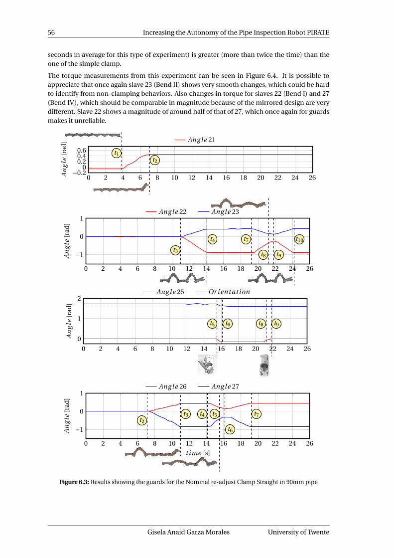
56 Increasing the Autonomy of the Pipe Inspection Robot PIRATE
seconds in average for this type of experiment) is greater (more than twice the time) than theone of the simple clamp.
The torque measurements from this experiment can be seen in Figure 6.4. It is possible toappreciate that once again slave 23 (Bend II) shows very smooth changes, which could be hardto identify from non-clamping behaviors. Also changes in torque for slaves 22 (Bend I) and 27(Bend IV), which should be comparable in magnitude because of the mirrored design are verydifferent. Slave 22 shows a magnitude of around half of that of 27, which once again for guardsmakes it unreliable.
0 2 4 6 8 10 12 14 16 18 20 22 24 26−0.2
00.20.40.6 t1
t2
An
gle
[rad
] Ang le 21
0 2 4 6 8 10 12 14 16 18 20 22 24 26
−1
0
1
t3
t4 t7
t8 t9
t10
An
gle
[rad
]
Ang le 22 Ang le 23
0 2 4 6 8 10 12 14 16 18 20 22 24 26
0
1
2
t5 t6 t8 t9
An
gle
[rad
]
Ang le 25 Or i ent ati on
0 2 4 6 8 10 12 14 16 18 20 22 24 26
−1
0
1
t2
t3 t4 t5
t6
t7
t i me [s]
An
gle
[rad
]
Ang le 26 Ang le 27
Figure 6.3: Results showing the guards for the Nominal re-adjust Clamp Straight in 90mm pipe
Gisela Anaid Garza Morales University of Twente
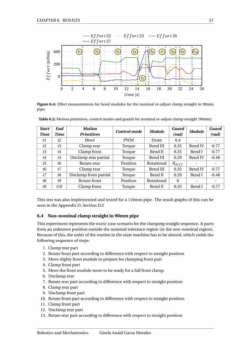
CHAPTER 6. RESULTS 57
0 2 4 6 8 10 12 14 16 18 20 22 24 26
0
200
400 t1 t2 t3 t4
t5
t6 t7 t8 t9 t10
t i me [s]
Ef
for
t[m
Nm
]
E f f or t 22 E f f or t 23 E f f or t 26E f f or t 27
Figure 6.4: Effort measurements for bend modules for the nominal re-adjust clamp straight in 90mmpipe.
Table 6.2: Motion primitives, control modes and guards for nominal re-adjust clamp straight (90mm)
StartTime
EndTime
MotionPrimitives
Control mode ModuleGuard(rad)
ModuleGuard(rad)
t1 t2 Move PWM Front 0.4 - -t2 t3 Clamp rear Torque Bend III 0.35 Bend IV -0.77t3 t4 Clamp front Torque Bend II 0.35 Bend I -0.77t4 t5 Unclamp rear partial Torque Bend III 0.29 Bend IV -0.48t5 t6 Rotate rear Position Rotational θdi f f - -t6 t7 Clamp rear Torque Bend III 0.35 Bend IV -0.77t7 t8 Unclamp front partial Torque Bend II 0.29 Bend I -0.48t8 t9 Rotate front Position Rotational 0 - -t9 t10 Clamp front Torque Bend II 0.35 Bend I -0.77
This test was also implemented and tested for a 110mm pipe. The result graphs of this can beseen in the Appendix D, Section D.2
6.4 Non-nominal clamp straight in 90mm pipe
This experiment represents the worst-case scenario for the clamping straight sequence. It partsfrom an unknown position outside the nominal tolerance region (in the non-nominal region).Because of this, the order of the routine in the state machine has to be altered, which yields thefollowing sequence of steps:
1. Clamp rear part2. Rotate front part according to difference with respect to straight position3. Move slighly front module to prepare for clamping front part4. Clamp front part5. Move the front module more to be ready for a full front clamp.6. Unclamp rear7. Rotate rear part according to difference with respect to straight position8. Clamp rear part9. Unclamp front part
10. Rotate front part according to difference with respect to straight position11. Clamp front part12. Unclamp rear part13. Rotate rear part according to difference with respect to straight position
Robotics and Mechatronics Gisela Anaid Garza Morales

58 Increasing the Autonomy of the Pipe Inspection Robot PIRATE
14. Clamp rear part15. Unclamp front part16. Rotate front part according to difference with respect to straight position17. Clamp front
0 5 10 15 20 25 30 35 400
0.5
1
t3 t4t5 t6
An
gle
[rad
] Ang le 21
0 5 10 15 20 25 30 35 40
−1
0
1
t4
t5 t9
t10
t11
t12 t15
t16
t17
t18
An
gle
[rad
]
Ang le 22 Ang le 23
0 5 10 15 20 25 30 35 40
−2
0
2 t2
t3 t7
t8 t10
t11 t13 t14 t16 t17An
gle
[rad
]
Ang le 25 Or i ent ati on
0 5 10 15 20 25 30 35 40
−1
0
1
t0 t1
t2 t6
t7 t8
t9 t12
t13 t14
t15
t i me [s]
An
gle
[rad
]
Ang le 26 Ang le 27
Figure 6.5: Results showing the achievement of the guards for the test Nominal re-adjust Clamp Straightin a 90mm pipe
Table 6.3 summarizes the steps of the sequence, together with the control modes and theguards that allow the transition between the states.
Gisela Anaid Garza Morales University of Twente
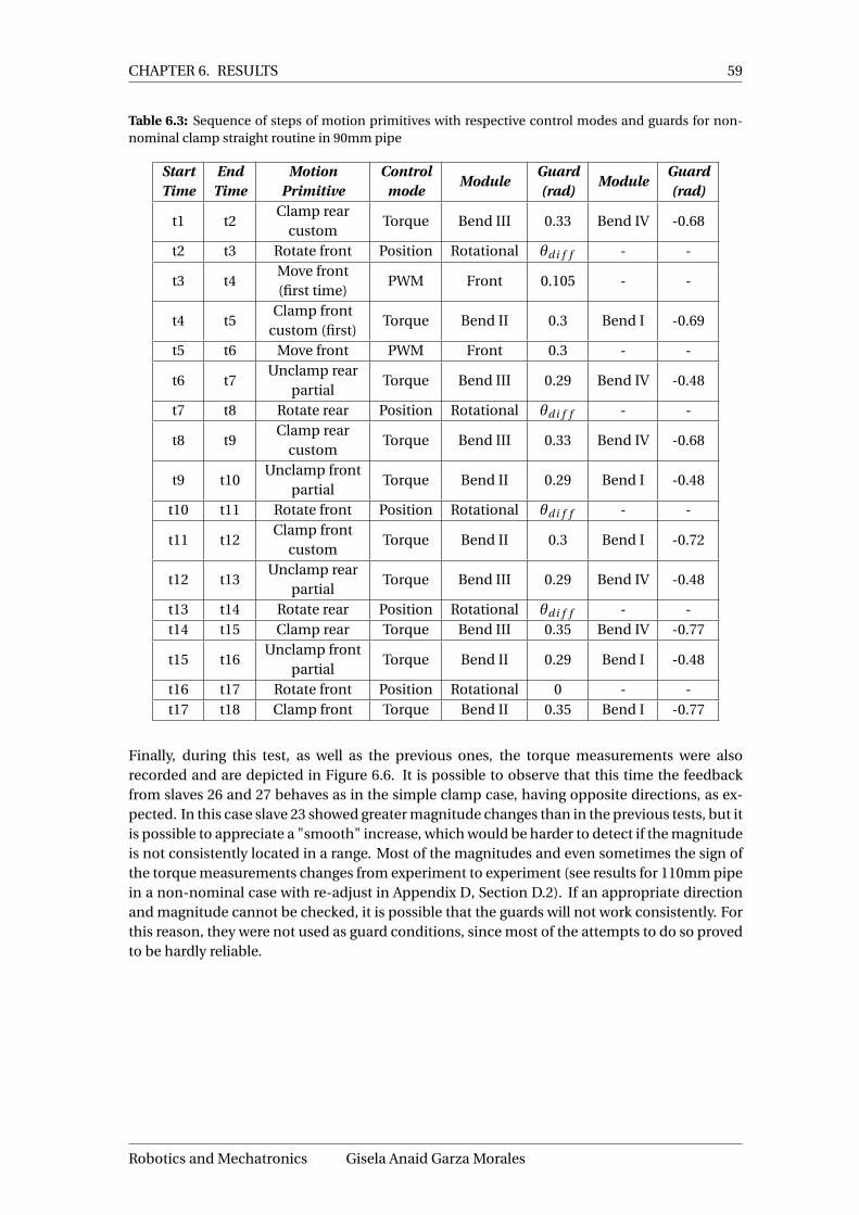
CHAPTER 6. RESULTS 59
Table 6.3: Sequence of steps of motion primitives with respective control modes and guards for non-nominal clamp straight routine in 90mm pipe
StartTime
EndTime
MotionPrimitive
Controlmode
ModuleGuard(rad)
ModuleGuard(rad)
t1 t2Clamp rear
customTorque Bend III 0.33 Bend IV -0.68
t2 t3 Rotate front Position Rotational θdi f f - -
t3 t4Move front(first time)
PWM Front 0.105 - -
t4 t5Clamp front
custom (first)Torque Bend II 0.3 Bend I -0.69
t5 t6 Move front PWM Front 0.3 - -
t6 t7Unclamp rear
partialTorque Bend III 0.29 Bend IV -0.48
t7 t8 Rotate rear Position Rotational θdi f f - -
t8 t9Clamp rear
customTorque Bend III 0.33 Bend IV -0.68
t9 t10Unclamp front
partialTorque Bend II 0.29 Bend I -0.48
t10 t11 Rotate front Position Rotational θdi f f - -
t11 t12Clamp front
customTorque Bend II 0.3 Bend I -0.72
t12 t13Unclamp rear
partialTorque Bend III 0.29 Bend IV -0.48
t13 t14 Rotate rear Position Rotational θdi f f - -t14 t15 Clamp rear Torque Bend III 0.35 Bend IV -0.77
t15 t16Unclamp front
partialTorque Bend II 0.29 Bend I -0.48
t16 t17 Rotate front Position Rotational 0 - -t17 t18 Clamp front Torque Bend II 0.35 Bend I -0.77
Finally, during this test, as well as the previous ones, the torque measurements were alsorecorded and are depicted in Figure 6.6. It is possible to observe that this time the feedbackfrom slaves 26 and 27 behaves as in the simple clamp case, having opposite directions, as ex-pected. In this case slave 23 showed greater magnitude changes than in the previous tests, but itis possible to appreciate a "smooth" increase, which would be harder to detect if the magnitudeis not consistently located in a range. Most of the magnitudes and even sometimes the sign ofthe torque measurements changes from experiment to experiment (see results for 110mm pipein a non-nominal case with re-adjust in Appendix D, Section D.2). If an appropriate directionand magnitude cannot be checked, it is possible that the guards will not work consistently. Forthis reason, they were not used as guard conditions, since most of the attempts to do so provedto be hardly reliable.
Robotics and Mechatronics Gisela Anaid Garza Morales

60 Increasing the Autonomy of the Pipe Inspection Robot PIRATE
0 5 10 15 20 25 30 35 40
−200
0
200
400t1
t2
t3 t4 t5
t6
t7
t8
t9
t10
t11
t12
t13
t14
t15 t16 t17 t18
t i me [s]
Ef
for
t[m
Nm
]E f f or t 22 E f f or t 23 E f f or t 26E f f or t 27
Figure 6.6: Efforts for bend modules for the non-nominal clamp straight in 90mm pipe
6.5 Simple test mission in 90mm pipe
Since the Chapter 1, it was mentioned that one of the aims of the present thesis is to demon-strate the capabilities of the software framework by integrating different PABs into a sequence(called mission). The scope of this thesis included the full design and implementation of onlyone PAB, the Clamp Straight. However, a simple implementation of the Home and Drive PABswas included with the intention of creating the test mission.
The test mission consists of the following sequence:
1. Move front to prepare for clamping front2. Clamp rear part3. Clamp front part4. Drive forward5. Drive backward6. Home
The intention is to see that it is possible to call different PABs execute functions sequentially.This provides a proof that the developed software framework for the Sequential control layer,can indeed be used when implementing a more abstract supervisory software layer.
The angle measurements and orientation, just like in the previous tests is shown in Figure 6.7.During the first four time events it is possible to see the same behavior and guards as the simpleclamp straight class presented in Section 6.2. Between the fourth and fifth time events, the driveoccurs. The time of the drive depends, of course, on the desired distance and velocity that issupplied to the functions. In this case the distances were forward 5cm and backward 3cm andthe velocity was set to 150mm/s. The final part of the graph corresponds to the execution of theHome PAB. There it is also possible to see the use of the unclamp front/rear motion primitivewhich hadn’t been used in the Clamp Straight routine (where the partial one was used).
Table 6.4 summarizes the steps of the sequence, together with the control modes and theguards that allow the transition between the states.
Gisela Anaid Garza Morales University of Twente

CHAPTER 6. RESULTS 61
Table 6.4: Sequence of steps of motion primitives with respective control modes and guards for simplemission routine in 90mm pipe
StartTime
EndTime
MotionPrimitive
Controlmode
ModuleGuard(rad)
ModuleGuard(rad)
t1 t2 Move PWM Front 0.4 - -t2 t3 Clamp rear Torque Bend III 0.35 Bend IV -0.77t3 t4 Clamp front Torque Bend II 0.35 Bend I -0.77
t4 t5Drive forward
andDrive backward
PWM(Velocity)
Bend I, II,III, IV,
Rotationaland Rear
Timeaccording
todistance
- -
t5 t6 Unclamping front Torque Bend II 0.03 Bend I -0.2t6 t7 Unclamping rear Torque Bend III 0.07 Bend IV -0.25t7 t8 Moving front PWM Front -60 - -
0 2 4 6 8 10 12 14 16 18 20 22 24 26 280
0.5
1
t1t2 t7
t8
An
gle
[rad
] Ang le 21
0 2 4 6 8 10 12 14 16 18 20 22 24 26 28
−1
0
1
t3
t4 t5
t6
An
gle
[rad
]
Ang le 22 Ang le 23
0 2 4 6 8 10 12 14 16 18 20 22 24 26 28
−2
0
2
An
gle
[rad
]
Ang le 25 Or i ent ati on
0 2 4 6 8 10 12 14 16 18 20 22 24 26 28
−1
0
1
t2
t3 t6
t7
t i me [s]
An
gle
[rad
]
Ang le 26 Ang le 27
Figure 6.7: Results showing the achievement of the guards for the simple test mission in a 90mm pipe
Robotics and Mechatronics Gisela Anaid Garza Morales

62 Increasing the Autonomy of the Pipe Inspection Robot PIRATE
6.6 General guards evaluation
Having carried out the necessary tests, Table 6.5 presents a summary of all the guards’ results.The table contains the worst case value seen during the testing, which refers to the closes valueto the guard. Also an approximate average of the value for each motion primitive over all thetests. With these results, it is possible to see that the guards chosen during the implementationhave been effective throughout the different tests and scenarios.
Table 6.5: Summary of the results of the guards throughout the experiments
Motion Primitive Module Angle Worst case (rad) Average (rad) Guard (rad)
Clamp FrontBend I α 0.4 0.42 0.35Bend II β -0.82 -0.85 -0.77
Clamp RearBend III β 0.42 0.44 0.35Bend IV α -0.79 -0.82 -0.77
Unclamp Frontpartial
Bend I α -0.37 -0.34 -0.48Bend II β 0.21 0.2 0.29
Unclamp Rearpartial
Bend III β 0.2 0.2 0.29Bend IV α -0.35 -0.33 -0.48
Unclamp RearBend III β -0.01 -0.09 0.07Bend IV α 0.02 0.06 -0.15
Unclamp FrontBend I α -0.09 0.00 -0.2Bend II β 0.01 0.00 0.03
Clamp rear customBend III β 0.42 0.43 0.3Bend IV α -0.78 -0.79 -0.68
Clamp front custom(first time)
Bend I α -0.75 -0.77 -0.69Bend II β 0.33 0.34 0.3
Clamp front custom(upcoming times)
Bend I α -0.77 -0.77 -0.72Bend II β 0.35 0.36 0.3
Move front (nominal) Front γ 0.43 0.445 0.4Move front (non-nom
first time)Front γ 0.25 0.265 0.105
Move front (non-nomupcoming times)
Front γ 0.37 0.38 0.3
Align Rotational θ 0.03 0.01 ±0.0425
Gisela Anaid Garza Morales University of Twente

63
7 Conclusions and Recommendations
7.1 Conclusions
The aim of this assignment was, in broad terms, to increase the level of autonomy of the PIRATErobot. The reasons for this are related to the fact that handling the robot manually makes theinspection labor-intensive and requires a specialized operator to control the robot.
The major issue relates to the robot’s autonomy, nonetheless, this is a complex task, and itnormally requires an elaborated system control architecture. By means of a layered controlapproach, several levels of autonomy for the PIRATE were defined, amongst which this project’sscope was delimited to constructing the Sequential layer. In this way, the project sought todevelop a software framework for this layer, which in general handles partially autonomousbehaviors and corresponding robot feedback.
The design and implementation of the software framework and corresponding elements arepresented in detail in Chapters 4 and 5, respectively. The development was subjected to testsin different scenarios (nominal and not-nominal) from which the results are discussed in Chap-ter 6. In synthesis, the most relevant findings were:
• Message size and frequency limitation: Because serial communication between the lap-top and the Arduino Mega was used, a limitation to the size and frequency of the sentmessages was necessary to avoid communication problems. Therefore the maximumarray size that is transmitted at a time contains 13 integers (16-bit) and the maximumfrequency for sending messages to the Arduino was set to a maximum of 10Hz (which issimilar to the setpoint update rate from the Arduino Mega to the local ATmega boards).This resulted in a relatively stable communication.
• Centralized system for message sharing: One of the key aspects for the design was basedon a centralized (composite) class. In this way coherency and consistency between thedifferent operation modes (handled in individual classes) was achieved.
• Client-server model: Another relevant aspect of the design is the use of a client servermodel to separate the request and handling of the partially autonomous behaviors. Inthis way, the program that listened to the user interface’s requests, could run in paral-lel with the server which executed the behavior. This allowed the desired non-blockingfunctionality, which meant that some requests of the user interface could be executed atthe same time as a partially autonomous behavior.
• Using the blackboard design pattern for sensor information: Like in any other con-trolled system, feedback played a major role for the development of the PABs. Becauseof this, it was important that sensor information was available upon request, to avoid theneed of constantly updating at moments when it is not required. To do this ROS providesa blackboard-like communication paradigm called services, where a server is constantlyupdating the variables, and can provide a client with the information upon request. Thisproved to be a very efficient method for distributing the sensors’ feedback among differ-ent classes.
• Motion primitives concept: This concept was first introduced by Dertien in 2014 [1] andwas observed to be a very good option for describing the steps to perform during a PAB.By thinking in motion primitives, the sequences were designed such that each state rep-resented a motion primitive. This proved to be quite intuitive which made simpler tobreak down complex routines.
• Using joint angles as feedback for the bend modules: Given the fact that the bend mod-ules are controlled in the sequences using torque, it made sense to use the torque mea-surements as feedback. This, however, proved to be hard to accomplish in practice. It was
Robotics and Mechatronics Gisela Anaid Garza Morales

64 Increasing the Autonomy of the Pipe Inspection Robot PIRATE
found that the torque magnitudes varied greatly, that the signs changed sometimes andin general that they were not very consistent during the tests. This could be due to thedeformation of the wheels, play in the mechanical parts, the lack of rigidity of the printedprototype, or overall lack of robustness of the torque controller, etc. Angle feedback waslater tested and yielded better results and more repeatability than the torque, thereforethis was chosen as a feedback for the bend modules.
• Handling of non-nominal situations: A robust partially autonomous behavior shouldbe able to handle at least the most significant situations in which the robot can be. Agood delimitation of the handled cases as well as the related assumptions, helped duringthe design and implementation process. In this way, during the design phase special at-tention was put to this situation, for which some additional states and new guards whereintegrated to the sequences.
• Possibility to carry out missions: In the same manner that the motion primitives weresupposed to encapsulate small functions of the PIRATE, the PAB concept sought to en-close more complex sequential functionality that can be called and reused when neededby a supervisory (planning) software layer. Based on this and as a proof of concept, asimple mission was designed and implemented. During the testing, the mission was suc-cessfully completed.
In this study it was possible to see the importance of the software control layers approach,which greatly facilitated the design process and accomplished modularity and re-usability.Once the layers were defined, it was easier to limit each class’ boundaries and functions. Be-cause of the time limitation, the scope of the study was limited to the design and implemen-tation of one PAB and just the basics of others (to be able to combine them into a mission).Nonetheless, the pattern followed to design the Clamp Straight PAB, can be reused and ad-justed for the future creation of other PABs. A relevant point to discuss is that the present studyencountered some limitations during implementation and testing. The limitations have to domainly with the robot, which was found to be sometimes unstable and mechanically too frag-ile. This reduces the reliability of the developed software because of unexpected failures due towiring problems, mechanical play, etc. In spite of this, the study was able to provide the firststeps towards autonomous architecture for the PIRATE. It presents a suitable software frame-work for further development of other PABs in the Sequential layer, as well as potential forcreating more complex missions by integrating them.
7.2 Recommendations
In general, the purpose of this study was to take the first steps towards more autonomous be-haviors for the PIRATE. In that sense, the software framework presented offers a good base forfuture development. The centralized structure works very well in keeping the information con-sistent through all the different programs, so it is recommended to keep this approach. Themodularity of each classes is also worth mentioning as it allows modifications to be very lo-cal, and to spread across the different levels. One example of this is that if the User interfaceis changed in the future, the parts like UI Input Driver and possibly the switch case inside theMapper won’t be applicable anymore. Nonetheless, all the logic starting from the Pirate Serverclass would be unaffected by the change, as long as the format for sending the goals is kept.
Even though the developed software works well as a first prototype of building more au-tonomous conditions there is still room for improvement. As the scope of this study aimedat the construction of only one PAB class, the design did not make use of the inheritance pos-sibility for classes. For future design and implementation of the other PAB classes, it is recom-mended to take advantage of the inheritance and create a PAB parent class (super-class), andmake specializations of for each of the PABs themselves. Another aspect that must be furtherevaluated is the necessary accuracy of the orientation guard (in straight position). The current
Gisela Anaid Garza Morales University of Twente

CHAPTER 7. CONCLUSIONS AND RECOMMENDATIONS 65
accuracy for this is around ±0.0425 radians. This sometimes showed to be a little too strict,which causes too many re-adjustments (longer sequence). This should be assessed, so thatperhaps the tolerances can be widened.
In general, the communication between ROS and Arduino Mega worked acceptably, howeverthere were times were the feedback would stop being sent from the Arduino Mega, and thus thesequences would fail. Another thing that happened less frequently was that when just startingthe robot, it would start moving unrequested and uncontrollably. Tests with the oscilloscopedid not show particularly obvious problems. Furthermore, the feedback from the Arduino, didnot present any setpoints being sent from ROS. This suggests that it might be due to connec-tor or wiring (hardware) problems. Such situation could bring problems in the future, so it isstrongly suggested that more attention is put into improving the robustness of the wiring andchecksums in the PICO boards. Due to the time limitation, thorough failure root cause analysisfell out of the scope of the present study.
In general the Arduino Mega microcontroller has some processing limitations that should beconsidered when having a wider scope for the autonomy of the PIRATE. When increasing thecomplexity on the system, there is a possibility that the communication through the Arduinomight not be sufficient or that more failures like this would keep happening. It is, therefore,suggested to look into other options to communicate the laptop with the local controllers, pos-sibly using a RTOS (Real-Time operating system).
During the design and implementation of the motion primitives, the torque measurements,which were the originally intended source of feedback for the bend modules, were found tobe considerably inconsistent and could not be used. Theoretically, since the clamping processis based on exerting a force on the pipe wall, the best option for feedback should be to usetorque measurements. For this reason, it is strongly suggested to pay attention to improvingthe reliability of the torque measurements and integrate these as guards along with the foundangle guards. Having a combination of position and torque feedback as conditions shouldprovide more repeatability and overall improve the logic’s robustness.
Also, with the experience from implementing a very basic Drive PAB, it was seen that perhapsfor exact measurements of distance and robot location, sensor fusion techniques should beimplemented. This because, only the odometry or the velocity might not be enough to takeinto account possible movements that result from clamping, unclamping, and other PABs, etc.
In general for the PIRATE, the current prototype of the robot, fabricated using 3D printing,has some evident limitations. Repairs had to be frequent and this reduced a lot of time forthe design and implementation, as well as decreasing the overall reliability of the developedsoftware, because of external unexpected failures. It is, therefore, strongly recommended tomove towards a more robust prototype, with less fragile and less deformable materials. Thiswould reduce the possibilities to break and also the mechanical play present in the robot, whichcan highly affect the sensor measurements.
Finally, improving the visualization was also out of scope for the present study. Since nominaland non-nominal cases depend heavily on the orientation of the robot, it would be desiredintegrate the IMU data so that the visualization provides an accurate image of the orientationof the robot.
Robotics and Mechatronics Gisela Anaid Garza Morales
66 Increasing the Autonomy of the Pipe Inspection Robot PIRATE
AcknowledgementsI would like to thank my amazing parents and brother for their wonderful support throughoutthis adventure. To my lovely grandfather and my aunt that witnessed this from heaven. Tomy wonderful family and friends, the new and the old, I am forever in your debt for all yourincredible support. To Armando, who has been my rock for the last 8 years, thank you darling.
To all the wonderful people from RAM from which I learned much more than science.
Last but not least, this thesis wouldn’t have been possible without the full support of the schol-arship granted by the Instituto de Innovacion y Transferencia de Tecnologia de Nuevo Leon(http://i2t2.org.mx) together with the scholarship of Consejo Nacional de Ciencia y Tecnologia(http://www.conacyt.gob.mx)
Gisela A. Garza MoralesEnschede, August 2016
Gisela Anaid Garza Morales University of Twente

67
A Appendix: Designed classes
Setpoint
- nh_ : ros::Node- setpoint_msg : PirateSetpoint_Array- pub_setpoint : ros::Publisher
+ setElement(uint8 PICOboardID, uint8 Motor, int16 setpoint) : void+ setArray(int16 setpoint_array[13]) : void+ getElement(uint8 PICOboardID, uint8 Motor) : void+ publish() : bool
Figure A.1: Setpoint class
Control
- nh_ : ros::Node- control_msg : PirateControl_Array- pub_control : ros::Publisher
+ setElement(uint8 PICOboardID, uint8 Motor, int16 controlMode) : void+ setArray(int16 control_array[12]) : void+ getElement(uint8 PICOboardID, uint8 Motor) : void+ publish() : bool
Figure A.2: Control class
Limit
- nh_ : ros::Node- limit_msg : PirateLimit_Array- pub_limit : ros::Publisher
+ setElement(uint8 PICOboardID, uint8 Motor, int16 limit) : void+ setArray(int16 control_array[4]) : void+ getElement(uint8 PICOboardID, uint8 Motor) : void+ publish() : bool
Figure A.3: Class diagram for Limit class
Pirate Manager
- nh : ros::Node- setpoint_ : Setpoint&- limit_ : Limit&- control_ : Control&- mapper : Mapper*- server : Pirate_Server*
+ periodic_manual_publish() : void
Figure A.4: Pirate Manager class
Robotics and Mechatronics Gisela Anaid Garza Morales
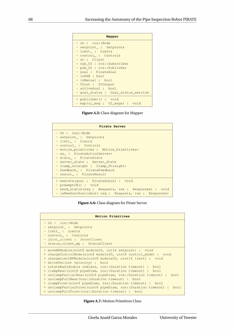
68 Increasing the Autonomy of the Pipe Inspection Robot PIRATE
Mapper
- nh : ros::Node- setpoint_ : Setpoint&- limit_ : Limit&- control_ : Control&- ac : Client- sub_UI : ros::Subscriber- pub_UI : ros::Publisher- goal : PirateGoal- inPAB : bool- inManual : bool- UIout : UIOutput- activeGoal : bool- goal_status : Goal_status_service
+ publisher() : void- map(ui_msg : UI_msg&) : void
Figure A.5: Class diagram for Mapper
Pirate Server
- nh : ros::Node- setpoint_ : Setpoint&- limit_ : Limit&- control_ : Control&- motion_primitives : Motion_Primitives*- as_ : PirateActionServer*- state_ : PirateState- server_state : Server_State- clamp_straight : Clamp_Straight*- feedback_ : PirateFeedback- result_ : PirateResult
+ execute(goal : PirateGoal&) : void- preemptCB() : void- send_status(req : Request&, res : Response&) : void- isNewGoalAvailable( req : Request&, res : Response&)
Figure A.6: Class diagram for Pirate Server
Motion Primitives
- nh : ros::Node- setpoint_ : Setpoint&- limit_ : Limit&- control_ : Control&- joint_client : JointClient- status_client_mp : StatusClient
+ moveBFModule(uint8 moduleID, int16 setpoint) : void+ changeControlMode(uint8 moduleID, uint8 control_mode) : void+ changeLimitBFModule(uint8 moduleID, uint16 limit) : void+ driveVel(int velocity) : bool+ rotateRad(double radians, ros::Duration timeout) : bool+ clampRear(uint8 pipeDiam, ros::Duration timeout) : bool+ unclampPartialRear(uint8 pipeDiam, ros::Duration timeout) : bool+ unclampFullRear(ros::Duration timeout) : bool+ clampFront(uint8 pipeDiam, ros::Duration timeout) : bool+ unclampPartialFront(uint8 pipeDiam, ros::Duration timeout) : bool+ unclampFullFront(ros::Duration timeout) : bool
Figure A.7: Motion Primitives Class
Gisela Anaid Garza Morales University of Twente

APPENDIX A. APPENDIX: DESIGNED CLASSES 69
Clamp Straight
- nh_ : ros::Node- setpoint_ : Setpoint&- control_: Control&- limit_ : Limit&- motion_primitives_ : Motion_Primitives&- joint_client : JointClient- status_client : StatusClient- imu_client : IMUClient+ state_ : ClampStraightState
+ execute(uint8_t pipe_diameter) : bool - checkCase(void) : int- checkOrientation(void) : double- isAligned(void) : bool- isStraight(void) : bool- isNominal(void) : bool- getJointPosition(int8 jointElement) : double
Figure A.8: Clamp Straight class
Home
- nh_ : ros::Node- setpoint_ : Setpoint&- control_: Control&- limit_ : Limit&- motion_primitives_ : Motion_Primitives&- joint_client : JointClient- status_client : StatusClient- imu_client : IMUClient+ state_ : HomeState
+ execute() : bool- getJointPosition(int8 jointElement) : double
Figure A.9: Home class
Drive
- nh_ : ros::Node- setpoint_ : Setpoint&- control_: Control&- limit_ : Limit&- motion_primitives_ : Motion_Primitives&+ state_ : DriveState
+ execute(int16 distance) : bool
Figure A.10: Drive class
Robotics and Mechatronics Gisela Anaid Garza Morales

70 Increasing the Autonomy of the Pipe Inspection Robot PIRATE
B Appendix: Additional mapping information
B.1 Pirate State array mapping per PICO Board
Table B.1: Pirate state sent from the Arduino Mega per PICO Board
PICOBoard ID
Element number1 2 3 4 5 6 7 8 9
20 Odometry VelocityDriveLoad
Angle(Bend)
BendLoad
Torque - - -
21 Odometry VelocityDriveLoad
Angle(Bend)
BendLoad
Torque - - -
22 Odometry VelocityDriveLoad
Angle(Bend)
BendLoad
Torque - - -
23 Odometry VelocityDriveLoad
Angle(Bend)
BendLoad
Torque - - -
24 Odometry VelocityDriveLoad
Angle(Bend)
BendLoad
Torque - - -
25 Odometry VelocityDriveLoad
X(IMU)
Y(IMU)
Z(IMU)
U(IMU)
V(IMU)
W(IMU)
26 Odometry VelocityDriveLoad
Angle(Bend)
BendLoad
Torque - - -
27 Odometry VelocityDriveLoad
Angle(Bend)
BendLoad
Torque - - -
28 Odometry VelocityDriveLoad
Angle(Bend)
BendLoad
Torque - - -
Gisela Anaid Garza Morales University of Twente

71
C Appendix: Feedback screen
C.1 Mapper class implementation
Figure C.1: Feedback screen when changing operation mode
C.2 Pirate Server class implementation
Figure C.2: Feedback screen at start-up, showing the construction of the classes
Figure C.3: Feedback screen when cancelling a PAB operation.
Robotics and Mechatronics Gisela Anaid Garza Morales

72 Increasing the Autonomy of the Pipe Inspection Robot PIRATE
C.3 Motion Primitives class implementation
Figure C.4: Timeout during clamp routine
C.4 Clamp straight class implementation
Figure C.5: Feedback screen of the implementation showing a successfully completed clamp routine
Gisela Anaid Garza Morales University of Twente

APPENDIX C. APPENDIX: FEEDBACK SCREEN 73
Figure C.6: Feedback screen’s messages during rotations
Robotics and Mechatronics Gisela Anaid Garza Morales

74 Increasing the Autonomy of the Pipe Inspection Robot PIRATE
D Appendix: Transition conditions and Results
D.1 Transition conditions for Clamp Straight state machine
Table D.1: Transition guards for the Clamp Straight state machine
State Transition Transition conditions (guards)
Change control modesMoving front Nominal case
Clamp rear partial Non- nominal case
Moving FrontClamping rear full Nominal case
Clamping front Partial Non- nominal case
Clamping Rear Full
Clamping front full Front not clamped AND nominal caseUnclamping front Front clamped AND Rear part not Straight
Rotating front Front not clamped AND non-nominal case
ENDFront clamped AND Rear part Straight AND
Robot Aligned
Clamping Front Full
Unclamping Rear Rear clamped AND Rear part not StraightClamping Rear Full Rear part not clamped AND Nominal case
Unclamping FrontRear clamped AND Rear part Straight AND
Robot not AlignedClamping Rear Partial Rear part not clamped AND Non-nominal case
ENDRear clamped AND Rear part Straight AND
Robot AlignedUnclamping Rear Rotating rear N/A
Rotating RearClamping rear full
Scenario 1:Front clamped AND Rear notclamped AND Rear part Straight
Scenario 2: Front clamped AND Rear notclamped AND Robot is Aligned AND Nominal case
Clamping rear PartialFront clamped AND Rear not clamped AND
Robot is Aligned AND Non-nominal caseUnclamping Front Rotating Front N/A
Rotating FrontClamping Front Full
Scenario 1: Rear clamped AND Front notclamped AND Rear part Straight
Scenario 2: Rear clamped AND Front notclamped AND Robot is Aligned AND Nominal case
Clamping Front PartialRear clamped AND Front not clamped AND
Robot is Aligned AND Non-nominal caseAND Front module lifted
Moving FrontRear clamped AND Front not clamped AND
Robot is Aligned AND Non-nominal caseAND Front module not lifted
Clamping Front PartialUnclamping Rear Rear clamped
Rotating Rear Rear not clampedMoving Front First time clamping front
Clamping Rear PartialUnclamping Front Front clamped
Rotating Front Front not clamped
Gisela Anaid Garza Morales University of Twente
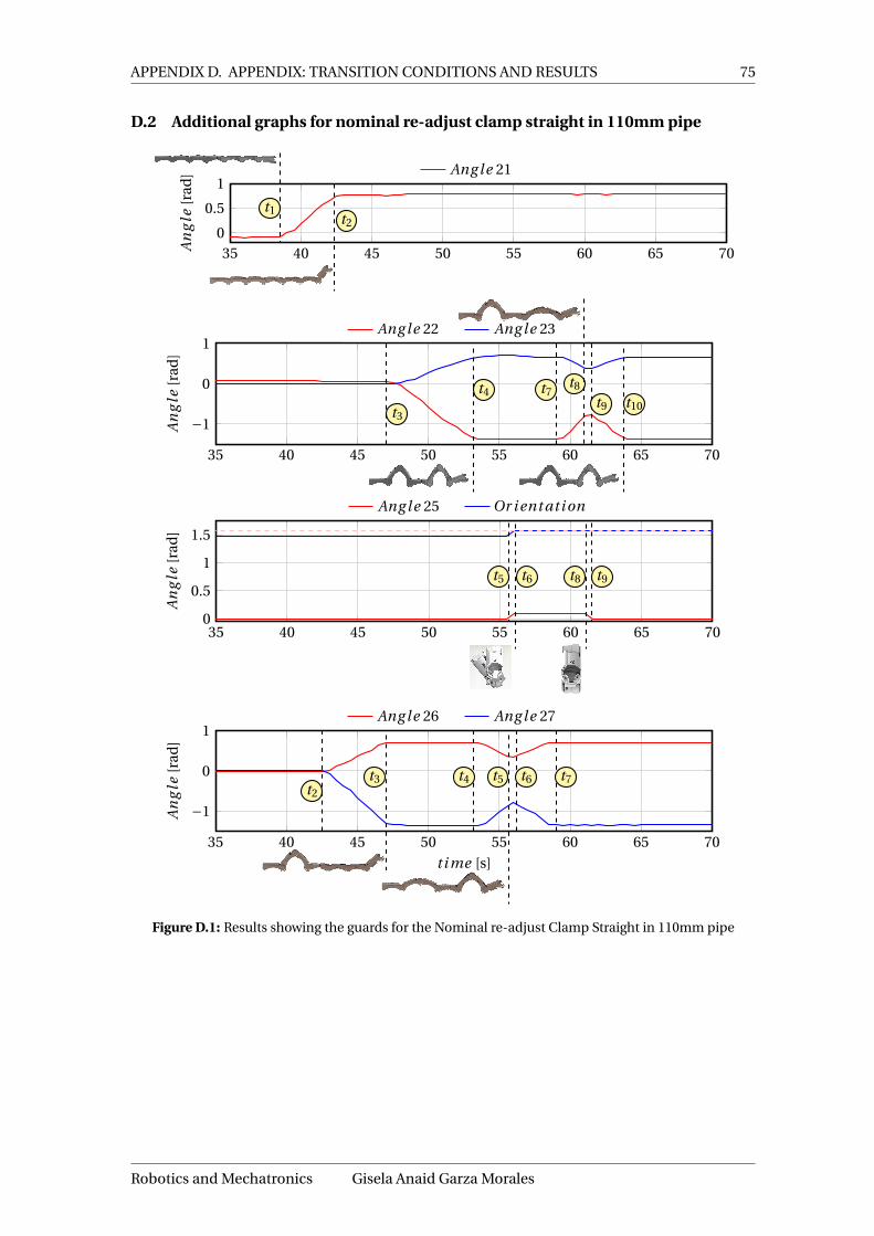
APPENDIX D. APPENDIX: TRANSITION CONDITIONS AND RESULTS 75
D.2 Additional graphs for nominal re-adjust clamp straight in 110mm pipe
35 40 45 50 55 60 65 700
0.5
1
t1t2
An
gle
[rad
] Ang le 21
35 40 45 50 55 60 65 70
−1
0
1
t3
t4 t7t8
t9 t10
An
gle
[rad
]
Ang le 22 Ang le 23
35 40 45 50 55 60 65 700
0.5
1
1.5
t5 t6 t8 t9
An
gle
[rad
]
Ang le 25 Or i ent ati on
35 40 45 50 55 60 65 70
−1
0
1
t2
t3 t4 t5 t6 t7
t i me [s]
An
gle
[rad
]
Ang le 26 Ang le 27
Figure D.1: Results showing the guards for the Nominal re-adjust Clamp Straight in 110mm pipe
Robotics and Mechatronics Gisela Anaid Garza Morales
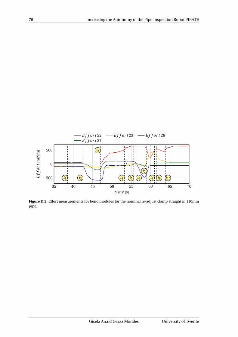
76 Increasing the Autonomy of the Pipe Inspection Robot PIRATE
35 40 45 50 55 60 65 70
−500
0
500
t1 t2
t3
t4 t5 t6
t7
t8 t9 t10
t i me [s]
Ef
for
t[m
Nm
]
E f f or t 22 E f f or t 23 E f f or t 26E f f or t 27
Figure D.2: Effort measurements for bend modules for the nominal re-adjust clamp straight in 110mmpipe.
Gisela Anaid Garza Morales University of Twente

APPENDIX D. APPENDIX: TRANSITION CONDITIONS AND RESULTS 77
D.3 Graphic sequence of non-nominal clamp straight
Lying on one side non-nominal case
Clamp Rear Partial Rotating Front
t0 t1 t2
Moving Front Clamp Front Partial Unclamping Reart3 t5 t4 t11 t6
Rotating Rear Clamp Rear Partial Unclamping Frontt7 t8 t9 t15
Rotating Front Unclamping Rear Rotating Reart10 t16 t12 t13
Clamp Rear Full Clamp Front Full Succeededt14 t17 t18
Table D.2: Non-nominal case graphical sequence for a 90mm pipe
Robotics and Mechatronics Gisela Anaid Garza Morales

78 Increasing the Autonomy of the Pipe Inspection Robot PIRATE
E Appendix: Mapping of the user interface
Figure E.1: Mapping of the user interface
Table E.1: Mapping per channel in MIDI panel
Channel Description Works in Operation Mode0 Slider Rear Module Not controlled1 Slider Bend IV Manual2 Slider Bend III Manual3 Slider Bend II Manual4 Slider Bend I Manual5 Slider Front Module Manual6 Slider Tilt Front Camera Manual / PAB7 Slider Drive (wheels) Manual
16 Rear LEDs Manual / PAB17 Knob Limits Bend IV Manual18 Knob Limits Bend III Manual19 Knob Limits Bend II Manual20 Knob Limits Bend I Manual21 Knob Pan Front Camera Manual / PAB22 Front LEDs Manual / PAB23 Knob Rotational Module Manual
32Not used (Control mode
Rear module)Manual
33Control modes Bend IV
(PWM - off / Torque - on)Manual
34Control modes Bend III
(PWM - off / Torque - on)Manual
35Control modes Bend II
(PWM - off / Torque - on)Manual
36Control modes Bend I
(PWM - off / Torque - on)Manual
37Control modes Front M.
(PWM - off / Position - on)Manual
38Control modes Tilt F. Camera
(PWM - off / Position - on)Manual / PAB
39Control modes Drive
(PWM )Manual
Gisela Anaid Garza Morales University of Twente

APPENDIX E. APPENDIX: MAPPING OF THE USER INTERFACE 79
Table E.2: Mapping per channel in MIDI panel - Cont.
Channel Description Works in Operation Mode41 Start (Play) Manual / PAB42 Stop Manual / PAB
43Change Mode of Operation
(Manual - off / PAB - on)Manual / PAB
44 Not used -45 Used for calibration Manual46 Not used -48 Not used -49 Immediate Stop Bend IV Manual50 Immediate Stop Bend III Manual51 Immediate Stop Bend II Manual52 Immediate Stop Bend I Manual53 Immediate Stop Front M. Manual54 Immediate Stop Tilt Camera Manual55 Immediate Stop Drive Manual
58Not used (can be used for
other PABs)PAB
59 PAB Clamp Straight in 90mm PAB60 For calibration Manual61 Not used -62 Not used -64 Not used -65 Calibrate Bend IV Manual66 Calibrate Bend III Manual67 Calibrate Bend II Manual68 Calibrate Bend I Manual69 Calibrate Front Module Manual70 Calibrate Tilt Front Camera Manual71 Not used -
Robotics and Mechatronics Gisela Anaid Garza Morales
80 Increasing the Autonomy of the Pipe Inspection Robot PIRATE
F Appendix: Running instructions and Tips and tricks
F.1 Instructions to start the software
1. Run the Manager.Launch file, that starts the rosserial node, the UI input and outputnodes. To run input the following to the terminal (within the catkin workspace):
roslaunch pirate_viz Manager.launch
2. Run the pirate_manager_node, by inputting the following to the terminal (within thecatkin workspace):
rosrun pirate pirate_manager_node
3. Run the pirate state node and the visualization contained in the pirate_manager_node byinputting the following to the terminal (within the catkin workspace):
roslaunch pirate_viz pirate_gui.launch
In this software, the feedback screen is observed at the pirate manager node.
F.2 Sending Manual Commands
1. Once the system is running, press the Start (Play) button until the LED lights on. Bydefault the system starts in Manual mode.
2. If the system is previously in PAB mode, first press the Stop button and then the REWINDbutton and toggle it until the LEDs are off. This means the system is in Manual mode (alsocheck the feedback screen which will indicate the current mode of operation). Once it iscorrectly set, press again the Start button to be able to send commands again.
3. Once in manual mode, all the buttons, sliders and knobs mentioned in Table E.1 fromAppendix E.
4. To stop at any time press the Stop button, or to individually stop each of the joints, pressthe corresponding M-button.
5. To change the control mode for each joint, press the S-button for the corresponding one.Normally PWM is when the LED is off, and the other mode when it is on.
6. To change the limits of the bending modules, move the corresponding knobs.7. To turn on the LEDs also move the corresponding knobs.8. To calibrate press the Set button and hold it while pressing the corresponding R-button
of the desired joint to calibrate.9. There is a special mode called No Limits All which overrides the current bending limits.
This is called when pressing the Set button and holding it while pressing the Rec button.
F.3 Sending PAB commands
1. Press Start (Play), to start the system.2. Since the system is by default in Manual, first press the Stop button. Next press the
Rewind button and toggle it until the LED turns on. This means that the system is inPAB mode. Once it has been successfully changed, press Start again to be able to sendPAB commands (or the allowed manual commands in PAB mode).
3. The only PAB command developed in this thesis is mapped to the Track Left button. Thisone calls the Clamp Straight 90mm.
4. To cancel the PAB execution at any time, press the Stop button.
Gisela Anaid Garza Morales University of Twente
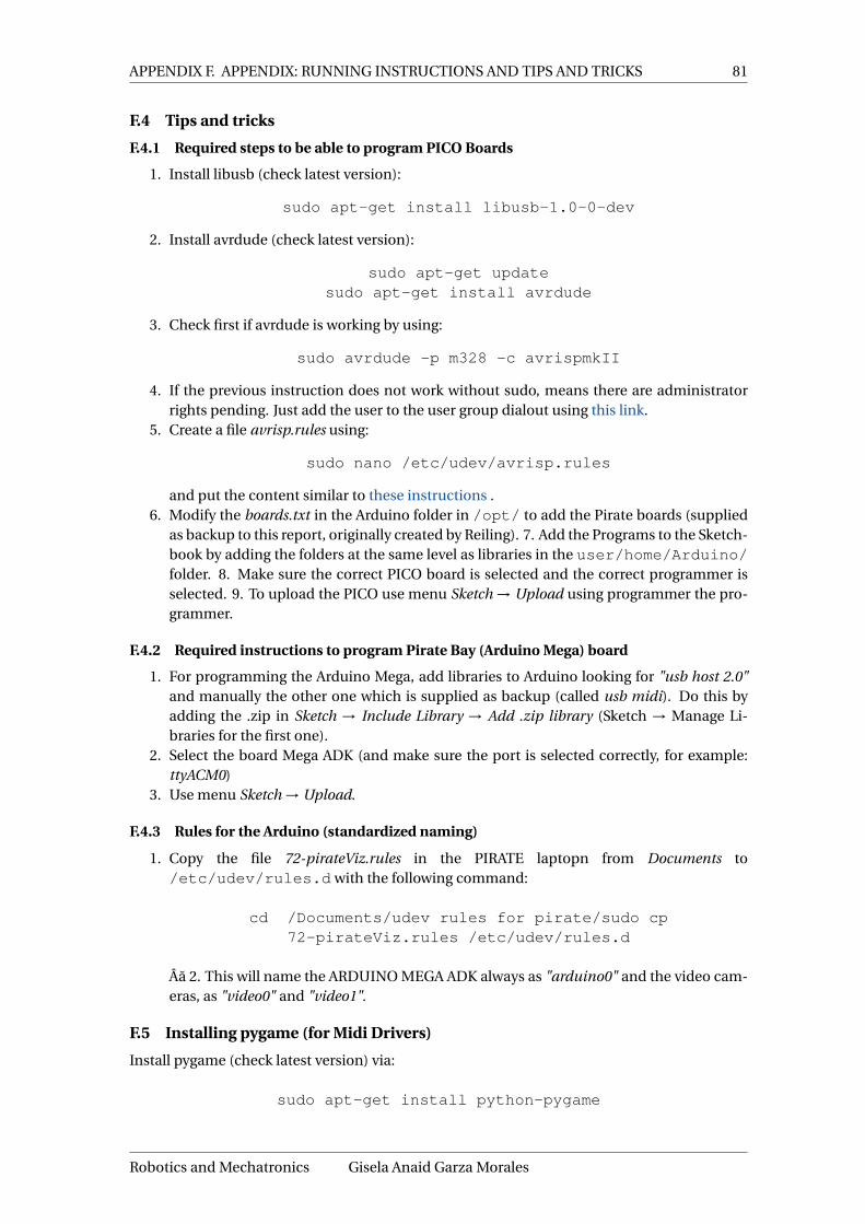
APPENDIX F. APPENDIX: RUNNING INSTRUCTIONS AND TIPS AND TRICKS 81
F.4 Tips and tricks
F.4.1 Required steps to be able to program PICO Boards
1. Install libusb (check latest version):
sudo apt-get install libusb-1.0-0-dev
2. Install avrdude (check latest version):
sudo apt-get updatesudo apt-get install avrdude
3. Check first if avrdude is working by using:
sudo avrdude -p m328 -c avrispmkII
4. If the previous instruction does not work without sudo, means there are administratorrights pending. Just add the user to the user group dialout using this link.
5. Create a file avrisp.rules using:
sudo nano /etc/udev/avrisp.rules
and put the content similar to these instructions .6. Modify the boards.txt in the Arduino folder in /opt/ to add the Pirate boards (supplied
as backup to this report, originally created by Reiling). 7. Add the Programs to the Sketch-book by adding the folders at the same level as libraries in the user/home/Arduino/folder. 8. Make sure the correct PICO board is selected and the correct programmer isselected. 9. To upload the PICO use menu Sketch → Upload using programmer the pro-grammer.
F.4.2 Required instructions to program Pirate Bay (Arduino Mega) board
1. For programming the Arduino Mega, add libraries to Arduino looking for "usb host 2.0"and manually the other one which is supplied as backup (called usb midi). Do this byadding the .zip in Sketch → Include Library → Add .zip library (Sketch → Manage Li-braries for the first one).
2. Select the board Mega ADK (and make sure the port is selected correctly, for example:ttyACM0)
3. Use menu Sketch → Upload.
F.4.3 Rules for the Arduino (standardized naming)
1. Copy the file 72-pirateViz.rules in the PIRATE laptopn from Documents to/etc/udev/rules.d with the following command:
cd /Documents/udev rules for pirate/sudo cp72-pirateViz.rules /etc/udev/rules.d
Âa 2. This will name the ARDUINO MEGA ADK always as "arduino0" and the video cam-eras, as "video0" and "video1".
F.5 Installing pygame (for Midi Drivers)
Install pygame (check latest version) via:
sudo apt-get install python-pygame
Robotics and Mechatronics Gisela Anaid Garza Morales
82 Increasing the Autonomy of the Pipe Inspection Robot PIRATE
F.5.1 General tips and tricks
1. If when running the first time the Manager.launch file, there is an error, run it again. Thishappens sometimes when starting up.
2. If there is a communication error, either that the Arduino Mega is not sending the feed-back, restart the system.
3. If one of the sensors/efforts is not responding (zero-valued or any value that doesn’tchange), restart the system.
Gisela Anaid Garza Morales University of Twente

83
Bibliography[1] E. Dertien, “Design of an inspection robot for small diameter distri-
bution mains. phd thesis,” University of Twente, 2014. [Online]. Avail-able: http://eprints.eemcs.utwente.nl/25317/01/Design_of_an_inspection_robot_for_small_diameter_gas_distribution_mains.pdf
[2] P. van Vollenhoven, “Gasexplosie na breuk van gasdistributieleiding. technical report,”Raad voor de transportveiligheid, Tech. Rep., 2002.
[3] E. Dertien, “System specifications for pirate,” University of Twente, Enschede, Tech. Rep.,2006.
[4] J. V. op Nijhuis, “Development of a pipe inspection robot. master thesis,” University ofTwente, 2007.
[5] S. Spijksma, “Redesign of the pirate bending module. internship report,” University ofTwente-DEMCON, Enschede, Tech. Rep., 2009.
[6] B. Burkink, “Pirate propulsion unit. bachelor thesis,” University of Twente, 2009.
[7] D. Borgerink, “Development of the second pirate prototype using rapid prototyping. mas-ter thesis,” University of Twente, 2012.
[8] E. Dertien, “Design of pirate mainboard,” University of Twente, Enschede, Tech. Rep.,2007.
[9] J. Ansink, “Electronic design for a gas pipe inspection robot. internship report,” Demcon,Enschede, Tech. Rep., 2007.
[10] H. Reemeijer, “Control of a pipe inspection robot. master thesis,” University of Twente,2010. [Online]. Available: https://www.ram.ewi.utwente.nl/aigaion/attachments/single/1129
[11] E. Drost, “Measurement system for pipe profiling. master thesis,” University of Twente,2009. [Online]. Available: https://www.ram.ewi.utwente.nl/aigaion/attachments/single/1018
[12] M. Brilman, “Embedded vision system for pirate. bachelor thesis,” Saxion - University ofTwente, 2011.
[13] M. Reiling, “Implementation of a monocular structured light vision system for pipe in-spection robot pirate. master thesis,” University of Twente, 2014.
[14] T. Mennink, “Self localization of pirate inside a partially structured environment. masterthesis,” University of Twente, 2010. [Online]. Available: https://www.ram.ewi.utwente.nl/aigaion/attachments/single/1140
[15] C. Doggen, “Wireless state feedback and control of a pipe inspection robot. master thesis,”University of Twente, 2010.
[16] J. M. O’Kane, A Gentle Introduction to ROS. University of South Carolina, 2016.
[17] L. Joseph, Mastering ROS for Robotics Programming. Packt Publishing Ltd., 2015.
[18] B. P. Douglass, Doing Hard Time: Developing Real-Time systems with UML, objects, frame-works, and patterns. Addison Wesley Longman, Inc., 1999.
[19] D. Bell. The class diagram. [Online]. Available: https://www.ibm.com/developerworks/rational/library/content/RationalEdge/sep04/bell/
[20] R. Hartanto, A Hybrid Deliberative Layer for Robotic Agents. Springer-Verlag Berlin Hei-delberg, 2011.
[21] J. K. et al., “Intelligent robot software architecture,” Recent Progress in Robotics, 2008.
[22] E. Gat, “On three-layer architectures,” California Institute of Technology, 1998.
Robotics and Mechatronics Gisela Anaid Garza Morales

84 Increasing the Autonomy of the Pipe Inspection Robot PIRATE
[23] R. A. Brooks, “A robust layered control system for a mobile robot,” IEEE Journal of Roboticsand Automation, 1986.
[24] J. F. Broenink, M. A. Groothuis, P. M. Visser, and B. Orlic, “A model-driven approach toembedded control system implementation,” in Proceedings of the 2007 Western Multicon-ference on Computer Simulation WMC 2007, San Diego, J. Anderson and R. Huntsinger,Eds. San Diego: SCS, San Diego, January 2007, pp. 137–144.
[25] S. Bennet, Real-Time Computer Control: An Introduction. Prentice-Hall, 1988.
[26] J. F. Broenink and Y. Ni, “Model-driven robot-software design using integrated models andco-simulation,” in Proceedings of SAMOS XII, J. McAllister and S. Bhattacharyya, Eds., Jul.2012, pp. 339 – 344.
[27] M. M. Bezemer, “Cyber-physical systems software development - way of working and toolsuite,” Ph.D. dissertation, University of Twente, Nov. 2013.
[28] K. P. Edwin Dertien, Mohammad Mozzafari Foumashi and S. Stramigioli, “Developmentof an inspection robot for small diameter gas distribution mains,” International Gasunion Research Conference, IGRC 2014, 2014. [Online]. Available: https://www.ram.ewi.utwente.nl/e13/files/pirate/articles/WP3-4_Dertien-1.pdf
[29] G. A. Pratt and M. M. Williamson, “Series elastic actuators,” MIT Artificial Intelligent Lab-oratory, 1995.
[30] M. Lootsma, “Design of the global software structure and controller framework forthe 3tu soccer robot. master thesis,” University of Twente, 2008. [Online]. Available:http://essay.utwente.nl/58246/1/scriptie_M_Lootsma%5B1%5D.pdf
Gisela Anaid Garza Morales University of Twente