030 - - inl research library digital repository · 030 vol. i gend general public ... it has...
TRANSCRIPT


, -: ... ~'l (
GEND: 030
Vol. I
GEND General Public Utilities • Electric Power Research Institute • U.S. Nuclear Regulatory Commission • U.S. Department of Energy
Quick Look Inspection: Report on the Insertion of a Camera into the TMI-2 Reactor Vessel through a Leadscrew Opening Volume I
Bechtel Northern Corporation
March 1983
Prepared for the U.S. Department of Energy Three Mile Island Operations Office Under Contract No. DE-AC07-76ID01570 MASTER DB{fflOn OF THIS OQcU!1lE!n IS U~UM\Tf.D

•
-.,".:~ .. , .
Printed in the United States of America
Available from
National Technical Information Service
U.S. Department of Commerce
5285 Port Royal Road
Springfield, VA 22161
NTIS Price Codes: Printed Copy A07
Microfiche A01
DISCLAIMER
This book was prepared as an account of work sponsored by an agency of the United
States Government. Neither the United States Government nor any agency thereof,
nor any of their employees, makes any warranty, express or implied, or assumes any
legal liability or responsibility for the accuracy, completeness, or usefulness of any
information, apparatus, product or process disclosed, or represents that its use would
not infringe privately owned rights. References herein to any specific commercial
product, process, or service by trade name, trademark, manufacturer, or otherwise,
does not necessarily constitute or imply its endorsement, recommendation, or favoring
by the Untied States Government or any agency thereof. The views and opinions of authors expressed herein do not necessarily state or reflect those of the United States Government or any agency thereof.
. :" - .... . . \ . .. ~.
i

DISCLAIMER GEND---030-Vol.l
DEB3 009354 GErm 030
Vol. I This report was prepared as an account of work sponsored by an agency of the United States Government. Neither the United States Government nor any agency thereof, nor any of their employees, makes any warranty, express or implied, or assumes !lny legal liability or responsibility for the accuracy, completeness, or usefulness of any information, apparatus, product, or process disclosed", or represents that its use wO'Ald not infringe privately owned rights. Reference herein to any specific commercial product, process, or service by trade name, trademark, manufacturer, or otherwise does not necessarily constitute or imply its endorsement, recommendation, or favoring by the United States Government or any agency ther~f. The views and opinions of authors expressed herein do not necessarily state or reflect those of the United States Government or any agency thereof.
Distribution Category: UC-78 TMI Supplement
QUICK LOOK INSPECTION: REPORT ON THE INSERTION OF A CAMERA
INTO THE TMI-2 REACTOR VESSEL THROUGH A LEADSCREW OPENING.
VOLUME I
Published March 1983
Bechtel Northern Corporation Gaithersburg, Maryland 208n
NOTICE PORTIONS Of THIS .REPORT An£ IllEGIBLE.'
It has !re-oil reprOd'lGed frDf~ the best available cU~!l to permit the broadest possible availability I •
Prepared for EG&G Idaho, Inc. Under Subcontract No. K-9067
and the U.S. Department of Energy Three Mile Island Operations Office
Under Contract No. DE-AC07·76ID01570

ABSTRACT
The purpose of the insertion of a camera into the reactor vessel through a
leadscrew opening, known as the Quick Look, was to visuallY inspect a portion
of the plenum and fuel inside the TMI-2 reactor vessel in order to make an
assessment of the;r condition. This was accomplished by uncoupling the center
control rod drive mechanism (CROM) leadscrew from the control rod assembly and
removing the leadscrew from the CROM, resulting in an access path to a plenum
guide tube and to the core region. This report d~scribes the preparations and
plant modifications required to accomplish this Quick Look. Additionally, the
report summarizes the containment entries, data collected, and the observations
from the camera inspections. As a result of the Quick Look, two general con
clusions can be made: (a) although u significant amount of debris was observed,
plenum distortion was not apparent, and (b) the top center of the core was ob
served in the form of a loose rubble bed approximately 5 feet below the design location.
i i
- -- - .---:-~-- - 1-----:--- ,--- ,- -- ~
j-/ ,.t· 11-' ,- :. il'~- 'i ,-¥ ~ - ... .J! • W . . . . - ;:: -" : "'" .

1.
2.
3.
CONTENTS
I NTRODUCTI ON
1.1 Objective of the Quick Look Inspection
1.2 Established Schedule
1.3 Sequence of Quick Look Camera Inspections
1. 3. 1 1. 3. 2 1. 3. 3
Quick Look I - July 21, 1982 Quick Look II - August 6, 1982 Quick Look III - August 12, 1982
METHODS AND APPROACH
2.1 Supporting Studies and Licensing Documents
2.1.1 2.1.2 2.1.3 2.1.4
Criticality Analysis Decay Heat Removal Analysis Gaseous Release Analysis Safety Evaluation
2.2 Leadscrew Uncoupling Plan and Tool Development
2.2.1 2.2.2
Leadscrew Uncoupling and Removal Plan Tool Development
2.3 Plant Modification and Additions
2.3.1 2.3.2 2.3.3 2.3.4
Venting and Draining Water Level Monitoring Leadscrew Rigging and Handling Communications Systems
2.4 Operator Training
2.5 Procedure Preparation
2.6 Radiological Considerations
2.6.1 2.6.2 2.6.3
EXECUTION
Radiological Predictions ALARA Provisions Operational Radiological Controls
3.1 Containment Entries
iii
----------------------~-------~--------------------------
1-1
1-1
1-2
1-3
1-3 1-4 1-5
2-1
2-1
2-1 2-2 2-4 2-5
2-6
2-6 2-6
2-10
2-10 2-13 2-14 2-15
2-17
2-18
2-21
2-2l 2-23 2-27
3-1
3-1

4.
5.
CONTENTS (Continued)
3.2 Preliminary Data Collected
3.2.1 3.2.2 3.2.3
Gas and Liquid Samples Leadscrew Information Leadscrew Uncoupling Descriptions for Drive Locations 8H and 7K
3.3 Observations from the Camera Inspections
3.3.1 3.3.2 3.3.3
Observed Condition of the Plenum Distribution of Core Debris Extent of Core Damage
3.4 Core Probe
3.5 Leadscrew Uncoupling Activities
3.5.1 3.5.2 3.5.3 3.5.4
Description Data Explanation Results of Leadscrew Uncoupling Activities Explanation of Each Uncoupling
3.6 Descriptions of Photographs
SUMMARY
4.1 Quick Look Objectives and Schedule
4.2 Methods and Approach
4.2.1 4.2.2 4.2.3 4.2.4 4.2.5
Supporting Studies and Licensing Documents Leadscrew Uncoupling Plan and Tool Development Plant Modifications anJ Additions Operator Training and Procedure Preparation Radiological Predictions and ALARA Considerations
4.3 Execution
4.3.1 4.3.2
4.3.3 4.3.4 4.3.5
REFERENCES
Containment Entries and Data Collection Leadscrew Uncoupling Descriptions for Drive Locations 7K and 8H Observations from the Camera Inspections Core Probe Experiment Leadscrew Uncoupling Activities
APPENDIX A DESIGN FuNCTIONAL CRITERIA AND DRAWINGS FOR NEW AND MODIFIED TOOLS
iv
3-7
3-7 3-13
3-14
3-17
3-19 3-20 3-21
3-22
3-22
3-22 3-25 3-27 3-32
3-46
4-1
4-1
4-1
4-2 4-3 4-3 4-4 4-4
4-5
4-5 4-6
4-7 4-7 4-7
5-1

2-1
3-1
3-2
3-3
3-4
3-5
3-6
3-7
1-1
1-2
1-3
1-4
1-5
1-6
1-7
1-8
2-1
2-2
2-3
3-1
3-2
3-3
3-4
CONTENTS (Continued)
TABLES
Procedure Work Supporting Quick Look
Quick Look Containment Entries
CROM Purge Sample from 10H CROM Vent
CROM Gas Sample from 10H CROM Vent
CROM Liquid Sample from 10H CROM Vent
ReS Liquid Sample Analysis from Reactor Vessel
CRDM 8H Gas Sample Analyses
Radioactivity Analyses of Leadscrew Samples
FIGURES
Cutaway view of the reactor vessel
Control rod drive mechanism
Plenum assembly
Control rod guide assembly
Fuel assembly
Control rod assembly
Leadscrew Quick Look
Locations of core control elements
CROM leadscrew uncoupling and parking plan
RCS level indication vs. system elevations
Quick Look communications systems
CROM venting tool
CROM top closure parts
Leadscrew 8H dose rates
Leadscrew 9E dose rates
v
2-19
3-1
3-7
3-8
3-9
3-11
3-12
3-15
3-5
3-6
3-7
3-8
3-9
3-10
3-11
3-12
3-13
3-14
3-15
3-16
3-17
3-18
3-19
3-20
3-2l
CONTENTS (Continued)
FIGURES (Cont.)
Leadscrew 88 dose rates
Alternate uncoupling tool
CROM torque tube assembly
Torque taker installation on leadscrew
Leadscrew nut assembly
Locations where the control rod spiders never moved up or down.
Locations where the spiders moved down less than 2 i I,ches after uncoup 1 i ng
Locations where the spiders moved up when lifted, but did not move down after uncoupling
Locations where the spiders dropped greater than 2 inches after uncoupling
Locations where the leadscrews have been uncoupled, but parking the leadscrews may be difficult
Locations where the leadscrews and torque takers are not bottomed on the torque belleville springs
Locations where parking problems car not be identified due to lack of data
Cutting of the leadscrew by the band saw
Removing the wrapped leadscrew from the service structure to a storage tube at the side of the service structure
Insertion of the camera into a CROM motor housing
Spring of undetermined length lying on the debris bed near the 8H position; depending on length, this is a control rod or fuel rod spring
Portion of a control assembly spider which was resting on the debris bed near the 8H position
vi

3-22
3-23
3-24
3-25
3-26
3-27
3-28
3-29
CONTENTS (Continued)
FIGURES (cont.)
The debris bed as observed during Quick Look I near the 8H position
Debris on top of a guide tube support plate in the 9E position (lower left is up)
Fuel rods at location 80 as viewed from below from location 9E
Burnable poison rod pellet on the debris bed near the 8H position
Debris lodged in upper end fitting ln the 9E position (left is up)
Loo~ing up at the upper gr"d with camera at the 9E position (Note eroded grillage at upper ri~ht)
Looking up at a split tube of a control rod guide assembly in the 9E position
Spring retainer plug (approximately 1 inch in diameter) in the 9E upper end fitting (left is up)
vii

3-22
3-23
3-24
3-25
3-26
3-27
3-28
3-29
CONTENTS (Continued)
FIGURES (cont.)
The debris bed as observed during Quick Look I near the 8H position
Debris on top of a guide tube support plate in the 9E position (lower left is up)
Fuel rods at location 80 as viewed from below from location 9E
Burnable poison rod pellet on the debris bed near the 8H position
Debris lodged in upper end fitting 1n the 9E position (left is up)
Loo!.ing up at the upper gr'd with camera at the 9E position (Note eroded grillage at upper riyht)
Looking up at a split tube of a control rod guide assembly in the 9E position
Spring retainer plug (approximately 1 inch in diameter) in the 9E upper end fitting (left is up)
vii

l. INTRODUCTION
1.1 Objective of the Quick Look Inspection
The objective of the Quick Look Inspection was to inspect control rod
guide tubes. a portion of the upper grid, the tops of fuel assemblies, and, if
upper end fittings were missing, the reactor core. This inspection provided
the first visual information on the condition of the core and upper internals
and was of significant interest to both researchers and recovery planners. A
significant benchmark was established from which the projected range of core
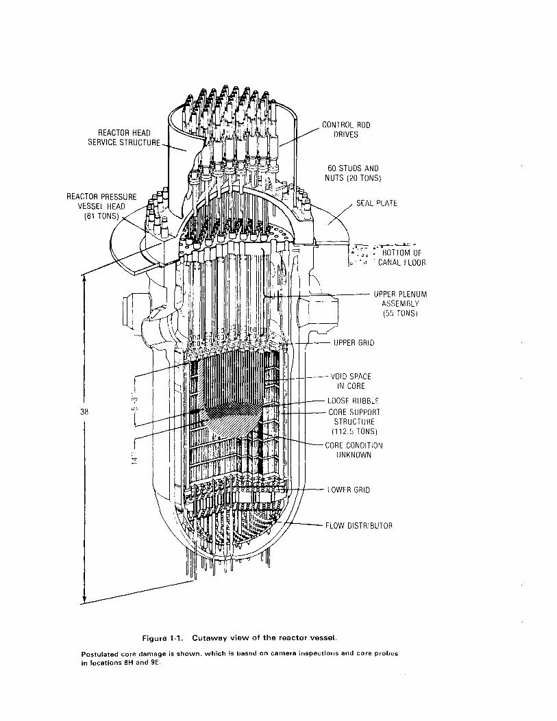
condition and accident sequence estimates can be narrowed (see Figure 1-1).
The method for obtaining this information was to insert a radiation
tolerant, underwater closed-ciruit television (CCTV) camera through an opening
created by the removal of a leadscrew from a control rod drive mechanism (CROM)
(see Figure 1-2). T~e camera was manipulated using the camera power cable and
a separate articlilating cable La ~btain access to the desired inspection areas
The ba~ic approac~ was to lower the TV camera from the top of a control
rod dri.e mechanism, dovln tilrollgh the 1eadscrew hole to the reglon of the tenth
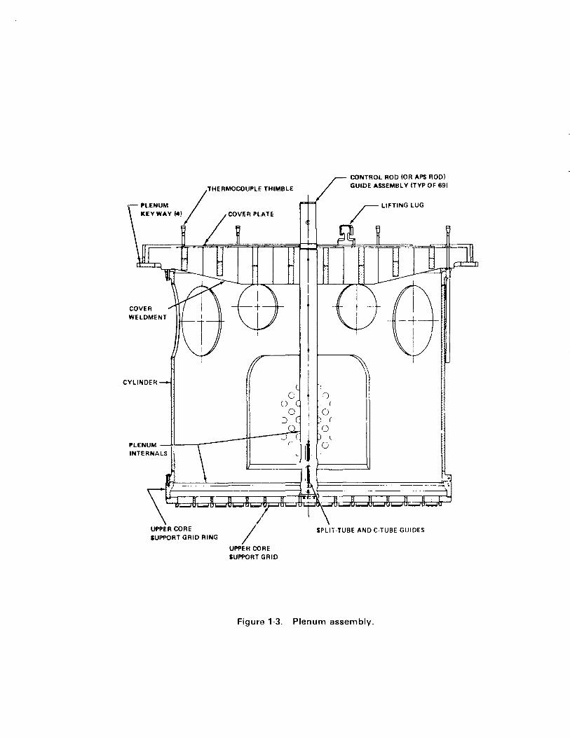
spacer plate of a guide tuDe in t~e upper plenum assembly (see Figure 1-3).
The main inspection was to start ln the general region of the tenth spacer
plate (~ee Figure ]-4) and then, depending on the conditions found, attempt the
1. General area ;nspect:on of the tenth spacer plate and upper end
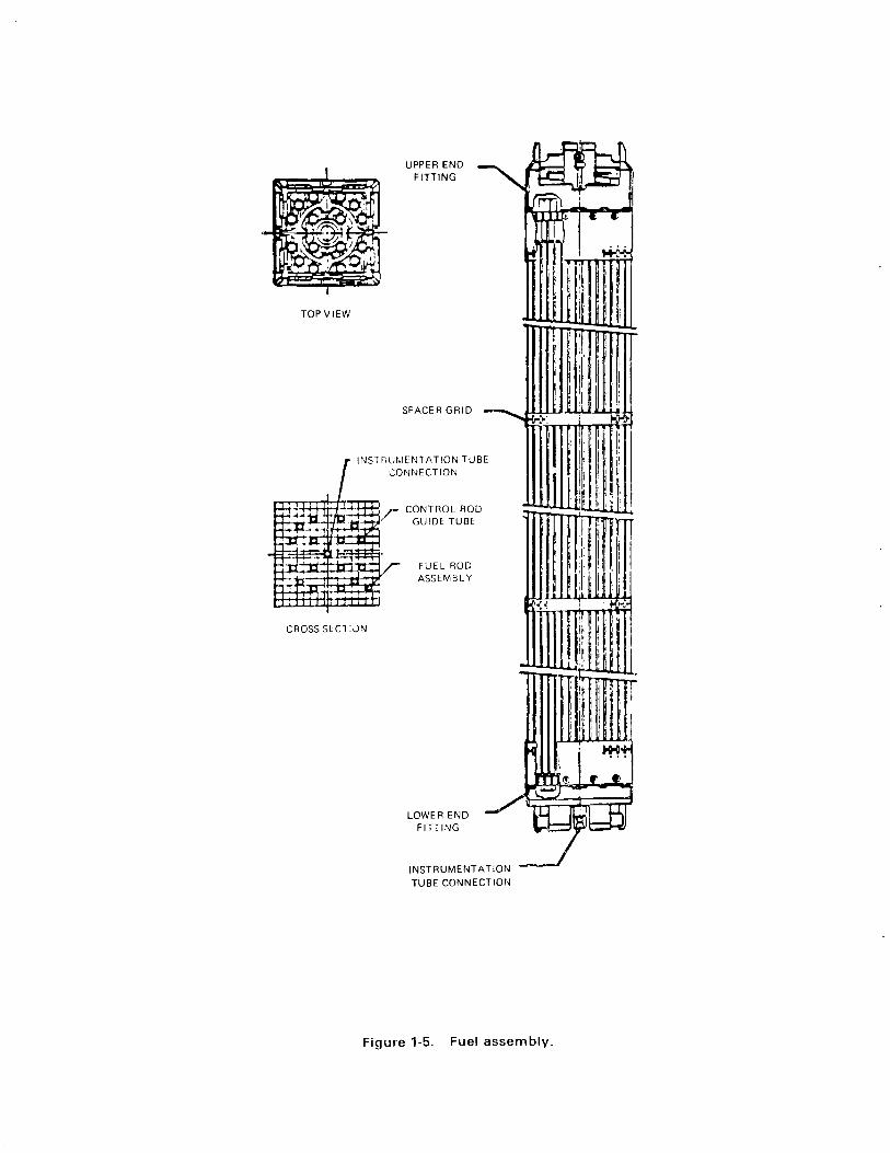
fitting of the fuel ~ss~mblj (see Figure 1-5) directly below
',he opened leadsc'ew hole.
2. Inspection nf the uppe" E'IlCJ fittings of the four adjacent fllel
assemblies by manip~,latiflCJ the 1') camera out the flo'N holes in
the sid e 0 f t. Ii e g u ide t 1I t, e .
1-1

I 3. Following the inspection of each ~djacent fuel assembly end
fitting, inspect the next outer fuel assembly which has a
control rod assembly (see Figure 1-6), in an attempt to determine
the status of its end fittings.
4. A detailed inspection of the end fitting directly below the
opened leadscrew hole, followed by a detailed inspection of the
tenth spacer plate and its guide tubes. If the inspection of
this region indicated that it has seen higher temperatures, the
eighth and ninth spacer castings were also to be inspected.
If, during the above examination, end fittings were found to be missing.
the general intent was to continue the inspection along the pattern described
above without lowering the camera into the fuel region. If an end fitting was
found to be missing from its normal position and the above illspections had been
basically completed, the lV camera was to be lowered through the opening to
determine where the top of the core was generally located, and a general
inspection made to determine conditions in that region.
As a follow-up to the core inspections, leadscrew uncoupling was attempted
on all the leadscrews not uncoupled tor the camera inspections. Information
gained from this activity will be used to determine what cuntingency tooling
will be required to support reactor vessel head removal.
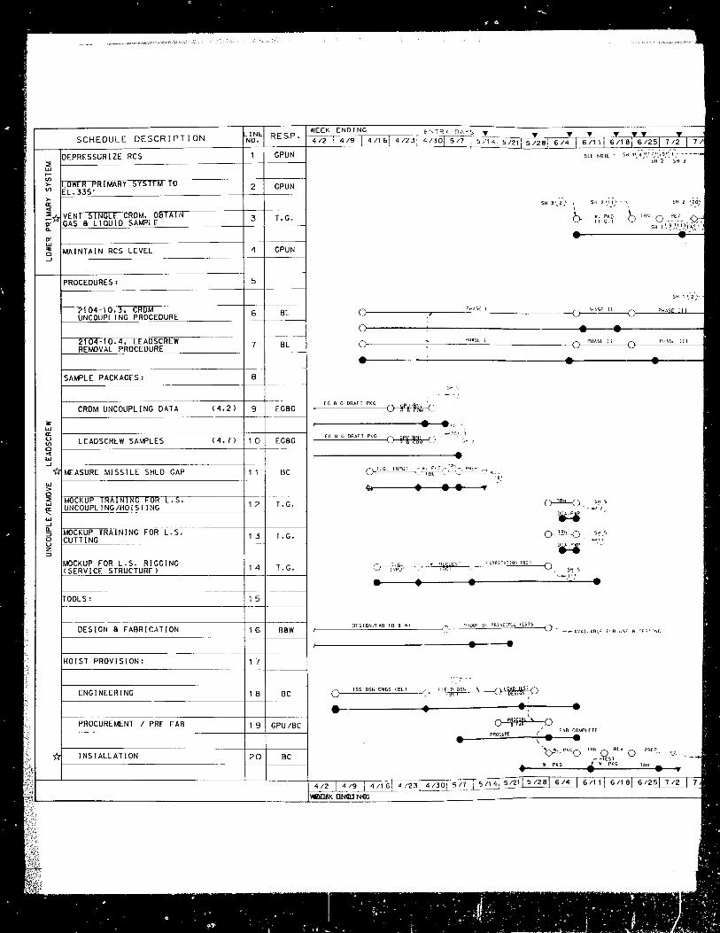
1.2 Establishea Schedule
The Leadscrew Quick Look Schedule No. S-l, Figure 1-7, reflects the
originally scheduled activities with a second line showing actual or forecast
dates for progress and performance rletermination. Key milestones for the task
included:
1. Safety evaluation approval
2. Lowering of the primary system water level
1-2

3. Removal and cutting of the leadscrew
4. Video inspection
The Quick Look I camera inspection was originally scheduled for the week
ending July 23. 1982, and was ir fact performed on July 21, 1982. After the
Quick Look I camera in~pection. Quick Look II, Quick Look III, and leadscrew
uncoupling activities were scheduled as follows:
o Quic~ ~ook II - August 5, 1932
o Q~ick Loo~ III - August 12, 1982
o LeaCsCl'ew Uncoup 1 i'1CJ - Au,~us t 23 and 15, 1982
1 ') ,J Sequence of QJick Look Camera Inspections
Tile Cafl121 Vias lowel'e.: ,;:tu 1,"Ie CROH quide t.lJ!JE' at p()'~jtioll SH (see Figure
1 - ~ \ '-' , 1. ::> i the ,n s 1; L' ~,., tie y u ide t u t) e ,'/ a ~ e " ami ned tot he 1 e .' e 1 0 I til e t; p
,'e fe,' en c e p) i n t s. t iJ e nel'l
lrl U,is position, a~ ir' [1osition 8H,
::w camel'a wClS the:" 'f:'U'lcted intG t:H" 211 QUlde tube and lowered into the
,~c)re "eqlon, Nothing wa~ ob:oe'''lied ,Hltii the camerCl encountered a rubble bed,
a P fJ I ~~ x i If' at", S fee t bel 0 v. t Ii e top 0 f the COl' ere 9 ion, Aft e r s c a II II i 11 g the
debri=, tne CClmerCl wac rotated upward into a vertical positioll alld raised to a
!' ;:1t f"om I'ihich the LJnder5~(je of U,e upper plenum assembly vias viewed,
t :, '~ ;J 0 ; i t i CJ f1, t. he cam era 1'1 a s rot ate d t h r 0 ugh
?SL' cJegr'ees at a point 1[: "L'>:'5 ;JIJove ti,e :'ubb1e bed vJithrJut obstr'uction. The
swee~, of the camel'a was 21 ;'~I't::S i'l diameteT', which indicated that thl;' void at
1- 3

the center of the core encompassed at least the nine fuel elements surrounding
position BH.
1.3.2 Quick Look II - August 6, 19B2
The leadscrews at the BB and 9E positions were removed in preparation for
this camera inspection. An auxiliary light was lowered into the void through
the BH guide tube. The first insertion of the camera took place on the core
periphery through BB. Ouring the inspection of the control spider, which was
in its normal position, the light on the camera failed. When the camera was
replaced, the ~nspection of the spider continued.
The camera was raised and maneuvered into an adjacent location where a
burnable pOlson rod assembly (BPRA) was located. From this position, the BPRA
retainer with the spider hub inside was visible. Since this spider and the one
at 8B were still in their normal locations, the camera could not be lowered
further.
After the camera was withdrawn from 8B, it was lowered into the core
region through the 9E guide tube. Nothing was encountered until the camera
reached the rubble bed, approximately 5 feet below the top of the core region.
The examination of the debris in the rubble bed was extensive, since much of
the debris was identifiable.
Attempts were made to rotate the camera around a vertical axis, as was
done in the first Quick Look; however, the camera and cable were repeatedly
obstructed. The camera was then pointed upward and raised until it came into
contact with the underside of the plenum. The junction of four upper end
fittings without fuel bundles attached, but still suspended from the underside
of the plenum, was observed.
1-4

1.3.3 Quick Look III - August 12, 1982
in this final camera inspection, the camera was inserted through the 9E
guide tube with the auxiliary light ir.serted through 8H. The inside of the
guide tube was reexamined, as were the underside of the plenum and the rubble.
A stainless steel rod was used to probe the rubble at positions 8H and 9E. In
both places, the rod appeared to penetrate 14 inches into the rubble bed (see
Section 3.4).
The first camera was removed and a second camera, fitted with a right
angle viewing lens, was inserted at 9E to perform a detailed examination of the
CROM guide tube. When the examination had been performed, a panoramic scan
was made 2 feet 6 inches below the top of the core region.
1-5
REACTOR HEAD SERVICE STRUCTURE
REACTOR PRESSURE VESSEL HEAD
(81 TONS)
38
CONTROL ROD DRIVES
60 STUDS AND NUTS (20 TONS)
SEAL PLATE
:- BOTTOM OF .• oJ' CANAL FLOOR
~~+t-J~=="",,<::~-- UPPER PLENUM
.... =~<~"'.<Cl>'oC~.~+-+--+--- UPPER GRID
ASSEMBLY (55 TONS)
.J:.U-I-j--- VO IDS PAC E IN CORE
~~-Hr-H~- LOOSE RUBBLE -lI-I+--+-+--- CO RES U PPO RT
STRUCTURE (1125TONS)
CORE CONDITION UNKNOWN
iR!~~I~m[fj~~I--- LOWER GRID
FLOW DISTRIBUTOR
Figure 1-1, Cutaway view of the reactor vessel.
Postulated core damage is shown, which is basod on camera inspections and core probes
in locations 8H and 9E.

P. L CONNECTO"
",ESSURE HOUSING
'NATER JACKET----"
SEGMENT ARM
Figure 1-2. Control rod drive mechanism.
CONTROL ROD COUPUNG
/
THERMOCOUPLE THIMBLE
- 1'1.ENUM
.EVWAV M' /"'V''''AH
COVER
CYLINDER
PLENUM __ lL ____ ~--------+~r----~J:c~ l INTERNALS (- '-J II
UPPER CORE SUPPORT GRID RING
/1 UPPEH CORE
SUPPORT GRID
.j (
o
CONTROL ROO (OR APS ROO) GUIDE ASSEMBL Y (TYP OF 69)
11
I
SPLIT -TUBE AND C-TUBE GUIDES
Figun~ 1-3. Plenum assembly.

I
I , , ,
-o
•
-'I
<{
t-<t
00 0:_ <to:
.. S t? "{ 0.. 0:
o ... .... c: o U
TOPVIEW
UPPER END FiniNG
SPACER GRID
INSTF;U~'ENTATION TUBE 'CONNECTION
CONTROL ROD GUIDE TUBE
FUEL ROD ASSEMBL Y
CROSS SECT:ON
LOWER END FiniNG
INSTRUMENTATION TUBE CONNECTlor~
Figure 1-5. Fuel assembly.
I I

cO w >-
::::> C'
rr
a: n
·r n:
'i':r
";7
I I
SC'::::S~LE DESCR I PT I ON
T' ASSESSMENT / EVALUATION REV. 0
(TY ASSESSMErn ITICALITY ANALYSIS) REV'
TE~H. SPE~. CHANGES:
I:,OLATION OF SPC SYSTEM 6 ST LEVEL
PROCEDURES:2104-10.0 ~£QUENCING 8 ADMIN DOCUMENT
EMERGENCY PROCEDURES
HP SURVEY/PHOTOS
POWER:
CHECKOU r 110'1.480V SYSTEMS
LIGHTING:
RELOCATE FX1STlrjG LIGHT!NG
EMERGENCY L J GH T I rjG
PROCURE EMERGENCY LIGHTING
INSTALL EMERGENCY LI GHT I NG
1-1' . CHECKOUT
i COMMUN I CA T IONS:
I <,.1 '-'[
i
CONNECT EARMAR' 'C COMMANG CENTER 'ECll 995)
L~GRADE EXISIING COMMAND CENTER
RELOCATE CCI'S
RESP.
BE
2 BE
3
4 GPUN
5 GPUN
6 GPUN
7 BC
8
9 BC
10
1 BC I ,
, 2 I BE
1 ::: I BC
141 BC
,
151 BC
! 161 BC
17 BC
18 BC
19 BC
20 3C
WEEK 4/2
~ ',''1¥ 9AYS .. y_., y 4/23" 4/30" 517 • 5/141 5-;'-21 5/2816/4 6/11
ENDING 4/9 4/16
ISSuf
----------------------.e---------~.~-_____
Stl7
'.!5,1,!_9,"-
ISSUl 'O"-"".,,,C~ ___ --'--<o--
PH AS!: ! •
PI<:'S[ ! I
• •
R£.V.l
SH , ......... '7.-
. ~11:
l-____________ P_ .. '~S~'~I _________ ~~~ S>. ,
I--
G. 'fjP(,' -I-""~-<'
-----...
~. '0 ae
•
c" : 'i~J
f--~' -. T -c. :'"PU! r
~~)
• 412 4 /9
•. c. If.jPu~ ',I Bt
•
•
~ ~ S oJ! 'llCOIM II:)t·:O-•.
ISf,
•
·.~,'1},8,\SH "7 ... ... •
• '~J: •
~. f 1['D PROCURE loCI
• ; ~.Pc. '_--"'~'-~-__ _
• •
4 /~ 6
WEEK ENDING
•
•
• R~ 'I .•
UAT'_ O[l.
• •
tjQTf 1 •

Sri 4 SI-i ')
1o------4 ... ------.... f---.,.; ... --.. -', ~}, ~,' '-'.5: REV.I
SH ,
- ./
-' l;SH b
r--------.----... ---I (OI.fAAtlD (ENTlR fH~O(A11IJN DEfERRf~ .~F1'" MOO< uP
6/11
H" R['1.2-
ISS.rCR
UAT~ DEL.
6 /1 8' 6 /2 5; 7 /2
..,,: :SH 6
7/9 7/16 7/23: 7/30 6/6
8113 8/20 8/2
.-. ". :.- t
o- •• ~ ".
:.W-
'.,: _ ~ S - -.
_ ',[ I,C'P'
Be -8ECtnEL ·.GR-"·1E~·j corjSTR.JCT:O~.
BE -gfC~~~[~ ·.Oq-'-·~E~·. E'~G:':EE::;1!~;G
~L -9[(;,:EL ~,Gpr!-iER~. _ it.:S0:, Er.G: rJEE~: I.G
saw ·B/·seDey. 8 t'; .CC;' GP...J:i -GC.ERt..L P ...... 3_:C J-:_:-:ES
'luC_EAR ~.G. -LE;..;)SCRE'II OL;:C~' _.001' Ti-S_
GROLP 'N.P~G.-WOQ;r o:.cv:"SE
iSS. -lSSJE
REO. -~[O;j: prl/,E:,~S
"'!"RrJ. ,'pr.. :1;
RE'. -R~. : Sf:
PREP. -;J°LGt.Pi·>~.·.'"
R -PE . :::.:"
-'7
'-:: ':;',1' ;.. : .• '.'~
(P::J:·'O::4 -Rt.!',!',G S-t._~ PROCEE::' ,.:-,. poq( ,f ::;OS:OPj OF U/EP.G~NC!' :mO(t.JL,R[ S ::.- ',qr:. ,.;:ooqO'.'f:' PROCEJLiRE :::; ~;O~
: .• :. : ~ :. ~~ ~ :- OR .. : t).E!.... y T R .... ! ~.j ~ o,e.
l'btl " ~f .: 5: 0', 8 nqOGRESS
BECHTEL NORTHERN CORPORATION
Figure '·7, Leadscrew Quick Look.
8/13 8/20. 6/27 II!

COUPLING
SPIDER
"", .~
~" .~ ~.~
.~ ... ~ - ,..,,~ ~,- , ,~
.. '(" ~' .~" ~'~- -~
'CD :-"1 , ,
,C: '!:;;, 't;, ~~r~
"~ "
~ .... 0( ' .. ~
TOP VIEW
'-'<o--J L ...........
-----;....-"'"---
NEUTROH"'_ ..... TERIAL
COHTIIOL IIOD :'.
: '
Figure 1 ~6, Control rod assem bly,

SCHEDULE DESCRIPTION
~-------------------------~--~--~
•
(Jr------------~D~['~.'~G~"~'ma'u'~ ________________ o
....... ------4 ••. . -' ':'H. 7 511.' .'~ ,
OEeON l),f'lE~Jnt..!IOt.j SPEC (B~ i
So<, •
REV PREP
----~,~.G~'"I!~jP~"7~TD~j~'~CI~--~(1 , ..
• •
• -', G: SH.
0 PHJ.S( 0 PHASE II
• • • 0
-----------\
• "f'
0 PHASE III 0--,
•
Or ______ ~PH~A~S'~ _______________ ~c)~--~P~H~A~S[~ILI----______ ~()___----~~~L--<

• • • S~.' , "1 I-
Y.G. !NPUl TO fbC
•
• • ...
---------J.--------~.~---------•• O)------~
•
s ..... ·
6/4 6/1 1 6/1 8 6/25 7 '2
•
7/9
- SERvICE S OECON PER Bl
uR'
7 /1 6 7 123 i 7 /3
o o '7
ST/'RT OR F;I,;Sf1 OF WORV. ACT!VITY
ACTiV:TY COMPLETED ENGINEERING START
TECH~;CAL EVALUATION REPORT
PLACE PO ~ONTRACT/B;D
CONSTRUCT;OII ST/.RT
MILESTONE
---RESTRA;~IT :~ID:CATES THE DEPENDENCY or ONE WORK f~CT: V: TY on AnOTHER
---~~16:: ~~fTC~+~TT~R~tjN~rJ?~HER
(~'.~~: .. -- __ ~~J6+~~~Nlc~~e~T~ ~NE 1 {; Tf)
I---- -----;t~~b~~TES REDUCED WORK
I STATUS DATE LirJE
t;88RE'I;/,T;O!JS
BC BE ElL
-BECHTEL NORTHERI, CONS TRUCT: ON -BECHTEL NORT'~ERI' ENG I NEER I NG -BECHTEL NORTHERN LIAISON EfIG; NEER; NG
BBN GPUI;
-ElABCoCr. B W; LCOX
-GENERAL PUBL!C UT:~:T;ES II,JCLEAR
T.G. -LEADSCREW DUiCr LOOK TASK CROUP
II. prrS.-\\'ORK PI-CYACE
:55. -;SS,JE
REO. -REOU: R[fAE"TS TRfL -TRAIN
REV. -REV:SE
PREP. -PRE PARA T: ONS
R
:.. -/~PPROVE
-(..7 -; ~l ~CONT t.: fJt..-1ENT J..":;-:-; V; TV
"HASE - I
PHt.SE -: :
PHt.SE -: : ;
SdBMIT ~O PORe..
PORe. RE rw. 8 APPR'I'-.-. SuBMI T TO NRC
NRC R q 1-.. GPU 5; Gfl OF F
BECHTEL f~THERN CORPORATION GA I THERSBURG, INJ
GENERAL PUBLIC UTIL METROPOL I TAN
MI LE I V~~"'-'-'--"-_---l Figure '-7. Leadscrew Quick Look.
(Continued)

3
4 B
BE
INSTALL HEADERS 8 HOSES Be
ET AS REQU I REO
! GPUISNI REV
~~~
~--------------~
E·~GINEE_RIN(i fBr: -~------O
! • 'b--~~~ ____ ~~~J>_.!_~_()
tI.~-------.. -~·-e I S5 P IR PROCUPf
o-~ __ ~u~~___ _ ___ ~ ______ ,
ISS VENT ASS;::SSIoC'P fElL,
ISS feu tBE I
Sf.!.·: 7 .~ - ...... ... OfTEilM!ll[
---()
GPUH8A
"---. REDS. U~-~O
~H.l "
W. PKG CBC)
.. W. PKG I.
R[OUlrtE~on oruno
INSy,All TURNOVER
y, f Be J ...... "TRN.-.. RFV PREP CH~ ~~-
Sri. 1 :15:- ..J (
'0-

• ':>IC ,. __ '_3( __ ~ l,JRtW",n- () __
• -;-::;;U!'., , ___ 0_'_:" __
:t[OUIRU.t£Nt OHI flO
SH" "S ~ "~
..... ~_'J(7,
•• PKC"
•
SIi". : 1 .-
..
~r-~~ .... R[P~"J....---I"; - . • •
'.'. TAll tURNOVfP
-0---0.
------------~-------.~------------------~.~. (1-:£00""
• • T
-'0
5 /~ 4 5. t.. 7/9 7/1Ei ? /23 7.'30 e /6 8/13 8/20
LEGEIJD :
0--0 START OR ,,; III SH OF WORe. ACT!V:TY
~ ACTIVITY COMPLETED () ENGiNEERiNG START
@ TECHNICAL EVALUATiON ~[POR""
~, PL~C[ PO/CONTRACT/BiD
'J COflS .... RUCT;Orl START
"7 t .. CLESTorIE
-------PESTRt.INT INDICATES THE 0,PErJDEIICY OF ONE WOR,l.CT I V lTv urJ ArJOTH[R
---~';~': ~~~~~~+vrT6R2~N~N?~HER
6~---~~6i~~k!j~c~7Bt;AT~ :NE 16 TO
~-----i~~j?b~~;ES RfJ;JCED '1I0R'r'
I ST£TUS DATE LINE
BC BE B~
-BEC4T[L NORTHERN CONSTRUCTION
-BECHTEL NORTHERN ENGINEERING -BECHTEL IIORTHER', LI A I SON
E ';G: rlEER. HG
88'11 B£BCOCY 6 WILCOX
GPU" -GEtIER.>L PUBL; C UT I L; TIES IIUCLEAR
T.G. ~E~DSCPfW OU!C'r' LOQr TAsr CROuP
II.P'r'G.-wonl'" PACI<:AGE
:S5. -ISSUE
REO. -REOU' REtAErlTS TPN. -"TR/.;:
REV. -RE"/jSE
PPEP. --PPfDARAT rOfJ~ ...p["j I E 'II -A~PPOVE
1."[ -: 'l -(Of IT I.: rn!.[rn .t...CT I v i TY
: ,0":- S :
S,JBt~: Y TO PORCo
?ORC. RE 'j 'W. 8 .t...PPR'/L. SiJOt/.; -r ""0 r-lRC
fIRe;; a A, GP u SIGN OFr
Pf·Q~:f._ Jt:"pO~SSuR1ZATIOfJ or THE qcs w:_~ PRECEDE VrNTING OF HIGH PO: 'J: S.
I- . ---.---~------+--'--4---1---------:
I' -~--+-
I:;, ><Ol ,:s:o-, B -P-P~~R~-1:=~~'~b.z :~:,_, J" 'r PEIA"P'S ; BY 'MGLRI~~g~ I BECHTEL NORTHERN CORPORATION ~---
: GENERAL PUBLIC UTILITIES NUCLEAR METROPOL IT AN ED I SON
THREE MILE ISLAND-UNIT 2 Figure '-7_

SCHEDULE DESCRIPTION
Be
T.G.
Be
1 1 1. G.
------
1 2
----1 3 Be
1 4
------BL
-----
5-1.4
• • G"v ·a~.: ~E .:' 8
~G8C ).~:.~ o. G .--"-_______ ...-~ C·JI.~'J.E',: 0
• • ~;:>'-' 'g:.' ~l; B ,G8G :JPt.; 0, G . __ ~~~~~_~~ ________ ~:OWl.l~d (j"
, 38C
412 4/9
WE,;:K END I NG
• • )R:.' - ~. G
• •
4/16; 4/23 4/30 5/7
(,::J L -g'.: ~[. 8 ~VJJ.l~.· C)
5/14
• •
• •
S',,2
i 6/11 6/1816/25

;): :-,lL:,.)~IJHn DELETEO:BIBC 0162
-11'":
... .-____________ ~.~---------------~JI •. P~K~G-.--~SH~.~4~6-.~~------.~ (T. G. I
. .: j'
• 1 2~ 11 'SH • .3
• • • • • •
Sh. t;
r- 7 . I r- __ ' 3 : SH. 6
CJ---(J S .... f,.';r,: OP F;:.; Sri OF WORI(
....... C; ;;T' COMPLETED
CJ EIJGJrlEEF;:iG ST.RT
\<2:) SAFETY .SSESSMENT IEVALUATION
() C01·;STRUCTI":-J START
'7 naRY
-----~ RESTRtdNT If-JDlCATES THE DEPENDENCY OF ONE WDRK ACTI V I TY ON ANOTHER
--_-:--6\ '1E?TRAINT FROM ANOTHER I .,: AC, I Vi T"{ TO L 1 NE 16
:1S"t-_s-RES-:RAINi F~OM LINE 16 TO .' ANO-:-i-IER AC7iVIjy
r-j ~ :~:~:: T:: T:E~~~:D WORK
;'BBREVlhTIO>JS
BC -BECHTEL NORTHERN ,~0NSTRUCTION
BE -BECHTEL NORTHERfJ E_.G I NEER; NG BL -BECHTEL NORT;;ERN LIAISON
ENG I ~EER I NG
Ball 8ABCOCY. a WI LCOX
GPUN -GENERAL ?UBL I C UT; LIT I ES fJUCLEAR
-.G. -LEADSCREW OUIU LOOK TAS, GROUP
'i. Pi' G. -WORI' PACKAGE
155. -I S5J[
PEa. REOJ;REMENTS TRN. -TRAlr,,;
quo -REVISE
!:>RlP. -PR[PARA -; IONS
RE VI [W
Sh.2 20' -APPROVE ir l~'j COf~~:'J~jl,.1[}:~ ACT!';ITY
.----04.~
~ '. 2 - -
=~~-~---- --,------- ---_ .3
f.---------- _____ __ ----_______ L ___ _
51'''; 5 '21 5 '28 6/4 6/11 6/18" 6/25 7/2 7/9 7/16 7/23 1/30 8/6
Suat.n -:- ~O PORC.
-DOpr:. P.[V·Vi. a APPR\/L. SJaMj T TO ~JRC
-",jpe :J a :.... GPU SiGN OFF
:<0,[ .. P1G~I"G REOUIREMENTS TO e D[-:-ER·I.!~iEO FOLLOWING RAD !ju/t.'Iey 01="' L[t.s/SCPEw PIECES.
Or----------.-----~'"~"~[~I-----------
•
• • • ... ()--lil'L-O
~ ()----lIDL{) ...
; !9PjG:~O~. IBCI 0 ?!j 5
• • • ........... ,1','
:JfSiGfl/FAB lB B fil
~,----------------------~. __ ----e
(J~ __ ~lS~S~D~S~"~D~'~GS~'~B[~'~ _
__ ----------~.~-----------e.-------e. o PIQf~I[\ 0
Sr.:_ ,
sr;, ,
•
~ . FAB COI.PLETE
• PROCURE • '~~-
~ -T[ST .. w. PKG

•
'ABl'tl(;.7]Dr. (B~
::>"!OO~ 0, PRi'KIPL£ rES'S
• pqOCuAE
• 5.,-,.-'-1_~ ___ 'S 128 6/4 6 118
."." T
6125 il2 1
7/9
:\ 0-.'-~----O
• -< ~,' 5H '
7 II
~EGEND:
()--O START OR FINISH OF WORr. ACTIVITY
~ ACTIVITY COMPLETED
o ENGitIE[R;fIG START
@ S;..FETY ASSE.SSMENT IEVA.LUATION
o CONSTR~:7;ur; START
'V ENTRY
-----_ RESTRAINT INDICATES THE DEPENDENCY OF ONE WORK
ACT I V; TY OfJ AflOTHER
--_';'6" RESTRA; fIT FROM ANOTHER · ......... ACTIVITY TO LINE 16
/;'6';'-_ RESTRA I NT FROM LINE 16 TO ......... ANOTHER ACT I V I TY
r---, ~ ~~:~:: T:: T:E:~::O WORK
ABBRE V I /;.T I 01 IS
BC -BECH~EL flORTHERfl CONS~RUCT I ON
BE -BECHTEL NORTHERf~ ENGINEERING
8L
Baw
-BECHTEL NORTHERN LIAISON ENGINEER;NG BABCOCK a WI LOOI
GP;JfI -GENERAL PU8~[C uT~L:T:ES NUCLEAR
~.G. -LEAOSCRlW OUiU LOOK TASK GROUP
V/. PYG. -WORK PACKAGE
ISS. -ISSUE
REO. -REOU I REMEf'~S
TRr.J.
RE'/.
PREP.
A
ff PHASE
- TRA I N -REI! S[
--PREPARA.TIOfIS
-REV I EW
-APPROVE
-If~-CONTAINMENT ACTIVITY
- SUBMIT TO PORC.
PHASE I I - PORC. RE" 'W. a .\PPRVL. SUBM; T 10 ~l~C
PHASE ,11 --NRO R 8 t... GPU s!mJ OFF
I,OTE5 : ~T I AL DEPRESSUR: ZAT I ON OF THE
RCS WILL PRECEDE VHlTING OF HIGH POINTS.

f--------------
4/2 '1/9 4/16 4/23 4/30 5/1 5/14 5/211_5/2B' 6/4 6/1! 6/1B;
WEEK ENDING

/30 ~ /7
$H.2· 1 - - \ e----. t).- ft.P~('
5/14 5.71 ') '28 6 '4 6/11 6/18 6/25,7/2
r~-'~, I ' • • I :
.:..) "".Ne :J-'~.;J.-C~
7/9 7/lE, 7/23 7/308/6 8/138/20
LI="GEI'lD:
(}-O START OR FINISH OF WORK ACTIVITY .--.
o @
ACTIVITY COMPLETED ENGINEERING START
TECHNICAL EVALUATION RICPORT
o PLACE PO/CONTRAC, IBID
o CONSTRUCTIOf" START
'V MILESTONE
-------REsTRAINT INDICATES THE DEPENDENCY OF ONE WORK ACTIVITY ON ANOTHER
----{'-G',: ~~~ T~f +~T T6R~~ N~N?~HER ;6,>---- :~6i~~A ~IC~n~T~ I NE 1 G TO
>--_--<~~n~~TES REDUCED WORK
I STATUS DATE LINE
ABBREVIATIONS
BC -BECHTEL NORTHERN BE -BECHTEL NORTHERN ENGINEERING BL -BECH TEL NORTHERN L I A I SON
ENGINEERING
Baw BABCOCK a WILCOX GPUN -GENERAL PU8L Ie UT I LIT I ES
NUCLEAR T.G. -LEADSCREW QUICK LOOK TASK
GROUP W. PK G .-WOR~ PACK AGE
iSS. -ISSLJE
REO. -REQU; REMErHS TRN. -TRAiN
REV. -qEVISE
PREP. -PREPARATICNS
R -REVIEW p -APPROVE * -ItJ-CONTAINMENT ACTIVITY
SUBMIT TO PORC.
PH,4S[ .j I PORe. REv'W. 8 APPRVL. SUBMIT TO NRC
PHASE -I 11 NRC R ~ A. GPU SIGN OFF
I-"=~;---+---------

,- lG a G PRQ\ j DE. SAi,f'lERS
• o . ,- SH.5" i 8·
,e.IIAllABl[ fOR
Stl.l 1 ~"'\
'--'-"--''''--'------------------------10 PHASE II o PHASE III
)----'--'-'-=--'-------------------Ol---P"-'-'-[-'-'--<o PH4SE III
:JfSJGI. (Ofrl/lGE~Cf CQSJQ[ 168111
(Jr------------J) DESIG'j (" fAS .. ~--------------.. -~: ~
SH" ,

~-., _ ~ ., y~., " ,--6/11 6/1 a 6/25 1
:',0>,,'
F'~H'. ~ ',?~F~~~~::'-(PQ[P[Q"s ,0 HlC;P[CT:~'. «'.----------~=~~ ... .,...7.';_,_'~- ...... ' ~~-"-A~._,~
';h_~ • a·
o (G a G PRO\'IO[ SAI.f'L£RS
• ____________________________ ~~~c;~~J-P-"-'S~'~I~I~I-~
c~,
r!tlAL j DELlv£Pr
•• ~ ~~7 •
~30;-·8~6 -8;'
f - 2 SH.l
5"'.' 5 ••
-~I ,"' ___ ~"-,,,,' ,yL!..-<>-l--'P_o-.:, p ________ "~
<:J--() START OR FIN; SH OF WORK ACTIVITY
ACTIVITY COMPLETfD
ENGINEERING START
..... o @
o \l
SAFET'I I.SSESSMENT IEVALUATlON
CONSTRUCT ION START
ENTRY
-----_ RESTRAINT INDICATES THE DEPENDENCY OF ONE WORK AC T I V I TV ON ANOTEE R
___ ;6~.,RESTRAINT FROM ANOTHER .~ ..... ACT 1 v 1 TY TO LI HE 1 6
5 ... --~~6i~W'Ic~7e'MINE 16 TO
~ I ~ ~~:~:!T:: T:E:~::D WORK
A8BREViATIONS
BC -BECH TEL NORTHERf' CONS TRUCTl ON BE -BECHTEL NORTHERN Er'G I NEER 1 NG BL -BECH TEL "ORTHERtl LI A I SON
EtlGI"EEPING
Baw GPUN
, .G.
BABCOCK B WI LCOX -GENERAL PUBL 1 C UT 1 LI T 1 ES
NUCLEAR -LEADSCRFW OUICK LOOK TASK
GROUP
w. PKG. -WORK PACK ACE
ISS. -ISSUE
ReO. TRfJ.
-REOUlREME'HS -TRAIN
RE '/ . -RE 'J! S[
PREP.
R
A
fr PH.'I.SE
-PREP,.\R/I T: ONS
-REVl EW -APPRovE
-iN CONTAINMENT ACTI)JTY
-SUBMl T TO PORCo
PHASE J I -poqC. REv'W. a APPRVL. S<JBMI T TO ~RC
PHASE III -I><RC R a A, GPU SIGN OFF

A
B
C
D
E
F
G
H W
K
L
M
N
0
P
R
1 2 3 4 5 6 7 8 9 10 11 12 13 14 15
X
r C x C x C P
x C x C x C x C x x c X A X C X A X C X
C X C X C X C X C X C
C X A X C X C X C X A X C
X CIX C X C X C X C X C X
C X C X C X C X C X C X C
X C X C X C X C X C X C X
C X A X C X C X C X A X C
C x C x C x C x C x C
x C X A X C X A X C X
X C X C X C X C X
P C x C x C
z
CONTAH\lS NO CONTROL COMPONENT
CONTROL ROD ASSEMBLIES
AX!AL POWER SHAPING ROD ASSEMBLIES
BURNABLE POISON ROD ASSEMBLIES
PRIMARY NEUTRON SOURCES
Figure 1-8. Locations of core control elements.
y

2. METHODS AND APPROACH
2.1 Supporting Studies and Licensing Documents
2.1.1 Criticality Analysis
The Babcock and Wilcox (B&W) report, "Methods and Procedures of Analysis
for TMI-2 Criticality Calculations to Support Recovery Activities Through Head
Removal ,"I was prepared to document criticality safety results obtained from
the analyses of various geometrical configurations of moderator, reflector, and
fue 1. These confi gUl'at ions represented both credi b 1 e and hypothet i ca 1 fuel
arrangements which could exist or could occur in the reactor coolant system
(RCS) as a result of activities relating to through-head inspections and
reactor vessel closure head removal.
Examples of so~e of the proposed activities that could produce fuel
l'earrangements 01' otherwise affect the subcriticality of the fuel system were:
o Insertion of the axial power shaping rods (APSRs)
o CRDM uncoupling attempts
o Insertion of inspection and sampling equipment into the
reactor vessel through penetrations in the head
o Removal of the reactor' vesse 1 head
The purpose of the analytical assessment was to demonstrate that during
all of these proposed activities, the TMI-2 reactor would be maintained in a
2-1

safe shutdown condition considering any credible fuel configuration and con
sidering the effects of postulated fuel disturbances and changes in physical
conditions. The specific objectives were:
o To evaluate the reactivity of postulated TMI-2 core configur
ations.
o To evaluate the reactivity of potential fuel accumulations
outside the core region.
o To evaluate the pote~tial reactivity effects of various
perturbations resulting from the proposed activities.
o To verify that a boron concentration of 3500 ppm would maintain
an adequate margin of subcriticality under all postulated
credible conditions.
2.1.2 Decay Heat Removctl Analysis
The B&W report, "TMI-2 Decay Heat Removal Analysis," 2 assessed the thermal
status of the core and predicted t~e thermal response of the system to partial
draindown of the RCS.
The criterion used ill this study was based on TMI-2 operating procedures
for natural cool lng, which restrict the average incore coolant temperature to
less than 170 F. This criterion was adopted as a conservative valUe for the
recovery program to maintain a positive margin to boiling.
The analyses were directed at evaluating two concerns: (a) system effects
of lowering the RCS level, and (b) coolant temperatures with lowered water
level. In order to perform this evaluation it was first necessary to assess
the ClJrrcnt method of heat removal, thereby establishing a basis for the

predicted response to a lowered water level. This analysis was based on an RCS
water level 1 foot above the plenum covpr (elevation of the plenum cover is
322'-6").
The results of the analysis showed that:
1. There appeared to be sow: migration of water through the
loops, with the result that the heat rejectiO!l mode prior to
1 ol-jeri 119 the RCS watel' 1 eve 1 inc 1 uded system components beyond
the reactor vessel and head.
Lower'inc] the l'eactor water level and isolating the syslem
compollenls might cause an increase in reactor' 'tlaler equi
librium temperature.
1. The reactor tempera lure increase lo achieve equilibrium
conditions was dependent upon the heat sink temperatul'e (i.e.,
containment temperature).
4. The ar,licipated he]tup rate, after' dl'alndown to elevation
323'-6", was expecled to be less than 5 F per day in mid-1982
at. 100 F containment temperature. Thus, ample time was
ava i 1 ab 1 e to mon i tor the actua I heatup rate and detel'mi Ile if
enhanced heat removal would be required.
J. Thp enhanced heat removal, if required, would have been
accommodated by exist~ng systems such as:
Feed allcJ bleed thl'OLIgh letdown and the standhy pl'eSSLJre
cant ro 1 sys tem
Refill of the ReS
Mini-decay heat removal syslem
2- 3
- - - - -- - .. -------;; !. -~-:- -
j-••

2.1.3 Gaseous Release Analysis
Prior to venting the RCS, ~nalyses were performed to determine the
quantities of hydrogen and krypton-85 (Kr-85) in the RCS wli'~h were available
for release to the containment and the environment.
The consequences (If releasing the Kr-85 first to the containment ;:>;,j then
to the environment might have resulted in an increase in radiological environ
mental releases due to the release of Vr-85 from the RCS. This potential
release was evaluated using the following assumptions: (a) the entire RCS
inventory of dissolved and free Kr-85 was released in 1 hour into the con
tainment purge exhaust, (b) the Kr-S5 0as diluted by a plant vent stack flow
rate of 100,000 cfm, and (c) no credit was taken for Kr-85 dilution in the
containment.
The total quantity of i<r-85 in the RCS available for release was calculated
to be approximately 30 Ci. Using this result and the guidance provided in
Regulatory Guide 1.109, :he increased dose at the nearest residence was calcu-_5
lated to be 2.1 x 10 mrem (total body dose). fhe release rate of Kr-85 from
the containment resulting from the Quick Look was calculated to be well within
the limits of the TMI-2 Technical Specifications.
In evaluating the consequences of releasing the hydrogen to the contain
ment, the gas vented from the RCS was assumed to be 100 percent hydrogen. It
was discharged into a dilution f~ow stream with a minimum dilution factor
of 25. This prevented the discharge of a flammable hydrogen mixture to the
containment atmosphere. The discharge was directed away from personnel areas.
During leadscrew withdrawal ~nd cutting operations the RCS was at atmo
spheric pressure. The RCS surface area exposed to the atmosphere via the open
CROM motor tube was less than 4 square inches. Hydrogen offgassing via this
small surface a\'ea had been calculated to be approximately 0.03 scfm. Such a
]nw release rate did not present a hydrogen flammability hazard when vented
directly to the containment.
2-4
. , "'- .. . ~ ,~.. . ...
2.1.4 Safety Evaluation
The report entitled :'Safety Evaluation for Insertion of a Camera into the
Reactor Vessel Througtl a Leadscr'-'tI Opening"~ (Quick Look Safety Evaluation) vIas
prepared in accordance ",ith CiPUN P)'ocedure EP-016, Revision 1.
the following concerns:
It evaluated
o The potential releases of radIoactivity to the cuntainment
o The potential relea~,es of radioactivity to the environment
o The effects on reactivity as a resJlt of potential distur
bances of the fuel
o fhe effects of RCS draindown on decay heat removal capabilities
o The potel',!, i al fOl' i fladvertent bor0n di; cit i 0n
o Tne release Of gases from the RCS to the containment atmosphere
o Occupational exoosur~
u Tho effecL (yl C:C:, chefT!~st' '/ J'- d I'esult. of breactling the
ieactol' cU\jldl~L ;,"',S,ilf:' Luundar'j (RO'B)
Based 01, the ana'}c,"c 'jp<:,C'~tJed 1f': ~ection'J 2.1.1,2.1.2, and 2.1.3, and
1n the Quick L00~ 'a!e t . 't "H' shm'iI1 that l.ne 'lcti'Jities assuciated
tlith the Quick LOG~ wOU 'I(;'~ ilaVf' i_u!,~t'LulPd 2il lH,reviewed safety question
'II!rjup "i S I< to the pub Ii c hea lth and

2.2 Leadscrew Uncoupling Plan and Tool Development
To gain access to the reactor vessel for the Quick Look camera, a lead
screw uncoupling and removal plan was established, and the tooling reqlJired for
this plan was developed.
2.2.1 Leadscrew Urcoupling dnd Removal Plan
The basic approach for uncoupling and removing a leadscrew was to first
uncouple a centr~l leadscrew using either of two normal uncoupling techniques.
The first technique to be used was the leadscrew nut method of uncoupling; if
this was unsuccessful, the torque tube method of uncoupling would be attempted.
After successful uncoupling, the leadscrew was to be lifted to the "parked"
position. Leadscrew cutting tools were to be staged next. The 24-foot long
leadscrew had to be cut to remove it, since the clearance under the missile
shields is only about 20 feet. The leadscrew was then to be lifted out of the
CRDM and cut.
The detailed leadscrew uncoupling plan developed is illustrated 1n
Figure 2-1.
2.2.2 Tool Development
To perform leadscrew uncnupling and removal and the subsequent camera
inspection with the missile shields installed, existing tools had to be
modified and new tools developed.
The following criteria were established for the Quick Look tool develop
ment effort:
o Tools were to be capable of being manually transported through
the personnel air lock and to the service structure platform.
2-6

Since both air lock doors were permitted to be open simultaneously,
the personnel air lock would not have been a constraint on
tool design.
o Leadscrew uncoupling and parking for the Quick Look were to
access CROM shim safety drive locations in rows 7, 8, and 9.
o Leadscrew up/down movement and/or spider disengagement from
plenum brazement C-tubes was acceptable prior to uncoupling.
o Core disturbances were to be minimized.
o Leadscrews were rotated 40 to 55 degrees and there was to be
indication of load reduction prior to attempting leadscrew
parking.
o An unsuccessful uncoupling would end with refurbishment and
installation of the existing motor tube closure.
o The potential existed that, without special radiation protec
tion provisions, it might not have been feasible to leave a
highly contaminated leadscrew in the parked position while
other necessary operations were performed on the service
structure. In that event, the leadscrew would be lowered
until pl'epal'ations for removal and cutting were completed.
o A successful uncoupling would end with the leadscrew parked in
the tOD of the dr;ve using a leadscrew parking tool ((-washer).
o Specific desiqn fcJllctional (l'ite)'ia werp established fm' all
new or modified tools (see Appendix A for design functional
criteria).
2-7

The following new and modified tools were developed to perform leadscrew
uncoupling, removal, and camera inspection operations (see Appendix A for new
and modified tool drawings):
o Modified lightweight 1eadscrew lifting tool - T~is tool is
similar to the existing Diamond Power Specialty Company (DPSe)
lightweight leadscrew lifting tool. The tool was modified to
reduce the overall length, enabling manubl operation under the
TMI-2 missile shields. The tool also accommodated the use of
a leadscrew nut runner.
o Nut runner - This tool is similar to the nut runner sleeve on
the existing DPSC 1eadscrew installation/removal tool, and
operates with the modified lightweight leadscrew lifting tool.
o Band saw - This is a portable band saw, de ign~d to operate
with the worker a distance of 3 feet from the leadscrew.
o Band saw mounting fixture - This is a device to facilitate
mechanical support of the band saw during leadscrew removal
and cutting operations.
o Leadscrew lifting and cutting clamps - These clamps were
designed to lift the lower portion of a leadscrew after it had
been cut and to stabilize the upper portion of the leadscrew
during cutting operations.
o Chip deflector - This is a device which provided a positive
means of preventing cutting chips from falling into the motor
tube.
2-8

. . . . , 4 • "- 0 •
• ~. 0
o Modified jumping jack - This tool is similar to the standard
onsc air-operated jumping jack. The tool was modified for
hydraulic operation and to pr'ovide load indication. This tool
was used with tne alternate uncoupling t00l.
o Leadscrew closure clamp and support ring - This clamp and
support ring were designed to support a cut leadscrew under a
closure. The support ring was to be used only as a contin
gency leadscr'evi parking teol.
o Motor tube contingency closure - This clusure was to be used
to secure the ReS ~f 3 leadscrew became stuck in the parked
position, or if a leacJsc.:rew became stuck in a tJosit~on partially
out of a motor tube.
u video camera - This is the EG&G/TIO Task Order No. P, Westing
houS? ~0~01 ETV 1250 camera, modified by removing the camera
scree!) ane '!)stal1ing an ar'ticulating cable. Included wit.h
the camera were a control unit, tape recorder', and TV monilor.
To ensure safe and proper operation, proof-of-principle testing was
performed on all new or modified tooling. The criteria fo- the proof-of
principle testing were:
1. All tool c ~ad to be tested against their respective tool
instrJctions. Proper tool operation, performed according to
the instructions, had to be verified.
, L.. The tests performed had to verify all design functional
criteria requirements.
3. Equipment and t.ooling I)perat~ons had to be tested on mock-un"
simulating, tC' '.ii':' maxifTlum eder·,t practical, the space con
straints at ~he service structure.
4. The tests performed had to follow and verify the program plan
for uncoupling and parking.
5. The tests perfo~med had to demonstrate that tooling and system
design had included consideration for "as low as reasonably
achievable" (ALARA) criteria (i.e., minimum time to perform
operations, maximum personnel distance from radiation sou, -es).
6. The tests had to establish estimated operating times and the
in-containment man-hour requirements for each operation to be
performed with each piece of equipment.
The following existing tools were also to be used to perform leadscrew un
coupling associated operations: alternate uncoupling tool, leadscrew lifting
tool. venting tool I and leadscrew parking tool.
2.3 Plant Modification and Additions
2.3.1 Venting and Draining
To permit opening a CRDM to atmosphere for leadscrew removal, it was
necessary to depressu)'ize and lower the RCS water level. To achieve this Quick
Look prerequisite, it was necessary to vent the RCS, partially drain it, and
provide a nitrogen cover gas to prevent corrosion of the RCS. The various
operations/changes required are described below. The venting, draining. and
nitrogen cover provisions are shown in Figure 2-2.
The RCS was to be vented to the reactor building environment. An evalu
ation of the RCS venting operation with respect to hydrogen and Kr-85 concerns
was performed. This evaluation is discussed in Section 2.1.3. Based on the
evaluation, certain precautions were taken. These were necessary to prevent a
sou)'ce of ignition from being near the discharge point and to minimize occupa
tional exposure from Kr-85 during the venting operating. The precautions taken
2-]0

during initial venting were to connect each RCS vent poirlt to a hose which was
)'outed to a duct on the dischar'ge side of a 1750 cfm blower to provide imme-
diate dilution of th~ v~nted gas. The duct was run down inside of the U-rings,
thus dil'ecting the diluted vent gas a\"ay fr'om per'sonnel.
To lower the RCS water level to the Quick. Look elevation of 333'-2", about
21,000 gallons of reactor coolant h~d to be drained. The primary side was
drained via the letdown line to react0r coolant bleed holdup tank WDL-T-9C. An
average flow rate of 5 gpm was outained Juring draining operations. It was not
necessary to pressLJI'ize the primary side in order' to drain it.
A pl'essure-re~}ulat~;lq stat~ondJS i/'''talled in the auxiliary building on
the nitr'ogen supply plp1!lQ to the r'eactol' uui1ding. The station was added
since the l'egulator in the r'eacLor building vias pl'esumed faulty. The majority
oft h e 11 i U 0 cJ e n pip i n gin the T' e act 0 r t) 1I i 1 din 9 was not use rJ . The p 1 P 1 n g was
isolated at , .. j~.es Nr~-V2r' <1f'ci NH-\!218. The nitrogen SlPJJ:Y line ill the
reactor QU1lcJi:H'; cunsi:::t,::,: of a hose l'outec~ fr'om an exi c,1<:lCj te:,t connection at
fe1e.aliof' ,;3'j'-6", upst"earn of ·jallles Nr~-V21]7 and NH-'j218, to a piping manifolcJ
at elevation" '-2" 0/, tup of the D-I'ing.
[) " iTH
f" f h 'f 1 d oU; .al'U 1 ilt:·' upstJ'eam 0, t e manl 0 .
The supply line contained a
From the manifold. separate nitro-
gen ~upplj hose; were rOJteu to vpnting/nitrogen blanketing lines at the
followi',Cj ReS ;vcatiol)s:
o Stearn generator "A" hot leg
o PJ'essuri zel'
,'t' QCS bOlmuaJ"/ f;'ofl' Hie steam qener'ator' "8" hot leg venting/nitrogen
.~li1">et -"lj >'e was e"te'1cJecJ rJejollcJ U",e hose t.o a double valved piping assembly,
;his exten-
C; was maclE' due to high 'd.; "Von levels at t.he'S' hot !eCj. amJ permitted
2-11

workers to vent and nitrogen blanket the steam generator "8" hot leg from
outside the O-rings.
The general sequence used to ven~ and drain the RCS follows:
1. The RCS was depressurized to about 30 psig at the top of the
hot legs by reducing standby pressure control (SPC) system
pressure.
2. Each hot leg and the pressurizer were vented.
3. The SPC system was isolated.
4. RCS pressure was reduced to about 0 psig (or slightly negative)
at the top of the hot legs by letting down reactor coolant.
5. A 1-psig nitrogen blanket was added to the hot legs, with an
initial nitrogen pressure of 10 psig to clear piping/hose loop
seal arrangements of any standing liquid.
6. RCS pressure was reduced to about 0 psig (or slightly negative)
in the pressurizer by letting down reactor coolant.
7. A 1-psig nitrogen blanket was added to the pressurizer with an
initial nitrogen pressure of 10 psiq to clear the piping/hose
loop seal arrangement of any standing water.
8. CROM 8H was vented and sampled.
9. ReS level was reduced to elevation 333'-2" by letting down
reactor coolant.
2-12

m
10. Nitrogen pressure was decreased to 0 psig by isolating (he RCS
from the nitrogen supply system and venting the nitrogen
supply lines.
Throughout the Quick Look the water level in the secondary side of the
steam generators was maintained at a') elevation below that of the RCS water
level, as requil'ed by Appendix C of Reference 3. This prevented a secondary
to-primary leak, which could have caused a boron dilution event. It also
ensured that any accumulation of fuel 1n the steam generators would remain
subcritical while the RCS was drained to the level required for the Quick Look.
The secondary side was drained in two phases. First, the main steam lines
were drained. Then a nitrogen blanket was placed on the secondary side via
connections on the main steam lines. Final draining of the secondary side to
the level required for the Quick Look (the bottom of the main steam nozzles)
WdS through the mai,; feedwater lines.
2.3.2 Water Level Monitoring
To determine whe~ the ReS levels were at the elevation~ required for
venting, CROM uncoupling, RCS samplinq, and video inspection, a hiqhly accurate
water level monitoring system was provided. This sjstem consisted of two
diverse primary sensing devices: level transmitter RC-LT-I00 and level indi
cator RC-Ll-I0l located Gn instnJmer~ iI,cLlnt F9 at elevation 284'-6" of the fuel
handl i ng bu i 1 ding. Both dev ice';, whi ch 't/ere connected to the norma 1 decay heat
line, were provided with an elevated zero to sense the head of water in the ReS
between the center'lir'e of the rf'actor.;essel hot leq nozzle (elevation 315'-6")
a II d the top 0 f the hot 1 e q (e 1 e \I at i Oil? 6 2 ' - d" ) . A l' an 9 e 0 f 0 to 600 inc tl e S 0 f
water was selected to covel this elevation difference.
The transmitter was w;red to analog indicator RC-LI-I00 on panel SPC-PNL-l
111 the fuel handlinq t)Lli1cjir,g, d:lr! to ::;~;ital indicator RC-LI-IOOA a< __ iii
chart recorcJel' RC-LR-luO Oil panel SPC-f.-UL-3 '11 the main co,~t:ol room. ~he
2-13
- ----~--------.--
, ''';

accuracy of this loop was ±5 inches of water and the accuracy of the local
indicator was ±6 inches of water.
To ensure that this system was not affected by RCS nitrogen overpressure,
a compensating line was installed to the low pressure connections on the trans
mitter and local indicator from the nitrogen system. This line also served to
compensate the level indication for any differential pressure between the fuel
handling building and reactor building when the nitrogen was vented in the con
tainment prior to opening the RCS.
2.3.3 Leadscrew Rigging and Handling
The rigging and handling devices descrit~d below were used to remove the
leadscrew from CROM 8H, position the leadscrew fJr cutting, and place the cut
leadscrew sections into containers.
A hoist/trolley assembly was installed on reactor pressure vessel (RPV)
missile shields R2 and R3, and was used to remove and position the leadscrew.
The assembly consisted of a trolley which traversed across the top of the
missile shields, a connecting load support penetrating the gap between the
missile shields, and a hoist attached to the lower end of the load support
below the missile shields. This design limited the hoist to leadscrews in
CROMs in rows seven, eight, and nine. Both the hoist and the trolley were
manually operated. The trolley was operated from the east side of the service
structure using a rope/pulley control arrangement. The hoist was a hand
operated chain type. The hoist/trolley assembly was rated for a load of 1 ton.
A 500-pound spring scale was used to provide indication of any binding
that developed during leadscrew removal from the drive mechanism. The spring
scale also provided flexibility in the rigging while manipulating the lead
screw. The spring scale was installed between the chain hoist hook and the
leadscrew lifting tool.
2-14

The leadscrew was cut into two sections and each section was placed into
separate leadscrew storage containers using the hoist/trolley. The containers
basically consisted of 4-inch, schedule 40 polyvinyl chloride (PVC) pipe
sections with end caps and rope attached to each end of each container for
rigging and transfer purposes. Once loaded, both containers were secured to
the service structure handrail, and were suspended vertically into the refuel
ing canal for temporal'Y slol'aele.
2.3.4 Communications Systems
Audio communications consisted of two separate systems. The first provided
communi cat ions ,01' the inspect i 011 team and the second es tab 1 i shed commUnl
cations between the inspection team and the command center (See Figure 2-3).
The inspection team syslem was 3 harri-wireJ system which permitted the
thl'ee members of the inspectior, LeJm (TV control unil operator, technical
dirpctnr, and TV camera manipulatur) to converse. Each individual was provided
with a headset which was ~;red to an audio mixer. The audio mixer, in addition
to pl'oviding ta'k-al'Ollnd C3Dab i lity, prodlJced a composite audio signal which
was wil'ed to til'=' cwuel'watel' ir'spectioll ca;nera videotapp (('cordel' (VTR) ttl.
Thus, a tape wa", in'odllced wf'icll combined tile video signal arid the real-time
conve rsa t ions 0 f the i nspec lion team.
TtlecJ·sU~,p, .... hich f!T'(1'. idecJ commLnications between the containmelrt and the
'nl~,!;",j C2f1ter wa~ a two-way c;up'ex "ad~() Cjstern Y/hich ir1( l udec! the follo't/ing
TWO 3ntennas (one each for reCllve and transmit) were located
lrl tr-,e containme'lt ',0 pl'ovide cove)'age fo), the illspection team
011 the :0 e, vic e s L ~'LJ C t u, e , The)' e c e j ve and t ran s mit an l ell n a s
wel'e located at elhations 347'-6' arlcJ 305'-0", l'espectively.
iln additional l'eer'; ,I' 'lllter1l1a was »ccited 3t elp'Jatioll 305'-0".
Ihese antennas \'il::<e,,"'i'cJ to the t:>"1se station ill the command
center via RG58 coaxial cables through penetration R507. : 'rIO
2-15

additional antennas (receive and transmit) were located in the
anteroom to permit checkout of the system prior to entering
the containment.
o The signal from the containment was generated by transmitter
T24. This transmitter was wired to VTR #1 to transmit the
composite audio signal produced by the inspection team system.
The signal was received at the base statiun by receiver R24
via the containment receive antenna.
o From the base station in the command center, the audio signal
was fed to VTR #2, speakers in the command center, and speakers
in the new command center. The speakers in the new command
center supplemented the "VIP" video monitors.
o To allow the command cellter to talk to the inspection team,
transmitter T28 was provided in the base station to transmit,
via the transmit antenna, the output from a microphone located
in the command center to the R28 receiver in the containment.
(The microphone output is also fed to the speakers and VTR
described in the previous paragraph.) An R28 receiver was
wired to the headset of the inspection team technical director
to permit direct communications with the command center.
Video communications inside the containment consisted of the Task No.8
underwater inspection camera and camera control unit, VTR #1, and a video
monitor. The camera control unit, videotape record~r, and video monitor were
located on the service structure. The output from the underwater camera was
wired to VTR #1 via tne camera control unit. The video output of VTR #1
provided the input to the video monitor for the inspection team. The video
output from the video monitor was wired to the command center CCTV console via
the existing CCTV system (CCTV camera #5 circuit). (Note: VTR #1 is the same
VTR that is recording the inspection team's dialogue.)
2-16

At the command center, the signal was displayed on the CCTV console and
was recorded on VTR #2, which was provided with a dedicated monitor. The
signal was also fed to "VIP" video monitors located in the neVI command center.
2.4 Operator Training
Operator training on the use of the CROM tools VIas completed at the
Diamond Power Specialty Company facility in Lancaster, Ohio. The training
covered the following topics:
o CROM construction
o CROM venting
o Leadscrew uncoupling and parking procedure
o Leadscrew removal and cutting procedure
o CROM contingency closure
The camera inspection team consisted of personnel experienced ln this
area. Team training included a demonstration of the camera at TMI Unit 1 and
training at B&W in Lynchburg. Virginia.
A site mock-up of the serVlce structur'e was constructed and was available
for training on July 2. 1982, The mock-up was full scale and included a CROM,
the hoisting mechanism. and the space cOflstraints presented by the missile
shields. The mock-up was useeJ foy' walklhroughs of all plan,led in-containment
activities. Work packa~es were modified as activities were fine-tuned as a
result of the walk-throughs.
2-11

A dress rehearsal was conducted, ~eviewed, and approved by GPUN Radio
logical Engineering and the NRC. The dress rehearsal included the work pack
ages for leadscrew uncoupling and parking, and leadscrew removal and cutting.
2.5 Procedure Preparation
A total of 11 procedures were ~ritten and SlX procedures revised to
prepare and maintain the primary sY5tem in the condicion required for the Quick
Look.
An additioral five procedures were written to cover the Quick Look itself.
These procedures a~u a brief description of the subject covered follow:
o 2104-10.3
o 2104-10.4
o 2104-10.5
o 2104-10.6
o 2104-10.7
The CROM Uncoupling Procedure provided instructions
for the normal and alternate methods to uncouple
and park the desiqnated leadscrew.
The Leadscrew Removal Procedure provided instruc
tions for the ~ethod used to remove and cut a
parked leadscrew.
The Unit II Core Camera Inspection Procedure
defined the equipment to be used and the portions
of the reactor internals to be inspected during
the camera inspection.
The CROM Closure Procedure provided instructions
to remove or install the CROM normal closure and
to install or remove a contingency closure.
The CROM and Sample Handling Procedure ., ,
prOVloea
instructions for ootaining a CROM vent gas sample
and J core water sample.
2-18

A 1 isting of the proceClures used to support the Quick Look 1S included in
Table 2-1.
lABlE 2-1. PROCEDURE WORK SUPPORTING QUICK LOOK
I. NEW PROCEDURES GENERAT~O
0pcr'ating Procedures
2104-10.u 2lCJ4-10. 1 2104-10.2 2104-10. ~
2104-10.4 21(j4-10. S 21u4-1u.6 2104-10. 7 2104-10.8
Sequencing dnd Administration Document Secondary Planl Procedul'e Primal'',' Plant Procedure CRDf·; Uncoup ling Pl'ocedul'e Leadscre'_i Remova I Pl'ocedul'e Unit II Core Camera Inspection Procedure C RDr~ C los lJ re PJ'ocedu re CRDH allcj Sample HallrJlillCj FJluc:edure P rim a (' ',' r) I a III Fin a lOp e I' ali Il 9 P r (\ c e d u I' e
Changinq RC \.Jate)' Le'iel beyol1rJ NOI'mal '~Da'l for CRDH Camel'a II',spection ChangillLj C'l~G ~JaLer Lp·,el Btc/ol1rJ NOl'mal Span fer CRDH Camera I :l,.,pec t ion LO;; 01 ~, " Le'Je] ;1,diC:dt ion
[}y,
,;' 1
• j ,'if)"f il: the ~(")l.,illmerll Blli lding "1Cj 'h'"~J [~-,i(CJl ~I t)'I~)rn CDr " '1 r 1 cJ .. f-:' till r~ (~U" f:' F 1;, (, CI I 3" ~ c
.... f _. ; I-~ '? .- i L t'l t' C ~ \J T '-' r J !" t : u Ii S '_, 7 :: 'f~ N ~ ; I _ i ; ~ ;J fJ j _ ~_ i J ; ~.J' ! i I din q
Nit l-C)C~~_'" 'eer.!\·/·, :~p'
! , J l; i----! i! j : I ( J P j ( j v/ ,3 :; t F: ') . / S t em
2-19

TABLE 2-1. (Continued)
Emergency Procedures
2202-4.18 2202-5.2 2202-1. 2 2202-2.6
RCS Leak and Small Break LOCA Los: of RCS Pressure Indication Unanticipated Criticality OTSG T~be Rupture
In support of Quick Look tasks subsequent to the initial inspection,
severa 1 Temporary Change Notices (TCNs) to the procedures were requi red. These
changes included:
1. Revised technique for obtaining RCS liquid samples
2. Additional in-vessel video inspections
3. Core probi ng
4. Installation of in-vessel acoustical monitor
5. CROM uncoupling
In addition, two Special Operating Procedures (SOPs) were written to
measure the gas buildup in the reactor vessel and to sample the gas from the RCS
system high points:
1. SOP-R-2-82-53 Gas Sampiing Core Location H8
2. SOP-R-2-82-56 RCS High Point Vents Gas Sampling
2-20

2.6 Radiological Considerations
2.6.1 Radiological Predictions
2.6.1.1 Man-Rem Prediction. Approximately 50 to 150 man-rem of exposure
were estimated for the performance of the Quick Look. These numbers were based
on the Quick Look requiri'19 an e~tim3ted 300 man-hours in radiation fields of
0.15 to 30 rem/hour.
2.6.1.2 Dose Rate from Leadscrew. To estimate the dose rate ;~om the
removed leddscrew, two approachs were Llken. The first approach was to relate
the change in gammd dose rate ou~side the C~DM to the gamma dose rate from the
leadscrew once it s removed. The second approach attempted to establish an
upper bound for the gamma dose rate from the removed leadscrew by assuming
worst-case plateoLlt conditions and physical restrictions. Specific assumptions
and "esults for each approach are given belo~.
2.6.1.21 P~'ediction of Leadscrew ActiJity by Dose Rate Me?surements-
The background radiation was established at a specified position outside the
CRDM motor tube prior to parking the leadscrew. The detector position chosen
was sufficiently dist~nt from the inserted leadscrew that the leadscrew surface
activity had minimal effect on the measured background level. The leadscrew
was then moved from the fully inserted position to the parked position. The
change in background radiation level at the point of measurement was then
directly attributable to the parked leadscrew.
An analysis was performed to determine the shielding effectiveness of the
(ROM motor tube and torque tube. It was assumed that (s-137 was the source
\,;it"" g';-'1"),;) ,,~prgy of 0.661 MeV. Tle result of the analysis was:
Gamma dose rate for leadscrew
removed from the CRDM (detector
at same distance from leadscrew
as when located outside (ROM
motor tube)
= 1.25 x (increase in gamma dose
rate due to parking the
leadscrew)
2-21

The effect of different isotopes with different gamma energies Oil the
above relationship is:
o For higher energies the relationship is conservative (i.e.,
over-predicts dose rate)
o For lower energies the relationship is non-conservative (i.e.,
under-predicts dose rate)
2.6.1.2.2 Prediction of Leadscrew Activity by Estimation of Plateout-
To provide a "feel" for what could be expected, it WdS necessary to perform a
calculation which scoped a broad range of possible source activities. The
physical quantity of material required to attain the given level of activity
and its corresponding dose rate was of particular interest. This physical
quantity was used to determine a realistic upper bound for the dose rate from
the leadscrew.
To perform the analysis, several simplifying assumptions were made. The
major assumptions were:
1. Source could be modeled as a line source 10 feet long.
2. No credit was taken for the leadscrew acting as a shielding
material for the activity on the backside of the leadscrew.
3. The radiation source was Cs-137. The source strength (Ci/cm 3 )
was based on the initial core shutdown inventory decayed to
July 1982, divided by the total volume of the fuel. The
density of the material on the leadscrew was assu~ed to be the
same as that of fuel prior to the accident (i. e., ~10.15 gm/cm3 ).
4. Thickness of source on leadscrew was assumed to be ~1/16 of an
inch.
2-22

The overall effect of the given assumptions produced conservative results.
Nevertheless, the results provided a "feel" for the mC'C1nitude of the dose rate
from a removed lead~crew.
The results of the analysis predicted a conservative upper bound of ~ 46
rem/hour at 1 foot from the leadscrew. In addition to the upper bound gamma
dose rate, a more realistic gamma dose rate range of 0.5 to 10 rem/hr at 1 foot
was estimated. This was done using the same model but a more realistic plat~
out source on the leadscrew.
2.6.2 ALARA Provisions
ALARA provisions were implemented in procedures and tool design for the
Quick Look. Provisions for ALARA are summarized below.
2.6.2.1 Procedul'es.
1. Attempt to unthread leadscrew nut first.
By first attempting to rotale the leadscrew nut, the
operator obtained an early indication of whether' the
leaejscr'ew could be )'emoved. If the leadscrew nut
was damaged and could not be unthreaded, the lead
';Cl'ew could not be )'emoved fr'om the drive even
thouqh il might be uncoupled and parke:. Because
leadscrew removal was a key prerequisite to the
Quick Look, early determination of nut functionality
would reduce the man-rem expended on damaged drive
locations.
2. Leave the tcrque taker' 1fl a IOvler'ed ['osition unless
raising is recE~sary.
2-23
If the leadscrew could be lowered 3/8 inch after
unthreading the leadscrew nut, the leadscrew could
be uncoupled, parked, and removed without raising
the torque taker. In normal operating plants, the
torque taker is a significant radiation source
because its magnet tends to collect radioactive
crud.
3. Monitor the uncoupling operations closely for
indicat~0ns of interference.
Critical steps (e.g., leadscrew lifting and removal)
were closely monitored in an attempt to avoid
jamming a leadscrew inside the drive. If increased
load indications were noted during leadscrew with
drawal, operations would be terminated at that drive
location and uncoupling and removal operations would
proceed to the next sequential drive location. This
action would avoid, to the extent practical, the
need for invoking contingency closure installation
operations.
4. Prov:de for a leadscrew lowering contingency.
While the leaJscrew was being lifted and parked, the
radiation level was monitored. If the levels rose
above a predetermined limit, the leadscrew could be
lowered back into the drive until removal and
cutting equipment was set up.
2-24

5. Disconnect position indicator (PI) cables.
The PI cables were disconnected from the PIs and
removed from the service structure to reduce radiation
exposures from the cables and to improve worker
access, as a prerequisite to CROM leadscrew uncoupling
and removal oPerations.
6. Ins tall p 1 a tf 0 rm s .
Platforms to facilitate personnel access and equi~
m~nt laydown were installed.
7. Provide borated water.
Borated flush water was provided to flush contami
nated equipment if necessary.
8. Provide an electrically driven hydraulic pump.
The electrically driven hydraulic pump was used with
the modified jumping jack for leadscrew uncoupling
activities. A manual hydraulic pump was used for
removing the leadscrews for the camera inspections.
The electrically driven pump reduced the time
l'equired for leadscrew uncoupling.
2-25

2.6.2.2 Tool
1.
2.
Design.
Long-handled clamp
Because the leadscrew could be a source of high
radiation levels, the leadscrew clamp was designed
to be tightened by an operator located 3 feet away
from the leadscrew.
Saw stand
The band saw cutting fixture was designed for quick
installation (i.e., gravity mount onto adjacent
motor tubes), quick saw changeout (i.e., saw fixed
to mounting pl~te; assembly could have been changed
out in a matter of seconds), and quick blade change
out (i.e., if a blade broke, the second saw and
mounting plate assembly could have been installed
and the damaged blade replaced in a reduced radi
ation exposure area). In addition, the band saw had
a 5-foot T-handle which allowed the operator to
stand as far as 6 feet away from the leadscrew
during cutting operations.
3. Equipment maneuverability
All tools were designed to minimize the amount of
in-containment assembly and material transport
problems. The heaviest piece of equipment was the
band saw support base (weight-3D lbs.), which was
easily carried by one man. There were two long
handled tools (approximately 14 feet long); however,
the two tools together were less than 30 pounds.
2-26
4. Mock-up testing
Mock-up testing of tool designs included the re
straints and restrictions imposed by contamination
control equipment, e.g., amount of anti-contamination
gear worn, types of gloves, and types and sizes of
contamination control enclosures.
5. Chip col1ector
Plastic sleeving and a chip collector were provided
for contamination control during leadscrew cutting
operations.
6. Beta shields
Beta shields were provided to shield against beta
radiation from the leadscrew during leadscrew
cutting operations and while transporting the
leadscrew to the disposal container.
2.6.3 Operational Radiological Controls
Early in the development of the procedures for the Quick Look, it was
decided that detailed radiological control measures would be more appropriately
i!1C!uded ~11 t.he wOI'k packages than the procedut'es. Generally, specific instruc
tions were written into the work packages at point~ where the potential existed
for significant changes in the radiological conditions. At these points the
radiological controls technician monitored radiation levels and reported to the
command center. Appropriate stay times or instructions were written into the
work packages based on arlticipated radiological conditlons. This was done to
allow flexibility in allowing work to continue if significant changes in
radiation levels were encountered.
2-27

Initial surveys were taken on the head service structure pr~"r to initi
ating a work package; stay times for the job were based on this survey. If the
general area gamma exposure rates exceeded 1 R/hour during the execution of the
work package, the team was to secure the job, since the performance of the work
as planned would have resulted in personnel exceeding their authorized exposure.
During leadscrew removal and cutting the radiological controls technician
monitored the beta and gamma dose rates. If these dose rates measured at
1 foot exceeded 10 R/hour gamma or 30() rad/hour beta, the team was to secure
the work and await instructions from the command center.
Radiation detectors were located on the service structure to continuously
monitor radiation levels. The operation of these monitors was written into the
work packages as a prerequisite step. These monitors consisted of the follow
ing detectors connected to Eberline RM-16™ meters, which were located on a
card table placed on the position indicator cable support platform:
1. A neutron detector placed on the card table behind the meter;
it was set to alarm at 10 mrem/hour
2. A gamma detector placed on the card table on top of the meter;
it was set to alarm at 2 R/hour
3. A gamma detector placed alongside the CROM motor tube from
which the leadscrew was being removed; the detector was sus
pended 12 feet below the top of the motor tube with the meter
set to alarm at 80 R/hour.
Contamination control was provided by raising the leadscrew into a 10-inch
diameter plastic sleeve. This prevented loose contamina~ion on the leadscrew
from spreading or becoming airborne. The area where the leadscrew was to be
cut was tightly wrapped with cloth tape about 6 inches above and below the cut
line. Containment of the chips from the leadscrew cutting operation was not
2-28

: ... :..,.
-"', "::--:',.'.::;'-P.A. TH B
.... . ':'~''''';' -,,~~~".' .. ','. - o. ,.> •• ;0.,._
r .''" .,,- "'.~~'"" ... !Y I~
. .
~IJ'- ''''''aur '~8! -------. 'U~:H~:.,c:~:pr. --. -."" ~ ·r ... CIlI(
------.... ·~I>:~s~:!~~"(· ------+- P~"'fS .,,0 ,~ S S 0
1
Figure 2-1. CRDM leadscrew uncoupling and

HARD STOP
l,m" ..
. £ 55 ',,"', ~r
_[A:lStJlf_eot.,fS .c· ,. ~ .. --+ ';'·CP.R£CORJASCOrO:':Qr.:.
~':~'~ ,:O"'-----...~.,~: .;,;.;:,.-----",
110 55 'H"'" "Ie.
GO""O '"., 'C'
.:?:.
KEY: 'r -
rew uncoupling and parking plan.
,-. SlOP.RECORD .. 5 CONOITIOu A
! i .. c I
.cs
----+ co 'C' P.c.·K B
• .... of··

l.... " I!-., ~ . . _ /. ,::f.
o ,
ronsidered to be essential due to the fact that the loose surface contamination
levels on the head service structure exceedeu 101 dpm/100 cm 2 . The leadscrew
chips were not expected to increase these levels significantly.
Protection from beta radiation w~s provided by the use of shielding and
clothing requirements as necessary. A shield was constructed of 1/4-inch
Plexiglass™ and was designed to shield workers on the working platform as the
leadscrew was being raised. An additional shield was constructed of a 10-foot
length of PVC pipe approximately 3/B-inch thick, split lengthwise into two
halves and hinged by a length of cloth tape. T~e shield was placed and taped
around the upper and lower sections of the leadscrew after each had been raised
out of the motor tube. This effectively encased the leadscrew and eliminated
the beta radiation.
Protection from beta radiation was provided by eye protection and protec
tive clothing, especially the ice vests used for body cooling. During
evolutions wnere the skin of the extremities was expected tQ be exposed to beta
dose rates high enough to approach the quarterly administrative limit (6 rem)
or when pulling items out of the motor tube, the operators were instructed to
wear lineman's gloves.
All tools and equipment that came into contact with reactor coolant were
wiped down to remove contamination. If deemed necessary by monitoring, borated
water was available to flush an item as it was being raised out of the motor
tube in an effort to remove contamination.
2-29
I I

IN - CTMT ANTENNA~
( ________ ~A~ ________ ~
REC.EIVE TRAN~MIT
" -30S~O"
TECHNICAL DIRE.C.TOR
TV (Ot.JTROL UNIT
OPERATOR
UNDERwATER INSPE.CTIO'" CM/ILR/\
/
AUDIO OUT
.. ~
ANTEROOM ANTENNA,S
c:n"rw,,50ERV ~oc.
COAX (ONN ~ t' eerv
CJ,M(RA 5
VTRwl
AUDIO IN
L ~ L BA~ ~TATION - --.J/
CCTV CON50LE VIDEO aUT
20 WATf AMPLIFIER
o '\r~~ I VIDE.O L MONITOR
1--
I
VTR >H2.
I I I
Tv CAMERA MANIPULATOR AUDIO MIXER I
I
L
Figure 2-3. Quick Look communications systems.
SP£AI<::R
I
I I I
-~

~" ,
;.
------.-----------------------------------------------------
, J
·l .. ~i
, ,
, o·
.•••••••••••••••...•••••• -+---.-.- '--+----....... ------+-+-. , .......... .
.... " '" R' 1.- ~ I.', "I<. ,,.1', .- '- !~lJ.. fll/po
I ... ~><:l t S"""PLt ..... , ~ ,;: 5 .
fo £L 30(' 'L'
I I
"l.'
+
(- REAC.TOR "e:SSEL RC-T-\
OH-VI1L "-E.l. Z.91··o~
----_. -.-----"~~--
Figure 2-2. ReS level indication versus system
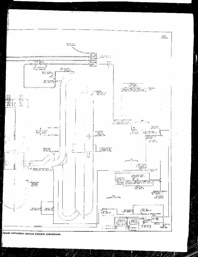
~ , ! , ,
I
.li
-r ""--LREAC.TOR
VE:S5E:L RC-T-I
level indication vers elevations. us system
I
\-/? .. Ij
'-"."{C'"I
I
I I ~CDC:6""T"~ , I i
!
>-- ._-
~~:~';~i;' ' ;;~"E"

3. EXECUTION
3.1 Containment Entries
Table 3-1 describes the accomplishments of each containment entry
associated with the Quick Look. Man-hours and man-rem associated with each task are also given.
TABLE 3-1. QUICK LOOK CONTAINMENT ENTRIES
Entry Entry Number Date Accom[21ishments Man-Hours a Man-Rem
62 5/13/82 Measured missile shield gap 2.1 0.354
62 5/13/82 Radiological survey of service 2.4 0.4 structure
62 5/13/82 Remote survey of "B" O-ring 1. 43 0.316
63 5/26/82 Remote survey of "B" O-ring 2.76 0.634
63 5/26/82 Survey of "A" O-ring 1. 34 1. 573
63 5/26/82 Walkdown of nitrogen system 1. 46 0.171
64 6/3/82 Inventory of CROM tools 1. 14 0.165
64 6/3/82 Relocated CCTV Nos. 7 and 8 to 5.19 0.533 O-ring catlvalks
65 6/10/82 Performed operational check 3.26 0.462 of the nitrogen system
65 6/10/82 Installed emergency lights on 2.39 0.298 the service structure; Tested 110/480 V receptacles on eleva-tion 347'
66 6/17/82 Staged lead tJlankets on 3.05 0.789 elevation 347 '
3-1
- , - ~ . - ~., -:- t,'
t ~. . • i . fJ _ . '" •
b

Entry Number
67
69
69
69
69
70
70
71
72
72
72
72
72
Entry Oate
6/22/82
7/1/82
7/1/82
7/1/82
7/1/82
7/8/82
7/8/82
7112/82
7114/82
7/14/82
7/14/82
7/14/82
7/14/82
TABLE 3-1. (Continued)
Accomplishments
Installed portable power distribution center on elevation 347'; Installed portable lighting on O-ring catwalks
Installed CROM work platforms
Installed hoist/trolley on the missile shields
Performed a high pre~sure flush of the "B" O-ring
Remote survey of "B" O-ring
Installed temporary nitrogen system manifolds and hoses
Remote survey of "B" O-ring
Low pressure fl ush of "A" and "B" O-rings
Surveyed SV-V-25A and SV-V-26A
Installed compound pressure gauge on the "A" loop; Connected the "B" loop to the vent manifold
Man-Hours a
2.94
1. 1Ll
3.03
4.35
1. 26
4.71
2.06
4.57
1. 14
2.85
Completed installation of service 2.26 structure emergency lighting and extension cords;T~ttempted to relocate Earmark receive antenna
Oepressurized secondary side - 3.06 nitrogen blanket and vented the "A" loop
Vented the "B" loop and the 2.67 pressurizer
3-2
b r~an- Rem
0.411
0.251
0.502
0.731
0.215
1.0
0.34
0.967
0.232
0.963
0.322
0.6
0.707

TABLE 3-1. (Continued)
Entry Entry a b Number Date Accomplishments Man-Hours Man-Rem ----
72 7/14/82 Nitrogen blanketed "A" and "B" 1.0 0.225 loops
73 7 /15/82 Nitrogen blanketed the pressurizer 0.6 0.187 and closed seconclary side valves
73 7/15/82 Installed radiation detectors 1. 06 0.174
73 7/15/82 Obtained (ROM gas samples and 4.15 0.525 initiated venting
73 7/15/82 Completed venting and obtained 5.51 0.719 CROM liquid sample
74 7/14/82 OepressUl'i zed RCS nitrogen blanket 0.86 0.18
74 7/19/82 Installed PVC leadscrew sleeves 4.85 0.753 and stageo CROM tools
74 7/19/82 Vented, uncoupled, and parked 7.61 1.193 leadscrew (first team)
74 7/19/82 Vented, uncoupled, and pal'ked 4.54 0.594 leadscrew (second team)
75 7/21/82 Removed, cut, and rigged leadscrew 6.7 1. 409 ()ff ser'!i ce structure
75 7/21/82 Replaced ?~d relocated the 2.90 0.502 Earmark' receive antenna
75 7/21/82 Obtained an RCS liquid sample 4.23 0.582
75 7/21/82 Instal led camera, video, and 3.21 0.34 recording equipment
75 7/21/82 Perfol'mecl Qui ck Look camera 5.55 1. 203 inspection
75 7/28/82 Radiological survey of sel'vi ce 0.57 0.105 stnlcture
76 7/28/82 Obtained three RCS liquid samples 3.54 0.545
77 8/4/82 Obtained an RCS liquid sample 2.16 0.268
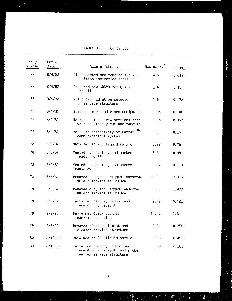
TABLE 3-1. (Continued)
Entry Entry a b Number Date Accom[!lishments Han-Hours Han-Rem
77 8/4/82 Disconnected and removed the rod 4.5 0.612 position indication cabling
77 8/4/82 Prepared six CRDMs for Quick 1.6 0.19 Look II
77 8/4/82 Relocated radiation detector 1.5 0.178 on service structure
77 8/4/82 Staged camera and video equipment 1. 05 0.148
77 8/4/82 Relocated leadscrew sections that 3.15 0.397 were previously cut and removed
77 8/4/82 Verified operability of Earmark™ 0.86 0.15 communications system
78 8/5/82 Obtained an RCS liquid sample 0.99 0.25
78 8/5/82 Vented, uncoupled, and parked 8.3 0.95 leadscrew 8B
78 8/5/82 Vented, uncoupled, and parked 6.92 0.719 leadscrew 9E
78 8/5/82 Removed, cut, and rigged leadscrew 5.06 2.316 9E off service structure
79 8/6/82 Removed cut, and rigged leadscrew 6.5 1. 933 88 off service structure
79 8/6/82 Installed camera, video, and 2.79 0.481 recording equipment
79 8/6/82 Performed Quick Look II 10.07 1.5 camera inspection
79 8/6/82 Removed video equipment and 3.0 0.358 cleaned service structure
80 8/12/82 Obtained an RCS liquid sample 3.66 0.493
80 8/12/82 Installed camera, video, and 1. 39 0.163 recording equipment, and probe tool on service structure

TABLE 3-l. (Continued)
Entry Entl'Y a b Number Date Accomplishments Man-Hours Man-Rem
80 8/12/82 Cut and removed about two-thirds 4.16 0.487 of the CROM lockwires
80 8/12/82 Performed Quick Look III camera 13.87 l. 487 inspection and core probe
81 8/13/82 Obtained gas samples from 2.43 0.273 three CROMs
83 8/18/82 Obtained an RCS liquid sample 2.0 0.243
83 8/18/82 Cut and removed remalnlng 2.0 0.242 CROM lockwires
85 8/23/82 Removed about one-half of the 4.0 0.448 CROM closul'es
8S 8/23/82 Installed acoustical monitor in 0.66 0.09 CROM 9E
85 8/23/82 Uncoupled about one-half of the 4.61 0.628 CROMs
86 8/25/82 Obtained an RCS liquid sample 2.0 0.244
86 8/25/82 Removed remaining CROM closures 5.28 0.644
86 8/25/82 Uncoupled rema in i ng e ROr~s 5.68 0.783 (except for three)
89 9/1/82 Obtained an RCS Ii qu i d sample l. 98 0.299
90 9/3/82 Installed manometer on eROM 8H 4.10 0.629 and obt3ined gas sample
91 9/8/82 Obtained an ReS liquid sample 0.9 0.134
91 9/8/82 Obtained a CROH gas sample 0.9 0.133
92 9/10/82 Obtained a CROH gas sample l. 42 0.18

Entry Number
93
93
Entry Date
9/15/82
9/15/82
TABLE 3-1. (Continued)
Accomplishments
Obtained an RCS liquid sample
Obtained a CROM gas sample
TOTALS
Man-Hours a
1.1
2.0
243.2
b Man-Rem
0.174
0.287
40.684
a Man-hours were calculated based on the sum of the individual team member's man-hours.
b Man-rem were calculated based on the sum of the individual dosimeter readinG recorded on each radiation work permit (RWP). These readings will not necessarily coincide with the TlO readings.
3-6

3.2 Preliminary Data Collected
3.2.1 Gas and Liquid Samples
Three CROM samples were obtained during entry 73 on July 15, 1982. These
samples consisted of two gas samples (one line purge sample and one system
sample) and one I iquid sample. AI! CROM samples were obtained using evacuated,
150 ml sample hombs attached tJ the CROM venting tool back-up valve. After
obtaining the CROM purge and gas samples, the CROM venting tool was connected
to the blower and ductwork assembly to dilute the remainder of the gas from the
CROM. Fol lowing the complete venting of the CROM, a (ROM liquid sample was
obtained by connecting an evacuated 150 ml sample bomb to the isolation valve
of the venting tool. Tables 3-2, 3-3, and 3-4 present the analysis results for
these samples.
Anal:isis
Kr-85
Cs-137
O2
N2
H2
Other'
TABLE 3-2. CROM PURGE SAMPLE FROM 10H CROM VENT (July 15, 1982 - Sample No. 86548)
Results Units Uneer'taint~
1. lEO pCi/cc 1. 2E-2
3. 5E - 5 pCi/ec 5.2E-6
4 %
21 %
57 o. '0
18 %
Units
IICi/cc
IJCi/ce
NOTE: Positive particulate results on Marinel Ii beakers should cnly be consider-ed as qualitat.ive.
3-7

Analysis
Kr-85
O2
N2
H2
Other
TABLE 3-3. CROM GAS SAMPLE FROM lOH CROM VENT (July 15, 1982 - Sample No. 86547)
Results Units Uncertainty
1. lEO pCi/cc 1.2E-2
2 %
14 %
63 %
21 %
3-8
Units
pCi/cc

Analysis
B
C1
Na
pH
H-3
Sr-90
Turbidity (before
f i 1 t )' at ion)
Turbidity (after filtration)
Cs-134
Cs-137
Co-58
Co-60
Ru-l06
Sb-125
Ce-144
Mn-54
Gross alpha
Gross beta
TABLE 3-4. CRDM LIQUID SAMPLE FROM 10H CRDM VENT (July IS, 1982 - Sample No. 86546)
Results LLD Units Uncertainty
3820 ppm
2.5 ppm
780 ppm
7.72
4.6E-2 pCi/ml 7
9.5EO pei/ml 35
200 NTUa 20
180 NTU a 20
2.2E-1 !I Ci / ml 1.0E-3
2.6EO pCi/ml 3.1E-3
7.0[-4 pCi/ml
9.6E-3 pCi/ml 2.9E-4
1. 8[ - 2 IJC i /m I 3.3E-3
5.5E-2 !I Ci / ml 1. 9[ - 3
2.0E-1 pCi/ml 2.lE-3
8.6E-4 pCi/ml ,'.IE-4
8.9E-3 !I Ci / ml 1.5[-3
1.47E+l IICi/ml 6.24E-2
a. NTU nonnal turbidi:'y unit~.
3-9
Units
%
%
NTU a
NTUa
IJCi /ml
pCi/ml
pCi/ml
!ICi / ml
pCi/ml
pCi/ml
pCi/ml
IJC i /ml
pCi/ml

Contact RO-2A readings on the gas and liquid samples collected were as follows:
o CROM gas samples:
Line purge: 150 mR/hour gamma and 400 mrad/hollr beta
System vent: 150 mR/hour gamma and 520 mrad/hour beta
o CROM liquid sample: 150 mR/hour gamma and 400 mrad/hour beta
One RCS liquid sample was obtained during entry 75 on July 21, 1982. The
sample was obtained using a solenoid actuated, 150 ml sample bomb which was
lowered into the I'eactor vessel through the CROM, to a depth 28 feet below the
top of the motor tube. The sample bomb was lowered into the motor tube using
four 10-foot aluminum support tubes. Support tubes were connected as required
to reach the prescribed depth and supported at that depth using a tripod
assembly. The sample solenoid was energized by a power supply brought into the
containment by the entry team. Table 3-5 presents the analysis results for this RCS sample.
RCS liquid samples were taken each week thereafter and similar analyses
were conducted. After using evacuated sample bombs several times, the sampling
technique was changed to the use of a manually operated pump that would draw
RCS liquid up a suction hose inside the CROM and discharge into a sample
container.
Ouring tasks involving the removal of CROM closures, it became evident
that gas was being generated under the reactor vessel head at unexpected rates.
Gas samples were obtained from the tops of CROMs at positions 2H, 7G, and 7K.
Analysis of the samples indicated that when a CROM closure was opened, the gas
mixture in the motor tube changed from hydrogen with an oxygen deficiency to a
mixture that had higher oxygen and nitrogen concentrations and a lower hydrngen
concentration.
3-10

TABLE 3-5. RCS LIQUID SAMPLE ANALYSIS FROM REACTOR VESSEL (July 21, 1982 - Sample No. 86798)
Anal,isis Results LLD Units Uncertaint,i Units
Cs-134 1. 9E-l /-lCi/ml 9.3E-4 IJCi/ml
Cs-137 2.3EO /-lei/ml 2.9E-3 pCi/ml
t:o-~;8 5.6E-4 pCi/ml
Co-60 1. IE - 3 pCi/ml 1.0E-4 pCi/ml
Ru-l06 1. OE - 2 pCi/ml
Sb-125 5.4E-3 pCi/ml
Ce-144 4.5E-3 IJCi/rnl
Gross be:a 9.94EO IJC i /ml 5.17E-2 IJC i Iml
Gross alpha 6.2EiE-5 !lCi/ml 4.33E-5 !lCi/ml
pH 7.71
B 3922 ppm
Cl 1.9 ppm
Na 790 ppm
H-3 4.2E-2 IJCi /ml 6.9 %
Sr-90 7.4EO /-lCi/ml 35 0' /0
TUI'bidity 14 NTU a 0.3 NTUa
a. NTU normal turbidity units
3-11

After the CROM uncoupling attempts were completed, a m~n0meter was
connected to the CROM vent tool (see Figure 3-1) that was installed on the
central CRrM (8H) (see ~igure 3-2). The gases generated under the reactor
vessel head collected in the central CRDM, where . ~ ga c bUlldup could be
measured with the manometer. The CROM ar,d manometer were intially purged with
nitrogen and gas samples were taken periodically. The analysis results of
these CROM pas samples are presertect in Taole 3-6. Observations of the
manometer indicated that gas buildup was approximately 0.04 to 0.05 cubic foot per day.
TABLE 3-6. CROM 8H GAS SAMPLE ANALYSES
Sample Sample Sample Sample Sample 9/3/82 9/8/82 9/10/82 9/15/62 9/15/82
C')nstituent (%) (%) (%) (%) (%)
N2 95.5 87.4 91. 9 89.3 86.8
H2 <0.1 6.3 8.0 11. 8 12.5
O2 4.3 4.3 1.6 l.7 l.0
Others 2.0
3-12

Contact RO-2A readings on the RCS liquid sample bomb were 100 mR/hoJr
gamma and 240 mrad/hour beta.
3.2.2 Leadscrew Information
During removal of the leadscrews, no apparent warpagE or defor~~ties were
observed. Except for the leadscrew bayonet couplings and the lead~, ,2W at
position 88, the leadscrew surfaces were clean. The bayonet couplings and the
lead~crew at position 8B were covered with a black powdery substance.
Dose rate profiles of the three leadscrews that were removed are presented
in Figures 3-3, 3-4, and 3-5.
Three leadscrew-related samples were removed from the reactor building for
analysis. These samples were:
o A scraplng sample off the inside of CRDM GB (#88905)
a A small fleck observed on the service structure after removing lead
screw 88 (#88906)
o A sample of the cutt'oIg remnants (shaving) of the leadscrews (mostly
position 88) (#08904).
The c,LrapinrJ sam[)le only consisted of several small flecks. ThE: 88
lpJJscrew sample was a single fleck approximately 1/8 inch in diameter. while
the shavings sample consisted of severdl grams of miscell~neous shavings. Four
sub-samples of each type of material were removed from the cuttings and placed
in separate ~2tri dishes. Microscopic examinations showed that portions of the
cuttings sample had the same general appearance as the scraping and leadscrew
samples.
Approximately 100 mg of the cuttings sample were tested for pyrophoric
characteristics. First, the sample was heated on a hot plate to approximately
150 C for 10 minutes in air. No spontaneous ignition was observed. However,
while the sample initially contained flecks of various sizes and colors, all
the material changed to a urliform dark gray to black color after heating.
3-13

----------------------------------------------------------............... ~
The heated sample was then exposed to a flint/steel spark source with 110
spontaneous ignition observed after several dirpct strikes. Approximately
10 mg of the heated sample were then direcLly heated with an alcohol flame for
several minutes. There was no evi~ence of spontaneous ignition. A maximum
temperature of 1000 ( was e~timated.
A small portion of the 150 ( heated sample was then placed in a petri dish
and a smJll portion of the flamed sample was placed in another petri dish, for
vi5ual comparison with the unheated samples. All eight of these petri dishes
were then examined with a 60 power microscope prior to quantitative assay.
All samples were counted for gamma and beta activities. The results are
summarized on Table 3-7. The data indicate a wide range of activities for
these samples. The (ROM scrape sample had the lowest (s-137 to Sr-gO ratio,
while the crud sample that fell off during the 8B leadscrew removal had the
highest ratio. For reference, the (s-137 to Sr-gO ratio for a variety of
samples is also given in this table. General conclusions are difficult to draw
from these data.
3.2.3 Leadscrew Uncoupling Descriptions for Drive Locations 8H and 7K
During the first attempt to uncouple the leadscrew on drive 8H, there were
indications of interferences or damage because the initial load reading was 350
pounds. The leadscrew nut rotated freely. Initially the leadscrew did not
lower; therefore, the leadscrew would not rotate. After tapping on the light
weight leadscrew lifting tool, the leadscrew lowered enough to allow it to
rotate 45 degrees to the uncoupled position.
At this point the leadscrew and tool weight should have been 170 pounds;
however, the leadscrew would not lift above 1 inch without exceeding the
administrative load limit of 350 pounds.
3-14

----------------........ ........-TABLE 3-7. RADIOACTIVITY ANALYSES OF LEADSCREW SAMPLES
Sample Number
88905a
88906
88904-1
88904-2
88904-3
88904-4
38904-heat
88904-flame
Total Activity (Ci) Cs-137 Cs-134 Sr-90
4 6E-2 3.6E-3 8.9E-3
6.2E-l 4.8E-2 2.4E-3
1. 3E-l l.lE-2 7.4E-4
2.9E-3 1. 7E-4 < 2E-4
1. 3E'-1 1. lE-2 1. 2E - 3
4.2E-l 3.8E-2 5.7E-3
3.lE-2 2.4E-3 <5.5E-4
2.4E-l 2.2E-2 7.4E-4
a. Othel' activities detected 1n this sample only:
Cs-137/Sr-90
5.2
258
176
108
74
324
Co-60 = 2.8E-4, Ru-l06 = 3.9E-3, Sb-125 = 3.7E-2, Ce-144 1.5E-3
For Reference Cs-137/Sr-90
RB sump - typical range
RCS prior to processing
RCS prior to Quick Look
Air in containment
Smears in containment
Fi ltel'able ReS
~ilterable RB sump
CRDM purge filter sample
. '.
3-15
. . -. ~ ~ . - :-
10 to 20
0.8
0.3
"'20
10 to 20
0.001 to 0.5
0.5 to 1
0.1

The 1eadscrew was raised, 101fered, and rotated for several minutes until
the decision was made to go to the next drive. During these movements of the
leadscrew it was rotated beyond the 45-degree point; later analysis indicat2d
that it was likely that the spider had fallen off. However, the interference
still existed and the 1eadscrew could not be removed.
After an unsuccessful attempt to uncouple the 1eadscrew at CROM 7K,
another attempt was made at CROM BH. The nut was rotated clockwise to the hard
stop in order to return the drive to its original position. The nut rotated 20
times in lieu of the 4 to 7 expected. This gave a positive indication that the
1eadscrew was in an uncoupled position and the nut was bottomed on the lead
screw engagement pins.
When the leadscrew was loaded it still did not move beyond the I-inch mark
without exceeding the 350-pound administrative load limit. In light of the
positive indication uf uncoupling, the operator was instructed to jar the tool
in an attempt to determine where the problem was. During this step the 1ead
screw broke loose and the load reading was 170 pounds. The remainder of the
1eadscrew parking and removal process indicated that there was no detectable
damage to the 1eadscrew.
As previously noted, after the first attempt to remove the leadscrew at
CROM 8H was unsuccessful, an attempt was made to remove the 1eadscrew at CRDM
7K. This 1eadscrew also had indications that there were interferences or
damage because of the initial load reading of 350 pounds. Although the 1ead
screw nut rotated freely, initially the 1eadscrew did not move up or down;
however, as with position 8H, after tapping on the leadscrew lifting tool, the
1eadscrew moved up, down, and rotated. The 1eadscrew was lifted after rotating
it 45 degrees, although it would not move more than 1 inch without exceeding
the 350-pound load limit.
After several up and down movements and several rotations (0 degrees to
45 degrees to 0 degrees) of the 1eadscrew lifting tool, the 1eadscrew was in a
condition where it could not be rotated with the lightweight leadscrew lifting
tool. At this point the lifting tool and nut runner were removed and the
alternate uncoupling tool (see Figure 3-6) was tried.
3-16

When the jumping jack and alternate uncoupling tool were engaged, the jack
was actuated and the torque tube (see Figures 3-7 and 3-8) was raised and
lowered normally. The torque tub(~ rotated only 30 to 35 degrees. In an
attempt to gain a full 45-degree rotation, the torque tube was rotated back and
forth several times. During these rotations it was observed that the reverse
hard stop was approximately 25 degrees behind the normal uncoupled position.
No clear conclusion could be drawn from these observations. After several
unsuccessful attempts to gain the 45-degree rotation for uncoupling, the torque
tllbe was returned to the coupled position and recoupled inside the motor tube.
At this point operations on drive 7K were terminated.
3.3 Observations from the Camera Inspections
The Quick Look camera inspections were performed inside of the TMI-2
reactor vessel on July 21, August 6, and August 12, 1982. The camera revealed
that the upper central portion of the reactor fuel has collapsed 2nd forms a
loose bed of rubble, whose upper surface is about 5 feet below the normal top
of the core. This appears to support earlier studies of the accident that
theorized severe damage in the upper central portion of the core where the
temperatures were the highest.
The first look involved inserting the camera down the space vacated by the
removal of the leadscrew drive from the central CROM. The camera showed no
visible damage to the plenum assembly above the core. However, when the camera
was lowered to the point where the control rod and fuel assembly should have
been, it was found that the core had s lumped away from the plenum. The camera
was then lowered an additional 5 feet where the top of the bed of rubble was
observed. Only a very limited part of the core could be observed during this
inspection due to water clarity and lighting conditions.
Alter removlng two more control rod leadscrew drives at the edge of the
core and at a point Inidway between the outer edge and the center, the seconrl
inspection was co: 'iuc+ed. -;-;:.~ pictures at the edge revealed that the control
)'od and the fllel assemQ1y in this position were still in place. In the pic
tures taken at th~ midpoint between the edge and the center, more evidence of
3-17

the bed of rubble could be seen. The top of the rubble at this point was also
observed to be 5 feet below the plenum assembly, as was the case at the center
position. These pictures revealed several Y'ecognizable components in the COl'e,
including fuel rod springs, intact or partially intact nonfuel beat'ing tubes,
and severa, pal'tial fuel assemblies hanging from their position in the plenum
assembly. The quality of the pictures was improved due to the installation of
a supplementary light into the center position (used for the first inspection) and possibly due to improved water clarity.
The third inspection included probing the rubble bed to determine its
constituency. A steel rod was insertp~ down the same position between the edge
and the center of the core as was used for the second inspection. The rod was
lowered until it rested on the top of the rubble. It was then pushed into the
rubble with relatively little force for a distance of 14 inches, indicating
that at least the top layer at this point is loose rubble. The probe test was
then conducted at the center of the core, where it was also found that the
upper 14 inches of the rubble bed is loose material.
Several preliminary conclusions have been made based on a review of the camera
inspections. The initial conclusions are limited only to areas explored by the camera:
o A significant portion of the Unit 2 fuel assembl~es was severely
damaged during the 1979 accident, wIth the result that some of them
are in a bed of rubble.
o An approximate~y 5-foot-deep void exists in the upper portion of the
core, extending from the core's center line about halfway to its edge.
a No evidence of melted fuel pellets was found; however, no generalized
conclusions have been made on whether or not any of the fuel pellets
within the core had melted.
a At two points, one at the center and the other midway to the edge, the
rubble at the bottom of the void is composed of loose material to a
3-18

depth of at least 14 inches, and 1n those two al'eas the rubble is not
a fused mass.
a As expected, there appeared to be evidence of partial melting of
Ilollfuel matel'ial, such as metal components that have melting points
much lower than uranium oxide fuel.
a The plenum, a maJol' l'eactol' component just above the core, appeared to
be substantially undamaged. At a point between the center and the
periphery of the core, parts of fuel assemblies were seen hanging from
the lower plate of the plenum.
A committee, the Qllick Look Tape Review Group, which was composed of
individuals \,/ho \'iel'e familial' with the detail c, of the cOllstruction of fuel and
COI'e intel'nals, and wi til virJeo tectlnology, reviewed the videotapes. The
details of the Quick I.ook Tape Review GI'OLIp conclusiolls can be fOLind in their
l'epol't, Data f<epol't - Quick Look~ection Results (rPO/Tt~I-026), f)ecember 1982,
GPU Nuclear Technical Planning Department. lhe fol lowing sections are a brief
sunlr.lary of sume of the obsel'vat iOI1S ft'om the ,'epoft.
3.3.1 OlJsel'Ve(~ Conditioll of the Plenum
The interiol' SIll laces of t.he CRDr~ guide t.ubes (8B, 2H, and 9E) were
tllOl'oucjhly examined and apP"di'ed to be iii (Jooj condition. Neal'ly all of the
:.et,>cl'ews, \>Ihich fast.en tlw Ljllirle tubes to the tJI'azement support p'lates, we)'e
iocate>d. illl sc,'ews had clea l lj vi:.ible, intact threads. Val'ying amounts of
fine "udace deposit c., as ,'IP11 dO, some small flakes, v.e)'e olJservecl on the top
sudace OT tlte SCI'hiS. All SUppOI't plates inspected v/el'e UIlIH'oken, free of
cJistOI'tioll, 3 III I generally lIndamaqed, althollCjh the top sudaces were covered
\'Iith layel's of flake' 3t evel'y locat.ioll ilbpecLed. The junctions of the
support plates with the C-,tul)es and spl it tubes appeared to be normal with no
evidence of meltin~J. TIlt-' i>oLtOITI end of Olle of t.hE' split tubes at the 9E
ioc<ltioll showed evidence of millLl' wastacJe of metal. Some of the nearby C-tubes
also showed si~Jlls of rneltincJ 1)(=-10\<1 tile tenth support. Other C-tubes only
cent imeters away at. 9E wel'e uiH.lc:maCjecl.
3-.i 9
-.-
: : .,- ~ "~'. . • - -:, I • . , - •.. _ .: P/ . '~"; 1..: .. '~f ,o~t -)~·~i·~: -.: ·i,~;.;~~I~·.~ .•

Since markings on the camera cable allowed the depth of the camera lens to
be known to within 1 inch, it was possible to determine that the grid plate had
not sagged at any of the three locations examined. The brazement support
plates, ends of the C-tubes and split tubes, grid plate surfaces, alld pressure
pads were all found in their normal locations.
At location 9E, the fuel element upper end fitting and the three adjacent
upper end fittings (80, 8E, and 90) were suspended from the underside of the
grid plate. The grillage was completely missing on the 9E upper end fitting.
The spider, spring, and spring retainer were also missing. The grillage on
the other three visible upper end fittings was present, but partially damaged.
One of the upper end fittillgS had other identifiable components suspended from
it. A spacer grid, stubs of control elements, and partial fuel pins were visible.
The 9E upper end fitting was scanned from inside with the right angle lens
and appeared to be in its normal position with respect to the grid structure.
Metal chips and debris were found in the tight space between the center tabs on
the end fitting and the grid. This debris may be what is holding the end
fitting in place, although the remainder of the fuel element was missing. Some
areas of the 9E upper end fitting look like metal that has been cut by a torch,
while adjacent areas appear to be in the as-manufactured condition.
3.3.2 Distribution of Core Debris
Flakes of debris 1/8 inch in diameter or less were observed on nearly
every horizontal surface. The thickest layer of flakes seen was not more than
1/16 inch in depth. These layers were loosely deposited, since the motion of
the camera in the water often disturbed the flakes.
Each support plate observed in the CRDM guide tube at location 9E had a
layer of flakes, whose thickness increased with depth, on tht:: top surface. The
undersides of the horizontal surfaces were clean and free of loose debris.
Vertical surfaces were clean and free of loose debris. Vertical surfaces of
the CRDM guide tubes and C-tubes were relatively free of debris near the top of
3-20

the plenum, although some slight deposit of mat~rial was evident as the c~mel'a
was lowered.
Debl'is of lal'ger chal'acteristic :,ize was lodged III Lhe na,Tow space
between the uppel' end fittincJ centel'inq tabs and the plenum Wid plate. This
debl'is appeal'eel to be metal chips 01' fl'agrnents, I'ather than tiny flake,. One
piece of deb"is looked like d fuel pellet fl'agment.
\1henevel' the camera impacted lhe rubble bed, a cloud of "(,I'y fine pl'r'ti-
cles, which settled 01' dispersed quickly, was generated. The tUl'bidity of the
l'later val'ied from one camera inspection to the next. Durin~J the first camera
inspection, the water was qllite cloudy with visibility limited to 3 inches
tJeyond the camel'a at most. The visibi lity increased to about CJ inches beyond
the lens C1UI'ill~J the securld CCilllel'a inspection; however. it appeal'ed that V1Sl-
t Ii i r cJ cam e I' a ins p e c t i U II, a va i I a b I eli g h L c1 I so -3 P pea led tab e the fa c tor lim i t -
illl) ,/isibility, causinq ubjects to be illCJistirlCt, althoucJh disce,'r~ibie, from 1
0" 2 feet beyond LllE' call1('I'CI.
3.3.3 ~xtenl of Core Damage
A void exists in tile upper central pOl'tion of the co!'('. At posilion 8H,
the center' of the COl'e, the vIJid extencJs fr'orn the bottom of the plenum to a
rubble beG, the t.up "·lJl'tacp erf I"hicll is ~) feel beluv, the bottom of the plenum.
This voicJ illcludes aL ''''elst t.he central nine fuel localions. At the 9E loca
tion, the JJic! .'1h,) t'.xtelili c ~, teet !Jeluvi the lowe" sudace ot tile plenllm. It
I'd" not jJvsii)l,::, tu l'utatE' till::- '.Jllll::'l'a ~6CJ elegrees, To \'1.10, clone at lJosition SH.
since the C.dllll::'l'r] W·jC' pl'eve.' tJli tram tlll'liincJ Gil every attempt. Stllbs of )'ods
wel'e seel' extendinCj LI,)\'lanj ftum the t'ulJble at pvsition St. Rucj stubs vlel'e also
o b s e I' 'J e ~ ; i 1 a n CJ i II!.J do \\111\-, a i ,j a i c· II CJ the , .. ",.; t e cl CJ e 0 f ttl P c.. 0 I' e a t tilE:' (; 0 I 0 c OJ t ion.
fhej "Ie)'e stlspended l'li!i1 tile remains 1)1 the uppel end fitlinCj, "II,ich vIas still
in placE'.
At position 8H tlw el1lill~ uppel' end filtinCj was missing, as Ivas an adjacenl
one. At positions cG, 8E, 9[, and 9E, the lipper' end fittings were still
sLispencJed fY'om the plenum cjl'ic, plate. 1he sIJicJe)' assemblies were encollnter'ed
3-21
I I
in theil' normal positions at location 88 and one adjacent location, which
indicates that the fuel bundles in these locations wel'e sufficiently intact to
support the spiders.
3.4 COI'e Pl'obe
The l'ubble bed was probed by inserting a 1/2-inch-diametel' steel I'od int.o
the reactor vessel thl'ough the 8H CROM guide tube unti 1 it. t.ouched t.he l'ubble.
It was then rotated and allowed t.o penetrate the debris by the force of it.s own
\oJeight (about 30 pounds). The probe easily penetl'ated t.he debl'is t.o a depth of
14 inches, where it \oJas stopped by an unyielding obstruct.ion. The I'od penetl'ated
the debris to the same depth at. location 9E.
3.5.1 Description
CROM uncouplinq and COl'e mappin~l vlel'e planned to ot)tain t.he eal'liest
possible data on the condition of the CROMs. The uncouplinCj consisted of a
series of opel'ations t.hat. att.empt.ed to disconnect dl'ive mechanism leadscl'ews
fl'om core cont.rol elements. The goals of Lhese opel'ations wel'e Lo:
o Obtain data that. can be used to assess t.he condition of t.he core
a Uncouple CROr~ leadscl'e\oJs fl'om contl'ol l'od assembl ies La pennit lead
SCl'ew pal'king and CROM I'emoval (if I'equil'ed)
o Obtain data on the condition of individual CRDHs in Ol'del' Lo develop
the most efficient plan for continqency uncouplinCj ami pal'king.
The uncoupling sequence was set up t.o obt.ain SIX majol' data items aild any
associated data t.hat may be pel'tinent to the data evaluation pl'oce::.s. These
data consisted of four pressure gauge readings taken from 3 hydraulic pressure
gauge on the jumping jack tool, the E"xtent of leadsCl'ew I·otat.ion, and whet.her
or not the hard stops were felt by the opel'ator. Other information, stich as
3-22
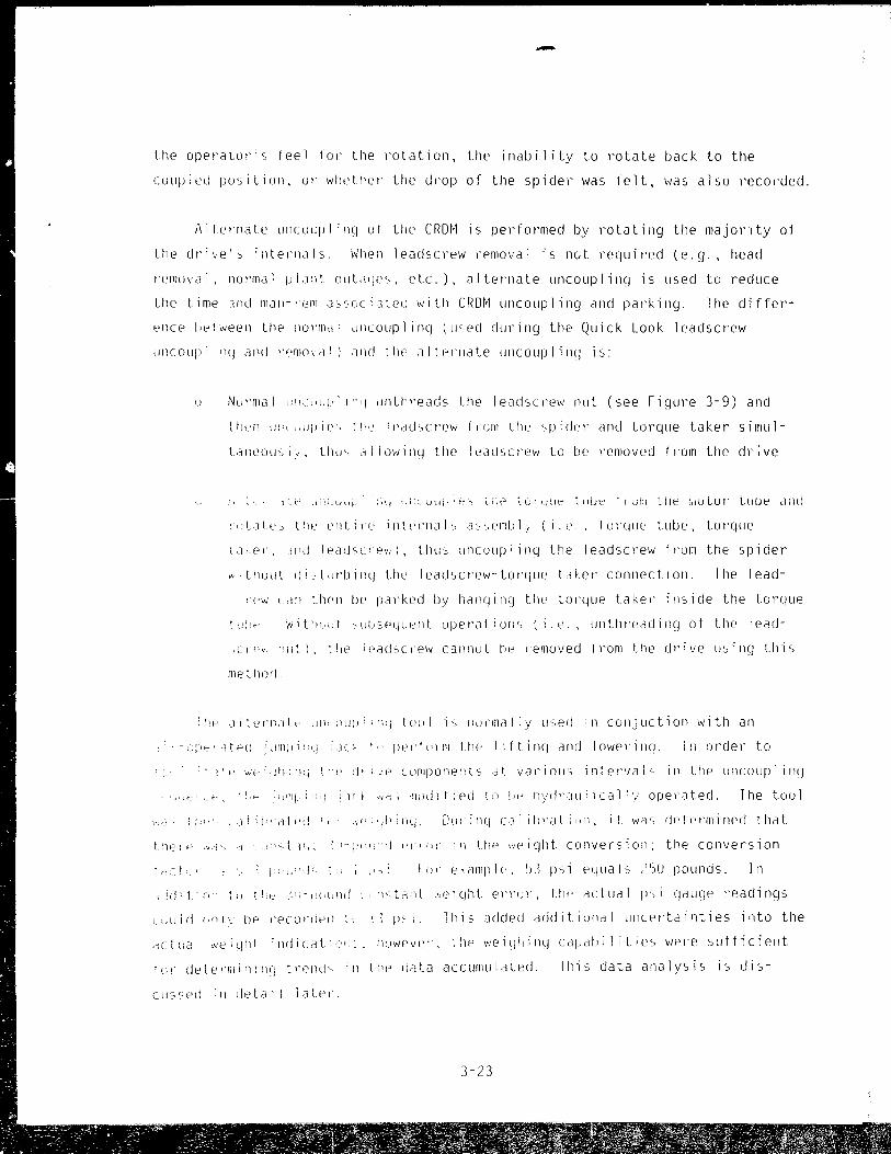
-
the opel'alol"s feel tal' the rotation, the inability to I'otate back to the
couplt:'d position, 01' 1'i/1eli'el' the cll'OP of the spidel' \Vas felt, \Vas also recol'cled.
iliLel'llate lI11coLplinCj of the CRDH is pedormed by l'olaling the majol'lty of
the Llri\e'" intel'llals. I'/hen leac!scl'ew l'pmoval is not requil'ed (e.g., head
l'emoval, nlwmal pia:',! oulaljE's, etc.), altel'llate uncouplincJ is lIsed lo reduce
the tim e 111 tI III a w : iJ In a" s c, ( i3 tee w i l heR 0 r~ un C 0 u P lin 9 and p a I' kill ~J . The d iff e t'-
,,'ncE' I,t't\veen Lhe ilOl'llldl ,1I1(Oupl inC) (lised cJlIT'ing the Quick Look leacfscl'e\V
uncoup) 'll) alll! l'pmoVe)f) JI1C! tlw Jlterllate UllCOLJplilH) is:
1I NUl'Illal 1:I!cl'L,!;' 1'1'1 llllU'I'eaus the leadscl'e\'.' 11LIL (see Fi~Jul'e 3-9) and
th"ll II: t ,dlpie', \1,", IpaclsCI'el~ flcm tilt:' spidel' and lorque taker sirnul
L:1l1eous I .. , Lilli'> d i ! O\-I i Ill) tile i t:'aLlscrelv to be l'emoveu fl'om the dl'; ve
'(IUlt'" tilt' t'lltilf' intf'l'nah a"c.emIJlj (i.e" tOl'CjllC' tube, tOT'Cjue
\ akel' .lItt! 1 eachcrev;), Liluo lInCUlip Ii Ilq Lile I eacfscl'evl f I'om the spider
"tllUlit IliLlrlJillq tilt:' leaclscl'ewLorqlle tdkeT' connection. The lead-
,'t", Cd'l lhen IJe pal'ked by hanq i Ilq the L01'ljUe takel' illS i de Lhe torque
tt.I:'" ',.;it')"d "lIIISf'ljL,i,'ltt, operatiollc, (i,e" lIl1till'eadincJ of the lead-
,(I't'\., 'liit), ~!ie ieaciscl'el'l callnuLlw lemoved Il'om Lhe ul'ive using this
me tI)J)J!,
:'ll" ditl'l'nJte c11<'1LiI': ;"'i toul h ihJI'mal:y lIsed ill cUlljuctioll with an
, -" I' f::' '1 t P ( ! ,;: Jill I) i :: (I i ,le ~ l)to I ' ! C' 1 III til f' 1 i f tin Cj and I 0\'1 e l' i 11 CJ ' III 0 r d e r t 0
• rtf' >'iI";'JI1"1(i tl p (I' i .:(' (LlfllpOnf>!lts dt variolls iflteT'ljal~ ill the lIncollpl illCJ
.' ":' ,,_,' • 'd- . :,J'lll ; "'.) : H f w!; .null i t i ell t () i,,_' !lyrll':I LI ! i cal I~.: ope l'a ted. The tuo 1
\',,1 t!"",!~i!-atp.j It "Y'ihil!lj, DlJIillCj caiii)t'ali"r'" it was rJetel-minec! that
UlPl" ,',j, "t ll,~ :-I;I1!:":I 1'1':"1- iii Uif.' \·/piC/ilt. cOllverc.io!',: the cOllversion
I,<t, ! (J! e, a In pIe, 'd p S 1 e q II a 1 s ,Jrj 0 po Ull d S , III
, :.J i t. 1 n' 1 i) t! '_' 1 , , - 11 i L Ii) d ; i ,,::; t ,", IlL .'; (' 1 q Ii L e 1 T I, !', the act U a 1 IE 1 CJ a u CJ e )' e a din CJ S
i,.L)ic! In!, IJe l'ec:oI'ued L ') p~i. lhis 3cJclecj additional ullcertai(lties into the
d_tLJ.j: ",,,,iqllt illdi(,:,lli", , !-"J\'iF'vel, ltit' l'il?iqilillCJ cal,aLliiities \'Iel'e sufficiellt
l'A lfetE'I'll1i'li(1Cj tl'OIlLi'" ;11 ll'e ,iilta acclIlIllilatecf. This data allalysis is dis-
cI;sseLi ill detai 1 late)'.
3-23

Another major pOl'tion of data accumulated relates Lo the rotation of the
leadscrew. These data were determined based on the design of the bayonet
connection between the leadscrew and spider. This connection is a flat bayonet
with no J-slots. There are four male tabs en the leadscrew and four female
slots in the spider's coupling. There is a 2-inch engagement length between
the tabs and slots which, when mated, allows very little (less than 5 degrees)
relative rotation. The characteristics of the rotation of this coupling are
discussed in detail later.
APSRs were also uncoupled using the alternate uncoupling method. Because
the leadscrew's weight is supported by the APSR roller nuts, the weight indica
tions throughout will be different than shim safety drives. The majol' difference
between APSR and shim safety drives stems from their function in the reactor.
Because the APSRs never SCI'am, their torque tubes do not have belleville
springs and their roller nuts and leadscrew are always engaged. Different
bottomed on the torque tube during insertion tests. For the remaining seven
APSRs, there was sufficient clearance between the torque tube and torque take~
to allow the torque tube to be lifted and alt~rnate uncoupling to be performed.
For APSR leadscrew parking, the stators ~ill have to be energized to
~ithdraw the leadscrew from the constraints of the spider's coupling (approxi
mately 2 inches). Once this has been pel'formed, the APSR leadscrews can be
parked manually by rotating the torque tube ~nd leadscrew using the alternate
uncoupling tool. This method requires 168 revolutions of the torque tube (fOl'
drives with the APSRs in the fully inserted position). Stators could be used
to park the leadscrews; however, without stator cOG'ing water the risk of
overheating is possible. In run speed, it takes 44 minutes to drive the
leadscrew to the park position. During the APSR insertion tests, cooling water
was not used. To part the shim safety drives, the leadscrew is engaged usi~g a
leadscrew lifting tool and the leadscrew is lifted through the roller nuts.
Additional information concerning leadsc~ew parking will be discussed later.
3-24
----------------------.............. . I

3.5.2 Data Explanation
The fil'st qauqe l'eadinq was taken after the lift of the entire assembly.
fhis included the control rod assembly, leadscrew, torque tube, torque taker,
and llncouplinq tool. Their combined weiqht was 390 pounds. For a normal drive
(the assembly moved up freely and the entil'e control l'od assembly wa; pl'esent),
this pl'essure reaclinq should have been approximately 75 psi. Since combina
tions of c!'lld l~lIilciup and mi~,sing cnntrol elements could also cause a nOI'mal
l'eadincJ (75 psi), Ue cllmlJillcltion of "II readinqs am; rotations was the only
way of detenni:lill(J a tl'uly Ilor'mal assembly uncoupling. It should also be noted
t.hat if the fil'sl CJCluCJe l'ead;ncJ exceeded about 90 pSl, il indicated that the
belleville springs were beinci compressed in onler to gain the upward torque
tube Illotion required.
1)1';01' Lo l'etation of the asspmbly. The vertical position of the torque tube
WdS just below its seated ~l~ition for this readinq. Again, for a normal
assernl)i\ tl1i, readil 1 CJ should ha.lp been aboul 7:) psi. However, if the leadscre'tl
,)1' spicier welt, st.uck (and thus lheir weiCJhl was belllCJ sllpp()"led in the drive 01'
t,y the cOl 1 lrol l'od pin damaCJe), the second I'eaclillCJ sholild have been aboul
28 psi. T hi') L 0 i'T e s po ncl e cI tot h e Ive i CJ h t 0 f the a I t ern ate un co up 1 i n g tool a '1 d
th,' tllrqup lube. If the lealiscrel'l \~as stuck it was still possible for tbe
tOI'que lube lo slide clown the leadscre'tl.
'Ile lhil'd qauge l'eMling was takel1 after I'olation of the assembly. The
vel'lical :,()',itiofl uf the torque lube \,as Ule same as for the second reading.
This I'e'lcling determined if the contl'oJ I'D" assembly 01' any weight dropped off
lhe leacl c c)'pw. K 110rmal uncnupl i!ll] w(ju~(j have a gauge reading of about 52 psi
al this poinl. III l:Cl,E''=' wjlE"'E' U" 1 v the spi del' assemb ly may lio'le beef' present,
Uw ill'IT of iii to IS ilDullels (equi'.,llenl tel ~. t.o j pSl 011 the nydraulic gauqe)
was undeteclal)le, ·:jut:' tLI tile-leU1iCily ,,f till" lCdelmeasuJ'illg device.
The fourth gauCJp I'eaelin(j was ~ab''l after thE' leadscrew and tOI'WIE' tlJile
we!'e lifted a!lel Pl'lOI to rec()uplinq the tl>rque lube to the molor lube. For a
nOl'01al dl'ive lincouplinlj, thi'; 1'(,,3(1':1(1 should also h,we been 53 psi. Thel'e w!::'re
sevel'al dl'ivC'lc. which lIl1coujJll'd (a., indicaled by the leadscrew rot-ation and/or' a
3-25
i I
I

dl'op in ,."eight indication) but requil'ed Illore than 53 psi to lift the assembly.
This increase in load seems to be a result of the saille types of interferences
that \."el'e detected clLJI'ing Quick Look I and P Ul1Co'.Jpl ing and pat'king. These
higher readings are used to identify potential parking problems at CROM loca
tions.
It should be noted that vertical downwal'd movement- of the tOI'que tube was
1 i mited to 5/8 inch duri ng the uncoup 1 i n~J attempt.
There were four different rotational conditions that were observed during
CRD~' uncouPling: (a) no I'olatiol', (b) I'olation back and rodh with han! stops
at app",'lima~E'ly -10 and +55 degl'ees, (c) l'ot2tion to the uncoupled position
with no further rdation back or fOI'th, and (J) 360-degree rotation.
o The three drives that did not uncouple fall into the categ,ry of no
rotation; however, this is representative of the clearances built into
the torque tube, torque taker, and leadscl'ew illterf3ce.
o A continued rotation back and forth with had stops indicates that U,e
spider (and possibly the control rods) did not move down after uncou
p ling.
a Rotation to the uncoupled position witb no fudhel' rotation back 01'
fOl'th indir,ted that the spidel' (and possibiy the contl'ol l'ods) moved
down greater than 0 inches and less than 2 inches. The inability to
I'otate back and forth was 1 ike 1y raused by the i nledel'ence of lre
male tabs of the leadscrew bayonet and the female slots of the spidel'
hub. i\ nOI'mal uncullpling would Cjive tl,i" indication, I)ecause the
spider would fall and be supPol'tee! by the em! fittinCj. However, this
I'otational indication. ill adciitio!l to the nOI'mal luCid reaclir'qs, VIOl:":
be I'equired to cleal'l; identify an L11lc!arnacjet! CROt·,.
o Finally, the 360-deCjl'ee l'otatiol' indicated that tile spidel~ dl'oppecJ
weateY' than 2 inches. This indication was verified by the uncouplinCj
of the 8H and 9E leadscrews during Qllick Look 1 and II followed by the
3-26

subsequent camera inspections. This indication does not verify that
the spider dropped into the core, only that it dropped greater than
the 2 inches required to clear the tabs of the leadscrew and spider
hub.
The remarks section of the data sheet was used to report unusual types of
information, such as a stuck torque tube support ring, the operator's opinion
of how the rotation of the leadscrew felt (compared to other B&W plants and
training facilities), and clues as to w~at may have caused the indications that
were recorrled. In most cases, these comments were real time assessments of
\olhat the data indicated.
3.5.' Results of Leadscrew Uncoupling Activities
The following summary of results categorizes the data into more usable
infol'mation
Based on analysis of the data obtained during leadscrew uncoupling, there
are several categories into which the leadscrews can be gl'ouped (t.le categories
are not mutually exclusive).
o Locations where the control rod spiders never moved up or down (see
Figure 3-10).
o Locations where the spiders moved down less than 2 inches after
uncoupl'ng (see Figul'e 3-11).
o Locations where the spiders moved up when lifted, but did not move
down aftel' l'ncoupling (see Figure 3-12).
o Locations where the spiders dropped greater than 2 inches after
uncoupling (see Figure 3-13).
o Locations where the leadscrew has been uncoupled but parking the
leadscrew may be difficult (see Figure 3-14).
3-27
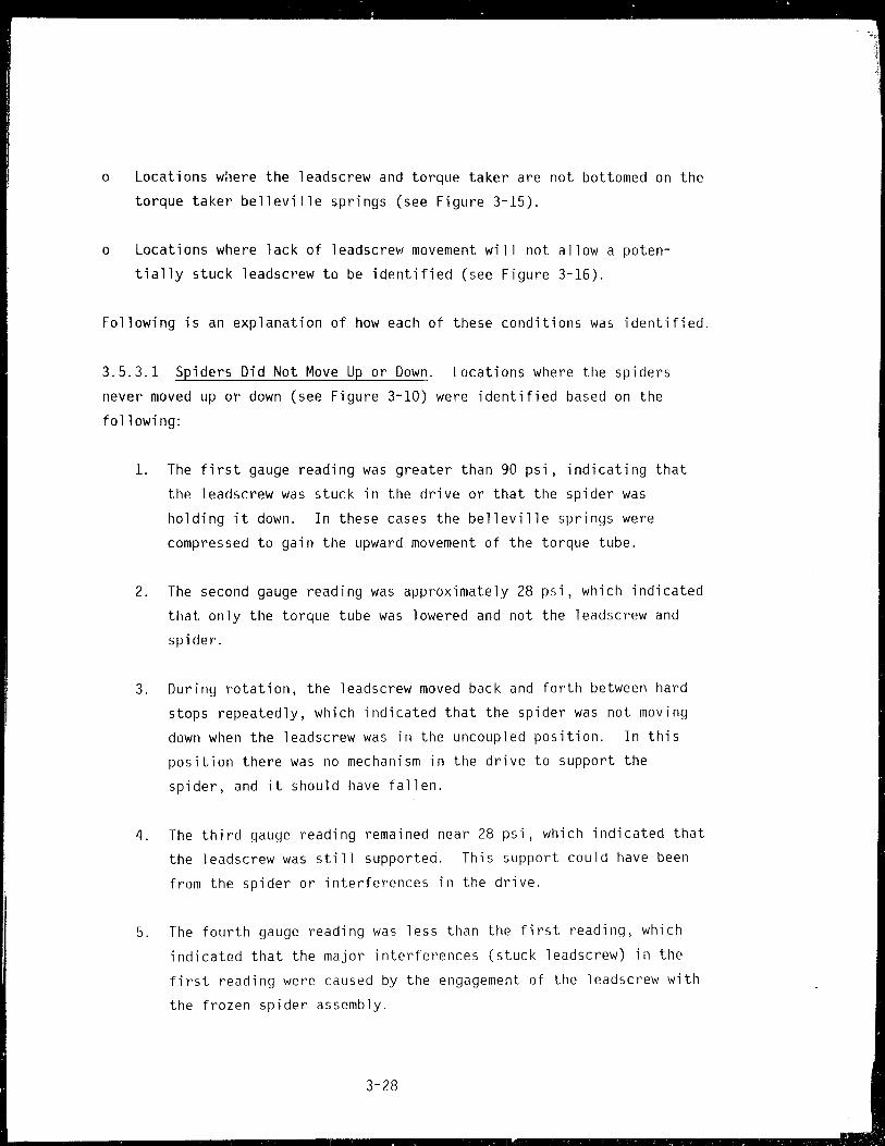
o Locations W:lere the leadscrew and torque taker are not bottomed on the
torque taker belleville springs (see Figure 3-15).
o Locations where lack of leadscrew movement will not allow a poten
tially stuck leadscrew to be identified (see Figure 3-16).
Following is an explanation of how each of these conditions was identified.
3.5.3.1 Spiders Did Not Move Up or Down. Locations where the spiders
never moved up or down (see Figure 3-10) were identified based on the
following:
1. The first gauge reading was greater than 90 psi, indicating that
the leadscrew was stuck in the drive or that the spider was
holding it down. In these cases the belleville springs were
compressed to gain the upward movement of the torque tube.
2. The second gauge reading was approximately 28 psi, which indicated
that only the torque tube was lowered and not the leadscrew and
spider.
3. During rotation, the leadscrew moved back and forth between hard
stops repeatedly, which indicated that the spider was not moving
down when the leadscrew was in the uncoupled position. In this
position there was no mechanism in the drive to support the
spider, and it should have fallen.
4. The third gauge reading remained near 28 psi, which indicated that
the leadscrew was still supported. This support could have been
from the spider or interferences in the drive.
5. The fourth gauge reading was less than the first reading, which
indicated that the major interferences (stuck leadscrew) in the
first reading were caused by the engagement of the leadscrew with
the frozen spider assembly.
3-28

3.5.3.2 Spiders Moved Down Less Than 2 Inches. Locations where the
spiders moved down less than 2 inches after uncoupling (see Figure 3-11)
were identified based on the following:
1. The first gauge reading was less than 90 psi (75 psi is normal),
which indicated that there were no significant interferences and
the leadscrew was moving up.
2. The second gauge reading was about the same as the first, which
indicated again that the assembly was moving lip and down without
interference from below. As this reading approached 53 psi it
could be assumed that large portions of the control rod assembly
were missing; however, this determination was not as positive as
others because of inaccuracies in the weighing system.
3. During rotation, the leadscrew rotated to the uncoupled position
and could not be rotated back or forth, which indicated that when
the leadscrew was rotated to the uncoupled position the spider
dropped off the leadscrew and was supported 0 to 2 inches below
the leadscrew rotating position. In this position the spider
coupl illg and Jeadscl'ew were interlocked and the spider was supported
by something (e.g., the end fitting). If an undama~2d drive was
uncoupled with this equipment alld procedure, this condition would
be expected.
4. The thil'd gauqe l'eadincJ should have been in the )'anqe of 53 psi,
which would illdicate that the leadscrew was not supported from the
spider (0)' drive).
5. The foudh gauge readinu should have been the same. If the
readiflCJ Vias highel', lhi:, cuuld have been atti'ibutec! to interfer
ellees inside the dl'ive mechallism since the spidel' dropped down
when uncoupled.
3-29

3.5.3.3 Spider Moved Up When Lifted but Did Not Move Down When Uncoupled.
Locations where the spiders moved up when lifted, but did not move down
after uncoupling (see Figure 3-12), were identified based on the following:
1. The first gauge reading was greater than 60 psi and less than
90 psi, indicating that the leadscrew was lifted but the belleville springs were compressed.
2. The second gauge reading (although not important for the overall
conclusion) gave additional information. If the reading ~as
greater than 53 psi, the entire assembly was lowering. If the
reading was about 28 psi, again this indicated something (e.g. ,
the spider) was supporting the 12adscrew weight.
3. During rotation, the leadscrew rotated back and forth between the
hard stops repeatedly, which indicated that the spider did not
drop when the leadscrew was in the uncoupled position.
4. The third gauge reading was the same as the second, which indi
cated that nothing had changed due to rotation.
5. The fourth gauge reading was the same as the first, which indicated
that the interferences were in the drive; or the gauge reading was
less than the first, which indicated that some interferences were
lost when the leadscrew was uncoupled from the spider.
3.5.3.4 Spiders Dropped More T~an 2 Inches. Locations where the spiders
dro~~Qd more than 2 inches after uncoupling (see Figure 3-13) were identi
fied based on the following: during rotation the leadscrew rotated
greater than 55 degrees, which indicated that the spider had fallen away
and therefore there were no hard stops. This indication was verified at
locations 8H and 9E during the Quick Look CRDM leadscrew uncoupling and
removal.
3-30

3.5.3.5 Uncoupled but Leadscrew May be Sticking. Locations whe~e the
leadscrew has been uncoupled but future parking of the leadscrew may be
difficult (see Figure 3-14) were identified by the following:
1. The t:rst gauge reading was greater than 75 psi, which indicated
that some interferences existed or the spider was stuck.
2. The second gauge reading was around 28 psi, which indicated that
the leadscrew was not lowered.
3. During rotation the leadscrew was rotated to the uncoupled posi
tion, which indicated that it was uncoupled from the spider.
4. The third gauge reading was around 28 psi, which indicated that
the leadscrew was still supported.
5. The fourth gauge reading was greater than 60 psi, which indicated
that the force required to move the leadscrew up was greater than
350 pounds (the design capacity of the leadscrew I ifting tool).
3.5.3.6 Torgue Takel' Not Bottomed on Springs. Locations where the
leadscrew and torque taker were not bottomed on the torque tube belleville
springs (see Figure 3-15) were identified by the following: all four
gauge readings were approximately 28 psi, which indicated that the bottom
of the torque taker was a minimum of 3/8 inch above the top of the belle
viI Ie springs. This indication ~as verified by the gauge readings of APSR
uncouplings. In the case of APSRs the leadscrews were held in this
pos it i on by the CRD~' roll er nuts and the on ly componellt 1 i fted and lowered
was the torque tube (i.e., 28 psi). Because the leadscrew rotation on
these dr'i'Jes indicated that the spidel' was still present, it was concluded
t.hat somethinCj was holding the spidel' (and cOlltrol l'od assembly) greater
than 3/8 inch higher than the (RDM scram position. The exact height of
the leadscrew was not know!l, although it could be determined by placing a
dipstick in the top of the motor tube and measuring the distance from the
top of the leadscrew to the top of the motor tube.
3- 31
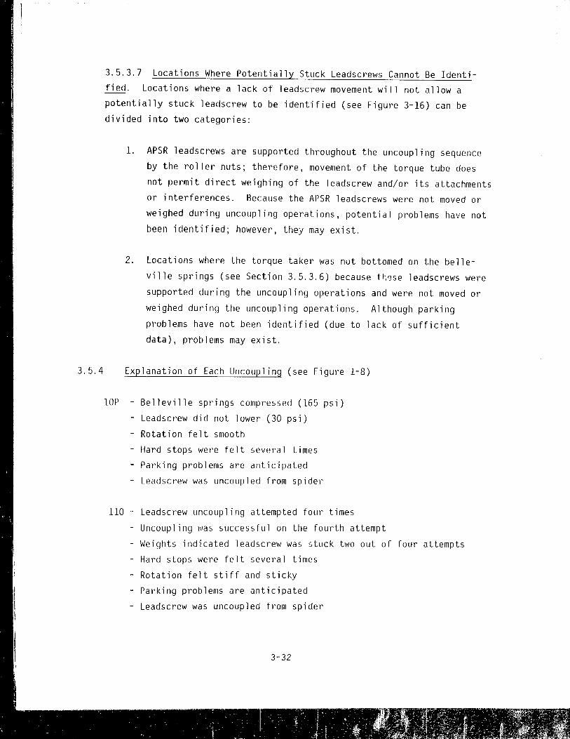
3.5.3.7 Locations Where Potentially Stuck Leadscrews Cannot Be Identi
fied. Locations where a lack of leadscrew movement wi 11 not allow a
potentially stuck leadscrew to be identified (see Figure 3-16) can be
divided into two cntegories:
1. APSR leadscrews are supported throughout the uncoupling sequence
by the roller nuts; therefore, movement of the torque tube does
not permit direct weighing of the leadscrew and/or its attachments
or interferences. Because the APSR leadscrews were not moved or
weighed during uncoupling operations, potential problems have not
been identified; however, they may exist.
2. Locations where the torque taker was nut bottomed on the belle
ville springs (see Section 3.5.3.6) because t~~se leadscrews were
supported during the uncoupling operations and were not moved or
weighed during the uncoupling operations. Although parking
problems have not been identified (due to lack of sufficient
data), problems may exist.
3.5.4 Explanation of Each Uncoupling (see Figure 1-8)
lOP Belleville springs compressed (165 psi)
- Leadscrew did not lower (30 psi)
- Rotation felt smooth
- Hard stops were felt several times
- Parking problems are anticipated
- Leadscrew was uncoupled from spider
110 - Leadscrew uncoupling attempted four times
- Uncoupling was successful on the fourth attempt
- Weights indicated leadscrew was stuck two out of four attempts
- Hard stops were felt several times
- Rotation felt stiff and sticky
- Parking problems are anticipated
- Leadscrew was uncoupled from spider
3-32

12N - Leadscrew uncoupling attempted four times
- Belleville springs compressed four times (168 psi average)
- Leadscrew did not lower four times (31 psi average)
- Leadscrew did not rotate
- Leadscrew was not uncoupled
- Parking problems cannot be identified due to lack of data
- Damage could be between CRDM and leadscrew or between the
leadscrew and spider
13M Belleville springs were compressed (190 psi)
- Leadscrew did not lower (37 psi)
- Hard stops felt several times
- Rotation felt smooth
- Parking problems are anticipated
- Leadscrew was uncoupled from spider
14L Belleville springs were compressed (190 psi)
- Leadscrew did not lower (29 psi)
- Hard stops felt several times
- Rotation felt smooth
- Parking problems are anticipated
- Leadscrew was uncoupled from spider
14H - Torque tube and leadscrew were moving up and down
- Control assembly weight less than normal
- Spider did not move down when uncoupled
- Rotation felt smooth
- No parking problems are anticipated
- ~eadscrew was uncoupled from spider
13K - Tot'que tube and leadscrew wet'e moving up and dowli
- Control assembly weight less than normal
- Spider fell less than 2 inches when uncoupled
- No parking problems al'e anticipated
- Leadscrew was uncoupled from spider
3-33
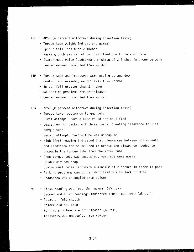
12L - APSR (4 percent withdrawn during insertion tests)
- Torque tube weight indications normal
- Spider fell less than 2 inches
Parking problems cannot be identified due to lack of data
Stator must raise leadscrew a minimun of 2 inches in order to park
- Leadscrew was uncoupled from spider
11M Torque tube and leadscrew were moving up and down
- Control rod assembly weight less than normal
- Spider fell greater than 2 inches
- No parking problems are anticipated
- Leadscrew was uncoupled from spider
ION - APSR (0 percent withdrawn during insertion tests)
- Torque taker bottom on torque tube
- First attempt, torque tube could not be lifted
- Leadscrew nut backed off three turns, creating clearance to lift
torque tube
- Second attempt, torque tube was uncoupled
- High first reading indicated that clearances between roller nuts
and leadscrew had to be used to create the clearance needed to
uncouple the torque tube from the motor tube
- Once torque tube was uncoupled, readings were normal
- Spider did not drop - Stator must raise leadscrew a minimum of 2 inches in order to park
- Parking problems cannot be identified due to lack of data
- Leadscrew was uncoupled from spider
90 - First reading was less than normal (65 psi)
- Second and third readings indicated stuck leadscrew (35 psi)
- Rotation felt smooth
- Spider did not drop
- Parking problems are anticipated (65 psi)
- Leadscrew was uncoupled from spider
3-34
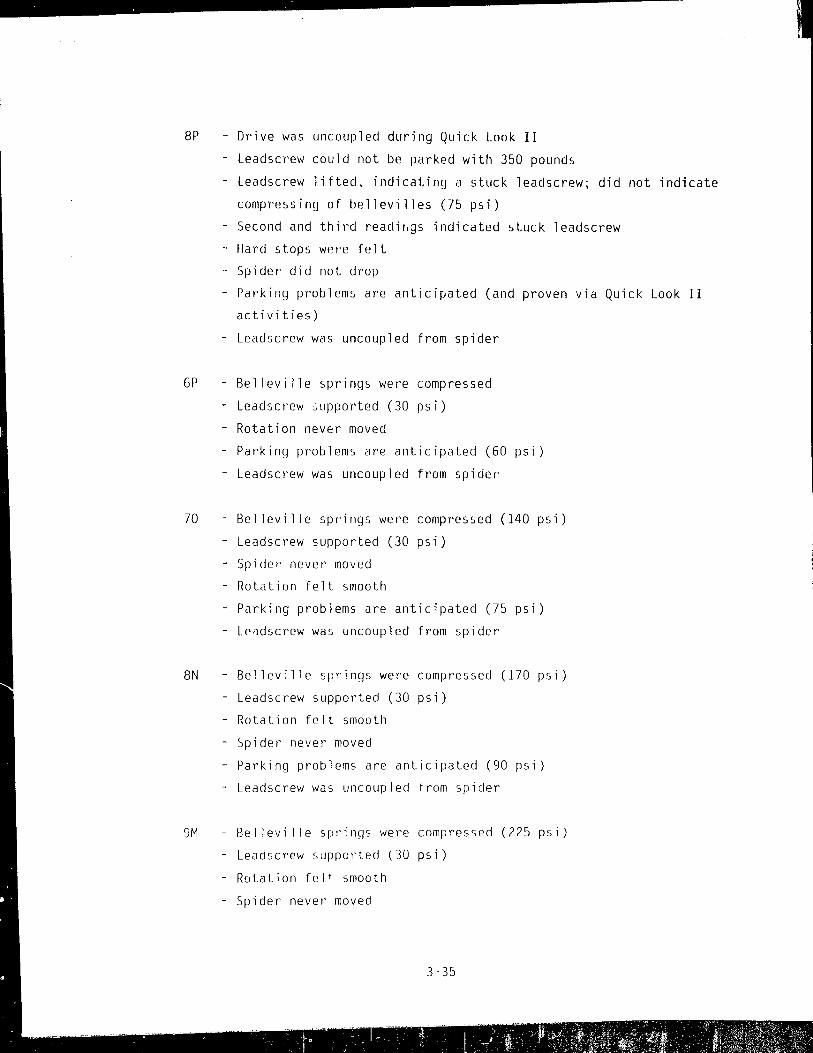
.................. -----------------------
8P - Drive was uncoupled during Quick Look II
- Leadscrew could not be parked with 350 pounds
- Leadscrew lifted, indicating a stuck leadscrew; did not indicate
compressing of bellevilles (75 psi)
- Second and third readi~gs indicated stuck leadscrew
- Hard stops were felt
- Spider did not drop
Parking problems are anticipated (and proven via Quick Look II
activities)
- Leadscrew was uncoupled from spider
6P - Belleville springs were compressed
- Leadscrew ~upported (30 psi)
- Rotation never moved
- Parking problems are anticipated (60 psi)
- Leadscrew was uncoupled from spider
70 Belleville springs were compressed (140 psi)
- Leadscrew supported (30 psi)
- Spider never moved
- Rotation felt smooth
- Parking problems are anticipated (75 psi)
- Le~dscrew was uncoupled from spider
8N - Belleville springs were compressed (170 psi)
- Leadscrew supported (30 psi)
- Rotation felt smooth
- Spider never moved
- Parking problems are anticipated (90 psi)
- Leadscrew was uncoupled from spider
9M - Belleville sprlngs were compressed (225 psi)
- Leadscrew s uppot'ted (30 ps i)
- Rotat ion feP smooth
- Spider never moved
3-35

9M - Parking problems are anticipated (60 psi)
(Cont) - Leadscrew was uncoupled from spider
10L Leadscrew and torque tube moving up and down
- Control rod assembly weight less than ~ormal
- Spider dropped greater than 2 inches
- Parking problems are anticipated
- Leadscrew was uncoupled from spider
11K Leadscrew and torque tube moving up and down
- Control rod assembly weight less than normal
- Spider dropped less than 2 inches after two hard stops were felt
- No parking problems are anticipated (55 psi)
- Leadscrew was uncouoled from spider
12H - Leadscrew and torque tube moving up and down
- Control rod assembly weight less than normal
- Spider dropped greater than 2 inches
- Parking problems are anticipated (60 psi)
- Leadscrew was uncoupled from spider
13G - Leadscrew and torque tube moving up and down
- Control rod assembly weight less than normal
- Spider dropped less than 2 inches
- Parking problems are anticipated (60 psi)
- Leadscrew was uncoupled from spider
14F Belleville springs were compressed (125 psi)
- Leadscrew was supported prior to rotation
- Spider never moved
- Parking problems are anticipated
- Leadscrew was uncoupled from spider
13E - First attempt, the torque tube support ring was stuck to the
torque tube
3--36
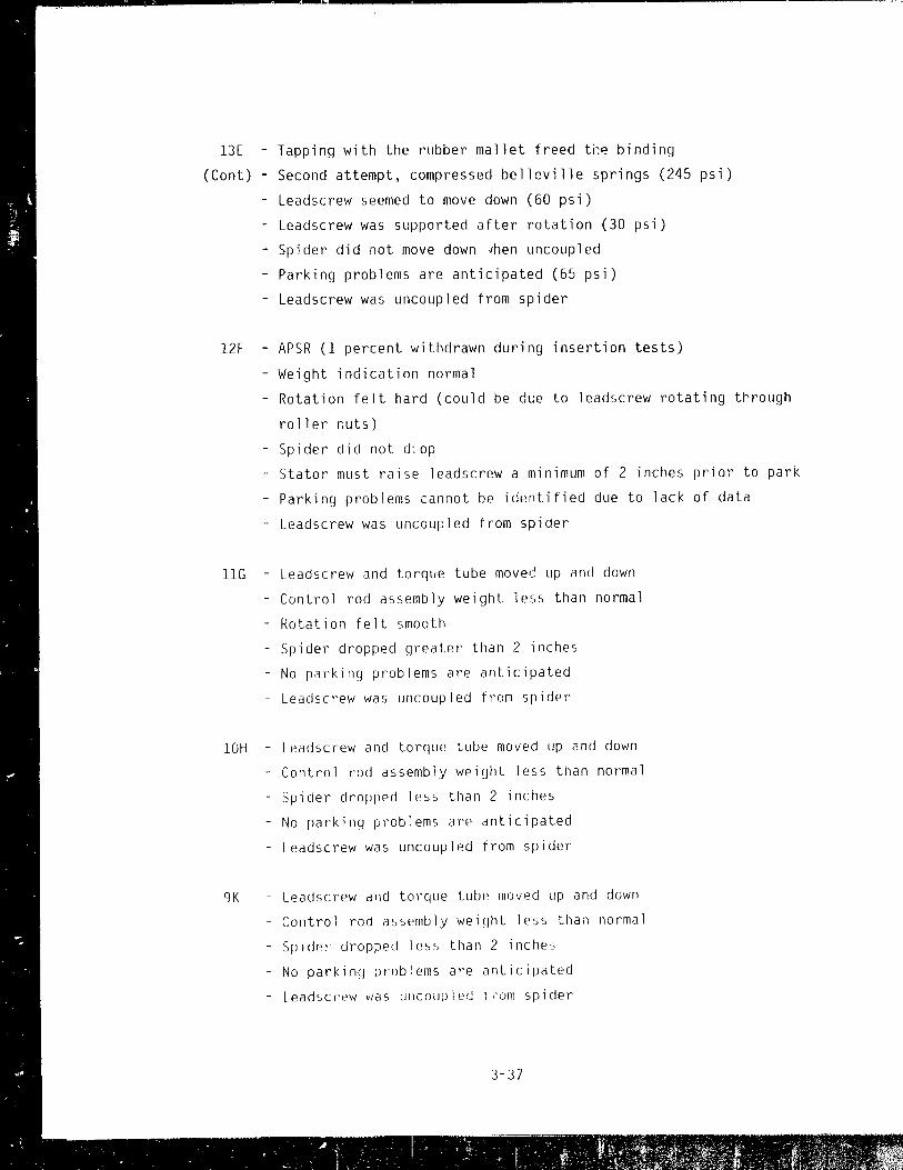
l3E - Tapping with the rubber mallet freed ti~~ binding
(Cont) - Second attempt, compressed belleville springs (245 psi)
- Leadscrew seemed to move down (60 psi)
- Leadscrew was supported after rotation (30 psi)
- Spider did not move down ~hen uncoupled
- Parking problems are anticipated (65 psi)
- Leadscrew was uncoupled from spider
12F - APSR (1 percent withdrawn during insertion tests)
- Weight indication normal
- Rotation felt hard (could be due to leadscrew rotating t~rough
roller routs)
- Spider did not d;op
- Stator must raise leadscrew a minimum of 2 inches prior to park
- Parking problems cannot be identified due to lack of data
- Leadscrew was uncoupled from spider
11G - Leadscrew and torque tube move~ up and down
- Control rod assembly weight less than normal
- Rotation felt smooth
- Spider dropped greater than 2 inches
- No parking problems are anticipated
- Leadscrew was uncoupled from spider
10H - Leadscrew and torque tube moved up and down
- Control rod assembly weight less than normal
- Spider dropped less than 2 inches
- No parkinq problems are anticipated
- Leadscrew was uncouplAd from spider
9K - Leadscrew and torque tube moved up and down
- Control rod assembly weight less than normal
- SpIder dropped less than 2 inches
- No parking prob:ems are anticipated
- Leadscrew vias UllcoLJPlecl lrom spider
3-37
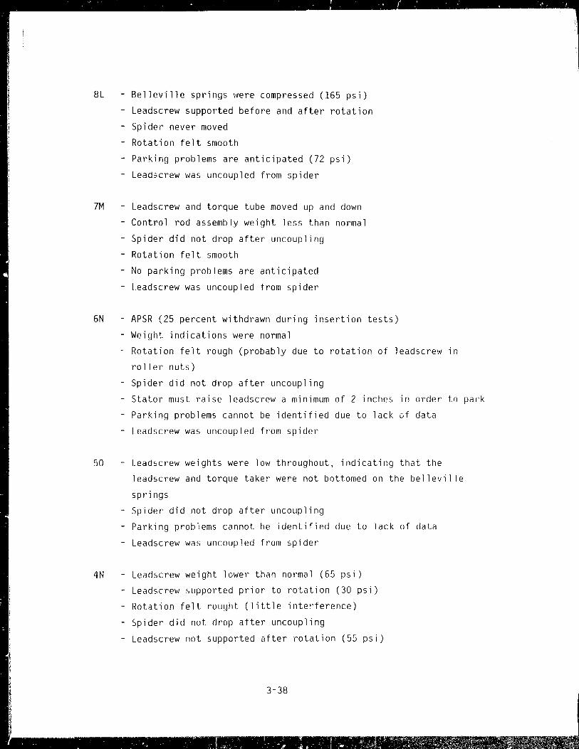
- '- . ,. • 1.' : , ~ . J
8L Belleville springs were compressed (165 psi)
- Leadscrew supported before and after rotation
- Spider never moved
- Rotation felt smooth
- Parking problems are anticipated (72 psi)
- Lead3crew was uncoupled from spider
7}1 - Leadscrew and torque tube moved up and down
- Control rod assembly weight less than normal
- Spider did not drop after uncoupling
- Rotation felt smooth
- No parking problems are anticipated
- Leadscrew was uncoupled from spider
6N - APSR (25 percent withdrawn during insertion tests)
- Weight indications were normal
Rotation felt rough (probably due to rotation of leadscrew in
roller nuts)
- Spider did not drop after uncoupling
- Stator must raise leadscrew a minimum of 2 inches in order to park
- Parking problems cannot be identified due to lack 0f data
- Leadscrew was uncoupled from spider
50 - Leadscrew weights were low throughout, indicatir.g that the
leadscrew and torque taker were not bottomed on the belleville
springs
- Spider did not drop after uncoupling
- Parking problems cannot be identified due to lack of data
- Leadscrew was uncoupled from spider
4N - Leadscrew weight lower than normal (65 psi)
- Leadscrew supported prior to rotation (30 psi)
- Rotation felt rought (little interference)
- Spider did not drop after uncoupling
- Leadscrew not supported after rotation (55 psi)
3-38

4N - Parking problems are anticipated (66 psi)
(Cant) - Leadscrew was uncoupled from spidpr
5M - i.eadscrew weights were low throughout, indicating that the
leadscrew and torque taker were not bottomed on the belleville
springs
- Rotation was rough
- Spider did not drop after uncoupling
- Parking problems cannot be identified due to lack of data
- Leadscrew was uncoupled from spider
6L Belleville springs were compressed
- Leadscrew was supported (35 psi)
- Rotation smooth
- Spider never moved
- Pa:king problems are anticipated (80 psi)
- Le?J~crew was uncoupled from spider
7f' - urlcGup! i fig was attempted duri ng Qui ck Look I
- Second attempt, leadsc~ew weight indication was low, indicating
flU cc~tIU! elements present (verified by Quick Look inspection)
- Approximately 20-degree r~tation
- Parking problems cannot be identified due to lack of data
- Leacisc)'ew VI;:JS not uncoupled from spider
BH - Uncoupled and removed during Quick Look I (see Section 3.2.3)
9G - Leadscrew and torqlle tube moved up and down
- Contl'ol rod weight less than nOI'mal
- Rotation felt smoo:h
- Spieler did not movr~ down after uncoupling
- ParkirlCJ pI'oblems a'oe anticipated
- Leadscrew was uncoupled from spider
lOF - Leadccl'ew and to)'qul? tube moved up and down
3-39
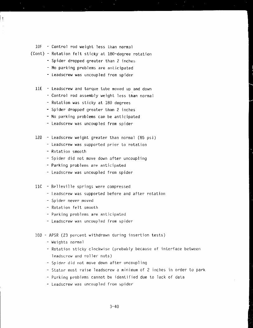
10F - Control rod weight less t.han normal
(Cont) - Rotation felt sticky at 180-degree rotation
- Spider dropped greater than 2 inches
- No parking problems are anticipated
- Leadscrew was uncoupled from spider
11E - Leadscrew and torque tube moved up and down
- Control rod assembly weight less than normal
- Rotation was sticky at 180 degrees
- Spider dropped greater than 2 inches
- No parking problems can be anticipated
- Leadscrew was uncoupled from spider
120 - Leadscrew weight greater than normal (85 psi)
Leadscrew was supported prior to rotation
- Rotation smooth
- Spider did not move down after uncoupling
- Parking problems are anticipated
- Leadscrew was uncoupled from spider
lIe Belleville springs were compressed
- Leadscrew was supported before and after rotation
- Spider never moved
- Rotation felt smooth
- Parking problems are anticipated
- Leadscrew was uncoupled from spider
100 - APSR (23 percent withdrawn during insertion tests)
- Weights normal
- Rotation sticky clockwise (probably because of inte~face between
leadscrew and roller nuts)
- Spider did not move down after uncoupling
- Stator must raise leadscrew a minimum of 2 inches in order to park
- Parking problems cannot be identified due to lack of data
- Leadscrew was uncoupled from spider
3-40

10F - Control rod weight less than normal
(Cont) - Rotation felt sticky at l80-degree rotation
- Spider dropped greater than 2 inches
- No parking problems are anticipated
- Leadscrew was uncoupled from spider
lIE - Leadscrew and torque tube moved up and down
- Control rod assembly weight less than normal
- Rotation was sticky at 180 degrees
- Spider dropped greater than 2 inches
- No parking problems can be anticipated
- Leadscrew was uncoupled from spider
120 - Leadscrew weight greater than normal (85 psi)
Leadscrew was supported prior to rotation
- Rotation smooth
- Spider did not move down after uncoupling
- Parkil,g problems are anticipated
- Leadscrew was uncoupled from spider
lIe Belleville springs were compressed
- Leadscrew was supported before and after rotation
- Spider never moved
- Rotation felt smooth
- Parking problems are anticipated
- Leadscrew was uncoupled from spider
100 - APSR (23 percent withdrawn during insertion tests)
- Weights normal
- Rotation sticky clockwise (probably because of interface between
leadscrew and roller nuts)
- Spider did not move down after uncoupling
- Stator must raise leadscrew a minimum of 2 inches in order to park
- Parking problems cannot be identified due to lack of data
- Leadscrew was uncoupled from spider
3-40
.. - . . - ~--- -- ~ .... -------,~-- i ----. - -- -- --.."...-.----:;-- -"'"'T"""'~ ~-~-~~ ~ \ "-~-~'~. 7r-
- .. ...-,.::; . -

9E - Leadscrew uncoupled and removed during Quick Look II
8F - Leadscrew weights were low through, indicating that the leadscrew
and torque taker were not bottomed on the belleville springs
- Rotation rough and got easier with additional rotations
- Spider did not drop after uncoupling
- Parking problems cannot be identified due to lack of data
- Leadscrew was uncoupled from spider
7G - Leadscrew and torque tube moved up and down
- Control rod assembly weight less than normal
- Rotation was rough, then stopped, then free
- Spider dropped greater than 2 inches
- Parking problems are anticipated
- Leadscrew was uncoupled from spider
6H - Leadscrew and torque tube moved up and down
- Control rod assembly weight less than normal
- Rotation felt smooth
- Spider dropped greater than 2 inches
- No parking problems are anticipated
- Leadscrew was uncoupled from spider
5K - Leadscrew and torque tube moved up and down
- Control rod assembly weight less than normal
- Rotation was rough at 180 degrees
- Spider dropped greater than 2 inches
- No parking problems are anticipated
- Leadscrew was uncoupled from spider
4L - APSR (19 percent withdrawn during insertion tests)
- Weight indications normal
- Spider did not drop after uncoupling
- Stator must raise leadscrew a minimum of 2 inches in order to park
- Parking problems cannot be identified ~Je to lack of data
- Leadscrew was uncoupled from spider
3-41
I , ,
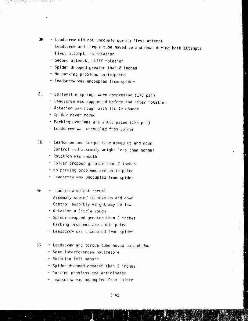
3M - Leadscrew did not uncouple during first attempt
- Leadscrew and torque tube moved up and down during both attempts - First attempt, no rotation
- Second attempt, stiff rotation
- Spider dropped greater than 2 inches
- No parking problems anticipated
- Leadscrew was uncoupled from spider
2L Belleville springs were compressed (170 psi)
- Leadscrew was supported before and after rotation
- Rotation was rough with little change - Spidel' never moved
- Parking problems are anticipated (125 psi)
- Leadscrew was uncoupled from spider
3K - Leadscrew and torque tube moved up and down
- Control rod assembly weight less than normal
- Rotation was smooth
- Spider dropped greater than 2 inches
- No parking problems are anticipated
- Leadscrew was uncoupled from spider
4H - Leadscrew weight normal
- Assembly seemed to move up and down
- Control assembly weight may be low
- Rotation a little rough
- Spider dropped greater than 2 inches
- Parking problems are anticipated
- Leadscrew was uncoupled from spider
5G - Leadsc ,'ew and torque tube moved up and down
Some interferences noticeable
- Rotation felt smooth
- Spider dropped greater than 2 inches
- Parking problems are anticipated
- Leadscrew was uncoupled from spider
3··42

6F - Leadscrew and torque tube moved up and down
- Control rod assembly weight less than normal
- Rotation felt smooth
- Spider dropped greater than 2 inches
- No parking problems are anticipated
- Leadscrew wa~ uncoupled from spider
7E - Leadscrew and torque tube moved up and down
- Control rod assembly weight seemed normal for first reading
- Spider did not drop after uncoupling
- Rotation felt smooth
- No parking problems are anticipated
- Leadscrew was uncoupled from spider
80 - Leadscrew weights were low throughout, indicating that the
leadscrew and torque taker were not bottomed on the belleville
springs
- Rotation felt smooth
- Spider did not drop after uncoupling
- Parking problems cannot be identified due to lack of data
- Leadscrew was uncoupled from spider
9C - Belleville springs were compressed
- Leadscrew was supported before and aft€, rotation
- Rotation felt a little rough
- Spider never moved
- Parking problems are anticipated
- Leadscrew was uncoupled from spider
lOB - Leadscrew weights were low throughout, indicating that the
leadscrew and torque taker were not bottomed on the belleville
springs
- Spider did not drop after uncoupling
- Rotation felt smooth
- Parking problems cannot be identified due to lack of data
- Leadscrew was uncoupled from spider
3-43

88 - Uncoupled and removed during Quick Look II
7C - Leadscrew and torque tube moved up and down
- Some interferences detected
- Rotation felt a little rough
- Spider dropped greater than 2 inches
- No parking problems are anticipated
- Leadscrew was uncoupled from spider
60 - APSR (26 percent withdrawn during insertion tests)
- Weight indications normal
- Rotation a little rough (due to leadscrew roller nut interface)
- Spider did not drop after uncoupling
- Stator must raise the leadscr~w a minimum of 2 inches in order
to park
- Parking problems cannot be identified due to lack of data
- Leadscrew was uncoupled from spider
SE - Leadscrew and torque tube moved up and down
- Control rod assembly weight less than normal
- Spider dropped less than 2 inches after uncoupling
- No parking problems are anticipated
- Leadscrew was uncoupled from spider
4F - APSR (5 percent withdrawn during insertion tests)
- Weight indications normal
~ Spider dropped less than 2 inches after uncoupling
- Stator must raise the leadscrew a minimum of 2 inches prior to park
- Parking problems cannot be identified due to lack of data
- Leadscrew was uncoupled from spider
3G - Leadscrew and torque tube moved up and down
- Control rod assembly weiyht less than normal
- Spider dropped less Lilan 2 inches after two hard str ~ were felt
- No parking problems are anticipated
- Leadscrew was uncoupled from spider
3-44

2H Leadscrew weights were low throughout, indicating that the
leadscrew and torque taker were not bottomed on the belleville
springs
- Rotation felt spongy
- Spider did not drop after uncoupling
- Parking problems cannot be identified due to lack of data
- Leadscrew was uncoupled from spider
2F Leadscrew weights were low throughout, indicating that the
leadscrew and torque taker were not bottomed on the belleville
springs - Excess've amount of torque was applied to the tool and the
leadscrew would not rotate
- Rotation attempts may have increased interferences
- Leadscrew was not uncoupled from the spider
3E Belleville springs were compressed
- Leadscrew supported before and after rotation
- Rotation felt smooth
- Spider never moved
- No parking problems are anticipated
- Leadscrew was uncoupled from spider
4D - Belleville springs were compressed
- Leadscrew supported before and after rotation
- Spider never moved
- Rotation felt smnoth
- No parking problems are anticipated
- Leadscrew was uncoupled from sp~der
5C - Belleville springs were compressed
- Leadscrew supported before and after rotation
- Spider never moved
- Rotation felt smooth
- No parking problems are anticipated
- Leadscrew was uncoupled from spider
3-45

68 - Leadscrew weights were low throughout, indicating that the
leadscrew and torque taker were not bottomed on the belleville
springs
- Rotation felt smooth
- Spider did not drop after uncoupling
- Parking problems cannot be identified due to lack of data
- Leadscrew was uncoupled from spider
3.6 Descriptions of Photographs
Figure 3-17 - This photograph shows the cutting of the leadscrew by band saw.
The band saw is mounted to three CRDM motor tubes and is being operated from
3 feet away.
The leadscrew is wrapped in Herculite for contamination control. In addition, a
chip deflector is mounted over the motor tube so that filings from the cut do
not fall into the motor tube during cutting.
The cut was completed In less than 1 minute.
Figure 3-18 - This photograph shows the operators transporting the wrapped
leadscrew from the CRDM motor tube to a storage pipe at the side of the service
structure. The leadscrew is hanging from an overhead hoist and is being
directed into the storage tube by a long-handled tool to keep distance between
the operator and the leadscrew.
Figure 3-19 - This photograph shows the camera being lowered into the CRDM
motor tube. Work platforms are provided for ease of access around the array of
motor tubes.
Figure 3-20 - This photograph shows either a control rod spring or a fuel rod
spring lying in the core debris bed. More specific identification of the
spring could not be made because the only difference between the two springs is
the length, which could not be determined.
3-46

Figure 3-21 - This photograph shows a portion of the spider found during the
initial inspection at location BH. This portion of the spider is an extreme
close-up of the 'web," i.e.) the connection of two of the spider arms (see Figure 1-6).
Figure 3-22 - This is a photograph of the debris or rubble bed found -5' below
the normal top of the core. Material of this type was found at both the BH and
9E locations.
Figure 3-23 - The right-angle viewing attachment used with the camera during
Quick Look III allowed for inspection of debris deposited on the horizontal
surfaces in the guide tubes at location 9E.
Figure 3-24 - This photograph shows a broken fuel rod among an array of other
wise intact rods.
Figure 3-25 - This photograph shows a burnable poison rod pellet. It is not a
fuel pellet, since fuel pellets are manufactured with dish~d ends.
Figure 3-26 - The top of a spring retainer plug (Figure 3-29) is visible in the
far right center of the picture. Debris is lodged between the ears of an upper
end fitting, above the spring retainer plug, and against the plenum grid pad.
Figure 3-27 - This photograph shows a corner between four end fittings. The
fourth end fitting is barely visible in the lower left center Jf the picture.
Figure 3-2B - This photograph is a view up from the void area at a split tube
in the last (tenth) brazenlent. The tube provides guidance for the inner
control rods and is fabricated from 304 stainless steel.
Figure 3-29 - This photograph shoYis an end fitting spring retainer plug (loca
tion 9E). The debris shown in Figure 3-26 is barely visible. A small gas
bubble is trapped between the spring retainer plug and end fitting car.
3-47

INSTALLED BACK-UP VALVE (SHOWN 90· OUT OF ROTATION FOR CLARITY).
./KNURLED LOCKING ./ SCREW
/VENT CAP
PUSH OOWN TO HARDSTO~ ROTATE CLOCKWISE TO HARDSTOP ENGAGING TOOL STEM WITH THE -VENT VALVE.
- VENT HOUSING
"'-----CLOSURE INSERT ASSEMBLY
CRD VENT VALVE
DISENGAGED POSITION
Figure 3-1. CRDM venting tool.
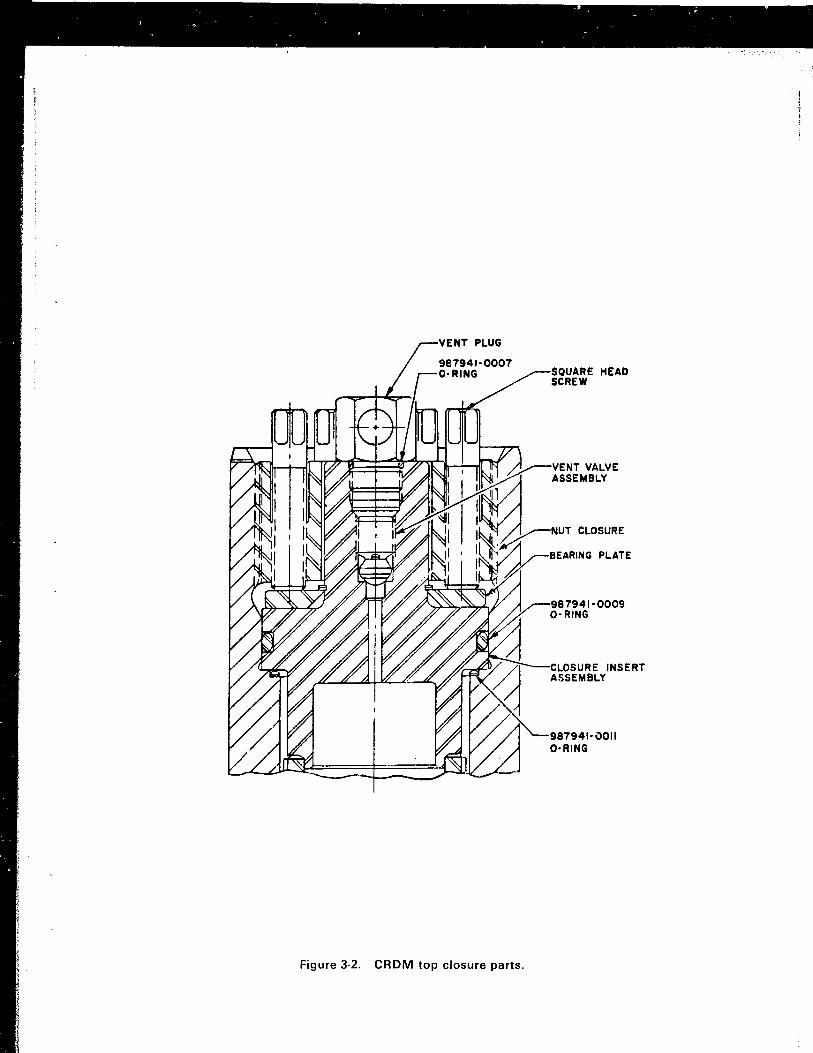
Figure 3-2. CRDM top closure parts.
SQUARE HEAD SCREW
VENT VALVE ASSEMBLY
CLOSURE INSERT ASSEMBLY

Top 7 R/hr
3 R/hr
5 R/hr
Middle 10 R/hr
6 R/hr at 1 foot
2 R;hr
at 1 foot
1 R:hr at 1 foot
Bottom 5 R/hr
Note: Unless noted otherwise, all dose rates are contact dose rates.
Figure 3-:1. Leadscrew 8H dose rates.

Top
Middle
Bottom
1 00 mR/h~
400 mRihr at 1 foot
< 50 R/hr contact
10 R ihr at 1 fool
20 R;hr at 1 foot
20 R/hr
Note: Unless noted :>therwise, all dose rates are contact dose rates.
Figure 3-4. Leadscrew 9E dose ratE";.

Top 2 R/hr
2_3 R/hr
50 R/hr 71 R/hr
11 R Ihr at 1 foot
109 R/hr contact with chip deflector
Middle 72 R/hr
28 R/hr
22 R/hr
3.4 R hr Bottom
Note: Unless noted otherwise, ali dose rates are contact dose rates.
Figure 3-5. Leadscrew 88 dose rates.
4 .. ~ - : • c; .:- ---.- -.
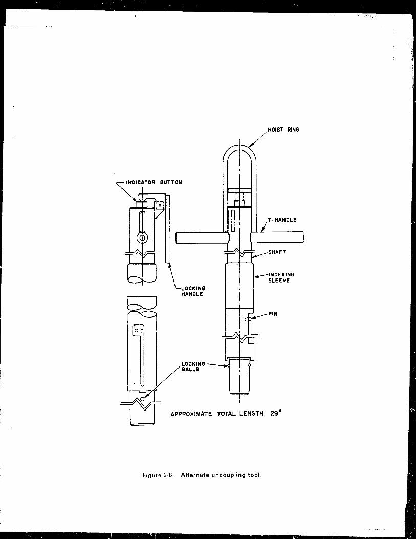
INDICATOR BUTTON
LOCKING HANDLE
HOIST RING
T-HANDLE
SHAFT
INDEXING SLEEVE
PIN
~~~~~~N.
TI APPROXIMATE TOTAL LENGTH 29'
Figure 3-6. Alternate uncoupling tool.

TORQUE TUBE TANG
TORQUE TUBE CAP
r----""_-LOCKING KEY
TORQUE TUBE
KEY
LEADSCRE"W NUT
TOROUE TAKER
....-CYLINDER, HARDSTOP
Figure 3-7. CRDM torque tube assembly.
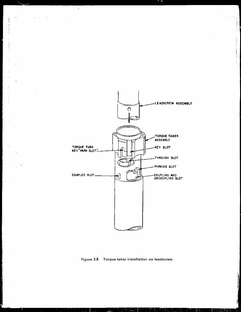
'~ .
TORQUE TUBE
o
LEADSCREW ASSEMBLY
TORQUE TAKER ASSEMBLY
KEY SLOT KEY"PARK SLDT_oo ___ ~::-i.....-t'
~9-::Jii;.:'--I---- THROUGH SLDT
PARKING SLOT
COUPLED SLDT ____ ~ COUPLING AND ~~:::::::;~-",,~y-H---UNCOUPLING SLOT
Figure 3-8. Torque taker installation on leadscrew.
.. • -. ~ ." • t .:. -: ~ - ::' ~ .... -, • _ -, •• J'..... "l-- _".--'~
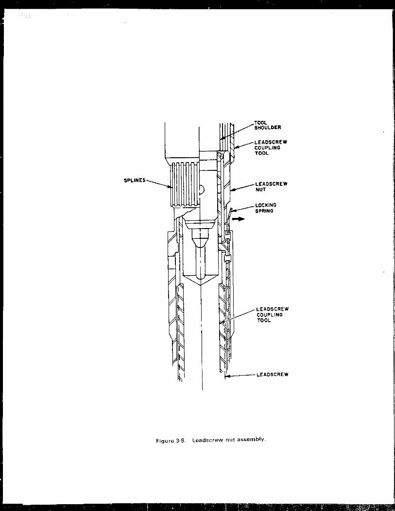
SPLINES
TOOL SHOULDER
LEADSCREW COUPLING TOOL
LEADSCREW NUT
LOCKING SPRING
LEADS CREW COUPLING TOOL
~ ____ --LEADSCREW
Figure 3·9. leadscrew nut assembly.

1 2 3 4 5 6 7 8 9 10 11 12 13 14 15
X
A
E C X C
C x C X
0 A X C
E X C X C X
F C X A X C X C X C X
G X C X C X C X t,; X C X X
H W C x C x C x C x C x C x C Y
K X C X C X C X C X C X C X
L X A X
M C X C
N X C X
0 X C
P P
R
Z
D CONTAINS NO CONTROL COMPONENT
@] CONTROL ROD J~SSEMBUES
0 AXIAL POWER SHAPING ROD ASSEMBLIES
0 BURNABLE POISON ROD ASSEMBLIES
G PRIMARY NEUTiRON SOURCES
LOCATIONS WHERE SPIDERS NEVER MOVED UP OR DOWN
Figure 3-10. Locations where the control rod spiders never moved up or down.

1 2 3 4 5 6 7 8 9 10 11 12 13 14 15
X
A
B C X C X C P
C x C x C x C x C X
0 C X A X C X A X C X
E X C X C X C X C
F C C x C C x C
G X X C X X
H W C x x C x C C Y
K X C X C X C X X
L C X A X C X C C
M C X C X C X ,...
X X \"
N X C X A X C X .A. X C X
0 X C X C X C X C X
P P C x C x C
R
Z
D CONTAINS NO CONTROL COMPONENT
0 CONTROL ROD ASSEMBLIES
0 AXIAL POWER SHAPING ROD ASSEMBLIES
0 BURNABLE POISON ROD ASSEMBLIES
0 PRIMARY NEUTRON SOURCES
LOCATIONS WHERE THE SPIDERS MOVED DOWN LESS THAN 2 INCHES AFTER UNCOUPLING
Figure 3·11. Locations where the spiders mOiled down less than 2 inches after uncoupling.

A
B
C
o
E
F
G
H W
K
L
M
N
o P
R
1 2 3 4 5 6 7 8 9 10 11 12 13 14 15
X
C C P
x C C x x C x x C x
C x C C
C X A X x C x c x C x C C X
f--+--+--+-C x c x c x x X
r-~-+~--+-~-+--~+--+--4--~+--
x C x c C C x C x C X f--+-~~--~+-~~--~~-+~
C X C X A X C
C C x C
x C x x
C
z D CONTAINS NO CONTROL COMPONENT
@] CONTROL ROD ASSEMBLIES
o AXIAL POWER SHAPING ROD ASSEMBLIES
o BURNABLE POISON ROD ASSEMBLIES
o PRIMARY NEUTRON SOURCES
y
LOCATIONS WHEI~E THE SPIDERS MOVED UP WHEN LIFTED, BUT DID NOT MOVE DOWN AFTER UNCOUPLING
Figure 3-12. Locations where tho spiders moved up when lifted, but did not move down after uncoupling.

A
B
C
o E
F
G
H W
K
L
M
N
o P
R
1 2 3 4 5 6 7 8 9 10 11 12 13 14 15
X
CXCXC P ...--+--4---+-
X C C X C X
X C X C X
c X C
C x C
C x x C
~-+-.-
C x X A X C
--+----+-----4-+--+--X C X X C
X XAXCXAXCX
XCXCXCXCX
p CXCXC
z D CONTAINS NO CONTROL COMPONENT
@] CONTROL ROD ASSI:MBLIES
o AXIAL POWER SHAPING ROD ASSEMBLIES
o BURNABLE POISON ROD ASSEMBLIES
o PRIMARY NEUTRONI SOURCES
Y
LOCATIONS WHERE THE SPIDERS DROPPED GREATER THAN 2 INCHES AFTER UNCOUPLING
Figure 3-13. Locations where the spiders dropped greater than 2 inches after uncoupling.

1 2 3 4 5 6 7 a 9 10 11 12 13 14 15
X
A
B
C
o
C x x C x C
x C X A X
E C X x C x C x F C X
G X C
H W C X I---+-----+---
K X C -+---+---'
L X A
M C N X
o P
R
P
CONTAINS NO CONTROL COMPONENT
CONTROL ROD ASSEMBLIES
AXIAL POWER SHAPII'~G ROD ASSEMBLIES
BURNABLE POISON ROD ASSEMBLIES
PRIMARY NEUTRON SOURCES
z
Y
x
LOCATIONS WHERE THE LEADSCREWS HAVE BEEN UNCOUPLED, BUT PARKING MAY BE DIFFICULT
Figure 3-14. Locations where the leadscrews have been uncoupled, but parking the lead screws may be difficult.

1 2 3 4 5 6 7 8 9 10 11 12 13 14 15 X
A
B • x X • C P
C x C x C x C x C x
D x c X A X X A X C X
E C X C X C X C X C X C
F C X A X C X X C X A X C
G
H W
X G X C X C X C X C X C X :.)( C X C X C X C X C X C Y
K X C X C X C X C X C X C X
L C )( A X C X C X C X A X C
M G X X C X C X C X C
N )( C X A X C X A X C X
0 X X C X C X C X
P P C x C x C
R
z D CONTAINS NO CONTROL COMPONENT
[£] CONTROL ROD ASSEMBLIES
o AXIAL PO'WER SHAPING ROD ASSEMBLIES
o BURNABl.E POISON ROD ASSEMBLIES
o PRIMARY NEUTRON SOURCES
LOCATIONS WHERE THE LEADSCREWS AND TORQUE TAKERS ARE NOT BOTTOMED ON THE TORQUE TUBE BELLEVILLE SPRINGS
Figure 3-15. Locations where the leadscrews and torque takers are not bottomed on the torque tube belleville springs.
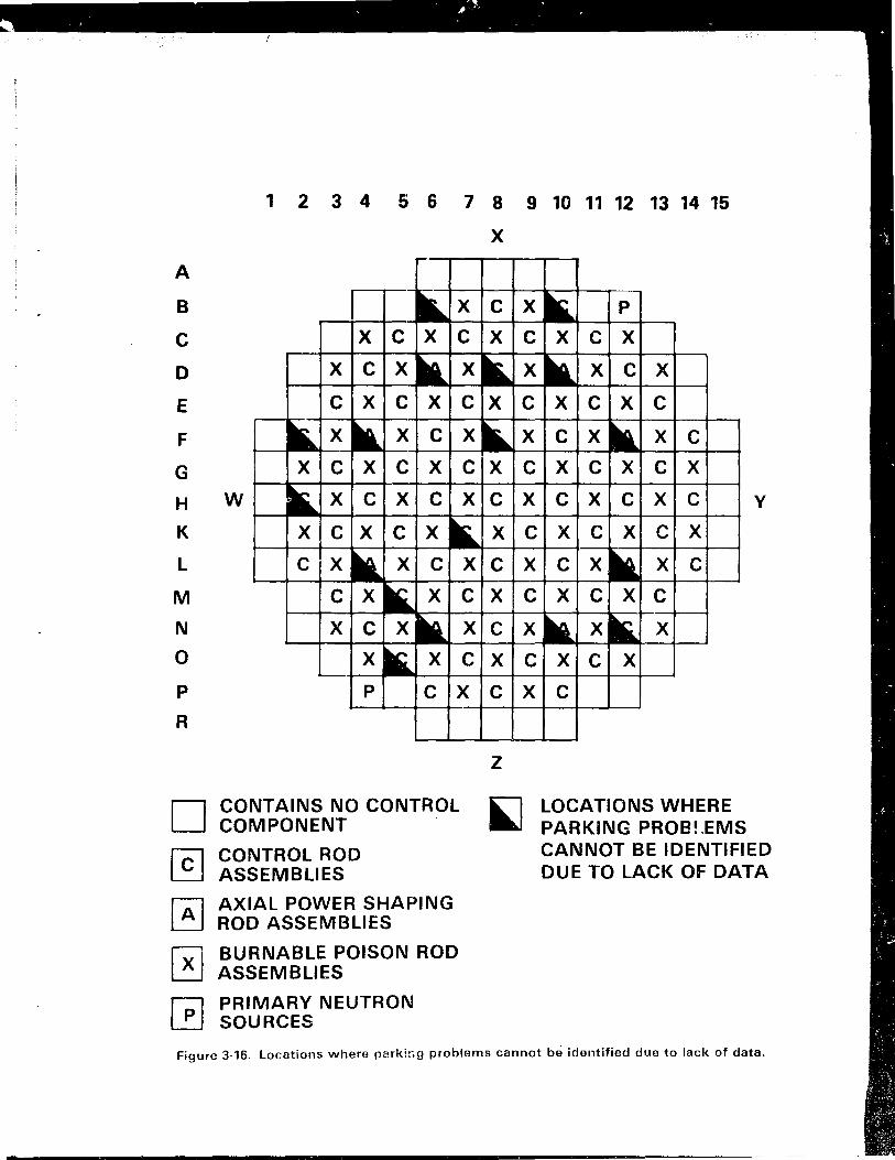
A
B
C
D
E
F
G
1 2 3 4 5 6 7 8 9 10 11 12 13 14 15
X
P
x C c x x C x C x C x c x C
x x c -....---+----+-
x C x C x H W x C x C x C Y
K
L
M
N
o P
R
x C C x c x c x C x x x C
~~~--+-4--+-4~
C X C C
x C x X -t--+-----+-
X C X C X
x C x C
CONTAINS NO CONTROL COMPONENT
CONTROL ROD ASSEMBLIES
AXIAL POWER SHAPING ROD ASSEMBLIES
BURNABLE POISON ROD ASSEMBLIES
PRIMARY NEUTRON SOURCES
z
LOCATIONS WHERE PARKING PROBLEMS CANNOT BE IDENTIFIED DUE TO LACK OF DATA
Figure 3-16. Locations where parkir,g problems cannot be identified due to lack of data.


Figure 3-18. Removing the wrapped leadscrew from tne service structure to a storage tube Bit the sljd" ~~ the <:I'!fvice structure.

. . . .. . " , " ' .• . .' ~" .' .', it,c ~"", " . .' "
. . . ~, ~ , .. ~ ..

. \..-. \
, .
en .;:: .c ell • 'tJOl
~ .§ ... Q. C en 0'tJ Ole .= Qj ~:J .r:. .... ... .... OlO C'tJ .! 0 ... 'tJ_ ell 0 C ... . - ~ E C ... 0 ell U ~ m 'tJ en C .-::l .!!!
.... .r:. 0'" Ol' C';: ';:: Ol Q.C (J)~
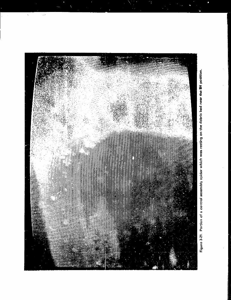
. ~ " " " o ~ , .: 0
. . . . . ., . .
•


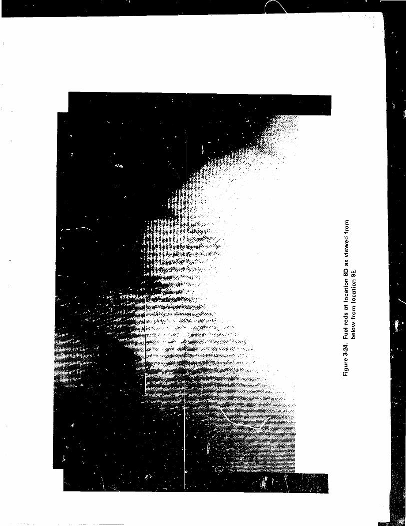
E o ... ....
"0 Q)
:: (j)
'> U) (II
Ow 000) c: c: o 0 .~ 0;:i (II (II u u o 0
rti E U) e
"0 ....
e :: 'Q).2 ::J Q) u.,Q

VI .~
.c Q)
'0 Q)
.£: ...

\ • - ,- •• -<' 1-t.-' .' , I· _ . ~ " ~ -
Co ::l
,!!l ::: ~
~ o ';:; 'iii o Co w en Q)
.s::. ... ~
Cl ~ of ~
... Q)
Co Co ::l
~
'tI Q)
Cl 'tI .!2 If)
'': .c Q)
C
~ M Q) ... ::l Cl u:


;: Q) ... Q)
E ,!!! 'Ll
c: ..c: (J c:
> Qj ... III
E 'j( o ... c. C. III
Cl ~
C. ... Q)
c: III ... Q) ... Cl c: 'i: C.
C/)
gj M I\) ... ~ Cl u:

4. SUMMARY
4.1 Quick Look Objectives and Sch~dule
The Quick Look was designed to provide the first vlsual information on the condition of the core and upper irternals by inspecting the control rod guide
tubes, a portion of the upper grid, the tops of fuel assemblies, and, in the
event that the upper end-fittings were missing, the reactor core. This infor
mation was to be obtained by inserting a radiation-tolerant underwater CCTV
camera through an opening created by the removal of a leadscrew from a CROM.
The initial inspection was conducted on July 21, 1982, as originally scheduled.
Additional inspections were conducted on August 5 and 12, 1982.
As a follow-up to the core inspections, leadscrew uncoupling was completed
on August 23 and 25, 1982.
4.2 Methods and Approach
Preparations had to be made in the following areas:
o Supporting studies and licensing documents development
o Uncoupling and removal tool design and methods planning
o Plant modifications and additions
o Operator training
o Procedure preparation
o Radiological predictions and ALARA provisions
For the most part, these activities took place concurrently.
4-1

• {. fl'~
"'... - . .. ..... . .
4.2.1 ~upporting Studies and Licensing Documents
Several studies were performed whose results were applicable to the safety
concerns of this activity. The B&W report, "Methods and Procedures of Analysis
for TMI-2 Criticality Calculations to Support Recovery Activities Through Head
Removal ," was prepared to document criticality safety results from the analyses
of vari~us geometrical configurations of moderator, reflector, and fuel. The
assessment demonstrated that, during all of the proposed activities that could
produce fuel rearrangements or otherwise affect the subcriticality of the fuel
system, the TMI-2 reactor would be maintained in a safe shutdown condition.
The thermal status of the core and predictions of the thermal response of
the system to partial draindown of the RCS were discussed in the B&W report,
"TMI-2 Decay Heat Removal Analysis." The rE:sults of the analysis showed that
lowering the reactor water level and isolating the system components might
cause an increase in reactor water equilibrium temperature at a rate of less
than 5 F per day in mid-1982. This increase was dependent upon the containment
air temperature. If enhanced heat removal was required, it could be accomp
lished by existing systems.
An analysis was performed to determine the quantities of hydrogen and
Kr-85 in the RCS available for release to the containment and the environment.
The total amount of Kr-85 available for release was conservatively calculated
to be approximately 30 Ci, which would result in an increased dose rate at the
nearest residence of 2.1 x 10 5 mrem (total body dose). It was concluded that
all radioactive releases from the containment as a result of the Quick Look
would be well within the limits of the TMI-2 Technical Specifications. The gas
vented from the RCS was assumed to be 100 percent hydrogen. To prevent the
discharge of a flammable hydrogen mixture to the containment atmosphere, the
RCS was vented into a dilution air stream.
The rate of hydrogen offgassing via the open CROM motor tube was conser
vatively calculated at approximately 0.03 scfm. Although appropriate precau
tions were taken, it was determined that such a low release rate would not have
4-2
I i
I I I ;i

presented a hydrogen flammability hazard when vented directly to the contain
ment.
The results of analyses identifipd above were used in the "Safety Evalu
ation for Insertion of a Camera into the Reactor Vessel Through a Leadscrew
Opening" (Quick Look Safety Evaluation), which was the primary licensing
document for this activity. The report also evaluated the potential for
inadvertent boron dilution, occupational exposure, and the effects on RCS
chemistry as a result of breaching the RCPS. The conclusions of this report,
which were accepted by the NRC, were that the activities associated with the
Quick Look would not present an unreviewed 'Cdfety issue, nor would they present
undue risk to the health and safety of the public.
4.2.2 Leadscrew Uncoupling Plan and Tool Development
The basic approach was to uncouple a central leadscrew using one of two
normal uncoupling techniques: the leadscrew nut method, or if that was unsuc
cessful, the torque tube method. After successful uncoupling, the leadscrew
was to be lifted into the parked position. Once the cuttir:g tools were staged,
the 1eadscrew would be cut to remove it, since it was too long to be completely
withdrawn under the missile shields.
To perform leadscrew uncoupling, removal, and subsequent camera inspection
with the missile shields in place, existing tools had to be modified and new
tools developed. Criteria reflecting such concerns as ALARA, space and mate
rial constraints, and manual transportation of tools were established foy' the
development effort. To ensure safe and proper operation, proof-of-principle
testing was performed on all new or modified tools.
4.2.3 Plant Modifications and Additions
Modifications or additions were made to existing systems for venting and
draining, w3ter level monitoring, leadscrew rigging and handling, and com
munications. Only those modifications or additions necessary for the Quick

- . • tr,;>r • • ~ I
.. 4
.. .,. .
Look were made, so as to minimize the man-rem and man-hours expended on this task.
4.2.4 Operator Training and Procedure Preparation
Operators were trained in the use of the CRDM tools and in the operation
of the special video camera. This training included all aspects of the equip
ment, activities to be performed with the equipment, and the interfacing
systems. In addition to this equipment-specific training, dress rehearsals
were performed on a full-scale mock-up of the service structure. The mock-up
included a CRDM, the missile shields, and the hoisting mechanism.
Sixteen new operating and emergency procedures were generated and six
procedures were modified for the Quick Look. Subsequent to Quick Look I, five
Temporary Change Notices to procedures were required, and two special operating procedures were written.
4.2.5 Radiological Predictions and ALARA Considerations
Approximately 50 to 150 man-rem were estimated for the Quick Look. These
figures were arrived at by estimating the in-containment man-hours that w0uld
be required for the task and assuming general area dose rates. It was also
necessary to determine the dose rate from the leadscrew so that adequate
shielding for th2 leadscrew could be provided once it was removed to prevent unneccessary personnel exposure.
ALARA prOV1Slons were implemented in procedures anc tool design. These
provisions included long-handled tools, mock-up testing, contingency procedures,
increasing equipment maneuverability, and time-saving devices.
Detailed radiological control measures were included in the work packages
rather than the procedures. Appropriate stay ~llIIes or special instructions
4-4
:1 .1

were written into the work package based on anticipated radiological condi
tions. This was done to permit flexibility in allowing work to continue if significant changes in radiation levels were encountered.
During leadscrew removal and cutting the radiological controls technician
monitored the beta and gamma dose rates. Radiation detectors were also located
on the service structure to continuously monitor radiation levels.
Protection from beta radiation was proviced by the use of shielding and
clothing requirements, as necessary. Additional protection from beta radiation
was provided by the ice vests used for body cooling, lineman's gloves, and eye protection.
4.3 Execution
4.3.1 Containment Entries and Data Collection
A total of 27 containment entries and 243 in-containment man-hours were
required to prepare for and perform the Quick Look. The accomplishments of
these entries included primary and secondary side venting and draining, gas and
liquid ~~mple collection, leadscrew removal, performance of the Quick Look
camera inspections, and leadscrew uncoupling.
During entry 73, two gas samples (one line purge sample and one system
sample) and one liquid sample were obta~ned zrom the CRDM. Contact RO-2A
readings on the gas samples were 150 mR/hou~ gamma from both, and 400 mrad/hour
beta from the line purge and 520 mrad/hour beta from the system vent. The
contact reading o~ the liquid sample was 150 mR/hour gamma and 400 mrad/hour beta.
One RCS liquid sample was obtained during entry 75. The sample was
obtained by lowering a 150 ml sample bomb into the ,eactor vessel through the
4-5

CRDM to a depth 28 feet below the top of the motor tube. Contact RO-2A read
ings on the RCS liquid sample bomb were 100 mR/hour gamma and 240 mrad/hour beta.
When the leadscrew was removed no warpage or other deformity was noted.
The highest radiation reading from the leadscrew was 6.0 R/hour gamma at a
distance of 1 foot from the second half of the leadscrew.
4.3.2 Leadscrew Uncoupling Descriptions for Drive Locations 7K and 8H
During the first attempt to uncouple the leadscrew 0n CRC~ BH, there were
indications of interference or damage because the ir~tial load reading of 350
pounds exceeded the anticipated load reading. Although the leadscrew nut
rotated freely, the leadscrew would not lower or rotate. Finally, the lead
screw was tapped down far enough to allow rotation through approximately 45
degrees. The leadscrew still could not be lifted without exceeding the adminis
trative load limit of 350 pounds. In the continuing attempts to uncouple the
leadscrew it was rotated beyond the 45-degree point, which, according to later
analysis, indicated that the spider had probably fallen off.
Since no apparent progress was being made, the uncoupling of the leadscrew
at CRDM 7K was attempted; however, these attempts were also unsuccessful and
efforts were resumed on the leadscrew at CRDM BH. The leadscrew nut was
rotated clockwise in order to return the drive to its original position. When
the nut rotated 20 times instead of the expected 4 to 7 times, it was taken as
an indicat;0r. that the leadscrew was in fact uncoupled and the nut was bottomed
on the ieadscrew engagement pins.
The leadscrew WOUld still not move when loaded to the administrative limit
of 350 pounds, so the operator was instructed to jar the tonl in an attempt to
determine the location of the hang-up. At this point the leadscrew broke free
and th~ load reading was 170 pounds as expected. The removal process then
continued as planned.
4-6

4.3.3 Observations from the Camera Inspections
The Quick Look camera inspections were performed inside the TMI-2 reactor
vessel on July 21, August 6, and August 12, 1982. The camera revealed that
the upper central portion of the reactor fuel has collapsed and forms a loose
bed of rubble, whose upper surface is about 5 feet below the normal top of the core.
The Quick Look Tape Review Group report, Data Report - Quick Look Inspec
tion Results (TOP/TMI-026), December 1982, GPU Nuclear Planning Department,
documents the review group's observations from their review of the videotapes of the camera inspections.
4.3.4 Core Probe Experiment
The core probe experiment was conducted concurrently with the Quick
Look III camera inspection. The core probe was inserted into the 8H and 9E
positions. At both positions, the probe was inserted about 14 inches into the rubble bed.
4.3.5 Leadscrew Uncoupling Activities
The uncoupling of each leadscrew is described in Section 3.5. Based on
analysis of the data obtained during uncoupling, the leadscrews can be grouped
into the following categories, which are not mutually exclusive:
1. Locations where the control rod spiders never moved up or down.
2. Locations where the spiders moved down less than 2 inches after uncoupling.
3. Locations where the spiders moved up when lifted but did not move down after uncoupling.
4-7

4. Locations where the spiders dropped greater than 2 inches after uncoup 1 i ng.
5. Locations where the leadscrew has been uncoupled but leadscrew parking may be difficult.
6. Locations where the leadscrew and torque taker are not bottomed on the torque taker belleville springs.
7. Locations where lack of leadscrew movement will not allow a potentially stuck leadscrew to be identified.
4-8

5. REFERENCES
1. J. R. Worsham III et al., Methods and Procedures of Analysis for
TMI-2 Criticality Calculations to Support Recovery Activities Through
Head Removal, BAW-1738, June 1982. (This report is Appendix A of Reference 3.)
2. TMI-2 Decay Heat Removal Analysis, April 1982. (This report is
Appendix B of Reference 3.)
3. Safety Evaluation for Insertion of a Camera into the Reactor Vessel
Through a Leadscrew Opening, Revision 2, July 1982. (This report
was submitted to the U.S. Nuclear Regulatory Commission by GPU
Nuclear letter 4400-82-L-0110, July 6, 1982.)
5-1

APPENDIX A
DESIGN FUNCTIONAL CRITERIA AND DRAWINGS FOR NEW AND MODIFIED TOOLS
-. ~ J ;:. ,- _ - ~ ,,, • '_ _
j ! 1 , , ! I
! : , '
i ; ,
1 ' ,

DESIGN FUNCTIONAL CRITERIA
MODIFIED LIGHTWEIGHT LEADSCREW LIFTING TOOL
1. Pick up leadscrew by engaging leadscrew nut.
2. Rotate leadscrew while lifting in order to uncouple from spider and torque taker.
3. Pull test to minimum of twice leadscrew weight, 350 pounds minimum.
4. Work within geometric constraints of CRDM, i. e., fit in torque tube.
5. Designed to be hand carried to the service structUl'e.
6, Material compatible with RCS.
7. Work in conjunction with leadscrew nut runner tool, i, e., fit through the nut runner and the leadscrew jacking device simultaneously,
8. All potential loose parts captured.
9. Equipment shall be designed to facilitate installation and operation by personnel performing under the constraints imposed by protective clothing.
10. Maximize use of design features of the existing DPSC lightweight leadscrew lifting tool.
11. No painted parts.
12. Smooth surfaces wherever practical for ease of decontamination.
13. Burr-free with no sharp edges.
14. Ball lock mechanism does not release upon loss of air.
15. Capable of engaging a leadscrew in the full up or down position with nut runner installed.
16. Compatible with C-washers.
17. Designed to lift and hold the leadscrew during nut unthreading operations.
18. Tool design shall address ALARA.
A-2
Specific design functional criteria were established for each new or modified tool. These criteria and drawings for these tools are included in this appendix.
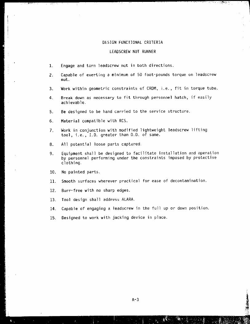
DESIGN FUNCTIONAL CRITERIA
LEADSCREW NUT RUNNER
1. Engage and turn leadscrew nut in both directions.
2. Capable of exerting a minimum of 50 foot-pounds torque on leadscrew nut.
3. Work within geometric constraints of CRDM, i.e., fit in torque tube.
4. Break down as necessary to fit through personnel hatch, if easily achievable.
5. Be designed to be hand carried to the service structure.
6. Material compatible with RCS.
7. Work in conjunction with modified lightweight leadscrew lifting tool, i.e., 1.0. greater than 0.0. of same.
8. All potential loose parts captured.
9. Equipment shall be designed to facilitate installation and operation by personnel performing under the constraints imposed by protective clothing.
10. No painted parts.
11. Smooth surfaces wherever practical for ease of decontamination.
12. Burr-free with no sharp edges.
13. Tool design shall address ALARA.
14. Capable of engaging a leadscrew in the full up or down position.
15. Designed to work with jacking device in place.
A-3
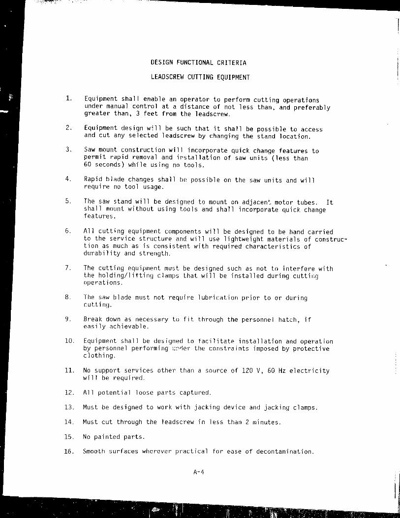
DESIGN FUNCTIONAL CRITERIA
LEADSCREW CUTTING EQUIPMENT
1. Equipment shall enable an operator to perform cutting operations under manual control at a distance of not less than, and preferably greater than, 3 feet from the leadscrew.
2. Equipment design will be such that it shall be possible to access and cut any selected leadscrew by changing the stand location.
3. Saw mount construction will incorporate quick change features to permit rapid removal and irstallation of saw units (less than 60 seconds) while using no tools.
4. Rapid blade changes shall be possible on the saw units and will require no tool usage.
5. The saw stand will be designed to mount on adjacen~ motor tubes. It shall mount without using tools and shall incorporate quick change features.
6. All cutting equipment components will be designed to be hand carried to the service structure and will use lightweight materials of construction as much as is consistent with required characteristics of durability and strength.
7. The cutting equipment must be designed such as not to interfere with the holding/lifting clamps that will be installed during cuttil~g operations.
8. The saw bla~e must not require lubrication prior to or during cutting.
9. Break down as necessary to fit through the personnel hatch, if easily achievable.
10. Equipment shall be designed to facilitate installation and operation by personnel performing ~~~er the constraints imposed by protective clothing.
11. No support services other than a source of 120 V, 60 Hz electricity will be required.
12. All potential loose parts captured.
13. Must be designed to work with jacking device and jacking clamps.
14. Must cut through the leadscrew in less than 2 minutes.
15. No painted parts.
16. Smooth surfaces wherever practical for ease of decontamination.
A-4

LEADSCREW CUTT.ING EQUI PMENT (Continued)
17. Burr~free with no sharp edges.
18. Tool design shall address ALARA.
A-5

DESIGN FUNCTiONAL CRITERIA
LEADSCREW LIFTING CLAMP
1. Must be capable of being installed from at least 3 feet away,
2. Ability to ue installed with saw and stand in operating position.
3. Contain integral lifting bail with 500 pounds minimum load carrying capabi 1 ity.
4. Clamp bo~h threaded or unthreaded portions of leadscrew.
5. Material compatible with Res.
6. All potential loose parts captured.
7. Clamping force sufficient to provide lifting capability of 500 pounds minimum.
8. Equipment shall be designed to facilitate installation and operation by personnel performing under the constraints imposed by protective clothing.
9. Must fit within 5-inch 1.0. pipe after installation on leadscrew.
10. Remote clamping capabilities (at least 3 feet away) must be developed as contingency.
11. No painted parts.
12. Smooth surfaces wherever practical for ease of decontamination.
13. Burr-free with no sharp edges.
14. Clamps shall prevent leadscrew from falling inside motor tube.
15. Tool des;'n shall address AlARA.
A-6
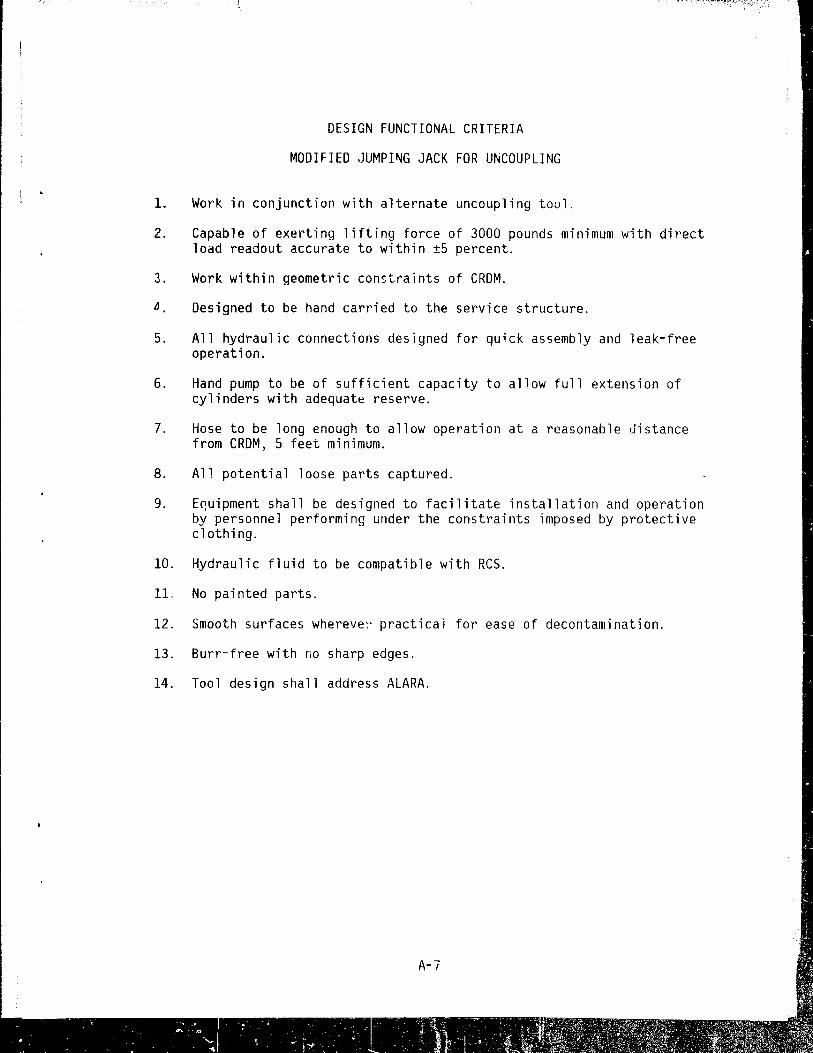
DESIGN FUNCTIONAL CRITERIA
MODIFIED JUMPI~G JACK FOR UNCOUPLING
1. Work in conjunction with alternate uncoupling tool.
2. Capable of exerting lifting force of 3000 pounds minimum with direct load readout accurate to within I5 percent.
3. Work within geometric constraints of CRDM.
~ Designed to be hand carried to the service structure.
5. All hydraulic connections designed for quick assembly and leak-free operation.
6. Hand pump to be of sufficient capacity to allow full extension of cylinders with adequate reserve.
7. Hose to be long enough to allow operation at a reasonable distance from CRDM, 5 feet minimum.
8. All potential loose parts captured.
9. E~uipment shall be designed to facilitate installation and operation by personnel performing under the constraints imposed by protective clothing.
10. Hydraulic fluid to be compatible with ReS.
11~ No painted parts.
12. Smooth surfaces wherelfe:' practical fot' ease of decontamination.
13. Burr-free with no sharp edges.
14. Tool design shall address ALARA.

DESIGN FUNCTIONAL CRITERIA
QUICK LOOK CHIP DEFLECTOR
1. Shall be designed for rapid installation around the leadscrew to permit installation while the leadscrew is suspended by a hoist.
2. The interface between thp ~hip deflector and the leadscrew will be designed to accommodate the variations present in leadscrew geometry during its withdrawal from the motor tube.
3. All chip deflector parts are to be captured or fastened to prevent entry into the motor tube.
4. Design shall consider the constraints imposed by protective clothing and will allow installation and removal without the use of tools.
5. Shall be constructed of lightweight materials for ease of transport.
6. Tool design shall address ALARA.
7. Smooth surfaces wherever possible for ease of decontamination.
8. Burr-free with no sharp edges.
9. No pai nted parts.
10. Mat.erial compatible with the Res.
A-8
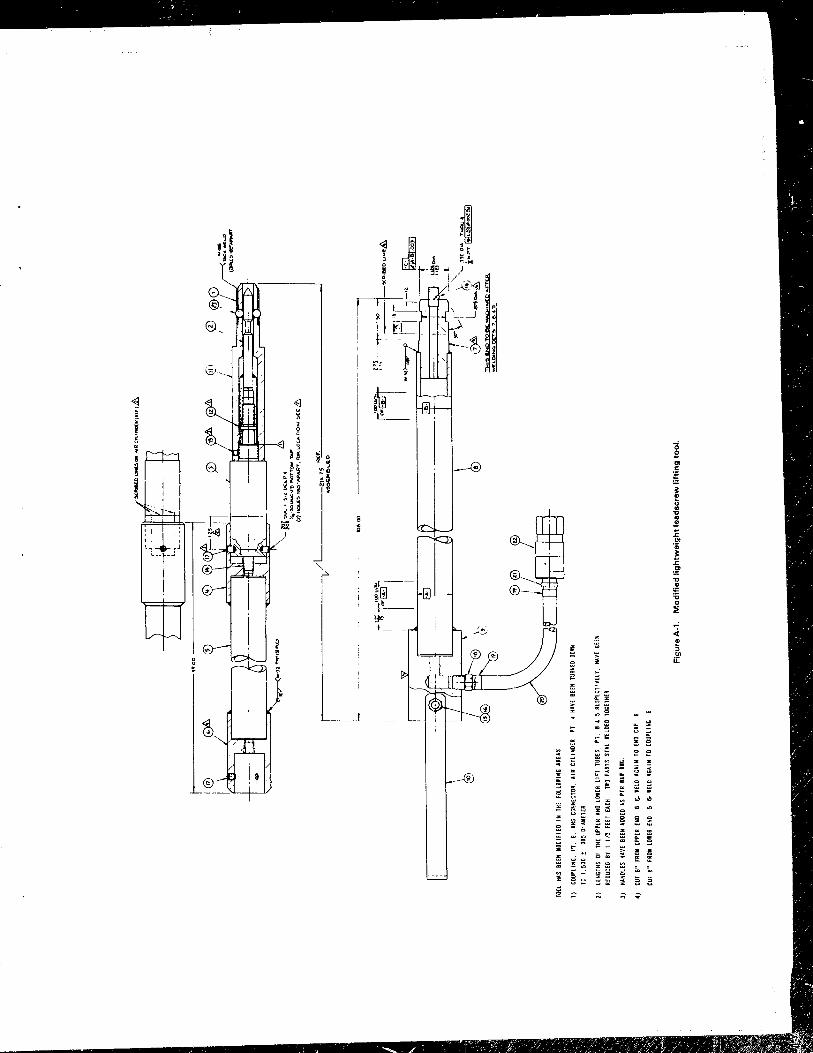
~ :;: u 0 z
z ~
m
I u
~ , --® ~
@ ~ . ~ <ol
~
u c z
c t .;
.: x ~ . :>
z x u ~
0 ~ u
~ ;:; ;:; ~

- - \ . ~ ~ ---. -: -: - --~- - . ------r-~~ -- .---• #. '.

~ 'l!~
-~~
:r ",.-.
,~ =i'i= , ;0:
r+ /L'-" .u;r @
. ... ~
... I:
'" E a. ':; C'
'" '" I:
'f " " J ~
" "' ."
" ~ Pi ci: '" ;; '" u:

,;;
---fJlfl------
/.E/1DSC~EW Ct./iMP I C/.05UFfe ///f.If67-lJ
I ,")--,.
"61 6
LEIiDSC/ll'W CLIIMP e CLOSURe R/II/GT-R
Figure A-4. Lead.crew lifting clamp_

- Iq 5-18- / 8 HE){ ~ C.qP5(R':W
B 1l£~'D --
MOTOR TlJI(HRE F.
--v-~'1.1. p./.rUllE,REF.
I
('----+------1 - -2 UPPER PL"Tf :'SS,
~ -3 6AU6£
--4 .OWER rLiHE ASS'(
- -8 FITT/N&
-- - 10 TUe,~, 2. I>,EQ 0
Figure A-5. Modified jumping jack for uncoupling.

! f r--I \
/ /
- -- ---, (lV-t. ... \....."O.>\ (. ... ,~ t:;~~C\()'.
WJ\\~ R",,,- (~ I~
~"'.~,..-~.'i'Eo
Wrt'" 1.t) 10 MfIo,\C." 0.0..
O<~"
'o."..~ l<:::P~ (.\loV' OCh,£C\:OU.. '"s.E~\K: v.~\.\l"\ t~ 30)
Figuna A·6. Quick Look chip deftector.
o.\~ r.l-----~~4 J o'\~:::l..-~C:::=======:::::JI::2l t ---r==-- ea
'QXf.~ c..K\i> Cef"l..Q.,oa. f.::ot C\.Jl..VIp (P"'«'T Z\
...-c.tJT"O~"~ ~""O't~ ~9am\""'(.n. ~"' ..... ~
PART 4 0,75 • FROST KIt~G- fEl T
Wf,. THER 5TRJP T ..... PE. '((J;"P"~D T ... /::r
PARl S 0.75 • n~os'" WING" fOAM
wt.ATIi[R !oTRI~ TAPE, WIi.I,~F:O"TV""J':[
- -j --