056-2004 sid manuscript
TRANSCRIPT

12.1 / A. Kurtz
12.1 : Digital Cinema Projection with R-LCOS DisplaysAndrew F. Kurtz, Barry D. Silverstein, and Joshua M. Cobb
Eastman Kodak Company, Rochester, New York, USA
AbstractA digital cinema projector developed by Eastman Kodak Company, utilizing three JVC QXGA LCDs, and providing 12,000 lumens, 2,000:1 contrast, and 3 Mpixel resolution, is described. This system, which has a novel optical configuration, wire grid polarizers and polarization compensators, provides high contrast at low F#, a large color gamut, and minimal stress birefringence at high power.
1. IntroductionThe future of electronic cinema was dramatically foreshadowed in 1999, when the film “Star Wars: Episode I – The Phantom Menace” (Lucas Films) was exhibited in Los Angeles and New York, with two JVC ILA projectors and two Texas Instruments DLP projectors exhibited in parallel [1,2]. The DLP platform has since progressed, from a 0.9" chip with 1 MP resolution and ~800:1 system contrast at F/3, to a 1.25" diagonal chip with 2 MP resolution and ~1800:1 contrast at F/2.4. The JVC ILA projector provided ~17,000 screen lumens and 1500:1 contrast with F/4.6 optics. However, the ILA projector was assembled with at least two technologies (2.5" diagonal CRT back written ILA panels and liquid immersed polarization prisms) which are now considered obsolete. JVC has continued projector development activities around their D-ILA reflective liquid-crystal-on-silicon chip technology [3], including the 5000 lumen QX-1 projector.
Eastman Kodak Company has responded to the emergence of digital cinema with a multi-faceted effort, including the development of both enhanced motion picture film projection [4] and digital cinema projection technologies. In particular, Eastman Kodak Company, in cooperation with JVC, has developed a prototype digital cinema projection system utilizing three JVC D-ILA QXGA LCOS panels. A complete digital cinema projection system, from lamp source to illumination optics; color splitting and combining optics; LCDs and polarization optics; and imaging optics; has been designed, built, and tested. This system, shown in Figure 1, has projected cinema content on a 45 ft wide screen with bright, high-contrast images, with wide color gamut and good uniformity. With 3 Mpixel resolution, the projected images
are sharp, and yet not burdened with visible pixel structure. This system was successfully demonstrated at the Entertainment Technology Center (ETC) in Hollywood in February 2003, to an
audience that included both cinematographers, and executives and technical staff from the exhibitors, studios, and laboratories.
2. Imaging OpticsIn order to provide the required brightness, the system is equipped with both high intensity illumination (a 6 kW lamp) and F/2.3 imaging optics. The imaging optical system, shown in Figure 2, uses an unlikely optical configuration employing intermediate imaging [5]. In particular, each color channel has a double telecentric imaging relay that provides a magnified real image in proximity to the color combining prism. A projection lens and anamorphic attachment are employed to re-image the overlapped full color images to the screen. The anamorphic lens converts the LCD aspect ratio (1.33:1) to the screen formats (“Flat” - 1.85:1 and Cinemascope - 2.39:1) popular in cinema projection.In a typical LCOS projection system, difficulties are encountered
due to the working distance needed to locate both the polarization optics and color combining optics in proximity to the LCD panels. In this system, these problems are overcome by placing the polarization optics in object space (at the LCD), and the color combining prism in image space. Although the total number of optical components are increased by use of the imaging relays, the projection lens and anamorphic attachment lens are not constrained by difficult size and working distance requirements, and thus are greatly simplified as compared to other digital cinema systems. As a result, the projection lenses have much shorter focal lengths than seen in other digital cinema systems. The relays and the projection lens work in combination to provide a readily converged, nearly distortion free image. Notably, both the projection and anamorphic imaging lenses are comparable in cost and complexity to standard cinematic film projection lenses. It is therefore possible to provide a set of inexpensive fixed focal length projection lenses, to cover the range of theatre throw to screen ratios (~1.4-2.7:1) present in the exhibition industry. Alternately, a smaller set of inexpensive zoom lenses can be provided. While three imaging relays are required (one per color), these assemblies can be identical, or nearly so, and can use standard, lead-free, optical glasses.
2.1 Color SplittingA key aspect of this design is that the imaging relays magnify the LCDs at 2X, such that imaging light is F/2.3 at the LCDs and
SID 04 DIGEST • 1
Figure 1 : the Kodak Digital Cinema Projector
Figure 2 : Intermediate Imaging Optics, V-Prism, and Projection Lens [5].
ISSN0000-0966X/00/3001-0000-$1.00+.00 © 2004 SID

12.1 / A. Kurtz
F/4.6 at the prism. As a result, the design and fabrication of the projection lenses, the anamorphic attachment lens, and the combining prism are all eased. This system, as shown in Fig. 2, preferably uses a V-prism (shown in detail in Figure 3) rather than the standard X-prism for combining the three-color beams [5]. While X-prisms are compact, they can introduce significant convergence errors, centerline diffraction, and color shading, particularly at speeds as fast as F/2.3. Moreover, the X-prism, is mechanically over-constrained, and thus subject to mechanically induced stress birefringence. By comparison, the V-prism provides a simple construction that is easily coated and can be assembled with stress free interfaces. The resulting V-prisms,
which are fabricated with coating and substrate materials capable of handling a high heat load, have minimal mechanical or thermal stress birefringence, such that the combined color beams are very uniform. Indeed, the V-prisms work well enough that they can be used both for color separation and color re-combination. The projector provides a large color gamut, which exceeds that of typical video systems, and at least meets the standards being proposed for digital cinema.Although this system requires a large number of optical components compared to more conventional designs, the optics themselves are not exotic, and there are significant design and manufacturing advantages that are gained. It is believed that this design approach can be scaled and extended downwards (particularly for LCD based systems) on a competitive basis into some (particularly high contrast) lower end markets.
3. Polarization OpticsThe market requirements for digital cinema, which require both high screen brightness (5000-18,000+ lumens) and high frame sequential contrast (2,000+:1), burden the polarization optics to operate at high speed under abusively high light loads. In the case of the LCDs, where incident power densities can exceed 6 W/cm2, it is critical to mount the devices with minimal stress, while providing careful control of the package temperature. Likewise, the polarizers must be very robust, while providing high contrast with fast optical beams. The projector is equipped with three JVC DILA QXGA displays, as they are high resolution, large diagonal, VAN mode devices that can satisfy the requirements for digital cinema. To further satisfy these requirements, the projector utilizes visible wavelength wire grid polarizers, which have been developed by Moxtek Inc. of Orem UT [6]. The system was initially conceived using wire grid polarizers, because of their superior contrast, wide angular response, broadband visible wavelength response, and innate robustness (particularly relative to thermal loading), as compared to alternate technologies such as the MacNielle prism.
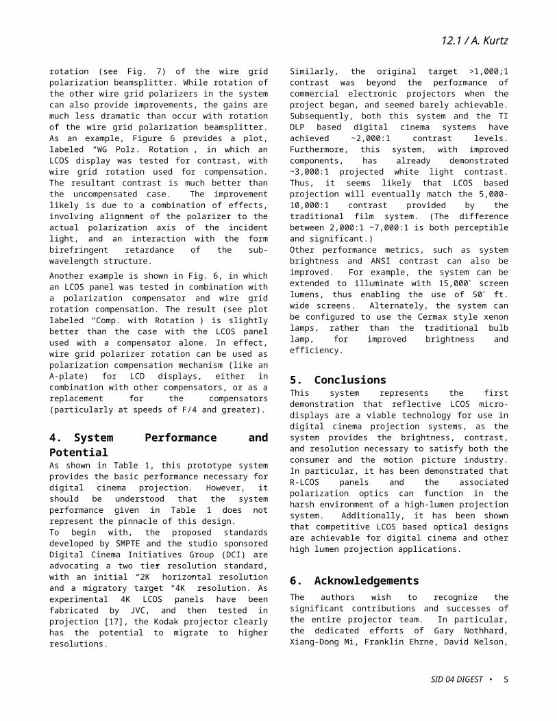
Moxtek has continuously improved these devices, providing both protective coatings and improved flatness for imaging applications [7]. Moreover, improvements to wire grid polarizers are possible, for example to enhance blue contrast or to increase reflected and transmitted contrast, by decreasing the wire pitch or with multi-layer structures [8] (see Figure 4).
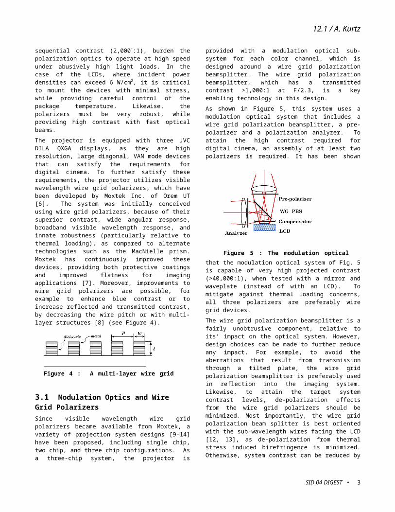
3.1 Modulation Optics and Wire Grid PolarizersSince visible wavelength wire grid polarizers became available from Moxtek, a variety of projection system designs [9-14] have been proposed, including single chip, two chip, and three chip configurations. As a three-chip system, the projector is provided with a modulation optical sub-system for each color channel, which is designed around a wire grid polarization beamsplitter. The wire grid polarization beamsplitter, which has a transmitted contrast >1,000:1 at F/2.3, is a key enabling technology in this design. As shown in Figure 5, this system uses a modulation optical system that includes a wire grid polarization beamsplitter, a pre-polarizer and a polarization analyzer. To attain the high contrast required for digital cinema, an assembly of at least two polarizers is required. It has been shown that the modulation optical system of Fig. 5 is capable of very high projected contrast (>40,000:1), when tested with a mirror and waveplate (instead of with an LCD). To mitigate against thermal loading concerns, all three polarizers are preferably wire grid devices.
The wire grid polarization beamsplitter is a fairly unobtrusive component, relative to its’ impact on the optical system. However, design choices can be made to further reduce any impact. For example, to avoid the aberrations that result from transmission through a tilted plate, the wire grid polarization beamsplitter is preferably used in reflection into the imaging system. Likewise, to attain the target system contrast levels, de-polarization effects from the wire grid polarizers should be minimized. Most importantly, the wire grid polarization beam splitter is best oriented with the sub-wavelength wires facing the LCD [12, 13], as de-polarization from thermal stress induced birefringence is minimized. Otherwise, system contrast can be reduced by as
• SID 04 DIGEST2
Figure 5 : The modulation optical system [13, 15].
Figure 4 : A multi-layer wire grid polarizer [8].
Figure 3 : The V-prism Combiner
12.1 / A. Kurtz
much as ~10X. Due to their wide angular response, particularly as compared to the traditional MacNielle prism, wire grid polarizers have been perceived as not contributing any skew ray de-polarization effects. Indeed, the wire grid polarization beamsplitter can be considered to be partially self compensating [15], when it is used in both transmission and reflection, such as in the modulation optical system of Fig. 5. In particular, this is because the wire grid polarization beamsplitter can be classified as an E-type polarizer in transmission (transmits the extraordinary ray) and O-type polarizer in reflection (reflects the ordinary ray). In actuality, wire grid polarizers still can cause small skew ray de-polarization effects [15], which can become important as LCOS projection systems strive for ever higher levels of contrast and brightness performance.
3.2 Polarization Compensation As shown in Fig. 5, this system is equipped with a polarization compensator, which is nominally located between the LCD and the wire grid polarization beamsplitter. This compensator can be designed to provide polarization state correction for the LCD panel, the wire grid polarization beamsplitter, or for the two in combination [13, 15]. The compensator, which can be fabricated from stretched polymer materials, liquid crystal polymers, or inorganic materials, typically provides a combination of in-plane (A-plate) and out-of-plane (C-plate) retardances. With respect to the LCD panel, the in-plane retardance is utilized to correct any residual birefringence within the device, while the out-of plane retardance corrects for angular response variations (F# dependent). Compensation for the wire grid polarizers may also have both A-plate and C-plate portions, and is largely F# dependent.To better appreciate the value of polarization compensation and its relevance to the modulation optical system of Fig. 5, Figure 6 shows plots of contrast vs. illumination F# under different test conditions as measured in a bench set-up. Note that low contrast (~400:1) is achieved when a VAN LCOS panel is used with the
polarizers, but without any polarization compensation (see plot labeled “uncompensated”). However, when an optimized compensator is used, the performance improves dramatically (2,100:1 CR at F/2.3, per plot labeled “compensated”). Contrast might be expected to increase more dramatically vs. F# than shown, but the measured contrast depends on the actual display and compensator, as well as the interaction of the diffracted orders and the collection aperture (fixed at F/2.3 for this data).
In actual use, the compensator is mounted in close proximity to the LCOS panel, and is then rotated to optimize the contrast performance, on the basis of the peak contrast and the contrast uniformity achieved. While the bench measurements and the system measurements of contrast don’t correlate exactly, a measured white light on screen contrast above 2,200:1 at F/2.3 is typical for this system.
3.3 Wire Grid Polarizers As CompensatorsIt has also been demonstrated [16] that system contrast can be improved significantly by means of a small in-plane rotation (see Fig. 7) of the wire grid polarization beamsplitter. While rotation of the other wire grid polarizers in the system can also provide improvements, the gains are much less dramatic than occur with rotation of the wire grid polarization beamsplitter. As an example, Figure 6 provides a plot, labeled “WG Polz. Rotation”, in which an LCOS display was tested for contrast, with wire grid rotation used for compensation. The resultant contrast is much better than the uncompensated case. The improvement likely is due to a combination of effects, involving alignment of the polarizer to the actual polarization axis of the incident light, and an interaction with the form birefringent retardance of the sub-wavelength structure.
Another example is shown in Fig. 6, in which an LCOS panel was tested in combination with a polarization compensator and wire grid rotation compensation. The result (see plot labeled “Comp. with Rotation”) is slightly better than the case with the LCOS panel used with a compensator alone. In effect, wire grid polarizer rotation can be used as polarization compensation mechanism (like an A-plate) for LCD displays, either in combination with other compensators, or as a replacement for the compensators (particularly at speeds of F/4 and greater).
4. System Performance and PotentialAs shown in Table 1, this prototype system provides the basic performance necessary for digital cinema projection. However, it should be understood that the system performance given in Table 1 does not represent the pinnacle of this design. To begin with, the proposed standards developed by SMPTE and the studio sponsored Digital Cinema Initiatives Group (DCI) are advocating a two tier resolution standard, with an initial “2K” horizontal resolution and a migratory target “4K” resolution. As experimental 4K LCOS panels have been fabricated by JVC, and then tested in projection [17], the Kodak projector clearly has the potential to migrate to higher resolutions.
SID 04 DIGEST • 3
Figure 6 : Polarization Contrast vs. F# [15, 16].
Figure 7 : Wire Grid Rotation for Polarization Compensation [16].

12.1 / A. Kurtz
Similarly, the original target >1,000;1 contrast was beyond the performance of commercial electronic projectors when the project began, and seemed barely achievable. Subsequently, both this system and the TI DLP based digital cinema systems have achieved ~2,000:1 contrast levels. Furthermore, this system, with improved components, has already demonstrated ~3,000:1 projected white light contrast. Thus, it seems likely that LCOS based projection will eventually match the 5,000-10,000:1 contrast provided by the traditional film system. (The difference between 2,000:1 ~7,000:1 is both perceptible and significant.)Other performance metrics, such as system brightness and ANSI contrast can also be improved. For example, the system can be extended to illuminate with 15,000+ screen lumens, thus enabling the use of 50+ ft. wide screens. Alternately, the system can be configured to use the Cermax style xenon lamps, rather than the traditional bulb lamp, for improved brightness and efficiency.
5. ConclusionsThis system represents the first demonstration that reflective LCOS micro-displays are a viable technology for use in digital cinema projection systems, as the system provides the brightness, contrast, and resolution necessary to satisfy both the consumer and the motion picture industry. In particular, it has been demonstrated that R-LCOS panels and the associated polarization optics can function in the harsh environment of a high-lumen projection system. Additionally, it has been shown that competitive LCOS based optical designs are achievable for digital cinema and other high lumen projection applications.
6. AcknowledgementsThe authors wish to recognize the significant contributions and successes of the entire projector team. In particular, the dedicated efforts of Gary Nothhard, Xiang-Dong Mi, Franklin Ehrne, David Nelson, James Stoops, William Markis, and Richard Wagner deserve special mention. The Entertainment Imaging Division, and in particular, Richard Sehlin and Leslie Moore, also merit recognition for their continuing support.
7. References [1] L. Hornbeck, D. Darrow, H. Pettitt, B. Walker, and B.
Werner, DLP Cinema Projectors – Enabling Digital Cinema, SID Digest 2000, pgs. 314-317.
[2] R. Sterling and W. Bleha, Electronic Cinema Using ILA Projector Technology, SID Digest 1999, pgs. 216-219.
[3] R. Sterling and W. Bleha, DILA Technology for Electronic Cinema, SID Digest 2000, pgs. 310-313.
[4] C. DuMont, A. Kurtz, B. Silverstein, and D. Kirkpatrick, Design Improvements for Motion Picture Film Projectors, SMPTE Journal, vol. 110, pp. 785-791, Nov. 2001.
[5] J. Cobb and D. Kessler, Projection Apparatus using Spatial Light Modulator with Relay Lens and Dichroic Combiner, U.S. Patent 6,676,260, 2004.
[6] D. Hansen, R. Perkins, and E. Gardner, Broad Band Wire Grid Polarizing Beam Splitter for use in the Visible Wavelength Region, U.S. Patent 6,243,199, 2001.
[7] D. Hansen, E. Gardner, R. Perkins, M. Lines, and A. Robbins, The Display Applications and Physics of the ProFlux Wire Grid Polarizer, SID 2002 Digest, pgs. 730-733.
[8] A. Kurtz, S. Ramanujan, and X.D. Mi, Wire Grid Polarizer, US Patent 6,532,111, 2003.
[9] D. Hansen, R. Perkins, E. Gardner, and M. Lund, Image Projection System with a Polarizing Beam Splitter, U.S. Patent 6,234,634, 2001.
[10] S. Arnold, E. Gardner, D. Hansen, and R. Perkins, An Improved Polarizing Beamsplitter LCOS Projection Display Based on Wire-Grid Polarizers, SID Digest 2001, pgs. 1282-1285.
[11] E. Gardner and D. Hansen, An Image Quality Wire-Grid Polarizing Beam Splitter, SID Digest 2003, pgs. 62-65.
[12] J. Shimizu, P. Janssen, and S. McClain, Digital Image Projector with Oriented Fixed Polarization Axis Polarizing Beamsplitter; U.S. Patent 6,511,183, 2003.
[13] A. Kurtz, J. Cobb, D. Kessler, B. Silverstein, and M. Harrigan, Digital Cinema Projector, U.S. Patent 6,585,378, 2003.
[14] C. Pentico, M. Newell, and M. Greenberg, Ultra High Contrast Color Management System for Projection Displays, SID Digest 2003, pgs. 130-133.
[15] X. D. Mi, A. Kurtz, and D. Kessler, Display Apparatus using a Wire Grid Polarizing Beamsplitter with Compensator, U.S. Patent Pub. No. 2003/0128320, 2003.
[16] B. Silverstein, G. Nothhard, A. Kurtz, and X. D. Mi, Projection Display using a Wire Grid Polarization Beamsplitter with Compensator, U.S. Patent Pub. No. 2003/0227597, 2003.
[17] K. Hamada, M. Kanazawa, I. Kondoh, F. Okono, Y. Haino, M. Sato, and K. Doi, A Wide Screen Projector of 4k x 8k
• SID 04 DIGEST4
Light Source 6 kW Xenon arc
Brightness/luminous Output 12,000 screen lumens
Screen Luminance 12 ft-L
Screen Uniformity ~85 %
Frame Sequential Screen Contrast (white)
~2,200:1
ANSI Contrast ~150:1
Color Temperature ~ 5500 to 6100 oK
Imager JVC QXGA DILA; 1.3" diag., 2048 x 1536 px, 1.33:1 aspect ratio
Imager Aperture Ratio (“Flat” - 1.85:1) with anamorphic lens
Light Collection F/2.3 at LCDs
Projection Lens 2.0:1 theatre to screen ratio; others can be readily designed
Image Distortion < 2%
Frame Rate 24 fps effective, 96 Hz repeated
Data 10 bits log/color, 12 bit resolution
Data Standards supported SMPTE 292M, HDTV, SDTV
Table 1 : Digital Cinema Projector Technical Specifications
12.1 / A. Kurtz
Pixels, SID 2002 Digest, pgs. 1254-1257.
SID 04 DIGEST • 5