09 frequency stab
TRANSCRIPT
8/12/2019 09 Frequency Stab
http://slidepdf.com/reader/full/09-frequency-stab 1/49
Copyright © P. Kundur
This material should not be used without the author's consent1539pk
FREQUENCY STABILITY
8/12/2019 09 Frequency Stab
http://slidepdf.com/reader/full/09-frequency-stab 2/49
FS - 11539pk
Frequency Stability
Outline
Nature and description of frequency stability
problems
Examples of frequency instability incidents
Analytical techniques for investigation of
frequency stability problems
Case studies
Mitigation of frequency stability problems
8/12/2019 09 Frequency Stab
http://slidepdf.com/reader/full/09-frequency-stab 3/49
FS - 21539pk
Frequency Stability
Ability to maintain a steady frequency within anominal range, following a disturbance resulting in asignificant imbalance between system generationand load
of interest is the overall response as evidenced bymean frequency, rather than relative motions of
machines
In a small "island" system, frequency stability couldbe of concern for any disturbance causing asignificant loss of load or generation
In a large interconnected system, frequency stabilitycould be of concern only following a severe system
upset resulting in the system splitting into one ormore islands
Depends on the ability to restore balance betweengeneration and load of island systems with minimumloss of load and generation
Generally, frequency stability problems are
associated with inadequacies in equipmentresponses, poor coordination of control andprotection systems
8/12/2019 09 Frequency Stab
http://slidepdf.com/reader/full/09-frequency-stab 4/49
FS - 31539pk
System Response to Generation/Load
Imbalance
Results in sustained frequency deviations
speed control and the subsequent responses of
prime mover and energy supply systems play a
major role
often, situation compounded by high- or low-voltageconditions
Undergenerated condition:
frequency will decline
if sufficient spinning generation reserve is not
available, frequency may reach low levels at whichthermal units are tripped by underfrequency
protection
therefore, underfrequency load shedding used
Overgenerated condition:
speed governors respond to frequency rise
performance of island depends on the ability of
power plants to sustain a "partial load rejection"
8/12/2019 09 Frequency Stab
http://slidepdf.com/reader/full/09-frequency-stab 5/49
FS - 41539pk
System Response to Generation/Load
Imbalance (cont'd)
Reactive power balance:
a significant mismatch could lead to high- or low-
voltage conditions
generator under/over excitation, loss-of-excitation
protections may be activated
Powerplant auxiliaries:
decrease in power supply voltage and frequency can
degrade performance of induction motors
may lead to loss of condenser vacuum, high turbine-
exhaust temperature, insufficientcondensate/feedwater
many nuclear units are equipped with relays set to
trip plant at low voltages (0.7 pu) and low frequency
Power system loads respond to variations in voltage
and frequency
8/12/2019 09 Frequency Stab
http://slidepdf.com/reader/full/09-frequency-stab 6/49
FS - 51539pk
Protections and Controls
Following protection/controls have significant
influence:
Prime mover/energy supply system
turbine overspeed control
turbine underfrequency protection
power plant auxiliaries protection
Generator and excitation system
loss-of-excitation relay
under/overexcitation limiter
volts/Hz limiter and protection
Electrical network
transmission and distribution system relays
underfrequency and undervoltage load shedding
relays
8/12/2019 09 Frequency Stab
http://slidepdf.com/reader/full/09-frequency-stab 7/49
FS - 61539pk
Frequency Instability Incidents
1. April 19, 1972 disturbances in Ontario
islanding of Eastern Ontario
2. January 20, 1974 disturbance
islanding of Toronto area
3. February 13, 1978 disturbance causing separation of
portions of Missouri and Illinois systems
8/12/2019 09 Frequency Stab
http://slidepdf.com/reader/full/09-frequency-stab 8/49
FS - 71539pk
April 19, 1972 Disturbance: Eastern Ontario
Incident:
230 kV lines east of Toronto tripped due to
communication malfunction; ties to New York at St.
Lawrence tripped
generation rich island formed in eastern Ontario(G = 3900 MW, L = 3000 MW)
frequency rose to 62.5 Hz and then dropped to 59.0
Hz due to speed governor
underfrequency load shedding
frequency rose to 62.6 Hz and dropped to 58.7 Hz significant loss of generation and load
stabilized at 60.8 Hz with 1875 MW generation
Source of problem:
overspeed controls associated with prime-mover
governors of Pickering "A" NGS
8/12/2019 09 Frequency Stab
http://slidepdf.com/reader/full/09-frequency-stab 9/49
FS - 81539pk
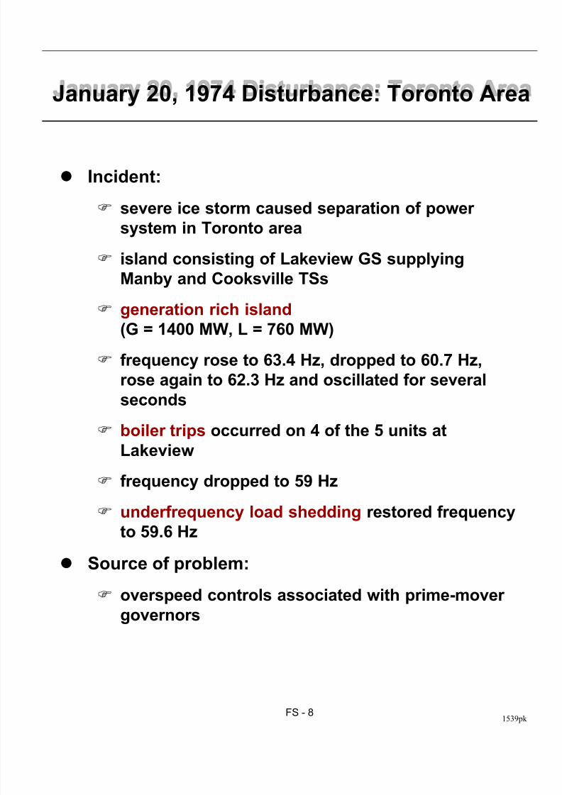
January 20, 1974 Disturbance: Toronto Area
Incident:
severe ice storm caused separation of power
system in Toronto area
island consisting of Lakeview GS supplying
Manby and Cooksville TSs
generation rich island
(G = 1400 MW, L = 760 MW)
frequency rose to 63.4 Hz, dropped to 60.7 Hz,
rose again to 62.3 Hz and oscillated for several
seconds
boiler trips occurred on 4 of the 5 units at
Lakeview
frequency dropped to 59 Hz
underfrequency load shedding restored frequency
to 59.6 Hz
Source of problem:
overspeed controls associated with prime-mover
governors
8/12/2019 09 Frequency Stab
http://slidepdf.com/reader/full/09-frequency-stab 10/49
FS - 91539pk
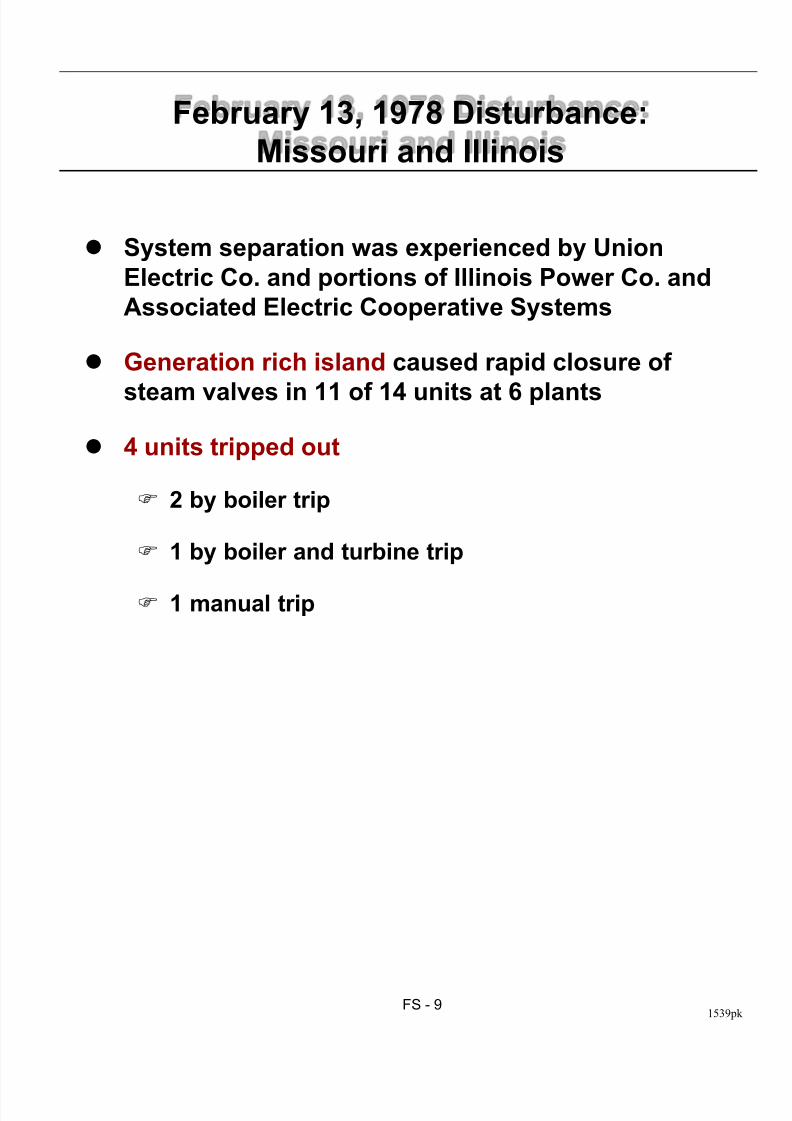
February 13, 1978 Disturbance:
Missouri and Illinois
System separation was experienced by Union
Electric Co. and portions of Illinois Power Co. and
Associated Electric Cooperative Systems
Generation rich island caused rapid closure of
steam valves in 11 of 14 units at 6 plants
4 units tripped out
2 by boiler trip
1 by boiler and turbine trip
1 manual trip
8/12/2019 09 Frequency Stab
http://slidepdf.com/reader/full/09-frequency-stab 11/49
FS - 101539pk
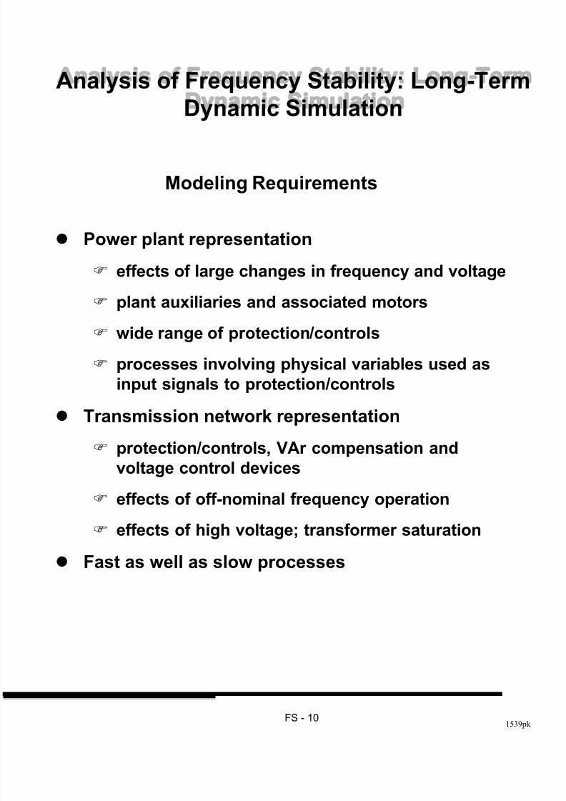
Analysis of Frequency Stability: Long-Term
Dynamic Simulation
Modeling Requirements
Power plant representation
effects of large changes in frequency and voltage
plant auxiliaries and associated motors
wide range of protection/controls
processes involving physical variables used as
input signals to protection/controls
Transmission network representation protection/controls, VAr compensation and
voltage control devices
effects of off-nominal frequency operation
effects of high voltage; transformer saturation
Fast as well as slow processes
8/12/2019 09 Frequency Stab
http://slidepdf.com/reader/full/09-frequency-stab 12/49
FS - 111539pk
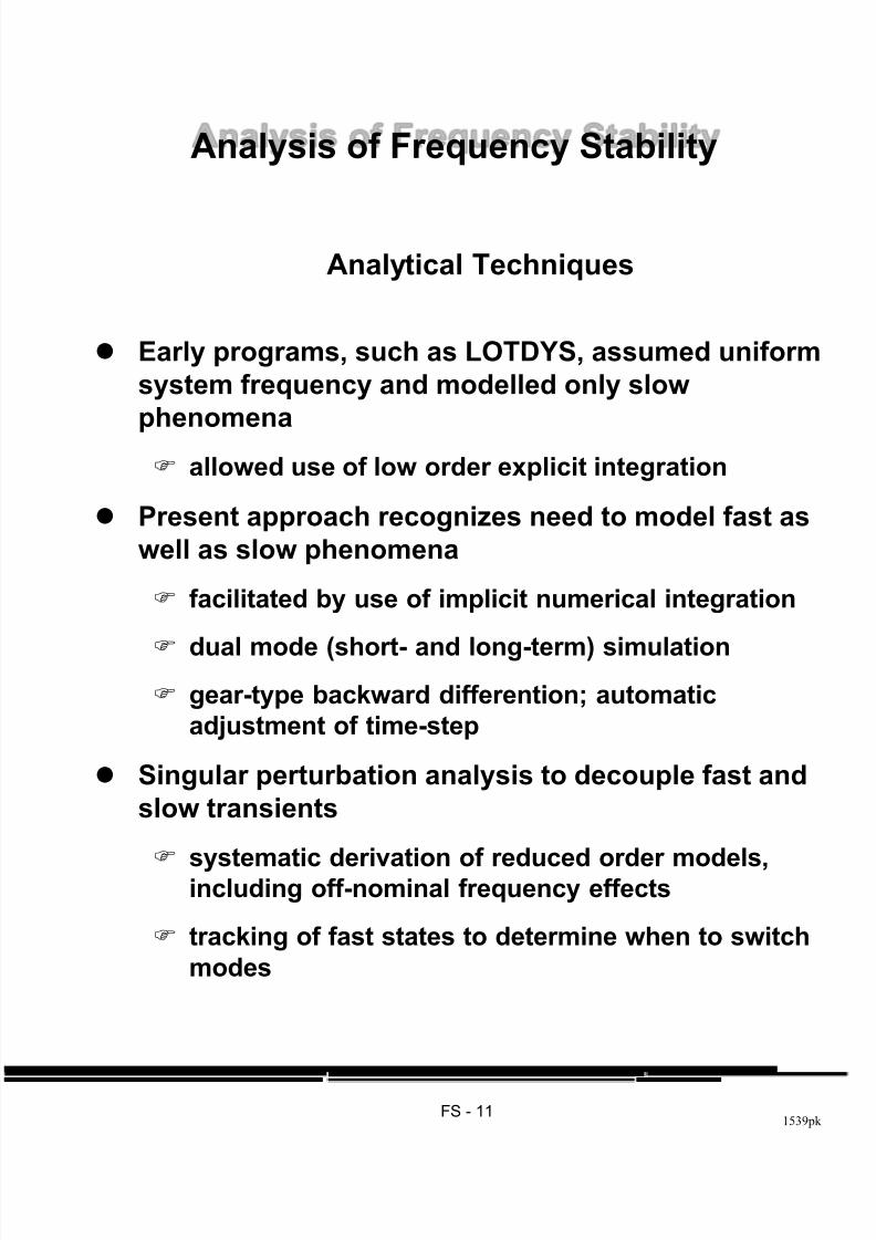
Analysis of Frequency Stability
Analytical Techniques
Early programs, such as LOTDYS, assumed uniform
system frequency and modelled only slow
phenomena
allowed use of low order explicit integration
Present approach recognizes need to model fast as
well as slow phenomena
facilitated by use of implicit numerical integration
dual mode (short- and long-term) simulation
gear-type backward differention; automatic
adjustment of time-step
Singular perturbation analysis to decouple fast and
slow transients
systematic derivation of reduced order models,including off-nominal frequency effects
tracking of fast states to determine when to switch
modes

8/12/2019 09 Frequency Stab
http://slidepdf.com/reader/full/09-frequency-stab 13/49
FS - 121539pk
Long-Term Stability Program (LTSP)
Fossil-fuelled plant: furnace, fuel system,
secondary air system, flue gas system, feedwater
system, boiler, main and reheat system, control
and protection systems, auxiliaries
Nuclear plant (PWR, BWR, CANDU): reactor core,
primary heat transport system, steam generator,
feedwater system, main and reheat steam system,
control and protection, auxiliaries
Based on ETMSP; modelling extended to include the
following:
8/12/2019 09 Frequency Stab
http://slidepdf.com/reader/full/09-frequency-stab 14/49
FS - 131539pk
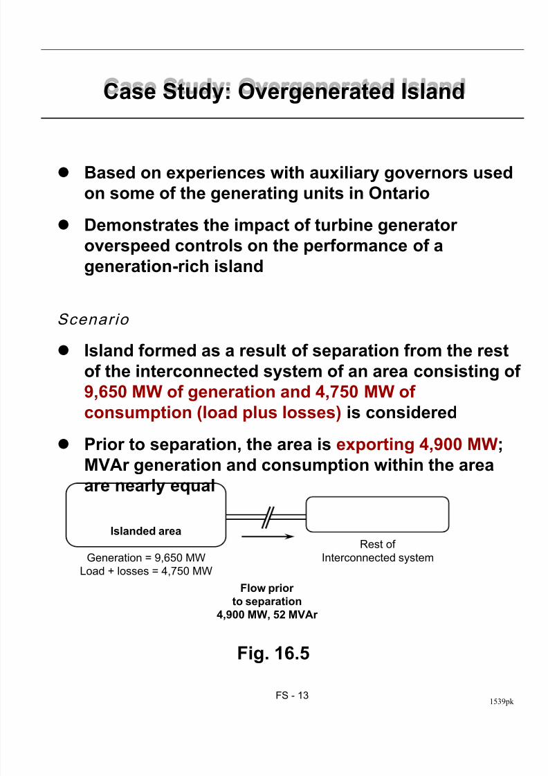
Case Study: Overgenerated Island
Based on experiences with auxiliary governors used
on some of the generating units in Ontario
Demonstrates the impact of turbine generator
overspeed controls on the performance of a
generation-rich island
Scenario
Island formed as a result of separation from the rest
of the interconnected system of an area consisting of
9,650 MW of generation and 4,750 MW of
consumption (load plus losses) is considered
Prior to separation, the area is exporting 4,900 MW;
MVAr generation and consumption within the area
are nearly equal
Fig. 16.5
Flow prior
to separation
4,900 MW, 52 MVAr
Rest ofInterconnected system
Islanded area
Generation = 9,650 MW
Load + losses = 4,750 MW
8/12/2019 09 Frequency Stab
http://slidepdf.com/reader/full/09-frequency-stab 15/49
FS - 141539pk
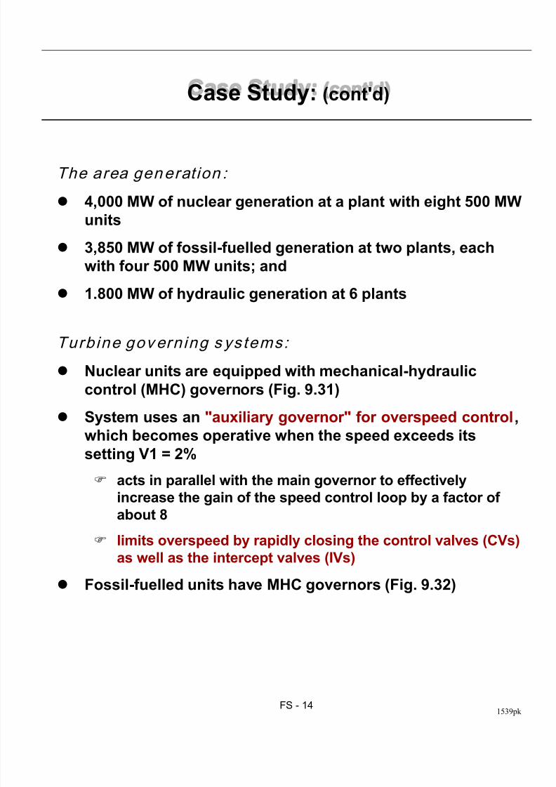
Case Study: (cont'd)
The area generation :
4,000 MW of nuclear generation at a plant with eight 500 MW
units
3,850 MW of fossil-fuelled generation at two plants, each
with four 500 MW units; and
1.800 MW of hydraulic generation at 6 plants
Turb ine govern ing s ystems:
Nuclear units are equipped with mechanical-hydraulic
control (MHC) governors (Fig. 9.31)
System uses an "auxiliary governor" for overspeed control,which becomes operative when the speed exceeds its
setting V1 = 2%
acts in parallel with the main governor to effectively
increase the gain of the speed control loop by a factor of
about 8
limits overspeed by rapidly closing the control valves (CVs)
as well as the intercept valves (IVs)
Fossil-fuelled units have MHC governors (Fig. 9.32)
8/12/2019 09 Frequency Stab
http://slidepdf.com/reader/full/09-frequency-stab 16/49
FS - 151539pk
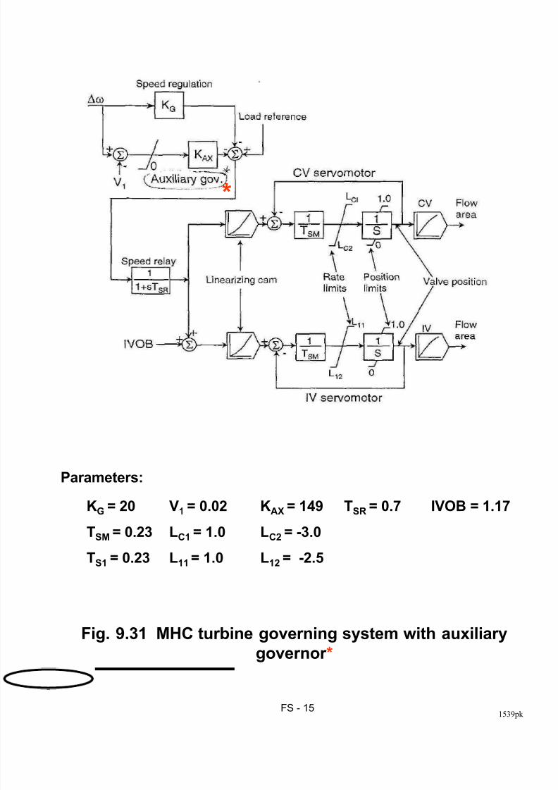
KG = 20 V1 = 0.02 KAX = 149 TSR = 0.7 IVOB = 1.17
TSM = 0.23 LC1 = 1.0 LC2 = -3.0
TS1 = 0.23 L11 = 1.0 L12 = -2.5
Fig. 9.31 MHC turbine governing system with auxiliary
governor *
*
Parameters:
8/12/2019 09 Frequency Stab
http://slidepdf.com/reader/full/09-frequency-stab 17/49
FS - 161539pk
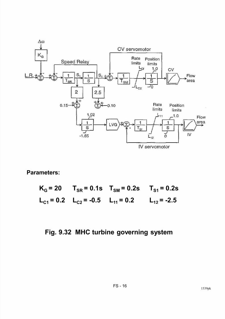
KG = 20 TSR = 0.1s TSM = 0.2s TS1 = 0.2s
LC1 = 0.2 LC2 = -0.5 L11 = 0.2 L12 = -2.5
Fig. 9.32 MHC turbine governing system
Parameters:
8/12/2019 09 Frequency Stab
http://slidepdf.com/reader/full/09-frequency-stab 18/49
FS - 171539pk
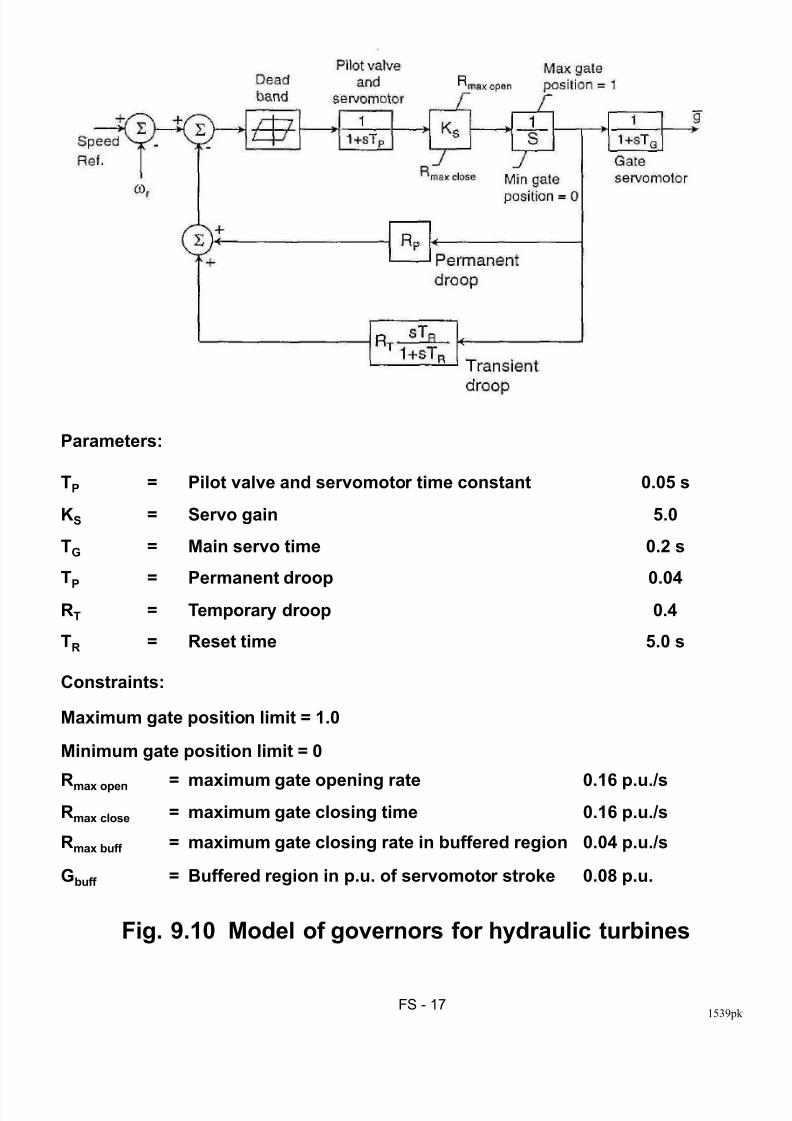
Parameters:
TP = Pilot valve and servomotor time constant 0.05 s
KS = Servo gain 5.0
TG = Main servo time 0.2 s
TP
= Permanent droop 0.04
RT = Temporary droop 0.4
TR = Reset time 5.0 s
Constraints:
Maximum gate position limit = 1.0
Minimum gate position limit = 0
Rmax open = maximum gate opening rate 0.16 p.u./sRmax close = maximum gate closing time 0.16 p.u./s
Rmax buff = maximum gate closing rate in buffered region 0.04 p.u./s
Gbuff = Buffered region in p.u. of servomotor stroke 0.08 p.u.
Fig. 9.10 Model of governors for hydraulic turbines
8/12/2019 09 Frequency Stab
http://slidepdf.com/reader/full/09-frequency-stab 19/49
FS - 181539pk
Case Study: (cont'd)
Simulat ion
Simulated by simultaneous opening of all ties
connecting the area to the rest of the system
resulting in an island with generation nearly twice
the load
Generators and excitation system are represented
in detail
Loads are represented as nonlinear functions of
voltage and frequency
Performance of the islanded system is examinedwith the auxiliary governors of the nuclear units in-
service and out-of-service
8/12/2019 09 Frequency Stab
http://slidepdf.com/reader/full/09-frequency-stab 20/49
FS - 191539pk
Case Study: (cont'd)
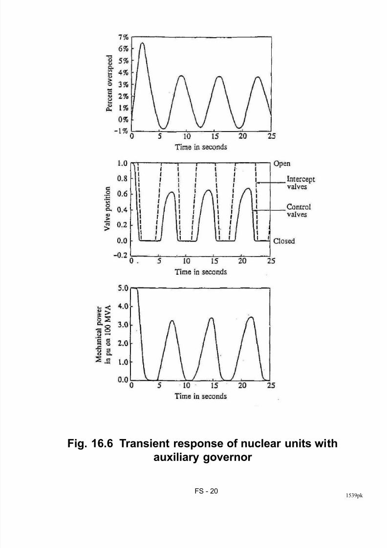
a) With aux i liary governor in-serv ice:
Fig. 16.6 shows plots of speed deviation, CV and IV
positions, and mechanical power of one of the
nuclear units
The speed increases rapidly to a maximum ofabout 6.4% above the normal speed of 1,800 rpm
oscillates with little damping between 3.5% above
and 0.7% below the normal speed
Oscillation due to the action of the auxiliary
governors
when the overspeed exceeds the setting V1 of 1%,
the auxiliary governors close the steam valves
and reduce the mechanical power of the nuclear
units to zero
the deficit in the generated power reduces the
speed rapidly, and the valves open again
resultant increase in mechanical power is such
that the speed exceeds the auxiliary governor
setting of 1%, and the valves close again.
cycle repeats with a period of about 7 seconds
8/12/2019 09 Frequency Stab
http://slidepdf.com/reader/full/09-frequency-stab 21/49
FS - 201539pk
Fig. 16.6 Transient response of nuclear units with
auxiliary governor
8/12/2019 09 Frequency Stab
http://slidepdf.com/reader/full/09-frequency-stab 22/49
FS - 211539pk
Case Study: (cont'd)
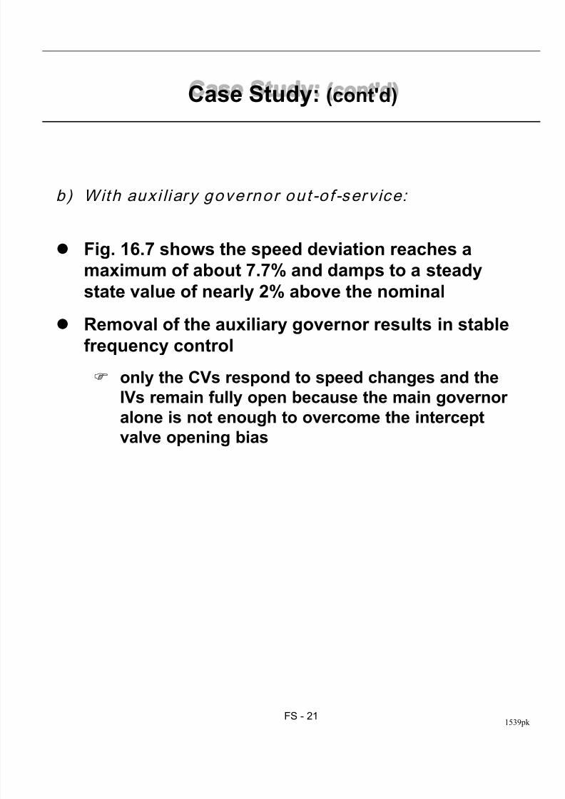
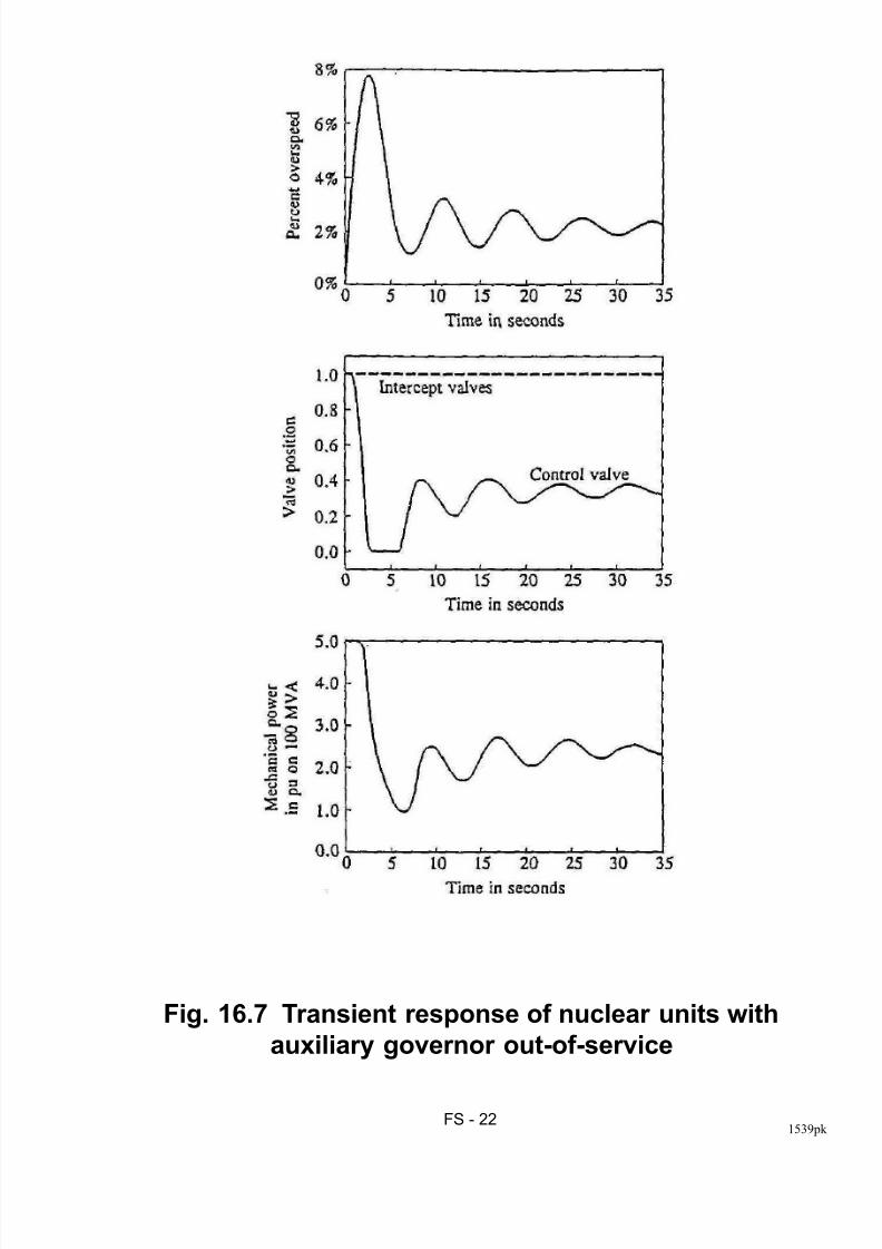
b) With aux i liary governor out -o f -serv ice:
Fig. 16.7 shows the speed deviation reaches a
maximum of about 7.7% and damps to a steady
state value of nearly 2% above the nominal
Removal of the auxiliary governor results in stable
frequency control
only the CVs respond to speed changes and the
IVs remain fully open because the main governor
alone is not enough to overcome the interceptvalve opening bias
8/12/2019 09 Frequency Stab
http://slidepdf.com/reader/full/09-frequency-stab 23/49
FS - 221539pk
Fig. 16.7 Transient response of nuclear units with
auxiliary governor out-of-service
8/12/2019 09 Frequency Stab
http://slidepdf.com/reader/full/09-frequency-stab 24/49
FS - 231539pk
Case Study: (cont'd)
Conc lus ions
The auxiliary governors cause instability of the
speed control during system islanding conditions
other units in the island respond to oscillations of
the units with auxiliary governors
causes oscillations of all units
resulting movements of steam valves or wicket
gates continue until the hydraulic systems of the
governors run out of oil, causing unit tripping and
possibly a blackout of the island
oscillations may also give rise to "priming" of the
boilers of the fossil-fired units, causing water from
the boilers to come in contact with the high
temperature superheat and HP stages
One solution is to replace the auxiliary governor with
an electronic acceleration detector
8/12/2019 09 Frequency Stab
http://slidepdf.com/reader/full/09-frequency-stab 25/49
FS - 241539pk
Mitigation of Frequency Stability Problems
More emphasis on appropriate setting andcoordination of protections and controls
protective systems should recognize not onlyequipment safety but also power systemperformance requirements
Design of power plants so as to be able tosuccessfully withstand "partial load rejections" andislanding conditions
achieved by proper design of overall plant control,boiler/reactor control, and turbine overspeedcontrol; and
ensuring vital auxiliaries will not trip out due to thevoltage and frequency variations
A well designed underfrequency load sheddingscheme
selection of possible areas of separation and loadblocks for shedding
due consideration to power plant and networkprotections/controls
recognition of requirement for adequate voltage andreactive power control
8/12/2019 09 Frequency Stab
http://slidepdf.com/reader/full/09-frequency-stab 26/49
FS - 251539pk
IEEE and CIGRE Reports on Major
Frequency Disturbances
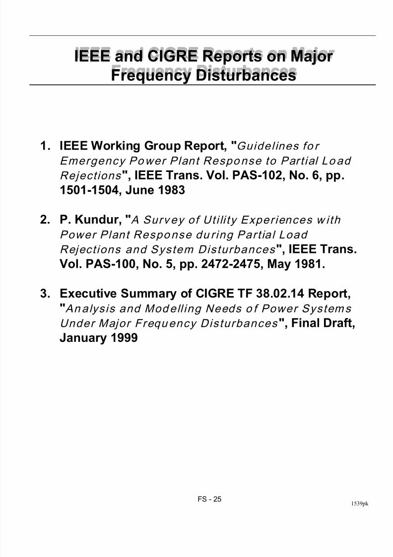
1. IEEE Working Group Report, "Guidel ines fo r
Emergency Power Plant Response to Part ial Lo ad
Reject ions ", IEEE Trans. Vol. PAS-102, No. 6, pp.
1501-1504, June 1983
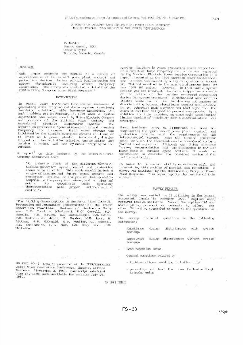
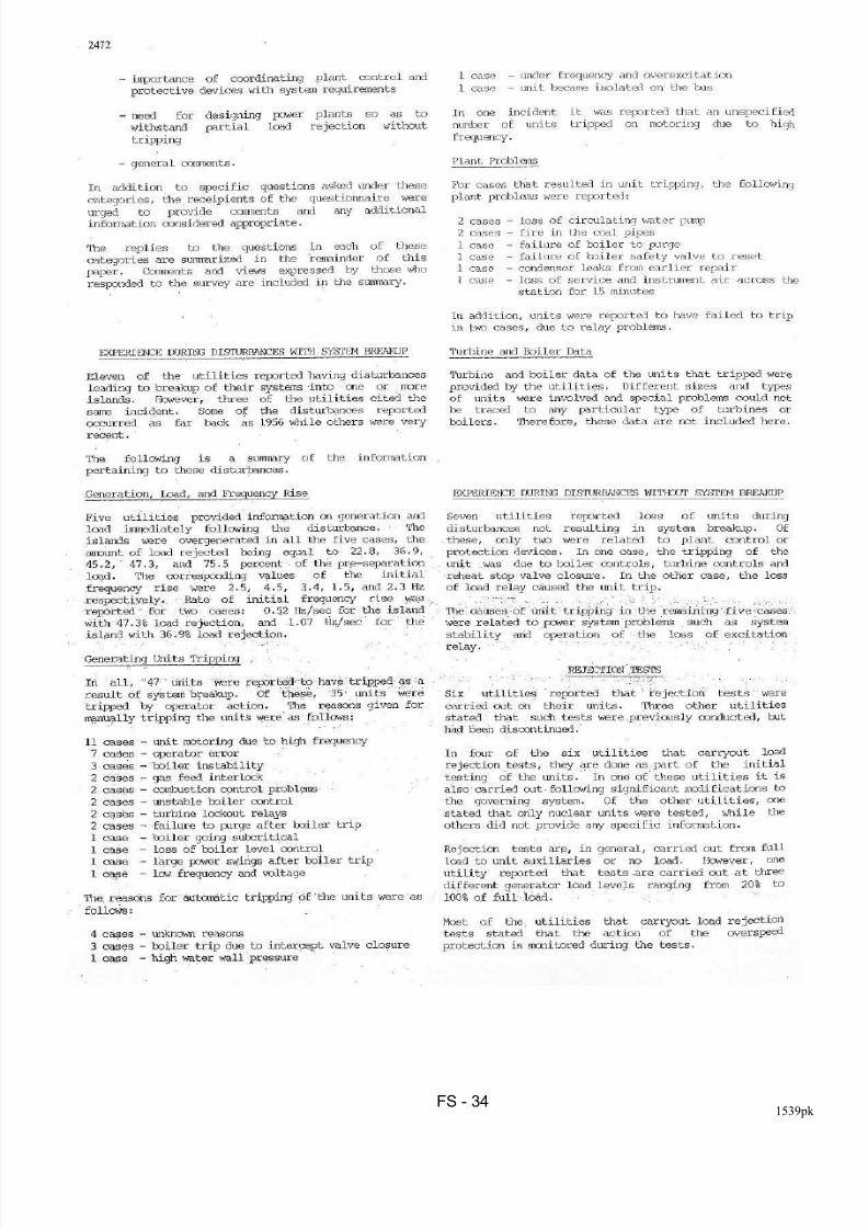
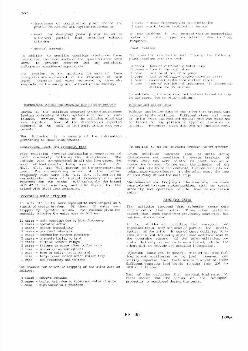
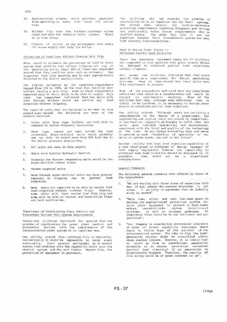
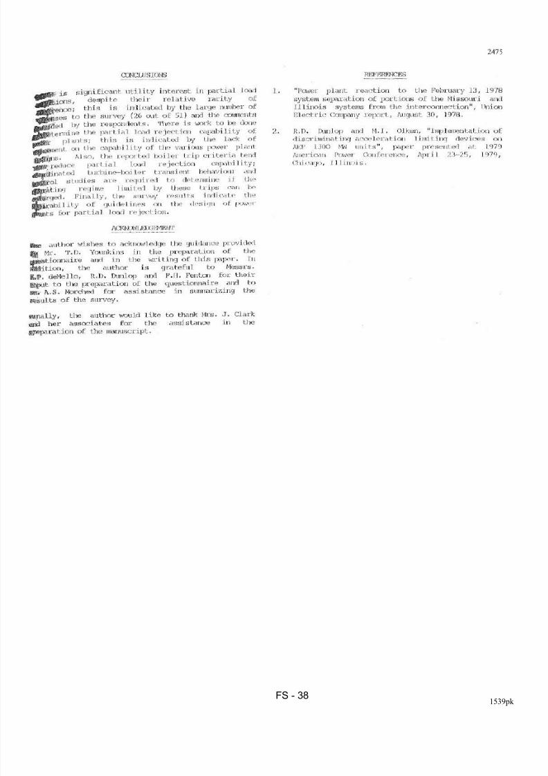
2. P. Kundur, "A Surv ey of Uti li ty Exper iences w ith
Power Plant Response du r ing Part ia l Load
Reject ions and System Disturbances ", IEEE Trans.
Vol. PAS-100, No. 5, pp. 2472-2475, May 1981.
3. Executive Summary of CIGRE TF 38.02.14 Report,"Analysis and Modell ing Needs o f Power Systems
Under Major Frequency Disturbances ", Final Draft,
January 1999
8/12/2019 09 Frequency Stab
http://slidepdf.com/reader/full/09-frequency-stab 27/49
FS - 261539pk
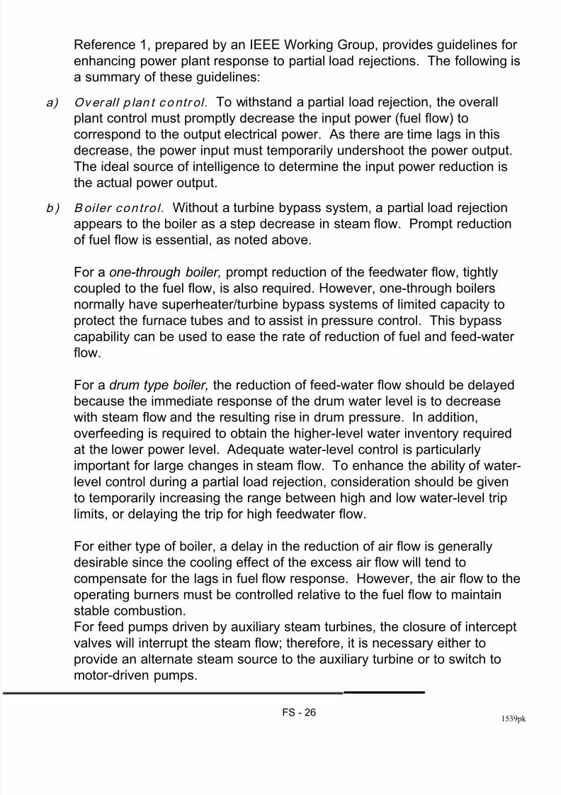
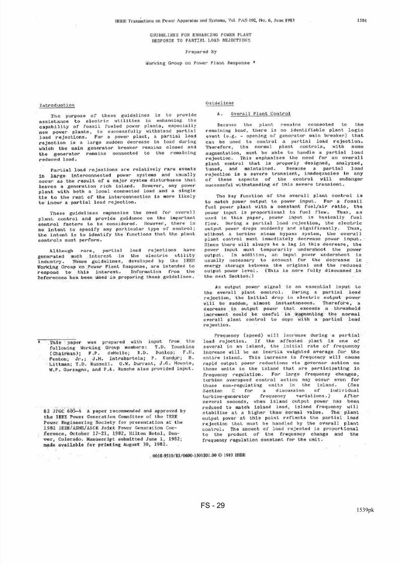
Reference 1, prepared by an IEEE Working Group, provides guidelines for
enhancing power plant response to partial load rejections. The following is
a summary of these guidelines:
a) Over al l p lan t contr ol. To withstand a partial load rejection, the overall
plant control must promptly decrease the input power (fuel flow) to
correspond to the output electrical power. As there are time lags in thisdecrease, the power input must temporarily undershoot the power output.
The ideal source of intelligence to determine the input power reduction is
the actual power output.
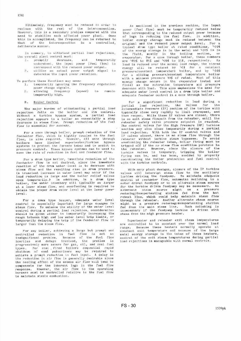
b ) B oiler con tro l. Without a turbine bypass system, a partial load rejection
appears to the boiler as a step decrease in steam flow. Prompt reduction
of fuel flow is essential, as noted above.
For a one-through boiler, prompt reduction of the feedwater flow, tightlycoupled to the fuel flow, is also required. However, one-through boilers
normally have superheater/turbine bypass systems of limited capacity to
protect the furnace tubes and to assist in pressure control. This bypass
capability can be used to ease the rate of reduction of fuel and feed-water
flow.
For a drum type boiler, the reduction of feed-water flow should be delayed
because the immediate response of the drum water level is to decrease
with steam flow and the resulting rise in drum pressure. In addition,overfeeding is required to obtain the higher-level water inventory required
at the lower power level. Adequate water-level control is particularly
important for large changes in steam flow. To enhance the ability of water-
level control during a partial load rejection, consideration should be given
to temporarily increasing the range between high and low water-level trip
limits, or delaying the trip for high feedwater flow.
For either type of boiler, a delay in the reduction of air flow is generally
desirable since the cooling effect of the excess air flow will tend to
compensate for the lags in fuel flow response. However, the air flow to the
operating burners must be controlled relative to the fuel flow to maintain
stable combustion.
For feed pumps driven by auxiliary steam turbines, the closure of intercept
valves will interrupt the steam flow; therefore, it is necessary either to
provide an alternate steam source to the auxiliary turbine or to switch to
motor-driven pumps.
8/12/2019 09 Frequency Stab
http://slidepdf.com/reader/full/09-frequency-stab 28/49
FS - 271539pk
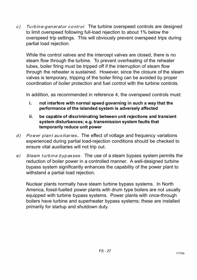
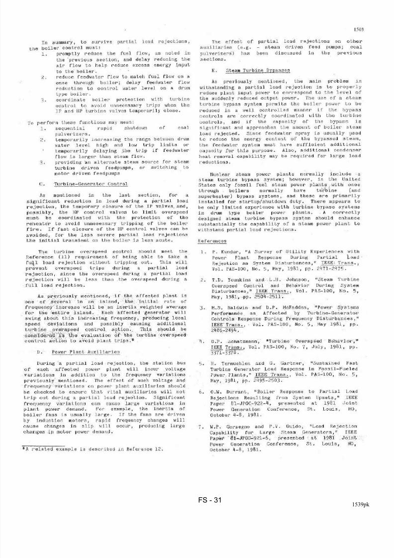
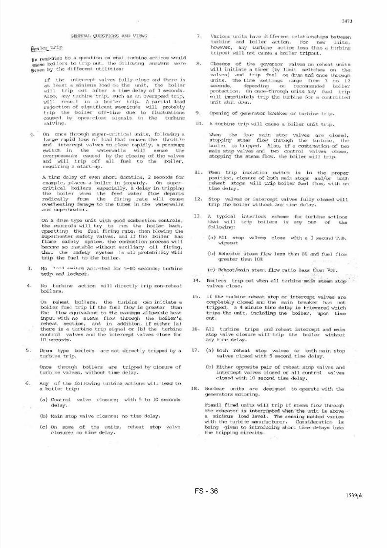
c ) Tu rb in e-g ener at or contr ol. The turbine overspeed controls are designed
to limit overspeed following full-load rejection to about 1% below the
overspeed trip settings. This will obviously prevent overspeed trips during
partial load rejection.
While the control valves and the intercept valves are closed, there is no
steam flow through the turbine. To prevent overheating of the reheater
tubes, boiler firing must be tripped off if the interruption of steam flow
through the reheater is sustained. However, since the closure of the steam
valves is temporary, tripping of the boiler firing can be avoided by proper
coordination of boiler protection and fuel control with the turbine controls.
In addition, as recommended in reference 4, the overspeed controls must:
i. not interfere with normal speed governing in such a way that the
performance of the islanded system is adversely affected
ii. be capable of discriminating between unit rejections and transient
system disturbances; e.g. transmission system faults that
temporarily reduce unit power
d ) Power plan t au x il iar ies . The effect of voltage and frequency variations
experienced during partial load-rejection conditions should be checked to
ensure vital auxiliaries will not trip out.
e) Steam t urb in e b yp as ses . The use of a steam bypass system permits the
reduction of boiler power in a controlled manner. A well-designed turbine
bypass system significantly enhances the capability of the power plant to
withstand a partial load rejection.
Nuclear plants normally have steam turbine bypass systems. In North
America, fossil-fuelled power plants with drum type boilers are not usually
equipped with turbine bypass systems. Power plants with once-throughboilers have turbine and superheater bypass systems; these are installed
primarily for startup and shutdown duty.
8/12/2019 09 Frequency Stab
http://slidepdf.com/reader/full/09-frequency-stab 29/49
FS - 281539pk
Appendix to Section on Frequency Stability
Copies of Papers:
1. Guidelines for Enhancing Power Plant Response to
Partial Load Rejection
2. A Survey of Utility Experiences with Power PlantResponse during partial Load Rejection and
System Disturbances
3. CIGRE TF 38.02.14, Report: "Analysis and Modeling
Needs of Power Systems under Major Frequency
Disturbances
8/12/2019 09 Frequency Stab
http://slidepdf.com/reader/full/09-frequency-stab 30/49
FS - 291539pk
8/12/2019 09 Frequency Stab
http://slidepdf.com/reader/full/09-frequency-stab 31/49
FS - 301539pk
8/12/2019 09 Frequency Stab
http://slidepdf.com/reader/full/09-frequency-stab 32/49
8/12/2019 09 Frequency Stab
http://slidepdf.com/reader/full/09-frequency-stab 33/49
FS - 321539pk
8/12/2019 09 Frequency Stab
http://slidepdf.com/reader/full/09-frequency-stab 34/49
FS - 331539pk
8/12/2019 09 Frequency Stab
http://slidepdf.com/reader/full/09-frequency-stab 35/49
FS - 341539pk
8/12/2019 09 Frequency Stab
http://slidepdf.com/reader/full/09-frequency-stab 36/49
FS - 351539pk
8/12/2019 09 Frequency Stab
http://slidepdf.com/reader/full/09-frequency-stab 37/49
FS - 361539pk
8/12/2019 09 Frequency Stab
http://slidepdf.com/reader/full/09-frequency-stab 38/49
FS - 371539pk
8/12/2019 09 Frequency Stab
http://slidepdf.com/reader/full/09-frequency-stab 39/49
FS - 381539pk
8/12/2019 09 Frequency Stab
http://slidepdf.com/reader/full/09-frequency-stab 40/49
FS - 391539pk

8/12/2019 09 Frequency Stab
http://slidepdf.com/reader/full/09-frequency-stab 41/49
FS - 401539pk
Task Force Members Who Have Actively
Contributed
8/12/2019 09 Frequency Stab
http://slidepdf.com/reader/full/09-frequency-stab 42/49
FS - 411539pk
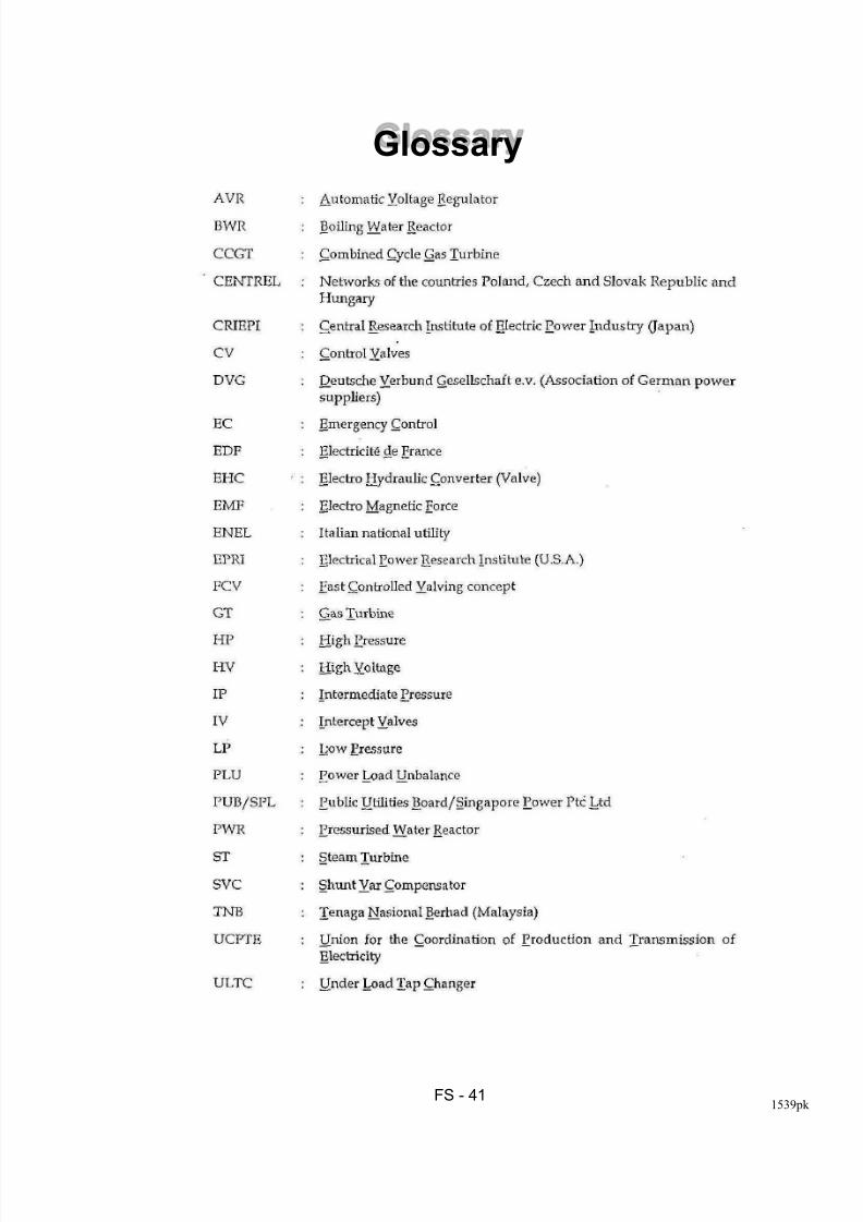
Glossary
8/12/2019 09 Frequency Stab
http://slidepdf.com/reader/full/09-frequency-stab 43/49
FS - 421539pk
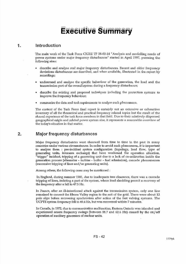
Executive Summary
8/12/2019 09 Frequency Stab
http://slidepdf.com/reader/full/09-frequency-stab 44/49
FS - 431539pk
8/12/2019 09 Frequency Stab
http://slidepdf.com/reader/full/09-frequency-stab 45/49
FS - 441539pk
8/12/2019 09 Frequency Stab
http://slidepdf.com/reader/full/09-frequency-stab 46/49
FS - 451539pk
8/12/2019 09 Frequency Stab
http://slidepdf.com/reader/full/09-frequency-stab 47/49
FS - 461539pk
8/12/2019 09 Frequency Stab
http://slidepdf.com/reader/full/09-frequency-stab 48/49
FS - 471539pk
8/12/2019 09 Frequency Stab
http://slidepdf.com/reader/full/09-frequency-stab 49/49