0912 et coolingtoweralignment
TRANSCRIPT
8/2/2019 0912 ET CoolingTowerAlignment
http://slidepdf.com/reader/full/0912-et-coolingtoweralignment 1/310 n eNerGY-TECH.com December 2009
FeATUreS
When an HVAC technician is called out to perform
a shaft alignment on a cooling tower fan, it is always anadventure, and seldom a pleasant one. Numerous challeng-
es are involved, not the least of which include the distance
to be spanned, vibration from surrounding fans, hazardous
wet conditions, and obstructions, both to line of sight as
well as mobility. Using dial indicators in the “face-face-
distance” method, the job might take many hours, and
much longer if soft foot is found and must be corrected.
The following application in a large hospital is illustra-
tive of a number of frequently encountered problems that
must be overcome, and how they were handled with a laser
alignment system.
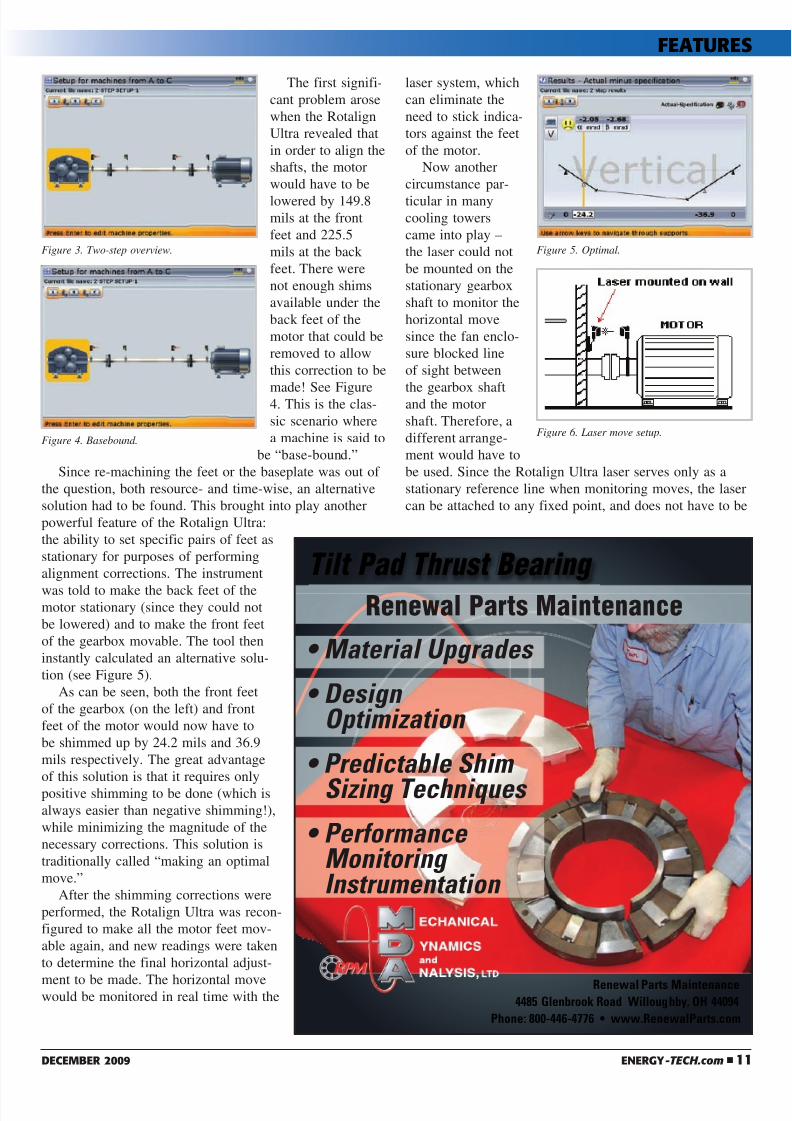
The cooling tower in question has a 12’ Marley fan
whose gearbox is coupled to a Baldor 40 H.P. 1775 rpm
motor via a 60˝ jackshaft with single flex plane couplings
at each end. The fan enclosure consists of a fiberglass shell
constructed around a wooden framework, located outside.
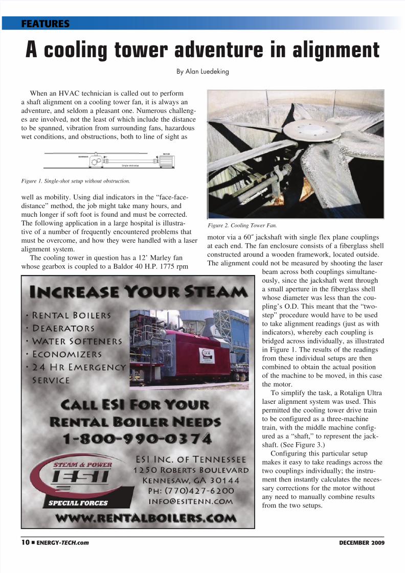
The alignment could not be measured by shooting the laser
beam across both couplings simultane-
ously, since the jackshaft went through
a small aperture in the fiberglass shell
whose diameter was less than the cou-
pling’s O.D. This meant that the “two-
step” procedure would have to be used
to take alignment readings (just as with
indicators), whereby each coupling is
bridged across individually, as illustrated
in Figure 1. The results of the readings
from these individual setups are then
combined to obtain the actual position
of the machine to be moved, in this case
the motor.
To simplify the task, a Rotalign Ultra
laser alignment system was used. Thispermitted the cooling tower drive train
to be configured as a three-machine
train, with the middle machine config-
ured as a “shaft,” to represent the jack-
shaft. (See Figure 3.)
Configuring this particular setup
makes it easy to take readings across the
two couplings individually; the instru-
ment then instantly calculates the neces-
sary corrections for the motor without
any need to manually combine results
from the two setups.
A cooling tower adventure in alignmentBy Alan Luedeking
Figure 1. Single-shot setup without obstruction.
Figure 2. Cooling Tower Fan.
8/2/2019 0912 ET CoolingTowerAlignment
http://slidepdf.com/reader/full/0912-et-coolingtoweralignment 2/3
8/2/2019 0912 ET CoolingTowerAlignment
http://slidepdf.com/reader/full/0912-et-coolingtoweralignment 3/3
12 n eNerGY-TECH.com December 2009
mounted on the sta-
tionary machine’s
shaft. This meant
that the laser could
be attached to a
fixed location on
the motor side of the fan enclosure.
In this case, a steel
angle-iron attached
to the wooden brac-
ing on the outside of
the fiberglass fan enclosure (on the motor side), provided
an ideal mounting location. The laser was mounted to this
angle iron using magnetic brackets. See an illustration of
this in Figure 6. With this convenient solution, no dial
indicators would need to be mounted against the feet of
the motor to control the motor’s move, and furthermore,
this laser setup also permits checking for soft foot on the
motor. The soft foot check and corrections were performed
after the rough alignment but prior to the final alignment.
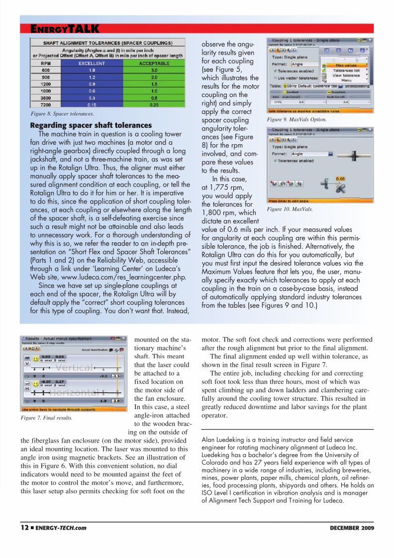
The final alignment ended up well within tolerance, as
shown in the final result screen in Figure 7.
The entire job, including checking for and correcting
soft foot took less than three hours, most of which was
spent climbing up and down ladders and clambering care-fully around the cooling tower structure. This resulted in
greatly reduced downtime and labor savings for the plant
operator.
Alan Luedeking is a training instructor and field serviceengineer for rotating machinery alignment at Ludeca Inc.Luedeking has a bachelor’s degree from the University ofColorado and has 27 years field experience with all types ofmachinery in a wide range of industries, including breweries,mines, power plants, paper mills, chemical plants, oil refiner-
ies, food processing plants, shipyards and others. He holds anISO Level I certification in vibration analysis and is managerof Alignment Tech Support and Training for Ludeca.
rgading spa shaft tolansThe machine train in question is a cooling tower
fan drive with just two machines (a motor and aright-angle gearbox) directly coupled through a longjackshaft, and not a three-machine train, as was setup in the Rotalign Ultra. Thus, the aligner must eithermanually apply spacer shaft tolerances to the mea-sured alignment condition at each coupling, or tell the
Rotalign Ultra to do it for him or her. It is imperativeto do this, since the application of short coupling toler-ances, at each coupling or elsewhere along the lengthof the spacer shaft, is a self-defeating exercise sincesuch a result might not be attainable and also leadsto unnecessary work. For a thorough understanding ofwhy this is so, we refer the reader to an in-depth pre-sentation on “Short Flex and Spacer Shaft Tolerances”(Parts 1 and 2) on the Reliability Web, accessiblethrough a link under ‘Learning Center’ on Ludeca’sWeb site, www.ludeca.com/res_learningcenter.php.
Since we have set up single-plane couplings at
each end of the spacer, the Rotalign Ultra will bydefault apply the “correct” short coupling tolerancesfor this type of coupling. You don’t want that. Instead,
observe the angu-larity results givenfor each coupling(see Figure 5,which illustrates theresults for the motor
coupling on theright) and simplyapply the correctspacer couplingangularity toler-ances (see Figure8) for the rpminvolved, and com-pare these valuesto the results.
In this case,at 1,775 rpm,
you would applythe tolerances for1,800 rpm, whichdictate an excellentvalue of 0.6 mils per inch. If your measured valuesfor angularity at each coupling are within this permis-sible tolerance, the job is finished. Alternatively, theRotalign Ultra can do this for you automatically, but you must first input the desired tolerance values via theMaximum Values feature that lets you, the user, manu-ally specify exactly which tolerances to apply at eachcoupling in the train on a case-by-case basis, insteadof automatically applying standard industry tolerancesfrom the tables (see Figures 9 and 10.)
EnErgy TALK
Figure 8. Spacer tolerances.
Figure 7. Final results.
Figure 9. MaxVals Option.
Figure 10. MaxVals.