1 - 1 use cases tutorial dennis mancl lucent technologies / software technology center september...
Post on 21-Dec-2015
216 views
TRANSCRIPT

1 - 1
Use Cases Tutorial
Dennis Mancl
Lucent Technologies / Software Technology Center
September 2003

1 - 2
Software models
• Software models are diagrams, text descriptions of components, pseudocode, and prototype code– models provide a partial description of the software system to be built
– models are an important part of the communication process
– models help to make vague notions and statements more precise
• This tutorial will present an important “object oriented” modeling notation: Use cases
• There are other more “formal” object oriented modeling notations, for example, some of the diagrams that are part of the Unified Modeling Language notation:– Class diagrams, State diagrams, Collaboration diagrams, etc.

1 - 3
Why build models?
• To organize the work– Building software is a time-consuming and complex operation
– Good quality software can have a long lifetime
• To improve communication among team members– Software is very labor-intensive: many people play a part in the
construction of a software product
– Ordinary text documentation is inherently imprecise and ambiguous
• To aid in the “thinking process”– In most software development projects, the actual form of the “thing to be
built” is initially very vague
– Iterative and incremental development will focus on changes to the models - it is easier to “rebuild the model” than to “rebuild the system”
1 - 4
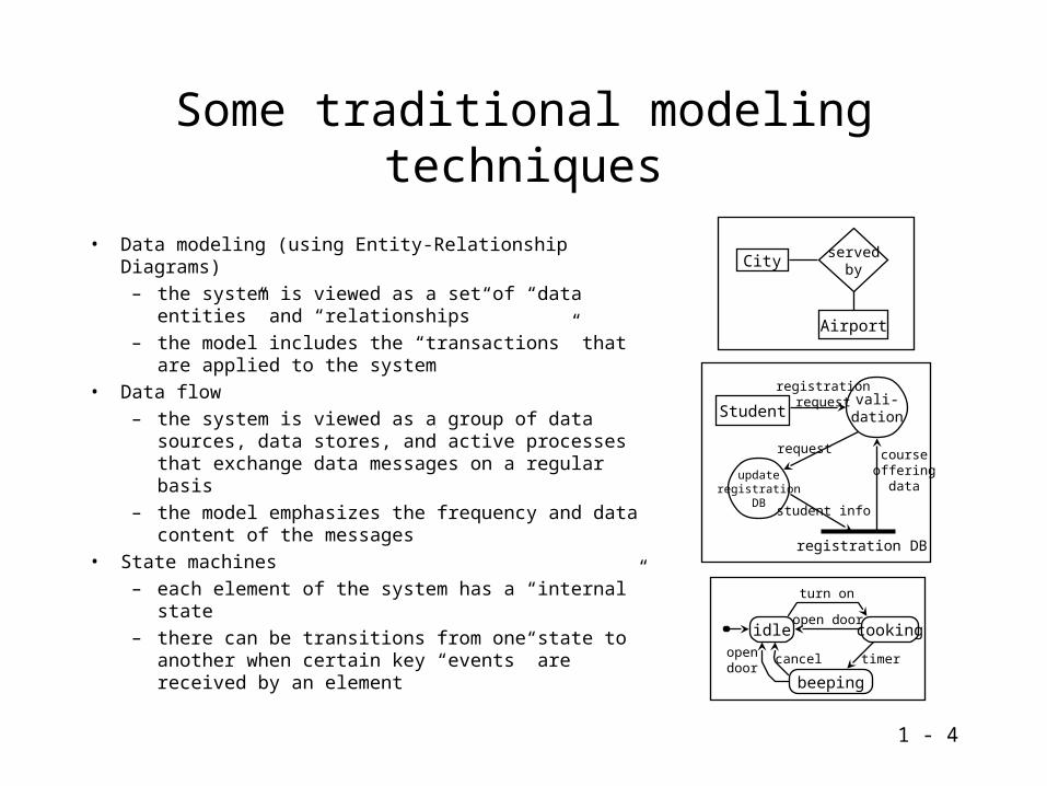
Some traditional modeling techniques
• Data modeling (using Entity-Relationship Diagrams)– the system is viewed as a set of “data entities” and
“relationships”– the model includes the “transactions” that are applied
to the system• Data flow
– the system is viewed as a group of data sources, data stores, and active processes that exchange data messages on a regular basis
– the model emphasizes the frequency and data content of the messages
• State machines– each element of the system has a “internal” state– there can be transitions from one state to another
when certain key “events” are received by an element
courseoffering
data
vali-dationStudent
registrationrequest
updateregistration
DB
request
registration DB
student info
Airport
servedbyCity
idle
beeping
cooking
turn on
open door
opendoor
cancel timer

1 - 5
Use cases and CRC cards
• Use cases are written to describe the external view of a system– Use cases may describe the high-level physical architecture of a system
– but they leave out most of the details about “how” the system will perform most of its functions
• CRC cards are created to describe the high-level classes of a system: they describe the first internal view of a system– CRC cards are another “informal” modeling technique that is widely used
for the initial “brainstorming” process
– CRC cards attempt to identify the high-level classes by describing their behavior and principal interactions
– For more information on CRC cards, see Nancy Wilkinson’s book Using CRC Cards (SIGS Books, 1995)
1 - 6
What is a use case?
• A group of scenarios that describe the goals and activities of the system and its users– many of the system-level requirements can be documented as use cases
– use cases specify contracts that the system needs to support
• A use case is an abstraction: it usually describes a bunch of related scenarios
• Use cases are often very general, so their scenarios are initially written with very little design-level detail
• When do you create use cases?– Use cases are documented in a semi-formal manner during the process of
creating the initial system requirements
– Use cases may be maintained over the lifetime of a software project

1 - 7
Using use cases todescribe requirements
• Use cases can show the sets of possible interactions between the system and the people who use it
• Use cases can also show interactions between computer systems
• Use cases can also be used at the subsystem level (to show interactions between subsystems)
register
deleteoffering
create newcourse
My systemStudent
Administrator
Instructor
Example use case diagram
actors use cases

1 - 8
Actors
• An actor is an entity that is outside of the system
• Actors will interact with the system:– an actor will often request the system to perform some actions on behalf
of the actor
– an actor may also receive responses from the system
• An actor plays a “role” in the use of the system– the name given to an actor is usually the “role name”: for example, an
actor who is a Person will usually be called a User, Operator, Administrator, or something like that
– each role might be treated as a different actor in the use cases

1 - 9
Identifying actors
• An Automated Teller Machine (ATM) permits customers to withdraw money from their accounts, make deposits, and check their account balances. The ATM machine communicates with a computer system in the bank’s central office to validate passwords and account information. The ATM is serviced on a regular basis by bank employees, to collect deposit envelopes and to load in more cash and receipt paper.
• Question: who are the actors in this system?–
–
–
–

1 - 10
Communication between actorsand the system
• In each use case, a “primary actor” starts things off: that actor initiates an interaction with the system
• The system will then respond to messages and might send messages of its own to other actors
• In a use case, the primary actor is trying to achieve a specific goal:– the use case consists of all the possible interactions that take place in the
attempt to reach the goal
– there may be many scenarios in a use case - each scenario shows an alternative “course” that is based on the success or failure of some of the intermediate steps
– the goal might not be reached (because of some of the failures)

1 - 11
Goals
• A goal is a result that one of the actors wants to achieve
• Example goals:– An administrator wants to add a new user to the system
– A pilot wants to land a plane
– A customer wants to file a claim on an insurance policy
– A service person wants to file a trouble report

1 - 12
Scenarios
• A scenario is a little story– it is an outline of some expected
sequence of events
• A scenario is used to convey the fundamentals of “how things work”
• It usually includes at least one actor
• Each actor can make requests of the system or respond to system activity
That will be $7.40.
Here is $10.
Thanks. Here are your stamps and your change.
Yes.
OK. Will that be all?
I would like a book of stamps, please.

1 - 13
Showing a scenario in text format
• A scenario can be written as a series of sentences:– each sentence shows one step of the scenario– each step needs to explain
• who does the operation• what operation is performed• when the operation is performed• are there any side conditions?
– one important thing that is not included in the description of each step of a scenario: how the operation is performed (this is left for the design phase)
• Important style points:– each step in the scenario must have a subject (either the system or an
actor is performing the step)– no passive or impersonal voice allowed (e.g., “the results are displayed”)

1 - 14
Example of a text format scenario
Customer buys a single item:1. Customer asks for an item2. Postal clerk acknowledges customer request, checks if the
requested item is available3. Postal clerk asks the Customer if there will be anything else in this
transaction4. Customer indicates that they don’t want anything else5. Postal clerk determines the price of the requested items and tells
the customer6. Customer pays7. Postal clerk gives the Customer the items and change
• Note: this is not yet a use case, just a single scenario.

1 - 15
Showing a scenario in graphical form
• Scenarios can be shown in a standard graphical notation – this notation has many different names– Sequence diagram, Event trace diagram, Interaction diagram, Fence post
diagram
Acknowledge request
Postal clerkCustomer
No
Anything else?
Respond with price
Give item and change
Give money
Ask for item

1 - 16
Writing a use case
Step 1: Pick one of the potential goals of one of the actors
Step 2: Write down the preconditions for that goal
Step 3: Write the “sunny-day” scenario for the interaction between actors and system
Step 4: Identify the possible failures at each step - think about the alternative scenarios that might result
Step 5: For the main failure situations, either create entire scenarios or create extensions of the main scenario
optional step: Find common chunks that occur in several scenarios that can be factored out to make the scenarios simpler

1 - 17
Creating a simple scenario
• Draw a sequence diagram for one of the scenarios in the ATM system. One prominent use case in this system is “customer performs an ATM transaction,” and one scenario in that use case is “customer withdraws money”. Assume we are in the sunny-day scenario.
Customer ATM
1. Customer inserts card???

1 - 18
Primary Actors: Technician, UnitPrecondition: RCS in service, LAPD-Link up, Unit equippedFrequency: on demand, autonomousSuccessful Post-condition: Alarm data sent sent to ECPFailed Post-condition: Trigger: Received Alarm Reporting and Alarm Q Request Message from ECP or OA/M
TI OAM RC
1. OA&M Receive Alarm Summary Request
Use Case # 47 Alarm Scan
2. Activate Alarm reporting at the RC
3. ACK
5. Receive Alarm Query response from RC6. Send Alarm message to ECP and ROP
7. Receive autonomous Alarm from RC
4. Send Alarm Query message to RC
8. Send Alarm message to ECP and ROP

1 - 19
Primary Actors: TI, HEH (OAM Autonomous)Precondition: EquippedFrequency: N/ASuccessful Post-condition: Radio is in ServiceFailed Post-condition: Radio is out of ServiceTrigger: RST TI command, or RCS Autonomous
TI OAM Unit
1: Request RST
3. Reset Unit
7. Acknowledge
Use Case #33 Restore Radio (CDL)
<PASSING DIAG USE CASE>
4. Poll Unit
5. Unit up
6. Configure Unit
block_trunks()if (CPBusy) { request handoffs() (for 5mins)}if (CPbusy) { if UCL { Kill_calls() } else { reject request; unblock; }}
CP/VCA
2: Block trunks if needed (see insert)

1 - 20
Another exampleUse case: SMI Client Unlocks Feature Goal: SMI Client wants to unlock a particular feature on one or more NEs.
Preconditions:• The NE is operational and is configured to communicate with the SMI Client.• A feature that is locked is installed on the NE. • The SMI client is connected to the SMI. • The SMI client knows the name and key information for the locked feature.
Success end condition: The feature is unlocked at the NE and the SMI Client has received the feature locking information for the specified feature.
Actors: SMI Client, NE
Main scenario:1. The SMI Client sends a message to the NE requesting a feature be unlocked. The message defines a feature key that must be correctly specified in order for the request to succeed.
2. The NE receives and processes the message. The message is determined to be a valid message.
3. The NE unlocks the feature using additional internal processing.
4. The NE sends a message to the SMI client that indicates that the feature was unlocked.
5. The SMI Client receives each message containing the feature locking information for the specified feature. SUCCESS
1 - 21
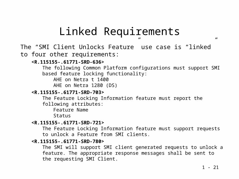
Linked RequirementsThe “SMI Client Unlocks Feature” use case is “linked” to four other requirements:
<R.115155-.61771-SRD-636> The following Common Platform configurations must support SMI based feature locking functionality:
AHE on Netra t 1400AHE on Netra 1280 (DS)
<R.115155-.61771-SRD-703> The Feature Locking Information feature must report the following attributes:
Feature Name Status
<R.115155-.61771-SRD-721>The Feature Locking Information feature must support requests to unlock a Feature from SMI clients.
<R.115155-.61771-SRD-780> The SMI will support SMI client generated requests to unlock a feature. The appropriate response messages shall be sent to the requesting SMI Client.

1 - 22
1 - 23

1 - 24

1 - 25
Making scenarios more elaborate
• There are three ways to create more elaborate scenarios:– Variations
– Extensions
– Chunks (subfunctions)

1 - 26
Variations
• A variation is a way to avoid “scenario explosion”
• A variation is a list of alternatives that is tied to a specific line of a scenario
• Each variation could turn into a lower-level scenario
• An example variation (for the post office scenario):1. Item is
a. stampsb. postage on an item that the customer
is mailingc. postage due on an item that the
customer is receivingd. post office box rentale. mugs, t-shirts, and other Postal
Service merchandise6. Payment is
a. ______________b. ______________c. ______________
Main scenario:
1. Customer asks for an item
2. Postal clerk acknowledges customer request, checks if the requested item is available
3. Postal clerk asks the Customer if there will be anything else in this transaction
4. Customer indicates that they don’t want anything else
5. Postal clerk determines the price of the requested items and tells the customer
6. Customer pays
7. Postal clerk gives the Customer the items and change
1 - 27
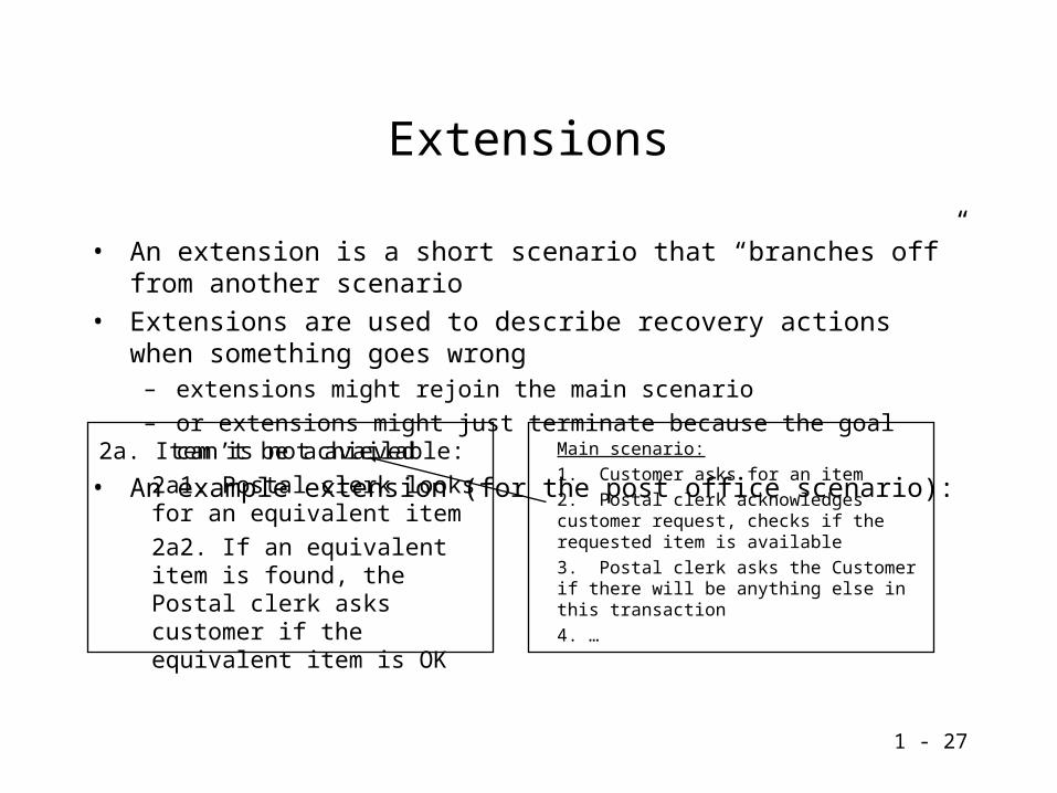
Extensions
• An extension is a short scenario that “branches off” from another scenario
• Extensions are used to describe recovery actions when something goes wrong– extensions might rejoin the main scenario
– or extensions might just terminate because the goal can’t be achieved
• An example extension (for the post office scenario):
2a. Item is not available:
2a1. Postal clerk looks for an equivalent item
2a2. If an equivalent item is found, the Postal clerk asks customer if the equivalent item is OK
Main scenario:
1. Customer asks for an item
2. Postal clerk acknowledges customer request, checks if the requested item is available
3. Postal clerk asks the Customer if there will be anything else in this transaction
4. …
1 - 28
Chunks
• A chunk is a “sub-scenario” - a sequence of messages that appears in several scenarios for one or more use cases.– A chunk is a scenario that addresses a specific subgoal
• for example: logging in, searching for a specific product, etc.
– They are the “subroutines” of the use case family
– They may express some common “user interface” sub-scenarios
– Alistair Cockburn calls them “subfunctions” (but we don’t want to think of them as associated with low-level code)
1 - 29
Break....
• After the break:– Simple use case template
– Definition of terms:• level of detail, level of
abstraction, level of scope
– A simple exercise

1 - 30
A simple format for a use case
Use case 1: Employee opens doorGoal: An Employee wants to unlock a door to pass from one room to
another.
Preconditions: The Employee has valid identification to open the door.
Success end condition: Employee has successfully opened the door.
Failed end condition: Door remains closed and the Security Guard on duty is notified.
Actors: Employee, Security Guard
Main scenario:
1. Employee’s identification and door identification is sent to system
2. Door is unlocked
3. Employee opens door, passes through the door, and recloses door, SUCCESS
Extensions:
2a. Employee’s identification is not valid
2a1. System notifies Security Guard, FAIL
opendoor
resetalarm
testalarm
Employee
SecurityGuard
RepairPerson
Office SecuritySystem

1 - 31
Levels of scope
Summary-level goals• “cloud-level”• might be things that
operate over hours, days, or weeks
User goals• “sea-level”• usually 2 to 20 minutes
Subfunctions• “under water”• not a real “user goal”:
these scenarios describe common suboperations
Add newservice
Add newservice
Find list ofservices
Find list ofservices
Upgrade allcustomers
Upgrade allcustomers

1 - 32
Use cases and requirements
• Use cases are requirements– a use case will specify the essential behavior that the system must deliver
• Use cases are usually about 1/3 of the total volume of requirements
• The use cases are supplemented by other kinds of requirements information– Business Rules: conditions, policies, and conventions
– Operational Profiles: how many scenarios
– Architectural Requirements: “-ilities” (reliability, usability, performance)
Business Rules
BR1. Each employee has a unique identification number.
BR2. Each “open-door” request is logged.
Architectural Requirements
AR1. Maximum time to process an “open-door” request is 15 seconds.
AR2. No more than 5 minutes downtime per year.
Operational Profiles
OP1. During the busy hour (8-9am), the system should be able to handle 500 “open-door” requests (UC1 sunny-day).
OP2. The “test alarm” use case will be executed every weekend.
1 - 33
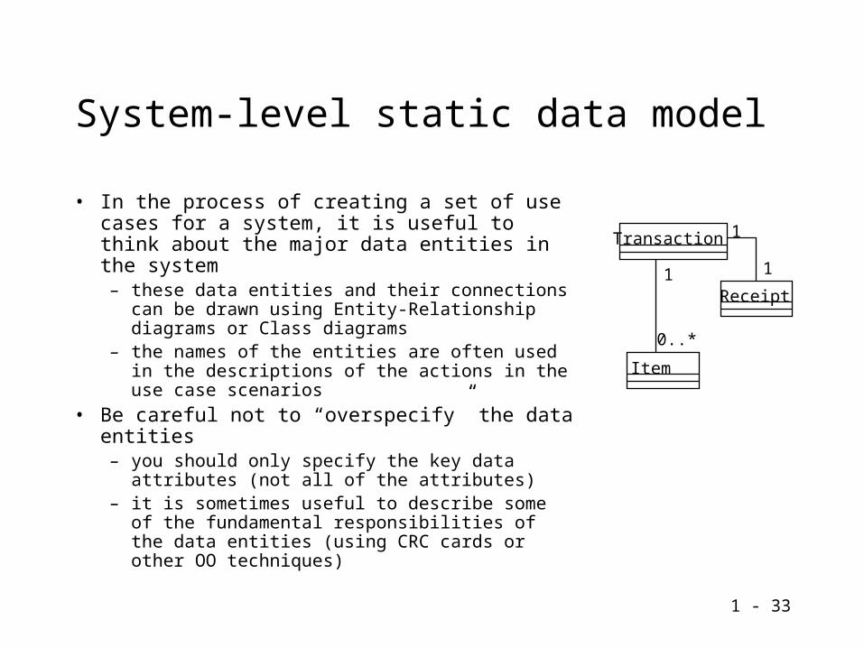
System-level static data model
• In the process of creating a set of use cases for a system, it is useful to think about the major data entities in the system– these data entities and their connections can be
drawn using Entity-Relationship diagrams or Class diagrams
– the names of the entities are often used in the descriptions of the actions in the use case scenarios
• Be careful not to “overspecify” the data entities– you should only specify the key data attributes
(not all of the attributes)– it is sometimes useful to describe some of the
fundamental responsibilities of the data entities (using CRC cards or other OO techniques)
Item
Transaction
Receipt
1
1
1
0..*

1 - 34
Scenarios and use cases indesign, coding, and test
• The use cases are a very useful form of requirements– they attempt to describe the externally visible behavior of the system
– they are concise enough for everyone to read (customers, developers, testers)
• Use cases can be kept under change control
• Design-level and code-level comments ought to refer to individual use cases, so that individual design decisions can be revisited when the use cases are changed
• System-level tests will use the information from use cases
1 - 35
Lottery system exercise
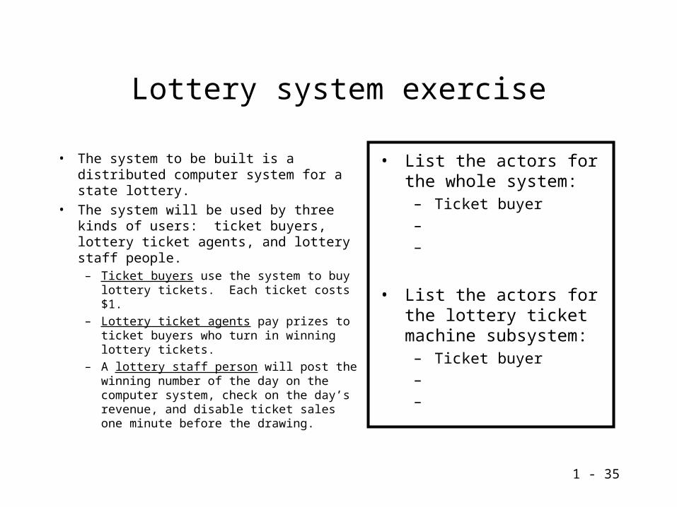
• The system to be built is a distributed computer system for a state lottery.
• The system will be used by three kinds of users: ticket buyers, lottery ticket agents, and lottery staff people.
– Ticket buyers use the system to buy lottery tickets. Each ticket costs $1.
– Lottery ticket agents pay prizes to ticket buyers who turn in winning lottery tickets.
– A lottery staff person will post the winning number of the day on the computer system, check on the day’s revenue, and disable ticket sales one minute before the drawing.
• List the actors for the whole system:
– Ticket buyer
–
–
• List the actors for the lottery ticket machine subsystem:
– Ticket buyer
–
–

1 - 36
A lottery system use case
• Use case for the “ticket buyer buys a ticket” situation (assume that we are considering the whole system and not just the lottery ticket machine subsystem):
Use case name:Ticket buyer buys a ticketActors: (a list of all the actors involved in this use case) ????Authors of this use case: meSummary:
Preconditions: (what has to be true before this use case can be initiated?) ????Frequency: (how often will this use case happen? – once per week, once per hour, …) ????Description: (in words or as one or more sequence diagrams – use more pages if needed) 1. 2.
Exceptions, Variations, Extensions, and Chunks:

1 - 37
Sample list of actors
• Actors for the whole system– Ticket buyer
– Lottery ticket agent
– Lottery staff person
• Actors for the ticket machine subsystem– Ticket buyer
– Central computer
– Machine service person
1 - 38
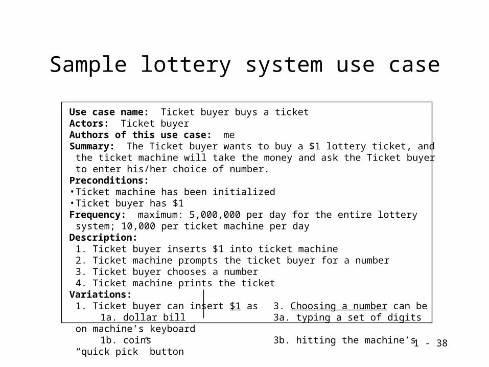
Sample lottery system use case
Use case name: Ticket buyer buys a ticketActors: Ticket buyerAuthors of this use case: meSummary: The Ticket buyer wants to buy a $1 lottery ticket, and the ticket machine will take
the money and ask the Ticket buyer to enter his/her choice of number.Preconditions: • Ticket machine has been initialized• Ticket buyer has $1Frequency: maximum: 5,000,000 per day for the entire lottery system; 10,000 per ticket
machine per dayDescription:
1. Ticket buyer inserts $1 into ticket machine2. Ticket machine prompts the ticket buyer for a number3. Ticket buyer chooses a number4. Ticket machine prints the ticket
Variations:1. Ticket buyer can insert $1 as 3. Choosing a number can be
1a. dollar bill 3a. typing a set of digits on machine’s keyboard1b. coins 3b. hitting the machine’s “quick pick” button
1 - 39
Summary
• This tutorial discussed use cases– it is a notation that is useful for recording system requirements
– CRC cards (useful for brainstorming an initial object-oriented model)
• Use cases are an “external” model of the system– they describe the interactions between actors (entities that are outside of
the system) and the system itself
– they can be documented using text or pictures
– each use case usually corresponds to multiple related scenarios

1 - 40
Break....
• After the break:– Use case pitfalls
– Doing “reviews” of use cases

1 - 41
Use Case Pitfalls
• Over-reliance on a drawing tool– don’t need to draw Sequence Diagrams / MSCs for most requirements-
level scenarios – “structured text” is fine– hand-drawn scenarios in Powerpoint are difficult to maintain– really hard to show branch scenarios and looping
• Missing actor descriptions– some folks jump into writing scenarios before describing the participants
in the scenarios– there can be a lot of confusion about the system boundaries– actor descriptions help find missing goals
• Too much detail in the scenarios– scenarios should describe what rather than how– to describe “how” – jump out of use case notation, use design
diagramming notations instead
1 - 42
Use Case Reviews
• Who is involved in a use case review?– systems engineers – the authors of the use case package
– architects – to get an overall picture of system communcation and performance
– developers – to get information about which requirements need to be implemented in a flexible way
– testers – to check that the actions and conditions specified in the use cases are concrete and testable

1 - 43
Should a use case review include “customers”?
• Yes! Early use case review for customers– Review of the actor model – look for missing actors– Review of use case titles – look for missing goals– A very superficial review of sunny-day scenarios: customers usually don’t
care about “how” the use case reaches its goal– A brainstorming session about failure cases (without getting into the
details of failure scenarios): customers often know which are the most important failures to “detect”
• More detailed review for the project (without customers)– Another review just for systems engineers, architects, developers, and
testers– Customers won’t participate in this review – it might include analysis of
implementation tactics, testing strategy, and “prioritization” of the use cases

1 - 44
Preparing for a review
• It isn’t necessary for each reviewer to read all of the use cases• Some simple review strategies – each of these techniques will raise
some issues– pretend to be one of the actors when reading the scenarios– count the number of times each use case will be executed by the system in
the typical hour– try to write key test scenarios from the use cases– starting with a specific use case, create a “storyboard” for the user
interface– use several use cases as the input to a CRC card brainstorming exercise
• Each individual reviewer can bring a list of issues to the review– missing goals, test information gaps, ideas for improving the system’s
performance and usability

1 - 45
Things to look for in a review
• “Think” like an architect or a tester• Preconditions should be as precise as possible
– can you easily test if the preconditions are satisfied?
• Each step in the scenarios should be “observable”– there is some way to check that the action specified in the step actually
took place– this will be important later in testing
• Performance information should be accurate– performance constraints can be documented in each step as a side
condition, or you can have an end-to-end performance goal for the entire scenario
– architects may use the “frequency” information to build a performance model

1 - 46
Failure scenarios
• It is impossible to enumerate all of the possible failures• It is useful to describe two kinds of failures:
– The default “abandon the goal” catastrophic failure – this can be a branch scenario that explains how to clean up and back out any partially completed work
– Some “recovery scenarios” that cause the system to ask the actors for different information
• Example of “abandon the goal” failure:– ATM can’t dispense cash: 1. undo the withdrawal from the account, 2. return card
to the customer, 3. give customer visual and/or printed feedback of the cancellation action
• Proper cleanup on failure:– note that if the system fails to allocate all of the resources the actor needs, then all
resources reserved on the behalf of the actor’s request will be released– the postcondition should be “the system’s state is as close as possible to the initial
state before the request”

1 - 47
Results of a use case review
• Add missing details to a use case model– define new use cases and actors – include accurate summary information
– add new failure scenarios
– fill in missing scenario steps
– make more links to requirements outside of the use case model (such as user interface standards, system constraints, -ilities)
• Restructure use case information– make use case scenarios more abstract – push the technical details into the
design documentation
• Throw out unnecessary use cases– in some cases, combine with similar use cases
– eliminate use cases that are outside the system scope

1 - 48
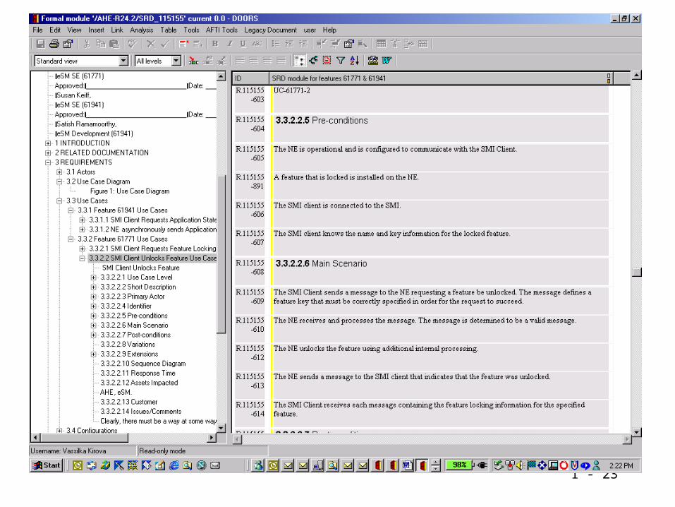
Using tools
• Use cases are really “low-tech” – you don’t need any technology at all to identify the actors and draw some scenarios
• Some technology alternatives:– use an MS-Word document template– use a requirements repository tool (Telelogic DOORS, Rational
RequisitePro)– use a modeling tool that can represent scenarios (Rational Rose, Telelogic
TAU)
• Use tools to do some minor automation– import scenarios into test management tool (DOORS TMS)– elaborate the test scenarios– create links from the test cases back to the use case scenarios within a use
case– if a use case is changed, you know which test cases need to be revisited

1 - 49
Vocabulary in this course
• use case: collection of scenarios related to a goal
• goal: what the actor is trying to accomplish when using the system (this might succeed or fail)
• scenario: a sequence of interactions
• sunny-day scenario: a scenario where everything works
• failure scenario: a scenario that explains what happens when something goes wrong
• variation: a set of choices for a single scenario step
• extension: a branch scenario that starts with an extension condition
• actor: a person or system outside of the system under development
• precondition: one of the conditions that must be true when a scenario of the use case is triggered
• chunk or subfunction: a set of scenario steps that are repeated in several different use cases
• business rule: one of the rules that describes how the business is run
• operational profile: description of which use cases will be run at the same time

1 - 50
Summary
• This mini-course has been an overview of use case terminology and process– Use cases are scenario-based documents that describe the
functional requirements of a system
– Use cases contain both “sunny-day” and failure scenarios
– Other “plain-old text requirements” can be linked to the use cases
• Useful books:– Writing Effective Use Cases by Alistair Cockburn
– Patterns for Effective Use Cases by Steve Adolph and Paul Bramble
– Use Case Modeling by Kurt Bittner and Ian Spence