1 introductionrisedr.tongji.edu.cn/7th_kwang-hua_forum/files/parallel... · 2017-01-06 · 1...
TRANSCRIPT


1 Introduction● Concrete filled steel tubular (CFST) : high strength, fire resistance, favourable ductility
and large energy dissipation capacity.● Various connection alternatives to CFST
sections have been explored. additional fittings, through-bolt connections, internal
or external diaphragm plates etc.● Use of these connection methods has not
always been convenient in construction practice.
● Bolt installation from oneside of the connection only without the need for access within HSS column.

1 Introduction● Static behaviour of blind bolted joints to
HSS or CFST columns: Korol et al. (1993), France et al. (1999a; 1999b;
1999c)), Loh et al. (2006), Yao et al. (2008), Wang et al. (2009a), and Lee et al. (2010).
● Seismic behaviour of blind bolted joints to HSS or CFST columns:
Mourad et al. (1995), Gardner and Goldsworthy (2005), Wang et al. (2009b), Elghazouli et al. (2009), and Mirza and Uy (2011).
● Need for an extensive experimental and analytical study the behavior of blind bolted joints and frames to CFST columns.
2 Blind Fasteners
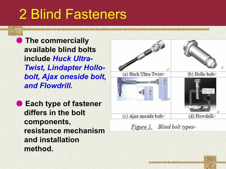
● The commercially available blind bolts include Huck Ultra-Twist, Lindapter Hollo-bolt, Ajax oneside bolt, and Flowdrill.
● Each type of fastener differs in the bolt components, resistance mechanism and installation method.

2 Blind fastener advantages ● high tensile and shear strengths, potential used in
tension applications; ● uniform high clamping force; ● aseismic resistance and excellent ductility; ● simple installation and reduced labour requirements; ● good architectural appearance;● easily be installed by unskilled technicians using
potable equipments.

3.1 Joint Test Specimens
● Sixteen end plate joints to CFST columns with blind bolts were tested under monotonic or cyclic loading.
● The test parameters included the column section type, the end plate thickness, the end plate type, and the load type.

3.1 Joint Test Specimens

3.2 Static Test Results
● For flush end plate joints, failure modes included :
(1) deformation of the end plate; (2) outward deformation of the column flange; (3) anchorages of the tensile bolts; (4) crushing of core concrete due to the larger connection rotation; and (5) cracks in the corner of the square steel tubes around first row of tensile bolts.
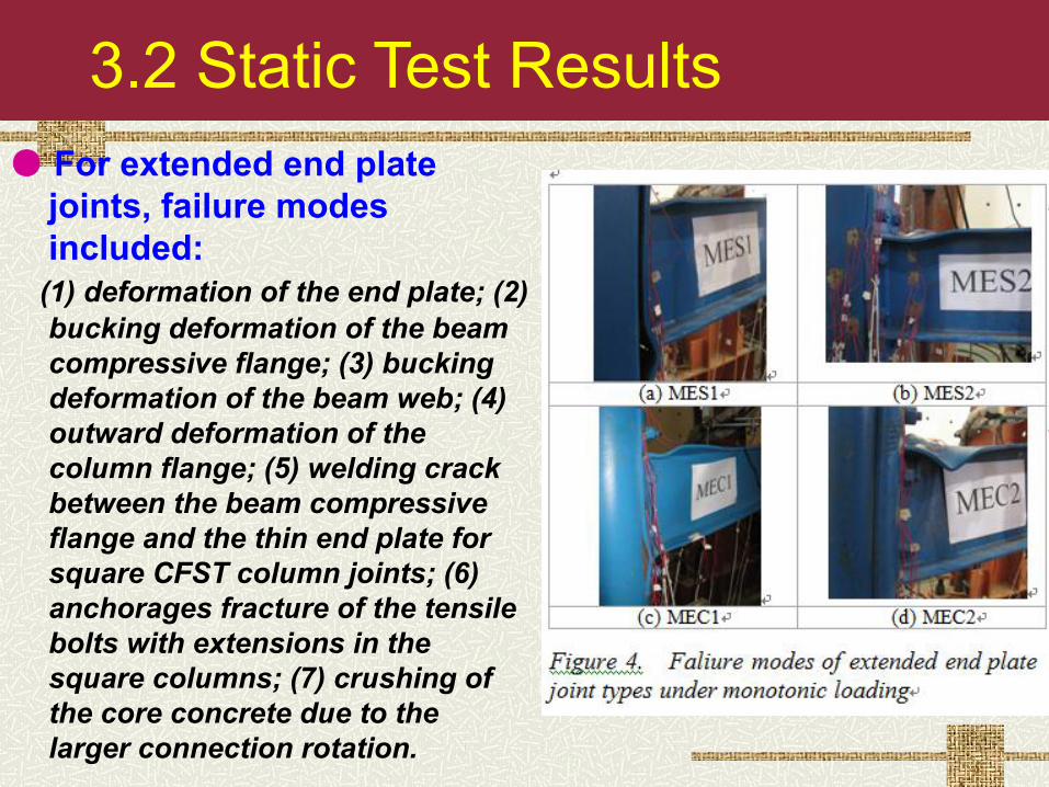
3.2 Static Test Results ● For extended end plate
joints, failure modes included:
(1) deformation of the end plate; (2) bucking deformation of the beam compressive flange; (3) bucking deformation of the beam web; (4) outward deformation of the column flange; (5) welding crack between the beam compressive flange and the thin end plate for square CFST column joints; (6) anchorages fracture of the tensile bolts with extensions in the square columns; (7) crushing of the core concrete due to the larger connection rotation.

3.2 Static Test Results
● The static test results showed the blind bolted end plate joints exhibited favorable strength, stiffness and deformation performance for use in a moment resisting frame.
(a) Flush end plate connections (b) Extended end plate connections
Figure 5. Moment-rotation curves of test specimens

3.3 Cyclic Test Results
(a) Flush end plate connections
Figure 6. Moment-rotation hysteretic curves of test specimens

3.3 Cyclic Test Results
(b) Extended end plate connections
Figure 6. Moment-rotation hysteretic curves of test specimens

3.2 Cyclic Test Results
● The end plate joints to circular or square CFST columns with blind bolts exhibited excellent seismic behaviour.
● Under cyclic loading, all specimens displayed large rotation ductility capacities, and the failure modes were similar to those under monotonic loads.
● The effects of cyclic loading on the joint performance were obvious, especially in load bearing and stiffness of the connections.

3.2 Cyclic Test Results● Presently it is lack of the detailed ductility regulation
for the CFST building structures. ● For flush end plate joint types, the displacement
ductility coefficient μ=5.08-6.05, the elastic yielding angular ductility coefficient y=(2.704.52)[e], and the elastic-plastic angular ductility coefficient u=(3.18-5.17)[p].
● For extended end plate joint types, the displacement ductility coefficient μ=3.25-7.65, the elastic yielding angular ductility coefficient y =(2.98-4.59)[e], and the elastic-plastic angular ductility coefficient u =(2.86-4.77)[p].
● blind bolted end plate joints to CFST columns displayed better ductility and satisfied the requirement of the structural seismic design.

4. Finite element analysis model
End plate Steel beam Blind bolt Steel tube Core concrete

4. Finite element analysis model
Specimen CJM1
Tested Predicted
Tested PredictedSpecimen MES2
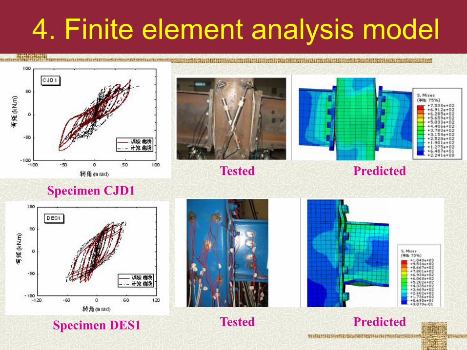
4. Finite element analysis model
Specimen CJD1Tested Predicted
Tested PredictedSpecimen DES1

5.1 Moment-rotation relationship model
rppc ]1[ pc
rrpi
KeMM MCKK
A four parameter exponential model to predict the nonlinear connection response that reflects the typical behaviour
where Ki is the initial elastic stiffness; Kp is the post elastic stiffness; Mpc is the plastic moment capacity of the connection; C is rate of decay parameter; θr is the connection rotation.

5.1 Moment-rotation relationship model
Moment capacity of joint

5.1 Moment-rotation relationship model
Initial stiffness of joint

5.2 Construction detail
Local thickening of tube wall in panel zone

5.2 Construction detail
Anchorage strengthening of blind bolts

6.1 Frame Test Specimens
● Two semi-rigid square CFST composite frames were tested under cyclic loading.
● The test parameters included the end plate type and the load type.

6.2 Frame Test Results
● For blind bolted frames, failure occurred :
(1) end plate deformation; (2) bucking deformation of the beam compressive flange; (3) bucking deformation of the beam web; (4) outward deformation of the column flange; (5) welding crack between the beam compressive flange and the thin end plate for square CFST column joints;

6.2 Frame Test Results
● For blind bolted frames, failure occurred :
(6) anchorages fracture of the tensile bolts with extensions in the square columns; (7) crushing of the concrete core due to the larger connection rotation.

6.2 Frame Test Results ● Hysteretic Behavior
● The test results showed that the load versus displacement hysteretic curves for the semi-rigid square CFST frames were robust.

7 Frame FE Analysis ● Material Constitutive Model

7 Frame FE Analysis
● FEA results
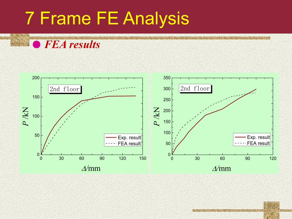
7 Frame FE Analysis ● FEA results
0 30 60 90 120 1500
50
100
150
200
P /k
N
/mm
Exp. result FEA result
2nd floor
0 30 60 90 1200
50
100
150
200
250
300
350
2nd floor
P /k
N/mm
Exp. result FEA result

8 Conclusions Joint research results:● The blind bolted end plate joint to CFST columns
exhibits favorable strength and stiffness, and its rotation capacity satisfies the ductility requirement for earthquake resistance in seismic region.
● A nonliear FEA model of the joint types under monotonic or cyclic loading was developed to investigate the joint response.
● A simplified component-based model was proposed to examine the stiffness characteristics of the joint types.
● Simplified design approaches proposed enable improvement to the design of blind bolted joints to be applied in engineering practice.

8 Conclusions
Frame research results:● The semi-rigid square CFST frames exhibit large
hysteretic loops, good ductility, and excellent energy dissipation capacity.
● On the whole, the FE analysis results agreed well with the experiment results. It can be used to analysis and design for the typed composite frames.
