design and behavior of bolted joints - nutek-us.comnutek-us.com/qitt06 - bolted joints.pdf ·...
TRANSCRIPT
Design and Behavior of Bolted Joints

Section 0 Introduction and Content Page ii
Nutek, Inc. All Rights Reserved. www.nutek-us.com Design and Behavior of Bolted Joints Version: 0602
Design and Behavior of Bolted Joints Course Description:
Modern buildings, vehicles, machinery, and physical products of all sizes and shapes are put together by joining smaller components with another. A vast majority among these is assembled with fasteners, as they need to come apart for potential repair, replacement, or maintenance. Simply put, a fastener is a screw, nut, bolt or stud with external or internal threads. Although, there are numerous types of fasteners used in commerce, understanding the design and behavior of a threaded joint serves to comprehend the basic principles applicable to all fasteners.
Why should you study fasteners? Approximately 200 billion fasteners are utilized by the industry each year. Many such fasteners play important roles in transportation, safety and comfort of our modern life. A typical automobile, for example, uses about 4000 nuts and bolts. Because a few of them once in a while would come loose, over half of the warranty dollars for the same automobile can be related to fasteners.
In spite of its immense importance, bolted joints are not well understood. Part of the theoretical and empirical relations work fairly well in the design phase. Unfortunately, in installations, that is, in the assembly process, the behavior of a bolted joint depends on a large number of variables that are difficult or impossible to predict and control. Obtaining the desired load and configuration is subjected to a high degree of uncertainty that calls for a greater need for understanding of the operating principles involved. Thus the specialists who design and assemble things which must not fail; airplanes, nuclear reactor, engine connecting rods, engine block heads, all kinds of safety related items in an automobile, etc., must learn all there is to known about the behavior of the joints concerned.
This short session is intended for practicing design and manufacturing professionals who are involved in assembly of electro-mechanical hardware components of any size and shapes with fasteners of all kinds. Attendees are expected to participate in hands-on group exercises and solve a number of problems on theoretical principles discussed in the class (Attendees are required to bring a scientific calculator). Learning Objectives (bullet form): Upon completion of this seminar, you will learn how to: - Calculate forces in the fasteners - Establish what torque to specify - How to increase functional life of a joint - Analyze joints and its failure mechanism - Achieve better control of bolt tension and applied torque in the assembly operations - Utilize torque application machines more effectively - Reduce fastener related warranty and rework costs

Section 0 Introduction and Content Page iii
Nutek, Inc. All Rights Reserved. www.nutek-us.com Design and Behavior of Bolted Joints Version: 0602
Instructor’s Background Ranjit K. Roy, Ph.D., P.E., PMP (Mechanical Engineering, president of NUTEK, INC.), is an internationally known consultant and trainer specializing in the Taguchi approach of quality improvement. Dr. Roy has achieved recognition for his down-to-earth style of teaching of the Taguchi experimental design technique to industrial practitioners. Dr. Roy began his career with The Burroughs Corporation following the completion of graduate studies in engineering at the University of Missouri-Rolla in 1972. He then worked for General Motors Corp. (1976-1987) assuming various engineering responsibilities, his last position being that of reliability manager. While at GM, he consulted on a large number of documented Taguchi case studies of significant cost savings. He is the author of the textbooks A Primer On The Taguchi Method - published by the Society of Manufacturing Engineers in Dearborn, Michigan, Design of Experiments Using the Taguchi Approach: 16 Steps to Product and Process Improvement published (January 2001) by John Wiley & Sons, New York, and of Qualitek-4 software for design and analysis of Taguchi experiments. Dr. Roy is a fellow of the American Society for Quality and an adjunct professor at Oakland University, Rochester, Michigan. Dr. Roy is listed in the Marquis Who’s Who in the world.

Section 0 Introduction and Content Page iv
Nutek, Inc. All Rights Reserved. www.nutek-us.com Design and Behavior of Bolted Joints Version: 0602
ABOUT THE COURSE Course Content Section - A Fundamental Principles and Supporting Theories
• Why Study Fasteners? • Basic Principles of BOLT Operation • English vs. Metric Units of Measurements • Physics of Stationery Bodies • Rigid Body in a State of Equilibrium • Bolt Load and Free Body Diagram (FBD) • Effect of Friction • Friction Forces on Inclined Plane • Principles of Conservation of Energy • General Stiffness Principles • Stress, Strain and Mechanical Properties • Properties of Engineering Materials • Equivalent Joint Stiffness • Effect Of Joint Relaxation On Preload • How To Minimize Relaxation • Thermal Effect On Bolt Tension • Joint Behavior And Geometry Under External Load
Section B Fasteners Design Strategies and Assembly Considerations
• Torque and Tension Relationship • The Short-Form of Torque vs. Tension Relation • Uncertainty in Assembly Caused By Variability in Nut factor (K) • Factors That Affect Tension Variability • Assembly Torque and Tension Behavior • Process Variation and Process Capabilities • Primary Influencing Factors Affecting Preload • Bolt Tightening Strategies • Three Strategies Commonly Used to Control Preload • Inspection of Installed Torque • Bolt And Thread Geometry • Bolt Identification • Torque, Angle, and Tension Measuring Devices • Torque Scatter Due To Tool • Standardized Torque and Tension Values

Section 0 Introduction and Content Page v
Nutek, Inc. All Rights Reserved. www.nutek-us.com Design and Behavior of Bolted Joints Version: 0602
• Bolted Joint Design Strategy • Joint Assembly and Behavior • Generalized Hooke’s Law • Mechanical Properties of Steel
Section – C Gasketed Joints for Leak Prevention
• Mechanical Behavior Of A Gasket • Effect Of Creep And Relaxation On Gasket Behavior • Example of Creep Relaxation • Factors that Affect Creep • Gasket Strenth - The P x T Factor • Leakage Behavior Of Gasket – m and y Factors • Gasket Selection • Simplistic Design & Assmebly Guidelines • Exercises
Gasketed Flanged Joint Design
• Objectives and Design Challenges • Types of Flanged Joints • Analysis of Flanged Joints – Simplified Model • Design Steps • Standards and Codes for Flanged Joints • Example Flange Joint Design • Exercise
Section – D Causes and Prevention of Bolt Failure
• Corrosion • Essential conditions for Corrosion • Chemistry of Corrosion • Strategies for Corrosion Reduction • Combating Corrosion • Common Types of Coating • Commercial Fastener Coatings • Causes Of Joint Failure • Mechanical Failure Modes of Bolted Joints • Prevention of Vibration Loosening • Mechanical Properties Of Typical Medium/Low
• Carbon And Case Hardened Steels
Section 0 Introduction and Content Page vi
Nutek, Inc. All Rights Reserved. www.nutek-us.com Design and Behavior of Bolted Joints Version: 0602
• Numbering Systems for Carbon and Alloy Steels • Load Magnification on Joints • Fatigue Failure • Reducing Fatigue Problems
Appendix
• Sources of Bolting Specifications • The Fastener Quality Act: Insignia Recordals • Glossary of Fastener and Bolted Joint Terms • References
Section – A
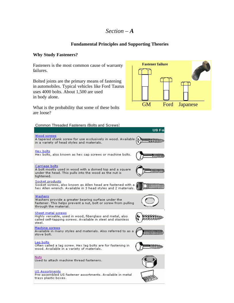
Fundamental Principles and Supporting Theories Why Study Fasteners? Fasteners is the most common cause of warranty failures. Bolted joints are the primary means of fastening in automobiles. Typical vehicles like Ford Taurus uses 4000 bolts. About 1,500 are used in body alone. What is the probability that some of these bolts are loose?
Fastener failure
GM Ford Japanese
Common Threaded Fasteners (Bolts and Screws)
Section A Fundamental Principles and Supporting Theories Page A - 2
Nutek, Inc. All Rights Reserved. www.nutek-us.com Design and Behavior of Bolted Joints Version: 0602
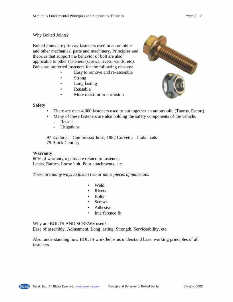
Why Bolted Joints? Bolted joints are primary fasteners used in automobile and other mechanical parts and machinery. Principles and theories that support the behavior of bolt are also applicable to other fasteners (screws, rivets, welds, etc). Bolts are preferred fasteners for the following reasons:
• Easy to remove and re-assemble • Strong • Long lasting • Reusable • More resistant to corrosion
Safety
• There are over 4,000 fasteners used to put together an automobile (Taurus, Escort). • Many of these fasteners are also holding the safety components of the vehicle.
- Recalls - Litigations
97 Explorer – Compressor hose, 1982 Corvette – brake pads 79 Buick Century
Warranty 60% of warranty repairs are related to fasteners. Leaks, Rattles, Loose bolt, Poor attachments, etc. There are many ways to fasten two or more pieces of materials:
• Weld • Rivets • Bolts • Screws • Adhesive • Interference fit
Why are BOLTS AND SCREWS used? Ease of assembly, Adjustment, Long lasting, Strength, Serviceability, etc. Also, understanding how BOLTS work helps us understand basic working principles of all fasteners.

Section A Fundamental Principles and Supporting Theories Page A - 3
Nutek, Inc. All Rights Reserved. www.nutek-us.com Design and Behavior of Bolted Joints Version: 0602
Basic Principles of BOLT Operation
What keeps the two pieces together without sliding? What keeps the two plates stay tight? Force (load, tension, preload, compressive force. . .) What creates the compressive load? What keeps the wedge in place?
Inclined plane – Wedge Friction – between Wedge and the contacting surfaces
Roman Wedge Bolt
Wedge
Section A Fundamental Principles and Supporting Theories Page A - 4
Nutek, Inc. All Rights Reserved. www.nutek-us.com Design and Behavior of Bolted Joints Version: 0602
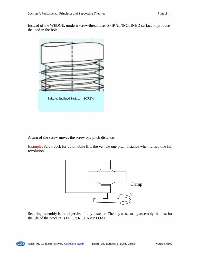
Instead of the WEDGE, modern screw/thread uses SPIRAL/INCLINED surface to produce the load in the bolt. A turn of the screw moves the screw one pitch distance. Example: Screw Jack for automobile lifts the vehicle one pitch distance when turned one full revolution. Securing assembly is the objective of any fastener. The key to securing assembly that last for the life of the product is PROPER CLAMP LOAD.
Clamp T
Spiraled Inclined Surface – SCREW
Spiraled Inclined Surface – SCREW
Section A Fundamental Principles and Supporting Theories Page A - 5
Nutek, Inc. All Rights Reserved. www.nutek-us.com Design and Behavior of Bolted Joints Version: 0602
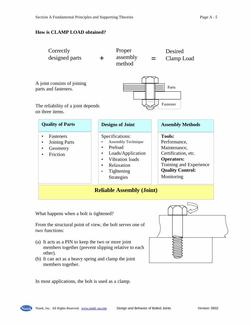
How is CLAMP LOAD obtained?
A joint consists of joining parts and fasteners. The reliability of a joint depends on three items.
What happens when a bolt is tightened? From the structural point of view, the bolt serves one of two functions: (a) It acts as a PIN to keep the two or more joint
members together (prevent slipping relative to each other).
(b) It can act as a heavy spring and clamp the joint members together.
In most applications, the bolt is used as a clamp.
Correctly designed parts +
Proper assembly method
= Desired Clamp Load
Parts
Fasteners
Quality of Parts
• Fasteners • Joining Parts • Geometry • Friction
Designs of Joint
Specifications: • Assembly Technique • Preload • Loads/Application • Vibration loads • Relaxation • Tightening
Strategies
Assembly Methods
Tools: Performance, Maintenance, Certification, etc. Operators: Training and Experience Quality Control: Monitoring
Reliable Assembly (Joint)

Section A Fundamental Principles and Supporting Theories Page A - 6
Nutek, Inc. All Rights Reserved. www.nutek-us.com Design and Behavior of Bolted Joints Version: 0602
Regardless of the way it functions, the bolt must be tightened properly in order for it to perform the intended function. When we tighten the bolt (by turning the head in above case or by turning the nut while the head is held fixed), we stretch the bolt slightly. The stretching does not occur, of course, until the bolt has made solid contact with the part. The clamping force is produced only when the bolt is stretched. The bolt therefore, must be stretched to be effective as a clamp. The stretch creates strain, which then produce tensile stress in the bolt. The tensile load in the bolt causes friction torque between the bolt and the joint surfaces and between the bolt and the joint threads. The torsional stress produced due to friction toque can be as much as 1/3 to ½ the tensile stress in the bolt. When we stop tightening, a good portion of both the tensile and torsional stresses disappear. This is primarily due to relaxation (10 – 20% in first few minutes) and localized plastic deformation. The initial clamping load or tension generated in the bolt (which is called as preload) is the objective of tightening a bolt in application. For economical design of a joint, it is necessary that CORRECT preload is obtained. Too much preload Fastener or joint fails prematurely Too little preload Risks other types of failure (more common) Where is a bolt most likely to fail? Bolt material is most likely to fail at locations where stress exceeds the material strength. Commonly, stress concentrations create stress level to rise beyond the average value. There are three points in the bolt, as called out in the joint shown, at which the bolt will usually fail. • Head to body fillet • Thread Run-out • First thread at engagement (In common
applications, the first three engaged threads carry most of the final clamp load)
To understand completely the behavior of a bolted joint in terms of its strengths, weaknesses and failure mechanisms, we must first review the applicable principles of:
Fillet at head to body section
Thread Run-out
First engaging thread
Section A Fundamental Principles and Supporting Theories Page A - 7
Nutek, Inc. All Rights Reserved. www.nutek-us.com Design and Behavior of Bolted Joints Version: 0602
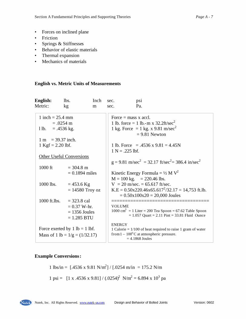
• Forces on inclined plane • Friction • Springs & Stiffnesses • Behavior of elastic materials • Thermal expansion • Mechanics of materials English vs. Metric Units of Measurements English: lbs. Inch sec. psi Metric: kg m sec. Pa. Example Conversions : 1 lbs/in = [.4536 x 9.81 N/m2] / [.0254 m/in = 175.2 N/m 1 psi = [1 x .4536 x 9.81] / (.0254)2 N/m2 = 6.894 x 10³ pa
1 inch = 25.4 mm = .0254 m l lb. = .4536 kg. 1 m = 39.37 inch. 1 Kgf = 2.20 lbf. Other Useful Conversions 1000 ft = 304.8 m = 0.1894 miles 1000 lbs. = 453.6 Kg = 14580 Troy oz 1000 ft.lbs. = 323.8 cal = 0.37 W-hr. = 1356 Joules = 1.285 BTU Force exerted by 1 lb = 1 lbf. Mass of 1 lb = 1/g = (1/32.17)
Force = mass x accl. 1 lb. force = 1 lb.-m x 32.2ft/sec2 1 kg. Force = 1 kg. x 9.81 m/sec2 = 9.81 Newton 1 lb. Force = .4536 x 9.81 = 4.45N 1 N = .225 lbf. g = 9.81 m/sec2 = 32.17 ft/sec2= 386.4 in/sec2 Kinetic Energy Formula = ½ M V2 M = 100 kg. = 220.46 lbs. V = 20 m/sec. = 65.617 ft/sec. K.E = 0.50x220.46x65.6172/32.17 = 14,753 ft.lb. = 0.50x100x20 = 20,000 Joules ==================================== VOLUME 1000 cm3 = 1 Liter = 200 Tea Spoon = 67.62 Table Spoon = 1.057 Quart = 2.11 Pint = 33.81 Fluid Ounce ENERGY 1 Calorie = 1/100 of heat required to raise 1 gram of water from 1 – 100o C at atmospheric pressure. = 4.1868 Joules

Section A Fundamental Principles and Supporting Theories Page A - 8
Nutek, Inc. All Rights Reserved. www.nutek-us.com Design and Behavior of Bolted Joints Version: 0602
1 inch/sec = .0254 m/sec 1 in.lbf = .0254 x (.4536 x 9.81) = .113 Nm 1 horsepower = 745.7 watt Types of Loads Loads are always represented by a force vector in a Free Body Diagram. Causes of loads:
- gravitational (weight) - mechanically applied - inertial - magnetic
Method of load transfers:
- Body-Contact loads Any force transmitted to a body from another by means of direct contact over an area. • Point • Line always normal to the • Distributed contact surface.
- Friction load/force
This force acts parallel to the contact area and is a function of normal load, the materials in contact and the relative velocity of the contacting surface.
Physics of Stationery Bodies Force = mass x accl. (Newton’s law). 1 unit of force (Newton) = 1 kg. 1 m/sec2 1 lb. = force exerted on 1 lb. mass by gravity. Force is designated by a VECTOR ↓↑ (A line with an arrow). A vector had a magnitude and a direction.
1 lbm 1 lbf
1 lb. 1 Kg.

Section A Fundamental Principles and Supporting Theories Page A - 9
Nutek, Inc. All Rights Reserved. www.nutek-us.com Design and Behavior of Bolted Joints Version: 0602
Free Body Diagram (FBD) FBD is a graphical representation of a body with its supports/attachments replaced by force.
String Weight W
Free Body Diagram (FBD) Tension T Weight W
FBD T1 T2 W W
Free Body Diagram (FBD)
W W R1 R2
Free Body Diagram (FBD)

Section A Fundamental Principles and Supporting Theories Page A - 10
Nutek, Inc. All Rights Reserved. www.nutek-us.com Design and Behavior of Bolted Joints Version: 0602
W W 90o R R
Free Body Diagram (FBD)
H
W W
V
Free Body Diagram (FBD)
Free Body Diagram (FBD)
Section A Fundamental Principles and Supporting Theories Page A - 11
Nutek, Inc. All Rights Reserved. www.nutek-us.com Design and Behavior of Bolted Joints Version: 0602
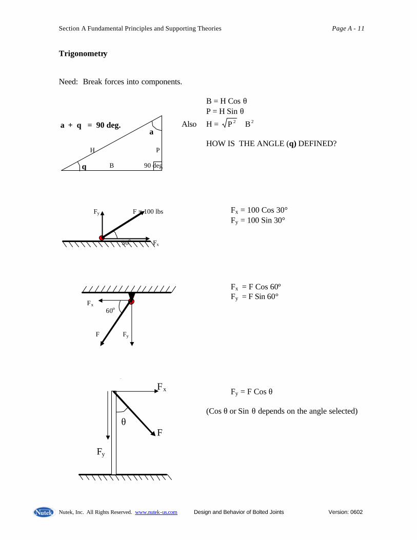
Trigonometry Need: Break forces into components. B = H Cos θ P = H Sin θ
Also H = 22 BP + HOW IS THE ANGLE (θ) DEFINED? Fx = 100 Cos 30° Fy = 100 Sin 30° Fx = F Cos 60° Fy = F Sin 60° Fx = F Sin θ Fy = F Cos θ
(Cos θ or Sin θ depends on the angle selected)
Fy F = 100 lbs 30o Fx
α + θ = 90 deg. H P B 90 deg
α
θ
Fx 60o F Fy
Fx
θ F Fy

Section A Fundamental Principles and Supporting Theories Page A - 12
Nutek, Inc. All Rights Reserved. www.nutek-us.com Design and Behavior of Bolted Joints Version: 0602
Rigid Body in a State of Equilibrium Sum of forces in a particular direction must equal zero.
W W R
Σ FV = 0 ↑+ R - W = 0 Or R = W
W W 90o R R
Σ FV = 0 ↑+ 2R Cos 45 - W = 0 or R = W / 2R Cos 45
R T T = W W W
Σ FV = 0 ↑+ R – 2W = 0 or R = 2W

Section A Fundamental Principles and Supporting Theories Page A - 13
Nutek, Inc. All Rights Reserved. www.nutek-us.com Design and Behavior of Bolted Joints Version: 0602
Bolt Load and the Free Body Diagram (FBD)
F R/2 R/2 R/2 R/2
Fn = W Cos 30 and Fp = W Sin 30
W Fp 30 30 W Fn
Force (F) required to push W up the incline? F = F Sin α = 100 Sin 30 Or F = 50 lbs. F 100 lbs. α

Section A Fundamental Principles and Supporting Theories Page A - 14
Nutek, Inc. All Rights Reserved. www.nutek-us.com Design and Behavior of Bolted Joints Version: 0602
Effect of Friction
Frictional force ∝ normal load FP = force required to slide the block W = Weight of block µ= friction coefficient between the surfaces Friction force always opposes the force ΣFH = o→ + trying to move the body. FP + µw = o or FP =o = µw Or µ = o no friction FP = µw = .1 x 100 = 10 lbs.
FP = .6 x 200 = 120 lbs.
FP = µw
Fp W Fp W µ W
Fp W µ = 0 Fp 100 lbs µ= .1 Fp
200 lbs µ = .6
Section A Fundamental Principles and Supporting Theories Page A - 15
Nutek, Inc. All Rights Reserved. www.nutek-us.com Design and Behavior of Bolted Joints Version: 0602
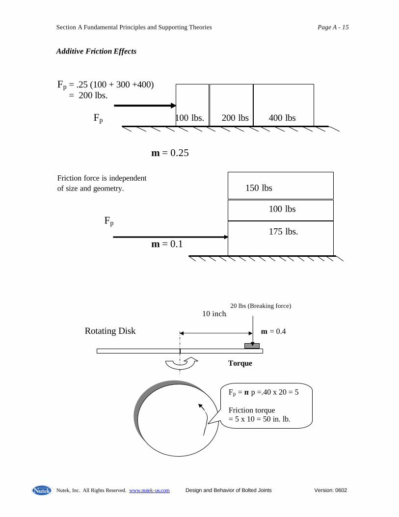
Additive Friction Effects
Fp = .25 (100 + 300 +400) = 200 lbs.
Fp 100 lbs. 200 lbs 400 lbs
µ = 0.25 Friction force is independent of size and geometry. 150 lbs 100 lbs Fp 175 lbs. µ = 0.1
20 lbs (Breaking force) 10 inch. Rotating Disk µ = 0.4
Torque
Fp = µ p =.40 x 20 = 5 Friction torque = 5 x 10 = 50 in. lb.
Section A Fundamental Principles and Supporting Theories Page A - 16
Nutek, Inc. All Rights Reserved. www.nutek-us.com Design and Behavior of Bolted Joints Version: 0602
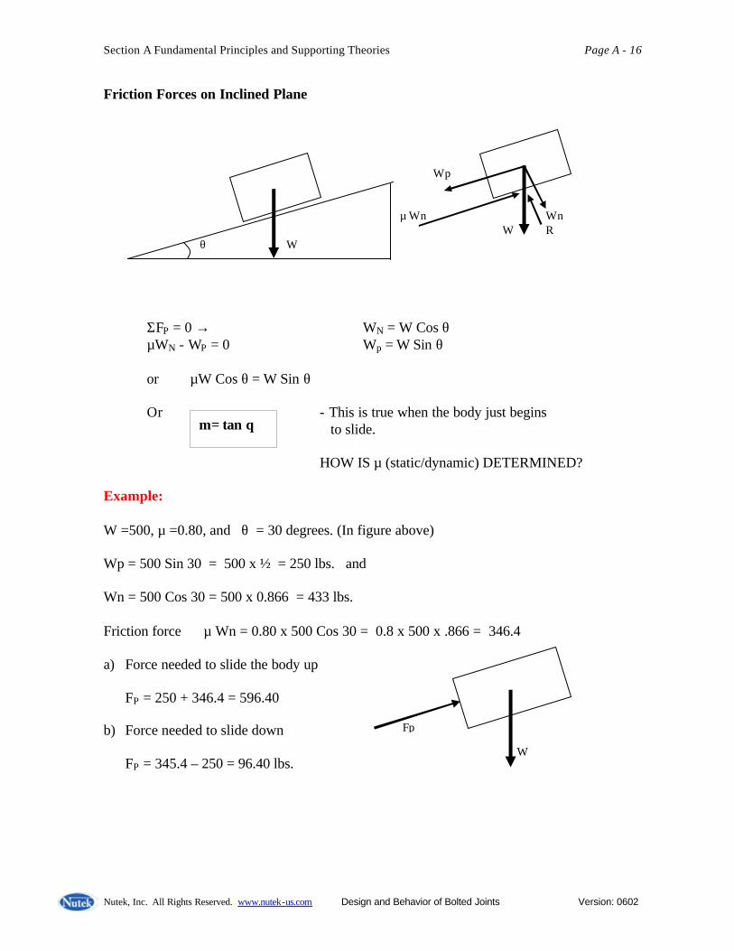
Friction Forces on Inclined Plane
ΣFP = 0 →+ WN = W Cos θ µWN - WP = 0 Wp = W Sin θ or µW Cos θ = W Sin θ Or - This is true when the body just begins to slide.
HOW IS µ (static/dynamic) DETERMINED? Example: W =500, µ =0.80, and θ = 30 degrees. (In figure above) Wp = 500 Sin 30 = 500 x ½ = 250 lbs. and Wn = 500 Cos 30 = 500 x 0.866 = 433 lbs. Friction force µ Wn = 0.80 x 500 Cos 30 = 0.8 x 500 x .866 = 346.4 a) Force needed to slide the body up
FP = 250 + 346.4 = 596.40
b) Force needed to slide down
FP = 345.4 – 250 = 96.40 lbs.
µ = tan θ
Wp µ Wn Wn W R θ W
θ
Fp
W

Section A Fundamental Principles and Supporting Theories Page A - 17
Nutek, Inc. All Rights Reserved. www.nutek-us.com Design and Behavior of Bolted Joints Version: 0602
Principles of Conservation of Energy Work done in lifting weight = 200 x 5 = 1,000 in lb. Tan 30° = 5”/H or H = 5/Tan30° = 8.66 in. Work done by FP in moving the block/wedge (Assume no friction at contact surface.) = FP x H = FP(8.66) Work done by the wedge is same as the potential energy gained by the weight Or FP 8.66 = 1,000 in lb. Or FP = 1,000/8.66 = 115.4 lbs.
200 lbs 5 “ Wedge Fp 30 30

Section A Fundamental Principles and Supporting Theories Page A - 18
Nutek, Inc. All Rights Reserved. www.nutek-us.com Design and Behavior of Bolted Joints Version: 0602
250 lbs. 60 degrees
Topics Group Exercises
Units/ measure
1 in = 25.4 mm 1lb = 453.6 gm 1 kg = 9.81 N 1 lf = 4.45 N
A-1 a: The diameter of the Earth is about 4,000 miles. What is the value in KM? b: The yield stress of a material is specified as 206.82 mpa (Mega Pascal, N/m2). What is the value expressed in psi. (Ans: 30,000 psi) c: The tension in a string is specified as 13,350 N. What is the tension value in terms of lbs force? d: If the acceleration due to gravity is 32.2 ft/sec2., show that the value in metric system is approximately 9.81 m/sec2.
Trigonometry Sin 0 = 0 Sin 30 =0.50 Sin 45 = 0.707 Sin 60 = 0.866 Sin 90 = 1.0
A-2 a: A 5,500 lbs vehicle is skidded into a ditch that has 45% ramp. What is the force parallel to the ramp the toe truck has to apply (parallel to the ramp) to pull the vehicle out of the ditch? (Ignore road/dirt friction). b: The guy wires (60 degrees with horizontal) for a television tower are set at 25,000 lbs of total tension. Determine the axial force sustained by the tower? c: A 20 ft. long ladder is to carry 250 lbs. (W) load at its center, is placed against a wall at 60 degrees angle with ground. If the vertical wall can only support 65 lbs. of horizontal load, is it safe to rest the ladder against it?

Section A Fundamental Principles and Supporting Theories Page A - 19
Nutek, Inc. All Rights Reserved. www.nutek-us.com Design and Behavior of Bolted Joints Version: 0602
F I II III
θ =15 deg. W
Wp θ W µ Wn W R Wn
θ
Topics Group Exercises
Friction
FP = µw
A-3 a. Three blocks of different weights and friction coefficients, rest on a rough surface. Determine the force, F, necessary to push the block. I Steel 300 lbs. Friction µ = 0.25 II Cast Iron 400 lbs. Friction µ = 0.40 III Wood 250 lbs. Friction µ = 0.20
b. What is the work done in pushing a 5,000 lbs. vehicle up the hill (15 deg.) 200 ft. if the friction is assumed to be absent? If the friction between vehicle and the road, µ = 0.10 , what is magnitude of the force necessary to pull the vehicle up the hill?
At equilibrium WN = W Cos θ µWN - WP = 0 Wp = W Sin θ µ = tan θ
c. The friction coefficient (µ) is dependent on the contacting materials and can be easily determined in laboratory environment. In the following set up, the block just begins to slide down the incline when the ramp angle is increased to 26 deg. Determine the coefficient of friction between the block and the ramp materials.
Section A Fundamental Principles and Supporting Theories Page A - 20
Nutek, Inc. All Rights Reserved. www.nutek-us.com Design and Behavior of Bolted Joints Version: 0602
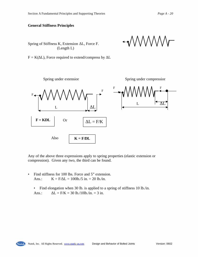
General Stiffness Principles Spring of Stiffness K, Extension ∆L, Force F. (Length L) F = K(∆L), Force required to extend/compress by ∆L Or Also Any of the above three expressions apply to spring properties (elastic extension or compression). Given any two, the third can be found. • Find stiffness for 100 lbs. Force and 5” extension.
Ans.: K = F/∆L = 100lb./5 in. = 20 lb./in.
• Find elongation when 30 lb. is applied to a spring of stiffness 10 lb./in. Ans.: ∆L = F/K = 30 lb./10lb./in. = 3 in.
F = K∆L ∆L = F/K
K = F/∆L
Spring under extension F F
L ∆L
Spring under compression F F
L ∆L
Section A Fundamental Principles and Supporting Theories Page A - 21
Nutek, Inc. All Rights Reserved. www.nutek-us.com Design and Behavior of Bolted Joints Version: 0602
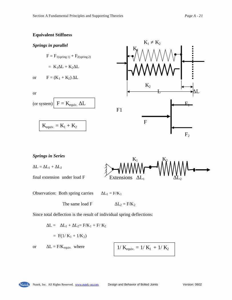
Equivalent Stiffness Springs in parallel F = F1(spring 1) + F2(spring 2)
= K1∆L + K2∆L or F = (K1 + K2) ∆L or (or system) Springs in Series ∆L = ∆L1 + ∆L2 final extension under load F Observation: Both spring carries ∆L1 = F/K1 The same load F ∆L2 = F/K2 Since total deflection is the result of individual spring deflections: ∆L = ∆L1 + ∆L2= F/K1 + F/ K2 = F(1/ K1 + 1/K2) or ∆L = F/Kequiv. where
1/ Kequiv. = 1/ K1 + 1/ K2
F = Kequiv. ∆L
Kequiv. = K1 + K2
K1 ≠ K2
K1 K2 L ∆L F1 F1 F F2
K1 K2 Extensions ∆L1 ∆L2

Section A Fundamental Principles and Supporting Theories Page A - 22
Nutek, Inc. All Rights Reserved. www.nutek-us.com Design and Behavior of Bolted Joints Version: 0602
Stress, Strain and Mechanical Properties of Materials A rod or any other rigid body under load also behaves the same as springs. (up to a point) For materials like steel, Aluminum, Plastic, wood, etc. plot of stress And strain yields some values that Hold true regardless of geometry. Stress = Load/area (P/A) (σ) Strain = Deformation/Length (∆L/L) Many materials exhibit ELASTIC (like spring) behavior shows: Stress/Strain = Constant* = E E = Young’s Modulus. HOW IS IT DETERMINED?
Rod P P P
Elongation, ∆L
Spring Force (F) Force (F) Deflection (X) Deflection (X)
St. Line
Yield Strength Stress
0.2 % offset Strain (ε)
Line paralle l to the stress/strain line

Section A Fundamental Principles and Supporting Theories Page A - 23
Nutek, Inc. All Rights Reserved. www.nutek-us.com Design and Behavior of Bolted Joints Version: 0602
*We encounter many constants in engineering and science. Some are universal, others hold true for a group or type of subjects. And there are some that are only fixed for a particular condition. E is such a constant for a material. (E = 30 x 106 psi regardless of size, shape or hardness) Similarly, if a rod is subjected to torsion, its torsional strength and property can be determined. Shear Stress/(↑)/Shear Strain (γ) = G, Rigidity Modus
Strain along X causes proportional strain in the other two perpendicular directions. εy = -µεx and εz = -µεx µP = Poisson’s ratio
Torque T
Strain γ L
Shear Stress (τ) Shear Strain ( γ )
Y X P P L ∆L

Section A Fundamental Principles and Supporting Theories Page A - 24
Nutek, Inc. All Rights Reserved. www.nutek-us.com Design and Behavior of Bolted Joints Version: 0602
Properties of Engineering Materials In typical fasteners, say bolts, the torsional load is negligible and the transverse deformation is minimal. • Yield Strength, Strength, • Ultimate Strength, and • Fracture Strength. All refer to the stress values at the conditions applicable. Yield Stress (σy) is generally used for design purposes. E = σ/ε in the elastic range i.e. σy > σ (Axial load only)
Also since σ = P/A, ε = ∆L/L P/A = E ∆L/L Or This equation is similar to F = K x for spring
Where F = P Force applied X = ∆L Elongation under axial load K = (AE/L) Stiffness of the body
σy, σu, etc. will vary for the same material depending on the hardness. But E, G and µ do not. G = E/2(1 + µ)
P = (AE/L) ∆L
Stress 2 3 1 Strain
1. Yield Stress 2. Ultimate Stress 3. Fracture Strength
Section A Fundamental Principles and Supporting Theories Page A - 25
Nutek, Inc. All Rights Reserved. www.nutek-us.com Design and Behavior of Bolted Joints Version: 0602
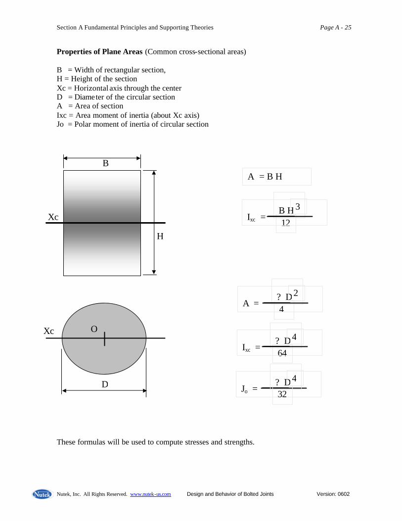
Properties of Plane Areas (Common cross-sectional areas) B = Width of rectangular section, H = Height of the section Xc = Horizontal axis through the center D = Diameter of the circular section A = Area of section Ixc = Area moment of inertia (about Xc axis) Jo = Polar moment of inertia of circular section These formulas will be used to compute stresses and strengths.
B H 3
12
Ixc =
A = B H
Jo =
? D 4
324
? D 4
64
Ixc =
? D 2
4
A =
Xc
H
B
Xc O
D

Section A Fundamental Principles and Supporting Theories Page A - 26
Nutek, Inc. All Rights Reserved. www.nutek-us.com Design and Behavior of Bolted Joints Version: 0602
Basic Relationships of Load, Stress, Strain, and Stiffness Stiffness of a rod, K = P/ ?L = (A s )/ ?L = ( A (E e) )/ ?L = (AE)x (e /?L) = AE/L Or K = AE/L Example: Find elongation under 20,000 lb. tension ½” dia, 5” long rod. E = 30 x 106 psi A = π/4 x (1/2)2 = π/16 K = π/16 x 30 x 106/5 = 1.18 x 10⁶ lbs./in. Elongation
F = K∆L Or ∆L = K/F = 1.18 x 10⁶/20,000 = .006
A, E
Stiffness K = (AE/L)
Stiffness of spring, K
20,000 lbs. 5 “
Load & Stress P = A s
Stress & Strain s = E e
Strain & Elongation e = ?L/L Stiffness & Load K = P/?L

Section A Fundamental Principles and Supporting Theories Page A - 27
Nutek, Inc. All Rights Reserved. www.nutek-us.com Design and Behavior of Bolted Joints Version: 0602
Example:
Find force required to Compress the column by 3 mm (E = 30 x 106 psi) Ans.:
E = 30 x 106 lbs./in2 = 30 x 106 x 4.45N/(.0254) 2
= 206.9 x 10³Mpa [ 106pa = 1Mpa, 1 pa = 1N/m2 ] K = ∆E/L = 12 x 12/40 x 100 x 206.9 103 x 106 N/m Or K = 744.8 x 10³ N/mm But P = (K) ∆L = 744.x x 103 x 3 = 2.234 x 10⁶N
Example: How much would a ½” dia. Bolt extends under 45,000 tension. (E = 30 x 106 psi) P = (AE/L) ∆L 45,000 = AE ∆L/L = π(.5)2 x 30 x 106/4 x 5 ∆L 45 x 103 = 1,177.5 x 103 ∆L Or ∆L = 45/1,177.5 = .038 in. Ans.: .038 in.
What are Elongation, Extension, Compression, Tension, Load, and Strength?
P 3 mm 40 mm 12 x 12 mm
45,000 lbs. 5 “

Section A Fundamental Principles and Supporting Theories Page A - 28
Nutek, Inc. All Rights Reserved. www.nutek-us.com Design and Behavior of Bolted Joints Version: 0602
Example: Axial, Bending, and Shear stresses in rod of circular section Axial stress
s a = F / A = 200,000 / (3.14159x36/4) = 7,073 lbs/sq.in. (uniform) Bending stress
s b = M (D/2)/I = (20x12,000)x3 / (3.14159x36x36/64) = 11,317 lbs/sq.in. Torsional (Shear) stress t t = T (D/2) / J = (90,000 x 3)/ (3.14159x36x36/32) = 2,122 lbs/sq.in. Vertical shear stress t v = P /A = 12,000/ (3.14159x36x36/4) = 428 lbs/sq.in (uniform) Stresses at the upper fiber of the shaft are as shown below.
s a
s b
t v
t t
s a + s b X
P = 12,000 Lbs.
T = 90,000 in. Lbs.
F = 200,000 Lbs. 6 in. Dia. 20 in long
X

Section A Fundamental Principles and Supporting Theories Page A - 29
Nutek, Inc. All Rights Reserved. www.nutek-us.com Design and Behavior of Bolted Joints Version: 0602
Stress Due to Bending Load Ix = bh3/12 Stress at a fiber C in away from the center of the area. σ = MC/I, M = bending movement (Area Moment of Inertia) Ix = πd4 / 64 Maximum moment at base = P.L. lb.in. Max. Stress σstress = (PL)/I (d/2)
= [PL/(πd4 )](d/2) x 64
σmax = 32PL/(πd3 )
Compression Tension
b c h
d
P d L d

Section A Fundamental Principles and Supporting Theories Page A - 30
Nutek, Inc. All Rights Reserved. www.nutek-us.com Design and Behavior of Bolted Joints Version: 0602
Combined Axial & Bending Loads Often bolts are subjected to combined loading. Pa = axial tension Pb = bending load Maximum tensile stress will occur at point P1 σmax =( Pa/a) + ( PbL / I ) (d/2)
Bolt fails when the stress due to combined/single loading exceeds the ultimate strength of the bolt material. For design purposes, steel bolts are designed to withstand 25,000 psi. Special and hardened bolts carry much higher stress levels. Example: A 5/8"- 18 bolt UNF threads is subjected to axial load Pa = 2,500 lbs and bending load at 3.5” unsupported bolt length. If the yield strength of the fastener material 35,000 psi, find the safe bending load, Pb, that can be safely applied to the bolt as shown. Solution: σmax =( Pa/a) + ( PbL / I ) x (d/2) a = 0.785 x (5/8)2 = 0.307 I = 3.14 x (5/8)4 /64 = 0.00749
35,000 = 2,500/0.307 + ( Pb x 3.5/ 0.00749) x (5/16) or 35,000 = 8,143 + 146 Pb or Pb = (3,500 – 8,143)/146 = 184 lbs.
Pa Pb E, L a, I d
P2 P1
L

Section A Fundamental Principles and Supporting Theories Page A - 31
Nutek, Inc. All Rights Reserved. www.nutek-us.com Design and Behavior of Bolted Joints Version: 0602
Other Modes of Bolt Failures Tensile Failure Maximum Strength (Load capacity) = s u x AS AS = Thread stress area under tensile load. Single Shear Failure Maximum Strength = t max x (0.785 x D2) Double Shear Failure Maximum Strength = t max x 2x (0.785 x D2) (Adjust if threaded area is involved) Thread Stripping
Thread run-out
Neck
Thread engagement length

Section A Fundamental Principles and Supporting Theories Page A - 32
Nutek, Inc. All Rights Reserved. www.nutek-us.com Design and Behavior of Bolted Joints Version: 0602
Equivalent Joint Stiffness Stiffnesses in Series Stiffnesses in Parallel
Characteristics of springs in parallel or series configurations: When forces are equal in two connected springs, they are in SERIES. When displacements in both springs are equal, they are in PARALLEL.
K1 K2 1/Kequiv = 1/K1 + 1/K2
1/Kequiv =1/(A1E1/L1) + (A2E2 /L2) A1 E1 L1 A2 E2L2
K1 ≠ K2
K1 Equivalent Stiffness
Kequiv = K1 + K2 K2 L ∆L A1E1L1 Kequiv = (A1E1 / L1 ) + (A2E2/L2) A2 E2L2
Section A Fundamental Principles and Supporting Theories Page A - 33
Nutek, Inc. All Rights Reserved. www.nutek-us.com Design and Behavior of Bolted Joints Version: 0602
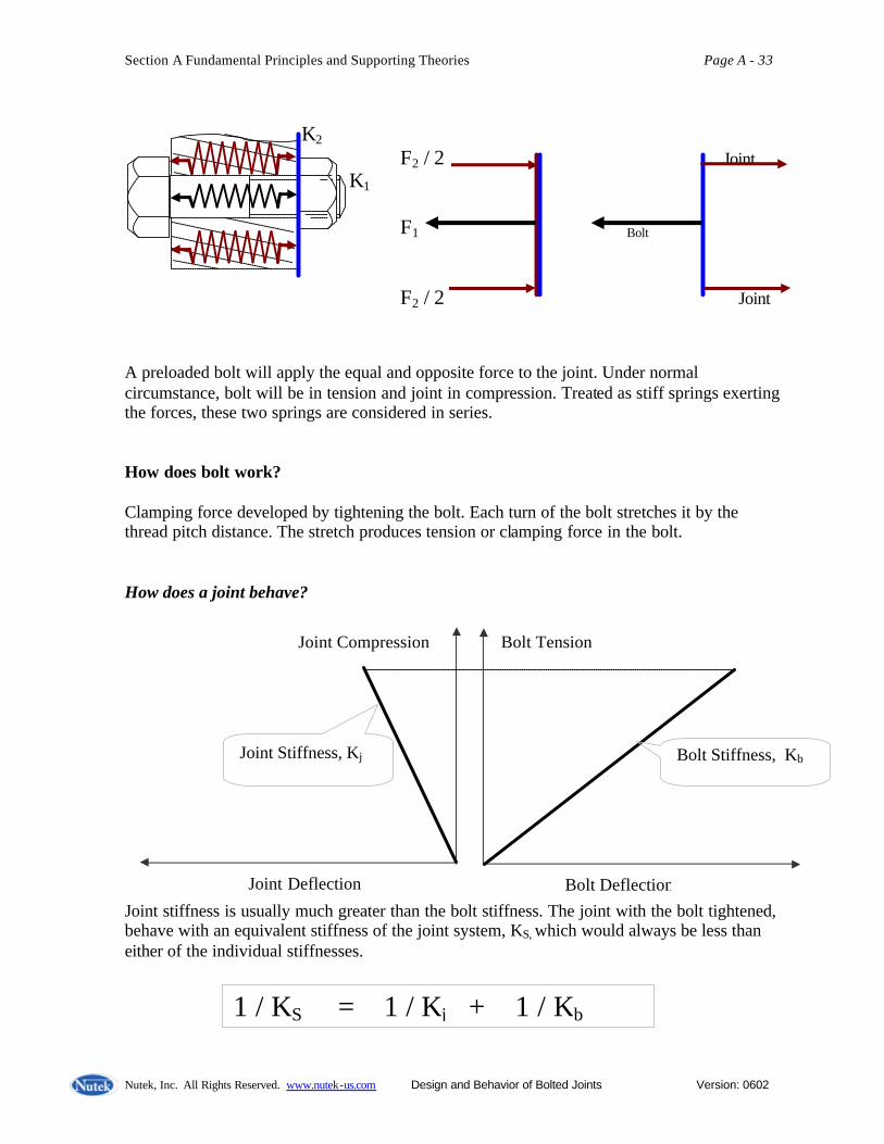
A preloaded bolt will apply the equal and opposite force to the joint. Under normal circumstance, bolt will be in tension and joint in compression. Treated as stiff springs exerting the forces, these two springs are considered in series. How does bolt work? Clamping force developed by tightening the bolt. Each turn of the bolt stretches it by the thread pitch distance. The stretch produces tension or clamping force in the bolt. How does a joint behave?
Joint stiffness is usually much greater than the bolt stiffness. The joint with the bolt tightened, behave with an equivalent stiffness of the joint system, KS, which would always be less than either of the individual stiffnesses.
Joint Deflection
Joint Compression
Bolt Deflection
Bolt Tension
Bolt Stiffness, Kb
Joint Stiffness, Kj
1 / KS = 1 / Kj + 1 / Kb
K2 F2 / 2 Joint K1 F1 Bolt
F2 / 2 Joint

Section A Fundamental Principles and Supporting Theories Page A - 34
Nutek, Inc. All Rights Reserved. www.nutek-us.com Design and Behavior of Bolted Joints Version: 0602
What should be the nature of the combined stiffness relative to the same for bolt & joint? Equivalent Bolt Stiffness and Total Bolt Stretch Formula
Generally joint is much stiffer than the bolt. Kj = 10,000 lbs/ .001 in = 10x106 lbs/in Kb = 10,000 lbs / .005 in = 2x10⁶ lbs/in 1 / KS = 1 / Kj + 1 / Kb
Or 1 / KS = ( 1 / 10 + 1 / 2 ) x 106 lbs/in KS = (10 / 6) x 106 lbs/in = 1.67 x 10⁶ lbs/in Once the stiffness is known, it can be used to estimate the load for a certain deflection. Or, when the load is known, the deflection can be calculated. F = K ∆L or ∆L = F/K or K = F / ∆L Observation: The equivalent stiffness of two springs is always lower than the smaller of the two components.
Joint Deflection
Joint Compression
Bolt Deflection
Bolt Tension
Equivalent Stiffness, KS

Section A Fundamental Principles and Supporting Theories Page A - 35
Nutek, Inc. All Rights Reserved. www.nutek-us.com Design and Behavior of Bolted Joints Version: 0602
1 / KS = 1 / Kj + 1 / Kb or KS = ( Kj x Kb )/ (Kj + Kb) Example Equivalent Stiffnesses: K1 = 2 lb/in, K2 = 2 lb/in. KEqv. = ( K1 x K2 )/ (K1 + K2 ) = 4/4 = 1 lb/in. K1 = 4 lb/in, K2 = 20 lb/in. KEqv. = ( K1 x K2 )/ (K1 + K2 ) = 80/24 = 3.33 lb/in. K1 = 24 lb/in, K2 = 300 lb/in. KEqv. = ( K1 x K2 )/ (K1 + K2 ) = 7200/324 = 22.2 lb/in. K1 = 20 lb/in, K2 = 1000 lb/in. KEqv. = ( K1 x K2 )/ (K1 + K2 ) = 20,000/1020 = 19.6 lb/in. Notice that the equivalent stiffness range between 50 – 100% for the difference in values from 0 – very large. BOLT GEOMETRY Notations Used: TH = Length of bolt head TN = Length of nut LS = Length solid bolt head LT = Length threaded bolt head k = Constant (0.5 for head, 0.6 for nut)) LAE = Equivalent length of A LAE = Equivalent length of B LE = Equivalent bolt length AA = Stress area of A AB = Stress area of B E = Modulus of elasticity ? LT = Total length changes of all portion KA, KB = Stiffnesses of portion A & B LE = LAE + LBE = LS + k TH + LT + k TN ?LT = FB x (1/KA + 1/KB ) =
TH LS LT TN
LAE = LS + k TH LBE = LT + k TN
A B FB
FB LEB
EBA FB LEA
EAA +

Section A Fundamental Principles and Supporting Theories Page A - 36
Nutek, Inc. All Rights Reserved. www.nutek-us.com Design and Behavior of Bolted Joints Version: 0602
US Nut Size Table
Height of hex nut and bolt head range between 60% - 90% of bolt diameter. For specific bolt, the exact dimension should be selected from table.
Bolt Materials and Grades
Source: http://www.boltdepot.com A standard bolt has a hex head and a smooth shoulder area beyond the standard amount of threading. Shorter lengths are fully threaded.
Steel grade 2 Zinc plated low carbon steel. Best for general hardware use where high strength is not required.
Steel grade 5 Made from medium carbon steel, tempered and zinc plated. Best for automotive use and other areas where higher strength is desired.
Steel grade 8 Made from medium carbon alloy steel, tempered and yellow zinc plated. Best suited for applications where high strength and hardness is required.
Stainless steel 18-8 Stainless steel 18-8 is an alloy of steel with high corrosion resistance. Stainless has become the material of choice for exterior and most marine applications.
Grade 5 chrome A grade 5 fastener with a bright mirror-like finish providing sharp looks for a variety of applications.
Bolt grades and markings will be discussed later in this course.

Section A Fundamental Principles and Supporting Theories Page A - 37
Nutek, Inc. All Rights Reserved. www.nutek-us.com Design and Behavior of Bolted Joints Version: 0602
Example: Determine the equivalent length of a 1” dia. bolt with the dimension shown. Calculate equivalent lengths using 50% involvement of both bolt head and nut. Equivalent length, part A = 1.75 + 0.50 x 0.62 = 2.06 in. Equivalent length, part B = 0.50 + 0.50 x 0.85 = 0.925 in. Alternate form (when joint thickness is known) : Equiv length of part B = Joint Thickness - (Bolt Length – Threaded Length) + (TN) x 0.6 Example: For a bolt SAE J 05 and Nut SAE J 104 and ANSI B.1-1974 (thread), the dimensiona l specifications are as follows. Estimate the change in bolt length when subjected to maximum design load. Nominal Bolt Diameter (D) = 3/8 in.(0.375 in.) Bolt Length = 1.5 in. Height of nut (TN) = 0.3285 in. Height of head (TH) = 0.2354 in. Thread length (LT) = 1.00 in. Joint Thickness = 1.0 Tensile stress area of threads (AB) = 0.0775 in2. E = 30x106 psi, Yield Stress = 130 ksi
A B
0.62 1.75 0.50 0.85
Joint Thickness

Section A Fundamental Principles and Supporting Theories Page A - 38
Nutek, Inc. All Rights Reserved. www.nutek-us.com Design and Behavior of Bolted Joints Version: 0602
Solution
Portion A (Figure above) AA = ? D2/4 = ? x 0.3752 = 0.1104 in2
LAE = (1.5 – 1.0) + (TH)/2 = 0.6173 1/KA = (LAE)/(ExAA) = 0.6173 / (30 x 106 x 0.1104) = 0.1864x 10⁻⁶ or KA = 5.365 x 10⁶ in/lb
Portion B Area (AB) = 0.0775 in2. LBE = Joint Thickness - (Bolt Length – Threaded Length) + (TN) x 0.6 = 1.0 - (1.5 – 1.00) + 0.3285 x 0.6 = 0.697 1/KB = (LBE)/(ExAB) = 0.697 / (30 x 106 x 0.0775) = 0.2998x 10-6 KB = 3.336 x 10⁶ in/lb
Equivalent Stiffness of the bolt (KE) can be calculated using: 1/KE = 1/KA + 1/KB KE = (KA x KB)/(KA + KB) = (5.365 x 3.336)/(5.365 + 3.336) x 106
= 2.056 x 10⁶ lbs/in.
Assuming 60% of yield stress, 130 ksi, and bolt is subjected to stress of 78,000 psi. FB = 78,000 x 0.0775 = 6,045 lb Work done to stretch the bolt = (1/2) FB x ? LT Potential energy stored = (1/2) x FB x ? LT
Bolt length change (stretch, ?LT) can be calculated as:
?LT = FB x (1/KA + 1/KB ) = 6,045 / (2.056 x 10⁻⁶ ) = 0.00294 in.
Section A Fundamental Principles and Supporting Theories Page A - 39
Nutek, Inc. All Rights Reserved. www.nutek-us.com Design and Behavior of Bolted Joints Version: 0602
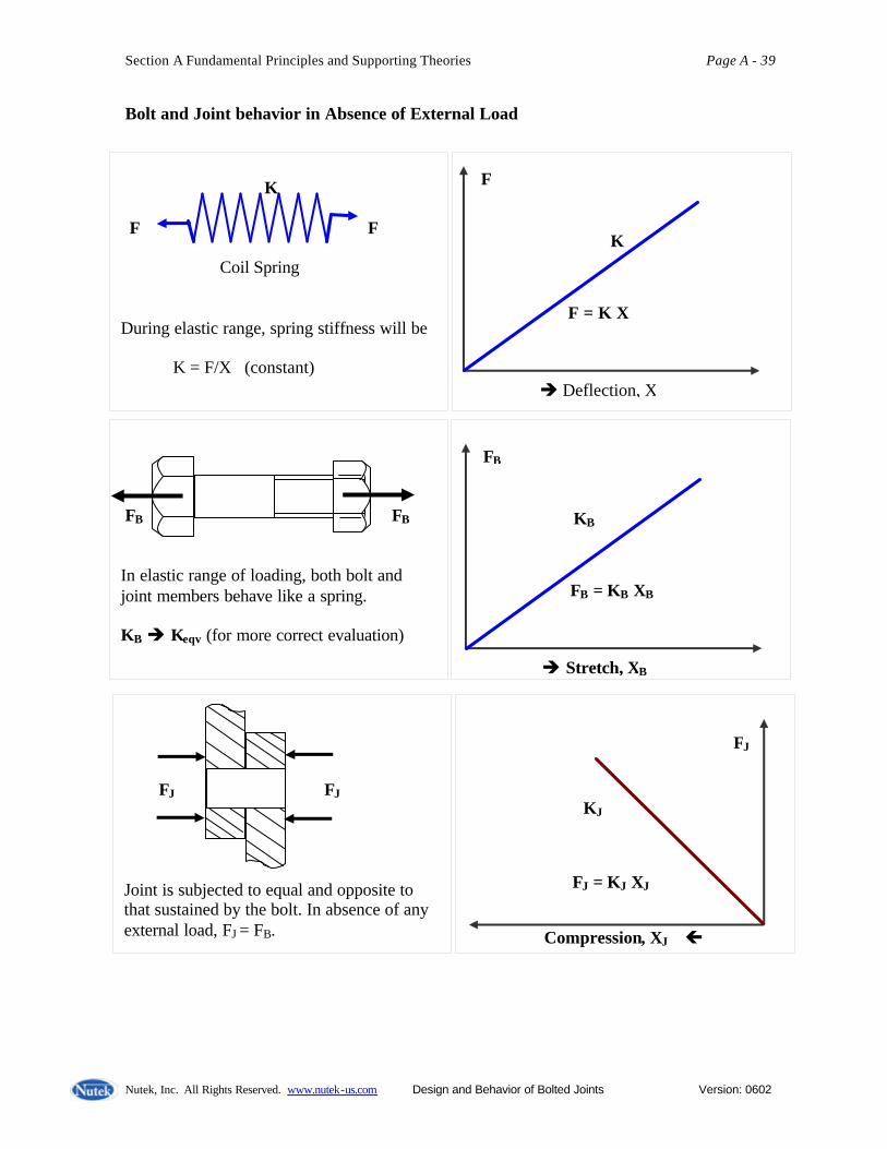
Bolt and Joint behavior in Absence of External Load
è Deflection, X
F
F = K X
K
K F F Coil Spring During elastic range, spring stiffness will be K = F/X (constant)
FB FB In elastic range of loading, both bolt and joint members behave like a spring. KB è Keqv (for more correct evaluation)
è Stretch, XB
FB
FB = KB XB
KB
FJ FJ Joint is subjected to equal and opposite to that sustained by the bolt. In absence of any external load, FJ = FB.
FJ = KJ XJ
Compression, XJ ç
FJ
KJ

Section A Fundamental Principles and Supporting Theories Page A - 40
Nutek, Inc. All Rights Reserved. www.nutek-us.com Design and Behavior of Bolted Joints Version: 0602
è Bolt Stretch, XB
FB
FJ = FB at all times
KB KJ
Joint Compression
Because the load in bolt and joint is always equal, the force-displacement plots for both can be shown using the same horizontal axes. Deflection of joint and bolt depends on their stiffnesses.
è Bolt Stretch, XB
FB
FJ = FB at all times
KB KJ
Joint Compression
Very stiff joint and softer bolt Joint stiffness>> Bolt stiffness
è Bolt Stretch, XB
FB
FJ = FB at all times KB
KJ
Joint Compression
Very stiff bolt and very soft joint members. Bolt stiffness>> Joint stiffness
Section A Fundamental Principles and Supporting Theories Page A - 41
Nutek, Inc. All Rights Reserved. www.nutek-us.com Design and Behavior of Bolted Joints Version: 0602
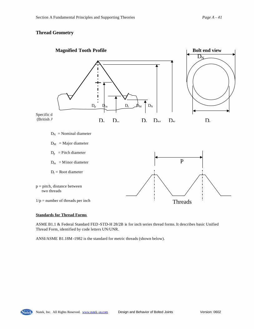
Thread Geometry Specific dimensions vary depending of the standard (British Association Standard, International Metric Standard) DN = Nominal diameter DM = Major diameter Dp = Pitch diameter Dm = Minor diameter Dr = Root diameter p = pitch, distance between two threads 1/p = number of threads per inch Standards for Thread Forms ASME B1.1 & Federal Standard FED -STD-H 28/2B is for inch series thread forms. It describes basic Unified Thread Form, identified by code letters UN/UNR. ANSI/ASME B1.18M -1982 is the standard for metric threads (shown below).
Magnified Tooth Profile Bolt end view DN Bolt Dp Dm Dr DM DN
Dp Dm Dr DM DN Dr
P Threads
Section A Fundamental Principles and Supporting Theories Page A - 42
Nutek, Inc. All Rights Reserved. www.nutek-us.com Design and Behavior of Bolted Joints Version: 0602
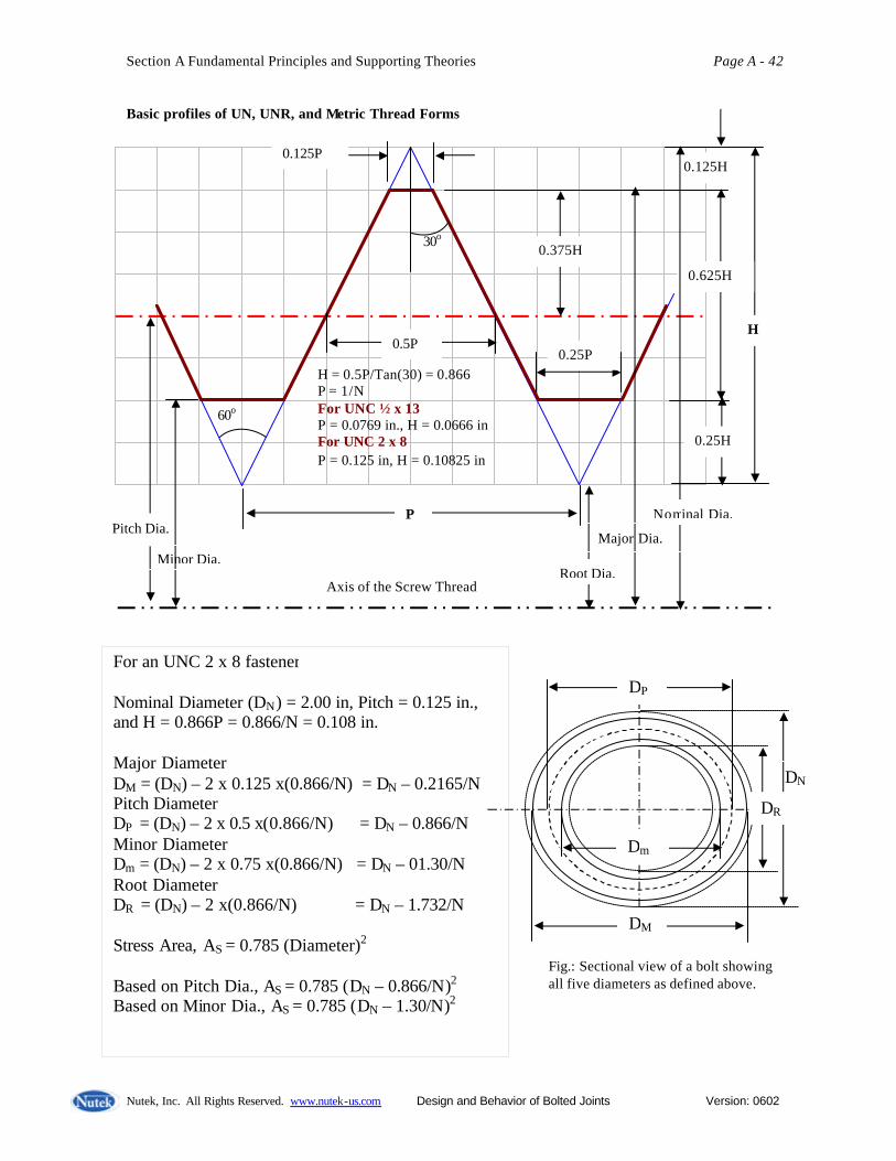
Basic profiles of UN, UNR, and Metric Thread Forms
P
0.5P
0.125P
0.25P
60o
H
0.625H
0.125H
0.25H
0.375H 30o
Pitch Dia.
Axis of the Screw Thread
H = 0.5P/Tan(30) = 0.866 P = 1/N For UNC ½ x 13 P = 0.0769 in., H = 0.0666 in For UNC 2 x 8 P = 0.125 in, H = 0.10825 in
Root Dia.
Nominal Dia.
Major Dia. Minor Dia.
For an UNC 2 x 8 fastener Nominal Diameter (DN) = 2.00 in, Pitch = 0.125 in., and H = 0.866P = 0.866/N = 0.108 in. Major Diameter DM = (DN) – 2 x 0.125 x(0.866/N) = DN – 0.2165/N Pitch Diameter DP = (DN) – 2 x 0.5 x(0.866/N) = DN – 0.866/N Minor Diameter Dm = (DN) – 2 x 0.75 x(0.866/N) = DN – 01.30/N Root Diameter DR = (DN) – 2 x(0.866/N) = DN – 1.732/N Stress Area, AS = 0.785 (Diameter)2 Based on Pitch Dia., AS = 0.785 (DN – 0.866/N)2 Based on Minor Dia., AS = 0.785 (DN – 1.30/N)2
DM
Dm
DP
DN
DR
Fig.: Sectional view of a bolt showing all five diameters as defined above.

Section A Fundamental Principles and Supporting Theories Page A - 43
Nutek, Inc. All Rights Reserved. www.nutek-us.com Design and Behavior of Bolted Joints Version: 0602
Stress Area for Threaded Bolt (Ref.2 Page 735) Experiments have demonstrated that a general purpose bolt will break in tensile stress through an equivalent solid shaft of diameter between the pitch diameter and the minor diameter. The cross-sectional area of this solid shaft is called the stress area, AS. Bolt strength = (Ultimate tensile stress) x AS For UN or UNR inch threads, the standard (ASME B1.1) value of stress area is given below (N = Number of threads per inch, P = 1/N, DN = Nominal diameter)
AS = 0.785 ( DN – 0.9743/N)2 ….. ( Use for inch threads)
For M-form (same as UNR, 60o included angle) metric threads, the standard (ASME B1.13M) value of stress area is
AS = 0.785 ( DN – 0.9382P)2 ….. ( Use for metric threads)
(Stress area differs for other thread profiles and are established similarly with experiments)
US Threads Per Inch Table
Threads Per Inch (TPI) Bolt Size Coarse Thread
UNC Fine Thread
UNF
#2 56 -
#10 24 32
#12 24 -
1/4 20 28
1/2 13 20
3/4 10 16
1 8 14
1-1/4 7 12
1-1/2 6 12

Section A Fundamental Principles and Supporting Theories Page A - 44
Nutek, Inc. All Rights Reserved. www.nutek-us.com Design and Behavior of Bolted Joints Version: 0602
Shear Failure of Threads Shear strength, FSh = t U x ASh Where t U = Ultimate shera stress ( taken as 50% of ultimate tensile stress, s U) ASh = Surface area through which shear occurs (tubular in shape for bolt/nut) Depending on the relative strength of bolt and nut, the tread failure will occur either in nut or bolt threads, or in both simultaneously. The shear stress area of failure is different for each of the failure types.
Bolt
Nut
Pitch Dia.
Tensile Load and Area
Shear Resistance and Area
(1) Failure when nut and bolt are of equal strength Failure occurs simultaneously in both parts at the pitch diameter. AS = Stress area for tensile failure (defined earlier) LE = Effective length of shear area. This is the length of the treaded are required to develop full strength. Full strength of bolt = AS x s U This must equal the resistance from shear area of length LE. At pitch diameter, perimeter = p DP Area of shear, ASh = p DP (1/2 x LE ) Note the shear width of thread at pitch diameter is half the pitch distance. Thus, for equal shear and tensile strength, ASh x t U = AS x s U Or p DP (1/2 x LE ) x (1/2 x s U) = AS x s U or LE = 4AS /(p DP) (LE = DN commonly used)
Section A Fundamental Principles and Supporting Theories Page A - 45
Nutek, Inc. All Rights Reserved. www.nutek-us.com Design and Behavior of Bolted Joints Version: 0602
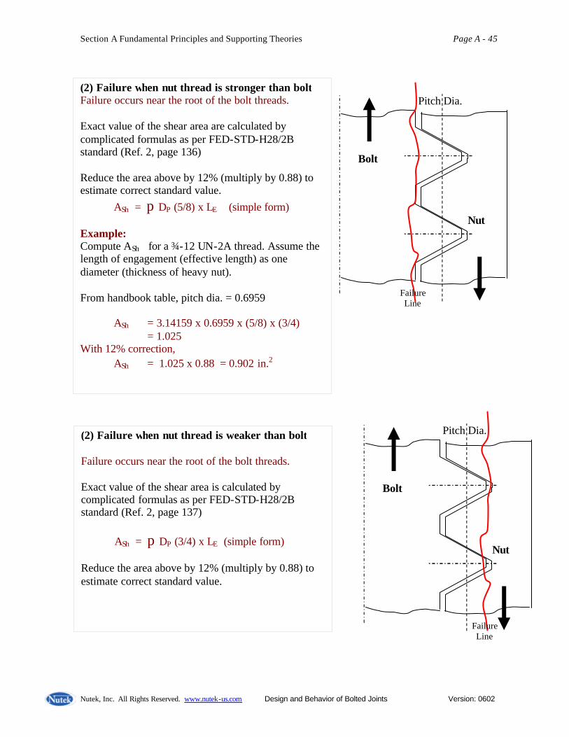
(2) Failure when nut thread is stronger than bolt Failure occurs near the root of the bolt threads. Exact value of the shear area are calculated by complicated formulas as per FED-STD-H28/2B standard (Ref. 2, page 136) Reduce the area above by 12% (multiply by 0.88) to estimate correct standard value. ASh = p DP (5/8) x LE (simple form) Example: Compute ASh for a ¾-12 UN-2A thread. Assume the length of engagement (effective length) as one diameter (thickness of heavy nut). From handbook table, pitch dia. = 0.6959
ASh = 3.14159 x 0.6959 x (5/8) x (3/4) = 1.025 With 12% correction, ASh = 1.025 x 0.88 = 0.902 in.2
Bolt
Nut
Pitch Dia.
Failure Line
Bolt
Nut
Pitch Dia.
Failure Line
(2) Failure when nut thread is weaker than bolt Failure occurs near the root of the bolt threads. Exact value of the shear area is calculated by complicated formulas as per FED-STD-H28/2B standard (Ref. 2, page 137)
ASh = p DP (3/4) x LE (simple form) Reduce the area above by 12% (multiply by 0.88) to estimate correct standard value.
Section A Fundamental Principles and Supporting Theories Page A - 46
Nutek, Inc. All Rights Reserved. www.nutek-us.com Design and Behavior of Bolted Joints Version: 0602
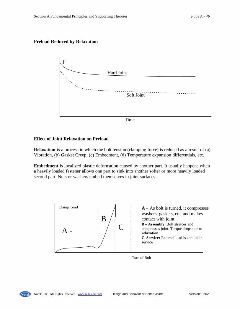
Preload Reduced by Relaxation Effect of Joint Relaxation on Preload Relaxation is a process in which the bolt tension (clamping force) is reduced as a result of (a) Vibration, (b) Gasket Creep, (c) Embedment, (d) Temperature expansion differentials, etc. Embedment is localized plastic deformation caused by another part. It usually happens when a heavily loaded fastener allows one part to sink into another softer or more heavily loaded second part. Nuts or washers embed themselves in joint surfaces.
F
Hard Joint
Soft Joint
Time
Turn of Bolt
Clamp Load
A - B
C
A – As bolt is turned, it compresses washers, gaskets, etc. and makes contact with joint B – Assembly: Bolt stretces and compresses joint. Torque drops due to relaxation. C- Service: External load is applied in service

Section A Fundamental Principles and Supporting Theories Page A - 47
Nutek, Inc. All Rights Reserved. www.nutek-us.com Design and Behavior of Bolted Joints Version: 0602
Relaxation takes place throughout the entire life of joints. Depending on the time of occurrences, it is called short, mid, or log-term relaxation. The causes of relaxation are as shown below. (10 –20 % relaxation is common)
Causes of Relaxation
Thread geometry and contact
Clamp Load
Time
SHORT –TERM • Embedment • Oversized holes • Bending • Softer parts • Nonperpendicularity • Gasket • Fillets on undersized
holes
RELAXATION – Loss of Torque/load
MID–TERM • Corrosion • External Load • Temperature effects
LONG–TERM • Stress Relaxation
Oversized Fillet and Undersized Hole Oversized Hole, Excessive Brinnelling
Section A Fundamental Principles and Supporting Theories Page A - 48
Nutek, Inc. All Rights Reserved. www.nutek-us.com Design and Behavior of Bolted Joints Version: 0602
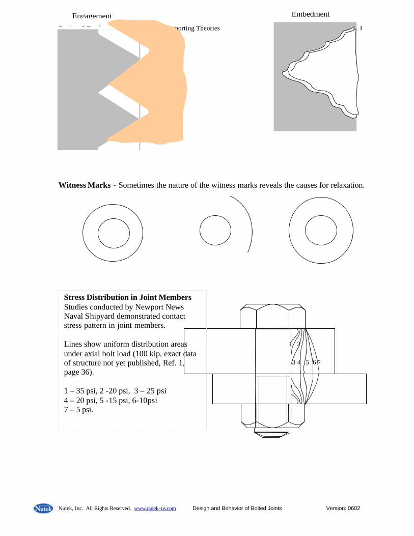
Witness Marks - Sometimes the nature of the witness marks reveals the causes for relaxation.
3 4 5 6 7
1 2
Stress Distribution in Joint Members Studies conducted by Newport News Naval Shipyard demonstrated contact stress pattern in joint members. Lines show uniform distribution areas under axial bolt load (100 kip, exact data of structure not yet published, Ref. 1, page 36). 1 – 35 psi, 2 -20 psi, 3 – 25 psi 4 – 20 psi, 5 -15 psi, 6-10psi 7 – 5 psi.
Embedment Engagement
Section A Fundamental Principles and Supporting Theories Page A - 49
Nutek, Inc. All Rights Reserved. www.nutek-us.com Design and Behavior of Bolted Joints Version: 0602
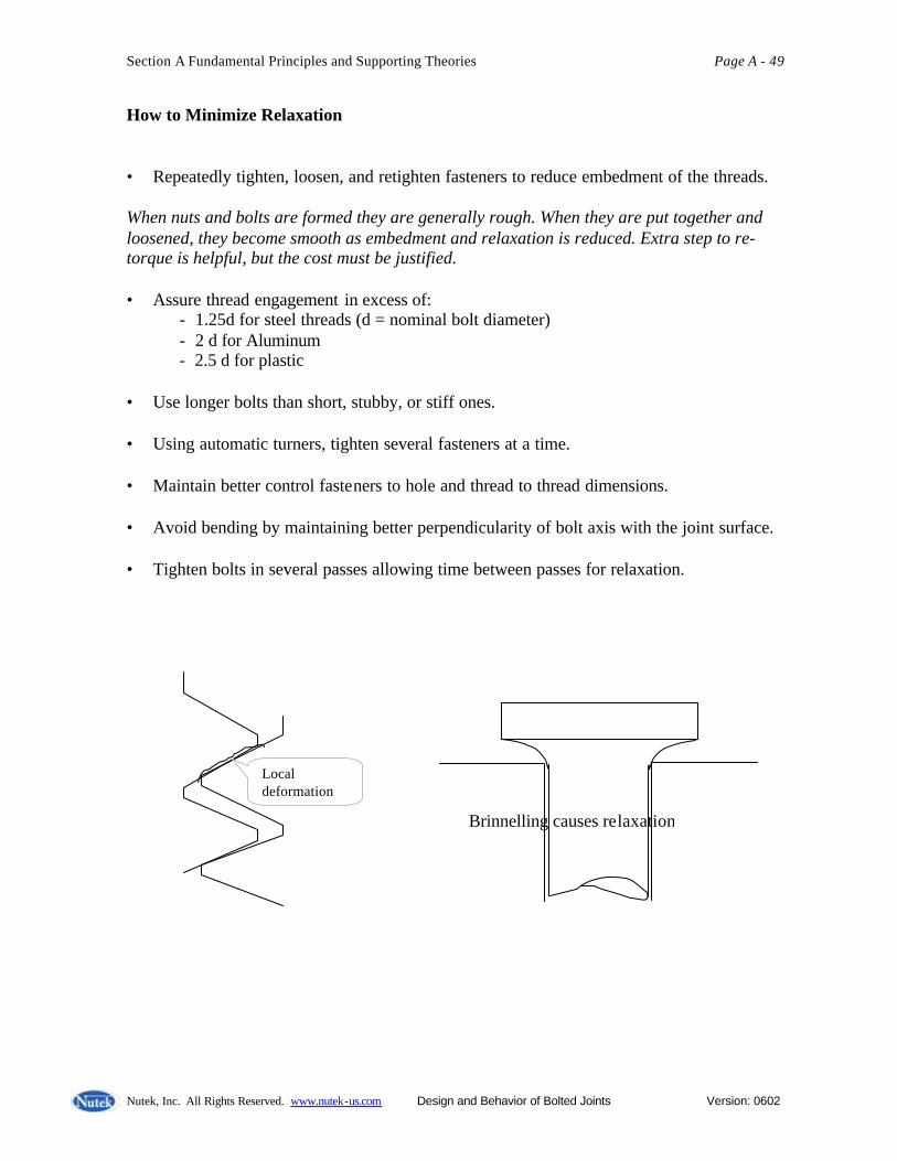
How to Minimize Relaxation • Repeatedly tighten, loosen, and retighten fasteners to reduce embedment of the threads. When nuts and bolts are formed they are generally rough. When they are put together and loosened, they become smooth as embedment and relaxation is reduced. Extra step to re-torque is helpful, but the cost must be justified. • Assure thread engagement in excess of:
- 1.25d for steel threads (d = nominal bolt diameter) - 2 d for Aluminum - 2.5 d for plastic
• Use longer bolts than short, stubby, or stiff ones. • Using automatic turners, tighten several fasteners at a time. • Maintain better control fasteners to hole and thread to thread dimensions. • Avoid bending by maintaining better perpendicularity of bolt axis with the joint surface. • Tighten bolts in several passes allowing time between passes for relaxation.
Local deformation
Brinnelling causes relaxation

Section A Fundamental Principles and Supporting Theories Page A - 50
Nutek, Inc. All Rights Reserved. www.nutek-us.com Design and Behavior of Bolted Joints Version: 0602
Bolt stretch and load For a given diameter, shape, and load, a longer bolt will stretch more than a shorter one. This means that for a computed preload, the stretch will be a function of the Grip Length (usually thickness of the joint members). For a longer bolt, more stretch will be needed to generate the same load.
Stretch (Elongation) ∆L = F L/(AE) since F/A = E ∆L / L For a bolt twice as long, the stretch needed will be twice as much. Longer bolts are advantageous in terms of loss of load due to relaxation.
Grip Length
Section A Fundamental Principles and Supporting Theories Page A - 51
Nutek, Inc. All Rights Reserved. www.nutek-us.com Design and Behavior of Bolted Joints Version: 0602
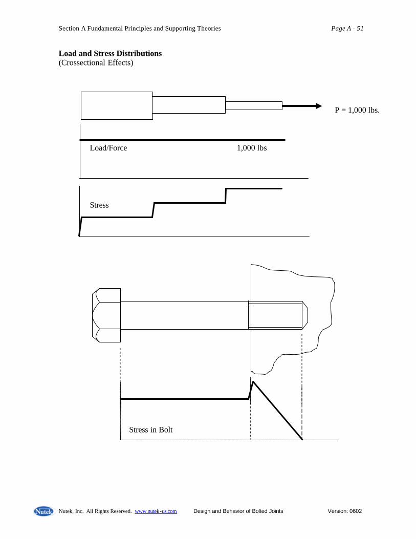
Load and Stress Distributions (Crossectional Effects)
P = 1,000 lbs. Load/Force 1,000 lbs Stress
Stress in Bolt

Section A Fundamental Principles and Supporting Theories Page A - 52
Nutek, Inc. All Rights Reserved. www.nutek-us.com Design and Behavior of Bolted Joints Version: 0602
Thermal Effect on Bolt Tension
When there is change in temperature (say rise), both bolt and the joint members will
change in length. If bolt and the joint members are of different materials, there will be a difference in the thermal expansion resulting in additional bolt load.
Bolt – Steel Joint members – Aluminum
Expansion of Joint members ∆LJ = αJ LJ T Expansion of Bolt ∆LB = αB LB T For a change of temperature T. If ∆LJ > ∆LB then the force developed in the bolt due to temperature effect is Fadl. = (∆LJ - ∆LB ) AB EB / LB Example : Steel Bolt and Aluminum Joint: T = 50 Degree F., LB = 6 in. LJ = 5.5 in. Bolt properties: A = 0.8 in2, E = 30x106 psi. ∆LB = 6.5 x 10-6 x 6 x 50 = 1.95 x 10⁻³
LB
LJ Coefficient of Thermal Expansion αJ = 12.8 x 10⁻⁶ for Aluminum joint αB = 6.5 x 10⁻⁶ for Steel bolt α = 8.4 x 10⁻⁶ for Stainless Steel at room temperature

Section A Fundamental Principles and Supporting Theories Page A - 53
Nutek, Inc. All Rights Reserved. www.nutek-us.com Design and Behavior of Bolted Joints Version: 0602
∆LJ = 12.8 x 10-6 x 5.5 x 50 = 3.52 x 10⁻³ Fadl. = (3.52 x 10⁻³- 1.95 x 10-3) x 0.8 x 30x106 /6.0 = 6,280 lbs. What happens when preload is incorrect? Fastener Failure – If preload is excessive faster may fail by body separation or thread stripping. Joint Member Failure – Excessive preload may cause joint member to crush, warp, gall, or fracture. Fatigue Failure of Bolt – Higher preload enhances the chance of bolt failure by fatigue under externally applied cyclic loading. Joint Separation – Low preload may cause joint to separate and initiate leakage. (Example: fluid in a pipeline, combustion product in engine, etc.) Weight and Cost – Insufficient preload forces a design to have a larger number of fasteners which increases cost and weight. Loosening of nut due to Vibration – Inadequate preload causes loosening of nut. Slippage of Joint members - Slip of joint member may cause misalignment of joint members. FACTORS THAT AFFECT PRELOAD BY TIGHTENING THE BOLT Tool Accuracy – Operator Skill – Parameter Control – The accuracy of control of specified parameters such as Torque, turn, threshold toque, etc. Short Term Relaxation – Long Term Relaxation – Thermal Effects – External Loads – External Loads – Quality of Parts – etc.
Section A Fundamental Principles and Supporting Theories Page A - 54
Nutek, Inc. All Rights Reserved. www.nutek-us.com Design and Behavior of Bolted Joints Version: 0602
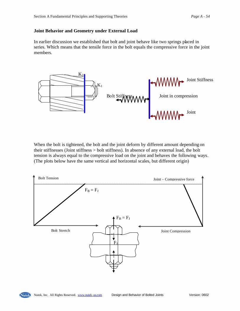
Joint Behavior and Geometry under External Load In earlier discussion we established that bolt and joint behave like two springs placed in series. Which means that the tensile force in the bolt equals the compressive force in the joint members. When the bolt is tightened, the bolt and the joint deform by different amount depending on their stiffnesses (Joint stiffness > bolt stiffness). In absence of any external load, the bolt tension is always equal to the compressive load on the joint and behaves the following ways. (The plots below have the same vertical and horizontal scales, but different origin)
FJ
FB = FJ
Joint Compression
Joint – Compressive force
Bolt Stretch
Bolt Tension
FB = FJ
K2 Joint Stiffness K1 Bolt Stiffness Joint in compression
Joint

Section A Fundamental Principles and Supporting Theories Page A - 55
Nutek, Inc. All Rights Reserved. www.nutek-us.com Design and Behavior of Bolted Joints Version: 0602
When external load of amount Fext is applied to the bolt, the bolt stretches and joint deformation can be drawn in a graph adjacent to each other when stiffness values are known. How is the joint stiffness determined? While bolt stiffness is easily calculated from the material properties and standard bolt geometry, this cannot be easily done for the joint. The joint of interest is very specific and its geometry (stressed area) may be difficult to determine. However, the joint stiffness can be calculated from experimentally determined torque and turn data discussed later in this course. When stiffness values of bolt and joint are known, the above diagram can be drawn to scale for any value of the preload and some key questions can be answered from the diagram or calculated using the formulas shown below. Key questions: What is the additional extension of bolt under external load? At what external load will the joint separate from the bolt?
∆LB ∆LJ
X
FB = FJ
∆FB
∆FJ =
Fext = ∆FB + ∆FJ
External load
No external load
Fcrit = ∆FB + ∆FJ
zero joint load
Load Bolt/Joint
==è Bolt Stretch Joint Compression ç===

Section A Fundamental Principles and Supporting Theories Page A - 56
Nutek, Inc. All Rights Reserved. www.nutek-us.com Design and Behavior of Bolted Joints Version: 0602
Example: Bolt stiffness, KB = 200 x 103 lbs/in. Joint stiffness, KJ = 600 x 103 lbs/in. Preload in the bolt, FB = 8,000 lbs. Fext. = 4,000 lbs. Analytical Solution: Bolt extension due to external load, X = 4,000 x 10-3 / (200 + 600) = 5 x 10⁻³ in. Critical load, Fcrit. = FB (1 + KB / KJ ) = 8,000 (1 + 200/600) = 10,640 lbs. Graphical Solution: Step1. Select a graph paper with vertical and horizontal gr id lines. Select origin at O and draw axes OY and OB. Step 2. Select a suitable scale such as Y-axis: 2,000 lbs/unit, X-axis: 5 x10⁻³ in/unit. Step 3. From given bolt load (equals joint load), calculate
Bolt stretch = 8,000/(200 x 103 ) = 40 x10-3 in. which is 8 units along X-axis. Draw line OA with A 8 units to the right from O.
Step 4. Identify point C 4 units above point A as the 8,000 lbs bolt load. Draw a line to join point O to C to represent bolt stiffness.
Additional stretch on bolt due to external load Fext on the bolt head. ∆FB = KB X = Fext. [KB /( KB + KJ) ] Since ∆FB = KB X and ∆FJ = KJ X Fext. = ∆FB + ∆FJ = X ( KB + KJ) Or X = Fext. /( KB + KJ) Note: ∆FJ is the reduction of compressive load in the joint which must be overcome by the external load before increasing the load on bolt.
External load (Fext = Fcrit ) needed to create separation between bolt head and the joint surface (zero joint load). Fcrit = FB + ∆FB (at zero joint load) Also, ∆FB(at zero joint load) = KB ∆LJ = KB (FB/KJ ) Fcrit. = FB + KB (FB/KJ ) = FB (1 + KB / KJ ) Note: KB ∆LJ is load necessary to stretch the bolt by the amount joint compression before external load is applied.

Section A Fundamental Principles and Supporting Theories Page A - 57
Nutek, Inc. All Rights Reserved. www.nutek-us.com Design and Behavior of Bolted Joints Version: 0602
Step 5. Calculate
Joint compression = 8,000/(600 x 103 ) = 13.33 x10⁻³ in.
which is 2.67 units to the right of A along X-axis. Mark this point as B and join B and A. Pont B represent the origin of joint load-compression plot.
Step 6. Extend line OC to point F and beyond. Step 7. Prepare a vertical line of 2 units in length that represents 4,000 lbs of external load as shown at top right in the diagram below. Step 9. Slide this line toward point C while keeping it vertical at all times until it touches line OF at D and line BC at E. Measure distance CG (1 unit = 5 x 10⁻³ in ) as the additional bolt stretch due to external load, DE. Step 10. Draw a vertical line from point B. Let this line intersect bolt stiffness line OF at F. The vertical distance BF (5.3 units = 10,600 lbs) now represents the critical external load. Below are a few additional information you can obtain from the plot: a. Total bolt stretch under 4,000 lbs. external load is OH = 9 units or 45 x 10-3 in. b. Total bolt load when 4,000 lbs. external load is DH = 4.5 units or 9,000 lbs. c. Bolt load is the same as the external load when it reaches the critical load limit (BF).
Scale: Y-axis: 2,000 lbs/unit, X-axis: 5 x10⁻³ in/unit
External Load
F-Critical
4,000 lbs
o A
Load F
C
B
D
E
AC = Bolt Load, OA = Bolt Stretch, AB= Joint Comp., DE = External load, BF = Critical load
Y
G
H

Section A Fundamental Principles and Supporting Theories Page A - 58
Nutek, Inc. All Rights Reserved. www.nutek-us.com Design and Behavior of Bolted Joints Version: 0602
Summary: Bolt Strength Information
Strength of a Bolt
• Proof Load – point just before any permanent deformation
• Tensile or Yield Strength –load at o.20 to 0.5% strain
• Ultimate Strength – maximum load without rupture
Proof < Yield < Ultimate
Tensile Stress Area Tensile stress area of a bolt is used to calculate proof, tensile or yield strength of bolts. It is also used to calculate nominal tensile stress under a load. Most common formula for tensile stress area is:
As = 0.785 (D – 0.9743/N )2 sq. in. Where D = Nominal diameter of bolt N = Number of threads per inch (TPI)
Contact Stresses
• Washers help avoid embedment and stress distribution. Thicker & harder washers are better.
• Stress variation along the bolt of 8:1 is common.
• Bolt to bolt stress variation depends on spacing and sequence of tightening.
Bolt Stress Contour
.
• Stress under nut may exceed yield strength.
Static Strength of a Bolt • Calculated bolt strength indicates
available clamping force. • Proof load is the maximum usable
strength of a bolt. • Bolt breaks in one of four ways :
o Bolt body breaks at a stress concentration point
o Bolt threads strips (thread shear failure)
o Nut threads could strip (uncommon)
o Bolt and thread strip together
Static Strength Computation Find yield strength for ¼ -20 UNC class 2A Inconel 600 Bolt (ambient yield stress from table). s = 37,00 psi.
As = 0.785 (D – 0.9743/n )2 = 0.0318 F = 37,000 x 0.0318 = 1,178 lbs.
Section A Fundamental Principles and Supporting Theories Page A - 59
Nutek, Inc. All Rights Reserved. www.nutek-us.com Design and Behavior of Bolted Joints Version: 0602
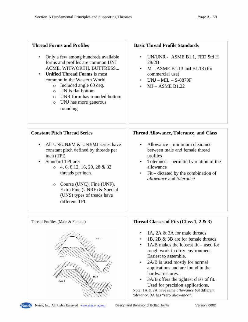
Thread Forms and Profiles
• Only a few among hundreds available forms and profiles are common UNJ ACME, WITWORTH, BUTTRESS...
• Unified Thread Forms is most common in the Western World
o Included angle 60 deg. o UN is flat bottom o UNR form has rounded bottom o UNJ has more generous
rounding
Basic Thread Profile Standards
• UN/UNR - ASME B1.1, FED Std H 28/2B
• M – ASME B1.13 and B1.18 (for commercial use)
• UNJ – MIL – S-8879F • MJ – ASME B1.22
Thread Profiles (Male & Female) Thread Classes of Fits (Class 1, 2 & 3)
• 1A, 2A & 3A for male threads • 1B, 2B & 3B are for female threads • 1A/B makes the loosest fit – used for
rough work in dirty environment. Easiest to assemble.
• 2A/B is used mostly for normal applications and are found in the hardware stores.
• 3A/B offers the tightest class of fit. Used for precision applications.
Note: 1A & 2A have same allowance but different tolerance. 3A has “zero allowance”.
Constant Pitch Thread Series
• All UN/UNJ/M & UNJ/MJ series have constant pitch defined by threads per inch (TPI)
• Standard TPI are: o 4, 6, 8,12, 16, 20, 28 & 32
threads per inch.
o Course (UNC), Fine (UNF), Extra Fine (UNRF) & Special (UNS) types of treads have different TPI.
Thread Allowance, Tolerance, and Class
• Allowance – minimum clearance between male and female thread profiles
• Tolerance – permitted variation of the allowance
• Fit – dictated by the combination of allowance and tolerance
Section A Fundamental Principles and Supporting Theories Page A - 60
Nutek, Inc. All Rights Reserved. www.nutek-us.com Design and Behavior of Bolted Joints Version: 0602
Topics Group Exercises
Equivalent Stiffness
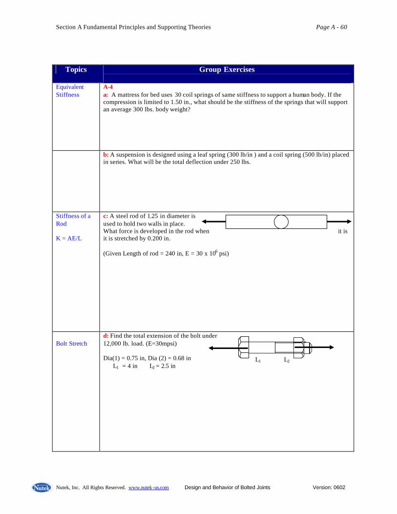
A-4 a: A mattress for bed uses 30 coil springs of same stiffness to support a human body. If the compression is limited to 1.50 in., what should be the stiffness of the springs that will support an average 300 lbs. body weight?
b: A suspension is designed using a leaf spring (300 lb/in ) and a coil spring (500 lb/in) placed in series. What will be the total deflection under 250 lbs.
Stiffness of a Rod K = AE/L
c: A steel rod of 1.25 in diameter is used to hold two walls in place. What force is developed in the rod when it is it is stretched by 0.200 in. (Given Length of rod = 240 in, E = 30 x 106 psi)
Bolt Stretch
d: Find the total extension of the bolt under 12,000 lb. load. (E=30mpsi) Dia(1) = 0.75 in, Dia (2) = 0.68 in L1 = 4 in L2 = 2.5 in
L1 L2

Section A Fundamental Principles and Supporting Theories Page A - 61
Nutek, Inc. All Rights Reserved. www.nutek-us.com Design and Behavior of Bolted Joints Version: 0602
Topics Group Exercises
Axial and Bending Stresses Ix = ? D4/64 J = ?D4/32 s b = M (D/2)/I t t = T (D/2)/J
A-5 a: Find the maximum tensile stress in the upper fiber of the rod subjected to the bending and axial forces as shown.
A = ? D2/4 P = A x Stress
b: Four bolts are used to attach a plate used to lift a machine weighing 350,000 lbs. Based on axial loading, what should be the minimum diameter of the bolts made of materials with stress limit of 45,000 psi?
Strength of Materials
Shear Stress
c: Find minimum number of thread engagement of bolt required to avoid thread shear. Design strategy: Shear capacity exceeds tensile load Bolt dia. = 1.00 in, Pitch dia =0.85 in, Pitch = 0.078 in. Max. tensile stress = 30,000 psi, max. shear stress = ½ Tensile stress Use thread shear area/turn = ? (Pitch dia) x Pitch
Bolt Strength Calculation
A-6 Calculated the proof load and rupture strength of a 1 - 8 UNC 2A bolt made of steel with yield stress = 35ksi. Assume that the rupture point of this material is 1.5 times the yield point. Hint: Calculate stress areas of bolt using the formula As = 0.785 (D – 0.9743/n )2
2,000 lbs.

Section – B
Bolted Joint Design Strategies and Assembly Considerations Torque and Tension Relationship T = FR r The bolt head is turned by use of a wrench. Force (FR ) applied on the wrench handle at a distance (r) from the center of the bolt head produces a torque T. As the applied torque turns the bolt thread, the engaged threaded portion of the bolt pulls the bolt to the right (Figure at right above, one thread pitch distance each turn). Once the bolt head touches the joint surface, it prevents the bolt from sinking into the surface. Additional torque from this point onward is resisted by bolt (I) stretch, which produced tensile load (clamping force or preload) in the body of the bolt. As the tensile load is generated in the bolt, the friction forces at the contact points, (II) between bolt head and the joint surface, and (III) between the bolt and the joint threads, also increase proportionally. In other word, the applied torque (T) is required to overcome resisting torque arising from: (I) Bolt stretch, one thread pitch for every turn (TP) (II) Frictional resistance between the contacting threads(TT) (III) Frictional drag between bolt head (or washer) and joint surface(TB)
FR
r
T
Joint member in compression
F

Section B Bolted Joint Design Strategies Page B - 2
Nutek, Inc. All Rights Reserved. www.nutek-us.com Design and Behavior of Bolted Joints Version: 0602
Thus T = TP + TB + TT Torque necessary to overcome thread pitch
(Ignoring friction for the time being) In case of a transational force in a system shown at right, the force F Necessary to push the body up (force P is appliedon the body), can be be easily found by considering the conservation of energy. Work done to push the body over a distance S is same as the increase in the energy in lifting the body by a height H against the force P. That is F S = P H, or F = P (H/S) Likewise, for a rotational motion, as in one turn of the thread of the bolt, P = Thread pitch (distance in one turn) F = Force in the bolt (tension/clamping force) TP = Torque required to overcome pitch (cause bolt stretch by pitch distance) Energy spent to complete one turn (angle 2Π) by applying torque is 2Π TP . Work done in stretching the bolt by a distance P against the force F is FxP. Thus, 2Π TP = FxP or TP = F (P/2Π )
F
P
H S
At start of a turn
After one turn, F is raised by P.

Section B Bolted Joint Design Strategies Page B - 3
Nutek, Inc. All Rights Reserved. www.nutek-us.com Design and Behavior of Bolted Joints Version: 0602
(II) Torque necessary to overcome thread friction Frictional drag is proportional to the force normal to the thread surface. A component of the force normal to the surface (FN) resists the bolt force (F). FN = F / Cos α Friction force between thread which resists the motion is µT x FN. µT = Friction coefficient between threads rT = Effective radius of thread α = Half thread angle TT = µT FN. rT = F µT rT /(Cos α) Or
TT = F µT rT /(Cos α ) (III) Torque necessary to overcome bolt head/washer friction (TB)
(Bearing Component) µB = Bearing surface Friction coefficient rB = Effective bearing radius Friction force at bearing surface is µB xF. Therefore, the torque necessary to overcome the bearing friction is TB = µB F rB Or TB = F µB rB
α
Fα FN
rT
TB TB
Bearing Surface area

Section B Bolted Joint Design Strategies Page B - 4
Nutek, Inc. All Rights Reserved. www.nutek-us.com Design and Behavior of Bolted Joints Version: 0602
Since T = TP + TB + TT
T = F [ P/(2Π ) + µT rT /(Cos α ) + µB rB] Where
T = Toque applied to the bolt F = Force in the bolt (tension/clamping force) P = Thread pitch (distance in one turn) µT = Friction coefficient between threads rT = Effective radius of thread α = Half thread angle µB = Bearing surface Friction coefficient rB = Effective bearing radius The equation above shows that the input torque (T) is resisted by three reaction torques: F P/(2Π ) - 10% (shown next) Is produced by the inclined thread plane or bolt thread on joint (or nut). This is generally called the bolt stetch component. F µT rT /(Cos α ) - 40% Is a reaction torque due to friction between the threads? F µB rB - 50% Is the reaction torque generated by the friction between the bolt head/nut and the washer or the joint?

Section B Bolted Joint Design Strategies Page B - 5
Nutek, Inc. All Rights Reserved. www.nutek-us.com Design and Behavior of Bolted Joints Version: 0602
The ratio of T/F can be calculated for a Bolt as T /F = [ P/(2Π ) + µT rT /(Cos α ) + µB rB] = [ 1/(13x2Π ) + 0.15x0.225 /(Cos 30) + 0.15x0.32] = 0.0122 + 0.039 + 0.048 = 0.099 Percentage of torque used to overcome the Resisting torques are as follows. 0.0122/0.099 = 12 %, due to pitch (≅10%) 0.039/0.099 = 39% due to thread (≅ 40%) 0.049/0.099 = 49% due to bearing (≅50%) In addition to torque required to tighten the bolt, there could be torque required to run down the bolt/nut against interference or inserts. These kinds of reaction torque are called prevailing torque (TP). Example : The torque required to run down a lock nut which has a plastic insert in the thread. With the prevailing torque included, the torque equation will be: T = F [ P/(2Π ) + µT rT /(Cos α ) + µB rB] + TP In many common situation the prevailing toque is absent, TP = 0.
Example data 1/2 - 13 UNC Thread T = Toque applied F = One unit ( =1) P = 1/13 inch µT = 0.15 rT = 0.225 inch α = 30 o
µB = 0.15 rB = 0.32 inch
40% Thread
50% Bearing
10% Pitch
Total Torque Breakdown
Section B Bolted Joint Design Strategies Page B - 6
Nutek, Inc. All Rights Reserved. www.nutek-us.com Design and Behavior of Bolted Joints Version: 0602
The Short-Form of Torque vs. Tension Relation A close examination of the torque vs. tension equation shows that thread pitch, P, radii rT and rB are all dependent on the nominal diameter (D) of the bolt. Furthermore, the friction coefficients are also constant for the material. Thus, T = F [ P/(2Π) + µT rT /(Cos α) + µB rB] = F [ K1 D + K2 D + K3 D] = F D [ K1 + K2 + K3 ] or T = K D F Where T = Input torque on the bolt or nut (in- lb. or N-mm) F = Tension in the bolt (lb. or N) D = Nominal diameter of the bolt (in. or mm) K = Constant called “Nut Factor” (dimensionless, no units) K1, K2, and K3 are also constants and K= K1 + K2 + K3 The Nut Factor K is a general-purpose, experimentally determined constant. It
- is not a coefficient of friction (friction has influence) - is anything and everything that affect the relationship between torque and tension in the experiment – including friction, torsion, bending, plastic deformation of threads, etc. - can only be determined experimentally by testing a number of samples.
T = K D F is a simple equation and K, the Nut Factor is an all inclusive constant which captures effects of all that affect torque-tension relationship. Prescribing a torque (T) that is needed to achieve a certain tension (F) will have been a simple matter if only K had a unique value for each application. Unfortunately, the Nut Factor varies widely from sample to sample for the same application.

Section B Bolted Joint Design Strategies Page B - 7
Nutek, Inc. All Rights Reserved. www.nutek-us.com Design and Behavior of Bolted Joints Version: 0602
Graph below shows the Histogram of K values reported for as-received steel fasteners from a large number of sources. Because of the associated variability, the Nut Factor is defined in terms of a mean value and the scatter. Available experimental data for various materials, procedures, lubricants, types of tool, etc. provide a guideline for design specification. The exact value of K, however, must be determined experimentally using the production application setup.
0.153 0.178 0.203 0.228 0.253 Nut Factor (K)
Probability 15% 10% 5%
Nut Factor (K) Fastener Materials & Coatings Min. Val. Mean Max. Pure aluminum coating on AISI 8740 alloy steel 0.42 0.52 0.62 As received, mild or alloy steel on steel 0.158 0.20 0.267 Machine Oil 0.04 ------ 0.18 Zinc plate (Waxed) 0.071 0.288 0.52 Zinc plate (dry) 0.075 0.295 0.53
Section B Bolted Joint Design Strategies Page B - 8
Nutek, Inc. All Rights Reserved. www.nutek-us.com Design and Behavior of Bolted Joints Version: 0602
Uncertainty in Assembly Caused by Variability in Nut factor (K) Automatic nut turner can accurately apply the specified torque during assembly operations (1 –2% accuracy for electric turner). But whether the specified torque will produce the desired bolt tension will depend on the Nut factor (K). As the Nut Factor vary sample to sample, the tension obtained will also vary. As seen with reported experimental results, the range of variability (Max. – Min value) may be several times that of the mean value. Values of K for Zinc plate (dry) Min. = 0.075 Mean =0.295 Max = 0.53 Since T = K D F F = T / (K D) If a fixed toque T= 1000 in- lb. Is applied on an 1 inch diameter bolt, then the force obtained may be different depending on the value of K as shown below. High F = 1,000/ (1 x 0.075) = 13, 333 lbs. (With low K) Mean F = 1,000 / (1 x 0.295) = 3,389 lbs. Low F = 1,000 / (1 x 0.53) = 1,886 lbs. (With high K) Observations: 1. Can the bolt withstand the high load? Will it yield or fracture? 2. Is the low load enough for the desired clamp load? Will the joint loosen? 3. What percent will have low load? What percent will fail? If we were to calculate the toque necessary to obtain a fixed F= 5,000 lb. instead, then the torque necessary will widely vary. Using T = K D F Low T = 0.075 x 1 x 5,000 = 375 in- lb. Mean T = 0.295x 1 x 5,000 = 1,475 in- lb. High T = 0.53 x 1 x 5,000 = 2,650 in- lb. (In assembly operation, torque is never varied/adjusted from sample to sample)

Section B Bolted Joint Design Strategies Page B - 9
Nutek, Inc. All Rights Reserved. www.nutek-us.com Design and Behavior of Bolted Joints Version: 0602
Topics Group Exercises – B
Torque Breakdown
B-1 a: In an assembly, the torque required to tighten the bolted joint is 500 in.lb. How much torque would be reduced, if the frictional resistance between the nut/bolt-head and the joint is fully eliminated by some means? (Hint use the standard breakdown)
Torque Vs. Tension
b: The bolt of type shown at right is subjected to a torque, T = 1,200 in. lb. What is the expected tension (F) produced in the bolt. Hint: T = [ P/(2Π ) + µT rT /(Cos α ) + µB rB] F (Ans: F = 12,121 lbs.)
c: If the friction under the bearing surface in the above example is reduced to one third the original value (µB = 0.05), what will be the increased bolt tension when the same torque is applied.
d: If the friction between the contacting threads in problem B-1b above is increased to twice the original value (µT = 0.3.0), what will be the reduced value of the bolt tension when the same torque is applied.
Bolt Data 1/2 - 13 UNC Thread T = Toque applied F = One unit ( =1) P = 1/13 inch µT = 0.15 rT = 0.225 inch α = 30 o
µB = 0.15 rB = 0.32 inch

Section B Bolted Joint Design Strategies Page B - 10
Nutek, Inc. All Rights Reserved. www.nutek-us.com Design and Behavior of Bolted Joints Version: 0602
Topics Group Exercises – B
Nut factor
B-2 a: The experimentally determined distribution of the Nut Factor for a joint assembly is found to have Avg: 0.30 with Standard deviation = 0.07. If a fixed torque of 800 lb. in. is applied to a ¾ in dia bolt, what will be the expected minimum and maximum values of the force in the bolt? (Hint: Use F = T/(KD), Kmin = avg – 3 Std.Dev. etc., Ans: Fmax= 11,851/Fmin= 2,091 )
Torque vs. Tension Relationship T = KDF F = T/(KD)
b: The measured value of the tension (F) after assembly of a ¾ in dia. bolt was found to be 3,500 lbs. What would the tension value be if the nut factor is reduced to half its value when the same torque is applied?
F = T/(KD)
c: In an assembly is designed to apply a torque (T) to generate a desired tension (F). If the bolt is replaced by another bolt of the same type and material, but 20% larger in diameter, show that this action will reduce the bolt tension by 20%. (Assume that the nut factor is the same)
K = T / (DF)
d: Values of torque and tension measured in the ½ in dia. bolt after assembly are: T = 80 lb.in. & F = 1,800 lbs. What is the expected value of the nut factor (K)?

Section B Bolted Joint Design Strategies Page B - 11
Nutek, Inc. All Rights Reserved. www.nutek-us.com Design and Behavior of Bolted Joints Version: 0602
Factors That Affect Tension Variability Given a design, the Nut Factor (hence the torque necessary for a fixed tension) will vary because of the following.
Book Values of K Mild or alloy steel on steel 0.158 - 0.2 - 0.267 Pure aluminum, coated 0.420 - 0.52 - 0.62 Everlube coated threads 0.069 - 0.086 - 0.103 Fel-pro C54 0.080 - 0.132 - 0.230 Ref: Bickford[2], pp.141.
FOGTAR A word meaning TROUBLE
in Tibetan language. Ref: John H. Bickford
Friction Operator Geometry Tool Accuracy Relaxation
Materials and Design factors • type of materials • hardness • surface finish • plating/coating • lubricants • hole clearance • contact radii • thread pitch • flatness • perpendicularity
Manufacturing Factors • Tool accuracy • Operator skill • Control accuracy • Part quality Operating Environment • Corrosion • relaxation • Gaskets • Vibration • Temperature • External load
Misc. Factors • Blind holes • Dirt • Chips • Cross-threads • Burrs • Wrong size bold • Metric/English • Cleaning agent • Deformed threads • Insufficient thread
depth

Section B Bolted Joint Design Strategies Page B - 12
Nutek, Inc. All Rights Reserved. www.nutek-us.com Design and Behavior of Bolted Joints Version: 0602
T = K D F Where K = empirically determined constant D = diameter of bolt F = Bolt tension
Also F = T / (K D) Observed in assembly
Hold torque fixed – clamp load will vary Hold clamp load fixed – torque will vary Join Assembly Challenge GOAL – How to reduce the variability of the clamp load in assembly where only the torque can be held accurately. (Tension is what we need, but torque is the only practical thing that can be controlled)
Bolt Tension, F
Applied Torque, T
--------- Ideal behavior ______ Observed behavior
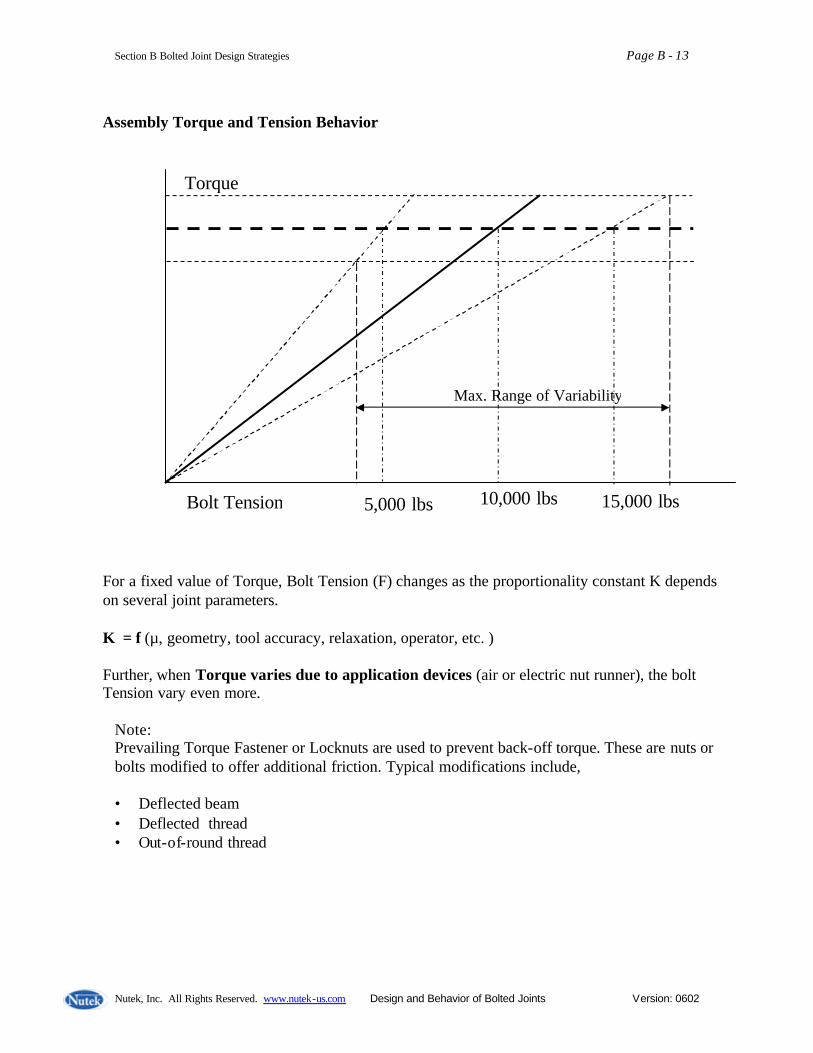
Section B Bolted Joint Design Strategies Page B - 13
Nutek, Inc. All Rights Reserved. www.nutek-us.com Design and Behavior of Bolted Joints Version: 0602
Assembly Torque and Tension Behavior
For a fixed value of Torque, Bolt Tension (F) changes as the proportionality constant K depends on several joint parameters.
K = f (µ, geometry, tool accuracy, relaxation, operator, etc. ) Further, when Torque varies due to application devices (air or electric nut runner), the bolt Tension vary even more.
Note: Prevailing Torque Fastener or Locknuts are used to prevent back-off torque. These are nuts or bolts modified to offer additional friction. Typical modifications include, • Deflected beam • Deflected thread • Out-of-round thread
Torque
5,000 lbs 10,000 lbs 15,000 lbs Bolt Tension
Max. Range of Variability
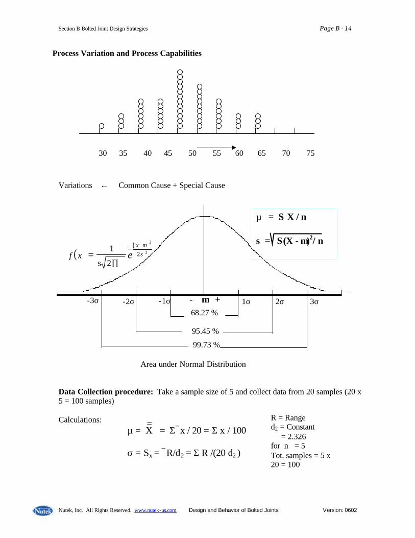
Section B Bolted Joint Design Strategies Page B - 14
Nutek, Inc. All Rights Reserved. www.nutek-us.com Design and Behavior of Bolted Joints Version: 0602
Process Variation and Process Capabilities Variations ← Common Cause + Special Cause
Data Collection procedure: Take a sample size of 5 and collect data from 20 samples (20 x 5 = 100 samples) Calculations:
( )( )
f x ex
=∏
−1
s 2
µσ
2
22
µ = X = Σx / 20 = Σ x / 100 σ = Sx = R/d2 = Σ R /(20 d2 )
= R = Range d2 = Constant = 2.326 for n = 5 Tot. samples = 5 x 20 = 100
99.73 %
95.45 %
68.27 % 1σ -1σ 2σ -2σ 3σ -3σ
Area under Normal Distribution
- µ +
µ = Σ X / n σ = Σ(X - µ)2/ n
30 35 40 45 50 55 60 65 70 75 80

Section B Bolted Joint Design Strategies Page B - 15
Nutek, Inc. All Rights Reserved. www.nutek-us.com Design and Behavior of Bolted Joints Version: 0602
Process Performance Cp = Process Potential and Cpk = Process Capability
LSL = Lower Specification Limit , USL = Upper Specification Limit
Definitions: C p = (USL – LSL)/ 6σ
Cpk = ( )
smaller is whichever3
USLorLSL
σ
µµ −−
µ = average of the population of samples σ = Standard deviation population of samples
Example : µ = 75, σ = 7, LSL = 60, and USL = 100 C p = (100 - 60) / (6 x 7) = 40 / 42 = 0.95 Cpk = (75 – 60) / (3 x 7) = 15 / 21 = 0.71
(µ - LSL) (USL - µ) Target
1σ -1σ 2σ -2σ 3σ -3σ
σ = 4.0
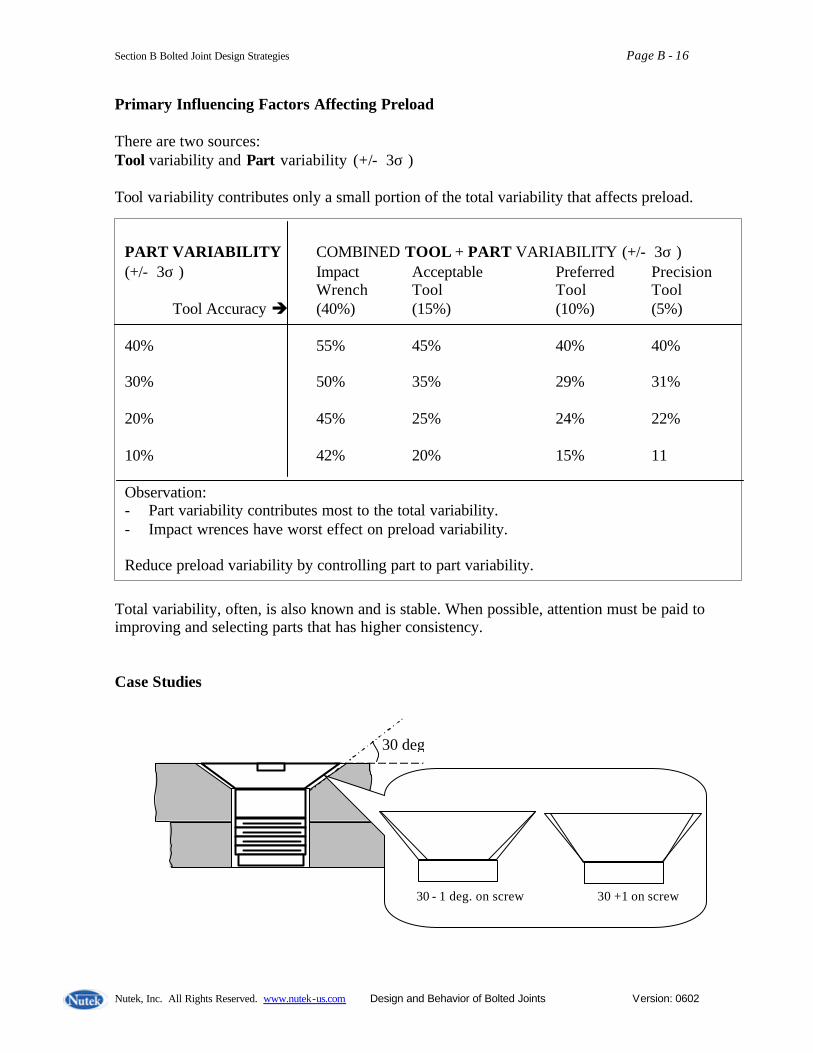
Section B Bolted Joint Design Strategies Page B - 16
Nutek, Inc. All Rights Reserved. www.nutek-us.com Design and Behavior of Bolted Joints Version: 0602
Primary Influencing Factors Affecting Preload There are two sources: Tool variability and Part variability (+/- 3σ ) Tool variability contributes only a small portion of the total variability that affects preload.
Total variability, often, is also known and is stable. When possible, attention must be paid to improving and selecting parts that has higher consistency. Case Studies
PART VARIABILITY COMBINED TOOL + PART VARIABILITY (+/- 3σ ) (+/- 3σ ) Impact Acceptable Preferred Precision Wrench Tool Tool Tool
Tool Accuracy è (40%) (15%) (10%) (5%) 40% 55% 45% 40% 40% 30% 50% 35% 29% 31% 20% 45% 25% 24% 22% 10% 42% 20% 15% 11 Observation: - Part variability contributes most to the total variability. - Impact wrences have worst effect on preload variability. Reduce preload variability by controlling part to part variability.
30 - 1 deg. on screw 30 +1 on screw
30 deg

Section B Bolted Joint Design Strategies Page B - 17
Nutek, Inc. All Rights Reserved. www.nutek-us.com Design and Behavior of Bolted Joints Version: 0602
Torque applied to a bracket piece screw shown above resulted in bi-modal distribution shown below. To avoid bi-modal distribution, tolerance on the screw was changed from 30 +/- 1 to 30 – 2, + 0. These forces contact on the upper rim of the screw head and mean torque at a higher range. Bolt Tightening Strategies Torque Rate (Joint Rate) Soft Joint A joint fastened with a bolt that Takes 720° (2 turns) turn of the bolt to reach the desired torque TT h = Threshold torque Example : Tapping screws, valve cover gasket, Antenna mount, pipe joint, instrument Panel, Hose clamps, Engine mount, etc. Hard Joint A joint where the bolt reaches the desired torque within 36 ° turn (1/10 turn) of the bolt.
Torque
Frequency Bimodal Distribution
Torque T Tth 720 deg Torque
T 36 deg.

Section B Bolted Joint Design Strategies Page B - 18
Nutek, Inc. All Rights Reserved. www.nutek-us.com Design and Behavior of Bolted Joints Version: 0602
Soft joint Relative Hardness of Joints Which among the following joints is hardest?
T / Angle = Joint Stiffness If for a fixed amount of angle (say one turn), the torque required is more, then the stiffness of the joint will be also higher.
T = KDF ( F = axial force, D= diameter, K = constant) Or T = K D (AE/L) P (A = area, E= modulus, P = thread pitch) Or T = K E P (Π /4) D3 /L
Torque T Hard Joint Soft joint Turn/Angle
Length = 2 in. Length = 2 in. Nominal Dia = ½ Nominal Dia = 1 in. Assume that thread pitch and (Material: E = 30 x 106 psi.) is same for all three joints. Length = 4 in.
Nominal Dia. = 1 in
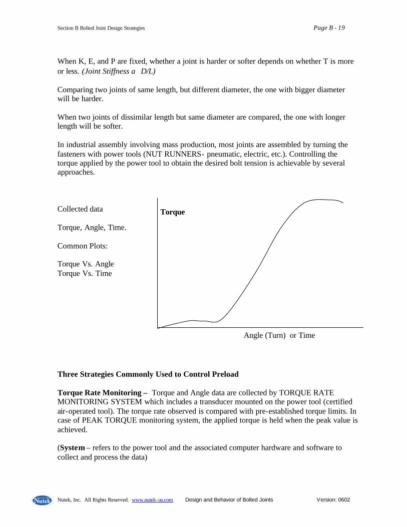
Section B Bolted Joint Design Strategies Page B - 19
Nutek, Inc. All Rights Reserved. www.nutek-us.com Design and Behavior of Bolted Joints Version: 0602
When K, E, and P are fixed, whether a joint is harder or softer depends on whether T is more or less. (Joint Stiffness α D/L) Comparing two joints of same length, but different diameter, the one with bigger diameter will be harder. When two joints of dissimilar length but same diameter are compared, the one with longer length will be softer. In industrial assembly involving mass production, most joints are assembled by turning the fasteners with power tools (NUT RUNNERS- pneumatic, electric, etc.). Controlling the torque applied by the power tool to obtain the desired bolt tension is achievable by several approaches. Collected data Torque, Angle, Time. Common Plots: Torque Vs. Angle Torque Vs. Time Three Strategies Commonly Used to Control Preload Torque Rate Monitoring – Torque and Angle data are collected by TORQUE RATE MONITORING SYSTEM which includes a transducer mounted on the power tool (certified air-operated tool). The torque rate observed is compared with pre-established torque limits. In case of PEAK TORQUE monitoring system, the applied torque is held when the peak value is achieved. (System – refers to the power tool and the associated computer hardware and software to collect and process the data)
Angle (Turn) or Time
Torque
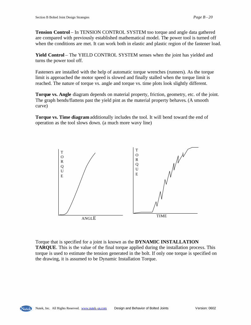
Section B Bolted Joint Design Strategies Page B - 20
Nutek, Inc. All Rights Reserved. www.nutek-us.com Design and Behavior of Bolted Joints Version: 0602
Tension Control – In TENSION CONTROL SYSTEM too torque and angle data gathered are compared with previously established mathematical model. The power tool is turned off when the conditions are met. It can work both in elastic and plastic region of the fastener load. Yield Control – The YIELD CONTROL SYSTEM senses when the joint has yielded and turns the power tool off. Fasteners are installed with the help of automatic torque wrenches (runners). As the torque limit is approached the motor speed is slowed and finally stalled when the torque limit is reached. The nature of torque vs. angle and torque vs. time plots look slightly different. Torque vs. Angle diagram depends on material property, friction, geometry, etc. of the joint. The graph bends/flattens past the yield pint as the material property behaves. (A smooth curve) Torque vs. Time diagram additionally includes the tool. It will bend toward the end of operation as the tool slows down. (a much more wavy line) Torque that is specified for a joint is known as the DYNAMIC INSTALLATION TARQUE. This is the value of the final torque applied during the installation process. This torque is used to estimate the tension generated in the bolt. If only one torque is specified on the drawing, it is assumed to be Dynamic Installation Torque.
TORQUE
ANGLE
TORQUE
TIME

Section B Bolted Joint Design Strategies Page B - 21
Nutek, Inc. All Rights Reserved. www.nutek-us.com Design and Behavior of Bolted Joints Version: 0602
Inspection of Installed Torque The torque measured by turning a fastener (which is already installed) in the tightening direction until it just begins to move is called the STATIC AUDIT TORQUE or BREAKAWAY TORQUE. The torque value falls past the Static Audit Torque, as dynamic friction coefficient is greater than the static value. For quality inspection purposes Static Audit Torque is determined by taking a statistical sample (usually 100).
- Use electronic torque wrenches instead of conventional audit wrenches - Consider relaxation and measure after established time delay
If the fastener is turned beyond its original position, the torque may be increased to a new value called the NEW INSTALLATION TORQUE. Electronic torque wrenches will record this as the highest value.
TORQUE
ANGLE
Dynamic Ins tallation Torque
Slope= Torque Rate = 0.5 N/deg (say) Operator reaction =10 deg. (0.5x10 = 5 N)

Section B Bolted Joint Design Strategies Page B - 22
Nutek, Inc. All Rights Reserved. www.nutek-us.com Design and Behavior of Bolted Joints Version: 0602
The greater of the Static Breakaway Torque and the New Installation Torque is called the RESIDUAL TORQUE. In the above diagram, the new installation torque is the residual torque. Field Observations (a)Torque specified = 45 N Auditor checks the torque to be 52 lbs. (45 + 7 lbs). Recommends lowering of the power tool. Soon finds the joint to be loose.
TORQUE
ANGLE
New Installation Torque
Dynamic Installation Torque
Static Breakaway Torque
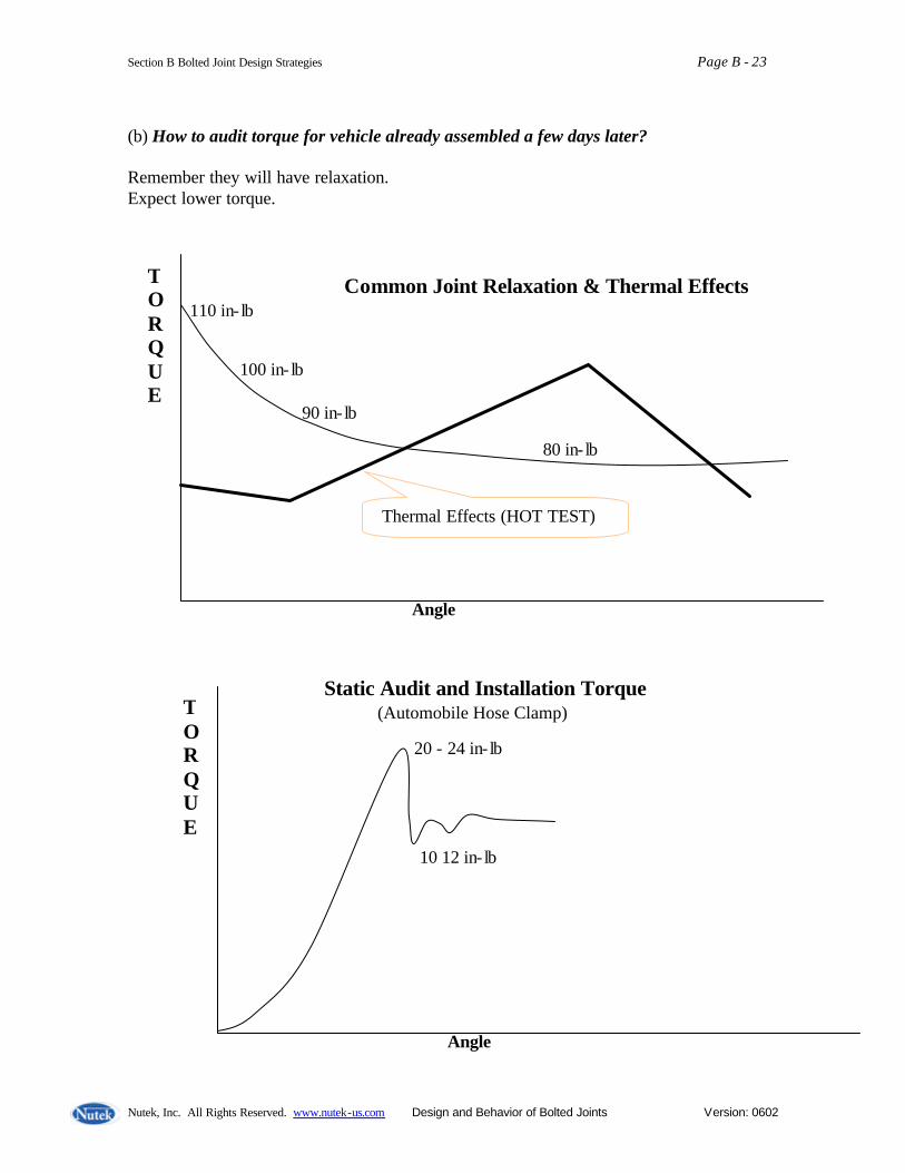
Section B Bolted Joint Design Strategies Page B - 23
Nutek, Inc. All Rights Reserved. www.nutek-us.com Design and Behavior of Bolted Joints Version: 0602
(b) How to audit torque for vehicle already assembled a few days later? Remember they will have relaxation. Expect lower torque.
TORQUE
Angle
20 - 24 in- lb
10 12 in- lb
Static Audit and Installation Torque (Automobile Hose Clamp)
TORQUE
Angle
110 in- lb
100 in- lb
90 in- lb
80 in- lb
Common Joint Relaxation & Thermal Effects
Thermal Effects (HOT TEST)

Section B Bolted Joint Design Strategies Page B - 24
Nutek, Inc. All Rights Reserved. www.nutek-us.com Design and Behavior of Bolted Joints Version: 0602
(c) Typical Breakaway (Static Audit) and Installation Torque Data Data for a certain engine head bolt samples are as follows. In many applications audit torque could be quite different from the dynamic installation torque.
Static Audit Torque Sample size = 10 97 108 110 98 107 112 89 92 98 104
Average = 101.5 Std. Dev. = 7.835
Dynamic installation Torque Sample size = 10 92 86 87 88 90 89 93 86 84 87
Average = 88.2 Std. Dev. = 2.82
1 2 3 4 5 6 7 8 9 10 Samples
TORQUE
100 in-lb.
80 in-lb
Avg.=101.5 S.Dev= 7.8 Avg.= 88.2 S.Dev= 2.82

Section B Bolted Joint Design Strategies Page B - 25
Nutek, Inc. All Rights Reserved. www.nutek-us.com Design and Behavior of Bolted Joints Version: 0602
(d) Stick Slip Friction Observed application: Connecting rod.
Problems caused by Static-Slip • Unreliable static audit torque • Erratic torque scatter with certified power tool • Low clamp force • Less reliable data for tension control Fixes to prevent Stick-Slip • S (plain) finish with SAE 50 oil • Electroplated Cadmium • Hardened Washer
TORQUE
TIME (seconds)
STICT-SLIP FRICTION is a condition where the sliding parts (nut or bolt) stick and slip in erratic non-predictable manner. Under this condition, the torque rate instantaneously changes from low to high and from high to low. (may occur and go away randomly) Occurrences • Occurs when lubrication medium breaks down. • More prevalent with S2 finish

Section B Bolted Joint Design Strategies Page B - 26
Nutek, Inc. All Rights Reserved. www.nutek-us.com Design and Behavior of Bolted Joints Version: 0602
Estimation of Joint Stiffness Using Torque Turn Data Although, the torque-turn plot may not be linear at all angles, its slope at any point can be established by taking ratio of the experimentally determined incremental values of toque and turn. ?T = Apply and measure value of torque applied to the bolt (in.lb.) ?? = Measure angle of rotation (in degrees) Compute ratio of the two as
TORQUE
ANGLE
? T
? ?
?? ? T Notations
?F = Incremental preload in bolt ?T = Incremental torque of bolt ?? = Incremental turn of bolt (deg.) ?L = Incremental bolt stretch KB = Bolt stiffness KJ = Joint stiffness KEqv = Equivalent Bolt-Joint stiffness K = Nut factor D = Bolt diameter P = Bolt thread pitch E = Young’s modulus of elasticity AS = Stress area of bolt Leff = Effective length of bolt = Torque to turn ratio = Spring stiffness
?? ? T
?X ?F
FP
T , ?
? ?
? T

Section B Bolted Joint Design Strategies Page B - 27
Nutek, Inc. All Rights Reserved. www.nutek-us.com Design and Behavior of Bolted Joints Version: 0602
F
X
? FPT
? X
For a loaded spring, F = KX, or K = F/X Similarly for spring of equivalent olt-joint that undergoes an incremental extension 9 ?L) under incremental load (?F) is ?F = KEqv x ?L or Since Thus
KB
KJ KJ
Equivalent stiffness of joint assembly. 1
+KB 1
KJ 1 KEq =
1
+
K B 1
K J 1 K Eqv =
1
+
K B 1
K J 1
?F = x ?L
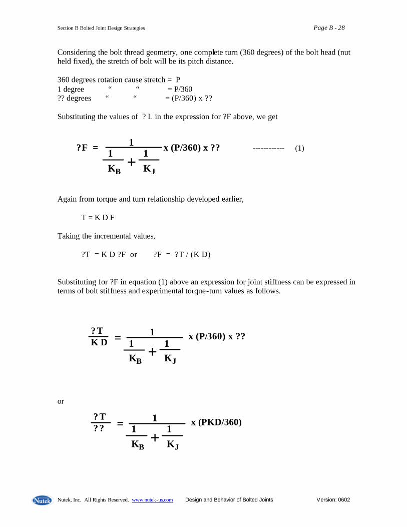
Section B Bolted Joint Design Strategies Page B - 28
Nutek, Inc. All Rights Reserved. www.nutek-us.com Design and Behavior of Bolted Joints Version: 0602
Considering the bolt thread geometry, one complete turn (360 degrees) of the bolt head (nut held fixed), the stretch of bolt will be its pitch distance. 360 degrees rotation cause stretch = P 1 degree “ “ = P/360 ?? degrees “ “ = (P/360) x ?? Substituting the values of ? L in the expression for ?F above, we get Again from torque and turn relationship developed earlier, T = K D F Taking the incremental values,
?T = K D ?F or ?F = ?T / (K D) Substituting for ?F in equation (1) above an expression for joint stiffness can be expressed in terms of bolt stiffness and experimental torque-turn values as follows. or
1
+
K B 1
K J 1
?F = x (P/360) x ?? ------------ (1)
1
+
K B 1
K J 1
x (P/360) x ?? ? T K D =
1
+
K B 1
K J 1
x (PKD/360) ? T ? ? =
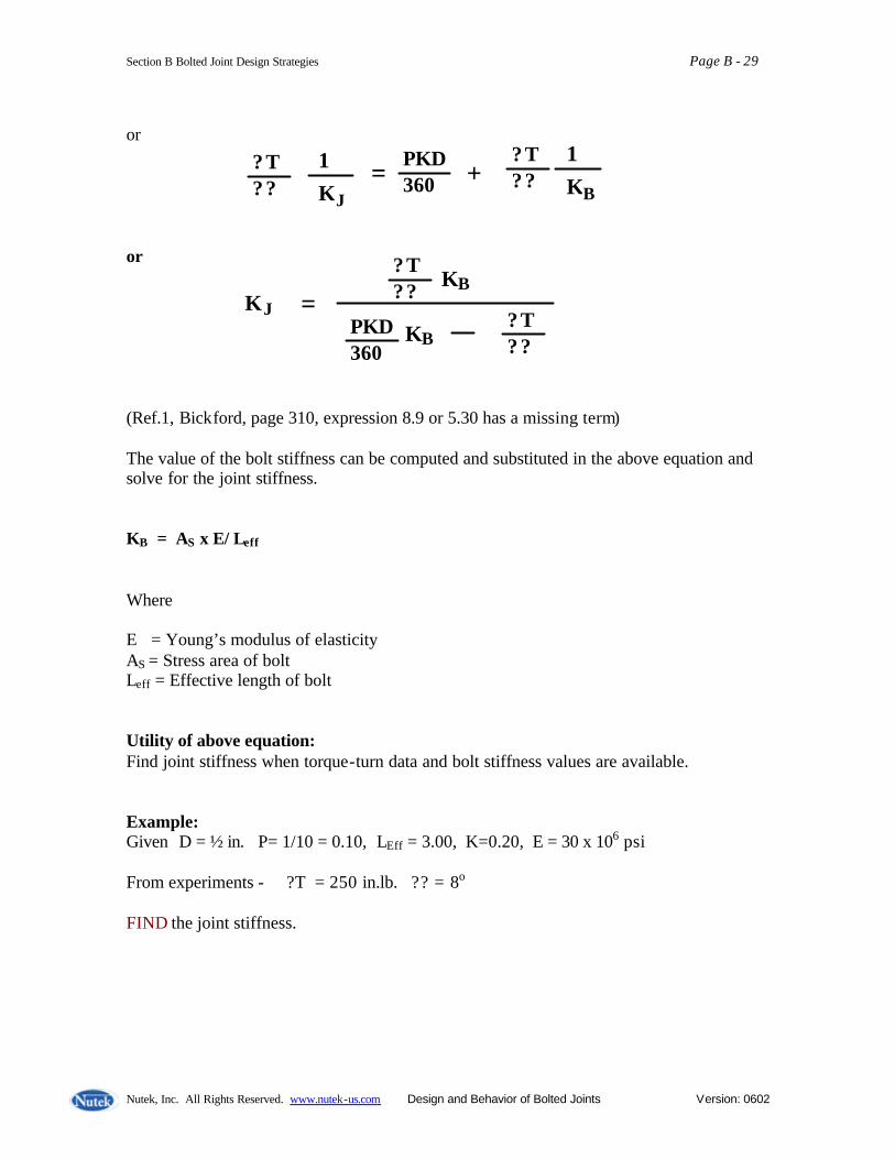
Section B Bolted Joint Design Strategies Page B - 29
Nutek, Inc. All Rights Reserved. www.nutek-us.com Design and Behavior of Bolted Joints Version: 0602
or or (Ref.1, Bickford, page 310, expression 8.9 or 5.30 has a missing term) The value of the bolt stiffness can be computed and substituted in the above equation and solve for the joint stiffness. KB = AS x E/ Leff Where E = Young’s modulus of elasticity AS = Stress area of bolt Leff = Effective length of bolt Utility of above equation: Find joint stiffness when torque-turn data and bolt stiffness values are available. Example: Given D = ½ in. P= 1/10 = 0.10, LEff = 3.00, K=0.20, E = 30 x 106 psi From experiments - ?T = 250 in.lb. ?? = 8o FIND the joint stiffness.
? T ? ?
+ K B 1
K J 1 ? T
? ? = PKD 360
? T ? ?
K J ? T ? ?
= PKD 360
K B
K B

Section B Bolted Joint Design Strategies Page B - 30
Nutek, Inc. All Rights Reserved. www.nutek-us.com Design and Behavior of Bolted Joints Version: 0602
Solution: Stress area of bolt, AS = 0.785 (0.50 - 0.974/10)2 = 0.127 Sq. in. KB = 0.127 x 30 x 106 /3 (effective) = 1.27 x 10⁶ lbs/in. PKD/360 = 0.10 x 0.20 x 0.50/360 = 27.8 x 10⁻⁶ ?T/?? = 250/8 = 31.25 in.lb/degree KJ = (31.25 x 1.27 x 106 ) / (27.8 x 10⁻⁶ 1.27 x 10⁶ - 31.25) = 39.69 x 10⁶ / 4.056 = 9.785 x 10⁶ lbs/in Exercise: The effective length of an UN ¾ - 12 bolt is 2.75 in. Assume that the nut factor and Young’s modulus are K=0.16 and E = 30 x 106 psi. Experimental data for the joint torque and turn is as shown. Determine the joint stiffness. (Ans. 4.97 x 10⁶ lbs/in) Solution: AS = 0.785 (0.75 - 0.974/12)2 = 0.351 Sq. in. KB = 0.351 x 30 x 106 /2.75 = 3.83 x 10⁶ lbs/in. PKD/360 = (1/12) x 0.12 x 0.75/360 = 20.8 x 10⁻⁶ ?T/?? = 225/5 = 45 in.lb/degree KJ = (45x 3.83 x 106 ) / (20.8 x 10⁻⁶ 3.83 x 10⁶ - 45) = 172.35 x 10⁶ / 34.66 = 4.97 x 10⁶ lbs/in
T
è ? in Degrees
225 lb.in.
5o
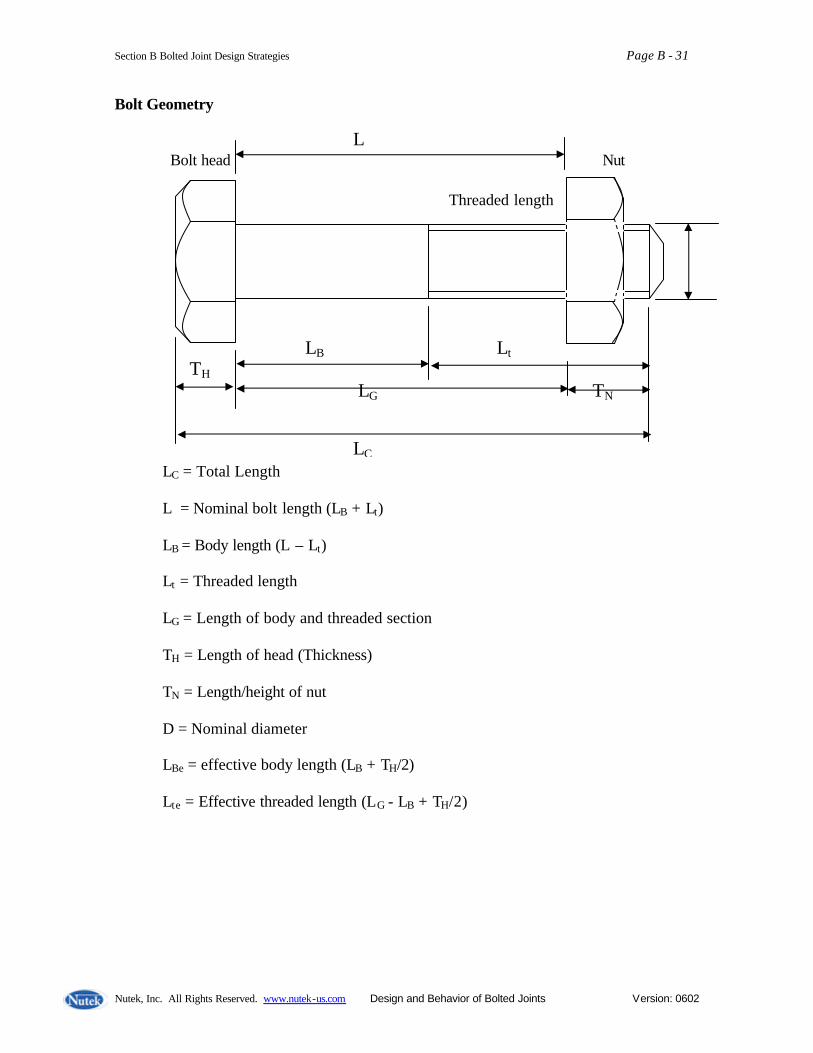
Section B Bolted Joint Design Strategies Page B - 31
Nutek, Inc. All Rights Reserved. www.nutek-us.com Design and Behavior of Bolted Joints Version: 0602
Bolt Geometry
LC = Total Length L = Nominal bolt length (LB + Lt) LB = Body length (L – Lt) Lt = Threaded length LG = Length of body and threaded section TH = Length of head (Thickness) TN = Length/height of nut D = Nominal diameter LBe = effective body length (LB + TH/2) Lte = Effective threaded length (LG - LB + TH/2)
L Bolt head Nut Threaded length
Thread D
LB Lt TH LG TN LC

Section B Bolted Joint Design Strategies Page B - 32
Nutek, Inc. All Rights Reserved. www.nutek-us.com Design and Behavior of Bolted Joints Version: 0602
Bolt Identification
Inch Series
Male, B-Female Thread
Class of fit NF = National Fine 1 – Very loose 2-free fit* NC = National Course3 – Close fit 4 – Snug fit 5 – Interference fit *Most Ford applications # of Threads per inch 1/13 = pitch
Nominal bolt diameter Metric Series
Position of thread (efgh) Lowercase for external thread Upper case for internal thread 1, 2, …9 amount of tolerance 1 – smallest, 9 – larger
Pitch in m.m.
Outside diameter in mm Metric
½ - 13 NC 3 A
M 10 x 1.5p – 6H
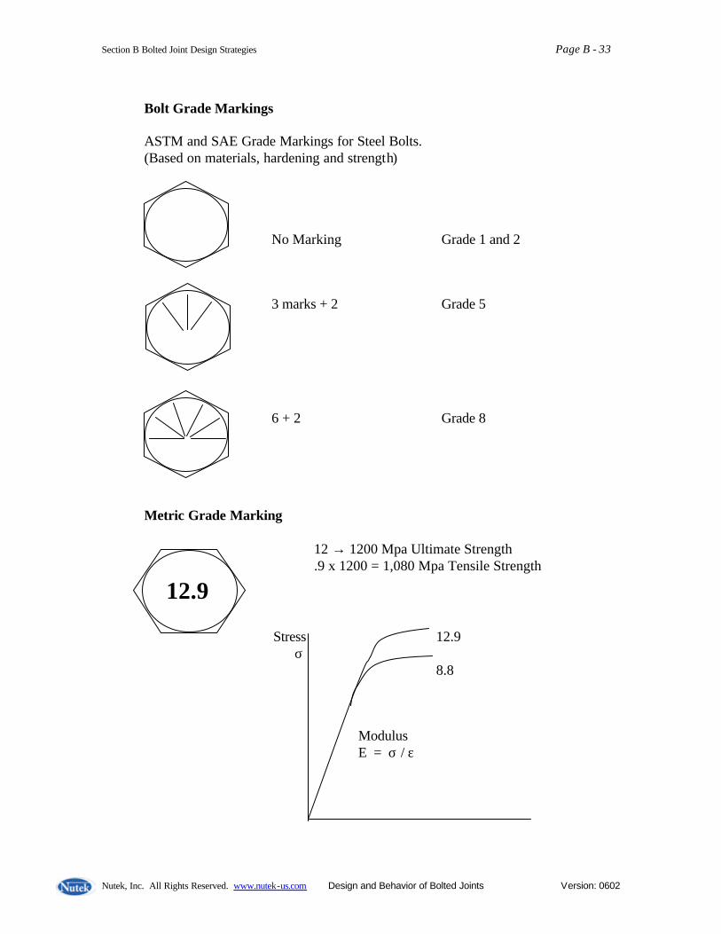
Section B Bolted Joint Design Strategies Page B - 33
Nutek, Inc. All Rights Reserved. www.nutek-us.com Design and Behavior of Bolted Joints Version: 0602
Bolt Grade Markings ASTM and SAE Grade Markings for Steel Bolts. (Based on materials, hardening and strength) No Marking Grade 1 and 2 3 marks + 2 Grade 5 6 + 2 Grade 8 Metric Grade Marking 12 → 1200 Mpa Ultimate Strength .9 x 1200 = 1,080 Mpa Tensile Strength
12.9 Stress 12.9 σ 8.8 Modulus E = σ / ε

Section B Bolted Joint Design Strategies Page B - 34
Nutek, Inc. All Rights Reserved. www.nutek-us.com Design and Behavior of Bolted Joints Version: 0602
Torque, Angle, and Tension Measuring Devices Torque Measuring Tools
1. Reaction type • Electronic • Mechanical (Dial or Clicker)
Typically used for torque audit in the plant. Individual pressure regulator for each tool desirable.
2. Rotary type
• Slip Ring • Rotary Transformers
Strain gauges calibrated to indicate torque within +/ - ½ %
Inclined Plane
ROTARY TRANSFORMER More delicate instrument. Used primarily for certification of power tool in the laboratories.

Section B Bolted Joint Design Strategies Page B - 35
Nutek, Inc. All Rights Reserved. www.nutek-us.com Design and Behavior of Bolted Joints Version: 0602
Angle Measuring Transducers
Tension Measuring Equipment Load Washer (for clamp load in bolt) Load Cell
• Are not influenced by friction • Need to machine the part to accommodate the Load Cell.
Rotary transducer with built- in Light Emitting Diode (LED).
Accuracy +/- 10% Strain gauges Hardened steel washers Used to control friction.

Section B Bolted Joint Design Strategies Page B - 36
Nutek, Inc. All Rights Reserved. www.nutek-us.com Design and Behavior of Bolted Joints Version: 0602
Bolt Converted to Load Cell (STRAINCERT BOLT) Accuracy within +/- 1% It changes the stress characteristics of the bolt. The drilled hole is small enough such that Crossection > X-section at core dia. Used for measuring loads of Engine Cylinder bolts. Length Change Method (Physical Measurement) Lf = final length (loaded) Lo = free length (unloaded) ∆L = Lf - Lo Load P = ∆L (EA/L) Drilled Hole Length Measure length of drilled hole by a thin rod. Expensive. Not much used in automotive.
Straincert Bolt ½ GL Grip Length GL Bolt with drilled hole and strain Gauge.
Length
Unloaded Loaded
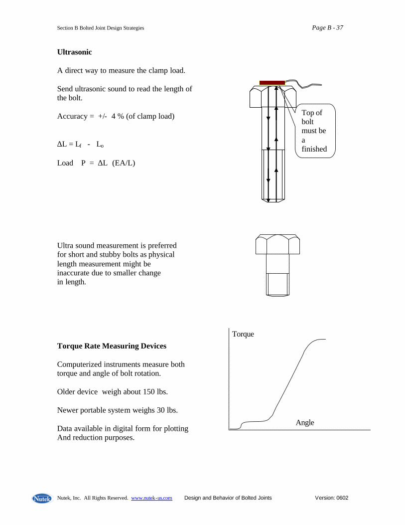
Section B Bolted Joint Design Strategies Page B - 37
Nutek, Inc. All Rights Reserved. www.nutek-us.com Design and Behavior of Bolted Joints Version: 0602
Ultrasonic A direct way to measure the clamp load. Send ultrasonic sound to read the length of the bolt. Accuracy = +/- 4 % (of clamp load) ∆L = Lf - Lo Load P = ∆L (EA/L) Ultra sound measurement is preferred for short and stubby bolts as physical length measurement might be inaccurate due to smaller change in length. Torque Rate Measuring Devices Computerized instruments measure both torque and angle of bolt rotation. Older device weigh about 150 lbs. Newer portable system weighs 30 lbs. Data available in digital form for plotting And reduction purposes.
Top of bolt must be a finished
Torque
Angle
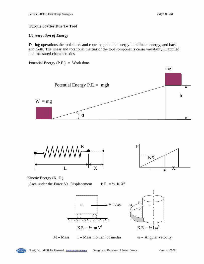
Section B Bolted Joint Design Strategies Page B - 38
Nutek, Inc. All Rights Reserved. www.nutek-us.com Design and Behavior of Bolted Joints Version: 0602
Torque Scatter Due To Tool Conservation of Energy During operations the tool stores and converts potential energy into kinetic energy, and back and forth. The linear and rotational inertias of the tool components cause variability in applied and measured characteristics. Potential Energy (P.E.) = Work done
Kinetic Energy (K. E.)
θ
mg Potential Energy P.E. = mgh h W = mg
K F KX L X X Area under the Force Vs. Displacement P.E. = ½ K X2
m V in/sec ω I K.E. = ½ m V2 K.E. = ½ I ω2 M = Mass I = Mass moment of inertia ω = Angular velocity
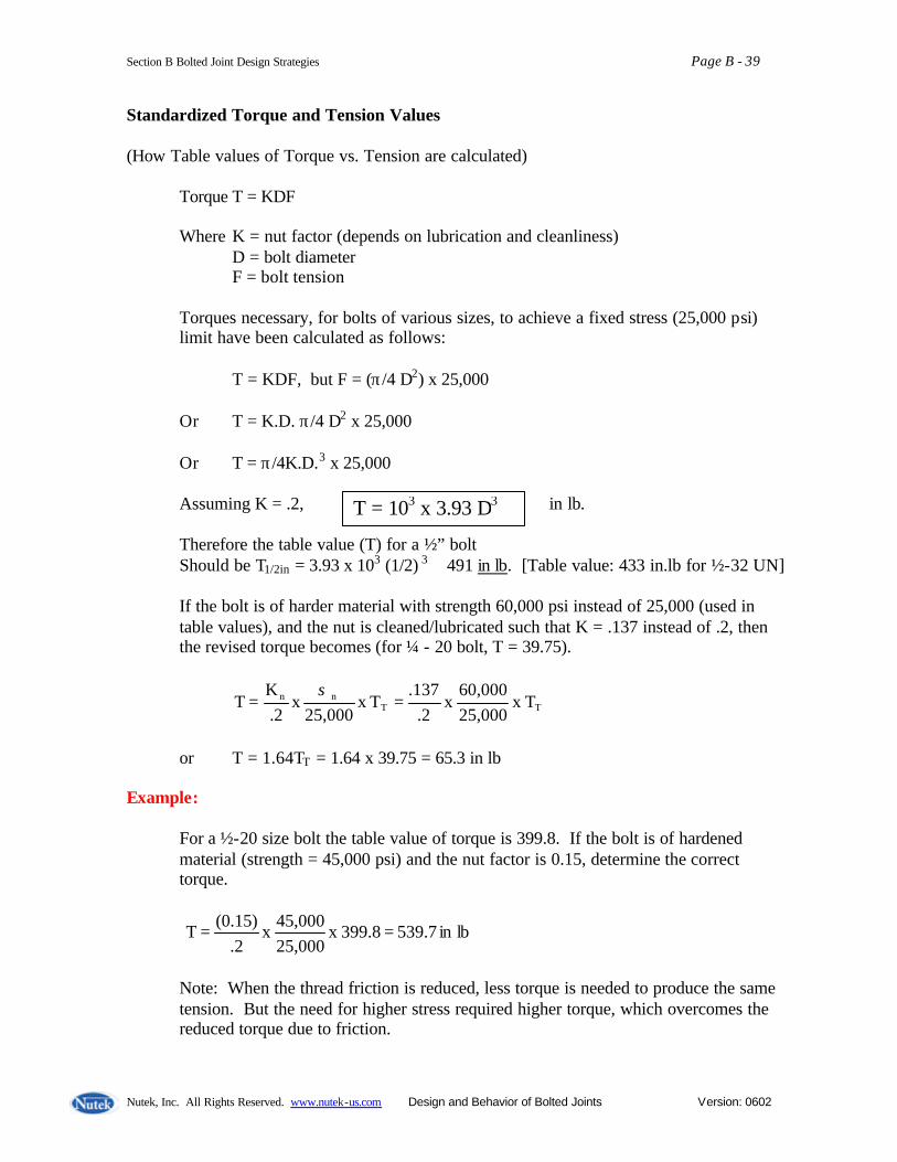
Section B Bolted Joint Design Strategies Page B - 39
Nutek, Inc. All Rights Reserved. www.nutek-us.com Design and Behavior of Bolted Joints Version: 0602
Standardized Torque and Tension Values (How Table values of Torque vs. Tension are calculated)
Torque T = KDF Where K = nut factor (depends on lubrication and cleanliness) D = bolt diameter F = bolt tension
Torques necessary, for bolts of various sizes, to achieve a fixed stress (25,000 psi) limit have been calculated as follows: T = KDF, but F = (π/4 D2) x 25,000 Or T = K.D. π/4 D2 x 25,000 Or T = π/4K.D.3 x 25,000 Assuming K = .2, in lb. Therefore the table value (T) for a ½” bolt Should be T1/2in = 3.93 x 10³ (1/2) 3 ≅ 491 in lb. [Table value: 433 in.lb for ½-32 UN] If the bolt is of harder material with strength 60,000 psi instead of 25,000 (used in table values), and the nut is cleaned/lubricated such that K = .137 instead of .2, then the revised torque becomes (for ¼ - 20 bolt, T = 39.75).
TTnn T x
25,00060,000
x 2.
137.Tx
25,000x
2.K
T ==σ
or T = 1.64TT = 1.64 x 39.75 = 65.3 in lb
Example:
For a ½-20 size bolt the table value of torque is 399.8. If the bolt is of hardened material (strength = 45,000 psi) and the nut factor is 0.15, determine the correct torque.
lbin 539.7 399.8 x 25,00045,000
x .2
(0.15) T ==
Note: When the thread friction is reduced, less torque is needed to produce the same tension. But the need for higher stress required higher torque, which overcomes the reduced torque due to friction.
T = 103 x 3.93 D3
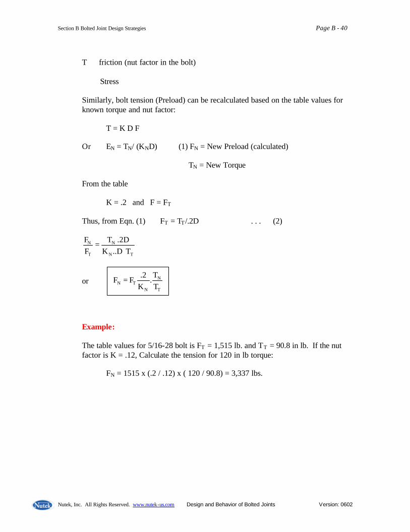
Section B Bolted Joint Design Strategies Page B - 40
Nutek, Inc. All Rights Reserved. www.nutek-us.com Design and Behavior of Bolted Joints Version: 0602
T ∝ friction (nut factor in the bolt) ∝ Stress
Similarly, bolt tension (Preload) can be recalculated based on the table values for known torque and nut factor: T = K D F Or EN = TN/ (KND) (1) FN = New Preload (calculated) TN = New Torque From the table K = .2 and F = FT Thus, from Eqn. (1) FT = TT/.2D . . . (2)
TN
N
T
N
T D..K.2D T
FF
=
or
Example:
The table values for 5/16-28 bolt is FT = 1,515 lb. and T T = 90.8 in lb. If the nut factor is K = .12, Calculate the tension for 120 in lb torque: FN = 1515 x (.2 / .12) x ( 120 / 90.8) = 3,337 lbs.
T
N
NTN T
T.
K2.
F F =

Section B Bolted Joint Design Strategies Page B - 41
Nutek, Inc. All Rights Reserved. www.nutek-us.com Design and Behavior of Bolted Joints Version: 0602
Bolt Strengths (Standard Table values of Torque vs. Tension)
English 25,000 psi = 172.4 Mpa Size Series Tensile Strength
area (in2) Preload For 25 ksi (lbs) x 103
(in- lb) Torque to achieve 25 KSI stress
0-80 UNF .00180 .045 .54 1-64 .
UNC .00263 .065.8 .96
12-32 UNEF .0270 .675 29.2 ¼-20 UNC .0318 .795 39.75 ¼-28 .:
UNF .0364 .910 45.5
½ - 13 UNC .1419 3.548 354.8 ½ - 32 UN .173 4.325 433 ½ - 16 :
UNF .151 3.775 378
1 – 8 UNC .606 15.150 3,030 1 – 12 :
UNF .663 15.58 3,316
Metric Series Size Area
(mm2) Preload 172.4 Mpa (KN)
Torque for 172.4 Mpa
M1.6 x .35 1.27 0.219 .070 M2 x .4 :
2.07 0.357 .1428
M6 x 1 :
20.1 3.465 4.158
M12 x 1.75 :
84.3 14.533 34.9
M24 x 3 353. 60.96 292.6
Section B Bolted Joint Design Strategies Page B - 42
Nutek, Inc. All Rights Reserved. www.nutek-us.com Design and Behavior of Bolted Joints Version: 0602
Overview of Bolted Joint Design Designing a bolted joint design is an iterative process, in that the designer generally relies on trial and error, past experience and personal judgment to make some design decisions. Obviously, experience and knowledge of the designer play an important role. With increases experience, the designer is able to make better decisions about the effect of certain design parameters. However, regardless of the size, application or operating parameters of a joint, there are some steps which are commonly undertaken. These steps include: Following are many of the critical factors that apply to all bolted joint designs regardless of the size, application or operating parameters. 1. Define purpose Determine and define the following:
- desired function of joint - environmental conditions - cost targets - size and operating parameters - desired life - critical nature - potential failure modes - any other factors involved influencing joint function.
2. Design joint. Determine the layout of the joint, including joint members, size, shape and material(s). 3. Estimate service loads Estimating service loads is a difficult, but very important step, especially in critical joints. The static and dynamic loads to be considered include weight, pressure, shock, inertial affects, thermal affects, etc. Load intensifiers, such as prying and eccentricity, should also be considered. 4. Select bolts After the joint geometry and service loads are established, the bolt size, number and strength can be determined. As part of the bolt selection, you should identify
- material - diameter - thread pitch - length - tensile strength - head style - drive style - thread style - hardness and - Anticorrosion coating/plating.

Section B Bolted Joint Design Strategies Page B - 43
Nutek, Inc. All Rights Reserved. www.nutek-us.com Design and Behavior of Bolted Joints Version: 0602
5. Determine required minimum and maximum preload & clamp load. Preload at assembly should be selected such that the desired clamp necessary for proper function of the joint throughout the life can be achieved. Preload > clamp load after relaxation Minimum clamping force > force necessary to overcome vibration loosening, joint separation, slippage, fatigue, leakage and other similar type failures. Maximum clamp force < force that can cause bolt yielding, joint crushing, stress cracking, fatigue failure, tensile failure or other similar failures in service. 6. Determine tightening methods and assembly torque There are different fastener assembly methods and tightening strategies available. A proper method and strategy must be selected based on accuracy of achieving preload (P), nut factor (K), and required tightening torque. Commonly desired preload accuracy is:
Torque: ±35% Torque-Angle: ±15% Torque-to-Yield: ± 7% T = KDP Suppose that we wish to use a UNC 3/8 – 16 bolt with K factor of 0.20. The yield strength of the fastener is 5,000 lbs. minimum. If we use 80% as the design preload, that is 5,000 x 0.80 = 4,000 lbs. The assembly torque then becomes: T = .20 x (3/8) x 4,000, or T = 300 lb.in 7. Release joint design. Review and modify joint material, bolt preload range, bolt selection, tightening methods, etc. if necessary. 8. Experimental Joint Data Joint design is not an exact science. Testing joint designs to ensure that the application achieves the desired level of reliability is very important. Experimental verification of the long term performance is essential for critical joints.

Section B Bolted Joint Design Strategies Page B - 44
Nutek, Inc. All Rights Reserved. www.nutek-us.com Design and Behavior of Bolted Joints Version: 0602
Bolted Joint Design Strategy Goal → Reliable Joints [Comes from Sound design + quality part + Proper assembly] Considerations for design vary depending on the design. But following checklist generally apply to all. Checklist of reliable designs (bolted joints):
Mechanism – Bolted joint is a clamp. Unreliable joint is similar to an “inadequate clamp”. Reliability – Strong enough to give structural integrity, resist separation, prevent slip, overcome misalignment.
- enough number of bolts - appropriate material strength - acceptable resistance to fatigue - acceptable relaxation and creep - acceptable temperature relaxation
Bolt & Joint geometry – minimize stress concentration (bolt-head-to-shank fillets, thread run out, etc.) In-Service clamping force – preload modified by service loads and thermal effects. Must be enough to minimize self- loosening.
Design Steps 1. Description of joints: Establish the purpose of the design. Identify the operating condition of the equipment in which the joint is located. Speed, vibration, impact, temperature, desired life, etc. 2. Preliminary design: Rough layout of sizes and shapes of various parts. 3. Estimate of Loading: Determine (estimate) service loads by considering –
weight, pressure, inertia, thermal effect, etc. 4. Select Bolt – Nominal dia.
- Static strength - Upper tension limit - Stripping strength of threaded area.
(a must if threaded engagement is short)
Section B Bolted Joint Design Strategies Page B - 45
Nutek, Inc. All Rights Reserved. www.nutek-us.com Design and Behavior of Bolted Joints Version: 0602
5. Required Minimum Clamping Force
Clamping force > external load (must always) The amount by which clamping in-service force should exceed external load depends on:
- accuracy of bolt tightening - correctness of the estimate of externa l load - relaxation over time - unknown overloading
Also: Joint Slip – high tension needed to resist shear load.
Self Loosening – transverse load causes slip between joint members and threaded surfaces. Pressure loads – Example: cylinder, boiler. Joint Separation – Under gravity held part clamp load is needed only
for alignment and can be very low. Fatigue – in this case minimum clamp load calculation is quite
complicated . 6. Upper Limit of Clamping Force
Loosening (slip leak) < Clamping force (Fc) < upper limit Generally, we want the maximum clamping force the parts can stand.
Upper limit < Bolt yield strength (current trend in automotive application is to just go past yield) < Thread stripping strength (worse case upper limit)
< Allowable bolt stress and Assembly Stress limits by codes, standard, bias, company practices. < Torsional Stress Factor < Shear Stress Allowances Other limits may be imposed by:
Flange rotation, Gasket crush, Stress cracking (for service load over 50% yield), combined load.
Section B Bolted Joint Design Strategies Page B - 46
Nutek, Inc. All Rights Reserved. www.nutek-us.com Design and Behavior of Bolted Joints Version: 0602
(Specifying TORQUE based on CLAMPING road required) Joint Assembly and Behavior [Assembly viewpoint, determining what torque to specify) Now that we understand that CLAMP LOAD is what we are after, but the only practical way to obtain it is to apply the TORQUE, which is full of uncertainty. So, how do we determine what torque should we specify after the joint is designed (both and joint members)? Theoretical approach: 1. Goal – Secure Correct Clamping Force 2. What clamping force is “right” for the joint?
(a) acceptable range at application (b) expected range of tension obtainable after assembly (c) what happens after assembly
- time, environment, application, temperature, etc. 3. Assembly Preload – Generally not known
(a) Past experience – considered best guide (b) Ask the designer – second best (c) Unimportant joint and no prior knowledge
- use the table value
(d) Concerned effort – calculate bolt torque analytically T = K.D. (Sy.A)P P = % of yield stress used for loading K = constant, D = bolt dia., Sy = yield strength
4. Anticipated Preload in service. . . etc.

Section B Bolted Joint Design Strategies Page B - 47
Nutek, Inc. All Rights Reserved. www.nutek-us.com Design and Behavior of Bolted Joints Version: 0602
Typical Target Preload (As % of Yield Strength)
Preload as % of Yield Load Common Situations 25% Foundations, anchor bolts non-
(if σy = 30,000 psi, then gasketed joints Bolt Stress = 7,500 psi)
40% Gasketed joints in routine service 50% - 60% Average non-gasketed joints “normal”
safety concerns. Max. for gasketed joint. 70 – 75% Upper limit for non-gasketed joints with
previous “low preload” problems. 85 – 95% Joints with previous “low preload”
problem occurred consistently. Where it is unwise to reach load.
100% Structural steel bolts tightened by turn-
of-nut procedures. Joint facing fatigue, self- loosening, where service load can be predicted with accuracy.
Experimental approach: Case 1: Threaded Bolt 1. Tighten and measure yield torque for a set (10 or more)
samples. 2. Calculate average(a) and standard deviation(s) of Yield torque. 3. Determine relaxation factor (torque multiplier to compensate for loss of torque). 4. Specify TORQUE at six standard deviation below the average yield torque (= a – 6s)
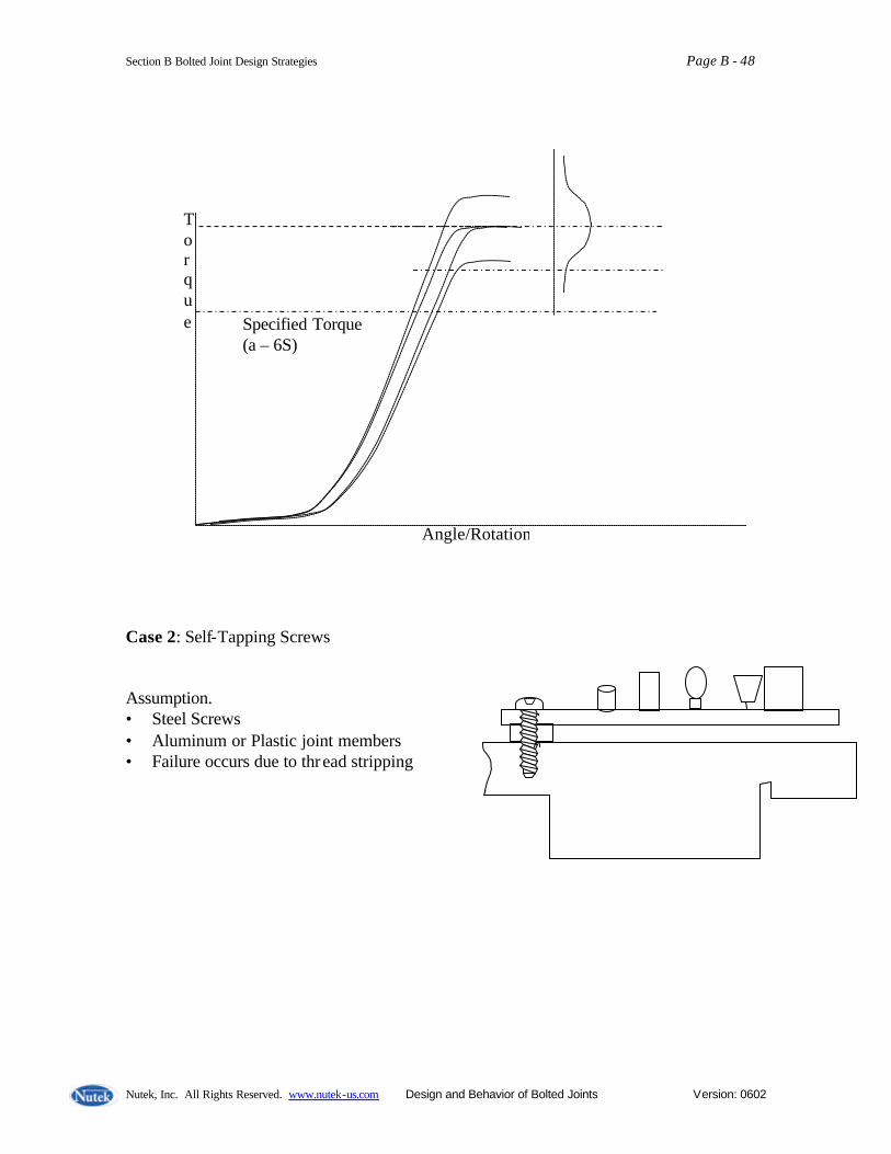
Section B Bolted Joint Design Strategies Page B - 48
Nutek, Inc. All Rights Reserved. www.nutek-us.com Design and Behavior of Bolted Joints Version: 0602
Case 2: Self-Tapping Screws Assumption. • Steel Screws • Aluminum or Plastic joint members • Failure occurs due to thread stripping
Angle/Rotation
Torque Specified Torque
(a – 6S)
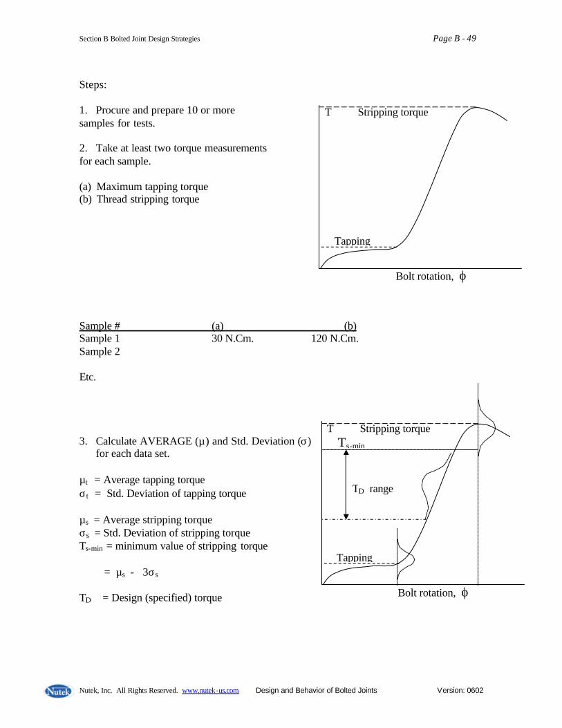
Section B Bolted Joint Design Strategies Page B - 49
Nutek, Inc. All Rights Reserved. www.nutek-us.com Design and Behavior of Bolted Joints Version: 0602
Steps: 1. Procure and prepare 10 or more samples for tests. 2. Take at least two torque measurements for each sample. (a) Maximum tapping torque (b) Thread stripping torque Sample # (a) (b) Sample 1 30 N.Cm. 120 N.Cm. Sample 2 Etc. 3. Calculate AVERAGE (µ) and Std. Deviation (σ)
for each data set. µt = Average tapping torque σt = Std. Deviation of tapping torque µs = Average stripping torque σs = Std. Deviation of stripping torque Ts-min = minimum value of stripping torque = µs - 3σs TD = Design (specified) torque
T Stripping torque
Tapping
Bolt rotation, ϕ
T Stripping torque
Tapping
Bolt rotation, ϕ
Ts-min
TD range

Section B Bolted Joint Design Strategies Page B - 50
Nutek, Inc. All Rights Reserved. www.nutek-us.com Design and Behavior of Bolted Joints Version: 0602
4. Specify torque as 80% of minimum stripping torque. TD = 0.80 x Ts-min Alternate approach. Assuming that the specified torque will have Standard Deviation same as the stripping torque (σs), the specified torque should be 3σs below the Ts-min . That is TD = Ts-min - 3σs The above value represents the upper limit of the design torque. The lower limit should be above the upper range of the tapping torque. Case 3: Bolted Joint (nut or threaded part. Conventional approach) 1. Procure and prepare 10 or more samples for tests (destructive) 2. Find maximum Prevailing Torque and Toque to Yield data for each sample. Prevailing torque should be found by intersection of two straight line idealized to represent the initial torque build up portion and the elastic range of the torque Vs. angle graph as shown below. The Toque to yield is found by the tangent to the top part of the torque vs. angle plot.
T Torque to Yield
Prevailing Torque
Bolt rotation, ϕ

Section B Bolted Joint Design Strategies Page B - 51
Nutek, Inc. All Rights Reserved. www.nutek-us.com Design and Behavior of Bolted Joints Version: 0602
3. Find the Average and Standard Deviation of the sample data (10 or more) 4. Specify torque at 80% of the minimum Torque to Yield. 5. Find relaxation factor by conducting additional tests. Measure Static Audit Torque for
each of the above test samples at 2 min. 10 min, 1 hr. ½, 1 day, 5 days, and 1 month time interval. Plot data, Audit Torque vs. Time. Find the torque at stable (horizontal) portion of the curve. Find Relaxation factor, CR as the ratio of the Audit toque at the beginning to that at the stable condition (do not use if no stable value is found). Modify the design torque by multiplying by the Relaxation factor.
Generalized Hooke’s Law Linear Strain ε = σ/E σ ∝ proportional limit or E = σ/ε and σ = Eε Shear Strain γXY = J XY/G or G = J XY/γXY or J XY = γXYG
Yield Stress Crystalline Materials (Engineering Metals) C
D Stress Fracture A Yield Strength B ε =.001 in/in ε =.002 in/in ε =.25 in/in Strain
Steel 1020 (hot rolled) σu = 67,00 psi, σy = 45,000, BHN = 137 1010 (hot rolled) σu = 51,00 psi, σy = 29,000, BHN = 101

Section B Bolted Joint Design Strategies Page B - 52
Nutek, Inc. All Rights Reserved. www.nutek-us.com Design and Behavior of Bolted Joints Version: 0602
Mechanical Properties of Steel
E = Young’s Modules, G = Torsional modules, µ = Poison’s ratio, ε t/Eaxial
∝ = Thermal Expansion
Properties of Plane Areas
Hot Rolled Steel (SAE 1020) E = 30 x 106 psi G = 12 x 106 psi µ = .27 (friction) σy(.2%) = 36,000 psi σu = 65,000 w = .283 lb/in3 ∝ = 6.5 x 10⁻⁶
High Carbon Steel (SAE 1090) E = 30 x 106 psi G = 12 x 106 psi µ = .27 σy(.2%) = 67,000 psi σu = 122,000 psi w = .283 lb/in3 ∝ = 6.5 x 10⁶/° F
Aluminum 1100.0 annealed E = 10 x 106 psi G = 3.8 x 10⁶ psi µ = .33 σy(.2%) = 3,500 psi σu = 11,000 psi w = .098 lb/in3 ∝ = 13.1 x 10⁶/° F
Area A = bh Ixc = bh3 / 12 h/2 xc Ixb = bh3 / 3 h b b
A = Π d2 / 4 Ixc = Π d4 / 64 xc c Jc = Π d4 / 32 d
Ixc = Π (do
4 - di4 )/ 64
Jc = Π (do
4 - di4 )/ 32
xc C
d
A = 2Π ravg. t t Ixc = Π r3
avg. t xc c ravg. Jc = 2Π r3
avg. t t << ravg

Section B Bolted Joint Design Strategies Page B - 53
Nutek, Inc. All Rights Reserved. www.nutek-us.com Design and Behavior of Bolted Joints Version: 0602
TORQUE CONTROL TOOLS The tools for application of torque are selected based on
• Productivity • Cost • Quality Reliability
Manual Torque Wrenches Speed – Slow Accuracy - + / - ( 2 to 20%) Incorporates Gauge, Dial, Click, and Electronic Torque Multipliers Accuracy – inadequate Hydraulic Wrenches Can produce high torque Usually slower Impact Wrenches Speed – very fast Accuracy - +/- 50% High maintenance
Lower operator reaction force Air Nutrunners Speed – slower (certified) faster (non-certified) Accuracy- 5 – 18% (certified), up to 40% (non-certified) Stall – dependent on operator influence Clutch – controlled by operator reaction (Air shut off) Electric Nutrunners Speed – usually slower Cost – uses lower energy Accuracy – more accurate with feedback control Impulse Torque Wrenches Speed – quicker
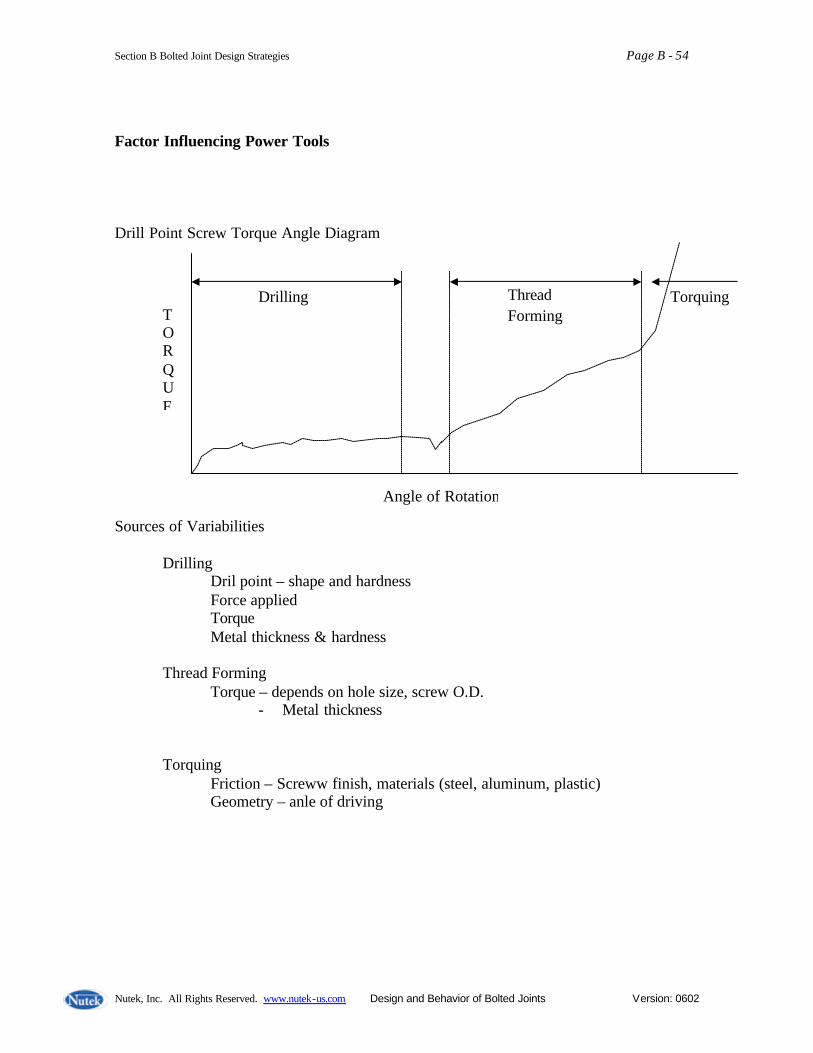
Section B Bolted Joint Design Strategies Page B - 54
Nutek, Inc. All Rights Reserved. www.nutek-us.com Design and Behavior of Bolted Joints Version: 0602
Factor Influencing Power Tools Drill Point Screw Torque Angle Diagram Sources of Variabilities Drilling Dril point – shape and hardness Force applied Torque Metal thickness & hardness Thread Forming Torque – depends on hole size, screw O.D.
- Metal thickness Torquing Friction – Screww finish, materials (steel, aluminum, plastic) Geometry – anle of driving
TORQUE
Angle of Rotation
Drilling Thread Forming
Torquing

Section B Bolted Joint Design Strategies Page B - 55
Nutek, Inc. All Rights Reserved. www.nutek-us.com Design and Behavior of Bolted Joints Version: 0602
Summary: Joint Assembly
Joint Assembly Considerations
• The main idea in a joint is to obtain proper clamping load. To secure proper clamping load, the joint must be well assembled.
• Clamping for is called the preload o Initial Preload – load while
tightening o Residual Preload – what’s left
after assembly o In-service Bolt tension – what’s
left after some time in service
Load and Torque Relation Initial Preload Torque
Reasons for Loss of Clamp Force Short Term relaxation due to:
• Contact embedment • High spots yielding between surfaces • Softer parts • Poor tread engagement • Large fillets • Oversized holes • Misaligned holes
- Can be avoided by longer bolt. - 2 – 11% without and 10 – 30% with gasket. - 100% with thick gasket and short bolts.
Elastic Interactions (Cross-talk between bolts) It is a phenomenon in which tightening one bolt affects the tension of another. It is an unavoidable situation present in some joints with multiple bolts.
• Is affected by joint gasket stiffness. • Can be compensated by bolting
pattern. • The net result is that it loosens bolt that
were previously tightened. • It is not a concern in many joints.
Torque and Turn Relation Torque Work Done Turn
Loss of Energy (about 90%)
Nut Friction Loss
Stored Energy
Thread Friction
Turn Angle
Torque
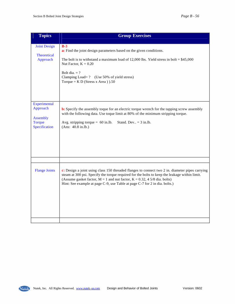
Section B Bolted Joint Design Strategies Page B - 56
Nutek, Inc. All Rights Reserved. www.nutek-us.com Design and Behavior of Bolted Joints Version: 0602
Topics Group Exercises
Joint Design
Theoretical Approach
B-3 a: Find the joint design parameters based on the given conditions. The bolt is to withstand a maximum load of 12,000 lbs. Yield stress in bolt = $45,000 Nut Factor, K = 0.20 Bolt dia. = ? Clamping Load= ? (Use 50% of yield stress) Torque = K D (Stress x Area ) ).50
Experimental Approach Assembly Torque Specification
b: Specify the assembly toque for an electric torque wrench for the tapping screw assembly with the following data. Use toque limit at 80% of the minimum stripping torque. Avg. stripping torque = 60 in.lb. Stand. Dev.. = 3 in.lb. (Ans: 40.8 in.lb.)
Flange Joints
c: Design a joint using class 150 threaded flanges to connect two 2 in. diameter pipes carrying steam at 300 psi. Specify the torque required for the bolts to keep the leakage within limit. (Assume gasket factor, M = 1 and nut factor, K = 0.32, 4 5/8 dia. bolts) Hint: See example at page C-9, use Table at page C-7 for 2 in dia. bolts.)
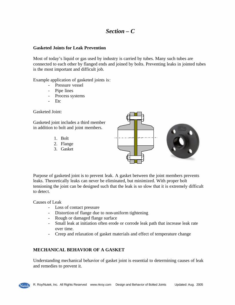
R. Roy/Nutek, Inc. All Rights Reserved www.rkroy.com Design and Behavior of Bolted Joints Updated: Aug. 2005
Section – C
Gasketed Joints for Leak Prevention
Most of today’s liquid or gas used by industry is carried by tubes. Many such tubes are connected to each other by flanged ends and joined by bolts. Preventing leaks in jointed tubes is the most important and difficult job. Example application of gasketed joints is:
- Pressure vessel - Pipe lines - Process systems - Etc
Gasketed Joint: Gasketed joint includes a third member in addition to bolt and joint members.
1. Bolt 2. Flange 3. Gasket
Purpose of gasketed joint is to prevent leak. A gasket between the joint members prevents leaks. Theoretically leaks can never be eliminated, but minimized. With proper bolt tensioning the joint can be designed such that the leak is so slow that it is extremely difficult to detect. Causes of Leak
- Loss of contact pressure - Distortion of flange due to non-uniform tightening - Rough or damaged flange surface - Small leak at initiation often erode or corrode leak path that increase leak rate
over time. - Creep and relaxation of gasket materials and effect of temperature change
MECHANICAL BEHAVIOR OF A GASKET Understanding mechanical behavior of gasket joint is essential to determining causes of leak and remedies to prevent it.

Section C Gasketed Joint Designs Page C - 2
Nutek, Inc. All Rights Reserved. www.nutek-us.com Design and Behavior of Bolted Joints Version: 0602
Gasket Stiffness – The load-deflection characteristic of a gasket is reported in terms of compressive stress and deflection. Assuming that the gasket in use is subjected to uniform stress, or load-deflection, the stiffness can be calculated from the measured values. Gasket parameters are usually determined by compressing a small gasket under hypothetically loaded platens. KJ = Joint stiffness, KF = Gasket stiffness and KG = Gasket stiffness, then (This represents two springs in series)
3. The spring constant of the gasket is much smaller than that of joint and/or bolt. It being of lower value dominates the elastic behavior of the joint assembly. (Two springs in series results in equivalent stiffness to be lower than the lower of the two.)
Examples: (i) KF = 4 and KG = 1 then KJ = 1 / [1/1 + 1/4 ] = 4/5 (lower than 1) (ii) KF = 12 and KG = 3 then KJ = 1 / [1/3 + 1/12 ] = 12/5 (lower than 31)
Key Observations
1. Gasket force-deflection curve is non- linear. This changes the stiffness value depending on the applied force (prediction becomes difficult)
2. Gasket inserts a third spring
in series with the joint.
KJ =
1 KG
+ 1
KF
1
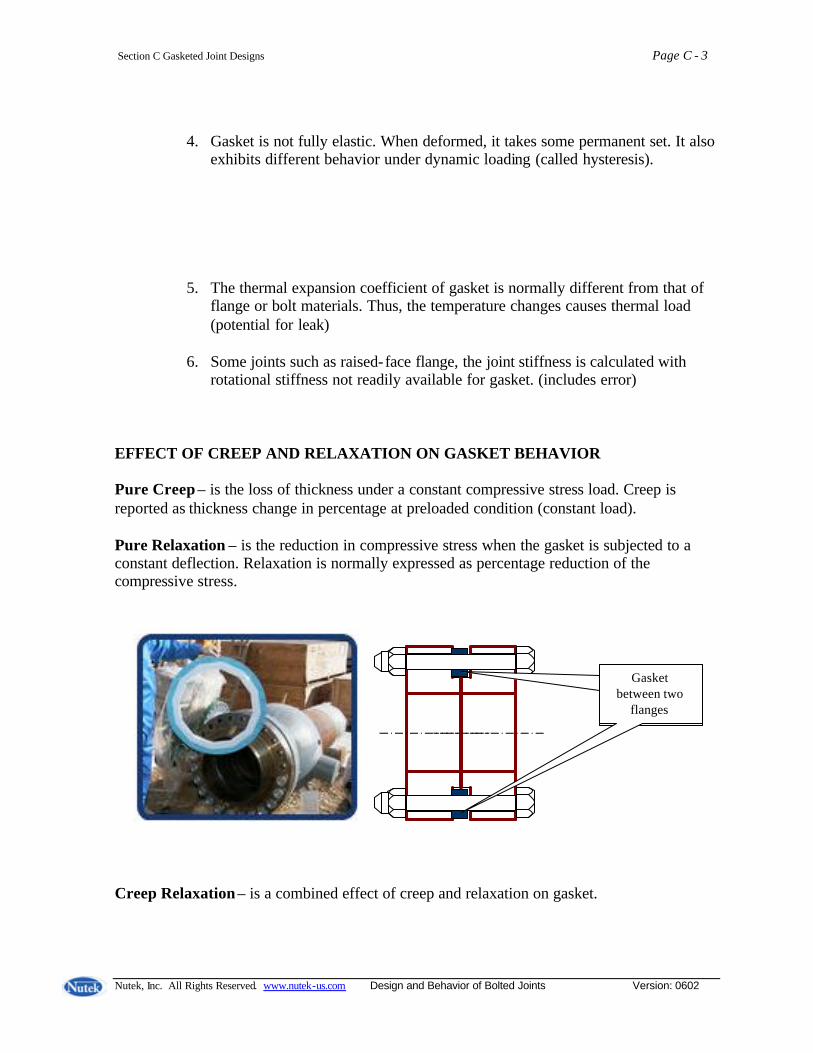
Section C Gasketed Joint Designs Page C - 3
Nutek, Inc. All Rights Reserved. www.nutek-us.com Design and Behavior of Bolted Joints Version: 0602
4. Gasket is not fully elastic. When deformed, it takes some permanent set. It also exhibits different behavior under dynamic loading (called hysteresis).
5. The thermal expansion coefficient of gasket is normally different from that of flange or bolt materials. Thus, the temperature changes causes thermal load (potential for leak)
6. Some joints such as raised-face flange, the joint stiffness is calculated with
rotational stiffness not readily available for gasket. (includes error)
EFFECT OF CREEP AND RELAXATION ON GASKET BEHAVIOR Pure Creep – is the loss of thickness under a constant compressive stress load. Creep is reported as thickness change in percentage at preloaded condition (constant load). Pure Relaxation – is the reduction in compressive stress when the gasket is subjected to a constant deflection. Relaxation is normally expressed as percentage reduction of the compressive stress. Creep Relaxation – is a combined effect of creep and relaxation on gasket.
Gasket between two
flanges
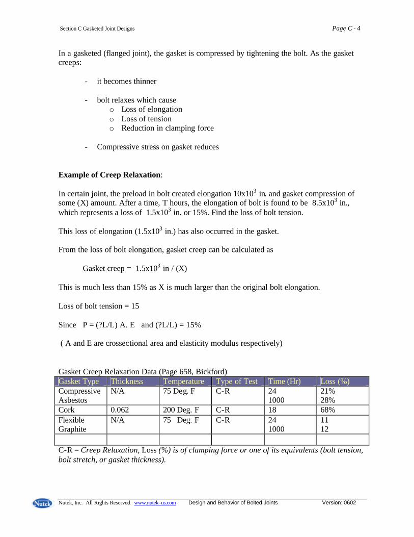
Section C Gasketed Joint Designs Page C - 4
Nutek, Inc. All Rights Reserved. www.nutek-us.com Design and Behavior of Bolted Joints Version: 0602
In a gasketed (flanged joint), the gasket is compressed by tightening the bolt. As the gasket creeps:
- it becomes thinner - bolt relaxes which cause
o Loss of elongation o Loss of tension o Reduction in clamping force
- Compressive stress on gasket reduces Example of Creep Relaxation: In certain joint, the preload in bolt created elongation 10x103 in. and gasket compression of some (X) amount. After a time, T hours, the elongation of bolt is found to be 8.5x103 in., which represents a loss of 1.5x103 in. or 15%. Find the loss of bolt tension. This loss of elongation (1.5x103 in.) has also occurred in the gasket. From the loss of bolt elongation, gasket creep can be calculated as Gasket creep = 1.5x10³ in / (X) This is much less than 15% as X is much larger than the original bolt elongation. Loss of bolt tension = 15 Since P = (?L/L) A. E and (?L/L) = 15% ( A and E are crossectional area and elasticity modulus respectively) Gasket Creep Relaxation Data (Page 658, Bickford) Gasket Type Thickness Temperature Type of Test Time (Hr) Loss (%) Compressive Asbestos
N/A 75 Deg. F C-R 24 1000
21% 28%
Cork 0.062 200 Deg. F C-R 18 68% Flexible Graphite
N/A 75 Deg. F C-R 24 1000
11 12
C-R = Creep Relaxation, Loss (%) is of clamping force or one of its equivalents (bolt tension, bolt stretch, or gasket thickness).

Section C Gasketed Joint Designs Page C - 5
Nutek, Inc. All Rights Reserved. www.nutek-us.com Design and Behavior of Bolted Joints Version: 0602
Factors that Affect Creep Cyclic Loading – Gasket s are found to creep more under cyclic loading than static loads. Material Plasticity – Plasticity in gasket material is desirable as it allows better mating with the flange surface and prevent leak. This means that some creep is desirable and unavoidable. Initial Thickness – Creep relaxation is directly proportional to the thickness. A 1/4 in thick flexible graphite gasket will relax about twice as much as a 1/8 in. thick gasket made of the same material. For design selection,
- a gasket should be as thick as it needs to be - but as thin as possible.
Note that ASTM F 38 B test reports creep data on 1/32 in thick gasket and must be modified for thicker gaskets. Initial Load – The amount of initial stress and preload on the gasket affects creep rate. Generally, higher load produces higher amount of creep. Time and Temperature – Most creep relation occurs in the first 15 – 20 minutes of the load application creep increases at higher temperature. Creep rates become very slow after 18 – 24 hours. Bolt Stiffness - The stiffness of the bolt does not have influence on gaskets creep-relaxation properties, however, it affects the relationship between loss of gasket thickness and the corresponding loss of clamping force. Long, flexible bolt will result in less loss of clamping force than a short, stubby bolt. GASKET STRENTH - The P x T Factor Gasket must have proper strength (tensile and crushing) to resist being torn apart blown out of the joint. Blowout resistance of a given gasket material is measured by clamping a test gasket between a pair of flanges and then subjecting it to higher pressure and temperature. Typically gasket and flange assembly is heated to certain level of temperature then the contained pressure is increased until blowout occurs. Every material is found to withstand a certain level of service temperature and pressure. After several such tests, a (P x T) rating is assigned to the gasket. A gasket material with temperature limit of 300 Deg. F and a contained pressure limit of 1000 psi may not operate when both are at their limits. If the P x T value for
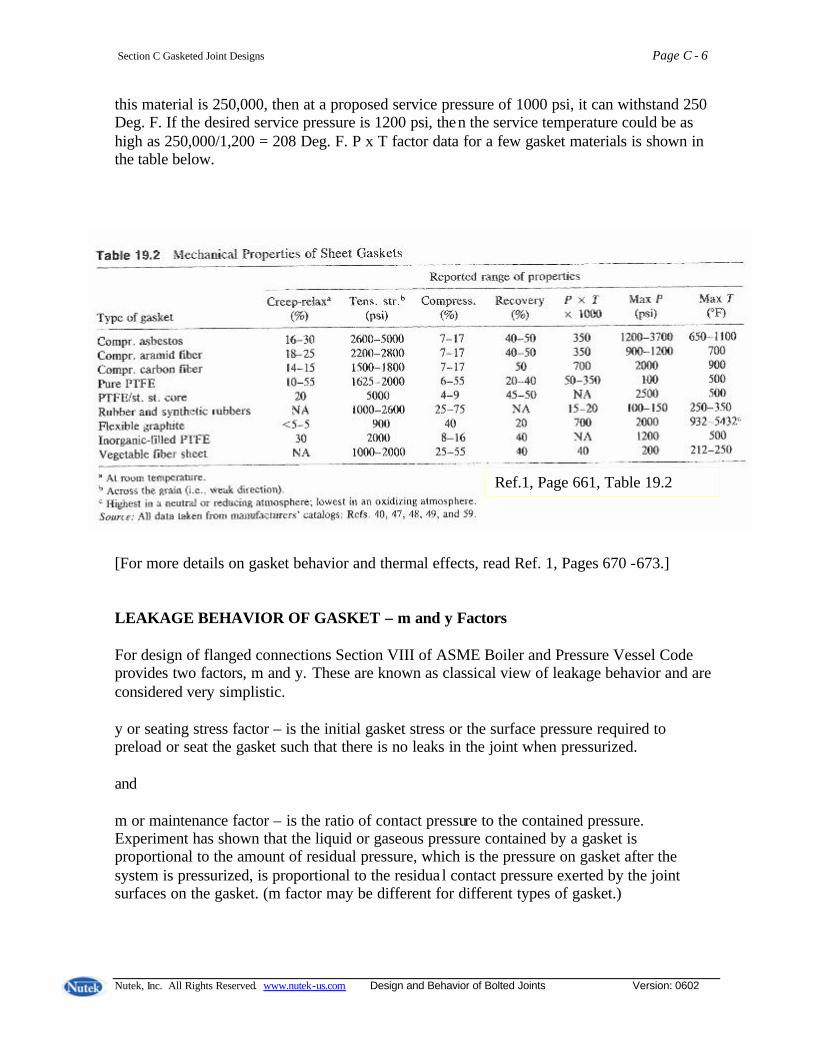
Section C Gasketed Joint Designs Page C - 6
Nutek, Inc. All Rights Reserved. www.nutek-us.com Design and Behavior of Bolted Joints Version: 0602
this material is 250,000, then at a proposed service pressure of 1000 psi, it can withstand 250 Deg. F. If the desired service pressure is 1200 psi, then the service temperature could be as high as 250,000/1,200 = 208 Deg. F. P x T factor data for a few gasket materials is shown in the table below. [For more details on gasket behavior and thermal effects, read Ref. 1, Pages 670 -673.] LEAKAGE BEHAVIOR OF GASKET – m and y Factors For design of flanged connections Section VIII of ASME Boiler and Pressure Vessel Code provides two factors, m and y. These are known as classical view of leakage behavior and are considered very simplistic. y or seating stress factor – is the initial gasket stress or the surface pressure required to preload or seat the gasket such that there is no leaks in the joint when pressurized. and m or maintenance factor – is the ratio of contact pressure to the contained pressure. Experiment has shown that the liquid or gaseous pressure contained by a gasket is proportional to the amount of residual pressure, which is the pressure on gasket after the system is pressurized, is proportional to the residua l contact pressure exerted by the joint surfaces on the gasket. (m factor may be different for different types of gasket.)
Ref.1, Page 661, Table 19.2
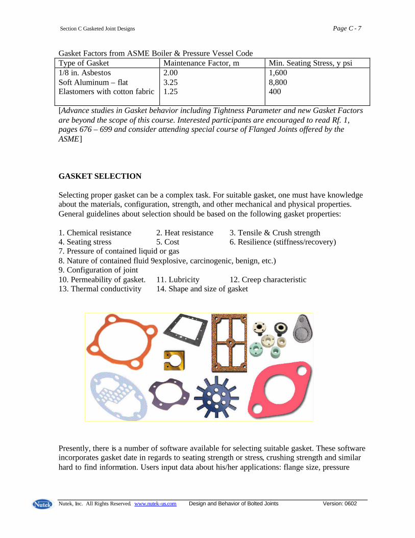
Section C Gasketed Joint Designs Page C - 7
Nutek, Inc. All Rights Reserved. www.nutek-us.com Design and Behavior of Bolted Joints Version: 0602
Gasket Factors from ASME Boiler & Pressure Vessel Code Type of Gasket Maintenance Factor, m Min. Seating Stress, y psi 1/8 in. Asbestos Soft Aluminum – flat Elastomers with cotton fabric
2.00 3.25 1.25
1,600 8,800 400
[Advance studies in Gasket behavior including Tightness Parameter and new Gasket Factors are beyond the scope of this course. Interested participants are encouraged to read Rf. 1, pages 676 – 699 and consider attending special course of Flanged Joints offered by the ASME] GASKET SELECTION Selecting proper gasket can be a complex task. For suitable gasket, one must have knowledge about the materials, configuration, strength, and other mechanical and physical properties. General guidelines about selection should be based on the following gasket properties: 1. Chemical resistance 2. Heat resistance 3. Tensile & Crush strength 4. Seating stress 5. Cost 6. Resilience (stiffness/recovery) 7. Pressure of contained liquid or gas 8. Nature of contained fluid 9explosive, carcinogenic, benign, etc.) 9. Configuration of joint 10. Permeability of gasket. 11. Lubricity 12. Creep characteristic 13. Thermal conductivity 14. Shape and size of gasket Presently, there is a number of software available for selecting suitable gasket. These software incorporates gasket date in regards to seating strength or stress, crushing strength and similar hard to find information. Users input data about his/her applications: flange size, pressure
Section C Gasketed Joint Designs Page C - 8
Nutek, Inc. All Rights Reserved. www.nutek-us.com Design and Behavior of Bolted Joints Version: 0602
ratings, gasket contact area, bolt length, service temperature and pressure, the type of fluid to be contained, type of bolt, etc. Such software program out put includes:
• Recommendation for seating stress (including assembly torque) • Total clamping force the torque will generate on the flange • Working stress on the gasket • Maximum allowable gasket stress • Gasket crushing strength • Etc.
SIMPLISTIC DESIGN ASSMEBLY GUIDELINES What toque should one use for assembly?
• Determine the bolt’s yield strength • Find the crushing strength of the gasket (in terms of bolt stress) • Use smaller of the above two to compute assembly torque. (This method ignores thermal expansion, flange rotation, stress corrosion, etc.)
Other known practice include:
• Use of the y factor for the gasket, which gives minimum seating stress, obtained from ASME Code or from gasket manufacturer to compute torque
• Calculate toque from a table of “allowable stress” from the Code
Safety Check – Before proceeding with the assembly, divide the desired force by the “tensile stress area” of the bolt to assure that the stress is below the yield strength of the bolt at service temperature. Calculate torque using: T = K D F in. lb.
Where D = nominal diameter of bolt (in) F = target preload (lb) K = Nut factor (dimensionless, steel on steel = 0.2)

Section C Gasketed Joint Designs Page C - 9
Nutek, Inc. All Rights Reserved. www.nutek-us.com Design and Behavior of Bolted Joints Version: 0602
Topics Group Exercises
Gasketed Joint C-1
a: A gasket materials has a P x T factors as 280,000. Determine:
(i) Maximum acceptable service pressure when the service temperature is 280 Deg. F (ii) Allowable service temperature if the service pressure needs to be 1,200 psi.
Gasketed Joints
b: Determine the assembly torque for a gasketed joint of the following description. 4 steel bolts, ½ in. dia, Yield stress = 35,000 psi. Gasket area = 3.5 Sq. in., Crushing strength of gasket = 9,200 psi.
(Use T = K D F, with K = 0.30 for stainless steel bolts.)

Section C Gasketed Joint Designs Page C - 10
Nutek, Inc. All Rights Reserved. www.nutek-us.com Design and Behavior of Bolted Joints Version: 0602
GASKETED FLANGED JOINT DESIGN The purpose of the flanged joint is mainly to join two section of the pipe, seal ends of tubes, or cover containers of various shapes. Although most flanged joints are circular, as shown for piping joints, rectangular and shapes of complex nature for va lve, turbine, engine cylinder heads of internal combustion engines, are common. The fluid contained in such joined devices may be gas or liquid, which may be stationary or flow at high speed, and at wide ranging pressure and temperature (External or internal pressure range: vacuum to very high, temperature rage: cryogenic to 1000oC). The common objective in all these applications is to control the leakage. Flanged joints can be of two types:
- with gasket - without gasket (metal to metal contact for sealing)
Objectives and Design Challenge For a given characteristics of the gasket, determine economical dimensions of the flanges and the bolts that assures a desired level of sealing. The sealing level desired is obtained when leakage is controlled within acceptable limit. Specific design goals are:
- Establish dimension of the flanges - Determine number of bolts & its tension (Prescribe torque necessary based on the
torque vs. tension relationship.) Types of Flanged Joints For most applications choosing the standard joint design is the most efficient approach. Standard flanges and gasket of corresponding sizes are readily available in the market place. The available standard joints are specified in detail in national standard like ASME B16.5, and international standard like ISO 7005. There are several designs of flanges available to suit applications of all kinds. The more common among the flange designs are shown below.

Section C Gasketed Joint Designs Page C - 11
Nutek, Inc. All Rights Reserved. www.nutek-us.com Design and Behavior of Bolted Joints Version: 0602
WELDING NECK FLANGE
• Common choice for heavy duty applications.
• Designed with a hub on the backside tapering to a diameter that will match the pipe.
• Flanges are bored to match the inside diameter of the mating pipe so there will be no restriction of product flow.
• Reinforced hub gives it an extra rotational stiffness.
LAPED PLATE FLANGE
• Flange rotation is mostly decoupled from the pipe end hub and the gasket.
• Used in applications where the joint must be frequently disassembled for cleaning or where there is a need to facilitate bolt alignment.
SLIP-ON WELD PLATE FLANGE
• Designed to slide over the outside diameter of the pipe.
• Flanges are attached to the pipe by fillet welding at the hub and at the end of the pipe inside the flange.
• Not normally used in high stress applications.
WELD-SOCKET PLATE FLANGE
• Similar to slip-on flanges except they have a bore diameter equal to that of the matching pipe.
• Have a counterbore from the hub side slightly larger than the outside diameter of the matching pipe which provides a "socket" into which the end of the pipe is inserted.
• Flange is attached to the pipe by a fillet weld at the hub.

Section C Gasketed Joint Designs Page C - 12
Nutek, Inc. All Rights Reserved. www.nutek-us.com Design and Behavior of Bolted Joints Version: 0602
Types of Gaskets Gaskets come in different shapes to suit the flange geometry and sealing requirements. Commercially available gaskets are made of different materials to satisfy different performance characteristics. Below is a product line from one manufacturer. • Adhesive Backed Gaskets • Felt Gaskets • Oil Resistant Gaskets • Automotive Gaskets • Flange Gaskets • Plastic Gaskets • Cork Gaskets • Foam Gaskets • Rubber Gaskets • Custom Gaskets • Gasket Material • Silicone Gaskets • Die Cut Gaskets • Gaskets • Sponge Rubber Gaskets • EPDM Gaskets • Neoprene Gaskets • Urethane Gaskets
Additionally, depending on how the gasket is utilized in the joint, it is grouped under different names.
Full-face gasket Controlled compression spiral wound gasket, centered off bolts
Controlled compression gasket, extending beyond bolt circle

Section C Gasketed Joint Designs Page C - 13
Nutek, Inc. All Rights Reserved. www.nutek-us.com Design and Behavior of Bolted Joints Version: 0602
Pressure = 0
½ Tb
½ Tb
½ Fg
½ Fg
Analysis of Flanged Joints – Simplified Model The taper-hub weld-neck flanges shown here, is coomonly used for high duty applications. In a simplified view , the flages, bolts and the gasket assmbly can be treated as linear springs. This would be the case when the flange rotation due to moment produced when the bolts are tightened, is ignored. Remember the goal of the gasketted joint is to make sure that the stress in the gasket is sufficient to keep the leak rate below an acceptable limit (no leak may not be a practical goal) From free-body diagram of flange, we find that when the joint is assembled, before the fluid in the tube/pipe is pressurized, we can write the an axial force equation for equilibrium condition:
Tb = Fg ----------- (Eq. C-01) Also the spring rates for the gasket and bolting can be expressed as follows. Axial stiffness f the bolting:
Kg = Eg Ag /Lg ----------- (Eq. C-02) Compressive stiffness of gasket
Kb = Eb Ab /Lb ----------- (Eq. C-03) The above is derived from the relationships of axial spring stiffness and stress vs. strain relation of material properties shown below. For axial spring,
F = K X or K = F/ X From stress and strain relation Stress (F/A) = E Strain (X/L) Or F = E A (X/L) Substituting F in the expression for K, K = E A (X/L) / X = EA/L

Section C Gasketed Joint Designs Page C - 14
Nutek, Inc. All Rights Reserved. www.nutek-us.com Design and Behavior of Bolted Joints Version: 0602
Pressure = P
½ Tb
½ Tb
½ Fg
½ Fg Fp
Where K =stiffness, X = Deflection, F = Force, L = Length, and E = Modulus of elasticity The stifnness values of gasket and bolting are key characteristics as they can be used readily to controll forces by controlling the displacement. Also from known values of area and the compressive stress limit of, say gasket, the allowable displacement can be detremined. Notations:
Tb = Force (Tension) in the bolts (lbf)
Ab = Crossectional area of the bolt (sq.in.)
Eb = Modulus of elasticity of bolt material (psi)
Lb = Effective clamp length of the bolt (inch)
Kb = Axial stiffness of the bolting (lbf/in)
Fg = Compressive force in the gasket (lbf)
Ag = Gasket contact area (sq.in.)
Eg = Modulus of elasticity of gasket at no load (psi)
Lg = Thickness of gasket (inch)
Kg = Compressive stiffness of gasket (lbf/in) P = Internal pressure (positive or negative, psi) Fp = Force due to pressure in the tube When the tube is pressurized, the equilibrium equation gives:
Tb = Fg + Fp ----------- (Eq. C-04) Design Steps:
1. From the pressure in the pipe and its geometry, force due to the pressure (Fp) can be calculated.
2. Based on the selected gasket (code) geometry and properties, force in the gasket (Fg) can be calculated.
After the gasket seating is pressurized, there would be a tendency to separate the joint and reduce the gasket seating stress. The operating bolt force must resist the separating pressure and maintain a sufficient gasket load to retain seal. As per the ASME Boiler and Pressure Vessel Code design rule, the bolt force component on the gasket (Fg) is also dependent on the pressure in the tube as per the following relation: Tb = Fg + Fp

Section C Gasketed Joint Designs Page C - 15
Nutek, Inc. All Rights Reserved. www.nutek-us.com Design and Behavior of Bolted Joints Version: 0602
Tb = (0.785Dg
2 P) + (2Wg x 3.14 Dg M P) (total load on the bolt) Where Dg = Gasket diameter, Wg = Effective width of the gasket, M = Gasket factor (experimentally determined) Note: Load required on the bolt is gasket area times pressure, plus presuure on TWO times the effective width of gasket times a gasket factor (M, constant). In reality, the gasket sealing will be affected by flange rotation and its rgidity which are ingnored in this calculation. 3. Total load in the bolt now can be calculated using Equation C-04 4. Based on the required bolt load, using the torque vs. tension relationship, the torque
necessary to obtain the tension can be calculated.
Tightening strategies and their preload accuracy are:
Torque: ±35% Torque-Angle: ±15% Torque-to-Yield: ± 7% Determine torque for achieving desired preload using the following equation: T=KDF (Torque = K factor x screw diameter x pounds of tension induced in bolt) For example, a 1/4"-20 socket screw with UNRC threads and a K factor of 0.21 has yield strength 5,073 lbs. minimum. Using 75% of that, 3,805 lbs, gives us the pounds of tension induced in the bolt. Consequently, our formula becomes: T = .21 x .25 x 3805, or T = 200 lbin
Standards and Codes for Flanged Joints The quickest and most efficient way to design the joint is to select the standard joint design. The details of the standard joints are specified in national standards like the ones shown below.
• ASME B16.5 – 1988, Steel Pipe Flanges and Flanged Fittings (Formerly ANSI B16.5 and then ASME/ANSI B16.5)
• International Standard ISO 7005, Metallic Flanges, Part 1:Steel Flanges. • ASME B16.47 – 1990, Large Diameter Steel Flanges: NPS 26 Through NPS 60.
The joint design codes provide procedures and steps that allow the user to design gasketed joint that is structurally sound and meets the leakage control specification. Through a series of formulas and charts, the code offers key data like:

Section C Gasketed Joint Designs Page C - 16
Nutek, Inc. All Rights Reserved. www.nutek-us.com Design and Behavior of Bolted Joints Version: 0602
• Dimension of flanges and bolt • Face details – dimension, finish, and permissible defects. • Bolt-hole templates • Weld geometry and dimensions. • Material specifications. • Ratings - maximum allowable non-shock pressure/temperature limits for each
size and duty class • Etc
Code Terminologies Standard flange designs are grouped based on their application suitability. On ASME B16.5, the joints are grouped in Class 150 (lightest duty design) through Class 2500 (heaviest duty designs. On the other hand, the international standard ISO 7005 categorizes the flange designs in PN 2.5, the light duty, to PN 420 for the heaviest duty designs. Flange design for ASME Class 150 is shown below Threaded Flange 1/2" through 24" NPS Class 150 through 1500 (to 12" NPS max. for Class 2500) (Larger Sizes available on request)
Threaded Pipe Flanges - Class 150
Nom. Pipe Size
Flange Dia. (0)
Flange Thick
(Q) Hub Dia. At Base
(X) Raised
Face Dia. (RF)
No. Hole
Dia. Bolts
Dia. Of Bolt Circle
(BC) Length
thru Hub (L)
Thread Length
(T) 1/2 3-1/2 7/16 1-3/16 1-3/8 4 1/2 2-3/8 5/8 5/8 3/4 3-7/8 1/2 1-1/2 1-11/16 4 1/2 2-3/4 5/8 5/8 1 4-1/4 9/16 1-15/16 2 4 1/2 3-1/8 11/16 11/16
1-1/4 4-5/8 5/8 2-5/16 2-1/2 4 1/2 3-1/2 13/16 13/16 1-1/2 5 11/16 2-9/16 2-7/8 4 1/2 3-7/8 7/8 7/8
2 6 3/4 3-1/16 3-5/8 4 5/8 4-3/4 1 1 2-1/2 7 7/8 3-9/16 4-1/8 4 5/8 5-1/2 1-1/8 1-1/8
3 * 7-1/2 15/16 4-1/4 5 4 5/8 6 1-3/16 1-3/16 3-1/2 8-1/2 15/16 4-13/16 5-1/2 8 5/8 7 1-1/4 1-1/4
4 9 15/16 5-5/16 6-3/16 8 5/8 7-1/2 1-5/16 1-5/16 5 10 15/16 6-7/16 7-5/16 8 3/4 8-1/2 1-7/16 1-7/16 6 11 1 7-9/16 8-1/2 8 3/4 9-1/2 1-9/16 1-9/16 8 13-1/2 1-1/8 9-11/16 10-5/8 8 3/4 11-3/4 1-3/4 1-3/4 10 16 1-3/16 12 12-3/4 12 7/8 14-1/4 1-15/16 1-15/16
12 19 1-1/4 14-3/8 15 12 7/8 17 2-3/16 2-3/16

Section C Gasketed Joint Designs Page C - 17
Nutek, Inc. All Rights Reserved. www.nutek-us.com Design and Behavior of Bolted Joints Version: 0602
14 21 1-3/8 15-3/4 16-1/4 12 1 18-3/4 2-1/4 2-1/4 16 23-1/2 1-7/16 18 18-1/2 16 1 21-1/4 2-1/2 2-1/2 18 25 1-9/16 19-7/8 21 16 1-1/8 22-3/4 2-11/16 2-11/16 20 27-1/2 1-11/16 22 23 20 1-1/8 25 2-7/8 2-7/8 24 32 1-7/8 26-1/8 27-1/4 20 1-1/4 29-1/2 3-1/4 3-1/4
* Data used for example calculation shown below.
ANSI/ASME B16.5-1996 Class 150
Pipe Size Outside Diameter Inside Diameter Number of Bolt
Holes Bolt Hole Diameter Bolt Circle
1/2" 3-1/2 0.88 4 5/8 2-3/8
3/4" 3-7/8 1.09 4 5/8 2-3/4
1" 4-1/4 1.36 4 5/8 3-1/8
1-1/4" 4-5/8 1.70 4 5/8 3-1/2
1-1/2" 5 1.95 4 5/8 3-7/8
2" 6 2.44 4 3/4 4-3/4
2-1/2" 7 2.94 4 3/4 5-1/2
3" 7-1/2 3.57 4 3/4 6
3-1/2" 8-1/2 4.07 8 3/4 7
4" 9 4.60 8 3/4 7-1/2
5" 10 5.66 8 7/8 8-1/2
6" 11 6.72 8 7/8 9-1/2
8" 13-1/2 8.72 8 7/8 11-3/4
10" 16 10.88 12 1 14-1/4
12" 19 12.88 12 1 17
14" 21 14.14 12 1-1/8 18-3/4
16" 23-1/2 16.16 16 1-1/8 21-1/4
18" 25 18.18 16 1-1/4 22-3/4
20" 27-1/2 20.20 20 1-1/4 25
24" 32 24.25 20 1-3/8 29-1/2
Note: This table is intended for estimating purposes only. Refer to the ASME B16.5-1996 standard for complete engineering and applications information. All dimensions are in inches unless otherwise noted. Inside diameter and thickness dimensions are application specific. Recommended bolts are 1/8" smaller than the nominal bolt hole diameters shown.
Section C Gasketed Joint Designs Page C - 18
Nutek, Inc. All Rights Reserved. www.nutek-us.com Design and Behavior of Bolted Joints Version: 0602
Example Flange Joint Design Consider a Class 150 3 in. diameter tube from the table above subjected to 250 psi. Bolts: 5/8 in. dia, 4 bolts (Gasket width is obtained from RF data in the Table in page C-7) Gasket width: ( 5.00 – 3) = 2 in., Effective width = 2.0 x 0.5 = 1.00 in. Gasket Dia: 3 + 1.0 = 4.00 in. M (gasket factor) =1.0 Then, the total load on 4 bolts
Tb = (0.785Dg2 P) + (2Wg x 3.14 Dg M P)
Tb = (0.785 x 4.002 x 250) + (2 x 0.625 x 3.14 x 4.00 x1 x 250) = 3,140 + 3,925 = 7,065 lbs. (tension in bolts, F in toque vs. tension formula) Tension in each of the four bolts = 7,065 /4 = 1, 766 lbf. Assembly Torque: Assuming, Nut factor, K =0.25, T = KDF Or Torque required, T = 0.25 x (5/8) x 1,766 = 276 in. lb.
Section C Gasketed Joint Designs Page C - 19
Nutek, Inc. All Rights Reserved. www.nutek-us.com Design and Behavior of Bolted Joints Version: 0602
Topics Group Exercises
Flange Joint C-2
a: Specify bolt torque required in a flanged joint to keep the leakage within limit. Use a class 150 threaded flanges to connect two 5 in. diameter pipes carrying steam at 225 psi.. (Assume gasket factor, M = 1 and nut factor, K = 0.27) Hint: See example at page C-9, use Table at page C-7 for 5 in dia. pipes .)
Flange Joints
b: Design a joint using class 150 threaded flanges to connect two 2 in. diameter pipes carrying steam at 300 psi. Specify the torque required for the bolts to keep the leakage within limit. (Assume gasket factor, M = 1 and nut factor, K = 0.32, 4 5/8 dia. bolts) Hint: See example at page C-9, use Table at page C-7 for 2 in dia. pipes .)

Nutek, Inc. All Rights Reserved. www.nutek-us.com Design and Behavior of Bolted Joints Version: 0602
Section – D Causes and Prevention of Bolt Failure
Corrosion Effect of Corrosion
- accelerates mechanical failure like fatigue and thread stripping
- initial buildup of corrosion/rust. Can increase tension in bolts (increased joint dim.).
- excessive corrosion can lead to total loss of clamping load as joint weakens.
- It could cause sudden/unexpected loss of clamping force due to mechanism of hydrogen embrittlement or stress corrosion cracking.
Science of Corrosion ALL METALS have electrical potential which • Depend on atomic structure
• Indicates how easily it gives out or absorbs electron Analogy For water trapped in higher elevation in the mountain, potential energy available is dependent on the height of the lake. *Elevation = Electrical potential Elevation determines which way the water flows.
Direction of water flow

Section D Causes and Prevention of Bolt Failure Page D - 2
R. Roy/Nutek, Inc. All Rights Reserved www.nutek-us.com Design and Behavior of Bolted Joints Updated: Dec. 2005
Anodic materials – gives out electrons more readily Cathodic materials – absorbs electron more readily
• Anodic and Cathodic are relative terms. • No material can be just anodic or Cathodic. • Any material can serve either function.
An electrical battery is formed when two metals of different electrical potentials are connected by a conductor and a liquid. Under this condition MORE ANODIC OF THE TWO METALS WILL CORRODE.
E Electrical Battery A – Anodic metal, C = Cathodic material
Anode rusts
Electrolyte A C Anode Cathode
_
_
Example: Steel (anode) in presence of Brass (cathode)
But Steel (cathode) in presence of Magnesium (anode ) Anode – gives electron Away Cathode – Collects electron
_
_ _

Section D Causes and Prevention of Bolt Failure Page D - 3
R. Roy/Nutek, Inc. All Rights Reserved www.nutek-us.com Design and Behavior of Bolted Joints Updated: Dec. 2005
Depending on the electronic potential, metals are arranged in a galvanic series table. ANODIC – Most likely to corrode (least noble).
• Magnesium • Zinc • Aluminum 1100 • Cadmium
• Aluminum 2024-T4 • Steel Iron • Cast iron • Chromium iron (active)
Higher location on the mountain indicates higher electrical potential (ANODIC) – more likely * Nickel resist cast iron to lose electrons * Types 304 and 316 stainless steel (active) and Corrode * Tin
* Nickel (active)
* Inconel (active) * Hastelloy Alloy C (Active)
Active – easily gives out electrons * Brasses * Copper Passive – Less likely to lose electrons * Bronzes (Due to an oxide layer.)
• Monel nickel • Nickel (passive)
• Silver • Titanium • Graphite • Gold
ANODIC – Most likely to corrode (Least Noble) CATHODIC- Least likely to corrode (Most Noble)
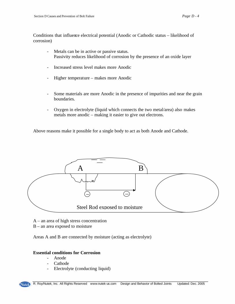
Section D Causes and Prevention of Bolt Failure Page D - 4
R. Roy/Nutek, Inc. All Rights Reserved www.nutek-us.com Design and Behavior of Bolted Joints Updated: Dec. 2005
Conditions that influence electrical potential (Anodic or Cathodic status – likelihood of corrosion)
- Metals can be in active or passive status. Passivity reduces likelihood of corrosion by the presence of an oxide layer
- Increased stress level makes more Anodic
- Higher temperature – makes more Anodic
- Some materials are more Anodic in the presence of impurities and near the grain boundaries.
- Oxygen in electrolyte (liquid which connects the two metal/area) also makes
metals more anodic – making it easier to give out electrons. Above reasons make it possible for a single body to act as both Anode and Cathode. A – an area of high stress concentration B – an area exposed to moisture Areas A and B are connected by moisture (acting as electrolyte) Essential conditions for Corrosion
- Anode - Cathode - Electrolyte (conducting liquid)
A B
Steel Rod exposed to moisture

Section D Causes and Prevention of Bolt Failure Page D - 5
R. Roy/Nutek, Inc. All Rights Reserved www.nutek-us.com Design and Behavior of Bolted Joints Updated: Dec. 2005
- Metallic connection A body will only CORRODE when it is connected to another metal of different electrical potential and both are immersed or wetted by some solution (forms miniature batteries). Anode in the battery provides electrons, which flow to cathode. In this process the anode is gradually destroyed/corrodes. The cathode, on the other hand, collects electrons/materials, which plates out on its surface. Two Metal Corrosion
Corrosion is inevitable when two metals are different and connected together in the presence of a fluid. Example: Steel bolts on Aluminum towers exposed to seawater. The likelihood or severity of corrosion depends on how far apart the two metals are in the galvanic Series.
Anode Cathode Loses Materials Corrodes Gains Materials

Section D Causes and Prevention of Bolt Failure Page D - 6
R. Roy/Nutek, Inc. All Rights Reserved www.nutek-us.com Design and Behavior of Bolted Joints Updated: Dec. 2005
Single Metal/Part Corrosion
Stress Conc. Water droplet Broken oxide film makes Localized area more anodic Stress Corrosion cracking Fretting Corrosion Crevice Corrosion Rubbing of oxide coated bodies. Loss of coating – becomes ANODIC Water C A C A Anodic due to A – Stressed /anodic To stress C – Cathodic surface
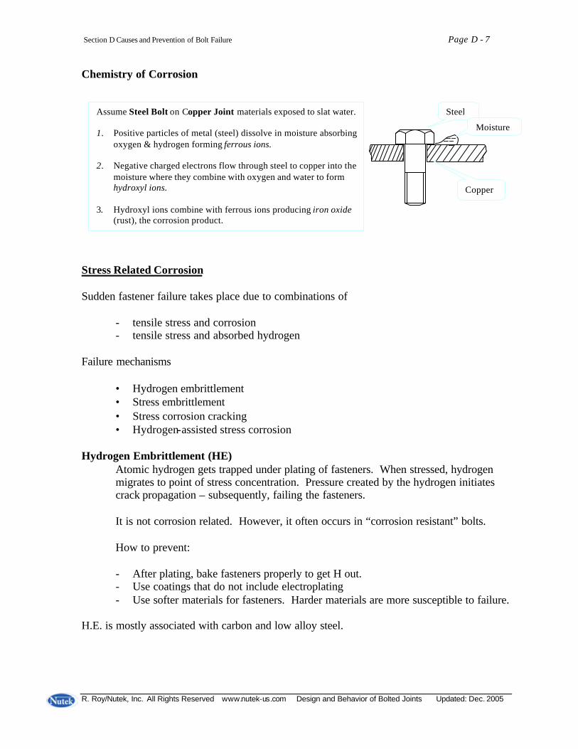
Section D Causes and Prevention of Bolt Failure Page D - 7
R. Roy/Nutek, Inc. All Rights Reserved www.nutek-us.com Design and Behavior of Bolted Joints Updated: Dec. 2005
Chemistry of Corrosion Stress Related Corrosion Sudden fastener failure takes place due to combinations of
- tensile stress and corrosion - tensile stress and absorbed hydrogen
Failure mechanisms
• Hydrogen embrittlement • Stress embrittlement • Stress corrosion cracking • Hydrogen-assisted stress corrosion
Hydrogen Embrittlement (HE)
Atomic hydrogen gets trapped under plating of fasteners. When stressed, hydrogen migrates to point of stress concentration. Pressure created by the hydrogen initiates crack propagation – subsequently, failing the fasteners. It is not corrosion related. However, it often occurs in “corrosion resistant” bolts. How to prevent: - After plating, bake fasteners properly to get H out. - Use coatings that do not include electroplating - Use softer materials for fasteners. Harder materials are more susceptible to failure.
H.E. is mostly associated with carbon and low alloy steel.
Assume Steel Bolt on Copper Joint materials exposed to slat water. 1. Positive particles of metal (steel) dissolve in moisture absorbing
oxygen & hydrogen forming ferrous ions. 2. Negative charged electrons flow through steel to copper into the
moisture where they combine with oxygen and water to form hydroxyl ions.
3. Hydroxyl ions combine with ferrous ions producing iron oxide
(rust), the corrosion product.
Steel
Moisture
Copper

Section D Causes and Prevention of Bolt Failure Page D - 8
R. Roy/Nutek, Inc. All Rights Reserved www.nutek-us.com Design and Behavior of Bolted Joints Updated: Dec. 2005
Strategies for Corrosion Reduction Philosophy : Eliminate condition that forms corrosion “battery”. Remove one or more of the four necessary conditions/ingredients for the battery to function. 1. The anode, 2. The cathode, 3. Electrolyte, and 4. The metallic connection between the anode and the cathode. Commonly suggested design tips:
1. Keep joints dry. Provide drainage or remove electrolyte. 2. Select fastener material that is closer in the galvanic series. (Use Brass or Bronzes
for Copper). Better design practice is to use identical material.
3. Since anode is destroyed in corrosion, design it to have larger dimension. 4. Break the metallic connection between the two parts by insulation (paint, coatings,
gasket, and spacers).
5. Include a third sacrificial anode, which reverses the flow of current in the battery.
Galvanic Series Aluminum . . Steel . . Brass
Steel Bolt Aluminum plate Sacrificial ANODE corrodes and destroyed (replaced) Brass joint member

Section D Causes and Prevention of Bolt Failure Page D - 9
R. Roy/Nutek, Inc. All Rights Reserved www.nutek-us.com Design and Behavior of Bolted Joints Updated: Dec. 2005
6. Attach an external battery in opposite polarity. 7. Seal cracks and crevices (paint, putty, and plastic washers). 8. Reduce stress concentrations by designing FILLETS, POLISHED or SHOT
PINNING SURFACES, distribute load evenly, avoid bending load, use conical/crowned washers.…
9. Use inhibitors in electrolyte, which retards its capacity to transport electrons. 10. Use materials that resist electrolyte. Industrial Fastener Institute (IFI) publishes
list of materials with resistance to different solution/materials. Example : Type 304 stainless steel has excellent resistance to fresh water, wine, sulfur, turpentine. It has poor resistance to sulfuric acid or zinc chloride.
11. When none of the above can be implemented, consider replacing the bolt periodically.
Section D Causes and Prevention of Bolt Failure Page D - 10
R. Roy/Nutek, Inc. All Rights Reserved www.nutek-us.com Design and Behavior of Bolted Joints Updated: Dec. 2005
Combating Corrosion Most fasteners are typically highly stressed, intricate, and small parts. Even a slight corrosive attack can cause detrimental effect on such parts. Therefore, proper measures must be taken to guard against corrosion by using special materials, coatings, and finishes. Use fasteners made of corrosion-resistant materials: Industry Materials preferred
• Aerospace → Titanium, Inconel * Automotive → Aluminum, plastics * Marine → Monel, Silicon Bronze * Petrochemical → Stainless Steel (all kinds)
Coatings of Fasteners Coating fasteners to reduce corrosion is most common. (90% of all carbon steel bolts are coated). Coating resists corrosion by
- providing a barrier which isolate bolt from the corrosive environment - including “passivation/inhibition” that slows down the corrosion process - acting as “galvanic” or sacrificial layer that can reverse the direction of the current
in the battery.

Section D Causes and Prevention of Bolt Failure Page D - 11
R. Roy/Nutek, Inc. All Rights Reserved www.nutek-us.com Design and Behavior of Bolted Joints Updated: Dec. 2005
Coating Quality and Side Effects Quality -
For barrier protection, coating must be perfect. A slight break in coating (paint, cad plating,…) can create a localized anodic region that will create a battery. Sacrificial coating need not be perfect.
Side Effects - Impact on bolt performance Coatings may be used to produce many desirable effects
- reduces friction between thread, collar and the part - reduces torque necessary to overcome frictional drag - good coatings reduce variability of friction and improve torque-tension
relationship - change appearance of fasteners, matching colors to hide it. Or even make
fasteners stand out as design accents. (Non-structural purpose)
Common Types of Coating
Organic Coating
• Made from plant or animal matters. • Contain carbon compounds • Can provide twice the corrosion protection of things such as cadmium and zinc
plating. They also come in different colors. • Eliminates (not present) hydrogen embrittlement
Application method – dip, spin, spray, paint.

Section D Causes and Prevention of Bolt Failure Page D - 12
R. Roy/Nutek, Inc. All Rights Reserved www.nutek-us.com Design and Behavior of Bolted Joints Updated: Dec. 2005
Paints (organic):
Alkyd and phenolic paints were popular before. Fluorocarbons and other polymers are used now. Zinc-rich paint is used for structural steel where entire joint, rather than bolt alone, is pained.
Phos-oil coating (organic):
Mild acids like zinc phosphate and manganese phosphate in a tumble bath gives the bolt a porous surface which provides an excellent base for retention of oils, waxes or other lubricants. Phosphate + oil Phosphate + paint + oil Common practices Phosphate + zinc rich paint
Solid Film Organic Coatings: Produce “a thin layer of slippery paint”. Teflon-S Stalgard Used on Xylan Trade → * Carbon Steel Emralon names * Stainless Steel Everlube * Aluminum ↑ Fluorocarbons
Chemicals → Molybdenum disulfide, graphite, or polytetrafluoroethylelne (PTFE)
In general the above organic fluorocarbons can be used in applications which involve changes in temperature. -450°F (-268° C) to 400° F (+204° C)
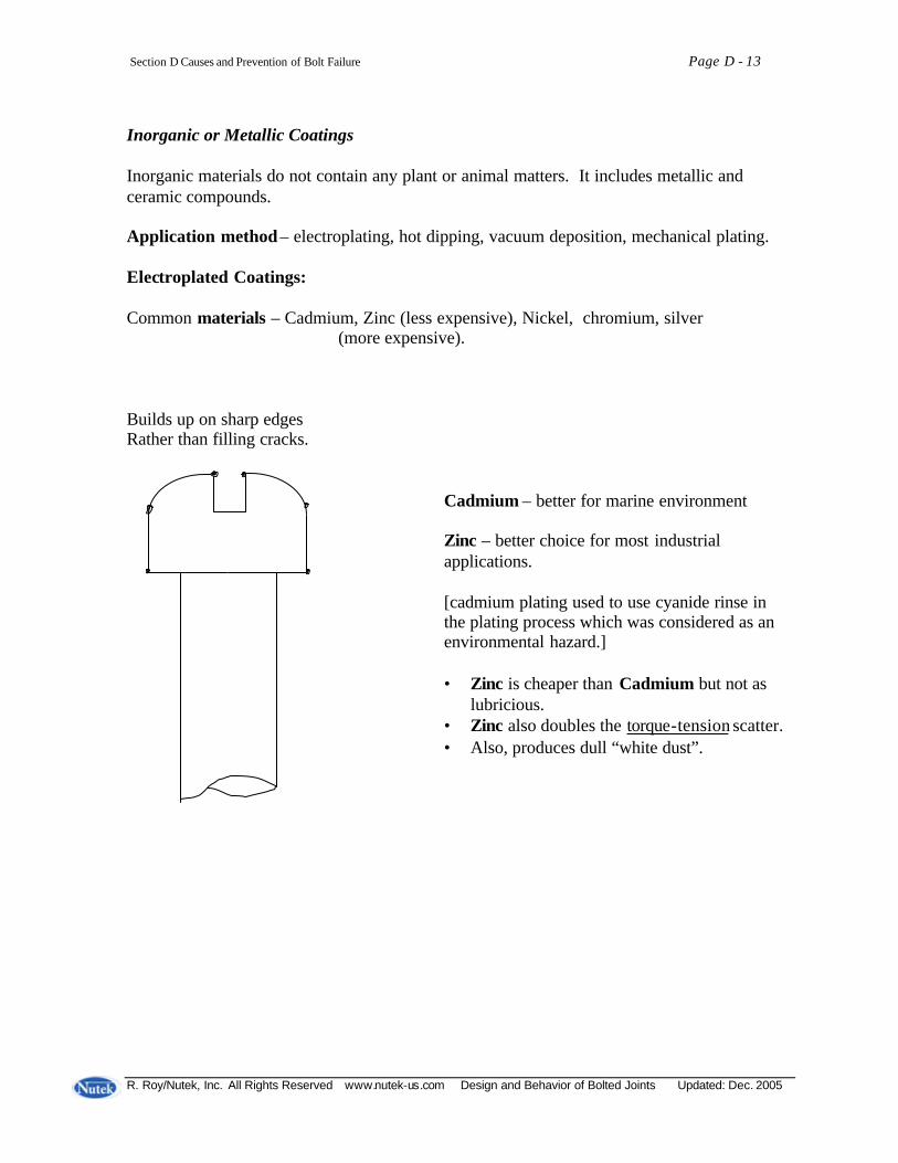
Section D Causes and Prevention of Bolt Failure Page D - 13
R. Roy/Nutek, Inc. All Rights Reserved www.nutek-us.com Design and Behavior of Bolted Joints Updated: Dec. 2005
Inorganic or Metallic Coatings Inorganic materials do not contain any plant or animal matters. It includes metallic and ceramic compounds. Application method – electroplating, hot dipping, vacuum deposition, mechanical plating. Electroplated Coatings: Common materials – Cadmium, Zinc (less expensive), Nickel, chromium, silver (more expensive). Builds up on sharp edges Rather than filling cracks. Cadmium – better for marine environment
Zinc – better choice for most industrial applications. [cadmium plating used to use cyanide rinse in the plating process which was considered as an environmental hazard.] • Zinc is cheaper than Cadmium but not as
lubricious. • Zinc also doubles the torque-tension scatter. • Also, produces dull “white dust”.

Section D Causes and Prevention of Bolt Failure Page D - 14
R. Roy/Nutek, Inc. All Rights Reserved www.nutek-us.com Design and Behavior of Bolted Joints Updated: Dec. 2005
Hot Dip Coatings Two materials are applied this way. Aluminum – fasteners coated with aluminum are called “aluminized” Zinc – Zinc coated fasteners are called “galvanized”.
• Inexpensive, used for high-strength fasteners like ASTM A325 structural steel bolts (often galvanized).
• The hot dip process is difficult to control – resulting in thickness variation.
Threads are undercut to provide room for coating – but needs to be recut with a tap or due after coating has been applied.
• Lower stripping strength (thread) than mechanically galvanized one, but more
corrosion resistance (greater thickness). Mechanical Plating
In these process ductile metals such as zinc, cadmium, or tin are cold-welded onto the metal substrate by mechanical energy. Fasteners that mechanically plated with zinc are called “mechanically galvanized”.
Mechanically plating VS Electro-plating Hot dipping • Uniform coating thickness * Thicker and non-uniform • Absence of hydrogen embrittlement * hydrogen embrittlement present • Tempering – absent. * Detempering may be needed No detempering needed • Higher durability out of newer * Not done process which combines aluminum and zinc for coating threads. ½ mil thickness. No need for retap.
• Phosphate coating over zinc & * NA aluminum has been seen to provide better corrosion resistance.
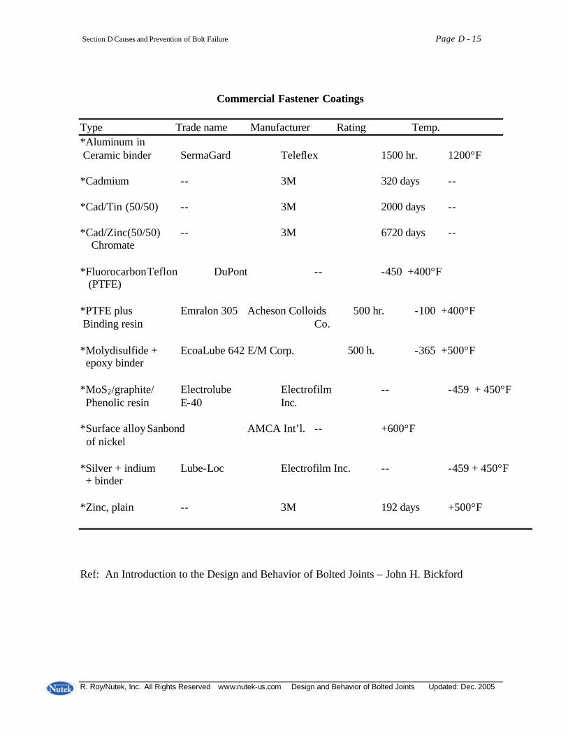
Section D Causes and Prevention of Bolt Failure Page D - 15
R. Roy/Nutek, Inc. All Rights Reserved www.nutek-us.com Design and Behavior of Bolted Joints Updated: Dec. 2005
Commercial Fastener Coatings
Type Trade name Manufacturer Rating Temp. *Aluminum in Ceramic binder SermaGard Teleflex 1500 hr. 1200°F *Cadmium -- 3M 320 days -- *Cad/Tin (50/50) -- 3M 2000 days -- *Cad/Zinc(50/50) -- 3M 6720 days -- Chromate *Fluorocarbon Teflon DuPont -- -450 +400°F (PTFE) *PTFE plus Emralon 305 Acheson Colloids 500 hr. -100 +400°F Binding resin Co. *Molydisulfide + EcoaLube 642 E/M Corp. 500 h. -365 +500°F epoxy binder *MoS2/graphite/ Electrolube Electrofilm -- -459 + 450°F Phenolic resin E-40 Inc. *Surface alloy Sanbond AMCA Int’l. -- +600°F of nickel *Silver + indium Lube-Loc Electrofilm Inc. -- -459 + 450°F + binder *Zinc, plain -- 3M 192 days +500°F Ref: An Introduction to the Design and Behavior of Bolted Joints – John H. Bickford

Section D Causes and Prevention of Bolt Failure Page D - 16
R. Roy/Nutek, Inc. All Rights Reserved www.nutek-us.com Design and Behavior of Bolted Joints Updated: Dec. 2005
Miscellaneous Coating Processes Ion Vapor Deposition (IVD) – High-strength steel and titanium are coated with aluminum using this process:
• High resistance to stress corrosion cracking High purity Nickel coating – This material is alloyed with carbon or alloy steel fasteners
• Good resistance to Severe acid and alkalines • No buildup • Allows additional coating of zinc or cadmium to enhance corrosion protection and
increase lubricity. Composite Coating: Mixed – organic and inorganic materials Corrosion Resistance Rating ASTM B117 procedure – expressed in hours before significant damage by salt spray. [Salt may not be your concern]

Section D Causes and Prevention of Bolt Failure Page D - 17
R. Roy/Nutek, Inc. All Rights Reserved www.nutek-us.com Design and Behavior of Bolted Joints Updated: Dec. 2005
Modes of Joint Failure The main function of a bolt is to clamp two or more joint members together. The objective of the assembly function/process is to introduce tension in the bolt that produces clamping force. A joint is considered to have failed when there is loss of claming force in the bolt. There are a number of ways that bolts can lose the clamping force and the joint fail. a. Mechanical Failure of the bolt
- too much tension during installation (excessive torque applied). (This should never happen if the joint is designed* right)
- Mechanical failure due to elevated temperature - Corrosion destroyed the bolt - Stress corrosion cracking failure - Fatigue failure
*Design refers to proper material, quality, dimension, heat treatment, application specs. Etc.
• Poor heat treatment in low cost bolt – head may be pulled off.
• Bolt head welded to threaded rod –
• Bolt designed without proper fillet radii-.
b. Stripping of Threads Threads may strip when proper contact and shear resistance area is reduced. This would generally happen when thread geometry is too far from the standard (ANSI B.1.1) -–pitch diameter of thread. Say: Nominal pitch Dia = .5889(pd) Tolerance = +0 - .0035 If the nut is at nominal, but the bolt is at minimum dia. allowed by the standard, this bolt will have 15% less thread strength. The thread strength goes down to 50% when bolt p.d. is lowered by 20 mils.
- flank angle - tapered bolt and/or nut
- irregular helix angle →
- out-of-round bolt/nut.

Section D Causes and Prevention of Bolt Failure Page D - 18
R. Roy/Nutek, Inc. All Rights Reserved www.nutek-us.com Design and Behavior of Bolted Joints Updated: Dec. 2005
c. Lost Bolts (self-loosened) There can be no clamp load when the bolt is absent. A common cause of missing bolt is a phenomenon called self- loosening caused by:
- Vibration - Temperature and pressure cycle
- Reversing loads in a direction right angle to bolt axis
- Carelessness - Not installed due to hole misalignment - Not installed as considered overdesigned.
p.d Nominal min. p.d. Tapered thread Out-of-round

Section D Causes and Prevention of Bolt Failure Page D - 19
R. Roy/Nutek, Inc. All Rights Reserved www.nutek-us.com Design and Behavior of Bolted Joints Updated: Dec. 2005
d. Loose Bolts Bolt not having appropriate tension is quite common. Loose bolts may cause “self- loosening” or Vice versa. The resulting failures are:
- Joint leakage - Joint slip - Cramping of machine members (viz. bearing misaligned) - Fatigue failure - Self- loosening
e. Bolts Too Tight
Excessive bolt tension/load can cause:
- Crushed gasket - Damaged joint surface (galling
- Encourage stress corrosion cracking
Which Failure Mode should we be concerned about? It depends on the industry segment/type of applications. Auto: - self- loosening - corrosion - leakage (head gasket) - vibration loosening Petrochemical: - leakage from gasket - corrosion Structural Steel Industry - joint slip - corrosion - fatigue Aerospace: - fatigue
Conditions for Failure Each type of failure is initiated by a limited number of “essential conditions” Corrosion: - An anode - A cathode - An electrolyte - A metallic connection
between anode and cathode
Importance of Correct Preload Absence of proper preload has been seen to contribute to most modes of failure. Improper preload causes: Corrosion - higher load→anodic - lower load→leakage
Stress Corrosion Cracking - raises stress level
Fatigue - Higher load Mechanical failure - Higher load Self-loosening - Lower load
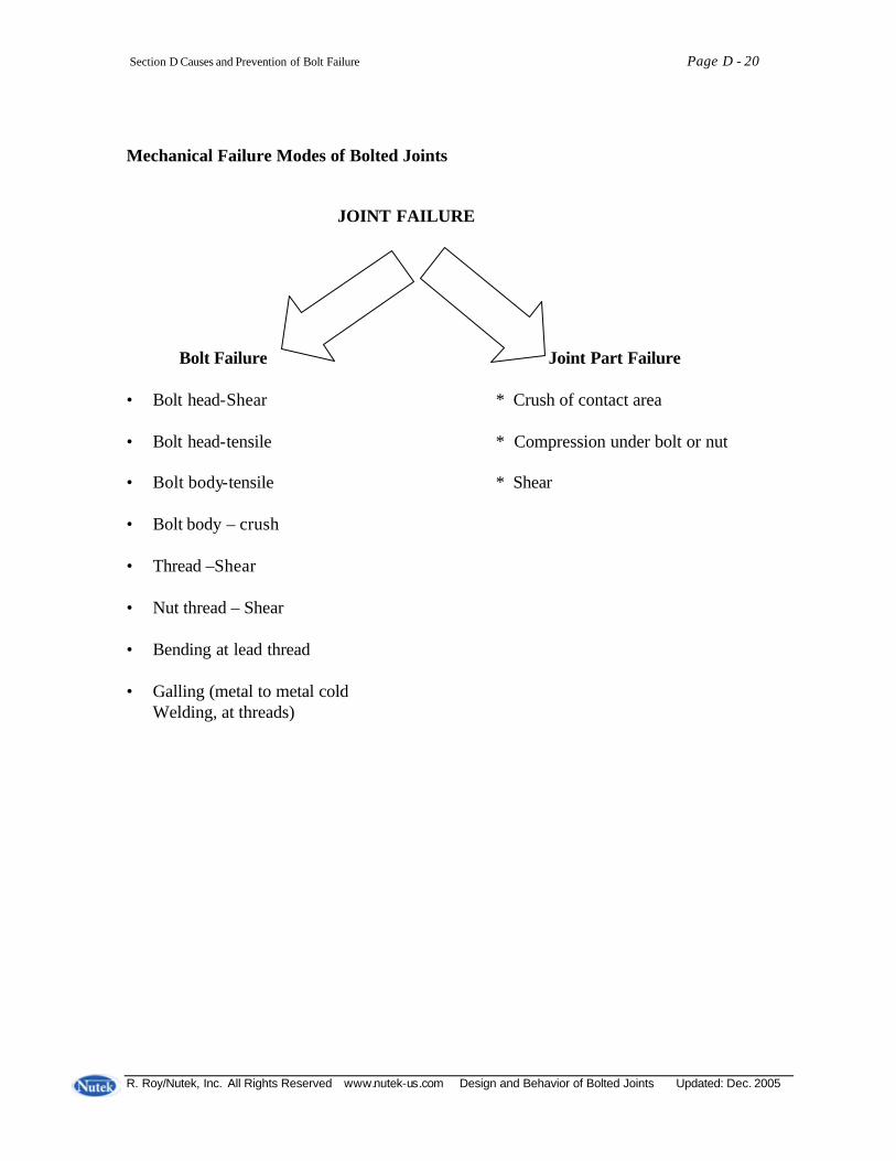
Section D Causes and Prevention of Bolt Failure Page D - 20
R. Roy/Nutek, Inc. All Rights Reserved www.nutek-us.com Design and Behavior of Bolted Joints Updated: Dec. 2005
Mechanical Failure Modes of Bolted Joints
JOINT FAILURE
Bolt Failure Joint Part Failure • Bolt head-Shear * Crush of contact area • Bolt head-tensile * Compression under bolt or nut • Bolt body-tensile * Shear • Bolt body – crush • Thread –Shear • Nut thread – Shear • Bending at lead thread • Galling (metal to metal cold
Welding, at threads)

Section D Causes and Prevention of Bolt Failure Page D - 21
R. Roy/Nutek, Inc. All Rights Reserved www.nutek-us.com Design and Behavior of Bolted Joints Updated: Dec. 2005
Bolt Failure under Excessive Torque Neck failure Due to tension Stretched beyond Yield limit Failed due To tension
Bolt Under Torque
Stripped Thread Shear Failure
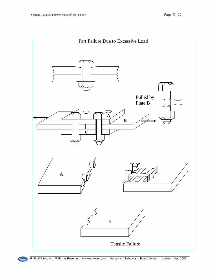
Section D Causes and Prevention of Bolt Failure Page D - 22
R. Roy/Nutek, Inc. All Rights Reserved www.nutek-us.com Design and Behavior of Bolted Joints Updated: Dec. 2005
A B
C
B
A B
Part Failure Due to Excessive Load Pulled by Plate B Tensile Failure
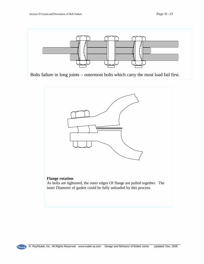
Section D Causes and Prevention of Bolt Failure Page D - 23
R. Roy/Nutek, Inc. All Rights Reserved www.nutek-us.com Design and Behavior of Bolted Joints Updated: Dec. 2005
Bolts failure in long joints – outermost bolts which carry the most load fail first.
Flange rotation As bolts are tightened, the outer edges Of flange are pulled together. The inner Diameter of gasket could be fully unloaded by this process.

Section D Causes and Prevention of Bolt Failure Page D - 24
R. Roy/Nutek, Inc. All Rights Reserved www.nutek-us.com Design and Behavior of Bolted Joints Updated: Dec. 2005
Prevention of Vibration Loosening Common actions
- Keep friction forces above the forces trying to loosen joint. - Mechanically prevent slip between bolt/nut and the joint surfaces. - Reduce the helix angle of the thread to reduce back-off torque component - (w sinθ).
- Provide a “prevailing torque” or locking action of some sort which counters the back-off torque created by the incline plane of the thread.
-
θ
w sinθ
w Cosθ w
Nylon Pellet In bolt Thread Interference Nuts with Nylon locking
Fit thread out-round collar nut hole

Section D Causes and Prevention of Bolt Failure Page D - 25
R. Roy/Nutek, Inc. All Rights Reserved www.nutek-us.com Design and Behavior of Bolted Joints Updated: Dec. 2005
Other devices
- dowel pin - welding - glue/adhesive
JOINTS THAT RESIST TRANSVERSE SLIP
Toothed Shear Washer

Section D Causes and Prevention of Bolt Failure Page D - 26
R. Roy/Nutek, Inc. All Rights Reserved www.nutek-us.com Design and Behavior of Bolted Joints Updated: Dec. 2005
Lock or Spring Washers, Free-Spinning Lock nuts or Bolts, and Lock Bolts. Serrated Head Bolt Spring Head Nut Spring Arm on top of nut Spring Clip Retainer Plate

Section D Causes and Prevention of Bolt Failure Page D - 27
R. Roy/Nutek, Inc. All Rights Reserved www.nutek-us.com Design and Behavior of Bolted Joints Updated: Dec. 2005
Mechanical Properties of Typical Medium/Low Carbon and Case Hardened Steels σu = Tensile Strength (ultimate Stress) σy = Yield Strength (psi) Steel Condition σu σy Steel Condition σu σy 1010 Hot-rolled
Cold-drawn 51,000 56,000
29,000 33,000
4320 Hot-rolled Cold-drawn
87,000 99,000
59,000 65,000
1020
Hot-rolled Cold-drawn
67,000 69,000
45,000 48,000
4340 Hot-rolled, annealed
115,000 95,000
1035
Hot-rolled Cold-drawn
88,000 92,000
55,000 59,000
4620
Hot-rolled Cold-drawn
82,000 98,000
55,000 70,000
1045
Hot-rolled Cold-drawn
99,000 110,00
60,000 69,000
4640 Hot-rolled, annealed
100,0076,000
87,000 57,000
1112
Hot-rolled Cold-drawn
67,000 80,000
40,000 62,500
8620 Hot-rolled Annealed
91,000 76,000
64,000 57,000
2317
Hot-rolled Cold-drawn
85,000 95,000
56,000 75,000
8640 Hot-rolled Annealed
126,000 95,000
89,000 63,000
3140
Hot-rolled- annealed Cold drawn- annealed
96,000 115,000
64,000 98,000
9260 Hot-rolled, annealed
142,000 92,000
1010 – 1020 Steels are used for common fasteners

Section D Causes and Prevention of Bolt Failure Page D - 28
R. Roy/Nutek, Inc. All Rights Reserved www.nutek-us.com Design and Behavior of Bolted Joints Updated: Dec. 2005
Numbering Systems for Carbon and Alloy Steels
The numbering system of the Society of Automotive Engineers (SAE) and American Iron and Steel Institute (AISI) is based on the chemical composition, and provides a simple means of identifying steel. 4 (or 5) digit designation X X X X X Example: Steel 1020 → plain Carbon Steel with .20% carbon
Basic Numerals for SAE and AISI Steels Carbon Steels Plain Carbon Free Cutting Screw Stock
1xxx 10xx 11xx
Molybdenum Steel Carbon-Molybdenum Chr.-Molybdenum Ni.-Molybdenum
4xxx 40xx 43xx 46xx
Nickel Steel 3.5% Ni 5% Ni
2xxx 23xx 25xx
Chromium Steels Low chromium Medium Chromium Corrosion and heat resist.
5xxx 51xx 52xx 51xxx
Nickel Chromium Steel 1.25% Ni 1.75% Ni 3.5% Ni
3xxx 31xx 32xx 33xx
Chromium-Vanadium Steels (1% Cr)
6xxx 61xx
Silicon-Manganese Steels 2% Si
9xxx 92xx
Indicate type of alloy (alloy classification)
Indicate carbon content (2 or 3 digits)

Section D Causes and Prevention of Bolt Failure Page D - 29
R. Roy/Nutek, Inc. All Rights Reserved www.nutek-us.com Design and Behavior of Bolted Joints Updated: Dec. 2005
Load Magnification on Joints (Change in clamping force)
Effect of Prying:
- Magnifies load (exceeds yield point) - Applies bending load
P P P More prying when joint member is flexible. Less prying when joint member is rigid Prying Caused by Offset Loads P FB
P FB >> P
Section D Causes and Prevention of Bolt Failure Page D - 30
R. Roy/Nutek, Inc. All Rights Reserved www.nutek-us.com Design and Behavior of Bolted Joints Updated: Dec. 2005
Fatigue Failure A fastener under repeated cyclic tension loads can unexpectedly and suddenly fail – even though the loads applied are below the yield strength of material. Failure under repeated compression load is rare and is ignored. Necessary conditions for fatigue failure:
1. Cyclic tensile load 2. Stress level above a threshold value (Endurance limit) 3. A susceptible to fatigue material 4. An initial flaw in that material
The process and sequence of fatigue failure: Crack initiation – generally initiated by a flaw.
• tool mark • scratch produced by mishandling of part • improper heat treatment • corrosion • inclusions in material
Crack growth – Small cracks create stress concentrations. Subsequently when the part is subjected to cyclic load, the stress concentration areas yield and tear the material.

Section D Causes and Prevention of Bolt Failure Page D - 31
R. Roy/Nutek, Inc. All Rights Reserved www.nutek-us.com Design and Behavior of Bolted Joints Updated: Dec. 2005
Crack propagation – As the crack grows, the stress level increases, since there is less area to support the load. As stress level increases, the crack grows more rapidly. Final rupture – The part fails at a point when crack has damaged the capability for the part to withstand additional load cycle. The failure occurs rapidly, which appear to be sudden to the user, as there are no visible signs of failure before this point in time.
Types of Fatigue Failure Low-cycle failure – failure occurring in any number from 1 – a few ten thousands cycle (Large load) High-cycle failure – parts failing in cycles over hundreds of thousands or millions cycles (Smaller loads)
Crack Lenth Rupture Propagation Growth Number of Cycles
Crack Initiation
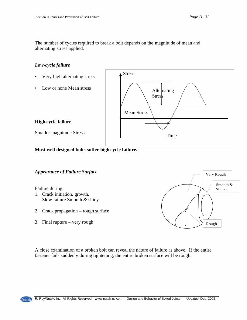
Section D Causes and Prevention of Bolt Failure Page D - 32
R. Roy/Nutek, Inc. All Rights Reserved www.nutek-us.com Design and Behavior of Bolted Joints Updated: Dec. 2005
The number of cycles required to break a bolt depends on the magnitude of mean and alternating stress applied. Low-cycle failure • Very high alternating stress • Low or none Mean stress High-cycle failure Smaller magnitude Stress Most well designed bolts suffer high-cycle failure. Appearance of Failure Surface
Failure during: 1. Crack initiation, growth,
Slow failure Smooth & shiny 2. Crack propagation – rough surface 3. Final rupture – very rough A close examination of a broken bolt can reveal the nature of failure as above. If the entire fastener fails suddenly during tightening, the entire broken surface will be rough.
Very Rough
Smooth & Shiney
Rough
Stress Alternating Stress Mean Stress Time
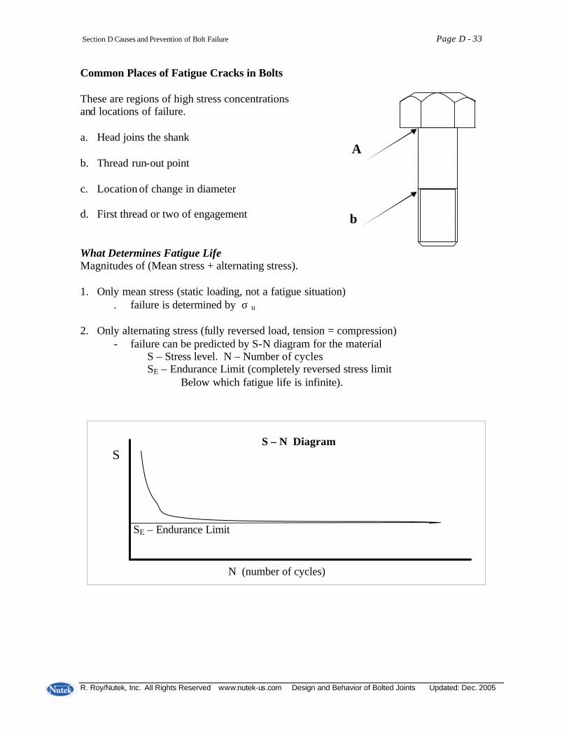
Section D Causes and Prevention of Bolt Failure Page D - 33
R. Roy/Nutek, Inc. All Rights Reserved www.nutek-us.com Design and Behavior of Bolted Joints Updated: Dec. 2005
Common Places of Fatigue Cracks in Bolts These are regions of high stress concentrations and locations of failure. a. Head joins the shank b. Thread run-out point c. Location of change in diameter d. First thread or two of engagement What Determines Fatigue Life Magnitudes of (Mean stress + alternating stress). 1. Only mean stress (static loading, not a fatigue situation)
- failure is determined by σ u
2. Only alternating stress (fully reversed load, tension = compression)
- failure can be predicted by S-N diagram for the material S – Stress level. N – Number of cycles SE – Endurance Limit (completely reversed stress limit Below which fatigue life is infinite).
S – N Diagram S SE – Endurance Limit N (number of cycles)
A
b
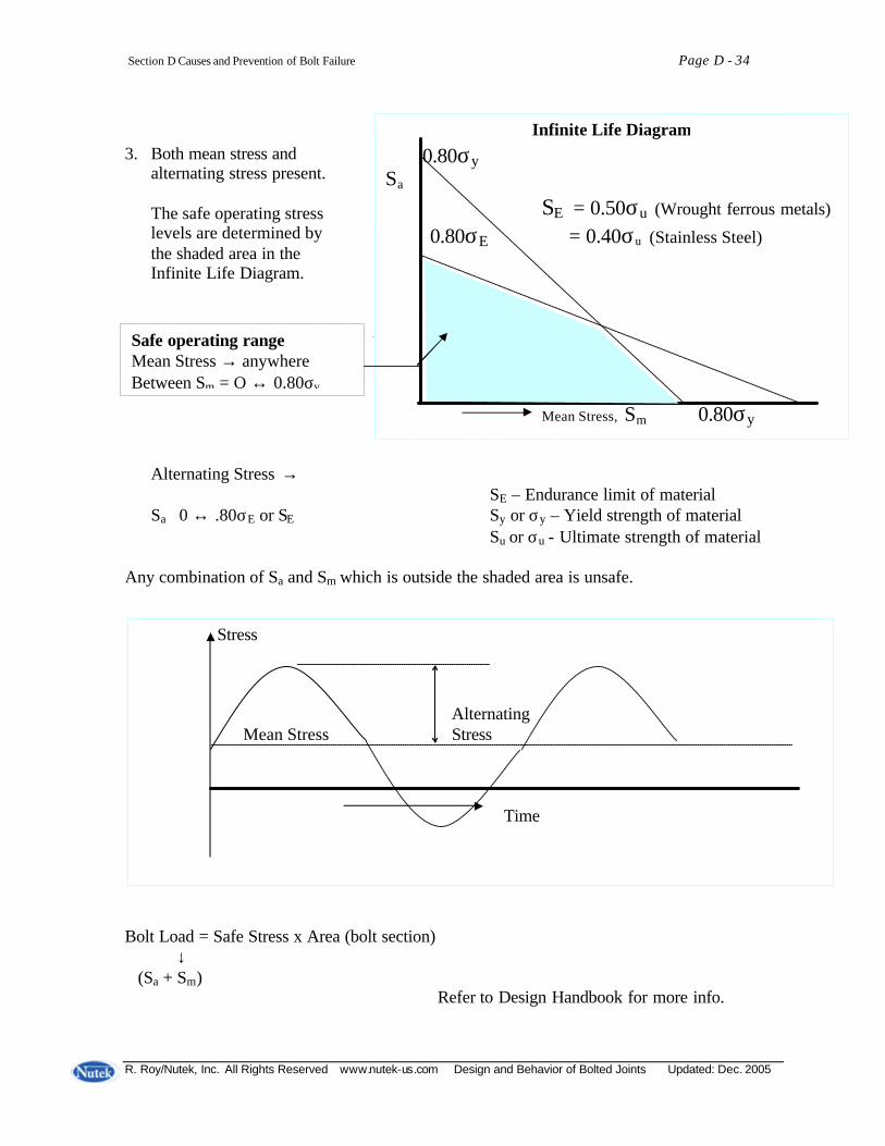
Section D Causes and Prevention of Bolt Failure Page D - 34
R. Roy/Nutek, Inc. All Rights Reserved www.nutek-us.com Design and Behavior of Bolted Joints Updated: Dec. 2005
3. Both mean stress and
alternating stress present. The safe operating stress levels are determined by the shaded area in the Infinite Life Diagram. Alternating Stress → SE – Endurance limit of material Sa 0 ↔ .80σE or SE Sy or σy – Yield strength of material
Su or σu - Ultimate strength of material Any combination of Sa and Sm which is outside the shaded area is unsafe. Bolt Load = Safe Stress x Area (bolt section) ↓ (Sa + Sm)
Refer to Design Handbook for more info.
Stress Alternating Mean Stress Stress Time
Safe operating range Mean Stress → anywhere Between Sm = O ↔ 0.80σy
Infinite Life Diagram
0.80σy
Sa
SE = 0.50σu (Wrought ferrous metals)
0.80σE = 0.40σu (Stainless Steel)
Mean Stress, Sm 0.80σy
0.80σ
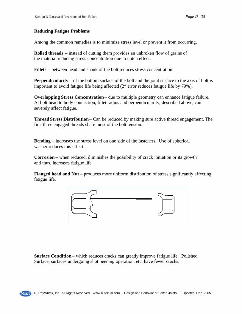
Section D Causes and Prevention of Bolt Failure Page D - 35
R. Roy/Nutek, Inc. All Rights Reserved www.nutek-us.com Design and Behavior of Bolted Joints Updated: Dec. 2005
Reducing Fatigue Problems
Among the common remedies is to minimize stress level or prevent it from occurring. Rolled threads – instead of cutting them provides an unbroken flow of grains of the material reducing stress concentration due to notch effect. Fillets – between head and shank of the bolt reduces stress concentration. Perpendicularity – of the bottom surface of the bolt and the joint surface to the axis of bolt is important to avoid fatigue life being affected (2° error reduces fatigue life by 79%). Overlapping Stress Concentration – due to multiple geometry can enhance fatigue failure. At bolt head to body connection, fillet radius and perpendicularity, described above, can severely affect fatigue. Thread Stress Distribution – Can be reduced by making sure active thread engagement. The first three engaged threads share most of the bolt tension. Bending – increases the stress level on one side of the fasteners. Use of spherical washer reduces this effect. Corrosion – when reduced, diminishes the possibility of crack initiation or its growth and thus, increases fatigue life. Flanged head and Nut – produces more uniform distribution of stress significantly affecting fatigue life. Surface Condition – which reduces cracks can greatly improve fatigue life. Polished Surface, surfaces undergoing shot peening operation, etc. have fewer cracks.
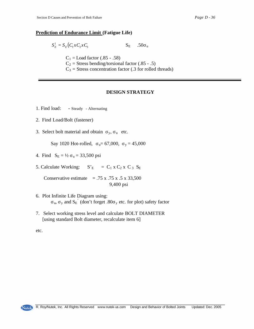
Section D Causes and Prevention of Bolt Failure Page D - 36
R. Roy/Nutek, Inc. All Rights Reserved www.nutek-us.com Design and Behavior of Bolted Joints Updated: Dec. 2005
Prediction of Endurance Limit (Fatigue Life) ( )321
1 xCxCCSS EE = SE ≅ .50σu C1 = Load factor (.85 - .58) C2 = Stress bending/torsional factor (.85 - .5) C3 = Stress concentration factor (.3 for rolled threads)
DESIGN STRATEGY 1. Find load: - Steady - Alternating 2. Find Load/Bolt (fastener) 3. Select bolt material and obtain σy, σu etc. Say 1020 Hot-rolled, σu= 67,000, σy = 45,000 4. Find SE = ½ σu = 33,500 psi 5. Calculate Working: S’E = C1 x C2 x C 3 SE Conservative estimate = .75 x .75 x .5 x 33,500
≅ 9,400 psi
6. Plot Infinite Life Diagram using: σu, σy and SE
’ (don’t forget .80σy etc. for plot) safety factor
7. Select working stress level and calculate BOLT DIAMETER [using standard Bolt diameter, recalculate item 6] etc.
R. Roy/Nutek, Inc. All Rights Reserved www.nutek-us.com Design and Behavior of Bolted Joints Updated: Dec. 2005
APPENDIX Sources of Bolting Specifications AISC American Institute of Steel Construction, Inc. 400 North Michigan Avenue Chicago, Illinois 60611 AISI American Iron and Steel Institute 1000 16th Street N.W. Washington, D.C. 20036 AMS Obtain Aeronautical Material Specifications from: Society of Automotive Engineers 400 Commonwealth Drive Warrendale, Pennsylvania 15096 ASME American Society of Mechanical Engineers United Engineering Center 345 E. 47th Street New York, N.Y. 10017 ANSI American National Standards Institute 1430 Broadway New York, N.Y. 10018 (or from ASME) ASTM American Society for Testing and Materials 1916 Race Street Philadelphia, Pennsylvania 19103 BS British Standards Institution Sales Branch Newton House 101/113 Pentonville Rd. London N1, England

Page Appendix E-2
Nutek, Inc. All Rights Reserved. www.nutek-us.com Design and Behavior of Bolted Joints Version: 0602
The Fastener Quality Act: Insignia Recordals (The Fastener Quality: http://www1.uspto.gov/web/offices/tac/fqa/fqa.htm) The Fastener Quality Act (15 U.S.C. §§ 5401 et seq.) requires that certain fasteners bear an identifying insignia for traceability purposes, and requires the Secretary of Commerce to provide for the recordation of these insignia. The implementing regulations (15 C.F.R. §§280.700 et seq.) direct the Commissioner of Patents and Trademarks to maintain a Fastener Insignia Register. Background The Fastener Quality Act requires that certain fasteners sold in commerce conform to the specifications to which they are represented to be manufactured. Product inspection, testing, and certification are required, as well as record keeping and fastener insignia recordal. The National Institute of Standards and Technology (NIST) have responsibility for all aspects of the law except its enforcement and the mandatory insignia recordal requirement. The Patent and Trademark Office (PTO) has been tasked with establishing and maintaining a Fastener Insignia Register (FIR); the Bureau of Export Administration (BXA) will be the enforcement arm of FQA. All three agencies mentioned are sub-agencies within the purview of the U.S. Department of Commerce. When Will the FQA be in Full Force? On August 14, 1998, an amendment to the Fastener Quality Act was signed into law. (P.L 105-234). This amendment provides, among other things, that regulations issued under the Act will not take effect until after the later of June 1, 1999, or the expiration of a 120 day period after submission of a report by the Secretary of Commerce to various congressional committees. The amendment has been interpreted to provide that the implementation date of the FQA will be the date on which regulations issued under the Act take effect. Who Must Record Their Insignia? Fastener manufacturers and private label distributors, as defined in the Fastener Quality Act. 15 U.S.C. 5402. What Kind of Fasteners Must Bear Insignias and Record these Insignias Under FQA? The FQA insignia recordal requirements in Section 8 apply to a specific sub-set of fasteners, i.e., to those fasteners that are required by the manufacturing standards and specifications to bear a raised or depressed insignia that identifies its maker or distributor. 15 U.S.C. §5407. Certainly there are fasteners in which the standards and specifications do not require that they bear a source- identifying insignia, and there are cases in which it is impracticable for the fastener to bear an insignia. Please note that quality- identifying insignia are not recorded under FQA. If there are any questions regarding whether recordal is required, please contact NIST for verification.
Page Appendix E-3
Nutek, Inc. All Rights Reserved. www.nutek-us.com Design and Behavior of Bolted Joints Version: 0602
Glossary of Fastener and Bolted Joint Terms Angularity The underfaces of the nut and bolt head should be exactly perpendicular to the thread or shank axes. If the angle between the face and the axis is, for example, 86° or 94°, the fastener is said to have an angularity of 4° (sometimes called Perpendicularity). Anode That electrode in a battery or corrosion cell which produces electrons. It is the electrode which is destroyed (corrodes). Brittle A bolt is said to be brittle if it will break when stretched only a small amount past is yield point. (Compare Ductile.) Cathode That electrode in a battery or corrosion cell which attracts electrons. Clamping force The equal and opposite forces which exist at the interface between two joint members. The clamping force is created by tightening the bolts, but is not always equal to the combined tension in the bolts. Hole interference problems, for example, can create a difference between clamping force and bolt loads. Constant life diagram A plot of experimentally derived fatigue –life data; perhaps the most complex and complete of the popular charts used to represent such data. Corrosion cell A natural “battery” formed when two metals having different electrical potentials (an Anode and a Cathode) are connected together in the presence of a liquid (the Electrolyte). Creep The slow, plastic deformation of a body under heavy loads. Time-dependent plasticity. Ductile If a bolt can be stretched well past its yield point before breaking, it is said to be ductile. (See also Brittle.) Eccentric load The external load on a fastener or groups of fasteners is said to be eccentric if the resultant of that load does not pass through the center of the group of fasteners (eccentric shear load) or does not coincide with the bolt axis (eccentric tensile load). Effective length of a bolt The grip length plus some portion of the bolt (often one-half of the thickness of the nuts) which lies within the nut(s) plus some portion (often one-half thickness) of the head. Used in stiffness and stretch calculations. Effective radius of not, or bolt head, or threads Distance between the geometric center of the part and the circle of points through which the resultant contact forces between mating parts passes. Must be determined by integration. Electrode The two metallic bodies in a battery or Corrosion cell which give up electrons (the Anode) or which attract them (the Cathode).
Page Appendix E-4
Nutek, Inc. All Rights Reserved. www.nutek-us.com Design and Behavior of Bolted Joints Version: 0602
Embedment Localized plastic deformation in heavily loaded fasteners allows one part to sink into, or smooth the surface of, a softer or more heavily loaded second part. Nuts embed themselves in joint faces. Bolt threads embed themselves in nut threads, etc. Endurance limit That completely reversing stress limit below which bolt or joint member will have an essentially infinite life under cycle fatigue loads. Note that the mean stress on the bolts here is zero. External load Forces exerted on fastener and/or joint members by such external factors as weight, wind, inertia, vibration, temperature expansion, pressure, etc. Does not equal the Working load in the fastener. Failure of the bolt Failure of a bolted joint to behave as intended by the designer. Failure can be caused or accompanied by broken or lost bolts, but can also mean joint slip or leakage from a gasketed joint even if all bolts still remain whole and in place. Common reasons for joint failure include vibration loosening, poor assembly practices, improper design, unexpected service loads or conditions, etc. Fillet Transition region between bolt head and shank, or between other changes in diameter. (See Bolt, parts of.) Galling An extreme form of adhesive wear, in which large chunks of one part stick to the mating part (during sliding contact). Galvanic protection The coating on a fastener is said to provide galvanic protection if it is more anodic than the fastener and will, therefore, be destroyed instead of the fastener. Zinc plate (galvanizing) provides galvanic protection to steel fasteners, for example. Grip length Combined thickness of all the things clamped together by the bolt and nut, including washers, gaskets and joint members. Hydrogen embrittlement A common and troublesome form of Stress cracking. Several theories have been proposed to explain hydrogen embrittlement, but, at present, the exact mechanism is still unknown. What is known, however, is the fact that if hydrogen is trapped in a bolt by poor electroplating practices, it can encourage stress cracking. Bolts can fail, suddenly and unexpectedly, under normal load. Impact wrench An air- or electric-powered wrench in which multiple blows from tiny hammers are used to produce output torque to tighten fasteners. Inclusions Small pieces of nonmetallic impurities trapped within the base metal or, for example, a bolt. Infinite life diagram A simple plot experimentally derived fatigue life data, showing the conditions required for infinite life.

Page Appendix E-5
Nutek, Inc. All Rights Reserved. www.nutek-us.com Design and Behavior of Bolted Joints Version: 0602
Initial preload The tension created in a single bolt as it is tightened. Will usually be modified by the subsequent assembly operations and/or by in-service loads and conditions. Joint diagrams Mathematical diagrams which illustrate the forces on and deflections of fasteners and joint members. Junker machine A test machine, first proposed by Gerhard Junker, for testing the vibration resistance of fasteners. Lockbolt A fastener which bears a superficial resemblance to a bolt, but which engages a collar (instead of a nut) with annular grooves (instead of threads). The collar is swaged over the grooves on the male fastener to develop preload. Lock nut A nut which provides extra resistance to vibration loosening (beyond that produced by proper Preload), either by providing some form of Prevailing torque, or, in free-spinning lock nuts, by deforming, cramping, and/or biting into mating parts when fully tightened. Material velocity The velocity of sound in a body (e.g., a bolt). A term used in the ultrasonic measurement of bolt stress or strain. Nominal diameter The “catalog diameter” of a fastener. Usually roughly equal to the diameter of the body, or the outer diameter of the threads. Nut factor An experimental constant used to evaluate or describe the ratio between the torque applied to a fastener and the Preload achieved as a result. Pitch The nominal distance between two adjacent thread roots or crests. Preload The tension created in a threaded fastener when the nut is first tightened. Often used interchangeably, but incorrectly, the Working load or bolt force or bolt tension. Prevailing torque Torque required to run a nut down against the joint when some obstruction, such as a plastic insert in the thread or a noncircular thread, or other, has been introduced to help the fastener resist vibration loosening. Prevailing torque, unlike “normal” torque on a nut or bolt, is not proportional to the Preload in the fastener. Proof load The maximum, safe, static, tensile load which can be placed on a fastener without yielding it. Sometimes given as a force (in lb or N) sometimes as a stress (in psi or Mpa). Relaxation The loss of tension, and therefore Clamping force, in a bolt and joint as a result of Embedment, vibration loosening, gasket creep, differential thermal expansion, etc. Residual preload The tension which remains in an unloaded bolted joint after Relaxation.
Page Appendix E-6
Nutek, Inc. All Rights Reserved. www.nutek-us.com Design and Behavior of Bolted Joints Version: 0602
Rolled thread A thread formed by plastically deforming the surface of the blank rather than by cutting operations. Increases fatigue life and thread strength, but is not possible (or perhaps economical) on larger sizes Scatter Data points or calculations are said to be scattered when they are not all the same. A “lot of scatter in preload” means wide variation in the preloads found in individual bolts. Screw Threaded fastener designed to be used in a tapped or untapped (e.g., wood screw) hole, but not with a nut. Self-loosening The process by which a supposedly tightened fastener becomes loose, as a result of vibration, thermal cycles, shock, or anything else which cause transverse slip between joint members and/or male and female threads. Vibration loosening is a common, but special, case of self- loosening. Shank That portion of a bolt which lies under the head. Spring constant The ratio between the force exerted on a spring (or a bolt) and the deflection thereof. Has the dimensions of force per unit change in length (e.g., lb/in.). Also called Stiffness. Standard deviation A statistical term used to quantify the Scatter in a set of data points. If the standard deviation is small, most of the data points are “nearly equal”. A large deviation means less agreement. Strength of bolt An ambiguous term which can mean Ultimate strength or Proof load or Endurance limit or Yield strength. Stress area The effective cross-sectional area of the threaded section of a fastener. Used to compute average stress levels in that section. Based on the mean of pitch and minor diameters. Stress corrosion cracking (SCC) A common form of Stress cracking in which an Electrolyte encourages the growth of a crack in a high stressed bolt. Only a tiny quantity of electrolyte need be present at the tip or face of the crack. Stress cracking A family of failure modes, each of which involves high stress and chemical action. The family includes Hydrogen embrittlement, Stress Corrosion Cracking, stress embrittlement, and hydrogen-assisted stress corrosion. Stress factor A calibration constant used in ultrasonic measurement of bolt stress or strain. It is the ratio between the change in ultrasonic transit time caused by the change in length of the fastener under load, to the total change in transit time (which is also affected by change in the stress level).
Page Appendix E-7
Nutek, Inc. All Rights Reserved. www.nutek-us.com Design and Behavior of Bolted Joints Version: 0602
Stress relaxation The slow decrease in stress level within a part (e.g., a bolt) which is heavily loaded under constant deflection conditions. A “cousin” to creep, which is a slow change in geometry under constant stress conditions. Temperature factor A calibration constant used in ultrasonic measurement of bolt stress or strain. Accounts for the effects of thermal expansion and the temperature- induced change in the velocity of sound. Tension, bolt Tension (tensile stress) created in the bolt by assembly preloads and/or such things as thermal expansion, service loads, etc. Tensioner A hydraulic tool used to tighten a fastener by stretching it rather than by applying a substantial torque to the nut. After tensioner has stretched the bolt or stud, the nut is run down against the joint with a modest torque, ant the tensioner is disengaged from the fastener. The nut holds the stretch produced by the tensioner. Thread form The cross-sectional shape of the threads, defining thread angle, root, and crest profiles, etc. Thread length Length of that portion of the fastener which contains threads cut or rolled to full depth. (See Dimensions of bolt.) Thread run-out That portion of the threads which are not cut or rolled full depth, but which provide the transition between full-depth threads and the body or head. (See Bolts, parts of.) Officially called thread washout or vanish, although the term run-out is more popular. (Run-out is officially reserved for rotational eccentricity, as defined by total indicator readings or the like.) Threaded fastener Studs, bolts, and screws of all orts, with associated nuts. One of the most interesting, complex, useful – and frustrating—components yet devised. Tightness A measure of the mass leak rate from a gasketed joint. Tightness parameter A dimensionless parameter which defines the mass leakage of a gasket as a function of contained pressure and a contained fluid constant. Torque The twisting moment, product of force and wrench length applied to a nut or bolt (for example). Torque monitor A torque tool control system which monitors the amount of torque being developed by the tool during use, but does not control the tool or the torque produced. Torque multiplier A gearbox used to multiply the torque produced by a small hand wrench (usually a Torque wrench). The output of the multiplier drives the nut or bolt with a torque that is higher, and a speed that is lower, than input torque and speed. There is no torque gauge or read-out on the multiplier.

Page Appendix E-8
Nutek, Inc. All Rights Reserved. www.nutek-us.com Design and Behavior of Bolted Joints Version: 0602
Torque wrench A manual wrench which incorporates a gauge or measuring apparatus of some sort to measure and display the amount of torque being delivered to the nut or bolt. All wrenches produce torque. Only a torque wrench tells how much torque. Transducer A device which converts one form of energy into another. An ultrasonic transducer, for example, converts electrical energy into acoustic energy (at ultrasonic frequencies) and vice versa. Turn-of-nut Sometimes used to describe the general rotation of the nut (or bolt head) as the fastener is tightened. More often used to define a particular tightening procedure in which a fastener is first tightened with a preselected torque, and is then tightened further by giving the nut an additional, measured, turn such as “three flange” (180°). Ultimate strength The maximum tensile strength a bolt or material support prior to rupture. Always found in the plastic region of the stress-strain or force-elongation curve, and so is not a design strength. Also called Tensile strength and ultimate tens ile strength. Ultrasonic extensometer An electronic instrument which measures the change in length of a fastener ultrasonically as, or before and after, the fastener is tightened. Work hardening The slight increase in hardness and strength produced when a body is loaded past its yield point. Also called strain hardening. Working load The tension in a bolt in use; tension produced by a combination of Residual preload and a portion (usually) of any External load. The Joint diagram is usually used to predict the approximate working load a fastener will see in service. Yield strength That stress level which will create a permanent deformation of 0.2% or 0.5% or some other small, preselected, amount in a body. Approximately equal to the elastic and proportional limits of the material; a little higher than the proof strength of a bolt. (See Proof load.)
Page Appendix E-9
Nutek, Inc. All Rights Reserved. www.nutek-us.com Design and Behavior of Bolted Joints Version: 0602
References 1. Bickford, John H., An Introduction to the Design and
Behavior of Bolted Joints, Marcel Dekker, Inc. 270 Madison Ave., New York, NY 10016.
2. Bickford, John H., Nassar, Sayed, Handbook of Bolts and Bolted Joints, Editors , New York: Dekker, 1998
3. Little, Robert E., Bolted Joints: How Much Give?, University of Michigan, Dearborn, November 9, 1967
5 Willet, Fred, The Case of Derailed Disk Drives, Mechanical Engineering, January 1988.
6 Krouse, John K., Fighting Corrosion in Fasteners, Machine Design, February 1981.
7 Gomes, Kenneth J., Fastening Plastics – Part 1, Assembly Engineering, August 1982.
8 Cornford, A. S., Bolt preload – How can you be sure it’s right?, Machine Design, Vol. 47, no. 5, pp. 78-82, March 6, 1975.
9 ASME PCC-1, Guidelines for Pressure Boundary Bolted Flange Joint Assembly, An American National Std (ANSI), Nov. 2000
10 Bickford, John H., Editor Gaskets and Gasketed Joints, New York: Dekker, 1998
11 Salser S. Floyd, How to Keep Hydrogen Embrittled Fasteners Out of Assembled Products,
Assembly Engineering, September 1972. 12 M. Derenne, L. Marchand and J. R. Payne, Elevated Temperature Characterization of
Flexible Graphite Sheet Materials for Bolted Flanged Joints, WRC Bulletin 419, February 1997
13 M. Derenne, J.R. Payne, L. Marchand and A. Bazergui, Development of Test Procedures for Fire Resistance Qualification of Gaskets, WRC Bulletin 377, December 1992

Page Appendix E-10
Nutek, Inc. All Rights Reserved. www.nutek-us.com Design and Behavior of Bolted Joints Version: 0602
Fastener Material Property Comparison (Typical inch and metric fasteners)
Tensile Strength Yield Strength Inch Grade
Marks on Head Material
N/mm2 psi N/mm2 psi 2 none Steel 510 74,000 393 57,000 5 3 Steel 827 120,000 634 92,000 8 6 Alloy Steel 1030 150,000 896 130,000 SHCS none Alloy Steel 1240 180,000 965 140,000 18-8 none 302 Stainless 690 100,000 448 65,000 316 none 316 Stainless 690 100,000 448 65,000
Tensile Strength Yield Strength Metric Class
Marks on Head Material
N/mm2 psi N/mm2 psi 8.8 8.8 Steel 800 116,000 640 93,000 10.9 10.9 Steel 1040 151,000 940 136,000 12.9 12.9 Alloy Steel 1220 177,000 1100 160,000 A2-70 A2-70 302 Stainless 700 102,000 450 65,000 A4-80 A4-80 316 Stainless 800 116,000 600 87,000

Page Appendix E-11
Nutek, Inc. All Rights Reserved. www.nutek-us.com Design and Behavior of Bolted Joints Version: 0602
ASTM, SAE AND ISO GRADE MARKINGS AND MECHANICAL PROPERTIES FOR STEEL FASTENERS

Page Appendix E-12
Nutek, Inc. All Rights Reserved. www.nutek-us.com Design and Behavior of Bolted Joints Version: 0602

Page Appendix E-13
Nutek, Inc. All Rights Reserved. www.nutek-us.com Design and Behavior of Bolted Joints Version: 0602
Notes: (Blank Page)

Page Appendix E-14
Nutek, Inc. All Rights Reserved. www.nutek-us.com Design and Behavior of Bolted Joints Version: 0602
Program Evaluations
Program Title_____________________________________ ____________________________________________ Program completion date Instructor Ranjit K. Roy & …. Training Location/host.____________________________________ We appreciate your comments and suggestions. Please take a moment to let us know how we can improve and serve you better. (Please use the following numbers for evaluation purposes). [6] Excellent [5] Very Good [4] Satisfactory [3] Poor [2] Unsatisfactory [1] Needs Improvement 1. Overall Reaction to Program: 6 5 4 3 2 1 (Circle one number) Comments:______________________________________________________________________________________ _______________________________________________________________________________________________ 2. Reaction to Instructor: 6 5 4 3 2 1 (Circle one number) Comments:______________________________________________________________________________________ _______________________________________________________________________________________________ 3. What should be added and/or deleted to improve this program? (Please be specific) _______________________________________________________________________________________________ 4. What portions of this program do you feel will be most helpful at your work? How? _______________________________________________________________________________________________ ___________________________________________________________________________________________ 5. Do you feel the training provided you enough understanding of the technique for you to be able to start applying it to your own projects if opportunities were available? [ ] Yes [ ] No [ ] May be 6. Would you consider/recommend us for training at your facility? [ ] yes [ ] No [ ] May be Who should we contact for training at your facility __________________________ Ph: ___________________ 7. Would you recommend that others attend this seminar? [ ]YES [ ]NO 8. Portion of class sessions you attended [ ] 100% [ ] Over 90% [ ] over 75% [ ] Over 50% 9. Percent of class problems and assignment you completed and/or took active part: [ ] 100% [ ] Over 80% [ ] 50% (Optional) Your Name_______________________________ Your Ph#/ & E-mail:__________________________________ THANK YOU for taking the time to complete this evaluation.