1 chapters 2 and 3 presentation based on: "what's a microcontroller ?" by andy...
TRANSCRIPT

1
Chapters 2 And 3Chapters 2 And 3
Presentation based on:
"What's a Microcontroller ?"By Andy LindsayParallax, Inc
Presentation developed by:Presentation developed by:
Martin A. HebelMartin A. HebelSouthern Illinois University CarbondaleSouthern Illinois University CarbondaleCollege of Applied Sciences and ArtsCollege of Applied Sciences and ArtsElectronic Systems TechnologiesElectronic Systems Technologies9/02/03

2
Use and CopyrightUse and Copyright
This presentation supplements "What's a Microcontroller" by Andy Lindsay. (Link to text)
This presentation is not a replacement for the text.
Important concepts of the text are highlighted. In some cases, additional material has been
added to augment the text. Denoted by titles colored goldgold.
Full program listings are generally not provided in the presentation.
Distribution:This presentation may be freely distributed without
modifications. Modifications are permitted by schools and organizations for internal use only. Credits, use and copyright slides must remain.

3
COPYRIGHTS AND TRADEMARKSThis documentation is Copyright 2003 by Parallax, Inc. By downloading or
obtaining a printed copy of this documentation or software you agree that it is to be used exclusively with Parallax products. Any other uses are not permitted and may represent a violation of Parallax copyrights, legally punishable according to Federal copyright or intellectual property laws. Any duplication of this documentation for commercial uses is expressly prohibited by Parallax, Inc. Check with Parallax for approval prior to duplicating any of our documentation in part or whole for any use.
BASIC Stamp is a registered trademark of Parallax, Inc. If you decide to use the name BASIC Stamp on your web page or in printed material, you must state that "BASIC Stamp is a registered trademark of Parallax, Inc." Other brand and product names are trademarks or registered trademarks of their respective holders.
DISCLAIMER OF LIABILITYParallax, Inc. and Southern Illinois University are not responsible for special,
incidental, or consequential damages resulting from any breach of warranty, or under any legal theory, including lost profits, downtime, goodwill, damage to or replacement of equipment or property, or any costs of recovering, reprogramming, or reproducing any data stored in or used with Parallax products. Parallax is also not responsible for any personal damage, including that to life and health, resulting from use of any of our products. You take full responsibility for your BASIC Stamp application, no matter how life threatening it may be.

4
Voltage and CurrentVoltage and Current
Voltage and current can be compared to water pressure and flow. When the valve is opened, what will happen? What determines how fast the water will flow?

5
Of course water will flow from the fuller tank because it has greater pressure than the empty tank.
The flow rate is dependent on:The difference in pressure between the
two tanks.The amount of restriction to flow in the
pipe and valve.
The water that flows from your facet is dependent on the height of your town's water tank, the size of the pipes, and how far you open the faucet.

6
In a battery, there is surplus of electrons on one side, and a deficiency of electrons on the other side (holes).
When a circuit is completed, such as putting an LED in it, a flow exists from one side to the other. This is called Current.

7
Current can be viewed in one of 2 ways:Electron Flow: Electrons flow from the
negative side(-) to the positive side.OR
Hole Flow or Conventional Flow: Holes, or the absence of electrons, move from positive to negative as the electrons move.
++++-- -- -- ++---- -- ++ --++-- ++ -- ++--++ -- ++
Electrons (-)Electrons (-)
Holes (+)Holes (+)An atom with an An atom with an excess of electrons excess of electrons has a – charge. One has a – charge. One with a deficiency of with a deficiency of electrons has a + electrons has a + charge.charge.

8
Which version of flow is used doesn't matter. How much flows does. Just as with the water tanks:
The greater the pressure, or the difference in potential (Voltage), the greater the amount of current that can flow in a unit time (Amperes).
The greater the restriction to flow (Ohms), the lower the amount current that can flow.

9
Ohm's LawOhm's Law
Ohms Law states: The amount of current (I) that will flow is proportional to the voltage applied (V), and inversely proportional to the resistance (R) of the circuit.
I = V/R
As Resistance increases, current decreases.

10
The ResistorThe Resistor
The resistor is a device used to limit the amount of current in a circuit. Because it is so small, color bands are used to identify the value.
1st Band: 1st Digit2nd Band: 2nd Digit3rd Band: Multiplier4th Band (if present): Tolerance.
SchematicSymbol
PartDrawing

11
For the resistor shown:Yellow = 4, 1st DigitViolet = 7, 2nd DigitBrown = 1, add 1 zero.470 Ohm or 470
Tolerance is how far off itcould be from the labeledvalue:Gold: 5%Silver: 10%none: 20%

12
What is the resistance of a resistor colored Brown-Black-Orange? (Click slide for answer)
Answer: Brown = 1, Black = 0, Orange = 31, 0 , + 3 zeros = 10,000 ohms or 10K Ohm

13
Breadboard AreaBreadboard Area
A Breadboard is an electrical testing area for prototyping by quickly connecting components.
The rows are electrically connected to make connectionsbetween devices.
Headers are providedon 2 sides for:• I/O connections to the BASIC
Stamp (P0-P15)• Vdd: + Voltage• Vss: - Voltage• Vin: Supply Voltage
from battery or wall transformer
Use of Vin should be used only as directed as it can damage the BASIC Stamp or components.

14
Activity #1 Building and Testing the Light Activity #1 Building and Testing the Light CircuitCircuit
Construct the circuit per your text.As the current path from Vdd(+) to Vss(-)
is completed, the LED will light.
What happens if the LED is reversed?What happens if a 1K ohm resistor is
used?

15
What happens when both sides are connected to the same supply? With no difference in potential (electrical pressure), no current will flow, and the LED will not light.

16
Activity #2: On/Off Control With the BASIC Activity #2: On/Off Control With the BASIC StampStamp
With the BASIC Stamp the Input/Output pins (P0-P15) are controlled to supply either the Vdd (+) or Vss (-) potential. This will control whether a device has a path for current to flow or not.

17
Connect the circuit per your text.

18
Enter the code to control and run per the text:

19
The LED should be flashing on and off once per second.
Key Commands:• HIGH 14: Places I/O pin P14 High. This
correlates to 5V or Vdd (digital 1). Current flows between P14 and Vss energizing the LED.
• PAUSE 500: BASIC Stamp pauses operation for the specified time in milliseconds. 500 milliseconds = 0.5 seconds
• LOW 14: Places I/O pin P14 Low. This correlates to 0V or Vss (digital 0). Current does not flow between P14 and Vss, LED is not energized.
• DO and LOOP: Creates a looping structure for repetition.

20
Activity #1: Testing a PushButton/LED Activity #1: Testing a PushButton/LED CircuitCircuitThe pushbuttons supplied with the kits are
normally-open, momentary contact. That is, the switch does not make contact until the button is pressed. Once released, it returns to the open position.
Open State: The pins on either side are electrically the same point. With the button released, there is no path for electrons between pins 1,4 and 2,3.

21
Closed State: With the button pressed, a conductive material bridges the gap allowing electrons, and thus current, to flow.

22
Pushbutton Test CircuitPushbutton Test Circuit
This circuit demonstrates how the push-buttons switch allows current to flow when closed.
Not pressed - Open: No current flow, LED is not-lit.
Pressed – Open: Current flows lighting the LED.
23
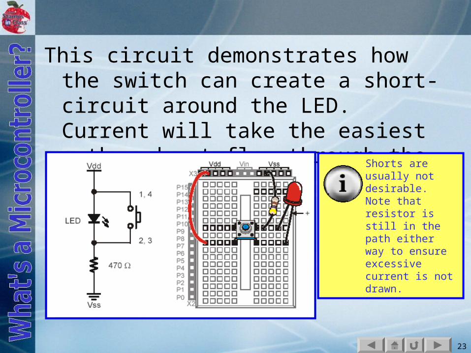
This circuit demonstrates how the switch can create a short-circuit around the LED. Current will take the easiest path and not flow through the LED.
Shorts are usually not desirable. Note that resistor is still in the path either way to ensure excessive current is not drawn.

24
Activity #2: Reading a PushbuttonActivity #2: Reading a Pushbutton
Construct the circuit. Pay attention to the values/colors of the resistors.

25
Enter and test the code by occasionally pressing the pushbutton and monitoring the state in the DEBUG Window.

26
DEBUG ? IN3 displays the value of I/O P3 in the DEBUG Window. Which state relates to 1? Pressed or not pressed?

27
When the switch is pressed, Vdd (+5V) is sensed at the input of P3.
When the switch is released, Vss (0V) is sensed at the input of P3.
The 10K resistor prevents a short circuit from Vdd to Vss

28
In this configuration, the 10K is said to be a Pull-Down resistor since it is pulling the input down to ground or Vss when the button is not active (not pressed).
The switch is said to be Active-High since activating it (pressing it) will cause the input of P3 to be High.

29
This configuration shows a Pull-Up resistor to Vdd, with an Active-Low button.
When the same code is ran with this configuration, when will IN3 be a value of 1?

30
A BASIC Stamp input must always be pulled high or low. If not connected to either, it is said to be floating and produce erratic readings as voltages at the pin fluctuate around 1.4V. <1.4V = Low >1.4V = High
The majority of switches on devices are configured for Active-Low. This is due to input current-draw considerations of most semi-conductor devices.