1 cscd 433 network programming fall 2013 lecture 4 physical layer line coding continued
TRANSCRIPT

1
CSCD 433Network ProgrammingFall 2013
Lecture 4Physical Layer Line CodingContinued

Topics
• Analog Transmission of Digital Data
• Digital Transmission of Analog Data
• Multiplexing
2
3
Analog Transmission of Digital Data Traditional analog transmission has been
the Telephone service POTS – Plain Old Telephone Service Have an existing system of wired
communication Sending digital data over the telephone
service – How do we do it? Use a modem !!! Modems use carrier waves to send
information Known as modulation ….
4
Modulation
Modulation is modification of a carrier wave’s fundamental characteristics in order to encode information
There are three basic ways to modulate a carrier wave:
Amplitude Modulation Frequency Modulation Phase Modulation
5
Amplitude ModulationAmplitude Modulation (AM)
Amplitude Shift Keying (ASK), means changing height of wave to encode data
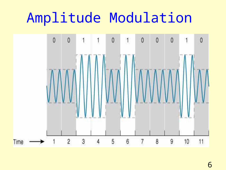
AM dial on radio uses amplitude modulation to encode analog information.•Shows a simple case of amplitude modulation in which one bit is encoded for each carrier wave change.
A high amplitude means a bit value of 1 Zero amplitude means a bit value of 0
6
Amplitude Modulation

7
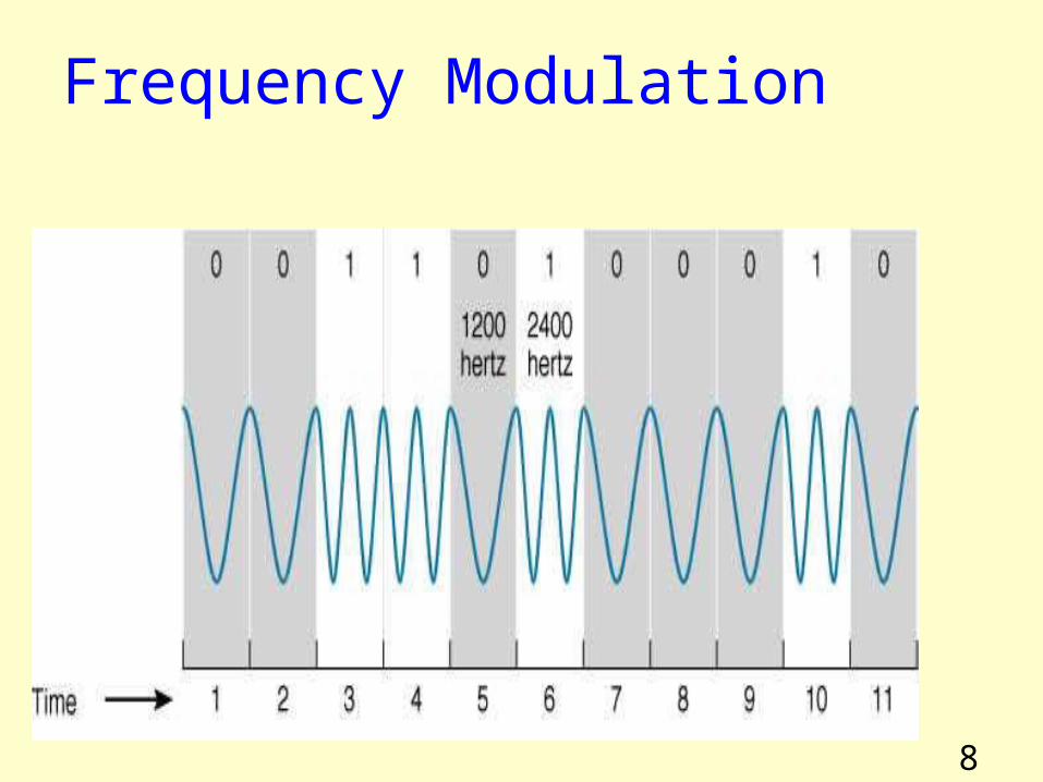
Frequency ModulationFrequency Modulation (FM)Frequency Shift Keying (FSK), means changing frequency of carrier wave to encode dataFM dial on the radio uses frequency modulation to encode analog information.•Next slide simple case of frequency modulation in which one bit is encoded for each carrier wave change.
Changing the carrier wave to a higher frequency encodes a bit value of 1 No change in the carrier wave frequency means a bit value of 0
8
Frequency Modulation
9
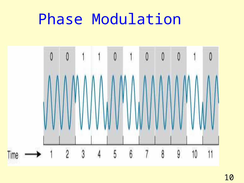
Phase ModulationPhase refers to point in each wave cycle at which the wave begins
Phase Modulation (PM)Phase Shift Keying (PSK) means changing phase of the carrier wave to encode data•Next slide shows a simple case of phase modulation in which one bit is encoded for each carrier wave change
Changing the carrier wave’s phase by
180o corresponds to a bit value of 1 No change in the carrier wave’s phase means a bit value of 0
10
Phase Modulation
11
Sending Multiple Bits Simultaneously Each modification of the carrier wave to encode information is called a symbol.By using a more complicated information coding system, possible to encode more than 1 bit/symbol•Next slide gives an example of amplitude modulation using 4 amplitude levels, corresponding to 2 bits/symbolIncreasing possible number of symbols from 4 to 8 corresponds with encoding 3 bits/symbol, 16 levels to 4 bits, and so on Likewise, multiple bits per symbol might be encoded using phase modulation, say using phase shifts of 0o, 90o, 180o, and 270o

12
Two-bit Amplitude Modulation
13
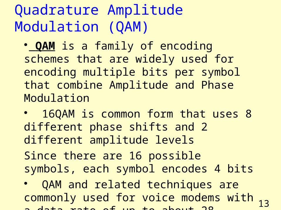
Quadrature Amplitude Modulation (QAM)
QAM is a family of encoding schemes that are widely used for encoding multiple bits per symbol that combine Amplitude and Phase Modulation 16QAM is common form that uses 8 different phase shifts and 2 different amplitude levelsSince there are 16 possible symbols, each symbol encodes 4 bits QAM and related techniques are commonly used for voice modems with a data rate of up to about 28 kilobits/second
14
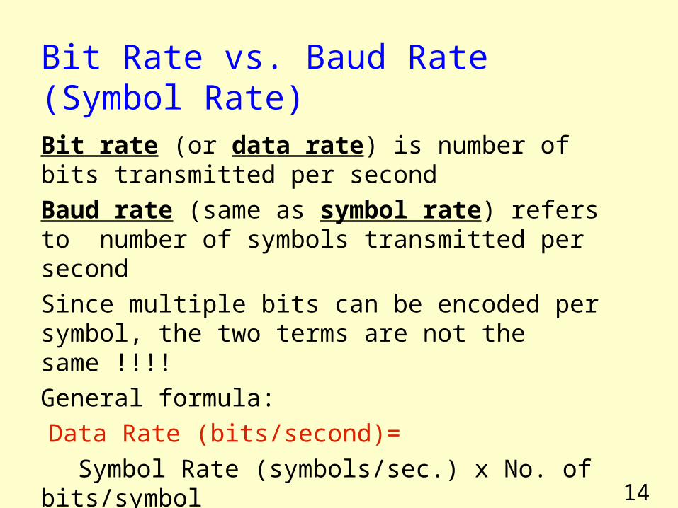
Bit Rate vs. Baud Rate (Symbol Rate)Bit rate (or data rate) is number of bits transmitted per secondBaud rate (same as symbol rate) refers to number of symbols transmitted per secondSince multiple bits can be encoded per symbol, the two terms are not the same !!!!General formula:Data Rate (bits/second)= Symbol Rate (symbols/sec.) x No. of bits/symbol
15
Digital Transmission of Analog Data

16
Techniques for Quantifying Analog Signals
Pulse-code modulation (PCM) is a method used to digitally represent sampled analog signals
It is standard form of digital audio in computers, Compact Discs, telephony and other digital audio applications
In PCM stream, amplitude of analog signal is sampled regularly at uniform intervals, and each sample is quantized to nearest value within a range of digital steps
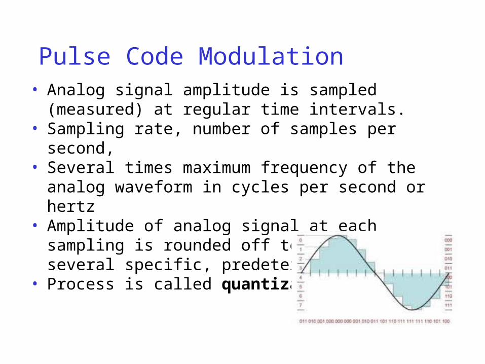
Pulse Code Modulation• Analog signal amplitude is sampled (measured) at
regular time intervals.• Sampling rate, number of samples per second,• Several times maximum frequency of the analog
waveform in cycles per second or hertz• Amplitude of analog signal at each sampling is
rounded off to nearest of several specific, predetermined levels
• Process is called quantization
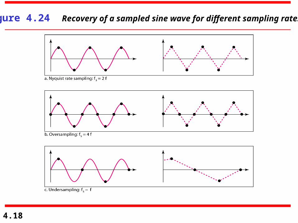
4.18
Figure 4.24 Recovery of a sampled sine wave for different sampling rates

19
Multiplexing
20
MultiplexingMultiplexing
Combining several signals onto one line.Demultiplexing
Taking a multiplexed signal and recovering its original components
Frequency division multiplexing (FDM): Use different
frequency ranges for different signalsWave division multiplexing (WDM): Same as FDM, but
with optical signals Time division multiplexing (TDM): Each signal is
allocated to a periodic time slot CDM is a mathematical approach used in cell phone
and wireless , CDM= Code division multiplexing
21
Frequency Division Multiplexing (FDM)
FDM works by making a number of smaller channels from a larger frequency band
FDM is sometimes referred to as dividing the circuit “horizontally”
In order to prevent interference between channels, unused frequency bands called guardbands are used to separate the channels
Because of guardbands, there is some wasted capacity on an FDM circuit

22
Frequency Division Multiplexing
23
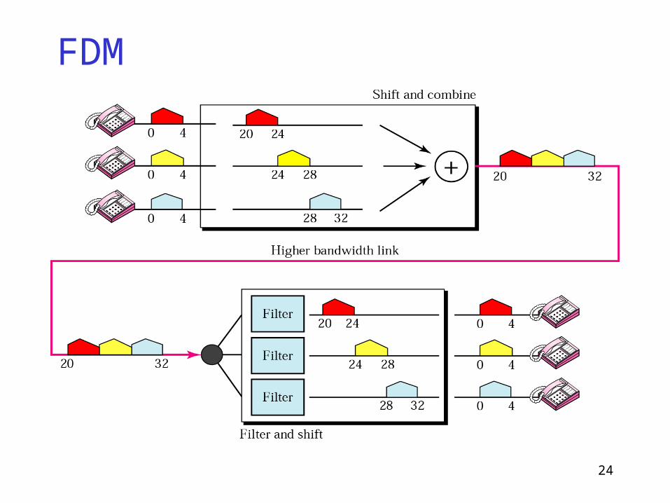
Frequency Division MultiplexingSuppose that we have three phone signals that we want to combine onto one line with higher bandwidth.
Allocate 4 KHz of bandwidth to each signal, which includes a “guard band” of unused frequency range to ensure signals don’t overlap.
Each signal originally uses the range 0.3 – 3.3 KHz.
Transform each signal to a different frequency range:
Signal 1: 20 – 24 KHz channel• Use 20.5 KHz to 23.5 KHz, with 0.5 KHz of guard
band on each end.
Signal 2: 24 – 28 KHz
Signal 3: 28 – 32 KHz
At receiver, filters are used to isolate each channel, and then the frequency is transformed back to its original range.
24
FDM
25
FDM applicationsHigh capacity phone lines
AM radio: 530 KHz to 1700 KHz, 10 KHz bandwidth per station
FM radio: 88 MHz to 108 MHz, 200 KHz bandwidth per station
TV broadcasts: 6 MHz bandwidth per TV channel
First generation cell phones: each user gets two 30 KHz channels (sending, receiving).
26
Wave Division MultiplexingEssentially the same as FDM, except the signals are optical and prisms are used to combine/split signals instead of electrical components.
Used to combine signals of different frequencies (i.e. colours) onto one fibre-optic cable.
27
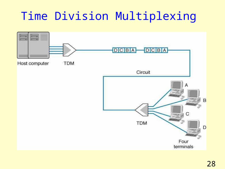
Time Division Multiplexing (TDM)
TDM allows multiple channels to be used by allowing channels to send data by taking turnsTDM is sometimes referred to as dividing circuit “vertically” •Next slide shows an example of 4 terminals sharing a circuit, with each terminal sending one character at a timeWith TDM, time on circuit is shared equally with each channel getting a specified time slot, whether or not it has any data to sendTDM is more efficient than FDM, since TDM doesn’t use guardbands, so the entire capacity can be divided up between the data channels.
28
Time Division Multiplexing
29
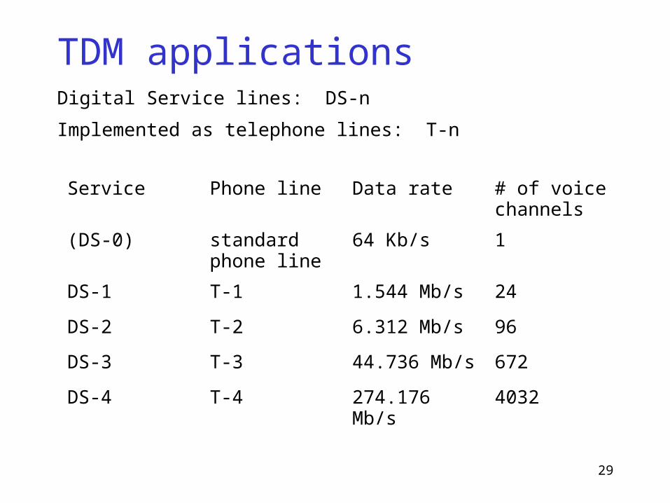
TDM applicationsDigital Service lines: DS-n
Implemented as telephone lines: T-n
Service Phone line Data rate # of voice channels
(DS-0) standard phone line
64 Kb/s 1
DS-1 T-1 1.544 Mb/s 24
DS-2 T-2 6.312 Mb/s 96
DS-3 T-3 44.736 Mb/s 672
DS-4 T-4 274.176 Mb/s 4032

30
Code Division Multiplexing (CDM)
CDM used in parts of cellular telephone system and for some satellite communication
CDM relies on an interesting mathematical ideavalues from orthogonal vector spaces can be combined and separated without interference
Each sender is assigned a unique binary code Ci
that is known as a chip sequencechip sequences are selected to be orthogonal vectors
• Means dot product of any two chip sequences is zero
31
Code Division Multiplexing (CDM)
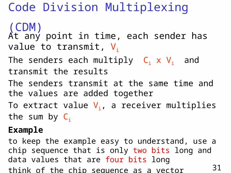
At any point in time, each sender has value to transmit, Vi
The senders each multiply Ci x Vi and transmit the resultsThe senders transmit at the same time and the values are added togetherTo extract value Vi, a receiver multiplies the sum by Ci
Exampleto keep the example easy to understand, use a chip sequence that is only two bits long and data values that are four bits longthink of the chip sequence as a vector
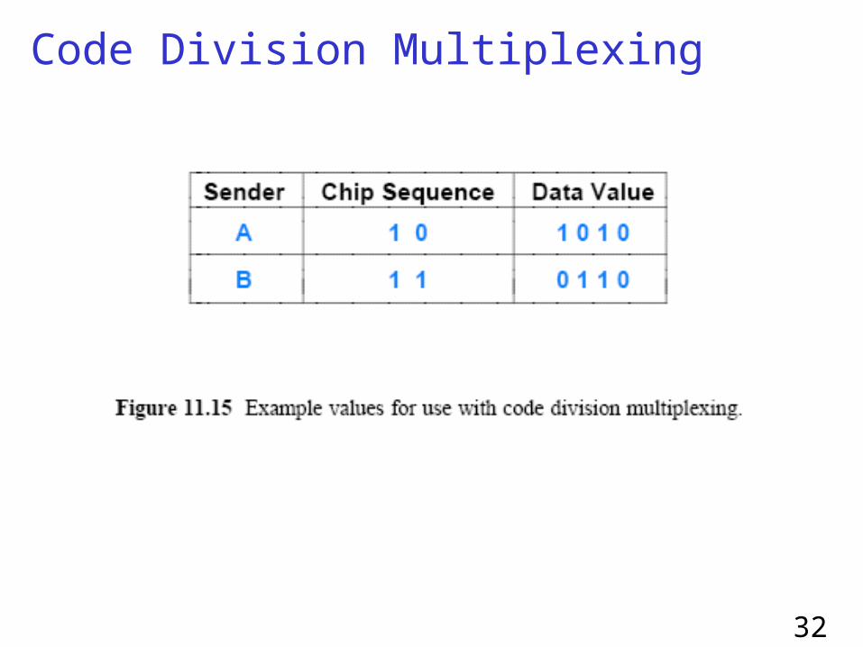
Next slide lists the values
32
Code Division Multiplexing

33
Code Division Multiplexing
The first step consists of converting the binary values into vectors that use -1 to represent 0:
If we think of the resulting values as a combined signal to be transmitted at the same timethe resulting signal will be the sum of the two signals
34
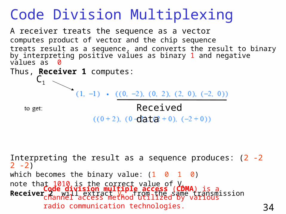
Code Division Multiplexing A receiver treats the sequence as a vectorcomputes product of vector and the chip sequencetreats result as a sequence, and converts the result to binary by interpreting positive values as binary 1 and negative values as 0Thus, Receiver 1 computes:
Interpreting the result as a sequence produces: (2 -2 2 -2)which becomes the binary value: (1 0 1 0)note that 1010 is the correct value of V1
Receiver 2 will extract V2 from the same transmission
C1
Received data
Code division multiple access (CDMA) is a channel access method utilized by various radio communication technologies.
Summary
• Many types of encoding for sending data • Multiplexing allows efficient use of shared
physical media

36
Finish lab this Thursday