cscd 433 network programming -...
TRANSCRIPT

1
CSCD 433Network ProgrammingFall 2016
Lecture 5Physical Layer Continued

Topics
• Definitions• Analog Transmission of Digital Data• Digital Transmission of Analog Data• Multiplexing
2

Different Types of Channels
Intended use of communication channel dictates whether Analog, Digital, Modulated or Unmodulated transmission is needed
– Radio and Cellular communications require modulating signal to fit within specific frequency ranges
– Use of telephone lines for digital data transmission requires different type of modulation to transmit digital over traditionally analog lines
Look at analog signals over digital and digital signals over analog

Definitions
First, need to define terms Carrier Wave Modulation Baseband and Bandpass Channels

5
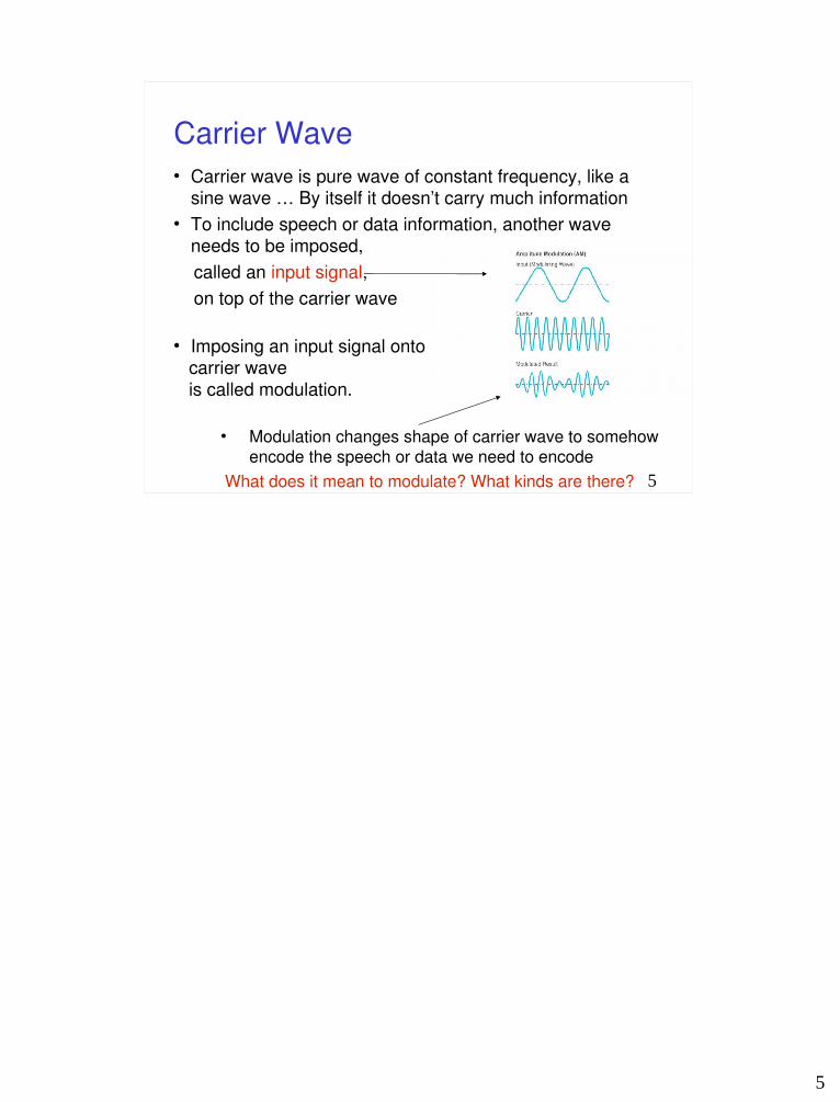
Carrier Wave Carrier wave is pure wave of constant frequency, like a
sine wave … By itself it doesn’t carry much information To include speech or data information, another wave
needs to be imposed, called an input signal, on top of the carrier wave
Imposing an input signal onto carrier wave is called modulation.
Modulation changes shape of carrier wave to somehow
encode the speech or data we need to encode What does it mean to modulate? What kinds are there?
6
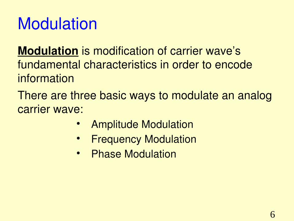
ModulationModulation is modification of carrier wave’s fundamental characteristics in order to encode informationThere are three basic ways to modulate an analog carrier wave:
Amplitude Modulation Frequency Modulation Phase Modulation

Baseband Channels
Baseband transmission is transmission of encoded signal using its own baseband frequencies; i.e. without any shift to higher frequency ranges, Without a shift in range of signal frequencies Signal frequencies are within band of frequencies
from near 0 hertz up to a higher cut-off frequency or maximum bandwidth
Examples: Serial cables and local area networks utilize baseband transmission

Passband Channel A passband channel has range of frequencies or wavelengths that can pass through a
filter In passband transmission, modulation methods are
used so that only a limited frequency range is used Typically, range does not include 0 or low frequencies
Example: Utilizedin wireless communicationand in radio transmission

9
Analog Transmission of Digital Data Traditional analog transmission has been
Telephone service POTS – Plain Old Telephone Service Have an existing system of wired
communication Sending digital data over telephone service –
How do we do it? Use a modem !!! Modems use carrier waves to send
information Known as modulation ….
10
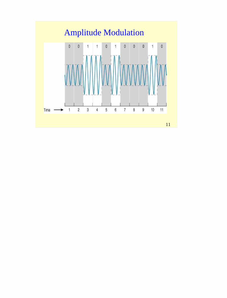
Amplitude ModulationAmplitude Modulation (AM)
Amplitude Shift Keying (ASK), means changing height of wave to encode data
AM dial on radio uses amplitude modulation to encode analog information Next Slide shows simple case of amplitude modulation in which one bit is encoded for each carrier wave change.
A high amplitude means a bit value of 1 Zero amplitude means a bit value of 0
11
Amplitude Modulation
12
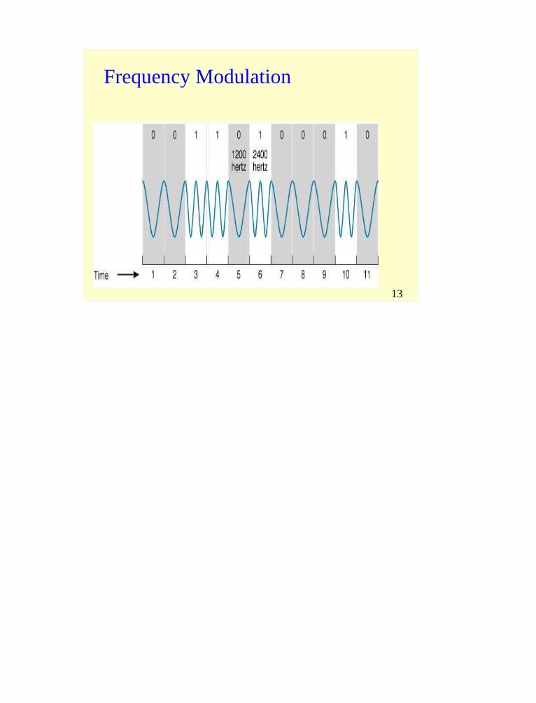
Frequency ModulationFrequency Modulation (FM) Frequency Shift Keying (FSK), change frequency of carrier wave to encode data
– FM radio uses frequency modulation to encode analog information
• Next slide shows frequency modulation in which one bit is encoded for each carrier wave change
Changing carrier wave to a higher frequency encodes a bit value of 1 No change in carrier wave frequency means a bit value of 0

13
Frequency Modulation

14
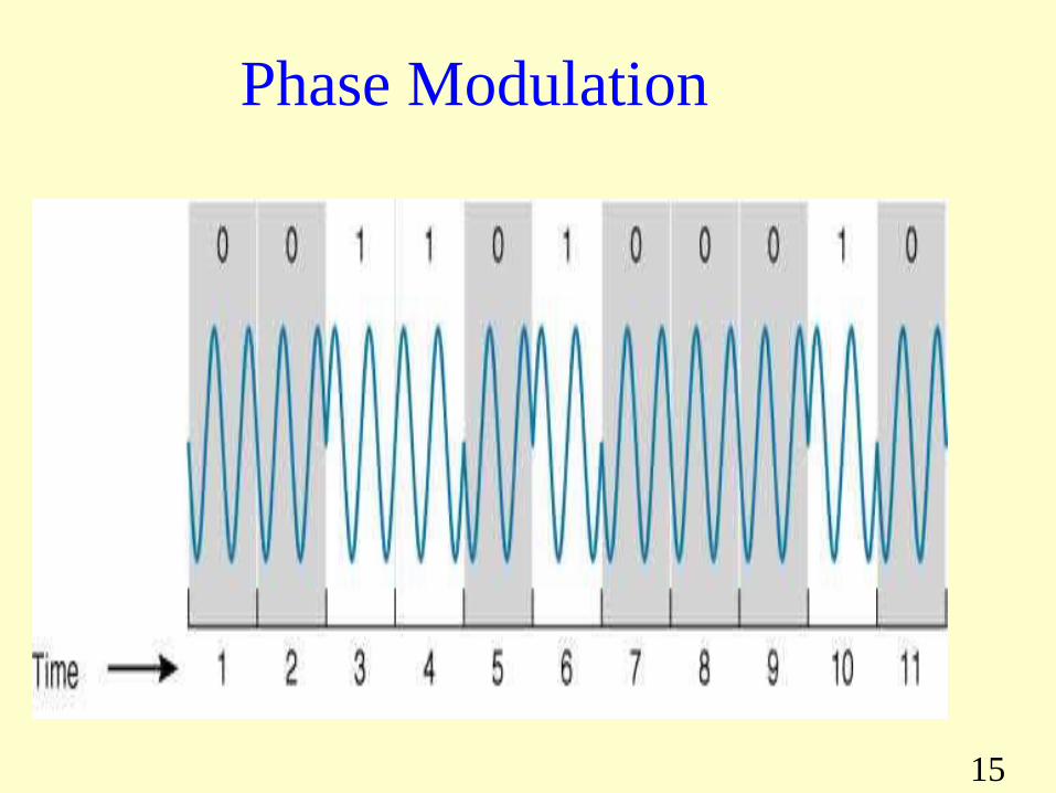
Phase ModulationPhase refers to point in each wave cycle at which the wave begins
Phase Modulation (PM)Phase Shift Keying (PSK) means changing phase of carrier wave to encode data• Next slide shows phase modulation in which one bit is encoded for each carrier wave change
Changing the carrier wave’s phase by 180o corresponds to a bit value of 1
No change in the carrier wave’s phase means a bit value of 0
15
Phase Modulation

16
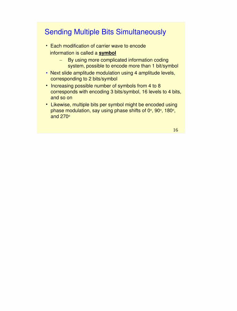
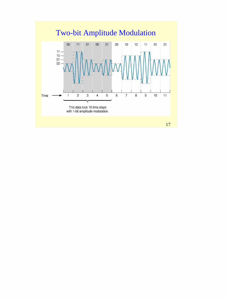
Sending Multiple Bits Simultaneously Each modification of carrier wave to encode information is called a symbol
– By using more complicated information coding system, possible to encode more than 1 bit/symbol
• Next slide amplitude modulation using 4 amplitude levels, corresponding to 2 bits/symbol
Increasing possible number of symbols from 4 to 8 corresponds with encoding 3 bits/symbol, 16 levels to 4 bits, and so on
Likewise, multiple bits per symbol might be encoded using phase modulation, say using phase shifts of 0o, 90o, 180o, and 270o

17
Two-bit Amplitude Modulation

18
Quadrature Amplitude Modulation (QAM)
QAM is family of encoding schemes widely used for encoding multiple bits per symbol that combine Amplitude and Phase Modulation 16QAM uses 8 different phase shifts and 2 different amplitude levels
Since 16 possible symbols, each symbol encodes 4 bits
QAM and related techniques are commonly used for voice modems

19
Bit Rate vs. Baud Rate (Symbol Rate)
Bit rate (or data rate) is number of bits transmitted per secondBaud rate (same as symbol rate) refers to number of symbols transmitted per secondSince multiple bits can be encoded per symbol, the two terms are not the same !!!!
General formula:Data Rate (bits/second)= Symbol Rate (symbols/sec.) x No. of bits/symbol
20
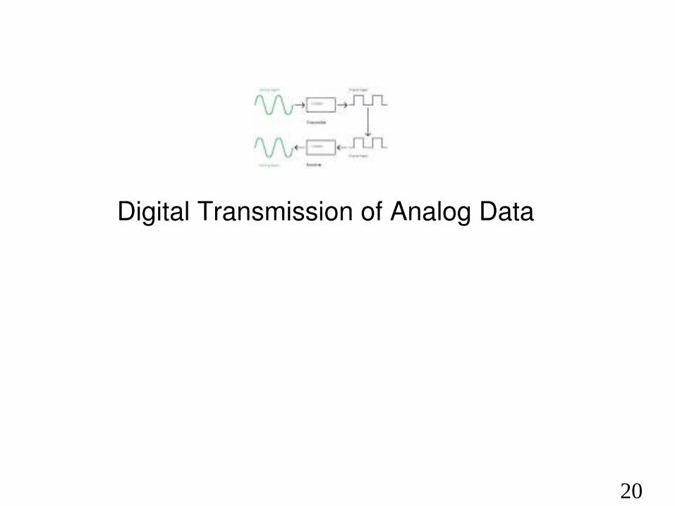
Digital Transmission of Analog Data
21
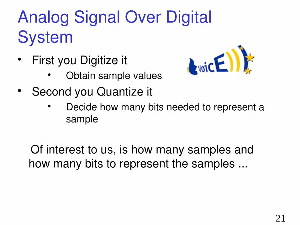
Analog Signal Over Digital System First you Digitize it
Obtain sample values Second you Quantize it
Decide how many bits needed to represent a sample
Of interest to us, is how many samples and how many bits to represent the samples ...
22
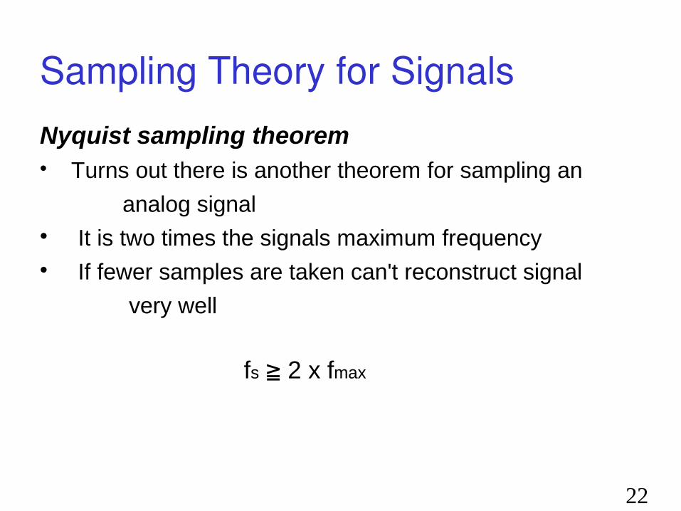
Sampling Theory for SignalsNyquist sampling theorem Turns out there is another theorem for sampling an
analog signal It is two times the signals maximum frequency If fewer samples are taken can't reconstruct signal
very well
fs ≧ 2 x fmax

4.23
Figure 4.24 Recovery of a sampled sine wave for different sampling rates

24
Enough Bits to Represent Signal Recall the Nyquist Theorem Bit Rate = 2 X Bandwidth X log2 L
L = number of signal levels Signal samples can still be large mathematical numbers Quantization makes range of signal discrete, so that
quantized signal takes on only discrete, usually finite, set of values
This is usually good enough for human ear to pick up sound

25
Enough Bits to Represent Signal With L levels need N = log2 L bits to represent
the different levels, or conversely, with N bits we can represent L = 2N levels Simplest type of quantizers are called zero
memory quantizers in which quantizing a sample is independent of other samples.
Signal amplitude is represented using some finite number of bits independent of sample time and independent of values of neighboring samples
26
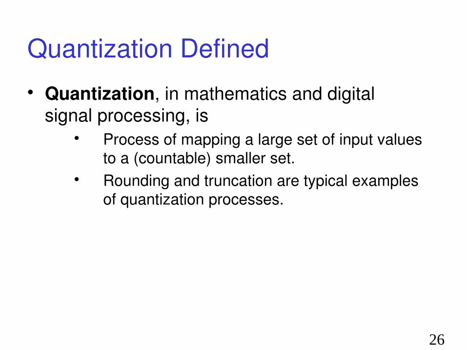
Quantization Defined Quantization, in mathematics and digital
signal processing, is Process of mapping a large set of input values
to a (countable) smaller set. Rounding and truncation are typical examples
of quantization processes.
27
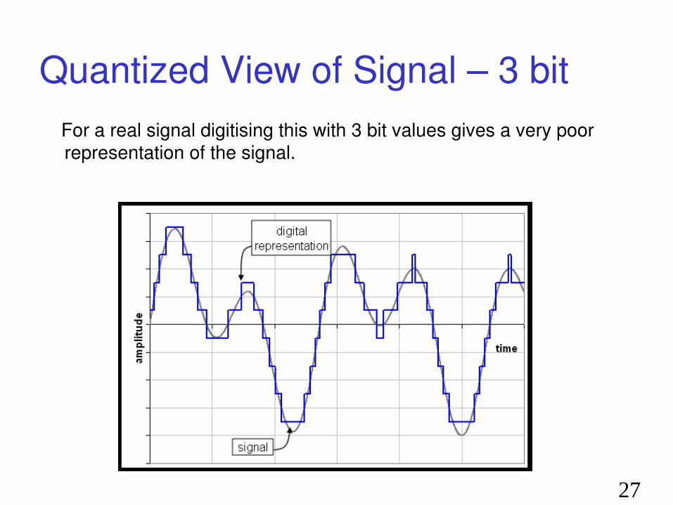
Quantized View of Signal – 3 bit For a real signal digitising this with 3 bit values gives a very poor
representation of the signal.

28
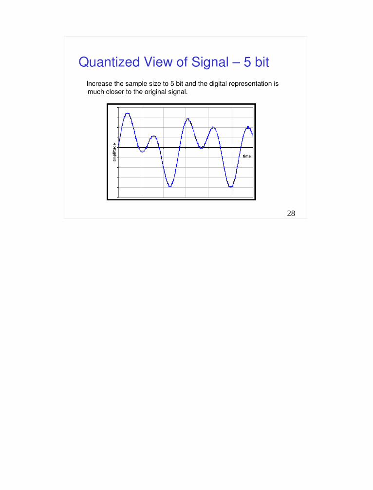
Quantized View of Signal – 5 bit Increase the sample size to 5 bit and the digital representation is
much closer to the original signal.

29
Techniques for Quantifying Analog Signals
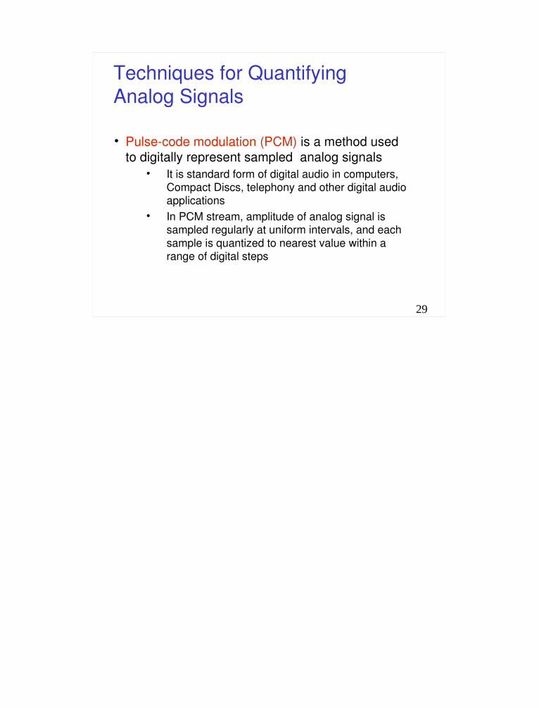
Pulse-code modulation (PCM) is a method used to digitally represent sampled analog signals
It is standard form of digital audio in computers, Compact Discs, telephony and other digital audio applications
In PCM stream, amplitude of analog signal is sampled regularly at uniform intervals, and each sample is quantized to nearest value within a range of digital steps

Pulse Code Modulation• Analog signal amplitude is sampled (measured) at
regular time intervals.
• Want to take several times maximum frequency of the analog waveform in cycles per second or hertz
• Amplitude of analog signal at each sampling is rounded off to nearest of several specific, predetermined levels
• Quantization of the signal
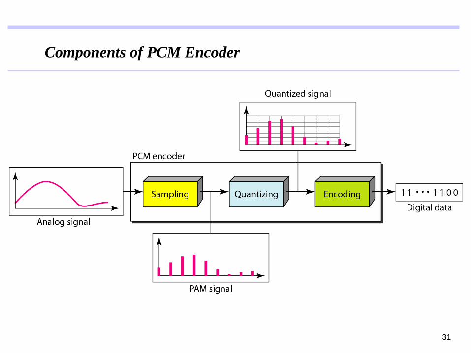
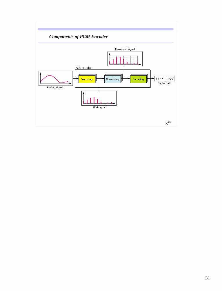
Components of PCM Encoder
31
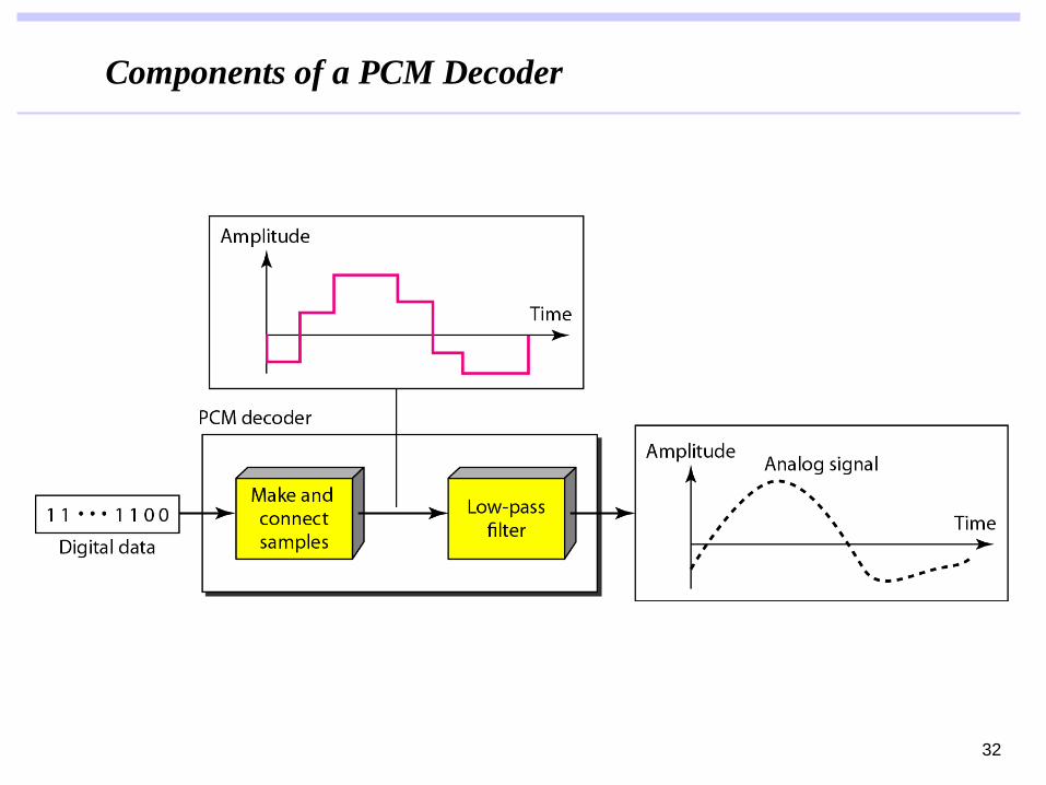
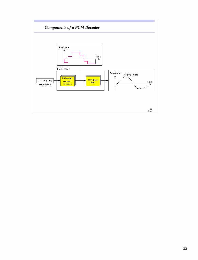
Components of a PCM Decoder
32

33
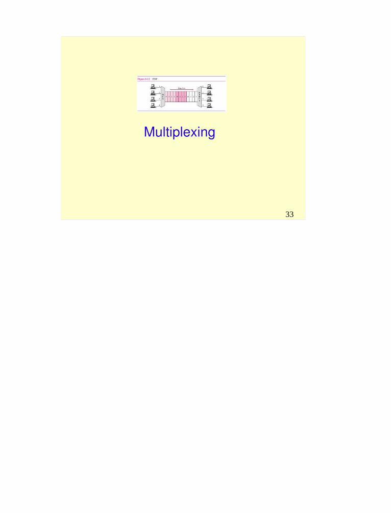
Multiplexing

34
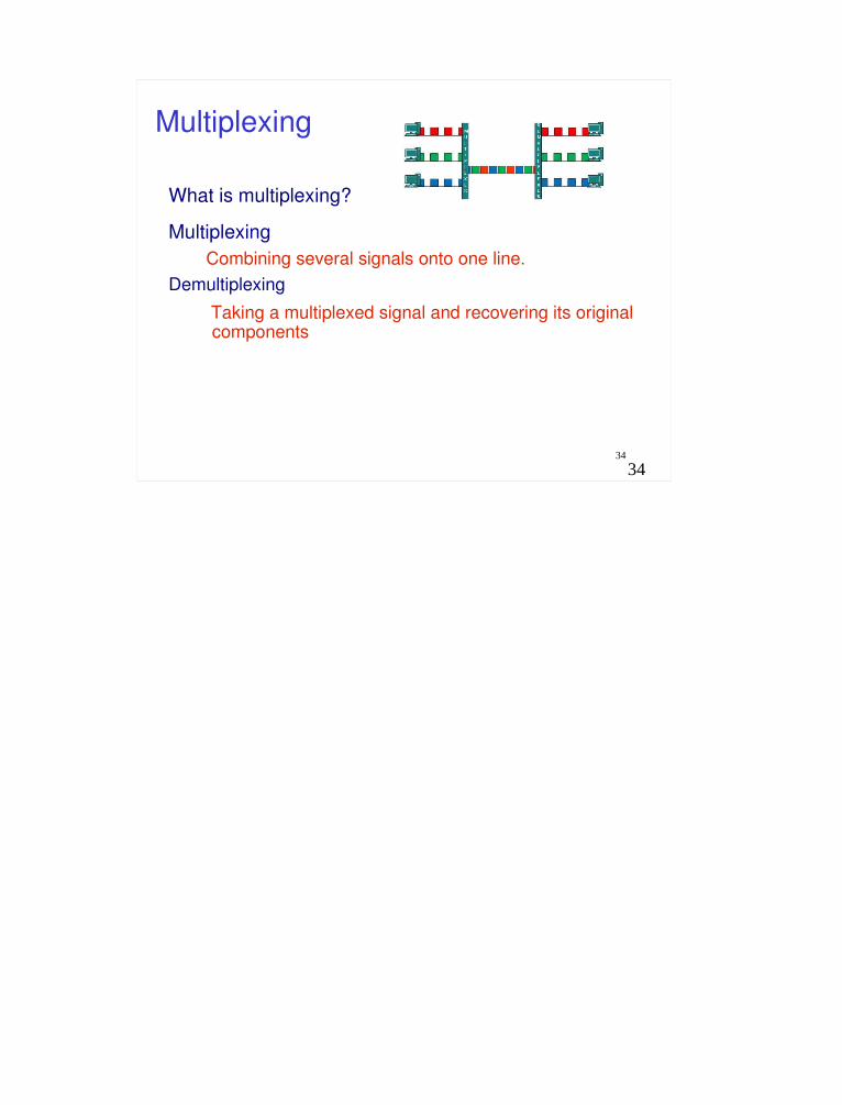
Multiplexing
What is multiplexing?
Multiplexing Combining several signals onto one line.
Demultiplexing Taking a multiplexed signal and recovering its original
components
35
Multiplexing
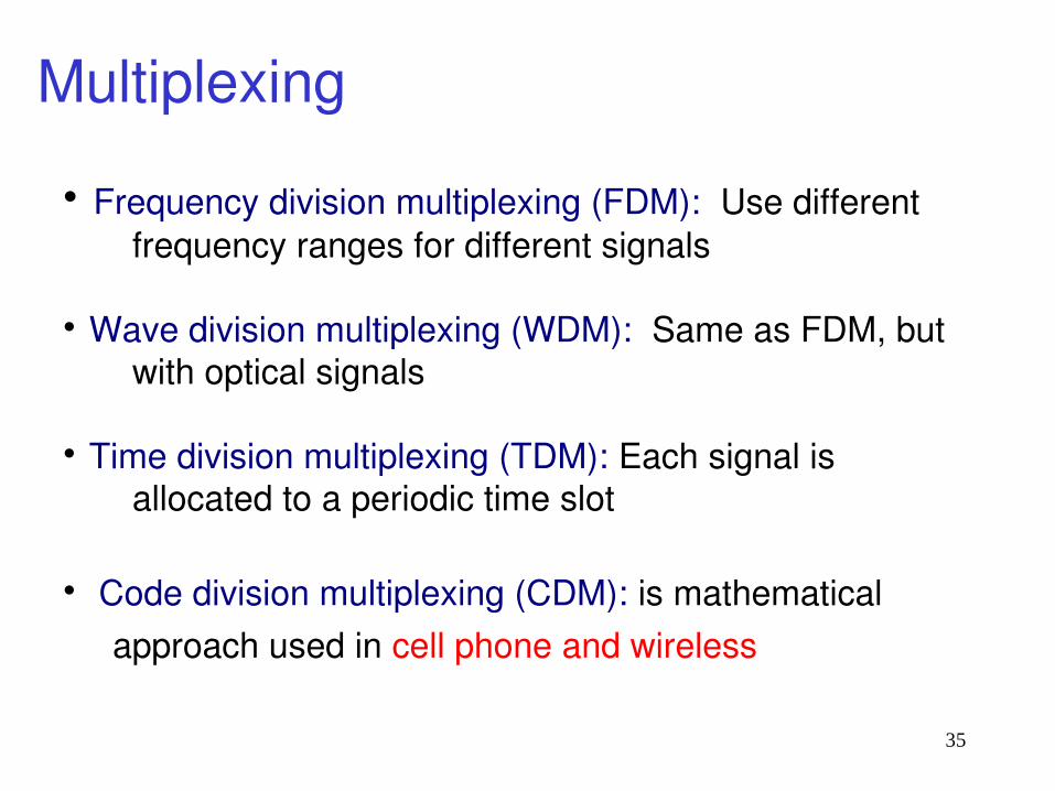
Frequency division multiplexing (FDM): Use different frequency ranges for different signals
Wave division multiplexing (WDM): Same as FDM, but with optical signals
Time division multiplexing (TDM): Each signal is allocated to a periodic time slot
Code division multiplexing (CDM): is mathematical approach used in cell phone and wireless

36
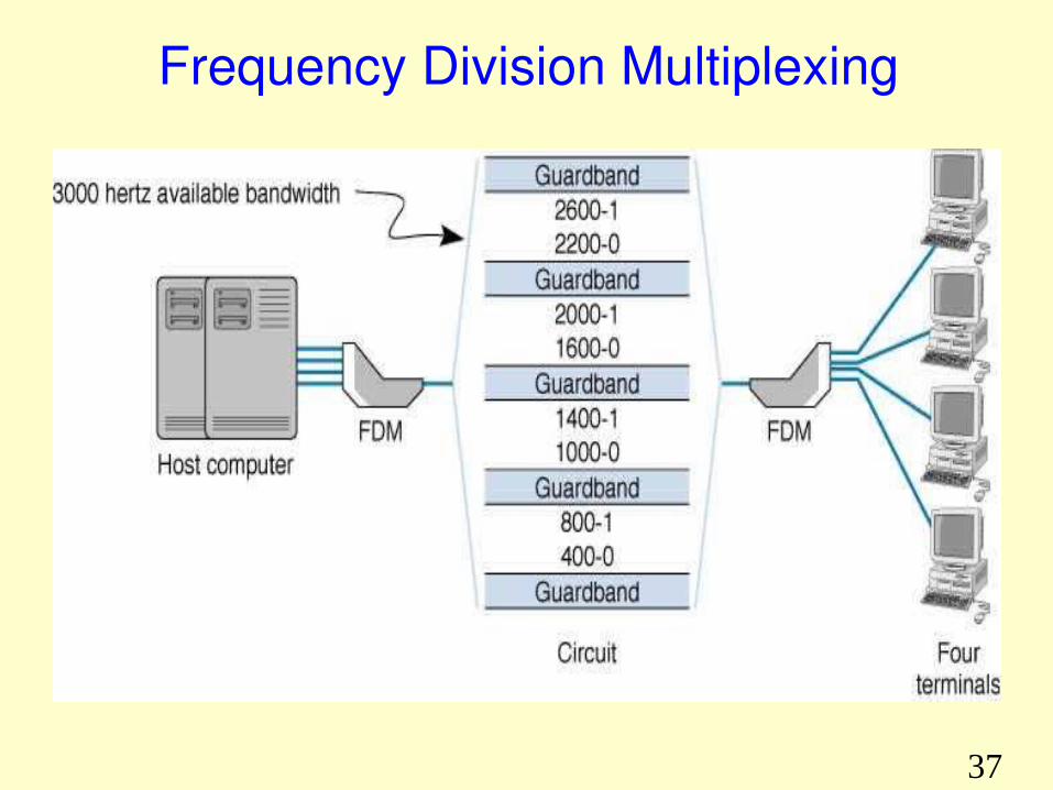
Frequency Division Multiplexing (FDM)
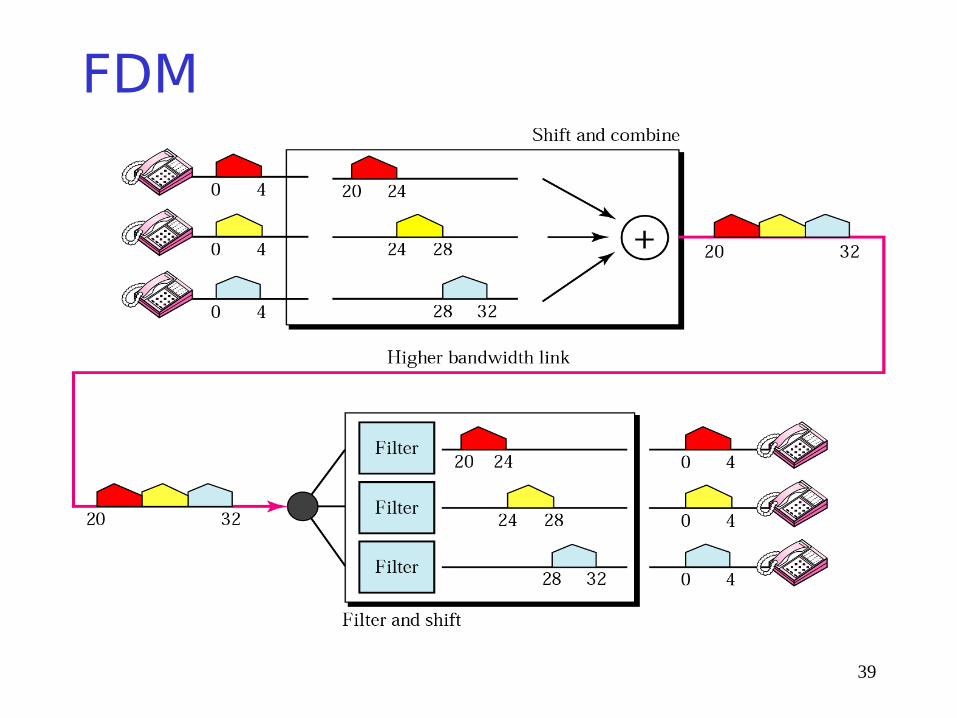
FDM works by making number of smaller channels from larger frequency band
FDM is sometimes referred to as dividing the circuit “horizontally”
In order to prevent interference between channels, unused frequency bands called guardbands separate channels
Because of guardbands, there is some wasted capacity on an FDM circuit
37
Frequency Division Multiplexing
38
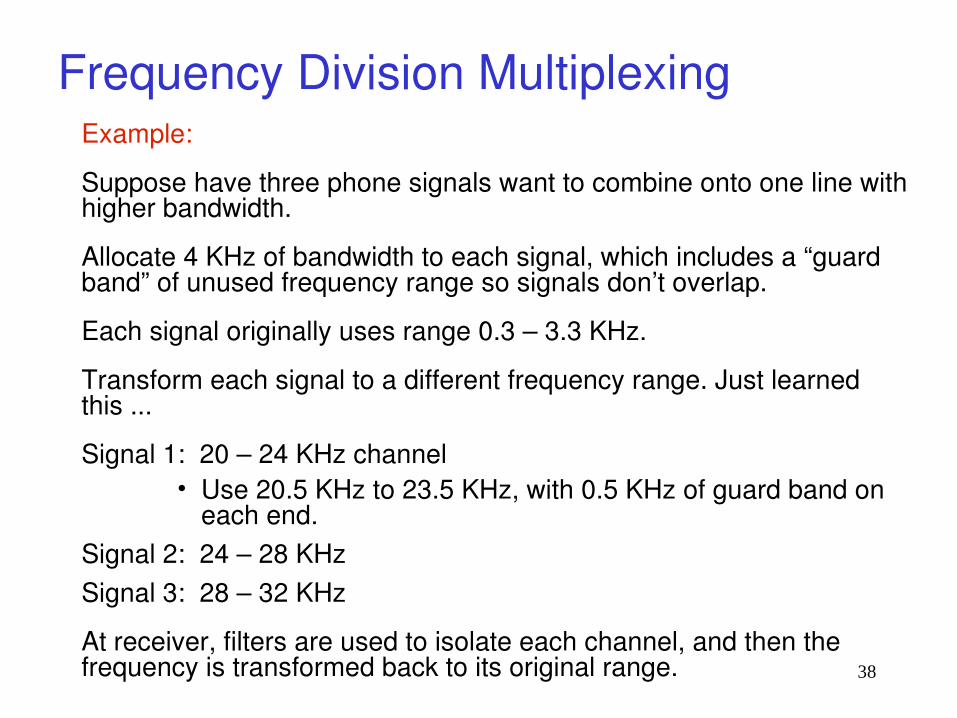
Frequency Division MultiplexingExample:
Suppose have three phone signals want to combine onto one line with higher bandwidth.
Allocate 4 KHz of bandwidth to each signal, which includes a “guard band” of unused frequency range so signals don’t overlap.
Each signal originally uses range 0.3 – 3.3 KHz.
Transform each signal to a different frequency range. Just learned this ...
Signal 1: 20 – 24 KHz channel• Use 20.5 KHz to 23.5 KHz, with 0.5 KHz of guard band on
each end.Signal 2: 24 – 28 KHzSignal 3: 28 – 32 KHz
At receiver, filters are used to isolate each channel, and then the frequency is transformed back to its original range.
39
FDM

40
FDM applicationsHigh capacity phone lines
AM radio: 530 KHz to 1700 KHz, 10 KHz bandwidth per station
FM radio: 88 MHz to 108 MHz, 200 KHz bandwidth per station
TV broadcasts: 6 MHz bandwidth per TV channel
First generation cell phones: each user got two 30 KHz channels (sending, receiving).
41
Wave Division MultiplexingEssentially same as FDM, except signals are optical and prisms are used to combine/split signals instead of electrical components.
Used to combine signals of different frequencies (i.e. colours) onto one fibre-optic cable
42
Time Division Multiplexing (TDM)
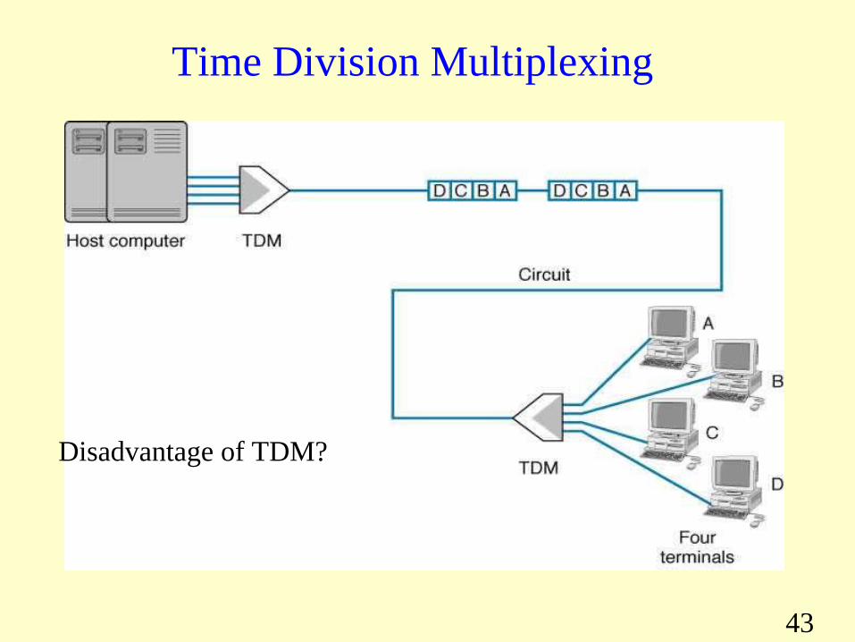
TDM allows multiple channels by allowing channels to send data by “taking turns”TDM is sometimes referred to as dividing circuit “vertically” • Next slide shows 4 terminals sharing a circuit, with
each terminal sending one character at a time• With TDM, time on circuit is shared equally each
channel gets a time slot, whether or not it has any data to send
• TDM is more efficient than FDM, since TDM doesn’t use guardbands, so entire capacity can be divided between channels
43
Time Division Multiplexing
Disadvantage of TDM?

44
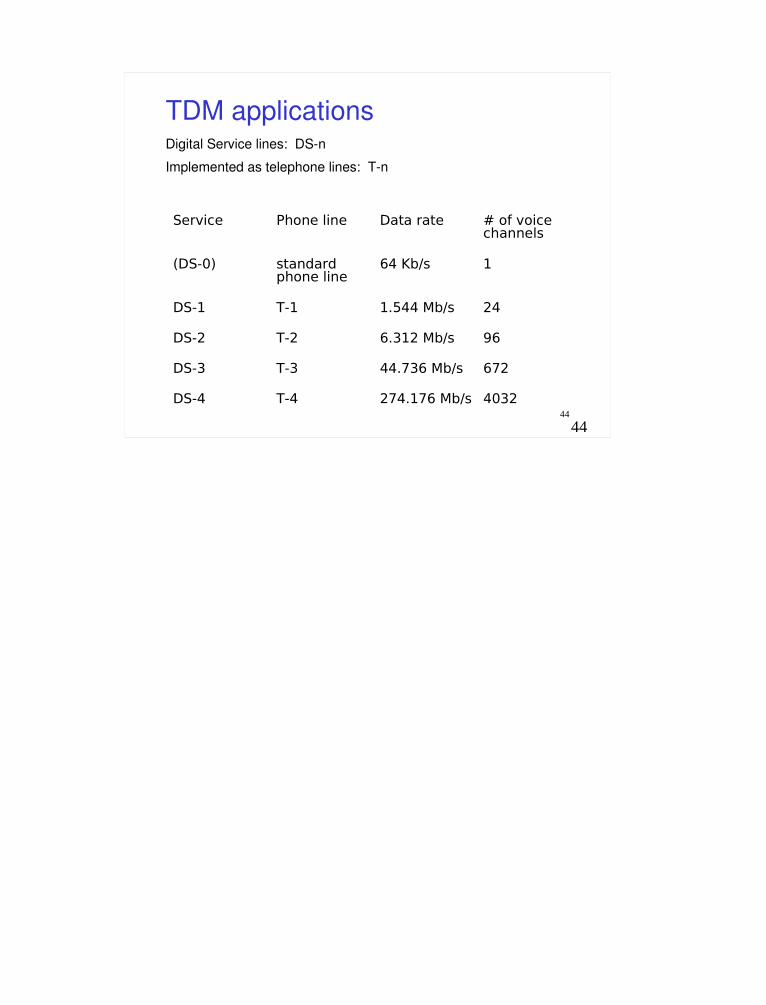
TDM applicationsDigital Service lines: DS-n
Implemented as telephone lines: T-n
Service Phone line Data rate # of voice channels
(DS-0) standard phone line
64 Kb/s 1
DS-1 T-1 1.544 Mb/s 24
DS-2 T-2 6.312 Mb/s 96
DS-3 T-3 44.736 Mb/s 672
DS-4 T-4 274.176 Mb/s 4032
45
Code Division Multiplexing (CDM)CDM used in parts of cellular telephone system and for some satellite communication
CDM relies on an interesting mathematical ideavalues from orthogonal vector spaces can be combined and separated without interferenceEach sender is assigned a unique binary code Ci that is known as a chip sequencechip sequences are selected to be orthogonal vectors
• Means dot product of any two chip sequences is zero
46
Code Division Multiplexing (CDM)
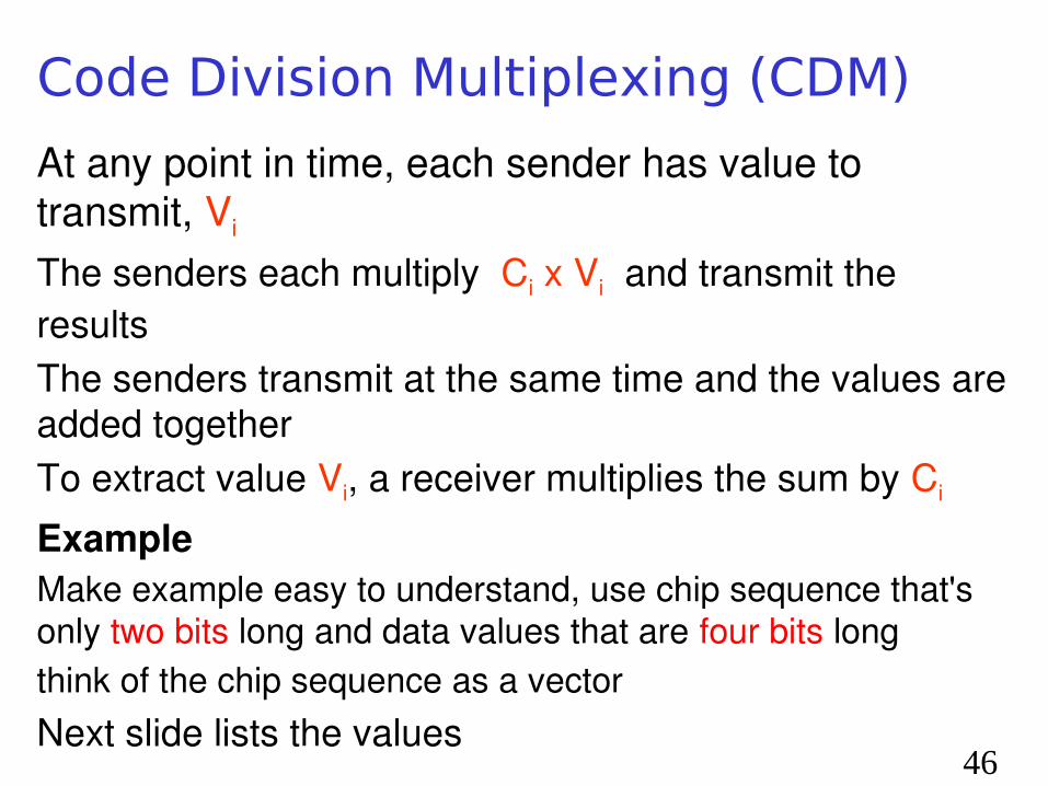
At any point in time, each sender has value to transmit, Vi The senders each multiply Ci x Vi and transmit the resultsThe senders transmit at the same time and the values are added togetherTo extract value Vi, a receiver multiplies the sum by Ci
ExampleMake example easy to understand, use chip sequence that's only two bits long and data values that are four bits longthink of the chip sequence as a vectorNext slide lists the values

47
Code Division Multiplexing
48
Code Division Multiplexing
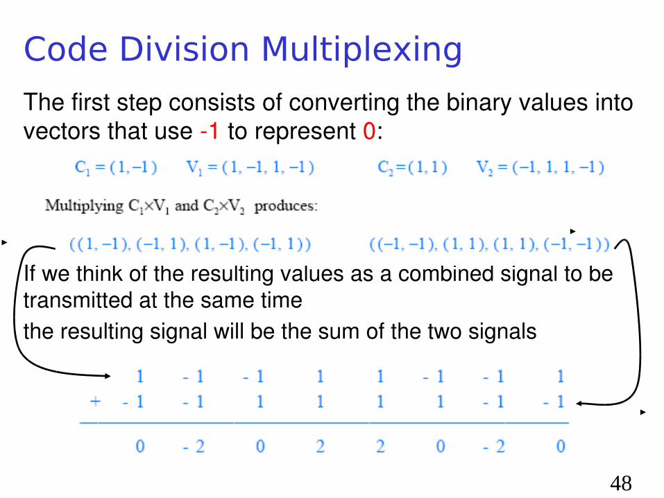
The first step consists of converting the binary values into vectors that use -1 to represent 0:
If we think of the resulting values as a combined signal to be transmitted at the same timethe resulting signal will be the sum of the two signals

49
Code Division Multiplexing A receiver treats the sequence as a vectorcomputes product of vector and the chip sequencetreats result as a sequence, and converts the result to binary by interpreting positive values as binary 1 and negative values as 0Thus, Receiver 1 computes:
Interpreting the result as a sequence produces: (2 -2 2 -2)which becomes the binary value: (1 0 1 0)note that 1010 is the correct value of V1
Receiver 2 will extract V2 from the same transmission
C1
Received data
Code division multiple access (CDMA) is a channel access method utilized by various radio communication technologies.

Summary
• Many types of encoding for sending data• Other than LAN or switch connections, most
communications require signal transforming • Multiplexing allows sharing for efficient use of
physical media• Many interesting ways to make physical
network communications more efficient

51
Keep working on HW 2

1

3
Different Types of Channels
Intended use of communication channel dictates whether Analog, Digital, Modulated or Unmodulated transmission is needed
– Radio and Cellular communications require modulating signal to fit within specific frequency ranges
– Use of telephone lines for digital data transmission requires different type of modulation to transmit digital over traditionally analog lines
Look at analog signals over digital and digital signals over analog

4
Definitions
First, need to define terms Carrier Wave Modulation Baseband and Bandpass Channels
5
5
Carrier Wave Carrier wave is pure wave of constant frequency, like a
sine wave … By itself it doesn’t carry much information To include speech or data information, another wave
needs to be imposed, called an input signal, on top of the carrier wave
Imposing an input signal onto carrier wave is called modulation.
Modulation changes shape of carrier wave to somehow
encode the speech or data we need to encode What does it mean to modulate? What kinds are there?

6
ModulationModulation is modification of carrier wave’s fundamental characteristics in order to encode informationThere are three basic ways to modulate an analog carrier wave:
Amplitude Modulation Frequency Modulation Phase Modulation

7
Baseband Channels
Baseband transmission is transmission of encoded signal using its own baseband frequencies; i.e. without any shift to higher frequency ranges, Without a shift in range of signal frequencies Signal frequencies are within band of frequencies
from near 0 hertz up to a higher cut-off frequency or maximum bandwidth
Examples: Serial cables and local area networks utilize baseband transmission

8
Passband Channel A passband channel has range of frequencies or wavelengths that can pass through a
filter In passband transmission, modulation methods are
used so that only a limited frequency range is used Typically, range does not include 0 or low frequencies
Example: Utilizedin wireless communicationand in radio transmission

9
9
Analog Transmission of Digital Data Traditional analog transmission has been
Telephone service POTS – Plain Old Telephone Service Have an existing system of wired
communication Sending digital data over telephone service –
How do we do it? Use a modem !!! Modems use carrier waves to send
information Known as modulation ….

10
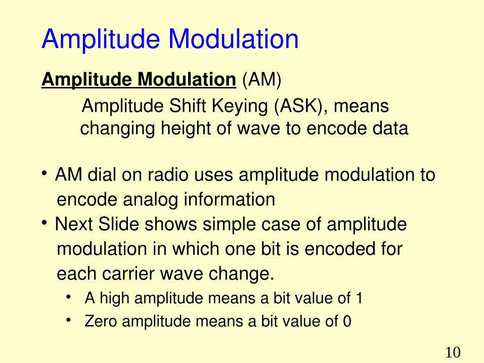
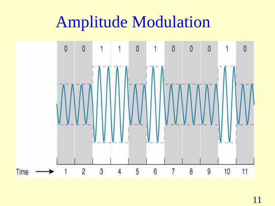
Amplitude ModulationAmplitude Modulation (AM)
Amplitude Shift Keying (ASK), means changing height of wave to encode data
AM dial on radio uses amplitude modulation to encode analog information Next Slide shows simple case of amplitude modulation in which one bit is encoded for each carrier wave change.
A high amplitude means a bit value of 1 Zero amplitude means a bit value of 0
11
Amplitude Modulation

12
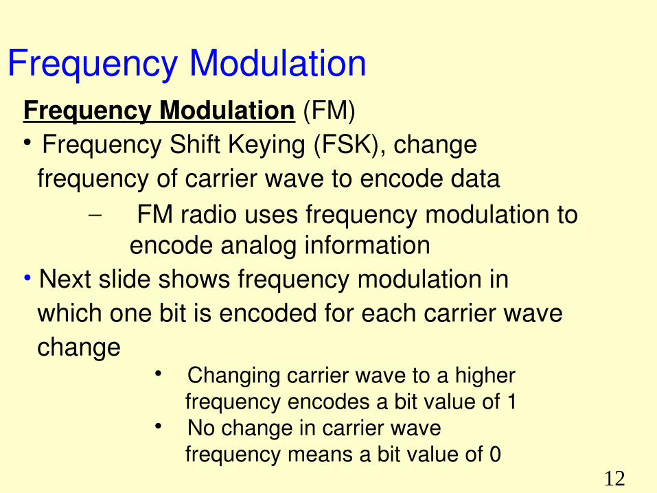
Frequency ModulationFrequency Modulation (FM) Frequency Shift Keying (FSK), change frequency of carrier wave to encode data
– FM radio uses frequency modulation to encode analog information
• Next slide shows frequency modulation in which one bit is encoded for each carrier wave change
Changing carrier wave to a higher frequency encodes a bit value of 1 No change in carrier wave frequency means a bit value of 0
13
Frequency Modulation

14
Phase ModulationPhase refers to point in each wave cycle at which the wave begins
Phase Modulation (PM)Phase Shift Keying (PSK) means changing phase of carrier wave to encode data• Next slide shows phase modulation in which one bit is encoded for each carrier wave change
Changing the carrier wave’s phase by 180o corresponds to a bit value of 1
No change in the carrier wave’s phase means a bit value of 0

15
Phase Modulation
16
Sending Multiple Bits Simultaneously Each modification of carrier wave to encode information is called a symbol
– By using more complicated information coding system, possible to encode more than 1 bit/symbol
• Next slide amplitude modulation using 4 amplitude levels, corresponding to 2 bits/symbol
Increasing possible number of symbols from 4 to 8 corresponds with encoding 3 bits/symbol, 16 levels to 4 bits, and so on
Likewise, multiple bits per symbol might be encoded using phase modulation, say using phase shifts of 0o, 90o, 180o, and 270o
17
Two-bit Amplitude Modulation
18
Quadrature Amplitude Modulation (QAM)
QAM is family of encoding schemes widely used for encoding multiple bits per symbol that combine Amplitude and Phase Modulation 16QAM uses 8 different phase shifts and 2 different amplitude levels
Since 16 possible symbols, each symbol encodes 4 bits
QAM and related techniques are commonly used for voice modems

19
Bit Rate vs. Baud Rate (Symbol Rate)
Bit rate (or data rate) is number of bits transmitted per secondBaud rate (same as symbol rate) refers to number of symbols transmitted per secondSince multiple bits can be encoded per symbol, the two terms are not the same !!!!
General formula:Data Rate (bits/second)= Symbol Rate (symbols/sec.) x No. of bits/symbol
20
Digital Transmission of Analog Data
21
Analog Signal Over Digital System First you Digitize it
Obtain sample values Second you Quantize it
Decide how many bits needed to represent a sample
Of interest to us, is how many samples and how many bits to represent the samples ...

22
Sampling Theory for SignalsNyquist sampling theorem Turns out there is another theorem for sampling an
analog signal It is two times the signals maximum frequency If fewer samples are taken can't reconstruct signal
very well
fs ≧ 2 x fmax

23

24
Enough Bits to Represent Signal Recall the Nyquist Theorem Bit Rate = 2 X Bandwidth X log2 L L = number of signal levels Signal samples can still be large mathematical numbers Quantization makes range of signal discrete, so that
quantized signal takes on only discrete, usually finite, set of values
This is usually good enough for human ear to pick up sound

25
Enough Bits to Represent Signal With L levels need N = log2 L bits to represent
the different levels, or conversely, with N bits we can represent L = 2N levels Simplest type of quantizers are called zero
memory quantizers in which quantizing a sample is independent of other samples.
Signal amplitude is represented using some finite number of bits independent of sample time and independent of values of neighboring samples
26
Quantization Defined Quantization, in mathematics and digital
signal processing, is Process of mapping a large set of input values
to a (countable) smaller set. Rounding and truncation are typical examples
of quantization processes.

27
Quantized View of Signal – 3 bit For a real signal digitising this with 3 bit values gives a very poor
representation of the signal.
28
Quantized View of Signal – 5 bit Increase the sample size to 5 bit and the digital representation is
much closer to the original signal.
29
Techniques for Quantifying Analog Signals
Pulse-code modulation (PCM) is a method used to digitally represent sampled analog signals
It is standard form of digital audio in computers, Compact Discs, telephony and other digital audio applications
In PCM stream, amplitude of analog signal is sampled regularly at uniform intervals, and each sample is quantized to nearest value within a range of digital steps

31
31
Components of PCM Encoder
31
32
32
Components of a PCM Decoder
32
33
Multiplexing
3434
Multiplexing
What is multiplexing?
Multiplexing Combining several signals onto one line.
Demultiplexing Taking a multiplexed signal and recovering its original
components

3535
Multiplexing
Frequency division multiplexing (FDM): Use different frequency ranges for different signals
Wave division multiplexing (WDM): Same as FDM, but with optical signals
Time division multiplexing (TDM): Each signal is allocated to a periodic time slot
Code division multiplexing (CDM): is mathematical approach used in cell phone and wireless

36
Frequency Division Multiplexing (FDM)
FDM works by making number of smaller channels from larger frequency band
FDM is sometimes referred to as dividing the circuit “horizontally”
In order to prevent interference between channels, unused frequency bands called guardbands separate channels
Because of guardbands, there is some wasted capacity on an FDM circuit

37
Frequency Division Multiplexing

3838
Frequency Division MultiplexingExample:
Suppose have three phone signals want to combine onto one line with higher bandwidth.
Allocate 4 KHz of bandwidth to each signal, which includes a “guard band” of unused frequency range so signals don’t overlap.
Each signal originally uses range 0.3 – 3.3 KHz.
Transform each signal to a different frequency range. Just learned this ...
Signal 1: 20 – 24 KHz channel• Use 20.5 KHz to 23.5 KHz, with 0.5 KHz of guard band on
each end.Signal 2: 24 – 28 KHzSignal 3: 28 – 32 KHz
At receiver, filters are used to isolate each channel, and then the frequency is transformed back to its original range.

3939
FDM

4040
FDM applicationsHigh capacity phone lines
AM radio: 530 KHz to 1700 KHz, 10 KHz bandwidth per station
FM radio: 88 MHz to 108 MHz, 200 KHz bandwidth per station
TV broadcasts: 6 MHz bandwidth per TV channel
First generation cell phones: each user got two 30 KHz channels (sending, receiving).

4141
Wave Division MultiplexingEssentially same as FDM, except signals are optical and prisms are used to combine/split signals instead of electrical components.
Used to combine signals of different frequencies (i.e. colours) onto one fibre-optic cable

42
Time Division Multiplexing (TDM)
TDM allows multiple channels by allowing channels to send data by “taking turns”TDM is sometimes referred to as dividing circuit “vertically” • Next slide shows 4 terminals sharing a circuit, with
each terminal sending one character at a time• With TDM, time on circuit is shared equally each
channel gets a time slot, whether or not it has any data to send
• TDM is more efficient than FDM, since TDM doesn’t use guardbands, so entire capacity can be divided between channels

43
Time Division Multiplexing
Disadvantage of TDM?
4444
TDM applicationsDigital Service lines: DS-n
Implemented as telephone lines: T-n
Service Phone line Data rate # of voice channels
(DS-0) standard phone line
64 Kb/s 1
DS-1 T-1 1.544 Mb/s 24
DS-2 T-2 6.312 Mb/s 96
DS-3 T-3 44.736 Mb/s 672
DS-4 T-4 274.176 Mb/s 4032
45
Code Division Multiplexing (CDM)CDM used in parts of cellular telephone system and for some satellite communication
CDM relies on an interesting mathematical ideavalues from orthogonal vector spaces can be combined and separated without interferenceEach sender is assigned a unique binary code Ci that is known as a chip sequencechip sequences are selected to be orthogonal vectors
• Means dot product of any two chip sequences is zero
45

46
Code Division Multiplexing (CDM)
At any point in time, each sender has value to transmit, Vi The senders each multiply Ci x Vi and transmit the resultsThe senders transmit at the same time and the values are added togetherTo extract value Vi, a receiver multiplies the sum by Ci
ExampleMake example easy to understand, use chip sequence that's only two bits long and data values that are four bits longthink of the chip sequence as a vectorNext slide lists the values
46

47
Code Division Multiplexing
47

48
Code Division Multiplexing
The first step consists of converting the binary values into vectors that use -1 to represent 0:
If we think of the resulting values as a combined signal to be transmitted at the same timethe resulting signal will be the sum of the two signals
48

49
Code Division Multiplexing A receiver treats the sequence as a vectorcomputes product of vector and the chip sequencetreats result as a sequence, and converts the result to binary by interpreting positive values as binary 1 and negative values as 0Thus, Receiver 1 computes:
Interpreting the result as a sequence produces: (2 -2 2 -2)which becomes the binary value: (1 0 1 0)note that 1010 is the correct value of V1
Receiver 2 will extract V2 from the same transmission
C1
Received data
Code division multiple access (CDMA) is a channel access method utilized by various radio communication technologies.
49

