intro to gns3 and static routing -...
TRANSCRIPT

Intro to GNS3 and Static Routing
GNS3 is a virtualization platform for some Cisco and Juniper routers. Switching support is very limited
but the routing support is great for testing configurations. This lab will get you up and running with
GNS3 and teach you how to set up a basic topology using static routes. You can download GNS3 either
from their web site or using your package manager if you are on Linux. Below you will find some helpful
links. GNS3 is very easy to pick up so you probably won’t need the quick start documentation but it is
provided. Knowledge of subnets is required for this class and every lab we do so a refresher
documented is linked below.
GNS3 Quick start guide
IP Addressing and Subnetting for New Users (Cisco)
Cisco Command Line Interface Guide
1) Intro to GNS3
2) Adding devices to workspace
3) Starting and setting IDLE PC values
4) Console Into and Configure IP Addresses For Connected Interfaces
5) Setting up Static Routes
6) Turn In
Intro to GNS3 Below is an image of a blank GNS3 workspace. There are three critical areas you should focus on here,
Available Devices, Workspace, and Topology Summary. These three areas are going to be the most
important to us. You should get familiar with other areas but for most of the labs we will focus on these
three. Available devices has a list of what devices GNS3 supports, we will be using the Router 3600
images throughout this quarter (router images are not free however because they no longer sell the
3640 we are allowed to use them for as many soft installs as we want for free). Your workspace is
where you will drag and connect your routers together. This will give you a good visual of your topology
and allow you to interact with the routers. As you add routers to your workspace they begin to show up
in your topology summary.

Adding Devices to Workspace Let’s start by adding 5 Router 3600 to the workspace like the image below and you should see your
summary automatically fill up with red dots. Red is off and Green is on. Now from here we need to add
some interfaces to the routers. Highlight all the routers and right click then configure.
Available
Devices Workspace
Topology
Summary

Add four Fast Ethernet interfaces to each router. From here we will be able to connect each device and
start them up. To connect each device click the circled button in the image below and connect them the
same way as the image shows. The two buttons to the left of the ‘link’ button will toggle the names of

the router and interfaces on and off. This is useful when building your topology to know exactly what
interfaces are connected to what.
To start your routers you can either start them individually by right clicking each one and hitting start or
you can click the play button on the toolbar which will start each on.
Starting and Setting IDLE PC Values Making sure your IDLE PC times are correct for each router is extremely important to the efficiency of
your router and the stability of your computer. When you initially start a router it will consume 100%
CPU and continue to do so unless you set proper IDLE PC values. I have done this for you in the lab but
they still need verification. Bring up your system monitor and look at the CPU percentage used. With
five routers it shouldn’t be more than about 10%-20% depending on your machine.
To set a new IDLE PC value right click any router and hit IDLE PC. This will take a few seconds to
compute a good IDLE PC value for you. Once done you should see a dropdown box with several
addresses in them. Select the one with the asterisk next to it. If you are having trouble getting an
acceptable value sometimes just trying random values will get a good IDLE PC value for your machine.
Now that your IDLE PC values are good and each router is started up and connected you should have a
workspace like the image below.

Console Into and Configure IP Addresses for Connected Interfaces From here we will start to configure each routers connected interfaces with IP addresses. It is always
good practice to plan out your IP address before setting them. This is helpful in preventing the case
where you could run out of addresses for a specific network and also makes your life easier when
configuring multiple devices. For this lab we will subnet a class A network out. You can label your
topology by clicking ‘Add Note’ button in the GNS3 toolbar. Set your notes up like the image below.
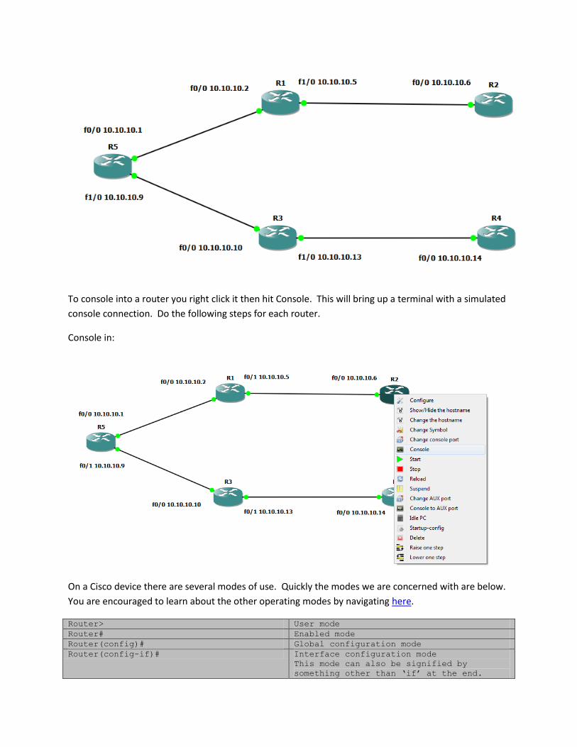
To console into a router you right click it then hit Console. This will bring up a terminal with a simulated
console connection. Do the following steps for each router.
Console in:
On a Cisco device there are several modes of use. Quickly the modes we are concerned with are below.
You are encouraged to learn about the other operating modes by navigating here.
Router> User mode
Router# Enabled mode
Router(config)# Global configuration mode
Router(config-if)# Interface configuration mode
This mode can also be signified by
something other than ‘if’ at the end.
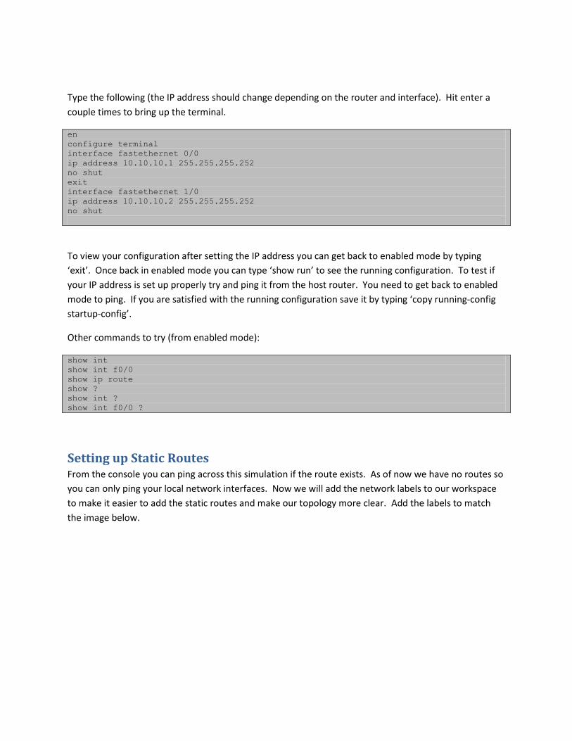
Type the following (the IP address should change depending on the router and interface). Hit enter a
couple times to bring up the terminal.
en
configure terminal
interface fastethernet 0/0
ip address 10.10.10.1 255.255.255.252
no shut
exit
interface fastethernet 1/0
ip address 10.10.10.2 255.255.255.252
no shut
To view your configuration after setting the IP address you can get back to enabled mode by typing
‘exit’. Once back in enabled mode you can type ‘show run’ to see the running configuration. To test if
your IP address is set up properly try and ping it from the host router. You need to get back to enabled
mode to ping. If you are satisfied with the running configuration save it by typing ‘copy running-config
startup-config’.
Other commands to try (from enabled mode):
show int
show int f0/0
show ip route
show ?
show int ?
show int f0/0 ?
Setting up Static Routes From the console you can ping across this simulation if the route exists. As of now we have no routes so
you can only ping your local network interfaces. Now we will add the network labels to our workspace
to make it easier to add the static routes and make our topology more clear. Add the labels to match
the image below.
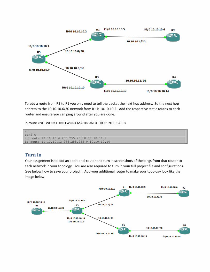
To add a route from R5 to R1 you only need to tell the packet the next hop address. So the next hop
address to the 10.10.10.6/30 network from R1 is 10.10.10.2. Add the respective static routes to each
router and ensure you can ping around after you are done.
ip route <NETWORK> <NETWORK MASK> <NEXT HOP INTERFACE>
en
conf t
ip route 10.10.10.4 255.255.255.0 10.10.10.2
ip route 10.10.10.12 255.255.255.0 10.10.10.10
Turn In Your assignment is to add an additional router and turn in screenshots of the pings from that router to
each network in your topology. You are also required to turn in your full project file and configurations
(see below how to save your project). Add your additional router to make your topology look like the
image below.

Please save your project and make sure to check the ‘Save IOS startup configurations’. Be sure to save
your running configs to startup configs to ensure everything saves correctly.