1. description - free instruction manuals
TRANSCRIPT

1. Description
Sanicom is a lifting pump for wastewater used in commercial applications (restaurants, hairdressing salons, the catering industry etc.). The unit operates automatically, has a high performance level, and is safe and reliable, provided all the rules for installation and maintenance in this notice are strictly followed. Especially those indicated by:
Failure to comply with this instruction could endanger the safety of persons
Indication that a risk of electrical origin exists
Electrical installation must be carried out by a professional electrician.
“Attention” Failure to comply with this instruction could endanger the safe functioning of the apparatus.
2. List of Accessories included
25 x 40
A B C D
E F G H
I
x2 x1 x2 x2
x1 x1 x2 x2
x1
Hose clip Hose clip
Inlet Cover Hose clip Screw Plug
Elbow
Hose clipFlexible inlet connector
For any additional information, please contact our customer service department.
32 x 50 50 x 70
40 x 60
Please also see “10 golden rules” for correct Saniflo installation on www.saniflo.co.uk
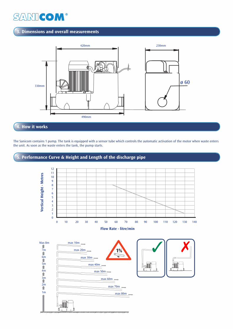
3. Dimensions and overall measurements
4. How it works
The Sanicom contains 1 pump. The tank is equipped with a sensor tube which controls the automatic activation of the motor when waste enters the unit. As soon as the waste enters the tank, the pump starts.
5. Performance Curve & Height and Length of the discharge pipe
Flow Rate - litre/min
Ver
tica
l Hei
ght
- Met
res
0 10 20 30 40 50 60 70 80 90 100 110 120 130 140
1211109876 5 4 3 2 1 0
max 10m
3 7
4m
3m
2m
1m
5m
6m
7m 1%
Max 8m
max 20m
max 30m
max 40m
max 50m
max 60m
max 70m
max 80m
420mm
330mm
490mm
ø 60
230mm

6. Technical Data & Application
7. Installation
FITTING
The Sanicom can be fixed to the floor, preventing it from turning or moving.
1. Warning: The space in which the Sanicom is installed must be large enough to leave at least 600mm around the unit for easy maintenance. This space must be well lit, ventilated, and must never be immersed in water and must be protected from frost.
2. Isolation valves should be fitted to the inlet pipework and discharge pipework to isolate the unit in case of the need for service.
Application Commercial sink, washing machine, dishwasher or shower* or bath*
Type FF03-P95
Maximum vertical pumping height 8m
Voltage 220 – 240 V
Frequency 50 Hz
Maximum power consumption 750 W
Maximum current consumption 3.3 A
Electrical class I
Protection index IP44
Max temp with intermittent functioning 80°
Net weight 10 kg
* In the case of bath or shower tray, make sure the waste traps are raised 15cm above floor level.
CAUTION: 1. All applications other than those described in this notice are prohibited. 2. Do not exceed an incoming flow rate greater than 80% of the flow rate stated on the design curve in any of the apparatus.
8. Connection to side inlets
Use the flexible inlet connector (A) for side inlet connections. Using a metalwork saw, saw off the desired inlet point, remove any burrs and then fix the flexible inlet connector with the hose clip (D).
We recommend the installation of a grease trap for installations with a high grease inflow.
Connection to the inlet can be made using a 40mm or 50mm pipe. To make a 50mm connection, cut off the end of sleeve (A) beforehand.
H HG
G
I
C
A D

To connect a bathtub (or shower), make sure the waste trap height is raised by at least 15cm above floor level. Connection must be made using 40mm or 50mm diameter pipework, with minimum slope of 1%.
The disposal of waste from the Sanicom can discharged through a 32mm diameter copper or plastic pipes (or PVC, ABS, etc.).
This discharge pipe must be designed so as to prevent back-flow from the sewers. See diagram above.
Horizontal discharge pipework should maintain a 1% fall (1cm/M) to the soil and vent pipe. If a vertical rise is required, this must be installed at the start of the run, before the horizontal section. The horizontal section should then have a minimum 1% fall to the final drain point.
Take care that the discharge valve flap faces the direction of flow.
If the end of the discharge pipework is much lower than the unit, install a riser pipe about 80mm long from the highest point of the discharge run and fit an air admittance pipe on top (capable of withstanding at least 15psi pressure.) to break the syphon.
The discharge should be connected to a 100mm discharge stack via a strap boss connector.
9. Connection to sanitary ware
10. Connection to soil and vent pipe or drain
150mm min
1%
40m
m
32m
m
2.5% 2.5%

11. In case a service is needed
Allow for a drain-off point at the bottom of the rising discharge pipe. Ensure that the unit is easily accessible for possible maintenance.
13. Standard
Sanicom conforms to Standard EN 12050-2. Lifting station for waste products not containing faecal matter.
SANICOM®Société Française d’AssainissementEN 12050-2/03FF03-P95220 - 240 V - 50 Hz - 750 W - IP44
12. Electrical connection
14. Alarm
There is the option of connecting an alarm (light, bell) on to the electronic circuit board (2 terminals fed with 220V). If the motor is run continuously (more than 5 minutes), the contact will be made. This enables the user to carry out a check if he wishes.
Connection of the alarmTwo 6.35 push on connection points are available on the electronic circuit board (arrowed) for creating an alarm circuit. (These connectors have a 220V, 0.5A maximum current passing through them). To access them after turning the power off, remove the cover then unscrew and unclip the upper casing of the electronic box, to expose the electronic circuit board. On this card use the point marked E.V. and the unused neutral connection point marked N. Use a round 2 x 0.75mm 2 wire, which must pass across the lid of the upper casing, through the cable gland, before being connected to the chosen alarm system.
The electrical installation should be carried out by a qualified person.
All wiring must conform to BS7671, 1992 requirements for electrical installations. The Sanicom requires a 220/240V single phase AC 50 Hz supply (UK specification). Do not connect the Sanicom to a conventional plug and socket. It must be wired into a fused, unswitched, fixed wiring connector fitted with a 5 amp fuse. The Sanicom has an earth wire. The wires in the mains lead are coloured in accordance with the following code:
Brown – Live Blue – Neutral Green/Yellow – Earth
Warning: Ensure the electricity is turned OFF at the main switchboard before wiring to connector.
All work on cable, pressure chamber and motor should only be carried out by a qualified Saniflo servicing agent, as special tools are required.
UK – 230/240V 50Hz.
The unit should be installed so it is easily accessible/removable for possible maintenance. The unit should not be exposed to splashing in normal use.
CANADAUSA
EUR
CH
GB

15. Commissioning
Once the hydraulic and electrical connections have been made, check that the connections are tight by allowing water to flow through each entry point used. Ensure that the pump is working properly.
16. Use
Sanicom is designed for disposing of wastewater originating from a commercial sink, washing machine, dishwasher, shower or bath and basin.
Sanicom can pump out hot water upto 85°C for short periods only (eg. glass washer cycle etc.)
CAUTION:
1. Do not dispose of chemical products (acids, solvents, oils, etc.) into the items connected to the Sanicom.
2. In the event of power failure, stop all water flow to the appliances connected to the Sanicom.
17. Troubleshooting
ELECTRICAL INSTALLATION MUST BE CARRIED OUT BY A PROFESSIONAL ELECTRICIAN
SYMPTOMS PROBABLE CAUSES REMEDIES
• Motor does not start• The appliance is not switched on• The cable is defective
• Check the electrical installation
• The alarm sounds• Pump is blocked• Pump Jammed• To much water flowing through
• Call a service engineer• Call a service engineer• Reduce water inflow
ELECTRICAL INSTALLATION MUST BE CARRIED OUT BY A PROFESSIONAL ELECTRICIANBefore carrying out any service work always disconnect power supply.
SYMPTOMS PROBABLE CAUSES REMEDIES
• Motor does not start• Pressure reader tube kinked or out of position• Electronic card defective
• Check the electrical installation• Call a service engineer
• Pumps working constantly• Vertical discharge too high• Electronic card defective
• Check Installation• Call a service engineer
• Alarm Sounding
• Pump blocked• Pump jammed• Electrical problems with motor• Too much water flowing through• Electronic card defective
• Call a service engineer• If the pump revolves but does not
pump, call a service engineer
• Intermittent start-up of pumps • The non-return valve broken or leaking• Clean or change the valve or call a
service engineer
FIRST LEVEL TROUBLESHOOTING
SECONDARY LEVEL TROUBLESHOOTING
18. Warranty
Sanicom SFA is guaranteed for 2 years for labour and parts, subject to correct installation and use of the apparatus.

19. Parts