1 hydronic heating/cooling pressure test & commissioning ... · pdf file1 project design /...
TRANSCRIPT
1
Proj
ect D
esig
n / T
est L
ogs
1 HYDRONIC HEATING/COOLING PRESSURE TEST & COMMISSIONING PROCEDURE Pressure Test Principles 2
Pressure Test Log for REHAU Hydronic Floor Heating/Cooling with the Test Medium Water 4
Pressure Test Log for REHAU Hydronic Floor Heating/Cooling with the Test Medium Air or Inert Gas 5
Functional Heating/Cooling Log for REHAU Hydronic Floor Heating/Cooling 6
Pressure Test Log for REHAU Concrete Core Tempering / 1st Pressure Test with the Test Medium Water 7
Pressure Test Log for REHAU Concrete Core Tempering / 2nd Pressure Test with the Test Medium Water 8
Pressure Test Log for REHAU Concrete Core Tempering / 1st Pressure Test with the Test Medium Air or Inert Gas 9
Pressure Test Log for REHAU Concrete Core Tempering / 2nd Pressure Test with the Test Medium Air or Inert Gas 11
2
1 1 Pressure Test Principles
The successful execution and documentation of a pressure test is a prerequisite for potential claims in the context of the REHAU guarantee / the agreement on the assumption of liability.
According to DIN EN 1264 and VOB DIN 18380, a pressure test must be conducted on the completed , but uninsulated and unobstructed* lines prior to initial operation. Statements about the system tightness based on the test pressure trend that occurs (constant, falling, rising) can be made only provisionally. - The tightness of the system can be checked only by visual inspection of uncovered pipes.
- The finest leaks can be located only by visual inspection (water escape or leak detector) at high pressure.
Division of the pipe system into smaller test sections increases the testing accuracy.
* i.e. plasterboard, brick work etc. should not be covering the pipework
1 2 Leak Tests on hydronic floor heating/cooling Installations with Water
1 2 1 Preparation for the Pressure Test with Water
1. Pipes must be accessible and are not to be covered.2. Remove safety and counting devices if necessary and replace with pipe
sections or pipe stopper.3. Fill pipes air-free from the lowest point of the system with filtered drinking
water in accordance with VDI 2035.4. Continue to rinse and vent pipes until all the air has been purged from the
system. 5. Use a pressure testing device with accuracy of 100 kPa (0.1 bar) for the
pressure test.6. Connect the pressure testing device at the lowest point of the hydronic
floor heating/cooling installation.7. Carefully close all ball valves / valves.
The pressure test can be strongly affected by temperature changes in the pipe system, e.g. a temperature change of 10oC can cause a pressure change of 0.5 to 1 bar.Because of the pipe material properties (e.g. pipe expansion in case of increased pressurisation or exposure to sunlight), a pressure fluctuation can occur during the pressure test.The test pressure and the pressure trend emerging during the test allow no adequate conclusion concerning leaks from the system. The complete hydronic floor heating/cooling installation must therefore undergo a visual inspection for leaks, as required in the standards.
8. Ensure that the temperature during the pressure test remains as constant as possible.
9. Prepare the pressure test log (see chapter 12.5, p. 68) and record system data.
1 2 2 Completion of the Pressure Test with Water
After completing the pressure test:1. Confirm the pressure test in the pressure test log by the executing com-
pany and client.2. Dismantle the pressure testing apparatus.3. After the pressure test, rinse the hydronic floor heating/cooling pipes
thoroughly (see chapter 12.4, p. 68)).4. Reinstall removed safety and counting devices.
1 3 Leak Tests of hydronic floor heating/cooling Installations with Oil-Free Compressed Air / Inert Gas
Important information on testing with oil-free compressed air or inert gas: - Small leaks are detectable only by means of leak detectors at high test pres-sures (load testing) and corresponding visual inspection.
- Temperature fluctuations may impair the test result (pressure drop or rise). - Oil-free compressed air and inert gas are compressed gases. The pipe volume therefore has a critical effect on the pressure result shown. A large pipe volume reduces the detection of small leaks by a drop in pressure.
Leak detectorsUse only leak detectors (e.g. foaming agents) with current DVGW certification.
1 3 1 Preparation for the Pressure Test with Oil-Free Compressed Air / Inert Gas
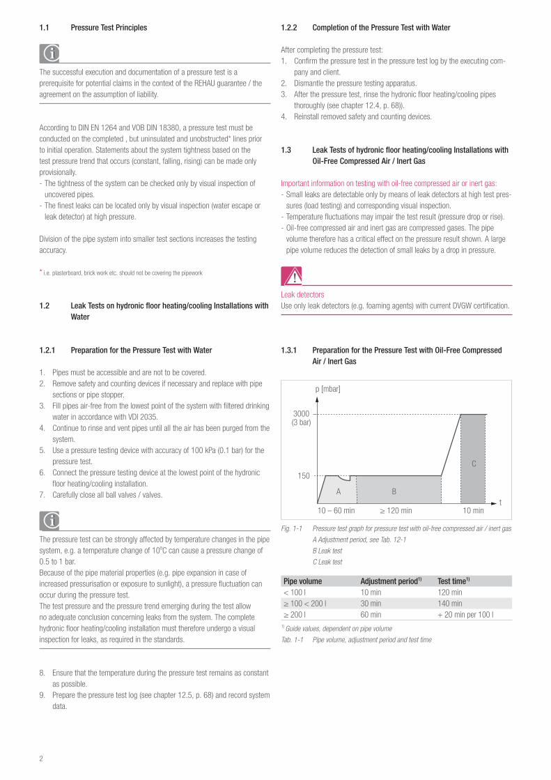
Fig. 1-1 Pressure test graph for pressure test with oil-free compressed air / inert gas
A Adjustment period, see Tab. 12-1
B Leak test
C Leak test
Pipe volume Adjustment period1) Test time1)
< 100 l 10 min 120 min≥ 100 < 200 l 30 min 140 min≥ 200 l 60 min + 20 min per 100 l
1) Guide values, dependent on pipe volume
Tab. 1-1 Pipe volume, adjustment period and test time
(3 bar)3000
150
10 – 60 min ≥ 120 min 10 min
p [mbar]
t
C
BA
3
Proj
ect D
esig
n / T
est L
ogs
1. Pipes must be accessible and are not to be covered.2. Remove safety and counting devices if necessary and replace with pipe
sections or pipe stopper.3. Install a sufficient number of venting valves at appropriate points for the
safe release of the compressed air.4. Install a manometer with a measuring accuracy of 1 kPa (1 mbar).5. Carefully close all ball valves / valves.
The test pressure and the result of the pressure test does not provide a con-clusive conclusion concerning leaks of the system. The complete sub-surface heating/cooling installation must therefore be checked for leaks by leak detec-tor and visual inspection, as required in the standards.
6. Ensure that the temperature during the pressure test remains as constant as possible.
7. Prepare the pressure test log (see chapter 12.5) and record the system data.
1 3 2 Leak Test
1. Select adjustment period and test duration according to Tab. 9-12. Slowly build up a test pressure of 150 mbar in the hydronic floor heating/
cooling installation.3. If necessary, build up the test pressure again after the adjustment period.4. Start the leak test after the adjustment period:5. Read the test pressure and record it in the pressure test log together with
the test duration.6. After the test time, record the test pressure in the pressure test log.7. Check the entire hydronic floor heating/cooling installation and particularly
the connecting points for leaks, by visual inspection with leak detector.
If the test pressure has dropped: - Carry out a fresh, precise visual inspection of the pipes, withdrawal and connecting point with leak detector.
- Eliminate the cause of the pressure drop and repeat the leak test (steps 1 – 5).
8. If no leak is found, record the visual inspection in the pressure test log.
1 3 3 Load Test
1. Slowly build up a test pressure of 3 bar in the hydronic floor heating/cool-ing installation.
2. After stabilising the pressure, re-establish the test pressure of 3 bar if necessary.
3. Read the test pressure and record it in the pressure test log.4. Read and record the test pressure after 10 minutes.5. Check the entire hydronic floor heating/cooling installation and particularly
the connecting points for leaks by visual inspection with leak detector.
If a leak is detected during the visual inspection: - Eliminate the leak and repeat the entire leak and load test.
6. If no leak is found, record the visual inspection in the pressure test log.7. Safely release the compressed air after completing the load test.
1 3 4 Completion of the Pressure Test with Oil-Free Compressed Air / Inert Gas
After completing the pressure test:1. Confirm the pressure test in the pressure test log by the executing com-
pany and client.2. Dismantle the pressure testing apparatus.3. Reinstall removed safety and counting devices.
1 4 Rinsing the Sub-surface Heating/Cooling Installation
To remove contamination from the storage and construction phase, all pipes must be rinsed for several minutes in accordance with the requirements of DIN EN 14336 and VDI 2035 sheet 2 “Prevention of Damage in Water Heat-ing/Cooling Installations” in a defined order and quantity.
The drainage of an hydronic floor heating/cooling installation after a pressure test with water should be avoided as per VDI 2035 sheet 2.
Use of water/antifreeze that is only temporary and subsequent filling with ad-ditional water without antifreeze is not recommended, as per VDI 2035 sheet 2.Appropriate measures should therefore be taken to prevent a risk of freezing both during and after the pressure test.
1 5 Pressure Inspection Sheet: REHAU Hydronic Floor Heating/Cooling
The template for a pressure test log can be downloaded from the internet at the address www.rehau.com.au/hydronic
4
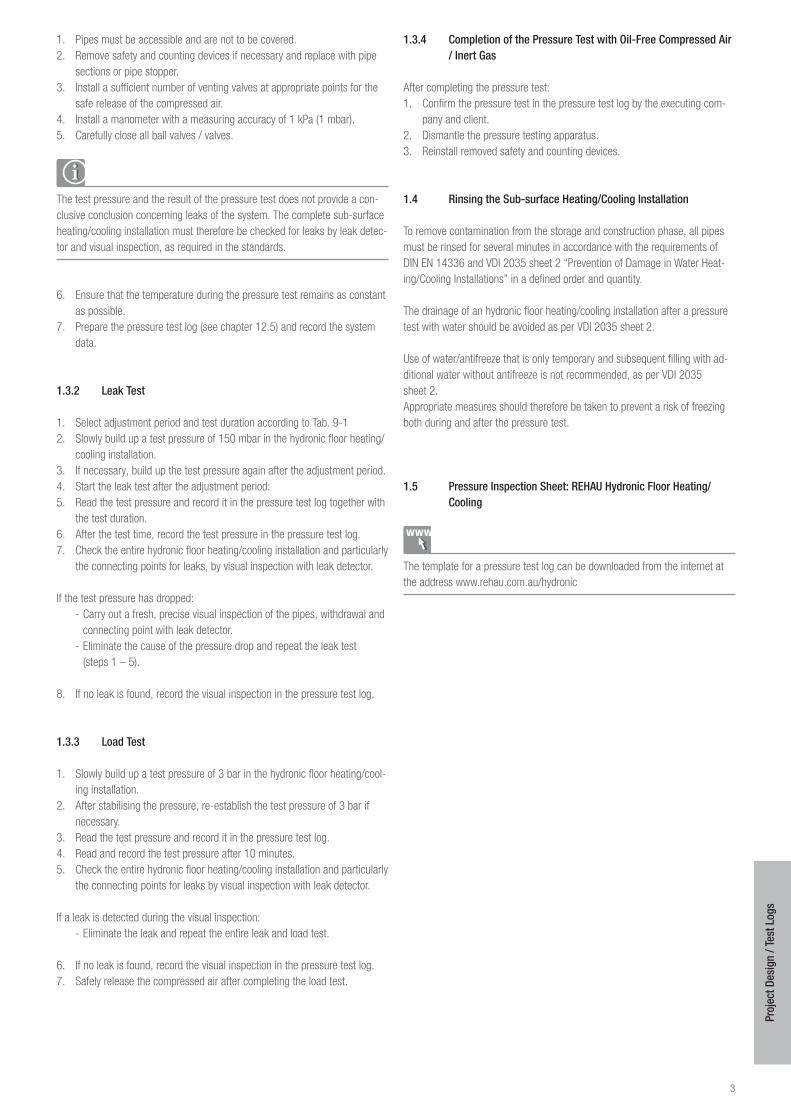
Pressure Test Log for REHAU Hydronic Floor Heating/Cooling with the Test Medium Water
Construction project:
Heating/cooling engineering company:
Screed laying company:
REHAU installation system:
REHAU pipe (type/nominal size/distance between pipes):
Screed type: cement screed cm thick Anhydrite screed cm thick
Date of screed installation:
External temperature before commencement of functional heating/cooling:
Room temperature before commencement of functional heating/cooling:
1. Set starting supply temperature of 20 – 25 °C and keep constant for 3 days:
Started on: Completed on:
2. Set max. permitted design temperature and maintain for min. 4 days (without night reduction):
Started on: Completed on:
In case of faults: Heating/cooling up discontinued on:
Defects found:
Functional heating/cooling executed defect-free: Yes No
Client Place, date Signature
Client Place, date Signature
The leak test has been properly executed. No leak occurred here and no permanent change of shape occurred on any component.
Note: After completion of functional heating/cooling, it is not guaranteed that the screed has reached the humidity level required to be ready for covering. The floorer must therefore check that the screed is ready for covering.
5
Proj
ect D
esig
n / T
est L
ogs
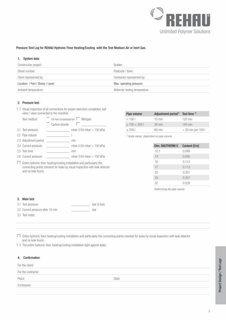
Pressure Test Log for REHAU Hydronic Floor Heating/Cooling with the Test Medium Air or Inert Gas
1 System data
Construction project: Builder:
Street number: Postcode / town:
Client represented by: Contractor represented by:
Location / Part / Storey / Level: Max. operating pressure:
Ambient temperature: Water/air testing temperature:
2 Pressure test
Visual inspection of all connections for proper execution completed, ball valve / valve connected to the manifold. Pipe volume Adjustment period1) Test time 1)
Test medium Oil-free compressed air Nitrogen < 100 l 10 min 120 min
Carbon dioxide _______________ ≥ 100 < 200 l 30 min 140 min
2.1 Test pressure ______________ mbar (150 mbar = 150 kPa) ≥ 200 l 60 min + 20 min per 100 l
2.2. Pipe volume ______________ l 1) Guide values, dependent on pipe volume2.3 Adjustment period ______________ min
2.4 Current pressure ______________ mbar (150 mbar = 150 kPa) Dim RAUTHERM S Content [l/m]
2.5 Test time ______________ min 10.1 0.049
2.6 Current pressure ______________ mbar (150 mbar = 150 kPa) 14 0.095
Entire hydronic floor heating/cooling installation and particularly the connecting points checked for leaks by visual inspection with leak detector and no leak found.
16 0.113
17 0.113
20 0.201
25 0.327
32 0.539
Determining the pipe volume
3 Main test
3.1 Test pressure ___________ bar (3 bar)
3.2 Current pressure after 10 min ___________ bar
3.3 Test notes:
Entire hydronic floor heating/cooling installation and particularly the connecting points checked for leaks by visual inspection with leak detector and no leak found.
The entire hydronic floor heating/cooling installation tight against leaks.
4 Confirmation
For the client:
For the contractor:
Place: Date:
Enclosures:
6
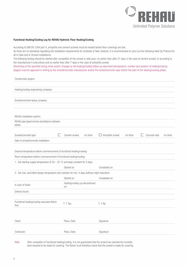
Functional Heating/Cooling Log for REHAU Hydronic Floor Heating/Cooling
According to DIN EN 1264 part 4, anhydrite and cement screeds must be heated before floor coverings are laid. As there are no standards regulating the installation requirements for Australia or New Zealand, it is recommended to carry out the following Heat Up Protocol for all In-Slab and In-Screed installations.The following testing should be started after completion of the screed or slab pour; no earlier than after 21 days in the case of cement screed; or according to the manufacturer’s instructions and no earlier than after 7 days in the case of anhydrite screed. Shortening of the specified drying times and/or changes to the heating/cooling follow-up described (temperature, number and duration of heating/cooling stages) must be approved in writing by the screed/concrete manufacturer and/or the screed/concrete layer before the start of the heating/cooling phase.
Construction project:
Heating/cooling engineering company:
Screed/concrete laying company:
REHAU installation system:
REHAU pipe (type/nominal size/distance between pipes):
Screed/concrete type: Cement screed cm thick Anhydrite screed cm thick Concrete slab cm thick
Date of screed/concrete installation:
External temperature before commencement of functional heating/cooling:
Room temperature before commencement of functional heating/cooling:
1. Set starting supply temperature of 20 – 25 °C and keep constant for 3 days:
Started on: Completed on:
2. Set max. permitted design temperature and maintain for min. 4 days (without night reduction):
Started on: Completed on:
In case of faults:Heating/cooling up discontinued on:
Defects found:
Functional heating/cooling executed defect-free:
Yes No
Client: Place, Date: Signature:
Contractor: Place, Date: Signature:
Note: After completion of functional heating/cooling, it is not guaranteed that the screed has reached the humidity level required to be ready for covering. The floorer must therefore check that the screed is ready for covering.
7
Proj
ect D
esig
n / T
est L
ogs
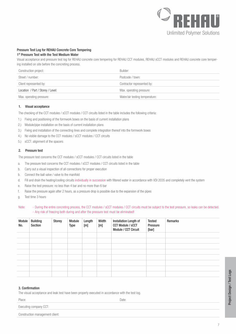
Pressure Test Log for REHAU Concrete Core Tempering 1st Pressure Test with the Test Medium WaterVisual acceptance and pressure test log for REHAU concrete core tempering for REHAU CCT modules, REHAU sCCT modules and REHAU concrete core temper-ing installed on site before the concreting process.
Construction project: Builder:
Street / number: Postcode / town:
Client represented by: Contractor represented by:
Location / Part / Storey / Level: Max. operating pressure:
Max. operating pressure: Water/air testing temperature:
1 Visual acceptance
The checking of the CCT modules / sCCT modules / CCT circuits listed in the table includes the following criteria:
1.) Fixing and positioning of the formwork boxes on the basis of current installation plans
2.) Module/pipe installation on the basis of current installation plans
3.) Fixing and installation of the connecting lines and complete integration thereof into the formwork boxes
4.) No visible damage to the CCT modules / sCCT modules / CCT circuits
5.) sCCT: alignment of the spacers
2 Pressure test
The pressure test concerns the CCT modules / sCCT modules / CCT circuits listed in the table
a. The pressure test concerns the CCT modules / sCCT modules / CCT circuits listed in the table
b. Carry out a visual inspection of all connections for proper execution
b. Connect the ball valve / valve to the manifold
d. Fill and drain the heating/cooling circuits individually in succession with filtered water in accordance with VDI 2035 and completely vent the system
e. Raise the test pressure: no less than 4 bar and no more than 6 bar
f. Raise the pressure again after 2 hours, as a pressure drop is possible due to the expansion of the pipes
g. Test time 3 hours
Note: - During the entire concreting process, the CCT modules / sCCT modules / CCT circuits must be subject to the test pressure, so leaks can be detected. - Any risk of freezing both during and after the pressure test must be eliminated!
Module No
Building Section
Storey Module Type
Length [m]
Width [m]
Installation Length of CCT Module / sCCT Module / CCT Circuit
Tested Pressure [bar]
Remarks
3 ConfirmationThe visual acceptance and leak test have been properly executed in accordance with the test log.
Place: Date:
Executing company CCT:
Construction management client:
8
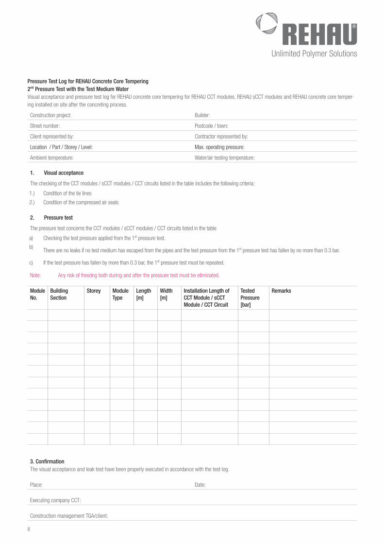
Pressure Test Log for REHAU Concrete Core Tempering 2nd Pressure Test with the Test Medium WaterVisual acceptance and pressure test log for REHAU concrete core tempering for REHAU CCT modules, REHAU sCCT modules and REHAU concrete core temper-ing installed on site after the concreting process.
Construction project: Builder:
Street number: Postcode / town:
Client represented by: Contractor represented by:
Location / Part / Storey / Level: Max. operating pressure:
Ambient temperature: Water/air testing temperature:
1 Visual acceptance
The checking of the CCT modules / sCCT modules / CCT circuits listed in the table includes the following criteria:
1.) Condition of the tie lines
2.) Condition of the compressed air seals
2 Pressure test
The pressure test concerns the CCT modules / sCCT modules / CCT circuits listed in the table
a) Checking the test pressure applied from the 1st pressure test.
b) There are no leaks if no test medium has escaped from the pipes and the test pressure from the 1st pressure test has fallen by no more than 0.3 bar.
c) If the test pressure has fallen by more than 0.3 bar, the 1st pressure test must be repeated.
Note: Any risk of freezing both during and after the pressure test must be eliminated.
Module No
Building Section
Storey Module Type
Length [m]
Width [m]
Installation Length of CCT Module / sCCT Module / CCT Circuit
Tested Pressure [bar]
Remarks
3 ConfirmationThe visual acceptance and leak test have been properly executed in accordance with the test log.
Place: Date:
Executing company CCT:
Construction management TGA/client:
9
Proj
ect D
esig
n / T
est L
ogs
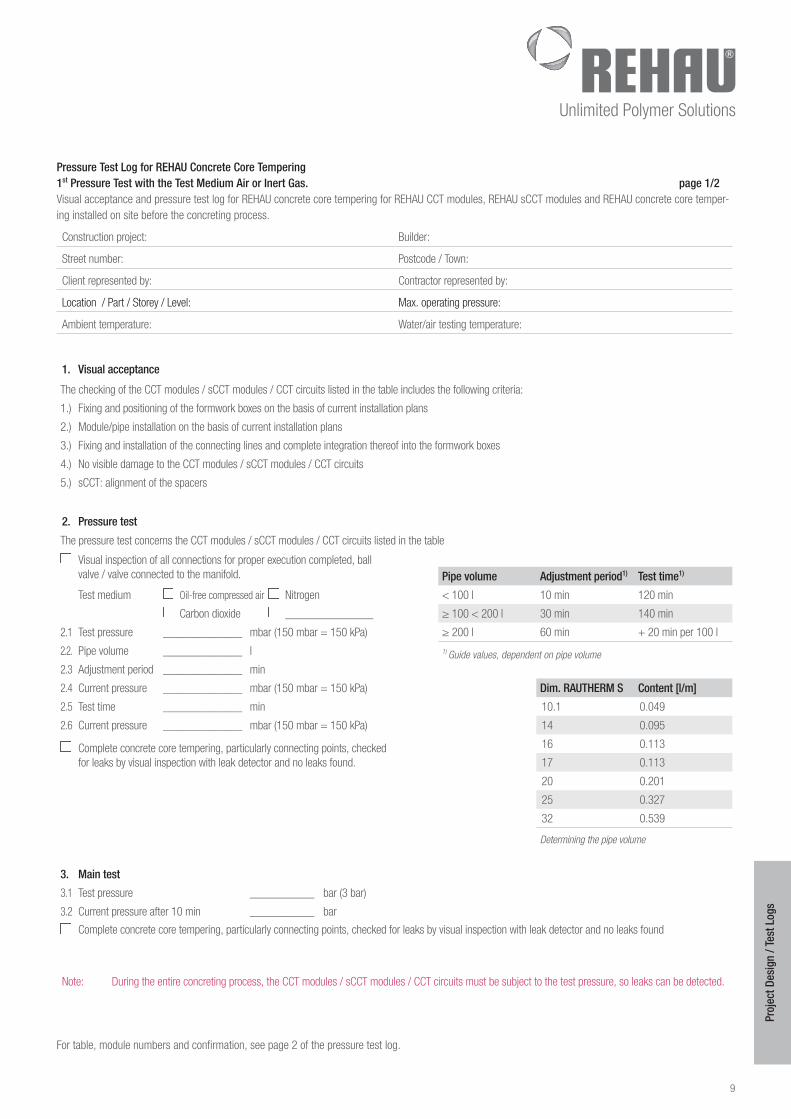
Pressure Test Log for REHAU Concrete Core Tempering 1st Pressure Test with the Test Medium Air or Inert Gas page 1/2Visual acceptance and pressure test log for REHAU concrete core tempering for REHAU CCT modules, REHAU sCCT modules and REHAU concrete core temper-ing installed on site before the concreting process.
Construction project: Builder:
Street number: Postcode / Town:
Client represented by: Contractor represented by:
Location / Part / Storey / Level: Max. operating pressure:
Ambient temperature: Water/air testing temperature:
1 Visual acceptance
The checking of the CCT modules / sCCT modules / CCT circuits listed in the table includes the following criteria:
1.) Fixing and positioning of the formwork boxes on the basis of current installation plans
2.) Module/pipe installation on the basis of current installation plans
3.) Fixing and installation of the connecting lines and complete integration thereof into the formwork boxes
4.) No visible damage to the CCT modules / sCCT modules / CCT circuits
5.) sCCT: alignment of the spacers
2 Pressure test
The pressure test concerns the CCT modules / sCCT modules / CCT circuits listed in the table
Visual inspection of all connections for proper execution completed, ball valve / valve connected to the manifold. Pipe volume Adjustment period1) Test time1)
Test medium Oil-free compressed air Nitrogen < 100 l 10 min 120 min
Carbon dioxide _______________ ≥ 100 < 200 l 30 min 140 min
2.1 Test pressure ______________ mbar (150 mbar = 150 kPa) ≥ 200 l 60 min + 20 min per 100 l
2.2. Pipe volume ______________ l 1) Guide values, dependent on pipe volume2.3 Adjustment period ______________ min
2.4 Current pressure ______________ mbar (150 mbar = 150 kPa) Dim RAUTHERM S Content [l/m]
2.5 Test time ______________ min 10.1 0.049
2.6 Current pressure ______________ mbar (150 mbar = 150 kPa) 14 0.095
Complete concrete core tempering, particularly connecting points, checked for leaks by visual inspection with leak detector and no leaks found.
16 0.113
17 0.113
20 0.201
25 0.327
32 0.539
Determining the pipe volume
3 Main test
3.1 Test pressure ___________ bar (3 bar)
3.2 Current pressure after 10 min ___________ bar
Complete concrete core tempering, particularly connecting points, checked for leaks by visual inspection with leak detector and no leaks found
Note: During the entire concreting process, the CCT modules / sCCT modules / CCT circuits must be subject to the test pressure, so leaks can be detected.
For table, module numbers and confirmation, see page 2 of the pressure test log.
10
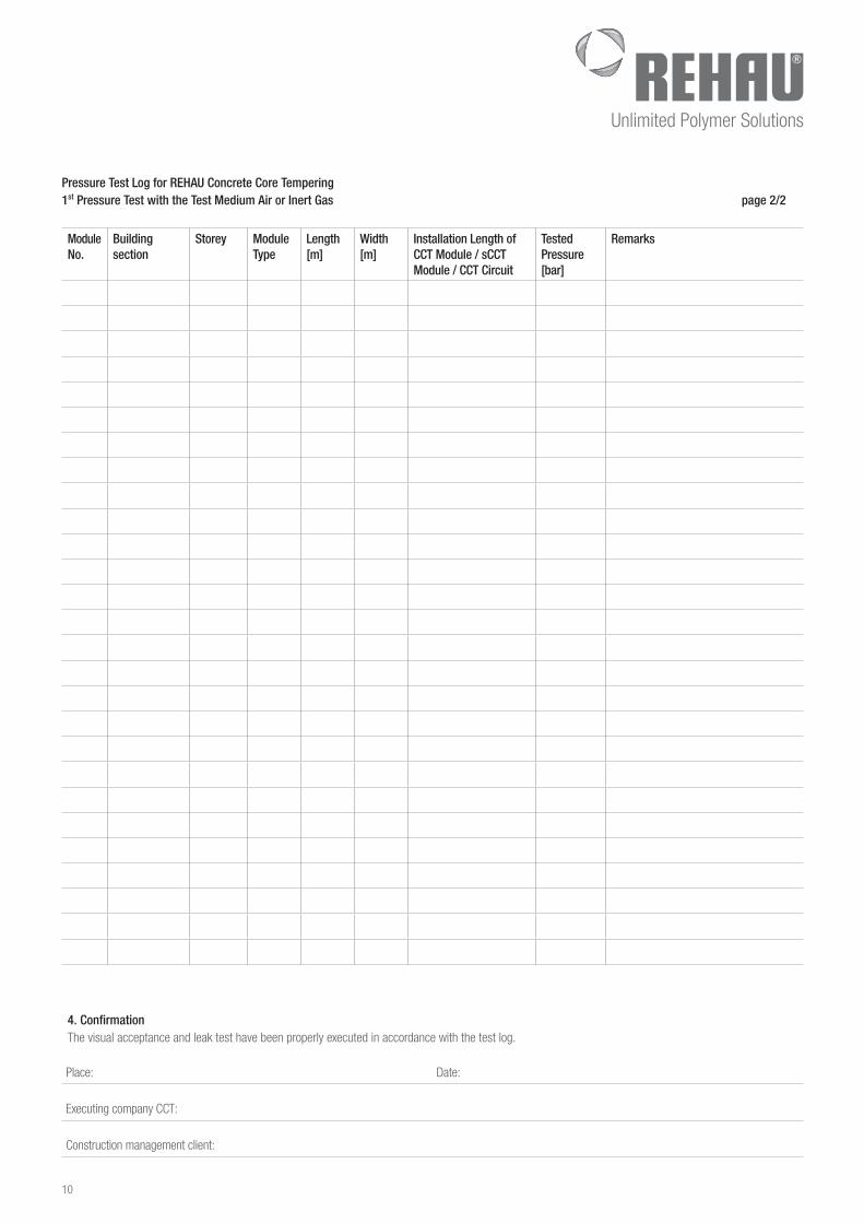
Pressure Test Log for REHAU Concrete Core Tempering 1st Pressure Test with the Test Medium Air or Inert Gas page 2/2
Module No
Building section
Storey Module Type
Length [m]
Width [m]
Installation Length of CCT Module / sCCT Module / CCT Circuit
Tested Pressure [bar]
Remarks
4 ConfirmationThe visual acceptance and leak test have been properly executed in accordance with the test log.
Place: Date:
Executing company CCT:
Construction management client:
11
Proj
ect D
esig
n / T
est L
ogs
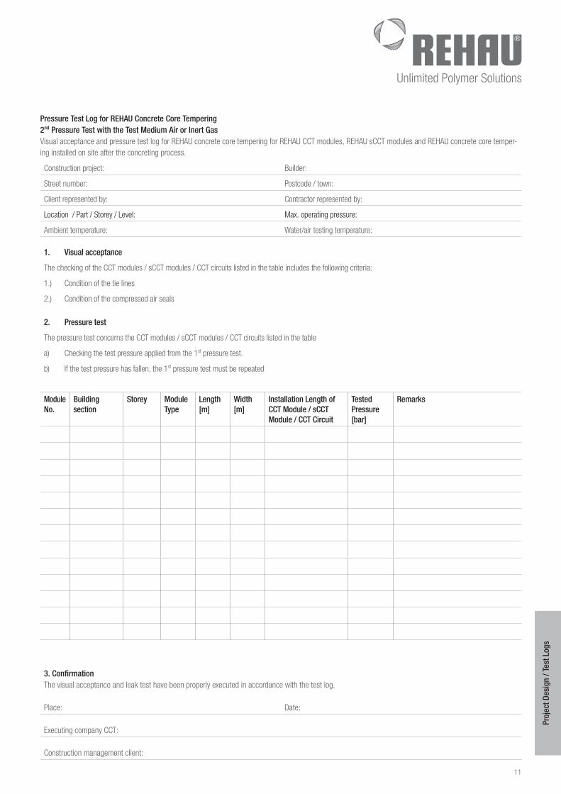
Pressure Test Log for REHAU Concrete Core Tempering 2nd Pressure Test with the Test Medium Air or Inert GasVisual acceptance and pressure test log for REHAU concrete core tempering for REHAU CCT modules, REHAU sCCT modules and REHAU concrete core temper-ing installed on site after the concreting process.
Construction project: Builder:
Street number: Postcode / town:
Client represented by: Contractor represented by:
Location / Part / Storey / Level: Max. operating pressure:
Ambient temperature: Water/air testing temperature:
1 Visual acceptance
The checking of the CCT modules / sCCT modules / CCT circuits listed in the table includes the following criteria:
1.) Condition of the tie lines
2.) Condition of the compressed air seals
2 Pressure test
The pressure test concerns the CCT modules / sCCT modules / CCT circuits listed in the table
a) Checking the test pressure applied from the 1st pressure test.
b) If the test pressure has fallen, the 1st pressure test must be repeated
Module No
Building section
Storey Module Type
Length [m]
Width [m]
Installation Length of CCT Module / sCCT Module / CCT Circuit
Tested Pressure [bar]
Remarks
3 ConfirmationThe visual acceptance and leak test have been properly executed in accordance with the test log.
Place: Date:
Executing company CCT:
Construction management client:
12
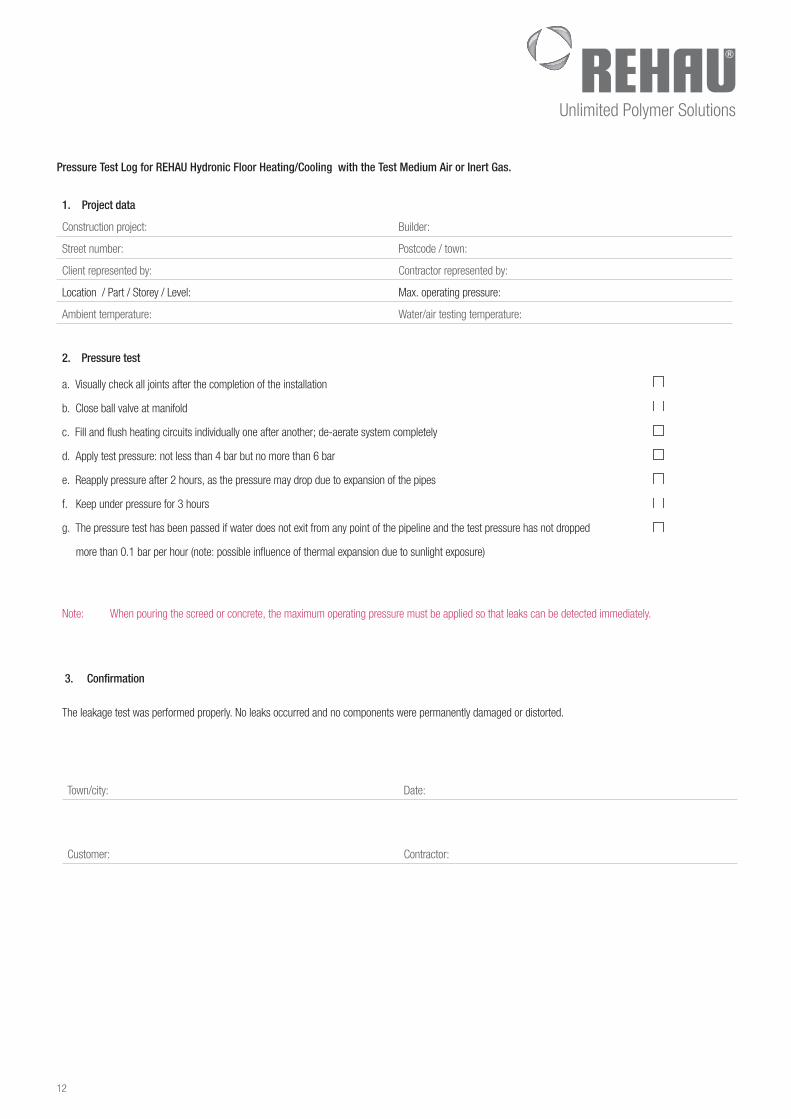
Pressure Test Log for REHAU Hydronic Floor Heating/Cooling with the Test Medium Air or Inert Gas
1 Project data
Construction project: Builder:
Street number: Postcode / town:
Client represented by: Contractor represented by:
Location / Part / Storey / Level: Max. operating pressure:
Ambient temperature: Water/air testing temperature:
2 Pressure test
a. Visually check all joints after the completion of the installation
b. Close ball valve at manifold
c. Fill and flush heating circuits individually one after another; de-aerate system completely
d. Apply test pressure: not less than 4 bar but no more than 6 bar
e. Reapply pressure after 2 hours, as the pressure may drop due to expansion of the pipes
f. Keep under pressure for 3 hours
g. The pressure test has been passed if water does not exit from any point of the pipeline and the test pressure has not dropped
more than 0.1 bar per hour (note: possible influence of thermal expansion due to sunlight exposure)
Note: When pouring the screed or concrete, the maximum operating pressure must be applied so that leaks can be detected immediately.
3 Confirmation
The leakage test was performed properly. No leaks occurred and no components were permanently damaged or distorted.
Town/city: Date:
Customer: Contractor: